light bar bumper kit precedent
TRANSCRIPT
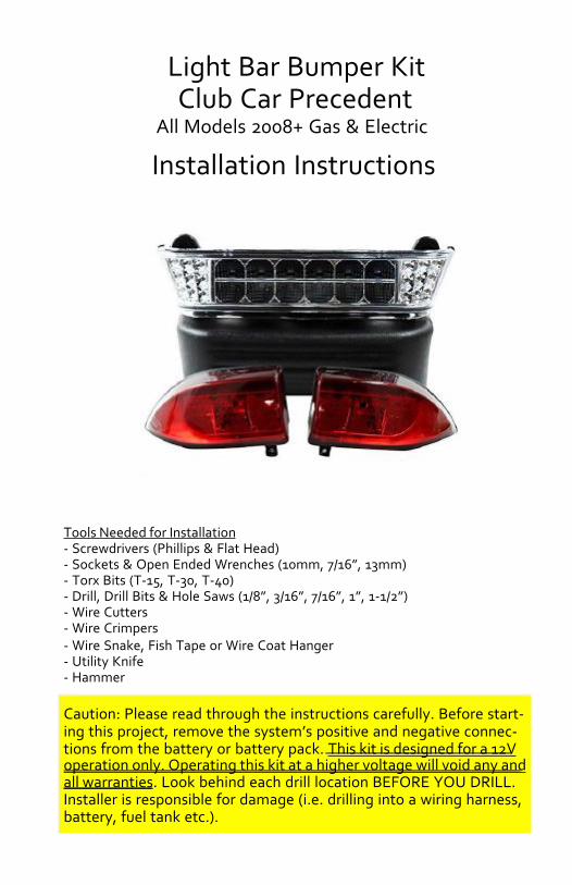
Tools Needed for Installation- Screwdrivers (Phillips & Flat Head)- Sockets & Open Ended Wrenches (10mm, 7/16”, 13mm)- Torx Bits (T-15, T-30, T-40)- Drill, Drill Bits & Hole Saws (1/8”, 3/16”, 7/16”, 1”, 1-1/2”)- Wire Cutters- Wire Crimpers- Wire Snake, Fish Tape or Wire Coat Hanger- Utility Knife- Hammer
Caution: Please read through the instructions carefully. Before start-ing this project, remove the system’s positive and negative connec-tions from the battery or battery pack. This kit is designed for a 12Voperation only. Operating this kit at a higher voltage will void any andall warranties. Look behind each drill location BEFORE YOU DRILL.Installer is responsible for damage (i.e. drilling into a wiring harness,battery, fuel tank etc.).
Light Bar Bumper KitClub Car Precedent
All Models 2008+ Gas & Electric
Installation Instructions
Page 3
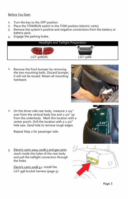
LGT-306E/EL LGT-306E
Before You Start
1.2.3.
4.
Turn the key to the OFF position.Place the TOW/RUN switch in the TOW position (electric carts).Remove the system’s positive and negative connections from the battery orbattery pack.Engage the parking brake.
Headlight and Taillight Preparation
1.
2.
3.
Remove the front bumper by removingthe two mounting bolts. Discard bumper,it will not be reused. Retain all mountinghardware.
On the driver side rear body, measure 2-1/4”over from the vertical body line and 1-1/2” upfrom the underbody. Mark this location with acenter punch. Drill the location with a 1-1/2”hole saw. Sand hole to remove rough edges.
Repeat Step 2 for passenger side.
Electric carts 2004-2008.5 and gas carts:reach inside the holes of the rear bodyand pull the taillight connectors throughthe holes.
Electric carts 2008.5+: install theLGT-396 bucket harness (page 5).
Page 4
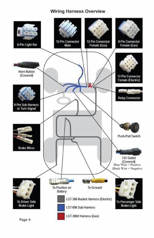
Blue Wire = PositiveBlack Wire = Negative
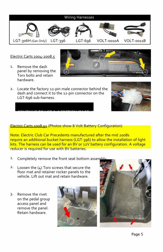
Wiring Harnesses
Electric Carts 2004-2008.5
1.
2.
Remove the dashpanel by removing theTorx bolts and retainhardware.
Locate the factory 12-pin male connector behind thedash and connect it to the 12-pin connector on theLGT-696 sub-harness.
CONTINUE TO LGT-696 SECTION (PAGE 9)
Electric Carts 2008.5+ (Photos show 8 Volt Battery Configuration)
Note: Electric Club Car Precedents manufactured after the mid 2008srequire an additional bucket harness (LGT-396) to allow the installation of lightkits. The harness can be used for an 8V or 12V battery configuration. A voltagereducer is required for use with 8V batteries.
1.
2.
3.
Completely remove the front seat bottom assembly.
Loosen the (4) Torx screws that secure thefloor mat and retainer rocker panels to thevehicle. Lift out mat and retain hardware.
Remove the riveton the pedal groupaccess panel andremove the panel.Retain hardware.
Page 5
LGT-696LGT-306H (Gas Only) LGT-396 VOLT-0011BVOLT-0010A
4.
5.
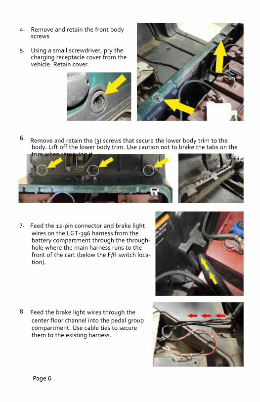
Remove and retain the front bodyscrews.
Using a small screwdriver, pry thecharging receptacle cover from thevehicle. Retain cover.
6.
7.
8.
Remove and retain the (3) screws that secure the lower body trim to thebody. Lift off the lower body trim. Use caution not to brake the tabs on thetrim when removing it.
Feed the 12-pin connector and brake lightwires on the LGT-396 harness from thebattery compartment through the through-hole where the main harness runs to thefront of the cart (below the F/R switch loca-tion).
Feed the brake light wires through thecenter floor channel into the pedal groupcompartment. Use cable ties to securethem to the existing harness.
Page 6
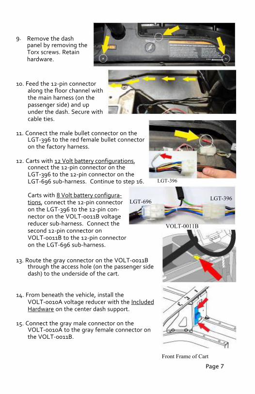
9. Remove the dashpanel by removing theTorx screws. Retainhardware.
10. Feed the 12-pin connectoralong the floor channel withthe main harness (on thepassenger side) and upunder the dash. Secure withcable ties.
11. Connect the male bullet connector on theLGT-396 to the red female bullet connectoron the factory harness.
12. Carts with 12 Volt battery configurations,connect the 12-pin connector on theLGT-396 to the 12-pin connector on theLGT-696 sub-harness. Continue to step 16.
LGT-696Carts with 8 Volt battery configura-tions, connect the 12-pin connectoron the LGT-396 to the 12-pin con-nector on the VOLT-0011B voltagereducer sub-harness. Connect thesecond 12-pin connector onVOLT-0011B to the 12-pin connectoron the LGT-696 sub-harness.
13. Route the gray connector on the VOLT-0011Bthrough the access hole (on the passenger sidedash) to the underside of the cart.
14. From beneath the vehicle, install theVOLT-0010A voltage reducer with the IncludedHardware on the center dash support.
15. Connect the gray male connector on theVOLT-0010A to the gray female connector onthe VOLT-0011B.
LGT-396
LGT-396
VOLT-0011B
Front Frame of Cart
Page 7
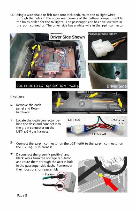
16. Using a wire snake or fish tape (not included), route the taillight wiresthrough the holes in the upper rear corners of the battery compartment tothe holes drilled for the taillights. The passenger side has a yellow wire inthe 3-pin connector. The driver side has a white wire in the 3-pin connector.
CONTINUE TO LGT-696 SECTION (PAGE 9)
Gas Carts
1. Remove the dashpanel and Retainhardware.
2. Locate the 9-pin connector be-hind the dash and connect it tothe 9-pin connector on theLGT-306H gas harness.
3.
4.
Connect the 12-pin connector on the LGT-306H to the 12-pin connector onthe LGT-696 sub-harness.
Disconnect the green (+ positive) andblack wires from the voltage regulatorand route them through the access holein the passenger side dash. Remembertheir locations for reassembly.
+ Positive
Page 8
LGT-696
LGT-306H
To 9-Pin onCart

LGT-306ELLGT-306E
5.
6.
From beneath the vehicle, install the voltageregulator with the Included Hardware on therear side of the center dash support.
Reconnect the green and black wires to theiroriginal locations on the voltage regulator.
CONTINUE TO LGT-696 SECTION BELOW
LGT-696 Sub-Harness
1.
2.
3.
Route the 6-pin connector, on the LGT-696 harness, for the light bar throughthe access hole in the passenger sidedash.
If powering the lights with the push-pullswitch included on the LGT-696 sub-harness, locate the indentation to theright of the key switch on the dash paneland drill a 7/16” hole.
NOTE: If Installing the LGT-132A turnsignal, do not install the push-pull switch.
Remove the knob, retaining nuts and washer from the push-pull switch andinsert the shaft of the switch into the newly drilled hole.
Secure using the retaining nuts and washer.Reattach knob.
Headlight Bumper
NOTE: If installing other accessories, do so before installing the headlightbumper bar.
Page 9

Page 10
1.
2.
3.
4.
1.
2.
3.
4.
Run the 6-pin connector on thesub-harness around the pas-senger side of the chassis andunder the shock.
Connect the 6-pin connectoron the LGT-696 to the 6-pinconnector on the light bar.
Install the headlight bumper using the OriginalBumper Mounting Hardware.
Reinstall dash panel using Original Hardware.
Taillights
LGT-306E/EL
Connect the taillights to the wire harness that waspulled through the hole in the rear body.
Test fit each taillight. They should rest on the un-derbody and line up with the edge of the bagwell.
NOTE: Do not expose double sided tape untillights are functioning and have been test fit.
Clean the mounting surface with rubbing alcohol.If the taillights function properly, remove thepaper on the double sided tape and mount thetaillights on the rear body.
Use the Included Screws to further secure thetaillights.
Power Connections
GroundPositive LeadFuse Harness
Page 11
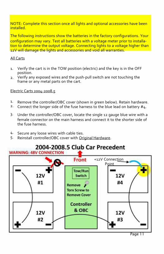
NOTE: Complete this section once all lights and optional accessories have beeninstalled.
The following instructions show the batteries in the factory configurations. Yourconfiguration may vary. Test all batteries with a voltage meter prior to installa-tion to determine the output voltage. Connecting lights to a voltage higher than12V will damage the lights and accessories and void all warranties.
All Carts
1.
2.
Verify the cart is in the TOW position (electric) and the key is in the OFFposition.Verify any exposed wires and the push-pull switch are not touching theframe or any metal parts on the cart.
Electric Carts 2004-2008.5
1.2.
3.
4.5.
Remove the controller/OBC cover (shown in green below). Retain hardware.Connect the longer side of the fuse harness to the blue lead on battery #4.
Under the controller/OBC cover, locate the single 12 gauge blue wire with afemale connector on the main harness and connect it to the shorter side ofthe fuse harness.
Secure any loose wires with cable ties.Reinstall controller/OBC cover with Original Hardware.
+12V ConnectionPoint
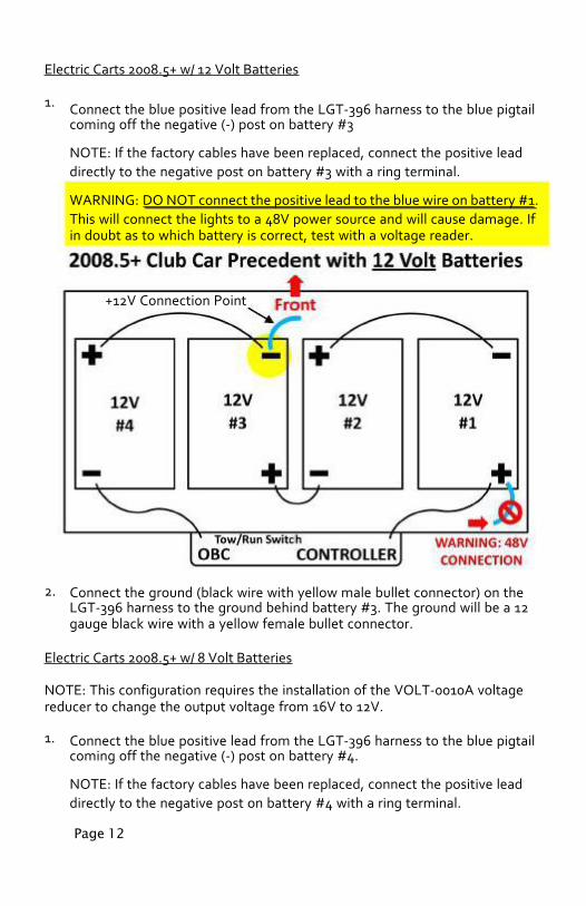
2. Connect the ground (black wire with yellow male bullet connector) on theLGT-396 harness to the ground behind battery #3. The ground will be a 12gauge black wire with a yellow female bullet connector.
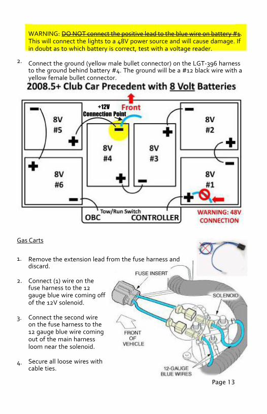
Electric Carts 2008.5+ w/ 8 Volt Batteries
NOTE: This configuration requires the installation of the VOLT-0010A voltagereducer to change the output voltage from 16V to 12V.
1. Connect the blue positive lead from the LGT-396 harness to the blue pigtailcoming off the negative (-) post on battery #4.
NOTE: If the factory cables have been replaced, connect the positive leaddirectly to the negative post on battery #4 with a ring terminal.
Page 12
Electric Carts 2008.5+ w/ 12 Volt Batteries
1. Connect the blue positive lead from the LGT-396 harness to the blue pigtailcoming off the negative (-) post on battery #3
NOTE: If the factory cables have been replaced, connect the positive leaddirectly to the negative post on battery #3 with a ring terminal.
WARNING: DO NOT connect the positive lead to the blue wire on battery #1.This will connect the lights to a 48V power source and will cause damage. Ifin doubt as to which battery is correct, test with a voltage reader.
+12V Connection Point
Page 13
Gas Carts
1.
2.
3.
4.
Remove the extension lead from the fuse harness anddiscard.
Connect (1) wire on thefuse harness to the 12gauge blue wire coming offof the 12V solenoid.
Connect the second wireon the fuse harness to the12 gauge blue wire comingout of the main harnessloom near the solenoid.
Secure all loose wires withcable ties.
2.
WARNING: DO NOT connect the positive lead to the blue wire on battery #1.This will connect the lights to a 48V power source and will cause damage. Ifin doubt as to which battery is correct, test with a voltage reader.
Connect the ground (yellow male bullet connector) on the LGT-396 harnessto the ground behind battery #4. The ground will be a #12 black wire with ayellow female bullet connector.
+12VConnection Point

Turn Signal Assemblies
NOTE: If installing a steering column cover, do so before installing the turnsignal.
1. Mount the turn signal assembly in a convenient location on the steeringcolumn using the included hose clamp for the LGT-112 and the LGT-143.Mount the LGT-132A using the included collar and choose one of theincluded rubber inserts that best fits the diameter of the steering column.
2.
3.
4.
5.
6.
Connect the 9-pin connector on the turn signal switchto the 9-pin connector on the LGT-696 sub-harness.
If installing the LGT-132A, removethe push-pull switch at the 4-pinconnector and replace it with theLGT-590 relay harness.
Connect the included flasher relay to the turn signal switchwire harness. LLED.Measure from the turn signal boot to thedash. Using a utility knife, saw or tinsnips, cut the LGT-107A, universal turnsignal switch wire cover, to length.
Snap the cover around the wires of the turnsignal switch and the steering column.
Page 14
LGT-112 LGT-132A LGT-143
LGT-112 LGT-143
LGT-107A
LGT-132A
Page 15
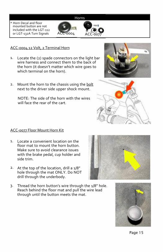
* Horn Decal and floormounted button are notincluded with the LGT-112or LGT-132A Turn Signals
ACC-0004 12 Volt, 2 Terminal Horn
1.
2.
Locate the (2) spade connectors on the light barwire harness and connect them to the back ofthe horn (it doesn’t matter which wire goes towhich terminal on the horn).
Mount the horn to the chassis using the boltnext to the driver side upper shock mount.
NOTE: The side of the horn with the wireswill face the rear of the cart.
ACC-0077 Floor Mount Horn Kit
1.
2.
3.
Locate a convenient location on thefloor mat to mount the horn button.Make sure to avoid clearance issueswith the brake pedal, cup holder andside trim.
At the top of the location, drill a 1/8”hole through the mat ONLY. Do NOTdrill through the underbody.
Thread the horn button’s wire through the 1/8” hole.Reach behind the floor mat and pull the wire leadthrough until the button meets the mat.
Horns
ACC-0004 ACC-0077

Page 16ACC-0088
4.
5.
6.
7.
8.
9.
Place the horn button decal over the button mak-ing sure it is even and the button is centered. Markthe (4) mounting holes. Remove the decal andbutton. Drill the (4) marked locations with a 3/16”drill bit through the mat ONLY.
Thread the horn button’s wire through the 1/8”hole, under the mat and up to the dash area. Placethe decal over the button. Mount the decal usingthe Included Rivets.
Locate the covered horn button connectors on theLGT-696 sub-harness and carefully remove thecover with a utility knife.
Connect the horn button wires to the butt connect-ors and crimp the connectors to secure (it doesn’tmatter which wire goes to which connector).
Route the horn button wires neatly behind thefloor mat and up into the dash area.
Locate the (2) spade connectors on the light barwire harness and connect them to the back ofthe horn (it doesn’t matter which wire goes towhich terminal on the horn).
10. Mount the horn to the chassis using the boltnext to the driver side upper shock mount.
NOTE: The side of the horn with the wireswill face the rear of the cart.
12 Volt Receptacle and/or Dual USB Outlet
ACC-0058
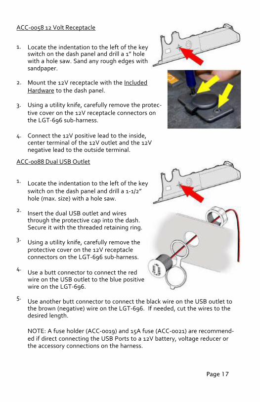
ACC-0058 12 Volt Receptacle
1.
2.
3.
4.
Locate the indentation to the left of the keyswitch on the dash panel and drill a 1” holewith a hole saw. Sand any rough edges withsandpaper.
Mount the 12V receptacle with the IncludedHardware to the dash panel.
Using a utility knife, carefully remove the protec-tive cover on the 12V receptacle connectors onthe LGT-696 sub-harness.
Connect the 12V positive lead to the inside,center terminal of the 12V outlet and the 12Vnegative lead to the outside terminal.
ACC-0088 Dual USB Outlet
1.
2.
3.
4.
5.
Locate the indentation to the left of the keyswitch on the dash panel and drill a 1-1/2”hole (max. size) with a hole saw.
Insert the dual USB outlet and wiresthrough the protective cap into the dash.Secure it with the threaded retaining ring.
Using a utility knife, carefully remove theprotective cover on the 12V receptacleconnectors on the LGT-696 sub-harness.
Use a butt connector to connect the redwire on the USB outlet to the blue positivewire on the LGT-696.
Use another butt connector to connect the black wire on the USB outlet tothe brown (negative) wire on the LGT-696. If needed, cut the wires to thedesired length.
NOTE: A fuse holder (ACC-0019) and 15A fuse (ACC-0021) are recommend-ed if direct connecting the USB Ports to a 12V battery, voltage reducer orthe accessory connections on the harness.
Page 17
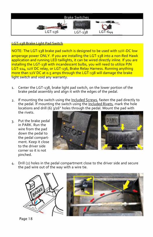
LGT-644LGT-136
Page 18
Brake Switches
LGT-138
LGT-138 Brake Light Pad Switch
NOTE: The LGT-138 brake pad switch is designed to be used with 12V–DC lowamperage power ONLY. If you are installing the LGT-138 into a non-Red Hawkapplication and running LED taillights, it can be wired directly inline. If you areinstalling the LGT-138 with incandescent bulbs, you will need to utilize P/NLGT-114, 12V DC relay, or LGT-136, Brake Relay Harness. Running anythingmore than 12V DC at 0.5 amps through the LGT-138 will damage the brakelight switch and void any warranty.
1.
2.
3.
4.
Center the LGT-138, brake light pad switch, on the lower portion of thebrake pedal assembly and align it with the edges of the pedal.
If mounting the switch using the Included Screws, fasten the pad directly tothe pedal. If mounting the switch using the Included Rivets, mark the holelocations and drill (6) 3/16” holes through the pedal. Mount the pad withthe rivets.
Put the brake pedalin PARK. Run thewire from the paddown the pedal tothe pedal compart-ment. Keep it closeto the driver sidecorner so it is notpinched.
Drill (2) holes in the pedal compartment close to the driver side and securethe pad wire out of the way with a wire tie.
Page 19
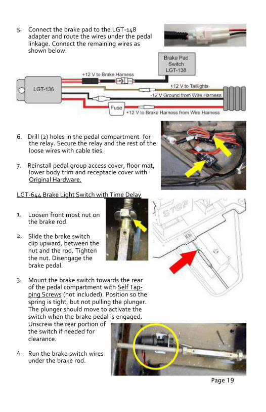
5. Connect the brake pad to the LGT-148adapter and route the wires under the pedallinkage. Connect the remaining wires asshown below.
6.
7.
Drill (2) holes in the pedal compartment forthe relay. Secure the relay and the rest of theloose wires with cable ties.
Reinstall pedal group access cover, floor mat,lower body trim and receptacle cover withOriginal Hardware.
LGT-644 Brake Light Switch with Time Delay
1.
2.
3.
4.
Loosen front most nut onthe brake rod.
Slide the brake switchclip upward, between thenut and the rod. Tightenthe nut. Disengage thebrake pedal.
Mount the brake switch towards the rearof the pedal compartment with Self Tap-ping Screws (not included). Position so thespring is tight, but not pulling the plunger.The plunger should move to activate theswitch when the brake pedal is engaged.Unscrew the rear portion ofthe switch if needed forclearance.
Run the brake switch wiresunder the brake rod.
5.
6.
7.
8.
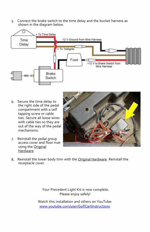
Connect the brake switch to the time delay and the bucket harness asshown in the diagram below.
Secure the time delay tothe right side of the pedalcompartment with a selftapping screw or cableties. Secure all loose wireswith cable ties so they areout of the way of the pedalmechanisms.
Reinstall the pedal groupaccess cover and floor matusing the OriginalHardware.
Reinstall the lower body trim with the Original Hardware. Reinstall thereceptacle cover.
Your Precedent Light Kit is now complete.Please enjoy safely!
Watch this installation and others on YouTube:www.youtube.com/user/GolfCartInstructions