light is technology.pdf
TRANSCRIPT
LIGHT IS TECHNOLOGY
KNOW-HOW FOR WORKSHOP PROFESSIONALS
EVERYTHING ABOUT LIGHTING TECHNOLOGY–ON 84 PAGESHELLA has represented competence and experience, for over 100 years. You can profit from this enormous experience. We offer you up-to-date and exhaustive information about lighting technology. This concentrated information contains everything a professional workshop needs. Our know-how for your success.
LIGHT SOURCES � Basic terms in lighting technology 5 � Factors that influence a light source 7 � Tips for dealing with light sources 11 � Technical data for the most common lights 12
HEADLIGHTS � Headlight components 17 � Tips for dealing with plastic cover lenses 20 � Technical lighting concepts 20 � Headlight Systems 21 � Xenon technology 25 � Daytime running light 30 � Headlight range adjustment 32 � Bend lighting 39 � LED technology 41 � Headlight cleaning system 56 � Checking and adjusting headlights 60
SIGNAL LIGHTS � Structure of a car signal light 63 � Tips for dealing with signal lights 64 � ASIGNIS® – Adaptive Signal System 65
INTELLIGENT LIGHTING SYSTEMS � Driver assistance system 67
LEGAL REGULATIONS AND TYPE APPROVAL NUMBERS � Headlights (Car and CV) 73 � Headlight range adjustment 77 � Headlight cleaning system 78 � Signal lights 78
CONTENTS
| 32
� Basic terms in lighting technology 5
� Factors that influence a light source 7
� Tips for dealing with light sources 11
� Technical data for the most common lights 12
LIGHT SOURCES
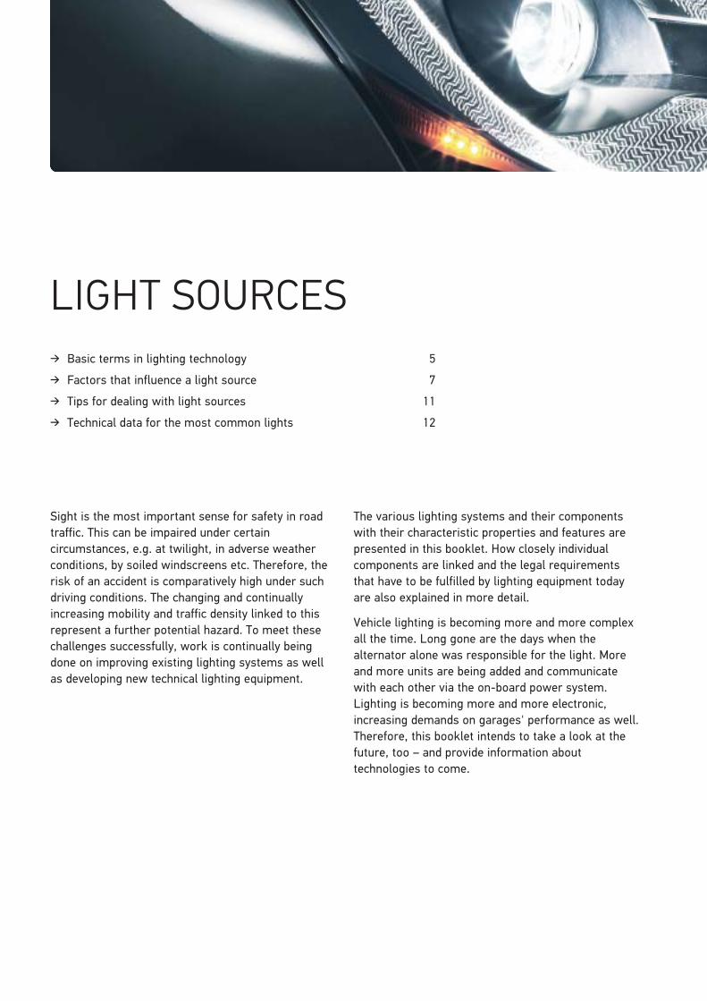
Sight is the most important sense for safety in road traffic. This can be impaired under certain circumstances, e.g. at twilight, in adverse weather conditions, by soiled windscreens etc. Therefore, the risk of an accident is comparatively high under such driving conditions. The changing and continually increasing mobility and traffic density linked to this represent a further potential hazard. To meet these challenges successfully, work is continually being done on improving existing lighting systems as well as developing new technical lighting equipment.
The various lighting systems and their components with their characteristic properties and features are presented in this booklet. How closely individual components are linked and the legal requirements that have to be fulfilled by lighting equipment today are also explained in more detail.
Vehicle lighting is becoming more and more complex all the time. Long gone are the days when the alternator alone was responsible for the light. More and more units are being added and communicate with each other via the on-board power system. Lighting is becoming more and more electronic, increasing demands on garages' performance as well. Therefore, this booklet intends to take a look at the future, too – and provide information about technologies to come.
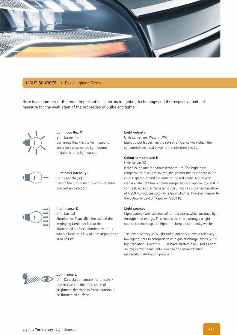
Luminous flux Φ
Unit: Lumen [lm]Luminous flux F is the term used to describe the complete light output radiated from a light source.
Luminous intensity I
Unit: Candela [cd]Part of the luminous flux which radiates in a certain direction.
Luminance L
Unit: Candela per square metre [cd/m2]Luminance L is the impression of brightness the eye has from a luminous or illuminated surface.
Illuminance E
Unit: Lux [lx]Illuminance E specifies the ratio of the impinging luminous flux to the illuminated surface. Illuminance is 1 lx when a luminous flux of 1 lm impinges an area of 1 m2.
Light output ŋ
Unit: Lumen per Watt [lm/W]Light output h specifies the rate of efficiency with which the consumed electrical power is transformed into light.
Colour temperature K
Unit: Kelvin [K]Kelvin is the unit for colour temperature. The higher the temperature of a light source, the greater the blue share in the colour spectrum and the smaller the red share. A bulb with warm white light has a colour temperature of approx. 2,700 K. In contrast, a gas discharge lamp (D2S) with a colour temperature of 4,250 K produces cold white light which is, however, nearer to the colour of daylight (approx. 5,600 K).
Light sources
Light sources are radiators of temperatures which produce light through heat energy. This means the more strongly a light source is heated up, the higher its luminous intensity will be.
The low efficiency (8 % light radiation) only allows a relatively low light output in comparison with gas discharge lamps (28 % light radiation). Recently, LEDs have started to be used as light source in front headlights. You can find more detailed information starting on page 41.
LIGHT SOURCES → Basic Lighting Terms
Here is a summary of the most important basic terms in lighting technology and the respective units of measure for the evaluation of the properties of bulbs and lights:
| 5Light is Technology Light Sources 4
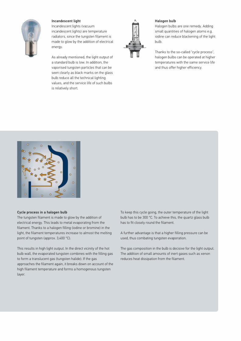
Halogen bulb
Halogen bulbs are one remedy. Adding small quantities of halogen atoms e.g. iodine can reduce blackening of the light bulb.
Thanks to the so-called "cycle process", halogen bulbs can be operated at higher temperatures with the same service life and thus offer higher efficiency.
Incandescent light
Incandescent lights (vacuum incandescent lights) are temperature radiators, since the tungsten filament is made to glow by the addition of electrical energy.
As already mentioned, the light output of a standard bulb is low. In addition, the vaporised tungsten particles that can be seen clearly as black marks on the glass bulb reduce all the technical lighting values, and the service life of such bulbs is relatively short.
Cycle process in a halogen bulb
The tungsten filament is made to glow by the addition of electrical energy. This leads to metal evaporating from the filament. Thanks to a halogen filling (iodine or bromine) in the light, the filament temperatures increase to almost the melting point of tungsten (approx. 3,400 °C).
This results in high light output. In the direct vicinity of the hot bulb wall, the evaporated tungsten combines with the filling gas to form a translucent gas (tungsten halide). If the gas approaches the filament again, it breaks down on account of the high filament temperature and forms a homogenous tungsten layer.
To keep this cycle going, the outer temperature of the light bulb has to be 300 °C. To achieve this, the quartz glass bulb has to fit closely round the filament.
A further advantage is that a higher filling pressure can be used, thus combating tungsten evaporation.
The gas composition in the bulb is decisive for the light output. The addition of small amounts of inert gases such as xenon reduces heat dissipation from the filament.
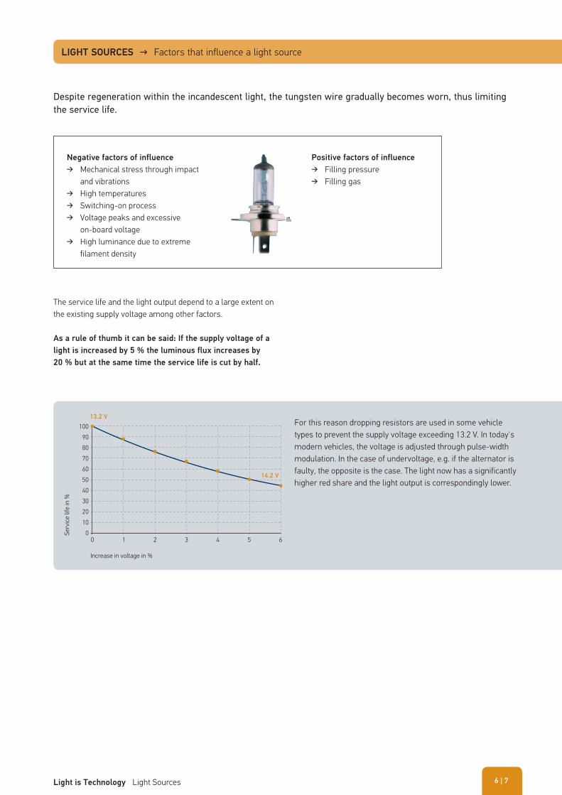
The service life and the light output depend to a large extent on the existing supply voltage among other factors.
As a rule of thumb it can be said: If the supply voltage of a
light is increased by 5 % the luminous flux increases by
20 % but at the same time the service life is cut by half.
Despite regeneration within the incandescent light, the tungsten wire gradually becomes worn, thus limiting the service life.
LIGHT SOURCES → Factors that influence a light source
For this reason dropping resistors are used in some vehicle types to prevent the supply voltage exceeding 13.2 V. In today's modern vehicles, the voltage is adjusted through pulse-width modulation. In the case of undervoltage, e.g. if the alternator is faulty, the opposite is the case. The light now has a significantly higher red share and the light output is correspondingly lower.
Serv
ice li
fe in
%
Increase in voltage in %
0
13.2 V
14.2 V
0102030405060708090
100
1 2 3 4 5 6
Negative factors of influence
� Mechanical stress through impact and vibrations
� High temperatures � Switching-on process � Voltage peaks and excessive
on-board voltage � High luminance due to extreme
filament density
Positive factors of influence
� Filling pressure � Filling gas
| 7Light is Technology Light Sources 6
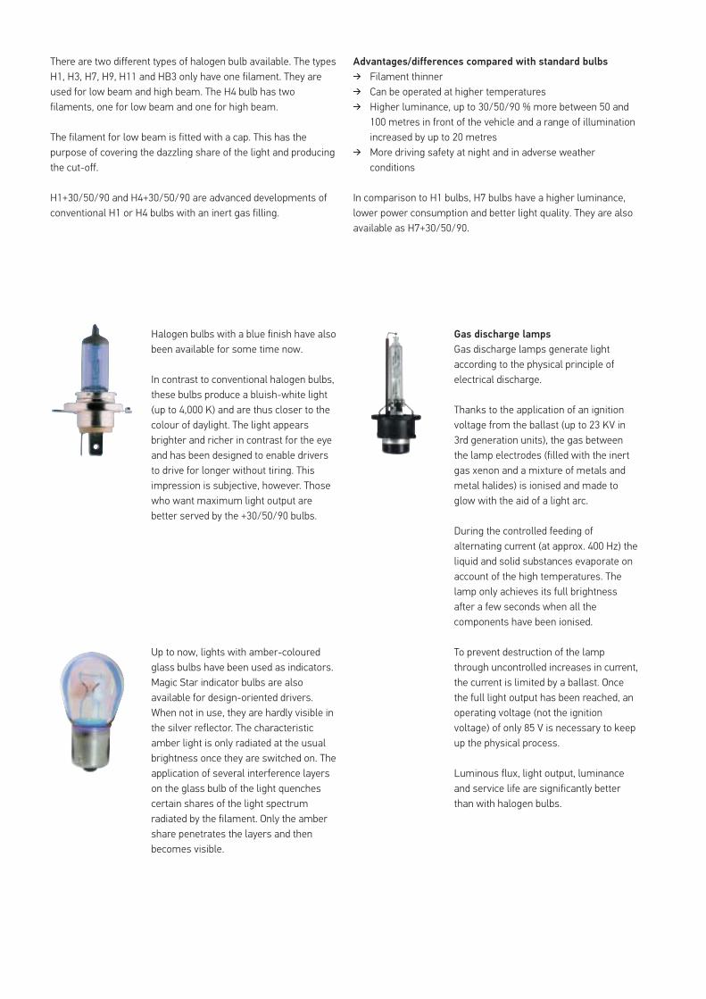
There are two different types of halogen bulb available. The types H1, H3, H7, H9, H11 and HB3 only have one filament. They are used for low beam and high beam. The H4 bulb has two filaments, one for low beam and one for high beam.
The filament for low beam is fitted with a cap. This has the purpose of covering the dazzling share of the light and producing the cut-off.
H1+30/50/90 and H4+30/50/90 are advanced developments of conventional H1 or H4 bulbs with an inert gas filling.
Advantages/differences compared with standard bulbs
� Filament thinner � Can be operated at higher temperatures � Higher luminance, up to 30/50/90 % more between 50 and
100 metres in front of the vehicle and a range of illumination increased by up to 20 metres
� More driving safety at night and in adverse weather conditions
In comparison to H1 bulbs, H7 bulbs have a higher luminance, lower power consumption and better light quality. They are also available as H7+30/50/90.
Up to now, lights with amber-coloured glass bulbs have been used as indicators. Magic Star indicator bulbs are also available for design-oriented drivers. When not in use, they are hardly visible in the silver reflector. The characteristic amber light is only radiated at the usual brightness once they are switched on. The application of several interference layers on the glass bulb of the light quenches certain shares of the light spectrum radiated by the filament. Only the amber share penetrates the layers and then becomes visible.
Halogen bulbs with a blue finish have also been available for some time now.
In contrast to conventional halogen bulbs, these bulbs produce a bluish-white light (up to 4,000 K) and are thus closer to the colour of daylight. The light appears brighter and richer in contrast for the eye and has been designed to enable drivers to drive for longer without tiring. This impression is subjective, however. Those who want maximum light output are better served by the +30/50/90 bulbs.
Gas discharge lamps
Gas discharge lamps generate light according to the physical principle of electrical discharge.
Thanks to the application of an ignition voltage from the ballast (up to 23 KV in 3rd generation units), the gas between the lamp electrodes (filled with the inert gas xenon and a mixture of metals and metal halides) is ionised and made to glow with the aid of a light arc.
During the controlled feeding of alternating current (at approx. 400 Hz) the liquid and solid substances evaporate on account of the high temperatures. The lamp only achieves its full brightness after a few seconds when all the components have been ionised.
To prevent destruction of the lamp through uncontrolled increases in current, the current is limited by a ballast. Once the full light output has been reached, an operating voltage (not the ignition voltage) of only 85 V is necessary to keep up the physical process.
Luminous flux, light output, luminance and service life are significantly better than with halogen bulbs.
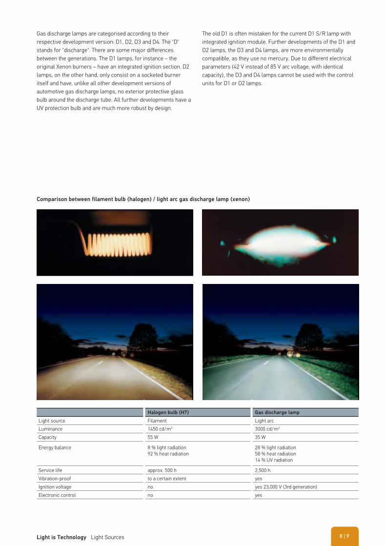
Comparison between filament bulb (halogen) / light arc gas discharge lamp (xenon)
Gas discharge lamps are categorised according to their respective development version: D1, D2, D3 and D4. The "D" stands for "discharge". There are some major differences between the generations. The D1 lamps, for instance – the original Xenon burners – have an integrated ignition section. D2 lamps, on the other hand, only consist on a socketed burner itself and have, unlike all other development versions of automotive gas discharge lamps, no exterior protective glass bulb around the discharge tube. All further developments have a UV protection bulb and are much more robust by design.
Halogen bulb (H7) Gas discharge lamp
Light source Filament Light arcLuminance 1450 cd/m2 3000 cd/m2
Capacity 55 W 35 W
Energy balance 8 % light radiation92 % heat radiation
28 % light radiation58 % heat radiation14 % UV radiation
Service life approx. 500 h 2,500 hVibration-proof to a certain extent yesIgnition voltage no yes 23,000 V (3rd generation)Electronic control no yes
The old D1 is often mistaken for the current D1 S/R lamp with integrated ignition module. Further developments of the D1 and D2 lamps, the D3 and D4 lamps, are more environmentally compatible, as they use no mercury. Due to different electrical parameters (42 V instead of 85 V arc voltage, with identical capacity), the D3 and D4 lamps cannot be used with the control units for D1 or D2 lamps.
| 9Light is Technology Light Sources 8
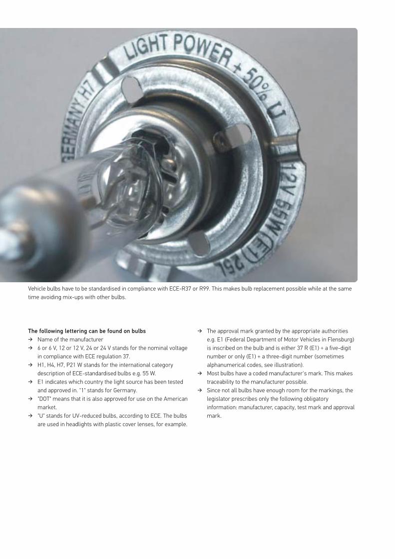
The following lettering can be found on bulbs
� Name of the manufacturer � 6 or 6 V, 12 or 12 V, 24 or 24 V stands for the nominal voltage
in compliance with ECE regulation 37. � H1, H4, H7, P21 W stands for the international category
description of ECE-standardised bulbs e.g. 55 W. � E1 indicates which country the light source has been tested
and approved in. "1" stands for Germany. � "DOT" means that it is also approved for use on the American
market. � "U" stands for UV-reduced bulbs, according to ECE. The bulbs
are used in headlights with plastic cover lenses, for example.
� The approval mark granted by the appropriate authorities e.g. E1 (Federal Department of Motor Vehicles in Flensburg) is inscribed on the bulb and is either 37 R (E1) + a five-digit number or only (E1) + a three-digit number (sometimes alphanumerical codes, see illustration).
� Most bulbs have a coded manufacturer's mark. This makes traceability to the manufacturer possible.
� Since not all bulbs have enough room for the markings, the legislator prescribes only the following obligatory information: manufacturer, capacity, test mark and approval mark.
Vehicle bulbs have to be standardised in compliance with ECE-R37 or R99. This makes bulb replacement possible while at the same time avoiding mix-ups with other bulbs.
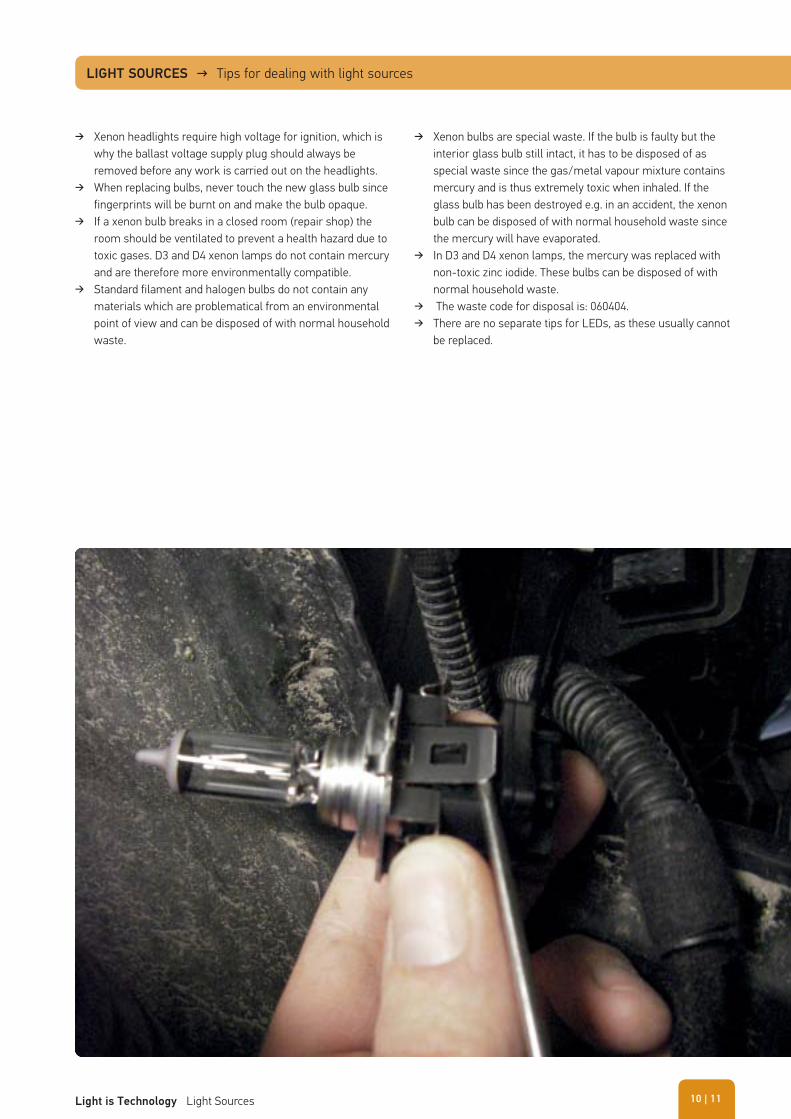
� Xenon headlights require high voltage for ignition, which is why the ballast voltage supply plug should always be removed before any work is carried out on the headlights.
� When replacing bulbs, never touch the new glass bulb since fingerprints will be burnt on and make the bulb opaque.
� If a xenon bulb breaks in a closed room (repair shop) the room should be ventilated to prevent a health hazard due to toxic gases. D3 and D4 xenon lamps do not contain mercury and are therefore more environmentally compatible.
� Standard filament and halogen bulbs do not contain any materials which are problematical from an environmental point of view and can be disposed of with normal household waste.
� Xenon bulbs are special waste. If the bulb is faulty but the interior glass bulb still intact, it has to be disposed of as special waste since the gas/metal vapour mixture contains mercury and is thus extremely toxic when inhaled. If the glass bulb has been destroyed e.g. in an accident, the xenon bulb can be disposed of with normal household waste since the mercury will have evaporated.
� In D3 and D4 xenon lamps, the mercury was replaced with non-toxic zinc iodide. These bulbs can be disposed of with normal household waste.
� The waste code for disposal is: 060404. � There are no separate tips for LEDs, as these usually cannot
be replaced.
LIGHT SOURCES → Tips for dealing with light sources
| 11Light is Technology Light Sources 10
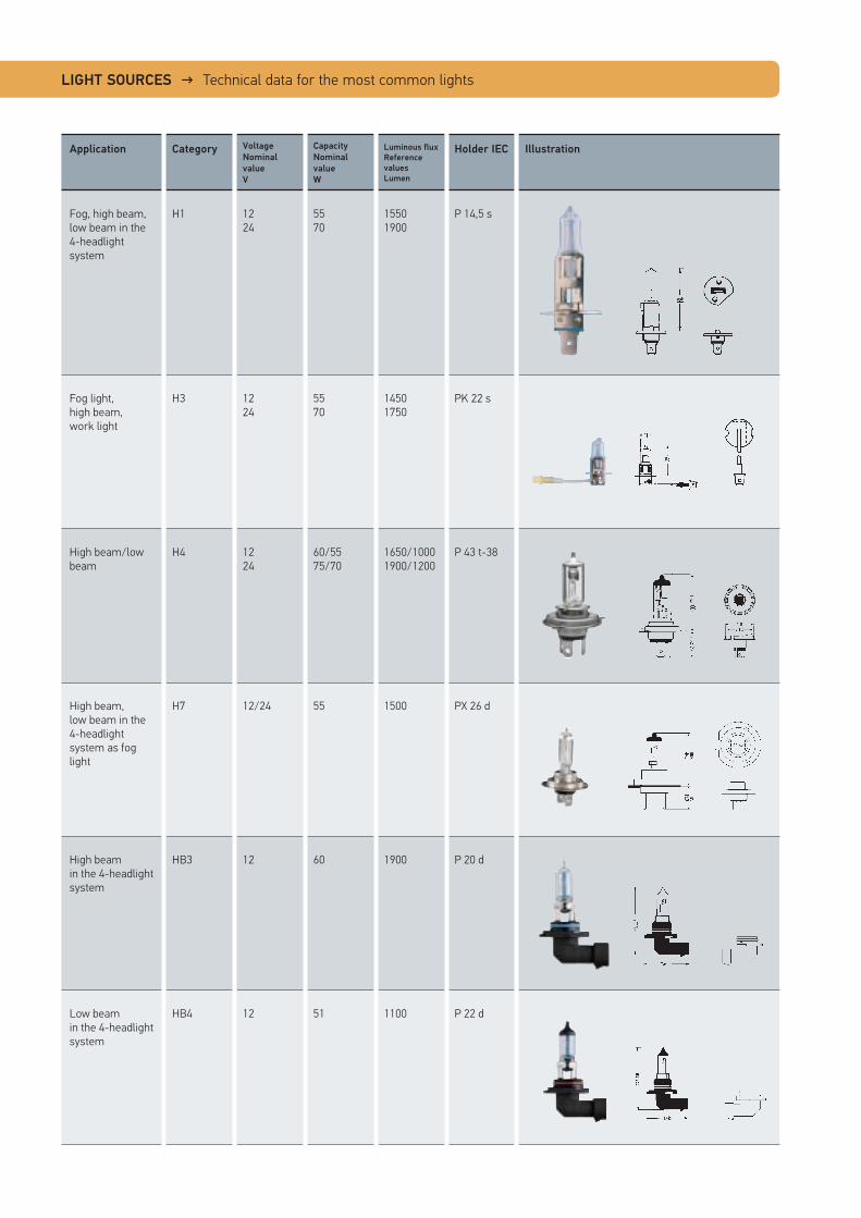
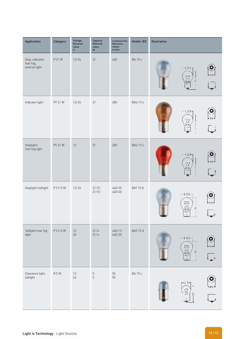
LIGHT SOURCES → Technical data for the most common lights
Application Category Voltage
Nominal
value
V
Capacity
Nominal
value
W
Luminous flux
Reference
values
Lumen
Holder IEC Illustration
Fog, high beam, low beam in the 4-headlight system
H1 1224
5570
15501900
P 14,5 s
Fog light, high beam, work light
H3 1224
5570
14501750
PK 22 s
High beam/low beam
H4 1224
60/5575/70
1650/10001900/1200
P 43 t-38
High beam, low beam in the 4-headlight system as fog light
H7 12/24 55 1500 PX 26 d
High beam in the 4-headlight system
HB3 12 60 1900 P 20 d
Low beam in the 4-headlight system
HB4 12 51 1100 P 22 d
Application Category Voltage
Nominal
value
V
Capacity
Nominal
value
W
Luminous flux
Reference
values
Lumen
Holder IEC Illustration
Stop, indicator,rear fog,reverse light
P 21 W 12/24 21 460 BA 15 s
Indicator light PY 21 W 12/24 21 280 BAU 15 s
Stoplight/rear fog light
PY 21 W 12 21 280 BAU 15 s
Stoplight/taillight P 21/5 W 12/24 21/5121/51
440/35440/40
BAY 15 d
Taillight/rear fog light
P 21/4 W 1224
21/421/4
440/15440/20
BAZ 15 d
Clearance light,taillight
R 5 W 1224
55
5050
BA 15 s
| 13Light is Technology Light Sources 12
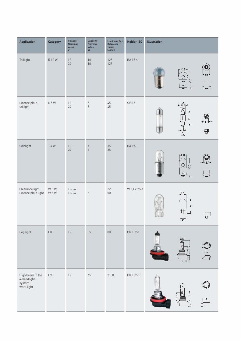
Application Category Voltage
Nominal
value
V
Capacity
Nominal
value
W
Luminous flux
Reference
values
Lumen
Holder IEC Illustration
Taillight R 10 W 1224
1010
125125
BA 15 s
Licence plate,taillight
C 5 W 1224
55
4545
SV 8,5
Sidelight T 4 W 1224
44
3535
BA 9 S
Clearance light,Licence plate light
W 3 WW 5 W
12/2412/24
35
2250
W 2,1 x 9,5 d
Fog light H8 12 35 800 PGJ 19-1
High beam in the 4-headlight system,work light
H9 12 65 2100 PGJ 19-5
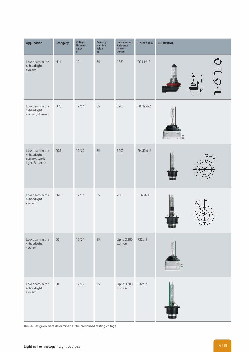
Application Category Voltage
Nominal
value
V
Capacity
Nominal
value
W
Luminous flux
Reference
values
Lumen
Holder IEC Illustration
Low beam in the 4-headlight system
H11 12 55 1350 PGJ 19-2
Low beam in the 4-headlight system, Bi-xenon
D1S 12/24 35 3200 PK 32 d-2
Low beam in the 4-headlight system, work light, Bi-xenon
D2S 12/24 35 3200 PK 32 d-2
Low beam in the 4-headlight system
D2R 12/24 35 2800 P 32 d-3
Low beam in the 4-headlight system
D3 12/24 35 Up to 3,200 Lumen
P32d-2
Low beam in the 4-headlight system
D4 12/24 35 Up to 3,200 Lumen
P32d-5
The values given were determined at the prescribed testing voltage.
| 15Light is Technology Light Sources 14
� Headlight components 17 � Tips for dealing with plastic cover lenses 20 � Technical lighting concepts 20 � Headlight Systems 21 � Xenon technology 25 � Daytime running light 30 � Headlight range adjustment 32 � Bend lighting 39 � LED technology 41 � Headlight cleaning system 56 � Checking and adjusting headlights 60
HEADLIGHTS
The primary task of vehicle headlights is to provide optimum illumination of the road in order to make fatigue-free and safe driving possible. Headlights including their light sources are thus safety-related vehicle parts which require approval from the
authorities and must not be manipulated in any way. Type and location of the lighting functions on the vehicle as well as their design, light sources, colours and photometric values are regulated by legislation.
HEADLIGHTS → Headlight components
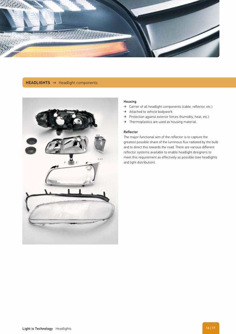
Housing
� Carrier of all headlight components (cable, reflector, etc.) � Attached to vehicle bodywork � Protection against exterior forces (humidity, heat, etc.) � Thermoplastics are used as housing material.
Reflector
The major functional aim of the reflector is to capture the greatest possible share of the luminous flux radiated by the bulb and to direct this towards the road. There are various different reflector systems available to enable headlight designers to meet this requirement as effectively as possible (see headlights and light distribution).
| 17Light is Technology Headlights 16
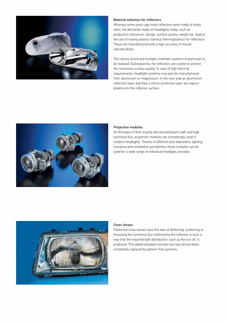
Material selection for reflectors
Whereas some years ago most reflectors were made of sheet steel, the demands made on headlights today, such as production tolerances, design, surface quality, weight etc. lead to the use of mainly plastics (various thermoplastics) for reflectors. These are manufactured with a high accuracy of mould reproducibility.
This allows tiered and multiple-chamber systems in particular to be realised. Subsequently, the reflectors are coated to achieve the necessary surface quality. In case of high thermal requirements, headlight systems may also be manufactured from aluminium or magnesium. In the next step an aluminium reflection layer and then a silicon protective layer are vapour-plated onto the reflector surface.
Projection modules
On the basis of their exactly demarcated beam path and high luminous flux, projection modules are increasingly used in modern headlights. Thanks to different lens diameters, lighting functions and installation possibilities these modules can be used for a wide range of individual headlight concepts.
Cover lenses
Patterned cover lenses have the task of deflecting, scattering or focussing the luminous flux collected by the reflector in such a way that the required light distribution, such as the cut-off, is produced. This dated standard concept has now almost been completely replaced by pattern-free systems.
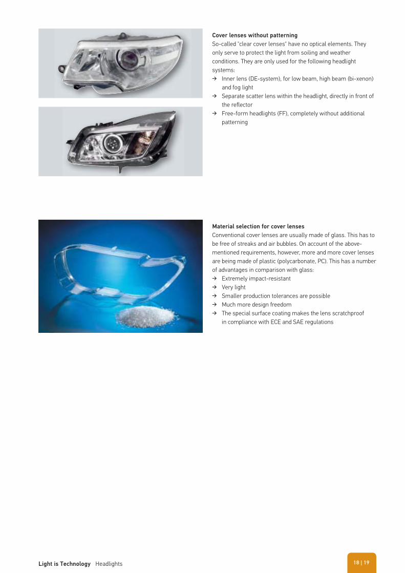
Material selection for cover lenses
Conventional cover lenses are usually made of glass. This has to be free of streaks and air bubbles. On account of the above-mentioned requirements, however, more and more cover lenses are being made of plastic (polycarbonate, PC). This has a number of advantages in comparison with glass:
� Extremely impact-resistant � Very light � Smaller production tolerances are possible � Much more design freedom � The special surface coating makes the lens scratchproof
in compliance with ECE and SAE regulations
Cover lenses without patterning
So-called "clear cover lenses" have no optical elements. They only serve to protect the light from soiling and weather conditions. They are only used for the following headlight systems:
� Inner lens (DE-system), for low beam, high beam (bi-xenon) and fog light
� Separate scatter lens within the headlight, directly in front of the reflector
� Free-form headlights (FF), completely without additional patterning
| 19Light is Technology Headlights 18
Tips for dealing with plastic cover lenses
� Never clean plastic cover lenses with a dry cloth (danger of scratches)!
� Before adding anything to the water in the lens cleaning system, such as a cleaning agent or anti-freeze, always check the instructions in the vehicle handbook.
� Cleaning chemicals which are too aggressive or of the wrong type can destroy plastic cover lenses.
� Never use impermissible high-wattage bulbs! � Only use bulbs with UV-filter!
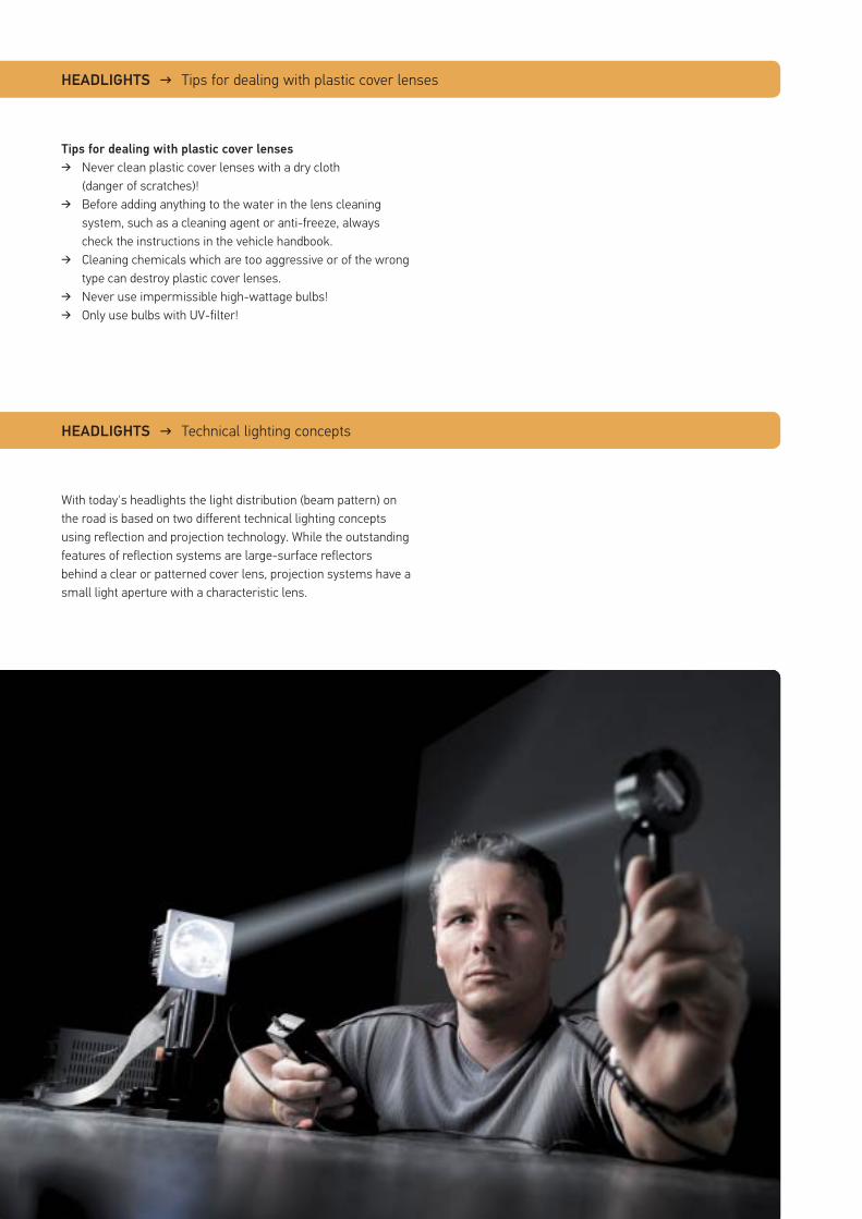
With today's headlights the light distribution (beam pattern) on the road is based on two different technical lighting concepts using reflection and projection technology. While the outstanding features of reflection systems are large-surface reflectors behind a clear or patterned cover lens, projection systems have a small light aperture with a characteristic lens.
HEADLIGHTS → Tips for dealing with plastic cover lenses
HEADLIGHTS → Technical lighting concepts
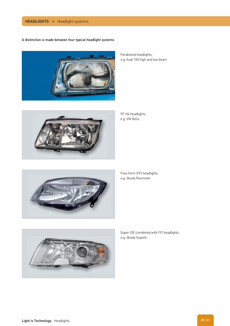
A distinction is made between four typical headlight systems
Paraboloid headlights,e.g. Audi 100 high and low beam
FF-H4 headlights, e.g. VW Bora
Free-form (FF) headlights,e.g. Skoda Roomster
Super-DE (combined with FF) headlights,e.g. Skoda Superb
HEADLIGHTS → Headlight systems
| 21Light is Technology Headlights 20
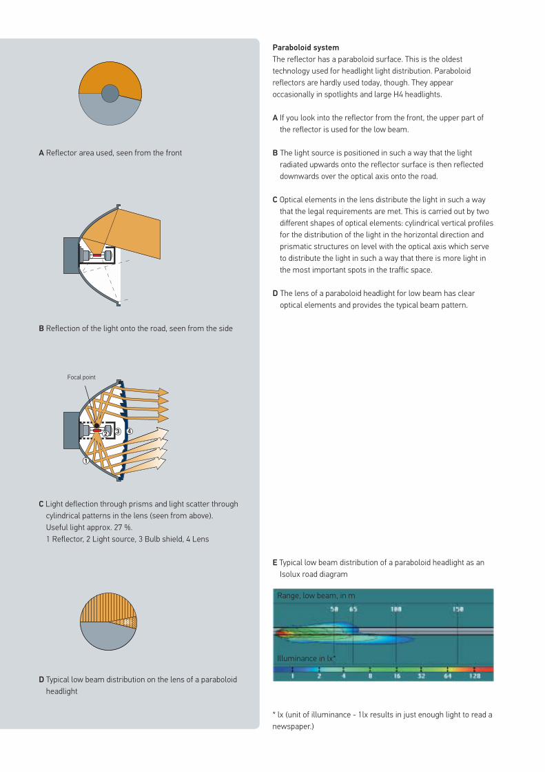
Paraboloid system
The reflector has a paraboloid surface. This is the oldest technology used for headlight light distribution. Paraboloid reflectors are hardly used today, though. They appear occasionally in spotlights and large H4 headlights.
A If you look into the reflector from the front, the upper part of the reflector is used for the low beam.
B The light source is positioned in such a way that the light radiated upwards onto the reflector surface is then reflected downwards over the optical axis onto the road.
C Optical elements in the lens distribute the light in such a way that the legal requirements are met. This is carried out by two different shapes of optical elements: cylindrical vertical profiles for the distribution of the light in the horizontal direction and prismatic structures on level with the optical axis which serve to distribute the light in such a way that there is more light in the most important spots in the traffic space.
D The lens of a paraboloid headlight for low beam has clear optical elements and provides the typical beam pattern.
A Reflector area used, seen from the front
B Reflection of the light onto the road, seen from the side
Focal point
D Typical low beam distribution on the lens of a paraboloid headlight
E Typical low beam distribution of a paraboloid headlight as an Isolux road diagram
* lx (unit of illuminance - 1lx results in just enough light to read a newspaper.)
Range, low beam, in m
Illuminance in lx*
C Light deflection through prisms and light scatter through cylindrical patterns in the lens (seen from above). Useful light approx. 27 %.1 Reflector, 2 Light source, 3 Bulb shield, 4 Lens
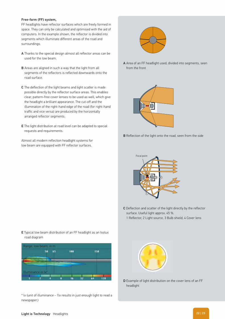
Free-form (FF) system,
FF headlights have reflector surfaces which are freely formed in space. They can only be calculated and optimised with the aid of computers. In the example shown, the reflector is divided into segments which illuminate different areas of the road and surroundings.
A Thanks to the special design almost all reflector areas can be used for the low beam.
B Areas are aligned in such a way that the light from all segments of the reflectors is reflected downwards onto the road surface.
C The deflection of the light beams and light scatter is made possible directly by the reflector surface areas. This enables clear, pattern-free cover lenses to be used as well, which give the headlight a brilliant appearance. The cut-off and the illumination of the right-hand edge of the road (for right-hand traffic and vice versa) are produced by the horizontally arranged reflector segments.
E The light distribution at road level can be adapted to special requests and requirements.
Almost all modern reflection headlight systems for low beam are equipped with FF reflector surfaces.
A Area of an FF headlight used, divided into segments, seen from the front
B Reflection of the light onto the road, seen from the side
D Example of light distribution on the cover lens of an FF headlight
E Typical low beam distribution of an FF headlight as an Isolux road diagram
* lx (unit of illuminance - 1lx results in just enough light to read a newspaper.)
Range, low beam, in m
Illuminance in lx*
C Deflection and scatter of the light directly by the reflector surface. Useful light approx. 45 %. 1 Reflector, 2 Light source, 3 Bulb shield, 4 Cover lens
Focal point
| 23Light is Technology Headlights 22
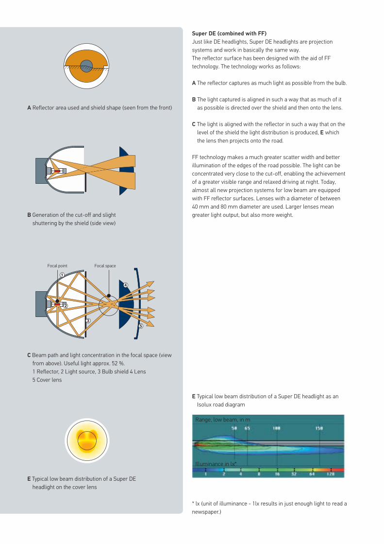
Super DE (combined with FF)
Just like DE headlights, Super DE headlights are projection systems and work in basically the same way. The reflector surface has been designed with the aid of FF technology. The technology works as follows:
A The reflector captures as much light as possible from the bulb.
B The light captured is aligned in such a way that as much of it as possible is directed over the shield and then onto the lens.
C The light is aligned with the reflector in such a way that on the level of the shield the light distribution is produced, E which the lens then projects onto the road.
FF technology makes a much greater scatter width and better illumination of the edges of the road possible. The light can be concentrated very close to the cut-off, enabling the achievement of a greater visible range and relaxed driving at night. Today, almost all new projection systems for low beam are equipped with FF reflector surfaces. Lenses with a diameter of between 40 mm and 80 mm diameter are used. Larger lenses mean greater light output, but also more weight.
A Reflector area used and shield shape (seen from the front)
B Generation of the cut-off and slight shuttering by the shield (side view)
Focal point Focal space
E Typical low beam distribution of a Super DEheadlight on the cover lens
E Typical low beam distribution of a Super DE headlight as an Isolux road diagram
* lx (unit of illuminance - 1lx results in just enough light to read a newspaper.)
Range, low beam, in m
Illuminance in lx*
C Beam path and light concentration in the focal space (view from above). Useful light approx. 52 %. 1 Reflector, 2 Light source, 3 Bulb shield 4 Lens 5 Cover lens
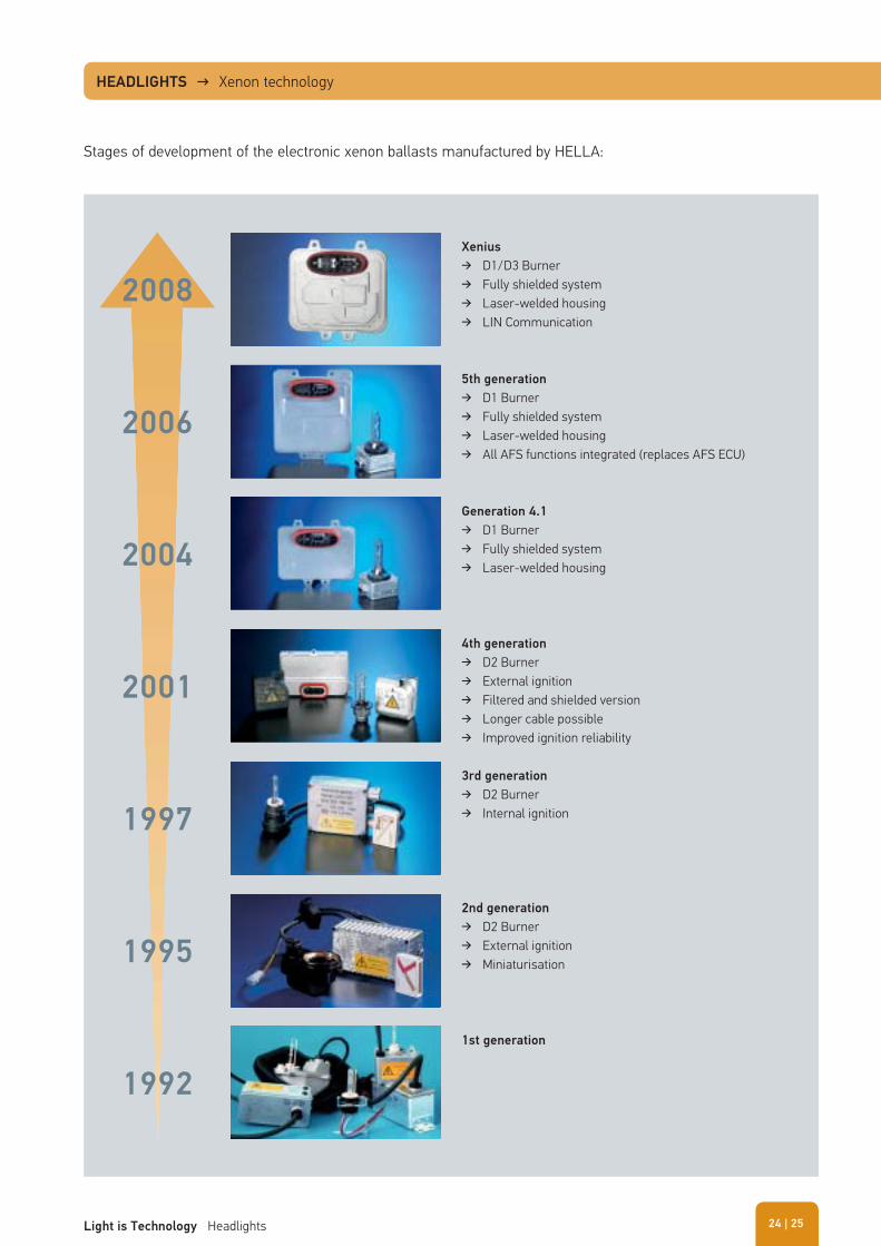
HEADLIGHTS → Xenon technology
Stages of development of the electronic xenon ballasts manufactured by HELLA:
4th generation
� D2 Burner � External ignition � Filtered and shielded version � Longer cable possible � Improved ignition reliability
Generation 4.1
� D1 Burner � Fully shielded system � Laser-welded housing
3rd generation
� D2 Burner � Internal ignition
2008
2006
2004
2001
1997
1995
1992
2nd generation
� D2 Burner � External ignition � Miniaturisation
5th generation
� D1 Burner � Fully shielded system � Laser-welded housing � All AFS functions integrated (replaces AFS ECU)
Xenius
� D1/D3 Burner � Fully shielded system � Laser-welded housing � LIN Communication
1st generation
| 25Light is Technology Headlights 24
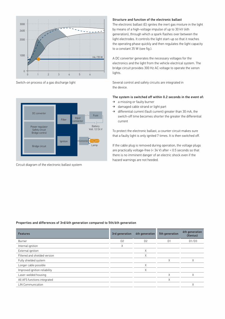
Structure and function of the electronic ballast
The electronic ballast (E) ignites the inert gas mixture in the light by means of a high-voltage impulse of up to 30 kV (4th generation), through which a spark flashes over between the light electrodes. It controls the light start-up so that it reaches the operating phase quickly and then regulates the light capacity to a constant 35 W (see fig.).
A DC converter generates the necessary voltages for the electronics and the light from the vehicle electrical system. The bridge circuit provides 300 Hz AC voltage to operate the xenon lights.
Several control and safety circuits are integrated in the device.
The system is switched off within 0.2 seconds in the event of:
� a missing or faulty burner � damaged cable strand or light part � differential current (fault current) greater than 30 mA, the
switch-off time becomes shorter the greater the differential current
To protect the electronic ballast, a counter circuit makes sure that a faulty light is only ignited 7 times. It is then switched off.
If the cable plug is removed during operation, the voltage plugs are practically voltage-free (< 34 V) after < 0.5 seconds so that there is no imminent danger of an electric shock even if the hazard warnings are not heeded.
Switch-on process of a gas discharge light
Properties and differences of 3rd/4th generation compared to 5th/6th generation
Circuit diagram of the electronic ballast system
Features 3rd generation 4th generation 5th generation6th generation
(Xenius)
Burner D2 D2 D1 D1/D3Internal ignition XExternal ignition XFiltered and shielded version XFully shielded system X XLonger cable possible XImproved ignition reliability XLaser-welded housing X XAll AFS functions integrated XLIN Communication X
3000
2600
2000
1000 H4 / 55 W
00 1 2 3 4 5 6
DC converter
Filter
Ignition Connector
Lamp
BatteryVolt. 12/24 V
Input connector
Fuse
Power regulatorSafety circuit
Bridge control
Bridge circuit
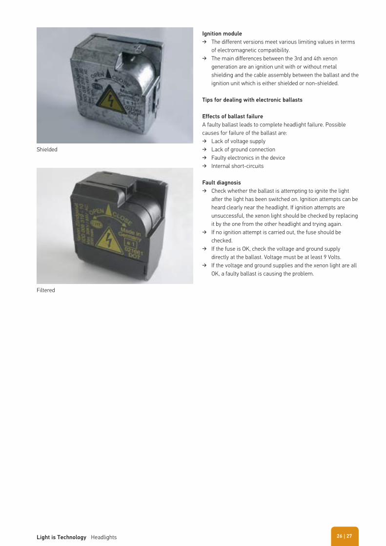
Ignition module
� The different versions meet various limiting values in terms of electromagnetic compatibility.
� The main differences between the 3rd and 4th xenon generation are an ignition unit with or without metal shielding and the cable assembly between the ballast and the ignition unit which is either shielded or non-shielded.
Tips for dealing with electronic ballasts
Effects of ballast failure
A faulty ballast leads to complete headlight failure. Possible causes for failure of the ballast are:
� Lack of voltage supply � Lack of ground connection � Faulty electronics in the device � Internal short-circuits
Fault diagnosis
� Check whether the ballast is attempting to ignite the light after the light has been switched on. Ignition attempts can be heard clearly near the headlight. If ignition attempts are unsuccessful, the xenon light should be checked by replacing it by the one from the other headlight and trying again.
� If no ignition attempt is carried out, the fuse should be checked.
� If the fuse is OK, check the voltage and ground supply directly at the ballast. Voltage must be at least 9 Volts.
� If the voltage and ground supplies and the xenon light are all OK, a faulty ballast is causing the problem.
Shielded
Filtered
| 27Light is Technology Headlights 26
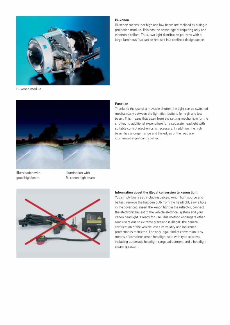
Bi-xenon
Bi-xenon means that high and low beam are realised by a single projection module. This has the advantage of requiring only one electronic ballast. Thus, two light distribution patterns with a large luminous flux can be realised in a confined design space.
Function
Thanks to the use of a movable shutter, the light can be switched mechanically between the light distributions for high and low beam. This means that apart from the setting mechanism for the shutter, no additional expenditure for a separate headlight with suitable control electronics is necessary. In addition, the high beam has a longer range and the edges of the road are illuminated significantly better.
Information about the illegal conversion to xenon light
You simply buy a set, including cables, xenon light source and ballast, remove the halogen bulb from the headlight, saw a hole in the cover cap, insert the xenon light in the reflector, connect the electronic ballast to the vehicle electrical system and your xenon headlight is ready for use. This method endangers other road users due to extreme glare and is illegal. The general certification of the vehicle loses its validity and insurance protection is restricted. The only legal kind of conversion is by means of complete xenon headlight sets with type approval, including automatic headlight range adjustment and a headlight cleaning system.
Bi-xenon module
Illumination with good high beam
Illumination with Bi-xenon high beam
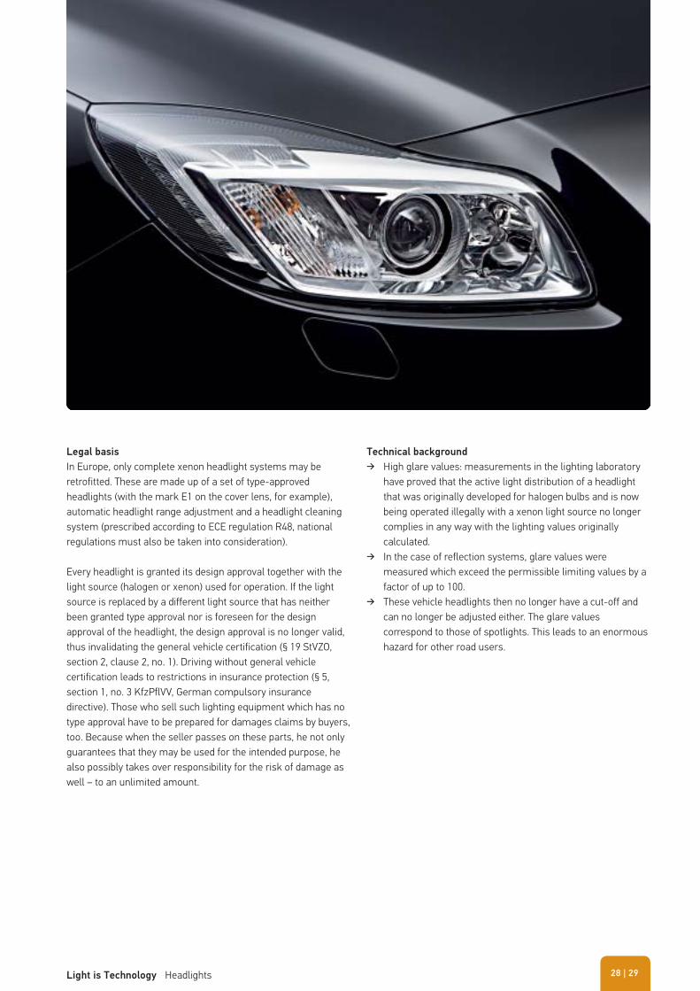
Legal basis
In Europe, only complete xenon headlight systems may be retrofitted. These are made up of a set of type-approved headlights (with the mark E1 on the cover lens, for example), automatic headlight range adjustment and a headlight cleaning system (prescribed according to ECE regulation R48, national regulations must also be taken into consideration).
Every headlight is granted its design approval together with the light source (halogen or xenon) used for operation. If the light source is replaced by a different light source that has neither been granted type approval nor is foreseen for the design approval of the headlight, the design approval is no longer valid, thus invalidating the general vehicle certification (§ 19 StVZO, section 2, clause 2, no. 1). Driving without general vehicle certification leads to restrictions in insurance protection (§ 5, section 1, no. 3 KfzPflVV, German compulsory insurance directive). Those who sell such lighting equipment which has no type approval have to be prepared for damages claims by buyers, too. Because when the seller passes on these parts, he not only guarantees that they may be used for the intended purpose, he also possibly takes over responsibility for the risk of damage as well – to an unlimited amount.
Technical background
� High glare values: measurements in the lighting laboratory have proved that the active light distribution of a headlight that was originally developed for halogen bulbs and is now being operated illegally with a xenon light source no longer complies in any way with the lighting values originally calculated.
� In the case of reflection systems, glare values were measured which exceed the permissible limiting values by a factor of up to 100.
� These vehicle headlights then no longer have a cut-off and can no longer be adjusted either. The glare values correspond to those of spotlights. This leads to an enormous hazard for other road users.
| 29Light is Technology Headlights 28
Whether in car magazines, tuning brochures or on the internet: daytime running lights are currently much discussed and praised. Besides being offered as optional equipment in new cars by the manufacturer, there are also many retrofitting solutions in the independent aftermarket . Be careful, though! Among the numerous suppliers, there are also some black sheep, whose sets do not fulfil legal requirements. Therefore, it is important to study this topic carefully.
HEADLIGHTS → Daytime running light
Why should I get daytime running lights, and what are the
advantages?
� Better perception of the vehicle by other road users � More time for other road users to react � Daytime running lights switch on automatically
The basic function of the daytime running lights is to make a vehicle more visible to other road users, This is particularly important in situations with changing lighting conditions, e.g. when driving through a forest.
Another advantage is that other road users gain more response time, as they can see a vehicle more clearly and quickly. The fact that the daytime running lights are automatically activated when the ignition is turned on makes them easy to use. It is therefore impossible to forget to turn them on.
What are the disadvantages of regular low beam lights
compared to daytime running lights?
� Increased fuel consumption, as all headlights and lamps are on all the time. Light is expensive, as headlights and rear lights need electricity and therefore consume fuel! For a normal car with petrol engine, turning the light on means an additional consumption of 0.207 litres per 100 km. Based on a mileage of 30,000 km per year, this approximately adds up to an extra 60 litres. Consequently, the exhaust emissions are increased accordingly.
� The replacement rate of bulbs is significantly increased: Switching the lights on permanently increases the wear and tear of bulbs. The service life of standard versions of H7 and H4 halogen bulbs (no + 50 % or long-life bulbs) lies between 550 and 700 hours. In case of continual operation, the replacement rate of bulbs is significantly increased. An LED daytime running light, on the other hand, has a service life of 10,000 hours and usually lasts as long as the car.
� Besides the material costs, there are the sometimes considerable costs of the bulb replacement. In some cars, the bulb replacement takes a great deal of effort, as battery, air filter housing, headlights, etc. must be removed first.
� The warning effect of low beam lights is smaller than that of special daytime running lights. Low beam lights typically are set to provide an optimal lighting of the road in darkness. The emitted light "descends" evenly, in order to avoid dazzling oncoming traffic. Daytime running lights, on the other hand, are designed to achieve and optimal and early perception of the car during the day. Their light intensity is limited (2 Lux at a distance of 25 m) so that the emitted light is not perceived as dazzling.
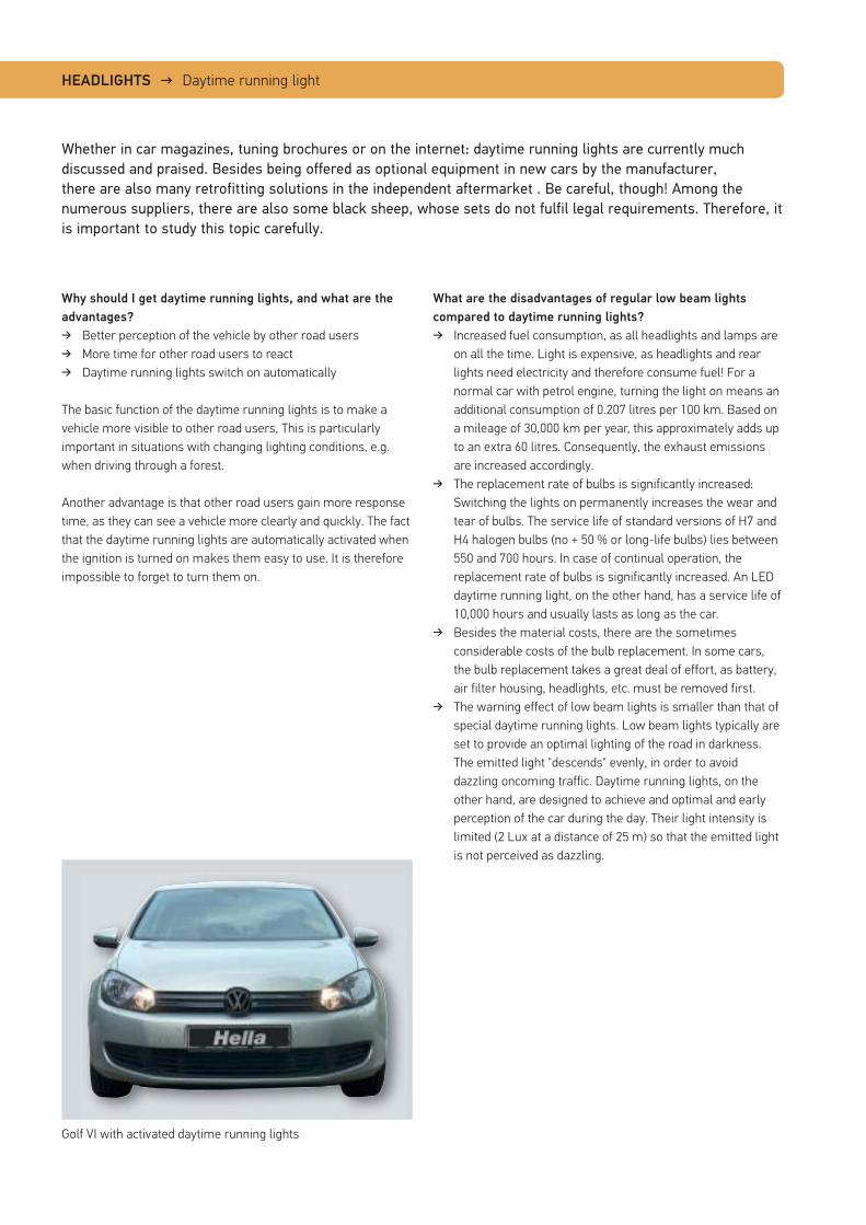
Golf VI with activated daytime running lights
The market offers installation kits with electronic
components that only turn on the low beam lights.
Is that an alternative to daytime running lights?
Compared to driving without lights, this may be a step in the right direction. However, as explained above, daytime running lights offer clearly superior visibility and energy savings. Some of these electronic kits also dim the low beam, in the case of one manufacturer even by about 50 %. This means that the luminous flux, i.e. the total volume of light that is radiated by a light source, is reduced so much that it falls below the required minimum value. This is absolutely prohibited by law!
The reason: Headlights receive their type approval for form, bulb and function. Daytime running lights generated with the aid of electronics thus mean an additional lighting function which was not considered during type approval. Therefore, the headlight automatically loses its certification!
What should you consider when choosing daytime running
lights?
Generally, daytime running lights must be road legal. Therefore, they must fulfil the specifications according to ECE-R87. Once the light passes the so-called type approval, the approval is granted. Generally, the approval mark can be found on the lens or the housing.
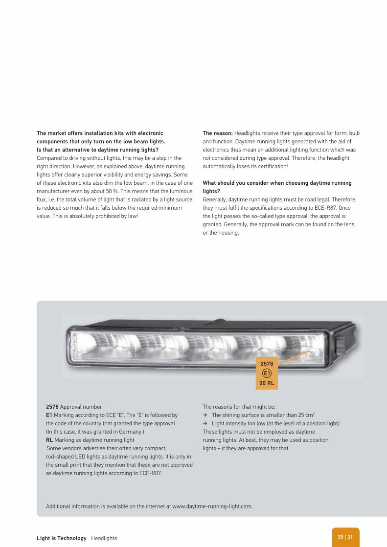
2578 Approval numberE1 Marking according to ECE "E". The "E" is followed by the code of the country that granted the type approval. (In this case, it was granted in Germany.)RL Marking as daytime running light Some vendors advertise their often very compact, rod-shaped LED lights as daytime running lights. It is only in the small print that they mention that these are not approved as daytime running lights according to ECE-R87.
The reasons for that might be: � The shining surface is smaller than 25 cm2
� Light intensity too low (at the level of a position light)These lights must not be employed as daytime running lights. At best, they may be used as position lights – if they are approved for that.
Additional information is available on the internet at www.daytime-running-light.com.
2578
00 RL
E1
| 31Light is Technology Headlights 30
HEADLIGHTS → Headlight range adjustment
Safe driving in the dark is only possible with headlights where the angle of inclination is always set correctly. With the manual headlight range adjustment compulsory in Europe today for halogen headlights, the driver has the possibility of adapting headlight inclination to the respective load using a switch on the dashboard. Inclination adjustment is usually by means of an electromotive actuator. The subsequently developed automatic
headlight range adjustment systems adapt the angle of inclination of the headlights to the vehicle's road holding without the driver having to intervene. As already mentioned, the legislator prescribes such systems for xenon headlights.
Manual adjustment
With this system the driver has to adjust the inclination of the headlight himself by means of a switch. There are pneumatic and electrical systems available.
The problem with this is that many loaded vehicles dazzle oncoming traffic since drivers are not well informed enough about the adjustment possibilities and their function on their vehicle.
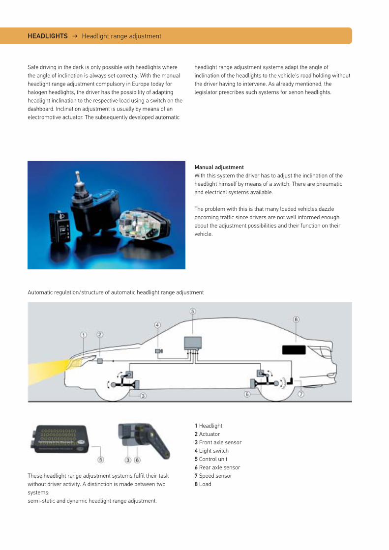
1 Headlight2 Actuator3 Front axle sensor4 Light switch5 Control unit6 Rear axle sensor7 Speed sensor8 Load
These headlight range adjustment systems fulfil their task without driver activity. A distinction is made between two systems: semi-static and dynamic headlight range adjustment.
Automatic regulation/structure of automatic headlight range adjustment
Semi-static headlight range adjustment
This headlight range adjustment system only corrects changes in headlight inclination due to changes in load status. A control unit evaluates the data from the front and rear axle sensors, compares this with the stored reference data and triggers the actuator motors on the headlights accordingly. Usually the same type of actuator motors are used as for manual headlight range adjustment. In the case of compact vehicles without long wheel overhang, this system offers the possibility of doing without the front axle sensor since the changes in inclination mainly occur on the rear axle only. In addition, semi-static headlight range adjustment works with great vibration damping, i.e. it only triggers inclinations in the bodywork that last for a relatively long time. In HELLA's xenon conversion sets an ultrasound system is used. Here, the sensor measures the direct distance to the roadway.
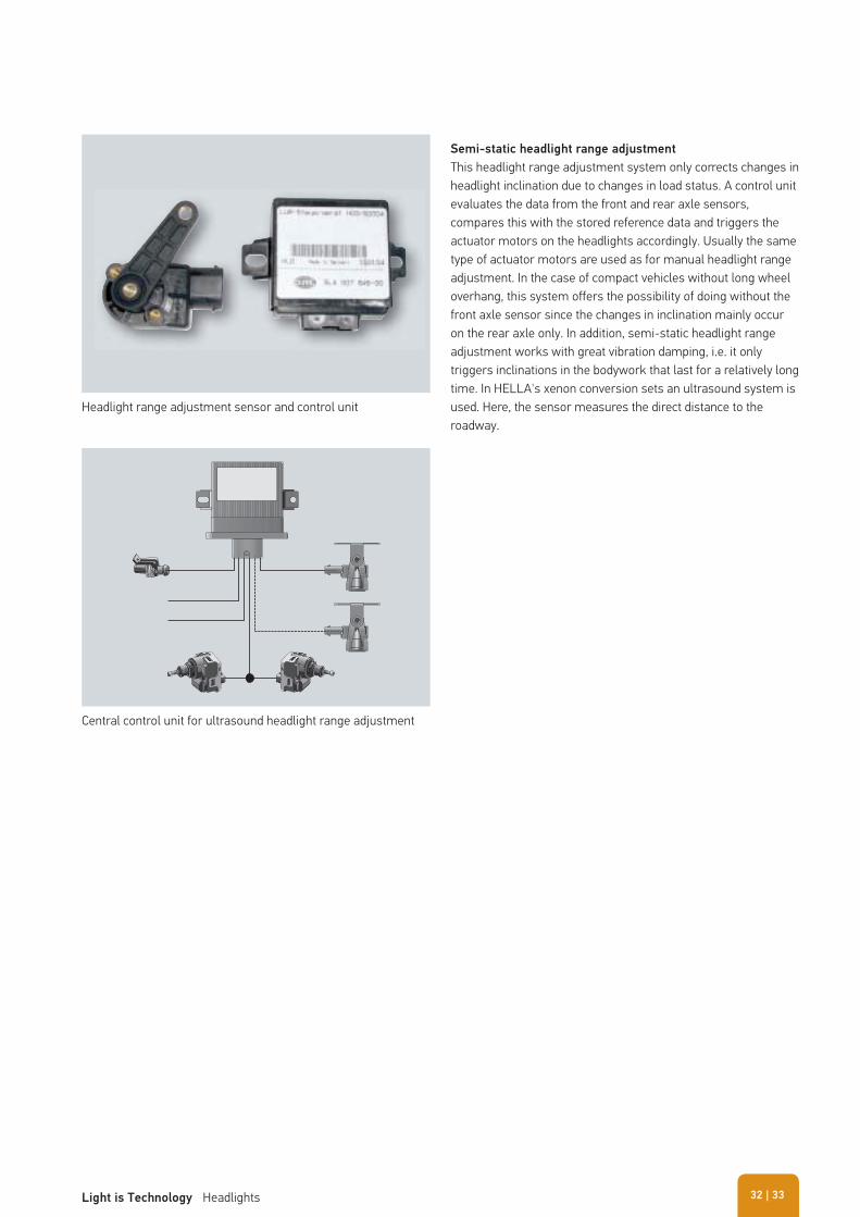
Headlight range adjustment sensor and control unit
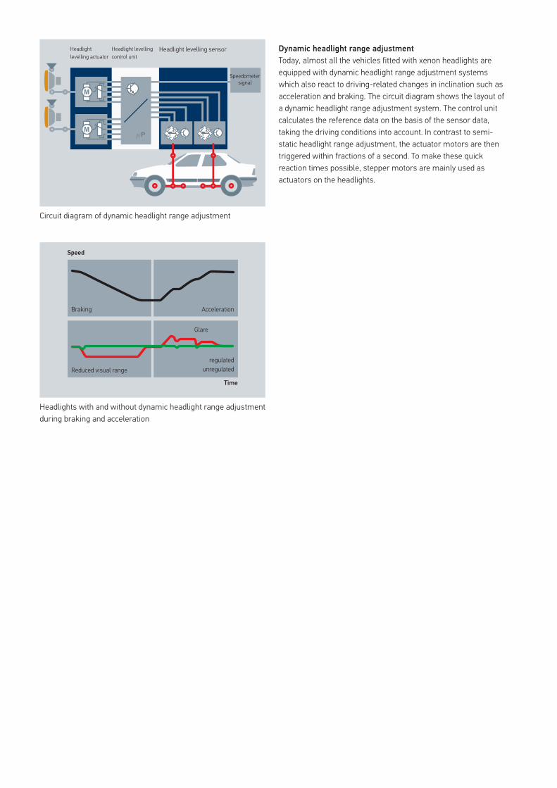
Central control unit for ultrasound headlight range adjustment
| 33Light is Technology Headlights 32
Dynamic headlight range adjustment
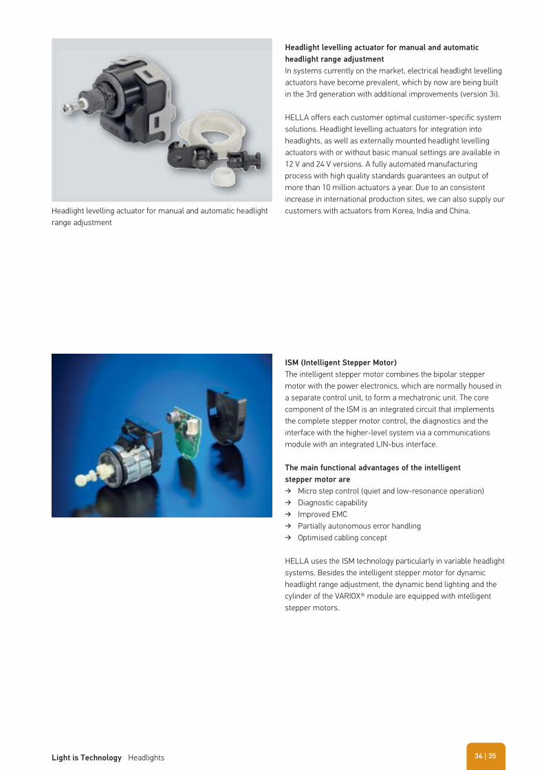
Today, almost all the vehicles fitted with xenon headlights are equipped with dynamic headlight range adjustment systems which also react to driving-related changes in inclination such as acceleration and braking. The circuit diagram shows the layout of a dynamic headlight range adjustment system. The control unit calculates the reference data on the basis of the sensor data, taking the driving conditions into account. In contrast to semi-static headlight range adjustment, the actuator motors are then triggered within fractions of a second. To make these quick reaction times possible, stepper motors are mainly used as actuators on the headlights.
Circuit diagram of dynamic headlight range adjustment
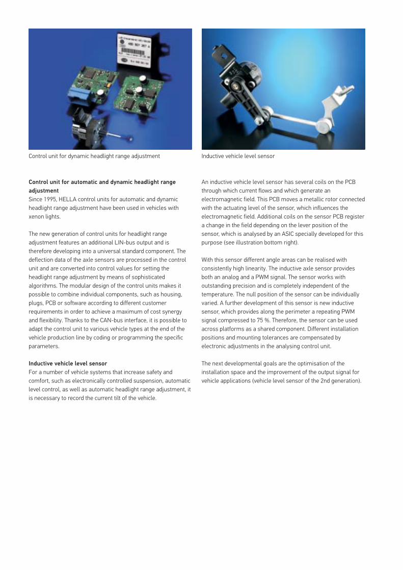
Speed
Braking
Reduced visual range
Acceleration
Glare
regulatedunregulated
Time
Headlight levelling actuator
Speedometer signal
Headlight levelling control unit
Headlight levelling sensor
Headlights with and without dynamic headlight range adjustment during braking and acceleration
Headlight levelling actuator for manual and automatic
headlight range adjustment
In systems currently on the market, electrical headlight levelling actuators have become prevalent, which by now are being built in the 3rd generation with additional improvements (version 3i).
HELLA offers each customer optimal customer-specific system solutions. Headlight levelling actuators for integration into headlights, as well as externally mounted headlight levelling actuators with or without basic manual settings are available in 12 V and 24 V versions. A fully automated manufacturing process with high quality standards guarantees an output of more than 10 million actuators a year. Due to an consistent increase in international production sites, we can also supply our customers with actuators from Korea, India and China.
ISM (Intelligent Stepper Motor)
The intelligent stepper motor combines the bipolar stepper motor with the power electronics, which are normally housed in a separate control unit, to form a mechatronic unit. The core component of the ISM is an integrated circuit that implements the complete stepper motor control, the diagnostics and the interface with the higher-level system via a communications module with an integrated LIN-bus interface.
The main functional advantages of the intelligent
stepper motor are
� Micro step control (quiet and low-resonance operation) � Diagnostic capability � Improved EMC � Partially autonomous error handling � Optimised cabling concept
HELLA uses the ISM technology particularly in variable headlight systems. Besides the intelligent stepper motor for dynamic headlight range adjustment, the dynamic bend lighting and the cylinder of the VARIOX® module are equipped with intelligent stepper motors.
Headlight levelling actuator for manual and automatic headlight range adjustment
| 35Light is Technology Headlights 34
Control unit for automatic and dynamic headlight range
adjustment
Since 1995, HELLA control units for automatic and dynamic headlight range adjustment have been used in vehicles with xenon lights.
The new generation of control units for headlight range adjustment features an additional LIN-bus output and is therefore developing into a universal standard component. The deflection data of the axle sensors are processed in the control unit and are converted into control values for setting the headlight range adjustment by means of sophisticated algorithms. The modular design of the control units makes it possible to combine individual components, such as housing, plugs, PCB or software according to different customer requirements in order to achieve a maximum of cost synergy and flexibility. Thanks to the CAN-bus interface, it is possible to adapt the control unit to various vehicle types at the end of the vehicle production line by coding or programming the specific parameters.
Inductive vehicle level sensor
For a number of vehicle systems that increase safety and comfort, such as electronically controlled suspension, automatic level control, as well as automatic headlight range adjustment, it is necessary to record the current tilt of the vehicle.
Control unit for dynamic headlight range adjustment Inductive vehicle level sensor
An inductive vehicle level sensor has several coils on the PCB through which current flows and which generate an electromagnetic field. This PCB moves a metallic rotor connected with the actuating level of the sensor, which influences the electromagnetic field. Additional coils on the sensor PCB register a change in the field depending on the lever position of the sensor, which is analysed by an ASIC specially developed for this purpose (see illustration bottom right).
With this sensor different angle areas can be realised with consistently high linearity. The inductive axle sensor provides both an analog and a PWM signal. The sensor works with outstanding precision and is completely independent of the temperature. The null position of the sensor can be individually varied. A further development of this sensor is new inductive sensor, which provides along the perimeter a repeating PWM signal compressed to 75 %. Therefore, the sensor can be used across platforms as a shared component. Different installation positions and mounting tolerances are compensated by electronic adjustments in the analysing control unit.
The next developmental goals are the optimisation of the installation space and the improvement of the output signal for vehicle applications (vehicle level sensor of the 2nd generation).
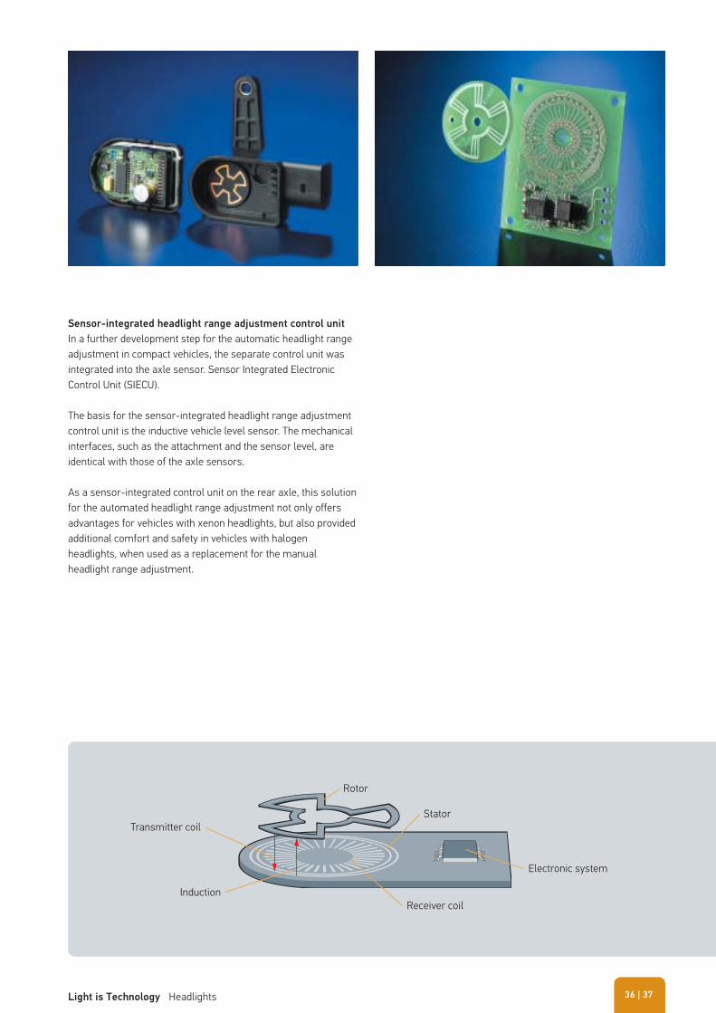
Sensor-integrated headlight range adjustment control unit
In a further development step for the automatic headlight range adjustment in compact vehicles, the separate control unit was integrated into the axle sensor. Sensor Integrated Electronic Control Unit (SIECU).
The basis for the sensor-integrated headlight range adjustment control unit is the inductive vehicle level sensor. The mechanical interfaces, such as the attachment and the sensor level, are identical with those of the axle sensors.
As a sensor-integrated control unit on the rear axle, this solution for the automated headlight range adjustment not only offers advantages for vehicles with xenon headlights, but also provided additional comfort and safety in vehicles with halogen headlights, when used as a replacement for the manual headlight range adjustment.
Transmitter coil
Rotor
Stator
Receiver coil
Electronic system
Induction
| 37Light is Technology Headlights 36
Opel/Vauxhall Signum 3.2i V6
km/h
v
v
Tips for dealing with headlight range adjustment systems
If there is an electrical fault in the headlight range adjustment during driving, the headlights remain in this position. In other vehicles, though, the headlights are moved to the home position and stay there. The driver is alerted about the error in any case by a signal lamp or a text message in the cockpit.
System failure can be caused by the following
� Servomotors on the headlights are faulty � Headlight range adjustment sensor for vehicle level is faulty � Control unit has been replaced and not coded � Headlights have not been set (basic adjustment) � Control unit faulty � Interrupted data cable � No voltage supply � Mechanical damage
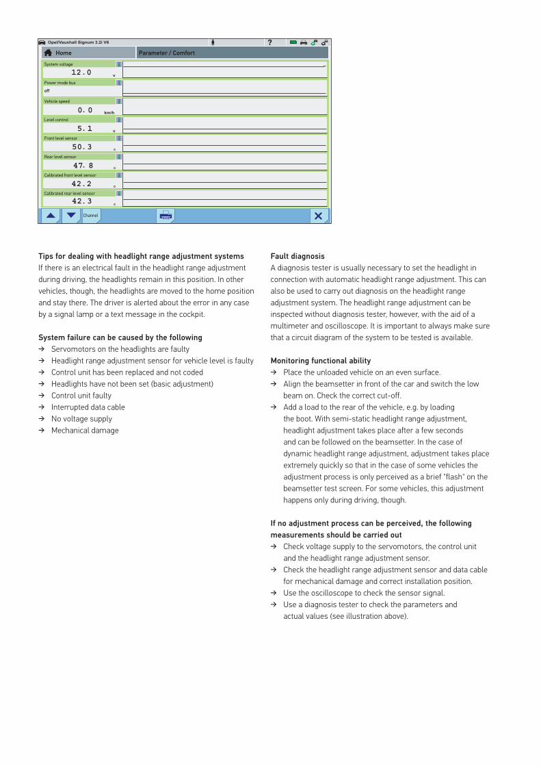
Fault diagnosis
A diagnosis tester is usually necessary to set the headlight in connection with automatic headlight range adjustment. This can also be used to carry out diagnosis on the headlight range adjustment system. The headlight range adjustment can be inspected without diagnosis tester, however, with the aid of a multimeter and oscilloscope. It is important to always make sure that a circuit diagram of the system to be tested is available.
Monitoring functional ability
� Place the unloaded vehicle on an even surface. � Align the beamsetter in front of the car and switch the low
beam on. Check the correct cut-off. � Add a load to the rear of the vehicle, e.g. by loading
the boot. With semi-static headlight range adjustment, headlight adjustment takes place after a few seconds and can be followed on the beamsetter. In the case of dynamic headlight range adjustment, adjustment takes place extremely quickly so that in the case of some vehicles the adjustment process is only perceived as a brief "flash" on the beamsetter test screen. For some vehicles, this adjustment happens only during driving, though.
If no adjustment process can be perceived, the following
measurements should be carried out
� Check voltage supply to the servomotors, the control unit and the headlight range adjustment sensor.
� Check the headlight range adjustment sensor and data cable for mechanical damage and correct installation position.
� Use the oscilloscope to check the sensor signal. � Use a diagnosis tester to check the parameters and
actual values (see illustration above).
System voltage
Home Parameter / Comfort
Power mode bus
Vehicle speed
Level control
Front level sensor
Rear level sensor
Calibrated front level sensor
Calibrated rear level sensor
Channel
off
Dynamic bend lighting
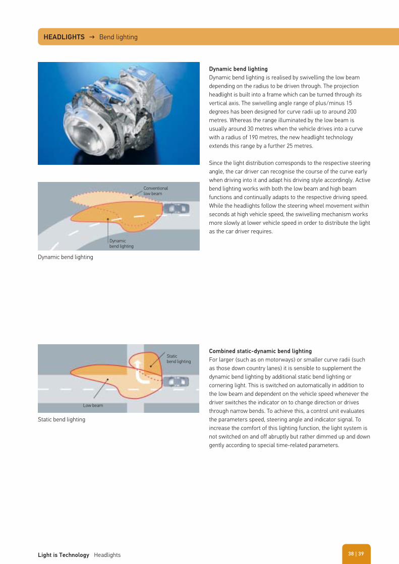
Dynamic bend lighting is realised by swivelling the low beam depending on the radius to be driven through. The projection headlight is built into a frame which can be turned through its vertical axis. The swivelling angle range of plus/minus 15 degrees has been designed for curve radii up to around 200 metres. Whereas the range illuminated by the low beam is usually around 30 metres when the vehicle drives into a curve with a radius of 190 metres, the new headlight technology extends this range by a further 25 metres.
Since the light distribution corresponds to the respective steering angle, the car driver can recognise the course of the curve early when driving into it and adapt his driving style accordingly. Active bend lighting works with both the low beam and high beam functions and continually adapts to the respective driving speed. While the headlights follow the steering wheel movement within seconds at high vehicle speed, the swivelling mechanism works more slowly at lower vehicle speed in order to distribute the light as the car driver requires.
Combined static-dynamic bend lighting
For larger (such as on motorways) or smaller curve radii (such as those down country lanes) it is sensible to supplement the dynamic bend lighting by additional static bend lighting or cornering light. This is switched on automatically in addition to the low beam and dependent on the vehicle speed whenever the driver switches the indicator on to change direction or drives through narrow bends. To achieve this, a control unit evaluates the parameters speed, steering angle and indicator signal. To increase the comfort of this lighting function, the light system is not switched on and off abruptly but rather dimmed up and down gently according to special time-related parameters.
Dynamic bend lighting
Static bend lighting
Dynamic bend lighting
Low beam
Conventionallow beam
Staticbend lighting
HEADLIGHTS → Bend lighting
| 39Light is Technology Headlights 38
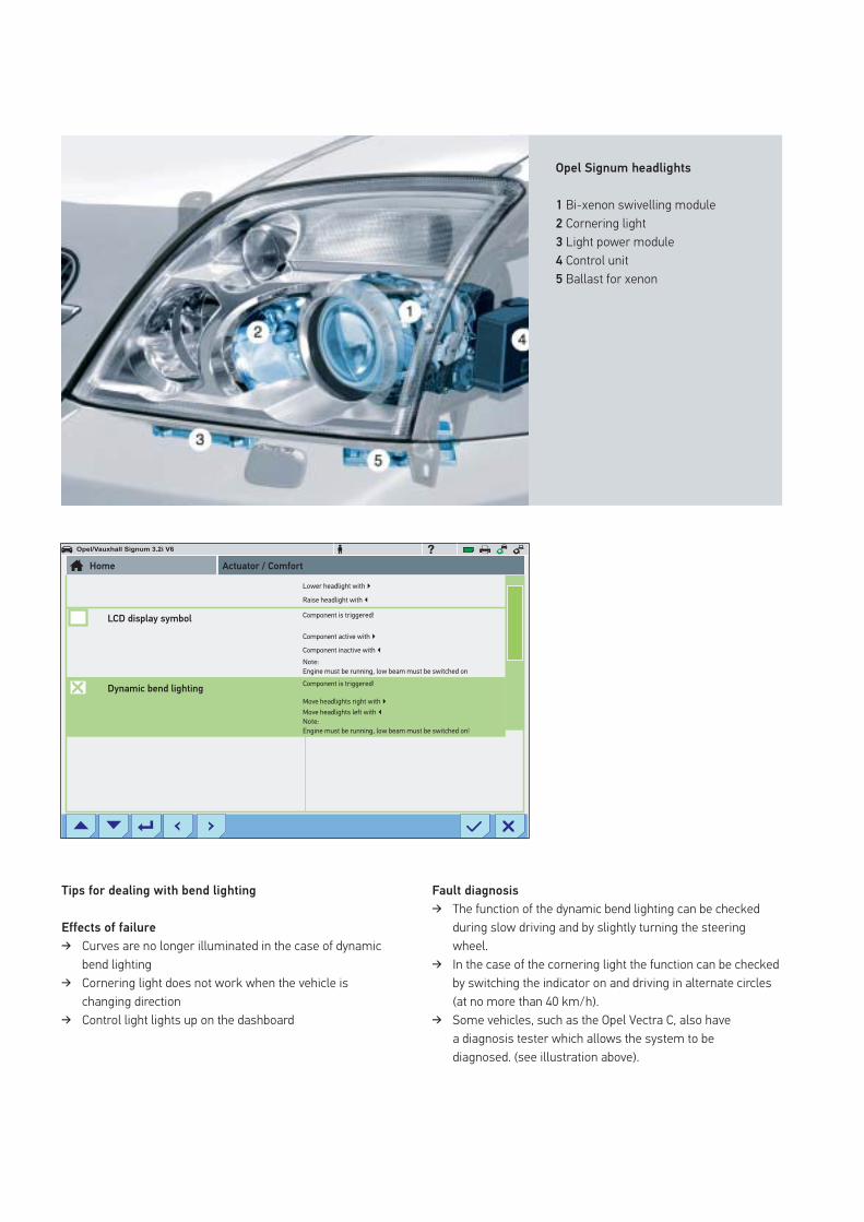
Opel Signum headlights
1 Bi-xenon swivelling module2 Cornering light3 Light power module4 Control unit5 Ballast for xenon
Tips for dealing with bend lighting
Effects of failure
� Curves are no longer illuminated in the case of dynamic bend lighting
� Cornering light does not work when the vehicle is changing direction
� Control light lights up on the dashboard
Opel/Vauxhall Signum 3.2i V6
Fault diagnosis
� The function of the dynamic bend lighting can be checked during slow driving and by slightly turning the steering wheel.
� In the case of the cornering light the function can be checked by switching the indicator on and driving in alternate circles (at no more than 40 km/h).
� Some vehicles, such as the Opel Vectra C, also have a diagnosis tester which allows the system to be diagnosed. (see illustration above).
Lower headlight with �
Raise headlight with �
Component is triggered!
Component active with �
Component inactive with �Note:
Note:
Engine must be running, low beam must be switched on
Engine must be running, low beam must be switched on!
Component is triggered!
Move headlights right with �Move headlights left with �
Home
LCD display symbol
Dynamic bend lighting
Actuator / Comfort
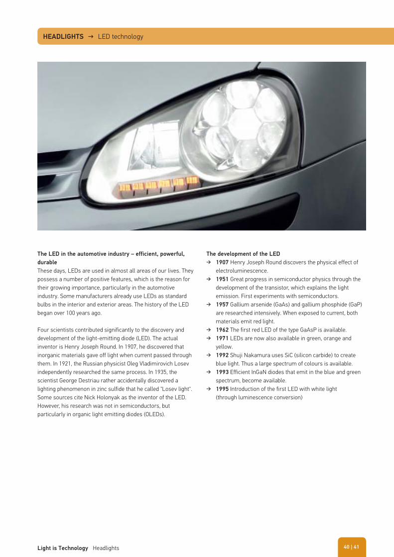
The LED in the automotive industry – efficient, powerful,
durable
These days, LEDs are used in almost all areas of our lives. They possess a number of positive features, which is the reason for their growing importance, particularly in the automotive industry. Some manufacturers already use LEDs as standard bulbs in the interior and exterior areas. The history of the LED began over 100 years ago.
Four scientists contributed significantly to the discovery and development of the light-emitting diode (LED). The actual inventor is Henry Joseph Round. In 1907, he discovered that inorganic materials gave off light when current passed through them. In 1921, the Russian physicist Oleg Vladimirovich Losev independently researched the same process. In 1935, the scientist George Destriau rather accidentally discovered a lighting phenomenon in zinc sulfide that he called "Losev light". Some sources cite Nick Holonyak as the inventor of the LED. However, his research was not in semiconductors, but particularly in organic light emitting diodes (OLEDs).
HEADLIGHTS → LED technology
The development of the LED
� 1907 Henry Joseph Round discovers the physical effect of electroluminescence.
� 1951 Great progress in semiconductor physics through the development of the transistor, which explains the light emission. First experiments with semiconductors.
� 1957 Gallium arsenide (GaAs) and gallium phosphide (GaP) are researched intensively. When exposed to current, both materials emit red light.
� 1962 The first red LED of the type GaAsP is available. � 1971 LEDs are now also available in green, orange and
yellow. � 1992 Shuji Nakamura uses SiC (silicon carbide) to create
blue light. Thus a large spectrum of colours is available. � 1993 Efficient InGaN diodes that emit in the blue and green
spectrum, become available. � 1995 Introduction of the first LED with white light
(through luminescence conversion)
| 41Light is Technology Headlights 40
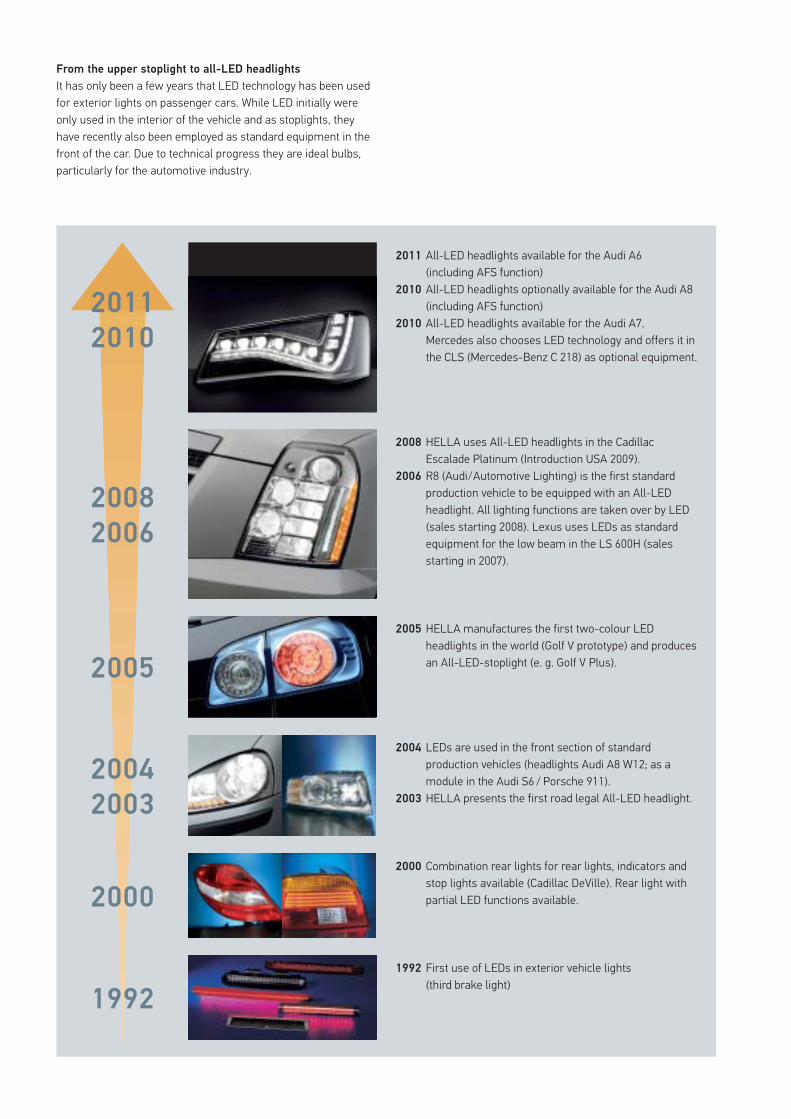
From the upper stoplight to all-LED headlights
It has only been a few years that LED technology has been used for exterior lights on passenger cars. While LED initially were only used in the interior of the vehicle and as stoplights, they have recently also been employed as standard equipment in the front of the car. Due to technical progress they are ideal bulbs, particularly for the automotive industry.
2005 HELLA manufactures the first two-colour LED headlights in the world (Golf V prototype) and produces an All-LED-stoplight (e. g. Golf V Plus).
2004 LEDs are used in the front section of standard production vehicles (headlights Audi A8 W12; as a module in the Audi S6 / Porsche 911).
2003 HELLA presents the first road legal All-LED headlight.
2008
2006
2005
2004
2003
2000
1992
2000 Combination rear lights for rear lights, indicators and stop lights available (Cadillac DeVille). Rear light with partial LED functions available.
2008 HELLA uses All-LED headlights in the Cadillac Escalade Platinum (Introduction USA 2009).
2006 R8 (Audi/Automotive Lighting) is the first standard production vehicle to be equipped with an All-LED headlight. All lighting functions are taken over by LED (sales starting 2008). Lexus uses LEDs as standard equipment for the low beam in the LS 600H (sales starting in 2007).
2011 All-LED headlights available for the Audi A6 (including AFS function)
2010 All-LED headlights optionally available for the Audi A8 (including AFS function)
2010 All-LED headlights available for the Audi A7.Mercedes also chooses LED technology and offers it in the CLS (Mercedes-Benz C 218) as optional equipment.
1992 First use of LEDs in exterior vehicle lights (third brake light)
2011
2010
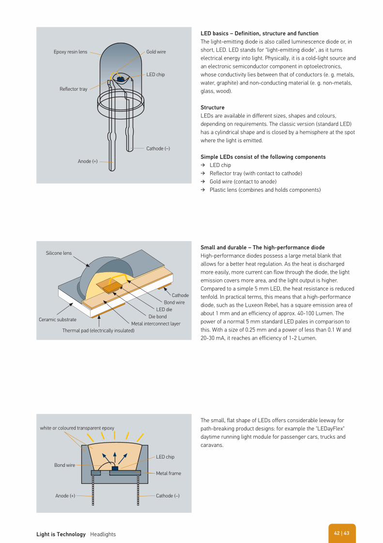
LED basics – Definition, structure and function
The light-emitting diode is also called luminescence diode or, in short, LED. LED stands for "light-emitting diode", as it turns electrical energy into light. Physically, it is a cold-light source and an electronic semiconductor component in optoelectronics, whose conductivity lies between that of conductors (e. g. metals, water, graphite) and non-conducting material (e. g. non-metals, glass, wood).
Structure
LEDs are available in different sizes, shapes and colours, depending on requirements. The classic version (standard LED) has a cylindrical shape and is closed by a hemisphere at the spot where the light is emitted.
Simple LEDs consist of the following components
� LED chip � Reflector tray (with contact to cathode) � Gold wire (contact to anode) � Plastic lens (combines and holds components)
Small and durable – The high-performance diode
High-performance diodes possess a large metal blank that allows for a better heat regulation. As the heat is discharged more easily, more current can flow through the diode, the light emission covers more area, and the light output is higher. Compared to a simple 5 mm LED, the heat resistance is reduced tenfold. In practical terms, this means that a high-performance diode, such as the Luxeon Rebel, has a square emission area of about 1 mm and an efficiency of approx. 40-100 Lumen. The power of a normal 5 mm standard LED pales in comparison to this. With a size of 0.25 mm and a power of less than 0.1 W and 20-30 mA, it reaches an efficiency of 1-2 Lumen.
Anode (+)
Cathode (–)
Gold wire
LED chip
Reflector tray
Epoxy resin lens
LED chip
Metal frame
Cathode (–)Anode (+)
Bond wire
white or coloured transparent epoxyThe small, flat shape of LEDs offers considerable leeway for path-breaking product designs: for example the "LEDayFlex" daytime running light module for passenger cars, trucks and caravans.
CathodeBond wire
LED dieDie bond
Metal interconnect layerCeramic substrate
Silicone lens
Thermal pad (electrically insulated)
| 43Light is Technology Headlights 42
Designs
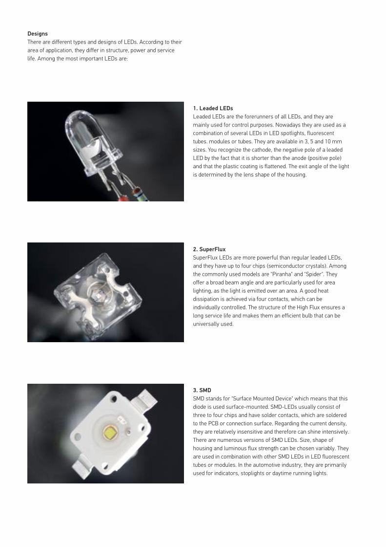
There are different types and designs of LEDs. According to their area of application, they differ in structure, power and service life. Among the most important LEDs are:
1. Leaded LEDs
Leaded LEDs are the forerunners of all LEDs, and they are mainly used for control purposes. Nowadays they are used as a combination of several LEDs in LED spotlights, fluorescent tubes. modules or tubes. They are available in 3, 5 and 10 mm sizes. You recognize the cathode, the negative pole of a leaded LED by the fact that it is shorter than the anode (positive pole) and that the plastic coating is flattened. The exit angle of the light is determined by the lens shape of the housing.
2. SuperFlux
SuperFlux LEDs are more powerful than regular leaded LEDs, and they have up to four chips (semiconductor crystals). Among the commonly used models are "Piranha" and "Spider". They offer a broad beam angle and are particularly used for area lighting, as the light is emitted over an area. A good heat dissipation is achieved via four contacts, which can be individually controlled. The structure of the High Flux ensures a long service life and makes them an efficient bulb that can be universally used.
3. SMD
SMD stands for "Surface Mounted Device" which means that this diode is used surface-mounted. SMD-LEDs usually consist of three to four chips and have solder contacts, which are soldered to the PCB or connection surface. Regarding the current density, they are relatively insensitive and therefore can shine intensively. There are numerous versions of SMD LEDs. Size, shape of housing and luminous flux strength can be chosen variably. They are used in combination with other SMD LEDs in LED fluorescent tubes or modules. In the automotive industry, they are primarily used for indicators, stoplights or daytime running lights.
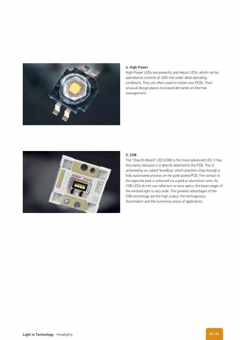
4. High Power
High Power LEDs are powerful and robust LEDs, which can be operated at currents of 1000 mA under ideal operating conditions. They are often used on metal-core PCBs. Their unusual design places increased demands on thermal management.
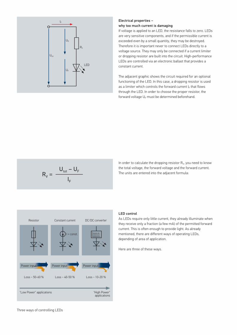
5. COB
The "Chip On Board" LED (COB) is the most advanced LED. It has this name, because it is directly attached to the PCB. This is achieved by so-called "bundling" which attaches chips though a fully automated process on the gold-plated PCB. The contact to the opposite pole is achieved via a gold or aluminium wire. As COB LEDs do not use reflectors or lens optics, the beam angle of the emitted light is very wide. The greatest advantages of the COB technology are the high output, the homogenous illumination and the numerous areas of application.
| 45Light is Technology Headlights 44
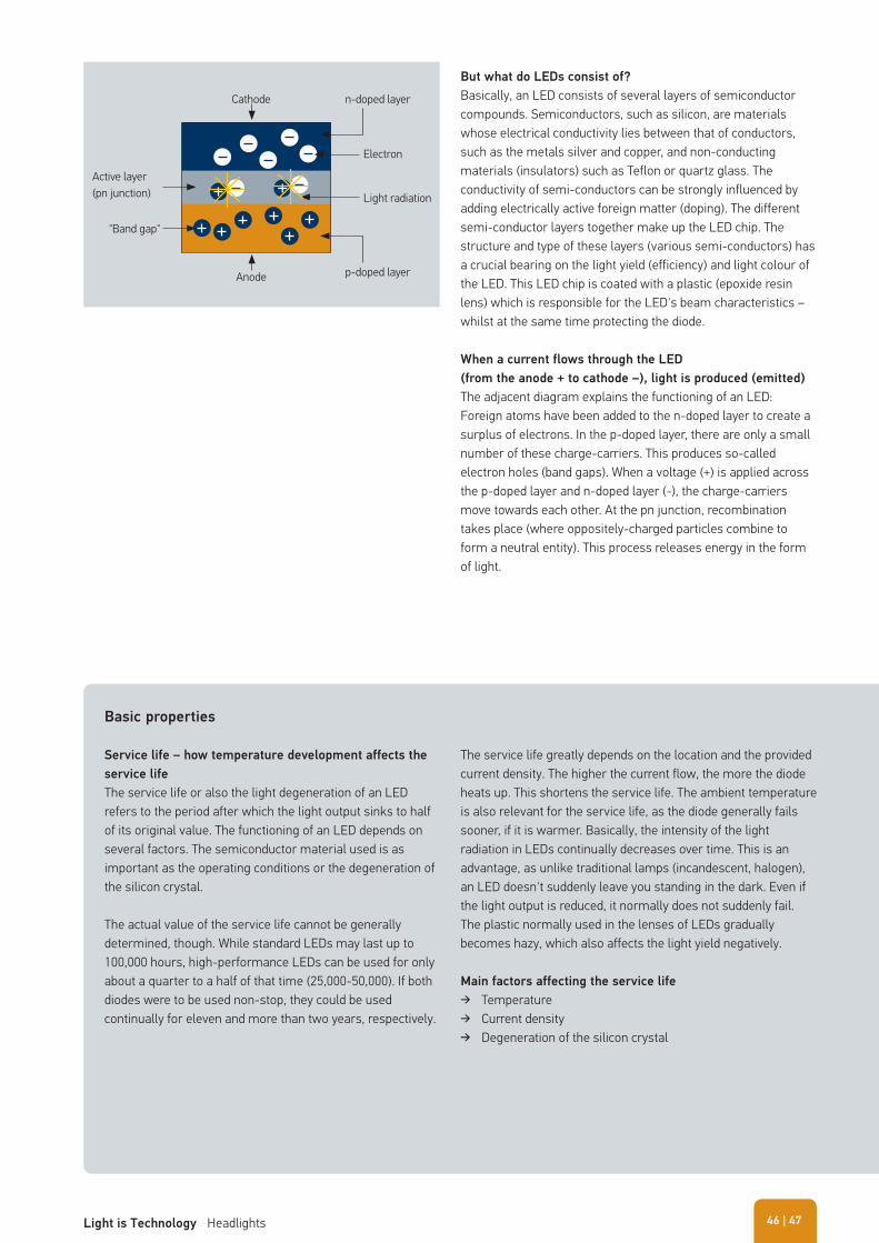
Electrical properties –
why too much current is damaging If voltage is applied to an LED, the resistance falls to zero. LEDs are very sensitive components, and if the permissible current is exceeded even by a small quantity, they may be destroyed. Therefore it is important never to connect LEDs directly to a voltage source. They may only be connected if a current limiter or dropping resistor are built into the circuit. High-performance LEDs are controlled via an electronic ballast that provides a constant current.
The adjacent graphic shows the circuit required for an optional functioning of the LED. In this case, a dropping resistor is used as a limiter which controls the forward current IF that flows through the LED. In order to choose the proper resistor, the forward voltage UF must be determined beforehand.
In order to calculate the dropping resistor RV, you need to know the total voltage, the forward voltage and the forward current. The units are entered into the adjacent formula:
LED control
As LEDs require only little current, they already illuminate when they receive only a fraction (a few mA) of the permitted forward current. This is often enough to provide light. As already mentioned, there are different ways of operating LEDs, depending of area of application.
Here are three of these ways.
Three ways of controlling LEDs
LED
RV
UR
Utot
UF
IF
Utot – UFRV =IF
Resistor
Loss ~ 50-60 %
"Low Power" applications "High Power" applications
Loss ~ 40-50 % Loss ~ 10-20 %
Constant current
I = const.
DC/DC converter
Power input Power input Power input
But what do LEDs consist of?
Basically, an LED consists of several layers of semiconductor compounds. Semiconductors, such as silicon, are materials whose electrical conductivity lies between that of conductors, such as the metals silver and copper, and non-conducting materials (insulators) such as Teflon or quartz glass. The conductivity of semi-conductors can be strongly influenced by adding electrically active foreign matter (doping). The different semi-conductor layers together make up the LED chip. The structure and type of these layers (various semi-conductors) has a crucial bearing on the light yield (efficiency) and light colour of the LED. This LED chip is coated with a plastic (epoxide resin lens) which is responsible for the LED's beam characteristics – whilst at the same time protecting the diode.
When a current flows through the LED
(from the anode + to cathode –), light is produced (emitted)
The adjacent diagram explains the functioning of an LED: Foreign atoms have been added to the n-doped layer to create a surplus of electrons. In the p-doped layer, there are only a small number of these charge-carriers. This produces so-called electron holes (band gaps). When a voltage (+) is applied across the p-doped layer and n-doped layer (-), the charge-carriers move towards each other. At the pn junction, recombination takes place (where oppositely-charged particles combine to form a neutral entity). This process releases energy in the form of light.
Cathode
Anode
"Band gap"
Active layer(pn junction)
n-doped layer
p-doped layer
Electron
Light radiation
Basic properties
Service life – how temperature development affects the
service life
The service life or also the light degeneration of an LED refers to the period after which the light output sinks to half of its original value. The functioning of an LED depends on several factors. The semiconductor material used is as important as the operating conditions or the degeneration of the silicon crystal.
The actual value of the service life cannot be generally determined, though. While standard LEDs may last up to 100,000 hours, high-performance LEDs can be used for only about a quarter to a half of that time (25,000-50,000). If both diodes were to be used non-stop, they could be used continually for eleven and more than two years, respectively.
The service life greatly depends on the location and the provided current density. The higher the current flow, the more the diode heats up. This shortens the service life. The ambient temperature is also relevant for the service life, as the diode generally fails sooner, if it is warmer. Basically, the intensity of the light radiation in LEDs continually decreases over time. This is an advantage, as unlike traditional lamps (incandescent, halogen), an LED doesn't suddenly leave you standing in the dark. Even if the light output is reduced, it normally does not suddenly fail. The plastic normally used in the lenses of LEDs gradually becomes hazy, which also affects the light yield negatively.
Main factors affecting the service life
� Temperature � Current density � Degeneration of the silicon crystal
| 47Light is Technology Headlights 46
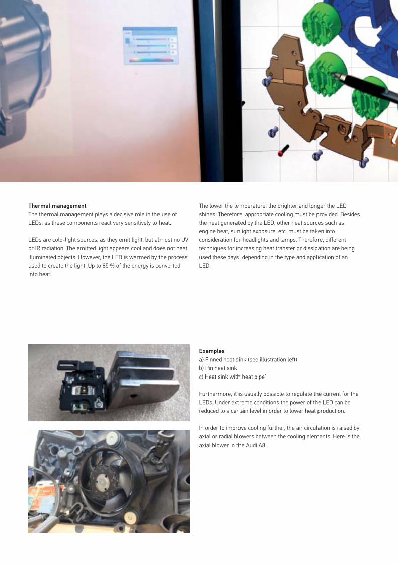
Examples
a) Finned heat sink (see illustration left)b) Pin heat sink c) Heat sink with heat pipe’
Furthermore, it is usually possible to regulate the current for the LEDs. Under extreme conditions the power of the LED can be reduced to a certain level in order to lower heat production.
In order to improve cooling further, the air circulation is raised by axial or radial blowers between the cooling elements. Here is the axial blower in the Audi A8.
Thermal management
The thermal management plays a decisive role in the use of LEDs, as these components react very sensitively to heat.
LEDs are cold-light sources, as they emit light, but almost no UV or IR radiation. The emitted light appears cool and does not heat illuminated objects. However, the LED is warmed by the process used to create the light. Up to 85 % of the energy is converted into heat.
The lower the temperature, the brighter and longer the LED shines. Therefore, appropriate cooling must be provided. Besides the heat generated by the LED, other heat sources such as engine heat, sunlight exposure, etc. must be taken into consideration for headlights and lamps. Therefore, different techniques for increasing heat transfer or dissipation are being used these days, depending in the type and application of an LED.
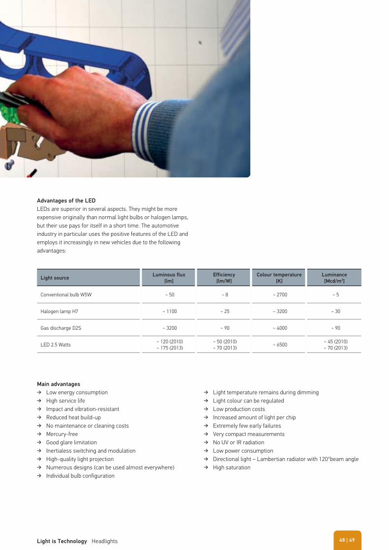
Advantages of the LED
LEDs are superior in several aspects. They might be more expensive originally than normal light bulbs or halogen lamps, but their use pays for itself in a short time. The automotive industry in particular uses the positive features of the LED and employs it increasingly in new vehicles due to the following advantages:
Main advantages
� Low energy consumption � High service life � Impact and vibration-resistant � Reduced heat build-up � No maintenance or cleaning costs � Mercury-free � Good glare limitation � Inertialess switching and modulation � High-quality light projection � Numerous designs (can be used almost everywhere) � Individual bulb configuration
Light sourceLuminous flux
[lm]
Efficiency
[lm/W]
Colour temperature
[K]
Luminance
[Mcd/m2]
Conventional bulb W5W ~ 50 ~ 8 ~ 2700 ~ 5
Halogen lamp H7 ~ 1100 ~ 25 ~ 3200 ~ 30
Gas discharge D2S ~ 3200 ~ 90 ~ 4000 ~ 90
LED 2.5 Watts ~ 120 (2010)~ 175 (2013)
~ 50 (2010)~ 70 (2013) ~ 6500 ~ 45 (2010)
~ 70 (2013)
� Light temperature remains during dimming � Light colour can be regulated � Low production costs � Increased amount of light per chip � Extremely few early failures � Very compact measurements � No UV or IR radiation � Low power consumption � Directional light – Lambertian radiator with 120°beam angle � High saturation
| 49Light is Technology Headlights 48
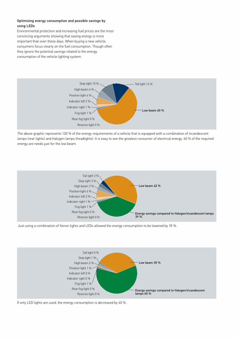
Optimising energy consumption and possible savings by
using LEDs
Environmental protection and increasing fuel prices are the most convincing arguments showing that saving energy is more important than ever these days. When buying a new vehicle, consumers focus clearly on the fuel consumption. Though often they ignore the potential savings related to the energy consumption of the vehicle lighting system.
Just using a combination of Xenon lights and LEDs allowed the energy consumption to be lowered by 39 %.
If only LED lights are used, the energy consumption is decreased by 60 %.
The above graphic represents 100 % of the energy requirements of a vehicle that is equipped with a combination of incandescent lamps (rear lights) and Halogen lamps (headlights). It is easy to see the greatest consumer of electrical energy. 60 % of the required energy are needs just for the low beam.
Low beam 42 %
Energy savings compared to Halogen/incandescent lamps 39 %
Fog light 1 %Rear fog light 0 %
Reverse light 0 %
Indicator right 1 %Indicator left 2 %Position light 6 %
High beam 3 %Stop light 3 %
Tail light 3 %
Low beam 60 %Fog light 1 %
Rear fog light 0 %
Reverse light 0 %
Indicator right 1 %
Indicator left 2 %
Position light 6 %
High beam 6 %
Stop light 10 % Tail light 14 %
Low beam 35 %
Energy savings compared to Halogen/incandescent lamps 60 %
Fog light 1 %Rear fog light 0 %
Reverse light 0 %
Indicator right 0 %Indicator left 0 %Position light 1 %
High beam 2 %Stop light 1 %
Tail light 0 %
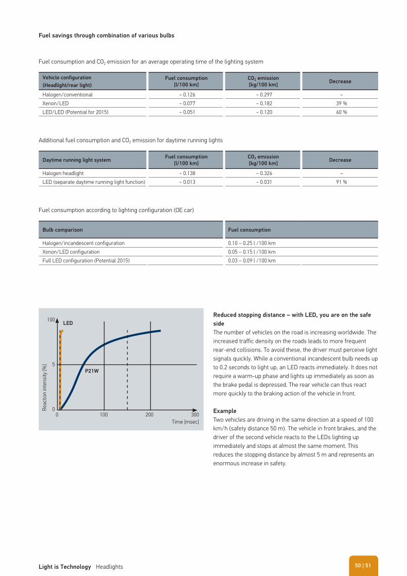
Reduced stopping distance – with LED, you are on the safe
side The number of vehicles on the road is increasing worldwide. The increased traffic density on the roads leads to more frequent rear-end collisions. To avoid these, the driver must perceive light signals quickly. While a conventional incandescent bulb needs up to 0.2 seconds to light up, an LED reacts immediately. It does not require a warm-up phase and lights up immediately as soon as the brake pedal is depressed. The rear vehicle can thus react more quickly to the braking action of the vehicle in front.
Example
Two vehicles are driving in the same direction at a speed of 100 km/h (safety distance 50 m). The vehicle in front brakes, and the driver of the second vehicle reacts to the LEDs lighting up immediately and stops at almost the same moment. This reduces the stopping distance by almost 5 m and represents an enormous increase in safety.
Fuel savings through combination of various bulbs
Vehicle configuration
(Headlight/rear light)
Fuel consumption
[l/100 km]
CO2 emission
[kg/100 km]Decrease
Halogen/conventional ~ 0.126 ~ 0.297 –Xenon/LED ~ 0.077 ~ 0.182 39 %LED/LED (Potential for 2015) ~ 0.051 ~ 0.120 60 %
Daytime running light systemFuel consumption
[l/100 km]
CO2 emission
[kg/100 km]Decrease
Halogen headlight ~ 0.138 ~ 0.326 –LED (separate daytime running light function) ~ 0.013 ~ 0.031 91 %
Bulb comparison Fuel consumption
Halogen/incandescent configuration 0.10 – 0.25 l /100 kmXenon/LED configuration 0.05 – 0.15 l /100 kmFull LED configuration (Potential 2015) 0.03 – 0.09 l /100 km
Fuel consumption and CO2 emission for an average operating time of the lighting system
Additional fuel consumption and CO2 emission for daytime running lights
Fuel consumption according to lighting configuration (OE car)
00
5
100
100
LED
P21W
200Time [msec]
Reac
tion
inte
nsity
[%]
300
| 51Light is Technology Headlights 50
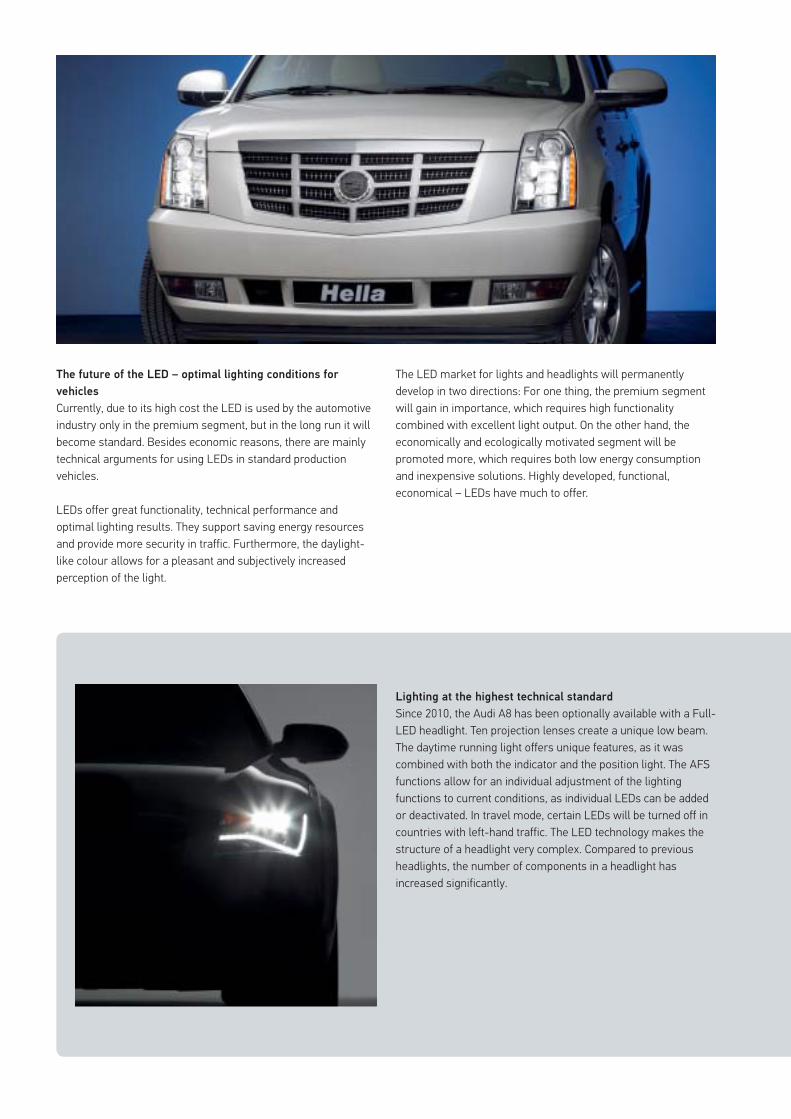
The future of the LED – optimal lighting conditions for
vehicles
Currently, due to its high cost the LED is used by the automotive industry only in the premium segment, but in the long run it will become standard. Besides economic reasons, there are mainly technical arguments for using LEDs in standard production vehicles.
LEDs offer great functionality, technical performance and optimal lighting results. They support saving energy resources and provide more security in traffic. Furthermore, the daylight-like colour allows for a pleasant and subjectively increased perception of the light.
Lighting at the highest technical standard
Since 2010, the Audi A8 has been optionally available with a Full-LED headlight. Ten projection lenses create a unique low beam. The daytime running light offers unique features, as it was combined with both the indicator and the position light. The AFS functions allow for an individual adjustment of the lighting functions to current conditions, as individual LEDs can be added or deactivated. In travel mode, certain LEDs will be turned off in countries with left-hand traffic. The LED technology makes the structure of a headlight very complex. Compared to previous headlights, the number of components in a headlight has increased significantly.
The LED market for lights and headlights will permanently develop in two directions: For one thing, the premium segment will gain in importance, which requires high functionality combined with excellent light output. On the other hand, the economically and ecologically motivated segment will be promoted more, which requires both low energy consumption and inexpensive solutions. Highly developed, functional, economical – LEDs have much to offer.
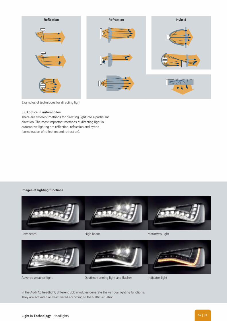
In the Audi A8 headlight, different LED modules generate the various lighting functions. They are activated or deactivated according to the traffic situation.
Low beam
Adverse weather light
High beam
Daytime running light and flasher
Motorway light
Indicator light
Images of lighting functions
Examples of techniques for directing light
Reflection Refraction Hybrid
LED optics in automobiles
There are different methods for directing light into a particular direction. The most important methods of directing light in automotive lighting are reflection, refraction and hybrid (combination of reflection and refraction).
| 53Light is Technology Headlights 52
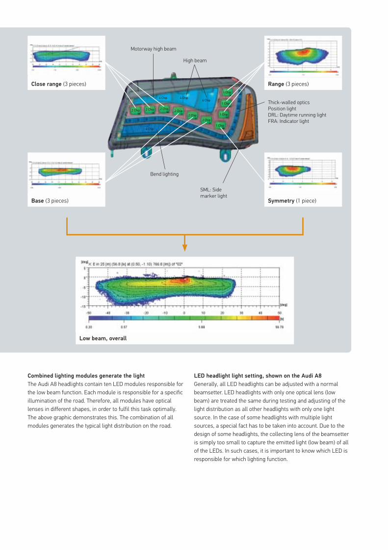
4 Chip
4 Chip
4 Chip4 Chip
1 Chip
1 Chip
1 Chip
1 Chip
2 Chip2 Chip
2 Chip2 Chip2 Chip2 Chip
Combined lighting modules generate the light
The Audi A8 headlights contain ten LED modules responsible for the low beam function. Each module is responsible for a specific illumination of the road. Therefore, all modules have optical lenses in different shapes, in order to fulfil this task optimally. The above graphic demonstrates this. The combination of all modules generates the typical light distribution on the road.
LED headlight light setting, shown on the Audi A8
Generally, all LED headlights can be adjusted with a normal beamsetter. LED headlights with only one optical lens (low beam) are treated the same during testing and adjusting of the light distribution as all other headlights with only one light source. In the case of some headlights with multiple light sources, a special fact has to be taken into account. Due to the design of some headlights, the collecting lens of the beamsetter is simply too small to capture the emitted light (low beam) of all of the LEDs. In such cases, it is important to know which LED is responsible for which lighting function.
Range (3 pieces)
High beam
Bend lighting
Motorway high beam
Thick-walled opticsPosition lightDRL: Daytime running lightFRA: Indicator light
SML: Side marker light
Symmetry (1 piece)
Close range (3 pieces)
Base (3 pieces)
Low beam, overall
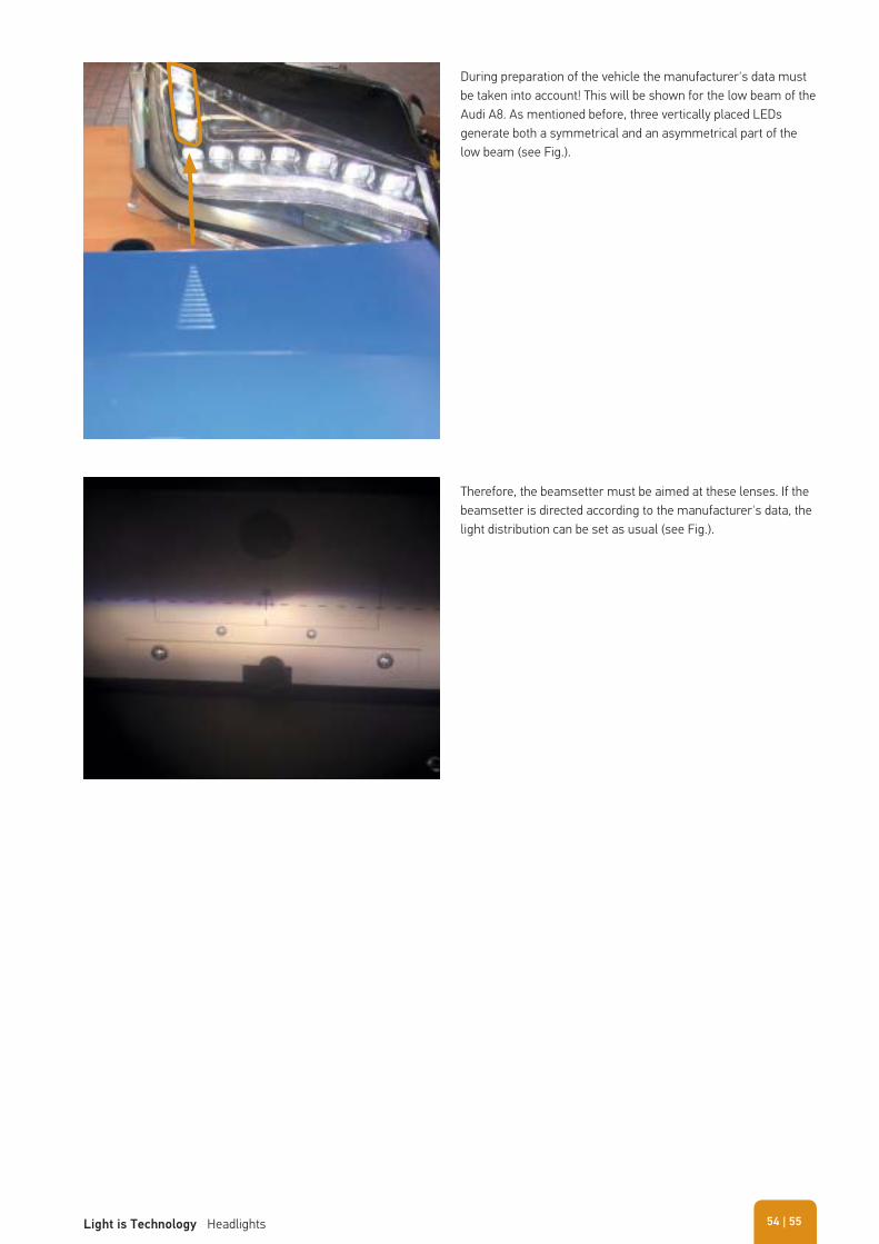
During preparation of the vehicle the manufacturer's data must be taken into account! This will be shown for the low beam of the Audi A8. As mentioned before, three vertically placed LEDs generate both a symmetrical and an asymmetrical part of the low beam (see Fig.).
Therefore, the beamsetter must be aimed at these lenses. If the beamsetter is directed according to the manufacturer's data, the light distribution can be set as usual (see Fig.).
| 55Light is Technology Headlights 54
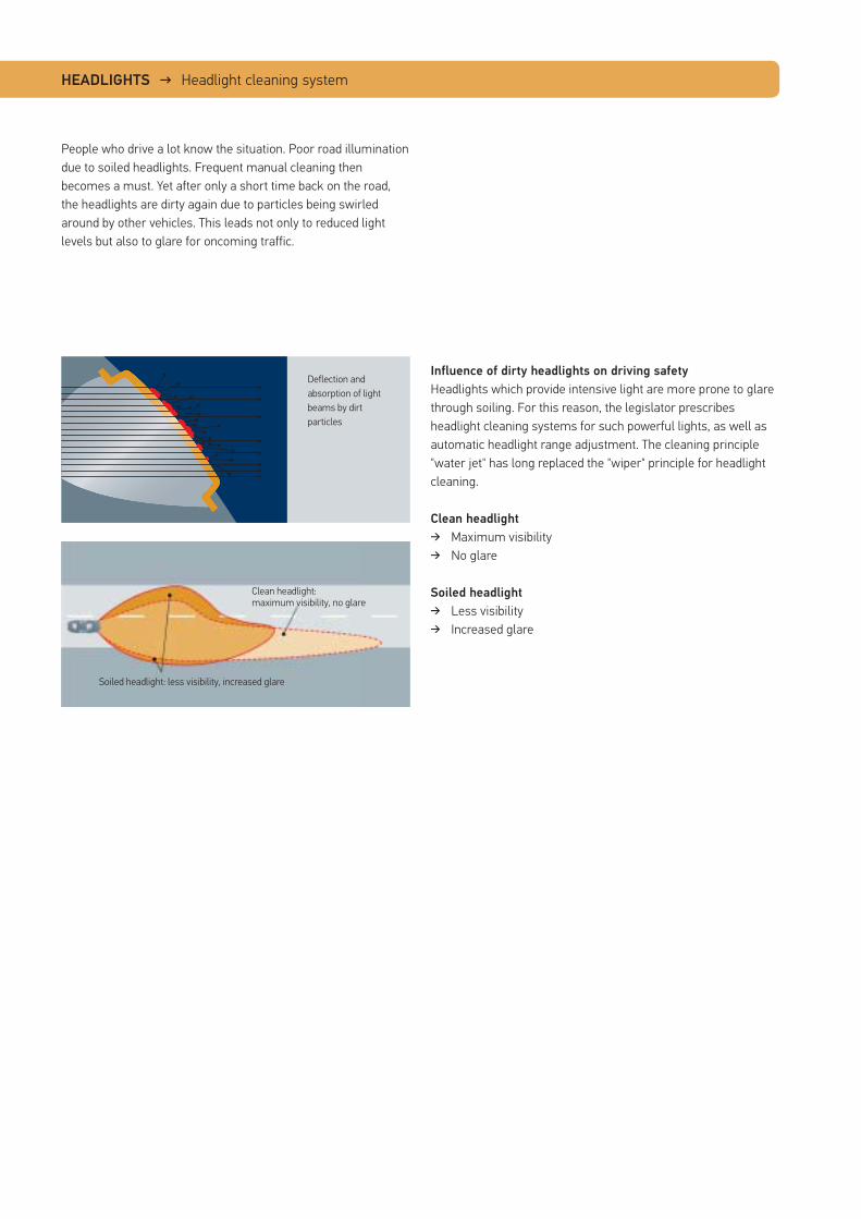
HEADLIGHTS → Headlight cleaning system
People who drive a lot know the situation. Poor road illumination due to soiled headlights. Frequent manual cleaning then becomes a must. Yet after only a short time back on the road, the headlights are dirty again due to particles being swirled around by other vehicles. This leads not only to reduced light levels but also to glare for oncoming traffic.
Influence of dirty headlights on driving safety
Headlights which provide intensive light are more prone to glare through soiling. For this reason, the legislator prescribes headlight cleaning systems for such powerful lights, as well as automatic headlight range adjustment. The cleaning principle "water jet" has long replaced the "wiper" principle for headlight cleaning.
Clean headlight � Maximum visibility � No glare
Soiled headlight � Less visibility � Increased glare
Clean headlight: maximum visibility, no glare
Soiled headlight: less visibility, increased glare
Deflection and absorption of light beams by dirt particles
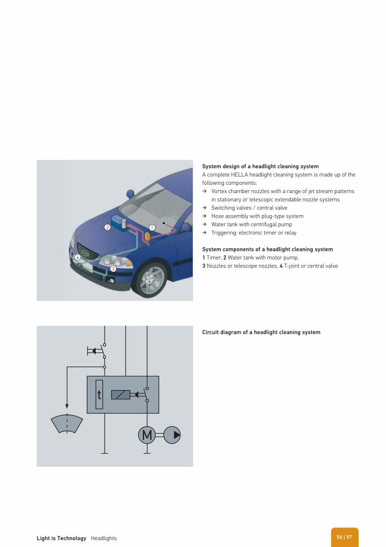
System design of a headlight cleaning system
A complete HELLA headlight cleaning system is made up of the following components:
� Vortex chamber nozzles with a range of jet stream patterns in stationary or telescopic extendable nozzle systems
� Switching valves / central valve � Hose assembly with plug-type system � Water tank with centrifugal pump � Triggering: electronic timer or relay
System components of a headlight cleaning system 1 Timer, 2 Water tank with motor pump,3 Nozzles or telescope nozzles, 4 T-joint or central valve
Circuit diagram of a headlight cleaning system
12
3
4
t
M
| 57Light is Technology Headlights 56
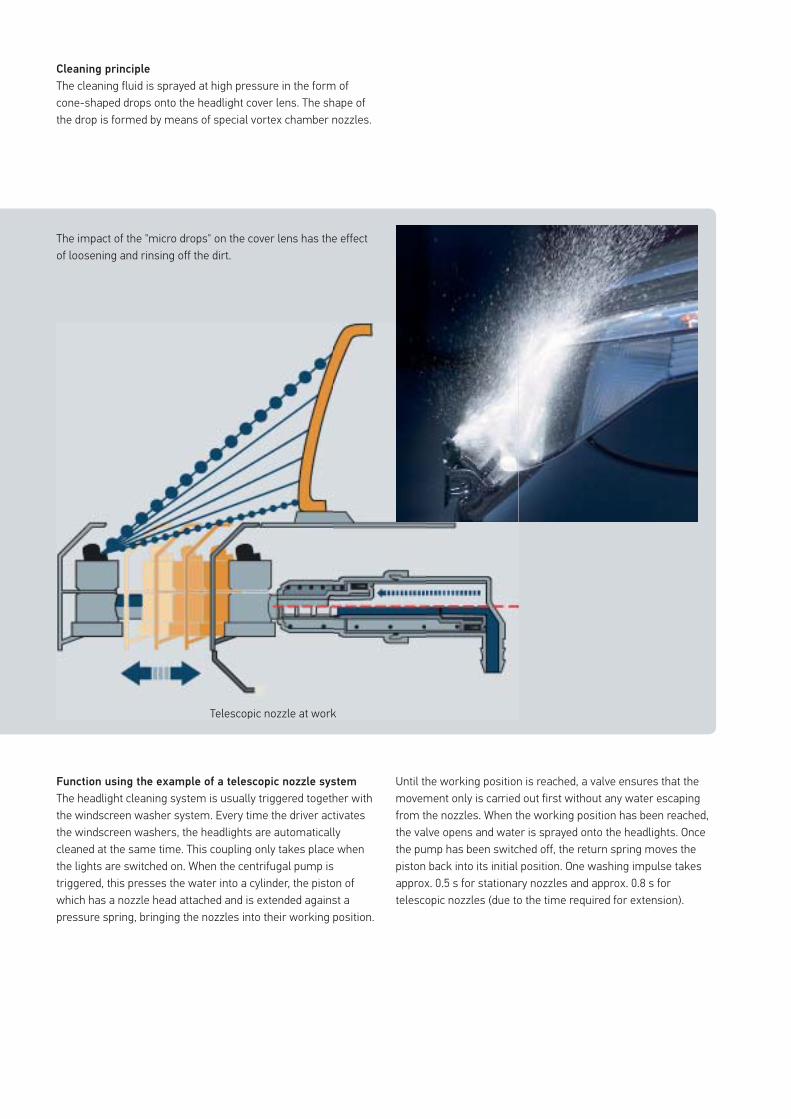
Cleaning principle
The cleaning fluid is sprayed at high pressure in the form of cone-shaped drops onto the headlight cover lens. The shape of the drop is formed by means of special vortex chamber nozzles.
Function using the example of a telescopic nozzle system
The headlight cleaning system is usually triggered together with the windscreen washer system. Every time the driver activates the windscreen washers, the headlights are automatically cleaned at the same time. This coupling only takes place when the lights are switched on. When the centrifugal pump is triggered, this presses the water into a cylinder, the piston of which has a nozzle head attached and is extended against a pressure spring, bringing the nozzles into their working position.
The impact of the "micro drops" on the cover lens has the effect of loosening and rinsing off the dirt.
Telescopic nozzle at work
Until the working position is reached, a valve ensures that the movement only is carried out first without any water escaping from the nozzles. When the working position has been reached, the valve opens and water is sprayed onto the headlights. Once the pump has been switched off, the return spring moves the piston back into its initial position. One washing impulse takes approx. 0.5 s for stationary nozzles and approx. 0.8 s for telescopic nozzles (due to the time required for extension).
Telescopic nozzle at work
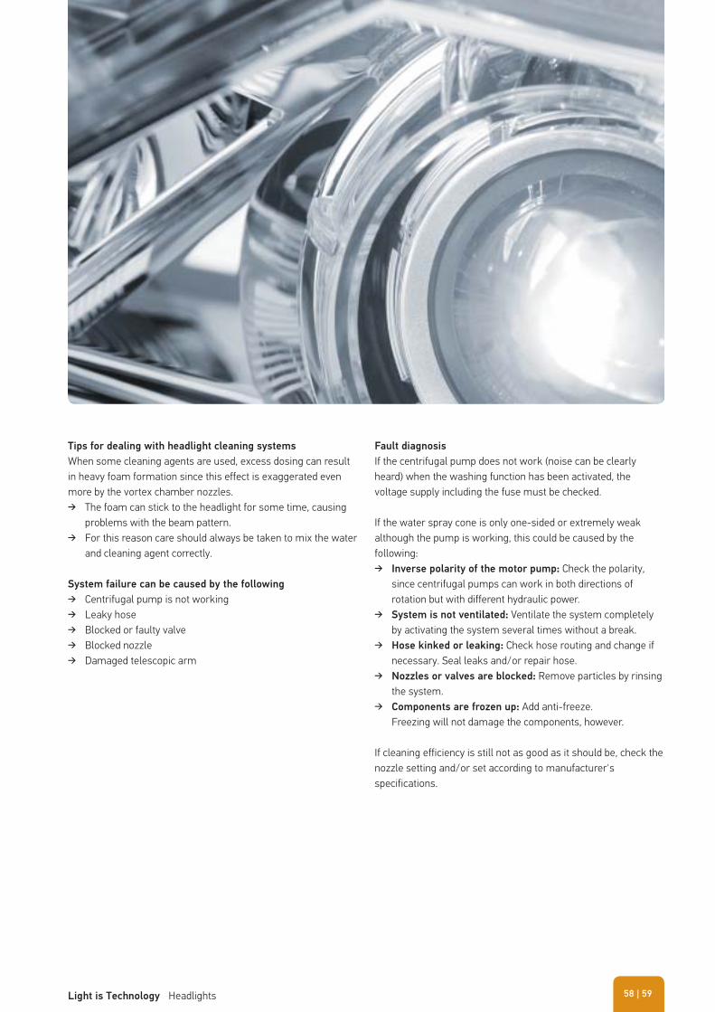
Tips for dealing with headlight cleaning systems
When some cleaning agents are used, excess dosing can result in heavy foam formation since this effect is exaggerated even more by the vortex chamber nozzles.
� The foam can stick to the headlight for some time, causing problems with the beam pattern.
� For this reason care should always be taken to mix the water and cleaning agent correctly.
System failure can be caused by the following
� Centrifugal pump is not working � Leaky hose � Blocked or faulty valve � Blocked nozzle � Damaged telescopic arm
Fault diagnosis
If the centrifugal pump does not work (noise can be clearly heard) when the washing function has been activated, the voltage supply including the fuse must be checked.
If the water spray cone is only one-sided or extremely weak although the pump is working, this could be caused by the following:
� Inverse polarity of the motor pump: Check the polarity, since centrifugal pumps can work in both directions of rotation but with different hydraulic power.
� System is not ventilated: Ventilate the system completely by activating the system several times without a break.
� Hose kinked or leaking: Check hose routing and change if necessary. Seal leaks and/or repair hose.
� Nozzles or valves are blocked: Remove particles by rinsing the system.
� Components are frozen up: Add anti-freeze. Freezing will not damage the components, however.
If cleaning efficiency is still not as good as it should be, check the nozzle setting and/or set according to manufacturer's specifications.
| 59Light is Technology Headlights 58
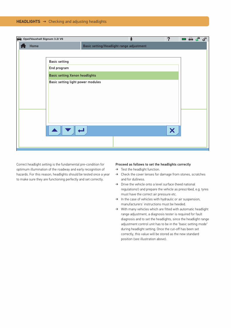
HEADLIGHTS → Checking and adjusting headlights
Proceed as follows to set the headlights correctly
� Test the headlight function. � Check the cover lenses for damage from stones, scratches
and for dullness. � Drive the vehicle onto a level surface (heed national
regulations!) and prepare the vehicle as prescribed, e.g. tyres must have the correct air pressure etc.
� In the case of vehicles with hydraulic or air suspension, manufacturers' instructions must be heeded.
� With many vehicles which are fitted with automatic headlight range adjustment, a diagnosis tester is required for fault diagnosis and to set the headlights, since the headlight range adjustment control unit has to be in the "basic setting mode" during headlight setting. Once the cut-off has been set correctly, this value will be stored as the new standard position (see illustration above).
Correct headlight setting is the fundamental pre-condition for optimum illumination of the roadway and early recognition of hazards. For this reason, headlights should be tested once a year to make sure they are functioning perfectly and set correctly.
Opel/Vauxhall Signum 3.2i V6
Home Basic setting/Headlight range adjustment
Basic setting
End program
Basic setting Xenon headlights
Basic setting light power modules
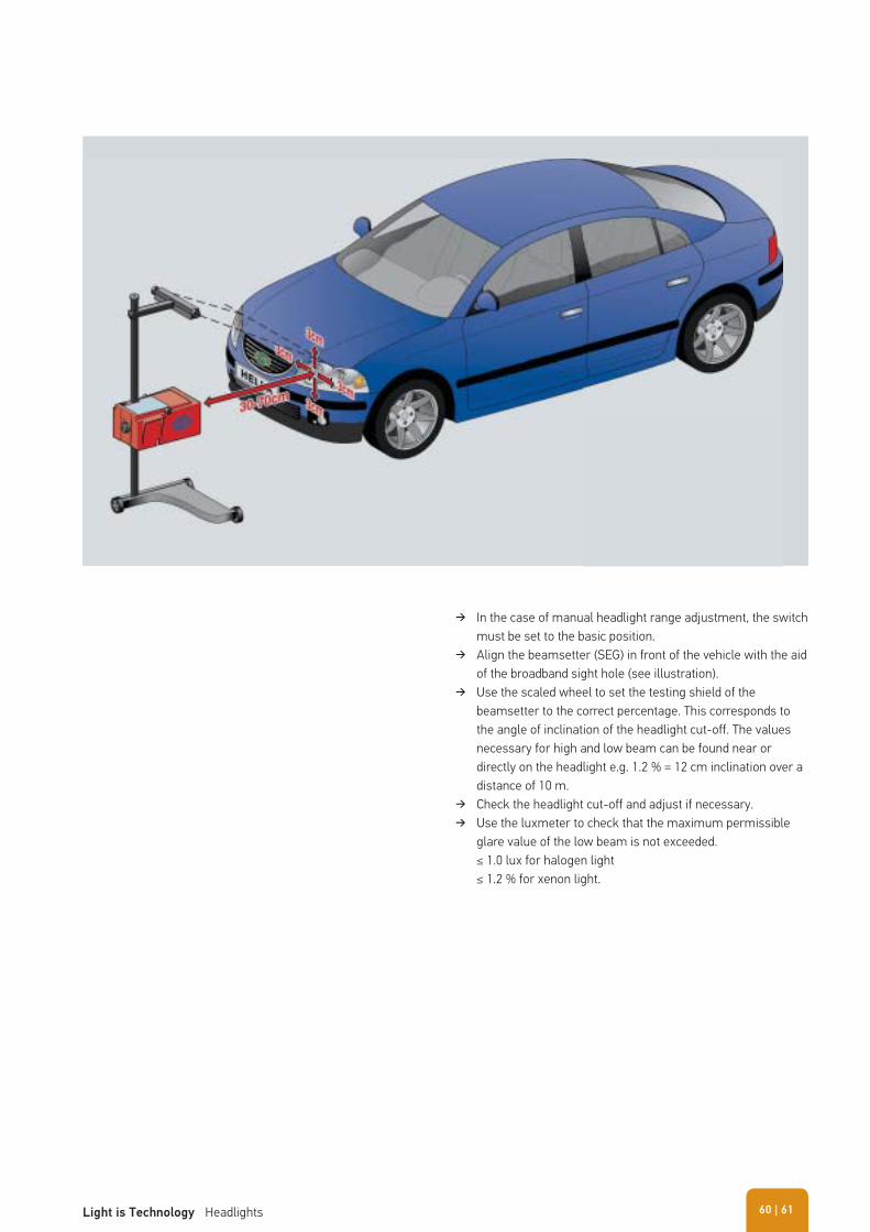
� In the case of manual headlight range adjustment, the switch must be set to the basic position.
� Align the beamsetter (SEG) in front of the vehicle with the aid of the broadband sight hole (see illustration).
� Use the scaled wheel to set the testing shield of the beamsetter to the correct percentage. This corresponds to the angle of inclination of the headlight cut-off. The values necessary for high and low beam can be found near or directly on the headlight e.g. 1.2 % = 12 cm inclination over a distance of 10 m.
� Check the headlight cut-off and adjust if necessary. � Use the luxmeter to check that the maximum permissible
glare value of the low beam is not exceeded.≤ 1.0 lux for halogen light≤ 1.2 % for xenon light.
| 61Light is Technology Headlights 60
� Structure of a car signal light 63 � Tips for dealing with signal lights 64 � ASIGNIS® – Adaptive Signal System 65
SIGNAL LIGHTS
Exterior lights – whether attached at the front, side or rear of the vehicle - provide information for other road users through their signals and are thus responsible for safety on the roads to a substantial extent.
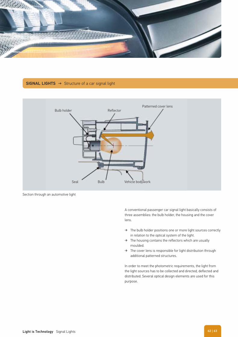
SIGNAL LIGHTS → Structure of a car signal light
A conventional passenger car signal light basically consists of three assemblies: the bulb holder, the housing and the cover lens.
� The bulb holder positions one or more light sources correctly in relation to the optical system of the light.
� The housing contains the reflectors which are usually moulded.
� The cover lens is responsible for light distribution through additional patterned structures.
In order to meet the photometric requirements, the light from the light sources has to be collected and directed, deflected and distributed. Several optical design elements are used for this purpose.
Section through an automotive light
Bulb holder Reflector
Seal Bulb Vehicle bodywork
Patterned cover lens
| 63Light is Technology Signal Lights 62
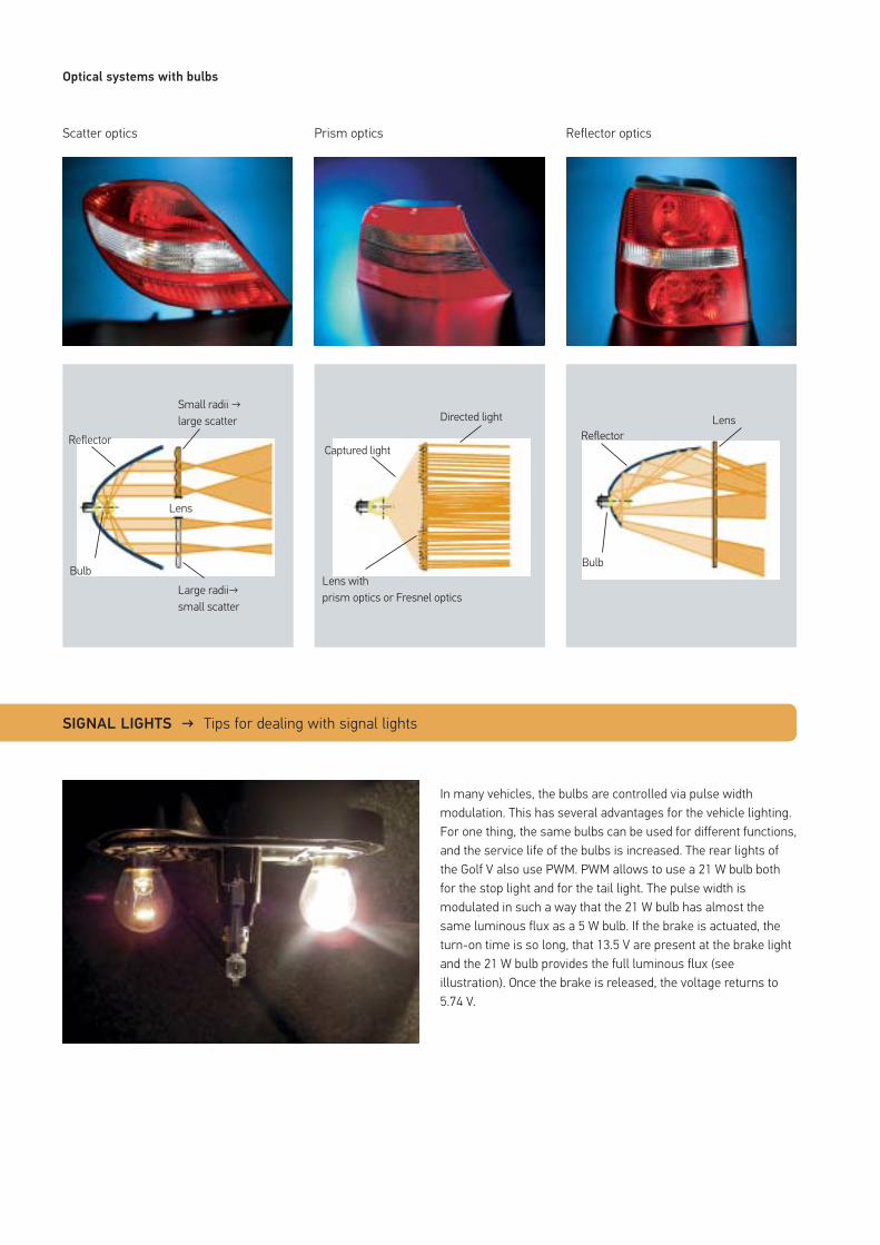
Optical systems with bulbs
Scatter optics
In many vehicles, the bulbs are controlled via pulse width modulation. This has several advantages for the vehicle lighting. For one thing, the same bulbs can be used for different functions, and the service life of the bulbs is increased. The rear lights of the Golf V also use PWM. PWM allows to use a 21 W bulb both for the stop light and for the tail light. The pulse width is modulated in such a way that the 21 W bulb has almost the same luminous flux as a 5 W bulb. If the brake is actuated, the turn-on time is so long, that 13.5 V are present at the brake light and the 21 W bulb provides the full luminous flux (see illustration). Once the brake is released, the voltage returns to 5.74 V.
Prism optics Reflector optics
Lens
Bulb
Reflector
Small radii → large scatter
Large radii→ small scatter
Reflector
Lens
Bulb
Directed light
Lens withprism optics or Fresnel optics
Captured light
SIGNAL LIGHTS → Tips for dealing with signal lights
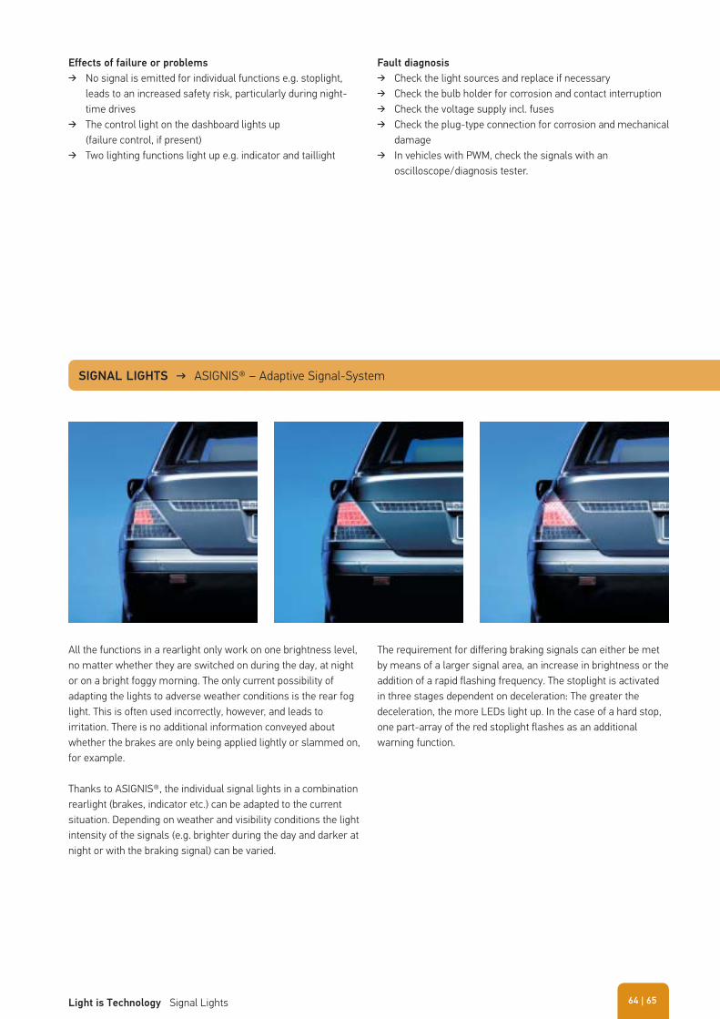
Effects of failure or problems
� No signal is emitted for individual functions e.g. stoplight, leads to an increased safety risk, particularly during night-time drives
� The control light on the dashboard lights up (failure control, if present)
� Two lighting functions light up e.g. indicator and taillight
Fault diagnosis
� Check the light sources and replace if necessary � Check the bulb holder for corrosion and contact interruption � Check the voltage supply incl. fuses � Check the plug-type connection for corrosion and mechanical
damage � In vehicles with PWM, check the signals with an
oscilloscope/diagnosis tester.
All the functions in a rearlight only work on one brightness level, no matter whether they are switched on during the day, at night or on a bright foggy morning. The only current possibility of adapting the lights to adverse weather conditions is the rear fog light. This is often used incorrectly, however, and leads to irritation. There is no additional information conveyed about whether the brakes are only being applied lightly or slammed on, for example.
Thanks to ASIGNIS®, the individual signal lights in a combination rearlight (brakes, indicator etc.) can be adapted to the current situation. Depending on weather and visibility conditions the light intensity of the signals (e.g. brighter during the day and darker at night or with the braking signal) can be varied.
SIGNAL LIGHTS → ASIGNIS® – Adaptive Signal-System
The requirement for differing braking signals can either be met by means of a larger signal area, an increase in brightness or the addition of a rapid flashing frequency. The stoplight is activated in three stages dependent on deceleration: The greater the deceleration, the more LEDs light up. In the case of a hard stop, one part-array of the red stoplight flashes as an additional warning function.
| 65Light is Technology Signal Lights 64
� Driver assistance system 67
INTELLIGENT LIGHTING SYSTEMS
One of the first lighting-based driver assistance systems was dynamic bend lighting, which was introduced in 2003. In this system, the light modules are moved depending on the steering angle. This almost doubles the visible area in curves.
A further development of the dynamic bend lighting is the Advanced Frontlighting System (AFS). This uses not only the steering angle, but also the speed as a parameter for lighting the road. On the basis of these internal vehicle data, the cylinder of the VarioX® module can generate different light distributions, e.g. for city streets or country roads, adverse weather or motorways.
A further step is the development of the adaptive cut-off (aHDG). This uses data from the surroundings of the vehicle to generate the light distribution. A camera detects oncoming or preceding vehicles, and with the aid of a stepper motor, the cylinder of the
VarioX® module can be turned to the required position within a few milliseconds. Therefore, the light beam always ends directly in front of the oncoming or preceding vehicles.
When using a glare-free high beam, the driver constantly drives with the high beam on. When the camera detects other road users, they are excluded from the high beam distribution pattern.
LEDs offer the opposite option. As they can be addressed individually, specific objects, such as children playing by the side of the road, can be illuminated. This draws the driver's attention to these potential hazards in time, in order to allow for an early reaction.
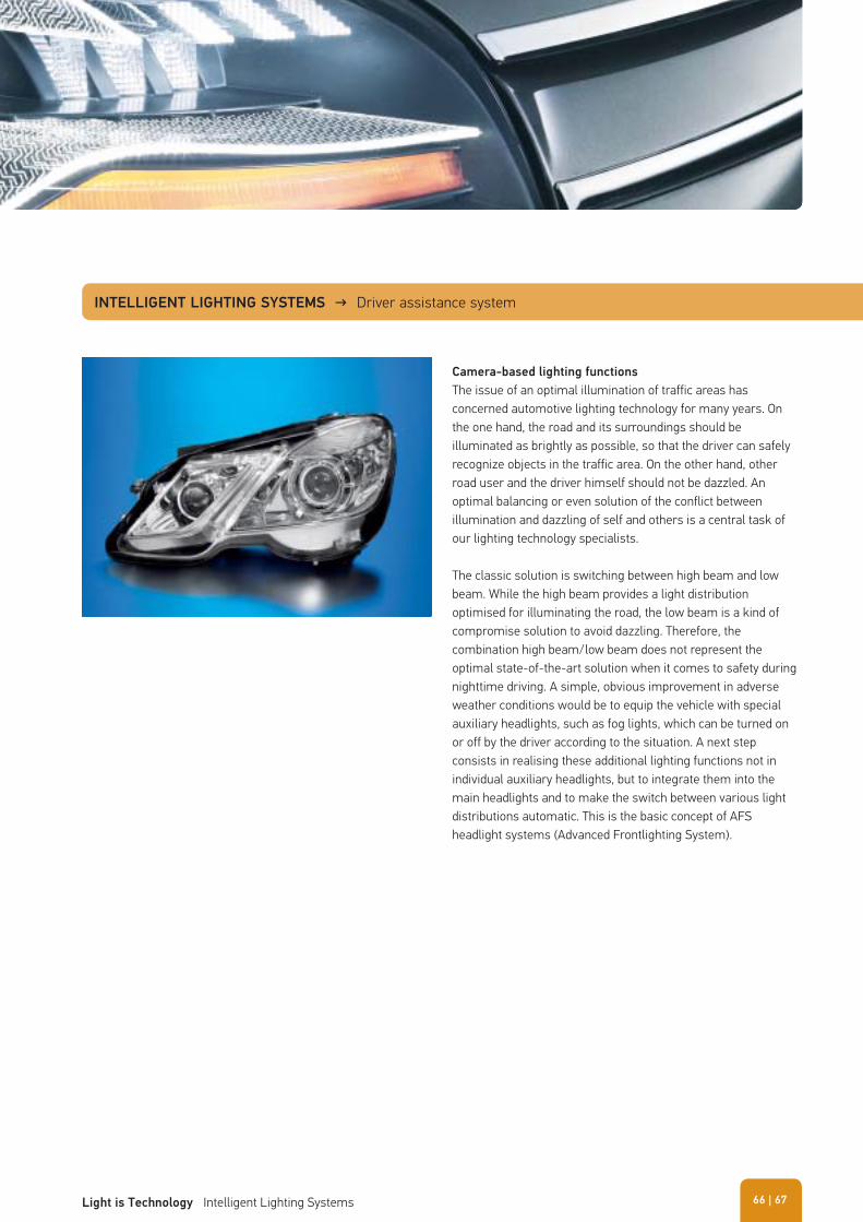
INTELLIGENT LIGHTING SYSTEMS → Driver assistance system
Camera-based lighting functions
The issue of an optimal illumination of traffic areas has concerned automotive lighting technology for many years. On the one hand, the road and its surroundings should be illuminated as brightly as possible, so that the driver can safely recognize objects in the traffic area. On the other hand, other road user and the driver himself should not be dazzled. An optimal balancing or even solution of the conflict between illumination and dazzling of self and others is a central task of our lighting technology specialists.
The classic solution is switching between high beam and low beam. While the high beam provides a light distribution optimised for illuminating the road, the low beam is a kind of compromise solution to avoid dazzling. Therefore, the combination high beam/low beam does not represent the optimal state-of-the-art solution when it comes to safety during nighttime driving. A simple, obvious improvement in adverse weather conditions would be to equip the vehicle with special auxiliary headlights, such as fog lights, which can be turned on or off by the driver according to the situation. A next step consists in realising these additional lighting functions not in individual auxiliary headlights, but to integrate them into the main headlights and to make the switch between various light distributions automatic. This is the basic concept of AFS headlight systems (Advanced Frontlighting System).
| 67Light is Technology Intelligent Lighting Systems 66
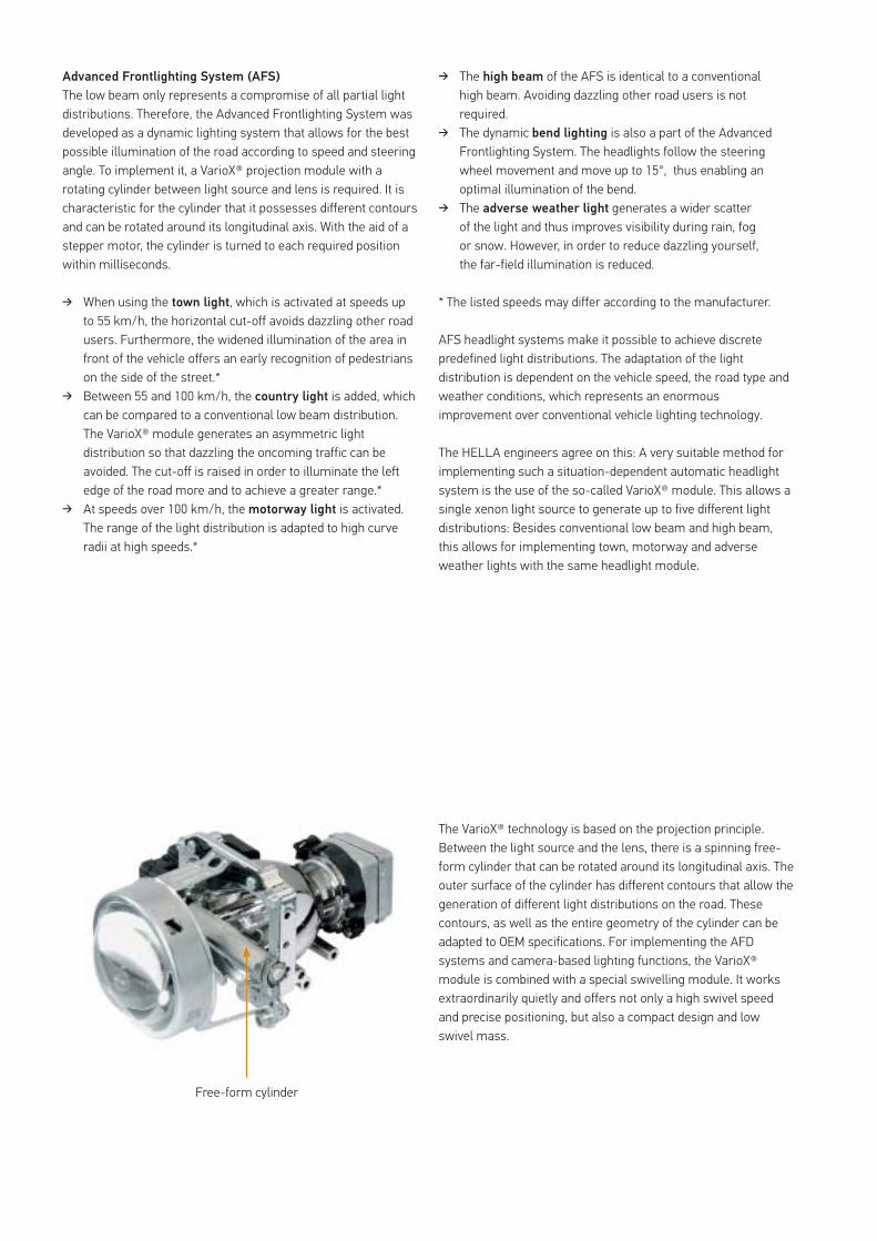
Advanced Frontlighting System (AFS)
The low beam only represents a compromise of all partial light distributions. Therefore, the Advanced Frontlighting System was developed as a dynamic lighting system that allows for the best possible illumination of the road according to speed and steering angle. To implement it, a VarioX® projection module with a rotating cylinder between light source and lens is required. It is characteristic for the cylinder that it possesses different contours and can be rotated around its longitudinal axis. With the aid of a stepper motor, the cylinder is turned to each required position within milliseconds.
� When using the town light, which is activated at speeds up to 55 km/h, the horizontal cut-off avoids dazzling other road users. Furthermore, the widened illumination of the area in front of the vehicle offers an early recognition of pedestrians on the side of the street.*
� Between 55 and 100 km/h, the country light is added, which can be compared to a conventional low beam distribution. The VarioX® module generates an asymmetric light distribution so that dazzling the oncoming traffic can be avoided. The cut-off is raised in order to illuminate the left edge of the road more and to achieve a greater range.*
� At speeds over 100 km/h, the motorway light is activated. The range of the light distribution is adapted to high curve radii at high speeds.*
� The high beam of the AFS is identical to a conventional high beam. Avoiding dazzling other road users is not required.
� The dynamic bend lighting is also a part of the Advanced Frontlighting System. The headlights follow the steering wheel movement and move up to 15°, thus enabling an optimal illumination of the bend.
� The adverse weather light generates a wider scatter of the light and thus improves visibility during rain, fog or snow. However, in order to reduce dazzling yourself, the far-field illumination is reduced.
* The listed speeds may differ according to the manufacturer.
AFS headlight systems make it possible to achieve discrete predefined light distributions. The adaptation of the light distribution is dependent on the vehicle speed, the road type and weather conditions, which represents an enormous improvement over conventional vehicle lighting technology.
The HELLA engineers agree on this: A very suitable method for implementing such a situation-dependent automatic headlight system is the use of the so-called VarioX® module. This allows a single xenon light source to generate up to five different light distributions: Besides conventional low beam and high beam, this allows for implementing town, motorway and adverse weather lights with the same headlight module.
The VarioX® technology is based on the projection principle. Between the light source and the lens, there is a spinning free-form cylinder that can be rotated around its longitudinal axis. The outer surface of the cylinder has different contours that allow the generation of different light distributions on the road. These contours, as well as the entire geometry of the cylinder can be adapted to OEM specifications. For implementing the AFD systems and camera-based lighting functions, the VarioX® module is combined with a special swivelling module. It works extraordinarily quietly and offers not only a high swivel speed and precise positioning, but also a compact design and low swivel mass.
Free-form cylinder
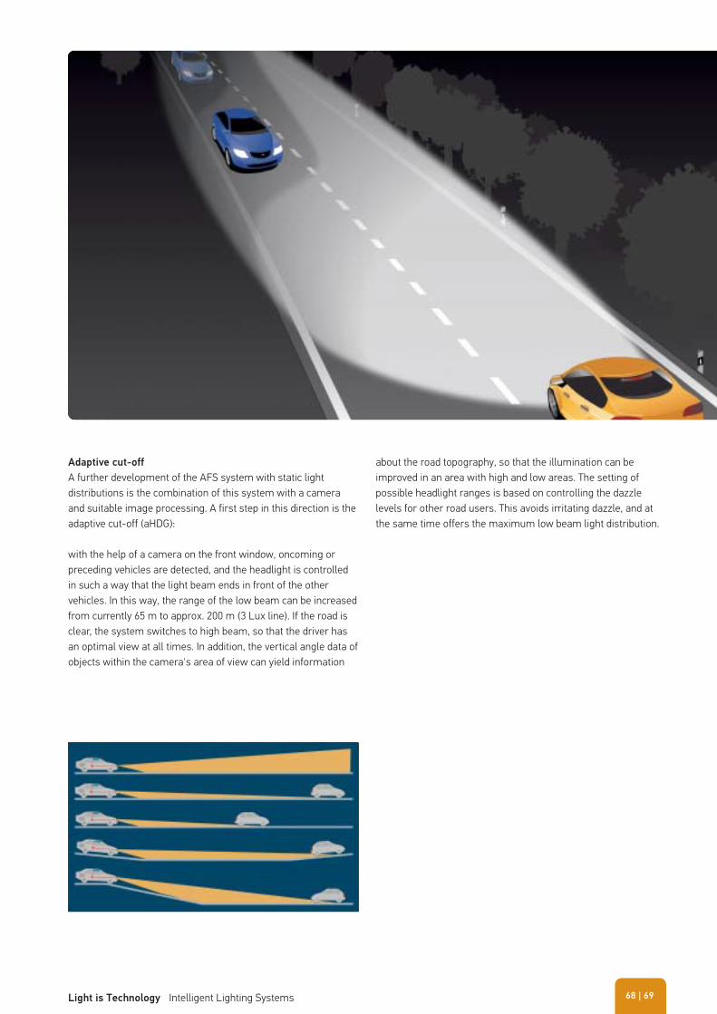
Adaptive cut-off
A further development of the AFS system with static light distributions is the combination of this system with a camera and suitable image processing. A first step in this direction is the adaptive cut-off (aHDG):
with the help of a camera on the front window, oncoming or preceding vehicles are detected, and the headlight is controlled in such a way that the light beam ends in front of the other vehicles. In this way, the range of the low beam can be increased from currently 65 m to approx. 200 m (3 Lux line). If the road is clear, the system switches to high beam, so that the driver has an optimal view at all times. In addition, the vertical angle data of objects within the camera's area of view can yield information
about the road topography, so that the illumination can be improved in an area with high and low areas. The setting of possible headlight ranges is based on controlling the dazzle levels for other road users. This avoids irritating dazzle, and at the same time offers the maximum low beam light distribution.
| 69Light is Technology Intelligent Lighting Systems 68
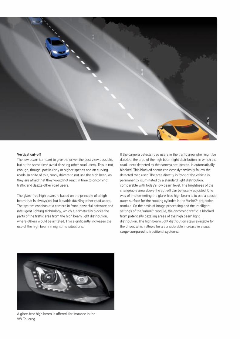
Vertical cut-off
The low beam is meant to give the driver the best view possible, but at the same time avoid dazzling other road users. This is not enough, though, particularly at higher speeds and on curving roads. In spite of this, many drivers to not use the high bean, as they are afraid that they would not react in time to oncoming traffic and dazzle other road users.
The glare-free high beam, is based on the principle of a high beam that is always on, but it avoids dazzling other road users. The system consists of a camera in front, powerful software and intelligent lighting technology, which automatically blocks the parts of the traffic area from the high beam light distribution, where others would be irritated. This significantly increases the use of the high beam in nighttime situations.
A glare-free high beam is offered, for instance in the VW Touareg.
If the camera detects road users in the traffic area who might be dazzled, the area of the high beam light distribution, in which the road users detected by the camera are located, is automatically blocked. This blocked sector can even dynamically follow the detected road user. The area directly in front of the vehicle is permanently illuminated by a standard light distribution, comparable with today's low beam level. The brightness of the changeable area above the cut-off can be locally adjusted. One way of implementing the glare-free high beam is to use a special outer surface for the rotating cylinder in the VarioX® projection module. On the basis of image processing and the intelligent settings of the VarioX® module, the oncoming traffic is blocked from potentially dazzling areas of the high beam light distribution. The high beam light distribution stays available for the driver, which allows for a considerable increase in visual range compared to traditional systems.
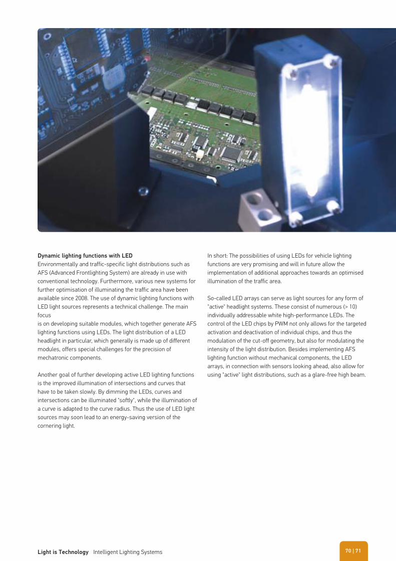
Dynamic lighting functions with LED
Environmentally and traffic-specific light distributions such as AFS (Advanced Frontlighting System) are already in use with conventional technology. Furthermore, various new systems for further optimisation of illuminating the traffic area have been available since 2008. The use of dynamic lighting functions with LED light sources represents a technical challenge. The main focus is on developing suitable modules, which together generate AFS lighting functions using LEDs. The light distribution of a LED headlight in particular, which generally is made up of different modules, offers special challenges for the precision of mechatronic components.
Another goal of further developing active LED lighting functions is the improved illumination of intersections and curves that have to be taken slowly. By dimming the LEDs, curves and intersections can be illuminated "softly", while the illumination of a curve is adapted to the curve radius. Thus the use of LED light sources may soon lead to an energy-saving version of the cornering light.
In short: The possibilities of using LEDs for vehicle lighting functions are very promising and will in future allow the implementation of additional approaches towards an optimised illumination of the traffic area.
So-called LED arrays can serve as light sources for any form of "active" headlight systems. These consist of numerous (> 10) individually addressable white high-performance LEDs. The control of the LED chips by PWM not only allows for the targeted activation and deactivation of individual chips, and thus the modulation of the cut-off geometry, but also for modulating the intensity of the light distribution. Besides implementing AFS lighting function without mechanical components, the LED arrays, in connection with sensors looking ahead, also allow for using "active" light distributions, such as a glare-free high beam.
| 71Light is Technology Intelligent Lighting Systems 70
� Headlights (Car and CV) 73 � Headlight range adjustment 77 � Headlight cleaning system 78 � Signal lights 78
STATUTORY REGULATIONS
The statutory provisions need to be taken into account if a vehicle is to be correctly equipped or retrofitted with parts. On the following pages, we would like to present the statutory regulations.
Detailed information about statutory regulations in accordance to ECE regulation 48 for the assembly of front, side and rear lights can be found in the HELLA brochure "Statutory Regulations For Cars And Trailers Pursuant To ECE Ruling 48".
Experience has shown that statutory regulations frequently change. Therefore we can assume no liability for these equipment regulations.
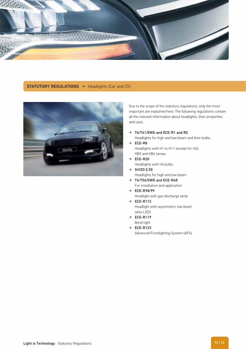
STATUTORY REGULATIONS → Headlights (Car and CV)
Due to the scope of the statutory regulations, only the most important are explained here. The following regulations contain all the relevant information about headlights, their properties and uses.
� 76/761/EWG and ECE-R1 and R2
Headlights for high and low beam and their bulbs � ECE-R8
Headlights with H1 to H11 (except for H4), HB3 and HB4 lamps
� ECE-R20
Headlights with H4 bulbs � StVZO § 50
Headlights for high and low beam � 76/756/EWG and ECE-R48
For installation and application � ECE-R98/99
Headlight with gas discharge lamp � ECE-R112
Headlight with asymmetric low beam (also LED)
� ECE-R119
Bend light � ECE-R123
Advanced Frontlighting System (AFS)
| 73Light is Technology Statutory Regulations 72
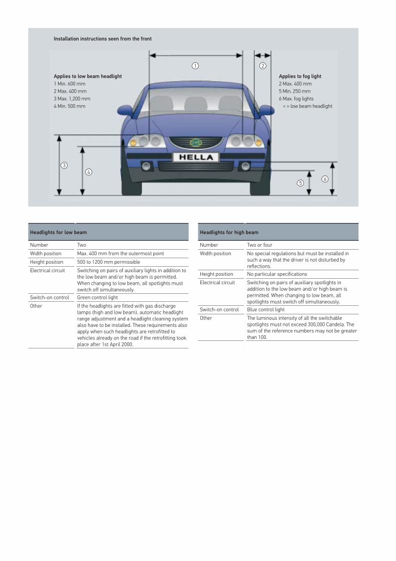
Installation instructions seen from the front
Applies to low beam headlight
1 Min. 600 mm2 Max. 400 mm3 Max. 1,200 mm4 Min. 500 mm
Applies to fog light
2 Max. 400 mm5 Min. 250 mm6 Max. fog lights < = low beam headlight
1
3
5
46
2
Headlights for low beam
Number TwoWidth position Max. 400 mm from the outermost pointHeight position 500 to 1200 mm permissibleElectrical circuit Switching on pairs of auxiliary lights in addition to
the low beam and/or high beam is permitted. When changing to low beam, all spotlights must switch off simultaneously.
Switch-on control Green control lightOther If the headlights are fitted with gas discharge
lamps (high and low beam), automatic headlight range adjustment and a headlight cleaning system also have to be installed. These requirements also apply when such headlights are retrofitted to vehicles already on the road if the retrofitting took place after 1st April 2000.
Headlights for high beam
Number Two or fourWidth position No special regulations but must be installed in
such a way that the driver is not disturbed by reflections.
Height position No particular specificationsElectrical circuit Switching on pairs of auxiliary spotlights in
addition to the low beam and/or high beam is permitted. When changing to low beam, all spotlights must switch off simultaneously.
Switch-on control Blue control lightOther The luminous intensity of all the switchable
spotlights must not exceed 300,000 Candela. The sum of the reference numbers may not be greater than 100.
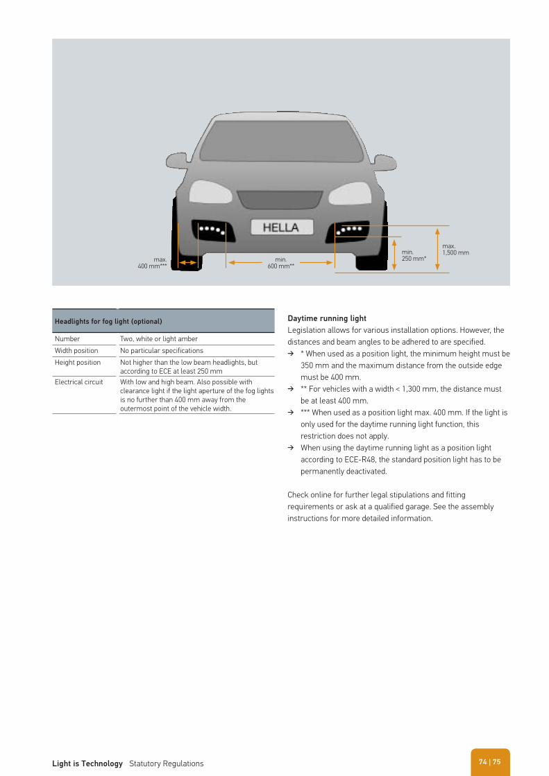
max.1,500 mmmin.
250 mm*min.600 mm**
max.400 mm***
Headlights for fog light (optional)
Number Two, white or light amberWidth position No particular specificationsHeight position Not higher than the low beam headlights, but
according to ECE at least 250 mmElectrical circuit With low and high beam. Also possible with
clearance light if the light aperture of the fog lights is no further than 400 mm away from the outermost point of the vehicle width.
Daytime running light
Legislation allows for various installation options. However, the distances and beam angles to be adhered to are specified.
� * When used as a position light, the minimum height must be 350 mm and the maximum distance from the outside edge must be 400 mm.
� ** For vehicles with a width < 1,300 mm, the distance must be at least 400 mm.
� *** When used as a position light max. 400 mm. If the light is only used for the daytime running light function, this restriction does not apply.
� When using the daytime running light as a position light according to ECE-R48, the standard position light has to be permanently deactivated.
Check online for further legal stipulations and fitting requirements or ask at a qualified garage. See the assembly instructions for more detailed information.
| 75Light is Technology Statutory Regulations 74
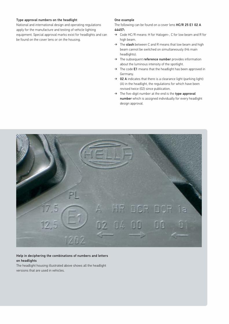
Type approval numbers on the headlight
National and international design and operating regulations apply for the manufacture and testing of vehicle lighting equipment. Special approval marks exist for headlights and can be found on the cover lens or on the housing.
Help in deciphering the combinations of numbers and letters
on headlights
The headlight housing illustrated above shows all the headlight versions that are used in vehicles.
One example
The following can be found on a cover lens HC/R 25 E1 02 A
44457:
� Code HC/R means: H for Halogen-, C for low beam and R for high beam.
� The slash between C and R means that low beam and high beam cannot be switched on simultaneously (H4 main headlights).
� The subsequent reference number provides information about the luminous intensity of the spotlight.
� The code E1 means that the headlight has been approved in Germany.
� 02 A indicates that there is a clearance light (parking light) (A) in the headlight, the regulations for which have been revised twice (02) since publication.
� The five-digit number at the end is the type approval
number which is assigned individually for every headlight design approval.
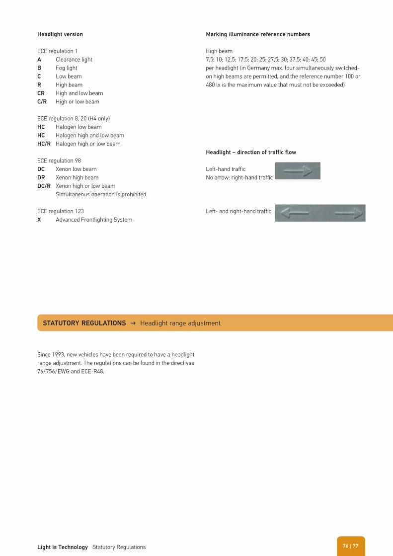
Headlight version
ECE regulation 1A Clearance lightB Fog lightC Low beamR High beamCR High and low beamC/R High or low beam
ECE regulation 8, 20 (H4 only)HC Halogen low beamHC Halogen high and low beamHC/R Halogen high or low beam
ECE regulation 98DC Xenon low beamDR Xenon high beamDC/R Xenon high or low beam Simultaneous operation is prohibited.
ECE regulation 123X Advanced Frontlighting System
Marking illuminance reference numbers
High beam7,5; 10; 12,5; 17,5; 20; 25; 27,5; 30; 37,5; 40; 45; 50per headlight (in Germany max. four simultaneously switched-on high beams are permitted, and the reference number 100 or 480 lx is the maximum value that must not be exceeded)
Since 1993, new vehicles have been required to have a headlight range adjustment. The regulations can be found in the directives 76/756/EWG and ECE-R48.
Headlight – direction of traffic flow
Left-hand trafficNo arrow: right-hand traffic
Left- and right-hand traffic
STATUTORY REGULATIONS → Headlight range adjustment
| 77Light is Technology Statutory Regulations 76
For Europe the main requirements are as follows: � The cleaning systems are subject to type approval according
to ECE R45 with regard to their cleaning power. � The fitting of such systems when gas discharge lights are
used has been compulsory since 1996 in compliance with ECE R48.
� Water reserves for 25 or 50 cleaning cycles (class 25, class 50)
� Cleaning efficiency of > 70 % on a headlight soiled to an extent that only 20 % of the original luminous flux is available
� Functional up to 130 km/h and from -10 °C to +35 °C
Due to the scope of the statutory regulations, only the most important are explained here. The following regulations contain all the relevant information about signal lights, their properties and uses.
76/759/EWG, ECE-R6, StVZO § 54
� Indicators front, rear and side
76/758/EWG, ECE-R7, StVZO §§ 51 and 53
� Clearance lights and taillights front and rear
77/540/EWG, ECE-R77, StVZO § 51
� Parking lights front and rear
ECE-R87
� Daytime running lights
77/539/EWG, ECE-R23, StVZO § 52
� Reverse lights
76/758/EWG, ECE-R7, StVZO § 53
� Stop lights
77/538/EWG, ECE-R38, StVZO § 53d
� Rear fog lights
76/760/EWG, ECE-R4, StVZO § 60
� Licence plate lights
ECE-R3
� Reflector
STATUTORY REGULATIONS → Headlight cleaning system
STATUTORY REGULATIONS → Signal lights
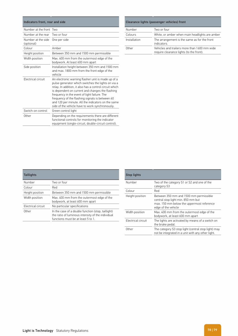
Indicators front, rear and side
Number at the front TwoNumber at the rear Two or fourNumber at the side(optional)
One per side
Colour AmberHeight position Between 350 mm and 1500 mm permissibleWidth position Max. 400 mm from the outermost edge of the
bodywork. At least 600 mm apartSide position Installation height between 350 mm and 1500 mm
and max. 1800 mm from the front edge of the vehicle
Electrical circuit An electronic warning flasher unit is made up of a pulse generator which switches the lights on via a relay. In addition, it also has a control circuit which is dependent on current and changes the flashing frequency in the event of light failure. The frequency of the flashing signals is between 60 and 120 per minute. All the indicators on the same side of the vehicle have to work synchronously.
Switch-on control Green control lightOther Depending on the requirements there are different
functional controls for monitoring the indicator equipment (single-circuit, double-circuit control).
Clearance lights (passenger vehicles) front
Number Two or fourColours White, or amber when main headlights are amberInstallation The arrangement is the same as for the front
indicators.Other Vehicles and trailers more than 1600 mm wide
require clearance lights (to the front).
Taillights
Number Two or fourColour RedHeight position Between 350 mm and 1500 mm permissibleWidth position Max. 400 mm from the outermost edge of the
bodywork, at least 600 mm apartElectrical circuit No particular specificationsOther In the case of a double function (stop, taillight)
the ratio of luminous intensity of the individual functions must be at least 5 to 1.
Stop lights
Number Two of the category S1 or S2 and one of thecategory S3
Colour RedHeight position Between 350 mm and 1500 mm permissible
central stop light min. 850 mm butmax. 150 mm below the uppermost reference edge of the vehicle
Width position Max. 400 mm from the outermost edge of thebodywork, at least 600 mm apart
Electrical circuit The lights are activated by means of a switch on the brake pedal.
Other The category S3 stop light (central stop light) may not be integrated in a unit with any other light.
| 79Light is Technology Statutory Regulations 78
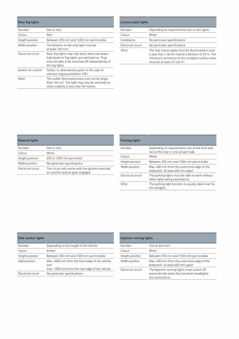
Rear fog lights
Number One or twoColour RedHeight position Between 250 mm and 1,000 mm permissibleWidth position The distance to the stop light must be
at least 100 mm.Electrical circuit Rear fog lights may only work when low beam,
high beam or fog lights are switched on. They must be able to be switched off independently of the fog lights.
Switch-on control Yellow, or alternatively green in the case of vehicles registered before 1981
Other The visible illuminated area must not be larger than 140 cm2. The light may only be switched on when visibility is less than 50 metres.
Side marker lights
Number Depending on the length of the vehicleColour AmberHeight position Between 250 mm and 1500 mm permissibleSide position Max. 3000 mm from the front edge of the vehicle
andmax. 1000 mm from the rear edge of the vehicle
Electrical circuit No particular specifications
Licence plate lights
Number Depending on requirements one or two lightsColour WhiteInstallation No particular specificationsElectrical circuit No particular specificationsOther The rear licence plate must be illuminated in such
a way that it can be read at a distance of 25 m. The minimum luminance of the complete surface area must be at least 2.5 cd/m2.
Daytime running lights
Number Two at the frontColour WhiteHeight position Between 250 mm and 1500 mm permissibleWidth position Max. 400 mm from the outermost edge of the
bodywork, at least 600 mm apartElectrical circuit The daytime running lights must switch off
automatically when the low beam headlightsare switched on.
Reverse lights
Number One or twoColour WhiteHeight position 250 to 1200 mm permittedWidth position No particular specificationsElectrical circuit The circuit only works with the ignition switched
on and the reverse gear engaged.
Parking lights
Number Depending on requirements two at the front and two at the rear or one at each side
Colour WhiteHeight position Between 350 mm and 1500 mm permissibleWidth position Max. 400 mm from the outermost edge of the
bodywork. At least 600 mm apartElectrical circuit The parking lights must be able to work without
other lights being switched on.Other The parking light function is usually taken over by
the taillights.
Installation regulations side viewSide marker lights (SML)Side marker reflector (SMR)
Installation regulations rear viewSide marker lights (SML)Side marker reflector (SMR)
Prescribed for vehicles > 6 m length, for vehicles < 6 m permissible
1
1
3
3
5
5
4
4
6
6
7
2
2
1 SML/SMR: max. 1,000 mm (from rear vehicle edge)2 All: max. 3,000 mm3 Indicator: max. 1,800 mm SML/SMR: max. 3,000 mm (from front vehicle edge)
1 Valid for indicator/stop light/tail light/reflector: max. 600 mm2 Valid for indicator/tail light/reflector3 High-mounted stop light: min. 850 mm4 Combination rearlight: min. 350 mm
4 SMR: max. 900 mm, SML: 1,500 mm5 SML/SMR: min. 250 mm6 SMR/SML: min. 250 mm, indicator: 350 mm7 SMR: max. 900 mm, SML/indicator: 1,500 mm
5 Combination rearlight: max. 1,500 mm6 High-mounted stop light: max. 150 mm below combination
rearlight or 3
| 81Light is Technology Statutory Regulations 80
One example The following can be found on a light RS1 IAF 02 E1 Æ 31483:
� R stands for tail light, � S1 for stop light, � IA for reflector, � F for rear fog light and 02 means that the regulation has
been revised twice since publication.
These features are integrated in the combination rearlight
� The E1 marking means that the light has been approved in Germany.
� The arrow shows which way the light can be installed and always points to the outer edge of the vehicle. If there is no arrow on the light it can be installed at the right or left rear side.
� The five-digit number at the end is the type approval number.
Help in decoding the combinations of numbers and letters on
signal lights
A Clearance lightAR Reverse lightF Rear fog lightIA ReflectorR Tail lightS1 Stop light1 Front indicator
(different technical design)1a Front indicator
(different technical design)1b Front indicator
(different technical design)2a Rear indicator5 Repeater flasher light at the side
(for vehicles up to 6 m in length)6 Repeater flasher light at the side
(for vehicles longer than 6 metres)SM1 Side marker light (for all vehicles)SM2 Side marker light (for vehicles up to 6 m in length)
Type approval numbers on signal lights
National and international design and operating regulations apply for the manufacture and testing of vehicle lighting equipment. Special approval marks exist for signal lights and can be found on the light.
The permissible light intensity values are different depending on the function involved. Lights indicating changes in movement (brakes = 60 cd) radiate stronger light signals than those for position and orientation (taillight = 4 cd).
S TaillightB StoplightZB Additional stoplightBL IndicatorZR Rear lightNES Rear fog lightPO Position light
1000
S
ECE USA ECE USA ECE USA ECE USAECE USA ECE USA ECE USA ECE USA
B ZB BL ZR NES PO BL
800
400
200
100
10
80
8
4
1
40
20
I �cd�
| 83Light is Technology Statutory Regulations 85
HELLA KGaA Hueck & Co.
Rixbecker Straße 7559552 Lippstadt, GermanyTel.: +49 2941 38-0Fax: +49 2941 38-7133Internet: www.hella.com
HELLA, Inc.
201 Kelly Drive, P.O. Box 2665Peachtree City, GA 30269Toll Free: 1-877-224-3552Fax: 1-800-631-7575www.hellausa.com
© HELLA KGaA Hueck & Co., Lippstadt9Z2 999 131-331 SCH/09.11/1.8Printed in Germany
HELLA Middle East FZE
Jebel Ali Free ZoneP.O. Box 17002LOB 19, Offi ce 502DubaiU.A.E. - United Arab Emirates
HELLA-New Zealand Limited
P.O. Box 5142781-83 Ben Lomond CrescentPakuranga, Auckland 2140 Telephone: (09) 577 0000Facsimile: (09) 576-2476Internet: www.hella.co.nz