lighting control history - university of...
TRANSCRIPT

LIGHTING CONTROL HISTORY
AND MODERN PROGRAMMING
STRATAGIES
Modern lighting control methods are governed by complex computer systems that make it possible to operate hundreds of lights at one time. They also make it possible to use the many digital lights and accessories developed over the past two decades. Although each manufacturer has its own particular method of handling technical issues, the core technology that makes all of them work is basically the same. This chapter is not intended to be an exhaustive review of every OEM system on the market, but rather as an overview of the basic philosophy that is used in designing digital products for the control of stage lighting. Each manufacturer publishes an operator’s manual that comes with their equipment. The manual is the best source of information about any type of system. Virtually every company makes these manuals available for download on-line, which is an excellent way to get information about new products. To understand the design philosophy used in creating the most modern systems, it is helpful to know a little bit about the history of stage lighting control. Like most technological areas, legacy conditions exist in entertainment lighting that manufacturers must satisfy when designing a new product. If the end users of a system are accustomed to working in a certain way, newer versions of the same product must take that into account in order to make them attractive to those end users. One obvious example of this is the use of cross-faders on modern computer boards, something that would probably
not exist if preset boards had not been their immediate technological predecessors. The first type of control for electrical lighting was simply a bank of switches that turned the lights on and off. Not surprisingly, artists in the theatre were not entirely satisfied with the “lights up, lights down,” nature of switches in controlling lighting for sensitive scenes. Not long after the use of electric lighting became widespread, resistance dimmers were developed so that it was possible to fade in and out of scenes. Fading indicates that the lighting change occurs over a period of time, which is an important element in lighting design. The term blackout is used to describe what happens when all of the stage lights go out instantly. (or as fast as the cooling filaments will allow) Although blackouts are frequently used to indicate a sudden end to the action on stage, they are not appropriate for most lighting changes. Lights fading in and out, or from one look to another is a very important concept in artistic lighting. Resistance dimmers were packaged together in groups, one beside the other, inside a wooden crate. Operating handles stuck out on one side so that stagehands, electricians, could fade the dimmers in and out. In later versions, there was a master control handle on the left-hand side that could be used to fade all the dimmers at one time. As explained in Chapter 3, resistance dimmers work by creating a voltage divider between the dimmer and the instrument lamp. As the handle of the dimmer rotated, the amount if resistance it created was raised and lowered. When resistance in a dimmer is high, voltage to the lamp is low and therefore the light is dim. When resistance in the dimmer is low, or off completely, voltage to the lamp is high and it shines with full intensity. One
1

interesting aspect of resistance dimmers was that they could operate equally well on either AC or DC power. Since lighting innovations of the time were mostly a reflection of what was happening on Broadway in New York, the capability of operating on DC power was important. Most theatres there in the early part of the 20th century were wired for DC because of the influence in that area of Thomas Edison and his power generating company.
A resistance board of the time was often called a piano board, possibly because of its outer wooden housing and the fact that it was “played” to change lights during the performance. Running a board of this type took some skill, because the operator had to count out the times of fades, and otherwise artistically manipulate the heavy metal handles and grating contacts of the resistance dimmers. If more dimmers were needed, another piano box was installed, along with a second operator, a third, etc. Dimmers in this time period tended to be of a large capacity, which meshed fairly well with the type of wash lights used. They covered big sections of the stage all at one time using banks of lights that were controlled by the same dimmer. Separate control of each light was simply not required by the standards of the time. The modern ideal of dimmer
per circuit was not economically feasible because that would require too many dimmers, and too many operators. After World War II, auto-transformer dimmers became widely popular. Electronically, the auto-transformer and the resistance dimmer are very different, but the physical operation is much the same in either case. Auto-transformer dimmers work by altering the voltage pressure by means of a variable transformer. In the theatre version, a large handle moves a coil of wire inside another coil of wire. The current in the primary induces a current in the secondary, and the normal rules governing transformer action apply. Altering the alignment of the primary and secondary and their physical proximity to one another affects the voltage output of the dimmer, and by extension, the brightness of the lamp.
2

One of the main advantages of this system over resistance dimmers was in the amount of power it consumed. A resistance dimmer uses the full current load any time a light is switched on, since it works as a voltage divider. Power is either consumed by the lamp by creating light, or consumed by the dimmer creating heat energy. On the other hand, except for a small internal loss, auto-transformers don’t consume any power themselves. The only power used is by the lamp. Auto-transformer dimmers were installed almost everywhere for several decades, except for a small number of theatres in New York, where only DC power was available. Like any transformer, the auto-transformer dimmer will operate only on AC power, not on DC. Although there were obvious monetary advantages to the auto-transformer dimmer so far as the theatre manager’s electric bill was concerned, control difficulty issues remained the same. It was still necessary to use a number of operators for any panel of more than a few dimmers, although complex mechanical master and submaster linkages were developed to make the job easier. Lighting panels were often located in the wings, just off the edge of the stage, so that the operators could take cues visually, as well as being warned by cue lights. Placing the dimmer panel close to the lights on stage also meant shorter cable runs for power circuits, just as it does today. The greatest technological leap for stage lighting, which would make future computer control possible, was the development of solid-state dimmers that could be controlled from a remote location. Although there have been many improvements over the years, the invention of the SCR or silicon-controlled rectifier, made all of the later technology possible.
A very early version of this switching device was the Thyratron tube, similar in appearance to an old radio tube. Thyratron tubes were designed to turn current on and off very rapidly when signaled by a separate control current. Thyristors are the modern, solid-state version of the older tube types. Solid-state devices such as transistors and diodes do the same work as their old tube ancestors, but are made from solid pieces of semi-conductor material rather than vacuum tubes, and are much more reliable. “Thyristor” refers to a family of semiconductor switching devices, one of which is the SCR. Some modern dimmers used slightly different components, but the general electronics of how they alter the voltage in an AC circuit remain essentially the same.
Modern electronic dimmers vary the voltage pressure to a lamp by switching the current on and off very rapidly. In the
3

case of an SCR, a control voltage applied to the gate of the SCR tells it when to conduct. When the line voltage of the circuit drops to zero as it crosses the x axis of the sine wave graph, the SCR shuts off and stops conducting. It must be told by the control circuit to begin conducting again for each cycle of AC current. The control circuit can vary the precise moment that conduction begins. You will remember that the effective voltage of a sine (or any other curve) wave is expressed by its root mean square, or RMS. Although not technically an average voltage, it is helpful in this case to visualize it as that.
The graph shows how much time the wave spends conducting, and what affect this has on the RMS voltage. If the control circuit tells the SCR to begin conducting late in the cycle, a smaller voltage is produced. If conduction begins sooner, a larger voltage is produced. SCRs conduct in one direction only, somewhat like a diode, so in order to make use of the entire sine wave, two inversely mounted SCRs are generally used. ETC’s dimmer doubling works by splitting the sine wave into upper and lower parts, one circuit using the top half, and the other the bottom half. In a commercially produced dimmer, the SCRs are somewhat easy to spot because they are almost always mounted on a heat-sink, so that any excess heat they produce can be dissipated.
The earliest control boards that could take advantage of electronic dimmers came about in the late 1950s, before computers were commonly available. They worked on the principle of setting up presets, which were used by designers to set up a look on stage. A look is a specific set of light values created by dimmers that produces an overall effect on stage that the designer wants to see. Quite frequently, designers work by setting up a specific look for a scene, and then varying it to support the action of the play as time passes. If the action of the play returns to the same location several times, the same look, or a variation of it, may be reused each time the action returns. This method of working developed from the use of presets, which could be made up in advance of the cue happening. A group of sliders are pre-set in advance of the cue. One of the earliest examples of this was the two-scene preset board, which was very popular in the 1960s. The board was constructed with two sets of sliders, or potentiometers. These were often called banks, and were labeled X/Y or A/B. Each bank had one potentiometer for every dimmer in the system, perhaps 1 through 64. The sliders in a bank were set to specific levels to arrive at a look on stage. The operator could set up the next preset while the first was still in use.
4

Crossfaders were used to make a smooth change from one preset to the next. A pair of inversely proportional sliders made up the crossfade unit. One read 10 (full) when all the way up, and the other 10 when all the way down. The operator moved both of these in tandem, causing one scene to fade up while the other faded down. This was a huge breakthrough in operation technology because one electrician could handle the entire job, and with much more accuracy. The board could be separated from the dimmers because a small (for the times) cable was used to send the control signal from the board to the dimmers themselves. This was an analog signal, usually 0 to 10 volts, which was attenuated by the various sliders involved. If the next cue meant adjusting only one light, the operator would often just move that one particular slider in the bank rather than going to a whole new preset, which took a few moments to set up. If a series of cues needed to come rapidly one after the other, it might be difficult for the operator to keep up the pace, so something else was needed. A refinement of the two-scene board was the preset panel. This panel was separate from the control board and required a second operator to use. The second electrician set up the banks of presets on the panel, which might have as many as ten different banks. This created a backlog of 9 presets, and gave some extra time for the electricians to set things up between hectic moments. The operator’s board had buttons to assign a specific bank of sliders to a specific crossfader. Card-reading boards were a very interesting technological cul-de-sac in the 1970s. They are worth mentioning here because they were a low-tech means of mimicking the way that a modern computer system reads cues. The “cards”
in this case were printed circuit boards with many small knobs on them. Each of these knobs was connected to a tiny potentiometer, one for each dimmer in the system. In “programming” the show, the designer would establish looks that were recorded by adjusting all of the pots on one card. That card was set aside, and another one inserted when programming the next cue. The cards were numbered using a grease pencil, and put aside for use in running the show. This is strikingly similar to programming a computer board, but in a mechanical way that was the only thing possible with the technology of the period. The card reading idea faded out rapidly because it had so many moving parts that at least one was bound to fail sooner rather than later, and because computer systems were available shortly there after. It is interesting to note that the methodology of setting levels on the card reader in that era was the same as setting levels on a computer monitor in this one, but technology has made the process much more efficient.
Computer boards such as the Kliegl Performer® were a huge change in the lighting design and technology fields, but it is easy to see how they were directly related to earlier types. A card reading board’s information was mechanically
5

stored in the cards themselves. A computer stores information digitally, and even considering the very small memories available in the early 1980’s, this was a giant leap forward in technology. In reality, the amount of memory space required to store cues for a lighting design is actually quite small by modern standards, when compared to a picture or music file. Currently manufactured ETC boards can store an entire show on one floppy disk, which is only 1.44MB. Interestingly, the Performer series of light boards employed a cassette tape storage system that is no longer used. Early computer systems stored information digitally, but the output to dimmers was the same 10VDC control voltage as was used in a preset board. A rather thick multicable was required for control purposes. Each dimmer was controlled by one wire for the + signal which carried information about the desired dimmer level from the board to the dimmer rack, while a common ground was used for each group of 32 dimmers. In a 64 dimmer system, that would mean at least 65 conductors. In the Performer, connections were made using what is now known in modern computerese as a parallel port connector.
A careful study of the Performer’s keyboard shows its close affiliation with earlier preset board types. Most notably, there is an A/B fader that has A full at the top, and B full at the bottom. This was so that the operator could manually fade
from one cue to another as was done on a preset board. As an alternative, the operator could use the X or Y fader, which would make the cue happen at the press of the button. This illustrates an important difference between a computer board and any earlier type, the ability of the machine itself to complete a cue over a period of time, with no help from the operator. The fast/slow buttons were used to speed up a lengthy cue to save time when reviewing cues while programming the show. An interesting feature of this board was the inclusion of a backup feature at the left-hand side of the keyboard. The on off switch can be seen at the far left. DIP switches were used to assign one or more channels to each of the sliders. This same type of switch is still used today to address some types of digital equipment. By carefully assigning channels into useful groups, and then manipulating them manually, the operator could run a show even if the computer crashed. Modern control systems don’t generally have a backup mode, perhaps because they are more reliable, but more likely because people have become much more trusting of computer systems in general, and lighting systems in particular. It would not be possible to use most of today’s accessory equipment with an analog signal, so digital signals are used instead. DMX 512 The modern protocol, or system of rules governing the way that the computer and dimmers communicate with one another is known as DMX 512A. DMX 512 stands for “Digital Multiplexing 512” the method used by lighting equipment manufacturers to send information from a
6
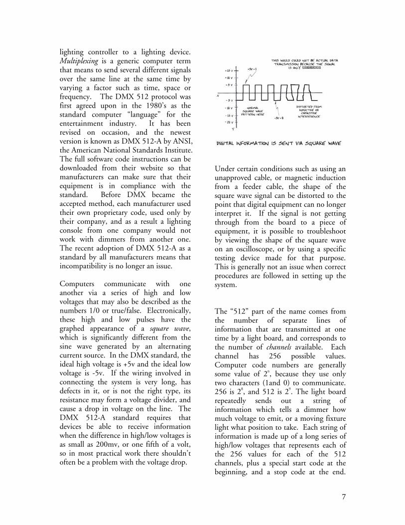
lighting controller to a lighting device. Multiplexing is a generic computer term that means to send several different signals over the same line at the same time by varying a factor such as time, space or frequency. The DMX 512 protocol was first agreed upon in the 1980’s as the standard computer “language” for the entertainment industry. It has been revised on occasion, and the newest version is known as DMX 512-A by ANSI, the American National Standards Institute. The full software code instructions can be downloaded from their website so that manufacturers can make sure that their equipment is in compliance with the standard. Before DMX became the accepted method, each manufacturer used their own proprietary code, used only by their company, and as a result a lighting console from one company would not work with dimmers from another one. The recent adoption of DMX 512-A as a standard by all manufacturers means that incompatibility is no longer an issue. Computers communicate with one another via a series of high and low voltages that may also be described as the numbers 1/0 or true/false. Electronically, these high and low pulses have the graphed appearance of a square wave, which is significantly different from the sine wave generated by an alternating current source. In the DMX standard, the ideal high voltage is +5v and the ideal low voltage is -5v. If the wiring involved in connecting the system is very long, has defects in it, or is not the right type, its resistance may form a voltage divider, and cause a drop in voltage on the line. The DMX 512-A standard requires that devices be able to receive information when the difference in high/low voltages is as small as 200mv, or one fifth of a volt, so in most practical work there shouldn’t often be a problem with the voltage drop.
Under certain conditions such as using an unapproved cable, or magnetic induction from a feeder cable, the shape of the square wave signal can be distorted to the point that digital equipment can no longer interpret it. If the signal is not getting through from the board to a piece of equipment, it is possible to troubleshoot by viewing the shape of the square wave on an oscilloscope, or by using a specific testing device made for that purpose. This is generally not an issue when correct procedures are followed in setting up the system. The “512” part of the name comes from the number of separate lines of information that are transmitted at one time by a light board, and corresponds to the number of channels available. Each channel has 256 possible values. Computer code numbers are generally some value of 2n, because they use only two characters (1and 0) to communicate. 256 is 28, and 512 is 29. The light board repeatedly sends out a string of information which tells a dimmer how much voltage to emit, or a moving fixture light what position to take. Each string of information is made up of a long series of high/low voltages that represents each of the 256 values for each of the 512 channels, plus a special start code at the beginning, and a stop code at the end.
7

The start and stop codes are used to synchronize the transmission of the code by the light board and its reception by a device. Most electricians won’t need to understand the intricacies of the code itself, but understanding that there is one makes it easier to understand how the system as a whole operates. When the DMX 512 standard was set up in the 1980’s it was seen only as a way to control dimmers, and not all of the digital equipment in use today. It seemed unlikely at the time that any installation would have more than 512 dimmers, which even now would be a very large number of them. As time passed and digital control of accessory equipment became important, it became obvious that 512 channels would not be enough, especially when using moving lights, which typically require either 16 or 24 channels for each fixture. The DMX standard was set at 512 channels and it was not possible to add more to it without making all previous equipment obsolete. Instead, manufacturers began to use more than one set of DMX in a single light board. One group of DMX became known as a universe, because it is its own complete world, not connected to any other. It is common for a lighting console to contain two or three universes, and at least one automated board has six universes for working with moving fixture lights. A recently manufactured light board may have multiple 5 pin XLR outputs, one for each universe. They will be numbered 1-512, 513-1024, and so forth. Another very interesting and important development used in digital control equipment from the very beginning was the use of channels in setting up data recording. Dimmers are real, physical devices that control the intensity of lighting fixtures. A channel on the other
hand is a pathway for information to flow down, and is similar in concept to a television channel. TV channel 22 has one program on it, and channel 37 has another. Information from a cable or satellite provider flows into the television and a program appears on the screen. Information from the lighting computer flows down a control cable to one or more dimmers, and they in turn cause one or more lights to change brightness. Channels only exist in the digital realm and are really just a means of assigning information to different devices. A channel does not necessarily have to be connected to a dimmer. Accessories like a color changers and gobo rotators also have assigned channel numbers. It is possible to connect more than one dimmer to one channel, but it is not possible to assign more than one channel number to the same dimmer, which would not be productive in any case.
Channels and dimmers can be connected with one another by what was once known as soft-patching, and now simply patching. Although a modern dimmer-per- circuit system has a dimmer for every outlet, early systems generally had a smaller number of dimmers and a larger number of circuits (outlets). A patch panel was used to connect one or more circuits to a dimmer. If the lights in
8

circuits 12, 20, and 58 were designed to always be on at the same value and at the same time, they could all be patched into the same dimmer for convenience and to save on occupying a limited number of dimmers. That approach made sense in a time when dimmers were controlled by hand, and operating too many would be physically difficult. In the present day, all of the dimmers in a system are manipulated by one electrician, literally at the press of a button, so a large number of dimmers has become an asset rather than a liability. A patch panel was a real, physical entity, but soft-patching occurs only in the computer’s memory. After the appropriate menu is selected, dimmers or other accessories are matched with channel numbers. This can be a distinct advantage for a designer or technician, because consecutive channel numbers can be chosen for lights that will commonly be used together, regardless of what circuit/dimmer they may be plugged into. This makes the numbers much easier to remember. Entering the patch is guided by use of the hookup sheet, a spreadsheet like document that lists all of the channels in use, and the dimmers that are connected to them. If digital lights and accessories are used, their addresses should also be on the hookup sheet. Frequently, the exact circuits/dimmers used are not known until after the light hang is completed, and as a result the hookup cannot be established until late in the process.
Electronic Theatre Controls or ETC® is currently the most popular brand of lighting control equipment used in the United States. As a result, many of the methods described here are those which are used on ETC brand equipment, such as the Insight, Express, and Expression. Most other brands of controllers use very similar techniques, but the exact keystrokes used may be slightly different. The correct keystrokes for any specific manufacturer’s equipment can be found in the manual for their specific console.
9

After all the lights have been hung and cabled, and the patch has been established, the work of programming the cues can begin. Usually this involves the input of a designer who tells the electrician what levels to set, but may simply be the designer herself sitting down at the board. Artistic concerns are covered separately, and this section covers the technical issues of how cues are developed and recorded. The narrative of this chapter reveals the general flow of the work, there are specific “cheat sheets” at the end which describe the exact cue strokes used to manipulate the cueing process.
Most designers work by establishing a series of looks, and then modifying them for particular moments in the performance. A look is created by setting levels for the dimmers in the system, and by programming digital equipment to perform specific tasks like the speed of a gobo rotator, or the position of a color changer gel string. On occasion, a look might include a looped cue, one which repeats a movement on a moving light, or a linked series of fades up and down. Most of the time, a look is a static view of light distributed across the stage.
The designer works primarily from the magic sheet, a type of paperwork that lists how systems of light fall on the stage. A magic sheet is generally a plan view of the setting with arrows and numbers telling what channel controls face light, side light, specials etc. There may be a number of these in order to list all of the lights used for a particular design. Every designer has her own favorite method of making up the magic sheets. Channels are brought up separately or in groups to light the stage. The designer might want channels 5 and 7 at 30%, 11 at 20%, and so forth in a particular cue. Most of the time a cue is built one channel at a time until the desired look is accomplished. Quite often, the exact level
10
of the channel is not known in the beginning, and instead of saying “channel 5 at 50%” the designer might say “lets see channel 5 at about half”, and then the final tweaking is done by using an adjustment wheel, or some other similar device. The Expression family of control boards has a moveable wheel to the right of the keypad that allows the user to ramp selected channels up or down by rotating it. Channel selection through the numeric keypad is made easier by the function keys found just to the right of it. The and key allows several numbers to be added in and manipulated all at the same time, for example 4 and 5 and 7 and 8, which can then all be set at the same level. The – or through key, allows for a sequential series of numbers, for example 4 through 8, to all be selected and together set at a specific level. The at key is used to preface entering a level command, such as channel 8 at 40%. If a channel is to be set at 100%, the at key may be omitted, and the full key used instead. Submasters are frequently used to speed up the cuing process. They do this by grouping together sets of channel numbers and values so that they all work as one unit. If one look is to be re-used a number of times, it can be recorded as a submaster, so that it is easily recalled. Sometimes systems of light are put into a sub so that they can be brought up as a group on the way to creating a look. For example, red cyc lights in one sub, green and blue in others. Submasters are also a very convenient way to manipulate moving lights, or for setting the values of a number of color changers all at one time. The next step in programming a show on a lighting console is to record each look or other type of change as a cue number. On an ETC product, the record and enter
buttons are used to do this, along with the numerical keypad. Generally speaking, the cues are numbered sequentially, one after the other so that they will be in order for playback. A problem arises when adding cues later on. Additional cues are frequently added during dress rehearsals, so inserting cues is necessary and can be done by using the “.” key. ETC allows two decimal places on a cue number, so it is possible to have a cue sequence such as 24, 24.1, 24.15, 24.2, 25. Each cue number must have a period of time associated with it. The time of the fade is recorded in seconds using the time key from the left of the numerical keypad. There are actually two timing sequences to most cues, a fade up time and a fade down time. These two sequences can be manipulated separately. The need for separate up/down times is rare, but on occasion you may wish to have a light linger for a moment after others have faded, or to have a light establish itself before others come up. In that event, it is necessary for one fader to lead and the other lag, so separate time amounts need to be entered when prompted by the screen. If a straight cross fade is required, entering a time in seconds and pressing the enter button twice will make the up and down times the same. After cues are set, it is important to save show to preserve the cues for the future. Saving is done by inserting a 3.5 inch floppy disk, accessing the set up menu, navigating to disk functions, and then write all to disk. It is important that the disk be formatted as IBM compatible. Disk formatting can be done by the board, but that will erase any data on the disk, so make sure that nothing you will need later is on it before formatting. It is important to make two copies of the disk, because the floppy disk storage method is far from infallible. If the console is left turned on,
11

and the monitors are switched off when ending a session, cues should remain in the board with no problem, but an uninterrupted supply of power is difficult to guarantee. To load cues into the console, press the set up button, and choose read all from disk. It is important to realize that the commands write all to disk, and read all to disk, control more than just the cues that have been written and stored in the console’s memory. These commands also include the patch and submaster settings, as well as any other information you have entered regarding dimmer profiles, personalities, etc. The command read show from disk will read only the cues and not the other information. If you wish to keep the same patch and submaster settings, perhaps for a repertory plot, use the read show command. If an ETC console is connected to an Emphasis server, saving is done on the server instead. In this case, server means the accompanying PC. If Emphasis is in use, go to File > Save Show> enter the name of your show, and save. Your cue file will be saved on the shows drive. It is sometimes a good idea to save the cues on a secondary device, and since the server has USB ports on the back, a travel drive is the best option. Follow the process of: Save As > Travel Drive > Enter Show Name > Save. Saving on the travel drive will ensure that you cues survive even if the PC server crashes for some reason. It is often helpful to use the save as command to save different versions of the same show. Occasionally changes are made in the cuing that the designer would like to revert to later on. If the same show file is written over after each rehearsal using the save command, there will be no existing record of what cues were previously set. If the show is saved using
save as after each rehearsal, and a new name is used, it will be possible to search backward for lost information. Although most of the methods and commands used on ETC equipment is the same from one model to the next, it is interesting to note one important difference between the Expression and Express consoles. The Express has a slider on the console for each of the channels used as dimmers. As a result, the sliders can be used to set levels for the various dimmers rather than going through the regular keypad commands. This is an excellent time saving measure, but is meant for systems with relatively few dimmers, as it would not be practical to have a console with hundreds of sliders on it. The Express console design makes it easier to work “on the fly” when it is not possible to program cues for a show because of time constraints. If panel tape is used to mark the purpose of each slider, the board operator can follow along as best she can. This method of working should not be considered ideal, but often occurs in an educational facility. TERMS USED IN THIS CHAPTER OEM
Legacy condition
Fade
Blackout
Look
Electrician
Piano board
Dimmer per circuit
Auto transformer
Cue light
Power circuit
12

Solid-state
Silicon controlled rectifier or SCR
Thyratron tube
Thyristor
Root mean square or RMS
Heatsink
Preset
Two-scene preset Board
Slider
Crossfader
Preset panel
Card-reader
DIP switch
Protocol
DMX512A
Multiplexing
Square wave
Channel
Universe
5 pin XLR
Patch
Hookup sheet
ETC
Magic sheet
Wheel
Commands: AT, AND, THROUGH, FULL
Submaster
Cue number
Record
Enter
Fade up
Fade down
Write all to disk
Read all from disk
3.5” floppy
Read show from disk
Emphasis
Save
Save as
Show drive
13