lighting, texturing and rendering the 3d model · 2012-03-29 · vectorworks 2008 tutorial -...
TRANSCRIPT
VectorWorks 2008 Tutorial #3
* * * Lighting, Texturing and Rendering the 3D Model * * *written by Kent Goetz
revised 8/11/2008http://instruct1.cit.cornell.edu/courses/thetr263/index.html
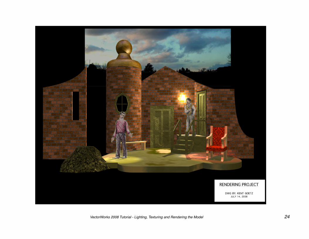
This tutorial contains a set of instructions designed to lead the user through a series of activities that one may encounter when designing a scenic space. An example of the completed tutorial project is provided on the last page. The tutorial project does not represent a design for any specific play. The project is simply a composition of basic units composed in a theatrical situation designed to introduce the user to the basic tools and commands of VectorWorks.
The tutorial assumes that the user has a basic knowledge of either Macintosh or Windows operating systems and a general understanding of stage terminology, i.e. stage left is actually the audiences right, upstage is farther away from the audience, etc.. If the tutorial is successful, then upon completion the user should feel both motivated and sufficiently skilled to continue exploring more complex and creative ways to employ this application.
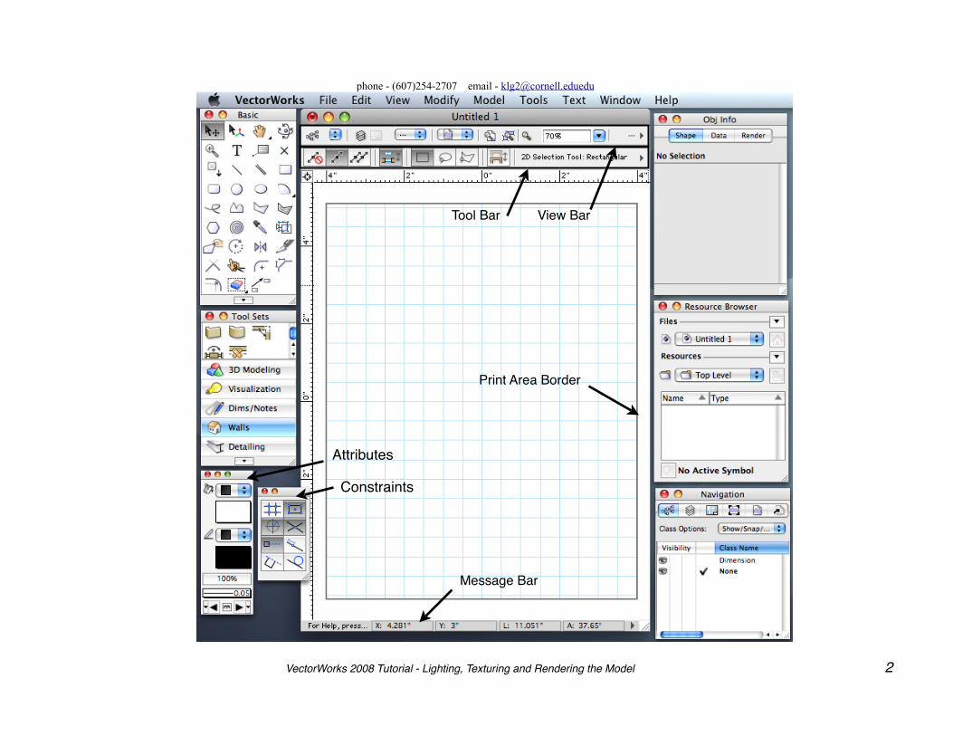
On the next page is a diagram of the VectorWorks interface, followed by an illustration showing VectorWorks keyboard shortcuts. Please familiarize yourself with these pages before you begin the tutorial instructions which follow. It is advisable to execute each step of the tutorial sequentially and to read through each activity completely before executing. Referring often to the example of the completed project can also be helpful. Please note that as you progress through the tutorial the instructions become less specific assuming that you have been acquiring skills as you execute the various tutorial activities. For increased retention of skills, it is suggested that after executing 5-10 actions by reading the tutorial instructions, you Undo those actions and execute them again without reading the instructions.
This tutorial was written using the Macintosh operating system. Some illustrations may have a different appearance for those using Windows, and some menu commands and keyboard shortcuts may be different, i.e., on the Mac the , or Command key, is the Control key in Windows, Option = Alt , Delete = Backspace, Return = Enter, et al.
Note: -- To execute this tutorial completely you will need: 1) the Spotlight version of VectorWorks with RenderWorks; 2) a completed project from the “Modeling Scenic Space” tutorial or the sample file “VWTutrlModeling.vwx” ; and 3) the image files: “Clouds.jpg”; “Figure1.jpg”; Figure2.jpg”; “Pattern.bmp”; and “Popcorn.jpg”. All files are available through the tutorial website.
Applications used to create tutorial:VectorWorks 2008 by Nemetschek, North America, Pages ‘08 by Apple.
Snapz Pro X by Ambrosia Software Inc. For permission to copy and distribute this document contact:Kent Goetz, 937 Harford Slaterville Rd., Dryden , NY 13053
phone - (607)254-2707 email - [email protected]
View Bar
Print Area Border
Tool Bar
Message Bar
Constraints
Attributes
VectorWorks 2008 Tutorial - Lighting, Texturing and Rendering the Model 2
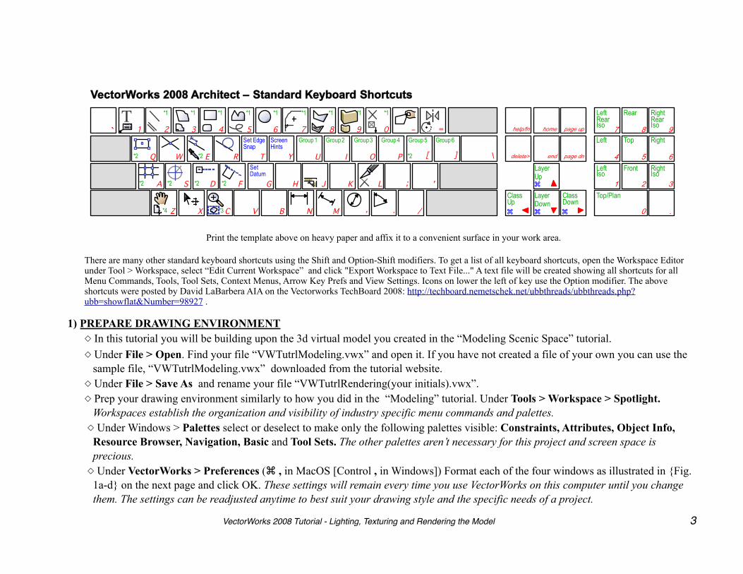
Print the template above on heavy paper and affix it to a convenient surface in your work area.
There are many other standard keyboard shortcuts using the Shift and Option-Shift modifiers. To get a list of all keyboard shortcuts, open the Workspace Editor under Tool > Workspace, select “Edit Current Workspace” and click "Export Workspace to Text File..." A text file will be created showing all shortcuts for all Menu Commands, Tools, Tool Sets, Context Menus, Arrow Key Prefs and View Settings. Icons on lower the left of key use the Option modifier. The above shortcuts were posted by David LaBarbera AIA on the Vectorworks TechBoard 2008: http://techboard.nemetschek.net/ubbthreads/ubbthreads.php?ubb=showflat&Number=98927 .
1) PREPARE DRAWING ENVIRONMENT◇ In this tutorial you will be building upon the 3d virtual model you created in the “Modeling Scenic Space” tutorial.◇ Under File > Open. Find your file “VWTutrlModeling.vwx” and open it. If you have not created a file of your own you can use the
sample file, “VWTutrlModeling.vwx” downloaded from the tutorial website. ◇ Under File > Save As and rename your file “VWTutrlRendering(your initials).vwx”.◇ Prep your drawing environment similarly to how you did in the “Modeling” tutorial. Under Tools > Workspace > Spotlight.
Workspaces establish the organization and visibility of industry specific menu commands and palettes. ◇ Under Windows > Palettes select or deselect to make only the following palettes visible: Constraints, Attributes, Object Info,
Resource Browser, Navigation, Basic and Tool Sets. The other palettes aren’t necessary for this project and screen space is precious.
◇ Under VectorWorks > Preferences ( , in MacOS [Control , in Windows]) Format each of the four windows as illustrated in {Fig. 1a-d} on the next page and click OK. These settings will remain every time you use VectorWorks on this computer until you change them. The settings can be readjusted anytime to best suit your drawing style and the specific needs of a project.
9
6
7 8
4 5
3 1 2
0 .
page up home
page dn end
help/fn
delete>
Z
9
X C V B N M , . /
A S D F G H J K L ; '
Q W E R T Y U I O P [ ]
1 2 3 4 5 6 7 8 0 – =
\
`
VectorWorks 2008 Architect – Standard Keyboard Shortcuts
Right Rear Iso
Rear Left Rear Iso
Front LeftIso
Right Top Left
Top/Plan
Right Iso
LayerDown
ClassUp
LayerUp
ClassDown
T
Group 1 Group 2 Group 3 Group 4 Group 5 Group 6Screen Hints
Set Edge Snap
Set Datum
*3
*2*2*2
*2 *2
*4
*1 *1 *1 *1 *1
*2
*2
*1 *1 *1 *1
VectorWorks 2008 Tutorial - Lighting, Texturing and Rendering the Model 3
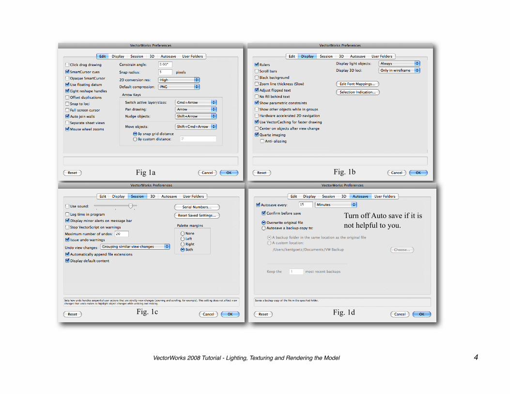
Fig 1a
Fig. 1b
Fig. 1c
Fig. 1d
Turn off Auto save if it is not helpful to you.
VectorWorks 2008 Tutorial - Lighting, Texturing and Rendering the Model 4
2) LIGHTING THE SCENE
Note: In order to fully benefit from the lighting features of VectorWorks you need to have RenderWorks installed.
◇ Go to the “3dPersp Solid” view.◇ Under View > Rendering > Fast RenderWorks. Your set will turn a medium gray with a shadow side to the objects.
Renderworks automatically places in the space an arbitrary directional light. We will replace it shortly.◇ Save this view as “3dRender”. The Fast RenderWorks renderer is a very basic rendering engine that suggests the
general direction, intensity, shape, and color of light on a surface. It does not display shadows. It is a quick way of roughing in lighting effects. You will switch to a more realistic, but slower, renderer after you have placed all your lights.
◇ Under VectorWorks > Preferences. Click the Display tab and make sure Always is checked under Display Light Objects.
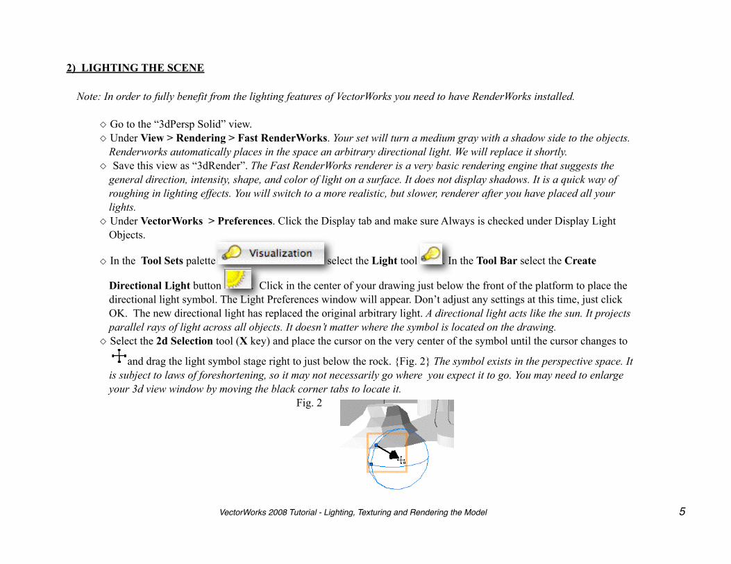
◇ In the Tool Sets palette select the Light tool . In the Tool Bar select the Create
Directional Light button . Click in the center of your drawing just below the front of the platform to place the directional light symbol. The Light Preferences window will appear. Don’t adjust any settings at this time, just click OK. The new directional light has replaced the original arbitrary light. A directional light acts like the sun. It projects parallel rays of light across all objects. It doesn’t matter where the symbol is located on the drawing.
◇ Select the 2d Selection tool (X key) and place the cursor on the very center of the symbol until the cursor changes to
and drag the light symbol stage right to just below the rock. {Fig. 2} The symbol exists in the perspective space. It is subject to laws of foreshortening, so it may not necessarily go where you expect it to go. You may need to enlarge your 3d view window by moving the black corner tabs to locate it.
Fig. 2
VectorWorks 2008 Tutorial - Lighting, Texturing and Rendering the Model 5
NOTE: To avoid the screen redrawing every time you make an adjustment, type ( . ) to cancel the redraw. And to force a screen redraw hit the Z key twice.
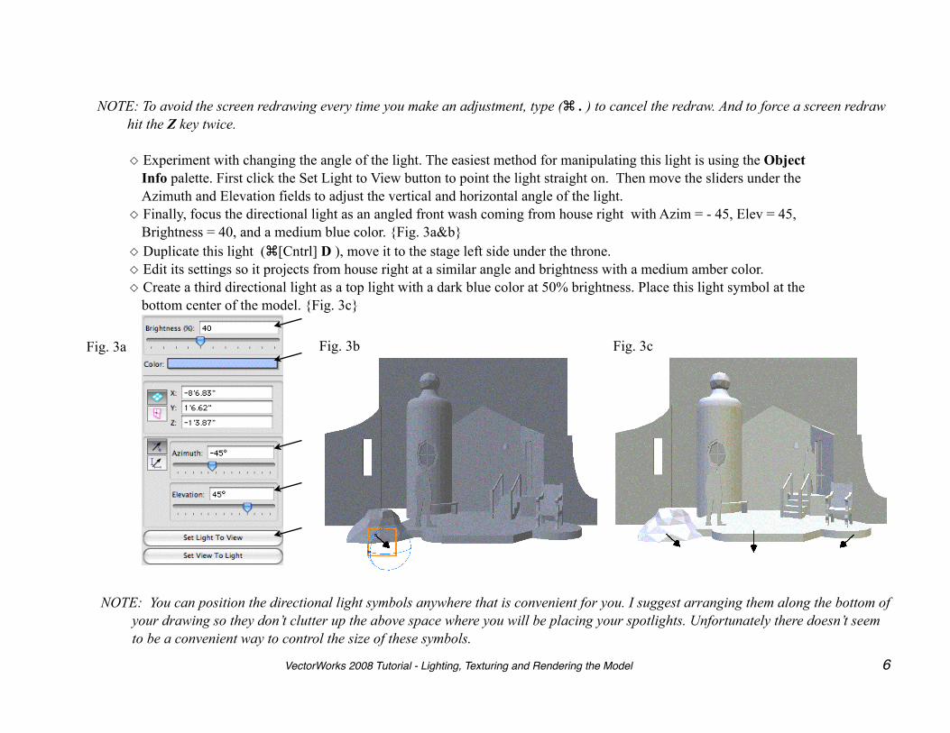
◇ Experiment with changing the angle of the light. The easiest method for manipulating this light is using the Object Info palette. First click the Set Light to View button to point the light straight on. Then move the sliders under the Azimuth and Elevation fields to adjust the vertical and horizontal angle of the light.
◇ Finally, focus the directional light as an angled front wash coming from house right with Azim = - 45, Elev = 45, Brightness = 40, and a medium blue color. {Fig. 3a&b}
◇ Duplicate this light ([Cntrl] D ), move it to the stage left side under the throne.◇ Edit its settings so it projects from house right at a similar angle and brightness with a medium amber color.◇ Create a third directional light as a top light with a dark blue color at 50% brightness. Place this light symbol at the
bottom center of the model. {Fig. 3c}
Fig. 3a Fig. 3b Fig. 3c
NOTE: You can position the directional light symbols anywhere that is convenient for you. I suggest arranging them along the bottom of your drawing so they don’t clutter up the above space where you will be placing your spotlights. Unfortunately there doesn’t seem to be a convenient way to control the size of these symbols.
VectorWorks 2008 Tutorial - Lighting, Texturing and Rendering the Model 6

◇ Select the Light tool again and in the Tool Bar select the Create Point Light button . ◇ Go to the “3dFront” view, zoom in and click on the sconce at the center wall to place a light source inside the wall
sconce. {Fig. 4a}◇ Go to the “3dPlan” view, zoom in and reposition the point light so it is centered inside the sconce. {Fig. 4b} Change
its brightness to 50% and its color to a light amber.◇ Return to the “3dRender” view to view results. {Fig. 4c}
Fig. 4a Fig. 4b Fig. 4c
NOTE: Light symbols that are placed amongst 3d objects may be obscured when they are deselected. You may have to return to a wireframe view to find them in order to select them again.
◇ Select the Light tool again and in the Tool Bar select the Create Spot Light button . ◇ Go to the“3dFront” view. Scroll up so you can see the top of the backdrop, and click once in the center of your
drawing just below the top of the backdrop to place a spot light, drag the focus line down to the throne to focus on it, and click to set {Fig. 5a} Notice in the Object Info palette the light has a Z coordinate, or height above the ground plane..
VectorWorks 2008 Tutorial - Lighting, Texturing and Rendering the Model 7
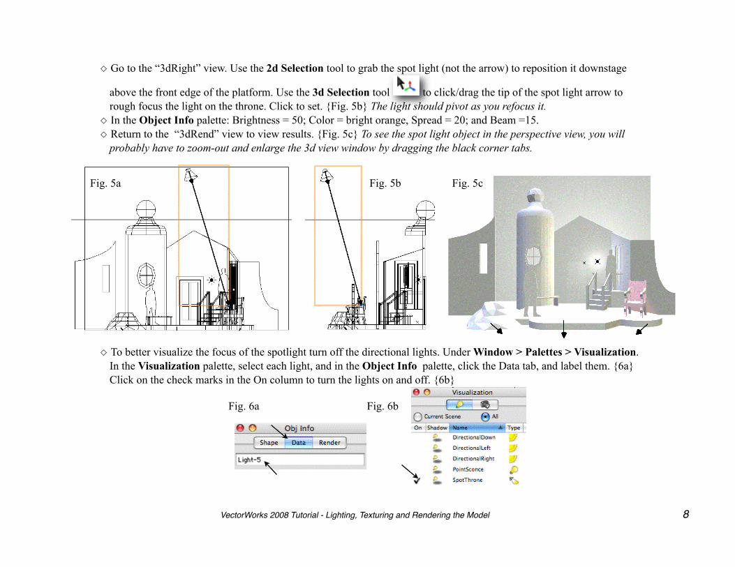
◇ Go to the “3dRight” view. Use the 2d Selection tool to grab the spot light (not the arrow) to reposition it downstage
above the front edge of the platform. Use the 3d Selection tool to click/drag the tip of the spot light arrow to rough focus the light on the throne. Click to set. {Fig. 5b} The light should pivot as you refocus it.
◇ In the Object Info palette: Brightness = 50; Color = bright orange, Spread = 20; and Beam =15.◇ Return to the “3dRend” view to view results. {Fig. 5c} To see the spot light object in the perspective view, you will
probably have to zoom-out and enlarge the 3d view window by dragging the black corner tabs.
Fig. 5a Fig. 5b Fig. 5c
◇ To better visualize the focus of the spotlight turn off the directional lights. Under Window > Palettes > Visualization. In the Visualization palette, select each light, and in the Object Info palette, click the Data tab, and label them. {6a} Click on the check marks in the On column to turn the lights on and off. {6b}
Fig. 6a Fig. 6b
VectorWorks 2008 Tutorial - Lighting, Texturing and Rendering the Model 8

◇ Go to the “3dFront” view. Select and duplicate the spot light and move it stage right 18“. Change its color to a bright amber. {Fig. 7a} You will have to click the Shape tab in the Object Info palette to see the light specifications.
◇ Return to the “3dRender” view. Use the 3d Selection tool to click/drag the tip of the spot light arrow to rough focus the light on the stage right figure by the rock. You will notice a dotted line along the floor that indicates where the light is focusing on the ground plane. {Fig. 17b}
◇ Select each spot light and in the Object Info palette, adjust the beam size by dragging the inside beads to create a narrow beam. {Fig. 7c} The beam is a cone of light that does not change intensity. The spread is a cone of light larger than the beam that determines the sharpness or softness of the beam . The closer the spread is to the beam the sharper the circle of light. Fine tune the focus by dragging the Pan and Tilt sliders in the Object Info palette. {Fig. 7d}
Spread
Beam
Fig. 7a Fig. 7b Fig. 7c
Fig. 7d
◇ Return to the “3dFront” view. Place a new spotlight at the center of the backdrop and focus it straight down. {Fig. 8a} ◇ Go to the“3dRight” view and move the spotlight upstage of the back wall, then focus it upstage at the center of the
backdrop. {Fig. 8b} Go to the “3dPlan” view to make sure the light is focused straight upstage. {Fig. 8c} In the Object Info palette make both the Spread and Beam 180˚ (beads wide open), deselect Cast Shadows, make Brightness = 75% and color white.
VectorWorks 2008 Tutorial - Lighting, Texturing and Rendering the Model 9
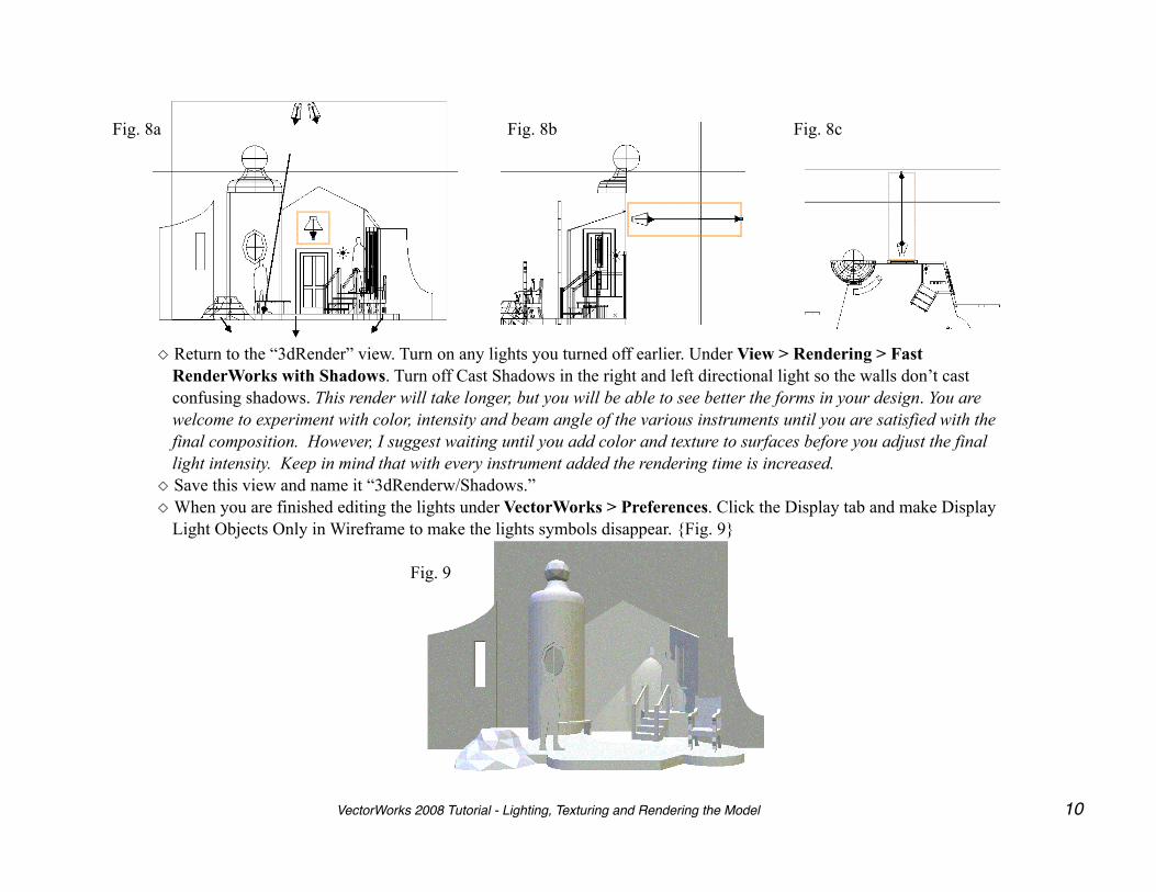
Fig. 8a Fig. 8b Fig. 8c
◇ Return to the “3dRender” view. Turn on any lights you turned off earlier. Under View > Rendering > Fast RenderWorks with Shadows. Turn off Cast Shadows in the right and left directional light so the walls don’t cast confusing shadows. This render will take longer, but you will be able to see better the forms in your design. You are welcome to experiment with color, intensity and beam angle of the various instruments until you are satisfied with the final composition. However, I suggest waiting until you add color and texture to surfaces before you adjust the final light intensity. Keep in mind that with every instrument added the rendering time is increased.
◇ Save this view and name it “3dRenderw/Shadows.”◇ When you are finished editing the lights under VectorWorks > Preferences. Click the Display tab and make Display
Light Objects Only in Wireframe to make the lights symbols disappear. {Fig. 9}
Fig. 9
VectorWorks 2008 Tutorial - Lighting, Texturing and Rendering the Model 10
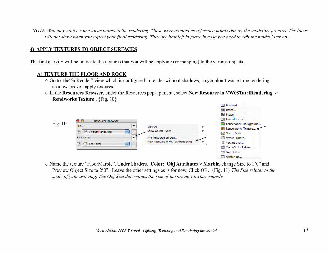
NOTE: You may notice some locus points in the rendering. These were created as reference points during the modeling process. The locus will not show when you export your final rendering. They are best left in place in case you need to edit the model later on.
4) APPLY TEXTURES TO OBJECT SURFACES The first activity will be to create the textures that you will be applying (or mapping) to the various objects.
A) TEXTURE THE FLOOR AND ROCK◇ Go to the“3dRender” view which is configured to render without shadows, so you don’t waste time rendering
shadows as you apply textures. ◇ In the Resources Browser, under the Resources pop-up menu, select New Resource in VW08TutrlRendering >
Rendworks Texture . {Fig. 10}
Fig. 10
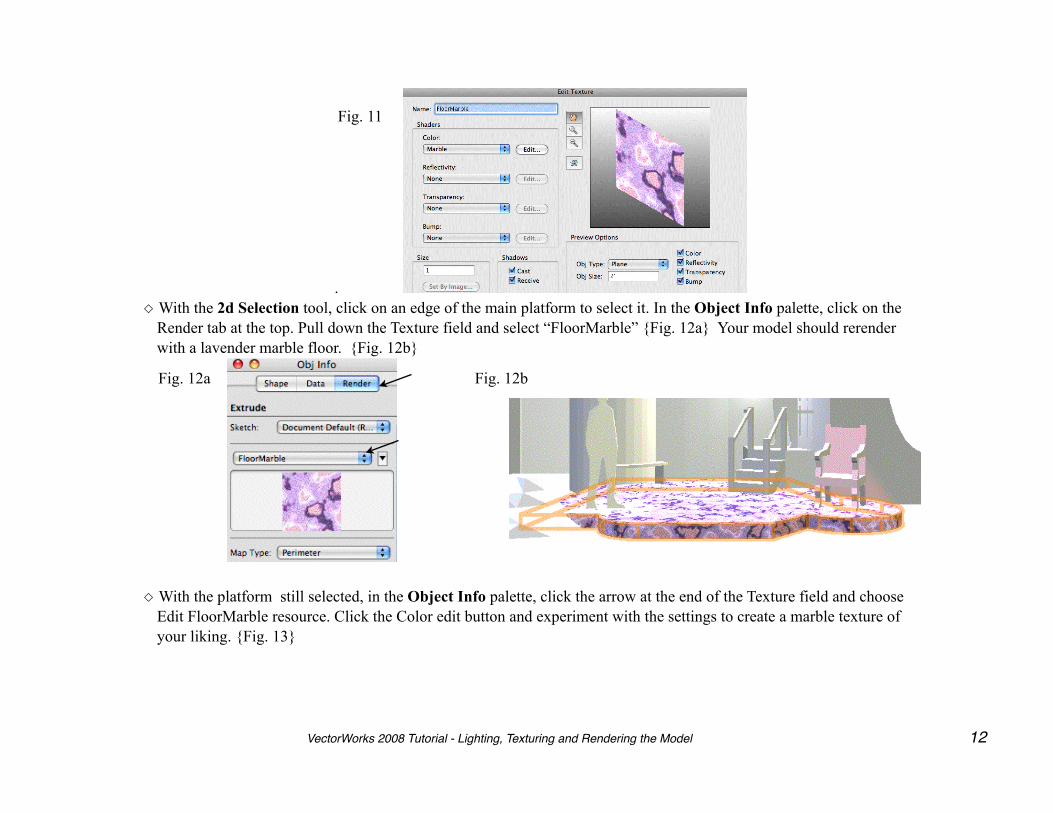
◇ Name the texture “FloorMarble”. Under Shaders, Color: Obj Attributes > Marble, change Size to 1’0” and
Preview Object Size to 2‘0”. Leave the other settings as is for now. Click OK. {Fig. 11} The Size relates to the scale of your drawing. The Obj Size determines the size of the preview texture sample.
VectorWorks 2008 Tutorial - Lighting, Texturing and Rendering the Model 11
.
Fig. 11
◇ With the 2d Selection tool, click on an edge of the main platform to select it. In the Object Info palette, click on the Render tab at the top. Pull down the Texture field and select “FloorMarble” {Fig. 12a} Your model should rerender with a lavender marble floor. {Fig. 12b}
Fig. 12a Fig. 12b
◇ With the platform still selected, in the Object Info palette, click the arrow at the end of the Texture field and choose Edit FloorMarble resource. Click the Color edit button and experiment with the settings to create a marble texture of your liking. {Fig. 13}
VectorWorks 2008 Tutorial - Lighting, Texturing and Rendering the Model 12
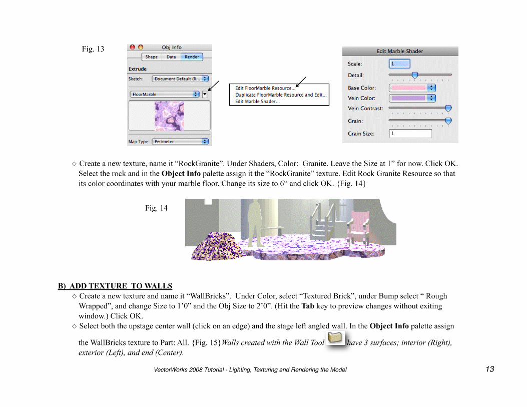
Fig. 13
◇ Create a new texture, name it “RockGranite”. Under Shaders, Color: Granite. Leave the Size at 1” for now. Click OK. Select the rock and in the Object Info palette assign it the “RockGranite” texture. Edit Rock Granite Resource so that its color coordinates with your marble floor. Change its size to 6“ and click OK. {Fig. 14}
Fig. 14
B) ADD TEXTURE TO WALLS◇ Create a new texture and name it “WallBricks”. Under Color, select “Textured Brick”, under Bump select “ Rough
Wrapped”, and change Size to 1’0” and the Obj Size to 2’0”. (Hit the Tab key to preview changes without exiting window.) Click OK.
◇ Select both the upstage center wall (click on an edge) and the stage left angled wall. In the Object Info palette assign
the WallBricks texture to Part: All. {Fig. 15}Walls created with the Wall Tool have 3 surfaces; interior (Right), exterior (Left), and end (Center).
VectorWorks 2008 Tutorial - Lighting, Texturing and Rendering the Model 13
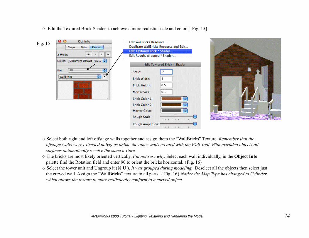
◇ Edit the Textured Brick Shader to achieve a more realistic scale and color. { Fig. 15}
Fig. 15
◇ Select both right and left offstage walls together and assign them the “WallBricks” Texture. Remember that the offstage walls were extruded polygons unlike the other walls created with the Wall Tool. With extruded objects all surfaces automatically receive the same texture.
◇ The bricks are most likely oriented vertically. I’m not sure why. Select each wall individually, in the Object Info palette find the Rotation field and enter 90 to orient the bricks horizontal. {Fig. 16}
◇ Select the tower unit and Ungroup it ( U ). It was grouped during modeling. Deselect all the objects then select just the curved wall. Assign the “WallBricks” texture to all parts. { Fig. 16} Notice the Map Type has changed to Cylinder which allows the texture to more realistically conform to a curved object.
VectorWorks 2008 Tutorial - Lighting, Texturing and Rendering the Model 14
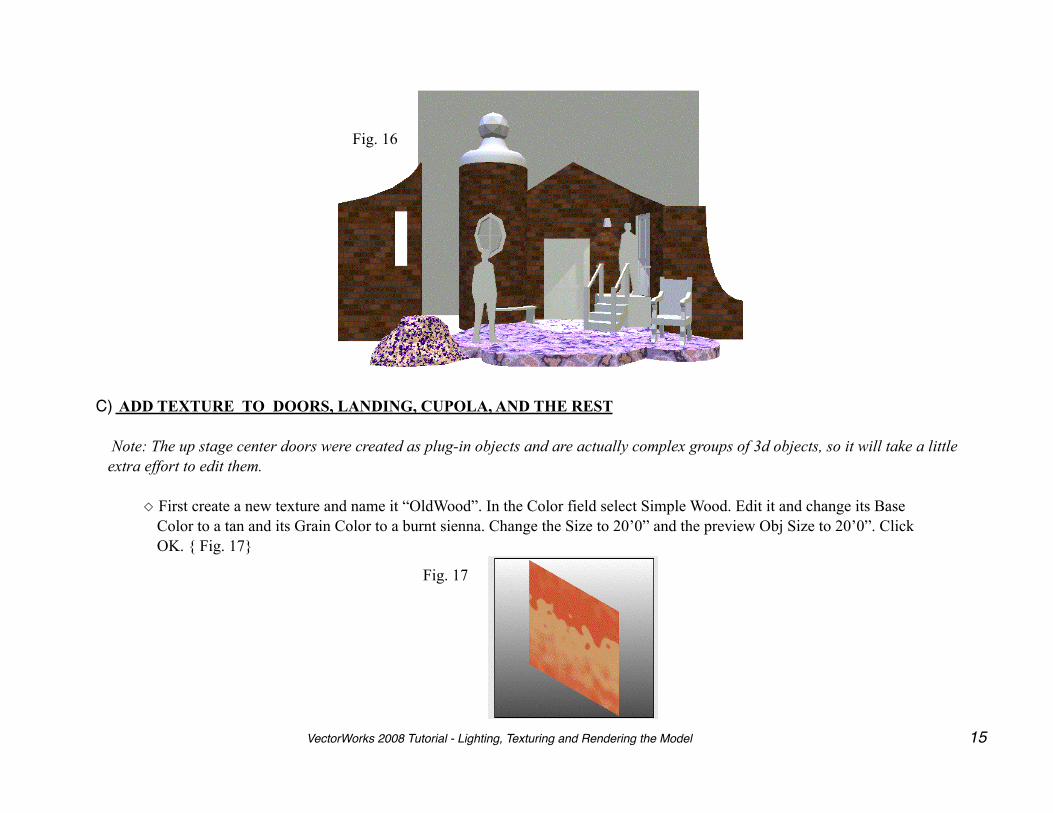
Fig. 16
C) ADD TEXTURE TO DOORS, LANDING, CUPOLA, AND THE REST
Note: The up stage center doors were created as plug-in objects and are actually complex groups of 3d objects, so it will take a little extra effort to edit them.
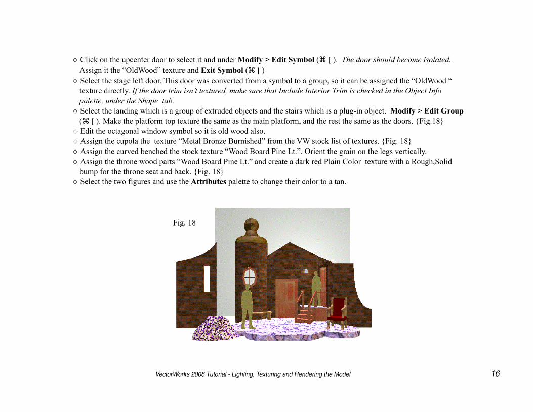
◇ First create a new texture and name it “OldWood”. In the Color field select Simple Wood. Edit it and change its Base Color to a tan and its Grain Color to a burnt sienna. Change the Size to 20’0” and the preview Obj Size to 20’0”. Click OK. { Fig. 17}
Fig. 17
VectorWorks 2008 Tutorial - Lighting, Texturing and Rendering the Model 15
◇ Click on the upcenter door to select it and under Modify > Edit Symbol ( [ ). The door should become isolated. Assign it the “OldWood” texture and Exit Symbol ( ] )
◇ Select the stage left door. This door was converted from a symbol to a group, so it can be assigned the “OldWood “ texture directly. If the door trim isn’t textured, make sure that Include Interior Trim is checked in the Object Info palette, under the Shape tab.
◇ Select the landing which is a group of extruded objects and the stairs which is a plug-in object. Modify > Edit Group ( [ ). Make the platform top texture the same as the main platform, and the rest the same as the doors. {Fig.18}
◇ Edit the octagonal window symbol so it is old wood also.◇ Assign the cupola the texture “Metal Bronze Burnished” from the VW stock list of textures. {Fig. 18}◇ Assign the curved benched the stock texture “Wood Board Pine Lt.”. Orient the grain on the legs vertically. ◇ Assign the throne wood parts “Wood Board Pine Lt.” and create a dark red Plain Color texture with a Rough,Solid
bump for the throne seat and back. {Fig. 18}◇ Select the two figures and use the Attributes palette to change their color to a tan.
Fig. 18
VectorWorks 2008 Tutorial - Lighting, Texturing and Rendering the Model 16
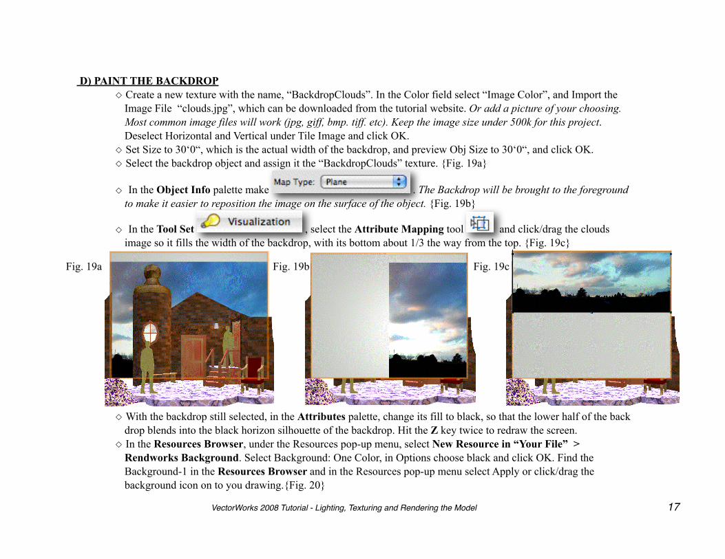
D) PAINT THE BACKDROP◇ Create a new texture with the name, “BackdropClouds”. In the Color field select “Image Color”, and Import the
Image File “clouds.jpg”, which can be downloaded from the tutorial website. Or add a picture of your choosing. Most common image files will work (jpg, giff, bmp. tiff. etc). Keep the image size under 500k for this project. Deselect Horizontal and Vertical under Tile Image and click OK.
◇ Set Size to 30‘0“, which is the actual width of the backdrop, and preview Obj Size to 30‘0“, and click OK. ◇ Select the backdrop object and assign it the “BackdropClouds” texture. {Fig. 19a}
◇ In the Object Info palette make . The Backdrop will be brought to the foreground to make it easier to reposition the image on the surface of the object. {Fig. 19b}
◇ In the Tool Set , select the Attribute Mapping tool and click/drag the clouds image so it fills the width of the backdrop, with its bottom about 1/3 the way from the top. {Fig. 19c}
Fig. 19a Fig. 19b Fig. 19c
◇ With the backdrop still selected, in the Attributes palette, change its fill to black, so that the lower half of the back drop blends into the black horizon silhouette of the backdrop. Hit the Z key twice to redraw the screen.
◇ In the Resources Browser, under the Resources pop-up menu, select New Resource in “Your File” > Rendworks Background. Select Background: One Color, in Options choose black and click OK. Find the Background-1 in the Resources Browser and in the Resources pop-up menu select Apply or click/drag the background icon on to you drawing.{Fig. 20}
VectorWorks 2008 Tutorial - Lighting, Texturing and Rendering the Model 17
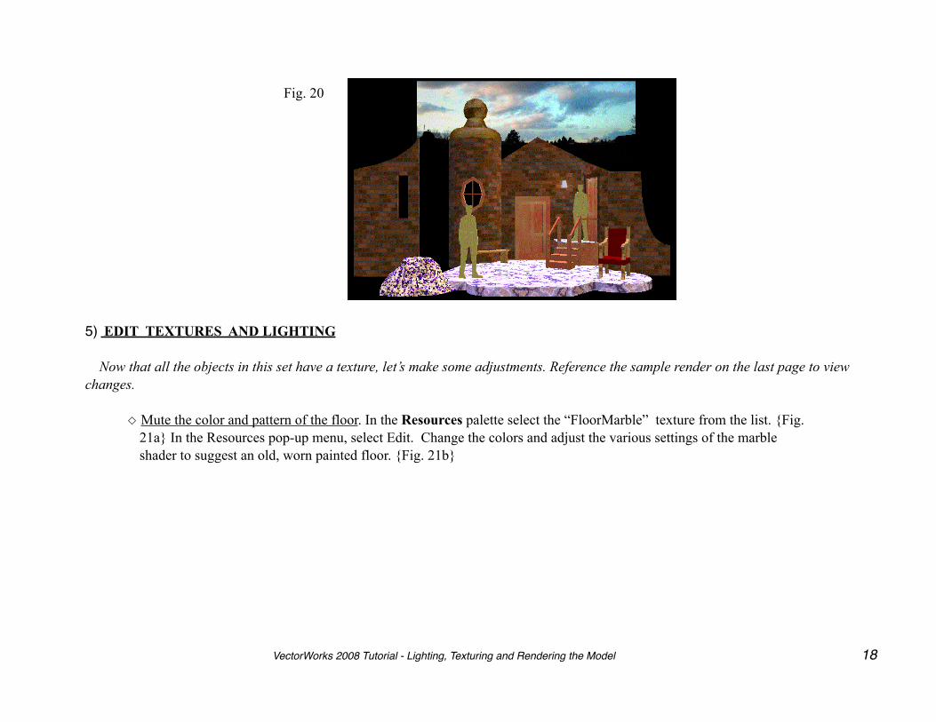
Fig. 20
5) EDIT TEXTURES AND LIGHTING
Now that all the objects in this set have a texture, let’s make some adjustments. Reference the sample render on the last page to view changes.
◇ Mute the color and pattern of the floor. In the Resources palette select the “FloorMarble” texture from the list. {Fig. 21a} In the Resources pop-up menu, select Edit. Change the colors and adjust the various settings of the marble shader to suggest an old, worn painted floor. {Fig. 21b}
VectorWorks 2008 Tutorial - Lighting, Texturing and Rendering the Model 18
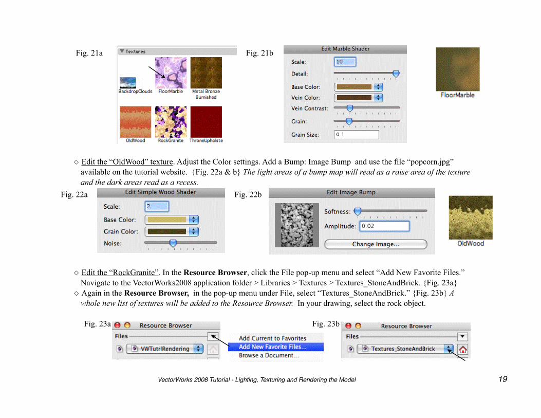
Fig. 21a Fig. 21b
◇ Edit the “OldWood” texture. Adjust the Color settings. Add a Bump: Image Bump and use the file “popcorn.jpg” available on the tutorial website. {Fig. 22a & b} The light areas of a bump map will read as a raise area of the texture and the dark areas read as a recess.
Fig. 22a Fig. 22b
◇ Edit the “RockGranite”. In the Resource Browser, click the File pop-up menu and select “Add New Favorite Files.” Navigate to the VectorWorks2008 application folder > Libraries > Textures > Textures_StoneAndBrick. {Fig. 23a}
◇ Again in the Resource Browser, in the pop-up menu under File, select “Textures_StoneAndBrick.” {Fig. 23b} A whole new list of textures will be added to the Resource Browser. In your drawing, select the rock object.
Fig. 23a Fig. 23b
VectorWorks 2008 Tutorial - Lighting, Texturing and Rendering the Model 19
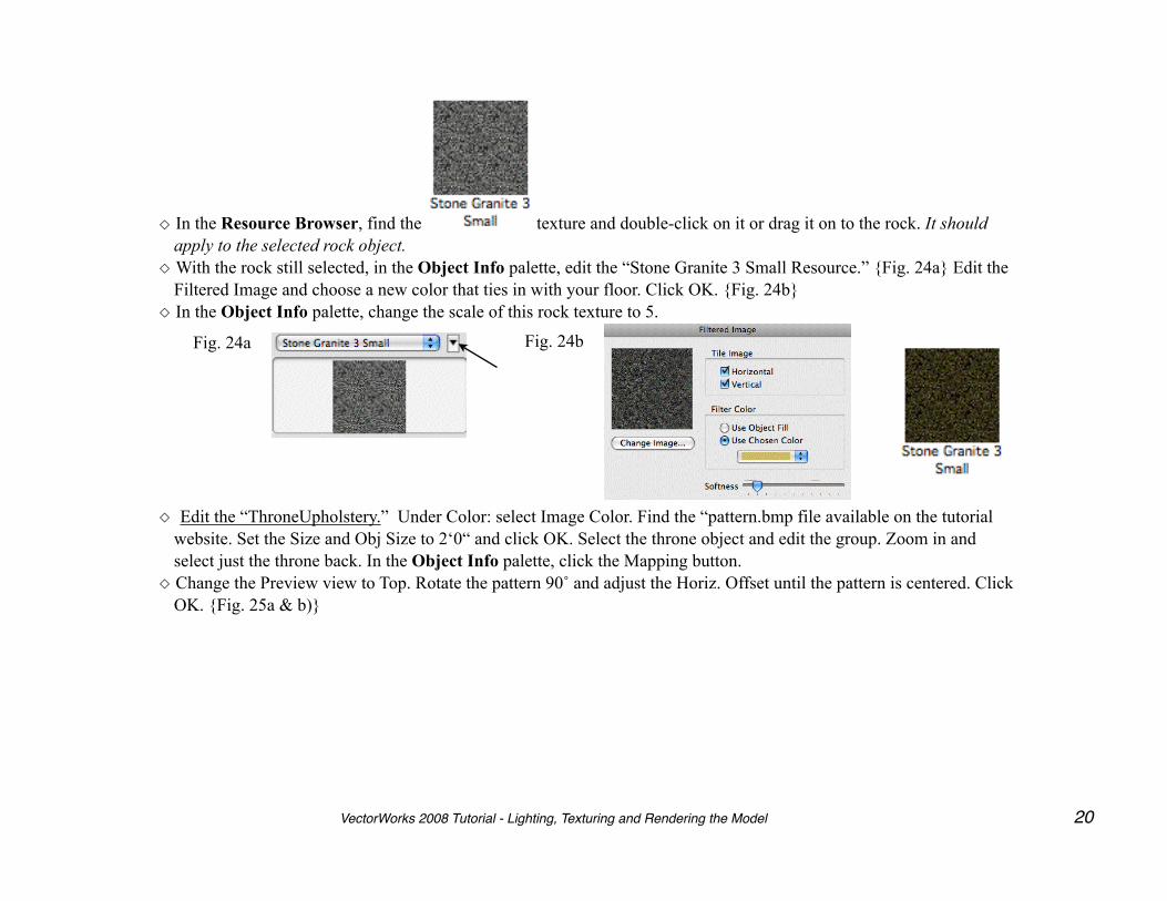
◇ In the Resource Browser, find the texture and double-click on it or drag it on to the rock. It should apply to the selected rock object.
◇ With the rock still selected, in the Object Info palette, edit the “Stone Granite 3 Small Resource.” {Fig. 24a} Edit the Filtered Image and choose a new color that ties in with your floor. Click OK. {Fig. 24b}
◇ In the Object Info palette, change the scale of this rock texture to 5.
Fig. 24a Fig. 24b
◇ Edit the “ThroneUpholstery.” Under Color: select Image Color. Find the “pattern.bmp file available on the tutorial website. Set the Size and Obj Size to 2‘0“ and click OK. Select the throne object and edit the group. Zoom in and select just the throne back. In the Object Info palette, click the Mapping button.
◇ Change the Preview view to Top. Rotate the pattern 90˚ and adjust the Horiz. Offset until the pattern is centered. Click OK. {Fig. 25a & b)}
VectorWorks 2008 Tutorial - Lighting, Texturing and Rendering the Model 20
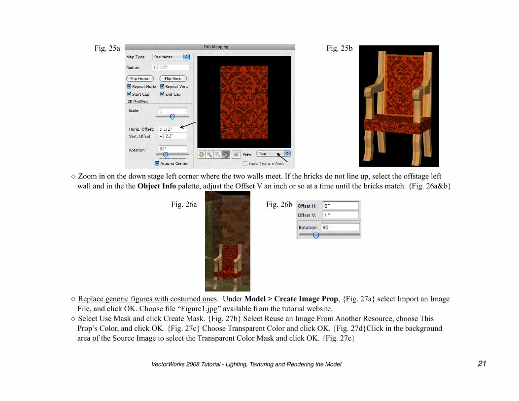
Fig. 25a Fig. 25b
◇ Zoom in on the down stage left corner where the two walls meet. If the bricks do not line up, select the offstage left wall and in the the Object Info palette, adjust the Offset V an inch or so at a time until the bricks match. {Fig. 26a&b}
Fig. 26a Fig. 26b
◇ Replace generic figures with costumed ones. Under Model > Create Image Prop, {Fig. 27a} select Import an Image File, and click OK. Choose file “Figure1.jpg” available from the tutorial website.
◇ Select Use Mask and click Create Mask. {Fig. 27b} Select Reuse an Image From Another Resource, choose This Prop’s Color, and click OK. {Fig. 27c} Choose Transparent Color and click OK. {Fig. 27d}Click in the background area of the Source Image to select the Transparent Color Mask and click OK. {Fig. 27e}
VectorWorks 2008 Tutorial - Lighting, Texturing and Rendering the Model 21
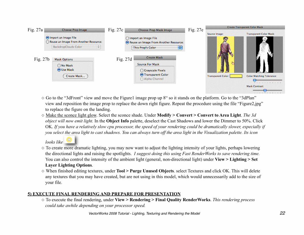
Fig. 27a
Fig. 27b
Fig. 27c
Fig. 27d
Fig. 27e
◇ Go to the “3dFront” view and move the Figure1 image prop up 8“ so it stands on the platform. Go to the “3dPlan” view and reposition the image prop to replace the down right figure. Repeat the procedure using the file “Figure2,jpg” to replace the figure on the landing.
◇ Make the sconce light glow. Select the sconce shade. Under Modify > Convert > Convert to Area Light. The 3d object will now emit light. In the Object Info palette, deselect the Cast Shadows and lower the Dimmer to 50%. Click OK. If you have a relatively slow cpu processor, the speed of your rendering could be dramatically slower, especially if you select the area light to cast shadows. You can always turn off the area light in the Visualization palette. Its icon
looks like .◇ To create more dramatic lighting, you may now want to adjust the lighting intensity of your lights, perhaps lowering
the directional lights and raising the spotlights. I suggest doing this using Fast RenderWorks to save rendering time. You can also control the intensity of the ambient light (general, non-directional light) under View > Lighting > Set Layer Lighting Options.
◇ When finished editing textures, under Tool > Purge Unused Objects. select Textures and click OK. This will delete any textures that you may have created, but are not using in this model, which would unnecessarily add to the size of your file.
5) EXECUTE FINAL RENDERING AND PREPARE FOR PRESENTATION◇ To execute the final rendering, under View > Rendering > Final Quality RenderWorks. This rendering process
could take awhile depending on your processor speed.
VectorWorks 2008 Tutorial - Lighting, Texturing and Rendering the Model 22
◇ In the Navigation palette, select the Sheet Layer button and double-click on the sheet to make it active. In the Pop-up menu select Duplicate. Edit the duplicate and rename it “ShtRender”. Check that the Page or Print Setup is correct for your printer. Up the DPI to 150.
◇ Change the title block to read Rendering Project and delete the scale.◇ Click on any object in your drawing to select the viewport. In the Object Info palette, change the Background Render
to “Final Quality Renderworks” and the RW Background to “Background-1”. Click the Update button. Again, this may take considerable time depending on the cpu speed of your computer.
Congratulations, you have completed the third and final tutorial in this series! There are many other 3D modeling and rendering applications available that allow you to articulate virtual space with greater verisimilitude and efficiency than VectorWorks. Some will import VectorWorks 3D models. Most will import 3D files in others format that VectorWorks exports (under File). The virtue of using RenderWorks along with VectorWorks is that the drafting, 3D modeling, lighting and rendering are contained all in one interface, keeping expense to a minimum.
VectorWorks 2008 Tutorial - Lighting, Texturing and Rendering the Model 23
VectorWorks 2008 Tutorial - Lighting, Texturing and Rendering the Model 24