lightning protection system (marqués de valdecilla hospital)
TRANSCRIPT
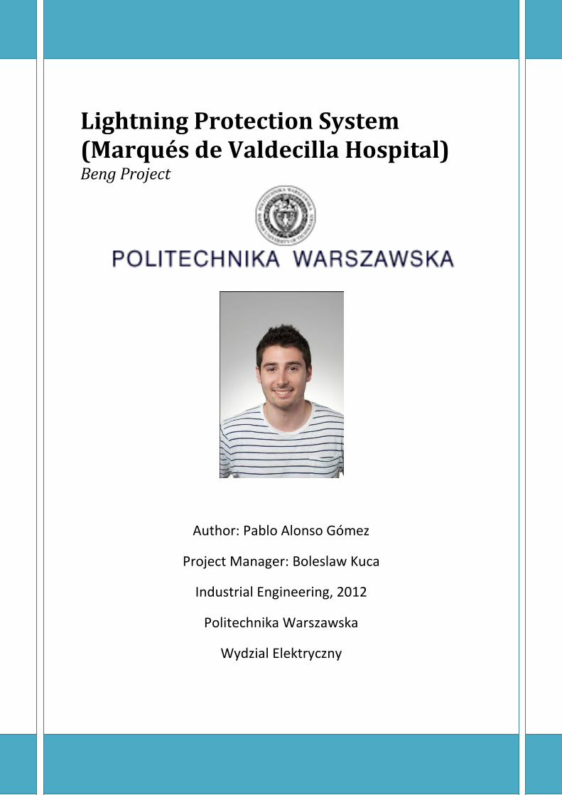
Lightning Protection System (Marqués de Valdecilla Hospital) Beng Project
Author: Pablo Alonso Gómez
Project Manager: Boleslaw Kuca
Industrial Engineering, 2012
Politechnika Warszawska
Wydzial Elektryczny

GENERAL INDEX
1. REPORT 1.1 Lightning, the phenomenon 1.1.1 Breakdown process 1.1.2 Lightning parameters 1.1.3 Current components
1.2 History 1.2.1 Mitology aspects 1.2.2 Evolution 1.2.3 Benjamin Franklin 1.2.4 XX Century
1.3 Introduction to protection methods 1.4 Risks management
1.4.1 Overview of risk analysis
1.5 Design methods 1.5.1 Mesh method 1.5.2 Protection angle method 1.5.3 The rolling sphere method – “Geometric-electrical model”
1.6 Lightning damage 1.6.1 What does lightning do to people? 1.6.2 Damage to human body 1.6.3 Most typical disorders associated with lightning strikes 1.6.4 Lightning disasters
2. SPECIFICATION 2.1 Weather 2.2 Marqués de Valdecilla Hospital
2.2.1 Risks 2.2.2

3. MEASUREMENT CONDITIONS
4. ECONOMIC ASPECTS
5. WEBGRAPHY

1.1 Lightning, the phenomenon
1.REPORT
Lightning is an atmospheric electric discharge in the form of a spark or flash, accompanied by thunder. It is originating in a charged cloud, usually associated and produced by cumulonimbus clouds (a towering vertical cloud that is very tall, dense, and involved in thunderstorms and other inclement weather), but also occurring during volcanic eruptions or in or can be caused by violent forest fires which generate sufficient dust to create a static charge.
There are some 16 million lightning storms in the world every year. Lightning causes ionization in the air through which it travels, leading to the formation of nitric and ultimately, nitric acid, of benefit to plant life below.
From this discharge of atmospheric electricity, a leader of a bolt of lightning can travel at speeds of 220 000 km/h and can reach temperatures approaching 30 000 ºC (54 000 ºF).
Figure 1. Lighting examples.
How lightning initially forms is still a matter of debate. Scientists have studied root causes ranging from atmospheric perturbations (wind, humidity, friction and atmospheric pressure) to the impact of solar wind and accumulation of charged solar particles. Ice inside a cloud is thought to be a key element in lightning development, and may cause a forcible separation of positive and negative charges within the cloud, thus assisting in the formation of lightning.

Due to various mechanisms in storm cloud formation, such as the rising and falling of air currents carrying moisture and ice particles, the storm cloud generates an electrical charge at its base. Charged regions in a thundercloud create conductive ionization channels through the atmosphere called “stepped leaders,” while an opposite electrical charge or “shadow” accumulates on the ground below.
It has now been known for a long time that thunder clouds are charged, and that the negative charge centre is located in the lower part of the cloud where the temperature is about – 5 C, and that the main positive charge centre is located several kilometers higher up, where the temperature is usually below – 20 C. In the majority of storm clouds, there is also a localized positively charged region near the base of the cloud where the temperature is 0 C.
The first stage of a lightning strike involves an initial discharge of low luminosity known as a downward leader. It forms at the cloud centre and moves down toward the ground in steps of several dozen meters at a time. (Fig. 2a) At the same time, the electric charge in the atmosphere at ground level increases as the downward leader gets closer. Any high point in the vicinity such as an electricity pylon or a lightning rod immediately gives rise to natural ionization in the form of a series of electrical discharges which are in blue color. This is the point effect or corona effect. As soon as the downward leader is close enough to the ground, the ionization due to the corona effect intensifies, especially near any high point, and eventually turns into an upward discharge: this discharge is the upward leader that develops toward the cloud. (Fig. 2b) When one of these upward leaders comes into contact with the downward leader, a conductive path is created allowing a powerful current to flow. This is lightning and is characterized by its bright flash and the deafening sound of thunder. (Fig. 2c) The lightning strike may in fact be made up of a number of successive return strokes, only a few hundredths of a second apart, all following the same highly ionized path.
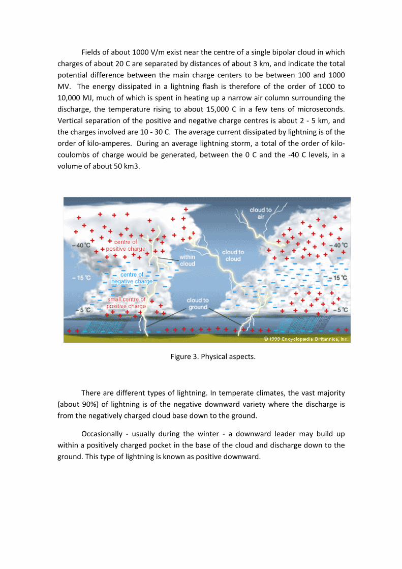
Fields of about 1000 V/m exist near the centre of a single bipolar cloud in which charges of about 20 C are separated by distances of about 3 km, and indicate the total potential difference between the main charge centers to be between 100 and 1000 MV. The energy dissipated in a lightning flash is therefore of the order of 1000 to 10,000 MJ, much of which is spent in heating up a narrow air column surrounding the discharge, the temperature rising to about 15,000 C in a few tens of microseconds. Vertical separation of the positive and negative charge centres is about 2 - 5 km, and the charges involved are 10 - 30 C. The average current dissipated by lightning is of the order of kilo-amperes. During an average lightning storm, a total of the order of kilo-coulombs of charge would be generated, between the 0 C and the -40 C levels, in a volume of about 50 km3.
Figure 3. Physical aspects.
There are different types of lightning. In temperate climates, the vast majority (about 90%) of lightning is of the negative downward variety where the discharge is from the negatively charged cloud base down to the ground.
Occasionally - usually during the winter - a downward leader may build up within a positively charged pocket in the base of the cloud and discharge down to the ground. This type of lightning is known as positive downward.
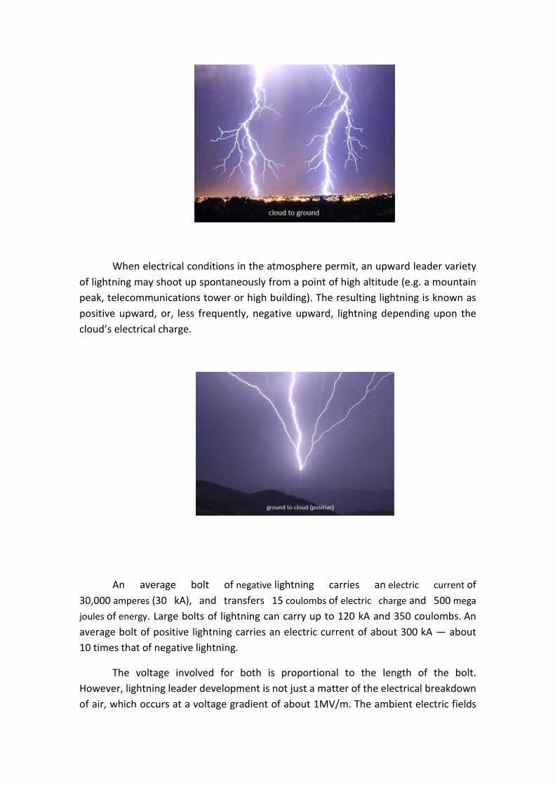
When electrical conditions in the atmosphere permit, an upward leader variety of lightning may shoot up spontaneously from a point of high altitude (e.g. a mountain peak, telecommunications tower or high building). The resulting lightning is known as positive upward, or, less frequently, negative upward, lightning depending upon the cloud’s electrical charge.
An average bolt of negative lightning carries an electric current of 30,000 amperes (30 kA), and transfers 15 coulombs of electric charge and 500 mega
joules of energy. Large bolts of lightning can carry up to 120 kA and 350 coulombs. An average bolt of positive lightning carries an electric current of about 300 kA — about 10 times that of negative lightning.
The voltage involved for both is proportional to the length of the bolt. However, lightning leader development is not just a matter of the electrical breakdown of air, which occurs at a voltage gradient of about 1MV/m. The ambient electric fields
required for lightning leader propagation can be one or two orders of magnitude (10−2) less than the electrical breakdown strength.
The potential (voltage) gradient inside a well-developed return-stroke channel is on the order of hundreds of volts per meter (V/m) due to intense channel ionization, resulting in a true power output on the order of one megawatt per meter (MW/m) for a vigorous return stroke current of 100 kA. The average peak power output of a single lightning stroke is about one trillion watts — one terawatt (1012 W), and the stroke lasts for about 30 millionths of a second — 30microseconds.
Lightning rapidly heats the air in its immediate vicinity to about 20,000 °C — about three times the temperature of the surface of the Sun. The sudden heating effect and the expansion of heated air give rise to a supersonic shock wave in the surrounding clear air. It is this shock wave, once it decays to an acoustic wave, which is heard as thunder.
Different locations have different potentials and currents for an average lightning strike.
NASA scientists have found that electromagnetic radiation created by lightning in clouds only a few miles high can create a safe zone in the Van Allen radiation belts that surround the earth. This zone, known as the "Van Allen Belt slot", may be a safe haven for satellites in middle Earth orbits (MEOs), protecting them from the Sun's intense radiation.
1.1.1 Breakdown Process
Under the influence of sufficiently strong fields, large water drops become elongated in the direction of the field and become unstable, and streamers develop at their ends with the onset of corona discharges. Drops of radius 2 mm develop streamers in fields exceeding a 9 kV/cm - much less than the 30 kV/cm required to initiate the breakdown of dry air. The high field need only be very localized, because a streamer starting from one drop may propagate itself from drop to drop under a much weaker field. When the electric field in the vicinity of one of the negative charge centers builds up to the critical value (about 10 kV/cm),an ionized channel (or streamer) is formed, which propagates from the cloud to earth with a velocity that might be as high as one-tenth the speed of light. Usually this streamer is extinguished when only a short distance from the cloud.
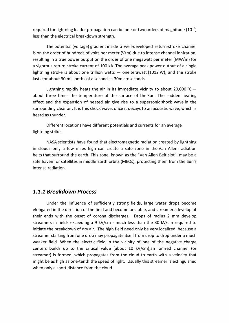
Forty micro-seconds or so after the first streamer, a second streamer occurs, closely following the path of the first, and propagating the ionized channel a little further before it is also spent. This process continues a number of times, each step increasing the channel length by 10 to 200 m. Because of the step like sequence in which this streamer travels to earth, this process is termed the stepped leader stroke.
When eventually the stepped leader has approached to within 15 to 50 m of the earth, the field intensity at earth is sufficient for an upward streamer to develop and bridge the remaining gap. A large neutralizing current flows along the ionized path, produced by the stepped leader, to neutralize the charge. This current flow is termed the return stroke and may carry currents as high as 200 kA, although the average current is about 20 kA.
The luminescence of the stepped leader decreases towards the cloud and in one instances it appears to vanish some distance below the cloud. This would suggest that the current is confined to the stepped leader itself. Following the first or main stroke and after about 40 ms, a second leader stroke propagates to earth in a continuous and rapid manner and again a return stroke follows. This second and subsequent leader strokes which travel along the already energized channel are termed dart leaders.
What appears as a single flash of lightning usually consist of a number of successive strokes, following the same track in space, at intervals of a few hundredths of a second. The average number of strokes in a multiple stroke is four, but as many as 40 have been reported. The time interval between strokes ranges from 20 to 700 ms, but is most frequently 40-50ms. The average duration of a complete flash being about 250ms.

The approximate time durations of the various components of a lightning stroke are summarized as follows.
Stepped leader = 10 ms
Return stroke = 40 µs
Period between strokes = 40 ms
Duration of dart leader = 1 ms
For the purpose of surge calculations, it is only the heavy current flow during the return stroke that is of importance. During this period it has been found that the waveform can be represented by a double exponential of the form
)
with wave front times of 0.5 – 10 µs, and wave tail times of 30 – 200 µs.
The standard voltage waveform used in high voltage testing has a 1.2/50 µs waveform to take into account the most severe conditions. For the standard waveform, the coefficients α and β in the double exponential have values of α= 1.426 x 10^4 s-1, and β= 4.877 x 10^6 s-1
1.1.2 Lightning parameters
Nowadays the electrical activity measured in tall objects has been widely characterized, but the collected data of lightning rods installed in buildings do not amount to enough to obtain reliable statistics. The measures stored at relatively few points are not representative of the different types of installations. Furthermore, the protection model applied for lightning air terminal installations is based on theoretical models.
The technical committee TC 81 “Lightning Protection” of the International Electrotechnical Commission IEC was established in Stockholm in June 1980 the scope to prepare international standards and guides for lightning protection for structures and buildings, as well for persons, installations, services and contents. Meanwhile, the results of TC 81 are published in the international standard series IEC 62305.
TC 81 decided as one of the first steps to define the lightning threat as a common basis to any protection measures. The lightning threat is mainly derived from the measurements of Berger performed at two 70m towers on the Mountain San Salvatore in Switzerland. Up to now, the results published in CIGRE Electra in 1975 and

1980 represent the most complete data base of lightning currents and their relevant parameters.
Relevant current parameters for the lightning protection
The current is the primary source for all thermal and mechanical damages caused by lightning. Besides that, the rate-of-rise of the lightning currents may induce overvoltages in electric and electronic systems or devices. The lightning threat is associated with the following current parameters:
- Current peak: imax - Charge:
- Specific energy:
- Maximum current derivative:
The peak current is important for the design of the earth termination system. When the lightning current enters the earth, the current flowing through the earthing resistance produces a voltage drop. The peak current determines the maximum value of this voltage drop. This voltage drop may lead to side flashes when conductive services lines enter a building unbounded.
The charge Q is responsible for the melting effects at the attachment points of the lightning channel. The energy input at the arc root is given by the anode/cathode voltage drop multiplied by the charge Q.
The specific energy W/R is responsible for mechanical forces and for the heating effects, when the lightning current flows through metallic conductors.
Electronic devices are normally connected to different electrical services as the mains supply and the data link. Depending on the line routing inside a structure, large loops may be formed by these lines. The maximum current steepness determines the maximum of the magnetically induced voltages into open loops.
1.1.3 Current components
Lightning is a natural phenomenon where, for the purpose of analysis and design, a statistical approach is taken. Data from International Council of Large Electrical Systems (CIGRE) indicates that:
• 5% of first, negative lightning strokes exceed 90 kA (average is 33 kA)
• 5% of positive lightning strokes exceed 250 kA (average is 34 kA)

• 5% of negative subsequent strokes exceed a rate of current rise of 161 kA/μs
The measurements revealed that the current parameters of the upward
lightning do not exceed the current parameters of the downward lightning. Because no additional threat has to be taken into account for the upward lightning, the current components codified in the IEC 62305-1 are exclusively based on the currents of the downward lightning. In order to represent the threat of the lightning currents, the following basic current components are fixed in the standard IEC 62305-1:
- First short stroke current - Subsequent short stroke current - Long stroke current
The first short stroke current takes into account the threat of the first return strokes of downward lightning. The threat of the first return strokes mainly originates from the positive lightning higher current peaks imax higher impulse charge Qi and higher specific energy W/R compared to the negative lightning. According to the measurements of Berger, a relatively strong correlation exists between these three parameters.
In the IEC 62305 series, four lightning protection levels LPL are introduced to take into account the different safety requirements of various buildings. For instance, a dwelling house requires a lower safety level than a plant handling explosive materials.
For a reliable protection against the thermal and mechanical effects of lightning as well as induced over-voltage the current parameters at the upper end of the statistical lightning current distributions have to be taken into account. It was the intention of TC 81 that the parameters fixed for LPL I shall not be exceeded in naturally occurring lightning with a probability of about 99%. For the LPL II the parameters of LPL I are reduced to 75% and for LPL III and LPL IV to 50% of LPL I. The reduction follows a linear relationship for a peak current, impulse charge and current steepness, but a quadratic one for the specific energy.
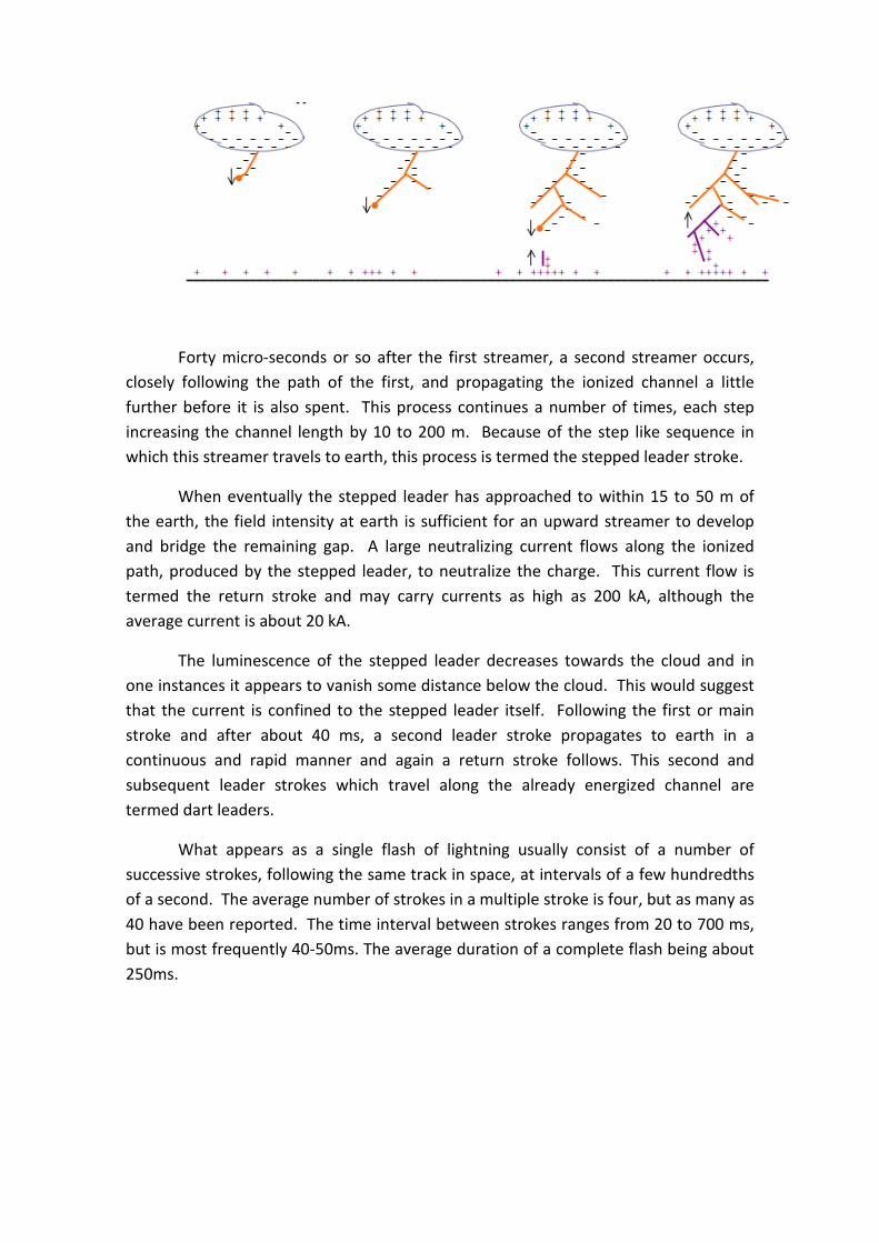
The following table indicates for these lightning protection levels the maximum current expected and the probability that this may be exceeded. The standard ensures that air-termination, conductor and earth termination size are sufficient to withstand the expected maximum current.
LPL I LPL II LPL III LPL IV Maximum peak current (kA 10/350 μs) 200 150 100 100 Probability current is greater (%) 1 2 3 3
The following table shows the relations between lightning protection level, interception criterion, final striking distance and minimum peak value of current:

1.2 History
1.2.1 Mythology aspects (The electric magic)
There was another earlier time when lightning was the magic fire from the sky which man captured and used to keep warm at night. It kept the savage animals away. As primitive man sought answers about the natural world, lightning became a part of his superstitions, his myths and his early religions.
- Early Greeks believed that lightning was a weapon of Zeus. Thunderbolts were invented by Athena, the goddess of wisdom. Since lightning was a manifestation of the gods, any spot struck by lightning was regarded as sacred. Greek and Roman temples often were erected at these sites, where the gods were worshipped in an attempt to appease them.
- The Moslems also attributed lightning and thunder to their god. The Koran says, "He is who showed you lightning and launches the thunderbolts."
- Scandinavian mythology alludes to Thor, the thunderer, who was the foe of all demons. Thor tossed lightning bolts at his enemies. Thor also gave us Thurs-day.
- In the pantheistic Hindu religion, Indra was the god of heaven, lightning, rain, storms and thunder. The Maruts used the thunderbolts as weapons.
- Umpundulo is the lightning bird-god of the Bantu tribesmen in Africa. Even today their medicine men go out in storms and bid the lightning to strike far away.
- The Navajo Indians hold that lightning has great power in their healing rituals. Sand paintings show the lightning bolt as a wink in the Thunderbird's eye. Lightning is associated with wind, rain and crop growth.
- As late as the early 1800s in Russia, when rain was wanted, three men climbed a tree. One would knock two firebrands together; the sparks imitating lightning. Another one would pour water over twigs, imitating rain. A third would bang on a kettle to attract the thunder. And throughout early Europe, church bell ringers would make as much noise as possible, hoping to scare away the storms from these holy dwellings which were struck frequently by lightning.
- Even Santa Klaus gets into the act with his reindeer Donner (thunder) and Blitzen (lightning).

1.2.2 Evolution
Early superstitions were observed as “Cause and Effect”, which now has been fancified as science. The first attempt at a scientific explanation of lightning was undertake by Socrates, who claimed “it was not Zeus up there, but a vortex of air”.
Ghengis Kahn forbade his subjects from washing garments or bathing in running water during a storm. Thales, the Greek philosopher, in 600 BC, rubbed a piece of amber with a dry cloth and noted that it would then attract feathers and straw. But he didn't link the phenomenon to lightning.
In ancient Rome, members of the College of Augurs divined the will of the gods by observing the southern sky for lightning, birds, and shooting stars. A lightning bolt passing from left to right was a favorable omen; a lightning bolt passing from right to left was a sign that Jove did not approve of current political events. Furthermore, whenever the augurs reported any sign of lightning, the magistrates of Rome were required to cancel all public assemblies on the following day. The augurs' reports became politically useful to postpone unwanted meetings, delay the passage of laws, or prevent the election of certain magistrates by popular assemblies.
Meanwhile Ghengis Kahn took a much more practical approach to lightning, forbidding his subjects from washing garments or bathing in running water during a storm.
By the late 1500s, European scientists were undertaking the first experiments to duplicate it on a laboratory scale. William Gilbert, court healer to Queen Elizabeth used amber to duplicate the earlier experiments. He named this "via electrica", after electra which is Greek for amber. He didn't know it, but he was demonstrating static electricity.
During the sixteenth century various machines for generating static electricity were invented...the Leyden jar was like a thermos bottle which stored volts. Friction machines could charge the jars and electricity could be carried around and demonstrated. "Electric magic" was in great demand at the royal courts of Europe as entertainment. The parlor tricks amused and fascinated people.
In medieval Europe and England it was general practice to ring church bells violently during thunderstorms in an effort to keep the lightning from striking the tall church spire. Some felt the clamor of the bells dispersed evil spirits that sought to destroy the church with fire; others claimed that the noise of the bells disrupted the lightning strokes. (The second reason explains the common inscription on medieval bells: "Fulgura Frango" which means "I break up the lightning flashes"). This didn't stop lightning from striking 386 French church towers during the years from 1753 to 1786. Even worse, during the same period lightning running down the bell ropes killed 103 French bell ringers.
The 17th Century saw rapid advances in many areas of science and mathematics, usually involving Sir Isaac Newton. He proposed that basic mathematical laws were the foundation for understanding the forces of nature, but with "electric magic" there was insufficient experimental investigation to explain its behavior.
In 1746, however, a Scot called Dr. Spence came to Philadelphia. He there demonstrated some "electric magic" to an audience which included the local postmaster. That man was Benjamin Franklin. Franklin was curiosity personified. At age eight he left the Boston Grammar School, ending his formal studies. He was endowed with a strong sense of investigation and self-discipline. He learned and studied things all his life. He invented the bifocal glasses and the Franklin stove. An expert swimmer, a vegetarian, multi-lingual, and a word-smith publisher, his Poor Richard's Almanac was selling 10,000 copies a year in the colonies…
1.2.3 Benjamin Franklin
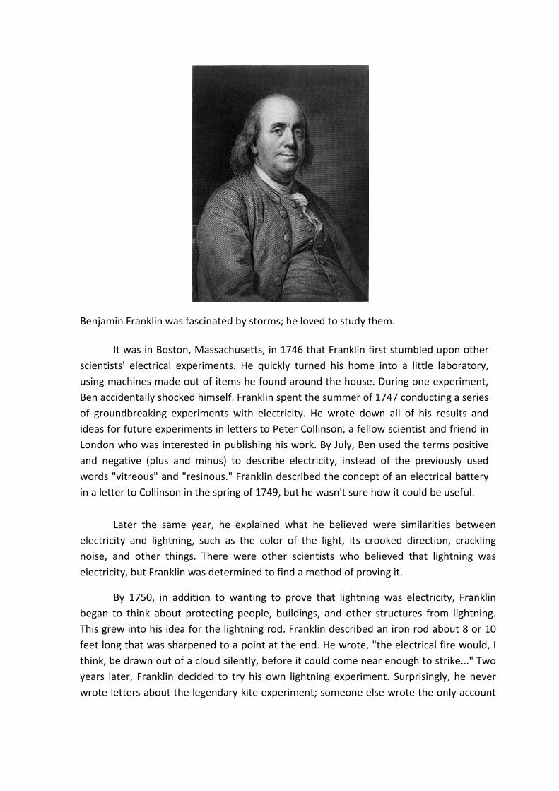
Benjamin Franklin (January 17, 1706 – April 17, 1790) was one of the Founding Fathers of the United States. A noted polymath, Franklin was a leading author, printer, political theorist, politician, postmaster, scientist, musician, inventor, satirist, civic activist, statesman, and diplomat. As a scientist, he was a major figure in the American Enlightenment and the history of physics for his discoveries and theories regarding electricity. He invented the lightning rod, bifocals, the Franklin stove, a carriage odometer, and the glass 'armonica'.
Benjamin Franklin was fascinated by storms; he loved to study them.
It was in Boston, Massachusetts, in 1746 that Franklin first stumbled upon other scientists' electrical experiments. He quickly turned his home into a little laboratory, using machines made out of items he found around the house. During one experiment, Ben accidentally shocked himself. Franklin spent the summer of 1747 conducting a series of groundbreaking experiments with electricity. He wrote down all of his results and ideas for future experiments in letters to Peter Collinson, a fellow scientist and friend in London who was interested in publishing his work. By July, Ben used the terms positive and negative (plus and minus) to describe electricity, instead of the previously used words "vitreous" and "resinous." Franklin described the concept of an electrical battery in a letter to Collinson in the spring of 1749, but he wasn't sure how it could be useful.
Later the same year, he explained what he believed were similarities between electricity and lightning, such as the color of the light, its crooked direction, crackling noise, and other things. There were other scientists who believed that lightning was electricity, but Franklin was determined to find a method of proving it.
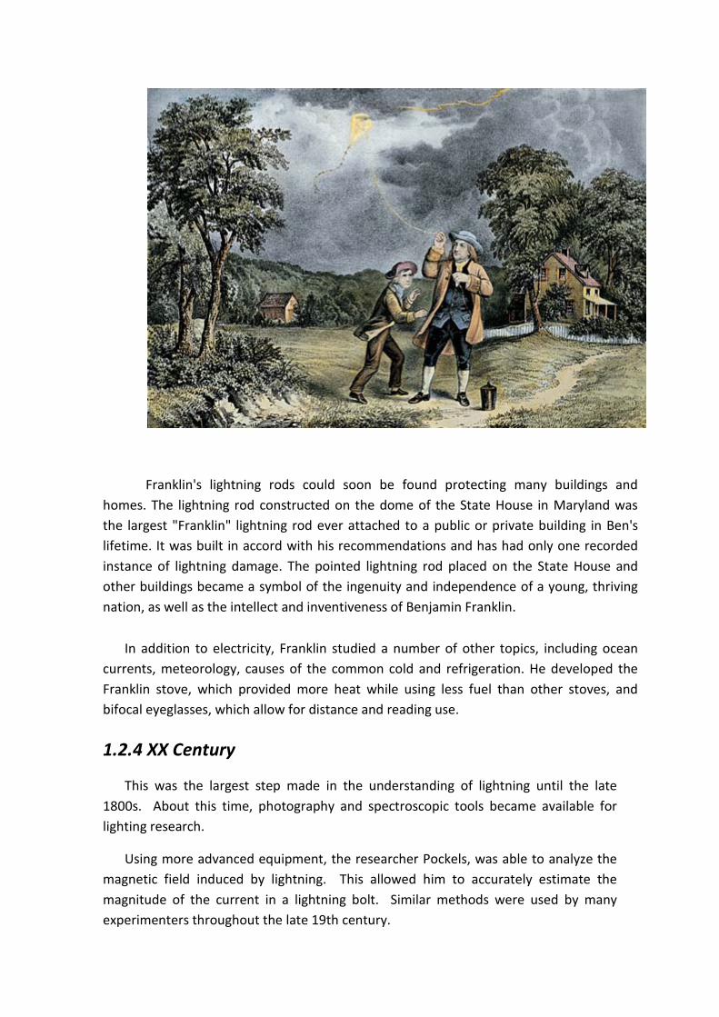
By 1750, in addition to wanting to prove that lightning was electricity, Franklin began to think about protecting people, buildings, and other structures from lightning. This grew into his idea for the lightning rod. Franklin described an iron rod about 8 or 10 feet long that was sharpened to a point at the end. He wrote, "the electrical fire would, I think, be drawn out of a cloud silently, before it could come near enough to strike..." Two years later, Franklin decided to try his own lightning experiment. Surprisingly, he never wrote letters about the legendary kite experiment; someone else wrote the only account
15 years after it took place.
In June of 1752, Franklin was in Philadelphia, waiting for the steeple on top of Christ Church to be completed for his experiment (the steeple would act as the "lightning rod"). He grew impatient, and decided that a kite would be able to get close to the storm clouds just as well. Ben needed to figure out what he would use to attract an electrical charge; he decided on a metal key, and attached it to the kite. Then he tied the kite string to an insulating silk ribbon for the knuckles of his hand. Even though this was a very dangerous experiment, some people believe that Ben wasn't injured because he didn't conduct his test during the worst part of the storm. At the first sign of the key receiving an electrical charge from the air, Franklin knew that lightning was a form of electricity. His 21-year-old son William was the only witness to the event.
Two years before the kite and key experiment, Ben had observed that a sharp iron needle would conduct electricity away from a charged metal sphere. He first theorized that lightning might be preventable by using an elevated iron rod connected to earth to empty static from a cloud.
Franklin began to advocate lightning rods that had sharp points. His English colleagues favored blunt-tipped lightning rods, reasoning that sharp ones attracted lightning and increased the risk of strikes; they thought blunt rods were less likely to be struck. King George III had his palace equipped with a blunt lightning rod. When it came time to equip the colonies' buildings with lightning rods, the decision became a political statement. The favored pointed lightning rod expressed support for Franklin's theories of protecting public buildings and the rejection of theories supported by the King. The English thought this was just another way for the flourishing colonies to be disobedient to them.
Franklin's lightning rods could soon be found protecting many buildings and homes. The lightning rod constructed on the dome of the State House in Maryland was the largest "Franklin" lightning rod ever attached to a public or private building in Ben's lifetime. It was built in accord with his recommendations and has had only one recorded instance of lightning damage. The pointed lightning rod placed on the State House and other buildings became a symbol of the ingenuity and independence of a young, thriving nation, as well as the intellect and inventiveness of Benjamin Franklin.
In addition to electricity, Franklin studied a number of other topics, including ocean currents, meteorology, causes of the common cold and refrigeration. He developed the Franklin stove, which provided more heat while using less fuel than other stoves, and bifocal eyeglasses, which allow for distance and reading use.
1.2.4 XX Century
This was the largest step made in the understanding of lightning until the late 1800s. About this time, photography and spectroscopic tools became available for lighting research.
Using more advanced equipment, the researcher Pockels, was able to analyze the magnetic field induced by lightning. This allowed him to accurately estimate the magnitude of the current in a lightning bolt. Similar methods were used by many experimenters throughout the late 19th century.

Although experiments from the time of Benjamin Franklin showed that lightning was a discharge of static electricity, there was little improvement in theoretical understanding of lightning (in particular how it was generated) for more than 150 years. The impetus for new research came from the field of power engineering: as power transmission lines came into service, engineers needed to know much more about lightning in order to adequately protect lines and equipment. In 1900, Nikola Tesla generated artificial lightning by using a large Tesla coil, enabling the generation of enormously high voltages sufficient to create lightning.
Lightning research was heavily increased in the 1960s. This increase was caused by several things. First of all, lightning posed a great threat to aerospace vehicles and solid state electronic used in computers and other devices (which came into play in the 1960s). Secondly, the research was made easier and better by improved measurement and observational capabilities created by technology.
Recently some scientists have concluded that lightning may have played a part in the evolution of living organisms. Nobel Prize winning chemist Harold Urey proposed that the earth's early atmosphere consisted of ammonia, hydrogen, methane, and water vapor. One of his students, Stanley Miller, used an electric spark to duplicate lightning and introduced it into the chemical brew. He was careful to exclude any living organisms from the experiment. At the end of a week, he examined the mixture and found it contained newly-formed amino acids, the very building blocks of protein. Did lightning play a role in creating life itself? Science now is pushing the envelope of lightning's secrets. More has been learned about this transient phenomenon in the

past 3-4 years than in the preceding two hundred forty four years since Franklin's "kites and keys" experiments.
1.3 Introduction to protection methods
The design of a lightning protection system needs to:
• Intercept lightning flash (i.e. create a preferred point of strike)
• Conduct the lightning current to earth
• Dissipate current into the earth
• Create an equipotential bond to prevent hazardous potential differences between LPS, structure and internal elements/circuits.
In achieving this the lightning protection system must:
• Not cause thermal or mechanical damage to the structure
• Not cause sparking which may cause fire or explosion
• Limit step and touch voltages to control the risk of injury to occupants
• Limit damage to internal electrical and electronic systems
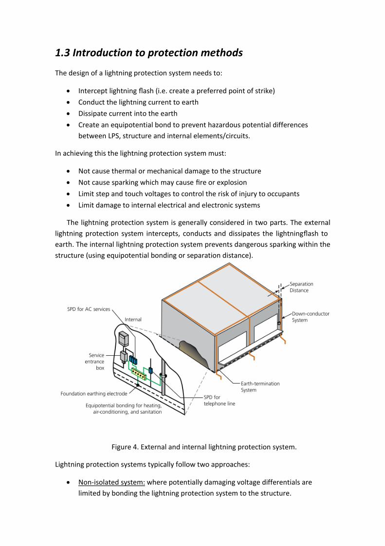
The lightning protection system is generally considered in two parts. The external lightning protection system intercepts, conducts and dissipates the lightning flash to earth. The internal lightning protection system prevents dangerous sparking within the structure (using equipotential bonding or separation distance).
Figure 4. External and internal lightning protection system.
Lightning protection systems typically follow two approaches:
• Non-isolated system: where potentially damaging voltage differentials are limited by bonding the lightning protection system to the structure.

• Isolated system:
where the lightning protection system is isolated from the structure by a specified separation distance. This distance should be sufficient that energy is contained on the LPS and does not spark to the structure. Isolated systems are well suited to structures with combustible materials such as thatched roofs, or telecommunication sites that want to avoid lightning currents being conducted on masts and antenna bodies.
The standard provides simple geometric forms of design which are comprised of cost, effectiveness and simplicity in design. The design methods are:
• Mesh method
• Rolling sphere method (RSM)
• Protection angle method (PAM)
These methods are used to determine the optimum location of the air-terminations and the resulting down-conductor and earthing requirements.
A risk assessment is generally undertaken to determine the level of risk for a specific structure, in order to make a comparison with a pre-determined value of “acceptable risk”. Protection measures, at an appropriate lightning protection level (LPL), are then implemented to reduce the risk to or below the acceptable risk. The lightning protection level determines the spacing of the mesh, radius of rolling sphere, protective angle, etc.
It should be noted that while lightning protection is typically implemented as a bonded network of air-terminals and downconductors, other methods are permitted:
• To limit touch and step potential risks: o Insulation of exposed conductive parts

o Physical restriction and warning signs
• To limit physical damage: o Fire proofing, fire extinguishing systems, protected escape routes.

1.4. Risk management
IEC 62305-2 provides a lightning risk management procedure that provides a tolerable limit of risk, methods to calculate the actual risk, and then evaluates the protection methods required to reduce the actual risk to be equal or lower than the tolerable risk. The main outcome from this risk assessment is to determine if lightning protection is required and if so, to select the appropriate lightning class. The lightning class determines the minimum lightning protection level (LPL) that is used within the lightning protection design.
Lightning protection can be installed even when the risk management process may indicate that it is not required. A greater level of protection than that required may also be selected.
A full manual analysis of all risks can take tens of hours to complete. Therefore for most situations a reduced analysis is conducted, preferably with an electronic tool. For this purpose, the IEC standard comes with software, and additional third-party software is also available.
For complex or high risk structures/situations, a more detailed analysis should be considered using the full standard. This would include, but is not limited to:
• Locations with hazardous or explosive materials
• Hospitals or other structures where failure of internal systems may cause a life hazard
1.4.1. Overview of risk analysis
Conceptually the risk analysis follows the general process of:
1) Identifying the structure to be protected and its environment 2) Evaluating each loss type and associated risk (R1 to R3) 3) Comparing R1 to R3 to the appropriate tolerable risk RT to determine if
protection is needed 4) Evaluating protection options so R1 to R3 ≤ RT
Note that separate RT figures exist for risk of losses R1 to R3. Lightning protection is required such that R1, R2 & R3 are all equal or lower than the respective tolerable risk (RT).
Lightning protection may also be justified upon the economic risk R4 and the respective economic benefit. A separate procedure in IEC 62305-2 is followed for this analysis.

Each of the following risks are broken down into individual risk components (sub categories), which are then evaluated with regard to direct and indirect lightning effects upon the structure and on the services. This requires the computation of the number of dangerous events, which is related to the structure size and lightning flash density.
Sources of damage, type of damage, type of loss and risk of loss
It is important to understand the sources of damage, types of damage and types of losses as the procedure to assess the risk evaluates various combinations considering structure, contents, services and environment with the source and type of damage.
The sources of damage are (figure 5):
• S1: Lightning flash to the structure
• S2: Lightning flash near the structure
• S3: Lightning flash to the services
• S4: Lightning flash near to the services
Figure 5. Sources of damage
With the possible sources of damage due to lightning flash defined, three possible types of damage are identified:
• D1 – Injury of living beings (humans and animals) due to touch and step potential

• D2 – Physical damage (fire, explosion, mechanical destruction, chemical release)
• D3 – Failure of internal electrical/electronic systems due to lightning electromagnetic impulse
With each type of damage, four types of losses are identi fied:
• L1 – Loss of human life
• L2 – Loss of essential service to the public
• L3 – Loss of cultural heritage
• L4 – Economic loss (structure and its contents, service and loss of activity)
Care is required with the term “services”, as it is dependant upon its context within the standard. This may refer to the physical services connected to the building (water, power, gas, fuel or data/telecommunications), or services provided to the public (e.g. information services). The scope of services to the public includes any type of supplier who, due to lightning damage, can not provide their goods or “service” to the public.
Table 1 summarizes the types of damage and types of loss for each of the four sources of damage [from IEC 62305-1 Table 3]. For each of the first three types of losses (L1, L2 & L3), the procedure of IEC 62305-2 evaluates the risk of these respective losses (R1, R2 & R3) and compares them to tolerable levels. For Loss L4, the economic cost of the loss, with and without lightning protection, is compared to the cost of the protection measures.

Table 1. Damages and losses in a structure for different sources
Risk management procedure & tolerable risk
For each of the losses L1 to L3, the risk of each loss is determined (R1 to 3). The risk of each loss is then compared to a tolerable risk:
• If the calculated risk is equal or less than the respective tolerable risk (RT), then lightning protection is not required
• If the calculated risk is higher than the tolerable risk then protection is required. Protective measures should be evaluated to reduce the calculated risk to be equal or less than the tolerable risk
Table 2 provides the tolerable risks as provided by IEC standard. The tolerable risk is expressed in the form of number of events per year and is given in engineering units (e.g. 10-x). Table 2 also expresses these in the format of x in y events (per year).
Table 2. Tolerable risk RT

1.5 Design methods:
The rolling sphere method, mesh method and protection angle method are used to determine the required positioning of the lightning protection air-terminations. While there are limits on the application of the protection angle and mesh methods, generally the standard considers the three methods as equivalent.
The rolling sphere method is recommended as the most universal method, while the mesh method is more suitable for the protection of flat surfaces. The protection angle method can only be used with limited vertical distances. Different design methods can be applied to different regions of a single lightning protection system, provided the zones afforded by each method overlap to protect the entire structure.
Any of these methods can be used to determine placement of the air-terminations. Permitted air-terminations are:
• Rods (including masts and free standing masts)
• Meshed conductors (on building surface or elevated)
• Catenary wires
• Natural components
Figure 6. Air-Terminations.
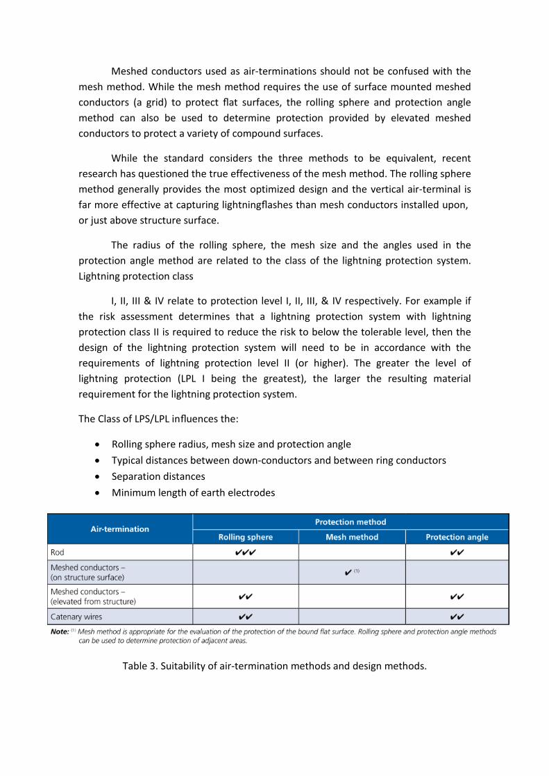
Meshed conductors used as air-terminations should not be confused with the mesh method. While the mesh method requires the use of surface mounted meshed conductors (a grid) to protect flat surfaces, the rolling sphere and protection angle method can also be used to determine protection provided by elevated meshed conductors to protect a variety of compound surfaces.
While the standard considers the three methods to be equivalent, recent research has questioned the true effectiveness of the mesh method. The rolling sphere method generally provides the most optimized design and the vertical air-terminal is far more effective at capturing lightning flashes than mesh conductors installed upon, or just above structure surface.
The radius of the rolling sphere, the mesh size and the angles used in the protection angle method are related to the class of the lightning protection system. Lightning protection class
I, II, III & IV relate to protection level I, II, III, & IV respectively. For example if the risk assessment determines that a lightning protection system with lightning protection class II is required to reduce the risk to below the tolerable level, then the design of the lightning protection system will need to be in accordance with the requirements of lightning protection level II (or higher). The greater the level of lightning protection (LPL I being the greatest), the larger the resulting material requirement for the lightning protection system.
The Class of LPS/LPL influences the:
• Rolling sphere radius, mesh size and protection angle
• Typical distances between down-conductors and between ring conductors
• Separation distances
• Minimum length of earth electrodes
Table 3. Suitability of air-termination methods and design methods.
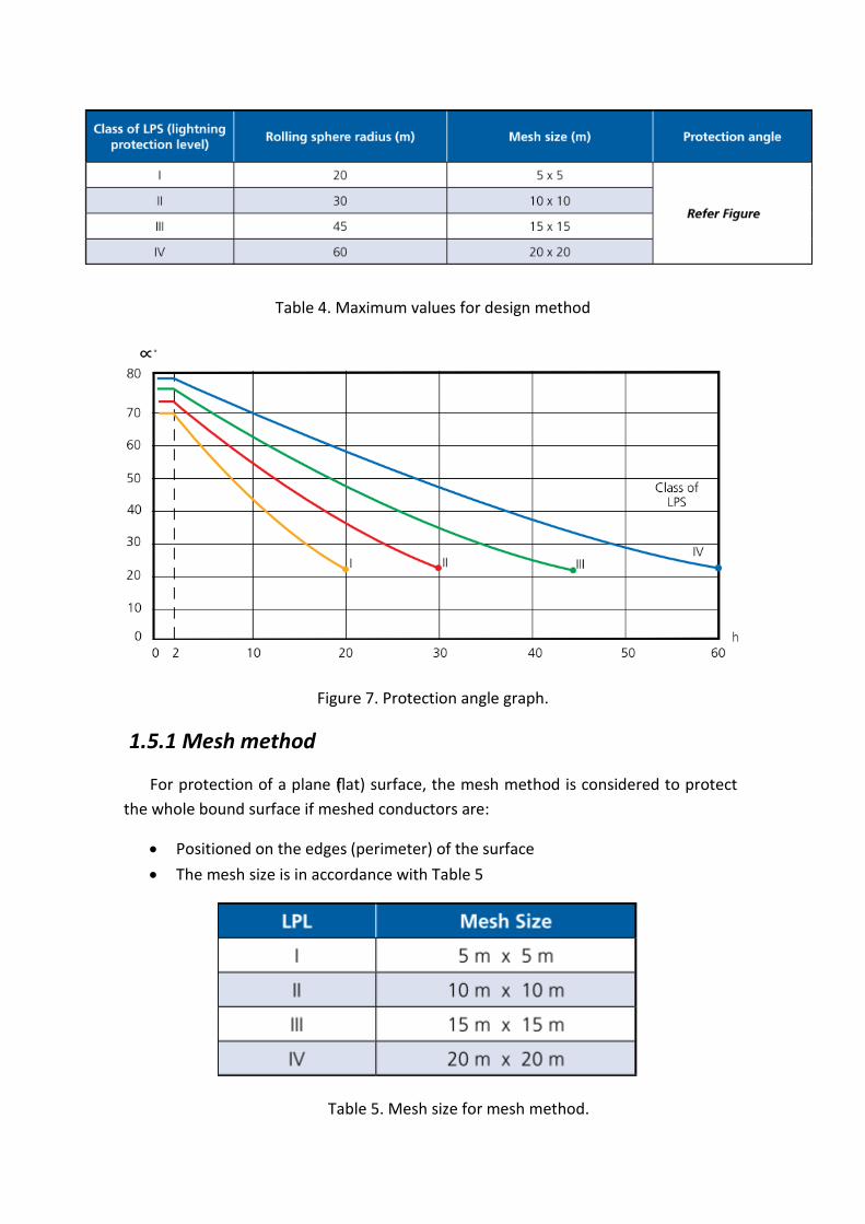
Table 4. Maximum values for design method
Figure 7. Protection angle graph.
1.5.1 Mesh method
For protection of a plane (flat) surface, the mesh method is considered to protect the whole bound surface if meshed conductors are:
• Positioned on the edges (perimeter) of the surface
• The mesh size is in accordance with Table 5
Table 5. Mesh size for mesh method.

• No metallic structures protrude outside the volume
• From each point, at least two separate paths exist to ground (i.e. no dead ends), and these paths follow the most direct routes
Natural components may be used for part of the mesh grid, or even the entire grid. The mesh method is recommended for flat roof surfaces. It is also recommended for the protection of the sides of tall buildings against flashes to the side.
Figure 8. Protection via mesh method
The mesh method should not be used on curved surfaces, but can be used on non-horizontal plane surfaces and compound surfaces. For example on the vertical sides of tall buildings for protection against flashes to the side, or on compound surfaces such as industrial roofs. For compound surfaces, conductors should be placed on the roof ridge lines if the slope exceeds 1/10.
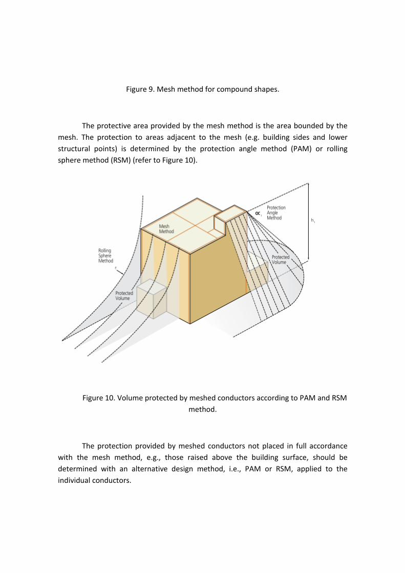
Figure 9. Mesh method for compound shapes.
The protective area provided by the mesh method is the area bounded by the mesh. The protection to areas adjacent to the mesh (e.g. building sides and lower structural points) is determined by the protection angle method (PAM) or rolling sphere method (RSM) (refer to Figure 10).
Figure 10. Volume protected by meshed conductors according to PAM and RSM method.
The protection provided by meshed conductors not placed in full accordance with the mesh method, e.g., those raised above the building surface, should be determined with an alternative design method, i.e., PAM or RSM, applied to the individual conductors.

1.5.2 Protection angle method
Air-terminations (rods/masts and catenary wires) are located so the volume defined by the protection angle (refer to Figure 11) covers the structure to be protected. The height of the air-termination is measured from the top of the air-termination to the surface to be protected. The protection angle method is limited in application to heights that are equal to or less than the corresponding rolling sphere radius.
Figure 11. Protection angle method.
Where the protection angle method alone is employed, multiple rods are generally required for most structures. However the protection angle method is most commonly used to supplement the mesh method, providing protection to items protruding from the plane surface.

Figure 12. Combination protection.
The protection angle method can be used on inclined surfaces, where the height of the rod is the vertical height, but the protection angle is referenced from a perpendicular line from the surface to the tip of the rod.
Figure 13. Protection angle method applied to inclined surface.

Table 6. Height versus horizontal distance using protection angle method.
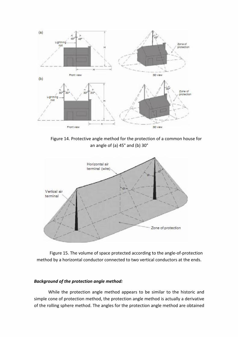
Figure 14. Protective angle method for the protection of a common house for an angle of (a) 45° and (b) 30°
Figure 15. The volume of space protected according to the angle-of-protection method by a horizontal conductor connected to two vertical conductors at the ends.
Background of the protection angle method:
While the protection angle method appears to be similar to the historic and simple cone of protection method, the protection angle method is actually a derivative of the rolling sphere method. The angles for the protection angle method are obtained
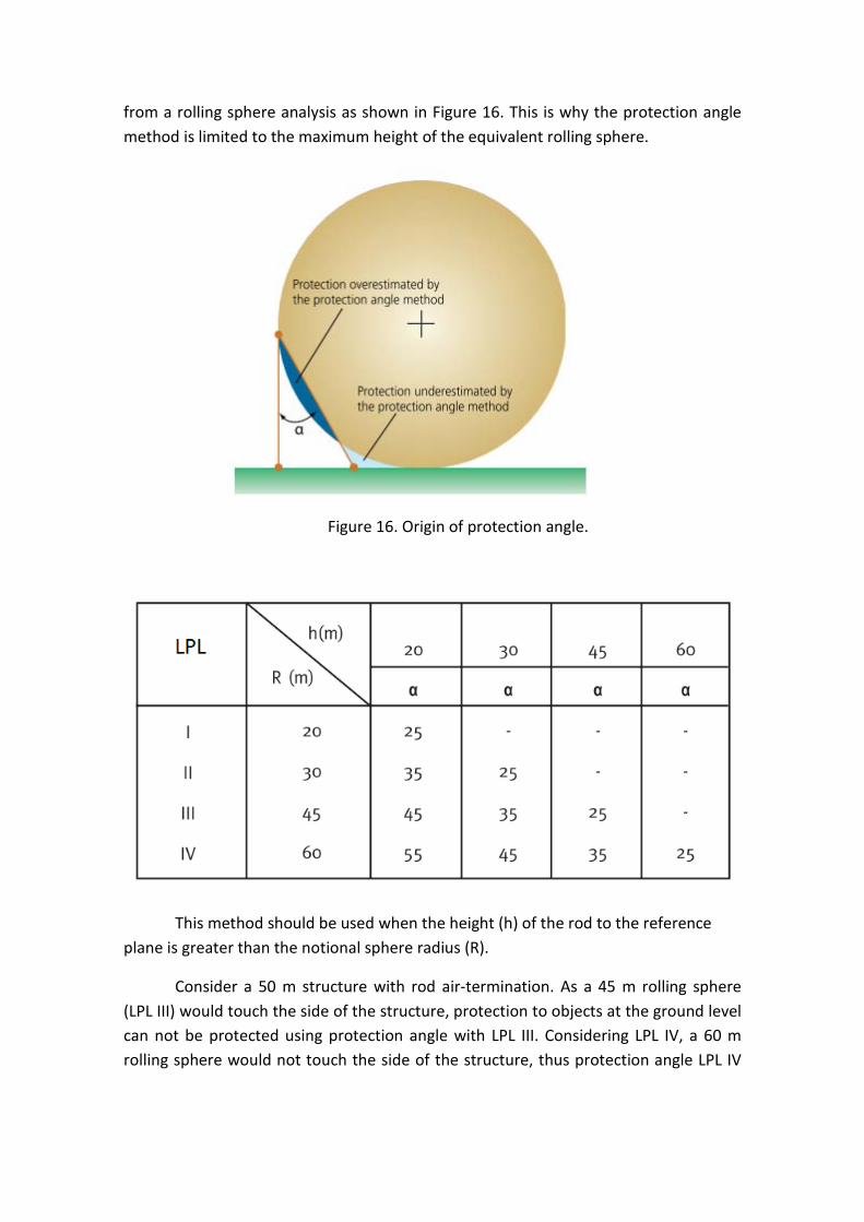
from a rolling sphere analysis as shown in Figure 16. This is why the protection angle method is limited to the maximum height of the equivalent rolling sphere.
Figure 16. Origin of protection angle.
This method should be used when the height (h) of the rod to the reference plane is greater than the notional sphere radius (R).
Consider a 50 m structure with rod air-termination. As a 45 m rolling sphere (LPL III) would touch the side of the structure, protection to objects at the ground level can not be protected using protection angle with LPL III. Considering LPL IV, a 60 m rolling sphere would not touch the side of the structure, thus protection angle LPL IV

can be used with the rod air-termination to determine what objects at the ground level would be protected.
The virtue of the protection angle method is its simplicity in application, but its drawback is that it is a further simplification of the rolling sphere method, hence may not be as reliable or efficient.
The knowledge that the protection angle method is derived from the rolling sphere method helps to understand a common question about its implementation. With reference to Figure 11, it may not be apparent why a α2 is less than a α1 If a second air-terminal is installed to the left of the existing air-terminal, then a α1 and a α2 for the second terminal would be equal. The reason that h2 is used for a α2 is an attempt to duplicate the protection indicated by the rolling sphere method.
1.5.3 The rolling sphere method – “geometric-electrical model”
For lightning flashes to earth, a downward leader grows step-by-step in a series of jerks from the cloud towards the earth. When the leader has got close to the earth within a few tens, to a few hundreds of metres, the electrical insulating strength of the air near the ground is exceeded. A further ”leader” discharge similar to the downward leader begins to grow towards the head of the downward leader: the upward leader. This defines the point of strike of the lightning strike.

Figure 17. Starting upward leader defining the point of strike
The starting point of the upward leader and hence the subsequent point of strike is determined mainly by the head of the downward leader. The head of the downward leader can only approach the earth within a certain distance. This distance is defined by the continuously increasing electrical field strength of the ground as the head of the downward leader approaches. The smallest distance between the head of the downward leader and the starting point of the upward leader is called the final striking distance hB (corresponds to the radius of the rolling sphere).
Immediately after the electrical insulating strength is exceeded at one point, the upward leader which leads to the final strike and manages to cross the final striking distance, is formed. Observations of the protective effect of guard wires and pylons were used as the basis for the so-called “geometric-electrical model”.
This is based on the hypothesis that the head of the downward leader approaches the objects on the ground, unaffected by anything, until it reaches the final striking distance.
The point of strike is then determined by the object closest to the head of the downward leader. The upward leader starting from this point “forces its way through”.
Classification of the lightning protection system and radius of the rolling sphere
As a first approximation, a proportionality exists between the peak value of the lightning current and the electrical charge stored in the downward leader. Furthermore, the electrical field strength of the ground as the downward leader approaches is also linearly dependent on the charge stored in the downward leader, to a first approximation. Thus there is a proportionality between the peak value I of the lightning current and the final striking distance hB (= radius of the rolling sphere):
“r” in m.
“I” in kA.
The protection of structures against lightning is described in IEC 62305-1 (EN 62305-1). Among other things, this standard defines the classification of the individual lightning protection system and stipulates the resulting lightning protection measures. It differentiates between four classes of lightning protection system. A Class I lightning protection system provides the most protection and a Class IV, by comparison, the

least. The interception effectiveness Ei of the air-termination systems is concomitant with the class of lightning protection system, i.e. which percentage of the prospective lightning strikes is safely controlled by the air-termination systems. From this results the final striking distance and hence the radius of the “rolling sphere”. The correlations between class of lightning protection system, interception effectiveness Ei of the air-termination systems, final striking distance / radius of the “rolling sphere” and current peak value are shown in the next table.
Table 7. Relations between lightning protection level, interception criterion Ei , final striking distance hB and min. peak value of current I
Taking as a basis the hypothesis of the “geometric-electrical model” that the head of the downward leader approaches the objects on the earth in an arbitrary way, unaffected by anything, until it reaches the final striking distance, a general method can be derived which allows the volume to be protected of any arrangement to be inspected. Carrying out the rolling sphere method requires a scale model (e.g. on a scale of 1:100) of the building / structure to be protected, which includes the external contours and, where applicable, the air-termination systems. Depending on the location of the object under investigation, it is also necessary to include the surrounding structures and objects, since these could act as “natural protective measures” for the object under examination.
Furthermore, a true-to-scale sphere is required according to the class of lightning protection system with a radius corresponding to the final striking distance (depending on the class of lightning protection system, the radius r of the “rolling sphere” must correspond true-to-scale to the radii 20, 30, 45 or 60 m). The centre of the “rolling sphere” used corresponds to the head of the downward leader towards which the respective upward leaders will approach.
The “rolling sphere” is now rolled around the object under examination and the contact points representing potential points of strike are marked in each case. The “rolling sphere” is then rolled over the object in all directions. All contact points are marked again. All potential points of strike are thus shown on the model; it is also

possible to determine the areas which can be hit by lateral strikes. The naturally protected zones resulting from the geometry of the object to be protected and its surroundings can also be clearly seen. Air-termination conductors are not required at these points as we can see in the next picture.
Figure 18. Schematic application of the “rolling sphere” method at a building with considerably structured surface
It must be borne in mind, however, that lightning footprints have also been found on steeples in places not directly touched as the “rolling sphere” rolled over. This is traced to the fact that, among other things, in the event of multiple lightning flashes, the base of the lightning flash moves because of the wind conditions. Consequently, an area of approx. one metre can come up around the point of strike determined where lightning strikes can also occur.
In other hand, the “rolling sphere” with the smaller radius (according to a class of lightning protection system with a higher lightning protection level) naturally touches also the model at all points already touched by the “rolling sphere” with the larger radius. Thus, it is only necessary to determine the additional contact points.
As demonstrated, when dimensioning the air-termination system for a structure, or a structure mounted on the roof, the sag of the rolling sphere is decisive.
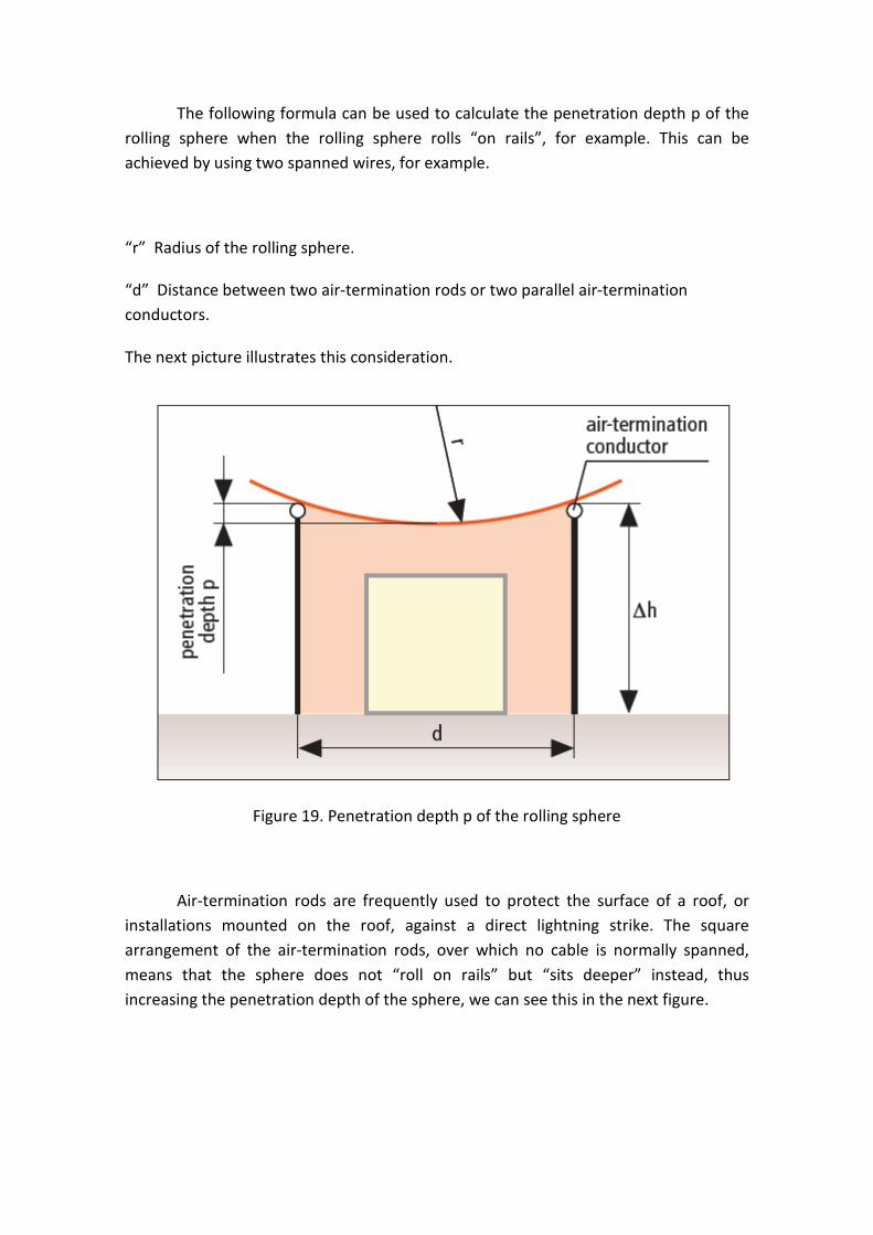
The following formula can be used to calculate the penetration depth p of the rolling sphere when the rolling sphere rolls “on rails”, for example. This can be achieved by using two spanned wires, for example.
“r” Radius of the rolling sphere.
“d” Distance between two air-termination rods or two parallel air-termination conductors.
The next picture illustrates this consideration.
Figure 19. Penetration depth p of the rolling sphere
Air-termination rods are frequently used to protect the surface of a roof, or installations mounted on the roof, against a direct lightning strike. The square arrangement of the air-termination rods, over which no cable is normally spanned, means that the sphere does not “roll on rails” but “sits deeper” instead, thus increasing the penetration depth of the sphere, we can see this in the next figure.
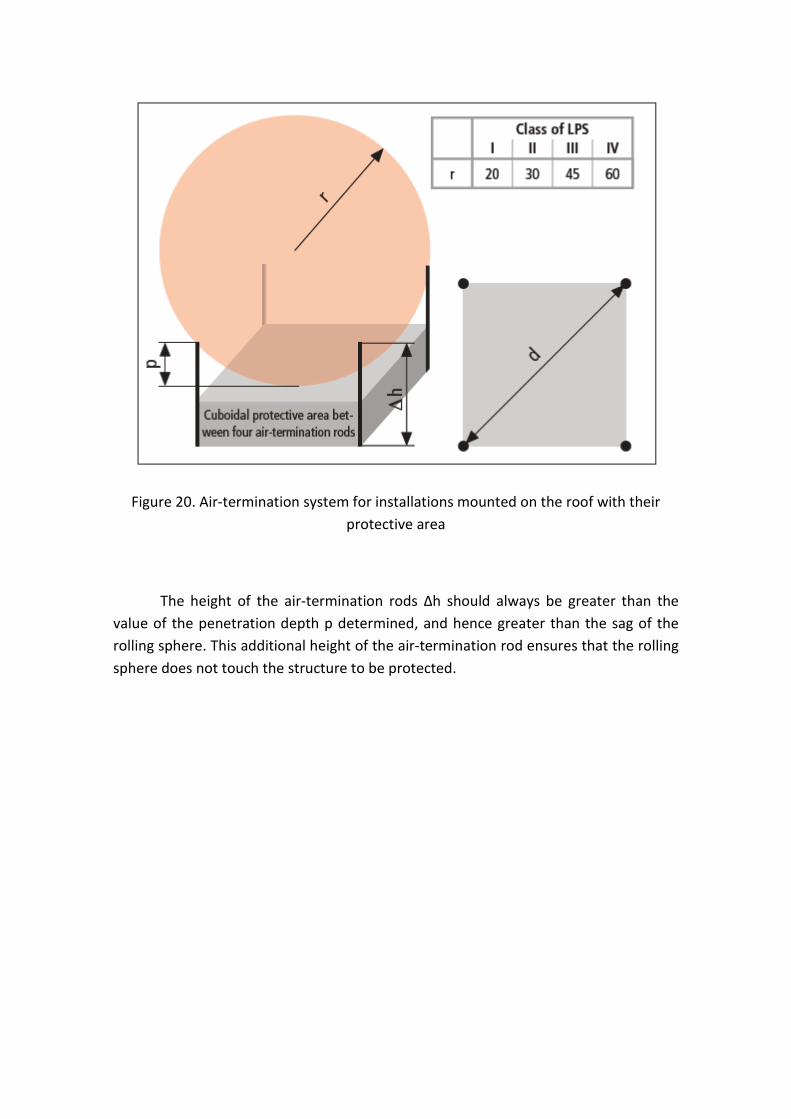
Figure 20. Air-termination system for installations mounted on the roof with their protective area
The height of the air-termination rods Δh should always be greater than the value of the penetration depth p determined, and hence greater than the sag of the rolling sphere. This additional height of the air-termination rod ensures that the rolling sphere does not touch the structure to be protected.

Figure 21. Calculation Δh for several air-termination rods according to rolling sphere method
Another way of determining the height of the air-termination rods is using the following table. The penetration depth of the rolling sphere is governed by the largest distance of the air-termination rods from each other. Using the greatest distance, the penetration depth p (sag) can be taken from the table. The air-termination rods must be dimensioned according to the height of the structures mounted on the roof (in relation to the location of the air-termination rod) and also the penetration depth what is shown in the previous figure.
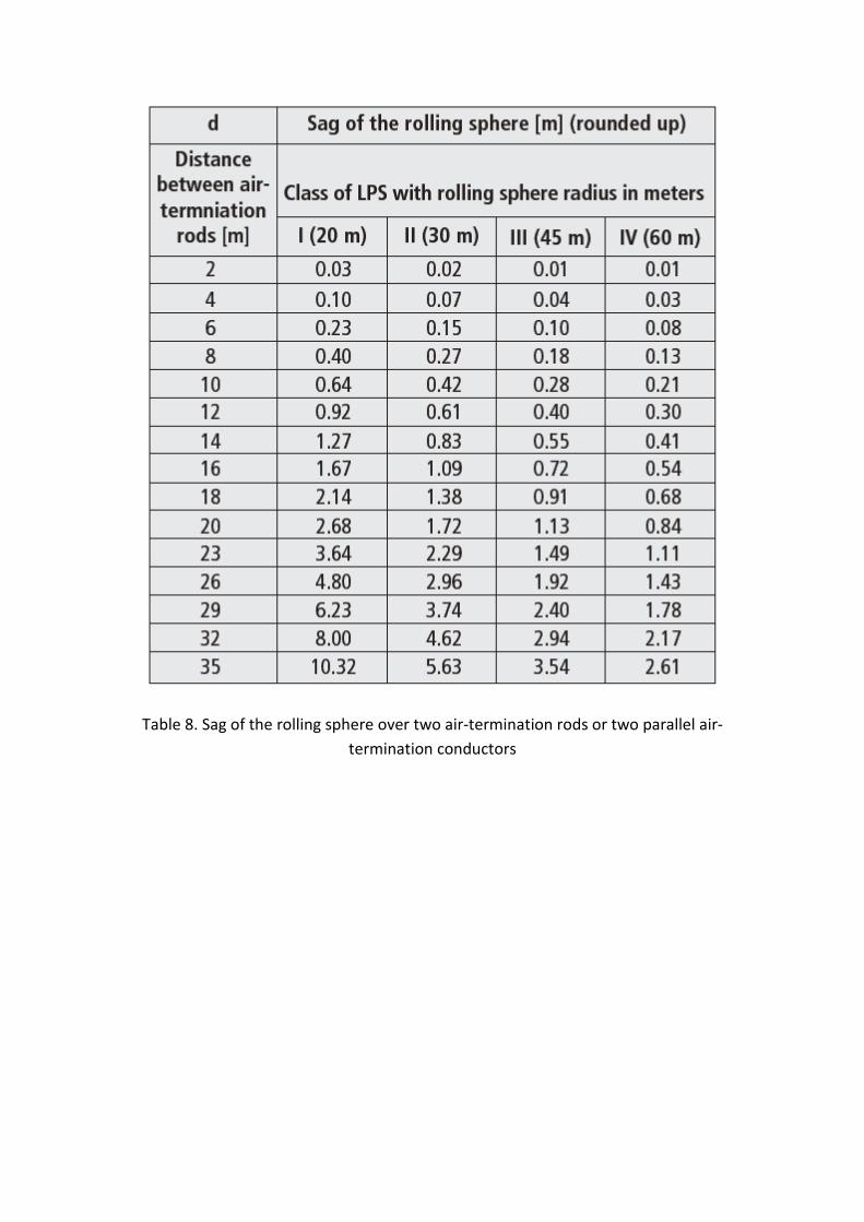
Table 8. Sag of the rolling sphere over two air-termination rods or two parallel air-termination conductors

1.6 Lightning damage
1.6.1 What does lightning do to people?
Cloud-to-ground lightning can kill and injure people by direct or indirect means. It is not known if all people are killed who are directly struck by the flash itself. The lightning current can branch off to a person from a tree, fence, pole, or other tall object. In addition, flashes may conduct their current through the ground to a person after the flash strikes a nearby tree, antenna, or other tall object. The current also may travel through power or telephone lines to a person who is in contact with electric appliances, tools, electronics, or a corded telephone. Lightning can also travel through plumbing pipes and water to a person in contact either with a plumbing fixture or a person in water, including bathtubs, pools, and the running water of a shower.
1.6.2 Damage to the human body
Lightning affects the many electrochemical systems in the body. People struck by lightning can suffer from nerve damage, memory loss, personality change, and emotional problems. There is a national support group for lightning and electric shock survivors.
An example is some single nerve cells, such as those extending from the brain to the foot, can be as long as 6 feet or more. These types of cells are most prone to lightning damage due to the instantaneous potential difference across the length of the cell as lightning begins to enter the body.
The intense heat of the lightning stroke can turn sweat instantly to steam and the tremendous pressure of the steam has been known to blow people's boots, shoes, and clothing off them. In places where metal is in contact with or close proximity to the body, such as jewelry or belt buckles, burn marks are found. Likewise, burn marks are found in places where the body had been sweaty, such as the feet, underarms, and chest.
According to a study of Ronald L. Holle and Raúl E. López, males account for 84% of lightning fatalities and 82% of injuries.
Men can take comfort in the fact that the actual number of deaths and injuries from lightning strikes has decreased in the past 35 years. Holle's team attributes 30 percent of the decrease in lightning deaths to improved forecasts and warnings, better lightning awareness, more substantial buildings, and socioeconomic changes. They attribute an additional 40 percent to improved medical care and communications.

The National Weather Service publication Storm Data recorded 3,239 deaths and 9,818 injuries from lightning strikes between 1959 and 1994. Only flash floods and river floods cause more weather-related deaths. But according to Dr. Elisabeth Gourbière of the Electricité de France, Service des Etudes Médicales, only 20 percent of lightning victims are immediately struck dead. Still, many doctors do not fully understand how to treat the injuries of the other 80 percent of lightning victims who survive a strike.
Says Gourbière, "The pathology of lightning, or keraunopathy, is known only to a few specialists."
Most doctors are more familiar with electrical shocks, such as those received by industrial workers when they have an accidental run-in with high-voltage equipment. But lightning injuries are not the same as electrical shocks. For one thing, the contact voltage of a typical industrial electrical shock is 20 to 63 kilovolts, while a lightning strike delivers about 300 kilovolts.
Industrial shocks rarely last longer than half a second (500 milliseconds) because a circuit breaker opens or the person is thrown far from the live conductor. Lightning strikes have an even shorter duration, only lasting up to a few milliseconds. Most of the current from a lightning strike passes over the surface of the body in a process called "external flashover."
Both industrial shocks and lightning strikes result in deep burns at point of contact - for industry the points of contact are usually on the upper limbs, hands and wrists, while for lightning they are mostly on the head, neck and shoulders. Industrial shock victims sometimes exhibit deep tissue destruction along the entire current path, while lightning victims’ burns seem to center at the entry and exit points. Both industrial shock and lightning victims may be injured from falling down or being thrown, and the leading cause of immediate death for both is cardiac or cardiopulmonary arrest.
If you survive a shock, you still have to deal with the consequences of the electrical burns. Industrial shock burns can lead to kidney failure, infection, muscle and tissue damage, or amputation. Lightning burns are exceptionally life threatening.
Gourbière says that 70 percent of lightning survivors experience residual effects, most commonly affecting the brain (neuropsychiatric, vision and hearing). These effects can develop slowly, only becoming apparent much later.
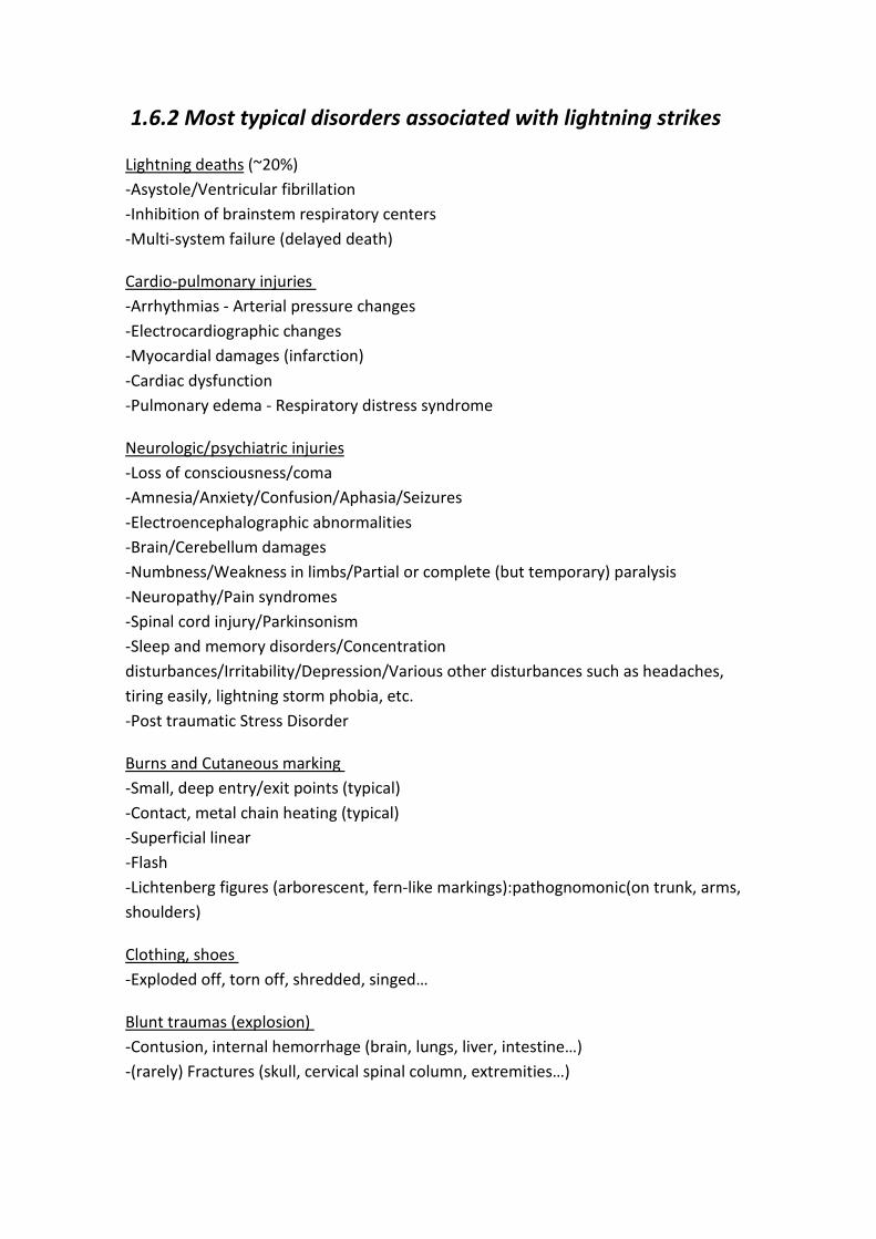
1.6.2 Most typical disorders associated with lightning strikes
Lightning deaths (~20%) -Asystole/Ventricular fibrillation -Inhibition of brainstem respiratory centers -Multi-system failure (delayed death)
Cardio-pulmonary injuries -Arrhythmias - Arterial pressure changes -Electrocardiographic changes -Myocardial damages (infarction) -Cardiac dysfunction -Pulmonary edema - Respiratory distress syndrome
Neurologic/psychiatric injuries -Loss of consciousness/coma -Amnesia/Anxiety/Confusion/Aphasia/Seizures -Electroencephalographic abnormalities -Brain/Cerebellum damages -Numbness/Weakness in limbs/Partial or complete (but temporary) paralysis -Neuropathy/Pain syndromes -Spinal cord injury/Parkinsonism -Sleep and memory disorders/Concentration disturbances/Irritability/Depression/Various other disturbances such as headaches, tiring easily, lightning storm phobia, etc. -Post traumatic Stress Disorder
Burns and Cutaneous marking -Small, deep entry/exit points (typical) -Contact, metal chain heating (typical) -Superficial linear -Flash -Lichtenberg figures (arborescent, fern-like markings):pathognomonic(on trunk, arms, shoulders)
Clothing, shoes -Exploded off, torn off, shredded, singed…
Blunt traumas (explosion) -Contusion, internal hemorrhage (brain, lungs, liver, intestine…) -(rarely) Fractures (skull, cervical spinal column, extremities…)
Auditory and ocular injuries
-Tympanic membrane ruptured (typical) -Deafness/Tinnitus/Vertigo -Transient blindness/Photophobia-Conjunctivitis - Corneal damage -Retinal abnormalities (macular hole) - optic neuritis -Cataract
Lightning injuries are varied and take many different forms. The most dangerous (and possibly fatal) immediate complications are cardiovascular and neurologic. It must be kept in mind that only immediate and effective cardiorespiratory resuscitation (started by rescuers), followed as soon as possible by emergency medical treatment, can save victims who are in cardiopulmonary arrest, or avert the serious consequences of cerebral hypoxia. Some victims remain in a coma despite intensive resuscitation and die of secondary causes including hemorrhages and multiple lesions (encephalic, cardiac, pulmonary, intra-abdominal).
1.6.4 Lightning disasters
Jun 26, 1807. Lightning strikes in Luxembourg
On this day in 1807, lightning hits a gunpowder factory in the small European country of Luxembourg, killing more than 300 people. Lightning kills approximately 73 people every year in the United States alone, but victims are almost always killed one at a time. The Luxembourg disaster may have been the most deadly lightning strike in history.
The earth experiences 8 to 9 million lightning strikes every single day. In a typical year, the United States will see about 70,000 thunderstorms somewhere in its territory. This produces approximately 20 million lightning strikes annually. A bolt of lightning can reach 50,000 degrees Fahrenheit in instant heat. There are 100 million volts in an average lightning bolt, which can be as much as five miles long.
In 1807, Luxembourg was occupied by Napoleon's army. The French dictator used the country to stockpile weapons and ammunition. Many underground bunkers were built for this purpose. In the southern Luxembourg city of Kirchberg, a fortress built in 1732 was used as an armory.
When lightning struck the fortress on June 26, the ammunition housed within ignited on contact, causing a massive explosion. Two entire blocks were completely

razed by the blast, which caused several other fires to rage nearby. The London Times later reported, this city has been plunged into the greatest consternation and distress.
Jul 1, 2011. School in Uganda
Eighteen children and a teacher have been killed after lightning struck a school in the Masindi area of Uganda. It is the second time the Runyanya Primary School has been hit.
Across Uganda, another 12 people have been killed by lightning during that last week. Meterologists say the reason for the strikes is a surge of moist air coming through the Congo Basin, but the government has also admitted that many buildings are not fitted with lightning conductors.
Aug, 1769. Brescia lightning
In August of 1769, lightning struck the tower of the Church of the Nazaire in Brescia, Italy. The current passed through the vaults where 207,000 pounds of gunpowder had been stored for safekeeping. You can tell where this is going. The aftermath destroyed a sixth of the city and killed 3,000 residents. The British parliament responded by passing two acts establishing standards for the manufacture and storage of gunpowder in private hands, eventually leading to an argument over how to best protect arsenal from lightning strikes.
Dec 8, 1963. Pan American Flight 214
The worst lightning strike death toll occurred when lightning hit a Pan American Boeing 707 en route from Puerto Rico to Philadelphia, killing all 81 on board. It’s the only US airliner lost to lightning. Lightning struck the left wing of the 707 and hit the fuel vapor mixture stored in a reserve fuel tank, igniting it. The airplane exploded midair and crashed near Elkton, Maryland.
Flight 214 was in a holding pattern, awaiting approval to land at Philadelphia International Airport when it was struck. On fire, a large portion of the left wing separated in flight. The pilot managed to maintain control for a few seconds before the plane crashed. While examining the wreckage, officials noticed numerous spots where the metal surface and rivet heads appeared melted. Also, an irregular-shaped hole surrounded by fused metal indicated the presence of high heat.
Lightning charges can be hazardous to airplane fuel systems because lightning is able to ignite the fuel vapor in the tanks. As a result of this tragedy, the FAA insisted that all commercial jet liners be fitted with lightning discharge wicks. Still, on average, every commercial airliner is struck in flight at least once per year.
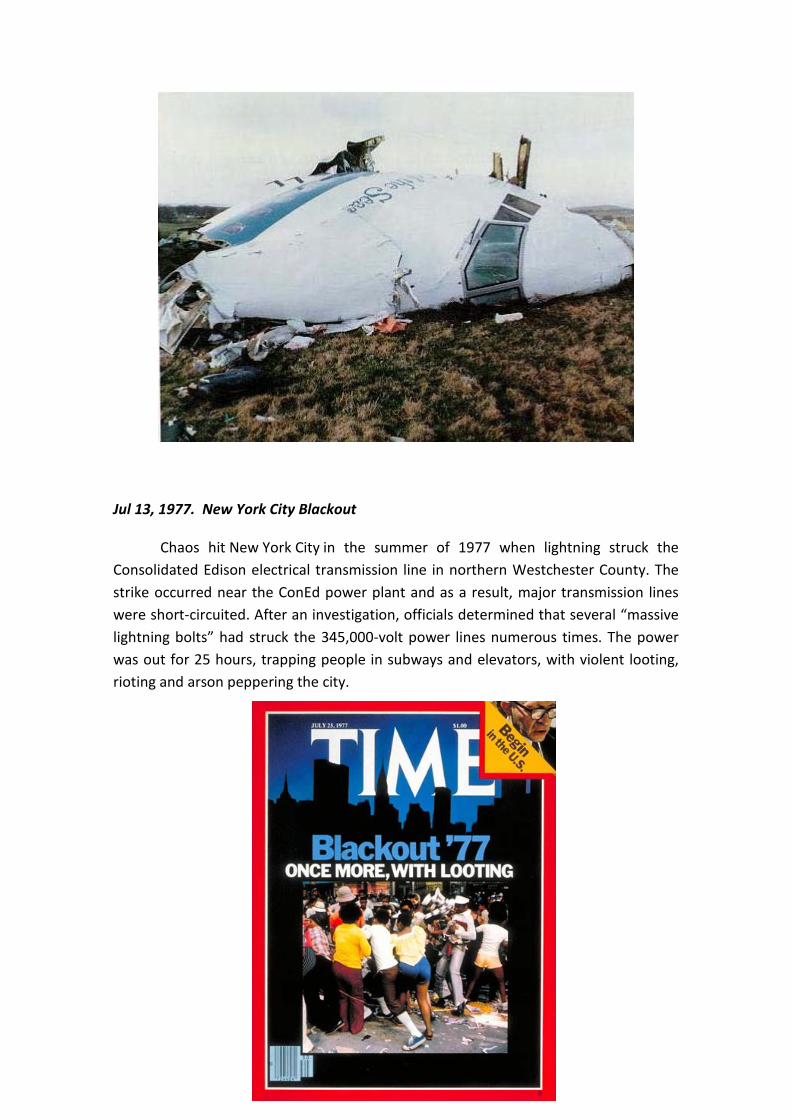
Jul 13, 1977. New York City Blackout
Chaos hit New York City in the summer of 1977 when lightning struck the Consolidated Edison electrical transmission line in northern Westchester County. The strike occurred near the ConEd power plant and as a result, major transmission lines were short-circuited. After an investigation, officials determined that several “massive lightning bolts” had struck the 345,000-volt power lines numerous times. The power was out for 25 hours, trapping people in subways and elevators, with violent looting, rioting and arson peppering the city.
Mar 26, 1987. Lightning in Space
The Atlas-Centaur 67 was a 137-foot, $78 million rocket carrying $83 million of military communication equipment. Spinning out of control 51 seconds after liftoff, the rocket had to be destroyed immediately to prevent any off-course veering that might have endangered populated areas along the Florida coast. The flaming wreckage fell into the Atlantic Ocean three miles from Cape Canaveral.
Afterwards, videotape released by NASA showed a lightning bolt clearly flashing out of the rain clouds into which the Atlas-Centaur had vanished. Safety officials determined that at 14,250 feet the rocket disappeared into the clouds, losing control and disrupting all communications. Lightning experts said that a rocket penetrating a storm cloud could attract electrical charges much like a tree or a tall building, such as the Empire State Building. NASA officials blamed the Air Force for shoddy weather reports, and defended their decision to launch a rocket into cloudy skies.
This was not the first time lightning and NASA butted heads. On November 14, 1969, the Apollo 12 was struck thirty seconds into liftoff. Systems failed temporarily, but the astronauts managed to regain control.
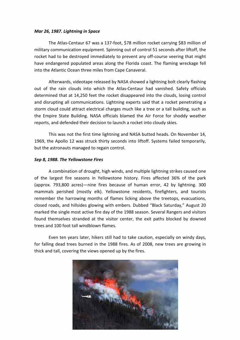
Sep 8, 1988. The Yellowstone Fires
A combination of drought, high winds, and multiple lightning strikes caused one of the largest fire seasons in Yellowstone history. Fires affected 36% of the park (approx. 793,800 acres)—nine fires because of human error, 42 by lightning. 300 mammals perished (mostly elk). Yellowstone residents, firefighters, and tourists remember the harrowing months of flames licking above the treetops, evacuations, closed roads, and hillsides glowing with embers. Dubbed “Black Saturday,” August 20 marked the single most active fire day of the 1988 season. Several Rangers and visitors found themselves stranded at the visitor center, the exit paths blocked by downed trees and 100 foot tall windblown flames.
Even ten years later, hikers still had to take caution, especially on windy days, for falling dead trees burned in the 1988 fires. As of 2008, new trees are growing in thick and tall, covering the views opened up by the fires.

Jul 23, 2011. Wenzhou train collision
On 23 July, at roughly 20:00 CST, CRH train D3115 (CRH1-046B), carrying 1,072 people and travelling from Hangzhou to Fuzhou South came to a halt over a viaduct near the Ou River. Shortly after, CRH train D301 (CRH2-139E), carrying 558 people and running from Beijing South to Fuzhou, crashed into the rear-end of the stationary D3115.
The cause of the crash was initially said to be a lightning storm occurring 20 miles (32 km) south and 60 miles (97 km) west of the viaduct. Lightning reportedly struck the first train, which caused it to stop on the tracks. However, five days after the incident, the Beijing National Railway Research & Design Institute of Signals and Communications Co. Ltd., a railway research institute, claimed responsibility, stating in a report that a signal on the track failed to turn red, and staff failed to notice the error.
A much more detailed description of what happened in the accident, correcting earlier accounts, was published in the December 2011 report of the official investigation. The first train D3115 was stopped not by losing power as a result of the lightning strike, but was stopped by the signal system, the Automatic Train Protection (ATP). The lightning had struck a trackside LKD2-T1 signal assembly, burning out its fuses, and violating the rule that it should be 'fail-safe' this had caused an incorrect indication in the control center that the track section containing train D3115 was unoccupied (the so-called 'green signal'). The driver He Li of train D3115 worked to override the ATP, and after more than seven minutes of waiting, at 8.29 p.m. he got the train moving again, overriding the ATP. As train D3115 entered the next section of track, where the track circuits which indicate the presence of the train were working correctly, the control center now saw that the track section was occupied. But driver Pan Yiheng of the following train D301 had already been given instructions to proceed onto the section of track where D3115 had been stopped, when the control center had a false indication that the track was unoccupied. Despite a message from the control center that D301 should proceed with caution, less than half a minute later train D301 running at 99 km/h (62 mph) collided with train D3115.
The fifteenth and sixteenth coaches at the rear of D3115 and the front four coaches of D301 were derailed — four coaches fell off the viaduct. Three carriages came to rest horizontally on the ground below while the fourth came to rest vertically, one end on the ground and one end leaning against the viaduct.
The various medical teams responding to the accident consisted of staff from Zhejiang No. 1 Hospital, Zhejiang No. 2 Hospital, Zhejiang Provincial People's Hospital and Taizhou Hospital. The evening of the event, 500 Wenzhou residents gave blood in response to early radio appeals by the local blood bank.

A survivor, Liu Hongtaohe, recalled that "the train suddenly shook violently, casting luggage all around. Passengers cried for help but no crew responded" in an interview with China Central Television. CCTV reported on 25 July that the Railways Ministry had declared that 39 people were killed and 192 injured. Two-year-old Xiang Weiyi was the last person rescued, 21 hours after the train crash. Her parents had been killed in the crash.
May 15, 2012. French Hollande changes plane after lightning strike
A presidential jet carrying newly inaugurated French President Francois Hollande was hit by lightning en route to Berlin and forced to turn back to Paris, but the Socialist was unharmed and took off again in another plane, a presidential source said.
Hollande, who was sworn in as president on Tuesday morning, was expected to arrive with a delay of one and a half hours for his first meeting with German Chancellor Angela Merkel after he set off in the second aircraft.

2.Specification
2.1 Weather
The building we are considering (Marqués de Valdecilla Hospital) is located in Santander, a city on the seashore. Santander is the capital of Cantabria, in northern of Spain.
In first place we are going to focus on Spain climate.
The climate varies tremendously in Spain, due to its large size.
The vast central plateau, or Meseta, has a continental climate with hot, dry summers and cold winters. Rain generally falls in spring and autumn. The mountains surrounding the plateau have a higher rainfall and often they experience heavy snowfalls in winter.
On the Mediterranean coast, the climate is moderate with rain in spring and autumn. Murcia has an almost African climate and is characterized by numerous palm trees. Rainfall is low and the calina, or heat haze, is common during summer.
On the Atlantic coast, the summers are cooler and fairly heavy rainfall occurs during winter.
North of the Cantabrian Mountains, the Basque Country, Cantabria, Asturias and Galicia have a maritime climate, with cool summers and mild winters. The weather is often cloudy with frequent rainfall.
We can observe the figure 22, where the average annual thunderstorms in Spain appear. In Cantabria, on the north as we see in the figure, has a high average storm, of 15 to 20 days in a year.

Figure 22. Average annual days with thunderstorm
In the table below we can see data on the storms in different parts of the region, paying special attention to Santander.
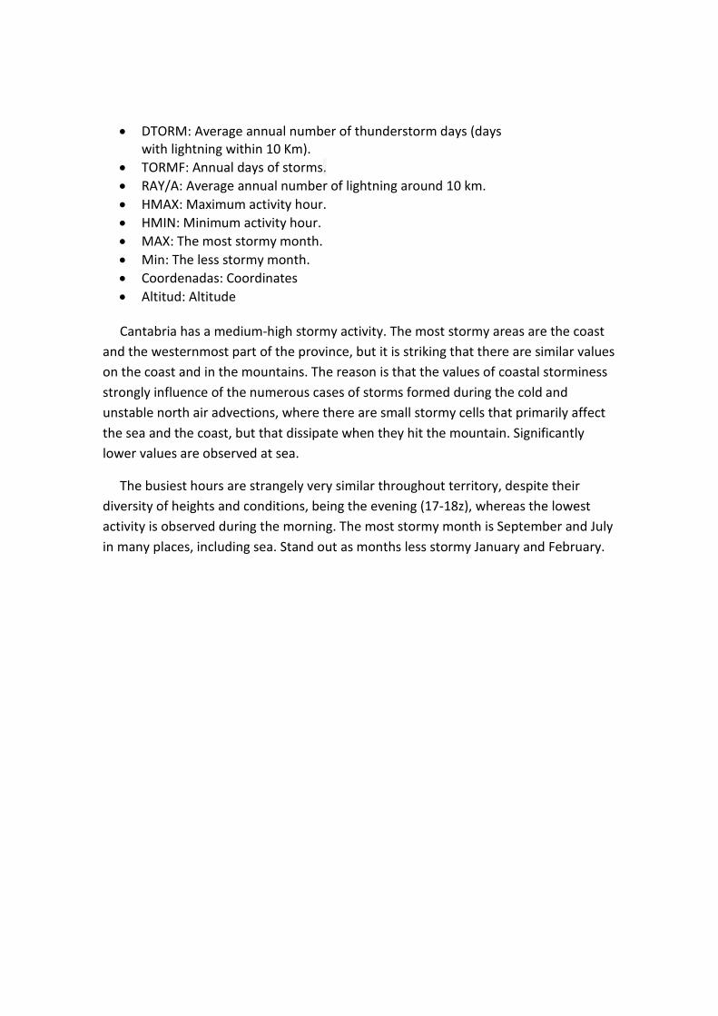
• DTORM: Average annual number of thunderstorm days (days with lightning within 10 Km).
• TORMF: Annual days of storms. • RAY/A: Average annual number of lightning around 10 km. • HMAX: Maximum activity hour. • HMIN: Minimum activity hour. • MAX: The most stormy month. • Min: The less stormy month. • Coordenadas: Coordinates • Altitud: Altitude
Cantabria has a medium-high stormy activity. The most stormy areas are the coast and the westernmost part of the province, but it is striking that there are similar values on the coast and in the mountains. The reason is that the values of coastal storminess strongly influence of the numerous cases of storms formed during the cold and unstable north air advections, where there are small stormy cells that primarily affect the sea and the coast, but that dissipate when they hit the mountain. Significantly lower values are observed at sea.
The busiest hours are strangely very similar throughout territory, despite their diversity of heights and conditions, being the evening (17-18z), whereas the lowest activity is observed during the morning. The most stormy month is September and July in many places, including sea. Stand out as months less stormy January and February.

2.2 Marqués de Valdecilla hospital
Marqués de Valdecilla University Hospital, Valdecilla popularly known, is a hospital located in the city of Santander (Cantabria, Spain). It belongs to the Cantabrian Health Service.
Figure 23. General view of the hospital
The Valdecilla Nursing Home was founded in end of the first third of the twentieth century. In the hospital's history we can distinguish three different stages, one that lying since its foundation in 1929 until 1969, one that extends from that date to 1982, and the last from the 80's to the present .
Constitution of the Valdecilla House Health
The nursing home was established thanks to the contribution of Ramón Pelayo de la Torriente, Marquis of Valdecilla, with the close collaboration of his niece Dona Maria Luisa Pelayo, Marquise of Pelayo. The existence in Santander of a pro new hospital association, working in the attempt to build a center that came to replace the old Hospital of St. Raphael, found their larger feasibility channels in the person of the Marquis Valdecilla, who assumed the role of founder, providing the financial means to carry out a new hospital that was not simply the replacement of the old one, if not, according to his personal qualities of extraordinary intelligence and future vision,

creating an institution, in 1929, responding to the characteristics of authentic hospital care renewal. In the developing of projects for the new hospital, the Marquis de Valdecilla had many important advice, and especially from the Gregorio Marañón Professor. The hospital construction project was entrusted to Bringas architect.
The cost of buildings, installations, furniture and library amounted to 16.628.582 pesetas. It was recognized as a particular charity Royal Order of April 10, 1928, and in the same year the Santander Provincial Deputation agrees to close the St. Raphael Hospital and Valdecilla starts to take care of patients who had to take care by legal mandatory.
Note that were added to this organization the Institute of Post-Graduate Medical and Nursing School, which years later contributed to the rise in national health care level.
The Valdecilla House of Health medical staff is set since its inception and continues until 1969, with the following services (17 in total): Pathology and Hematology, Cardiology, Nutrition and Endocrinology, Dermo-Sifiolography; Digestive, Dentistry , Physiotherapy, Gynecology and Obstetrics, Bones and Joints, Infections and Laboratories, Neurology and Psychiatry, Ophthalmology, Otorhinolaryngology, Child Care, Chemistry and Pharmacy, Respiratory, Urology.
After 1969
The crisis dragged on and got worse as the economic and institutional problems were not resolved. However, the hospital continued with an excellent care level.
Is set years later, an association for the Valdecilla Hospital and the Cantabria Residence, which becomes a Social Security Special Center, and to adapt to this change, Valdecilla becomes General Hospital and Cantabria Health Residence transformed into a Maternal and Child Center, receiving the whole the name of National Medical Center "Marqués de Valdecilla". This project was signed on June 22, 1972, and the Social Security was responsible of administrative economic management.
Is worthy mention the creation of the Faculty of Medicine in 1972, although the first course would not start until January 10, 1973, with Segundo López Vélez as the

director of Valdecilla and like dean-Commissioner since 1969. It was used the powerful system of Valdecilla and aids from the Provincial Deputation for the development of the faculty.
Present
In this way begins the current phase of Valdecilla Hospital, in which is consolidated as General Hospital and a leader enterprise in number of employees in Cantabria, being a reference and essential institution of the autonomous community. Valdecilla has been the most influential institution in the scientific, social and even economic Cantabria. Nowadays is currently under construction, with the completion of phases 1 and 2 of it and starting the third phase. Currently the health center is composed by three sets of buildings:
- The own Marqués de Valdecilla University Hospital. - The General Residence (was demolished in April 2008). - Nine wards of the old " Valdecilla Health House." - The Nursing University School, inside the University of Cantabria. - Building "November 2" Trauma old building. - Building " South Valdecilla". - Cantabria Hospital (popularly known as Residence), is the maternity hospital
and now of the Internal Medicine, Neurology, Endocrionología, Rheumatology and Respiratory services.
- Vargas Specialty Center, outpatient.
The hospital facilities have continued to be extended, however include the deterioration of the same, which was present in the 90's with the collapse of the Traumatology building north facade, which occurred in the morning of 2 November 1999. The collapse killed four workers of the hospital and left 15 injured people. The incident showed the notorious deterioration that the Hospital had been suffering over the years.

Figure 24. Here we can see the reconstruction of the north facade
I have decided to design the lightning protection of such important building like this hospital because different reasons rank from most to least importance.
These reasons are based on:
- The responsibility of protecting a lot of people who are injured and are not able to move themselves and also the healthy people as relatives of the hospitalized people or workers of the hospital itself.
- The orography in where the hospital is situated. In Santander (Spain), this hospital is localized on the top of the city and the influence of saltwater is very different than if it were built on the bottom of the city, near the sea.
- The importance of protecting many different and very expensive equipment.
- The background. In the morning of 2 of November in 1999, the northwest façade of the hospital collapsed and caused the death of four hospital workers and injured another fifteen people. The incident showed the deterioration that the hospital had been suffering over the years. The news shocked the whole country. The village will not withstand another catastrophe.

2.2.1 Risks
Once, having the knowledge about position, weather in its location, main characteristics of the building, principal uses, influx of people, fire hazard, etc. we can analized the different kind of risks and with all of these, select the protection level in order to design the lightning protection system.
As we have explained in the Risk point, there are four types of risk depending on the four types of looses:
L1- Loss of human life.
L2- Loss of essential service to the public.
L3- Loss of cultural heritage.
In the case of Marqués de Valdecilla Hospital, the risk of human life looses is very important. We have to considerate that it is such a huge building that house thousands of people, both injury people and relatives and all the hospital staff. Furthermore, the evacuation of injury people will turn really difficult due to their condition.
On the other hand, the importance of protecting many different and very expensive equipment that are donated by big enterprises or are bought by the Cantabrian government, which is a big responsibility too. The hospital is equipped with:
3 CAT (computerized axial tomography)
1 PET/CT (Positron emission tomography - computed tomography)
1 Magnetic resonance
3 Gamma cameras
2 Hemodynamic rooms
2 Digital subtraction angiography
1 Extracorporeal Lithotripsy by shock wave
1 Cobalt pump
The failure of any of these equipment will be traduce in a loss of essential service to the public.
An finally we can point that all of these damages will turn into very important economic looses, and due to the financial crisis we are living in, these looses would result in an unaffordable expense.
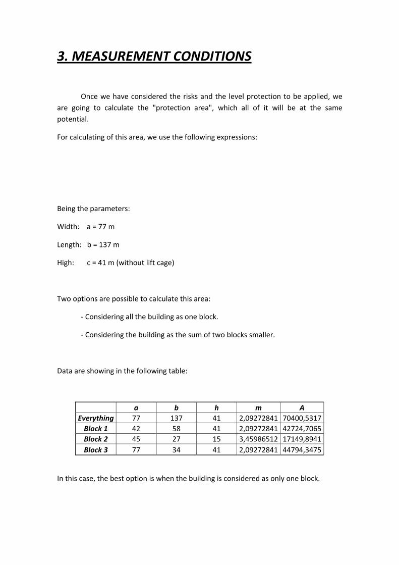
3. MEASUREMENT CONDITIONS
Once we have considered the risks and the level protection to be applied, we are going to calculate the "protection area", which all of it will be at the same potential.
For calculating of this area, we use the following expressions:
Being the parameters:
Width: a = 77 m
Length: b = 137 m
High: c = 41 m (without lift cage)
Two options are possible to calculate this area:
- Considering all the building as one block.
- Considering the building as the sum of two blocks smaller.
Data are showing in the following table:
a b h m A Everything 77 137 41 2,09272841 70400,5317
Block 1 42 58 41 2,09272841 42724,7065 Block 2 45 27 15 3,45986512 17149,8941 Block 3 77 34 41 2,09272841 44794,3475
In this case, the best option is when the building is considered as only one block.
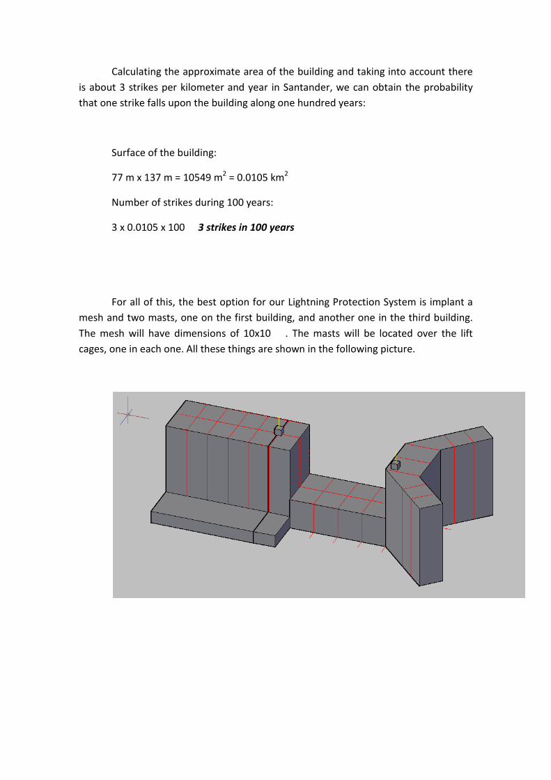
Calculating the approximate area of the building and taking into account there is about 3 strikes per kilometer and year in Santander, we can obtain the probability that one strike falls upon the building along one hundred years:
Surface of the building:
77 m x 137 m = 10549 m2 = 0.0105 km2
Number of strikes during 100 years:
3 x 0.0105 x 100 3 strikes in 100 years
For all of this, the best option for our Lightning Protection System is implant a mesh and two masts, one on the first building, and another one in the third building. The mesh will have dimensions of 10x10 . The masts will be located over the lift cages, one in each one. All these things are shown in the following picture.
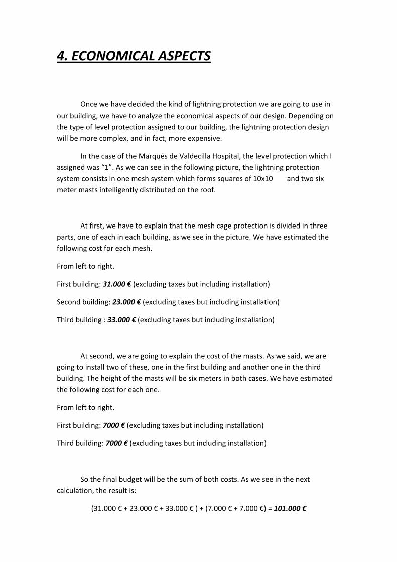
4. ECONOMICAL ASPECTS
Once we have decided the kind of lightning protection we are going to use in our building, we have to analyze the economical aspects of our design. Depending on the type of level protection assigned to our building, the lightning protection design will be more complex, and in fact, more expensive.
In the case of the Marqués de Valdecilla Hospital, the level protection which I assigned was “1”. As we can see in the following picture, the lightning protection system consists in one mesh system which forms squares of 10x10 and two six meter masts intelligently distributed on the roof.
At first, we have to explain that the mesh cage protection is divided in three parts, one of each in each building, as we see in the picture. We have estimated the following cost for each mesh.
From left to right.
First building: 31.000 € (excluding taxes but including installation)
Second building: 23.000 € (excluding taxes but including installation)
Third building : 33.000 € (excluding taxes but including installation)
At second, we are going to explain the cost of the masts. As we said, we are going to install two of these, one in the first building and another one in the third building. The height of the masts will be six meters in both cases. We have estimated the following cost for each one.
From left to right.
First building: 7000 € (excluding taxes but including installation)
Third building: 7000 € (excluding taxes but including installation)
So the final budget will be the sum of both costs. As we see in the next calculation, the result is:
(31.000 € + 23.000 € + 33.000 € ) + (7.000 € + 7.000 €) = 101.000 €

As conclusion we can say that the final budget is quite elevated (although we have to know that the installation is included, which would be an extra cost) but for a hospital is required a high lightning protection level in order to protect the human life and all the very expensive equipment that serve the people and that is essential for day to day.

5.WEBGRAPHY
Lightning, phenomenon:
http://en.wikipedia.org/wiki/Lightning
http://www.allteccorp.com/resources/news/index.php?id=20
http://www.elect.mrt.ac.lk/HV_Chap3.pdf
http://www.indelec.com/foudre/Comprendre_la_foudre/Comprendre_la_foudre.aspx
http://www.aengel.biz/index.php?option=com_content&view=category&id=46&layout=blog&Itemid=55&lang=en
Lightning parameters
http://www.sciencedirect.com/science/article/pii/S0304388609000187
http://www.iclp-centre.org/pdf/Invited-Lecture-3.pdf
History
http://www.lightningsafety.noaa.gov/history.htm
http://www.liebreich.com/LDC/HTML/Various/LightningHistory.html
http://www.public.asu.edu/~gbadams/lightning/lightning.html#history
http://www.indelec.com/foudre/Comprendre_la_foudre/S_en_proteger.aspx
Benjamín Franklin
http://www.ushistory.org/declaration/signers/franklin.htm
http://www.biography.com/people/benjamin-franklin-9301234?page=2
Methods
http://www.dehn.de/pdf/blitzplaner/Chapters/BBP_E_Chapter_05.pdf
http://porsansrl.eurofull.com/imagenes/capitulo_6.pdf
http://www.biel.com.ar/PDF/eventos/segundo_concurso/2_premio_seguridad_electrica.pdf
http://www.dehnargentina.com.ar/seccionesDeInteres/pdf/PUBLICACIONES-ANEXO_ESFERA_RODANTE.pdf
http://hibp.ecse.rpi.edu/~connor/education/Surge/Presentations/Joe%20Crispino%20-%20Surge%20Presentation.pdf
http://www.electro-specialties.com/technical/downloads/Erico%20Technology%20Explained.pdf
http://es.scribd.com/doc/53164168/68/The-protection-angle-method
Lightning damage
http://www.nssl.noaa.gov/primer/lightning/ltg_damage.html
http://science.nasa.gov/science-news/science-at-nasa/1999/essd18jun99_1/
http://en.wikipedia.org/wiki/Brescia
http://disasterhistorian.blogspot.com/2011/07/lightning-strikes.html
http://blogs.static.mentalfloss.com/blogs/archives/21190.html?cnn=yes
Weather
http://www.spainturismo.com/spain/climate.htm
http://foro.tiempo.com/algunos-mapas-de-frecuencia-de-tormentas-t121793.0.html
http://www.divulgameteo.es/uploads/Climatolog%C3%ADa-tormentas.pdf
http://www.tiemposevero.es/formacion/sanzMP04.pdf
http://www.slideshare.net/dowicanfly/estudio-climatico-del-clima-de-santander

Marqués de Valdecilla Hospital
http://es.wikipedia.org/wiki/Hospital_Universitario_Marqu%C3%A9s_de_Valdecilla
http://www.humv.es/ http://www.scsalud.es/atencion_especializada/ficha_hospital.php?Id3=1 http://www.fmdv.org/Es/Paginas/Historia.aspx