lightweight tennis ball pick up & hopper
TRANSCRIPT
Lightweight Tennis Ball Pick Up & Hopper
Final Design Review
June 4, 2018
Team
Pursuit of Hoppiness
By
Tyler Noxon
George DeGrandis
Alejandro Morales
Sponsor
Professor John Chen
Project Advisor
Professor Peter J. Schuster
Mechanical Engineering Department
California Polytechnic State University
San Luis Obispo

Statement of Disclaimer
Since this project is a result of a class assignment, it has been graded and accepted as fulfillment of the course requirements. Acceptance does not imply technical accuracy or reliability. Any use of information in this report is done at the risk of the user. These risks may include catastrophic
failure of the device or infringement of patent or copyright laws. California Polytechnic State University at San Luis Obispo and its staff cannot be held liable for any use or misuse of the
project.

Abstract Within this document, the “Pursuit of Hoppiness” team will clarify some of the details associated with completing this design project. The project is focused on designing a mechanism for tennis
players and coaches of all ages that is able to collect tennis balls around a tennis court, specifically around the net and fence. The goal is to make the final product lightweight, inexpensive, and easy
to use. With multiple ideation sessions, the team was able to brainstorm several ideas that serve the above functions and constraints.
The initial process began with choosing two different ideas that followed through until the beginning of the final phase of our senior project timeframe. The two prototypes were built to
show the functions of gathering and collecting tennis balls. At this point, both prototypes were presented to our sponsor so that as a team, one prototype was chosen to move forward with. The Paddlewheel mechanism was chosen as the final product to build and deliver.
There were multiple tests performed on the Paddlewheel mechanism to ensure the intended goals
were met. This project includes a functionality of a four-bar linkage system that incorporates a locking component that locks the linkage system and bin at different positions. For the second iteration of this project, there will be a cable-locking system implemented on the handle that will
allow the user to pull a smaller handle that will disengage the locking pin for ease of rotating the four-bar linkage system.
Table of Contents
1 Introduction ......................................................................................................................... 1
2 Background .......................................................................................................................... 1 2.1 Interview with Sponsor.................................................................................................................................. 1 2.2 Tennis Club Survey ........................................................................................................................................... 2 2.3 Existing Designs and Patent Research .................................................................................................. 2 2.4 Technical Information .................................................................................................................................... 4
3 Objectives ............................................................................................................................. 5 3.1 Problem Statement ........................................................................................................................................... 5 3.2 Boundary Diagram............................................................................................................................................ 5 3.3 Quality Function Deployment (QFD)...................................................................................................... 5
4 Concept Design Development ........................................................................................... 7 4.1 Concept Development Process and Results ....................................................................................... 7 4.2 Concept Selection Process ............................................................................................................................ 7 4.3 Concept Models and Prototypes................................................................................................................ 9 4.4 Preliminary Analyses ................................................................................................................................... 11
4.4.1 Wind force ........................................................................................................................................................ 11 4.4.2 Force required to lift tennis ball ............................................................................................................. 11 4.4.3 Basket Sizing ................................................................................................................................................... 11 4.4.4 Weather Resistance...................................................................................................................................... 11
4.5 Detailed Description of Selected Concepts ...................................................................................... 12 4.5.1 Belt Drive Mechanism ................................................................................................................................. 12 4.5.2 Paddlewheel Mechanism ........................................................................................................................... 14 4.5.3 Preliminary Plans for Construction ...................................................................................................... 16
5 Final Design ........................................................................................................................ 16 5.1 Prototype Decision ........................................................................................................................................ 16 5.2 Belt Drive Mechanism .................................................................................................................................. 16
5.2.1 Detailed Description of Belt Drive Design.......................................................................................... 17 5.2.2 Analysis Description and Results........................................................................................................... 19 5.2.3 Cost Analysis ................................................................................................................................................... 20 5.2.4 Safety Considerations.................................................................................................................................. 20
5.3 Paddlewheel Mechanism............................................................................................................................ 21 5.3.1 Sub Frame Assembly ................................................................................................................................... 21 5.3.2 Basket and Linkages .................................................................................................................................... 22 5.3.3 Drive Paddle Assembly ............................................................................................................................... 22 5.3.4 Analyses and Results ................................................................................................................................... 23 5.3.5 Safety, Maintenance, and Repair ............................................................................................................ 24 5.3.6 Cost Analysis ................................................................................................................................................... 24
5.4 Paddlewheel Mechanism Design Changes ....................................................................................... 25 5.4.1 Basket Update................................................................................................................................................. 25 5.4.2 Linkage Update .............................................................................................................................................. 26 5.4.3 Structure Update to Sub Frame Assembly and Gathering System Assembly ..................... 27
5.5 Overall Cost Analysis .................................................................................................................................... 27
6 Manufacturing.................................................................................................................... 27 6.1 Belt Drive Mechanism .................................................................................................................................. 28
6.1.1 Procurement ................................................................................................................................................... 28 6.1.2 Manufacturing ................................................................................................................................................ 29 6.1.3 Assembly........................................................................................................................................................... 29
6.2 Paddle Mechanism ......................................................................................................................................... 30 6.2.1 Procurement ................................................................................................................................................... 30 6.2.2 Manufacturing ................................................................................................................................................ 31 6.2.3 Assembly........................................................................................................................................................... 35
7 Design Verification ........................................................................................................... 36 7.1 Paddlewheel Mechanism Tests .............................................................................................................. 36
7.1.1 Ease-of-Use Test ............................................................................................................................................ 36 7.1.2 Transportability Test................................................................................................................................... 37 7.1.3 Linkage Deflection Test .............................................................................................................................. 39 7.1.4 Gathering Efficiency Test........................................................................................................................... 40 7.1.5 Ball Capacity Test .......................................................................................................................................... 41 7.1.6 Challenges and Test Limitations ............................................................................................................ 41
8 Project Management......................................................................................................... 41 8.1 Gantt Chart.......................................................................................................................................................... 42 8.2 Deviations from Original Plan................................................................................................................. 42
8.2.1 Progression to Two Final Prototypes................................................................................................... 42 8.2.2 HDPE Ordering Issue ................................................................................................................................... 42
9 Conclusion .......................................................................................................................... 42 9.1 Next Steps ............................................................................................................................................................ 43
9.1.1 Connecting Hardware Problem .............................................................................................................. 43 9.1.2 Collapsible Handle Problem ..................................................................................................................... 43 9.1.3 Linkage Pin Problem.................................................................................................................................... 43 9.1.4 Tipping Problem ............................................................................................................................................ 44
Appendix A ............................................................................................................................... A-1 Survey: Tennis Ball Hopper Questionnaire................................................................................................... A-1 List of Customer Wants/Needs ............................................................................................................................. A-2 Different Tennis Ball Hopper Designs .............................................................................................................. A-2
Appendix B ............................................................................................................................... B-1 QFD: House of Quality ................................................................................................................................................ B-1
Appendix C .................................................................................................................................C-1 Ideation Session Notes and Decision Matrices .............................................................................................C-1
Appendix D ............................................................................................................................... D-1 Preliminary Analyses ................................................................................................................................................. D-1
Appendix E .................................................................................................................................E-1 Concept Layout Drawings .........................................................................................................................................E-1
Appendix F .................................................................................................................................F-1 Complete Drawing Package for Belt Drive Model....................................................................................... F-1 Complete Drawing Package for Paddlewheel Model ............................................................................. F-10
Appendix G ............................................................................................................................... G-1 Purchased Parts Details............................................................................................................................................ G-1
Appendix H ............................................................................................................................... H-1

Budget/Procurement List........................................................................................................................................ H-1
Appendix I.................................................................................................................................. I-1 Final Analyses Calculations ...................................................................................................................................... I-1
Appendix J...................................................................................................................................J-1 Safety Hazard Checklist/FMEA ............................................................................................................................... J-1
Appendix K ............................................................................................................................... K-1 Design Verification Plan and Results Table (DVP&R)............................................................................. K-1
Appendix L .................................................................................................................................L-1 Operators' Manual ........................................................................................................................................................ L-1
Appendix M.............................................................................................................................. M-1 Gantt Charts .................................................................................................................................................................... M-1
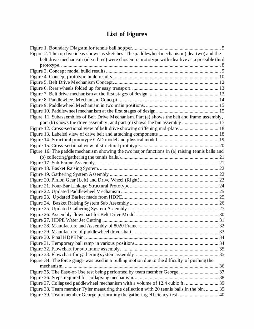
List of Figures
Figure 1. Boundary Diagram for tennis ball hopper. ...................................................................... 5 Figure 2. The top five ideas shown as sketches. The paddlewheel mechanism (idea two) and the
belt drive mechanism (idea three) were chosen to prototype with idea five as a possible third prototype. ................................................................................................................................ 8
Figure 3. Concept model build results. ........................................................................................... 9 Figure 4. Concept prototype build results. .................................................................................... 10 Figure 5. Belt Drive Mechanism Concept. ................................................................................... 12
Figure 6. Rear wheels folded up for easy transport. ..................................................................... 13 Figure 7. Belt drive mechanism at the first stages of design. ....................................................... 13
Figure 8. Paddlewheel Mechanism Concept................................................................................. 14 Figure 9. Paddlewheel Mechanism in two main positions. .......................................................... 15 Figure 10. Paddlewheel mechanism at the first stages of design. ................................................. 15
Figure 11. Subassemblies of Belt Drive Mechanism. Part (a) shows the belt and frame assembly, part (b) shows the drive assembly, and part (c) shows the bin assembly ............................. 17
Figure 12. Cross-sectional view of belt drive showing stiffening mid-plate. ............................... 18 Figure 13. Labeled view of drive belt and attaching components ................................................ 18 Figure 14. Structural prototype CAD model and physical model ................................................ 19
Figure 15. Cross-sectional view of structural prototype ............................................................... 20 Figure 16. The paddle mechanism showing the two major functions in (a) raising tennis balls and
(b) collecting/gathering the tennis balls.\ .............................................................................. 21 Figure 17. Sub Frame Assembly................................................................................................... 21 Figure 18. Basket Raising System. ............................................................................................... 22
Figure 19. Gathering System Assembly ....................................................................................... 22 Figure 20. Pinion Gear (Left) and Drive Wheel (Right)............................................................... 23
Figure 21. Four-Bar Linkage Structural Prototype ....................................................................... 24 Figure 22. Updated Paddlewheel Mechanism .............................................................................. 25 Figure 23. Updated Basket made from HDPE. ............................................................................ 25
Figure 24. Basket Raising System Sub Assembly ....................................................................... 26 Figure 25. Updated Gathering System Assembly ......................................................................... 27
Figure 26. Assembly flowchart for Belt Drive Model. ................................................................. 30 Figure 27. HDPE Water Jet Cutting ............................................................................................. 31 Figure 28. Manufacture and Assembly of 8020 Frame. ............................................................... 32
Figure 29. Manufacture of paddlewheel drive shaft. .................................................................... 33 Figure 30. Final HDPE bin. .......................................................................................................... 34
Figure 31. Temporary ball ramp in various positions. .................................................................. 34 Figure 32. Flowchart for sub frame assembly. ............................................................................. 35 Figure 33. Flowchart for gathering system assembly. .................................................................. 35
Figure 34. The force gauge was used in a pulling motion due to the difficulty of pushing the mechanism. ........................................................................................................................... 36
Figure 35. The Ease-of-Use test being performed by team member George. .............................. 37 Figure 36. Steps required for collapsing mechanism. ................................................................... 38 Figure 37. Collapsed paddlewheel mechanism with a volume of 12.4 cubic ft. .......................... 39
Figure 38. Team member Tyler measuring the deflection with 20 tennis balls in the bin. .......... 39 Figure 39. Team member George performing the gathering efficiency test................................. 40

List of Tables
Table 1. Benchmarking of current products.................................................................................... 3 Table 2. Patent search related to tennis ball hoppers. ..................................................................... 3
Table 3. Specifications table for the tennis ball hopper. ................................................................. 6 Table 4. Purchased parts from McMaster-Carr with costs. .......................................................... 28
Table 5. McMaster-Carr Parts....................................................................................................... 31 Table 6. The forces recorded during the ease-of-use test including the number of balls jammed or
overshot in parentheses during each trial. ............................................................................. 37
Table 7. Linkage deflection data collected ................................................................................... 40 Table 8. Gathering efficiency data collected. ............................................................................... 41

1
1 Introduction
Professor John Chen at Cal Poly introduced the problem of designing a lightweight tennis ball
pick-up and hopper. Although other solutions currently exist to solve this problem, they are either too expensive, too hard to use, or too bulky. Some research on the alternative solutions can be
found in the Background Section. Some of the more general goals of this project are discussed below. First, team members want to design a product that solves all the needs of our customers. This includes both our sponsor, Dr. Chen, as well as other tennis players of varying ages. Once
this goal is met, team members can also focus on secondary goals like designing a good-looking, innovative design that would make customers focus on the elegance of the product even when it
does such a simple task. The background section will demonstrate the research that has been done towards a solution. This
includes notes on an interview with the sponsor, some customer research into existing designs, a patent search, and some technical research pertaining to the subject. Next, in the Objectives
section, the scope of the problem will be assessed. This will include various techniques including a defined problem statement, a boundary diagram, and a QFD table. The concept design development section shows our decision process and its final results. This will include the concept
selection process, as well as some preliminary analyses on the chosen designs. At the end of this section, the two prototyped ideas will be described in depth. After this section is the Final Design
section, where the final prototypes of both the belt drive and the paddlewheel mechanisms are described in depth. This section will also describe the selection process where our two final prototypes were narrowed down to one final design. The Manufacturing section will discuss all of
the manufacturing techniques used to construct both final prototypes. Next, the Design Verification section will describe and list the results of the five tests ran on the prototype of our
final design. In the Project Management section, the overall design process of the project will be investigated. This will include showing some of the key deliverables using a Gantt chart, and some of the special techniques that will be used to solve the problem. Finally, the conclusion will
summarize the document and propose some future changes to the mechanism.
2 Background
The research done by the team was focused on the customer wants and needs. The team created a survey with specific questions that were tailored to our problem definition. This survey aided the
direction on what functions and aspects were most important in our design. The research also includes existing patents and technical information that is in more detail below.
2.1 Interview with Sponsor To better understand the scope of the project, a meeting was conducted with our sponsor and potential customer, Professor Chen. Currently, Professor Chen owns a Wilson Tennis Ball Hopper
as seen in Figure A.1. The current problems he has encountered with it are that the welds are beginning to break apart after less than two years of use, the hopper itself is too heavy for his 5-year old son to use, and the hopper is not comfortable to carry around. Professor Chen has

2
emphasized the need for a better mechanism for tennis players to use with ease that is low-cost, durable, and with no electronic devices.
2.2 Tennis Club Survey To obtain additional information on the importance of different design criteria, a survey was sent to the Cal Poly Tennis Club. The survey received 17 responses from club members and the results
were implemented into the Quality Function Deployment Document. The survey questions and general responses can be seen in Appendix A. From conducting this survey, the most important design criteria to the players were mobility, durability , and ease of use. The least important criteria
were it being comfortable, adjustable, and inexpensive. The average number of balls that the players wanted to carry was about 75 balls. In the comments from the questionnaire about issues
with current designs, most players indicated that they break easily, are heavy, flimsy, and hard to transport. In the comments regarding things that the players wished they had, the players indicated that they wanted it lightweight, able to store tennis balls, able to change from a hopper to a stand,
and more stable.
2.3 Existing Designs and Patent Research As a part of the background research, existing products were examined and rated on a scale from
1 (poor) to 5 (great) in terms of their performance in each of the categories listed in Table 1. The categories of Table 1 were generated based off our sponsor list of wants, as well as other aspects that the team deemed important. The benchmarking of these products allowed us to determine
what methods of tennis ball collecting were the most effective and allowed the team to understand who the main competitors are. From the products we benchmarked, the Kollectaball CS60 (item
4) and Tomohopper (item 8) stood out the most due to the overall unweighted score, as well as the technologies employed. The Kollectaball CS60 converts into a ball holder after collection and has small metal wires that allow the tennis balls to roll into the main cavity during collection. The
Tomohopper is a rolling ball collector that allows for ball collecting along the fence and net due to its arm shape. It picks up the balls in grooves in the wheels and deposits them into a main
collector bin. After collecting the tennis balls, the bin can be mounted higher up to serve as a ball stand. Photos of these products can be seen in Appendix A.
3
Table 1. Benchmarking of current products.
Wilson
Tennis
Hopper
Har-Tru
Ball Mower
Roller
Mower
Kollect-
aball
Multi-
mower
Rapid
Ball
Boy
Hill
Hopper
Tomo-
hopper
Brad
Tennis
Ball
Retriever
Carry Enough
Tennis Balls 5 5 5 4 5 5 5 5 5
Light Weight 5 1 4 4 2 1 1 3 3
Durable 1 4 1 2 5 2 5 5 5
Mobile (to and from
the car) 5 1 3 5 3 2 1 4 3
Inexpensive 5 2 4 4 3 1 1 3 4
Easy to use 2 4 3 3 4 5 1 4 3
Comfortable 1 2 2 3 1 2 1 4 3
Purely Mechanical 5 5 5 5 5 5 5 5 5
Adjustable 1 1 4 4 1 1 1 1 1
While conducting background research, a patent search was done to see what kinds of solutions
had been patented. During this research, five separate patented ideas were examined to learn about the competition as well as find some promising attributes that could be included in the final design. Since this is a problem with a wide variety of solutions, many patents exist that would solve the
problem. However, the four patents chosen represented very different and innovative ways of solving the problem. A table of the four patents examined can be seen in Table 2.
Table 2. Patent search related to tennis ball hoppers.
Patent Name Patent Number Key Characteristics
Tennis Ball
Retrieving Storage Container
US 4412697 A Similar wire frame as common solution
Handles adapt to form stand, acts as lifted storage
Tennis Ball Retriever and Storage Cart
US 5301991 A Rolling unit, pushed with horizontal bar
Hopper is in between two wheels
Picks up balls with curved wireframe Tennis Ball Retrieval
Cart and Practice Hopper
US 7341294 B2 Rolling unit, pushed with horizontal bar
Has arms to guide balls before pick-up
Balls picked up by wheel spokes
Tennis Ball Collection,
Dispensing, and Transport Apparatus
US 20060068948 A1 Rolling unit, pushed with single diagonal bar (adjustable)
Uses paddlewheel motion to pick-up
This patent search was conducted using Google Patent Search. In the case of the first two patents on the table, these were issued over 20 years ago and since have expired. As a result, all manufacturers are now able to manufacture and sell these products. The next patent on the list is

4
still active today and poses a unique solution to our problem. In this patent design, arms and slots guide the tennis balls into the spokes of the wheels used to drive the mechanism. Then, as the
wheels spin, the balls are lifted into a bin. In the fourth and final patent of Table 2, a paddlewheel like one of our designs picks up balls and spits them into a basket. However, this patent was
abandoned, and thus the idea is still available for production today. This abandonment could have been a result of an inability to reply to the patent office within a given time period, or through a formal expression of abandonment by the applicant. [1] Regardless of the reason for abandonment,
this idea is still available for production today. Similarly, there are other situations in which spherical objects need to be lifted from the ground. For example, there is a product called “Bag
Shag” that can lift golf balls from the ground. It is a product that is simply a tube that has a bag attached. The user utilizes this product by pushing down on any golf ball with the tube and the golf balls are pushed upwards until the bag attached is full.
It is important to recognize that while there are many solutions to the problem we are looking to
solve, not all of them have progressed to the patent stage. With this in mind, the team will look to create as many different design iterations as possible while still early in the design phase. This will result in lots of prototyping and testing, providing the team with ample amounts of applicable data
about the product. Once as much data as possible is collected, then the best solution can be chosen from the different prototypes and that solution may be able to advance to the patent stage.
2.4 Technical Information In order to learn more about tennis balls, some research was conducted to be sure that we are not adding any additional problems to the functionality of the tennis ball. According to the leading authority in the tennis world, the International Tennis Federation (ITF), tennis balls must be within
an approved range of diameter. This range is 2.57-2.70 in. [2] In addition to having a regulated diameter, tennis balls also have a regulated outer surface of felt-covered rubber. This rough surface
is used to trip the boundary layer in order to reduce the drag on the ball during flight. [3] Another aspect of the tennis ball research was determining why some storage containers for tennis
balls are pressurized. Since the inside of a tennis ball is pressurized to approximately twice atmospheric pressure to preserve its bouncy quality, as soon as the ball is exposed to the
atmosphere, it begins to move towards pressure equilibrium and depressurize as it degrades. As a result, some storage containers are pressurized in order to reduce the leakage from the ball and allow them to last longer.
The lifetime of the tennis ball can pose some relatively unforeseen consequences due to the number
of balls made per year (~325 million), and the fact that these balls are composed of not easily biodegradable rubber. [4] With this information in mind, the Pursuit of Hoppiness team has considered using a pressurized storage container to hold the balls for the tennis hopper. With the
use of this pressurized container, the product would not only perform the task of picking up tennis balls, but it would also be able to increase the life of the balls by preventing leakage and
maintaining the balls’ bounciness.

5
3 Objectives
To fully understand the overall design, the team created a boundary diagram as well as a Quality
Function Deployment (QFD) plan. The QFD is shown in Appendix B.
3.1 Problem Statement Tennis players and coaches of all ages need a way of picking up tennis balls on the court, specifically around the net and the fence. This solution will double as a holder and will transport
the balls to and from the court. The mechanism will be easy-to-use, lightweight, and inexpensive by employing a novel mechanical means.
3.2 Boundary Diagram
Figure 1. Boundary Diagram for tennis ball hopper.
To further understand the scope of this project, a Boundary Diagram was also created and is seen in Figure 1. The Boundary Diagram explains where the boundaries of the product are, and what
outside references will play key roles in the development of the design. As seen in Figure 1, the external references that will play a part in our design decisions are the tennis court, the vehicle
trunk, the player, and of course the tennis balls. The court plays a part because the design will have to maneuver within its bounds while performing and will have to interface with the net and fence. The car trunk will help define the size restrictions on our design so that we can be sure that it will
be easily mobile in a variety of different vehicles. Also, the person plays a part because this product will be designed to be human powered and we will need to design according to the power output
of people of all ages and sizes.
3.3 Quality Function Deployment (QFD) The Quality Function Deployment process determined what specifications were needed for the new tennis hopper. Initially, research was done on existing products so that the needs and wants
of the customers can be weighted. The team then created a list of targets that our product should achieve and weighted those targets to existing products. The specifications were then determined
by the customer requirements. Parameters that reflected the customers’ needs such as the hopper being lightweight, durable and inexpensive, were taken into consideration. Each specification was rated in terms of importance from 1-5 (i.e. 1-not important 5-extremely important). A full list of

6
the customer wants and needs is included in Appendix A. The House of Quality was developed after the QFD process and is included in Appendix B.
Table 3 is a specifications table that includes descriptions of parameters for the tennis ball hopper.
A specification includes the requirements or targets that the overall design needs to meet. For example, the overall design is to be inexpensive so our goal is to design a mechanism within the range of $100-$200 USD.
Table 3. Specifications table for the tennis ball hopper.
Spec.# Parameter Description Requirement or
Target Tolerance Risk Compliance
1 Carry Enough Tennis Balls 48 balls +50/-12 L A, T 2 Light Weight 6-10 lbs +10-15 lbs H I
3 Mobile Fit in small trunk N/A M A, I, T 4 Inexpensive $100-$200 +$200/-$50 H A
5 Easy-To-Use Pass/Fail N/A M A, I, T, S 6 Comfortable N/A N/A M A, T
7 Durable 5 years N/A L S 8 Purely Mechanical Pass/Fail N/A M A, I, T
9 Adjustable 5% F to 95% M N/A L A, T
Table 3 is a specifications table that includes a compliance column. The methods included are Analysis (A), Test (T), Similarity to Existing Designs (S), and Inspection (I). Each compliance
method was determined based on the parameter descriptions. For the testing and analysis, our group will need a prototype to check whether it meet those specifications. The risk specifications were assigned with High (H), Medium (M), and Low (L) risk factors. The following describes
each specification and its importance:
1) Specification 1 is important when designing our product because the mechanism needs to be able to hold a certain number of tennis balls so that the use is efficient for the customers. This will be measured in terms of length, width, and height because our overall goal is to
have a container that will collect the tennis balls. 2) The light weight description is important because the team wants the final product to be
operated by customers of all ages. This specification was assigned as a high risk because the requirement or target for the product is set to be a limited weight.
3) Mobility is a key specification because it allows the customer to use a mechanism that can
be easily maneuvered to and from the court. 4) To satisfy all customers, we want to make sure that the overall product is inexpensive.
This will be achieved by the type of selected material for all hardware and main body of the mechanism.
5) As for any other product, customers want mechanisms to be easy-to-use. This is important
because it will allow all customers of all ages to use something that is universal. 6) A comfortable mechanism in terms of usage and storage is important because it allows the
users to not hassle and struggle with a product that is intended to be used with ease. 7) Durability is also a critical specification because we want customers to get a product that
is worth the purchase. We are aiming for a target of at least five years, and since our time

7
frame for this project does not allow us to test that, we can estimate the lifespan of other products that will potentially use the same materials and parts.
8) Having a purely mechanical system is one of the main goals of this project. It is important because this specification falls into the category of customer wants.
9) Adjustability will allow users of different heights to use the mechanism with ease. The constraint of different heights will be removed by adding a system that will adjust to said user.
These specifications were determined from a survey that was sent out to a tennis team and other
tennis players. In addition, in order to create the most appealing product for the customer, the cost was also deemed to be a high-risk specification. To deal with the high-risk specifications throughout the design, the team will consider simplicity of design as the top priority. With fewer
and less complicated parts, the solution will not only be cheaper to manufacture, but also lighter.
4 Concept Design Development
The design process began with us conducting a function decomposition of our mechanism so that we could identify the three primary functions of the device. From this, we determined that our
three main functions were gathering, lifting, and transporting the tennis balls. With these functions in mind, we conducted several ideation sessions to generate ideas for each function. Once the team
had several ideas for multiple functions, a few conceptual models were built to get some feedback on how these ideas would function on an actual prototype. Pugh matrices were then developed by each team member for the three critical functions which were then combined in a morphological
matrix to develop complete system concepts. These concepts were then put into a weighted decision matrix, scored based on how they related to our design criteria, and then the highest
scoring concepts were turned into concept prototypes.
4.1 Concept Development Process and Results Several ideation sessions were conducted that focused on the major and secondary functions as well as an overall mechanism. The first ideation session consisted of brainstorming ideas that
would include any possible way that can make such a mechanism functional. Such ideas include: use of Velcro belt to scoop up tennis balls, a vacuum suction mechanism, half-circular wire frame,
and spinning wheels to raise the tennis balls. The second ideation session was focused on one specific function: storing tennis balls. The ideas from this session include: a slotted box that allows the tennis balls to enter from the side, storing tennis balls in basket that can raise to waist height,
and storing tennis balls in a bag that is connected to the mechanism. Ideation session number three consisted of ideas for the function of raising tennis balls. Some ideas from this session include: a
scissor-like basket that can raise to a desired height by connected linkages, wedged wheels that have slots for the tennis balls that raise as the mechanism is pushed, and a crank wheel that is raised manually by the user. The last ideation session focused on the function of transporting tennis
balls to and from the court. During this session, we wanted to focus on how we can create a product that was able to fit in a car and be comfortable to transport to and from the court.
4.2 Concept Selection Process To narrow down our list of ideas to a select few possible concepts, we began by evaluating our ideas based on their feasibility. After this initial feasibility check, we then moved on to the

8
development of Pugh Matrices for each of our three main functions: transport to and from the tennis court, gathering the tennis balls, and lifting the tennis balls to a comfortable height. The
Pugh Matrices compare different concepts to a single datum and can either be given a +, -, or S (same) with regards to how they compare to the chosen datum design. For these three different
matrices, we used the Tomohopper as the datum, which can be seen in Appendix A. Once we determined which concepts from each function’s Pugh Matrices were the best options, we then combined these stronger concepts in a morphological matrix to create full designs that satisfy the
customers’ requirements. We decided on five full designs from the morphological matrix and used a weighted decision matrix to determine which design would be the highest weighted so that we
can move forward and begin prototyping. These five designs can be seen in Figure 2.
(a) Idea one showing the
three combined functions of transporting, gathering, and
lifting.
(b) Idea two is our
paddlewheel mechanism that shows all the critical
functions.
(c) Idea three is our belt drive
mechanism and is the highest weighted in the decision
matrix.
(d) Idea four showing four
combined functions using the morphological matrix.
(e) Idea five is our potential
third prototype and shows three functions from our
ideations sessions.
Figure 2. The top five ideas shown as sketches. The paddlewheel mechanism (idea two) and the belt drive mechanism (idea three) were chosen to prototype with idea five as a possible third
prototype.
Since our project is straightforward and not heavily dependent on analysis, we decided that
building two or three prototypes would be possible. From the decision matrix, there were three other designs that were equally weighed. We decided to build the belt drive mechanism, which
was our highest weighted design, and the paddlewheel mechanism. The third possible prototype we will build will be a scissor-like basket that will raise by connected linkages. The Pugh Matrices, the morphological matrix, and the weighted decision matrix are shown in Appendix C.
9
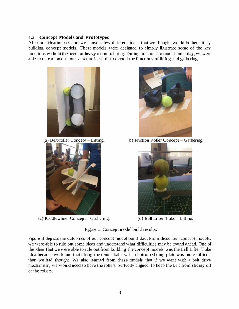
4.3 Concept Models and Prototypes After our ideation session, we chose a few different ideas that we thought would be benefit by building concept models. These models were designed to simply illustrate some of the key
functions without the need for heavy manufacturing. During our concept model build day, we were able to take a look at four separate ideas that covered the functions of lifting and gathering.
(a) Belt-roller Concept – Lifting. (b) Friction Roller Concept – Gathering.
(c) Paddlewheel Concept – Gathering. (d) Ball Lifter Tube – Lifting.
Figure 3. Concept model build results.
Figure 3 depicts the outcomes of our concept model build day. From these four concept models,
we were able to rule out some ideas and understand what difficulties may be found ahead. One of the ideas that we were able to rule out from building the concept models was the Ball Lifter Tube Idea because we found that lifting the tennis balls with a bottom sliding plate was more difficult
than we had thought. We also learned from these models that if we went with a belt drive mechanism, we would need to have the rollers perfectly aligned to keep the belt from sliding off
of the rollers.

10
After building our concept models and completing the matrices discussed above, we narrowed down our options and moved on to develop conceptual prototypes to get a first look at how some
of these concepts might function on a large scale. For our concept prototypes, we focused on two major functions for gathering and lifting: the paddlewheel mechanism and the belt drive
mechanism. These two functions were key components to our overall design concepts that scored the highest on our weighted matrix. Figure 4 depicts the concept prototypes that we built for the testing of these functions.
(a) Paddlewheel mechanism concept prototype.
(b) Belt drive mechanism concept prototype.
Figure 4. Concept prototype build results.
Although these concept prototypes were not fully functioning mechanisms, they provided us with valuable information that is crucial to the concepts moving forward. For the paddlewheel mechanism, we realized that the roller will more than likely must be larger so that the balls can
make it into our basket. Also, we found that this design can sometimes get caught up on tennis balls if it does not encounter them at the right location. For the belt drive mechanism, we observed
that as the belt loses tension, it becomes ineffective at lifting the tennis balls. This is a major problem that would need to be corrected with an adequate belt or belt tensioner to keep the belt taught. We also learned that with the wheels directly driving the belt, it takes a long time for the
balls to get from the ground to the top of the channel. This is a problem that we can solve by separating the belt rollers from the wheels and adding gearing to allow the belt to rotate faster.
11
4.4 Preliminary Analyses Some preliminary analyses were conducted in order to highlight some additional design challenges for our final design. By looking at some of the loads that will act on our designed mechanism, we
had the opportunity to see additional features that might be needed for the design to be feasible. Hand calculations for this analysis can be seen in Appendix D. Also, some of the analyses focused
on certain things we need to watch out for to increase the life of the product.
4.4.1 Wind force An analysis of the drag forces due to wind was conducted on our chosen concepts. Since the belt
drive mechanism has the largest surface area exposed to wind, this design would be exposed to the largest wind loads. After an analysis of the drag on our belt drive mechanism, it was determined
that the maximum wind load that this device would experience under a 60-mph wind would be 41.5 lb. Not only would this wind force oppose the force used to push the mechanism, but it would also cause the belt drive to be pushed all over the court even when the user wanted it stationary.
Since a wind load this large would present significant problems, some steps must be taken in our design to alleviate this problem. First of all, our team intends to include wheel locks that will lock
the mechanism in place to prevent unwanted movement. Additionally, a smaller belt could be used in order to lower the wind force, or a belt that allows air to pass through it.
4.4.2 Force required to lift tennis ball According to the ITF, the acceptable mass of a tennis ball is a range of 56.0-59.4 grams.i With this parameter in mind, the total weight of 72 tennis balls is around 10 pounds. This chosen tennis ball
number comes from the fact that a large case of balls contains 72 tennis balls. Estimating the weight of the basket to be around 5 pounds, the total lifting force required to lift a full basket of balls will be around 15 pounds.
4.4.3 Basket Sizing Another calculation was done in order to find the minimum possible size for our basket. In order
to fit our maximum carrying capacity of 72 tennis balls, a basket or bin with a volume of at least 0.322 ft2 must be used. However, in order to account for vibrations or the bounciness of the tennis
balls, a safety factor will be applied to this volume in order to find the volume for our final basket.
4.4.4 Weather Resistance An additional analysis was conducted to determine what effects the weather could have on the life
of our design. Because the tennis ball hopper will be used throughout the year, it will need to be able to function in all types of weather conditions, including heavy exposure to moisture and
temperature changes. We initially examined different materials that we could use for structural parts to be sure that corrosion was kept to a minimum to promote longevity of the device. Some materials that we are considering are stainless steel, aluminum alloys, carbon steel, and some
plastics such UV stabilized HDPE (high density polyethylene). The advantage of using the stainless steel is that it has a high percentage of chromium that creates a protective barrier against
corrosion. Additionally, aluminum has a similar mechanism in the formation of aluminum oxide which protects the metal from the outside environment and will happen naturally, or through the anodizing process. If we decided to use plain carbon steel, we will have to be sure that the metal
is covered in a protective paint or coating that will keep the iron from oxidizing and forming rust

12
on the product. If we decide to go the route that uses HDPE for structure rather than metal, we can decrease weight and still maintain high weather resistance. If we do decide to use a metal, we will
need to make sure that there is no induced galvanic corrosion due to moisture, at least two dissimilar metals, and direct metal to metal contact. Some ways to circumvent this is to use rubber
or nylon washers to separate the two materials when fastening, also, if the surface area difference between the two metals is great, then the effect of galvanic corrosion will be negligible. [5]
4.5 Detailed Description of Selected Concepts There are our two main concepts that were selected and built as prototypes. Our first chosen
concept is the paddlewheel mechanism and our second chosen concept is the belt drive mechanism. These two main concepts are the ideas that we thought had the most potential to fulfill the needs
of our customers.
4.5.1 Belt Drive Mechanism
Figure 5. Belt Drive Mechanism Concept.
The belt drive mechanism, shown in Figure 5, utilizes a large belt to transport the balls up a surface to a desired height for ease of handling while playing tennis. The belt is driven from the rotation of the wheels so that as the device operates by rolling around the court, and the lifting of tennis
balls occurs simultaneously. The purpose of this design is so that the user does not need to lift the basket of tennis balls from a lower position to a desired height which negates the issue of the basket
being too heavy to carry. The back surface will have a curved surface over the top of the belt that will direct the tennis balls into the basket mounted on the front. The overall size and dimensions of this concept are similar to our first concept, and rough dimensions can be found in Appendix E.
13
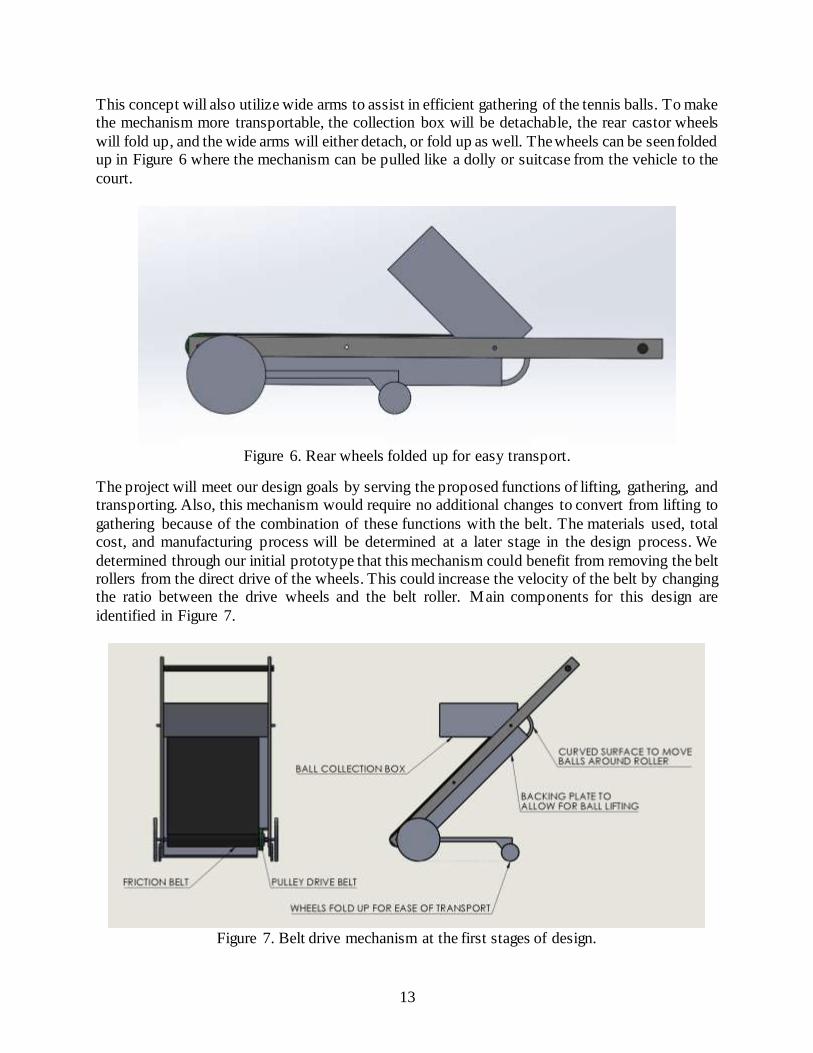
This concept will also utilize wide arms to assist in efficient gathering of the tennis balls. To make the mechanism more transportable, the collection box will be detachable, the rear castor wheels
will fold up, and the wide arms will either detach, or fold up as well. The wheels can be seen folded up in Figure 6 where the mechanism can be pulled like a dolly or suitcase from the vehicle to the
court.
Figure 6. Rear wheels folded up for easy transport.
The project will meet our design goals by serving the proposed functions of lifting, gathering, and transporting. Also, this mechanism would require no additional changes to convert from lifting to
gathering because of the combination of these functions with the belt. The materials used, total cost, and manufacturing process will be determined at a later stage in the design process. We
determined through our initial prototype that this mechanism could benefit from removing the belt rollers from the direct drive of the wheels. This could increase the velocity of the belt by changing the ratio between the drive wheels and the belt roller. Main components for this design are
identified in Figure 7.
Figure 7. Belt drive mechanism at the first stages of design.
14
There are a few hazards or risks that come with both chosen concepts that need to be addressed.
First, the mechanisms both have rolling and revolving actions. The plan for the belt and the paddlewheel is to cover them both with either a plastic casing or thin sheet metal. Since the belt
and paddlewheel will be revolving, there are potential risks in pinch points which will be addressed with the casing on both systems. Second, the mechanisms are designed to carry tennis balls in a basket at certain heights, so the potential of tipping is possible. To correct this possible problem,
analysis on tipping and wind loads will be determined and incorporated in the final products. Additional calculations on tipping and wind loads can be found in Appendix D. An additional risk
for the belt drive mechanism is the tension in the belt. If the belt becomes to slack, it will not be able to lift the balls effectively, and they may fall back down to the ground. For the belt drive mechanism, one current unknown is the method for transferring the tennis balls from the ground
to the belt to be lifted. In our concept prototype, we were not able to test this out but it will be one of our next tests to be sure that this is feasible.
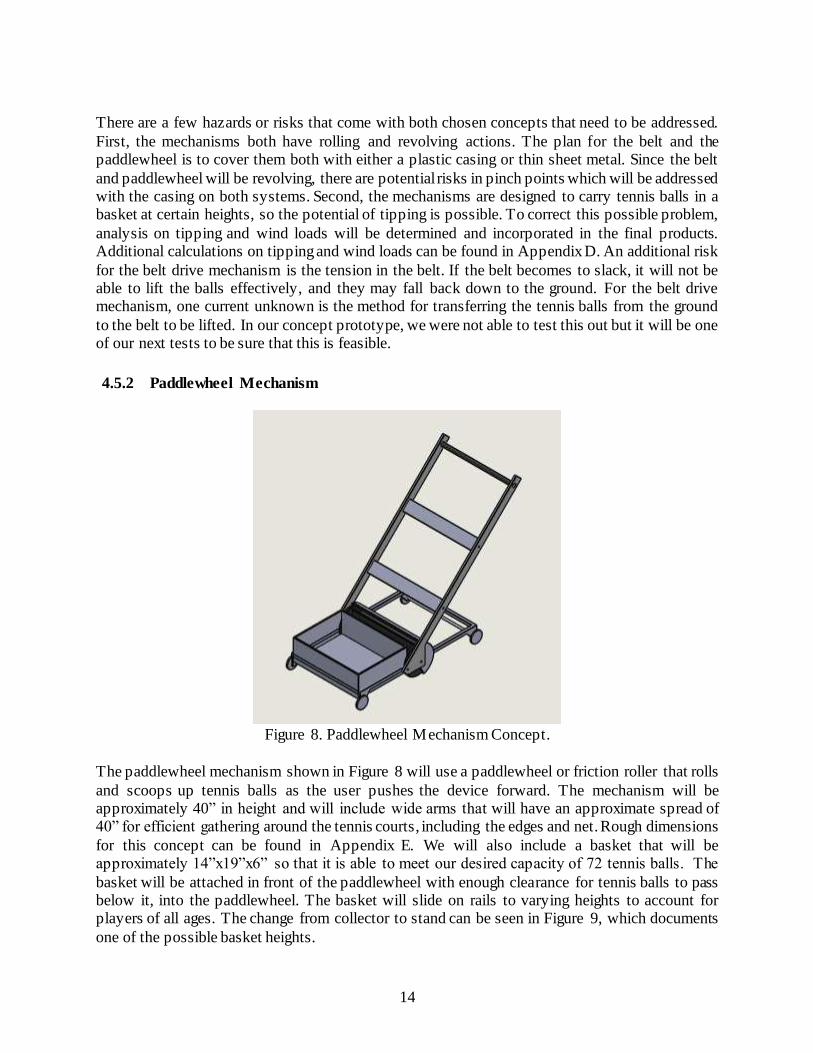
4.5.2 Paddlewheel Mechanism
Figure 8. Paddlewheel Mechanism Concept.
The paddlewheel mechanism shown in Figure 8 will use a paddlewheel or friction roller that rolls
and scoops up tennis balls as the user pushes the device forward. The mechanism will be approximately 40” in height and will include wide arms that will have an approximate spread of 40” for efficient gathering around the tennis courts, including the edges and net. Rough dimensions
for this concept can be found in Appendix E. We will also include a basket that will be approximately 14”x19”x6” so that it is able to meet our desired capacity of 72 tennis balls. The
basket will be attached in front of the paddlewheel with enough clearance for tennis balls to pass below it, into the paddlewheel. The basket will slide on rails to varying heights to account for players of all ages. The change from collector to stand can be seen in Figure 9, which documents
one of the possible basket heights.

15
(a) Concept in Collector Position. (b) Concept in Stand Position.
Figure 9. Paddlewheel Mechanism in two main positions.
For the paddlewheel to pick up tennis balls, a backing plate is required to keep the balls in the slots while rotating. The paddlewheel backing plate will most likely be made from a semi-flexible
plastic or thin sheet metal and can be seen in Figures 9a and 9b. This design will also implement castor wheels so that the mechanism will be able to maneuver the court with ease. For ease of transport, the basket will be removable and the castor wheels will fold up so the mechanism can
have a smaller footprint in the vehicle, and so it will be easy to roll to the court.
Figure 10. Paddlewheel mechanism at the first stages of design.
This concept will be able to meet our project goals because it will be easy to use, lightweight and simple. It will meet our ball capacity and hopefully it will be within our designated price range.
This design considers our three main functions and provides flexibility in basket height. The cost

16
and materials will be determined during our second stage of building a structural prototype. This concept is straight forward, however, there is some risk associated with the basket lifting and
getting the balls into the basket. The current design has the basket slide on rails to different heights, but we are also considering ways to automate this process. Through automation, the customer will
not have to lift the basket to the desired height. This is a current unknown that we will continue to research to find an elegant solution. The other risk we have is getting the balls all the way into the basket. Because the tennis balls need to pass underneath the collection box, the box sits higher and
is more difficult to get balls into. We are testing ways to solve this issue by incorporating a ball buffer that will overflow into the collection box.
4.5.3 Preliminary Plans for Construction
Our preliminary plans for construction are to first find materials and processes that will be the same or similar to what is used on our actual concept prototype. Additionally, we will continue to
search for components that do not need to be manufactured to keep our total costs down. Once we determine what materials will be chosen to proceed with our design, we will build a structural
prototype and begin the testing phase. As mentioned above, we plan on testing a minimum of two designs including the belt drive mechanism and the paddlewheel mechanism.
5 Final Design
The selection of a final design for this project was slightly different from other senior projects. The
Prototype Decision section will talk about exactly why the decision was made to choose the final design from our two concepts. However, since this decision came after the critical design review,
this chapter will contain the description of both the belt drive and the paddlewheel mechanisms.
5.1 Prototype Decision After completing the manufacturing for both prototypes, we were able to narrow down our project direction after consulting with our sponsor, Dr. Chen, with our thoughts of the prototypes. We
ultimately decided to go with the paddlewheel mechanism over the belt drive mechanism. After doing some preliminary testing with both prototypes, we found that the drive belt for the belt was beginning to slip and not transfer energy efficiently. This was a major issue as it would halt the
rotation of the belt, stopping the mechanism from functioning correctly. In addition to this, we found the belt drive mechanism harder to maneuver and more difficult to modify into a more
compact solution. With this decision made, we began to modify the paddle mechanism to address issues that we encountered during our first build. As a result of this decision, this chapter will define the functionality of both prototypes, but the description of the paddlewheel mechanism will
go into much more depth.
5.2 Belt Drive Mechanism The Belt Drive Mechanism was our first prototype that will be discussed briefly in this section.
Furthermore, the drawing package for the Belt Drive Mechanism at the time of the critical design review is included in Appendix F.
17
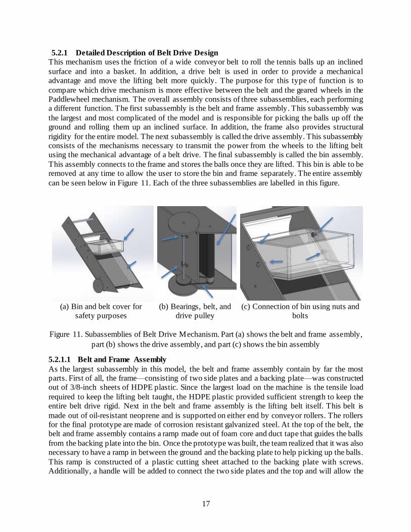
5.2.1 Detailed Description of Belt Drive Design
This mechanism uses the friction of a wide conveyor belt to roll the tennis balls up an inclined
surface and into a basket. In addition, a drive belt is used in order to provide a mechanical advantage and move the lifting belt more quickly. The purpose for this type of function is to
compare which drive mechanism is more effective between the belt and the geared wheels in the Paddlewheel mechanism. The overall assembly consists of three subassemblies, each performing a different function. The first subassembly is the belt and frame assembly. This subassembly was
the largest and most complicated of the model and is responsible for picking the balls up off the ground and rolling them up an inclined surface. In addition, the frame also provides structural
rigidity for the entire model. The next subassembly is called the drive assembly. This subassembly consists of the mechanisms necessary to transmit the power from the wheels to the lifting belt using the mechanical advantage of a belt drive. The final subassembly is called the bin assembly.
This assembly connects to the frame and stores the balls once they are lifted. This bin is able to be removed at any time to allow the user to store the bin and frame separately. The entire assembly
can be seen below in Figure 11. Each of the three subassemblies are labelled in this figure.
(a) Bin and belt cover for
safety purposes (b) Bearings, belt, and
drive pulley (c) Connection of bin using nuts and
bolts
Figure 11. Subassemblies of Belt Drive Mechanism. Part (a) shows the belt and frame assembly,
part (b) shows the drive assembly, and part (c) shows the bin assembly
5.2.1.1 Belt and Frame Assembly
As the largest subassembly in this model, the belt and frame assembly contain by far the most parts. First of all, the frame—consisting of two side plates and a backing plate—was constructed out of 3/8-inch sheets of HDPE plastic. Since the largest load on the machine is the tensile load
required to keep the lifting belt taught, the HDPE plastic provided sufficient strength to keep the entire belt drive rigid. Next in the belt and frame assembly is the lifting belt itself. This belt is
made out of oil-resistant neoprene and is supported on either end by conveyor rollers. The rollers for the final prototype are made of corrosion resistant galvanized steel. At the top of the belt, the belt and frame assembly contains a ramp made out of foam core and duct tape that guides the balls
from the backing plate into the bin. Once the prototype was built, the team realized that it was also necessary to have a ramp in between the ground and the backing plate to help picking up the balls.
This ramp is constructed of a plastic cutting sheet attached to the backing plate with screws. Additionally, a handle will be added to connect the two side plates and the top and will allow the

18
user to comfortably push the mechanism. To prevent the belt from flexing too much while tennis balls are picked up, we implemented a backing plate that is placed in between the belt. This backing
plate also provides more rigidity in the overall body of the Belt Drive mechanism and can be seen in the figure below. As shown in Figure 11(a), either a clear plastic plate or any lightweight board
will be placed above the belt in order to prevent any injury to anyone nearby.
Figure 12. Cross-sectional view of belt drive showing stiffening mid-plate.
5.2.1.2 Drive Assembly
The drive assembly contains fewer parts than the belt and frame assembly, but the parts are slightly
more complicated as they need to transmit the pushing power to the lift belt. The most critical part of this assembly is the drive shaft, which was manufactured out of steel. This shaft connects to two HDPE wheels on either side. Instead of directly transmitting the pushing power to the lift belt, an
additional drive belt is used in order to provide a mechanical advantage that allows the lift belt to spin faster. This drive belt connects to the lower conveyor roller on one side, and a belt pulley
connected to the drive shaft on the other. A cut away view of the model showing this lift belt can be seen below in Figure 13.
Figure 13. Labeled view of drive belt and attaching components
Belt Pulley
Drive Belt
Bottom Conveyor Roller

19
5.2.1.3 Bin Assembly
The bin assembly is the simplest subassembly, and it also contains the fewest parts. The function
of this subassembly is to hold the tennis balls after they had been lifted, and then provide easy access to the balls once they have been lifted. The bin itself is made from a modified plastic bin
and attaches to the side plates of the frame using bolts and nuts. This method of attachment allows the user to remove the bin from the frame for ease of storage and transport.
5.2.2 Analysis Description and Results
This model was unique in the fact that it did not require much analysis. The main design analysis included testing on the structural prototype to ensure that the belt would be able to pick up balls
from the ground and start rolling them up the ramp. A CAD model of the structural prototype, as well as the physical prototype itself, can be seen below in Figure 14.
Figure 14. Structural prototype CAD model and physical model
The main challenge with the testing of the structural prototype was to ensure that two specific dimensions—in between the belt and the backing plate and the belt and the ground—were held
constant at 2.5 inches. Since the diameter of a tennis ball is around 2.7 inches, this interference would allow the tennis ball to be pulled up the belt. A picture showing these two dimensions can be seen below in Figure 15.

20
Figure 15. Cross-sectional view of structural prototype
During testing, the structural prototype was able to show a previously unforeseen problem. In the area between the ground and the backing plate, marked with a red circle in Figure 15, the tennis
balls would get stuck as they had more than 2.7 inches of room. In order to fix this problem, sheets of paper were placed over the spot marked with a red circle, allowing the tennis ball to have a constant surface to contact in between the ground and the backing plate. This problem was fixed
in the final prototype by attaching a cutting sheet to the bottom of the backing plate that would perform the same function as the paper shim.
5.2.3 Cost Analysis
While the entire Indented Bill of Materials for this model can be found in the drawing package in
Appendix F, this section will cover some of the major purchased components for the final prototype. In order to allow the model to be more easily manufactured, the majority of the parts
were purchased from vendors like McMaster-Carr. Although this made the final cost of the prototype slightly more expensive, it greatly reduced the time and effort required to manufacture the model.
Some of the most expensive parts of the model were used to construct the lift belt. This included
the belt itself, the two conveyor rollers, and the alligator lacing used to connect the belt to itself. Since we purchased these parts in such low quantities, the costs were much higher than if the mechanism were being manufactured on a large scale.
The sheets of HDPE plastic were all bought from the same amazon vendor, Polymersan. By
ordering sheets that are two feet by four feet and 3/8-inch thick, the cost of a single sheet was around $60. However, one of these sheets was able to create up to 10 different parts.
5.2.4 Safety Considerations
The main safety consideration with this model was the unsafe nature of the moving lift and drive belts. Since these belts were spinning quickly, they could create high friction areas and pinch
points. However, when consulting with a safety risk team, it was determined that the user would be unable to access these pinch points while they were using the mechanism. As a result, this safety concern was considered minor enough to be ignored.

21
5.3 Paddlewheel Mechanism The paddle mechanism uses a self-powered paddle wheel to spin and pick up tennis balls. The paddle rotates as the mechanism is moving forward. However, when the mechanism is being pulled
in reverse a two-way ratcheting system prevents the paddle from rotating. This is advantageous as it does not allow balls to be pushed back out of the mechanism. This design also implements a
four-bar linkage system that is connected to the body supports and basket to allow for the basket to stay parallel to the ground as it is raised to its upright position as seen in Figure 16a. This assembly locks into both its lowered and raised positions by two spring-loaded pins through the
upper linkage. The paddle mechanism is shown in Figure 16b.
(a) Isometric view of the paddle
mechanism locked in the upper position.
(b) Section view of mechanism showing ramp, paddle, and the aluminum
extrusion base.
Figure 16. The paddle mechanism showing the two major functions in (a) raising tennis balls and
(b) collecting/gathering the tennis balls.\
5.3.1 Sub Frame Assembly
Figure 17. Sub Frame Assembly.
Sub Frame
Assembly
Basket Raising
System
Gathering System
Rear Panels
Aluminum Frame
Basket Support Plates
Aluminum Frame
Ball Ramp Paddle

22
For the sub frame assembly, we used 10 series 8020 aluminum bars and 3/8-inch sheets of HDPE plastic. We wanted to have the added strength of the aluminum extrusion to be sure that the
mechanism was rigid and strong. Additionally, we liked that the aluminum extrusion was corrosion resistant and provided us with plentiful mounting locations, making it ideal for our chassis.
5.3.2 Basket and Linkages
Figure 18. Basket Raising System.
The linkages attached act as a four-bar linkage system. The purpose of this assembly is to allow
the basket full of tennis balls to raise parallel to the ground so that there is no tilt from the basket. In addition, the raising motion eliminates the need of the user to bend over to pick up the tennis balls. The bottom linkages and basket are made of plastic to reduce the overall weight of the
mechanism. Although the top linkages were also made of plastic initially, these plastic linkages deflected far too much and were replaced with extruded angle aluminum stock. The actual handle
that the user pushes is a repurposed lawn mower handle. The spring-loaded pins of our cable mechanism are directly mounted to the upper linkages. The side plates have two holes in them to lock the pins into at both the raised and lowered positions.
5.3.3 Drive Paddle Assembly
Figure 19. Gathering System Assembly
Linkages
Basket
Paddle and Drive Shaft
Front Side Plate
23
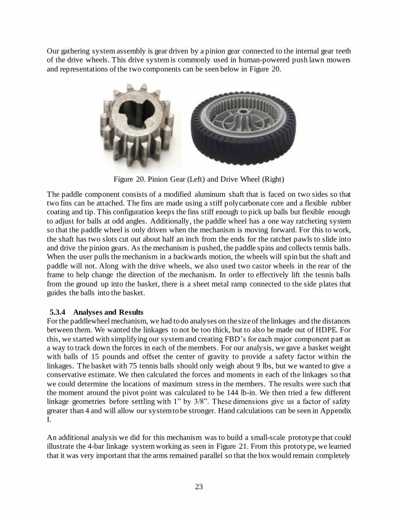
Our gathering system assembly is gear driven by a pinion gear connected to the internal gear teeth of the drive wheels. This drive system is commonly used in human-powered push lawn mowers
and representations of the two components can be seen below in Figure 20.
Figure 20. Pinion Gear (Left) and Drive Wheel (Right)
The paddle component consists of a modified aluminum shaft that is faced on two sides so that two fins can be attached. The fins are made using a stiff polycarbonate core and a flexible rubber coating and tip. This configuration keeps the fins stiff enough to pick up balls but flexible enough
to adjust for balls at odd angles. Additionally, the paddle wheel has a one way ratcheting system so that the paddle wheel is only driven when the mechanism is moving forward. For this to work,
the shaft has two slots cut out about half an inch from the ends for the ratchet pawls to slide into and drive the pinion gears. As the mechanism is pushed, the paddle spins and collects tennis balls. When the user pulls the mechanism in a backwards motion, the wheels will spin but the shaft and
paddle will not. Along with the drive wheels, we also used two castor wheels in the rear of the frame to help change the direction of the mechanism. In order to effectively lift the tennis balls
from the ground up into the basket, there is a sheet metal ramp connected to the side plates that guides the balls into the basket.
5.3.4 Analyses and Results
For the paddlewheel mechanism, we had to do analyses on the size of the linkages and the distances between them. We wanted the linkages to not be too thick, but to also be made out of HDPE. For
this, we started with simplifying our system and creating FBD’s for each major component part as a way to track down the forces in each of the members. For our analysis, we gave a basket weight with balls of 15 pounds and offset the center of gravity to provide a safety factor within the
linkages. The basket with 75 tennis balls should only weigh about 9 lbs, but we wanted to give a conservative estimate. We then calculated the forces and moments in each of the linkages so that
we could determine the locations of maximum stress in the members. The results were such that the moment around the pivot point was calculated to be 144 lb-in. We then tried a few different linkage geometries before settling with 1” by 3/8”. These dimensions give us a factor of safety
greater than 4 and will allow our system to be stronger. Hand calculations can be seen in Appendix I.
An additional analysis we did for this mechanism was to build a small-scale prototype that could illustrate the 4-bar linkage system working as seen in Figure 21. From this prototype, we learned
that it was very important that the arms remained parallel so that the box would remain completely
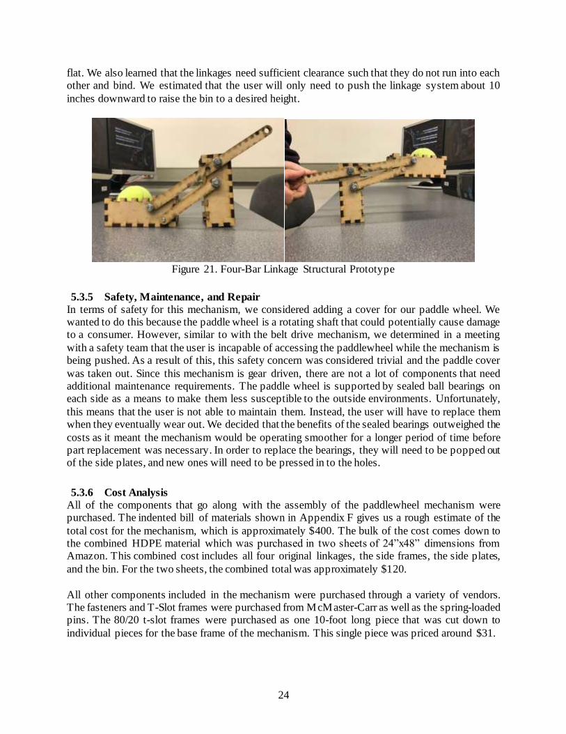
24
flat. We also learned that the linkages need sufficient clearance such that they do not run into each other and bind. We estimated that the user will only need to push the linkage system about 10
inches downward to raise the bin to a desired height.
Figure 21. Four-Bar Linkage Structural Prototype
5.3.5 Safety, Maintenance, and Repair
In terms of safety for this mechanism, we considered adding a cover for our paddle wheel. We wanted to do this because the paddle wheel is a rotating shaft that could potentially cause damage to a consumer. However, similar to with the belt drive mechanism, we determined in a meeting
with a safety team that the user is incapable of accessing the paddlewheel while the mechanism is being pushed. As a result of this, this safety concern was considered trivial and the paddle cover
was taken out. Since this mechanism is gear driven, there are not a lot of components that need additional maintenance requirements. The paddle wheel is supported by sealed ball bearings on each side as a means to make them less susceptible to the outside environments. Unfortunately,
this means that the user is not able to maintain them. Instead, the user will have to replace them when they eventually wear out. We decided that the benefits of the sealed bearings outweighed the
costs as it meant the mechanism would be operating smoother for a longer period of time before part replacement was necessary. In order to replace the bearings, they will need to be popped out of the side plates, and new ones will need to be pressed in to the holes.
5.3.6 Cost Analysis
All of the components that go along with the assembly of the paddlewheel mechanism were purchased. The indented bill of materials shown in Appendix F gives us a rough estimate of the
total cost for the mechanism, which is approximately $400. The bulk of the cost comes down to the combined HDPE material which was purchased in two sheets of 24”x48” dimensions from Amazon. This combined cost includes all four original linkages, the side frames, the side plates,
and the bin. For the two sheets, the combined total was approximately $120.
All other components included in the mechanism were purchased through a variety of vendors. The fasteners and T-Slot frames were purchased from McMaster-Carr as well as the spring-loaded pins. The 80/20 t-slot frames were purchased as one 10-foot long piece that was cut down to
individual pieces for the base frame of the mechanism. This single piece was priced around $31.
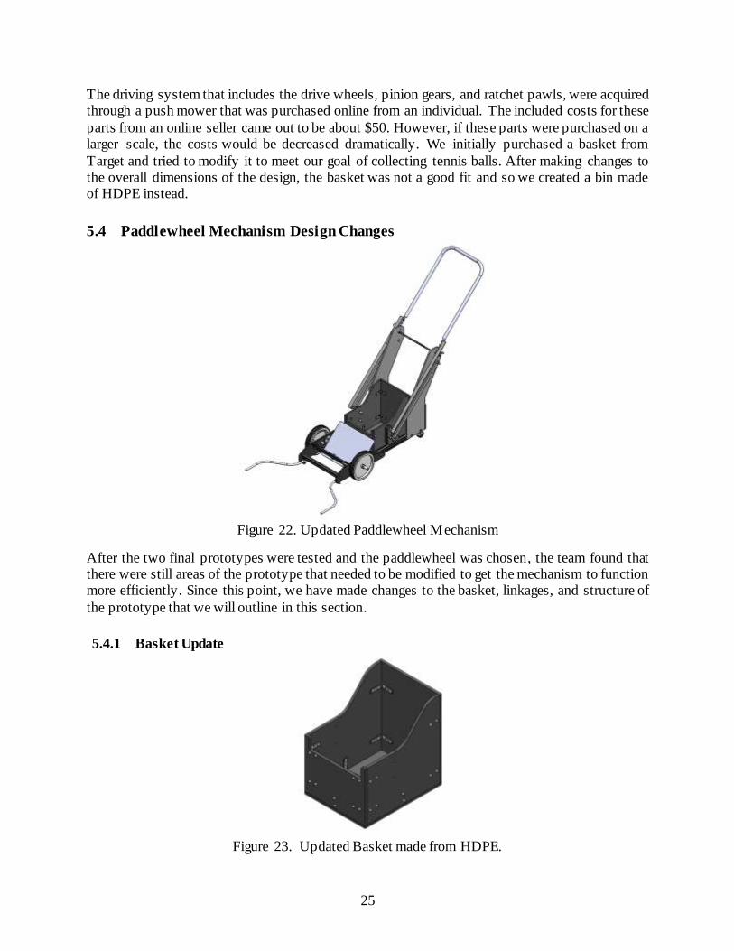
25
The driving system that includes the drive wheels, pinion gears, and ratchet pawls, were acquired through a push mower that was purchased online from an individual. The included costs for these
parts from an online seller came out to be about $50. However, if these parts were purchased on a larger scale, the costs would be decreased dramatically. We initially purchased a basket from
Target and tried to modify it to meet our goal of collecting tennis balls. After making changes to the overall dimensions of the design, the basket was not a good fit and so we created a bin made of HDPE instead.
5.4 Paddlewheel Mechanism Design Changes
Figure 22. Updated Paddlewheel Mechanism
After the two final prototypes were tested and the paddlewheel was chosen, the team found that there were still areas of the prototype that needed to be modified to get the mechanism to function more efficiently. Since this point, we have made changes to the basket, linkages, and structure of
the prototype that we will outline in this section.
5.4.1 Basket Update
Figure 23. Updated Basket made from HDPE.
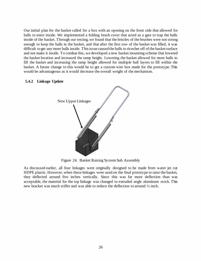
26
Our initial plan for the basket called for a box with an opening on the front side that allowed for
balls to enter inside. We implemented a folding brush cover that acted as a gate to trap the balls inside of the basket. Through our testing, we found that the bristles of the brushes were not strong
enough to keep the balls in the basket, and that after the first row of the basket was filled, it was difficult to get any more balls inside. This issue caused the balls to ricochet off of the basket surface and not make it inside. To combat this, we developed a new basket mounting scheme that lowered
the basket location and increased the ramp height. Lowering the basket allowed for more balls to fill the basket and increasing the ramp height allowed for multiple ball layers to fill within the
basket. A future change to this would be to get a custom wire box made for the prototype. This would be advantageous as it would decrease the overall weight of the mechanism.
5.4.2 Linkage Update
Figure 24. Basket Raising System Sub Assembly
As discussed earlier, all four linkages were originally designed to be made from water jet cut HDPE plastic. However, when these linkages were used on the final prototype to raise the basket, they deflected around five inches vertically. Since this was far more deflection than was
acceptable, the material for the top linkage was changed to extruded angle aluminum stock. This new bracket was much stiffer and was able to reduce the deflection to around ½-inch.
New Upper Linkages
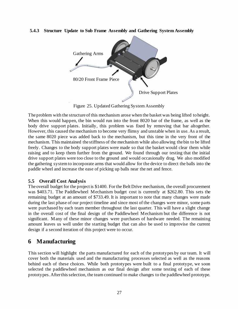
27
5.4.3 Structure Update to Sub Frame Assembly and Gathering System Assembly
Figure 25. Updated Gathering System Assembly
The problem with the structure of this mechanism arose when the basket was being lifted to height.
When this would happen, the bin would run into the front 8020 bar of the frame, as well as the body drive support plates. Initially, this problem was fixed by removing that bar altogether. However, this caused the mechanism to become very flimsy and unstable when in use. As a result,
the same 8020 piece was added back to the mechanism, but this time in the very front of the mechanism. This maintained the stiffness of the mechanism while also allowing the bin to be lifted
freely. Changes to the body support plates were made so that the basket would clear them while raising and to keep them further from the ground. We found through our testing that the initial drive support plates were too close to the ground and would occasionally drag. We also modified
the gathering system to incorporate arms that would allow for the device to direct the balls into the paddle wheel and increase the ease of picking up balls near the net and fence.
5.5 Overall Cost Analysis The overall budget for the project is $1400. For the Belt Drive mechanism, the overall procurement was $403.71. The Paddlewheel Mechanism budget cost is currently at $262.80. This sets the remaining budget at an amount of $733.49. It is important to note that many changes were made
during the last phase of our project timeline and since most of the changes were minor, some parts were purchased by each team member throughout the last quarter. This will have a slight change
in the overall cost of the final design of the Paddlewheel Mechanism but the difference is not significant. Many of these minor changes were purchases of hardware needed. The remaining amount leaves us well under the starting budget that can also be used to improvise the current
design if a second iteration of this project were to occur.
6 Manufacturing
This section will highlight the parts manufactured for each of the prototypes by our team. It will cover both the materials used and the manufacturing processes selected as well as the reasons
behind each of these choices. While both prototypes were built to a final prototype, we soon selected the paddlewheel mechanism as our final design after some testing of each of these
prototypes. After this selection, the team continued to make changes to the paddlewheel prototype.
Drive Support Plates
80/20 Front Frame Piece
Gathering Arms

28
As a result, the manufacturing of the paddlewheel mechanism is slightly more extensive. In addition, our future recommendations for manufacturing will only pertain to the paddlewheel
mechanism.
6.1 Belt Drive Mechanism As discussed before, the belt drive mechanism was constructed mostly from purchased parts. An
overview of the manufacturing plan for both the purchased and manufactured parts of the model will be described in the sections below.
6.1.1 Procurement
The following section will discuss where each of the purchased components for the Belt Drive Mechanism were purchased from. For a more in-depth look at all of the purchased parts of this
model, refer to the Purchased Part Detail List in Appendix G. This list contains website references to the data sheets of all of the purchased parts.
6.1.1.1 McMaster-Carr Parts
The large majority of the parts for this model were purchased from the online part supplier McMaster-Carr. A full list of the purchased parts and costs of parts from this manufacturer can be
seen below in Table 4.
Table 4. Purchased parts from McMaster-Carr with costs.
Part Name Cost
Conveyor Roller (x2) $25.48
Lift Belt $51.28
Alligator Lacing $46.38
Drive Belt 21.5” $4.35
Drive Belt 23” $9.57
Bearing Mounts (x2) $7.40
Key $0.68
Belt Pulley $20.75
Bolts (x4) $21.76
Hex Nuts (x4) $25.44
Lock Nuts (x4) $27.44
Screws (x12) $21.76
While parts from McMaster-Carr were slightly more expensive than other suppliers, the ease of purchasing almost all of the parts from one supplier was incredibly convenient.
6.1.1.2 HDPE Sheets
As stated before in Section 5.2.3, each of the 3/8-inch HDPE sheets were bought online from Amazon. Two sheets of two foot by four foot sheets were enough to construct the entire prototype,
and each of these sheets cost around $63.
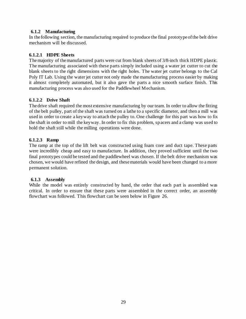
29
6.1.2 Manufacturing
In the following section, the manufacturing required to produce the final prototype of the belt drive
mechanism will be discussed.
6.1.2.1 HDPE Sheets
The majority of the manufactured parts were cut from blank sheets of 3/8-inch thick HDPE plastic. The manufacturing associated with these parts simply included using a water jet cutter to cut the blank sheets to the right dimensions with the right holes. The water jet cutter belongs to the Cal
Poly IT Lab. Using the water jet cutter not only made the manufacturing process easier by making it almost completely automated, but it also gave the parts a nice smooth surface finish. This
manufacturing process was also used for the Paddlewheel Mechanism.
6.1.2.2 Drive Shaft
The drive shaft required the most extensive manufacturing by our team. In order to allow the fitting of the belt pulley, part of the shaft was turned on a lathe to a specific diameter, and then a mill was used in order to create a keyway to attach the pulley to. One challenge for this part was how to fix
the shaft in order to mill the keyway. In order to fix this problem, spacers and a clamp was used to hold the shaft still while the milling operations were done.
6.1.2.3 Ramp The ramp at the top of the lift belt was constructed using foam core and duct tape. These parts were incredibly cheap and easy to manufacture. In addition, they proved sufficient until the two
final prototypes could be tested and the paddlewheel was chosen. If the belt drive mechanism was chosen, we would have refined the design, and these materials would have been changed to a more
permanent solution.
6.1.3 Assembly
While the model was entirely constructed by hand, the order that each part is assembled was
critical. In order to ensure that these parts were assembled in the correct order, an assembly flowchart was followed. This flowchart can be seen below in Figure 26.

30
Figure 26. Assembly flowchart for Belt Drive Model.
One of the most significant challenges with the assembly of this model was attaching the conveyor
rollers to the second side plate. This was difficult because the conveyor rollers had to be stretched enough to provide tension in the belt. This problem was solved by having two team members stretch the rollers apart until they would both fit into the holes in the side plates.
6.2 Paddle Mechanism As previously discussed, we manufactured all of the flat HDPE sheets and linkages of the paddle wheel mechanism. However, we still purchased as many parts as possible from outside vendors
and suppliers.
6.2.1 Procurement
For the paddle wheel mechanism, we purchased parts from McMaster-Carr, Amazon, and Home Depot. We would have needed to spend approximately $40 on our drive system (ordered from sears), and an additional $20 on our handle bar (from repairclinic.com), but we were able to find
them used locally for a lower cost for this prototype. However, as we continue on in the manufacturing process, we will need to order these parts for future builds. A majority of the
hardware required for this design can be purchased through McMaster-Carr and can be seen outlined in Table 5. From the table you can see that we will be spending $125 at McMaster-Carr.

31
Table 5. McMaster-Carr Parts.
Part Name Cost
Retractable Spring $21.54
Brush holder $7.51
Brushes(x2) $13.17
80/20 10ft $16.00
Aluminum Shaft 6ft. $21.13
Castor Wheels $8.80
T-slot fasteners $16.10
T-slot anchors $13.56
Total $117.81
6.2.2 Manufacturing
The manufacturing steps necessary to complete the final paddlewheel prototype were slightly more extensive than those necessary for the belt drive. This is because the paddlewheel mechanism was built in order to make the final selection between prototypes, and then continually modified to
increase the efficiency of the mechanism. All of the manufacturing steps required are described in the section below.
6.2.2.1 Flat sheet pieces
The parts of this design that are made out of 3/8-inch HDPE sheets are the body drive support plates, lower arm linkages, body basket support plates, the basket and basket mounts, and the rear
body plate. All of these parts were manufactured utilizing a water jet cutter. Figure 27 shows a picture of the water jet cutting process.
Figure 27. HDPE Water Jet Cutting
The HDPE sheets provide a variety of benefits over aluminum, steel, or wood. Some of these
include the facts that it is incredibly easy to manufacture with a water jet cutter, lightweight, and stiff enough to provide structural support. Additionally, the HDPE will withstand the elements

32
better as it will not corrode. The ease of manufacturing of these sheets allowed us to make updates and changes to our prototype by easily modifying our CAD files.
6.2.2.2 8020 Frame
The frame for the paddlewheel mechanism was designed and built from 8020 aluminum t-slot bars.
This material was chosen because it is both acceptably stiff and incredibly easy to manufacture and modify. Additionally, this material gave us flexibility with mounting as we were able to slide bolts along the slots. These bars were cut to length using a horizontal band saw then holes were
drilled in the cross rails using the mill. Once each piece was manufactured, they were assembled together to form the frame of the mechanism as part of the Sub frame assembly. These processes
can be seen below in Figure 28.
(a) Holes Drilled for Assembly. (b) Assembly of Frame.
Figure 28. Manufacture and Assembly of 8020 Frame.
6.2.2.3 Paddlewheel Drive Shaft
The paddle wheel drive shaft was our most time-consuming part to manufacture. In order to create the shaft, it first was cut to length using a horizontal band saw. Next, a manual lathe was used to
face the ends to a precise length and turn down the end diameters to allow bearings to be pressed in place. After this, a mill was used to create slots in the ends for the ratchet pawls and face the top
and bottom surfaces flat to allow for paddle attachment, as well as drill holes through the shaft in order to attach the paddles. Some images from this manufacturing can be seen below in Figure 29.

33
(a) Slots drilled for ratchet
pawls. (b) Flats milled for paddle
attachment.
Figure 29. Manufacture of paddlewheel drive shaft.
One of the main challenges of this part was the large amount of manufacturing time necessary to create the part. Since three different machines were used to create the part, it took our team
members around four hours to complete manufacturing of the shaft. While this was not detrimental to our project, it is important to recognize that this machine time might become a problem if and
when the product is brought into mass production. Additionally, we ran into trouble creating the slots for the ratchet pawls but we think that this could be corrected if we had the proper size end mill, or possibly a broach to create the pocket.
6.2.2.4 Linkages
While the original plan was to manufacture all four linkages out of HDPE plastic, it was soon
determined that the load from lifting the basket caused a significant deflection in the linkages. In order to alleviate this problem, the top linkages were manufactured from extruded angle aluminum. Since these top linkages became much stiffer than the bottom linkages, they were able to hold the
majority of the load from the basket. In addition, the increased stiffness was able to drastically reduce the deflection problem by limiting the maximum deflection to around 1/2-inch.
6.2.2.5 Tennis Ball Bin
Throughout the design process, our bin underwent a number of different iterations. Initially, the bin was manufactured by modifying a store-bought plastic storage bin by cutting a slot in the
bottom. Brushes were then attached to the slot to allow balls to enter the bin, but to prevent them from exiting. This bin had a variety of problems. First of all, the brushes were unreliable and would
often keep balls from entering the bin and spit them back out. Also, once the bin filled with one layer of balls, those balls would also prevent other tennis balls from entering the bin. This problem was fixed by redesigning the bin to have an open top and allowing balls to pop into the top of the
bin. The first bin manufactured for this purpose was made from spare wood parts to show the functionality of this concept. Once the concept was proven, the bin was remade from water jet cut
HDPE sheets. The bin was assembled using brackets and bolts to connect each of the HDPE panels. The final bin can be seen in Figure 30.

34
Figure 30. Final HDPE bin.
This provided a bin that was not only sturdy, but also matched the aesthetics of the rest of the
mechanism.
6.2.2.6 Ball Ramp
The ball ramp that transfers tennis balls from the paddle into the basket was made from 0.020-inch steel sheet metal. This sheet metal was cut into the correct dimensions and then two flanges were added to the sides in order to connect the ramp to the HDPE panels on the sides. However, a
problem arose when initially testing out this sheet metal ramp: the metal was far too thin and would deflect significantly when tennis balls were pushed into it. Our team attempted to solve this problem by folding over the ends of the ramp into 180-degree tabs to add stiffness, but the problem
was still there. As a result, a piece of plywood was attached to the back of the ramp using duct tape. Figure 27 below shows the temporary solution for the ball ramp in both a functional position
and a folded-over position for storage.
(a) Ramp in functional position. (b) Ramp in folded position
for storage.
Figure 31. Temporary ball ramp in various positions.

35
Although this solved the problem, it is not aesthetically pleasing and obviously not a viable solution for a mass-produced product. In order to fix this problem more effectively, a sheet metal
with a larger thickness such as 1/8-inch sheet metal, should be used. This will remove the deflection problem while also improving the beauty of the mechanism.
6.2.2.7 Connecting Hardware
As the prototype was assembled, many different types of connectors were used in order to hold the mechanism together. For the majority of functions, including attaching the linkages , spring-
loaded pins, and the handle to the frame, bolts with nylon locknuts were used. Additionally, brackets were used to connect the HDPE bin as well as some of the HDPE frame pieces. These
brackets were used because drilling holes and inserting screws into the plastic often resulted in a bulge in the plastic and a less-than-optimal hold. Finally, the 80/20 frame was assembled using 80/20 anchors, and the body plates were attached using bolts and t-nuts.
6.2.3 Assembly
For the Paddlewheel mechanism, the entire system was assembled in the three sub-assemblies
mentioned in Section 5.1 (sub frame assembly, basket raising system, and gathering system assembly). The main chassis and the drive paddle assembly needed to be assembled in a specific
way as to be sure that all parts would be able to be attached correctly. For sub frame assembly, the flowchart of Figure 32 was followed to ensure that it is assembled correctly . For the gathering system assembly, the flowchart of Figure 33 needed to be followed. Once these two subassemblies
were assembled, the basket and linkages assembly could be added on top.
Figure 32. Flowchart for sub frame assembly.
Figure 33. Flowchart for gathering system assembly.

36
7 Design Verification
For each model, the structural prototype was used to conduct testing for at least one function of
the model; however, the next prototypes will be fully functional and will be used to conduct further testing on the models. In order to document our tests and results, a Design Verification Plan and Results (DVP&R) table was constructed. Using the DVP&R table, our team was able to plan when
each of these tests will be conducted, as well as who will be in charge of each test. The entire DVP&R table can be found in Appendix K, but description of some of the individual tests can be
found below.
7.1 Paddlewheel Mechanism Tests There were five critical tests that we wanted to accomplish to ensure a functioning and reliable working prototype. These tests are listed and described below.
7.1.1 Ease-of-Use Test
The ease-of-use test was performed to collect data on how much force a user would need to push
the Paddlewheel mechanism. The equipment used for this test was a push/pull gauge, in particular, an Omega DFG35-100 shown in Figure 34 below. The test was performed with four different amounts of tennis balls in the bin. There were four trials that ran for the different amounts of tennis
balls and the force was collected for each trial. It is important to note that while we ran this test, there were a few times that tennis balls jammed up against the ramp. T his jamming of tennis balls
caused the force gauge to increase, but the change was not significant enough to skew our data. Also, we noted that more jams were caused when the mechanism was pulled at a lower speed than when pulled at an average walking speed of approximately 3ft/s.
(a) Force Gauge DFG35-100. (b) Position and angle used for pulling the mechanism.
Figure 34. The force gauge was used in a pulling motion due to the difficulty of pushing the mechanism.

37
The test was setup with 20 tennis balls lined up in a 10-foot span and randomized as single or double tennis balls. Figure 35 shows a section of the actual setup and how the device was utilized
to perform the test.
(a) Test setup before the test begins. (b) The paddlewheel mechanism in motion as
it collects tennis balls.
Figure 35. The Ease-of-Use test being performed by team member George.
The table below shows the data that was collected. The number of tennis balls jammed are noted in parentheses next to the force that was recorded.
Table 6. The forces recorded during the ease-of-use test including the number of balls jammed or overshot in parentheses during each trial.
# of Tennis Balls Trial 1 [lbf] Trial 2 [lbf] Trial 3 [lbf] Trial 4 [lbf]
0 11.2 (0) 11.0 (1) 13.2 (0) 15.2 (1)
20 12.4 (0) 12.1 (1) 10.3 (1) 10.4 (1)
40 14.4 (2) 18.6 (2) 17.8 (1) 17.4 (2)
60 14.4 (0) 14.1 (1) 11.3 (0) 14.0 (0)
Additionally, since this test was the one that contained the most numerical observations, a short statistical analysis was performed on the results. This involved finding the average and standard
deviation of the set of data. The average was determined to be 13.4 lbs. and the sample standard deviations was 2.7 lbs.
7.1.2 Transportability Test
The transportability test was important to perform because it was able to show us how quickly the prototype could be collapsed to its storage form. Currently, the hardware used are standard nuts

38
and bolts. This was taken into account as we needed to record the time it took to perform each step in collapsing the mechanism. The first step was to disengage the locking pins so that the user can
rotate the bin up to a horizontal position. Next, the user is to remove the bolts that hold the handle up so that the handle is able to come down and rest against the two upright plates of the mechanism.
During this step, the ramp is also moved and rotated over the paddles. The third step is to loosen the bolts that connect the two front side plates so that the subassembly with the two large wheels can slide towards the handles. Figure 36 shows the steps described above.
Step 1 Step 2
Step 3
Step 4
Figure 36. Steps required for collapsing mechanism.
Once all steps were completed, the final collapsed mechanism was measured to be 12.4 cubic ft. in volume and is shown below. The overall time it took to collapse the mechanism was 238 seconds, or 3 minutes 58 seconds.

39
Figure 37. Collapsed paddlewheel mechanism with a volume of 12.4 cubic ft.
For a more detailed manual on how to collapse the mechanism, refer to the Operators Manual in Appendix L.
7.1.3 Linkage Deflection Test
The linkage deflection test proved to be a critical test because our original linkages were not able to withstand the loads being applied. The initial linkages were made of HDPE and as mentioned
above in the manufacturing section, the modification was to replace those two top linkages to aluminum linkages that were more rigid and able to withstand higher loads. The deflection test
was performed by having the bin in a horizontal position, parallel to the ground. Having the bin at this position will create the maximum deflection at the end of the linkages where the bin is located because the load is not applied axially on the linkages. The deflection was measured from the
ground up to the top of the bin as shown in Figure 38 below.
Figure 38. Team member Tyler measuring the deflection with 20 tennis balls in the bin.
The test was performed five times with the following amounts of tennis balls: 10, 20, 30, 40, and 50. The table below shows the data collected while performing the linkage deflection test. It is

40
important to note that while the bin shown is made of wood, the modified bin made of HDPE weighed approximately the same. The initial height with no tennis balls was measured at 20 ¼
inches. Table 7. Linkage deflection data collected
Tennis
Balls Deflection [in]
10 20-1/8
20 20-1/16
30 19-15/16
40 19-3/4
50 19-5/8
The maximum vertical deflection of the bin noted was measured to be ½-inch.
7.1.4 Gathering Efficiency Test
The gathering efficiency test was one of our final tests performed once our working prototype was
complete. This efficiency of gathering the tennis balls depended on the amount of errors that were observed. Errors in this test were defined as tennis balls jamming up against the ramp more than
once and tennis balls that overshot or missed the bin. The following equations was used to determine the efficiency of our mechanism.
𝜂𝐺 =#𝑇𝐵 −#𝐸𝑟𝑟𝑜𝑟𝑠
#𝑇𝐵
where #TB is the total number of tennis balls used, #Errors is the number of tennis balls not picked
up, and 𝜂𝐺 is the gathering efficiency. For this test, team members Alex and George each performed two trials. Figure 39 shows the setup of the gathering efficiency test and the collecting of tennis balls.
Figure 39. Team member George performing the gathering efficiency test .
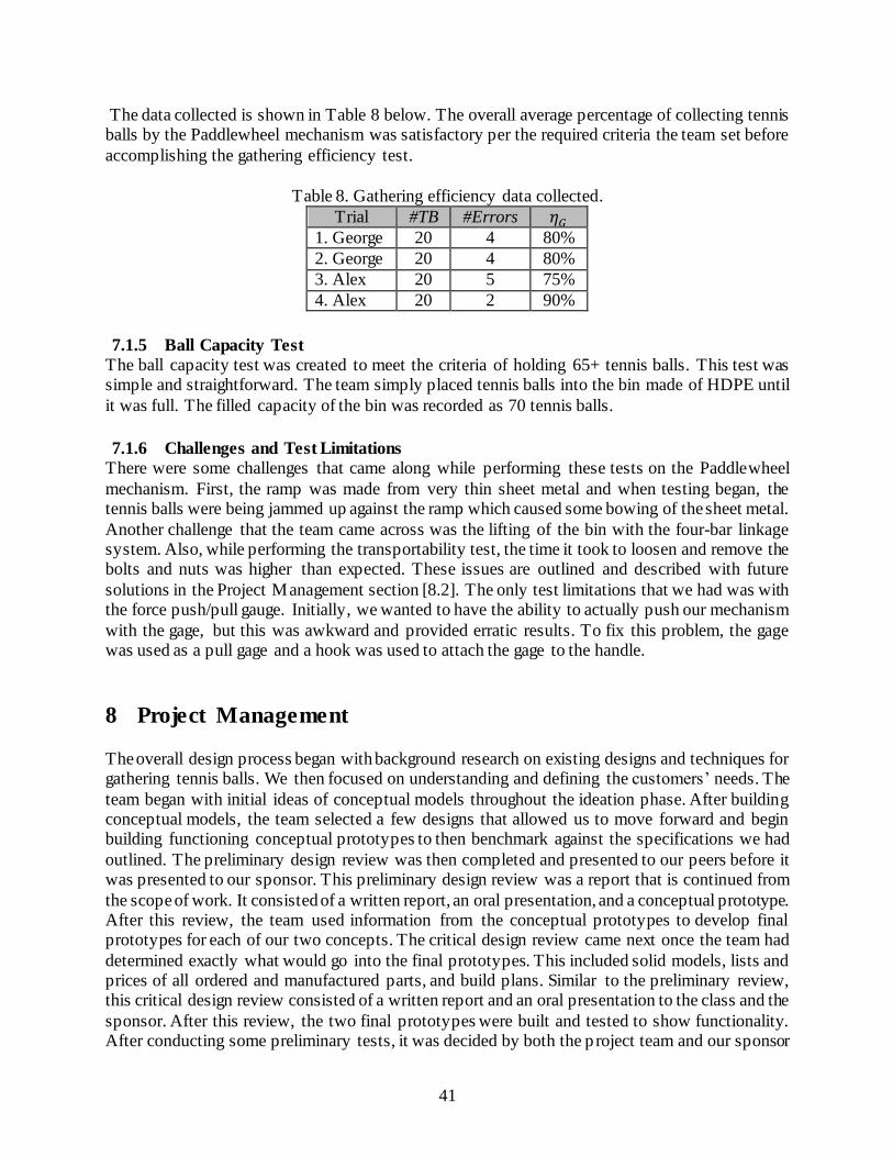
41
The data collected is shown in Table 8 below. The overall average percentage of collecting tennis balls by the Paddlewheel mechanism was satisfactory per the required criteria the team set before
accomplishing the gathering efficiency test.
Table 8. Gathering efficiency data collected.
Trial #TB #Errors 𝜂𝐺
1. George 20 4 80%
2. George 20 4 80%
3. Alex 20 5 75%
4. Alex 20 2 90%
7.1.5 Ball Capacity Test
The ball capacity test was created to meet the criteria of holding 65+ tennis balls. This test was simple and straightforward. The team simply placed tennis balls into the bin made of HDPE until
it was full. The filled capacity of the bin was recorded as 70 tennis balls.
7.1.6 Challenges and Test Limitations
There were some challenges that came along while performing these tests on the Paddlewheel
mechanism. First, the ramp was made from very thin sheet metal and when testing began, the tennis balls were being jammed up against the ramp which caused some bowing of the sheet metal.
Another challenge that the team came across was the lifting of the bin with the four-bar linkage system. Also, while performing the transportability test, the time it took to loosen and remove the bolts and nuts was higher than expected. These issues are outlined and described with future
solutions in the Project Management section [8.2]. The only test limitations that we had was with the force push/pull gauge. Initially, we wanted to have the ability to actually push our mechanism
with the gage, but this was awkward and provided erratic results. To fix this problem, the gage was used as a pull gage and a hook was used to attach the gage to the handle.
8 Project Management
The overall design process began with background research on existing designs and techniques for gathering tennis balls. We then focused on understanding and defining the customers’ needs. The
team began with initial ideas of conceptual models throughout the ideation phase. After building conceptual models, the team selected a few designs that allowed us to move forward and begin building functioning conceptual prototypes to then benchmark against the specifications we had
outlined. The preliminary design review was then completed and presented to our peers before it was presented to our sponsor. This preliminary design review was a report that is continued from
the scope of work. It consisted of a written report, an oral presentation, and a conceptual prototype. After this review, the team used information from the conceptual prototypes to develop final prototypes for each of our two concepts. The critical design review came next once the team had
determined exactly what would go into the final prototypes. This included solid models, lists and prices of all ordered and manufactured parts, and build plans. Similar to the preliminary review, this critical design review consisted of a written report and an oral presentation to the class and the
sponsor. After this review, the two final prototypes were built and tested to show functionality. After conducting some preliminary tests, it was decided by both the p roject team and our sponsor

42
that the paddlewheel mechanism would be our final design, and that concept was progressed. In preparation for the final design review, the final prototype was tested and continually modified as
challenges arose. Although many of the challenges were identified and fixed, some of these challenges required too much time to fix and were found too late in the design process and were
unable to be completed before the final design review. The problems that were unable to be solved can be found below in the Next Steps section. For the final design review, the senior project team presented the final prototype at Senior Project Expo with an accompanying poster that outlined the
design process. Additionally, this final design report was compiled in order to more comprehensively outline the design process throughout the project.
8.1 Gantt Chart In order to better organize the key deliverables shown above in Table 6, the team also created a Gantt chart using TeamGantt. With the use of this chart, the team knew approximately how long each deliverable would take to complete, any dependencies between deliverables, and who was in
charge of each deliverable. In order to stay on track, the team updated the Gantt chart weekly with deliverables for each week. The full Gantt chart can be seen in Appendix M.
8.2 Deviations from Original Plan While the project has gone largely according to plan, there have been various changes throughout the process that have required our team to make on-the-fly changes. Some of these changes are discussed in the section below.
8.2.1 Progression to Two Final Prototypes
Initially, our team believed that by the time of our preliminary design review, we would have
narrowed the number of our designs to one. However, after an early meeting with our sponsor Professor Chen, we discovered that he wanted us to progress our two final designs until both final prototypes were built and could be tested. This provided some unique challenges for our team.
Most importantly, it doubled the amount of work we needed to do by having us develop two ideas. In retrospect, this increased work led to some of the smaller design problems that arose later down
the road with our paddlewheel mechanism. If we were able to devote more time to the initial design process of that mechanism, the team might have been able to catch those design issues before building the final prototype.
8.2.2 HDPE Ordering Issue
Initially, the team planned to order all of our HDPE plastic from the supplier Interstate Plastics.
However, we soon realized that the shipping time from this company was around six weeks. Since that would severely disrupt our planned schedule, we decided to find a separate supplier. Fortunately, we were able to find HDPE sheets with the same thickness on Amazon for an even
cheaper price. Although these sheets were smaller, we simply ordered enough to account for all of our parts and had the sheets within a week.
9 Conclusion
The full project of a lightweight tennis ball pick-up and hopper proposed by Professor Chen at Cal
Poly, SLO is presented in this document with background research, objectives, and the process

43
that was taken to implement the design. The main goal was to deliver a product that was
lightweight, inexpensive, and durable. While two designs were progressed until the final prototype
stage, the paddlewheel mechanism was ultimately chosen as the final design because of its
reliability. After this decision was made, the team performed various tests on this final prototype
in order to gain concrete data on how well the mechanism performed. All of this data is represented
in and interpreted in this report. Additionally, the team continued to make changes to the
mechanism to increase its efficiency and aesthetic appeal. With the limited amount of time for the
project, not every desired design change was able to be implemented. As a result, some
recommendations for additional changes are outlined in the Next Steps section below. At its final
stage, our prototype is fully functional and ready to be used by any potential consumer. However,
in order to make the product more suitable for mass production, it is recommended that these Next
Steps be taken first.
9.1 Next Steps While our final prototype completely proves our paddlewheel concept and its viability as a final solution, the prototype still has a few problems that need to be addressed before it will be ready
for production. These problems and recommended changes for solving these problems are outlined below.
9.1.1 Connecting Hardware Problem
The mechanism is collapsible so that the user will be able to fit it in a car or storage space. However, the final prototype requires that the user use two wrenches in order to collapse both the
mechanism and the frame. Although this is possible, it is both incredibly time consuming and unrealistic to assume that the user will have two wrenches with them at all times when trying to store our product. In order to fix this problem, it is recommended that these nuts and bolts be
replaced with wing nuts and wing bolts. This way, the user will be able to collapse the mechanism faster and with only the use of their hands.
9.1.2 Collapsible Handle Problem
In order to reduce the amount of parts that needed to be manufactured, a handle was chosen from a previous lawn mower that also provided us with the wheels and pinion gear. Although this handle
serves its function of allowing the user to comfortably push the mechanism, it has a very obvious problem when the user tries to collapse the handle for storage. The base of the handle where it
connects to the frame is curved, and thus it is very awkward to try to tighten or loosen bolts onto this curved surface. Fixing this problem will be simple and will involve manufacturing our own handle that is flat at the base instead of curved.
9.1.3 Linkage Pin Problem
There are two problems with the spring-loaded pins that lock the linkages into place on the frame.
The first problem is that the pins are currently extending straight into the HDPE frame. Although this temporarily shows the functionality of the pins, it is slowly warping the area around the pinhole on the plastic from the load of the bin. In order to solve this problem, metal collars can be attached
to the plastic frame with holes for the pin at specific heights. This will hold the pin securely while transferring the load over a more distributed area and preventing plastic warpage. The second
problem is that currently, the pins must be pulled out at two spots. As a result of this, the process
44
of lifting the bin requires two people: one two push the handle and one to adjust both of the pins. This problem can be solved by flipping the spring-loaded pins around so that they are released
inward instead of outward. Then, a cable can be attached to the two pins and ran up to a lever attached to the top of the handle. This way, the user can pull the lever to release the pins and then
push the handle to lift the bin without the need for a second user.
9.1.4 Tipping Problem
Another problem arises when the user tries to lift the bin using the handle: the mechanism begins
to tip backwards. Currently, the problem is alleviated by having another user hold the front of the mechanism so that it does not tip. Obviously, this is not a viable solution as it is unreliable and
requires another user to lift the bin. In this instance, the mechanism is essentially a lever with the force being applied to the handle, the load at the bin, and the fulcrum at the rear castor wheels. The tipping problem can be solved by moving the fulcrum to increase stability in the system. This can
be accomplished by extending the 8020 frame back beyond the rear plastic sheet and attaching the castor wheels farther back on the frame.

45
References [1] “Abandonment of Patent Application.” Uspto.gov, The United States Patent and Trademark Office, www.uspto.gov/web/offices/pac/mpep/s711.html. [2] “Approval Tests.” Itftennis.com, International Tennis Federation, 2017,
www.itftennis.com/technical/balls/approval-tests.aspx. [3] “Golf Balls, Cricket Balls and Tennis Balls.” Princeton University, The Trustees of Princeton
University, www.princeton.edu/~asmits/Bicycle_web/sportsballs.html. [4] “What to Do with 325 Million Tennis Balls Per Year.” Sustainable City Network, 16 Mar. 2016, www.sustainablecitynetwork.com/topic_channels/public_works/article_16805af2-eb8a-
11e5-bc48-af9208f621b2.html. [5] “Corrosion: Galvanic Corrosion.” The Stainless Steel Information Center,
www.ssina.com/corrosion/galvanic.html.

A-1
Appendix A
Survey: Tennis Ball Hopper Questionnaire Questions:
1. On a scale from 1 (not important) to 5 (extremely important), please rate each of these factors based on to their relations tennis ball hoppers.
Light Weight
Durability
Mobile (to and from the car)
Inexpensive
Easy to Use
Comfort
Adjustable 2. How many balls would you want a tennis ball hopper to carry?
3. What are some issues that you have with current tennis ball hoppers? 4. What are some features that you like about a tennis ball hopper that you have used or some features that you wish were present on a tennis ball hopper? Please describe the hopper used if
applicable.
Results: 1. Chart A.1. Average responses of 17 tennis players from Cal Poly Tennis Club.
2. Average quantity of balls required for the hopper: 75 3. Common Issues:
Easily Broken
Heavy
Flimsy
Hard to transport
Bulky
0.0 0.5 1.0 1.5 2.0 2.5 3.0 3.5 4.0 4.5 5.0
Light Weight
Durability
Mobile
Inexpensive
Easy to Use
Comfortable
Adjustable

A-2
4. Features you like/wish you had:
Lightweight
Greater Stability
Store Tennis Balls when not in use
Locking Handles
Convert from stand to hopper
Adjustable handle
Wheels
List of Customer Wants/Needs
Wants it to carry 36-48 tennis balls
Wants it to weigh 6-10 lbs
Wants it to be purely mechanical
Wants it to be easy enough for a 5-year old to operate
Wants it to be mobile (Bring to and from court)
Wants it to cost $100-200
Wants it to be durable
Different Tennis Ball Hopper Designs
Figure A.1. Wilson Tennis Ball Hopper - $30

A-3
Figure A.2. Har-Tru Ball Mower - $500
Figure A.3. Tennis Ball Roller Mower and Hopper - $180
Figure A.4. Kollectaball CS60 - $170
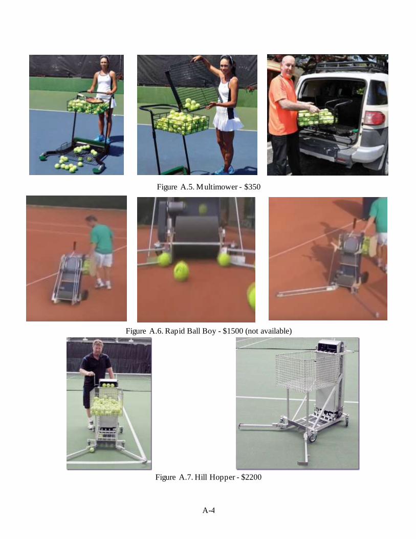
A-4
Figure A.5. Multimower - $350
Figure A.6. Rapid Ball Boy - $1500 (not available)
Figure A.7. Hill Hopper - $2200
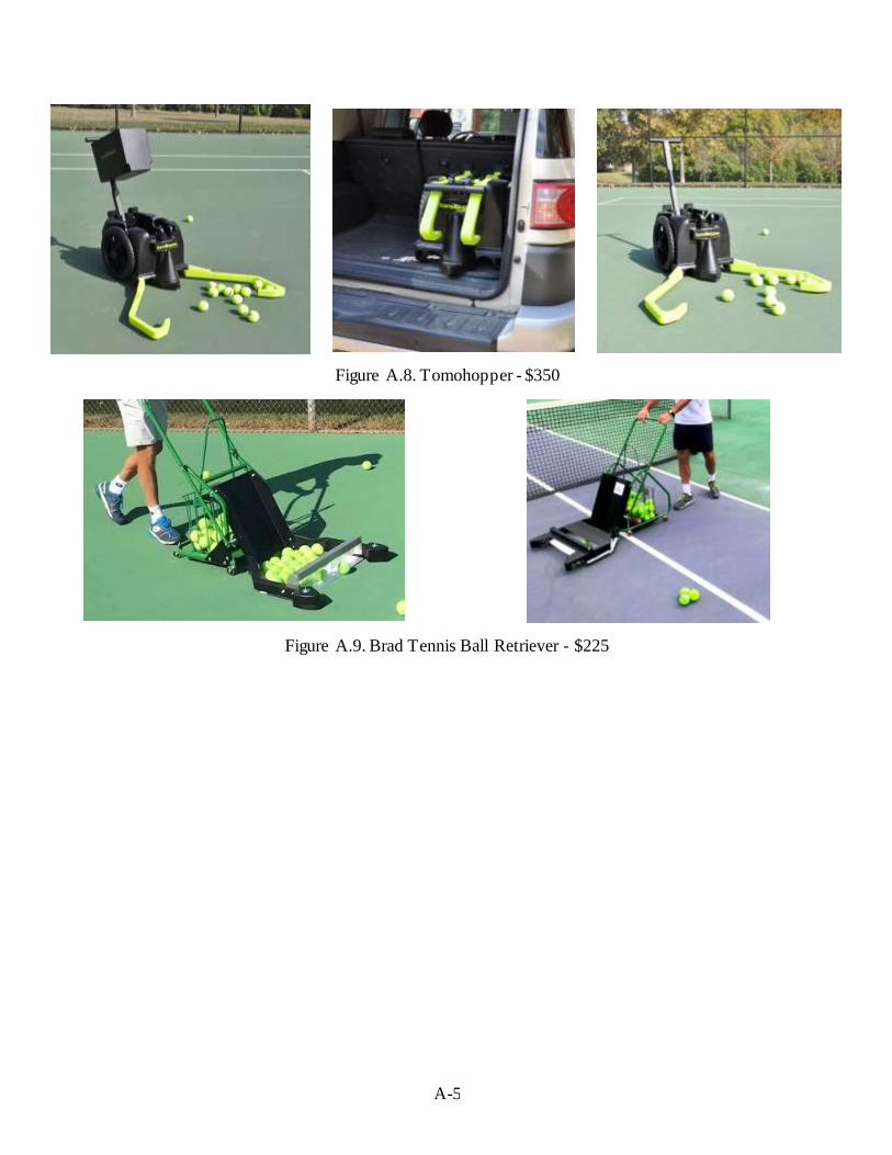
A-5
Figure A.8. Tomohopper - $350
Figure A.9. Brad Tennis Ball Retriever - $225

B-1
Appendix B
QFD: House of Quality
Figure B.1. Full QFD

B-2
Figure B.2. How vs. What Section
Figure B.3. Now vs. What Section

C-1
Appendix C
Ideation Session Notes and Decision Matrices Ideation Session #1 – Picking up Tennis Balls
Process - Brainwriting
Results o Pick up tennis balls with Velcro belt o Use concentric circles, rotating outer circle stationary inner circle
o Use stored energy from pushing to pick up balls o Suck up balls with vacuum power o Slide balls one at a time up tube
o Balls roll up a helical coil when picked up o Belt driven mechanism
o Slotted paddlewheel picks up balls o Use brushes to pick up balls o Lever brings up basket to usable height
o Swiveling vacuum head
Ideation Session #2 – Storing Tennis Balls
Process – Brainwriting
Results o Wire metal cage o Plastic/canvas bag o Plastic Tupperware-like container o Store in tube o Store in helix o Store on the ground o Store in the wheels o Collect and store in a net o Pressurized basket o Slotted box attached to mechanism o Container with spring loaded bottom, balls always at same height
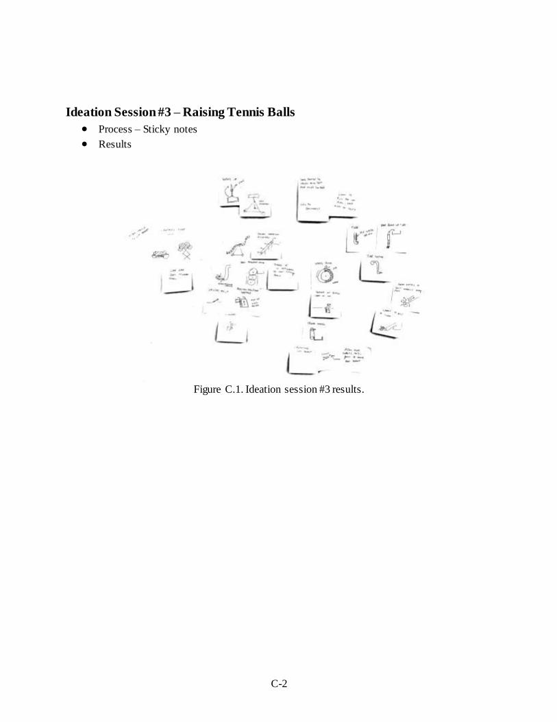
C-2
Ideation Session #3 – Raising Tennis Balls
Process – Sticky notes
Results
Figure C.1. Ideation session #3 results.

C-3
Ideation Session #4 – Transporting Tennis Balls
Process – Sticky notes
Results
Figure C.2. Ideation session #4 results.
Table C.1. Pugh Matrix focused on the function of gathering tennis balls
Concept
Paddlewheel Velcro Wheel Wide Arms Wheels Gather Balls Tomohopper
Criteria
Leightweight + + S + D
Durable + + S S
Mobile + + S + A
Inexpensive + + + +
Easy to Use - - S S T
Comfortable - - S -
Adjustable - - S S U
Sum(+) 4 4 1 3
Sum(-) 3 3 0 3 M
Sum(S) 0 0 6 1

C-4
Table C.2. Pugh Matrix showing the functions of transporting tennis balls to and from the court
Concept
Telescopic
Arms
Frame
as
Dolley
Basket
Lid
Detachable
Basket Collapsible
Backpack
carry
Retractable
handle Tomohopper
Criteria
Lightweight + + + S S + S D
Durable + - + S S + S
Mobile + + - S + + S A
Inexpensive - - - S S - S
Easy to Use - + + + + + S T
Comfortable S + S S + - S
Adjustable + + - + + + + U
Sum(+) 4 5 3 2 4 5 1
Sum(-) 2 2 3 0 0 2 0 M
Sum(S) 1 0 1 5 3 0 6
Table C.3. Pugh Matrix showing the function of raising tennis balls
Concept
Belt System Raising Basket Scissor Basket Spring Loading Wheel Launch Wheel Raise Tomohopper
Criteria
Adjustable S + S S + + D
Comfortable + + S + + -
Easy to Use + + S - + S A
Inexpensive - + - - + +
Mobile + - + - + + T
Durable - + + + + +
Lightweight + + + - S S U
Sum(+) 4 6 3 2 6 4
Sum(-) 2 1 1 4 0 1 M
Sum(S) 1 0 4 1 1 2
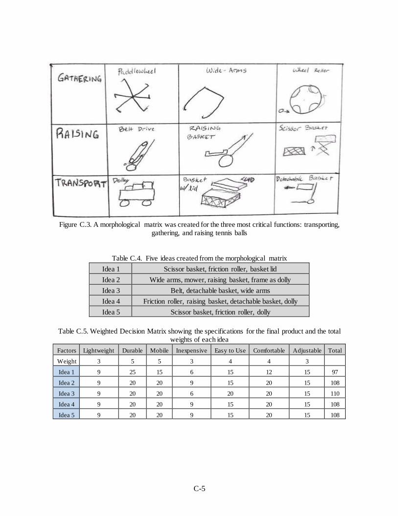
C-5
Figure C.3. A morphological matrix was created for the three most critical functions: transporting,
gathering, and raising tennis balls
Table C.4. Five ideas created from the morphological matrix
Idea 1 Scissor basket, friction roller, basket lid
Idea 2 Wide arms, mower, raising basket, frame as dolly
Idea 3 Belt, detachable basket, wide arms
Idea 4 Friction roller, raising basket, detachable basket, dolly
Idea 5 Scissor basket, friction roller, dolly
Table C.5. Weighted Decision Matrix showing the specifications for the final product and the total
weights of each idea
Factors Lightweight Durable Mobile Inexpensive Easy to Use Comfortable Adjustable Total
Weight 3 5 5 3 4 4 3
Idea 1 9 25 15 6 15 12 15 97
Idea 2 9 20 20 9 15 20 15 108
Idea 3 9 20 20 6 20 20 15 110
Idea 4 9 20 20 9 15 20 15 108
Idea 5 9 20 20 9 15 20 15 108
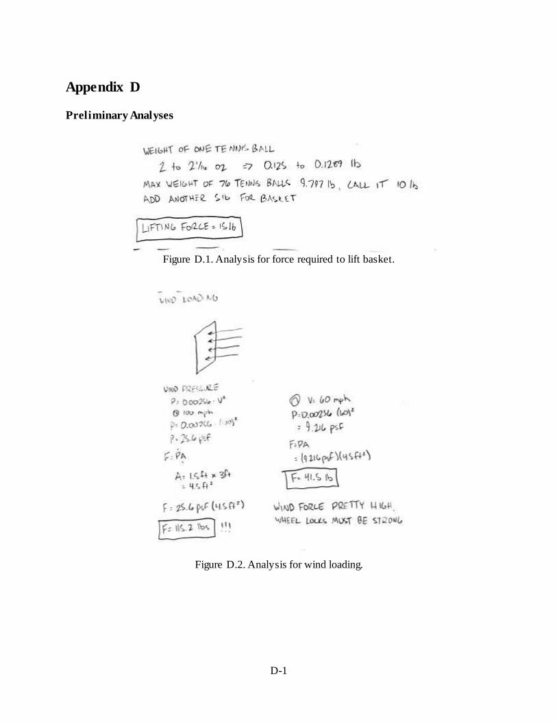
D-1
Appendix D
Preliminary Analyses
Figure D.1. Analysis for force required to lift basket.
Figure D.2. Analysis for wind loading.

D-2
Figure D.3. Analysis for bin volume.

E-1
Appendix E
Concept Layout Drawings
Figure E.1. Design Choice 1: this design uses a paddlewheel to pick up the balls and then
deposits them into the collection box. The box is then able to raise along the slide rails for a higher final position.

E-2
Figure E.2. Design Choice 2: this design utilizes a large friction belt to bring the balls from the
ground to a stationary collection box.
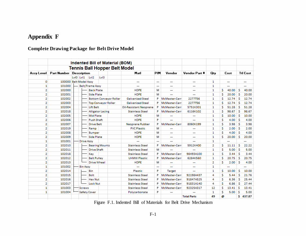
F-1
Appendix F
Complete Drawing Package for Belt Drive Model
Figure F.1. Indented Bill of Materials for Belt Drive Mechanism

F-2

F-3

F-4

F-5

F-6

F-7
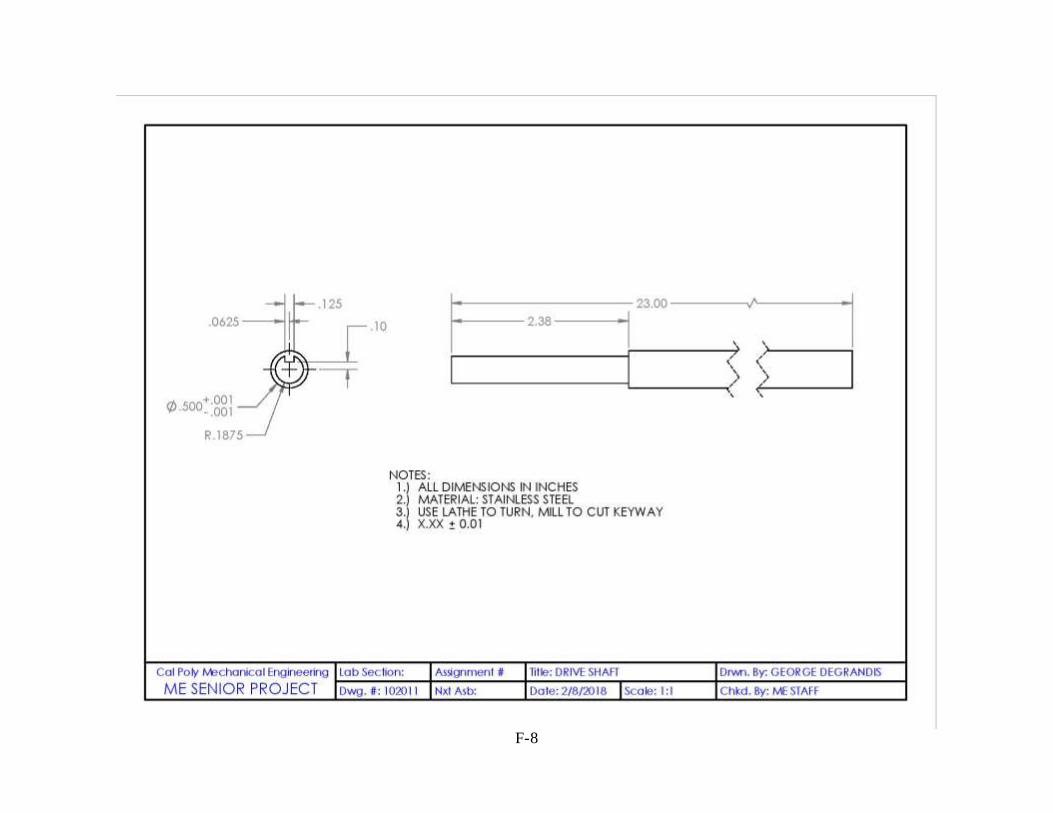
F-8

F-9

F-10
Complete Drawing Package for Paddlewheel Model

F-11
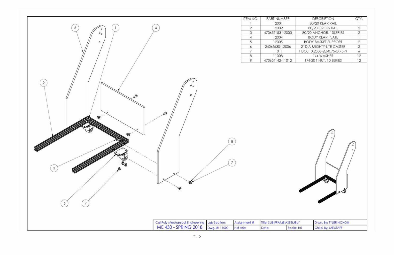
F-12

F-13

F-14

F-15

F-16

F-17

F-18

F-19
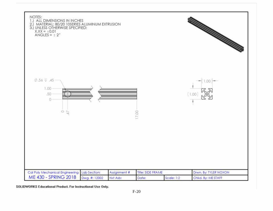
F-20

F-21

F-22

F-23

F-24

F-25

F-26

F-27
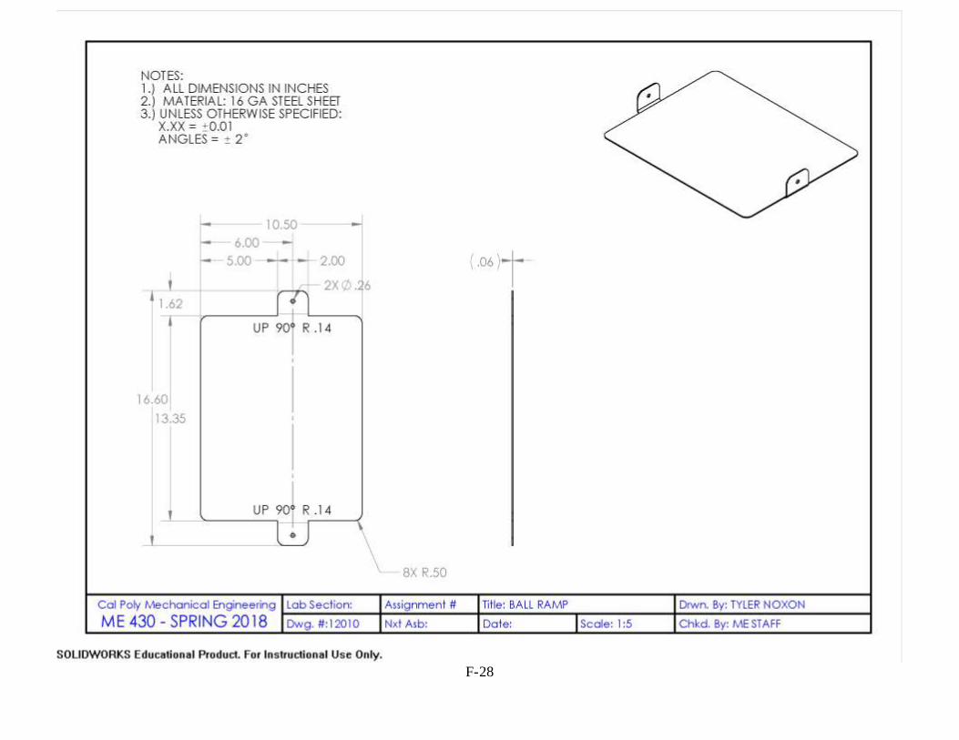
F-28

F-29

F-30

F-31

F-32

F-33

F-34

F-35

F-36
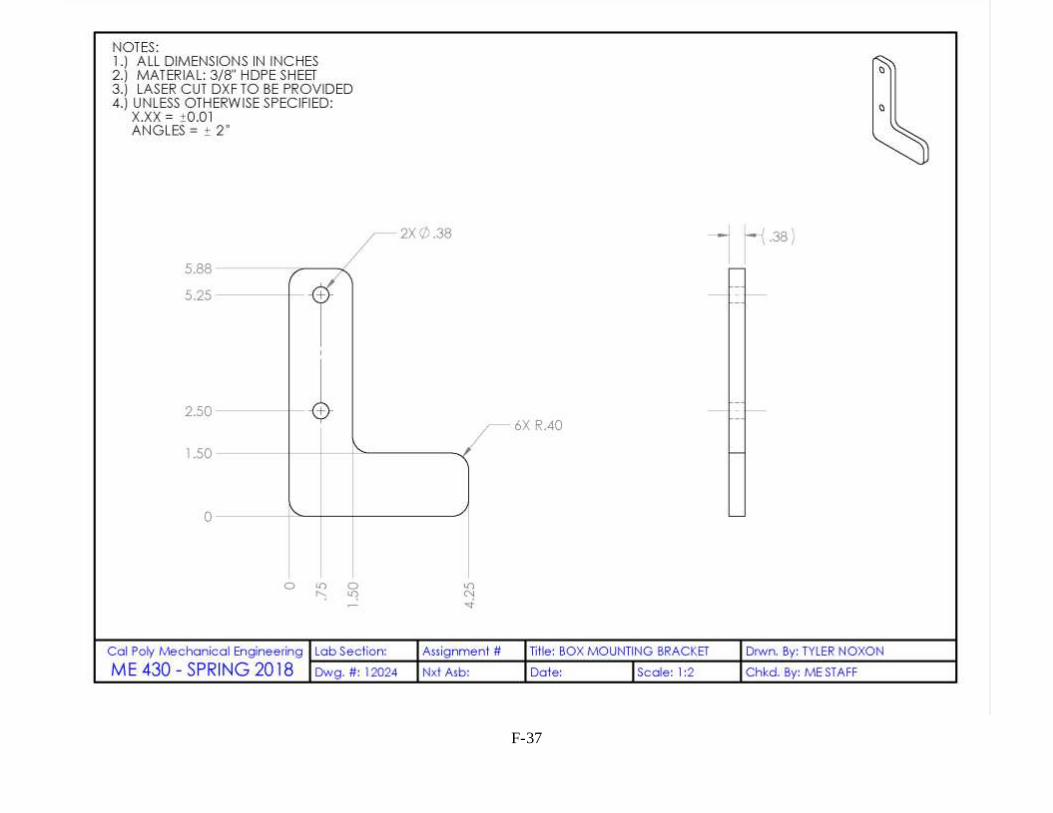
F-37

F-38

F-39
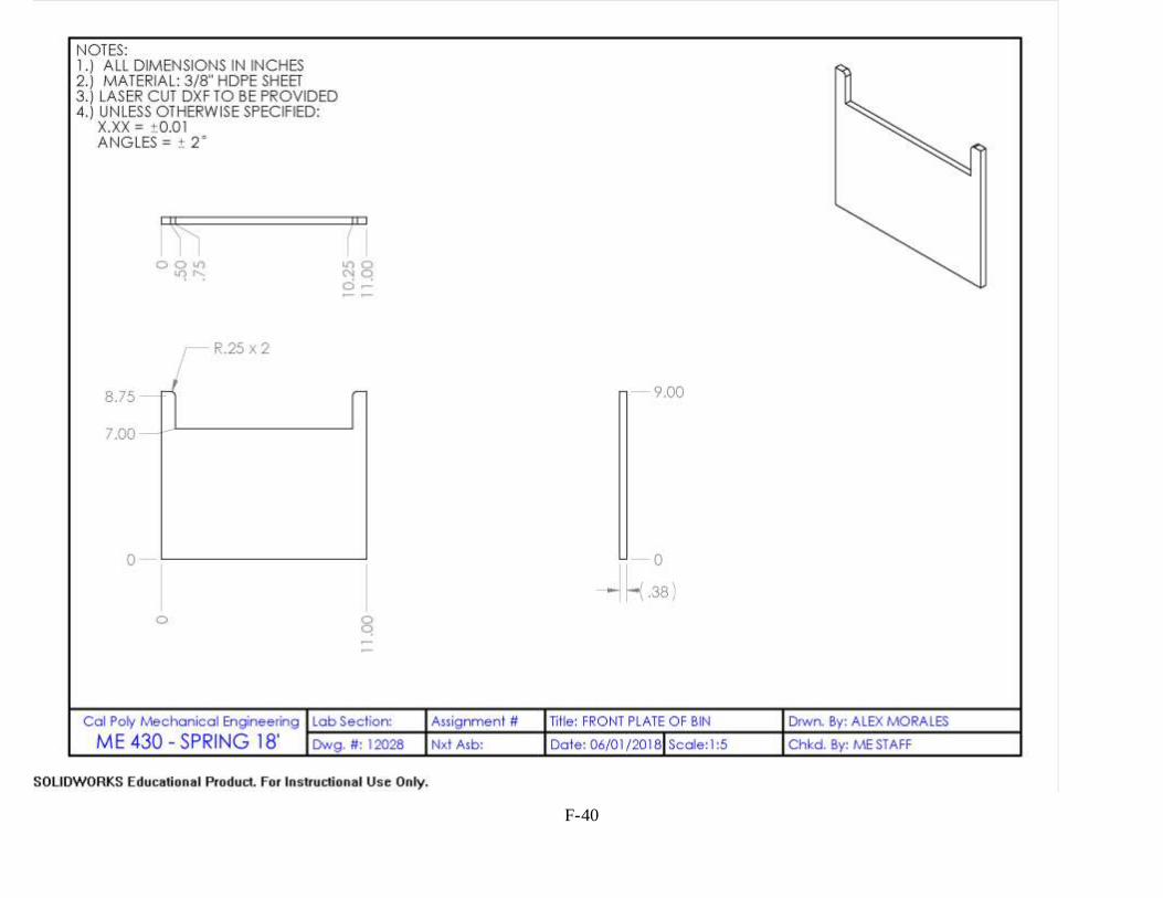
F-40

F-41

F-42

F-43

F-44

F-45

F-46

G-1
Appendix G
Purchased Parts Details
Table G.1. Link specifications of all parts needed for the Paddlewheel Mechanism
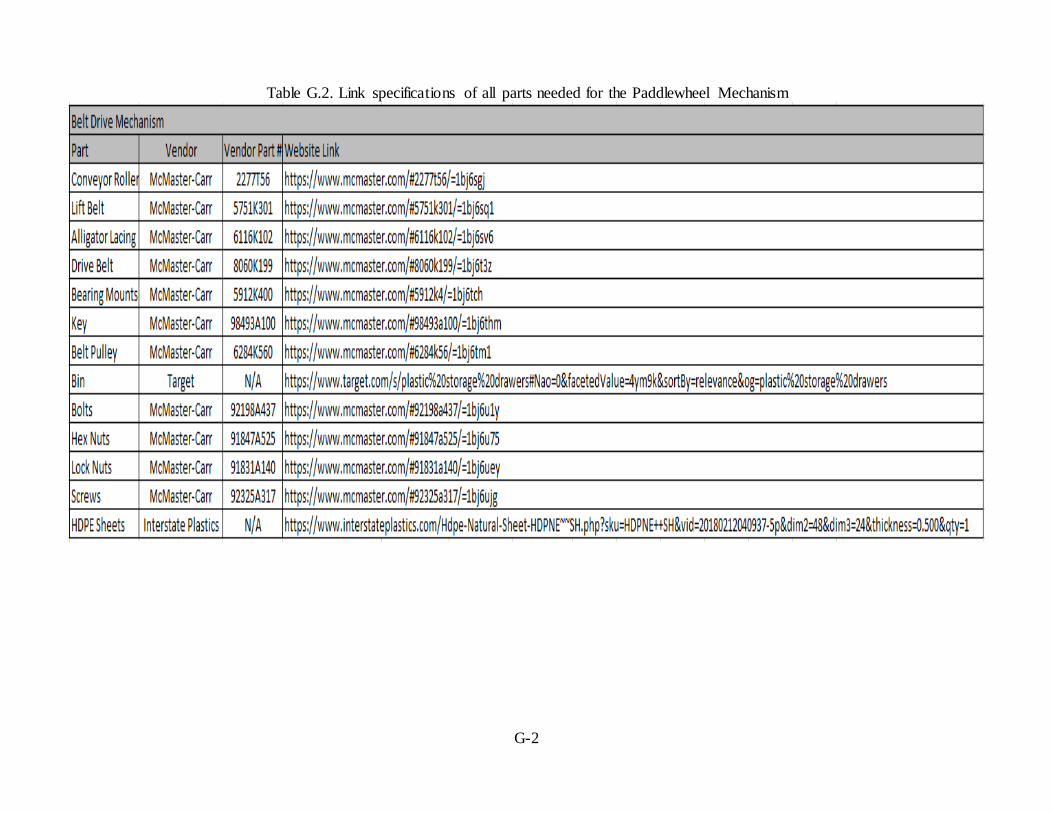
G-2
Table G.2. Link specifications of all parts needed for the Paddlewheel Mechanism
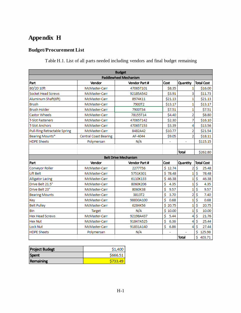
H-1
Appendix H
Budget/Procurement List
Table H.1. List of all parts needed including vendors and final budget remaining

I-1
Appendix I
Final Analyses Calculations

I-2

I-3

I-4

I-5

I-6

I-7
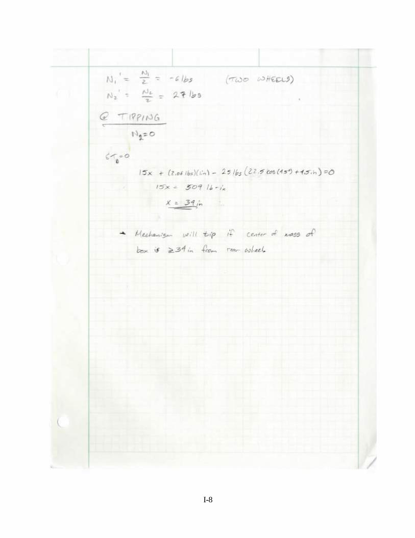
I-8

J-1
Appendix J
Safety Hazard Checklist/FMEA Team: ____Pursuit of Hoppiness________ Advisor: __Peter Schuster___ Date: _11/9/17___
Y N 1. Will the system include hazardous revolving, running, rolling, or mixing actions?
2. Will the system include hazardous reciprocating, shearing, punching, pressing,
squeezing, drawing, or cutting actions?
3. Will any part of the design undergo high accelerations/decelerations?
4. Will the system have any large (>5 kg) moving masses or large (>250 N) forces?
5. Could the system produce a projectile?
6. Could the system fall (due to gravity), creating injury?
7. Will a user be exposed to overhanging weights as part of the design?
8. Will the system have any burrs, sharp edges, shear points, or pinch points?
9. Will any part of the electrical systems not be grounded?
10. Will there be any large batteries (over 30 V)?
11. Will there be any exposed electrical connections in the system (over 40 V)?
12. Will there be any stored energy in the system such as flywheels, hanging weights or pressurized fluids/gases?
13. Will there be any explosive or flammable liquids, gases, or small particle fuel as part of the system?
14. Will the user be required to exert any abnormal effort or experience any abnormal
physical posture during the use of the design?
15. Will there be any materials known to be hazardous to humans involved in either
the design or its manufacturing?
16. Could the system generate high levels (>90 dBA) of noise?
17. Will the device/system be exposed to extreme environmental conditions such as
fog, humidity, or cold/high temperatures, during normal use?
18. Is it possible for the system to be used in an unsafe manner?
19. For powered systems, is there an emergency stop button?
20. Will there be any other potential hazards not listed above? If yes, please explain on reverse.
For any “Y” responses, add (1) a complete description, (2) a list of corrective actions to be taken, and (3) date to be completed on the reverse side.

J-2
Description of Hazard Planned Corrective Action Planned
Date
Actual
Date
The system will include wheels, rollers, and a belt that all roll simultaneously.
The plan is to cover the belt as well as the pinch points on the system.
1/11 3/10
The mechanism could potentially
fall from gravity as it will be holding much of the weight at a high center of gravity.
To correct this, with added analysis
we can determine if the device will tip over utilizing statics.
1/11 2/15
The mechanism will carry a basket that will be hanging from a certain
height. The basket will be holding a great amount of tennis balls.
To correct this, the team can implement stability into the
mechanism so that the basket is sturdier from its hanging position
1/11 2/15
The mechanism will be used in an outside environment and could be
used during high humidity/fog and cold or hot temperatures.
To correct this, we will make sure that the materials we use are highly
resistant to corrosion and the materials are insensitive to temperature changes.
1/25 1/30
It is possible for this to be used unsafely: for example if someone tried to sit on the basket.
We can add a sticker that indicates to only use the device for its intended purpose
1/25 1/30

J-3
Table J.1. Design FMEA for Paddlewheel Mechanism
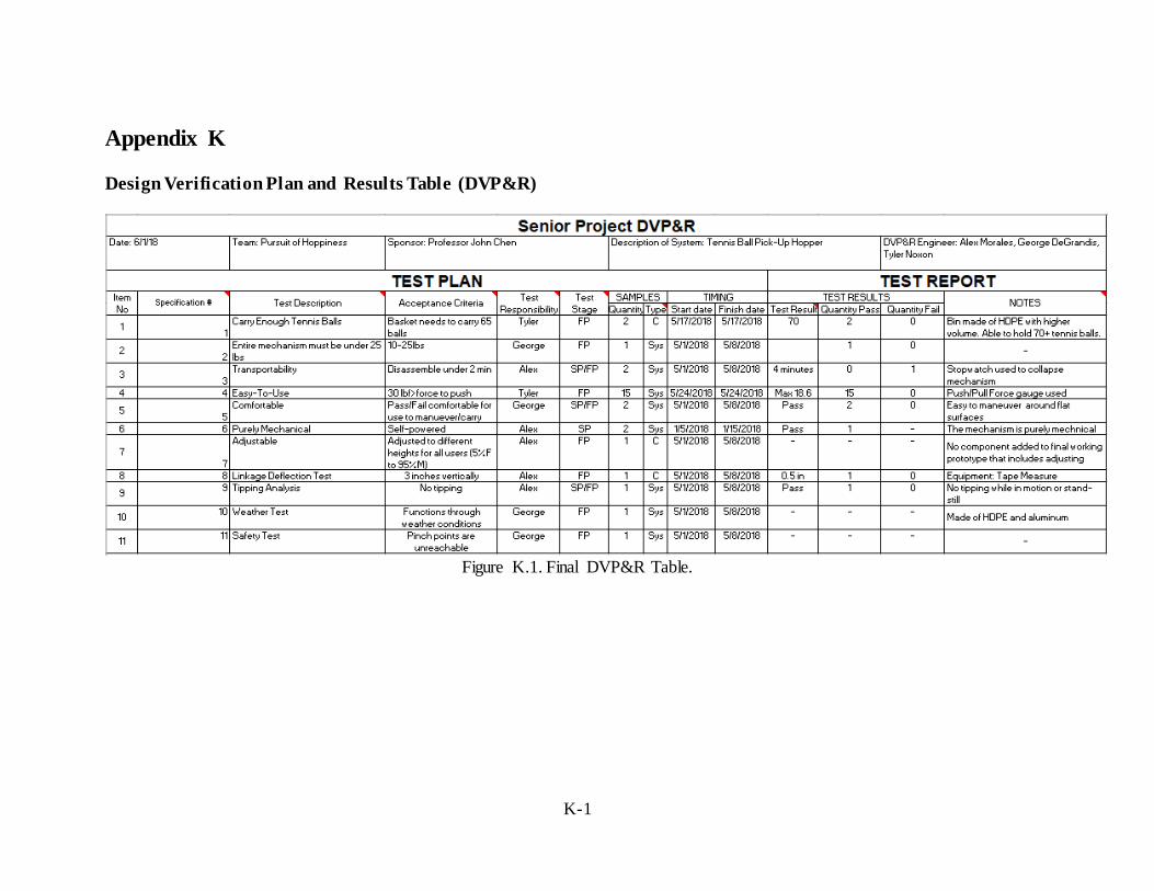
K-1
Appendix K
Design Verification Plan and Results Table (DVP&R)
Figure K.1. Final DVP&R Table.

L-1
Appendix L
Operators' Manual
Paddlewheel Mechanism This user’s manual includes instructions for product use and safety information. Read this section entirely including all safety warnings and cautions before using the product.
Important: This mechanism is meant for use on a tennis court by tennis players of all ages.
Before using this product, the user should be familiar with the operation and safety risks.
Warning: Do not use product while other players are engaged in a match.
The following instructions include everything you need to know to collapse the Paddlewheel
Mechanism for ease of transportability.
Collapsing the Paddlewheel
Tools Required: Two (7/16)" wrenches Follow these directions to collapse the Paddlewheel Mechanism.

L-2
1) Unlock the two spring-loaded pins from both sides of the mechanism and raise the bin up
until it locks into the second hole or is parallel to the ground
a. Note: Currently, the product needs the assistance of two individuals to unlock the
pins and raise the bin. The plan for future advancement, is to have one locking pin
that is enabled through a cable pull system.
2) Remove nuts and bolts from upper handle to collapse and move the ramp toward and
over the paddles.
a. Note: Two bolts and nuts on both sides connect the handles and upper linkages.
The upper two bolts and nuts are to be removed in this step.

L-3
3) Loosen bolts from the front side pieces to move the front subassembly inward.
Caution: As the user is lowering the bin, make sure there is no one under the bin as this could lead to injury.
4) Unlock the spring-loaded pins from both side of the mechanism and lower the bin up
onto the ramp.

L-4
Tips for Operation
Caution: The user should be familiar with all safety concerns of using the Paddlewheel
Mechanism. The Paddlewheel Mechanism has pinch points around the paddles that can injure the user or a non-user if a hand is near the paddles while in motion. Misuse of the Paddlewheel Mechanism could injure people or damage the product.
To use the Paddlewheel Mechanism, simply maneuver the mechanism around the tennis court to
collect tennis balls. Move the Paddlewheel Mechanism over the tennis balls to collect them. The user should be aware of the functions of the Paddlewheel Mechanism when in use. Currently, the mechanism picks up tennis balls effectively. At times, a tennis ball or two will jam. To move
around this problem, simply move backwards and attempt to collect the tennis ball again. A recommended walking speed of 3 ft/s will maximize the efficiency of the product.
When the bin is full, the user will disengage the spring-loaded pins and push down on the handles to lift the bin up to the desired height. It is important to note that at this stage of building the working prototype, the lifting of the basket requires a minimum of two individuals.
Caution: As the user pushes down on the handle to lift the bin, the Paddlewheel mechanism tends to lift from the front of the prototype. It is advised to do this procedure with two individuals as the tipping of the mechanism can cause injury to the user or players nearby.
Maintenance No active maintenance is required to keep the Paddlewheel working efficiently. The Paddlewheel mechanism is water resistant and is used outdoors but should not be left outside standing in water
or sitting in the sun. It should also not be exposed to extreme heat.
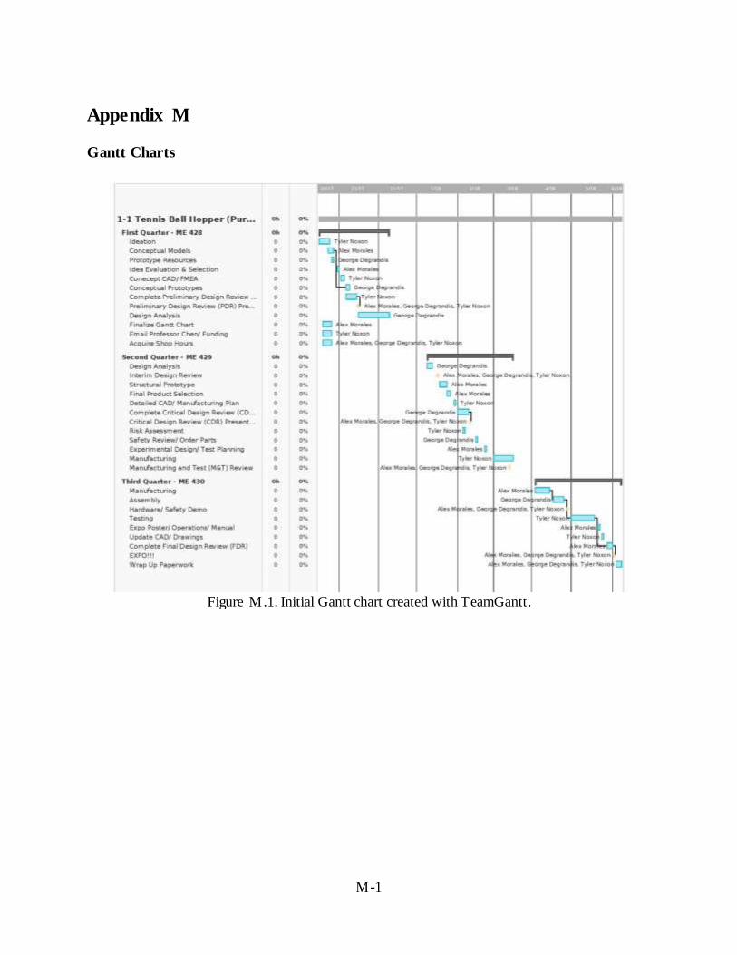
M-1
Appendix M
Gantt Charts
Figure M.1. Initial Gantt chart created with TeamGantt.

M-2
Figure M.2. Updated Gantt chart with weekly tasks through first quarter.
Figure M.3. Updated Gantt chart for second quarter with weekly tasks through CDR.

M-3
Figure M.5. Updated Gantt Chart for Third Quarter Through Final Design Review.