lightweight water purification system (lwps)marinecorpswater.com/student guide_lwps ops _revised...
TRANSCRIPT

0
TerraGroup Corporation
Lightweight Water Purification System
(LWPS) Operation And Maintenance Student Guide
Tactical Water Purification Systems TECWAR® SYSTEMS
This handout is designed to serve as a training aid during training on the Lightweight Purification System. This information is furnished upon the condition that it will not be released to another nation without the specific authority of Primo L. Acernese, that it will be used for military purposes only, that individual or corporate rights originating in the information, whether patented or not, will be respected, that the recipient will report promptly to the United States any known or suspected compromise.

pg. 1
TABLE OF CONTENTS
OPERATION OF LWPS UNDER USUAL CONDITIONS ......................................................... 4
Site Selection, Unpacking And Setup Of The LWPS .......................................................... 4
Floating Intake Strainer And Ocean Intake Structure System (OISS) Setup .......................... 5
Initial Start Up .......................................................................................................... 5
Manual Start Raw Water Pump Module Engine ........................................................... 6
Electrical Start Raw Water Pump Module Engine ........................................................ 6
Manual/Electrical Start High-Pressure Pump Module Engine. ...................................... 7
LWPS Mission Normal Product Flow Rates ................................................................. 7
Chlorine Injection/Direct Product Water To Storage .................................................... 8
Military Field Water Quality Standards ..................................................................... 9
Potable Water Distribution .................................................................................... 10
SYSTEM MONITORING AND TESTING ......................................................................... 10
Normal Pressure Readings During Operation .............................................................. 11
Flow Meter Readings ............................................................................................... 11
WATER TESTING ....................................................................................................... 12
SHUTDOWN SYSTEM TO STAND-BY ............................................................................. 12
SYSTEM MAINTENANCE ............................................................................................ 13
Purging The Separator ............................................................................................. 13
Backwashing Procedures ......................................................................................... 14
LONG TERM SYSTEM SHUTDOWN ............................................................................... 15
Product Water Flush ................................................................................................ 15
CLEANING REVERSE OSMOSIS (RO) MEMBRANES ..................................................... 16
RO Element Cleaning Setup ................................................................................... 16
RO Element Cleaning Procedures (High Ph)( Tergajet) .............................................. 17

pg. 2
Ro Element Cleaning Procedures (Low Ph)( Citric Acid) ............................................. 18
System Preservation ............................................................................................. 19
OPERATION OF LWPS UNDER UNUSUAL CONDITIONS ................................................... 20
Chlorinated Water Source ......................................................................................... 20
High Turbidity Water Source ..................................................................................... 21
Coagulant Dosage Chart ....................................................................................... 21
NUCLEAR, BIOLOGICAL, AND CHEMICAL (NBC) CONTAMINATED WATER SOURCE ..... 22
Securing LWPS For NBC Attack .............................................................................. 22
Decontamination Of LWPS .................................................................................... 22
COLD WEATHER OPERATIONS ................................................................................ 23
PERIODIC PREVENTIVE MAINTENANCE CHECKS AND SERVICES (PMCS), INCLUDING
LUBRICATION INSTRUCTIONS .................................................................................... 24
PREPARATION FOR STORAGE .................................................................................... 33
Load LWPS Components On QUADCON
Pallet…………………………………..………………………33
Load LWPS Components On QUADCON Pallet/ Load
QUADCON………….…………………………35
Load LWPS Components On HMMWV…………………………………….…………………………38
Load LWPS Components On LTT-H…………………………………………….…………………………39
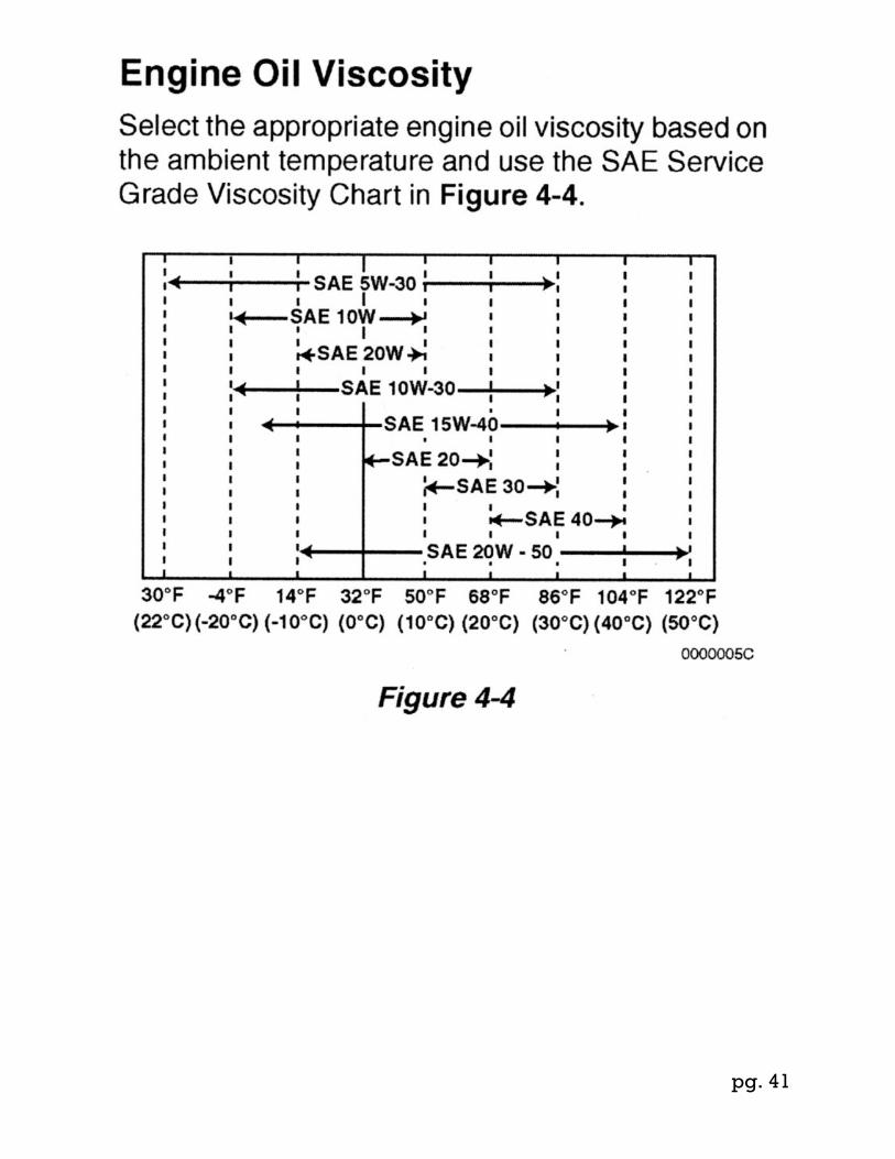
ENGINE OIL VISCOSITY.……………………………………………..……………………………………….
40
HIGH PRESSURE PUMP MODULE LUBRICATION
REQUIREMENT…………….……………...……..41
LWPS DATA LOG………………………………………………………..………………………………………42

pg. 3
This page is blank

pg. 4
OPERATION OF LWPS UNDER USUAL CONDITIONS
SITE SELECTION, UNPACKING AND SETUP OF THE LWPS
NOTE REFER TO TM 11720A-OI PAGES 0005-01 THRU 0005-29 AND FOLDOUT (FO-1 AND FO-2) LWPS QUICK START CHARTS FOR SITE SELECTION, UNPACKING AND SETUP OF THE LWPS

pg. 5
1. Test raw water source for high turbidity and presence of chlorine. Refer to System Monitoring and Testing in this student guide for instructions.
NOTE The 1,000-gallon raw water tank is designed to be used only when raw water source is chlorinated or has high turbidity. Refer to WP 0006 for 1,000-gallon raw water tank setup and use procedures. 2. If raw water source has high turbidity or is chlorinated, set up 1,000-gallon raw water tank. Refer to High Turbidity Water Source or Chlorinated Water Source in in this student guide for instructions
FLOATING INTAKE STRAINER AND OCEAN INTAKE STRUCTURE SYSTEM (OISS) SETUP
NOTE Refer to TM 11720A-OI pages 0005-30 thru 0005-38 for FLOATING INTAKE STRAINER and OCEAN
INTAKE STRUCTURE SYSTEM (OISS) SETUP, USE AND PROCEDURES
INITIAL START UP
WARNING • DO NOT overfill pump fuel tank. Ensure filler cap is securely closed after fueling. Always add fuel to diesel engine in well-ventilated area with engine stopped. DO NOT smoke or allow flames or sparks in area where engine is fueled or where fuel is stored. • Prior to operating the LWPS, verify that all high-pressure hose connections are secure and the reject water control valve is fully opened. • Ear protection should be worn when operating the LWPS. Failure to follow this warning may result in hearing loss to personnel. • A fire extinguisher must be placed a minimum of 25 foot from the LWPS during operation. • Failure to follow these warnings may result in injury or death to personnel.
NOTE Prior to operating the LWPS, perform all before PMCS procedures.
1. Verify the following conditions: a. Drain petcock valve of raw water and product water pump modules are closed. b. Separator drain valve on strainer/separator module is closed. c. Media filter control valves on both media/cartridge filter modules are set to the filtration position. d. Media filter vessel drain on both media/cartridge filter modules are closed. e. Reject water control valve on RO module is fully opened. f. Chlorine injection bypass control lever on chlorinator is in the OFF position. g. Product water discharge hose disconnected from 3,000-gallon product water tank.
NOTE If necessary, tip raw water pump module slightly to allow water to be poured into the pump outlet
fitting when priming pump. 2. Prime the raw water pump module by pouring water directly into either pump outlet fitting with the priming pitcher.

pg. 6
3. Manual starting raw water pump Start raw water pump module engine -: a. Place fuel shutoff valve in the open position by rotating the valve handle clockwise down. b. Place throttle control handle in the full throttle position by pressing pushbutton and raising handle fully. c. Slowly pull the recoil starter handle until resistance is met. d. Place red compression release handle in the released position. e. Slowly pull the recoil starter handle until the compression release is automatically returned.
NOTE New engines or engines that have been stored for long periods may require as many as six or
more slow pulls of recoil starter to prime engine and remove air from fuel injector line. f. Repeat steps c through e several times to prime fuel injector. g. Once engine is primed, place red compression release handle in the released position, and pull the recoil starter handle to start engine. h. If engine fails to start, refer to step 4 and use the electric starter to start engine.
4. Electric starting - Start raw water pump module engine -: a. Place fuel shutoff valve in the ON position by rotating the valve handle clockwise down. b. Place throttle control handle in the full throttle position by raising handle fully. c. Connect NATO slave adapter cable to NATO slave adapter receptacle. d. Connect NATO slave adapter cable to 24-volt power source. e. Verify green starter switch illumination, indicating power is available. f. Press starter switch and hold until engine starts. g. If engine fails to start after 30 seconds, release starter switch, and allow starter to cool for 2 minutes before next attempt. h. Once engine starts, remove 24-volt power source, and disconnect NATO slave adapter cable.

pg. 7
START UP-CONTINUED NOTE
If pump does not maintain prime, stop engine, and inspect raw water intakes, check valve, and hoses for debris and proper connection. Verify connection gaskets are free of sand and dirt.
5. Slightly open air vent valve on strainer/separator module to bleed air from raw water stream. Close valve when water discharge shows no signs of air. 6. Briefly open separator drain to remove any accumulated sand and dirt from separator. Close drain when discharge from waste water discharge hose is clean.
NOTE Adjusting throttle control on the raw water pump module will regulate pressure and flow through
the strainer/separator module and media/cartridge filter modules. 7. Monitor the pressure gauges on the raw water pump module, strainer/separator module and media/cartridge filter modules. Pressure readings should be approximately the same for all modules, and should not exceed 45 psi.
NOTE The engine controls on the High-Pressure Pump Module are identical to the engine controls on
the raw water pump module.
8. Refer to steps 3 and 4, and start high-pressure pump module engine. 9. Verify readings on strainer/separator module flow meter and RO module flow meter. Readings should be approximately 8 – 10 GPM.
WARNING NEVER exceed 1,000 psi as indicated on the high-pressure pump module outlet pressure gauge
Failure to follow this warning may result in injury to personnel or damage to equipment.
CAUTION Open and close the RO reject water control valve slowly (60 seconds). Failure to follow this
caution may result in damage to equipment. 10. Slowly close the RO reject water control valve to increase pressure in the RO vessels while observing the high-pressure pump module outlet pressure gauge.
NOTE
LWPS Mission Normal product flow rates are as follows: Saltwater sources 15,000 ppm or above 1.25 GPM Brackish/freshwater sources below 15,000 ppm 2.1 GPM
Product flow rates are based on optimal performance of RO elements and should be exceeded only when push limits are required
pg. 8
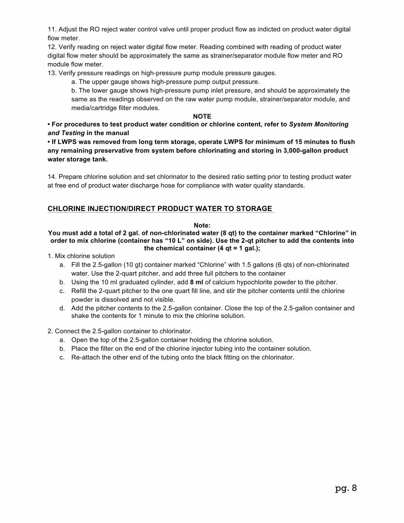
11. Adjust the RO reject water control valve until proper product flow as indicted on product water digital flow meter. 12. Verify reading on reject water digital flow meter. Reading combined with reading of product water digital flow meter should be approximately the same as strainer/separator module flow meter and RO module flow meter. 13. Verify pressure readings on high-pressure pump module pressure gauges.
a. The upper gauge shows high-pressure pump output pressure. b. The lower gauge shows high-pressure pump inlet pressure, and should be approximately the same as the readings observed on the raw water pump module, strainer/separator module, and media/cartridge filter modules.
NOTE • For procedures to test product water condition or chlorine content, refer to System Monitoring and Testing in the manual • If LWPS was removed from long term storage, operate LWPS for minimum of 15 minutes to flush any remaining preservative from system before chlorinating and storing in 3,000-gallon product water storage tank. 14. Prepare chlorine solution and set chlorinator to the desired ratio setting prior to testing product water at free end of product water discharge hose for compliance with water quality standards.5
CHLORINE INJECTION/DIRECT PRODUCT WATER TO STORAGE 0005
Note: You must add a total of 2 gal. of non-chlorinated water (8 qt) to the container marked “Chlorine” in order to mix chlorine (container has “10 L” on side). Use the 2-qt pitcher to add the contents into
the chemical container (4 qt = 1 gal.); 1. Mix chlorine solution
a. Fill the 2.5-gallon (10 gt) container marked “Chlorine” with 1.5 gallons (6 qts) of non-chlorinated water. Use the 2-quart pitcher, and add three full pitchers to the container
b. Using the 10 ml graduated cylinder, add 8 ml of calcium hypochlorite powder to the pitcher. c. Refill the 2-quart pitcher to the one quart fill line, and stir the pitcher contents until the chlorine
powder is dissolved and not visible. d. Add the pitcher contents to the 2.5-gallon container. Close the top of the 2.5-gallon container and
shake the contents for 1 minute to mix the chlorine solution.
2. Connect the 2.5-gallon container to chlorinator. a. Open the top of the 2.5-gallon container holding the chlorine solution. b. Place the filter on the end of the chlorine injector tubing into the container solution. c. Re-attach the other end of the tubing onto the black fitting on the chlorinator.

pg. 9
NOTE • The chlorinator is designed to inject a solution at the same set ratio regardless of fluid flow, using a hydraulically controlled piston. • The chlorinator should inject the required parts per million (ppm) of chlorine into the product water flow stream, regardless of how much product water the LWPS is producing. • Using the chlorine injector, with the 500:1 ratio, you will use about 2 gallons (8 qts) of chlorine solution in 8 hours if the LWPS is producing product water at a flow rate of 2.1 GPM. 3. Ensure chlorinator is set to the desired ratio setting or free chlorine residual by aligning the small white line in the ratio-indicating cylinder. Turn the ratio-indicating cylinder to adjust the chlorine injection ratio.
Injector Setting Chlorine Residual 500:1 2 ppm 250:1 3.5 ppm 165:1 5 ppm
4. Move the chlorine injection bypass control lever on top of chlorinator to the ON position. 5. Test product water at free end of product water discharge hose for purity and chlorine content.
NOTE For procedures to test product water condition or chlorine content, refer to test equipment manual
NOTE
• According to TB MED 577/NAVMED P-5010-10/AFMAN 48-138_IP, the following MUST be checked and confirmed prior to storage (Tables 4-2 and 4-4; May 2010):
Military Field Water Standards
Short-term potability military field water Standards (30-day)
Long-term potability military field water standards (>30 days)
TDS 1000 ppm TDS 500 ppm PH 5 – 9 pH units PH 6.5-8.5 pH units Turbidity 1 NTU Turbidity 1 NTU Chlorine Residual 2 ppm Chlorine Residual 2 ppm 6. When water quality has been confirmed, data should be recorded in the LWPS Data Log. Data Log examples can be found in WP 0053, LWPS Data Logs.
7. Verify that ball valve on inlet side of 3,000-gallon product water storage tank is open, and ball valve on outlet side of 3,000-gallon product water storage tank is closed. 8. Connect 1 inch x 10 foot product water discharge hose to the 1 to 2 inch adapter on side of 3,000-gallon product water storage tank. 9. Fill the 3,000-gallon product water storage tank to capacity.

pg. 10
POTABLE WATER DISTRIBUTION 000 5 1. Open ball valve on outlet side of 3,000-gallon product water storage tank, and allow water to gravity feed to product water pump module.
NOTE • The engine controls on the product water pump module are identical to the engine controls on the raw
water pump module. • Ensure distribution line has been flushed for 30 seconds prior to distributing water to consumers. 2. Start product water pump module engine. 3. Use product water pump’s throttle control to regulate pressure and flow through the product water distribution nozzles. 4. Dispense potable water as needed. The system has the capability to dispense water from both distribution nozzles simultaneously.
SYSTEM MONITORING AND TESTING 0005
NOTE • During operation, data obtained by monitoring or testing the system should be recorded in the LWPS Data Log. Data log examples can be found in WP 0053, LWPS Data Logs. • Information recorded in LWPS Data Log is to be used as a reference for performing maintenance and troubleshooting. This section provides information on monitoring the LWPS during operations and testing raw and product waters to determine water condition. System Monitoring 00 05 Several components are provided to monitor the LWPS during water production. Gauges provide instant verification of system pressures, while flow meters indicate water flow throughout the system. Gauges can also provide an indication of problems during operation. A pressures difference between modules or module components is usually an indication of a plugged strainer, media filter, or cartridge filter and requires immediate attention. Flow meters can alert the operator to reduction of flow within the system. Differences in flow meter readings can indicate a leaking or failed component, as well as damaged or fouled RO Membranes.
1. There are three types of gauges used on the LWPS: Low-Pressure; High-Pressure; And Temperature. a. Low-Pressure Gauges include the Raw Water Pump Module; Strainer/Separator Module and both Media/Cartridge Filter Modules, consisting of the media filter gauge and the cartridge filter gauge. The table below shows normal pressure readings expected during operation.
b. High-Pressure Gauges include the high-pressure pump module, consisting of the pump outlet pressure gauge and the pump inlet pressure gauge and the Reject Water Control Valve Gauge. The pump inlet pressure gauge should reflect pressures indicated on the low-pressure gauges. The pressures shown on the pump outlet gauge and the reject water control valve gauge are dependent on how much

pg. 11
pressure is applied to the RO Membranes as controlled by the RO reject water control valve. The more the valve is closed, the higher the pressure and the higher the product water output flow. The table below shows normal pressure readings expected during operation.
Normal Pressure Readings during Operation PRESSURE GAUGE NORMAL READING PROBLEM INDICATED
Raw Water Pump Module 25 to 45 psi Under 25 or over 45 psi Strainer/Separator Module 25 to 45 psi Under 25 or over 45 psi Media Filter (Module 1 or 2) 25 to 45 psi Under 25 or over 45 psi Cartridge Filter (Module 1 or 2) 25 to 45 psi Under 25 or over 45 psi High-Pressure Pump Inlet 25 to 45 psi Under 25 or over 45 psi High-Pressure Pump Outlet 250 to 1,000 psi Above 1,000 psi Reject Water Control Valve 250 to 925 psi Above 950 psi Strainer/Separator Temperature Above 75ºF N/A
2. There are two types of flow meters used with the LWPS: Analog Flow Meters (in system) and Digital Flow Meters (output flow).
a. Analog Flow Meters include the Strainer/Separator Module flow meter located between the strainer and separator; and the RO flow meter located on the number 1 RO vessel inlet fitting. During normal operations, both analog flow meters should display similar readings. The table below shows normal flow readings expected during operations. b. Digital Flow Meters include the reject water flow meter and the product water flow meter. The digital flow meters turn on automatically whenever flow is detected or manually by pressing the display button. The digital flow meters turn off automatically when there is no flow detected for 1 minute. The Reject flow meter has ¾ inch fittings and a flow rate of 20 GPM; the Product flow meter has ½ inch fittings and a flow rate of 10 GPM. The digital flow meters display flow, batch, and cumulative totals. Except for fitting size and flow rate both digital flow meters are operationally identical. c. Under normal circumstances, the sum of both digital flow meters should reflect the same readings as taken from either analog flow meter. Digital flow meter readings are dependent on the ratio of product water to reject water (i.e., higher product water flow equals lower reject water flow). The table below shows normal flow readings expected during operations.
NOTE
Refer to step 4 for digital flow meter operating procedures.
NOTE Normal reject water flow will reflect system flow with zero product water flow. Normal product water flow will reflect system flow minus reject water flow. If sum of reject water and product water flow is vastly different than system flow, a problem may be indicated in the RO elements.
Flow Meter Readings. 00
FLOW METER NORMAL READING PROBLEM INDICATED Strainer/Separator Flow Meter 8 to 20 GPM Below 8 GPM RO Module Flow Meter Up to 8 GPM Below 8 GPM Reject Water Digital Flow Meter Up to 8 GPM Below 5 GPM See Note Product Water Digital Flow Meter Up to 2.5 GPM Over 3 GPM See Note
3. Monitor system pressure gauges and flow meters during operation to ensure safe water production and minimize maintenance. 4. Operate digital flow meters using the following procedures:

pg. 12
a. Flow Rate is accessed by briefly pressing and releasing DISPLAY button. When this feature is activated, “FLOWRATE” is displayed on left side of bottom line, and numbers in middle of display reflect rate of flow. The display is set to update display every 5 seconds. b. Cumulative Total is accessed by briefly pressing and releasing DISPLAY button. Cumulative Total is indicated by “TOTAL 1 LOCKED” on the bottom line, and numbers in middle of display reflect total of all water measured since last battery change. Cumulative Total is labeled as LOCKED, indicating that it cannot be manually zeroed. Cumulative Total can be cleared only when batteries are expired or removed, or when Cumulative Total reaches maximum value of 999,999. c. Batch Total is accessed by briefly pressing and releasing DISPLAY button. Batch Total is indicated by “TOTAL 2” on the bottom line, and numbers in middle of display reflect total of all water measured since start of current operational cycle, which zeros after flow ceases. Batch Total register may be manually cleared to “0.00” at any time. To clear Batch Total, press and hold DISPLAY button for 3 seconds, at which time displayed total is cleared to “0.00.” Total can be cleared even while water is flowing, in which case counting resumes after DISPLAY button is released. d. Switching from GAL to LTH Modes. Switching from GAL to LTH modes is accomplished by pressing and holding the CALIBRATE button. Continue holding CALIBRATE button while also briefly pressing and releasing the DISPLAY button. Then release the CALIBRATE button
WATER TESTING 005 Raw water must be tested to determine levels of contaminates and chlorine present. Excessive contaminates (high turbidity) can quickly foul filters and RO Membranes, requiring higher than normal maintenance and cleaning cycles. The presence of chlorinated water can cause irreparable damage to the RO Membranes. Water that displays high turbidity (above 75 NTU) or chlorine requires use of the 1,000-gallon raw water tank for treatment before water production can begin. Product water can be tested at the individual RO vessels to measure contamination levels and determine if a RO Membrane requires replacement. Product water can also be tested at the distribution point to verify purity and correct chlorine levels (correct chlorinator settings). For testing of water quality, refer to TB-MED-577/NAVMED P-5010-10/AFMAN 48-138_1P and TM 10-6630-222-12&P.
STAND-BY SYSTEM SHUTDOWN 0005 CAUTION
Always open and close the RO reject water control valve very slowly. Opening or closing the RO reject water control valve too quickly can create pressure spikes within the RO module vessels, damaging the RO Membranes. Failure to follow this caution may result in damage to equipment.
1. Slowly open the RO reject Control valve until RO inlet psi gauge lowers and then steadies. 2. Shut down high-pressure pump module engine by pushing throttle handle down until engine stops. 3. Idle down raw water pump module engine by pushing throttle handle down until engine reaches idle. 4. Fully open separator drain valve on strainer/separator module to relieve any remaining system pressure.

pg. 13
SYSTEM MAINTENANCE
PURGING THE SEPARATOR The Cyclone Separator must be purged regularly to remove the separated solids from the temporary collection chamber.
NOTE Perform this procedure
• Every 2 hours when operating under usual conditions • Every 1 hour when operating on a highly turbid source or on the beach
Evacuation of separated solids shall be accomplished by: 1. Determine current system pressure by observing the needle on the media filter gage. The normal system pressure is 25 to 45 psi. If not within the normal operational range refer to troubleshooting
WARNING While performing this procedure do not allow the system pressure to drop below 25 psi as observed on the media filter gauge. Failure to follow this warning may result in damage to
equipment. 2. Slowly open the separator drain valve (item 3) while observing media filter gauge
Strainer/Separator Module 3. Wait 15-20 seconds or when discharge from separator waste hose is clear (whichever comes first) 4. Close the separator drain valve 5. Verify readings on strainer/separator module flow meter (Item 1) and RO module flow meter readings should be approximately the same at (or around) 8 GPM. 6. Continue normal operations END OF TASK
3
1

pg. 14
BACKWASHING PROCEDURES 0005 Backwashing procedures are utilized to clean the granular filter media of contaminates and debris, extending the life of the filter. Perform backwashing procedures for any of the following conditions: • When media filter gauge on the media/cartridge filter module displays over 45 psi, while the remaining system gauges read normal. • When there is a difference between pressure gauge readings of 10 to 15 psi from initial operating pressure reading. • At least once a day, if operating from rivers, lakes or sources with substantial organic matter. • After completion of mission or in preparation for long term storage. After completion of backwashing procedures, operate LWPS normally.
WARNING During backwashing procedures, continuously monitor flow meters and gauges. DO NOT exceed
15 GPM flow or 45 psi. Failure to follow this warning may result in injury or death to personnel and damage to equipment.
NOTE
Water production must be stopped before starting backwashing procedures. Ensure reject water control valve is fully opened and high-pressure pump is stopped before continuing.
1. Slowly open the reject water control valve fully to stop water production. 2. Shut down high-pressure pump by pushing throttle handle down until engine stops. 3. Throttle back raw water pump module engine by rotating throttle handle clockwise until engine slows to idle. 4. Fully open separator drain valve on strainer/separator module to relieve raw water pressure.0005 5. Push down and turn control handle on first media filter head to backwash position. 6. Push down and turn control handle on second media filter head to closed position. 7. Fully close separator drain valve on strainer/separator module. 8. Advance throttle on the raw water pump engine until engine rpm is sufficient to maintain 13 to 15 GPM indicated flow on strainer/ separator module flow meter. 9. Backwash media filter for minimum 10 minutes.
NOTE Occasionally check media filter site glass bottle for media buildup. If excessive media is visible in
site glass bottle or waste water discharge hose, reduce raw water pressure throttling back raw water pump module engine.
10. Periodically check media filter site glass bottle and waste water discharge hose for water clarity. 11. After backwash is complete, throttle back the raw water pump module engine by rotating throttle handle clockwise until engine slows to idle. 12. Fully open separator drain valve on strainer/separator module to relieve raw water pressure. 13. Push down and turn control handle on first media filter head to rinse position. 14. Fully close separator drain valve on strainer/separator module. 15. Advance throttle on the raw water pump engine until engine rpm is sufficient to maintain 13 to 15 GPM indicated flow on strainer/ separator module flow meter. 16. Rinse media filter for minimum 5 minutes. 17. After rinse is complete, throttle back the raw water pump module engine by rotating throttle handle clockwise until engine slows to idle. 18. Fully open separator drain valve on strainer/separator module to relieve raw water pressure. 19. Push down and turn control handle on second media filter head to backwash position. 20. Push down and turn control handle on first media filter head to closed position. 21. Repeat steps 5 through 16 to backwash second media filter. 22. After backwash procedures are completed, return both media filter control handles to filtration position. 23. Continue with normal operating procedures, or shut down system, if necessary. END OF TASK
pg. 15
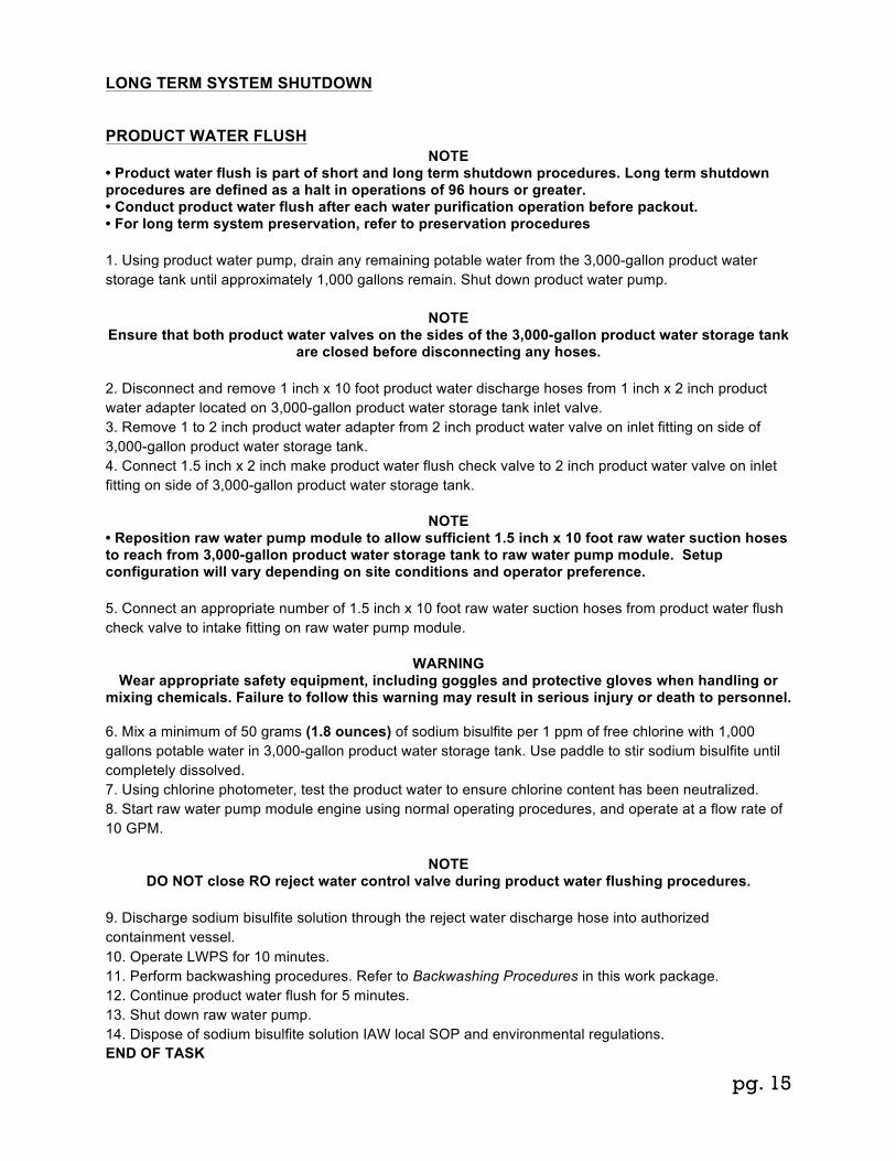
LONG TERM SYSTEM SHUTDOWN
PRODUCT WATER FLUSH 0005 NOTE
• Product water flush is part of short and long term shutdown procedures. Long term shutdown procedures are defined as a halt in operations of 96 hours or greater. • Conduct product water flush after each water purification operation before packout. • For long term system preservation, refer to preservation procedures 1. Using product water pump, drain any remaining potable water from the 3,000-gallon product water storage tank until approximately 1,000 gallons remain. Shut down product water pump.
NOTE Ensure that both product water valves on the sides of the 3,000-gallon product water storage tank
are closed before disconnecting any hoses.
2. Disconnect and remove 1 inch x 10 foot product water discharge hoses from 1 inch x 2 inch product water adapter located on 3,000-gallon product water storage tank inlet valve. 3. Remove 1 to 2 inch product water adapter from 2 inch product water valve on inlet fitting on side of 3,000-gallon product water storage tank. 4. Connect 1.5 inch x 2 inch make product water flush check valve to 2 inch product water valve on inlet fitting on side of 3,000-gallon product water storage tank.
NOTE • Reposition raw water pump module to allow sufficient 1.5 inch x 10 foot raw water suction hoses to reach from 3,000-gallon product water storage tank to raw water pump module. Setup configuration will vary depending on site conditions and operator preference. 5. Connect an appropriate number of 1.5 inch x 10 foot raw water suction hoses from product water flush check valve to intake fitting on raw water pump module. 0005
WARNING Wear appropriate safety equipment, including goggles and protective gloves when handling or
mixing chemicals. Failure to follow this warning may result in serious injury or death to personnel.
6. Mix a minimum of 50 grams (1.8 ounces) of sodium bisulfite per 1 ppm of free chlorine with 1,000 gallons potable water in 3,000-gallon product water storage tank. Use paddle to stir sodium bisulfite until completely dissolved. 7. Using chlorine photometer, test the product water to ensure chlorine content has been neutralized. 8. Start raw water pump module engine using normal operating procedures, and operate at a flow rate of 10 GPM.
NOTE
DO NOT close RO reject water control valve during product water flushing procedures.
9. Discharge sodium bisulfite solution through the reject water discharge hose into authorized containment vessel. 10. Operate LWPS for 10 minutes. 11. Perform backwashing procedures. Refer to Backwashing Procedures in this work package. 12. Continue product water flush for 5 minutes. 13. Shut down raw water pump. 14. Dispose of sodium bisulfite solution IAW local SOP and environmental regulations. END OF TASK

pg. 16
CLEANING REVERSE OSMOSIS (RO) MEMBRANES 0005 In normal operation, the membranes in RO elements can become fouled by suspended solids, microorganisms, and mineral scale. These deposits build up during operation and cause loss in water output, salt rejection, or both. The Marine in Field Cleaning Element Extension (MICEE) kit is used to flush the RO membranes and remove deposit buildup, thereby extending the life of the RO Membranes. Fifteen gallons of neutralized product water will be used per RO cleaning/flushing and per RO preservation cycles. RO Membranes should be cleaned when: • Normalized water output rate drops by 15% from initial flow rate (flow rate is established during first 24 to 48 hours of operation). • Salt content of product water exceeds 1,000 ppm. • System operating pressure reaches 1,000 psi.
RO ELEMENT CLEANING SETUP 0005 1. Fully open separator drain valve on strainer/separator module to relieve any system pressure. 2. Remove U-connector from media filter outlet and cartridge filter inlet on second media/cartridge filter module. 3. Connect MICEE kit 1 inch x 10 foot cleaning hose to the cartridge filter inlet on the second media/cartridge filter module. 4. Remove RO reject water control valve from high-pressure outlet port on No. 4 RO vessel. 5. Connect the cleaning adapter to high-pressure outlet port on No. 4 RO vessel. 6. Connect other end of 1 inch x 10 foot cleaning hose to the cleaning adapter on No. 4 RO vessel. 7. Remove 1 inch x 5 foot high-pressure pump suction hose from pump inlet fitting on high-pressure pump module. 8. Remove 1 inch x 3 foot cartridge filter discharge hose and 1 inch x 5 foot high-pressure suction hose on bottom of cartridge from outlet fitting on bottom of cartridge filter housing on second media/cartridge filter module. 9. Position the MICEE kit cleaning bag on ground near high-pressure pump module and second media/cartridge filter module. 10. Connect 1 inch x 5 foot cleaning hose to outlet fitting on bottom of cartridge filter housing on second media/cartridge filter module, and other end to inlet tee fitting on cleaning bag. 11. Connect 1 inch x 5 foot cleaning hose to outlet fitting on cleaning bag. Connect the end of hose to pump inlet fitting on high-pressure pump module.0005 12. Remove plug located on inlet tee fitting of cleaning bag. Install fabric funnel to in inlet tee fitting

pg. 17
RO ELEMENT CLEANING PROCEDURES (HIGH pH)( TERGAJET) 1. Flush chemical mixing container with product water to remove any residual chemicals. 2. Using chemical mixing container, fill cleaning bag with 13 gallons of product water. 3. Mix 2.9 pounds (1,315 grams/ml) (46.5 ounces) of high pH cleaner agent with 2 gallons of non-chlorinated product water in chemical mixing container until completely dissolved. Add solution to water in cleaning bag and mix contents. 4. Remove fabric funnel and install plug in inlet tee fitting Agitate cleaning bag to mix contents.
CAUTION Approximately 75 Gallons of non-chlorinated water will be required to perform RO element cleaning. • Ensure sufficient water level is present in cleaning bag, to avoid operating the high-pressure pump with an insufficient feed flow. • While flushing, the operator must continually be aware of the water level in the cleaning bag. • Failure to follow these cautions may result in damage to equipment.
5. Start high-pressure pump module engine using normal procedures, and adjust throttle to maintain approximately 8 GPM as indicated on RO module flow meter. 0005 6. Circulate cleaning solution for a minimum of 90 minutes. 7. Shut down high-pressure pump module engine using normal procedures. 8. Remove plug from bottom of cleaning bag and drain cleaning bag into a suitable container. Flush bag with product water. Dispose of solution IAW local SOP and environmental regulations. Install plug in bottom of cleaning bag. 9. Flush chemical mixing container with product water to remove any residual chemicals remaining. 10. Remove plug and install fabric funnel in inlet tee fitting on cleaning bag
CAUTION The high pH cleaning agent (Tergajet) should be flushed from the system prior to low ph cleaning or damage could occur to the RO membranes. Failure to follow this caution may result in damage
to equipment.
11. Using chemical mixing container, fill cleaning bag with 15 gallons of product water. Remove fabric funnel and reinstall plug on cleaning bag inlet tee. 12. Disconnect 1 inch x 5 foot cleaning hose from inlet tee fitting on cleaning bag. Direct cleaning hose into a suitable container. 13. Start high-pressure pump module engine using normal procedures, and adjust throttle to maintain approximately 8 GPM as indicated on RO module flow meter.
CAUTION Carefully monitor the cleaning bag to avoid running bag dry and interrupting pump inlet feed flow.
Failure to follow this caution may result in damage to equipment. 14. Monitor cleaning bag. Shut down high-pressure pump module engine using normal procedures once the cleaning bag nears empty. 15. Drain remaining cleaning solution from cleaning bag into container and dispose of solution IAW local SOP and environmental regulations. 16. Connect 1 inch x 5 foot cleaning hose to inlet tee fitting on cleaning bag. 17. Using chemical mixing container, fill cleaning bag with 13 gallons of product water.
WARNING Wear appropriate safety equipment, including goggles and protective gloves when handling or
mixing chemicals. Failure to follow this warning may result in serious injury or death to personnel.

pg. 18
RO ELEMENT CLEANING PROCEDURES (LOW pH)( CITRIC ACID) 18. Mix 1.15 pound (521 grams/ml) (18.5 ounces) low PH (Citric Acid) cleaning agent with 2 gallons water in chemical mixing container until completely dissolved. Add solution to water in cleaning bag. 19. Remove fabric funnel and install plug in inlet tee fitting, and agitate cleaning bag to mix contents. 20. Start high-pressure pump module engine using normal procedures, and adjust throttle to maintain approximately 8 gpm as indicated on RO module flow meter. 21. Operate MICEE kit system for minimum 30 minutes. 22. Shut down high-pressure pump module engine using normal procedures. 23. Remove plug from bottom of cleaning bag and drain cleaning bag into a suitable container. Flush bag with product water. Dispose of solution IAW local SOP and environmental regulations. Install plug in bottom of MICEE kit bag.
CAUTION The low pH cleaning agent (Citric Acid) should be flushed from the system prior to returning the
LWPS to operating condition or performing storage procedures. Failure to follow this caution may result in damage to equipment.
24. Using chemical mixing container, fill cleaning bag, with 15 gallons of product water. Remove fabric funnel and reinstall plug on cleaning bag inlet tee. 25. Disconnect 1 inch x 5 foot cleaning hose from inlet tee fitting on cleaning bag. Direct cleaning hose into a suitable container. 26. Start high-pressure pump module engine using normal procedures, and adjust throttle to maintain approximately 8 GPMs as indicated on RO module flow meter.
CAUTION Carefully monitor the cleaning bag to avoid running bag dry and interrupting pump inlet feed flow.
Failure to follow this caution may result in damage to equipment. 27. Monitor cleaning bag. Shut down high-pressure pump module engine using normal procedures once the cleaning bag nears empty. 28. Drain remaining product water from cleaning bag into container and dispose of solution IAW local SOP and environmental regulations.
NOTE If LWPS is to be placed into storage, perform system preservation before removing MICEE kit
components. Refer to preservation procedures.
29. Remove MICEE kit components and restore LWPS to normal operating configuration. 30. Replace filter element in cartridge filter housing on Second Media/Cartridge Filter Module 31. Operate the LWPS using normal procedures for 15 minutes prior to storage. END OF TASK

pg. 19
SYSTEM PRESERVATION 0005 NOTE
Perform RO Membrane cleaning procedures prior to performing preservation procedures on the LWPS.
1. Flush chemical mixing container with product water to remove any residual chemicals remaining. 2. Using chemical mixing container, fill cleaning bag with 15 gallons of product water. 3. Mix 1.25 pounds (566 grams/ml) (20 ounces) sodium bisulfite with 2 gallons water in chemical mixing container until completely dissolved. Add solution to water in cleaning bag and agitate bag to mix contents. 4. Start high-pressure pump module engine using normal procedures, and adjust throttle to maintain approximately 8 gpm as indicated on RO module flow meter. 5. Circulate the sodium bisulfite solution for a minimum of 15 minutes. 6. Shut down high-pressure pump module engine using normal procedures. 7. Drain cleaning bag into a suitable container. Flush bag with product water. Dispose of solution IAW local SOP and environmental regulations. 8. Remove MICEE kit components. 9. Replace cartridge filter element in housing. END OF TASK

pg. 20
OPERATION OF LWPS UNDER UNUSUAL CONDITIONS5
CHLORINATED WATER SOURCE 0 006 Chlorinated water from urban or treated water sources must be treated to remove the chlorine prior to purification with the LWPS. Chlorine in the source water can quickly damage the RO Membranes, rendering them useless. The 1,000-gallon raw water tank is used to collect and treat source water to remove chlorine. Use the following procedures to set up the 1,000-gallon raw water tank and treat water to remove chlorine. 1. Perform test to determine if water source is chlorinated. 2. Set up the floating intake strainer or Ocean Intake Structure System (OISS), raw water check valve,
and raw water pump module using normal setup procedures. 3. Position the 1,000-gallon raw water tank in a location that is convenient to both the raw water pump
module and remainder of LWPS modules. 4. Connect an appropriate amount of 1.5 inch x 10 foot raw water discharge hoses to outlet fitting on
raw water pump module. 5. Place free end of 1.5 inch x 10 foot raw water discharge hose in opening on top of the 1,000-gallon
raw water tank. 6. Start and operate raw water pump module using normal operating procedures. 7. When 1,000-gallon raw water tank is filled, shut down raw water pump module. 8. Retrieve floating intake strainer or OISS and raw water check valve. 9. Relocate raw water pump module near strainer separator module and connect using normal setup
procedures. CAUTION
Never draw water from the fitting in the side of the 1,000-gallon raw water tank. Contamination, debris, and even excessive particulate matter may collect at the bottom of the tank and foul
LWPS. Always place floating intake strainer in opening on top of the tank to draw water. Failure to follow this caution may result in damage to equipment.
10. Place floating intake strainer or OISS and raw water check valve in opening on top of the 1,000-gallon
raw water tank. 11. Treat raw water using the following procedures:
WARNING Wear appropriate safety equipment, including goggles and protective gloves when handling or
mixing chemicals. Failure to follow this warning may result in serious injury or death to personnel.
NOTE A sodium bisulfite solution will be used to neutralize any chlorine present in the source. Use 50
grams (1.8 ounces) of sodium bisulfite per 1 ppm of free chlorine with 1,000 gallons potable water to create proper solution for treatment.
a. Determine correct solution strength and add sodium bisulfite to opening on top of 1,000-gallon raw water tank. b. Using paddle, thoroughly mix solution. c. Retest water in 1,000-gallon raw water tank to verify that chlorine has been neutralized. 0006
12. Start and operate LWPS using normal procedures. 13. As 1,000-gallon raw water tank nears empty, repeat procedures and refill tank. END OF TASK

pg. 21
HIGH TURBIDITY WATER SOURCE 0006 LWPS water sources that contain over 75 NTU are considered high turbidity conditions and will require the use of coagulant as well as the 1,000-gallon raw water tank. These water sources must be treated accordingly to prevent the clogging of cartridge filters and routing of RO elements. Fouling is the accumulation of suspended material on a RO element. The 1,000-gallon raw water tank is used to collect and treat source water to aid in the removal of turbidity. Coagulant is used to pull the small suspended particles together to build a flock which then settles to the bottom of the tank or becomes trapped by the pre-filters.
NOTE Use the procedures detailed in Chlorinated Water Source in this work package for 1,000-gallon
raw water tank setup and operation.
1. Perform test to determine if water source contains high turbidity.
2. Set up the 1,000-gallon raw water tank.
3. Treat raw water using the following procedure: Mix at a rate of 1 ppm coagulant per 6 NTU turbidity (25 ppm coagulant per 15 NTU turbidity).
WARNING Wear appropriate safety equipment, including goggles and protective gloves when handling or
mixing chemicals. Failure to follow this warning may result in serious injury or Death to personnel.
a) Determine correct amount of coagulant, IAW chart below:
Raw Water Turbidity Level
Amount of coagulant per 1000 gallons of raw water
Grams (g)
Ounces (oz.)
Pounds (lbs.)
Milliliters (ml)
Cups (c)
75 NTU 473 16.7 1 494 2
90 NTU 568 20 1.25 591 2.5
105 NTU 662 23 1.5 680 3
120 NTU 757 27 1.75 798 3.5
135 NTU 851 30 2 887 3,8
150 NTU 946 33 2.25 976 4
b) Add aluminum chlorhydrate to opening on top of 1,000-gallon raw water tank c) Using paddle, thoroughly mix solution. d) Allow raw water to settle for 30 to 45 minutes. e) Retest water in 1,000-gallon raw water tank to verify turbidity has settled.
4. Start and operate LWPS using normal procedures. 5. As 1,000-gallon raw water tank nears empty, repeat procedures, and refill tank.
END OF TASK

pg. 22
NUCLEAR, BIOLOGICAL, AND CHEMICAL (NBC) CONTAMINATED WATER SOURCE 0006 In the event of a nuclear, biological, or chemical weapon attack, local water sources will instantly become unfit for consumption or use by field units. Normal filters and RO Membranes will not be able to sufficiently remove contaminates. Use of the included NBC module will be required to make product water safe for consumption. The NBC module consists of two canisters containing resin and carbon connected in series immediately after the RO modules. This section contains instructions for decontamination of LWPS and setup of the NBC module for LWPS operation using a contaminated water source.
NOTE • Use of overhead shelters and/or some type of tarps are recommended as additional means of protection • Refer to MCRP 3-37.2A, Multi-Service Tactics, Techniques, and Procedures for Chemical, Biological, Radiological, and Nuclear Contamination Avoidance, and MCRP 3-37.2B, Nuclear Contamination Avoidance for additional NBC information. • LWPS is capable of being operated by personnel wearing NBC protective clothing without special tools.
Securing LWPS for NBC Attack 0006 1. If there is sufficient warning, immediately shut down LWPS (WP 0005). 2. Prepare LWPS and water distribution point in accordance with MCRP 3-37.2A. 3. Disconnect all hoses from modules, and install all hose and module caps and plugs.
NOTE All modules have Contamination Avoidance Covers (CAC) that have been made slightly larger to
accommodate hoses for preparation of an NBC attack.
4. Place as many hoses as possible on top of skids. Store high-pressure hose with the high-pressure pump module.
Decontamination of LWPS 0006
CAUTION DO NOT use Super-Tropical Bleach (STB) or Decontamination Solution #2 (DS2) to decontaminate LWPS if possible. Repeated use of STB and DS2 will degrade plastic surfaces, painted surfaces, decals and data plates, rendering them unserviceable. Always use warm soapy water for decontamination of LWPS modules, hoses, and components. Failure to follow this caution may result in damage to equipment. 1. All gaskets, rubber tubing/hoses, thermal blankets, coverings/insulation for electrical components, and fuel tubing absorb and retain contaminants. Replacement of these items is recommended way of decontaminating. 2. Lubricants and fuel may be present on external surface of all pump modules due to normal operation and leaks. These fluids absorb NBC agents. Removal of these fluids using warm soapy water is recommended. 3. There are many areas which trap and hold contaminates, making decontamination extremely difficult. Conventional decontamination procedures should be used, while stressing importance of thoroughness and probability of some degree of continuing contact and vapor hazard.
WARNING If source water contains iodide, cyanide, arsenic, or radioactive iodine, refer to NAVMED P-5010-10 for additional information. Failure to follow this warning may result in injury or death to personnel.
pg. 23
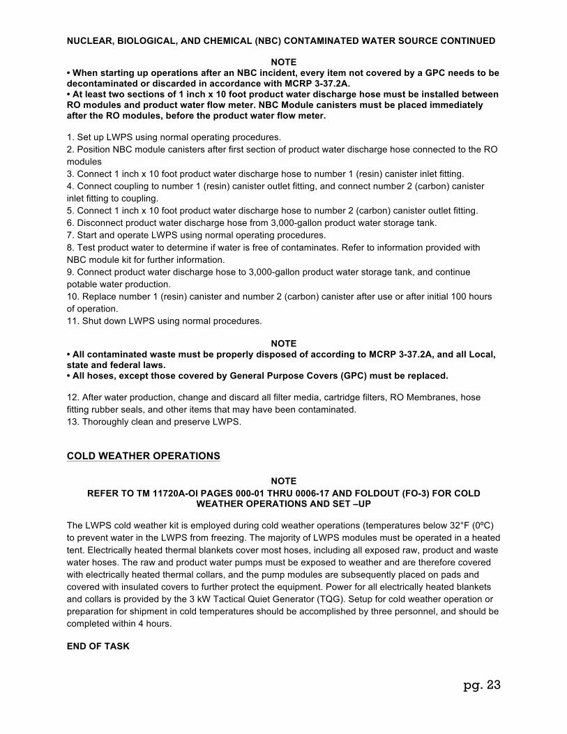
NUCLEAR, BIOLOGICAL, AND CHEMICAL (NBC) CONTAMINATED WATER SOURCE CONTINUED
NOTE
• When starting up operations after an NBC incident, every item not covered by a GPC needs to be decontaminated or discarded in accordance with MCRP 3-37.2A. • At least two sections of 1 inch x 10 foot product water discharge hose must be installed between RO modules and product water flow meter. NBC Module canisters must be placed immediately after the RO modules, before the product water flow meter. 1. Set up LWPS using normal operating procedures. 2. Position NBC module canisters after first section of product water discharge hose connected to the RO modules 3. Connect 1 inch x 10 foot product water discharge hose to number 1 (resin) canister inlet fitting. 4. Connect coupling to number 1 (resin) canister outlet fitting, and connect number 2 (carbon) canister inlet fitting to coupling. 5. Connect 1 inch x 10 foot product water discharge hose to number 2 (carbon) canister outlet fitting. 6. Disconnect product water discharge hose from 3,000-gallon product water storage tank. 7. Start and operate LWPS using normal operating procedures. 8. Test product water to determine if water is free of contaminates. Refer to information provided with NBC module kit for further information. 9. Connect product water discharge hose to 3,000-gallon product water storage tank, and continue potable water production. 10. Replace number 1 (resin) canister and number 2 (carbon) canister after use or after initial 100 hours of operation. 11. Shut down LWPS using normal procedures.
NOTE • All contaminated waste must be properly disposed of according to MCRP 3-37.2A, and all Local, state and federal laws. • All hoses, except those covered by General Purpose Covers (GPC) must be replaced. 12. After water production, change and discard all filter media, cartridge filters, RO Membranes, hose fitting rubber seals, and other items that may have been contaminated. 13. Thoroughly clean and preserve LWPS.
COLD WEATHER OPERATIONS
NOTE REFER TO TM 11720A-OI PAGES 000-01 THRU 0006-17 AND FOLDOUT (FO-3) FOR COLD
WEATHER OPERATIONS AND SET –UP
The LWPS cold weather kit is employed during cold weather operations (temperatures below 32°F (0ºC) to prevent water in the LWPS from freezing. The majority of LWPS modules must be operated in a heated tent. Electrically heated thermal blankets cover most hoses, including all exposed raw, product and waste water hoses. The raw and product water pumps must be exposed to weather and are therefore covered with electrically heated thermal collars, and the pump modules are subsequently placed on pads and covered with insulated covers to further protect the equipment. Power for all electrically heated blankets and collars is provided by the 3 kW Tactical Quiet Generator (TQG). Setup for cold weather operation or preparation for shipment in cold temperatures should be accomplished by three personnel, and should be completed within 4 hours. END OF TASK

pg. 24
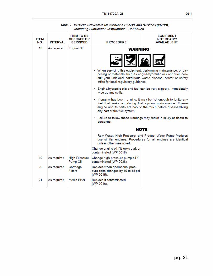
Periodic Preventive Maintenance Checks and Services (PMCS), Including Lubrication Instructions
Note For Operator/Field Maintenance Preventive Maintenance Checks and Services (PMCS), Including Lubrication Instructions Refer to TECHNICAL MANUAL 11720A-OI, Pages 0011-1 – Thru 0011-11

pg. 25

pg. 26

pg. 27

pg. 28
400

pg. 29

pg. 30
pg. 31

pg. 32

pg. 33
PREPARATION FOR STORAGE 0005 NOTE
Rinse components and modules with product water to remove sand, dirt, and debris if possible before preparing for storage.
1. Disconnect all hoses, flow meters, and modules. 2. Retrieve floating intake strainer or OISS strainers and associated components. 3. Drain all module components completely and close all drains. Drain all hoses completely. Dry all LWPS components completely. 4. Fold 1,000-gallon raw water tank and 3,000-gallon product water storage tank. Cover and secure tanks with ground covers for storage. 5. Pack all components into storage container boxes IAW packing list located in storage container box lids. 6. If available, install covers on all modules.
WARNING • Use extreme caution when lifting any component that is heavy. Provide adequate support and use assistance during procedure. Ensure that lifting equipment used is on solid footing, is in good condition, and is of suitable lift capacity. Keep clear of heavy parts supported only by lifting equipment. • Two personnel are required to safely move the LWPS modules. • To maintain even weight distribution, load QUADCON pallet and QUADCON as prescribed below. Uneven weight distribution could cause components to shift, resulting in an unstable load during transit. • Failure to follow these warnings may result in injury or death to personnel or damage to equipment.
NOTE
If forklift truck is not available to move QUADCON pallet, load modules onto pallet while pallet is inside QUADCON container.
7. Load LWPS components on QUADCON pallet as shown in Figures on next 2 pages

pg. 34

pg. 35
8. Load QUADCON pallet into QUADCON, as required. 9. Continue to load QUADCON IAW Figures on next 3 pages.

pg. 36
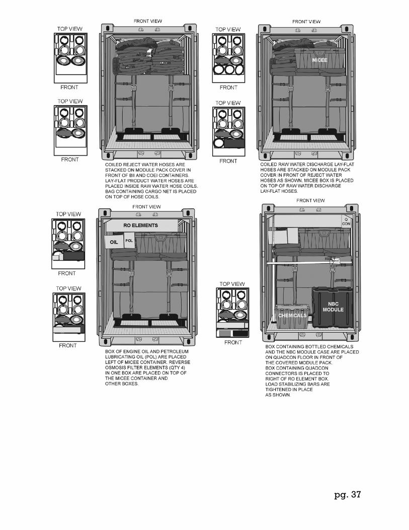
pg. 37

pg. 38
10. Secure and lock QUADCON doors.

pg. 39
Load LWPS components on HMMWV as shown below.
WARNING To maintain even weight distribution, load HMMWV or as prescribed below. Uneven weight
distribution could cause components to shift, resulting in an unstable load during transit. Failure to follow this warning may result in injury or death to personnel and damage to equipment.

pg. 40
Load LWPS components on LTT-H as shown
WARNING To maintain even weight distribution, load LTT-H as prescribed below. Uneven weight distribution could cause components to shift, resulting in an unstable load during transit. Failure to follow this
warning may result in injury or death to personnel and damage to equipment.
pg. 41