limbach l2400 only ef df et dt operatingandmaintenancemanual en
TRANSCRIPT
Ope ra ting and Main ten an ce Ma nu al
Lim bach L 2400EF/DFET/DT
En gi ne for Po we red Gli ders andVery Light Air craft
Edi ti on: 04.03.2001
Ap proval and trans la tion has been done by best knowl edge and judge ment. - In any case the orig i -nal text (P/N 250.253.500.000) in ger man lan guage is au thor i ta tive
Lim bach Flug mo to ren GmbH & Co. KGKot thaus ener Str.5D-53639 Kö nigs win ter, Ger ma nyTe le pho ne: (02244) 9201 - 0Te le fax: (02244) 9201 - 30
Ó Limbach Flugmotoren GmbH & Co. KG 250.253.501.000

Table of Contents
2. Change In dex 2-1
3. Engine Description 3-13.1. Model Designation 3-1
3.2. Cyl in der Des ig na tion 3-2
3.3. De scrip tion of Subsystems 3-3
3.3.1. Fuel Sys tem and In jec tion 3-3
3.3.2. Elec tri cal sys tem 3-3
3.3.3. Cooling 3-3
3.3.3.1. Liuid cool ing for the cyl in der heads 3-3
3.3.3.2. Oil cool ing: 3-3
3.3.3.3. Air cool ing of the cyl in ders: 3-4
3.3.4. Ig ni tion 3-4
3.3.5. Emer gency switch 3-4
3.3.6. Turbocharger 3-4
3.3.7. Inter cool er 3-4
4. Technical Data 4-14.1. LIMBACH L 2400 EF 4-1
4.1.1. Di men sions 4-1
4.1.2. Equip ment: 4-1
4.1.3. En gine Ratings 4-2
4.1.4. En gine Ro ta tional Speeds 4-2
4.1.5. Fuel and Oil: 4-2
4.1.6. Pres sures and Tem per a tures: 4-2
4.1.7. Liq uid quan ti ties: 4-3
4.2. LIMBACH L 2400 ET 4-4
4.2.1. Di men sions 4-4
4.2.2. Equip ment: 4-4
4.2.3. En gine Ratings 4-5
4.2.4. En gine Ro ta tional Speeds 4-5
4.2.5. Fuel and Oil: 4-5
4.2.6. Pres sures and Tem per a tures: 4-5
4.2.7. Liq uid quan ti ties: 4-6
5. Performance 5-75.1. Per for mance Graph LIMBACH L 2400 EF 5-7
5.1.1. Performance Data L 2400 EF 5-8
5.2. Per for mance Graph LIMBACH L 2400 ET 5-9
5.2.1. Performance Data L 2400 EF 5-10
6. Operating Instructions 6-16.1. Be fore Starting 6-1
6.2. En gine Start-Up 6-1
6.3. Runup, Per for mance Check 6-2
6.4. Hot En gine Start-Up 6-2
6.5. Take-Off 6-2
6.6. En gine Shut-Down 6-2
00
0.1
05.
35
2.0
52 :r
eb
mu
N tn
em
uco
DOperating Manual
L2400 EF/DF/ET/DT-Series1
Repl. edition from: 22.04.1999 Edition: 04.03.2000 Page: 1-2

6.7. Inflight Shut-Down and Re starting 6-2
6.8. Emer gency Pro ce dures 6-3
7. Maintenenance Schedule 7-17.1. Daily Check 7-1
7.2. Pe ri od i cal Checks 7-1
7.2.1. If the Engine is not Operated for more than 3 Months 7-1
7.2.2. Every 2 Years 7-1
7.2.3. Every 5 Years after New or Main Overhaul 7-1
7.3. Op er ating Time re lated In spec tions 7-2
7.3.1. After the first 5 Operating Hours 7-2
7.3.2. After the first 25 Operating Hours 7-2
7.3.3. Every 50 Operating Hours 7-2
7.3.4. Every 100 Operating Hours 7-3
7.3.5. Every 200 Operating Hours 7-3
7.3.6. Every 500 Operating Hours 7-3
8. Maintenence Instructions 8-18.1 Oil Change 8-1
8.2 Cleaning of Air Fil ter 8-1
8.3 Ad just Idling Speed 8-1
8.4 Fuel Fil ter Cleaning 8-2
8.5 Fuel, Lu bri ca tion and Cooling Sys tem Check 8-2
8.6 Crank case Ven ti la tion Check 8-2
8.7 Com pres sion Check 8-2
8.8 Check and Set ting of Valve Clear ance 8-2
8.9 Check of Valve Shaft Pro jecting Length 8-3
8.10 Cleaning, Check and Set ting of Spark Plugs 8-4
8.11 Drive Belt Check, Ten sioning and Re place ment 8-5
8.12 Ex haust Sys tem Check 8-5
8.13 Turbocharger Check 8-5
8.14 Bowden Ca ble Check 8-6
8.15 Emer gency Bat tery and Har ness Check 8-6
8.16 Check of Bolted Con nec tions 8-6
8.17 En gine Test Run 8-6
8.18 En gine Pres er va tion 8-6
8.19 Op er a tion at low am bi ent Tem per a tures 8-7
8.20 Op er a tion in Trop i cal Con di tions 8-8
8.21 Mis cel la neous 8-9
9. Overhaul 9-19.1. Ma jor Over haul 9-1
9.2. Ma jor Re pair 9-1
10. Lubricants and Coolants 10-110.1. List of Lu bri cants 10-1
10.2. Cool ant 10-2
11. Recommended Nut Torques 11-1
00
0.1
05.
35
2.0
52 :r
eb
mu
N tn
em
uco
DOperating Manual
L2400 EF/DF/ET/DT-Series1
Repl. edition from: 22.04.1999 Edition: 04.03.2000 Page: 1-3

12. Trouble Shooting 12-112.1. En gine Starting Trou ble 12-1
12.2. En gine Op er ating Trou ble 12-2
12.2.1. Fuel Supply 12-2
12.2.2. Ignition 12-3
12.2.3. Cooling 12-3
12.2.4. Lubrication 12-4
12.3. Ex haust / Turbocharger Sys tem 12-4
12.3.1. Mechanical System 12-5
12.4. En gine Op er ating Trou ble in Nor mal Mode, no Trou ble in Emer gency Mode 12-5
00
0.1
05.
35
2.0
52 :r
eb
mu
N tn
em
uco
DOperating Manual
L2400 EF/DF/ET/DT-Series1
Repl. edition from: 22.04.1999 Edition: 04.03.2000 Page: 1-4
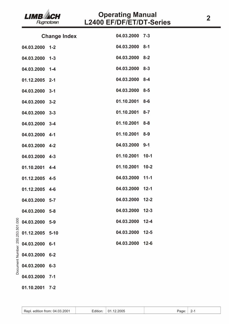
Change Index
04.03.2000 1-2
04.03.2000 1-3
04.03.2000 1-4
01.12.2005 2-1
04.03.2000 3-1
04.03.2000 3-2
04.03.2000 3-3
04.03.2000 3-4
04.03.2000 4-1
04.03.2000 4-2
04.03.2000 4-3
01.10.2001 4-4
01.12.2005 4-5
01.12.2005 4-6
04.03.2000 5-7
04.03.2000 5-8
04.03.2000 5-9
01.12.2005 5-10
04.03.2000 6-1
04.03.2000 6-2
04.03.2000 6-3
04.03.2000 7-1
01.10.2001 7-2
04.03.2000 7-3
04.03.2000 8-1
04.03.2000 8-2
04.03.2000 8-3
04.03.2000 8-4
04.03.2000 8-5
01.10.2001 8-6
01.10.2001 8-7
01.10.2001 8-8
01.10.2001 8-9
04.03.2000 9-1
01.10.2001 10-1
01.10.2001 10-2
04.03.2000 11-1
04.03.2000 12-1
04.03.2000 12-2
04.03.2000 12-3
04.03.2000 12-4
04.03.2000 12-5
04.03.2000 12-6
00
0.1
05.
35
2.0
52 :r
eb
mu
N tn
em
uco
DOperating Manual
L2400 EF/DF/ET/DT-Series2
Repl. edition from: 04.03.2001 Edition: 01.12.2005 Page: 2-1
3. Engine Description
• Hor i zon tally Op posed 4-Cylinder 4-Stroke Re cip ro cating En gine
• Com bined Liq uid Cooling for the Cyl in der Heads
• Ram Air Cooling for the Cyl in ders
• Wet Sump Forced Lu bri ca tion
• Sin gle Elec tronic En gine Man age ment Sys tem Pro viding Spark and Fuel
• Di rect Pro pel ler Drive
• Elec tri cal Starter
• Al ter na tor
3.1. Model Designation
L 2400 E F 1 . X X
1. 2. 3. 4. 5. 6. 7.
1. LIMBACH (Man u fac turer)
2. Dis place ment Class in cm3
3. (E) Sin gle Ig ni tion (D) Dual Ig ni tion
4. Equip ment - Ba sic Type of Con struc tion
F = Trac tor Pro pel lerElec tronic en gine man age mentLiq uid cool ing for cyl in der headsRam air cool ing for cyl in dersGen er a tor rearStarter rear
T = Trac tor Pro pel lerTurbocharger, IntercoolerElec tronic en gine man age mentLiq uid cool ing for cyl in der headsRam air cool ing for cyl in dersGen er a tor rearStarter rear
5. Type of Pro pel ler Flange
1 = Flange for Vari able-Pitch Pro pel ler2 = Flange for Fixed-Pitch Pro pel ler3 = Flange for Fixed-Pitch Pro pel ler (SAE 1)
6 + 7. In stal la tionType Dif fer ences with re gard to in stal la tion re lated changes
X = Ex per i men tal En gine with out Cer tif i ca tion
00
0.1
05.
35
2.0
52 :r
eb
mu
N tn
em
uco
DOperating Manual
L2400 EF/DF/ET/DT-Series3
Repl. edition from: 22.04.1999 Edition: 04.03.2000 Page: 3-1

3.2. Cyl in der Des ig na tion
Front = Pro pel ler Side
Rear = Ac ces sory Mount ing Side
00
0.1
05.
35
2.0
52 :r
eb
mu
N tn
em
uco
DOperating Manual
L2400 EF/DF/ET/DT-Series3
Repl. edition from: 22.04.1999 Edition: 04.03.2000 Page: 3-2
1
3
2
4
front
rear
top
bottom
rotation
right left
3.3. De scrip tion of Subsystems
3.3.1. Fuel Sys tem and In jec tion
The fuel is sup plied to the in jec tors via a ring-type fuel line. That pre vents for ma tion of va -por locks. The tank acts as a ra di a tor. The fuel flows from the tanks via the fuel shut-offvalve to the ac tive pump, from the pump to the fil ter/drainer, to the in jec tors no. 4 and 2 andthen to in jec tors 1 and 3. From the in jec tors the fuel flows via the fuel pres sure sen sor to the fuel pres sure reg u la tor. The un used fuel is then re turned to the tanks.
3.3.2. Elec tri cal sys tem
The re lay box (MCU) sup plies the en gine with elec tri cal cur rent from the gen er a tor, the bat -tery and the emer gency bat tery. The nom i nal volt age is 12 V. Since the en gine re lies on afunc tional power sup ply, the re lay box and an emer gency bat tery are nec es sary. No elec tri cal cur rent may flow from the emer gency bat tery into the elec tri cal sys tem of the air frame. Stillthe emer gency bat tery is con stantly charged.
The fol low ing fail ure modes re gard ing the elec tri cal sys tem must be con sid ered:
1. On fail ure of the main bat tery (de fect, does not charge any more), the emer gency bat tery re -places the main bat tery. The en gine may be op er ated with out re stric tions. The en gine maynot be re started with the elec tric starter. The amperemeter be tween bat tery and elec tri calsys tem does not show any charge.
2. On fail ure of the gen er a tor (gen er a tor warn ing lamp lights up) the en gine will con tinue torun un til both bat ter ies are de pleted.
First the main bat tery is drained, air frame sys tems such as the ra dio may be op er ated. As themain bat tery’s volt age de creases, the emer gency bat tery takes over. Now the red warn inglamp “Emer gency Bat tery Dis charging” blinks. Ra dio and other air frame sys tems are nowin ac tive.
3. If the air frame elec tri cal sys tem does not work any more, the emer gency bat tery will sup plythe en gine with elec tri cal cur rent for a lim ited time.
In flight a de fec tive emer gency bat tery can not be de tected.
3.3.3. Cooling
The cool ing sys tem of the L 2400 EF con sists of the fol low ing sub sys tems:
• Liq uid cool ing cir cuit for the cyl in der heads
• Oil cool ing
• Air cool ing for the cyl in ders
3.3.3.1. Liuid cool ing for the cyl in der heads
This sys tem con sists of a cool ant pump, cool ant tubes and hoses, liq uid cooled cyl in derheads, an ex pan sion ves sel with overpressure and vacum valves, a ra di a tor and the cool ant.
3.3.3.2. Oil cool ing:
The sys tem con sists of a ther mo stat adapter at tached to the crank case, oil hoses and an oilcooler.
00
0.1
05.
35
2.0
52 :r
eb
mu
N tn
em
uco
DOperating Manual
L2400 EF/DF/ET/DT-Series3
Repl. edition from: 22.04.1999 Edition: 04.03.2000 Page: 3-3

3.3.3.3. Air cool ing of the cyl in ders:
The air is duct ed over the cyl in ders via two open ings in the cowl ing
3.3.4. Ig ni tion
The ig ni tion sys tem is a solid state sys tem with vari able ig ni tion tim ing. The tim ing is con -trolled through a map in the ECU (En gine Con trol Unit). The ig ni tion sys tem con sists oftwo ig ni tion mod ules and two dual spark ig ni tion coils.
3.3.5. Emer gency switch
The emer gency switch is used in case of a fail ure in the fuel pump or of a sen sor. In emer -gency mode a sec ond pump re places the pre vi ously ac tive pump, the sec ond rpm-sensor re -places the pre vi ously ac tive sen sor and the other sen sors are re placed by fixed valuere sis tors. The en gine may also be started in emer gency mode as long as the main switch is in the “ON” po si tion and the main bat tery is func tional.
3.3.6. Turbocharger
L 2400 ET/DT mod els fea ture a sin gle stage turbocharger. The turbocharger fea tures a boost pres sure lim iter that dis charges ex haust gas into the ex haust when the max i mum pres sure isreached. A stain less steel ex haust sys tem is used to col lect the ex haust gases and feeds themto the ex haust tur bine. The ex haust sys tem is in su lated to in crease the turbochargers ef fi -ciency and to re duce the tem per a tures in the en gine com part ment. The turbocharger ismounted high in the rear of the en gine. Ist lu bri cat ing oil drains into the oil sump by grav ity. The tur bine shaft is liq uid cooled via the en gine cool ing sys tem.
3.3.7. Inter cool er
An air to air inter cool er low ers the charge air tem per a ture to im prove ef fi ciency and to lower the ther mal load ing of the en gine. The cool ing air is sup plied via a duct in the en gine cowl -ing.
00
0.1
05.
35
2.0
52 :r
eb
mu
N tn
em
uco
DOperating Manual
L2400 EF/DF/ET/DT-Series3
Repl. edition from: 22.04.1999 Edition: 04.03.2000 Page: 3-4
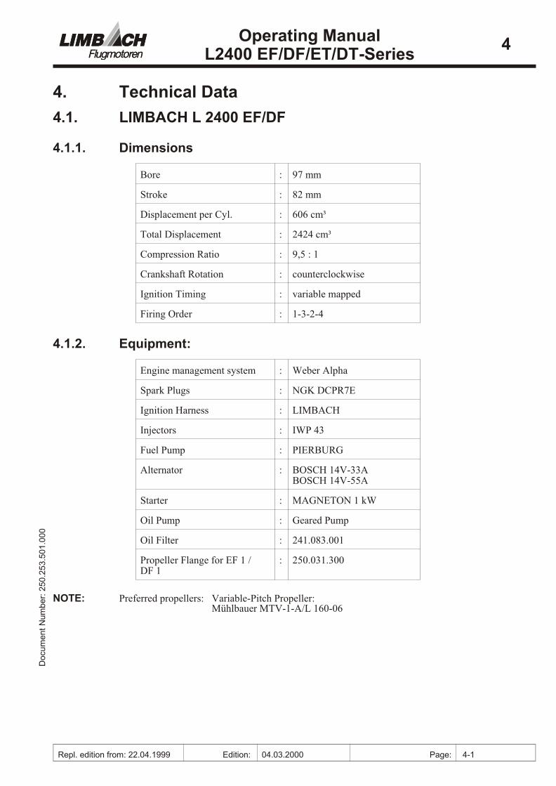
4. Technical Data
4.1. LIMBACH L 2400 EF/DF
4.1.1. Di men sions
Bore : 97 mm
Stroke : 82 mm
Dis place ment per Cyl. : 606 cm³
To tal Dis place ment : 2424 cm³
Com pres sion Ra tio : 9,5 : 1
Crank shaft Ro ta tion : coun ter clock wise
Ig ni tion Tim ing : vari able mapped
Firing Or der : 1-3-2-4
4.1.2. Equip ment:
En gine man age ment sys tem : Weber Al pha
Spark Plugs : NGK DCPR7E
Ig ni tion Har ness : LIMBACH
In jec tors : IWP 43
Fuel Pump : PIERBURG
Al ter na tor : BOSCH 14V-33ABOSCH 14V-55A
Starter : MAG NETON 1 kW
Oil Pump : Geared Pump
Oil Fil ter : 241.083.001
Pro pel ler Flange for EF 1 /DF 1
: 250.031.300
NOTE: Pre ferred pro pel lers: Vari able-Pitch Pro pel ler:Mühlbauer MTV-1-A/L 160-06
00
0.1
05.
35
2.0
52 :r
eb
mu
N tn
em
uco
DOperating Manual
L2400 EF/DF/ET/DT-Series4
Repl. edition from: 22.04.1999 Edition: 04.03.2000 Page: 4-1

4.1.3. En gine Ratings
Max. Take-Off Power : 74 kW / 100 shp @ 3000RPM 30 in. Hg
Max. Con tin u ous Power : 62 kW / 84,5 shp @ 3000RPM 28 in. Hg
4.1.4. En gine Ro ta tional Speeds
Max. per mis si ble speed : 3200 RPM
Max. speed for cruise : 1
Min. con tin u ous speed : 2300 RPM
Idle speed : 800±100 RPM
4.1.5. Fuel and Oil:
Fuel : AV GAS 100 LL orSuper-Plus un leaded ac cord -ing to DIN EN 228 min. 98oc tane (RON)
En gine Oil : see sec tion 10
Cool ant : see sec tion 10
4.1.6. Pres sures and Tem per a tures:
Fuel Pres sure : 2.5 bar / 14.6 psi 2
En gine Oil Pres sure max.min.
: 7 bar / 101.5 psi 1 bar / 14.5 psi @ 2500 RPM
En gine Oil Tem per a ture max min. opt.
: 120 °C 3
50 °C (in di cated)appr. 80 °C
Wa ter Tem per a ture max. opt.
: 110 °C70 to 90 °C (at cruise)4
00
0.1
05.
35
2.0
52 :r
eb
mu
N tn
em
uco
DOperating Manual
L2400 EF/DF/ET/DT-Series4
Repl. edition from: 22.04.1999 Edition: 04.03.2000 Page: 4-2
1 See flight and maintainance manual of airframe manufacturer.
2 Measured relative to the manifold pressure
3 The max. per mis si ble tem per a tures con sti tute op er at ing lim i ta tions to be main tained for a shortpe riod of time only. Con tin u ous op er a tion of the en gine at these tem per a tures may im pair en ginelife.
4 See note 3

4.1.7. Liq uid quan ti ties:
En gine Oil Charge max.
min.
: 3.5 Ltr. 2.75 Ltr.
Cool ant : ca. 3.5 Ltr.
00
0.1
05.
35
2.0
52 :r
eb
mu
N tn
em
uco
DOperating Manual
L2400 EF/DF/ET/DT-Series4
Repl. edition from: 22.04.1999 Edition: 04.03.2000 Page: 4-3

4.2. LIMBACH L 2400 ET/DT
4.2.1. Di men sions
Bore : 97 mm
Stroke : 82 mm
Dis place ment per Cyl. : 606 cm³
To tal Dis place ment : 2424 cm³
Com pres sion Ra tio : 8,0 : 1
Crank shaft Ro ta tion : coun ter clock wise
Ig ni tion Tim ing : vari able mapped
Firing Or der : 1-3-2-4
4.2.2. Equip ment:
En gine man age ment sys tem : Weber Al pha
Spark Plugs : NGK DCPR7E
Ig ni tion Har ness : LIMBACH
In jec tors : IWP 43
Fuel Pump : PIERBURG
Al ter na tor : BOSCH 14V-33ABOSCH 14V-55A
Starter : MAG NETON 1 kW
Oil Pump : Geared Pump
Oil Fil ter : 241.083.001
Turbocharger : 250.173.100
Pro pel ler Flange forET 1/DT 1
: 250.031.300
NOTE: Pre ferred pro pel lers: Vari able-Pitch Pro pel ler:Mühlbauer MTV-1-A
00
0.1
05.
35
2.0
52 :r
eb
mu
N tn
em
uco
DOperating Manual
L2400 EF/DF/ET/DT-Series4
Repl. edition from: 04.03.2001 Edition: 01.10.2001 Page: 4-4

4.2.3. En gine Rat ing
Max. Take-Off Power : 96 kW / 130 shp @ 3000 RPM 40 in. Hg5
41 in. Hg6
Max. Con tin u ous Power : 85 kW / 115 shp @ 3000 RPM 38 in. Hg 7
39 in. Hg8
4.2.4. En gine Ro ta tional Speeds
Max. per mis si ble speed : 3200 RPM
Max. speed for cruise : 9
Min. con tin u ous speed : 2400 RPM
Idle speed : 800±100 RPM
4.2.5. Fuel and Oil:
Fuel : AV GAS 100 LL orSuper-Plus un leaded ac cord -ing to DIN EN 228 min. 98oc tane (RON)
En gine Oil : see sec tion 10
Cool ant : see sec tion 10
4.2.6. Pres sures and Tem per a tures:
Fuel Pres sure : 2.5 bar / 14.6 psi10
En gine Oil Pres sure max.min.
: 7 bar / 101.5 psi 1 bar / 14.5 psi @ 2500 RPM
00
0.1
05.
35
2.0
52 :r
eb
mu
N tn
em
uco
DOperating Manual
L2400 EF/DF/ET/DT-Series4
Repl. edition from: 04.03.2001 Edition: 01.12.2005 Page: 4-5
5 Applies to turbocharger 250.173.100
6 Applies to turbocharger 250.173.101
7 Applies to turbocharger 250.173.100
8 Applies to turbocharger 250.173.101
9 See flight and maintainance manual of airframe manufacturer.
10 Measured relative to the manifold pressure

En gine Oil Tem per a ture max min. opt.
: 120 °C 11
50 °C (in di cated)appr. 80 °C
Wa ter Tem per a ture max. opt.
: 110 °C70 to 90 °C (at cruise)12
4.2.7. Liq uid quan ti ties:
En gine Oil Charge max.
min.
: 3.5 Ltr. 2.75 Ltr.
Cool ant : ca. 3.5 Ltr.
00
0.1
05.
35
2.0
52 :r
eb
mu
N tn
em
uco
DOperating Manual
L2400 EF/DF/ET/DT-Series4
Repl. edition from: 04.03.2001 Edition: 01.12.2005 Page: 4-6
11 The max. per mis si ble tem per a tures con sti tute op er at ing lim i ta tions to be main tained for a shortpe riod of time only. Con tin u ous op er a tion of the en gine at these tem per a tures may im pair en ginelife.
12 See note 2

5. Performance
5.1. Per for mance Graph LIMBACH L 2400 EF/DF
00
0.1
05.
35
2.0
52 :r
eb
mu
N tn
em
uco
DOperating Manual
L2400 EF/DF/ET/DT-Series5
Repl. edition from: 22.04.1999 Edition: 04.03.2000 Page: 5-7
20
30
40
50
60
70
80
2000 2200 2400 2600 2800 3000
RPM [1/min]
Po
wer
[kW
]
150
200
250
300
To
rqu
e[N
m];
SF
C[g
/kW
h]
Power
Torque
SFC

5.1.1. Performance Data L 2400 EF/DF
Power val ues in HP
Man i foldpres sureinHg
2400 rpm 2500 rpm 2600 rpm 2700 rpm 2800 rpm 2900 rpm 3000 rpm
20 38
21 45
22 46 51
23 52 57
24 58 63
25 60 65 75
26 66 72
27 74 79
28 82 85
29 91
30 76 81 87 92 95 98 100
00
0.1
05.
35
2.0
52 :r
eb
mu
N tn
em
uco
DOperating Manual
L2400 EF/DF/ET/DT-Series5
Repl. edition from: 22.04.1999 Edition: 04.03.2000 Page: 5-8
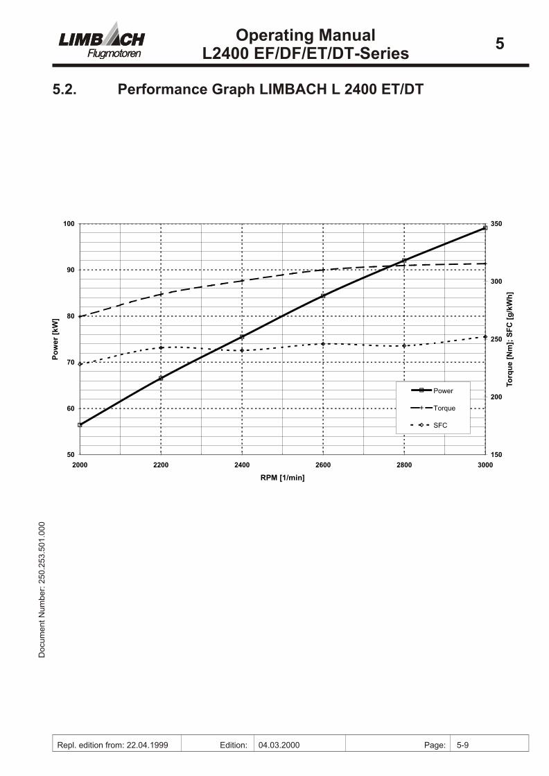
5.2. Per for mance Graph LIMBACH L 2400 ET/DT
00
0.1
05.
35
2.0
52 :r
eb
mu
N tn
em
uco
DOperating Manual
L2400 EF/DF/ET/DT-Series5
Repl. edition from: 22.04.1999 Edition: 04.03.2000 Page: 5-9
50
60
70
80
90
100
2000 2200 2400 2600 2800 3000
RPM [1/min]
Po
wer
[kW
]
150
200
250
300
350
To
rqu
e[N
m];
SF
C[g
/kW
h]
Power
Torque
SFC

5.2.1. Performance Data L 2400 ET/DT
Power val ues in kW resp HP in parethesis ()
Man i fold Pressure inHg 2200rpm 2400 rpm 2600 rpm 2800 rpm 3000 rpm
1 2
23 24 29 (40/) 34,5 (47) 37 (50) 40 (54) 42 (57)
24 25 31,5 (43) 37 (50) 39 (53) 42 (57) 44 (60)
25 26 34 (46) 38 (52) 40,5 (55) 44 (60) 46 (63)
26 27 36 (49) 40 (54) 42 (57) 46 (63) 48,5 (66)
27 28 38 (52) 42 (57) 43,5 (59) 49 (67) 51,5 (70)
28 29 40,5 (55) 44 (60) 45,5 (62) 51,5 (70) 54,5 (74)
29 30 42 (57) 45,5 (62) 49 (67) 53,5 (73) 57,5 (78)
30 31 44 (60) 48 (65) 53 (72) 57 (77) 61 (83)
31 32 45,5 (62) 50 (68) 57 (77) 60 (81) 64 (87)
32 33 48,5 (66) 52 (71) 60 (82) 63 (86) 67 (91)
33 34 51 (69) 55 (75) 62 (84) 67 (91) 51 (96)
34 35 53 (72) 57,5 (78) 63 (87) 69 (94) 73,5 (100)
35 36 55 (75) 60 (81) 66 (90) 71,5 (97) 76 (103)
36 37 57,5 (78) 62,5 (85) 68,5 (93) 74 (101) 79,5 (108)
37 38 60 (82) 65,5 (89) 71 (97) 78 (106) 82,5 (112)
38 39 62,5 (85) 69 (94) 75 (102) 82 (111) 86 (117)
39 40 73 (99) 79 (107) 85 (116) 90 (122)
40 41 84 (114) 90,5 (123) 96 (131)
00
0.1
05.
35
2.0
52 :r
eb
mu
N tn
em
uco
DOperating Manual
L2400 EF/DF/ET/DT-Series5
Repl. edition from: 04.03.2001 Edition: 01.12.2005 Page: 5-10
1 Applies to turbocharger 250.173.100.000
2 Applies to turbocharger 250.173.101.000

6. Operating InstructionsStrict ad her ence to the in for ma tion con tained in this op er at ing man ual is the ba sis for un dis -turbed op er a tion of your en gine.
6.1. Be fore Starting
Per form daily check (see sec tion 7.1.) * Move power le ver to throt tle full open po si tion.Check for in ter fer ence and free move ment be tween the idle cut off and full open stops at thethrot tle body. * Turn pro pel ler man u ally sev eral times with ig ni tion switched off. Check forab nor mal sound, rough move ment and equal compresion forces of the en gine.
CAU TION: When turn ing the en gine, be aware that en gine start ing is pos si ble at any time!
6.2. En gine Start-Up
Open fuel shut off valve.
Turn mas ter switch and en gine elec tri cal sys tem on.
Fuel pump starts and turns it self off af ter ap prox i mately 10 sec onds.
Turn ig ni tion off.
Turn emer gency switch to emer gency mode.
Turn ig ni tion on.
Yel low in di cat ing light is on. Fuel pump starts and turns it self off af ter ap prox i mately 10sec onds.
Turn emer gency switch to nor mal mode.
Yel low in di cat ing light is off
Set throt tle slightly above idle.
Check pro pel ler clear ance.
Start en gine.
When the en gine is fir ing, re lease starter but ton and set en gine speed to appr. 1300 RPMby means of the throt tle le ver.
Check oil pres sure (must in crease within 10 sec.).
00
0.1
05.
35
2.0
52 :r
eb
mu
N tn
em
uco
DOperating Manual
L2400 EF/DF/ET/DT-Series6
Repl. edition from: 22.04.1999 Edition: 04.03.2000 Page: 6-1

6.3. Runup, Per for mance Check
Run the en gine for approx. 2 min. at 1300 RPM. Then in crease speed to 1500 RPM un til oiltem per a ture is 50 °C.
Due to the slug gish ac tion of the in di ca tion, there will be suf fi cient ef fec tive op er at ingtem per a ture at 50 °C al ready.
6.3.1. Per for mance Check
Move throt tle le ver to full-throttle stop. En gine has to reach the full-throttle static speedpub lished in the flight and main te nance man ual of the air craft man u fac turer. Re turn throt -tle le ver to idle.
6.3.2. Ig ni tion Check
Ac cel er ate the en gine to 2000 RPM with the throt tle le ver. Turn the ig ni tion switch fromthe mode “Both” to each of the sin gle modes “1” and “2”. The max i mum rpm drop shallnot be more than 100 rpm. Turn the ig ni tion switch back to “Both”
CAU TION: If full-throttle ground runs are made for a lon ger pe riod, over heat ing of the en gine ispos si ble!
6.4. Hot En gine Start-Up
Hot en gine start ing is per formed as de scribed in Chap ter 5.2, but with out check ing the emer -gency switch
6.5. Take-Off
In crease en gine speed steadily to full throt tle and per form first part of climb with this set ting, then re duce power.
Check oil tem per a ture and oil pres sure. The limit val ues must not be ex ceeded.
CAU TION: With in creas ing am bi ent tem per a tures the en gine power and the lift up of the wingswill be re duced. This ap plies es pe cially to sit u a tions in which the run way has beenheated up by sun light.
6.6. En gine Shut-Down
Shut en gine down by switch ing ig ni tion off.
CAU TION: Af ter taxi ing for an ex tended pe riod or at high power, run the en gine at approx.1300 RPM for 2 to 3 min. Close fuel shut off valve.
6.7. Inflight Shut-Down and Re starting
Set throt tle to idle, let en gine cool down and switch off ig ni tion. To avoid wind mill ing bring pro pel ler into feath ered po si tion. On air craft with fixed pitch pro pel ler ac ti vate pro pel lerbrake or re duce speed. Starting en gine is the same as on the ground. If the en gine is cold,perfom warm-up.
At low am bi ent tem per a tures and af ter pro longed soarings:
00
0.1
05.
35
2.0
52 :r
eb
mu
N tn
em
uco
DOperating Manual
L2400 EF/DF/ET/DT-Series6
Repl. edition from: 22.04.1999 Edition: 04.03.2000 Page: 6-2

• the en gine oil may have cooled so much, that the en gine can not be started any more,
• the ca pac ity of the start ing bat tery may be re duced (see sec tion 8.19)
6.8. Emer gency Pro ce dures
If en gine op er a tion is dis turbed, the emer -gency switch (S) (Fig.:6-1) should beturned into emer gency mode (30 deg.Clock wise) In that case fol low ing ac tionsare taken:
• The sen sors for en gine opertion areswitched off resp changed.
• A re serve fuel pump is taken into op er a -tion.
• A yel low warn ing light (E) co mes on(lamp is on continouosly as long as theswitch is in the emer gency po si tion.)
Dur ing emer gency op er a tion the ex haustgas tem per a ture (EGT) must be mon i tored.Ad just the power le ver such that the ex -haust gas tem per a ture is in a range be tween 600 and 750 °C, de pend ing on rpm. If theex haust gas temperture ex ceeds the limit,the power must be re duced un til the tem -per a ture co mes be tween lim its again. Atlow power set tings the ex haust gas tem per -a tures may be lower than stated. In suchcases the power le ver should be ad justedsuch that the en gine runs as smooth as pos -si ble. The en gine may be re started in emer -gency mode as long as the main bat tery isfunc tional and the mas ter switch is in the“ON” po si tion.
If the red warn ing light on the sta tusinicator (Fig.: 6-2) “ Dis charge” [C] co meson, con sider the fol low ing:
• The elec tri cal sys tem is dis turbed.
• The op er at ing time for the en gine is lim -ited. (Check the flight man ual for the time reaining to fly)
• Take course to the next pos si ble land ing site. Ad just your flight at ti tude to a max i mumrange (climb at el e vated speed), check the flight man ual.
• The en gine may not be re started with the elec tric starter (Starting only pos si ble by wind -mill ing and con sid er able loss of al ti tude).
CAU TION: If the lamp “Emer gency Bat tery Dis charge” co mes on, the time avail able to op er ate the en gine is lim ited.
00
0.1
05.
35
2.0
52 :r
eb
mu
N tn
em
uco
DOperating Manual
L2400 EF/DF/ET/DT-Series6
Repl. edition from: 22.04.1999 Edition: 04.03.2000 Page: 6-3
Engine EmergencySwitch
Normal Emergency
E
SFig. 6-1 Emergency Switch
Treibstoffdruck
NotbatterieEntladen Laden
Betriebssd.
0123,45
D CP
HFig. 6-2 Status Indicator

7. Maintenenance ScheduleMain te nance at Limbach air craft en gines is to be per formed af ter fixed time pe ri ods or whenreach ing a cer tain in ter val of op er at ing hours. In ad di tion, a “daily check” has to be per -formed be fore each flight.
Ex haust muf fler1 and fuel fil ters system are not part of the en gine man u fac turer’s scope ofde liv ery. In spec tions and main te nance have to be per formed ac cord ing to the air craft man u -fac turer’s spec i fi ca tions.
7.1. Daily Check
• Re move en gine cowl ing.
• Check bolted con nec tions for ob vi ously loose or miss ing fasteners.
• Check baf fle as sem bly.
• Check ra di a tor, oil cooler and inter cool er2 for ob struc tion3
• Check har ness.
• Check con di tion of drive belt.
• Check cowl ing for cracks and cor rect at tach ment.
• Check clear ance of throt tle pushrods and bowden ca bles.
• Check en gine oil level and re fill as nec es sary. Vol ume dif fer ence be tween max. and min.mark ings: 0.75 Ltr.
• Check cool ant level and re fill as nec es sary4.
• Check oil, fuel and cooling sys tem for leak age.
• Check acid level of bat ter ies and re fill as nec es sary.
• Per form test run (see Chap ter 7.20).
7.2. Pe ri od i cal Checks
7.2.1. If the Engine is not Operated for more than 3 Months
Check ca pac ity of emer gency bat tery with a bat tery tester
7.2.2. Every 2 Years
Re place ment of emer gency bat tery rec om mended (de pend ing on bat tery type)
7.2.3. Every 5 Years after New or Main Overhaul
Re place oil and fuel hoses (mounted to the en gine). The oil and fuel hoses mounted to theen gine are signed with an ex pi ra tion date, e.g. 5.01 - i.e. to be re placed not later than May2001.
00
0.1
05.
35
2.0
52 :r
eb
mu
N tn
em
uco
DOperating Manual
L2400 EF/DF/ET/DT-Series7
Repl. edition from: 22.04.1999 Edition: 04.03.2000 Page: 7-1
1 On turbocharged engines ET/DT models the exhaust collector (pipes running from the engine to theturbocharger) are part of the engine.
2 L 2400 ET/DT only
3 Clean radiator and/or oil cooler if necessary.
4 After refilling the glycol content may have to be reestablished.
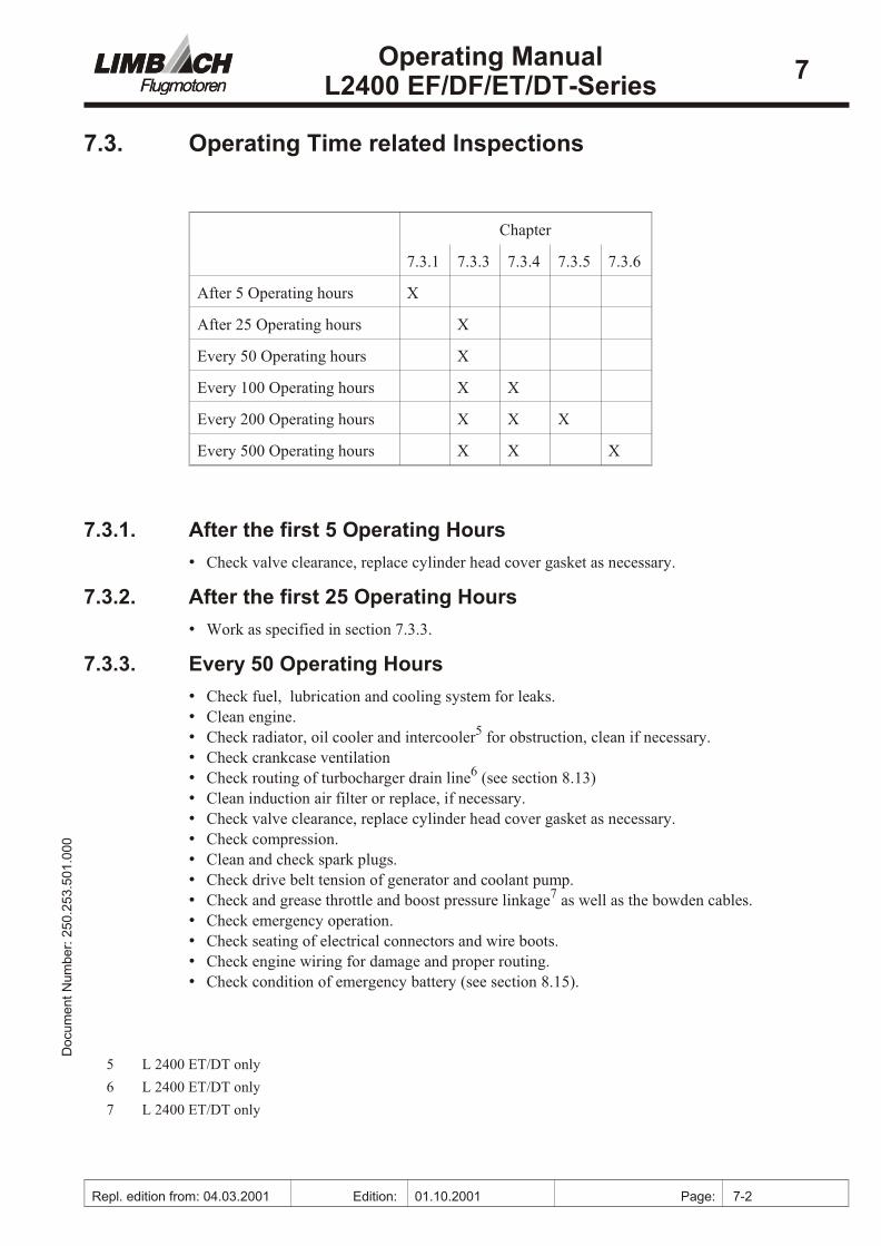
7.3. Op er ating Time re lated In spec tions
Chap ter
7.3.1 7.3.3 7.3.4 7.3.5 7.3.6
Af ter 5 Op er ating hours X
Af ter 25 Op er ating hours X
Ev ery 50 Op er ating hours X
Ev ery 100 Op er ating hours X X
Ev ery 200 Op er ating hours X X X
Ev ery 500 Op er ating hours X X X
7.3.1. After the first 5 Operating Hours
• Check valve clear ance, re place cyl in der head cover gas ket as nec es sary.
7.3.2. After the first 25 Operating Hours
• Work as spec i fied in sec tion 7.3.3.
7.3.3. Every 50 Operating Hours
• Check fuel, lu bri ca tion and cooling sys tem for leaks.
• Clean en gine.
• Check ra di a tor, oil cooler and inter cool er5 for ob struc tion, clean if nec es sary.
• Check crank case ven ti la tion
• Check rout ing of turbocharger drain line6 (see sec tion 8.13)
• Clean in duc tion air fil ter or re place, if nec es sary.
• Check valve clear ance, re place cyl in der head cover gas ket as nec es sary.
• Check com pres sion.
• Clean and check spark plugs.
• Check drive belt ten sion of gen er a tor and cool ant pump.
• Check and grease throt tle and boost pres sure link age7 as well as the bowden ca bles.
• Check emer gency op er a tion.
• Check seat ing of elec tri cal con nec tors and wire boots.
• Check en gine wir ing for dam age and proper rout ing.
• Check con di tion of emer gency bat tery (see sec tion 8.15).
00
0.1
05.
35
2.0
52 :r
eb
mu
N tn
em
uco
DOperating Manual
L2400 EF/DF/ET/DT-Series7
Repl. edition from: 04.03.2001 Edition: 01.10.2001 Page: 7-2
5 L 2400 ET/DT only
6 L 2400 ET/DT only
7 L 2400 ET/DT only

• Check bolts, nuts, safety pins, and en gine mount ing frame for tight fit and proper con di -tion.
• Per form en gine test run.
7.3.4. Every 100 Operating Hours
• Change oil and re place oil fil ter.
• Change fuel fil ter .
• Work as spec i fied in sec tion 7.3.3.
7.3.5. Every 200 Operating Hours
• Re place spark plugs
• Work as spec i fied in sec tion 7.3.3.
• Work as spec i fied in sec tion 7.3.4.
7.3.6. Every 500 Operating Hours
• Check valve shaft pro ject ing length.
• Work as spec i fied in sec tion 7.3.3.
• Work as spec i fied in sec tion 7.3.4.
00
0.1
05.
35
2.0
52 :r
eb
mu
N tn
em
uco
DOperating Manual
L2400 EF/DF/ET/DT-Series7
Repl. edition from: 22.04.1999 Edition: 04.03.2000 Page: 7-3

8. Maintenence InstructionsThis chap ter de scribes the per for mance of main te nance work. In ad di tion, the pres er va tion of en gines as well as win ter and trop i cal op er a tion is cov ered.
CAU TION: Re move ig ni tion har ness from the spark plugs be fore start ing any work on the en gine.
NOTE: Vac uum pump equipped air craft en gines must never be turned op po site to the en gine ro ta -tion be cause the vac uum pump might be dam aged. Check with your air wor thi ness in spec torif in spec tion is man da tory be fore start ing work.
It is rec om mended to mark the po si tion of parts to be re moved be fore com menc ing dis as -sem bly work in or der to fa cil i tate as sem bly later on. This is only ap pli ca ble to parts whichmight be in stalled in dif fer ent po si tions. Dur ing as sem bly, pay at ten tion to mark ings pro -vided by the man u fac turer.
The ig ni tion har ness is marked by the man u fac turer. The spark plug con nec tors are markedwith the cyl in der num bers. It is not im por tant whether they are at tached to the out- or in -board spark plugs.
8.1 Oil Change
Warm up en gine.
Drain oil.
Re move drain plug. Af ter all oil is drained, in stall drain plug with a new gas ket.
Change oil fil ter.
Re move oil fil ter. Slightly oil the rub ber seal of the new fil ter be fore mount ing andtighten fil ter man u ally.
Re fill en gine oil.
The oil charge is 3.5 l. Check oil level by means of the oil-measuring stick. The MAXmark ing must not be ex ceeded. The en gine must be hor i zon tally ori en tated. This is es pe -cially im por tant for so called “taildragger” Air craft.
Run up en gine and re check oil level. Add oil if nec es sary.
See sec tion 10.1. for oil spec i fi ca tions.
8.2 Cleaning of Air Fil ter
Re move air fil ter.
Clean air fil ter, us ing com pressed air, blow ing from in side outwards.
Spe cial fil ters are to be cleaned ac cord ing to the air craft man u fac turer’s in struc tions.
8.3 Ad just Idling Speed
The idling speed may be ad justed via the ad just ing screw on the throt tle body. The speedshould be ad justed to 800 ± 100 rpm. Turn ing the screw clock wise in creases idling speed.Turn ing the screw coun ter clock wise re duces the idling speed.
00
0.1
05.
35
2.0
52 :r
eb
mu
N tn
em
uco
DOperating Manual
L2400 EF/DF/ET/DT-Series8
Repl. edition from: 22.04.1999 Edition: 04.03.2000 Page: 8-1

8.4 Fuel Fil ter Cleaning
Draining and clean ing of fuel fil ter.
Re fer to flight and main te nance man ual of air craft man u fac turer.
8.5 Fuel, Lu bri ca tion and Cooling Sys tem Check
Check all hoses, hose con nec tions, fit tings, re lated equip ment and en gine cas ing joints forleaks, dam age, proper at tach ment, in stal la tion and re place ment pe ri ods. Check liq uid lev els. Cool ant and oil level should be be tween MIN and MAX mark ings.
Check the ra di a tor, oil cooler and inter cool er1 for ob struc tion, for eign ob jects and dirt. Clean if neccessary.
8.6 Crank case Ven ti la tion Check
Check vi su ally for dam ages and clean breather line as nec es sary. Check suit abil ity and in -stal la tion of breather line - it has to be sta ble at en gine op er at ing tem per a tures (dan ger ofbuck ling) and must be in stalled prop erly (no bucklings, no re duc tion in cross-sectional area,no suc tion ef fects at the end of the line).
8.7 Com pres sion Check
Com pres sion checks should be per formed when the en gine is “warm to touch”.
Re move spark plugs and the con nec tors from the injectors. Mea sure com pres sion by meansof a com pres sion pres sure re corder.
Per form mea sure ment with throt tle full open. Re cord com pres sion pres sure at start ingRPM for ev ery cyl in der un til the pres sure in di cated on the re corder does nor rise any -more.
Wear limit: 6 bar / 87 psi.Per mitted pres sure dif fer ence: 2 bar / 29 psi
Re in stall spark plugs and in jec tor con nec tors.
8.8 Check and Set ting of Valve Clear ance
Valve clear ance must be checked or set only on a cold en gine (am bi ent tem per a ture).
CAU TION: Re move ig ni tion har ness from the spark plugs be fore com menc ing work.
Re move valve cover.
Valve clear ance check.
Turn pro pel ler ac cord ing to en gine ro ta tion un til the valves of the sec ond cyl in der areover lap ping. Now, the valve clear ance of the first cyl in der may be checked (see cyl in derdes ig na tion at page 3.2).
00
0.1
05.
35
2.0
52 :r
eb
mu
N tn
em
uco
DOperating Manual
L2400 EF/DF/ET/DT-Series8
Repl. edition from: 22.04.1999 Edition: 04.03.2000 Page: 8-2
1 L 2400 ET/DT only.
Move thick ness gauge be tween valve shaft and set screw. The thick ness gauge must bemov able slightly “suck ing”. It must not jam.
Valve clear ance set ting.
Untighten nut of set screw and turn set screw un til thick ness gauge can be moved slightly“suck ing”. Tighten nut and check valve clear ance again, re ad just, if nec es sary.
Or der of ad just ment
The or der of ad just ment is: 1 - 3 - 2 - 4, i.e. the pro pel ler has to be turned by 180° af terthe first cyl in der has been set, in or der to check the valve clear ance of the third cyl in der.Af ter an other 180° turn ac cord ing to the en gine ro ta tion, the valve clear ance of the sec -ond cyl in der may be checked, etc..
Valve clear ance:
In take Valve 0.20 mmEx haust Valve 0.20 mm
Check cyl in der head cover gas kets and re place, if nec es sary.
8.9 Check of Valve Shaft Pro jecting Length
Re move cyl in der head cov ers.
Dis mount rocker arm shafts.
Mea sure ment of valve shaft pro ject ing length by means of mea sur ing de vice P/N:803.001.130.
If the pro ject ing length is less than 24 mm for the in take and ex haust valve the cyl in derheads have to be re placed by new ones.
CAU TION: If the mea sure ment is within lim its, how ever the valve mea sured is less than 24.5 mm,the pro ject ing length of the valve shafts has to be checked ev ery 100 hours.
In stall rocker arm shafts.
Torque mount ing bolts M8 (Strength grade 10) to 25 Nm. Check seat ing of push rods intheir sock ets.2
Check valve clear ance and re ad just, if nec es sary.
Mount cyl in der head cover.
Check gas kets and re place as nec es sary.
00
0.1
05.
35
2.0
52 :r
eb
mu
N tn
em
uco
DOperating Manual
L2400 EF/DF/ET/DT-Series8
Repl. edition from: 22.04.1999 Edition: 04.03.2000 Page: 8-3
2 Turning the pushrods while tightening the bolts will prevent the pushrods from becoming unseatedat the cam followers. An unseated pushrod may cause power loss and/or subsequent enginedamage.

8.10 Cleaning, Check and Set ting of Spark Plugs
Re moval of spark plugs.
Re move ig ni tion har ness from the spark plugs. Do not un screw spark plugs when en gineis hot.
Cleaning of spark plugs.
Clean spark plugs by means of a plas tic brush in a degreasing so lu tion. Do not use a steelor brass brush for clean ing. Do not sand blast spark plugs.
Check elec trode gap and ad just, if nec es sary.
Check elec trode gap by means of a thick ness gauge and ad just it by bend ing the groundelec trode. The elec trode gap is 0.7 mm.
In stal la tion of spark plugs.
Grease spark plug thread with graph ite grease P/N: 170.210.010. Torque to 20 Nm.
CAU TION: Elec trodes must al ways be free from graph ite grease! Do not use cop per paste.
Use the fol low ing spark plugs: NGK DCPR 7 EP/N: 250.123.101.000
Change spark plugs ev ery 200 op er at ing hours.
The con di tion of the spark plugs re moved from the en gine dis closes the fol low ing in for ma -tion:
Light grey:
Spark plug and en gine ad just ment o.k.
Vel vet black:
Elec trode gap too bigMix ture too richLack of air (in duc tion air fil ter con tam i nated)En gine does not reach re quired tem per a ture
Oillike glossy:
In ter rupted spark plug op er a tionEx cess oil in com bus tion cham berCyl in der or pis ton rings worn out
Pearl for ma tion:
Wrong spark plugLoose spark plugMix ture too lean (“false air”)Valves do not close prop erlyIn duc tion air tem per a ture too high
00
0.1
05.
35
2.0
52 :r
eb
mu
N tn
em
uco
DOperating Manual
L2400 EF/DF/ET/DT-Series8
Repl. edition from: 22.04.1999 Edition: 04.03.2000 Page: 8-4

8.11 Drive Belt Check, Ten sioning and Re place ment
Drive belt check.
Check for wear, cracks and oil traces.
Drive belt ten sion check.
It must be pos si ble to push the drive belt through with a strong thumb load by 5 to 10mm.
Ten sioning of drive belt.
Gen er a tor:
Un fas ten mount ing bolt of clamp at the ac ces sory hous ing. Un fas ten mount ing nut of al -ter na tor with lock ing at the clamp. Ten sion drive belt by mov ing the al ter na tor. Tightenand lock all bolts and nuts.
Cool ant Pump:
Loosen fas ten ing bolts of tensioner, ten sion belt and retorque bolts.
Re place ment of drive belt.
Gen er a tor:
Un fas ten mount ing bolts of clamp and de tach drive belt from pul ley of al ter na tor. De tachdrive belt from crank shaft drive pul ley. At tach new drive belt to crank shaft and al ter na tor pul ley and ten sion drive belt. Tighten all mount ing bolts.
Cool ant pump:
Re move pro pel ler and pro pel ler adapter. Loosen belt tensioner and re move belt. In stallnew belt, ten sion and tighten tensioner bolts. Mark all bolts with safety laquer af ter tight -en ing. In stall pro pel ler adapter and pro pel ler. Check pro pel ler blade track.
CAU TION: Af ter pro pel ler in stal la tion air wor thi ness in spec tion is man da tory.
New drive belts stretch more dur ing the first time of op er a tion. A check is re quired af ter 10op er at ing hours. Set belt ten sion as nec es sary.
8.12 Ex haust Sys tem Check
Check for dam ages, leaks and con di tion. Re fer to flight and main te nance man ual of air craftman u fac turer.
8.13 Turbocharger Check
Check turbocharger for se cure mount ing. Check hose to boost pres sure lim iter for fit, tight -ness and dam age. Check rout ing of turbocharger drain line (it must be routed with a con -stant dec li na tion to wards the valve cover and have no bucklings, no re duc tion incross-sectional area).
00
0.1
05.
35
2.0
52 :r
eb
mu
N tn
em
uco
DOperating Manual
L2400 EF/DF/ET/DT-Series8
Repl. edition from: 22.04.1999 Edition: 04.03.2000 Page: 8-5
8.14 Bowden Ca ble Check
Check for con di tion, ease of mo tion and proper at tach ment. Re fer to flight and main te nanceman ual of air craft man u fac turer.
8.15 Emer gency Bat tery and Har ness Check
Check emer gency bat tery and warn ing lights. To do so dis con nect the gen er a tor con nec tor.Start en gine and turn off the main switch. The en gine must con tinue to run and the red light“Dis charge” must be blink ing. If in stalled the red gen er a tor warn ing lamp must be on.
Dis con nect leads from the emer gency bat tery and test load ing ca pac ity with a bat tery tester(sim i lar to HAZET 4650-5). Re con nect leads.
Check proper in stal la tion, at tach ment and tight fit of elec tri cal con nec tions and ter mi nals.Vi bra tion of har ness dur ing op er a tion must be avoided. Check con nec tors for cor ro sion. Check ground ing leads.
8.16 Check of Bolted Con nec tions
Check all ac ces si ble bolts and nuts for tight fit and check ex ist ing locks visualy.
8.17 En gine Test Run
Check of start ing per for mance.
At nor mal con di tions (tem per a ture, main te nance con di tion) the en gine starts eas ily. If this is not the case check fuel sup ply and ig ni tion sys tem.
CAU TION: Do not op er ate the starter a pro longed pe riod of time (Risk of over heat ing).
Warming up.
Run the en gine for approx. 2 min. at 1300 RPM. Then in crease speed to 1500 RPM un tilthe oil tem per a ture is 50 °C.
Check of throt tle re sponse.
Move power le ver steadily to full throt tle. En gine must show im me di ate re sponse, en gine speed must in crease steadily.
En gine per for mance check
Move throt tle le ver to full-throttle stop. En gine has to reach the full-throttle static speed(re fer to flight and main te nance man ual of air craft man u fac turer). Set vari able-pitch pro -pel lers to Take-off pitch.
00
0.1
05.
35
2.0
52 :r
eb
mu
N tn
em
uco
DOperating Manual
L2400 EF/DF/ET/DT-Series8
Repl. edition from: 04.03.2001 Edition: 01.10.2001 Page: 8-6

8.18 En gine Pres er va tion
Engines, which will be out of op er a tion for more than 4 weeks, re quire pres er va tion. The use of spe cial pres er va tion oils is not nec es sary if ground time is less than 3 months be causeHD-oils, which com ply with the oil spec i fi ca tion shown in sec tion 10.1., have suf fi cient cor -ro sion pro tec tion prop er ties. Use spe cial pres er va tion oil for ground times of more than 3months.
CAU TION: Af ter cor ro sion pro tec tion, the en gine must not run any more as this would dis able cor -ro sion pro tec tion.
NOTE: For en gines, run ning ev ery two weeks for at least 20 min utes un der load and reach ing op er -at ing tem per a tures, no cor ro sion pro tec tion is nec es sary.
At high hu mid ity, it is rec om mended to close the ex haust muf fler exit.
Com pli ance
Installed en gine:
• Warm up en gine and drain en gine oil af ter en gine shut-down. Change oil fil ter.
• Clean en gine thor oughly.
• In any case, cor ro sion pro tec tion has to be per formed by us ing fresh en gine oil. Charge3.5 l of en gine oil and run en gine for approx. half a min ute with in creased idle speed.
• Re move air fil ter and spray 25 to 30 cm³ of en gine oil slowly into the in take open ing ofthe run ning en gine. Stop en gine dur ing spray ing.
• Wet throt tle link age and boost pres sure lim iter linkage3 with en gine oil.
• Close all open ings to avoid en try of dirt or mois ture.
• Spray en gine sur face with en gine oil. Take care of not ex pos ing rub ber parts and elec tri -cal con nec tors to en gine oil.
Re moved en gine:
• Re move spark plugs and spray en gine oil into the com bus tion cham bers so that the up perpart of the cyl in der bar rel is wet ted, too.
• Crank en gine man u ally or with starter for a few turns.
• Spray spark plugs with en gine oil and in stall them again.
• Wet all link ages with en gine oil.
• Close all open ings to avoid en try of dirt or mois ture
• Spray en gine sur face with en gine oil. Take care of not ex pos ing rub ber parts and elec tri cal con nec tors to en gine oil.
8.19 Op er a tion at low am bi ent Tem per a tures
In gen eral, en gine main te nance should be per formed be fore the be gin ning of the cold sea son. Fur ther more, the fol low ing hints for op er a tion at ex tremely low am bi ent tem per a tures should be ob served:
00
0.1
05.
35
2.0
52 :r
eb
mu
N tn
em
uco
DOperating Manual
L2400 EF/DF/ET/DT-Series8
Repl. edition from: 04.03.2001 Edition: 01.10.2001 Page: 8-7
3 L 2400 ET/DT only.

Elec tri cal sys tem
At low am bi ent tem per a tures, the ca pac ity of the start ing bat tery is re duced. This maylead to start ing prob lems.
Check all wir ing con nec tions in the ig ni tion sys tem and clean as nec es sary, ox i dized ter -mi nals cause volt age drops and thus start ing prob lems.
Crank case ven ti la tion
At low am bi ent tem per a tures and high hu mid ity, saponification of vent dome andbreather line is pos si ble. Make sure by means of spe cial in spec tions that this can not hap -pen - a to tal lock might cause the en gine oil to leak through the sealings due tooverpressure. This would lead to high oil losses and pos si bly to the de struc tion of the en -gine.
En gine oil
For pro longed soar ing (with stopped en gine) please note that the vis cos ity of the en gineoil in creases ex tremely with the cool ing down of the en gine. In ex treme cases the vis cos -ity may have in creased so much, that the starter can not turn the en gine any more. Whenplan ning your flight, con sider pro longed soar ing and fill en gine with ap pro pri ate oil.Even tually you should start the en gine inbetween to warm up the en gine oil again.
Cool ant
For pro longed soar ing (with stopped en gine) take care that the cool ant does not freeze. A con tent up to a max i mum of 60% of anti-freeze and cor ro sion pro tec tion is nec es sary inany case. Even tually the ra di a tor may have to be masked by suit able means
8.20 Op er a tion in Trop i cal Con di tions
The fol low ing mea sures are nec es sary to pro tect the en gine against heat and dust:
Air fil ter
If the en gine is op er ated in ar eas of high dust ac cu mu la tion in stall larger air fil ter (con tact your air craft man u fac turer for de tails).
Oil-measuring stick
Seal oil-measuring stick by in sert ing a felt washer be low the oil stick cap. To achieve atight fit of the oil stick in its guid ing tube, bend stick as nec es sary.
Liq uid cool ing
If the en gine is op er ated rou tinely at high am bi ent tem per a tures, a larger Ra di a tor may be neccessary (con tact your air craft man u fac turer or the de sign or ga ni za tion). The con tent of anti-freeze and cor ro sion pro tec tion may be re duced to 40% to im prove cool ing per for -mance
Dust pro tec tion of en gines out of op er a tion
Close ex haust pipe, crank case ven ti la tion, and in duc tion air fil ter with a dust proof seal -ing. Close all cowl ing open ings. At tach tags in di cat ing re moval be fore flight.
Cor ro sion pro tec tion of en gines out of op er a tion
The dif fer ent ac tions are de scribed in sec tion 8.18
00
0.1
05.
35
2.0
52 :r
eb
mu
N tn
em
uco
DOperating Manual
L2400 EF/DF/ET/DT-Series8
Repl. edition from: 04.03.2001 Edition: 01.10.2001 Page: 8-8
Maintenance hints:
Air fil ter: Check daily and clean or re place as nec es sary.
Drive belts: Check drive belt ten sion daily. If wear is ev i dent, re place drive belt.
Ra di a tors: Check daily for ero sion wear.
8.21 Mis cel la neous
For fur ther ad vice on main te nance and re pair, re fer to our main te nance in struc tions and tech -ni cal bul le tins.
00
0.1
05.
35
2.0
52 :r
eb
mu
N tn
em
uco
DOperating Manual
L2400 EF/DF/ET/DT-Series8
Repl. edition from: 04.03.2001 Edition: 01.10.2001 Page: 8-9

9. Overhaul
9.1. Ma jor Over haul
Ma jor over haul must be per formed by the man u fac turer or over haul shops, au tho rized by the man u fac turer. There fore, the en gine has to be for warded to the man u fac turer or an au tho -rized over haul shop, af ter the op er at ing time limit has been reached. The per mis si ble op er at -ing time (TBO) is de ter mined by the lat est is sue of Tech ni cal Bul le tin No. 9.
9.2. Ma jor Re pair
Ma jor re pair and ma jor mod i fi ca tions must be per formed only by the man u fac turer or li -censed fixed base op er a tors, au tho rized by the man u fac turer. Af ter ground or ob sta cle con -tact of the pro pel ler, the en gine has to be dis as sem bled in any case and the crank shaft has tobe checked out side the en gine. Ec cen tric ity mea sure ment of crank shaft or pro pel ler flange at in stalled con di tions is in ac cu rate and not ac cept able. If ground or ob sta cle con tact of the pro -pel ler has not been men tioned when or der ing re pair or ma jor over haul of an aero-engine, theli a bil ity of the owner for se quen tial dam ages will con tinue even af ter re pair or ma jor over -haul has been per formed. A change of the pro pel ler hub has to be con sid ered a ma jor re pairin any case.
00
0.1
05.
35
2.0
52 :r
eb
mu
N tn
em
uco
DOperating Manual
L2400 EF/DF/ET/DT-Series9
Repl. edition from: 22.04.1999 Edition: 04.03.2000 Page: 9-1

10. Lubricants and Coolants
10.1. List of Lu bri cants
Do not use ashless dis per sant or straight min eral air craft en gine oils!
Use only brand-name oils. The oils must com ply at least with API-SJ spec i fi ca tions as wellas with Volks wagen-Standards VW 501 01 or VW 500 00.
As the tem per a ture ranges of ad ja cent SAE classes are over lap ping,there is no need tochange the oil for short time tem per a ture vari a tions.
If low vis cos ity oils are used, the oil pres sure may go be low the lower limit at continouslyhigh en gine speeds and high loads. Such op er at ing con di tions should be avoided.
Lu bri cant ad di tives - no mat ter what type - must not be added to the oil.
00
0.1
05.
35
2.0
52 :r
eb
mu
N tn
em
uco
DOperating Manual
L2400 EF/DF/ET/DT-Series10
Repl. edition from: 04.03.2001 Edition: 01.10.2001 Page: 10-1
KlimaClimate
MehrbereichsöleMulti Grade Oils
SA
E 2
0W
-50
SA
E 2
0W
-40
SA
E 1
0W
-40
SA
E 5
W-5
0
SA
E 1
5W
-50
SA
E 1
5W
-40
TropischTropical
GemäßigtModerate
ArktischArctic
SA
E 1
0W
-60
-22 -30
-4
14
32
50
68
86
104 40
30
20
10
0
-10
-20
°F °C

10.2. Cool ant
The cool ing sys tem is filled with a mix ture of wa ter and anti-freeze and cor ro sion pro tec tionfor all sea sons. The amount of cool ant is ap prox i mately 3,5 Ltr.
The mix ing ra tio may be var ied be tween the fol low ing lim its:
Frost pro tec tiondown to
Per cent age anti-freezecor ro sion pro tec tion
Per cent age wa ter
-25 °C 40 % min. 60 %
-35 °C 50 % 50 %
-45 °C 60 % max. 40 %
Nitriteless and silicateless anti-freeze and cor ro sion pro tec tion may not be mixed with eachother Anti-freeze and cor ro sion pro tec tion fluid should com ply with VW specifcation TLVW 774 C or TL VW 744 D for cool ant ad di tives. Nitriteless cool ant ad di tives are avail ablein dif fer ent col ors. Silicateless cool ant ad di tives are usu ally red col ored. A brown ish colorof the cool ant may in di cate mix ing. When chang ing the cool ant, rinse the en gine and ra di a -tor with clear wa ter
00
0.1
05.
35
2.0
52 :r
eb
mu
N tn
em
uco
DOperating Manual
L2400 EF/DF/ET/DT-Series10
Repl. edition from: 04.03.2001 Edition: 01.10.2001 Page: 10-2
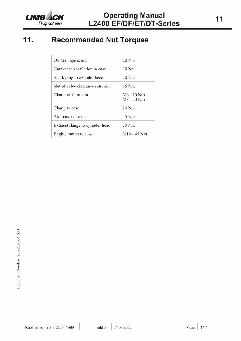
11. Recommended Nut Torques
Oil drain age screw 20 Nm
Crank case ven ti la tion to case 10 Nm
Spark plug to cyl in der head 20 Nm
Nut of valve clear ance set screw 15 Nm
Clamp to al ter na tor M6 - 10 Nm M8 - 20 Nm
Clamp to case 20 Nm
Al ter na tor to case 45 Nm
Ex haust flange to cyl in der head 20 Nm
En gine mount to case M10 - 45 Nm
00
0.1
05.
35
2.0
52 :r
eb
mu
N tn
em
uco
DOperating Manual
L2400 EF/DF/ET/DT-Series11
Repl. edition from: 22.04.1999 Edition: 04.03.2000 Page: 11-1

12. Trouble Shooting“Small”, ap par ently neglectable causes are of ten re spon si ble for a “big” ef fect, i.e. dis tur -bance of en gine op er a tion. De tec tion of the causes is not al ways easy. The hints to pos si bletrou ble causes and their cor rec tion con tained in this sec tion serve as a guide line for the en -gine user, list ing the most fre quent faults. This list of causes, how ever, does not claim forcom plete ness. Re pair work must be done only by per sons au tho rized to per form the spe cifictask.
12.1. En gine Starting Trou ble
Pos si ble Cause: Rem edy:
Bat tery dis charged or de fec tive. Charge or re place bat tery.
Bat tery wir ing not con nected to starter mo -tor or de fec tive or pos si bly in suf fi cientcon tact.
Clean con nec tors. Con nect or re place wire.
Ground wire to en gine not con nected, de -fec tive, pos si bly in suf fi cient con tact.
Clean con nec tors. Con nect or re placeground wire.
Starter mo tor de fec tive. Re pair or re place starter mo tor.
Starter re lay de fec tive. Re place starter re lay.
En gine electrics not swiched on Turn on en gine electrics
Ig ni tion har ness dis en gaged, mixed up ordam aged.
Fas ten ig ni tion lead(s) or re place. Ob servefir ing se quence 1-3-2-4. Check mark ings of con nec tors
Fuse blown in re lay box (MCU) Check fuse, re place if nec es sary
Wiring har ness or con nec tor loose or de fec -tive, wire bro ken in wir ing har ness
Check wir ing har ness and con nec tors, re -pair if nec es sary
Throt tle po ten ti om e ter de fec tive Check throt tle po ten ti om e ter. Re place ifnec es sary. Try to run en gine in emer gencymode
RPM sen sor de fec tive Check rpm sen sor. Re place if nec es -sary.Try to run en gine in emer gency mode
ECU de fec tive Re place ECU
Ig ni tion mod ule de fec tive Check ig ni tion mod ule(s). Re place if nec -es sary.
Ig ni tion coil de fec tive Check ig ni tion coil(s). Re place if nec es -sary.
Spark plugs wet due to ex cess fuel. Re move spark plugs, clean and dry. De ter -mine and elim i nate cause of ex cess fuel.
Elec trode gap of spark plug too wide. Cor rect elec trode gap to 0.7 mm or re placespark plugs.
00
0.1
05.
35
2.0
52 :r
eb
mu
N tn
em
uco
DOperating Manual
L2400 EF/DF/ET/DT-Series12
Repl. edition from: 22.04.1999 Edition: 04.03.2000 Page: 12-1
Pos si ble Cause: Rem edy:
Fuel tank empty (faulty in di ca tion of fuelgauge).
Re fuel, re place fuel gauge.
Fuel valve closed or fil ter blocked. Open fuel valve, clean or re place fil ter.
Fuel line de fec tive or not con nected. Leaksin fuel sys tem.
Re place or con nect fuel line. Re pair leaks
Fuel pump de fec tive or elec tri cal con nec -tion to fuel pump interrupted.
In ves ti gate elec tri cal sys tem and re pair ifneccessary. Replace fuel pump. Try to runen gine in emer gency mode.
Fuel pres sure reg u la tor de fec tive Check fuel pres sure, re place if nec es sary1.
Cool ant tem per a ture sen sor de fec tive Check sen sor, re place if nec es sary.
In duc tion sys tem leak age. Check in duc tion sys tem for leak age and re -place, if nec es sary, tighten joints.
Throt tle fully closed Check throt tle le ver, check idle speed ad -just ing screw.
In suf fi cient com pres sion (no valve clear -ance, leaky valves, en gine over heated).
Ad just valve clear ance, re pair cyl in derhead, tighten cyl in der heads ac cord ing tospec i fi ca tion. In ves ti gate and re move cause of over heat.
En gine de fec tive (blocked or worn out). Over haul en gine.
12.2. En gine Op er ating Trou ble
The fol low ing phe nom ena are con sid ered to be en gine op er at ing trou ble:
• un even and ir reg u lar en gine run
• tem po rary in ter rup tions
• low power
• en gine over heat
• rough en gine run
Con sider rea sons as per sec tion 12.1. be sides the ones listed be low.
00
0.1
05.
35
2.0
52 :r
eb
mu
N tn
em
uco
DOperating Manual
L2400 EF/DF/ET/DT-Series12
Repl. edition from: 22.04.1999 Edition: 04.03.2000 Page: 12-2
1 Warning Light “Fuel Pressure” is on.

12.2.1. Fuel Supply
Pos si ble Cause: Rem edy:
In suf fi cient fuel flow (Fuel ven ti la tionlocked, lines blocked or de fec tive, fil ter orscreens blocked).
Check tank ven ti la tion, lines, fil ter andscreens and re place as nec es sary.
In suf fi cient fuel pump pres sure. Check fuel pump pres sure and cor rect, ifnec es sary.
Fuel in jec tor defective Re place.
Fuel pump de fec tive. Re pair or re place fuel pump.
Fuel pres sure reg u la tor de fec tive Check fuel pres sure, re place if nec es sary.
Pres sure sen sor plugged, de fec tive. Check and clean hose to sen sor, re placesen sor if neccessary.
Cool ant tem per a ture sen sor de fec tive Check sen sor, re place if nec es sary.
Wrong idling speed. Ad just idling speed.
Throt tle does not open fully. Re pair throt tle con trol.
Air fil ter dirty or blocked Clean or re place air fil ter
In duc tion sys tem leak ing Check in duc tion sys tem for leaks and sealsys tem if nec es sary
Wrong fuel Re fill fuel tank with spec i fied fuel
12.2.2. Ignition
Pos si ble Cause: Rem edy:
Ig ni tion mod ule de fec tive. Check ig ni tion mod ule, re place if nec es sary
Ig ni tion coil de fec tive. Check ig ni tion coil, re place if nec es sary
Spark plug de fec tive. Re place spark plug.
Wrong spark plugs. Use spec i fied spark plugs.
Con nec tor on ig ni tion coils mixed Check mark ings, change over if nec es sary
Wiring har ness or con nec tor loose or de fec -tive, wire bro ken in wir ing har ness
Check wir ing har ness and con nec tors, re -pair if nec es sary
Ig ni tion switch de fec tive. Check wir ing and switch and re place asnec es sary.
Fuse in MCU de fec tive. Re place fuse, de ter mine cause (short cir -cuit) and re pair.
00
0.1
05.
35
2.0
52 :r
eb
mu
N tn
em
uco
DOperating Manual
L2400 EF/DF/ET/DT-Series12
Repl. edition from: 22.04.1999 Edition: 04.03.2000 Page: 12-3
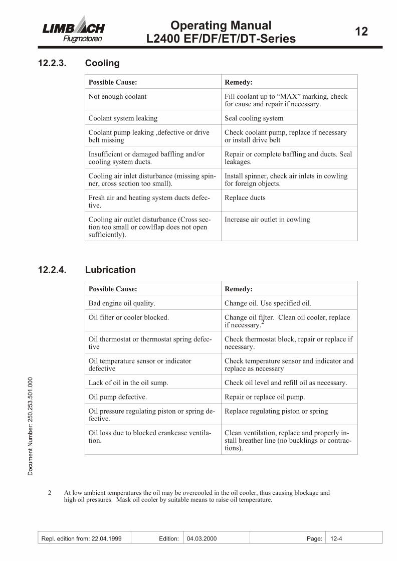
12.2.3. Cooling
Pos si ble Cause: Rem edy:
Not enough cool ant Fill cool ant up to “MAX” mark ing, checkfor cause and re pair if nec es sary.
Cool ant sys tem leak ing Seal cool ing sys tem
Cool ant pump leak ing ,de fec tive or drivebelt miss ing
Check cool ant pump, re place if nec es saryor in stall drive belt
In suf fi cient or dam aged baf fling and/orcool ing sys tem ducts.
Re pair or com plete baf fling and ducts. Sealleak ages.
Cooling air in let dis tur bance (miss ing spin -ner, cross sec tion too small).
In stall spin ner, check air in lets in cowl ingfor for eign ob jects.
Fresh air and heat ing sys tem ducts de fec -tive.
Re place ducts
Cooling air out let dis tur bance (Cross sec -tion too small or cowlflap does not opensuf fi ciently).
In crease air out let in cowl ing
12.2.4. Lubrication
Pos si ble Cause: Rem edy:
Bad en gine oil qual ity. Change oil. Use spec i fied oil.
Oil fil ter or cooler blocked. Change oil fil ter. Clean oil cooler, re placeif nec es sary.2
Oil ther mo stat or ther mo stat spring de fec -tive
Check ther mo stat block, re pair or re place if nec es sary.
Oil tem per a ture sen sor or in di ca tordefective
Check tem per a ture sen sor and in di ca tor and re place as nec es sary
Lack of oil in the oil sump. Check oil level and re fill oil as nec es sary.
Oil pump de fec tive. Re pair or re place oil pump.
Oil pres sure reg u lat ing pis ton or spring de -fec tive.
Re place reg u lat ing pis ton or spring
Oil loss due to blocked crank case ven ti la -tion.
Clean ven ti la tion, re place and prop erly in -stall breather line (no bucklings or con trac -tions).
00
0.1
05.
35
2.0
52 :r
eb
mu
N tn
em
uco
DOperating Manual
L2400 EF/DF/ET/DT-Series12
Repl. edition from: 22.04.1999 Edition: 04.03.2000 Page: 12-4
2 At low am bi ent tem per a tures the oil may be over cooled in the oil cooler, thus caus ing block age andhigh oil pres sures. Mask oil cooler by suit able means to raise oil tem per a ture.
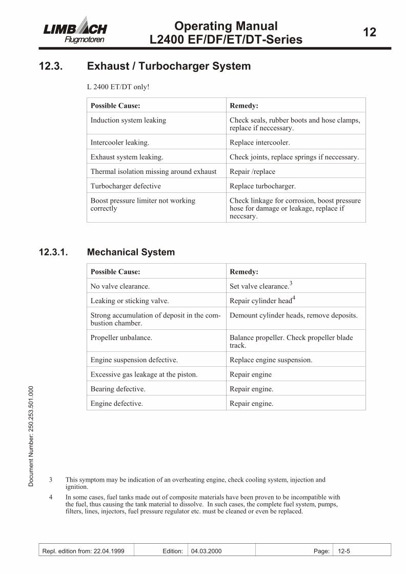
12.3. Ex haust / Turbocharger Sys tem
L 2400 ET/DT only!
Pos si ble Cause: Rem edy:
In duc tion sys tem leaking Check seals, rub ber boots and hose clamps, re place if neccessary.
Inter cool er leak ing. Re place inter cool er.
Ex haust sys tem leak ing. Check joints, re place springs if neccessary.
Ther mal iso la tion miss ing around exhaust Re pair /re place
Turbocharger defective Re place turbocharger.
Boost pres sure lim iter not work ingcorrectly
Check link age for cor ro sion, boost pres sure hose for dam age or leak age, re place ifneccsary.
12.3.1. Mechanical System
Pos si ble Cause: Rem edy:
No valve clear ance. Set valve clear ance.3
Leaking or stick ing valve. Re pair cyl in der head4
Strong ac cu mu la tion of de posit in the com -bus tion cham ber.
Demount cyl in der heads, re move de pos its.
Pro pel ler un bal ance. Bal ance pro pel ler. Check pro pel ler bladetrack.
En gine sus pen sion de fec tive. Re place en gine sus pen sion.
Ex ces sive gas leak age at the pis ton. Re pair en gine
Bear ing de fec tive. Re pair en gine.
En gine de fec tive. Re pair en gine.
00
0.1
05.
35
2.0
52 :r
eb
mu
N tn
em
uco
DOperating Manual
L2400 EF/DF/ET/DT-Series12
Repl. edition from: 22.04.1999 Edition: 04.03.2000 Page: 12-5
3 This symptom may be indication of an overheating engine, check cooling system, injection andignition.
4 In some cases, fuel tanks made out of com pos ite ma te ri als have been proven to be in com pat i ble with the fuel, thus caus ing the tank ma te rial to dis solve. In such cases, the com plete fuel sys tem, pumps,fil ters, lines, in jec tors, fuel pres sure reg u la tor etc. must be cleaned or even be re placed.
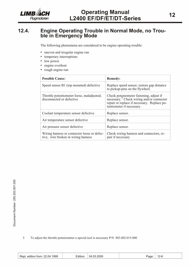
12.4. En gine Op er ating Trou ble in Nor mal Mode, no Trou -ble in Emer gency Mode
The fol low ing phe nom ena are con sid ered to be en gine op er at ing trou ble:
• un even and ir reg u lar en gine run
• tem po rary in ter rup tions
• low power
• en gine over heat
• rough en gine run
Pos si ble Cause: Rem edy:
Speed sen sor B1 (top mounted) de fec tive Re place speed sen sor, re store gap dis tanceto pickup-pins on the fly wheel.
Throt tle po ten ti om e ter loose, mal ad justed,dis con nected or de fec tive
Check poteniometer fas ten ing, ad just ifnec es sary.5 Check wir ing and/or con nec torre pair or re place if nec es sary. Re place po -ten ti om e ter if nec es sary.
Cool ant tem per a ture sen sor de fec tive Re place sen sor.
Air tem per a ture sen sor de fec tive Re place sen sor.
Air pres sure sen sor de fec tive Re place sen sor.
Wiring har ness or con nec tor loose or de fec -tive, wire bro ken in wir ing har ness
Check wir ing har ness and con nec tors, re -pair if nec es sary
00
0.1
05.
35
2.0
52 :r
eb
mu
N tn
em
uco
DOperating Manual
L2400 EF/DF/ET/DT-Series12
Repl. edition from: 22.04.1999 Edition: 04.03.2000 Page: 12-6
5 To ad just the throt tle poteniometer a spe cial tool is nec es sary P/N 803.002.015.000