limit switch type 4747 - ac controls positioners and limit... · limit switch type 4747-xxx11...
TRANSCRIPT
Edition: May 2012 EB 4747 EN
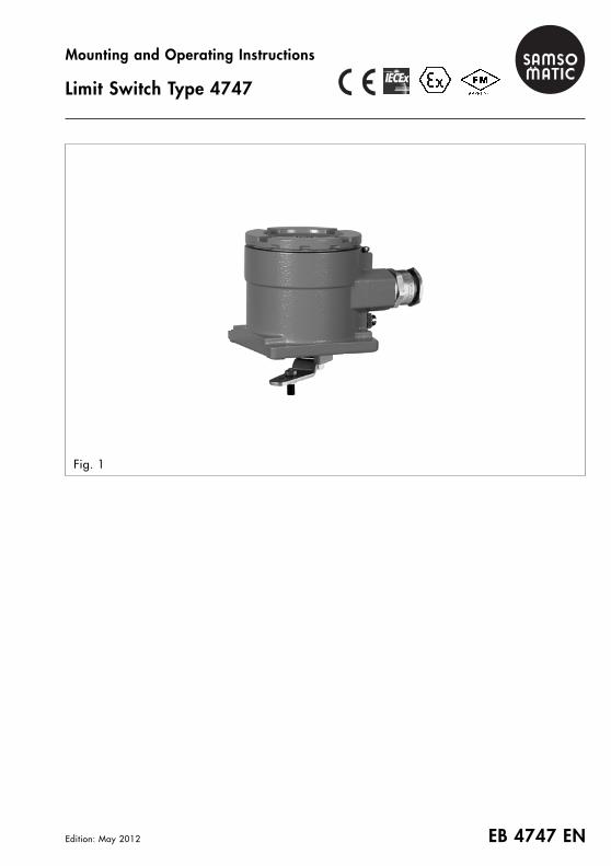
Mounting and Operating Instructions
Limit Switch Type 4747
Fig. 1
EB 4747 EN – 2 –
Contents
General notes 3Model number and device index 3Model code 3
Technical data 4
Attachment 5Attachments 5Lever and pin 6Travel tables 7Direct attachment to SAMSON Type 3277 Linear Actuators (actuator size 240/350/700 cm2) 8Direct attachment to SAMSON Type 3277-5 Linear Actuators (actuator size 120 cm2) 10Attachment to linear actuators with NAMUR rib according to IEC 60534-6-1 12Attachment to SAMSON Type 3510 Micro-flow Valves (actuator size 60 cm2) 14Attachment to rotary actuators according to VDI/VDE 3845
– fixing level 1 (heavy-duty version) 16– fixing level 2 18– fixing level 2 (heavy-duty version) 20
Attachment to VETEC Type R and Type S 160 Rotary Actuators (heavy-duty version) 22Attachment to AIR TORQUE 10000 Rotary Actuators (heavy-duty version) 24
Electrical connection 26Electrical connection in compliance with type of protection “d“ 26Connecting cable 26Degree of protection 27
Contacts 28Switching point shift due to changes in temperature 28Inductive proximity switches 29
Principle of operation 29Adjusting the switching points 29
Electric microswitches 30Principle of operation 30Adjusting the switching points 30
Servicing explosion-protected devices 31
Certification 32EC Type Examination Certificate PTB 09 ATEX 1113 X 32Certificate of Compliance (FM Approvals) 36
– 3 – EB 4747 EN
General notes
The devices are to be assembled,started up or operated only bytrained and experienced personnel
familiar with the product.
According to these mounting and operating in-structions, trained personnel referes to as indi-viduals who are able to judge the work theyare assigned to and recognize possible dan-gers due to their specialized training, theirknowledge and experience as well as theirknowledge of the applicable standards.Explosion-protected versions of this device areto be operated only by personnel who has un-dergone special training or instructions or whois authorized to work on explosion-protecteddevices in hazardous areas.Any hazards that could be caused in the valveby the process medium, the signal pressure orby moving parts are to be prevented by meansof the appropriate measures.If inadmissible motions or forces are producedin the pneumatic actuator as a result of the sup-ply pressure level, it must be restricted using asuitable supply pressure reducing station.Proper shipping and storage are assumed.For electrical installation, observe the relevantelectrotechnical regulations and the accidentprevention regulations that apply in the countryof use. In Germany, these are the VDE regula-tions and the accident prevention regulationsof the employers’ liability insurance.The following regulations apply to installationin hazardous areas: EN 60079-14:2008Explosive atmospheres – Part 14: ElectricalInstallations, design, selection and erection (orVDE 0165 Part 1) and EN 61241-14:2004Electrical Apparatus for Use in the Presence ofCombustible Dust (or VDE 0165 Part 1).For ordering data, accessories and spare partssee Data Sheet T 4747 EN.
�Model number and device index
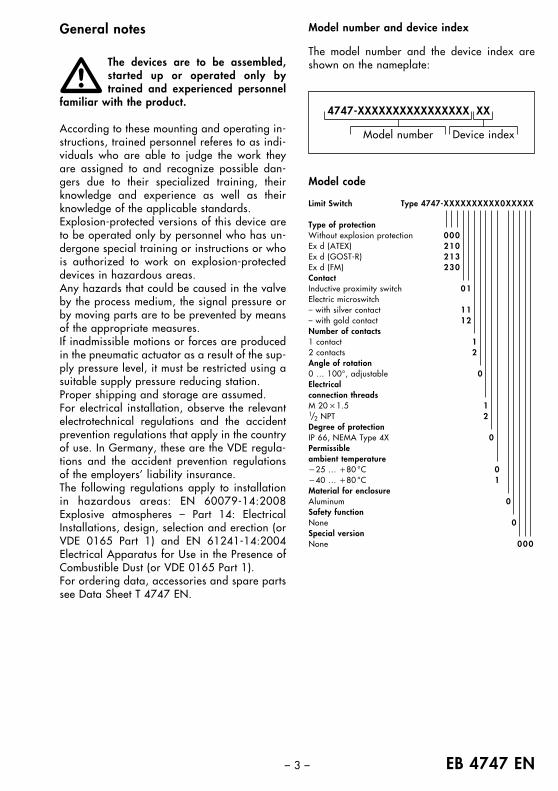
The model number and the device index areshown on the nameplate:
Device indexModel number
4747-XXXXXXXXXXXXXXXX XX
Model code
Limit Switch Type 4747-XXXXXXXXXX0XXXXX
Type of protectionWithout explosion protection 000Ex d (ATEX) 210Ex d (GOST-R) 213Ex d (FM) 230ContactInductive proximity switch 01Electric microswitch– with silver contact 11– with gold contact 12Number of contacts1 contact 12 contacts 2Angle of rotation0 … 100°, adjustable 0Electricalconnection threadsM 20 �1.5 11/2 NPT 2Degree of protectionIP 66, NEMA Type 4X 0Permissibleambient temperature�25 … �80 °C 0�40 … �80 °C 1Material for enclosureAluminum 0Safety functionNone 0Special versionNone 000
EB 4747 EN – 4 –
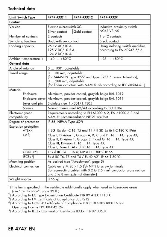
Limit Switch Type 4747-XXX11 4747-XXX12 4747-XXX01ContactVersion Electric microswitch XG Inductive proximity switch
NCB2-V3-N0Silver contact Gold contactNumber of contacts 2 contacts 1 or 2 contactsSwitching function Double-throw contact Break contactLoading capacity 250 V AC/10 A, Using isolating switch amplifier
125 V DC/ 0.5 A, according to EN 60947-5/-624 V DC/10 A
Ambient temperature 1) �40 … �80 °C �25 … �80 °CGeneral dataAngle of rotation 0 … 100°, adjustableTravel range 0 … 30 mm, adjustable
(for SAMSON Type 3277 and Type 3277-5 Linear Actuators), 0 … 200 mm, adjustable(for linear actuators with NAMUR rib according to IEC 60534-6-1)
MaterialEnclosure Aluminum, powder-coated, grayish beige RAL 1019Enclosure cover Aluminum, powder-coated, grayish beige RAL 1019Lever and pin Stainless steel 1.4301/1.4305Screws Non-corrosive steel A2/A4 according to ISO 3506
Electromagnetic Requirements according to EN 61000-6-2, EN 61000-6-3 andcompatibility NAMUR Recommendation NE 21 are metDegree of protection IP 66, NEMA Type 4X 3)Explosion protection
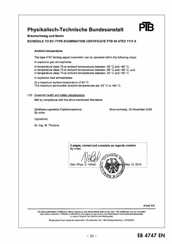
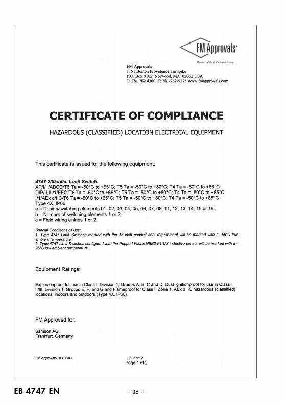
ATEX 2) II 2G Ex db IIC T6, T5 and T4 / II 2D Ex tb IIIC T80 °C IP66FM 3) Class I, Division 1, Groups A, B, C and D, T6 … T4, Type 4X,
Class II, Division 1, Groups E, F and G, T6 … T4, Type 4X,Class III, Division 1, T6 … T4, Type 4X,Class I, Zone 1, AEx d IIC T6 … T4, Type 4X
GOST-R 4) 1Ex d IIC T4 … T6 X; DIP A21 T 80 °C IP 66IECEx 5) Ex d IIC T6, T5 and T4 / Ex tD A21 IP 66 T 80 °C
Mounting position As desired (see “Attachment“, page 5)Electrical connection Cable entry M 20 �1.5 (1/2 NPT) to screw terminals
(for connecting cables with 0.2 to 2.5 mm2 conductor cross section and 5 to 8 mm external diameter)
Weight approx. 0.65 kg
Technical data
1) The limits specified in the certificate additionally apply when used in hazardous areas (see “Certification“, page 32 ff.)
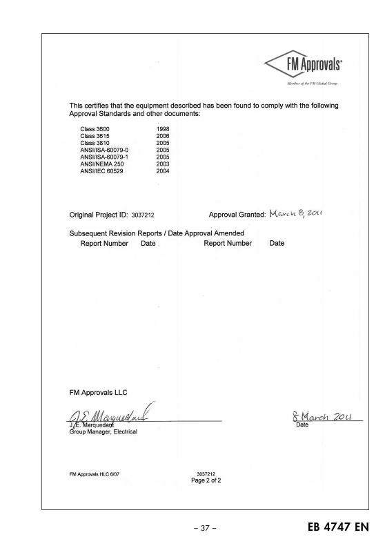
2) According to EC Type Examination Certificate PTB 09 ATEX 1113 X3) According to FM Certificate of Compliance 30372124) According to GOST-R Certificate of Compliance POCC DEGB05.B03116 and
Operating License PPC 00-0421265) According to IECEx Examination Certificate IECEx PTB 09.0060X
– 5 – EB 4747 EN
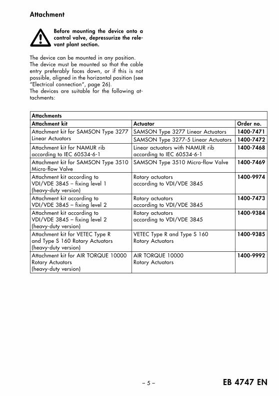
AttachmentsAttachment kit Actuator Order no.Attachment kit for SAMSON Type 3277 SAMSON Type 3277 Linear Actuators 1400-7471Linear Actuators SAMSON Type 3277-5 Linear Actuators 1400-7472Attachment kit for NAMUR rib Linear actuators with NAMUR rib 1400-7468according to IEC 60534-6-1 according to IEC 60534-6-1Attachment kit for SAMSON Type 3510 SAMSON Type 3510 Micro-flow Valve 1400-7469Micro-flow ValveAttachment kit according to Rotary actuators 1400-9974VDI/VDE 3845 – fixing level 1 according to VDI/VDE 3845(heavy-duty version)Attachment kit according to Rotary actuators 1400-7473VDI/VDE 3845 – fixing level 2 according to VDI/VDE 3845Attachment kit according to Rotary actuators 1400-9384VDI/VDE 3845 – fixing level 2 according to VDI/VDE 3845(heavy-duty version)Attachment kit for VETEC Type R VETEC Type R and Type S 160 1400-9385and Type S 160 Rotary Actuators Rotary Actuators(heavy-duty version)Attachment kit for AIR TORQUE 10000 AIR TORQUE 10000 1400-9992Rotary Actuators Rotary Actuators(heavy-duty version)
Attachment
Before mounting the device onto acontrol valve, depressurize the rele-vant plant section.
The device can be mounted in any position.The device must be mounted so that the cableentry preferably faces down, or if this is notpossible, aligned in the horizontal position (see“Electrical connection“, page 26).The devices are suitable for the following at-tachments:
�
EB 4747 EN – 6 –
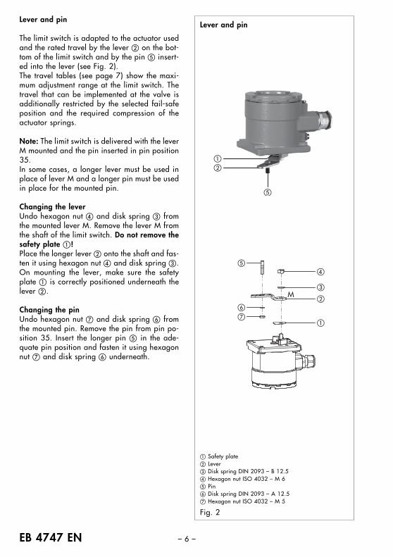
Lever and pin
The limit switch is adapted to the actuator usedand the rated travel by the lever � on the bot-tom of the limit switch and by the pin � insert-ed into the lever (see Fig. 2).The travel tables (see page 7) show the maxi-mum adjustment range at the limit switch. Thetravel that can be implemented at the valve isadditionally restricted by the selected fail-safeposition and the required compression of theactuator springs.
Note: The limit switch is delivered with the leverM mounted and the pin inserted in pin position35.In some cases, a longer lever must be used inplace of lever M and a longer pin must be usedin place for the mounted pin.
Changing the leverUndo hexagon nut � and disk spring � fromthe mounted lever M. Remove the lever M fromthe shaft of the limit switch. Do not remove thesafety plate �!Place the longer lever � onto the shaft and fas-ten it using hexagon nut � and disk spring �.On mounting the lever, make sure the safetyplate � is correctly positioned underneath thelever �.
Changing the pinUndo hexagon nut � and disk spring � fromthe mounted pin. Remove the pin from pin po-sition 35. Insert the longer pin � in the ade-quate pin position and fasten it using hexagonnut � and disk spring � underneath.
Lever and pin
M
� Safety plate� Lever� Disk spring DIN 2093 – B 12.5� Hexagon nut ISO 4032 – M 6� Pin� Disk spring DIN 2093 – A 12.5� Hexagon nut ISO 4032 – M 5
Fig. 2
– 7 – EB 4747 EN
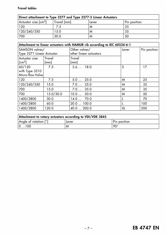
Direct attachment to Type 3277 and Type 3277-5 Linear ActuatorsActuator size [cm2] Travel [mm] Lever Pin position120 7.5 M 25120/240/350 15.0 M 35700 30.0 M 50
Travel tables
Attachment to linear actuators with NAMUR rib according to IEC 60534-6-1SAMSON valves/ Other valves/ Lever Pin positionType 3271 Linear Actuator other linear actuatorsActuator size Travel Travel[cm2] [mm] [mm]60/120 7.5 3.6 … 18.0 S 17with Type 3510Micro-flow Valve120 7.5 5.0 … 25.0 M 25120/240/350 15.0 7.0 … 35.0 M 35700 15.0 7.0 … 35.0 M 35700 15.0/30.0 10.0 … 50.0 M 501400/2800 30.0 14.0 … 70.0 L 701400/2800 60.0 20.0 … 100.0 L 1001400/2800 120.0 40.0 … 200.0 XL 200
Attachment to rotary actuators according to VDI/VDE 3845Angle of rotation [°] Lever Pin position0 …100 M 90°
EB 4747 EN – 8 –
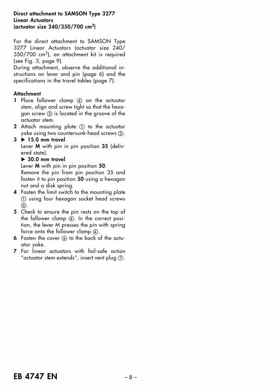
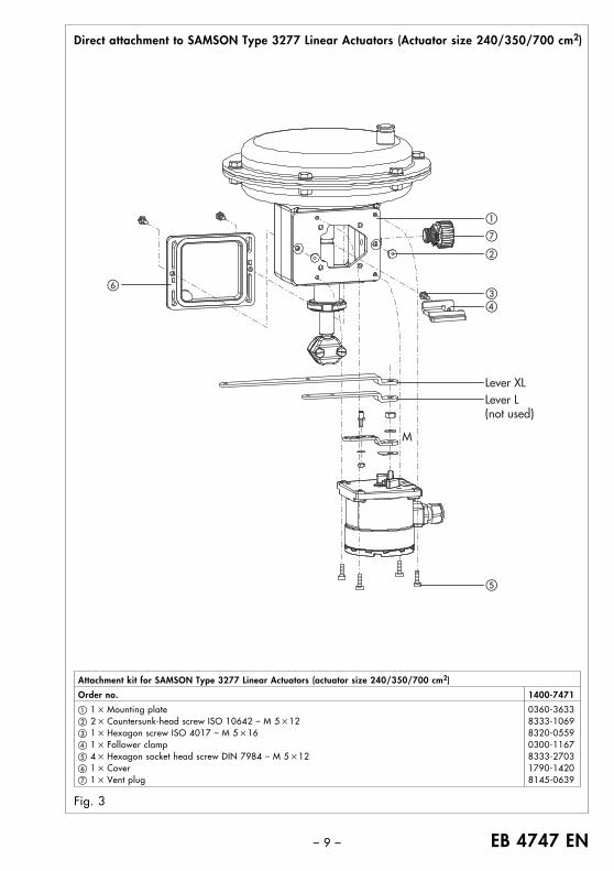
Direct attachment to SAMSON Type 3277 Linear Actuators(actuator size 240/350/700 cm2)
For the direct attachment to SAMSON Type3277 Linear Actuators (actuator size 240/350/700 cm2), an attachment kit is required(see Fig. 3, page 9).During attachment, observe the additional in-structions on lever and pin (page 6) and thespecifications in the travel tables (page 7).
Attachment1 Place follower clamp � on the actuator
stem, align and screw tight so that the hexa-gon screw � is located in the groove of theactuator stem.
2 Attach mounting plate � to the actuatoryoke using two countersunk-head screws �.
3 � 15.0 mm travelLever M with pin in pin position 35 (deliv-ered state).� 30.0 mm travelLever M with pin in pin position 50.Remove the pin from pin position 35 andfasten it to pin position 50 using a hexagonnut and a disk spring.
4 Fasten the limit switch to the mounting plate� using four hexagon socket head screws�.
5 Check to ensure the pin rests on the top ofthe follower clamp �. In the correct posi-tion, the lever M presses the pin with springforce onto the follower clamp �.
6 Fasten the cover � to the back of the actu-ator yoke.
7 For linear actuators with fail-safe action“actuator stem extends“, insert vent plug �.
– 9 – EB 4747 EN
Direct attachment to SAMSON Type 3277 Linear Actuators (Actuator size 240/350/700 cm2)
Fig. 3
Attachment kit for SAMSON Type 3277 Linear Actuators (actuator size 240/350/700 cm2)
Order no. 1400-7471
� 1 � Mounting plate 0360-3633� 2 � Countersunk-head screw ISO 10642 – M 5 �12 8333-1069� 1 � Hexagon screw ISO 4017 – M 5 �16 8320-0559� 1 � Follower clamp 0300-1167� 4 � Hexagon socket head screw DIN 7984 – M 5 �12 8333-2703� 1 � Cover 1790-1420� 1 � Vent plug 8145-0639
�
�
�
�
��
Lever L (not used)
Lever XL
�
M
EB 4747 EN – 10 –
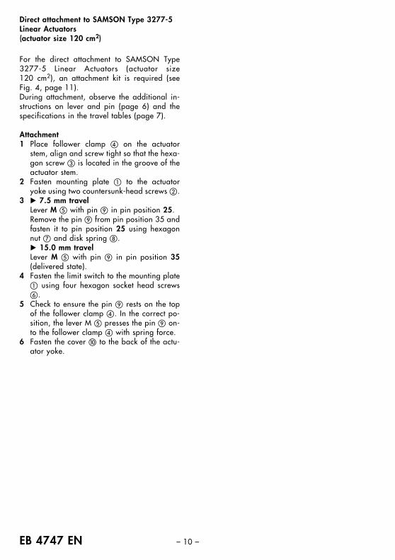
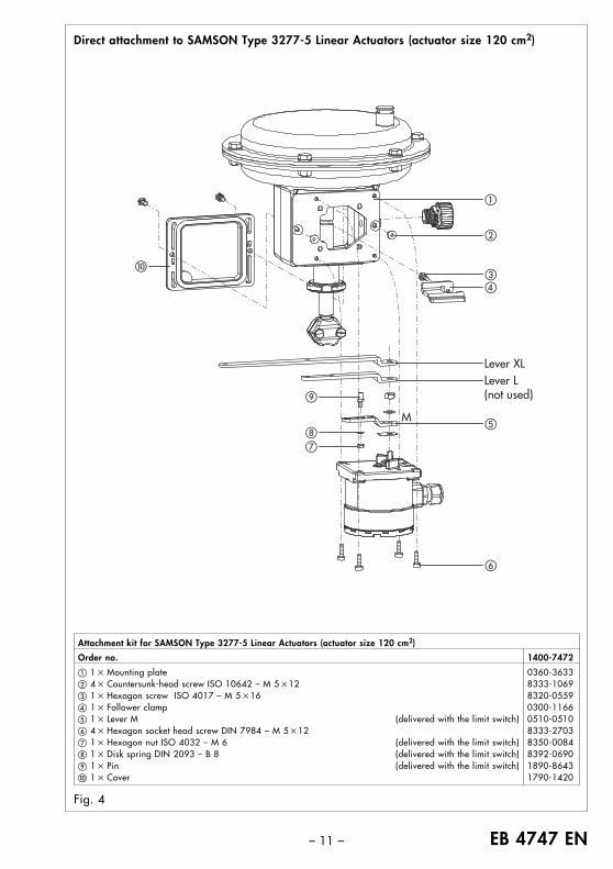
Direct attachment to SAMSON Type 3277-5 Linear Actuators(actuator size 120 cm2)
For the direct attachment to SAMSON Type3277-5 Linear Actuators (actuator size 120 cm2), an attachment kit is required (seeFig. 4, page 11).During attachment, observe the additional in-structions on lever and pin (page 6) and thespecifications in the travel tables (page 7).
Attachment1 Place follower clamp � on the actuator
stem, align and screw tight so that the hexa-gon screw � is located in the groove of theactuator stem.
2 Fasten mounting plate � to the actuatoryoke using two countersunk-head screws �.
3 � 7.5 mm travelLever M � with pin in pin position 25.Remove the pin from pin position 35 andfasten it to pin position 25 using hexagonnut � and disk spring .� 15.0 mm travelLever M � with pin in pin position 35(delivered state).
4 Fasten the limit switch to the mounting plate� using four hexagon socket head screws�.
5 Check to ensure the pin rests on the topof the follower clamp �. In the correct po-sition, the lever M � presses the pin on-to the follower clamp � with spring force.
6 Fasten the cover � to the back of the actu-ator yoke.
– 11 – EB 4747 EN
Direct attachment to SAMSON Type 3277-5 Linear Actuators (actuator size 120 cm2)
Fig. 4
Attachment kit for SAMSON Type 3277-5 Linear Actuators (actuator size 120 cm2)
Order no. 1400-7472
� 1 � Mounting plate 0360-3633� 4 � Countersunk-head screw ISO 10642 – M 5 �12 8333-1069� 1 � Hexagon screw ISO 4017 – M 5 �16 8320-0559� 1 � Follower clamp 0300-1166� 1 � Lever M (delivered with the limit switch) 0510-0510� 4 � Hexagon socket head screw DIN 7984 – M 5 �12 8333-2703� 1 � Hexagon nut ISO 4032 – M 6 (delivered with the limit switch) 8350-0084 1 � Disk spring DIN 2093 – B 8 (delivered with the limit switch) 8392-0690 1 � Pin (delivered with the limit switch) 1890-8643� 1 � Cover 1790-1420
�
�
�
�
�
�
��
Lever L (not used)
Lever XL
M
EB 4747 EN – 12 –
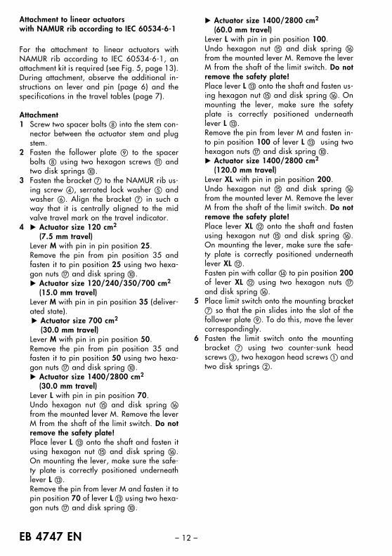
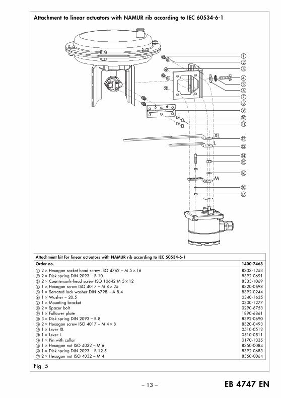
Attachment to linear actuators with NAMUR rib according to IEC 60534-6-1
For the attachment to linear actuators withNAMUR rib according to IEC 60534-6-1, anattachment kit is required (see Fig. 5, page 13).During attachment, observe the additional in-structions on lever and pin (page 6) and thespecifications in the travel tables (page 7).
Attachment1 Screw two spacer bolts into the stem con-
nector between the actuator stem and plugstem.
2 Fasten the follower plate to the spacerbolts using two hexagon screws � andtwo disk springs �.
3 Fasten the bracket � to the NAMUR rib us-ing screw �, serrated lock washer � andwasher �. Align the bracket � in such away that it is centrally aligned to the midvalve travel mark on the travel indicator.
4 � Actuator size 120 cm2
(7.5 mm travel)Lever M with pin in pin position 25.Remove the pin from pin position 35 andfasten it to pin position 25 using two hexa-gon nuts and disk spring �.� Actuator size 120/240/350/700 cm2
(15.0 mm travel)Lever M with pin in pin position 35 (deliver-ated state).� Actuator size 700 cm2
(30.0 mm travel)Lever M with pin in pin position 50.Remove the pin from pin position 35 andfasten it to pin position 50 using two hexa-gon nuts and disk spring �.� Actuator size 1400/2800 cm2
(30.0 mm travel)Lever L with pin in pin position 70.Undo hexagon nut � and disk spring �from the mounted lever M. Remove the leverM from the shaft of the limit switch. Do notremove the safety plate!Place lever L � onto the shaft and fasten itusing hexagon nut � and disk spring �.On mounting the lever, make sure the safe-ty plate is correctly positioned underneathlever L �.Remove the pin from lever M and fasten it topin position 70 of lever L � using two hexa-gon nuts and disk spring �.
� Actuator size 1400/2800 cm2
(60.0 mm travel)Lever L with pin in pin position 100.Undo hexagon nut � and disk spring �from the mounted lever M. Remove the leverM from the shaft of the limit switch. Do notremove the safety plate!Place lever L � onto the shaft and fasten us-ing hexagon nut � and disk spring �. Onmounting the lever, make sure the safetyplate is correctly positioned underneathlever L �.Remove the pin from lever M and fasten in-to pin position 100 of lever L � using twohexagon nuts and disk spring �.� Actuator size 1400/2800 cm2
(120.0 mm travel)Lever XL with pin in pin position 200.Undo hexagon nut � and disk spring �from the mounted lever M. Remove the leverM from the shaft of the limit switch. Do notremove the safety plate!Place lever XL � onto the shaft and fastenusing hexagon nut � and disk spring �.On mounting the lever, make sure the safe-ty plate is correctly positioned underneathlever XL �.Fasten pin with collar � to pin position 200of lever XL � using two hexagon nuts and disk spring �.
5 Place limit switch onto the mounting bracket� so that the pin slides into the slot of thefollower plate . To do this, move the levercorrespondingly.
6 Fasten the limit switch onto the mountingbracket � using two counter-sunk headscrews �, two hexagon head screws � andtwo disk springs �.
– 13 – EB 4747 EN
Attachment to linear actuators with NAMUR rib according to IEC 60534-6-1
Fig. 5
Attachment kit for linear actuators with NAMUR rib according to IEC 50534-6-1
Order no. 1400-7468
� 2 � Hexagon socket head screw ISO 4762 – M 5 �16 8333-1253� 2 � Disk spring DIN 2093 – B 10 8392-0691� 2 � Countersunk-head screw ISO 10642 M 5 �12 8333-1069� 1 � Hexagon screw ISO 4017 – M 8 � 25 8320-0698� 1 � Serrated lock washer DIN 6798 – A 8.4 8392-0244� 1 � Washer – 20.5 0340-1635� 1 � Mounting bracket 0300-1277 2 � Spacer bolt 0290-6753 1 � Follower plate 1890-6861� 3 � Disk spring DIN 2093 – B 8 8392-0690� 2 � Hexagon screw ISO 4017 – M 4 � 8 8320-0493� 1 � Lever XL 0510-0512� 1 � Lever L 0510-0511� 1 � Pin with collar 0170-1335� 1 � Hexagon nut ISO 4032 – M 6 8350-0084� 1 � Disk spring DIN 2093 – B 12.5 8392-0683 2 � Hexagon nut ISO 4032 – M 4 8350-0064
�
�
�
�
��
�
�
���
�
�
�
�
M
XLL
EB 4747 EN – 14 –
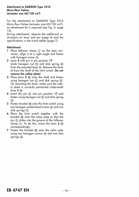
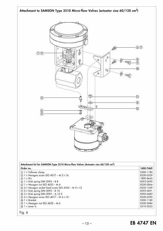
Attachment to SAMSON Type 3510 Micro-flow Valves(actuator size 60/120 cm2)
For the attachment to SAMSON Type 3510Micro-flow Valves (actuator size 60/120 cm2),an attachment kit is required (see Fig. 6, page15).During attachment, observe the additional in-structions on lever and pin (page 6) and thespecifications in the travel tables (page 7).
Attachment1 Place follower clamp � on the stem con-
nector, align it at a right angle and fastenwith hexagon screw �.
2 Lever S with pin in pin position 17.Undo hexagon nut � and disk spring from the mounted lever M. Remove the leverM from the shaft of the limit switch. Do notremove the safety plate!
3 Place lever S � onto the shaft and fastenusing hexagon nut � and disk spring .On mounting the lever, make sure the safe-ty plate is correctly positioned underneathlever S �.
4 Insert the pin � into pin position 17 andfasten using hexagon nut � and disk spring�.
5 Fasten bracket � onto the limit switch usingtwo hexagon socket head screws � and twodisk springs �.
6 Place the limit switch together with thebracket � onto the valve yoke so that thepin � slides into the groove of the followerclamp �. To do this, move the lever S �correspondingly.
7 Fasten the bracket � onto the valve yokeusing two hexagon screws and two disksprings .
– 15 – EB 4747 EN
Attachment to SAMSON Type 3510 Micro-flow Valves (actuator size 60/120 cm2)
Fig. 6
Attachment kit for SAMSON Type 3510 Micro-flow Valves (Actuator size 60/120 cm2)
Order no. 1400-7469
� 1 � Follower clamp 0300-1180� 1 � Hexagon screw ISO 4017 – M 5 �16 8320-0559� 1 � Pin 1890-8643� 1 � Disk spring DIN 2093 – B 8 8392-0690� 1 � Hexagon nut ISO 4032 – M 4 8350-0064� 2 � Hexagon socket head screw ISO 4762 – M 5 �12 8333-1249� 2 � Disk spring DIN 2093 – B 10 8392-0691 3 � Disk spring DIN 2093 – A 12.5 8392-0683 2 � Hexagon screw ISO 4017 – M 6 �10 8320-0590� 1 � Bracket 0300-1180� 1 � Hexagon nut ISO 4032 – M 6 8350-0084� 1 � Lever S 0510-0522
�
�
� �
�
� �
�
��
S
EB 4747 EN – 16 –
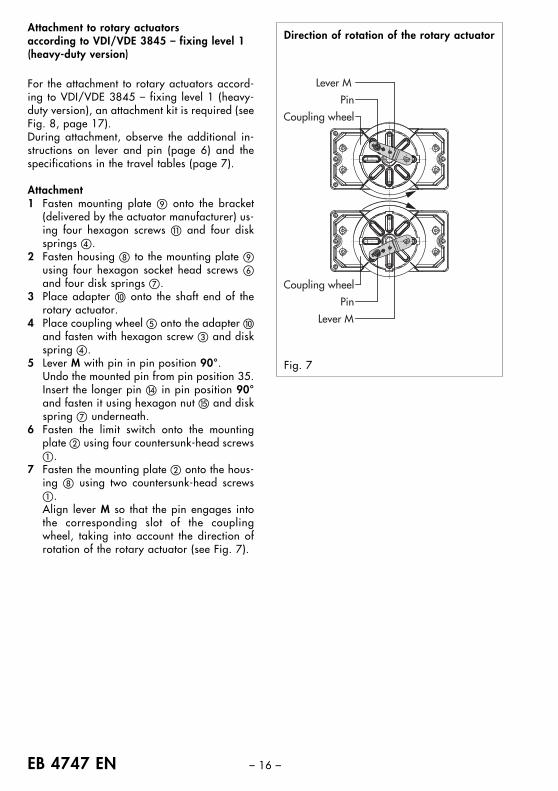
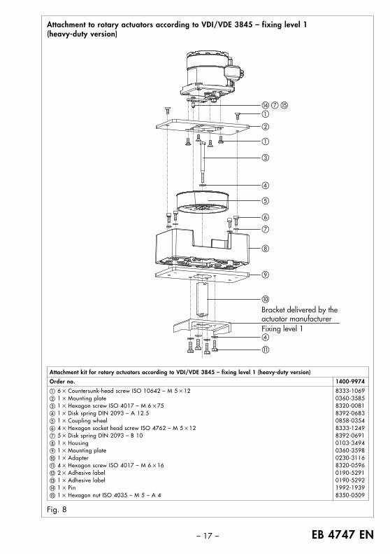
Attachment to rotary actuators according to VDI/VDE 3845 – fixing level 1 (heavy-duty version)
For the attachment to rotary actuators accord-ing to VDI/VDE 3845 – fixing level 1 (heavy-duty version), an attachment kit is required (seeFig. 8, page 17).During attachment, observe the additional in-structions on lever and pin (page 6) and thespecifications in the travel tables (page 7).
Attachment1 Fasten mounting plate onto the bracket
(delivered by the actuator manufacturer) us-ing four hexagon screws � and four disksprings �.
2 Fasten housing to the mounting plate using four hexagon socket head screws �and four disk springs �.
3 Place adapter � onto the shaft end of therotary actuator.
4 Place coupling wheel � onto the adapter �and fasten with hexagon screw � and diskspring �.
5 Lever M with pin in pin position 90°.Undo the mounted pin from pin position 35.Insert the longer pin � in pin position 90°and fasten it using hexagon nut � and diskspring � underneath.
6 Fasten the limit switch onto the mountingplate � using four countersunk-head screws�.
7 Fasten the mounting plate � onto the hous-ing using two countersunk-head screws�.Align lever M so that the pin engages intothe corresponding slot of the couplingwheel, taking into account the direction ofrotation of the rotary actuator (see Fig. 7).
Pin
Coupling wheel
Lever M
Lever M
Pin
Coupling wheel
Fig. 7
Direction of rotation of the rotary actuator
– 17 – EB 4747 EN
Attachment to rotary actuators according to VDI/VDE 3845 – fixing level 1(heavy-duty version)
Fig. 8
�
�
�
�
�
�
�
�
�
�
�
� � �
Bracket delivered by the actuator manufacturerFixing level 1
Attachment kit for rotary actuators according to VDI/VDE 3845 – fixing level 1 (heavy-duty version)
Order no. 1400-9974
� 6 � Countersunk-head screw ISO 10642 – M 5 �12 8333-1069� 1 � Mounting plate 0360-3585� 1 � Hexagon screw ISO 4017 – M 6 �75 8320-0081� 1 � Disk spring DIN 2093 – A 12.5 8392-0683� 1 � Coupling wheel 0858-0354� 4 � Hexagon socket head screw ISO 4762 – M 5 �12 8333-1249� 5 � Disk spring DIN 2093 – B 10 8392-0691 1 � Housing 0103-3494 1 � Mounting plate 0360-3598� 1 � Adapter 0230-3116� 4 � Hexagon screw ISO 4017 – M 6 �16 8320-0596� 2 � Adhesive label 0190-5291� 1 � Adhesive label 0190-5292� 1 � Pin 1992-1939� 1 � Hexagon nut ISO 4035 – M 5 – A 4 8350-0509

EB 4747 EN – 18 –
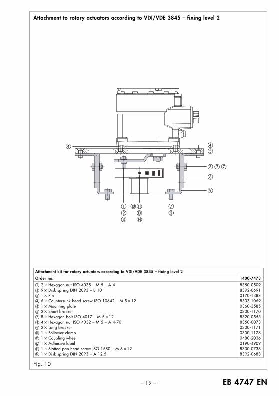
Attachment to rotary actuators according to VDI/VDE 3845 – fixing level 2
For the attachment to rotary actuators accord-ing to VDI/VDE 3845 – fixing level 2, anattachment kit is required (see Fig. 10, page19).During attachment, observe the additional in-structions to lever and pin (page 6) and thespecifications in the travel tables (page 7).
Attachment1 Fasten both long brackets to the rotary
actuator using two hexagon screws � andtwo disk springs � for each bracket.
2 Fasten both short brackets � to the longbrackets using two hexagon screws �,two disk springs � and two hexagon nuts for each bracket.
3 Place the follower clamp � on the shaft endof the rotary actuator.
4 Place the coupling wheel � on the followerclamp � and fasten using slotted pan headscrew � and disk spring �.
5 Lever M with pin in pin position 90°.Undo the mounted pin from pin position 35.Insert the longer pin � in pin position 90°and fasten it using hexagon nut � and diskspring � underneath.
6 Fasten the limit switch onto the mountingplate � using four countersunk-head screws�.
7 Fasten the mounting plate � to the shortbrackets � using two countersunk-headscrews �.Align lever M so that the pin engages intothe corresponding slot of the couplingwheel, taking into account the direction ofrotation of the rotary actuator (see Fig. 9).
Pin
Coupling wheel
Lever M
Lever M
Pin
Coupling wheel
Fig. 9
Direction of rotation of the rotary actuator
– 19 – EB 4747 EN
Attachment to rotary actuators according to VDI/VDE 3845 – fixing level 2
Fig. 10
Attachment kit for rotary actuators according to VDI/VDE 3845 – fixing level 2
Order no. 1400-7473
� 2 � Hexagon nut ISO 4035 – M 5 – A 4 8350-0509� 9 � Disk spring DIN 2093 – B 10 8392-0691� 1 � Pin 0170-1388� 6 � Countersunk-head screw ISO 10642 – M 5 �12 8333-1069� 1 � Mounting plate 0360-3585� 2 � Short bracket 0300-1170� 8 � Hexagon bolt ISO 4017 – M 5 �12 8320-0553 4 � Hexagon nut ISO 4032 – M 5 – A 4-70 8350-0073 2 � Long bracket 0300-1171� 1 � Follower clamp 0300-1176� 1 � Coupling wheel 0480-2036� 1 � Adhesive label 0190-4909� 1 � Slotted pan head screw ISO 1580 – M 6 �12 8330-0736� 1 � Disk spring DIN 2093 – A 12.5 8392-0683
��
� �
�
�
���
���
� ��
EB 4747 EN – 20 –
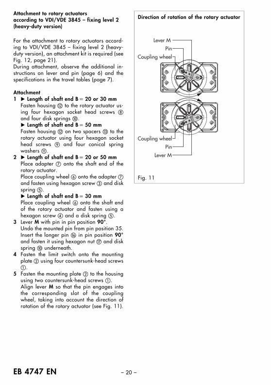
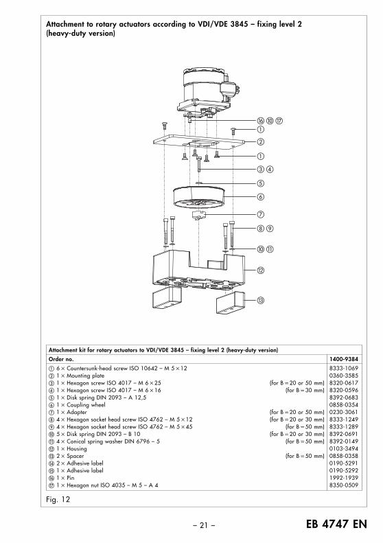
Attachment to rotary actuators according to VDI/VDE 3845 – fixing level 2 (heavy-duty version)
For the attachment to rotary actuators accord-ing to VDI/VDE 3845 – fixing level 2 (heavy-duty version), an attachment kit is required (seeFig. 12, page 21).During attachment, observe the additional in-structions on lever and pin (page 6) and thespecifications in the travel tables (page 7).
Attachment1 � Length of shaft end B � 20 or 30 mm
Fasten housing � to the rotary actuator us-ing four hexagon socket head screws and four disk springs �.� Length of shaft end B � 50 mmFasten housing � on two spacers � to therotary actuator using four hexagon sockethead screws and four conical springwashers �.
2 � Length of shaft end B � 20 or 50 mmPlace adapter � onto the shaft end of therotary actuator.Place coupling wheel � onto the adapter �and fasten using hexagon screw � and diskspring �.� Length of shaft end B � 30 mmPlace coupling wheel � onto the shaft endof the rotary actuator and fasten using ahexagon screw � and a disk spring �.
3 Lever M with pin in pin position 90°.Undo the mounted pin from pin position 35.Insert the longer pin � in pin position 90°and fasten it using hexagon nut and diskspring � underneath.
4 Fasten the limit switch onto the mountingplate � using four countersunk-head screws�.
5 Fasten the mounting plate � to the housingusing two countersunk-head screws �.Align lever M so that the pin engages intothe corresponding slot of the couplingwheel, taking into account the direction ofrotation of the rotary actuator (see Fig. 11).
Pin
Coupling wheel
Lever M
Lever M
Pin
Coupling wheel
Fig. 11
Direction of rotation of the rotary actuator
– 21 – EB 4747 EN
Attachment to rotary actuators according to VDI/VDE 3845 – fixing level 2 (heavy-duty version)
Fig. 12
Attachment kit for rotary actuators to VDI/VDE 3845 – fixing level 2 (heavy-duty version)
Order no. 1400-9384
� 6 � Countersunk-head screw ISO 10642 – M 5 �12 8333-1069� 1 � Mounting plate 0360-3585� 1 � Hexagon screw ISO 4017 – M 6 �25 (for B �20 or 50 mm) 8320-0617� 1 � Hexagon screw ISO 4017 – M 6 �16 (for B �30 mm) 8320-0596� 1 � Disk spring DIN 2093 – A 12,5 8392-0683� 1 � Coupling wheel 0858-0354� 1 � Adapter (for B �20 or 50 mm) 0230-3061 4 � Hexagon socket head screw ISO 4762 – M 5 �12 (for B �20 or 30 mm) 8333-1249 4 � Hexagon socket head screw ISO 4762 – M 5 �45 (for B �50 mm) 8333-1289� 5 � Disk spring DIN 2093 – B 10 (for B �20 or 30 mm) 8392-0691� 4 � Conical spring washer DIN 6796 – 5 (for B �50 mm) 8392-0149� 1 � Housing 0103-3494� 2 � Spacer (for B �50 mm) 0858-0358� 2 � Adhesive label 0190-5291� 1 � Adhesive label 0190-5292� 1 � Pin 1992-1939 1 � Hexagon nut ISO 4035 – M 5 – A 4 8350-0509
�
�
�
� �
�
� �
�
�
� �
�
�
EB 4747 EN – 22 –
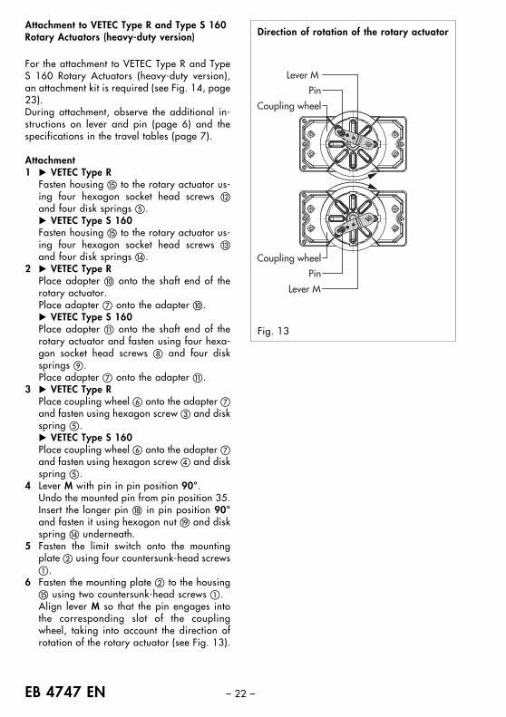
Attachment to VETEC Type R and Type S 160 Rotary Actuators (heavy-duty version)
For the attachment to VETEC Type R and TypeS 160 Rotary Actuators (heavy-duty version),an attachment kit is required (see Fig. 14, page23).During attachment, observe the additional in-structions on lever and pin (page 6) and thespecifications in the travel tables (page 7).
Attachment1 � VETEC Type R
Fasten housing � to the rotary actuator us-ing four hexagon socket head screws �and four disk springs �.� VETEC Type S 160Fasten housing � to the rotary actuator us-ing four hexagon socket head screws �and four disk springs �.
2 � VETEC Type RPlace adapter � onto the shaft end of therotary actuator.Place adapter � onto the adapter �.� VETEC Type S 160Place adapter � onto the shaft end of therotary actuator and fasten using four hexa-gon socket head screws and four disksprings .Place adapter � onto the adapter �.
3 � VETEC Type RPlace coupling wheel � onto the adapter �and fasten using hexagon screw � and diskspring �.� VETEC Type S 160Place coupling wheel � onto the adapter �and fasten using hexagon screw � and diskspring �.
4 Lever M with pin in pin position 90°.Undo the mounted pin from pin position 35.Insert the longer pin � in pin position 90°and fasten it using hexagon nut � and diskspring � underneath.
5 Fasten the limit switch onto the mountingplate � using four countersunk-head screws�.
6 Fasten the mounting plate � to the housing� using two countersunk-head screws �.Align lever M so that the pin engages intothe corresponding slot of the couplingwheel, taking into account the direction ofrotation of the rotary actuator (see Fig. 13).
Pin
Coupling wheel
Lever M
Lever M
Pin
Coupling wheel
Fig. 13
Direction of rotation of the rotary actuator
– 23 – EB 4747 EN
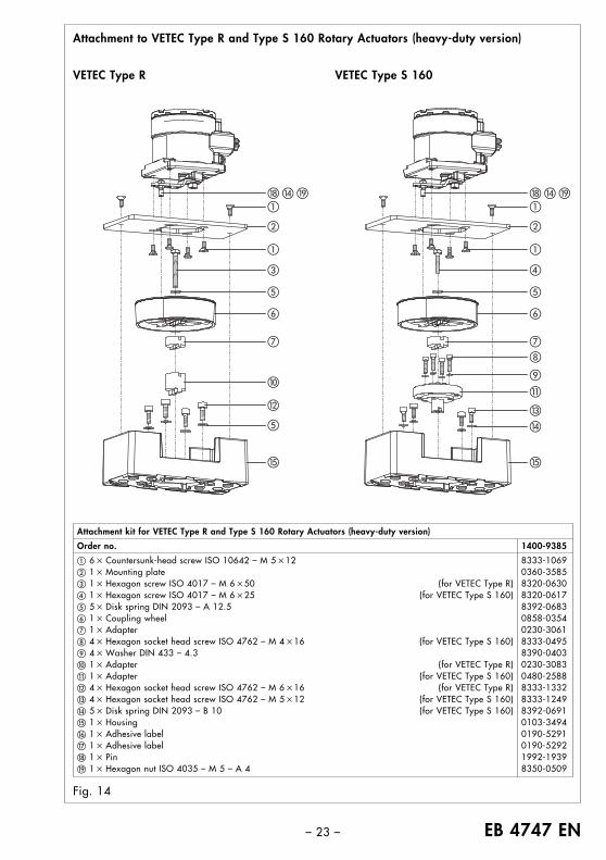
Attachment to VETEC Type R and Type S 160 Rotary Actuators (heavy-duty version)
Fig. 14
Attachment kit for VETEC Type R and Type S 160 Rotary Actuators (heavy-duty version)
Order no. 1400-9385
� 6 � Countersunk-head screw ISO 10642 – M 5 �12 8333-1069� 1 � Mounting plate 0360-3585� 1 � Hexagon screw ISO 4017 – M 6 �50 (for VETEC Type R) 8320-0630� 1 � Hexagon screw ISO 4017 – M 6 �25 (for VETEC Type S 160) 8320-0617� 5 � Disk spring DIN 2093 – A 12.5 8392-0683� 1 � Coupling wheel 0858-0354� 1 � Adapter 0230-3061 4 � Hexagon socket head screw ISO 4762 – M 4 �16 (for VETEC Type S 160) 8333-0495 4 � Washer DIN 433 – 4.3 8390-0403� 1 � Adapter (for VETEC Type R) 0230-3083� 1 � Adapter (for VETEC Type S 160) 0480-2588� 4 � Hexagon socket head screw ISO 4762 – M 6 �16 (for VETEC Type R) 8333-1332� 4 � Hexagon socket head screw ISO 4762 – M 5 �12 (for VETEC Type S 160) 8333-1249� 5 � Disk spring DIN 2093 – B 10 (for VETEC Type S 160) 8392-0691� 1 � Housing 0103-3494� 1 � Adhesive label 0190-5291 1 � Adhesive label 0190-5292� 1 � Pin 1992-1939� 1 � Hexagon nut ISO 4035 – M 5 – A 4 8350-0509
�
�
�
�
�
�
�
�
�
�
�
� � � � � �
�
�
�
�
�
�
�
�
�
�
�
VETEC Type R VETEC Type S 160
EB 4747 EN – 24 –
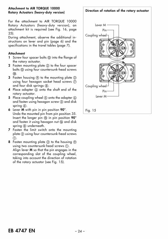
Attachment to AIR TORQUE 10000 Rotary Actuators (heavy-duty version)
For the attachment to AIR TORQUE 10000Rotary Actuators (heavy-duty version), anattachment kit is required (see Fig. 16, page25).During attachment, observe the additional in-structions on lever and pin (page 6) and thespecifications in the travel tables (page 7).
Attachment1 Screw four spacer bolts � into the flange of
the rotary actuator.2 Fasten mounting plate � to the four spacer
bolts � using four countersunk-head screws�.
3 Fasten housing to the mounting plate �using four hexagon socket head screws �and four disk springs .
4 Place adapter � onto the shaft end of therotary actuator.
5 Place coupling wheel � onto the adapter �and fasten using hexagon screw � and diskspring �.
6 Lever M with pin in pin position 90°.Undo the mounted pin from pin position 35.Insert the longer pin � in pin position 90°and fasten it using hexagon nut � and diskspring underneath.
7 Fasten the limit switch onto the mountingplate � using four countersunk-head screws�.
8 Fasten mounting plate � to the housing using two countersunk-head screws �.Align lever M so that the pin engages in thecorresponding slot of the coupling wheel,taking into account the direction of rotationof the rotary actuator (see Fig. 15).
Pin
Coupling wheel
Lever M
Lever M
Pin
Coupling wheel
Fig. 15
Direction of rotation of the rotary actuator
– 25 – EB 4747 EN
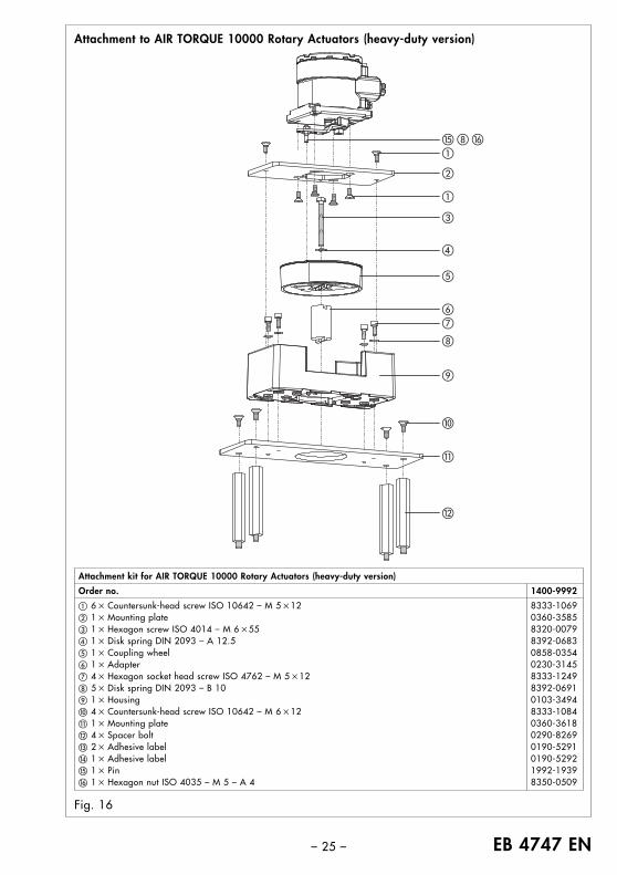
Attachment to AIR TORQUE 10000 Rotary Actuators (heavy-duty version)
Fig. 16
Attachment kit for AIR TORQUE 10000 Rotary Actuators (heavy-duty version)
Order no. 1400-9992
� 6 � Countersunk-head screw ISO 10642 – M 5 �12 8333-1069� 1 � Mounting plate 0360-3585� 1 � Hexagon screw ISO 4014 – M 6 �55 8320-0079� 1 � Disk spring DIN 2093 – A 12.5 8392-0683� 1 � Coupling wheel 0858-0354� 1 � Adapter 0230-3145� 4 � Hexagon socket head screw ISO 4762 – M 5 �12 8333-1249 5 � Disk spring DIN 2093 – B 10 8392-0691 1 � Housing 0103-3494� 4 � Countersunk-head screw ISO 10642 – M 6 �12 8333-1084� 1 � Mounting plate 0360-3618� 4 � Spacer bolt 0290-8269� 2 � Adhesive label 0190-5291� 1 � Adhesive label 0190-5292� 1 � Pin 1992-1939� 1 � Hexagon nut ISO 4035 – M 5 – A 4 8350-0509
�
�
�
�
�
�
�
�
�
�
�
� �
EB 4747 EN – 26–
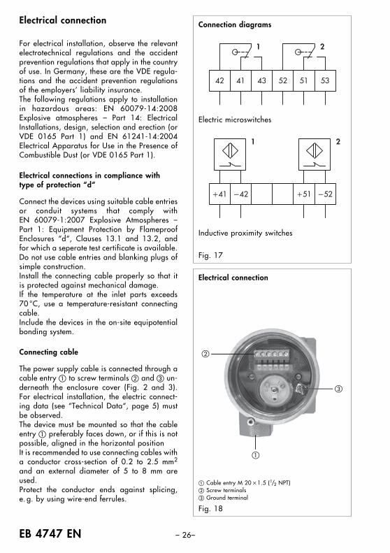
Electrical connection
For electrical installation, observe the relevantelectrotechnical regulations and the accidentprevention regulations that apply in the countryof use. In Germany, these are the VDE regula-tions and the accident prevention regulationsof the employers’ liability insurance.The following regulations apply to installationin hazardous areas: EN 60079-14:2008Explosive atmospheres – Part 14: ElectricalInstallations, design, selection and erection (orVDE 0165 Part 1) and EN 61241-14:2004Electrical Apparatus for Use in the Presence ofCombustible Dust (or VDE 0165 Part 1).
Electrical connections in compliance withtype of protection “d“
Connect the devices using suitable cable entriesor conduit systems that comply with EN 60079-1:2007 Explosive Atmospheres –Part 1: Equipment Protection by FlameproofEnclosures “d“, Clauses 13.1 and 13.2, andfor which a seperate test certificate is available.Do not use cable entries and blanking plugs ofsimple construction.Install the connecting cable properly so that itis protected against mechanical damage.If the temperature at the inlet parts exceeds70 °C, use a temperature-resistant connectingcable.Include the devices in the on-site equipotentialbonding system.
Connecting cable
The power supply cable is connected through acable entry � to screw terminals � and � un-derneath the enclosure cover (Fig. 2 and 3).For electrical installation, the electric connect-ing data (see “Technical Data“, page 5) mustbe observed.The device must be mounted so that the cableentry � preferably faces down, or if this is notpossible, aligned in the horizontal positionIt is recommended to use connecting cables witha conductor cross-section of 0.2 to 2.5 mm2
and an external diameter of 5 to 8 mm areused.Protect the conductor ends against splicing,e. g. by using wire-end ferrules.
Fig. 17
Connection diagrams
�
�
�
Fig. 18
Electrical connection
� Cable entry M 20 �1.5 (1/2 NPT)� Screw terminals� Ground terminal
Electric microswitches
Inductive proximity switches
– 27 – EB 4747 EN
Do not loosen enameled screws onthe enclosure.
To prevent ignition of hazardous at-mospheres, open circuits before re-moving cover. Keep cover tightly
closed when in operation.
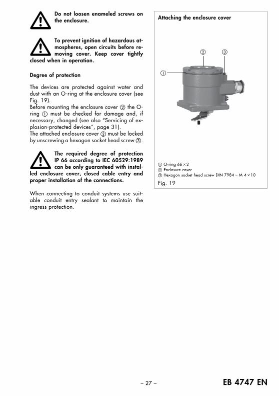
Degree of protection
The devices are protected against water anddust with an O-ring at the enclosure cover (seeFig. 19).Before mounting the enclosure cover � the O-ring � must be checked for damage and, ifnecessary, changed (see also “Servicing of ex-plosion-protected devices“, page 31).The attached enclosure cover � must be lockedby unscrewing a hexagon socket head screw �.
The required degree of protection IP 66 according to IEC 60529:1989can be only guaranteed with instal-
led enclosure cover, closed cable entry andproper installation of the connections.
When connecting to conduit systems use suit-able conduit entry sealant to maintain theingress protection.
�
�
� �
Fig. 19
Attaching the enclosure cover
� O-ring 66 �2� Enclosure cover � Hexagon socket head screw DIN 7984 – M 4 �10
��
EB 4747 EN – 28 –
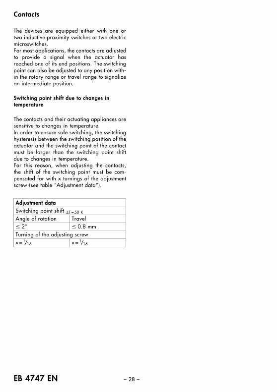
Contacts
The devices are equipped either with one ortwo inductive proximity switches or two electricmicroswitches.For most applications, the contacts are adjustedto provide a signal when the actuator hasreached one of its end positions. The switchingpoint can also be adjusted to any position with-in the rotary range or travel range to signalizean intermediate position.
Switching point shift due to changes in temperature
The contacts and their actuating appliances aresensitive to changes in temperature.In order to ensure safe switching, the switchinghysteresis between the switching position of theactuator and the switching point of the contactmust be larger than the switching point shiftdue to changes in temperature.For this reason, when adjusting the contacts,the shift of the switching point must be com-pensated for with x turnings of the adjustmentscrew (see table “Adjustment data“).
Adjustment dataSwitching point shift �T = 50 K
Angle of rotation Travel� 2° � 0.8 mmTurning of the adjusting screwx = 1/16 x = 1/16
– 29 – EB 4747 EN
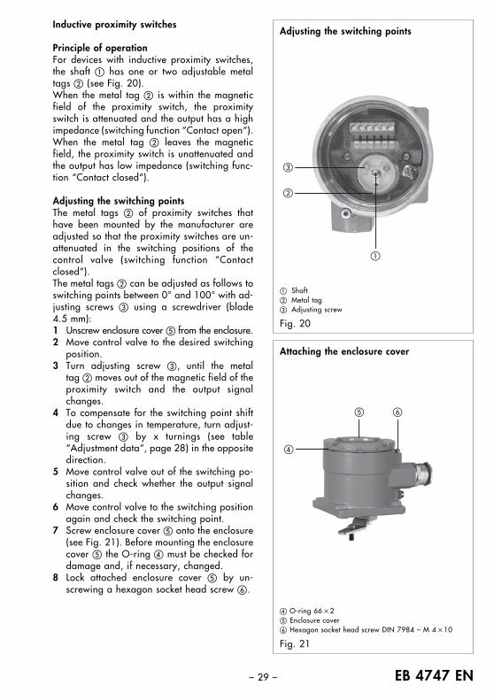
Inductive proximity switches
Principle of operationFor devices with inductive proximity switches,the shaft � has one or two adjustable metaltags � (see Fig. 20).When the metal tag � is within the magneticfield of the proximity switch, the proximityswitch is attenuated and the output has a highimpedance (switching function “Contact open“).When the metal tag � leaves the magneticfield, the proximity switch is unattenuated andthe output has low impedance (switching func-tion “Contact closed“).
Adjusting the switching pointsThe metal tags � of proximity switches thathave been mounted by the manufacturer areadjusted so that the proximity switches are un-attenuated in the switching positions of thecontrol valve (switching function “Contactclosed“).The metal tags � can be adjusted as follows toswitching points between 0° and 100° with ad-justing screws � using a screwdriver (blade4.5 mm):1 Unscrew enclosure cover � from the enclosure.2 Move control valve to the desired switching
position.3 Turn adjusting screw �, until the metal
tag � moves out of the magnetic field of theproximity switch and the output signalchanges.
4 To compensate for the switching point shiftdue to changes in temperature, turn adjust-ing screw � by x turnings (see table“Adjustment data“, page 28) in the oppositedirection.
5 Move control valve out of the switching po-sition and check whether the output signalchanges.
6 Move control valve to the switching positionagain and check the switching point.
7 Screw enclosure cover � onto the enclosure(see Fig. 21). Before mounting the enclosurecover � the O-ring � must be checked fordamage and, if necessary, changed.
8 Lock attached enclosure cover � by un-screwing a hexagon socket head screw �.
�
�
�
Adjusting the switching points
Fig. 20
� Shaft� Metal tag� Adjusting screw
�
� �
Fig. 21
Attaching the enclosure cover
� O-ring 66 �2� Enclosure cover� Hexagon socket head screw DIN 7984 – M 4 �10
EB 4747 EN – 30 –
�
�
�
Adjusting the switching points
Fig. 22
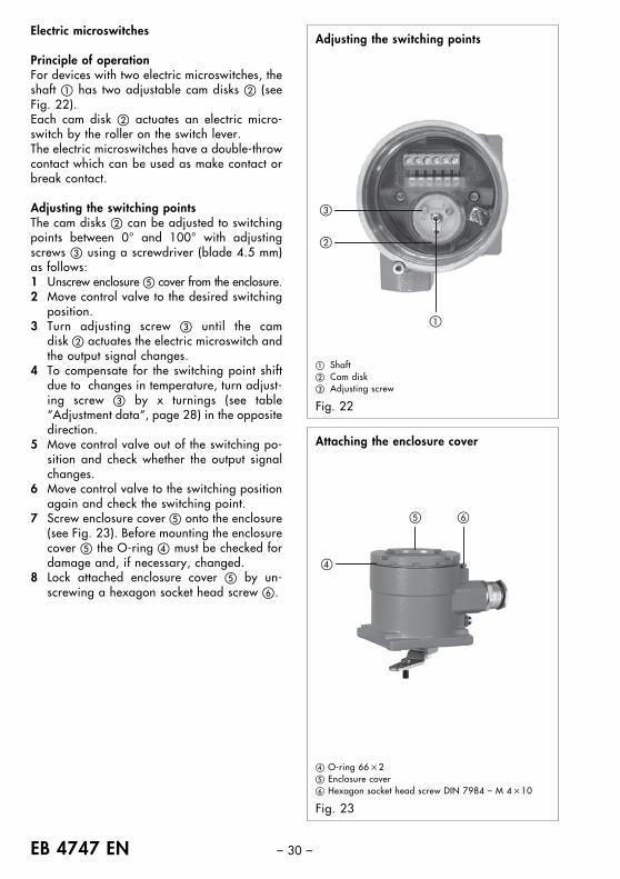
Electric microswitches
Principle of operationFor devices with two electric microswitches, theshaft � has two adjustable cam disks � (seeFig. 22).Each cam disk � actuates an electric micro-switch by the roller on the switch lever.The electric microswitches have a double-throwcontact which can be used as make contact orbreak contact.
Adjusting the switching pointsThe cam disks � can be adjusted to switchingpoints between 0° and 100° with adjustingscrews � using a screwdriver (blade 4.5 mm)as follows:1 Unscrew enclosure � cover from the enclosure.2 Move control valve to the desired switching
position.3 Turn adjusting screw � until the cam
disk � actuates the electric microswitch andthe output signal changes.
4 To compensate for the switching point shiftdue to changes in temperature, turn adjust-ing screw � by x turnings (see table“Adjustment data“, page 28) in the oppositedirection.
5 Move control valve out of the switching po-sition and check whether the output signalchanges.
6 Move control valve to the switching positionagain and check the switching point.
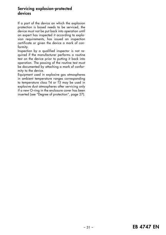
7 Screw enclosure cover � onto the enclosure(see Fig. 23). Before mounting the enclosurecover � the O-ring � must be checked fordamage and, if necessary, changed.
8 Lock attached enclosure cover � by un-screwing a hexagon socket head screw �.
� Shaft� Cam disk� Adjusting screw
�
� �
Fig. 23
Attaching the enclosure cover
� O-ring 66 �2� Enclosure cover� Hexagon socket head screw DIN 7984 – M 4 �10
– 31 – EB 4747 EN
Servicing explosion-protecteddevices
If a part of the device on which the explosionprotection is based needs to be serviced, thedevice must not be put back into operation untilan expert has inspected it according to explo-sion requirements, has issued an inspectioncertificate or given the device a mark of con-formity.Inspection by a qualified inspector is not re-quired if the manufacturer performs a routinetest on the device prior to putting it back intooperation. The passing of the routine test mustbe documented by attaching a mark of confor-mity to the device.Equipment used in explosive gas atmospheresin ambient temperature ranges correspondingto temperature class T4 or T5 may be used inexplosive dust atmospheres after servicing onlyif a new O-ring in the enclosure cover has beeninserted (see “Degree of protection“, page 27).
EB 4747 EN – 32 –
Certification
– 33 – EB 4747 EN
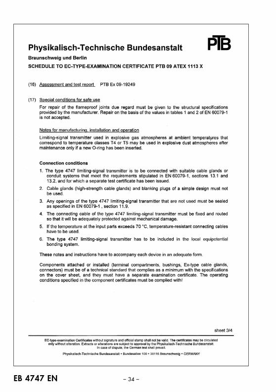
EB 4747 EN – 34 –
– 35 – EB 4747 EN
EB 4747 EN – 36 –
– 37 – EB 4747 EN

EB 4747 EN – 38 –

– 39 – EB 4747 EN

(Specifications subject to change without notice.)
SAMSOMATIC GMBH
A member of the SAMSON GROUP 2012
-05
· EB
474
7 EN
Weismüllerstraße 20 – 2260314 Frankfurt am Main · Germany
Phone: �49 69 4009-0Fax: �49 69 4009-1644E-mail: [email protected]: http://www.samsomatic.de