limited warranty cr grundfos pump cr iom...
TRANSCRIPT

Low-Maintenance Multi-StageCentrifugal Pumps
LIMITED WARRANTY
Please leave these instructions with the pump for future reference.
Installation andOperating Instructions
Products manufactured by (GRUNDFOS) GRUNDFOS PUMPS CORPORATION arewarranted to the original user only to be free of defects in material and workmanshipfor a period of 18 months from date of installation, but not more than 24 months fromdate of manufacture. GRUNDFOS' liability under this warranty shall be limited torepairing or replacing at GRUNDFOS' option, without charge, F.O.B. GRUNDFOS'factory or authorized service station, any product of GRUNDFOS' manufacture.GRUNDFOS will not be liable for any costs of removal, installation, transportation, orany other charges which may arise in connection with a warranty claim. Products whichare sold but not manufactured by GRUNDFOS are subject to the warranty provided bythe manufacturer of said products and not by GRUNDFOS' warranty. GRUNDFOS willnot be liable for damage or wear to products caused by abnormal operating conditions,accident, abuse, misuse, unauthorized alteration or repair, or if the product was notinstalled in accordance with GRUNDFOS' printed installation and operating instructions.
To obtain service under this warranty, the defective product must be returned to thedistributor or dealer of GRUNDFOS' products from which it was purchased together withproof of purchase and installation date, failure date, and supporting installation data.Unless otherwise provided, the distributor or dealer will contact GRUNDFOS or anauthorized service station for instructions. Any defective product to be returned toGRUNDFOS or a service station must be sent freight prepaid; documentation supportingthe warranty claim and/or a Return Material Authorization must be included if soinstructed.
GRUNDFOS WILL NOT BE LIABLE FOR ANY INCIDENTAL OR CONSEQUENTIALDAMAGES, LOSSES, OR EXPENSES ARISING FROM INSTALLATION, USE, ORANY OTHER CAUSES. THERE ARE NO EXPRESS OR IMPLIED WARRANTIES,INCLUDING MERCHANTABILITY OR FITNESS FOR A PARTICULAR PURPOSE,WHICH EXTEND BEYOND THOSE WARRANTIES DESCRIBED OR REFERRED TOABOVE.
Some jurisdictions do not allow the exclusion or limitation of incidental or consequentialdamages and some jurisdictions do not allow limitations on how long implied warrantiesmay last. Therefore, the above limitations or exclusions may not apply to you. Thiswarranty gives you specific legal rights and you may also have other rights which varyfrom jurisdiction to jurisdiction.
LCP-TL-003 Rev. 8/00PRINTED IN U.S.A.
Cool Top™ is a trademark of Grundfos Pumps Corporation.Graflon® is a registered trademark of Morganite.Teflon® is a registered trademark of DuPont.
NOTES:
CR

SAFETY SAFETY SAFETY SAFETY SAFETY WWWWWARNINGARNINGARNINGARNINGARNING
Electrical Electrical Electrical Electrical Electrical WWWWWorororororkkkkkAll electrical work should be performed by a qualified electrician in accordance withthe latest edition of the National Electrical Code, local codes and regulations.
ShocShocShocShocShock Hazark Hazark Hazark Hazark HazardddddA faulty motor or wiring can cause electrical shock that could be fatal, whether toucheddirectly or conducted through standing water. For this reason, proper grounding of thepump to the power supply's grounding terminal is required for safe installation andoperation.
In all installations, the above-ground metal plumbing should be connected to thepower supply ground as described in Article 250-80 of the National Electrical Code.
PrPrPrPrPre-Installae-Installae-Installae-Installae-Installation Chection Chection Chection Chection Checklistklistklistklistklist
1.1.1.1.1. ConfirConfirConfirConfirConfirm m m m m YYYYYou Haou Haou Haou Haou Havvvvve the Right Pumpe the Right Pumpe the Right Pumpe the Right Pumpe the Right PumpRead the pump nameplate to make sure it is the one you ordered.
Page 2
Type of PumpA = Standard pumpE = Ejector pumpSF = High pressure pump without stayboltsS = Pump without stayboltsU = NEMA pumpH = Horizontal pump with electric motor and end-
suction baseR = Horizontal construction with bearing bracketF = Cool Top™ high temperature model
Physical ChangesB = Oversized motorC = Changed point of connectionI = Changed pressure classP = Undersized motor (1 flange size smaller)T = Oversized motor (2 flange sizes larger)X = Special productJ = CRE pumpN = CRE pump with transducerD = Intensifier tank for double seal
Code for MaterialsA = Standard materialsG = Stainless steel parts in 316 SS or similar materialI = Nonstainless parts converted to SSK = Intermediate bearings are bronzeX = Special productZ = Pumps of bronze, components of cast bronzeJ = Shaft or sleeve made of 316 SSGI = Baseplate and flanges are 316 SS or similar materialR = Shaft or sleeve made of 904L SST = Silicon Carbide intermediate bearing/Teflon® sealD = Graflon® bearing
Code for Rubber Parts in Pump(CR32, 45, 64, & 90 only)E = EPDMV = FKMP = NBR (Nitrile)T = PTFE wound around FKMK = Kalrez
Material of Secondary Seal and otherParts made of Plastic/RubberE = EPDMV = FKMP = NBR (Nitrile)S = Q (Silicone rubber)T = PTFE (Teflon®)K = KalrezX = Special productM = PTFE wound around FKM
Material of Stationary RingA = Carbon, metal impregnatedB = Carbon, plastic impregnatedC = Other types of carbonS = Chromium steelU = Tungsten carbideQ = Silicon carbideV = Aluminum oxideX = Other types of ceramicsH = Carbon with imbedded Tungsten Carbide (Hybrid)
Material of Rotating RingA = Carbon, metal impregnatedB = Carbon, plastic impregnatedC = Other types of carbonS = Chromium steelU = Tungsten carbideQ = Silicon carbideV = Aluminum oxideX = Other types of ceramics
Product Number
Centrifugal pump
"N" if all parts in contact with water are 316 stainless steel"T" if all parts in contact with water are Titanium"E" if a Grundfos MGE or MLE VFD motor is attached"X" if all parts in contact with water are 304 and 316 stainless steel
Nominal flow rate in m /hr (multiply by 5 to get GPM)
No. of stages CR32, 45, 64, 90No. of stages x 10 CR2, 4, 8, 16
No. of impellers (used only if pump has fewer impellers than chambers)
No. of reduced diameter impellers (CR32, 45, 64, 90 only)
CR 4 - 20 /1 -1 U - G - A - E - BUBE
A 12345678 P1 98 12
Designated model(e.g. A, B, C, D)
Production Company
Last two digits of year of production
Production week number
Page 3
3
Code for Type of Pump or Physical Changes
Type of Shaft SealA = O-ring seal with fixed seal driverB = Rubber bellows sealC = O-ring seal with a spring working as a driverD = Balanced sealG = Bellows seal with reduced diameter stationary ringM = Metal bellows sealP = Double shaft seal (Tandem)Q = Quench seal (with flushing)R = O-ring seal with reduced diameter stationary ringS = Shaft sealX = MiscellaneousO = Double shaft seal (back to back)H = Balanced seal, cartridgeE = Cartridge with o-ringF = Cartridge with rubber bellows
Code for Pipe ConnectionA = Oval flangeB = NPT threadC = Clamp connectionF = DIN flangeG = ANSI flangeJ = JIS flange
M = Changed flange connectionN = Changed connection diameterO = External threadP = Victaulic couplingW = Internal threadFGJ = DIN, ANSI and JIS flanges combined into one base

50 HZ 60 HZPUMP TYPE MODELS MAX. PSI (BARS) MODELS MAX. PSI (BARS)
CR2/CRN2 20 90 (6) 20 to 60 145/(10)30 to 110 145 (10) 70 to 180 220/(15)130 to 260 220 (15)
CR4/CRN4 20/1 to 20 90 (6) 20/1 to 20 90/(6)30 to 100 145 (10) 30 to 80/7 145/(10)30 to 100 220 (15) 80 to 160/14 220/(15)
CR8/CRN8 20/1 to 60 90 (6) 20/1 to 40 90/(6)80 to 200 145 (10) 50 to 160 145/(10)
CR16/CRN16 30/2 to 30 90 (6) 30/2 to 30 90/(6)40 to 160 145 (10) 40 to 120 145/(10)
CRN–SF ALL 73/(5) ALL 73/(5)365/(25) 365/(25)
CR32/CRN32 1-1 to 2-1 45 (3) 1-1 to 1 45 (3)2 to 4 60 (4) 2-1 to 2 60 (4)5 to 10 145 (10) 3 to 5 145 (10)11 to 14 220 (15) 6 to 11-2 220 (15)
CR45/CRN45 1-1 45 (3) 1-1 to 1 60 (4)1 to 2 60 (4) 2-2 to 3 145 (10)
3-2 to 5-1 145 (10) 4-2 to 7-2 220 (15)6 to 10 220 (16)
CR64/CRN64 1-1 to 2-2 60 (4) 1-1 60 (4)2-1 to 3 145 (10) 1 to 2-1 145 (10)
4-1 to 7-1 220 (15) 2 to 4-1 220 (15)
CR90 1-1 to 1 60 (4) 1-1 to 1 145 (10)2-2 to 3-2 145 (10) 2-2 to 4-1 220 (15)3-1 to 6 220 (15)
PrPrPrPrPre-Installae-Installae-Installae-Installae-Installation Chection Chection Chection Chection Checklistklistklistklistklist
Page 5
Maximum Working Pressures:(The following pressures are given for fluids at 250°F [194°F for CRN–SF].Consult Grundfos for other working conditions.)
2.2.2.2.2. Check the Condition of the PumpCheck the Condition of the PumpCheck the Condition of the PumpCheck the Condition of the PumpCheck the Condition of the PumpThe shipping carton your pump came in is specially designed around your pump duringproduction to prevent damage. As a precaution, the pump should remain in the carton untilyou are ready to install it. Examine the pump for any damage that may have occurred duringshipping. Examine any other parts of the shipment as well for any visible damage.
If the pump is shipped as a complete unit (motor attached to pump end), the positionof the coupling (that connects the pump shaft to the motor shaft) is set at factoryspecifications. No adjustment is required. If the unit is delivered as a pump end only,follow the adjustment procedures on pages 15-16.
Pump without Motor (CR(N)32, CR(N)45, CR(N)64 & CR90 Only): If you purchased apump without a motor, you must install the seal. The seal is protected in its own sub boxingwithin the pump packaging crate. To protect the shaft and bearings during shipment, a shaftholder protective device is used. This device must be removed prior to installation of theseal. Read the seal installation instructions which are included in the pump package.
3.3.3.3.3. VVVVVerify Electrical Rerify Electrical Rerify Electrical Rerify Electrical Rerify Electrical RequirequirequirequirequirementsementsementsementsementsVerification of the electrical supply should be made to be certain the voltage, phase andfrequency match that of the pump motor. The proper operating voltage and other electricalinformation can be found on the motor nameplate. These motors are designed to run on±10% of the nameplate-rated voltage. For dual-voltage motors, the motor should beinternally connected to operate on the voltage closest to the 10% rating, i.e., a 208 voltagemotor wired per the 208 volt connection diagram. The wiring connection diagram can befound on either a plate attached to the motor or on a diagram inside the terminal box cover.If voltage variations are larger than ±10%, do not operate the pump.
4.4.4.4.4. Is the Is the Is the Is the Is the AAAAApplicapplicapplicapplicapplication Cortion Cortion Cortion Cortion Corrrrrrect fect fect fect fect for or or or or TTTTThis Pump?his Pump?his Pump?his Pump?his Pump?Compare the pump's nameplate data or its performance curve with the application in whichyou plan to install it. Will it perform the way you want it to perform? Also, make sure theapplication falls within the following limits:
Type Designed to pump...
CR Hot and chilled water, boiler feed, condensate return, glycols andsolar thermal fluids.
CRN/CRX Deionized, demineralized and distilled water. Brackish water and otherliquids unsuitable for contact with iron or copper alloys. (Consultmanufacturer for specific liquid compatibilities.)
CRN–SF High pressure washdown, reverse osmosis, or other high pressureapplications.
CRT Salt water, chloride based fluids and fluids approved for titanium.
Operating ConditionsFluid Temperatures:
CR2, CR4, CR8, CR16 5° to 250°F (-15° to 121°C)CRN–SF 5° to 194°F (-15° to 90°C)
5° to 355°F (-15° to 180°C) Cool Top™ models
CR(N)32, CR(N)45, CR(N)64, CR90 -22° to 250°F* (-30° to 120°C)-22° to 355°F** (-30° to 180°C) Cool Top™ models
All motors are designed for continuous duty in 104°F (40°C) ambient air conditions. Forhigher ambient temperature conditions consult Grundfos.
* EUBE Shaft Seals are recommended for temperatures above 200°F. Pumps with hybrid shaftseals can only operate up to 200°F (90°C). Pumps with EUUE shaft seals can be operated downto -40°F (-40°C).
** With optional Cool Top™ high temperature model.
PrPrPrPrPre-Installae-Installae-Installae-Installae-Installation Chection Chection Chection Chection Checklistklistklistklistklist
Page 4
Minimum Inlet Pressures:All CR and CRN pumps NPSHR + 2 feetCRN–SF pumps 29 psi (2 Bar)
Maximum Inlet Pressures:
50 HZ 60 HZPUMP TYPE MODELS MAX. PSI (BARS) MODELS MAX. PSI (BARS)
CR2/CRN2 20 to 150 230 (16) 20 to 100 230/(16)180 to 260 300 (20) 120 to 180 300/(20)
CR4/CRN4 20/1 to 160 230 (16) 20/1 to 100 230/(16)190 to 220 300 (20) 120 to 160/14 300/(20)
CR8/CRN8 20/1 to 120 230 (16) 20/1 to 80 230/(16)140 to 200 330 (23) 100 to 160 330/(23)
CR16/CRN16 30/2 to 80 230 (16) 30/2 to 80 230/(16)100 to 160 330 (23) 100 to 120 330/(23)
CR32/CRN32 1-1 to 7 230 (16) 1-1 to 5 230 (16)8 to 12 365 (25) 6 to 8 365 (25)13 to 14 435 (30) 9-2 to 11-2 435 (30)
CR45/CRN45 1-1 to 6 230 (16) 1-1 to 4-2 230 (16)7 to 9-2 365 (25) 4-1 to 6 365 (25)
10 435 (30) 7-2 435 (30)
CR64 to CRN64 1-1 to 5 230 (16) 1-1 to 3 230 (16)6-2 to 7-1 365 (25) 4-2 to 4 365 (25)
CR90 1-1 to 5 230 (16) 1-1 to 3 230 (16)6-2 to 6 365 (25) 4-2 to 4-1 365 (25)
CRN-SF ALL 653 (45) ALL 653 (45)
(while pump is off orduring start-up)
(during operation)

CR(N)45 & CR(N)64
(4) 9/16" HOLES(14mm)
CR8-CR16, CRN8-CRN16
(4) 1/2" HOLES(13mm)
CR2-CR4
CRN2-CRN4
InstallaInstallaInstallaInstallaInstallation Prtion Prtion Prtion Prtion ProceduroceduroceduroceduroceduresesesesesInstallaInstallaInstallaInstallaInstallation Chection Chection Chection Chection Checklistklistklistklistklist
(whil
Suction Lift*Flooded Suction
Figure 1: Bolt Hole Centers
Select Pump LocaSelect Pump LocaSelect Pump LocaSelect Pump LocaSelect Pump LocationtiontiontiontionThe pump should be located in a dry, well-ventilatedarea which is not subject to freezing or extreme variationin temperature. Care must be taken to ensure the pumpis mounted at least 6 inches (150 mm) clear of anyobstruction or hot surfaces. The motor requires anadequate air supply to prevent overheating and adequatevertical space to remove the motor for repair. For opensystems requiring suction lift the pump should be locatedas close to the water source as possible to reduce pipinglosses.
FFFFFoundaoundaoundaoundaoundationtiontiontiontionConcrete or similar foundation material should be usedto provide a secure, stable mounting base for the pump.Bolt hole center line dimensions for the various pumptypes are given in Figure 1. Secure the pump to thefoundation using all four bolts and shim pump base toassure the pump is vertical and all four pads on the baseare properly supported. Uneven surfaces can result inpump base breakage when mounting bolts are tightened.
The pump can be installed vertically or horizontally, seedrawing below. Ensure that an adequate supply of coolair reaches the motor cooling fan. The motor must neverfall below the horizontal plane.
Arrows on the pump base show the direction of flow ofliquid through the pump.
To minimize possible noise from the pump, it is advisableto fit expansion joints either side of the pump and anti-vibration mountings between the foundation and thepump.
Isolating valves should be fitted either side of the pumpto avoid draining the system if the pump needs to becleaned, repaired or replaced.
PipePipePipePipePipewwwwworororororkkkkk
Minimum Suction Pipe SizesThe following recommended suction pipe sizes are the smallest sizes which shouldbe used with any specific CR pump type. The suction pipe size should be verified witheach installation to ensure good pipe practices are being observed and excess frictionlosses are not encountered. High temperatures may require larger diameter pipes toreduce friction and improve NPHSA.
CR2 ............................... 1" Nominal diameter sch 40 pipeCR4 ............................... 1 1⁄4" Nominal diameter sch 40 pipeCR8 & CR16 ................. 2" Nominal diameter sch 40 pipeCR(N)32 ........................ 2 1⁄2" Nominal diameter sch 40 pipeCR(N)45 ........................ 3" Nominal diameter sch 40 pipeCR(N)64 ........................ 4" Nominal diameter sch 40 pipeCR90 ............................. 4" Nominal diameter sch 40 pipe
Discharge PipingIt is suggested that a check valve and isolation valve be installed in the discharge pipe.Pipe, valves and fittings should be at least the same diameter as the discharge pipeor sized in accordance with good piping practices to reduce excessive fluid velocitiesand pipe friction losses. Pipe, valves and fittings must have a pressure ratingequal to or greater than the maximum system pressure. Before the pump isinstalled it is recommended that the discharge piping be pressure checked to at leastthe maximum pressure the pump is capable of generating or as required by codes orlocal regulations.
Whenever possible, avoid high pressure loss fittings, such as elbows or branch teesdirectly on either side of the pump. The piping should be adequately supported to
Page 7
*CRN–SF pumps cannot be used for suction lift.The suction pipe should have a fitting on it forpriming.
Figure 2
(4) 1/2" HOLES(13mm)
Page 6
(4) 1/2" HOLES(13mm)
CR(N)32
(4) 9/16" HOLES(14mm)
CR90
(4) 9/16" HOLES(14mm)
NOTE: The CR(N) pumps are shipped with covered suctionand discharge. The covers must be removed before the finalpipe flange to pump connections are made.
Suction PipeThe suction pipe should be adequately sized and run as straight and short as possibleto keep friction losses to a minimum (minimum of four pipe diameters straight run priorto the suction flange). Avoid using unnecessary fittings, valves or accessory items.Butterfly or gate valves should only be used in the suction line when it is necessaryto isolate a pump because of a flooded suction condition. This would occur if the watersource is above the pump. See Figures 2 and 3. Flush piping prior to pump installationto remove loose debris.covers must be removed before the final pipe flange to pump connections are made.
Figure 3
3 15
/16"
(100
mm
)
8 1/4" (210mm)
7 1/16" (180mm)
5 3/
4"(1
47m
m)
8 1/4" (210mm)
7 1/16" (180mm)
9 3/4" (246mm)
8 1/2" (215mm)
11 3/4" (298mm)
9 7/16" (240mm)
13 3/4" (348mm)
3 15
/16"
(100
mm
)
5 15
/16"
(150
mm
)
5 1/
8"(1
30m
m)
1 7/
8"(1
99m
m)
7 1/
2"(1
90m
m)
9 7/
8"(2
51m
m)
10 5
/16"
(261
mm
)
7 7/
8"(1
99m
m)
11" (280mm)
13" (331mm)
10 1/2" (266mm)
6 11
/16"
(170
mm
)8
7/8
"(2
26m
m)

InstallaInstallaInstallaInstallaInstallation Prtion Prtion Prtion Prtion Procedurocedurocedurocedurocedureseseseses
For Pump Ends With Bellows SealsOnly (CR 2, 4, 8, 16)Remove shaft seal protectors before installingmotor (see diagram).
Page 8
reduce thermal and mechanical stresses on the pump. Good installation practicerecommends the system be thoroughly cleaned and flushed of all foreign materialsand sediment prior to pump installation. Furthermore, the pump should never beinstalled at the lowest point of the system due to the natural accumulation of dirt andsediment. If there is excessive sediment or suspended particles present, it is adviseda strainer or filter be used. Grundfos recommends that pressure gauges be installedon inlet and discharge flanges or in pipes to check pump and system performance.
Check ValvesA check valve may be required on the discharge side of the pump to prevent thepump's inlet pressure from being exceeded. For example, if a pump with no checkvalve is stopped because there is no demand on the system (all valves are closed),the high system pressure on the discharge side of the pump will "find" its way back tothe inlet of the pump. If the system pressure is greater than the pump's maximum inlet
pressure rating, the limits of the pump will beexceeded and a check valve needs to befitted on the discharge side of the pump toprevent this condition. This is especiallycritical for CRN–SF applications becauseof the very high discharge pressuresinvolved. As a result, most CRN–SFinstallations require a check valve on thedischarge piping.
BypassA bypass should be installed in the dischargepipe if there is any possibility the pump mayoperate against a closed valve in the dischargeline. Flow through the pump is required toensure adequate cooling and lubrication ofthe pump is maintained. See Table A forminimum flow rates. Elbows should be aminimum of 12" from the orifice discharge toprevent erosion.
Temperature RiseIt may sometimes be necessary to stop theflow through a pump during operation. Atshut-off, the power to the pump is transferredto the pumped liquid as head, causing atemperature rise in the liquid.
The result is risk of excess heating of andconsequent damage to the pump. The riskdepends on the temperature of the pumpedliquid and for how long the pump is operatingwithout flow.
NOTE: To avoid problems with waterhammer, fast closing valvesmust not be used in CRN–SF applications.
The table below states the time for 18°F (10°C) temperature rise.
Conditions/ReservationsThe listed times are subject to the following conditions/reservations:
• No exchange of heat with the surroundings
• The pumped liquid is water with a specific heat of 1.0 (4.18 )
• Pump parts (chambers, impellers and shaft) have the same thermalcapacity as water.
• The water in the base and the pump head is not included
These reservations should give sufficient safety margin against excessive temperaturerise.
The maximum temperature must not exceed the pump maximum rating.
InstallaInstallaInstallaInstallaInstallation Prtion Prtion Prtion Prtion Procedurocedurocedurocedurocedureseseseses
PUMP TYPE SECONDS MINUTES
CR2 213 3.6CR4 237 4.0CR8 203 3.4CR16 150 2.5CR32CR45CR64CR90
Page 9
TIME FOR TEMPERATURE RISE OF 18°F
ConsultFactory
Btulb. °F
kJkg°C
TABLE AMinimum Continuous Duty Flow Rates for
CR, CRN, CRNG, CRN–SF, CRT
NippleOrifice
LIQUID TEMPERATURE
CR2/CRN2–SF 1.0 GPM 1.0 GPMCR4/CRN4–SF 2.0 GPM 2.0 GPMCR8/CRN8–SF 4.0 GPM 4.0 GPMCR16/CRN16–SF 8.0 GPM 8.0 GPMCR(N)32 15.0 GPM 33.0 GPMCR(N)45 23.0 GPM 44.0 GPMCR(N)64 35.0 GPM 64.0 GPMCR90 45.0 GPM 88.0 GPM
5°F TO 176°F 176°F TO 355°FPUMP TYPE -15°C TO 80°C 80°C TO 180°C
1. Remove coupling guards.2. Remove coupling halves.3. Remove shaft seal protectors.4. Follow motor replacement instructions on page 15.

StarStarStarStarStarting the Pump the Firting the Pump the Firting the Pump the Firting the Pump the Firting the Pump the First st st st st TimeTimeTimeTimeTimePrimingTo prime the pump in a closed system or an opensystem where the water source is above the pump,close the pump isolation valve(s) and open the primingplug on the pump head. See Figures 5A and 5B.Gradually open the isolation valve in the suction lineuntil a steady stream of airless water runs out thepriming port. Close the plug and securely tighten.Completely open the isolation valves.
In open systems where the water level is below thepump inlet, the suction pipe and pump must be filledand vented of air before starting the pump. Close thedischarge isolation valve and remove the primingplug. Pour water through the priming hole until thesuction pipe and pump are completely filled with water. If the suction pipe does notslope downward from the pump toward the water level, the air must be purged whilebeing filled. Replace the priming plug and securely tighten.
Check the Direction of Rotation1. Switch power off.2. Check to make sure the pump has been filled and vented.3. Remove the coupling guard and rotate the pump shaft by hand to be
certain it turns freely.
OperOperOperOperOperaaaaation and Maintenancetion and Maintenancetion and Maintenancetion and Maintenancetion and Maintenance
Figure 5A CR2 & 4
2. Three-Phase MotorsCR pumps with three-phase motors must be used with the proper size and typeof motor-starter to ensure the motor is protected against damage from low voltage,phase failure, current imbalance and overloads. A properly sized starter withmanual reset and ambient-compensated extra quick trip in all three legs should beused. The overload should be sized and adjusted to the full-load current rating ofthe motor. Under no circumstances should the overloads be set to a highervalue than the full load current shown on the motor nameplate. This will voidthe warranty. Overloads for auto transformers and resistant starters should besized in accordance with the recommendations of the manufacturer. Three phaseMLE motors (CRE-Pumps) require only fuses as a circuit breaker. They do notrequire a motor starter. Check for phase imbalance (worksheet is provided onpages 22 & 23).
NOTE: Standard allowable phase imbalance difference is 5%.
3. CRN–SFThe CRN–SF is typically operated in series with a feed pump. Because themaximum allowable inlet pressure of the CRN–SF increases from 73 psi (whenpump is off and during start-up) to 365 psi (during operation), a control device mustbe used to start the CRN–SF pump one second before the feed pump starts.Similarly, the CRN–SF must stop one second after the feed pump stops.
ElectricalElectricalElectricalElectricalElectrical
Page 11
Grundfos CR pumps are supplied with heavy-duty 2-pole (3450, 3525,or 3550 RPM),ODP or TEFC, NEMA C frame motors selected to our rigid specifications. Motors withother enclosure types and for other voltages and frequencies are available on aspecial-order basis. CRN–SF pumps are supplied with an IEC (metric) type motor witha reverse thrust bearing. If you are replacing the pumping unit, but are using a motorpreviously used on another CRpump, be sure to read the "MotorReplacement" section on pages15-16 for proper adjustment of thecoupling height.
PPPPPosition ofosition ofosition ofosition ofosition ofTTTTTerererererminal Bominal Bominal Bominal Bominal BoxxxxxThe motor terminal box can beturned to any of four positions in90° steps. To rotate the terminalbox, remove the four bolts securingthe motor to the pump but do notremove the shaft coupling; turnthe motor to the desired location;replace and securely tighten thefour bolts. See Figure 4.
WARNINGTHE SAFE OPERATION OF THIS PUMP REQUIRES THAT IT BE GROUNDED INACCORDANCE WITH THE NATIONAL ELECTRICAL CODE AND LOCAL GOVERNINGCODES OR REGULATIONS. CONNECT THE GROUND WIRE TO THE GROUNDINGSCREW IN THE TERMINAL BOX AND THEN TO THE ACCEPTABLE GROUNDINGPOINT.
All electrical work should be performed by a qualified electrician in accordance with thelatest edition of the National Electrical Code, local codes and regulations.
MotorMotorMotorMotorMotor
Motor Terminal Box Positions(Top View)
Discharge
Suction
Terminal Box9:00 Position
Figure 4
ElectricalElectricalElectricalElectricalElectrical
Terminal Box3:00 Position
Terminal Box12:00 Position
StandardTerminal Box6:00 Position
Field WiringField WiringField WiringField WiringField WiringWire sizes should be based on the current carrying properties of a conductor asrequired by the latest edition of the National Electrical Code or local regulations. Directon line (D.O.L.) starting is approved due to the extremely fast run-up time of the motorand the low moment of inertia of pump and motor. If D.O.L. starting is not acceptableand reduced starting current is required, an auto transformer, resistant starter or softstart should be used. It is suggested that a fused disconnect be used for each pumpwhere service and standby pumps are installed.
Motor ProtectionMotor ProtectionMotor ProtectionMotor ProtectionMotor Protection1. Single-Phase Motors:
With the exception of 7 1⁄2 and 10 HP motors which require external protection,single-phase CR pumps are equipped with multi-voltage, squirrel-cage inductionmotors with built-in thermal protection.
Page 10
CR2 & 4
CR8 & 16

Figure 5B CR32, 45, 64 & 90
4. Verify that the electrical connections are inaccordance with the wiring diagram on themotor.
5. Switch the power on and observe thedirection of rotation. When viewed fromthe top, the pump should rotate counter-clockwise (clockwise for CRN–SF).
6. To reverse the direction of rotation, firstswitch OFF the supply power.
7. On three-phase motors, interchange anytwo power leads at the load side of thestarter. On single-phase motors, seeconnection diagram on nameplate.Change wiring as required.
8. Switch on the power and again check forproper motor rotation. Replace thecoupling guard if the rotation is correct.Once rotation has been verified, switch off power again. Do not attemptto reinstall the coupling guards with the motor energized. After guardsare in place the power can be reapplied.
OperOperOperOperOperaaaaation and Maintenancetion and Maintenancetion and Maintenancetion and Maintenancetion and Maintenance
Starting and AdjustingBefore starting the pump, please check:1. Pump is primed.2. Direction of rotation is counter-clockwise when viewed from the top (clockwise
for CRN–SF).3. All piping connections are tight and the pipes are adequately supported.4. Suction line isolation valve is completely opened, if a valve has been installed.5. For initial starting, the isolation valve in the discharge pipe should be closed
and gradually opened after the pump is turned on. Opening this valve too fastmay result in some water hammering in the discharge pipe. Unless used as aflow throttling device, make sure this valve is completely open.
6. Check and record the voltage and amperage of the motor. Adjust the motoroverloads if required.
7. Check and record operating pressures if pressure gauges have been installed.8. Check all controls for proper operation. If pump is controlled by a pressure
switch, check and adjust the cut-in and cut-out pressures. If low-water-levelcontrols are used, be sure the low level switch is properly adjusted so thepump cannot run if the pump should break suction.
Operating ParametersCR multi-stage centrifugal pumps installed in accordance with these instructions andsized for correct performance will operate efficiently and provide years of service. Thepumps are water-lubricated and do not require any external lubrication or inspection.The motors will require periodic lubrication as noted in the following MaintenanceSection.
Ventplug
Loosen center plugto vent pump
Do not start the pump beforepriming or venting the pump.Never operate the pump dry.
NOTE: Motors should not be run unloaded or uncoupled from the pump at anytime; damage to the motor bearings will occur.
Page 12
DischargeSuction
Priming Plug(opposite side)
Vent Plug
OperOperOperOperOperaaaaation and Maintenancetion and Maintenancetion and Maintenancetion and Maintenancetion and Maintenance
Under no circumstances should the pump be operated for any prolongedperiods of time without flow through the pump. This can result in motor and pumpdamage due to overheating. A properly sized relief valve should be installed to allowsufficient water to circulate through the pump to provide adequate cooling andlubricaton of the pump bearings and seals.
Pump cycling — Pump cycling should be checked to ensure the pump is not startingmore than: 20 times per hour on 1/2 to 5 HP models
15 times per hour on 7 1/2 to 15 HP models10 times per hour on 20 to 60 HP models
Rapid cycling is a major cause of premature motor failure due to increased heat build-up in the motor. If necessary, adjust controls to reduce the frequency of starts andstops.
Boiler-feed installations — If the pump is being used as a boiler-feed pump, makesure the pump is capable of supplying sufficient water throughout its entire evaporationand pressure ranges. Where modulating control valves are used, a bypass aroundthe pump must be installed to ensure pump lubrication (see "Minimum ContinuousDuty Flow Rates").
MaintenanceMaintenanceMaintenanceMaintenanceMaintenanceFreeze ProtectionIf the pump is installed in an area where freezing could occur, the pump and systemshould be drained during freezing temperatures to avoid damage. To drain the pump,close the isolation valves, remove the priming plug and drain plug at the base of thepump. Do not replace the plugs until the pump is to be used again. Always replacethe drain plug with the original or exact replacement. Do not replace with a standardplug. Internal recirculation will occur, reducing the output pressure and flow.
Motor InspectionInspect the motor at regular intervals, approximately every 500 hours of operation orevery three months, whichever occurs first. Keep the motor clean and the ventilationopenings clear. The following steps should be performed at each inspection:
1. Check that the motor is clean. Check that the interior and exterior of themotor is free of dirt, oil, grease, water, etc. Oily vapor, paper pulp, textilelint, etc. can accumulate and block motor ventilation. If the motor is notproperly ventilated, overheating can occur and cause early motor failure.
2. Use an Ohmmeter ("Megger") periodically to ensure that the integrity ofthe winding insulation has been maintained. Record the Ohmmeterreadings. Immediately investigate any significant drop in insulationresistance.
3. Check all electrical connectors to be sure that they are tight.
Motor LubricationElectric motors are pre-lubricated at the factory and do not require additionallubrication at start-up. Motors without external grease fittings have sealed bearings
WARNINGDO NOT TOUCH ELECTRICAL CONNECTIONS BEFORE YOU FIRST ENSURE THATPOWER HAS BEEN DISCONNECTED. ELECTRICAL SHOCK CAN CAUSE SERIOUSOR FATAL INJURY. ONLY QUALIFIED PERSONNEL SHOULD ATTEMPT THEINSTALLATION, OPERATION AND MAINTENANCE OF THIS EQUIPMENT.
Page 13
REMINDER
Drain Plugs (G 1⁄2 A)with 1⁄4" NPT gauge/sensor taps

• Note the clearance belowthe coupling
• Raise the coupling higher, asfar as it will go
• Lower it halfway backdown(1/2 the distance youjust raised it)
• Tighten screwsM6...10ft lbs (13Nm)M8...23ft lbs (31Nm)M10...46ft lbs (62Nm)
Regular CheckupsAt regular intervals depending on the conditions and time of operation, the followingchecks should be made:
1. Pump meets required performance and is operating smoothly and quietly.2. There are no leaks, particularly at the shaft seal.3. The motor is not overheating.4. Remove and clean all strainers or filters in the system.5. Verify the tripping of the motor overload protection.6. Check the operation of all controls. Check unit control cycling twice
and adjust, if necessary.7. If the pump is not operated for unusually long periods, the unit should
be maintained in accordance with these instructions. In addition, ifthe pump is not drained, the pump shaft should be manually rotatedor run for short periods of time at monthly intervals.
If the pump fails to operate or there is a loss of performance, refer to the TroubleShooting section on pages 17-20.
OperOperOperOperOperaaaaation and Maintenancetion and Maintenancetion and Maintenancetion and Maintenancetion and Maintenance
Page 15
Motor ReplacementIf the motor is damaged due to bearing failure, burning or electrical failure, the followinginstructions detail how to remove the motor for replacement. It must be emphasizedthat motors used on CR pumps are specifically selected to our rigid specifications.Replacement motors must be of the same frame size, should be equipped with thesame or better bearings and have the same service factor. Failure to follow theserecommendations may result in prematuremotor failure.
Disassembly1. Turn off and lock out power supply. The
power supply wiring can now be safelydisconnected from the motor wires.
2. Remove the coupling guards.3. Using the proper metric Allen wrench,
loosen the four cap screws in thecoupling. Completely remove couplinghalves. On CR2-CR60s, the shaft pincan be left in the pump shaft. CR(N)32,45, 64 and CR90s do not have a shaftpin.
4. With the correct size wrench, loosen andremove the four bolts which hold themotor to the pump end.
5. Lift the motor straight up until the shafthas cleared the motor stool.
Assembly1. Remove key from motor shaft, if present,
and discard.2. Thoroughly clean the surfaces of the motor and pump end mounting flanges.
The motor and shaft must be clean of all oil/grease and other contaminantswhere the coupling attaches. Set the motor on the pump end.
3. Place the terminal box in the desiredposition by rotating the motor.
OperOperOperOperOperaaaaation and Maintenancetion and Maintenancetion and Maintenancetion and Maintenancetion and Maintenance
Approved Types of Grease
AmbientSeverity Temperature Atmospheric
of Service (Maximum) ContaminationStandard 104°F (40°C) Clean, little corrosionSevere 122°F (50°C) Moderate dirt, corrosionExtreme >122°F (50°C) Severe dirt, abrasive
or Class H dust, corrosioninsulation
Page 14
that cannot be re-lubricated. Motors with grease fittings should only be lubricated withapproved types of grease. Do not over grease the bearings. Over greasing willcause increased bearing heat and can result in bearing/motor failure. Do not mixpetroleum grease and silicon grease in motor bearings.
Bearing grease will lose its lubricating ability over time, not suddenly. The lubricatingability of a grease (over time) depends primarily on the type of grease, the size of thebearings, the speed at which the bearings operate and the severity of the operatingconditions. Good results can be obtained if the following recommendations are usedin your maintenance program.
Service Conditions*
Lubrication Schedule*
Procedure
1. Clean all grease fittings. If the motor does not have grease fittings, thebearing is sealed and cannot be greased externally.
2. If the motor is equipped with a grease outlet plug, remove it. This willallow the old grease to be displaced by the new grease.
3. If the motor is stopped, add the recommended amount of grease. If themotor is to be greased while running, a slightly greater quantity of greasewill have to be added.
Add grease SLOWLY until new grease appears at the shaft hole in theendplate or grease outlet plug. Never add more than 11/2 times theamount of grease shown in the lubrication schedule.NOTE: If new grease does not appear at the shaft hole or greaseoutlet plug, the outlet passage may be blocked. At the next serviceinterval the bearings must be repacked.
4. For motors equipped with a grease outlet plug, let the motor run for 20minutes before replacing the plug.
CAUTIONTO AVOID DAMAGE TO MOTOR BEARINGS, GREASE MUST BE KEPT FREE OF DIRT.FOR AN EXTREMELY DIRTY ENVIRONMENT, CONTACT YOUR BALDOR DISTRIBUTOROR AN AUTHORIZED BALDOR SERVICE CENTER FOR ADDITIONAL INFORMATION.
Figure 6: CR(N) 2, 4, 8 & 16
Standard Severe Extreme Weight of Volume ofNEMA/(IEC) Service Service Service Grease to Add Grease to AddFrame Size Interval Interval Interval Oz./(Grams) In3/(Teaspoons)
Up through 210 (132) 5500 hrs. 2750 hrs. 550 hrs. 0.30 (8.4) 0.6 (2)Over 210 through 280 (180) 3600 hrs. 1800 hrs. 360 hrs. 0.61 (17.4)* 1.2 (3.9)**Over 280 up through 360 (225) 2200 hrs. 1100 hrs. 220 hrs. 0.81 (23.1)* 1.5 (5.2)**Over 360 (225) 2200 hrs. 1100 hrs. 220 hrs. 2.12 (60.0)* 4.1 (13.4)** *Applies to optional bearing flange also.**The grease outlet plug MUST be removed before adding new grease.
Shell Dolium RChevron SRI#2
Or compatible equivalenttype of grease

OperOperOperOperOperaaaaation and Maintenancetion and Maintenancetion and Maintenancetion and Maintenancetion and Maintenance PPPPParararararts Liststs Liststs Liststs Liststs Lists,,,,, Kits Kits Kits Kits Kits,,,,, and and and and and AccessoriesAccessoriesAccessoriesAccessoriesAccessories
PPPPParararararts Listts Listts Listts Listts ListFor each CR pump model Grundfos offers an extensive Parts List and diagram ofparts used in that pump and is recommended to have on hand for future maintenance.In addition, the listings also provide information about prepackaged Service Kits forthose pump components most likely to exhibit wear over time, as well as the completeImpeller Stack needed to replace the "guts" of each model. These Parts Lists areavailable separately from the Grundfos literature warehouse or as a set with extensiveservice instructions in the Grundfos CR Service Manuals (for a small charge).
SparSparSparSparSpare Pe Pe Pe Pe PararararartststststsGrundfos offers an extensive list of spare parts. For a current list of these parts, referto: "All Product Spare Parts/Service Kits" Price List, Form # L-SK-SL-002.
TopView
Prepackagedimpeller stacksready forimmediateinstallation
TheStack
PrepackagedFlange Kits
Coupling Min. TorqueBolt Size Specifications
M6 ............. 10 ft-lbs. M8 ............. 23 ft-lbs. M10 ........... 46 ft-lbs.
Torque Specifications4. Insert the mounting bolts, then diagonally andevenly tighten. For 3⁄8" Ø bolts torque to 10 ft.-lbs.and for 1⁄2" Ø bolts torque to 23 ft.-lbs.
5. CR2, 4, 8 & 16:Reinstall coupling halves. Make sure the shaft pinis located in the pump shaft. Put the cap screwsloosely back into the couplinghalves. Using a larger screwdriver,raise the pump shaft by placing thetip of the screwdriver under thecoupling and carefully elevating thecoupling toits highest point (see Figure 6). Note: Theshaft can only be raised approximately 0.20
inches (5mm). Nowlower the shaft halfwayback down the distance you just raised it and tightenthe coupling screws (finger tight) while keeping thecoupling separation equal on both sides. When thescrews are tight enough to keep the couplings inplace, then torque the screws evenly in a criss-crosspattern.
CR(N) 32, 45, 64 & CR90:Place the plastic adjustment fork under the cartridgeseal collar (see Figure 7). Fit the coupling on the shaftso that the top of the pump shaft is flush with the bottomof the clearance chamber in the coupling (see Figure 8).
Lubricate the coupling screws with an anti-seize and lubricating compound. Tightenthe coupling screws (finger tight) while keeping the coupling separation equal on bothsides. When the screws are tight enough to keep the couplings in place, then torquethe screws evenly in a crisscross pattern.
Torque coupling screws to 59 ft.-lbs. Remove the adjustment fork from underthe cartridge seal collar and replace it to the storage location (see Figure 9).
Page 16 Page 17
Figure 7
Figure 8
Figure 96. Check to see that the gaps between the
coupling halves are equal. Loosen and re-adjust, if necessary.
7. Be certain the pump shaft can be rotated byhand. If the shaft cannot be rotated or it binds,disassemble and check for misalignment.
8. Replace the two coupling guards.9. Prime the pump.
10. Follow the wiring diagram on the motor label forthe correct motor wiring combination whichmatches your supply voltage. Once this hasbeen confirmed, reconnect the power supplywiring to the motor. The motor is now ready tohave the power turned back on.
11. Check the direction of rotation, this must be left to right (counter-clockwise)when looking directly at the coupling.
12. Shut off the power, then re-install the coupling guards. After the couplingguards have been installed the power can be turned back on.
CORRECT
INCORRECT
NOTE: To avoiddamaging the couplinghalves, ensure that noportion of the keywayon the motor shaft lieswithin the gap betweenthe two coupling halves.
FlangeKits
DiaDiaDiaDiaDiagnosing Specific Prgnosing Specific Prgnosing Specific Prgnosing Specific Prgnosing Specific Proboboboboblemslemslemslemslems
Problem Possible Cause Remedy
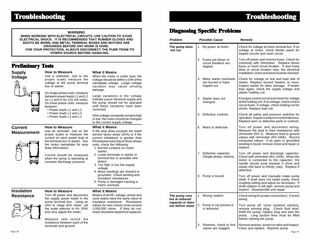
Check for voltage at motor teminal box. If novoltage at motor, check feeder panel fortripped circuits and reset circuit.
Turn off power and remove fuses. Check forcontinuity with ohmmeter. Replace blownfuses or reset circuit breaker. If new fusesblow or circuit breaker trips, the electricalinstallation, motor and wires must be checked.
Check for voltage on line and load side ofstarter. Replace burned heaters or reset.Inspect starter for other damage. If heatertrips again, check the supply voltage andstarter holding coil.
Energize control circuit and check for voltageat the holding coil. If no voltage, check controlcircuit fuses. If voltage, check holding coil forshorts. Replace bad coil.
Check all safety and pressure switches foroperation. Inspect contacts in control devices.Replace worn or defective parts or controls.
Turn off power and disconnect wiring.Measure the lead to lead resistances withohmmeter (RX-1). Measure lead to groundvalues with ohmmeter (RX-100K). Recordmeasured values. If an open or groundedwinding is found, remove motor and repair orreplace.
Turn off power and discharge capacitor.Check with ohmmeter (RX-100K). When themeter is connected to the capacitor, theneedle should jump towards 0 ohms andslowly drift back to infinity ( ). Replace ifdefective.
Turn off power and manually rotate pumpshaft. If shaft does not rotate easily, checkcoupling setting and adjust as necessary. Ifshaft rotation is still tight, remove pump andinspect. Disassemble and repair.
Check wiring for proper connections. Correctwiring.
Turn pump off, close isolation valve(s),remove priming plug. Check fluid level.Refill the pump, replace plug and start thepump. Long suction lines must be filledbefore starting the pump.
Remove strainer, screen or valve and inspect.Clean and replace. Reprime pump.
1. No power at motor.
2. Fuses are blown orcircuit breakers aretripped.
3. Motor starter overloadsare burned or havetripped out.
4. Starter does notenergize.
5. Defective controls.
6. Motor is defective.
7. Defective capacitor.(Single-phase motors)
8. Pump is bound.
1. Wrong rotation
2. Pump is not primed oris airbound.
3. Strainers, check or footvalves are clogged.
TTTTTrrrrroubouboubouboubleshootingleshootingleshootingleshootingleshooting
The pump does not run
The pump runsbut at reducedcapacity or doesnot deliver water
Page 19
TTTTTrrrrroubouboubouboubleshootingleshootingleshootingleshootingleshooting
What it MeansIf the amp draw exceeds the listedservice factor amps (SFA) or if thecurrent imbalance is greater than5% between each leg on three-phaseunits, check the following:1. Burned contacts on motor
starter.2. Loose terminals in starter or
terminal box or possible wiredefect.
3. Too high or too low supplyvoltage.
4. Motor windings are shorted orgrounded. Check winding andinsulation resistances.
5. Pump is damaged causing amotor overload.
How to MeasureTurn off power and disconnectthe supply power leads in thepump terminal box. Using anohm or mega ohm meter, setthe scale selector to Rx 100Kand zero adjust the meter.
Measure and record theresistance between each of theterminals and ground.
What it MeansMotors of all HP, voltage, phase andcycle duties have the same value ofinsulation resistance. Resistancevalues for new motors must exceed1,000,000 ohms. If they do not,motor should be repaired or replaced.
How to MeasureUse an ammeter, (set on theproper scale) to measure thecurrent on each power lead atthe terminal box or starter. Seethe motor nameplate for ampdraw information.
Current should be measuredwhen the pump is operating atconstant discharge pressure.
PrPrPrPrPreliminareliminareliminareliminareliminary y y y y TTTTTestsestsestsestsests
CurrentMeasurement
WARNINGWHEN WORKING WITH ELECTRICAL CIRCUITS, USE CAUTION TO AVOID
ELECTRICAL SHOCK. IT IS RECOMMENDED THAT RUBBER GLOVES ANDBOOTS BE WORN, AND METAL TERMINAL BOXES AND MOTORS ARE
GROUNDED BEFORE ANY WORK IS DONE.FOR YOUR PROTECTION, ALWAYS DISCONNECT THE PUMP FROM ITS
POWER SOURCE BEFORE HANDLING.
How to MeasureUse a voltmeter, (set to theproper scale) measure thevoltage at the pump terminalbox or starter.
On single-phase units, measurebetween power leads L1 and L2(or L1 and N for 115 volt units).On three-phase units, measurebetween:
• Power leads L1 and L2• Power leads L2 and L3• Power leads L3 and L1
What it MeansWhen the motor is under load, thevoltage should be within ±10% of thenameplate voltage. Larger voltagevariation may cause windingdamage.
Large variations in the voltageindicate a poor electrical supply andthe pump should not be operateduntil these variations have beencorrected.
If the voltage constantly remains highor low, the motor should be changedto the correct supply voltage.
Page 18
SupplyVoltage
InsulationResistance

TTTTTrrrrroubouboubouboubleshootingleshootingleshootingleshootingleshooting
Problem Possible Cause Remedy
Page 20
4. Suction lift too large.
5. Suction and/ordischarge piping leaks.
6. Pump worn.
7. Pump impeller or guidevane is clogged.
8. Incorrect drain pluginstalled.
9. Improper coupling setting.
1. Pressure switch is notproperly adjusted or isdefective.
2. Level control is notproperly set or isdefective.
3. Insufficient air chargingor leaking tank orpiping.
4. Tank is too small.
5. Pump is oversized.
Install compound pressure gauge at thesuction side of the pump. Start pump andcompare reading to performance data.Reduce suction lift by lowering pump,increase suction line size or removing highfriction loss devices.
Pump runs backwards when turned off. Airin suction pipe. Suction pipe, valves andfittings must be airtight. Repair any leaksand retighten all loose fittings.
Install pressure gauge, start pump, graduallyclose the discharge valve and read pressureat shutoff. Convert measured pressure (inPSI) to head (in feet): (Measured PSI x 2.31ft./PSI = _____ ft.). Refer to the specificpump curve for shutoff head for that pumpmodel. If head is close to curve, pump isprobably OK. If not, remove pump andinspect.
Disassemble and inspect pumppassageways. Remove any foreign materialsfound.
If the proper drain plug is replaced with astandard plug, water will recirculate internally.Replace with proper plug.
Check/reset the coupling, see pages15-16.
Check pressure setting on switch andoperation. Check voltage across closedcontacts. Readjust switch or replace ifdefective.
Check setting and operation. Readjust setting(refer to level control manufacturer's data).Replace if defective.
Pump air into tank or diaphragm chamber.Check diaphragm for leak. Check tank andpiping for leaks with soap and water solution.Check air to water volume. Repair asnecessary.
Check tank size and air volume in tank. Tankvolume should be approximately 10 gallonsfor each gpm of pump capacity. The normalair volume is 2/3 of the total tank volume atthe pump cut-in pressure. Replace tank withone of correct size.
Install pressure gauges on or near pumpsuction and discharge ports. Start and runpump under normal conditions, record gaugereadings. Convert PSI to feet (Measured PSIx 2.31 ft./PSI = _______ ft.) Refer to thespecific pump curve for that model, ensurethat total head is sufficient to limit pumpdelivery within its design flow range. Throttlepump discharge flow if necessary.
Problem Possible Cause Remedy
Check voltage at starter panel and motor. Ifvoltage varies more than ±10%, contactpower company. Check wire sizing.
Cycle pump and measure amperage.Increase heater size or adjust trip setting toa maximum of motor nameplate (full load)current.
Check current draw on each lead to themotor. Must be within ±5%. If not, checkmotor and wiring. Rotating all leads mayeliminate this problem.
Turn off power and disconnect wiring.Measure the lead-to-lead resistance with anohmmeter (RX-1). Measure lead-to-groundvalues with an ohmmeter (RX-100K) or amegaohm meter. Record values. If an openor grounded winding is found, remove themotor, repair and/or replace.
Check proper wiring and loose terminals.Tighten loose terminals. Replace damagedwire.
Turn off power and manually rotate pumpshaft. If shaft does not rotate easily, checkcoupling setting and adjust as necessary. Ifshaft rotation is still tight, remove pump andinspect. Disassemble and repair.
Turn off power and discharge capacitor.Check with ohmmeter (RX-100K). When themeter is connected to the capacitor, theneedle should jump towards 0 ohms andslowly drift back to infinity ( ). Replace ifdefective.
Use a thermometer to check the ambienttemperature near the overloads and motor.Record these values. If ambient temperatureat motor is lower than at overloads, especiallywhere temperature at overloads is above104°F (40°C), ambient-compensated heatersshould replace standard heaters.
1. Low voltage.
2. Motor overloads areset too low.
3. Three-phase current isimbalanced.
4. Motor is shorted orgrounded.
5. Wiring or connectionsare faulty.
6. Pump is bound.
7. Defective capacitor(single-phase motors).
8. Motor overloads athigher ambienttemperature thanmotor.
Page 21
TTTTTrrrrroubouboubouboubleshootingleshootingleshootingleshootingleshooting
Fuses blow orcircuit breakersor overloadrelays trip
The pump runsbut at reducedcapacity or doesnot deliver water
Pump cycles toomuch

WWWWWorororororksheetksheetksheetksheetksheetWWWWWorororororksheetksheetksheetksheetksheet
Page 22
TTTTThrhrhrhrhree Phase Motoree Phase Motoree Phase Motoree Phase Motoree Phase MotorsssssBelow is a worksheet for calculating current unbalance on a three-phase hookup andselecting the proper wiring. Use the calculations in the left-hand column as a guide.
EXPLANATION & EXAMPLES
Here is an example of current readingsat maximum pump loads on each leg ofa three-wire hookup. You must makecalculations for all three hookups.
To begin, add up all three readings forhookup number 1, 2, and 3.
Divide the total by three to obtain the average.
Calculate the greatest current difference fromthe average.
Divide this difference by the average toobtain the percentage of unbalance.
In this case, the current unblanace for hook-up number 1 is 8%.
HOOKUP 1T1 = 51 AmpsT2 = 46 AmpsT3 = 53 Amps
TOTAL = 150 Amps
HOOKUP 1 50 Amps3 150 Amps
HOOKUP 1 50 Amps– 46 Amps 4 Amps
HOOKUP 1 .08 or 8%
50 4.00 Amps
FIGURE HERE
Page 23
HOOKUP 1L1 to T1 = ____ AmpsL2 to T2 = ____ AmpsL3 to T3 = ____ Amps
TOTAL = ____ Amps
HOOKUP 2L1 to T3 = ____ AmpsL2 to T1 = ____ AmpsL3 to T2 = ____ Amps
TOTAL = ____ Amps
HOOKUP 3L1 to T2 = ____ AmpsL2 to T3 = ____ AmpsL3 to T1 = ____ Amps
TOTAL = ____ Amps
HOOKUP 1 ____ Amps– ____ Amps
____ Amps
HOOKUP 2 ____ Amps– ____ Amps
____ Amps
HOOKUP 3 ____ Amps– ____ Amps
____ Amps
HOOKUP 1 ____ or ____%
____ ____ Amps
HOOKUP 2 ____ or ____%
____ ____ Amps
HOOKUP 3 ____ or ____%
____ ____ Amps
HOOKUP 1 _______ Amps
3 _______ Amps
HOOKUP 2 _______ Amps
3 _______ Amps
HOOKUP 3 _______ Amps
3 _______ Amps

FILMTEC Membranes
Product Information
FILMTEC Membranes • FilmTec Corporation is a wholly owned subsidiary of The Dow Chemical Company.
*Trademark of The Dow Chemical Company
RO Elements for Sanitary Applications
Dimensions – Inches (mm)Product A B C
RO-4040-FF 40.00 (1016) 0.75 OD (19) 3.9 (99)
RO-390-FF 40.00 (1016) 1.125 ID (28.58) 7.9 (200)
1. RO-4040-FF was previously named BW30-4040-LW.2. RO-390-FF replaces BW30-380-LW and BW30-8040-LW. 3. Permeate flow and salt rejection based on standard conditions: 2000 ppm NaCl, 225 psi (16 bar),
77°F (25°C), pH 8.0, and 15% recovery.4. Minimum stabilized salt rejection is 98.0%.
Operating LimitsMembrane Type.............................................................................Thin-Film CompositeMaximum Operating Temperature .............................................................113°F (45°C)Maximum Operating Pressure.............................................................600 psig (41 bar)Maximum Pressure Drop......................................................................15 psig (1.0 bar)Maximum Feed Turbidity ......................................................................................1 NTUFree Chlorine Tolerance ...........................................................Below Detectable LimitspH Range, Continuous Operation ...........................................................................3-10pH Range, Short-Term Cleaning (30 min.)* ............................................................1–12Maximum Feed Silt Density Index .........................................................................SDI 5
*Refer to Cleaning Guidelines in specification sheet 609-23010/CH 172-086-E.
1 inch = 25.4 mm
FILMTEC® RO reverse osmosis membrane elements deliver high flux and outstanding quality water for applicationsrequiring sanitary grade membrane elements. The full-fit configuration minimizes stagnant areas and is optimal forapplications requiring a sanitary design. All components comply with FDA standards.
Product Specifications
Product Part Active Surface Area Stabilized Permeate TypicalNumber ft2 (m2) Flow Rate Stabilized Salt
gpd (m3/d) Rejection
RO-4040-FF 84286 85 (7.9) 2400 (9.1) 99.5%
RO-390-FF 116314/100608 390 (36) 10,800 (40.9) 99.5%
CB
A

FILMTEC MembranesFor more information about FILMTEC membranes, call Dow Liquid Separations business:North America . . . . . . . . . . .1-800-447-4369Latin America . . . . . . . . . . .(+55) 11-5188-9277Europe . . . . . . . . . . . . . . . .(+31) 20-691-6268Japan . . . . . . . . . . . . . . . . .(+81) 3-5460-2100Australia . . . . . . . . . . . . . . .(+61) 2-9776-3226http://www.dow.com/liquidseps
Important InformationProper start up of reverse osmosiswater treatment systems is essentialto prepare the membranes foroperating service and to preventmembrane damage due tooverfeeding or hydraulic shock.Following the proper start upsequence also helps ensure thatsystem operating parametersconform to design specifications sothat system water quality andproductivity goals can be achieved.
Before initiating system start upprocedures, membrane pretreatment,loading of the membrane elements,instrument calibration and othersystem checks should be completed.
Please refer to the applicationinformation literature entitled “How toStart Up an RO Membrane System”(Form No. 609-00070/CH 172-085-E)for more information.
Operation GuidelinesAvoid any abrupt pressure or cross-flow variations on the spiral elementsduring start-up, shutdown, cleaningor other sequences to preventpossible membrane damage. Duringstart-up, a gradual change from astandstill to operating state isrecommended as follows:• Feed pressure should be increased
gradually over a 30-60 second timeframe.
• Cross-flow velocity at set operatingpoint should be achieved graduallyover 15-20 seconds.
• Permeate obtained from first hourof operation should be discarded.
General Information• Keep elements moist at all times
after initial wetting.• If operating limits and guidelines
given in this bulletin are not strictlyfollowed, the limited warranty willbe null and void.
• To prevent biological growth duringsystem shutdowns, it isrecommended that membraneelements be immersed in apreservative solution.
• The customer is fully responsiblefor the effects of incompatiblechemicals and lubricants onelements.
• Maximum pressure drop across anentire pressure vessel (housing) is60 psi (4.1 bar).
• Avoid permeate-side backpressureat all times.
Form No. 609-00274-200QRPCH 172-236-E-200*Trademark of The Dow Chemical Company
Notice: The use of this product in and of itself does not necessarily guarantee the removal of cysts and pathogens from water. Effective cyst and pathogen reduction is dependent on the complete system design and on the operation and maintenance of the system.
Notice: No freedom from any patent owned by Seller or others is to be inferred. Because use conditions and applicable laws may differ from onelocation to another and may change with time, Customer is responsible for determining whether products and the information in this document areappropriate for Customer’s use and for ensuring that Customer’s workplace and disposal practices are in compliance with applicable laws andother governmental enactments. Seller assumes no obligation or liability for the information in this document. NO WARRANTIES ARE GIVEN;ALL IMPLIED WARRANTIES OF MERCHANTABILITY OR FITNESS FOR A PARTICULAR PURPOSE ARE EXPRESSLY EXCLUDED.
Published February 2000.
USFilterUSFilterUSFilterUSFilter
10 Technology DriveLowell, Massachusetts 01851Tel: (800) 875-7873 • Fax: (978) 441-6025
Model MC10RO Controller
Installation andOperating Manual

Manual Revisions i
Model MC10 RO Monitoringand Control System
Installation and Operating Manual
Issue Date Effective Pages Description of Changes
Prototype 05/2000 - Original Issue
Rev A 07/2000 - Prototype Modifications
Rev B 01/2001 - Symbols
Rev C 03/2001 - Wiring Terminals
Rev D 03/2001 - Changes to MenuDiagram
Rev E 05/2001 - General Modifications
Rev F 05/2001 - General Modifications
Rev G 09/2001 3-3, 3-4, 3-5 Data Logger Interval
Rev H 10/2001 - Validation Modifications
Rev I 12/2001 1-4, 1-5, 3-2, Menu Level Switch Operation

Conventions and Symbols ii
Special characters, listed and described below, are used in this documentation to emphasize certaininformation.
Note: Emphasizes additional information pertinent to the subject matter.
Warning: Emphasizes information about actions which may result in personal injury.
Caution: Emphasizes information about actions which may result in equipmentdamage.
The following electrical symbols may be used in this documentation.
Symbol Meaning
Direct current.
Alternating current.
Both direct and alternating current.
Earth (ground) terminal.
Frame or chassis terminal.
!

General Limited Warranty iii
United States Filter Corporation ("USFilter") warrants the products manufactured by itagainst defects in materials and workmanship when used in accordance with theapplicable instructions for a period of one year from the date of shipment of theproducts. USFilter MAKES NO OTHER WARRANTY, EXPRESSED OR IMPLIED.THERE IS NO WARRANTY OF MERCHANTABILITY OR FITNESS FOR APARTICULAR PURPOSE. The warranty provided herein and the data, specificationsand descriptions of USFilter products appearing in USFilter’s published catalogs andproduct literature may not be altered except by express written agreement signed byan officer of USFilter. Representations, oral or written, which are inconsistent withthis warranty or such publications are not authorized and if given, should not berelied upon.In the event of a breach of the foregoing warranty, USFilter’s sole obligation shall beto repair or replace, at its option, any product or part thereof that proves defective inmaterials or workmanship within the warranty period, provided the customer notifiesUSFilter promptly of any such defect. The exclusive remedy provided herein shallnot be deemed to have failed of its essential purpose so long as USFilter is willingand able to repair or replace any nonconforming USFilter product or part. USFiltershall not be liable for consequential damages resulting from economic loss orproperty damages sustained by a customer from the use of its products.
Failure to follow the instructions presented in this manual may compromise thesafety features built into this product.
For Product and Service Information
USFilter10 Technology DriveLowell, MA 01851
Telephone: (978) 934-9349FAX: (978) 441-6025
For Technical Support – Call(800) 875-7873 Extension 5000
Warranty

Table of Contents iv
MC10 Overview 1-1Introduction 1-1Features 1-1Specifications 1-2Outputs 1-2Inputs 1-3Mode 1-4Controls 1-5Expansion Port 1-5Serial Port 1-5Data Logging 1-5
Installation 2-1Environmental 2-1Mounting 2-1Ground 2-2Connections 2-2Power 2-2I/O 2-3Outputs 2-3Inputs 2-3Conductivity 2-4Modem 2-4
Operation 3-1Controls 3-1Keypad 3-1LED Indicators 3-2Sequence 3-3Screens 3-3Main Menu 3-3Status Screen 3-3Quality Screen 3-3Alarm Log 3-3Settings Screen 3-3Settings Table 3-4Sanitization Lock 3-6Time Delays 3-7
Calibration 4-1Introduction 4-1Conductivity Calibration 4-1
Troubleshooting 4-2Temperature Calibration 4-2
Troubleshooting 4-3
Troubleshooting 5-1
AppendixMenu Diagram

MC 10 Overview 1
Introduction The MC10 Reverse Osmosis Controller is designed to control and monitor theoperating parameters of a single pump reverse osmosis water purification system.Information is displayed on a back-lit liquid crystal display, and on individual light-emitting diodes (LED). Functions and controls are operated through switches on thekeypad.
Features The MC10 incorporates the following features:
• Temperature Compensated Conductivity Monitor with Percent Rejection andAdjustable Alarm Setpoint
• Water Temperature Monitor with Adjustable High Temperature Shutdown• Three Modes of Operation: Stand-by, Tank Feed, and Direct Feed• Pretreatment Interlock• High Tank Level Shutdown• Low Tank Level Restart• Inlet Valve Control• Chemical Feed Pump Control*• Pump Control• Low Feed Pressure Sensing with Automatic Reset• High Pressure Sensing• Autoflush with Adjustable Flush Interval and Duration• Permeate Diversion Valve Output• Alarm Output• Sanitization Password Lockout• Data Logging• Ports for Expansion and Serial Communication*• Modem for remote monitoring (Optional)*
1 2 3
ENTCLR MainMenu
5 64
7 8 9
0
SYSTEM START
SYSTEM STOP
ALARM RESET
ALARM SILENCE
Main Menu <0>Mode=Direct FeedHrs Since Start=000System On
LOW QUALITY
HIGH TEMP
TANK FULL
CHEM PUMP FAIL
HIGH PRESSURE
LOW PRESSURE
PRETREATMENT OUT
OVERLOAD
Front View of Model MC10RO System Controller
* For use with non-medical VANTAGE RO systems only. (NOT for use with Med-RO systems.)
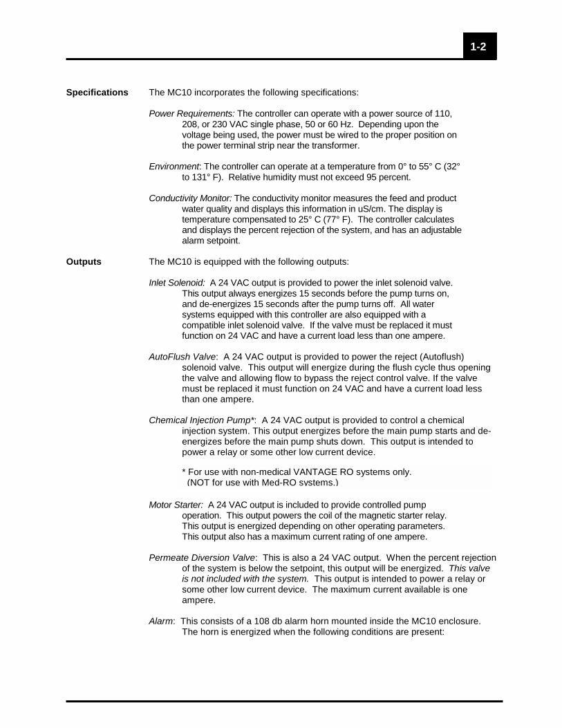
Specifications The MC10 incorporates the following specifications: Power Requirements: The controller can operate with a power source of 110,
208, or 230 VAC single phase, 50 or 60 Hz. Depending upon thevoltage being used, the power must be wired to the proper position onthe power terminal strip near the transformer.
Environment: The controller can operate at a temperature from 0° to 55° C (32°
to 131° F). Relative humidity must not exceed 95 percent. Conductivity Monitor: The conductivity monitor measures the feed and product
water quality and displays this information in uS/cm. The display istemperature compensated to 25° C (77° F). The controller calculatesand displays the percent rejection of the system, and has an adjustablealarm setpoint.
Outputs The MC10 is equipped with the following outputs:
Inlet Solenoid: A 24 VAC output is provided to power the inlet solenoid valve.This output always energizes 15 seconds before the pump turns on,and de-energizes 15 seconds after the pump turns off. All watersystems equipped with this controller are also equipped with acompatible inlet solenoid valve. If the valve must be replaced it mustfunction on 24 VAC and have a current load less than one ampere.
AutoFlush Valve: A 24 VAC output is provided to power the reject (Autoflush)
solenoid valve. This output will energize during the flush cycle thus openingthe valve and allowing flow to bypass the reject control valve. If the valvemust be replaced it must function on 24 VAC and have a current load lessthan one ampere.
Chemical Injection Pump*: A 24 VAC output is provided to control a chemical
injection system. This output energizes before the main pump starts and de-energizes before the main pump shuts down. This output is intended topower a relay or some other low current device.
Motor Starter: A 24 VAC output is included to provide controlled pumpoperation. This output powers the coil of the magnetic starter relay.This output is energized depending on other operating parameters.This output also has a maximum current rating of one ampere.
Permeate Diversion Valve: This is also a 24 VAC output. When the percent rejection
of the system is below the setpoint, this output will be energized. This valveis not included with the system. This output is intended to power a relay orsome other low current device. The maximum current available is oneampere.
Alarm: This consists of a 108 db alarm horn mounted inside the MC10 enclosure.
The horn is energized when the following conditions are present:
1-2
* For use with non-medical VANTAGE RO systems only. (NOT for use with Med-RO systems.)

• Low Pressure Shutdown• High Pressure Shutdown• High Temperature Shutdown• When Percent Rejection is Below Setpoint
All outputs are protected by positive temperature coefficient resistors (polyfuses).The polyfuses interrupt the current to the MC10 outputs should an overload conditionoccur on an output. The polyfuses will reset when power is turned off to the MC10and the fuse is allowed to cool. This eliminates the need for replaceable fuses andprevents damage caused by the incorrect fuse being installed. Both the primary andsecondary sides of the transformer in the MC10 are also protected by polyfuses.
Inputs The MC10 is equipped with the following inputs:
Conductivity Sensors: There are four inputs for each conductivity sensor, two for the
temperature detector (RTD) and two for the electrodes in the conductivitycell. Inputs are available for both the feed and product sensors. Using asensor with a cell constant of 1.0 provides a detection range of 10-1000uS/cm. Using a sensor with a cell constant of 0.1 provides a detection rangeof 1-100 uS/cm. Only sensors with a 1000 ohm RTD will work with thiscontroller.
Low Pressure Switch: This is a dry contact that signals the system to shut down if the
pump suction pressure falls below the desired value. This is a normally opencontact. When a circuit is not complete between the two terminals, thesystem will operate. If contact is made between the two terminals, thesystem will shut down. An LED will indicate when the system is in a state oflow pressure shut down. If the contacts open (pressure returns) within 30seconds of a shutdown, the system will attempt to restart. The system willmake up to five attempts at restarting. The system must be able to runcontinuously for thirty seconds without sensing low pressure. If the controllersenses low pressure after the fifth restart, it will lock out and the alarm resetbutton must be pressed to resume operation.
High Pressure Switch: This is a dry contact that signals the system to shut down if
the pump discharge or membrane pressure exceeds the desired value. Thisis a normally open contact. When an open circuit condition exists betweenthe two terminals, the system will operate. If contact is made between thetwo terminals, the system will shut down. An LED will indicate when thesystem is in a state of high pressure shut down. The alarm reset button mustbe pressed to resume operation after a shutdown due to high pressure.
Tank Level: The controller has two inputs that accept the dry contacts for the high
level and low tank level switches. If the controller is in the “Tank Feed” mode(see the “Settings menu” section of this manual for further discussion), theseswitches read the water level in the RO product storage tank and turn thepump ON or OFF depending on the level. Each switch should be installed inthe tank so that the contacts close when the water level falls below thatparticular switch. An LED will indicate when the system is in a state of hightank level “Tank Full”, the pump will turn off and the “Tank Full” LED willbegin to blink. The pump will remain off and the “Tank Full” LED willcontinue blinking until the water level drops below the low tank level switch (2level switch operation).
1-3

The MC10 may be configured to use only one tank level (high tank level) switch.Again the system must be operated in the “Tank Feed” mode (see the “Settingsmenu” section of this manual for further discussion). When this configuration is beingused, the “Tank Full” LED will indicate when the system is in a state of high tank level(level switch open). The system starts and stops based only upon high tank leveland the “High Tank Startup Delay” setpoint. When the level drops (the switch closes),the system will re-start after the “High Tank Startup Delay” (see “Settings Menu”section of this manual for further discussion). The “Tank Full” LED will blink while the“High Tank Startup Delay” timer is timing. Pretreatment Interlock: This is a dry contact that signals the system to shut
down when a pretreatment device is not functioning or regenerating.This could be used on a water softener, multimedia filter, chemical feedpump, pressure differential switch on prefilters, etc. This contact isnormally closed. When a circuit is complete between the two terminalsthe system will operate. If contact is broken the system will shut down.An LED will indicate when the system is shut down due to pretreatmentinterlock. The system will restart itself when the contact is closed.
Chemical Pump Failure*: This is a dry contact that signals the failure of the
chemical injection system. This input differs from the “PretreatmentInterlock” in that it does not allow the system to restart.
All input connections on the MC10 provide a supply voltage and are designed for drycontacts. Do not apply voltage to the inputs as permanent damage may result.
Mode The MC10 is designed to operate in one of three modes. The mode of operation isselected from the Settings menu.
The stand-by mode is intended to place the system in a temporary non-operational mode. When the system is placed in this mode, it willperform a flush as scheduled by the amount of time entered for “FlushInterval” in the Settings data entry screen (See “Settings” section of thismanual). The Flush Interval is the number of minutes between flushes.The Flush Duration is the total time in seconds that unit flushes. Duringa flush, both the inlet solenoid and autoflush solenoid valves are openand the high pressure RO pump and chemical pump (if applicable) areboth running. The Permeate Diversion function and % Salt Rejectionalarm are not activated during a flush. If the Flush Duration is set forzero the system will flush for one minute. When the flush is complete,the pump will turn off and the inlet and flush valves will close. Thesystem will repeat this cycle based upon the time entered in the FlushInterval. When the system is flushing, the amount of time remaining inthe flush cycle will be indicated on the third line of the display. Whenthe system is idle, the amount of time remaining until the next flush willbe indicated.
The tank feed mode is intended to place the system in an operational mode
when feeding a storage tank. When in this mode the system will shutdown when the high tank level switch (not provided) has an opencontact. The system will restart when the low level switch closes orafter the High Tank Startup Delay interval if the system is not equipped
1-4
!
* For use with non-medical VANTAGE RO systems only. (NOT for use with Med-RO systems.)

with a low level tank switch (See “Settings” section of this manual).The flush cycle is also enabled in this mode. The controller will activatea flush only when the system starts. The Flush Duration is entered inthe Settings menu (See “Settings” section of this manual). When thesystem is autoflushing, the amount of time remaining in the flush will beindicated on the third line of the display.
The direct feed mode is intended to place the system in an operational mode
when the system is feeding a distribution loop or another piece ofequipment. In this mode the system will not flush and the tank levelswitch(es) is/are disregarded. When the system is in this mode, thetotal number of hours the system has been operated will be indicatedon the last line of the display.
All three modes of operation are controlled by the System Start and System
Stop keys. For example, if the system is put in standby mode and theSystem Start key is not pressed, the RO unit will not operate the flushcycles. This is the same for tank feed and direct feed modes, if theSystem Start key is not pressed, the RO unit will not operate. Thesystem automatically stops the RO unit whenever a change betweentank feed/direct feed and standby modes is made, requiring theoperator to restart the RO unit. “SYSTEM STOP” key must be pressedprior to changing between tank feed and direct feed operation.
Controls The MC10 is equipped with the following controls and indicators on the front panel ofthe controller.
• 4 x 20 LCD with LED Backlight• Eight LED Indicators for Alarms and Status• 20 Tactile Keys for Control and Data Entry
Expansion Port* The MC10 is equipped with one RS-485 expansion port which allows it to beequipped with additional input modules for pressure and flow. The expansion portalso allows data from the MC10 to be networked into a larger water treatmentmonitoring system. The RS-485 expansion port is the 6 pin, watertight connectorlocated in the upper right hand corner of the left hand side of the MC10 enclosure.Use of the expansion port may require a software upgrade to the MC10.
Serial Port* The MC10 is equipped with one RS-232 serial port which allows it to be equippedwith an optional internal modem module for remote monitoring and downloading ofdata (program updates, default set points, etc.). The RS-232 serial port is alsoconnected to the 5 pin, watertight connector located directly below the RS-485expansion port on the left hand side of the MC10 enclosure. Connecting to the serialport on the side of the enclosure will automatically disconnect the internal modem.
Data Logging* The MC10 is designed to log data from the RO system. This data may be retrievedlocally through the serial port connection or remotely if the MC10 unit is equippedwith the optional modem. Remote communication and retrieval of logged datarequires the use of AquaGraph PC software.
1-5
* For use with non-medical VANTAGE RO systems only. (NOT for use with Med-RO systems.)

Installation 2
Environmental The MC10 is equipped with a NEMA 4X enclosure for use in industrial environmentssubject to occasional exposure to water sprays and other wet conditions. The MC10should not be used in explosive environments. General environmental specificationsare listed below.
Environmental SpecificationsSpecification Rating
Storage Temperature -20 to 70 Deg CAmbient Operating Temperature 0 to 55 Deg CAmbient Humidity 30% to 95 % Relative Humidity (Non-Condensing)
Mounting The MC10 is designed to be mounted in a horizontal position on a flat surface bymeans of four mounting holes. Opening the front cover of the enclosure allowsaccess to the mounting holes, access to the bottom holes requires temporaryremoval of the hinge assemblies. When mounting the MC10, sufficient room shouldbe allowed on the side and bottom of the device for access to the I/O and serial portconnections. Mounting dimensions are shown below.
1 2 3
ENTCLR MainMenu
5 64
7 8 9
0
SYSTEM START
SYSTEM STOP
ALARM RESET
ALARM SILENCE
Main Menu <0>Mode=Direct FeedHrs Since Start=000System On
LOW QUALITY
HIGH TEMP
TANK FULL
CHEM PUMP FAIL
HIGH PRESSURE
LOW PRESSURE
PRETREATMENT OUT
OVERLOAD
7/8" Diameter Hole forConduit or Cord Grip
Overall Length 10.875"
Ove
rall
Hei
ght 7
.313
"
Overall Depth 5.250"
Mounting Hole Distance 10.000"
Mou
ntin
g H
ole
Dis
tanc
e 6.
469"
Cord Seals forI/O Connections
Serial Port Connector
Expansion Port Connector
Alarm Beeper

Ground A good common ground reference (earth ground) is essential for proper operation ofthe MC10. A good earth ground or power circuit ground should be connected to thethreaded stud just to the left of the power connection terminal on the enclosurebackpanel.
Connections Screw terminals are provided for making connections for sensor inputs and power.Sensor and I/O terminals are located on the inside of the door of the MC10enclosure. The terminals are numbered in ascending order from left to right. Powerterminals are on the backpanel of the enclosure. Power should always bedisconnected from the MC10 before making or changing any connections on theseterminals.
Power The incoming power is connected on the terminal blocks just below the transformeron the backpanel of the enclosure. The triple tap transformer will accept either 120,208, or 230 volts AC (50 or 60 Hz). Depending upon the voltage being used, thepower is connected to one of threeterminals as illustrated. If 460 VAC is theonly power source available, it will benecessary to use a separate step-downtransformer to lower the voltage to 230VAC.
The triple tap transformer is equipped withan internal thermal fuse on the primarywinding. This prevents damage fromoverloads should they occur.
Always replace the transformer coverafter making the power connection.
2-2
343332313029282726252423222120191817161510090807060504030201 14131211 373635
Terminal Blocks for I/Oand Sensor Connections Terminal Blocks for
Power Connections0
VAC
120
VAC
208
VAC
230
VAC
Conn
ect A
C Ne
utra
l Her
e
If 12
0 VA
C, C
onne
ct H
ere
If 20
8 VA
C, C
onne
ct H
ere
If 23
0 VA
C, C
onne
ct H
ere
Conn
ect G
roun
d He
re
0 120
208
230

I/O The wiring diagram for the input and output connections is shown below.
Outputs All outputs (with the exception of the external alarm) are 24 VAC, one amp maximum.Any device connected to an output should be rated for less than one amp at 24 VAC.An overload on any output will cause current to be interrupted to the output and analarm condition will occur. If the transformer supplying the controller becomesoverloaded, the controller will reboot. If the overload still exists after the controllerreboots, the controller will shut down the system and log an overload alarm.
The external alarm output is 12 VDC, 100 mA maximum. This output is designed todrive small loads such as indicator lights or small alarm horns.
Avoid using excessively large wire (larger than 18 AWG) to wire the outputs since itmay prevent the enclosure door from closing properly. All wires from the outputsmust pass through the rubber grommet in the cord seal. Any unused openings in thegrommet must be sealed with plugs to maintain the watertight characteristics of theenclosure.
Inputs All inputs should be dry contacts rated for 24 VAC. Do not apply voltage to theinputs. Input voltage to the contacts is supplied by the MC10.
Avoid using excessively large wire (larger than 18 AWG) to wire the inputs since itmay prevent the enclosure door from closing properly. All wires from the inputs mustpass through the rubber grommet in the cord seal. Any unused openings in thegrommet must be sealed with plugs to maintain the watertight characteristics of theenclosure.
2-3
Perm
Con
d (W
hite
)
Perm
Con
d (S
hiel
d)
Perm
Con
d (B
lack
)
Feed
Con
d (W
hite
)
Feed
Con
d (S
hiel
d)
Feed
Con
d (B
lack
)
Feed
Tem
p (R
ed)
Feed
Tem
p (G
reen
)
Perm
Tem
p (R
ed)
Perm
Tem
p (G
reen
)
Perm
eate
Con
duct
ivity
Sen
sor
Feed
Con
duct
ivity
Sen
sor
Whi
teRe
dSh
ield
Gre
enBl
ack
Whi
teRe
dSh
ield
Gre
enBl
ack
DC N
egat
ive
Alar
m O
utpu
t 12
VDC
Perm
eate
Dive
rsio
n Va
lve O
utpu
t 24
VAC
Mot
or S
tarte
r Out
put 2
4 VA
C
Chem
Pum
p O
utpu
t 24
VAC *
Auto
Flu
sh V
alve
Out
put 2
4 VA
C
Inle
t Val
ve O
utpu
t 24
VAC
AC N
eutra
l
AC N
eutra
l
AC N
eutra
l
AC N
eutra
l
AC N
eutra
l
24 V
AC
24 V
AC
24 V
AC
24 V
AC
24 V
AC
Low
Pres
sure
Swi
tch
Inpu
t
High
Pre
ssur
e Sw
itch
Inpu
t
Mid
Tan
k Le
vel S
witc
h In
put
High
Tan
k Le
vel S
witc
h In
put
Pret
reat
men
t Int
erlo
ck In
put
24 V
AC
Chem
Pum
p Fa
ilure
Inpu
t *
Gro
und
AC N
eutra
l
24 V
AC
From
Bac
kpan
el
From
Tra
nsfo
rmer
From
Tra
nsfo
rmer
01 02 03 04 05 06 07 08 09 10 11 12 13 14 15 16 17 18 19 20 21 22 23 24 25 26 27 28 29 30 31 32 33 34 35 36 37
* For use with non-medical VANTAGE RO systems only.(NOT for use with Med-RO systems.)
!

Pretreatment Interlock: This input is designed to be normally closed. If apretreatment interlock input is not being connected, a wire jumper mustbe installed between the two terminals at Input 5. Since the input isnormally closed, multiple devices may wired to this input in series.
Pretreatment Failure: This input is designed to be normally closed. If apretreatment failure input is not being connected, a wire jumper mustbe installed between the two terminals at Input 6. Since the input isnormally closed, multiple devices may wired to this input in series.
Tank Level Switches: The MC10 is designed to be used with one or two tanklevel switches. Switches should be wired in the normally closedposition (the switch contacts close when the water level drops belowthe switch). When using two switches, a low-level tank switch startsthe system (in Tank Feed mode) and a high-level switch stops thesystem. When using one switch, the switch connected must be a high-level switch. The switch will stop the system at high level. When thelevel drops (the switch closes), the system will re-start after the “HighTank Startup Delay”, in minutes (See “Settings” section of this manual)that has been configured into the Settings data entry screen. Thecontroller must be configured for one or two switch operation in theSettings menu (See “Settings” section of this manual).
Conductivity The MC10 is designed to monitor conductivity by means of a standard two electrodeconductivity cell. Cells with constants of 1.0 must be used. When using a 1.0 cell,the conductivity range will be 0-1000 uS/cm. The cells should be equipped with atwo-wire, 1000 ohm Platinum RTD.
Conductivity cells should be connected by means of Belden cable no. 8724 orequivalent. When routing the conductivity cables, stay clear of AC cables, motors, orother sources of electrical interference. Never run sensor cables in the same conduitwith AC cables.
Modem* The optional modem for the MC10 is housed inside the MC10. The modem isconnected by plugging the ribbon cable connector onto the dual row connectorlocated on the I/O board under the I/O cover plate. The modem is equipped with astandard RJ connector for connection to an analog phone line. Do not connect theMC10 modem to an intra-office digital phone line. Damage to the modem canoccur. Once connected to a modem, the MC10 can be accessed by means ofWindows-based AquaGraph software for remote monitoring or data retrieval.
2-4
!
* For use with non-medical VANTAGE RO systems only. (NOT for use with Med-RO systems.)

Operation 3
Controls The MC10 is housed in a NEMA 4X enclosure with a membrane keypad. Indicatorsinclude a 4 line x 20 character LCD with LED backlight and eight high intensity LEDindicators for alarm conditions. The control features of the MC10 are illustratedbelow.
Keypad The membrane keypad contains 20 tactile keys which are used for a number ofcontrol and data entry functions.
System Start: Pressing this key starts the system. If the Direct Feed mode hasbeen chosen, pressing the System Start key immediately initiates thestartup sequence. If the Tank Feed mode has been chosen, pressingthis key will not initiate the startup sequence unless the tank is belowhigh-level. Pressing this key in Stand-By mode will initiate the flushsequence of flush cycles.
System Stop: Pressing this key stops the system and essentially turns all
functions off. Alarm Reset: Pressing this key resets the system after an alarm shut down for
low pressure, high pressure, low quality, high temperature, overload, orchemical injection failure (VANTAGE RO systems only).
1 2 3
ENTCLR MainMenu
5 64
7 8 9
0
SYSTEM START
SYSTEM STOP
ALARM RESET
ALARM SILENCE
Main Menu <0>Mode=Direct FeedHrs Since Start=000System On
LOW QUALITY
HIGH TEMP
TANK FULL
CHEM PUMP FAIL
HIGH PRESSURE
LOW PRESSURE
PRETREATMENT OUT
OVERLOAD
LED Alarm and Status Indicators
LCD Display with Backlight
Keys Used for System Control
Keys Used for Data Entry and Configuration

Alarm Silence: Pressing this key silences the alarm horn. The system will still
shut down if the alarm condition does not correct itself before theshutdown delay expires (See “Settings” section of this manual).
Up Arrow, Down Arrow, Right Arrow: These keys are used to move through the
display screens and for data entry purposes.
ENT: This key is used to confirm (ENTER) the various setting values. CLR: This key is used to clear an erroneous data entry. The data must be
cleared before pressing the ENT key. Numbers 0-9: These keys are used for data entry as well as for accessing
various screens directly or for making other selections.
LED Indicators The eight LED indicators are used to indicate various status and alarm conditions.
Chem Pump Failure*: Indicates when the system is experiencing failure of thechemical injection system. The system will shut down after the chempump failure time delay expires.
Pretreatment Interlock: Indicates when the system is shut down due to externalpretreatment equipment.
Tank Full: LED Solid - Indicates when the storage tank is full. LED Blinking –
The tank level is transitioning between the High and Low Tank levels.The system will only shut down when in the Tank Feed mode.
Low Quality: Indicates that the percent rejection is below the alarm setpoint. Low Pressure: Indicates that the system has experienced low pump feed
pressure. The system will shut down after the low pressure time delayexpires. The system will automatically restart up to five times after alow pressure shutdown. After which, the “ALARM RESET” key mustbe pressed before restarting.
High Pressure: Indicates that the system has experienced high pump or
membrane pressure. The system will shut down after the high pressuretime delay expires.
High Temperature: Indicates that the system has experienced high feed or
product water temperature. The system will shut down after the hightemperature shutdown time delay expires.
Overload Condition: Indicates that the system has experienced an overload
condition on one of the outputs. It will also indicate if the controllertransformer has been overloaded due to excessive loads on multipleoutputs. The system will shut down after the overload time delayexpires. In the case of a transformer overload, the system will shutdown and the indicator will illuminate if the controller “reboots” due toan overloaded condition.
3-2
* For use with non-medical VANTAGE RO systems only. (NOT for use with Med-RO systems.)

Sequence The normal startup and shut down sequence for the system is listed below. In Direct
Feed mode, this sequence is initiated when the System Start key is pressed. Whilein Direct Feed mode, the system will not shut down unless the System Stop key ispressed or an alarm occurs. In Tank Feed mode, this sequence will be initiatedevery time the system starts and stops as controlled by tank level. When in TankFeed mode, this sequence will also be used for the autoflush cycles with the additionof the activation of the autoflush solenoid valve. When in Stand-By mode, thissequence is used for the autoflush cycles with the addition of the activation of theautoflush solenoid valve.
Startup Shutdown
Open Inlet Valve Stop PumpOpen Autoflush Valve (during autoflush sequence only) Fifteen Second DelayStart Chemical Feed (VANTAGE RO systems only) Close Inlet ValveTen Second Delay Close Autoflush Valve (if open)Start Pump
The autoflush sequence is activated only in the Tank Feed and Stand-By modes ofoperation. Autoflush interval and duration are controlled by the interval and durationpresets configured into the MC10 in the Settings menu.
Screens The MC10 displays data and operating status by means of a number of screensdisplayed on the LCD. Specialized screens are also used for configuring the systemand for entering setpoints, time delays, deadbands, etc. The next page illustrates thescreens displayed by the MC10.
Main Menu The Main Menu consists of two screens which are accessed using the up and downarrow keys. The Main Menu screen displays the current operating mode, run status,and either hours since start (Direct Feed mode) or autoflush information (Standbymode). Only current operating mode and run status will be indicated while in TankFeed mode. The Main Menu screen also allows the user to access other screens.
Status Screen Status screen is accessed by pressing the number 2 on the keypad from the secondMain Menu screen. The Status screen displays the total run time (RT) in 100 hoursindicated as tenths of 1000 hours (As an example 0.0257 is the same as 257 hours)along with the time remaining until the next service, which is indicated in 1000 hourincrements. When service is due, the words “Call for Service” will flash at the bottomof the Main Menu screen.
Quality Screen Quality screen is accessed by pressing the number 3 on the keypad from the secondMain Menu screen. The Quality screen displays the feed conductivity (FCnd),permeate conductivity (PCnd), feed temperature (in degrees C), and percentrejection (%SR).
Alarm Log Alarm Log screen is accessed by pressing the number 4 on the keypad from thesecond Main Menu screen. The user may tab through the alarm log by using the upand down arrow keys. The Alarm Log will hold up to 256 alarms along with the timeand date of the alarm. In the event that Alarm Log needs to be cleared, press theright arrow key on the keypad. The user is prompted for the access code to clear theAlarm Log (factory default access code = 12345).
Settings Screen Settings screen is accessed by pressing the number 5 on the keypad from thesecond Main Menu screen. The Settings screen itself has six selections. The firstselection, number 0 on the keypad, allows the user to set the time (hours, minutes
3-3

and seconds), date (day, date, month and year) access (factory default access code= 12345) and sanitize lockout (factory default sanitize lockout code = 12345) codes.
The MC10 maintains time on a 24 hour clock (i.e., military style). The hours,minutes, and seconds are changed on separate screens by entering the appropriatenumber and pressing “ENTER”. Date, month, and year are entered in the samefashion. The MC10 also requires that the day of the week be entered (Sunday = 1,Saturday = 7).
The second selection from the Settings Screen, number 1 key, allows the user tochange the operating mode of the MC10; Sanitize, Standby or Tank/Direct Feedmodes. The third selection, number 2 key, allows access to the Settings data entryscreens. The user is prompted for the access code to enter sub menu 0 (Clock) or 2(Settings) of the Settings screen (factory default access code = 12345).
The fourth selection, number 3 key, automatically initializes the modem. This onlyneeds to be done one time after a modem is installed in the controller. The fifthselection, number 4 key, allows the user to select the data log interval. The sixthselection, number 5 key, erases the data currently in the data logger.
Upon entering the Settings data entry screens (by pressing “2” from the mainSettings screen), the user will have the option of entering an index number for aparticular setting. This enables the user to go directly to a particular setting withoutscrolling through the entire list of settings. Alternatively, the user may scroll throughthe settings with the up and down arrow keys.
Settings Table The table below lists the index number of all of the Settings data entry screens, theabbreviation used on the screen, the full name of the setting, and any other pertinentinformation on that particular setting.
Settings Table
NOTE: Where required, the right arrow key is used to enter the decimal point.
MC10 SettingsIndex Screen Name Full Name Range Format Default
Setting Details
0 Feed Tank or DirectFeed 0 or 1 0 1
Allows the user to choose between tankfeed or direct feed operation. Enter 0 fortank feed or 1 for direct feed.
1 Low Salt Rjct SP %Low SaltRejectionSetpoint
80-100 00.0 90 Setpoint (in %) which activates the alarmfor low salt rejection.
2 Low Salt Rjct DB %Low SaltRejectionDeadband
0-20 00.0 0.5Deadband (in %) through which the saltrejection value must increase to releasethe low salt rejection alarm.
3 Low Salt Rjct TDsecLow SaltRejectionTime Delay
1-255 000 1Delay (in seconds) before the low saltrejection alarm is activated once thecurrent value falls below the setpoint.
4 Low Salt Rjct SDsecLow SaltRejection ShutDown Delay
1-255 000 1Delay (in seconds) before the systemshuts down after the low salt rejectionalarm is activated.
5 Perm Divert SP %PermeateDiversionSetpoint
80-100 00.0 80Permeate conductivity setpoint (in %)which activates the permeate diversionvalve.
6 Perm Divert DB %PermeateDiversionDeadband
0-20 0.0 1.0Deadband (in %) through which thepermeate conductivity value mustincrease before the permeate diversionvalve is released.
3-4

7 Perm Divert TD SecPermeateDiversionTime Delay
1-255 000 15Delay (in seconds) before the permeatediversion valve is activated once thecurrent value falls below the setpoint.
8 High Temp SP DegCHighTemperatureSetpoint
0-45 00 32 Temperature setpoint (in deg C) whichactivates the high temperature alarm.
9 High Temp DBDegC
HighTemperatureDeadband
0.1-10 0.0 3Deadband (in deg C) through which thetemperature value must pass before thehigh temperature alarm is released.
10 High Temp TD SecHighTemperatureTime Delay
1-255 000 20Delay (in seconds) before the hightemperature alarm is activated once thecurrent value rises above the setpoint.
11 High Temp ShtdwnSec
HighTemperatureShut DownDelay
1-255 000 10Delay (in seconds) before the systemshuts down after the high temperaturealarm is activated.
12 High Tank Lvl TDSec
High TankLevel TimeDelay
1-255 000 5 Delay (in seconds) before the systemshuts down for high tank level.
13 Low Tank Swtch EN Low TankSwitch Enable 0 or 1 0 1
Allows the system to be configured withor without a low tank level switch. Enter“1” to enable (low tank level switchpresent) or “0” to disable (low tank levelnot being used) this feature.
14 Hi Tnk Startup SecHigh TankLevel RestartTime Delay
1-1000 000 30
Delay (in seconds) before the system willrestart after the tank level drops belowthe high tank level switch. This feature isonly used when the system is configuredfor operation without a low tank levelswitch.
15 Low Tank Lvl TDSec
Low TankLevel TimeDelay
1-255 000 5Delay (in seconds) before the systemrestarts (in Tank Feed mode) when thelevel drops below the low tank levelswitch.
16 High Pressure TDSec
High PressureTime Delay 1-255 000 5 Delay (in seconds) before the system
shuts down for high pressure.
17 Low Pressure TDSec
Low PressureTime Delay 0-255 000 5 Delay (in seconds) before the system
shuts down for low pressure.
18 Overload TD Sec OverloadTime Delay 1-255 000 2 Delay (in seconds) before the system
shuts down for output overload.
19 Pretrt Intlk TD SecPretreatmentInterlock TimeDelay
1-255 000 2 Delay (in seconds) before the systemshuts down for pretreatment interlock.
20* Chem Pump TD SecChemicalPump FailureTime Delay
0-100 000 2Delay (in seconds) before the systemshuts down for failure of the chemicalinjection pump.
21 Flush Interval Min Auto FlushInterval 1-90 000 60 Interval (in minutes) between autoflush
cycles.
22 Flush Duration Sec Auto FlushDuration 1-360 000 180 Duration (in seconds) of each autoflush
cycles.
23 Feed CND StandardFeedConductivityStandard
10-3000 0000 NA
24 Perm CND StandardPermeateConductivityStandard
0-1000 00.0 NA
With these settings, the user cancalibrate the conductivity inputs to astandard solution. See Calibrationsection for more information.
25 Feed Temp Zero
FeedTemperatureZeroCalibration
1-1500 000 NA
This setting allows the temperaturesensor in the feed conductivity cell to becalibrated to zero degrees C. Onlyqualified users following the proceduresdocumented in the Calibration section ofthis manual should adjust this setting.
3-5
* For use with non-medical VANTAGE RO systems only. (NOT for use with Med-RO systems.)

26 Feed Temp SpanDegC
FeedTemperatureSpanCalibration
1-60 00.0 NA
This setting allows the temperaturesensor in the feed conductivity cell to becalibrated to a known temperature atspan value. Only qualified usersfollowing the procedures documented inthe Calibration section of this manualshould adjust this setting.
27 Perm Temp Zero
PermeateTemperatureZeroCalibration
1-1500 000 NA
This setting allows the temperaturesensor in the permeate conductivity cellto be calibrated to zero degrees C. Onlyqualified users following the proceduresdocumented in the Calibration section ofthis manual should adjust this setting.
28 Perm Temp SpanDegC
PermeateTemperatureSpanCalibration
1-60 00.0 NA
This setting allows the temperaturesensor in the permeate conductivity cellto be calibrated to a known temperatureat span value. Only qualified usersfollowing the procedures documented inthe Calibration section of this manualshould adjust this setting.
Sanitization Lock From the Operating Mode screen, the user may select “Sanitization Lock”; MainMenu <1> screen, select keypad number 5 (Settings), select keypad number 1(Mode), select keypad number 1 (San lock). Following this the RO unit will be placedin the Sanitization lockout mode. If the RO is currently operating, the RO unit willimmediately shutoff, the controller display will indicate MODE=Sntz Lock and MIN(minutes) since Lock. If the RO unit is not currently running, regardless of mode ofoperation, all operation sequencing will immediately cease, the RO unit will placed ina controls level lockout condition and the controller display will indicate MODE=SntzLock and MIN (minutes) since Lock. This prevents the system from operating from acontrols standpoint while sanitizing agents are present.
The controller must be powered up (display illuminated) for the sanitization feature tooperate properly, in the event that power is interupted during a sanitizationprocedure, the controller will remain locked out of service.
Following the sanitization process, pressing any of the arrow keys or the green“MAIN MENU” key on the keypad will prompt the operator to enter the unitsanitization lockout code, “LOCKOUT RESTART”, “Enter Access Code” will bedisplayed. The operator must enter the five digit sanitization lockout code to exit thesanitization lockout mode. Following this RO unit may once again be operated in anyof the three available normal operating modes.
Refer to the RO unit Operation and Maintenance manual accompanying the unit forproper sanitization precautions, proper materials and procedures.
3-6

Time Delays Time delays and deadbands are used to control the action of the MC10 alarms.These are described below.
The illustration above shows the action of a low alarm setpoint on a falling value.
The high setpoint works in the same manner except the deadband is below thesetpoint.
Proc
ess
Valu
e
Time
Low Alarm Setpoint
Deadband
TimeDelay
Alarm Activates at End of Time Delay
Alarm is Released When Rising Process ValueExceeds Setpoint Plus Deadband
Proc
ess
Valu
e
Time
High Alarm Setpoint
Deadband
TimeDelay
Alarm Activates at End of Time Delay
Alarm is Released When Rising Process ValueDrops Below Setpoint Minus Deadband
3-7

Calibration 4
Introduction A number of parameters monitored by the MC10 must be periodically calibrated foroptimum performance and accuracy. These are outlined below.
MC10 Calibration
Parameter Method of CalibrationSettings
IndexNumber
RecommendedCalibrationFrequency
Feed Conductivity Calibration with ConductivityStandard Solution 23
PermeateConductivity
Calibration with ConductivityStandard Solution 24
One to ThreeMonths DependingUpon SampleCondition
Feed TemperatureZero Calibration to Zero Degrees C 25
Feed TemperatureSpan
Calibration to KnownTemperature 26
PermeateTemperature Zero Calibration to Zero Degrees C 27
PermeateTemperature
Calibration to KnownTemperature 28
Six Months
Conductivity The conductivity inputs of the MC10 should be calibrated using a known standardsolution. Value of the standard should be in the upper area of the range of theconductivity being measured by the MC10.
In cases of low conductivity (< 50 uS/cm) it may be necessary to calibrate the sensorand its associated input channel in situ. This is done by following the same generalprocedure as outlined below for calibration to a standard solution with one exception.In situ calibration requires that the sensor be left mounted in the process line.Instead of using a standard solution, a sample from the process line is tested with acalibrated meter. This measured conductivity value of the process fluid is used in lieuof a standard solution value.
The following procedure should be used for calibrating the MC10 to a solution ofknown conductivity.
Step One – Rinse or soak the sensor in deionized water. Dry the sensor and place itin a solution of known conductivity. This may be a standard solution provided alaboratory supply company or a water sample which has been measured by acalibrated conductivity meter. Make sure that the conductivity value of the calibrationsolution is within the upper range of the MC10 conductivity channel. Allow thesensor to equalize to the solution temperature for a few minutes before proceedingwith the next step.

Important Please note:
• Temperature and conductivity are combined in one sensor.• If temperature and conductivity are both being calibrated, always calibrate the
temperature first.• Be careful not to damage (avoid excessive twisting, bending, etc.) the sensor
leads when removing the sensor from the pipe fitting.• Never reuse standard solutions. Always dispense the solution from its container
and dispose of the solution after using it.• Use clean containers (triple rinsed with deionized water) for holding the
calibration solution.
Step Two – Go to the appropriate Settings data entry screen (23 or 24). Enter thevalue of the calibration solution via the keypad. Press ENTER. A new measuredvalue will appear on the screen.
If the value displayed on the screen does not match the value entered for thecalibration solution, let the sensor equalize for a few more minutes and repeat StepTwo.
Troubleshooting If problems occur during calibration, please check the following:
• Ensure that the Settings screen corresponds to the sensor being calibrated.• Check the condition of the sensor. Make sure that the electrode surfaces are not
damaged, corroded, or fouled.• Make sure that the sensor is suitable for use with the MC10. Verify that the cell
constant is in the correct range and that the sensor is equipped with the propertemperature element (1000-Ohm Platinum RTD).
• Check the condition of the sensor wiring and that the sensor leads are properlyconnected to the MC10 terminals.
• Verify that the calibration solution is the correct conductivity value and that thevalue is within the range of the conductivity input being calibrated.
• Refer to the Troubleshooting Section of the manual for more information.
Temperature The temperature elements in the conductivity sensors are calibrated in a similarfashion as the conductivity sensors. Follow these steps for temperature calibration.
Step One – Place the conductivity sensor in an ice bath. Allow the sensor toequalize for a few minutes.
Important Please note:
• Temperature and conductivity are combined in one sensor.• If temperature and conductivity are both being calibrated, always calibrate the
temperature first.
4-2
SETTINGS >26< FCnd=XXX Feed CND Standard OLD=1000 New=?
Conductivity Being Measured by Sensor(Updates Only When "ENTER" is Pressed)Settings Screen
Index Number
Standard Value (uS) PreviouslyUsed for Calibration
Enter Value of CalibrationSolution (uS) Via Keypad

• Be careful not to damage (avoid excessive twisting, bending, etc.) the sensorleads when removing the sensor from the pipe fitting.
• The conductivity standard solution may be used for temperature calibration whencombining the temperature and conductivity calibrations.
Step Two – Go to the appropriate Settings data entry screen (25 or 27). Thefollowing screen will appear:
The screen will display the raw analog value being measure from the temperaturesensor. Enter this value from the keypad and press ENTER. The value shown nearthe top of the screen should match the value entered. If not, wait a minute longerand re-enter the number.
Step Three – Place the conductivity sensor in a water sample at approximately thesame temperature as that being monitored in the process. Measure the temperaturewith a laboratory grade thermometer. Allow the sensor to equalize to the solutiontemperature for a few minutes before proceeding with the next step.
Step Four – Go to the appropriate Settings data entry screen (26 or 28). Enter thetemperature of the calibration solution via the keypad. Press ENTER. A newmeasured value will appear on the screen.
If the value displayed on the screen does not match the value entered for thecalibration solution, let the sensor equalize for a few more minutes and repeat StepTwo.
Troubleshooting If problems occur during calibration, please check the following:
• Ensure that the Settings screen corresponds to the sensor being calibrated.• Check the condition of the sensor. Make sure that the electrode surfaces are not
damaged, corroded, or fouled.• Make sure that the sensor is suitable for use with the MC10. Verify that the
sensor is equipped with the proper temperature element (1000-Ohm Pt RTD).• Check the condition of the sensor wiring and that the sensor leads are properly
connected to the MC10 terminals.• Refer to the Troubleshooting Section of the manual for more information.
SETTINGS [>]=[.] >28< FTmp=XXX FTemp Calibration OLD=20 New=?
Temperature Being Measured by Sensor(Updates Only When "ENTER" is Pressed)Settings Screen
Index Number
Calibration Value (Deg C) PreviouslyUsed for Calibration
Enter Temperature of CalibrationSolution (Deg C) Via Keypad
4-3
SETTINGS>25< FdZero=XXX Feed Temp Zero OLD=819 New=?
Raw Value Being Measured by Sensor(Updates Only When "ENTER" is Pressed)Settings Screen
Index Number
Raw Value PreviouslyUsed for Calibration
Enter Raw Value BeingMeasured

Troubleshooting 5
The MC10 Reverse Osmosis Controller is designed for ease of maintenance andminimum service. Since the highest quality of electronic semiconductor componentsare used in this design, it is not likely that circuit malfunctions or failures will occur. Itis our recommendation that service be limited to identifying malfunctions at the boardlevel and that component level troubleshooting be referred to USFilter’s TechnicalSupport Department (see the phone number listed on the cover of this manual.)It is our experience that field failures which most frequently occur are:
• Improper or broken wiring connections• Incorrect wiring of magnetic starter• Improper grounding• Cable run is too long• Water in connectors• Dirty cell electrodes• Defective conductivity/temperature probes
Troubleshooting
Type of Problem Possible Cause or Solution
1. Motor draws too much current andtrips magnetic starter.
1. Motor overloaded, pump notrotating freely.
2. Bearing defective.
3. Power distribution not even,check voltages and currentdraw on each leg.
4. Check pin connectors.
5. Current imbalance (3-phaseonly)
6. Loss of power on 1 leg (3-phase only)
2. Controller shuts down on lowpressure, but pressure in line isokay.
1. Check setting of pressureswitch.
2. Check pressure switch wiring,must be wired normally closed.
3. Defective switch, contacts can

Type of Problem Possible Cause or Solution
be corroded or diaphragmcould be defective.
4. Make sure wiring fromcontroller to pressure switchare shielded wires. Also routewire away from any AC lines ormotor windings.
5. Inlet to pressure switch isobstructed.
3. Motor starter trips repeatedly. 1. Verify wiring to and from coiland controller.
2. Verify that the overload relay isset according to ratingspecified on motor nameplate.
3. Check the secondary voltageon the transformer (should be24 VAC ± 2 volts).
4. Controller display shows “SystemOn” but system does not run.
1. Verify wiring.
2. Check motor starter foroverload.
3. Controller is in Tank Mode andtank is full.
4. Controller is in Stand-By Modeand system is between autoflush cycles.
5. RO Controller shuts off, does notrestart, and no alarm indication ispresent.
1. Possible brown out, or poweroutage reset the controller to“System Off”.
6. RO Controller shuts down on hightemperature even though thetemperature is below setpoint.
1. Calibrate temperature sensor.
2. Check sensor wiring.
5-15-2

Type of Problem Possible Cause or Solution
9. Conductivity monitor shows readingto be higher than known solution.
1. Check calibration of each cell.
2. Sensor electrode not fullyimmersed.
3. Air bubbles in sensing area.
4. Fouled sensor.
5. Defective sensor wiring.
6. Relocate sensor.
7. Clean sensor electrode.
8. Check sensor wiring.
10. Conductivity monitor does notrespond to known solution.
1. Calibrate sensors.
2. Check/replace sensors.
3. Check/replace leads tosensors.
11. Conductivity monitor shows lowreading for known conductivitychanges.
1. Sensor electrode obstructed.
2. Inadequate solution circulation.
3. Clean or relocate sensor.
12. Conductivity reading is erratic. 1. Faulty sensor.
2. Faulty sensor wiring.
3. Moisture in cables.
5-3

Main Menu <0>
Mode=Direct Feed
Hrs Since Start=000
System On 00:00:00
Main Menu <1>
2)Status 3)Quality
4)Alarms 5)SettingS
02/01/00 00:00:00
QUALITY
FCnd[uS/cm]=000
PCnd[uS/cm]=00
T[C]=00 %SR=00.0
STATUS
RT(1000 Hrs)=0.0000
Hrs To Srvc=0000
02/01/00 00:00:00
<0> ALARM LOG
Low %SR
00:00:00 02/01/00
Press [->] to Clear
SETTINGS
0)Clock 1)Mode
2)Settings 3)Modem
4)DLogger 5)Erase DL
SETTINGS
<0>
Feed 0=Tank 1=DrFd
OLD=0 NEW=?
Pres
sPr
ess
Pres
s5
Pres
s4
Pres
s2
and
Pres
s
Pres
s2
Pres
s3
ENTER ACCESS CODE
ACCESS CODE=?
CLOCK / PASSWORD
<0>
Hours
OLD=00 NEW=?
Ente
r Acc
ess
Code
and
pres
s [E
NT]
CLOCK / PASSWORD
<1>
Minutes
OLD=00 NEW=?
CLOCK / PASSWORD
<2>
Seconds
OLD=00 NEW=?
CLOCK / PASSWORD
<4>
Date
OLD=28 NEW=?
CLOCK / PASSWORD
<3>
Day (SUN=1)
OLD=1 NEW=?
CLOCK / PASSWORD
<5>
Month
OLD=12 NEW=?
CLOCK / PASSWORD
<6>
Year
OLD=2000 NEW=?
Pres
s0
to s
crol
l
up a
nd d
own
logg
ed a
larm
s.
NOTE
: Se
e se
tting
s ta
ble
in o
pera
ting
man
ual f
orco
mpl
ete
list o
f ava
ilabl
ese
tting
s an
d as
socia
ted
inde
x nu
mbe
rs.
Pres
sPr
ess
Pres
sPr
ess
Pres
sPr
ess
Pres
sPr
ess
Pres
sPr
ess
Pres
sPr
ess
Main Menu <0>
Mode=Tank Feed
System On 00:00:00
Main Menu <0>
Mode=Stand-By (Flush)
00 Min Until Flush
System On 00:00:00
Main Menu <0>
Mode=Stand-By
000 Sec Remaining
System On 00:00:00
Main Menu <0>
Mode=Sntz Lock
Min Since Lock=0
System Off 00:00:00
LOCKOUT RESTART
Enter Access Code
ACCESS CODE=?
Main Menu <0>
Mode=Direct Feed
Hrs Since Start=000
System On 00:00:00
OPERATING MODE
1)San Lock 2)Standby
3)Tank/Direct
Choice?
Pres
s1
St
and-
ByDu
ring
Flus
h
Main Menu <0>
Mode=Stand-By
System Off 00:00:00
Main Menu <0>
Mode=Tank Feed
System Off 00:00:00
Main Menu <0>
Mode=Direct Feed
System Off 00:00:00
Ente
r Acc
ess
Code
and
Pres
s [E
NT]
Pres
s An
y Ke
yPr
ess
[SYS
TEM
STA
RT]
Pres
s [S
YSTE
M S
TART
]Pr
ess
[SYS
TEM
STA
RT]
Pres
s1
Pres
s2
Pres
s3
Pres
s3
Pres
s [S
YSTE
M S
TOP]
Pres
s [S
YSTE
M S
TOP]
Pres
s [S
YSTE
M S
TOP]
MENU
DIA
GRAM
Main Menu <0>
Mode=Direct Feed
Hrs Since Start=000
System Off 00:00:00
MODEM INITIALIZATION
PLEASE WAIT
Erase Logger Memory
Access Code=?
Pres
s3
Pres
s5
Clear Data Logger?
*****Warning ******
Data will be lost!!
[Up]=Yes [Down]=No
DATA LOGGER INTERVAL
[Up]/[Down]=Interval
[->] to select
>>10 minutes<<
Pres
s4
and
Pres
sto
scr
oll
CLOCK / PASSWORD
<7>
Sntz Lock Code
OLD=12345 NEW=?
CLOCK / PASSWORD
<8>
Access Code
OLD=12345 NEW=?
Pres
sPr
ess
Pres
sPr
ess
ENTER ACCESS CODE
ACCESS CODE=?
Ente
r Acc
ess
Code
and
pres
s [E
NT]