limitorque® - flowserve corporation
TRANSCRIPT
Limitorque®
DDC-100 Master Station IIInstallation and Operation Manual
FCD LMAIM5001-00 (Replaces 435-11000)Limitorque Actuation Systems
2 DDC-100 Master Station II Installation and Operation Manual FCD LMAIM5001-00
Flow Control Division
Limitorque Actuation Systems
Master StationInstallation and Operation Manual
©2004 Copyright Flowserve Corporation. All rights reserved.
Printed in the United States of America.
Disclaimer
No part of this book shall be reproduced, stored in a retrieval system, or transmitted by any means,electronic, mechanical, photocopying, recording, or otherwise without the written permission fromFlowserve. While every precaution has been taken in the preparation of the book, the publisher assumesno responsibility for errors or omissions. Neither is any liability assumed for damages resulting from theuse of the information contained herein.
This document is proprietary information of Flowserve furnished for customer use ONLY. No other usesare authorized without written permission of Flowserve.
Flowserve reserves the right to make changes, without notice, to this document and the products itdescribes. Flowserve shall not be liable for technical or editorial errors or omissions made herein; nor forincidental or consequential damages resulting from the furnishing, performance or use of this document.
This manual contains information that is correct to the best of Flowserve’s knowledge. It is intended to bea guide and should not be considered as a sole source of technical instruction, replacing good technicaljudgment, since all possible situations cannot be anticipated. If there is any doubt as to exact installation,configuration, and/or use, please contact Flowserve at 1-800-225-6989.
The choice of system components is the responsibility of the buyer, and how they are used cannot be theliability of Flowserve Corporation. However, Flowserve’s sales team and application engineers are alwaysavailable to assist you in making your decision.
MS-DOS® is a registered trademark of Microsoft Corporation.
IBM-PC® is a registered trademark of International Business Machines Corporation.
Belden® is a registered trademark of Belden, a division of Cooper Industries, Inc.

FCD LMAIM5001-00 DDC-100 Master Station II Installation and Operation Manual 3
Flow Control Division
Limitorque Actuation Systems

4 DDC-100 Master Station II Installation and Operation Manual FCD LMAIM5001-00
Flow Control Division
Limitorque Actuation Systems
FCD LMAIM5001-00 DDC-100 Master Station II Installation and Operation Manual 5
Flow Control Division
Limitorque Actuation Systems
1 Introduction
1.1 Overview
The Limitorque Master Station II is a revolutionary step forward in control technology. The device iscapable of controlling up to 250 actuators, offers full redundancy, provides easy-to-use HMI interfaces,and allows for high-speed data-transfer via a Modbus DCS port or Modbus Ethernet port. In addition, abuilt-in web server can be used for monitoring network status from any remote station using TCP/IP. Webserver operation is covered in Section 18.
1.2 User Rights Overview
The Master Station requires users to login. Three user role levels are provided: View, Control, Configure.Each role includes the rights of the lesser roles, i.e. Control includes View’s rights, and Configure includesControl’s rights and View’s rights.
View: the user can view the network status and the activity log. No control or configuration functionalityis available.
Control: in addition to View’s rights, the user has the ability to control MOVs.Configure: in addition to Control’s rights, the user has the ability to configure the Master Station and
the Network.
The default passwords for each role are:
View: 100Control: 200Configure: 300
These passwords can be changed by the Configure user. Changing passwords is discussed in Section 9.
6 DDC-100 Master Station II Installation and Operation Manual FCD LMAIM5001-00
Flow Control Division
Limitorque Actuation Systems
1.3 Login
When the Master Station starts, it loads the default startup screen (Figure 1-1).
Figure 1-1: The Introduction screen
Touching any part of the screen will load the login screen (Figure 1-2).
Note: If the screen is blank and the green LED is illuminated, touch the display to exit the screensaver mode.
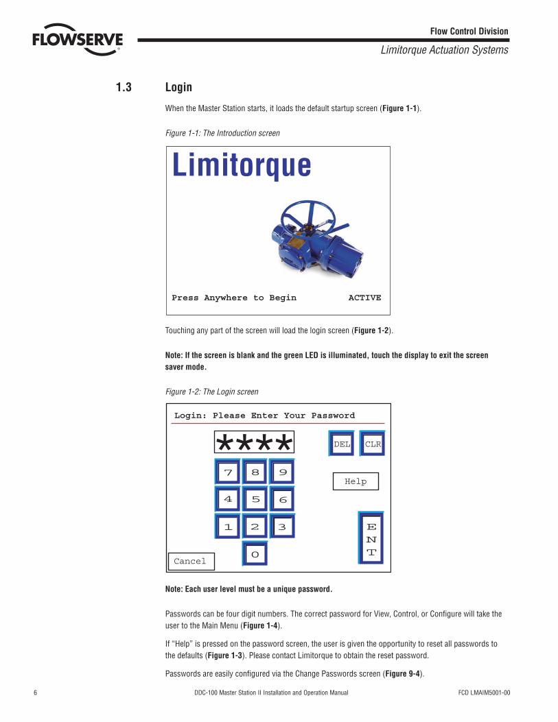
Figure 1-2: The Login screen
Note: Each user level must be a unique password.
Passwords can be four digit numbers. The correct password for View, Control, or Configure will take theuser to the Main Menu (Figure 1-4).
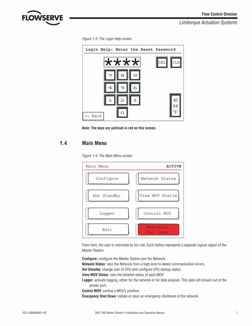
If “Help” is pressed on the password screen, the user is given the opportunity to reset all passwords tothe defaults (Figure 1-3). Please contact Limitorque to obtain the reset password.
Passwords are easily configured via the Change Passwords screen (Figure 9-4).
7 8 9
654
1 2 3
0
DEL CLR
ENT
Cancel
Help
Login: Please Enter Your Password
****
ACTIVEPress Anywhere to Begin
Limitorque
FCD LMAIM5001-00 DDC-100 Master Station II Installation and Operation Manual 7
Flow Control Division
Limitorque Actuation Systems
Figure 1-3: The Login Help screen
Note: The keys are outlined in red on this screen.
1.4 Main Menu
Figure 1-4: The Main Menu screen
From here, the user is restricted by his role. Each button represents a separate logical region of theMaster Station:
Configure: configure the Master Station and the Network.Network Status: view the Network from a high level to detect communication errors.Hot Standby: change over of CPU and configure CPU startup status.View MOV Status: view the detailed status of each MOV.Logger: activate logging, either for the network or for data analysis. This data will stream out of the
printer port.Control MOV: control a MOV’s position.Emergency Shut Down: initiate or clear an emergency shutdown of the network.
Main Menu ACTIVE
EmergencyShut Down
Control MOV
Exit
Logger
Configure
Hot Standby View MOV Status
Network Status
7 8 9
654
1 2 3
0
DEL CLR
ENT
<< Back
Login Help: Enter the Reset Password
****

8 DDC-100 Master Station II Installation and Operation Manual FCD LMAIM5001-00
Flow Control Division
Limitorque Actuation Systems
This page is intentionally blank.

FCD LMAIM5001-00 DDC-100 Master Station II Installation and Operation Manual 9
Flow Control Division
Limitorque Actuation Systems
2 Master Station II Screen Flowchart
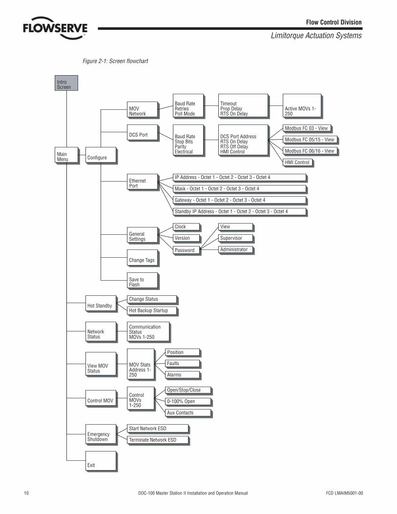
Figure 2-1 (on the following page) is a flowchart of the Master Station II screens.
10 DDC-100 Master Station II Installation and Operation Manual FCD LMAIM5001-00
Flow Control Division
Limitorque Actuation Systems
Figure 2-1: Screen flowchart
Intro Screen
Main Menu
MOV Network
DCS Port
Ethernet Port
General Settings
Change Tags
Save to Flash
Baud RateRetriesPoll Mode
TimeoutProp DelayRTS On Delay
Active MOVs 1-250
Baud RateStop BitsParityElectrical
DCS Port AddressRTS On DelayRTS Off DelayHMI Control
Modbus FC 03 - View
Modbus FC 05/15 - View
Modbus FC 06/16 - View
HMI ControlConfigure
IP Address - Octet 1 - Octet 2 - Octet 3 - Octet 4
Mask - Octet 1 - Octet 2 - Octet 3 - Octet 4
Gateway - Octet 1 - Octet 2 - Octet 3 - Octet 4
Standby IP Address - Octet 1 - Octet 2 - Octet 3 - Octet 4
Clock
Version
Password
View
Supervisor
Administrator
Hot StandbyChange Status
Hot Backup Startup
Network Status
Communication Status MOVs 1-250
View MOV Status
MOV Stats Address 1-250
Position
Faults
Alarms
Control MOVControl MOVs 1-250
Open/Stop/Close
0-100% Open
Aux Contacts
Emergency Shutdown
Start Network ESD
Terminate Network ESD
Exit
FCD LMAIM5001-00 DDC-100 Master Station II Installation and Operation Manual 11
Flow Control Division
Limitorque Actuation Systems
3 Quick Startup
3.1 Single Master Station Quick Setup Instructions
1. Connect power, earth ground, and network cables per Flowserve recommendations.2. Turn power on to the Master Station.3. Wait for the Master Station display to illuminate and the “Press Anywhere To Begin” message.4. Press the screen and enter the configuration password when prompted. Select Enter.5. Next select “Configure” then “MOV network”. Select the network baud rate, Time-out, retries, adjust
the Propagation delay and RTS ON delay if required. Next activate the appropriate number ofnetworked MOVs by making the lamp beside the address green.
6. Select the Back button until the Configuration screen is displayed.7. From the Configure screen, select “DCS Port.” Select the desired baud rate, stop bits, parity and
electrical standard. Select Next and configure the Master Station DCS port address, adjust the RTSON Delay and RTS OFF Delay if required. Select Next for the “Configure DCS Data Table screen”.
8. Configure the data tables for the Master Station. 9. To create the Holding register data table (40000 register block for MOV status) for the Master
Station, select Modbus Fc 03. Select the MOV registers to be available for the DCS by pressing thetoggle switch to illuminate the “green light” on the switch. View the selections and save the changesand return to the “Configure DCS Data Table” screen.
10. To create the Coils data table (0000 register block for forcing and reading coils) for the MasterStation, select Modbus Fc 05/15. Select the MOV Coils to be available for the DCS by pressing thetoggle switch to illuminate the “green light” on the switch. Save the changes and return to the“Configure DCS Data Table” screen. Note this feature also creates the Modbus Fc 01 (Read Coils)data table.
11. To create the Holding register data table (45000 register block for writing holding registers) for theMaster Station, select Modbus Fc 06/16. Select the number of write registers for the MOVs to beavailable for the DCS by pressing the toggle switch to illuminate the “green light” on the switch. Viewthe selections and save the changes and return to the “Configure DCS Data Table screen.”
12. Select Back until reaching the “Configure” screen. Select Back and when prompted to Save, Select Yes.
13. This will permit a rapid configuration of the Master Station. Further adjustments may be made byfollowing the procedures outlined in the Master Station Manual.
3.2 Hot Standby Master Station Quick Setup Instructions
Connect power, earth ground, and network cables per Flowserve recommendations.
3.2.1 Configure the Left CPU
1. Turn on power to the left processor of the Master Station. DO NOT apply power to the right half ofthe Master Station.
2. Wait for the Master Station display to illuminate and the “Press Anywhere To Continue” message.3. Press the screen and enter the configuration password when prompted. Select Enter.
12 DDC-100 Master Station II Installation and Operation Manual FCD LMAIM5001-00
Flow Control Division
Limitorque Actuation Systems
4. From the Main Menu select Configure.5. Select Ethernet Port.6. Complete the setup of the IP address, mask, gateway, and standby address. Select Back from the
Configure window. You will be prompted to Save. Select NO. The Blue window will disappear. SelectBack and return to the Main Menu.
Left unit (default configuration):IP address: 192.168.0.100Mask: 255.255.255.0Gateway: 192.168.0.1Hot Stby IP: 192.168.0.101
7. From the Main Menu select Hot Standby.8. Set the Hot Backup Startup as Hot. Select Back.9. You will be prompted to save the configuration. Select Yes.10. When the save process is complete turn off the left unit.
3.2.2 Configure the Right CPU
1. Turn on power to the right processor of the Master Station. DO NOT apply power to the left half ofthe Master Station.
2. Wait for the Master Station display to illuminate and the “Press Anywhere To Continue” message.3. Press the screen and enter the configuration password when prompted. Select Enter.4. From the Main Menu select Configure.5. Select Ethernet Port.6. Complete the setup of the IP address, mask, gateway, and standby address. Select Back from the
Configure window. You will be prompted to Save. Select NO. The Blue window will disappear. SelectBack and return to the Main Menu.
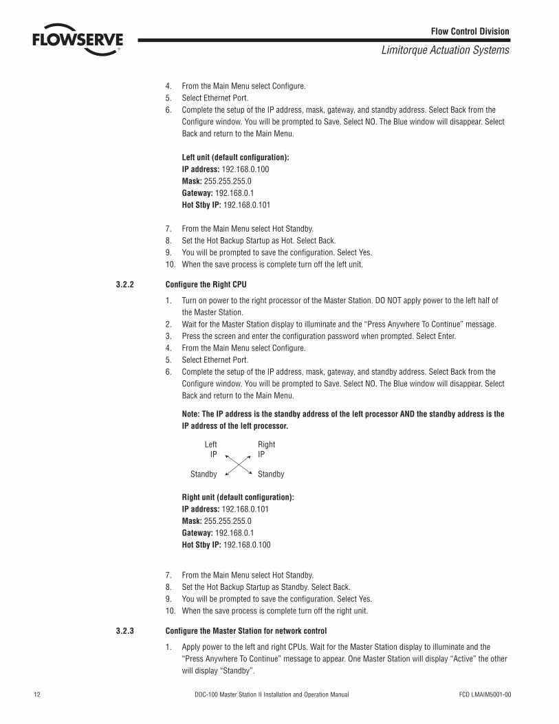
Note: The IP address is the standby address of the left processor AND the standby address is theIP address of the left processor.
Right unit (default configuration):IP address: 192.168.0.101Mask: 255.255.255.0Gateway: 192.168.0.1Hot Stby IP: 192.168.0.100
7. From the Main Menu select Hot Standby.8. Set the Hot Backup Startup as Standby. Select Back.9. You will be prompted to save the configuration. Select Yes.10. When the save process is complete turn off the right unit.
3.2.3 Configure the Master Station for network control
1. Apply power to the left and right CPUs. Wait for the Master Station display to illuminate and the“Press Anywhere To Continue” message to appear. One Master Station will display “Active” the otherwill display “Standby”.
Left Right IP IP
Standby Standby
FCD LMAIM5001-00 DDC-100 Master Station II Installation and Operation Manual 13
Flow Control Division
Limitorque Actuation Systems
2. Press the screen of the ACTIVE Master Station and enter the configure password when prompted.Select Enter.
3. From the Main Menu, select Configure4. Next select Configure the MOV network. Select the network baud rate, Time-out, retries, adjust the
Propagation delay and RTS ON delay if required. Next activate the number of networked MOVs bymaking the button beside the address green.
5. Select the Back button until the Configuration screen is displayed.6. Configure the data tables for the Master Station.
a. To create the Holding register data table (40000 register block for MOV status) for the MasterStation, select Modbus Fc 03. Select the MOV registers to be available for the DCS by pressingthe toggle switch to illuminate the “green light” on the switch. Save the changes and return tothe “Configure DCS Data Table screen.”
b. To create the Coils data table (0000 register block for forcing and reading coils) for the MasterStation, select Modbus Fc 05/15. Select the MOV Coils to be available for the DCS by pressingthe toggle switch to illuminate the “green light” on the switch. Save the changes and return tothe “Configure DCS Data Table” screen. Note this feature also creates the Modbus Fc 01 (ReadCoils) data table.
c. To create the Holding register data table (45000 register block for writing holding registers) forthe Master Station, select Modbus Fc 06/16. Select the number of write registers for the MOVsto be available for the DCS by pressing the toggle switch to illuminate the “green light” on theswitch. Save the changes and return to the “Configure DCS Data Table screen.”
7. Select Back until reaching the “Configure” screen. Select Back and when prompted to Save, select Yes.
Note: All network configuration data, MOV data, and Master Station Data table configurationparameters will be automatically saved to the standby Master Station.
DCS Port configuration data will not be saved as these ports are independently configured.
Items NOT saved to the Standby Master Station:
DCS AddressDCS Baud RateDCS Electrical StandardDCS Stop bitsDCS ParityDCS RTS On DelayDCS RTS Off DelayDCS Startup (Hot or Standby)IP AddressIP MaskGatewayStandby IP Address
8. This will permit a rapid configuration of the Master Station. Further adjustments may be made byfollowing the procedures outlined in the Master Station Manual.

14 DDC-100 Master Station II Installation and Operation Manual FCD LMAIM5001-00
Flow Control Division
Limitorque Actuation Systems
This page is intentionally blank.
FCD LMAIM5001-00 DDC-100 Master Station II Installation and Operation Manual 15
Flow Control Division
Limitorque Actuation Systems
4 Connections
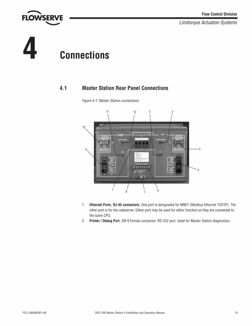
4.1 Master Station Rear Panel Connections
Figure 4-1: Master Station connections
1. Ethernet Ports, RJ-45 connectors. One port is designated for MNET (Modbus Ethernet TCP/IP). Theother port is for the webserver. Either port may be used for either function as they are connected tothe same CPU.
2. Printer / Debug Port. DB-9 Female connector. RS-232 port. Used for Master Station diagnostics.
12
1
11
10
9
8 7 6
2
4
5
3
16 DDC-100 Master Station II Installation and Operation Manual FCD LMAIM5001-00
Flow Control Division
Limitorque Actuation Systems
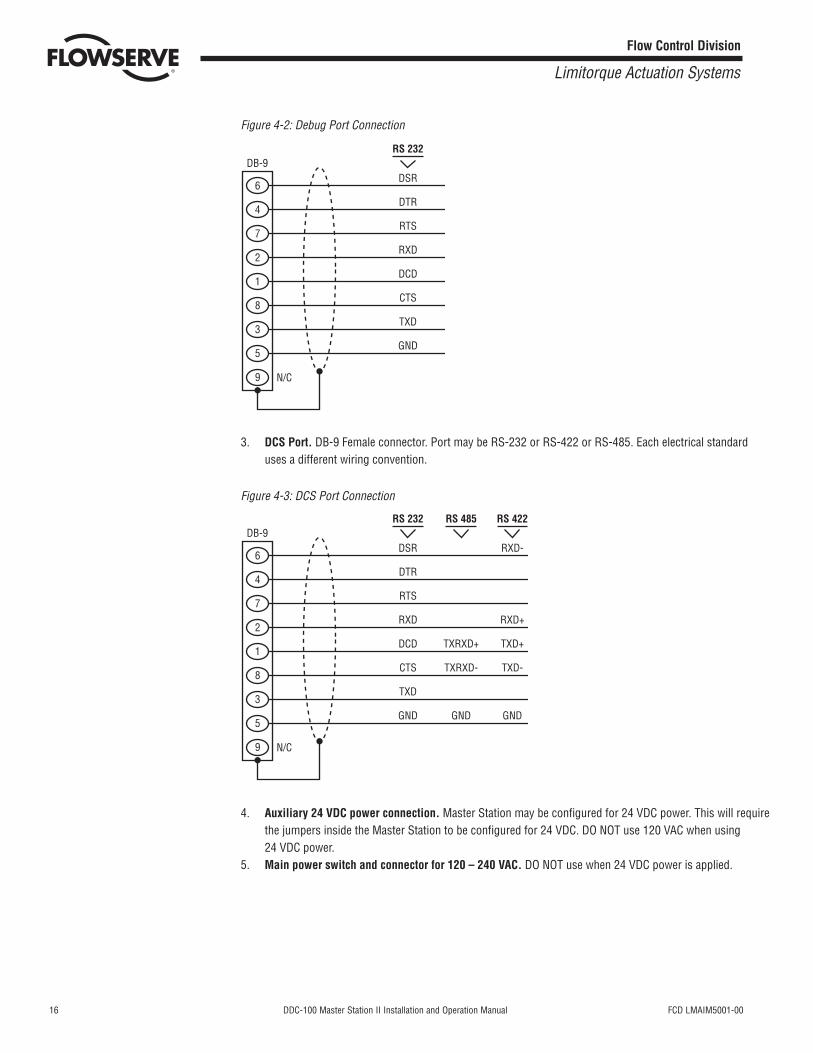
Figure 4-2: Debug Port Connection
3. DCS Port. DB-9 Female connector. Port may be RS-232 or RS-422 or RS-485. Each electrical standarduses a different wiring convention.
Figure 4-3: DCS Port Connection
4. Auxiliary 24 VDC power connection. Master Station may be configured for 24 VDC power. This will requirethe jumpers inside the Master Station to be configured for 24 VDC. DO NOT use 120 VAC when using24 VDC power.
5. Main power switch and connector for 120 – 240 VAC. DO NOT use when 24 VDC power is applied.
9
5
3
8
1
2
7
4
6DSR
DTR
RTS
RXD
DCD
CTS
DB-9RS 232
TXD
GND
N/C
TXRXD+
TXRXD-
RS 485
GND
RXD-
RXD+
TXD+
TXD-
RS 422
GND
9
5
3
8
1
2
7
4
6DSR
DTR
RTS
RXD
DCD
CTS
DB-9RS 232
TXD
GND
N/C
FCD LMAIM5001-00 DDC-100 Master Station II Installation and Operation Manual 17
Flow Control Division
Limitorque Actuation Systems
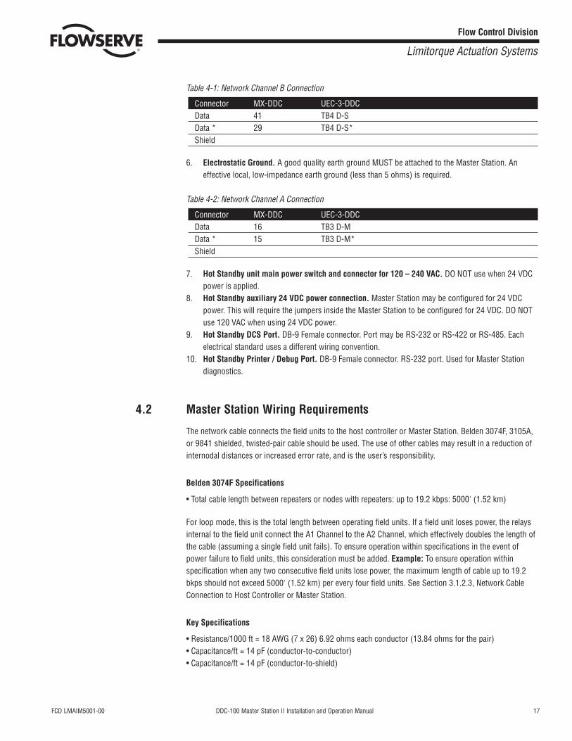
Table 4-1: Network Channel B Connection
Connector MX-DDC UEC-3-DDCData 41 TB4 D-SData * 29 TB4 D-S*Shield
6. Electrostatic Ground. A good quality earth ground MUST be attached to the Master Station. Aneffective local, low-impedance earth ground (less than 5 ohms) is required.
Table 4-2: Network Channel A Connection
Connector MX-DDC UEC-3-DDCData 16 TB3 D-MData * 15 TB3 D-M*Shield
7. Hot Standby unit main power switch and connector for 120 – 240 VAC. DO NOT use when 24 VDCpower is applied.
8. Hot Standby auxiliary 24 VDC power connection. Master Station may be configured for 24 VDCpower. This will require the jumpers inside the Master Station to be configured for 24 VDC. DO NOTuse 120 VAC when using 24 VDC power.
9. Hot Standby DCS Port. DB-9 Female connector. Port may be RS-232 or RS-422 or RS-485. Eachelectrical standard uses a different wiring convention.
10. Hot Standby Printer / Debug Port. DB-9 Female connector. RS-232 port. Used for Master Stationdiagnostics.
4.2 Master Station Wiring Requirements
The network cable connects the field units to the host controller or Master Station. Belden 3074F, 3105A,or 9841 shielded, twisted-pair cable should be used. The use of other cables may result in a reduction ofinternodal distances or increased error rate, and is the user’s responsibility.
Belden 3074F Specifications
• Total cable length between repeaters or nodes with repeaters: up to 19.2 kbps: 5000' (1.52 km)
For loop mode, this is the total length between operating field units. If a field unit loses power, the relaysinternal to the field unit connect the A1 Channel to the A2 Channel, which effectively doubles the length ofthe cable (assuming a single field unit fails). To ensure operation within specifications in the event ofpower failure to field units, this consideration must be added. Example: To ensure operation withinspecification when any two consecutive field units lose power, the maximum length of cable up to 19.2bkps should not exceed 5000' (1.52 km) per every four field units. See Section 3.1.2.3, Network CableConnection to Host Controller or Master Station.
Key Specifications
• Resistance/1000 ft = 18 AWG (7 x 26) 6.92 ohms each conductor (13.84 ohms for the pair)• Capacitance/ft = 14 pF (conductor-to-conductor)• Capacitance/ft = 14 pF (conductor-to-shield)
18 DDC-100 Master Station II Installation and Operation Manual FCD LMAIM5001-00
Flow Control Division
Limitorque Actuation Systems
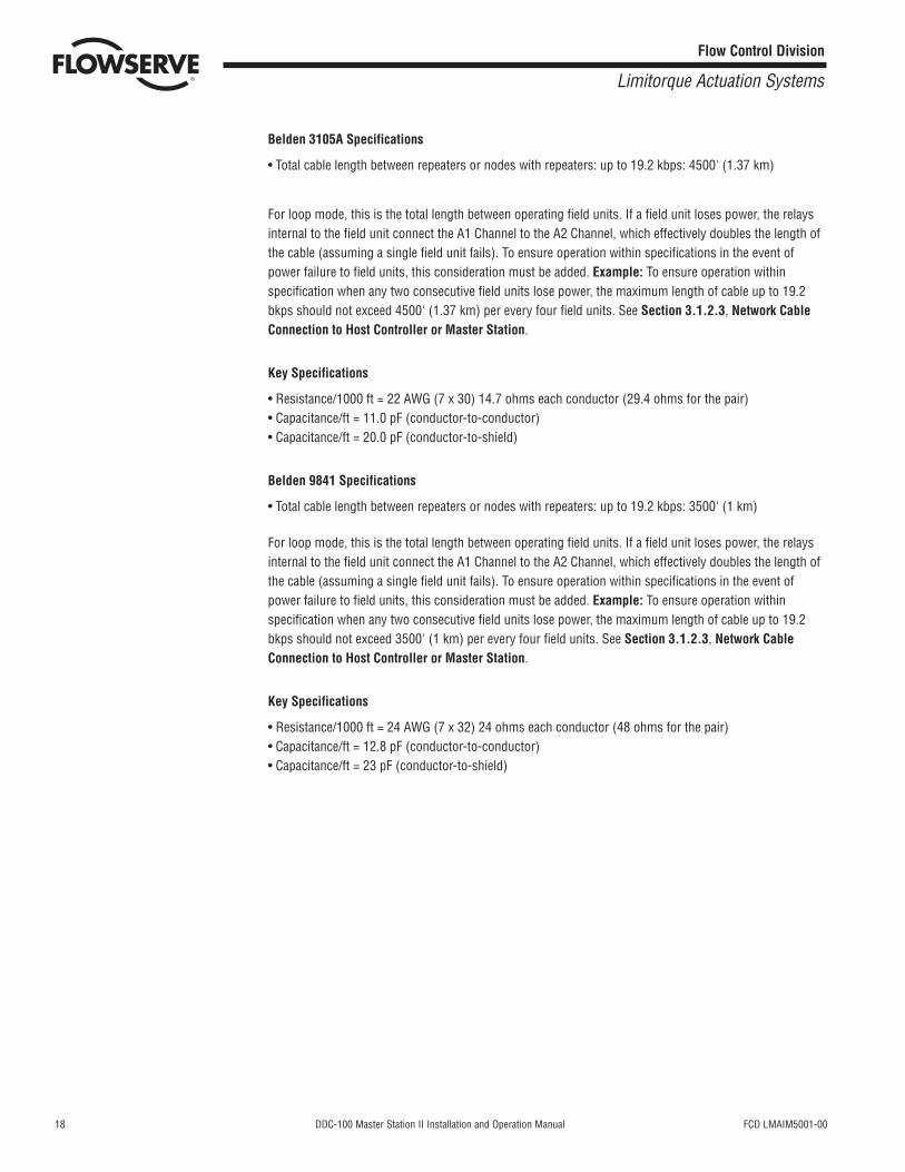
Belden 3105A Specifications
• Total cable length between repeaters or nodes with repeaters: up to 19.2 kbps: 4500' (1.37 km)
For loop mode, this is the total length between operating field units. If a field unit loses power, the relaysinternal to the field unit connect the A1 Channel to the A2 Channel, which effectively doubles the length ofthe cable (assuming a single field unit fails). To ensure operation within specifications in the event ofpower failure to field units, this consideration must be added. Example: To ensure operation withinspecification when any two consecutive field units lose power, the maximum length of cable up to 19.2bkps should not exceed 4500' (1.37 km) per every four field units. See Section 3.1.2.3, Network CableConnection to Host Controller or Master Station.
Key Specifications
• Resistance/1000 ft = 22 AWG (7 x 30) 14.7 ohms each conductor (29.4 ohms for the pair)• Capacitance/ft = 11.0 pF (conductor-to-conductor)• Capacitance/ft = 20.0 pF (conductor-to-shield)
Belden 9841 Specifications
• Total cable length between repeaters or nodes with repeaters: up to 19.2 kbps: 3500' (1 km)
For loop mode, this is the total length between operating field units. If a field unit loses power, the relaysinternal to the field unit connect the A1 Channel to the A2 Channel, which effectively doubles the length ofthe cable (assuming a single field unit fails). To ensure operation within specifications in the event ofpower failure to field units, this consideration must be added. Example: To ensure operation withinspecification when any two consecutive field units lose power, the maximum length of cable up to 19.2bkps should not exceed 3500' (1 km) per every four field units. See Section 3.1.2.3, Network CableConnection to Host Controller or Master Station.
Key Specifications
• Resistance/1000 ft = 24 AWG (7 x 32) 24 ohms each conductor (48 ohms for the pair)• Capacitance/ft = 12.8 pF (conductor-to-conductor)• Capacitance/ft = 23 pF (conductor-to-shield)
FCD LMAIM5001-00 DDC-100 Master Station II Installation and Operation Manual 19
Flow Control Division
Limitorque Actuation Systems
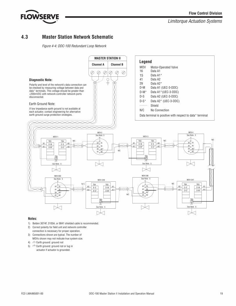
4.3 Master Station Network Schematic
Figure 4-4: DDC-100 Redundant Loop Network
Diagnostic Note:
Earth Ground Note:
MOV-3
A2
A2*
A1
A1*
TB5
MOV-247
A1
A1*
A2
A2*
TB5
N/ C
MOV-249
D-M
D-M*
D-S
D-S*
A1
A1*
A2
A2*
TB4 TB3
TB5
Notes:
LegendMOV
D-MD-M*D-SD-S*
N/C
Data terminal is positive with respect to data* terminal
See Note 5
See Note 5 See Note 5
1) Belden 3074F, 3105A, or 9841 shielded cable is recommended.2) Correct polarity for field unit and network controller
connection is necessary for proper operation.3) Connections shown are typical. The number of
MOVs shown may not indicate true system size.4) Earth ground: ground rod5) Earth ground: ground rod or lug in
actuator if actuator is grounded.
Polarity and level of the network’s data connection canbe checked by measuring voltage between data anddata* terminals. This voltage should be greater than+200mVDC with network controller network portsdisconnected.
If low impedance earth ground is not available ateach actuator, contact engineering for alternativeearth ground surge protection strategies.
A1*
MOV-2See Note 5
N/C
A2*N/C
MOV-248See Note 5
N/C
MOV-4See Note 5
N/C
16154129
2941
D-SD-S*
D-MD-M*
TB3 TB4
MOV-1
A2
A2*
A1
A1*
TB5
See Note 5
D-SD-S*
D-MD-M*
TB3 TB4
D-M
D-M*
D-S
D-S*
TB4 TB3
15
16
A2
A1
A1*
A2*2941
15
16
A2
A1
A1*
A2*2941
15
16
A2
A1
Motor-Operated ValveData A1Data A1*Data A2Data A2*Data A1 (UEC-3-DDC)Data A1*(UEC-3-DDC)
Data A2* (UEC-3-DDC)ShieldNo Connection
Data A2 (UEC-3-DDC)
N/C
MOV-250See Note 5
A1*
A2*2941
15
16
A2
A1
N/C
Channel A Channel B
MASTER STATION II

20 DDC-100 Master Station II Installation and Operation Manual FCD LMAIM5001-00
Flow Control Division
Limitorque Actuation Systems
This page is intentionally blank.
FCD LMAIM5001-00 DDC-100 Master Station II Installation and Operation Manual 21
Flow Control Division
Limitorque Actuation Systems
5 Configuration
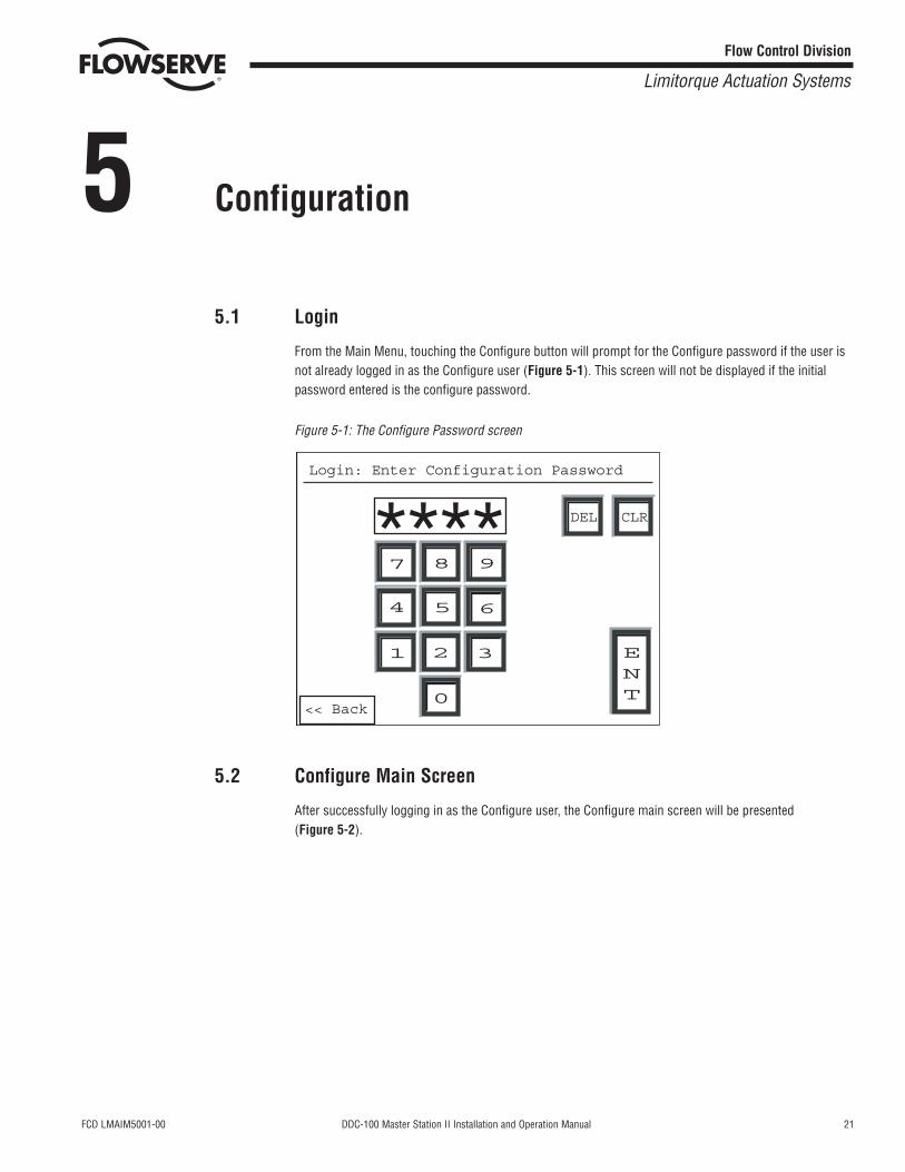
5.1 Login
From the Main Menu, touching the Configure button will prompt for the Configure password if the user isnot already logged in as the Configure user (Figure 5-1). This screen will not be displayed if the initialpassword entered is the configure password.
Figure 5-1: The Configure Password screen
5.2 Configure Main Screen
After successfully logging in as the Configure user, the Configure main screen will be presented(Figure 5-2).
7 8 9
654
1 2 3
0
DEL CLR
ENT
<< Back
Login: Enter Configuration Password
****
22 DDC-100 Master Station II Installation and Operation Manual FCD LMAIM5001-00
Flow Control Division
Limitorque Actuation Systems
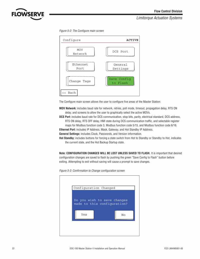
Figure 5-2: The Configure main screen
The Configure main screen allows the user to configure five areas of the Master Station:
MOV Network: includes baud rate for network, retries, poll mode, timeout, propagation delay, RTS ONdelay, and screens to allow the user to graphically select the active MOVs.
DCS Port: includes baud rate for DCS communication, stop bits, parity, electrical standard, DCS address,RTS ON delay, RTS OFF delay, HMI state during DCS communication traffic, and selectable registermaps for Modbus function code 3, Modbus function code 5/15, and Modbus function code 6/16.
Ethernet Port: includes IP Address, Mask, Gateway, and Hot Standby IP Address.General Settings: includes Clock, Passwords, and Version information.Hot Standby: includes buttons for forcing a state switch from Hot to Standby or Standby to Hot, indicates
the current state, and the Hot Backup Startup state.
Note: CONFIGURATION CHANGES WILL BE LOST UNLESS SAVED TO FLASH. It is important that desiredconfiguration changes are saved to flash by pushing the green “Save Config to Flash” button beforeexiting. Attempting to exit without saving will cause a prompt to save changes.
Figure 5-3: Confirmation to Change configuration screen
Yes No
Do you wish to save changes made to this configuration?
Configuration Changed
MOVNetwork
DCS Port
EthernetPort
GeneralSettings
Change TagsSave Configto Flash
Configure ACTIVE
<< Back
FCD LMAIM5001-00 DDC-100 Master Station II Installation and Operation Manual 23
Flow Control Division
Limitorque Actuation Systems
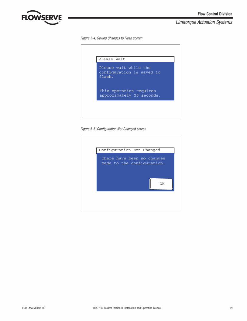
Figure 5-4: Saving Changes to Flash screen
Figure 5-5: Configuration Not Changed screen
OK
There have been no changesmade to the configuration.
Configuration Not Changed
Please wait while the configuration is saved to flash.
This operation requiresapproximately 20 seconds.
Please Wait
24 DDC-100 Master Station II Installation and Operation Manual FCD LMAIM5001-00
Flow Control Division
Limitorque Actuation Systems
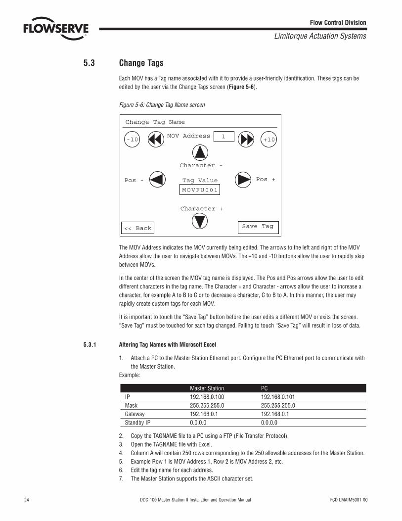
5.3 Change Tags
Each MOV has a Tag name associated with it to provide a user-friendly identification. These tags can beedited by the user via the Change Tags screen (Figure 5-6).
Figure 5-6: Change Tag Name screen
The MOV Address indicates the MOV currently being edited. The arrows to the left and right of the MOVAddress allow the user to navigate between MOVs. The +10 and -10 buttons allow the user to rapidly skipbetween MOVs.
In the center of the screen the MOV tag name is displayed. The Pos and Pos arrows allow the user to editdifferent characters in the tag name. The Character + and Character - arrows allow the user to increase acharacter, for example A to B to C or to decrease a character, C to B to A. In this manner, the user mayrapidly create custom tags for each MOV.
It is important to touch the “Save Tag” button before the user edits a different MOV or exits the screen.“Save Tag” must be touched for each tag changed. Failing to touch “Save Tag” will result in loss of data.
5.3.1 Altering Tag Names with Microsoft Excel
1. Attach a PC to the Master Station Ethernet port. Configure the PC Ethernet port to communicate withthe Master Station.
Example:
Master Station PCIP 192.168.0.100 192.168.0.101Mask 255.255.255.0 255.255.255.0Gateway 192.168.0.1 192.168.0.1Standby IP 0.0.0.0 0.0.0.0
2. Copy the TAGNAME file to a PC using a FTP (File Transfer Protocol).3. Open the TAGNAME file with Excel.4. Column A will contain 250 rows corresponding to the 250 allowable addresses for the Master Station.5. Example Row 1 is MOV Address 1, Row 2 is MOV Address 2, etc.6. Edit the tag name for each address. 7. The Master Station supports the ASCII character set.
Change Tag Name
MOV Address
Character -
Tag Value
MOVFU001
Character +
Pos - Pos +
<< Back Save Tag
1-10 +10
FCD LMAIM5001-00 DDC-100 Master Station II Installation and Operation Manual 25
Flow Control Division
Limitorque Actuation Systems
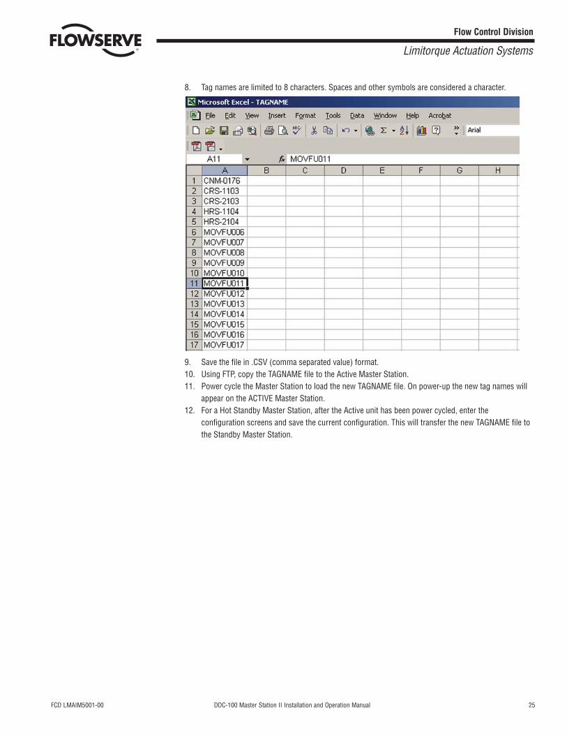
8. Tag names are limited to 8 characters. Spaces and other symbols are considered a character.
9. Save the file in .CSV (comma separated value) format.10. Using FTP, copy the TAGNAME file to the Active Master Station.11. Power cycle the Master Station to load the new TAGNAME file. On power-up the new tag names will
appear on the ACTIVE Master Station.12. For a Hot Standby Master Station, after the Active unit has been power cycled, enter the
configuration screens and save the current configuration. This will transfer the new TAGNAME file tothe Standby Master Station.

26 DDC-100 Master Station II Installation and Operation Manual FCD LMAIM5001-00
Flow Control Division
Limitorque Actuation Systems
This page is intentionally blank.
FCD LMAIM5001-00 DDC-100 Master Station II Installation and Operation Manual 27
Flow Control Division
Limitorque Actuation Systems
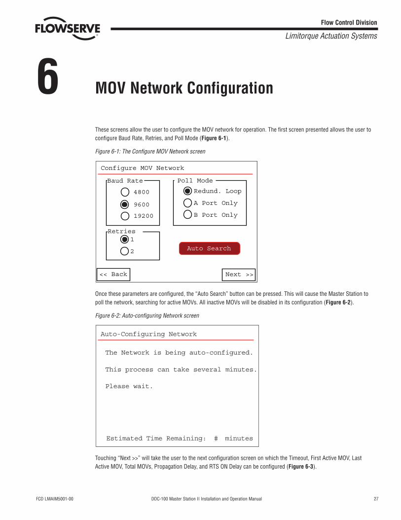
6 MOV Network Configuration
These screens allow the user to configure the MOV network for operation. The first screen presented allows the user toconfigure Baud Rate, Retries, and Poll Mode (Figure 6-1).
Figure 6-1: The Configure MOV Network screen
Once these parameters are configured, the “Auto Search” button can be pressed. This will cause the Master Station topoll the network, searching for active MOVs. All inactive MOVs will be disabled in its configuration (Figure 6-2).
Figure 6-2: Auto-configuring Network screen
Touching “Next >>” will take the user to the next configuration screen on which the Timeout, First Active MOV, LastActive MOV, Total MOVs, Propagation Delay, and RTS ON Delay can be configured (Figure 6-3).
Auto-Configuring Network
The Network is being auto-configured.
This process can take several minutes.
Please wait.
Estimated Time Remaining: # minutes
Baud Rate
4800
9600
19200
Retries1
2
Redund. Loop
A Port Only
B Port Only
Configure MOV Network
Poll Mode
<< Back Next >>
Auto Search
28 DDC-100 Master Station II Installation and Operation Manual FCD LMAIM5001-00
Flow Control Division
Limitorque Actuation Systems
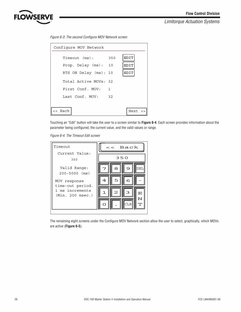
Figure 6-3: The second Configure MOV Network screen
Touching an “Edit” button will take the user to a screen similar to Figure 6-4. Each screen provides information about theparameter being configured, the current value, and the valid values or range.
Figure 6-4: The Timeout Edit screen
The remaining eight screens under the Configure MOV Network section allow the user to select, graphically, which MOVsare active (Figure 6-5).
Timeout
Current Value:
350
200-5000 (ms)
Valid Range:
MOV responsetime-out period.1 ms increments(Min. 200 msec.)
350
<< Back
7 8 9
654
1 2 3
0 . CLR
DEL
-
ENT
EDITEDIT
EDITEDIT
EDITEDIT
Timeout (ms): 350
Prop. Delay (ms): 10
RTS ON Delay (ms): 10
Total Active MOVs: 32
First Conf. MOV: 1
Last Conf. MOV: 32
Configure MOV Network
<< Back Next >>
FCD LMAIM5001-00 DDC-100 Master Station II Installation and Operation Manual 29
Flow Control Division
Limitorque Actuation Systems
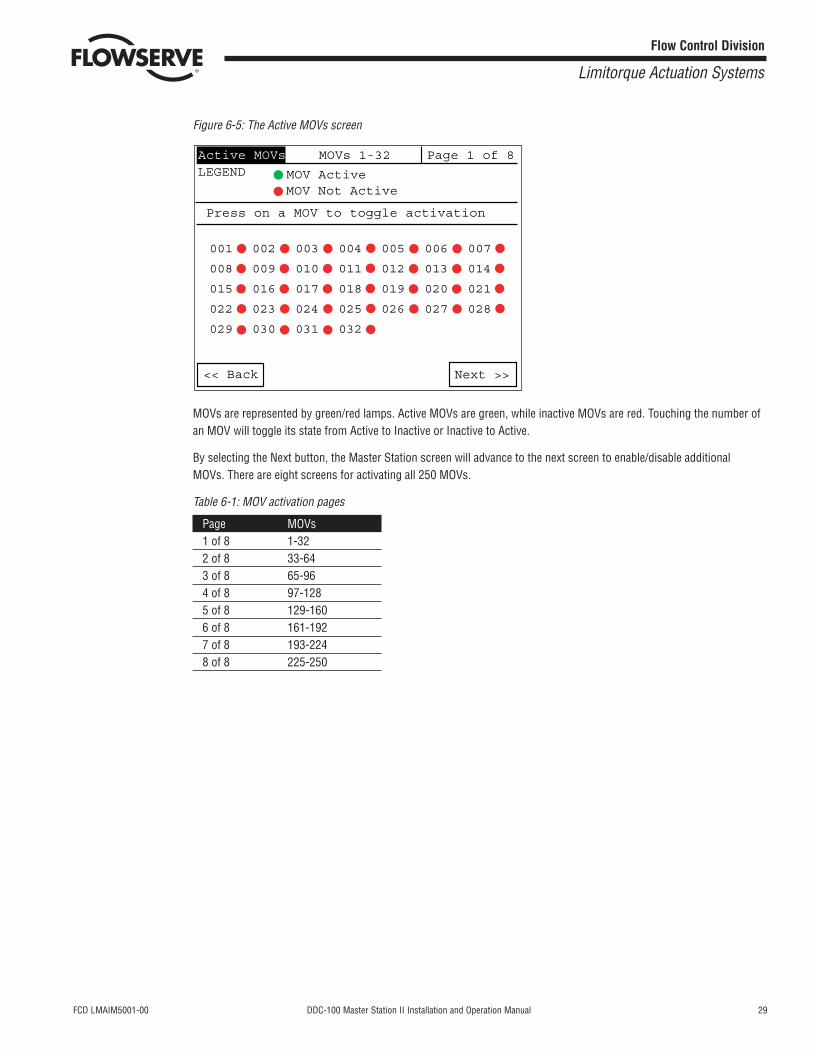
Figure 6-5: The Active MOVs screen
MOVs are represented by green/red lamps. Active MOVs are green, while inactive MOVs are red. Touching the number ofan MOV will toggle its state from Active to Inactive or Inactive to Active.
By selecting the Next button, the Master Station screen will advance to the next screen to enable/disable additionalMOVs. There are eight screens for activating all 250 MOVs.
Table 6-1: MOV activation pages
Page MOVs1 of 8 1-322 of 8 33-643 of 8 65-964 of 8 97-1285 of 8 129-1606 of 8 161-1927 of 8 193-2248 of 8 225-250
Next >><< Back
001 002 003 004 005 006 007
008 009 010 011 012 013 014
015 016 017 018 019 020 021
022 023 024 025 026 027 028
029 030 031 032
Press on a MOV to toggle activation
MOV Not ActiveMOV ActiveLEGEND
Active MOVs MOVs 1-32 Page 1 of 8

30 DDC-100 Master Station II Installation and Operation Manual FCD LMAIM5001-00
Flow Control Division
Limitorque Actuation Systems
This page is intentionally blank.
FCD LMAIM5001-00 DDC-100 Master Station II Installation and Operation Manual 31
Flow Control Division
Limitorque Actuation Systems
7 DCS Port Configuration
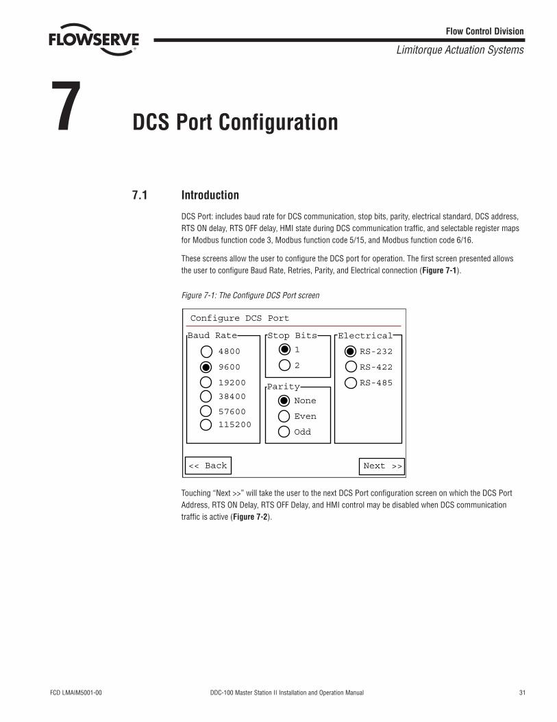
7.1 Introduction
DCS Port: includes baud rate for DCS communication, stop bits, parity, electrical standard, DCS address,RTS ON delay, RTS OFF delay, HMI state during DCS communication traffic, and selectable register mapsfor Modbus function code 3, Modbus function code 5/15, and Modbus function code 6/16.
These screens allow the user to configure the DCS port for operation. The first screen presented allowsthe user to configure Baud Rate, Retries, Parity, and Electrical connection (Figure 7-1).
Figure 7-1: The Configure DCS Port screen
Touching “Next >>” will take the user to the next DCS Port configuration screen on which the DCS PortAddress, RTS ON Delay, RTS OFF Delay, and HMI control may be disabled when DCS communicationtraffic is active (Figure 7-2).
Configure DCS Port
Baud Rate Stop Bits Electrical
1
2
RS-232
RS-422
RS-485
None
Even
Odd
Parity
4800
9600
19200
38400
57600
115200
<< Back Next >>
32 DDC-100 Master Station II Installation and Operation Manual FCD LMAIM5001-00
Flow Control Division
Limitorque Actuation Systems
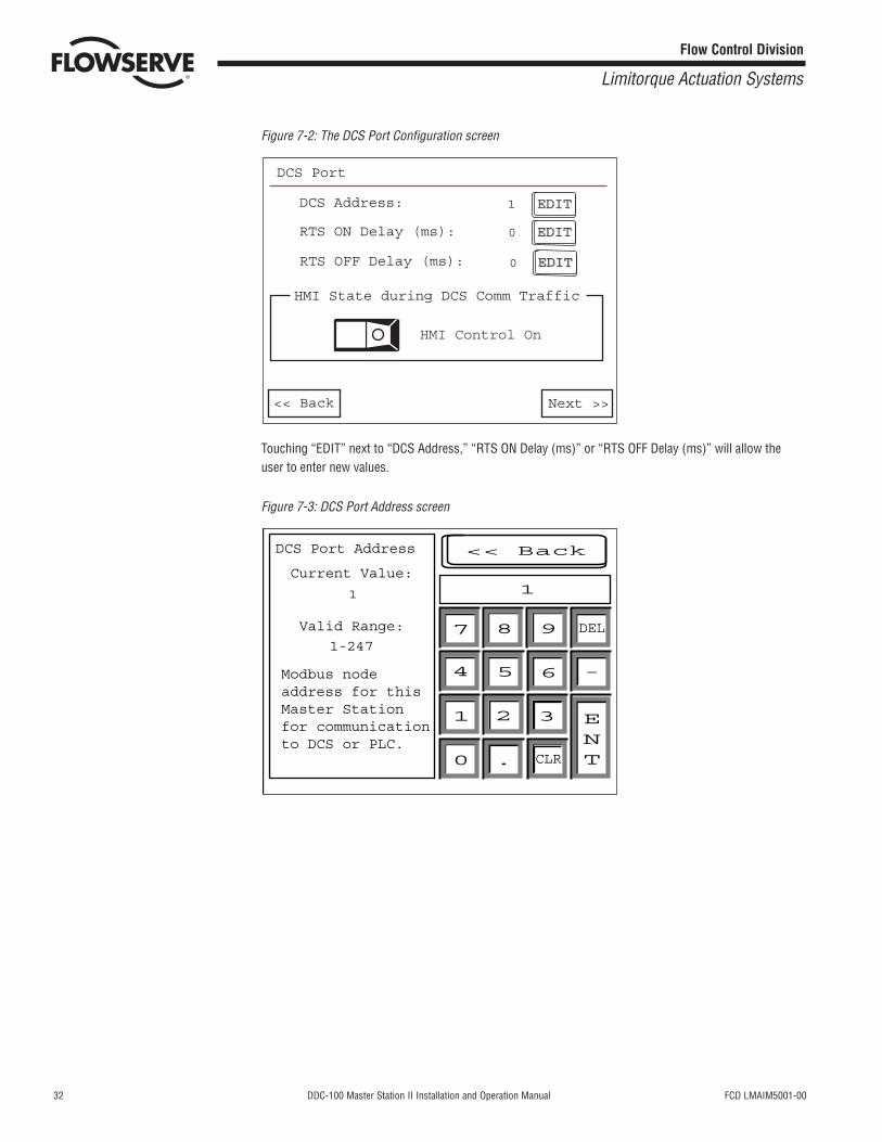
Figure 7-2: The DCS Port Configuration screen
Touching “EDIT” next to “DCS Address,” “RTS ON Delay (ms)” or “RTS OFF Delay (ms)” will allow theuser to enter new values.
Figure 7-3: DCS Port Address screen
DCS Port Address
Current Value:
1
1-247
Valid Range:
Modbus nodeaddress for thisMaster Stationfor communicationto DCS or PLC.
1
<< Back
7 8 9
654
1 2 3
0 . CLR
DEL
-
ENT
EDITEDIT
EDIT
DCS Port
DCS Address:
RTS ON Delay (ms):
RTS OFF Delay (ms): 0
0
1
HMI State during DCS Comm Traffic
HMI Control On
<< Back Next >>
EDITEDIT
EDIT
FCD LMAIM5001-00 DDC-100 Master Station II Installation and Operation Manual 33
Flow Control Division
Limitorque Actuation Systems
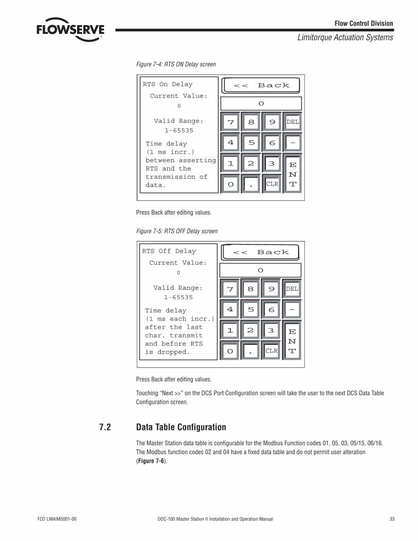
Figure 7-4: RTS ON Delay screen
Press Back after editing values.
Figure 7-5: RTS OFF Delay screen
Press Back after editing values.
Touching “Next >>” on the DCS Port Configuration screen will take the user to the next DCS Data TableConfiguration screen.
7.2 Data Table Configuration
The Master Station data table is configurable for the Modbus Function codes 01, 05, 03, 05/15, 06/16.The Modbus function codes 02 and 04 have a fixed data table and do not permit user alteration(Figure 7-6).
RTS Off Delay
Current Value:
0
1-65535Valid Range:
Time delay(1 ms each incr.)after the last char. transmitand before RTSis dropped.
0
<< Back
7 8 9
654
1 2 3
0 . CLR
DEL
-
ENT
RTS On Delay
Current Value:
0
1-65535Valid Range:
Time delay(1 ms incr.)between assertingRTS and thetransmission ofdata.
0
<< Back
7 8 9
654
1 2 3
0 . CLR
DEL
-
ENT
34 DDC-100 Master Station II Installation and Operation Manual FCD LMAIM5001-00
Flow Control Division
Limitorque Actuation Systems
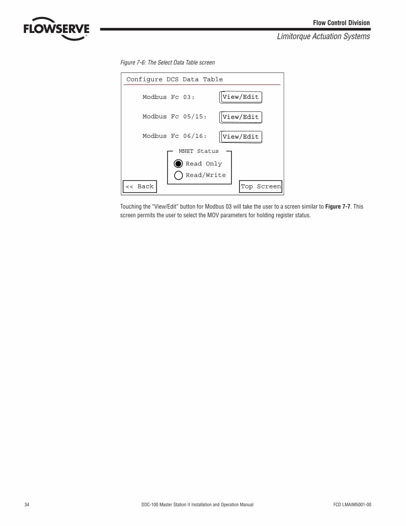
Figure 7-6: The Select Data Table screen
Touching the “View/Edit” button for Modbus 03 will take the user to a screen similar to Figure 7-7. Thisscreen permits the user to select the MOV parameters for holding register status.
<< Back Top Screen
Configure DCS Data Table
View/EditView/Edit
View/EditView/Edit
View/EditView/Edit
Read Only
Read/Write
Modbus Fc 03:
Modbus Fc 05/15:
Modbus Fc 06/16:
MNET Status
FCD LMAIM5001-00 DDC-100 Master Station II Installation and Operation Manual 35
Flow Control Division
Limitorque Actuation Systems
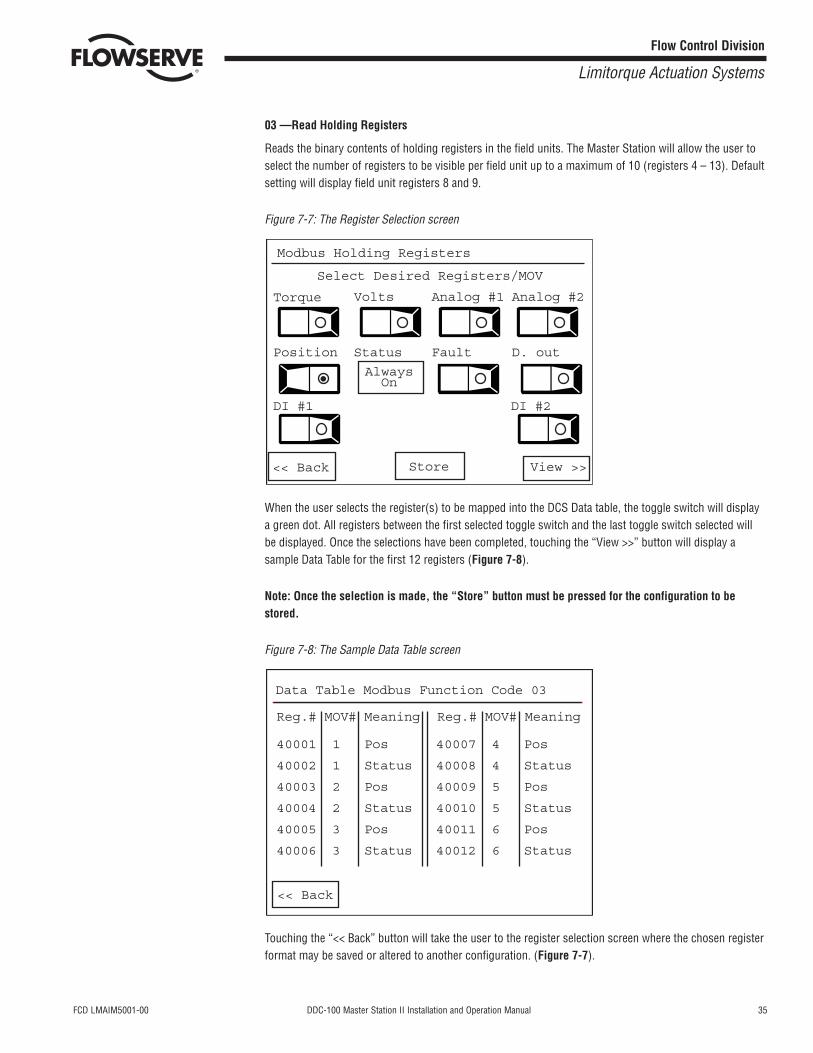
03 —Read Holding Registers
Reads the binary contents of holding registers in the field units. The Master Station will allow the user toselect the number of registers to be visible per field unit up to a maximum of 10 (registers 4 – 13). Defaultsetting will display field unit registers 8 and 9.
Figure 7-7: The Register Selection screen
When the user selects the register(s) to be mapped into the DCS Data table, the toggle switch will displaya green dot. All registers between the first selected toggle switch and the last toggle switch selected willbe displayed. Once the selections have been completed, touching the “View >>” button will display asample Data Table for the first 12 registers (Figure 7-8).
Note: Once the selection is made, the “Store” button must be pressed for the configuration to bestored.
Figure 7-8: The Sample Data Table screen
Touching the “<< Back” button will take the user to the register selection screen where the chosen registerformat may be saved or altered to another configuration. (Figure 7-7).
Data Table Modbus Function Code 03
Reg.# MOV# Meaning
40001 1 Pos
40002 1 Status
40003 2 Pos
40004 2 Status
40005 3 Pos
40006 3 Status
40007 4 Pos
40008 4 Status
40009 5 Pos
40010 5 Status
40011 6 Pos
40012 6 Status
Reg.# MOV# Meaning
<< Back
Modbus Holding Registers
Select Desired Registers/MOV
Torque Volts Analog #1 Analog #2
D. outFaultStatusPosition
DI #1 DI #2
AlwaysOn
Store View >><< Back
36 DDC-100 Master Station II Installation and Operation Manual FCD LMAIM5001-00
Flow Control Division
Limitorque Actuation Systems
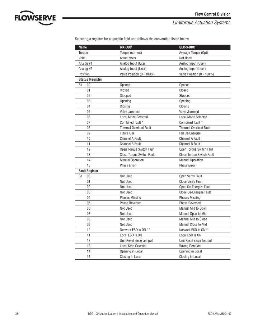
Selecting a register for a specific field unit follows the convention listed below.
Name MX-DDC UEC-3-DDCTorque Torque (current) Average Torque (Opt)Volts Actual Volts Not UsedAnalog #1 Analog Input (User) Analog Input (User)Analog #2 Analog Input (User) Analog Input (User)Position Valve Position (0 - 100%) Valve Position (0 - 100%)Status RegisterBit 00 Opened Opened
01 Closed Closed02 Stopped Stopped03 Opening Opening04 Closing Closing05 Valve Jammed Valve Jammed06 Local Mode Selected Local Mode Selected07 Combined Fault * Combined Fault *08 Thermal Overload Fault Thermal Overload Fault09 Future Use Fail De-Energize10 Channel A Fault Channel A Fault11 Channel B Fault Channel B Fault12 Open Torque Switch Fault Open Torque Switch Faul13 Close Torque Switch Fault Close Torque Switch Fault14 Manual Operation Manual Operation15 Phase Error Phase Error
Fault RegisterBit 00 Not Used Open Verify Fault
01 Not Used Close Verify Fault02 Not Used Open De-Energize Fault03 Not Used Close De-Energize Fault04 Phases Missing Phases Missing05 Phase Reversed Phase Reversed06 Not Used Manual Mid to Open07 Not Used Manual Open to Mid08 Not Used Manual Mid to Close09 Not Used Manual Close to Mid10 Network ESD is ON ** Network ESD is ON**11 Local ESD is ON Local ESD is ON12 Unit Reset since last poll Unit Reset since last poll13 Local Stop Selected Wrong Rotation14 Opening in Local Opening in Local15 Closing in Local Closing in Local
FCD LMAIM5001-00 DDC-100 Master Station II Installation and Operation Manual 37
Flow Control Division
Limitorque Actuation Systems
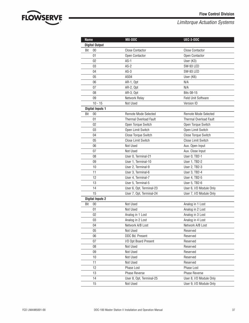
Name MX-DDC UEC-3-DDCDigital OutputBit 00 Close Contactor Close Contactor
01 Open Contactor Open Contactor02 AS-1 User (K3)03 AS-2 SW-93 LED04 AS-3 SW-93 LED05 AS04 User (K6)06 AR-1, Opt N/A07 AR-2, Opt N/A08 AR-3, Opt Bits 08-1509 Network Relay Field Unit Software10 - 15 Not Used Version ID
Digital Inputs 1Bit 00 Remote Mode Selected Remote Mode Selected
01 Thermal Overload Fault Thermal Overload Fault02 Open Torque Switch Open Torque Switch03 Open Limit Switch Open Limit Switch04 Close Torque Switch Close Torque Switch05 Close Limit Switch Close Limit Switch06 Not Used Aux. Open Input07 Not Used Aux. Close Input08 User 0, Terminal-21 User 0, TB2-109 User 1, Terminal-10 User 1, TB2-210 User 2, Terminal-9 User 2, TB2-311 User 3, Terminal-6 User 3, TB2-412 User 4, Terminal-7 User 4, TB2-513 User 5, Terminal-5 User 5, TB2-614 User 6, Opt, Terminal-23 User 6, I/O Module Only15 User 7, Opt, Terminal-24 User 7, I/O Module Only
Digital Inputs 2Bit 00 Not Used Analog in 1 Lost
01 Not Used Analog in 2 Lost02 Analog in 1 Lost Analog in 3 Lost03 Analog in 2 Lost Analog in 4 Lost04 Network A/B Lost Network A/B Lost05 Not Used Reserved06 DDC Bd. Present Reserved07 I/O Opt Board Present Reserved08 Not Used Reserved09 Not Used Reserved10 Not Used Reserved11 Not Used Reserved12 Phase Lost Phase Lost13 Phase Reverse Phase Reverse14 User 8, Opt, Terminal-25 User 8, I/O Module Only15 Not Used User 9, I/O Module Only
38 DDC-100 Master Station II Installation and Operation Manual FCD LMAIM5001-00
Flow Control Division
Limitorque Actuation Systems
DCS Requested Register = [(field unit address –1) * number of registers per unit] + desired register
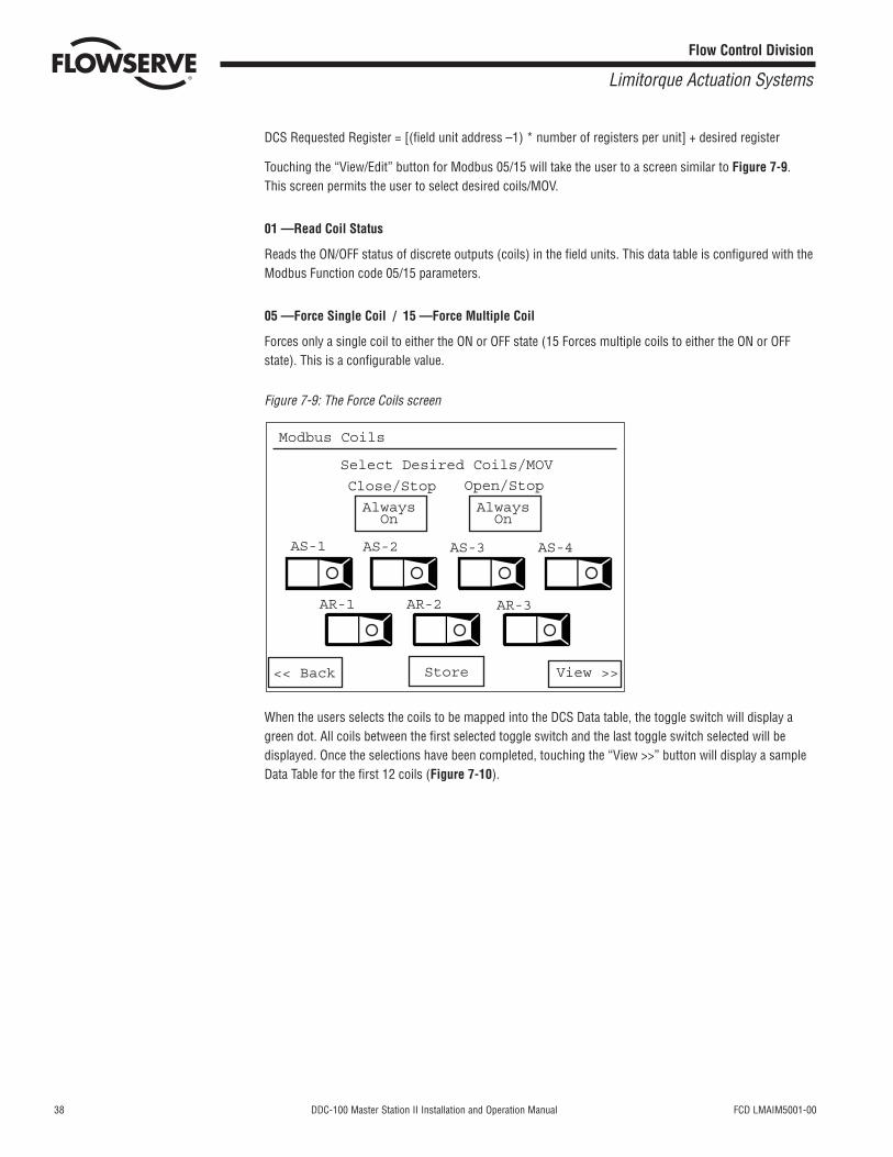
Touching the “View/Edit” button for Modbus 05/15 will take the user to a screen similar to Figure 7-9.This screen permits the user to select desired coils/MOV.
01 —Read Coil Status
Reads the ON/OFF status of discrete outputs (coils) in the field units. This data table is configured with theModbus Function code 05/15 parameters.
05 —Force Single Coil / 15 —Force Multiple Coil
Forces only a single coil to either the ON or OFF state (15 Forces multiple coils to either the ON or OFFstate). This is a configurable value.
Figure 7-9: The Force Coils screen
When the users selects the coils to be mapped into the DCS Data table, the toggle switch will display agreen dot. All coils between the first selected toggle switch and the last toggle switch selected will bedisplayed. Once the selections have been completed, touching the “View >>” button will display a sampleData Table for the first 12 coils (Figure 7-10).
Modbus Coils
AS-1
Close/Stop
Select Desired Coils/MOV
Open/Stop
AS-2 AS-3 AS-4
AR-3AR-2AR-1
Store View >><< Back
AlwaysOn
AlwaysOn
FCD LMAIM5001-00 DDC-100 Master Station II Installation and Operation Manual 39
Flow Control Division
Limitorque Actuation Systems
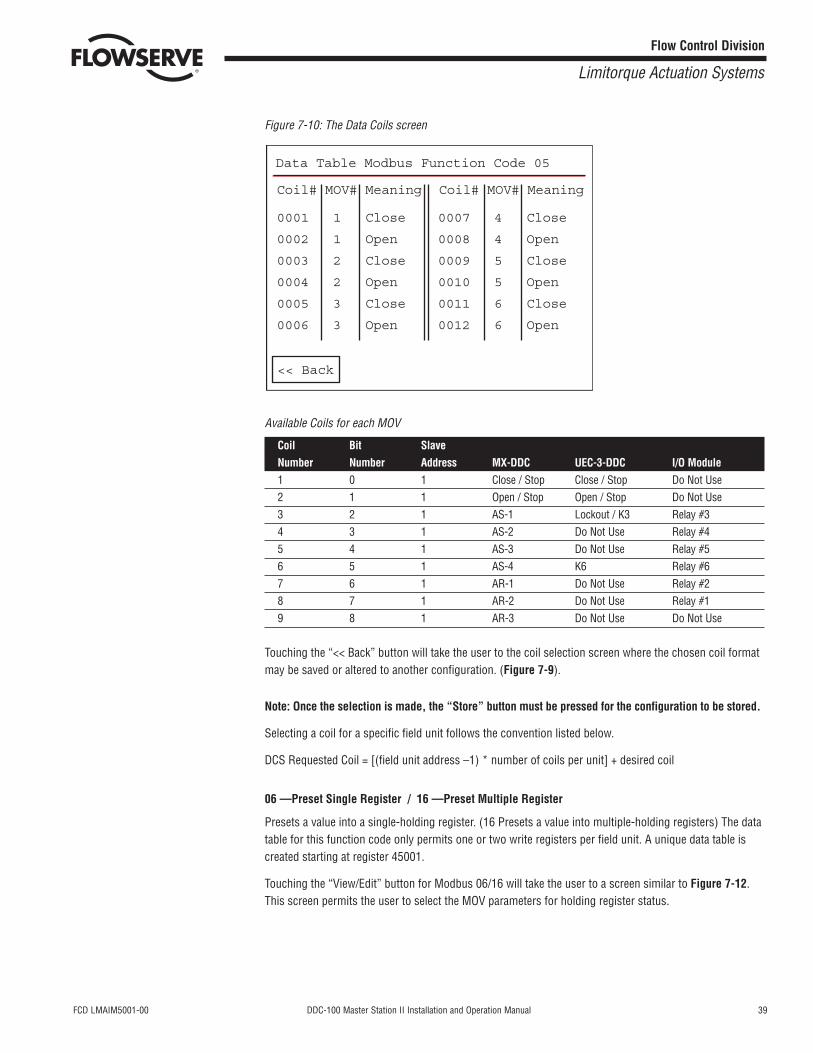
Figure 7-10: The Data Coils screen
Available Coils for each MOV
Coil Bit SlaveNumber Number Address MX-DDC UEC-3-DDC I/O Module1 0 1 Close / Stop Close / Stop Do Not Use2 1 1 Open / Stop Open / Stop Do Not Use3 2 1 AS-1 Lockout / K3 Relay #34 3 1 AS-2 Do Not Use Relay #45 4 1 AS-3 Do Not Use Relay #56 5 1 AS-4 K6 Relay #67 6 1 AR-1 Do Not Use Relay #28 7 1 AR-2 Do Not Use Relay #19 8 1 AR-3 Do Not Use Do Not Use
Touching the “<< Back” button will take the user to the coil selection screen where the chosen coil formatmay be saved or altered to another configuration. (Figure 7-9).
Note: Once the selection is made, the “Store” button must be pressed for the configuration to be stored.
Selecting a coil for a specific field unit follows the convention listed below.
DCS Requested Coil = [(field unit address –1) * number of coils per unit] + desired coil
06 —Preset Single Register / 16 —Preset Multiple Register
Presets a value into a single-holding register. (16 Presets a value into multiple-holding registers) The datatable for this function code only permits one or two write registers per field unit. A unique data table iscreated starting at register 45001.
Touching the “View/Edit” button for Modbus 06/16 will take the user to a screen similar to Figure 7-12.This screen permits the user to select the MOV parameters for holding register status.
Data Table Modbus Function Code 05
Coil# MOV# Meaning
0001 1 Close
0002 1 Open
0003 2 Close
0004 2 Open
0005 3 Close
0006 3 Open
0007 4 Close
0008 4 Open
0009 5 Close
0010 5 Open
0011 6 Close
0012 6 Open
Coil# MOV# Meaning
<< Back
40 DDC-100 Master Station II Installation and Operation Manual FCD LMAIM5001-00
Flow Control Division
Limitorque Actuation Systems
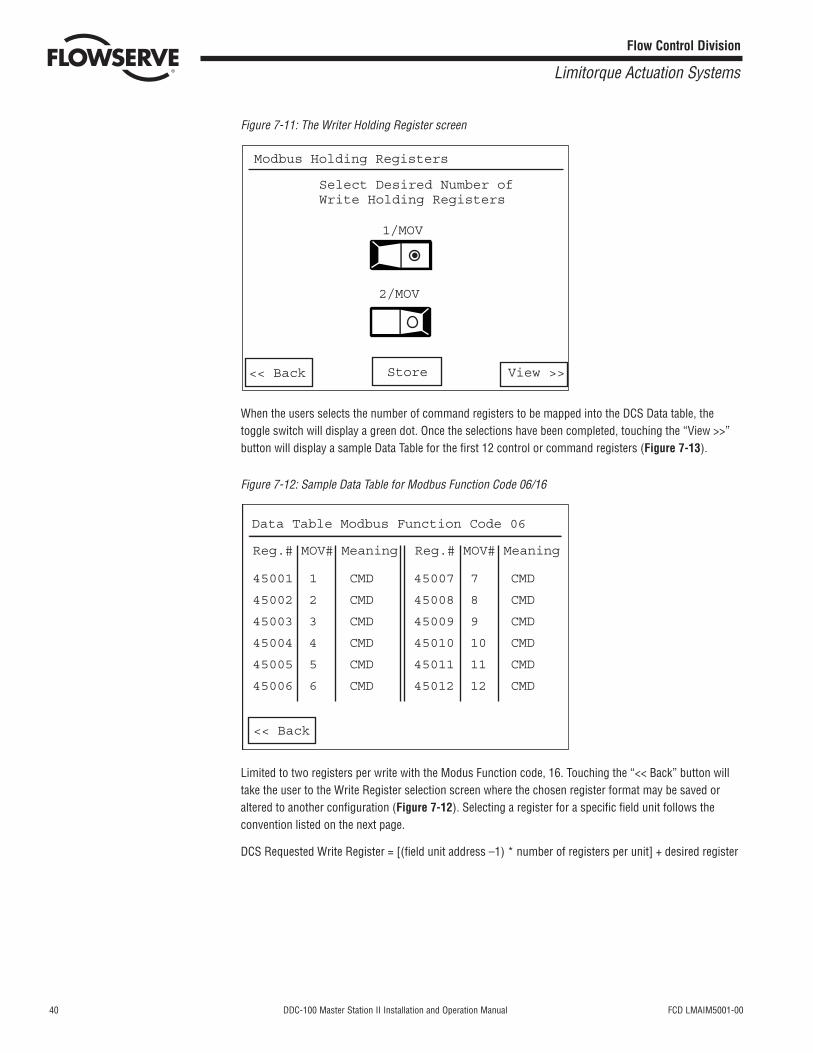
Figure 7-11: The Writer Holding Register screen
When the users selects the number of command registers to be mapped into the DCS Data table, thetoggle switch will display a green dot. Once the selections have been completed, touching the “View >>”button will display a sample Data Table for the first 12 control or command registers (Figure 7-13).
Figure 7-12: Sample Data Table for Modbus Function Code 06/16
Limited to two registers per write with the Modus Function code, 16. Touching the “<< Back” button willtake the user to the Write Register selection screen where the chosen register format may be saved oraltered to another configuration (Figure 7-12). Selecting a register for a specific field unit follows theconvention listed on the next page.
DCS Requested Write Register = [(field unit address –1) * number of registers per unit] + desired register
Data Table Modbus Function Code 06
Reg.# MOV# Meaning
45001 1 CMD
45002 2 CMD
45003 3 CMD
45004 4 CMD
45005 5 CMD
45006 6 CMD
45007 7 CMD
45008 8 CMD
45009 9 CMD
45010 10 CMD
45011 11 CMD
45012 12 CMD
Reg.# MOV# Meaning
<< Back
Modbus Holding Registers
Select Desired Number ofWrite Holding Registers
1/MOV
2/MOV
Store View >><< Back
FCD LMAIM5001-00 DDC-100 Master Station II Installation and Operation Manual 41
Flow Control Division
Limitorque Actuation Systems
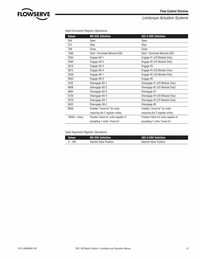
Valid Command Register Operations
Values MX-DDC Definition UEC-3-DDC Definition256 Open Open512 Stop Stop768 Close Close1280 Start / Terminate Network ESD Start / Terminate Network ESD2304 Engage AS-1 Engage #1 (I/O Module Only)2560 Engage AS-2 Engage #2 (I/O Module Only)2816 Engage AS-3 Engage #33072 Engage AS-4 Engage #4 (I/O Module Only)3328 Engage AR-1 Engage #5 (I/O Module Only)3584 Engage AR-2 Engage #64352 Disengage AS-1 Disengage #1 (I/O Module Only)4608 Disengage AS-2 Disengage #2 (I/O Module Only)4864 Disengage AS-3 Disengage #35120 Disengage AS-4 Disengage #4 (I/O Module Only)5376 Disengage AR-1 Disengage #5 (I/O Module Only)5632 Disengage AS-2 Disengage #66656 Enables “move-to” for units Enables “move-to” for units
requiring the 2 register writes. requiring the 2 register writes.19200 + Value Position Value for units capable of Position Valve for units capable of
accepting 1 write “move-to” accepting 1 write “move-to”
Valid Argument Register Operations
Values MX-DDC Definition UEC-3-DDC Definition0 - 100 Desired Valve Position Desired Valve Position
42 DDC-100 Master Station II Installation and Operation Manual FCD LMAIM5001-00
Flow Control Division
Limitorque Actuation Systems
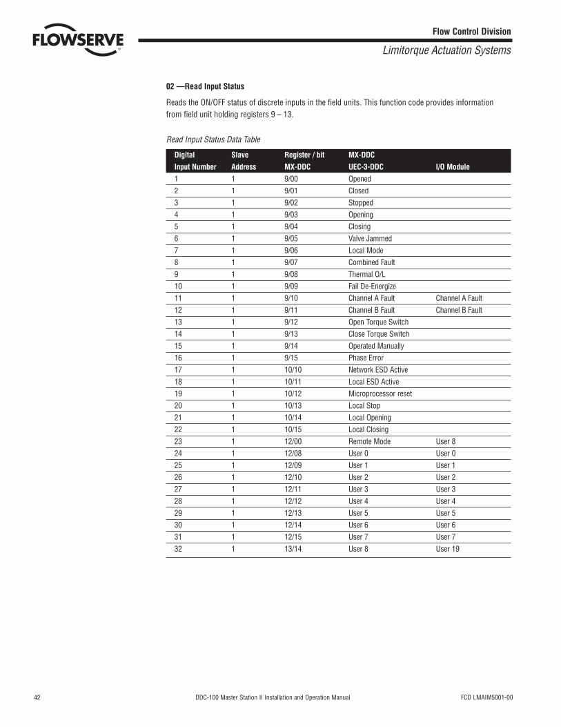
02 —Read Input Status
Reads the ON/OFF status of discrete inputs in the field units. This function code provides informationfrom field unit holding registers 9 – 13.
Read Input Status Data Table
Digital Slave Register / bit MX-DDCInput Number Address MX-DDC UEC-3-DDC I/O Module1 1 9/00 Opened2 1 9/01 Closed3 1 9/02 Stopped4 1 9/03 Opening5 1 9/04 Closing6 1 9/05 Valve Jammed7 1 9/06 Local Mode8 1 9/07 Combined Fault9 1 9/08 Thermal O/L10 1 9/09 Fail De-Energize11 1 9/10 Channel A Fault Channel A Fault12 1 9/11 Channel B Fault Channel B Fault13 1 9/12 Open Torque Switch14 1 9/13 Close Torque Switch15 1 9/14 Operated Manually16 1 9/15 Phase Error17 1 10/10 Network ESD Active18 1 10/11 Local ESD Active19 1 10/12 Microprocessor reset20 1 10/13 Local Stop21 1 10/14 Local Opening22 1 10/15 Local Closing23 1 12/00 Remote Mode User 824 1 12/08 User 0 User 025 1 12/09 User 1 User 126 1 12/10 User 2 User 227 1 12/11 User 3 User 328 1 12/12 User 4 User 429 1 12/13 User 5 User 530 1 12/14 User 6 User 631 1 12/15 User 7 User 732 1 13/14 User 8 User 19
FCD LMAIM5001-00 DDC-100 Master Station II Installation and Operation Manual 43
Flow Control Division
Limitorque Actuation Systems
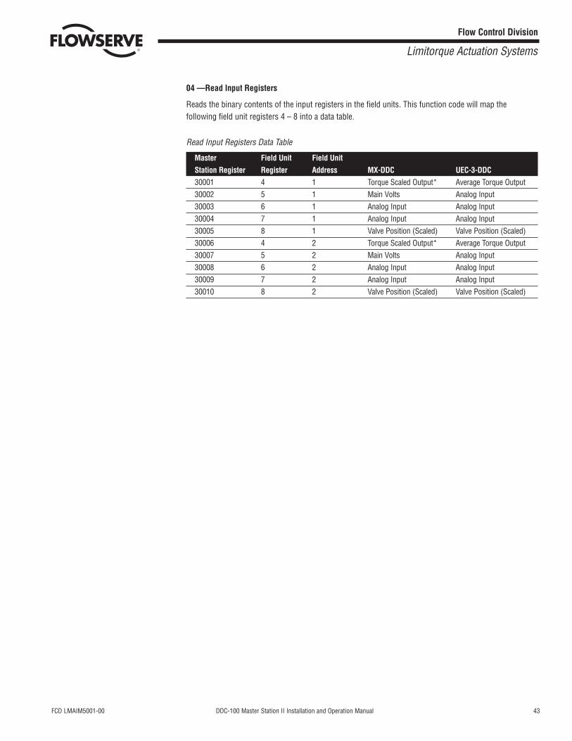
04 —Read Input Registers
Reads the binary contents of the input registers in the field units. This function code will map thefollowing field unit registers 4 – 8 into a data table.
Read Input Registers Data Table
Master Field Unit Field Unit Station Register Register Address MX-DDC UEC-3-DDC30001 4 1 Torque Scaled Output* Average Torque Output30002 5 1 Main Volts Analog Input30003 6 1 Analog Input Analog Input30004 7 1 Analog Input Analog Input30005 8 1 Valve Position (Scaled) Valve Position (Scaled)30006 4 2 Torque Scaled Output* Average Torque Output30007 5 2 Main Volts Analog Input30008 6 2 Analog Input Analog Input30009 7 2 Analog Input Analog Input30010 8 2 Valve Position (Scaled) Valve Position (Scaled)

44 DDC-100 Master Station II Installation and Operation Manual FCD LMAIM5001-00
Flow Control Division
Limitorque Actuation Systems
This page is intentionally blank.
FCD LMAIM5001-00 DDC-100 Master Station II Installation and Operation Manual 45
Flow Control Division
Limitorque Actuation Systems
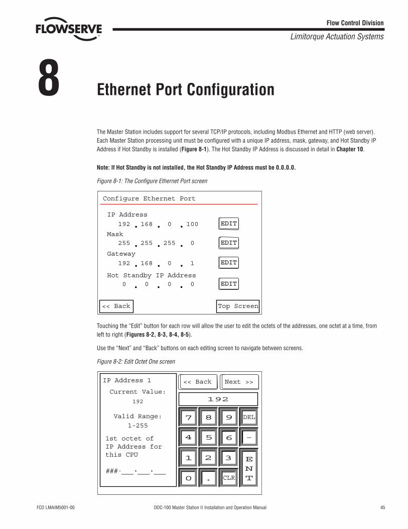
8 Ethernet Port Configuration
The Master Station includes support for several TCP/IP protocols, including Modbus Ethernet and HTTP (web server).Each Master Station processing unit must be configured with a unique IP address, mask, gateway, and Hot Standby IPAddress if Hot Standby is installed (Figure 8-1). The Hot Standby IP Address is discussed in detail in Chapter 10.
Note: If Hot Standby is not installed, the Hot Standby IP Address must be 0.0.0.0.
Figure 8-1: The Configure Ethernet Port screen
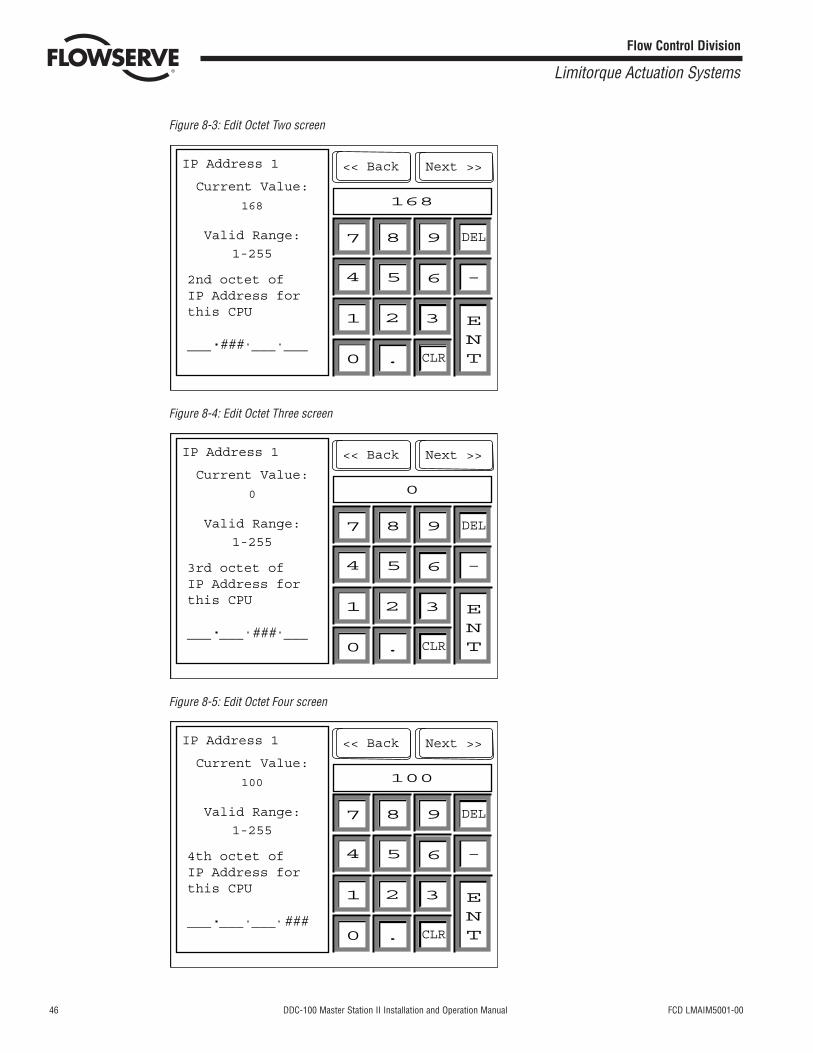
Touching the “Edit” button for each row will allow the user to edit the octets of the addresses, one octet at a time, fromleft to right (Figures 8-2, 8-3, 8-4, 8-5).
Use the “Next” and “Back” buttons on each editing screen to navigate between screens.
Figure 8-2: Edit Octet One screen
<< BackIP Address 1
Current Value:
192
1-255
Valid Range:
1st octet ofIP Address for this CPU
### ___ ___ ___
192
7 8 9
654
1 2 3
0 . CLR
DEL
-
ENT
Next >>
EDITEDIT
EDITEDIT
EDITEDIT
EDITEDIT
<< Back Top Screen
IP Address
192 168 0 100
Mask 255 255 255 0
Gateway
192 168 0 1
Hot Standby IP Address 0 0 0 0
Configure Ethernet Port
46 DDC-100 Master Station II Installation and Operation Manual FCD LMAIM5001-00
Flow Control Division
Limitorque Actuation Systems
Figure 8-3: Edit Octet Two screen
Figure 8-4: Edit Octet Three screen
Figure 8-5: Edit Octet Four screen
<< BackIP Address 1
Current Value:
100
1-255
Valid Range:
4th octet ofIP Address for this CPU
___ ___ ___ ###
100
7 8 9
654
1 2 3
0 . CLR
DEL
-
ENT
Next >>
<< BackIP Address 1
Current Value:
0
1-255
Valid Range:
3rd octet ofIP Address for this CPU
___ ___ ### ___
0
7 8 9
654
1 2 3
0 . CLR
DEL
-
ENT
Next >>
<< BackIP Address 1
Current Value:
168
1-255
Valid Range:
2nd octet ofIP Address for this CPU
___ ### ___ ___
168
7 8 9
654
1 2 3
0 . CLR
DEL
-
ENT
Next >>
FCD LMAIM5001-00 DDC-100 Master Station II Installation and Operation Manual 47
Flow Control Division
Limitorque Actuation Systems
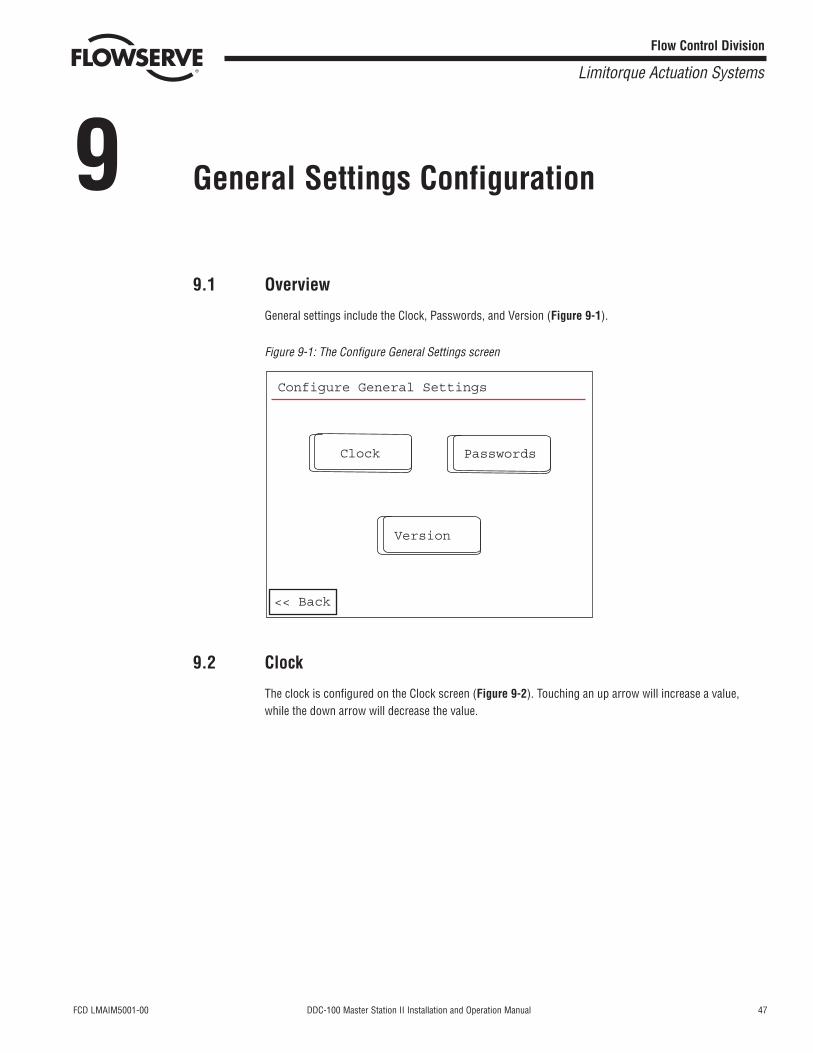
9 General Settings Configuration
9.1 Overview
General settings include the Clock, Passwords, and Version (Figure 9-1).
Figure 9-1: The Configure General Settings screen
9.2 Clock
The clock is configured on the Clock screen (Figure 9-2). Touching an up arrow will increase a value,while the down arrow will decrease the value.
Configure General Settings
Clock Passwords
Version
<< Back
48 DDC-100 Master Station II Installation and Operation Manual FCD LMAIM5001-00
Flow Control Division
Limitorque Actuation Systems
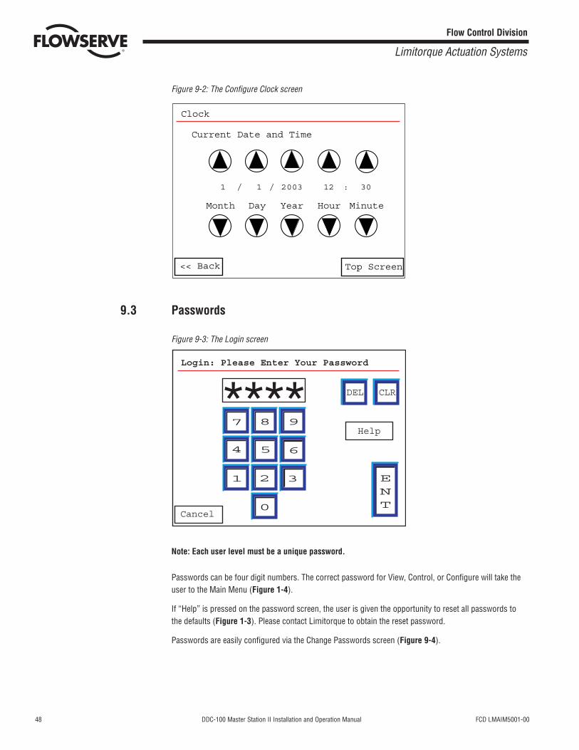
Figure 9-2: The Configure Clock screen
9.3 Passwords
Figure 9-3: The Login screen
Note: Each user level must be a unique password.
Passwords can be four digit numbers. The correct password for View, Control, or Configure will take theuser to the Main Menu (Figure 1-4).
If “Help” is pressed on the password screen, the user is given the opportunity to reset all passwords tothe defaults (Figure 1-3). Please contact Limitorque to obtain the reset password.
Passwords are easily configured via the Change Passwords screen (Figure 9-4).
7 8 9
654
1 2 3
0
DEL CLR
ENT
Cancel
Help
Login: Please Enter Your Password
****
Clock
Current Date and Time
Month Day Year Hour Minute
<< Back Top Screen
1 / 1 / 2003 12 : 30
FCD LMAIM5001-00 DDC-100 Master Station II Installation and Operation Manual 49
Flow Control Division
Limitorque Actuation Systems
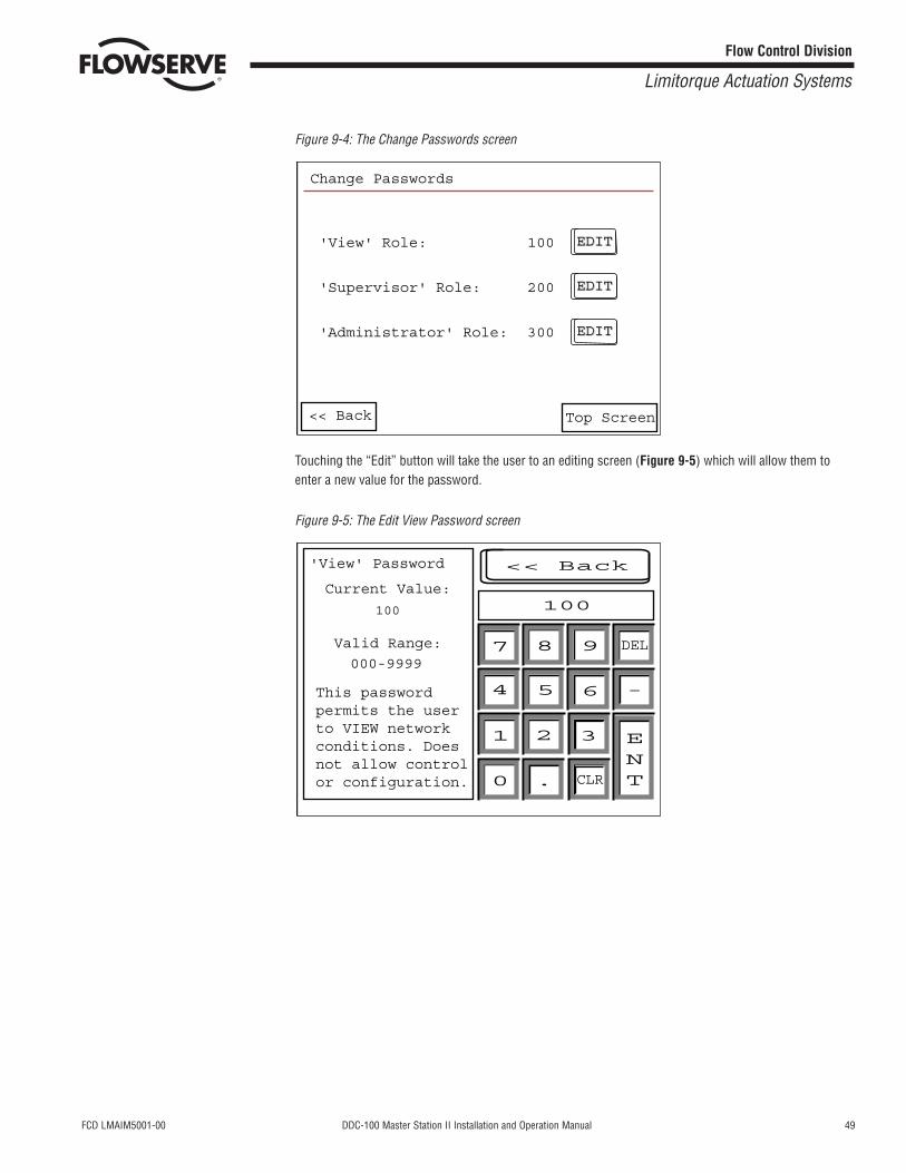
Figure 9-4: The Change Passwords screen
Touching the “Edit” button will take the user to an editing screen (Figure 9-5) which will allow them toenter a new value for the password.
Figure 9-5: The Edit View Password screen
'View' Password
Current Value:
100
000-9999
Valid Range:
This passwordpermits the userto VIEW networkconditions. Doesnot allow controlor configuration.
100
<< Back
7 8 9
654
1 2 3
0 . CLR
DEL
-
ENT
<< Back Top Screen
EDITEDIT
EDITEDIT
EDITEDIT
Change Passwords
'View' Role: 100
'Supervisor' Role: 200
'Administrator' Role: 300
50 DDC-100 Master Station II Installation and Operation Manual FCD LMAIM5001-00
Flow Control Division
Limitorque Actuation Systems
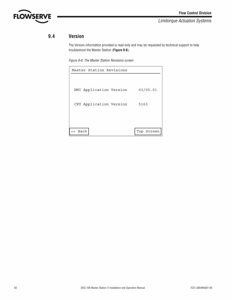
9.4 Version
The Version information provided is read-only and may be requested by technical support to helptroubleshoot the Master Station (Figure 9-6).
Figure 9-6: The Master Station Revisions screen
<< Back Top Screen
Master Station Revisions
HMI Application Version 03/05.01
CPU Application Version 5163
FCD LMAIM5001-00 DDC-100 Master Station II Installation and Operation Manual 51
Flow Control Division
Limitorque Actuation Systems
10 Hot Standby Configuration
10.1 Overview
The Master Station is capable of Hot Standby Operation. Two identical processing units communicate witheach other via an Ethernet 10-BaseT connection. One processing unit is configured to be “Hot” while theother unit is configured to be “Standby.”
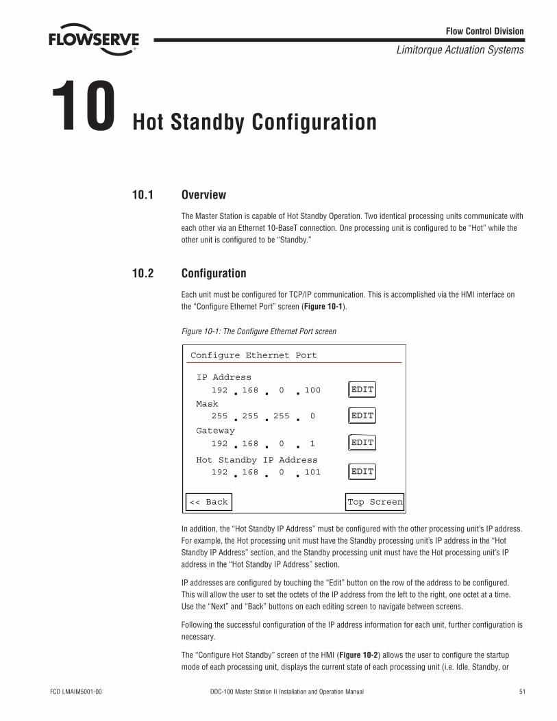
10.2 Configuration
Each unit must be configured for TCP/IP communication. This is accomplished via the HMI interface onthe “Configure Ethernet Port” screen (Figure 10-1).
Figure 10-1: The Configure Ethernet Port screen
In addition, the “Hot Standby IP Address” must be configured with the other processing unit’s IP address.For example, the Hot processing unit must have the Standby processing unit’s IP address in the “HotStandby IP Address” section, and the Standby processing unit must have the Hot processing unit’s IPaddress in the “Hot Standby IP Address” section.
IP addresses are configured by touching the “Edit” button on the row of the address to be configured.This will allow the user to set the octets of the IP address from the left to the right, one octet at a time.Use the “Next” and “Back” buttons on each editing screen to navigate between screens.
Following the successful configuration of the IP address information for each unit, further configuration isnecessary.
The “Configure Hot Standby” screen of the HMI (Figure 10-2) allows the user to configure the startupmode of each processing unit, displays the current state of each processing unit (i.e. Idle, Standby, or
EDITEDIT
EDITEDIT
EDITEDIT
EDITEDIT
<< Back Top Screen
IP Address
192 168 0 100
Mask 255 255 255 0
Gateway
192 168 0 1
Hot Standby IP Address 192 168 0 101
Configure Ethernet Port
52 DDC-100 Master Station II Installation and Operation Manual FCD LMAIM5001-00
Flow Control Division
Limitorque Actuation Systems
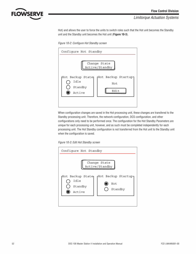
Hot) and allows the user to force the units to switch roles such that the Hot unit becomes the Standbyunit and the Standby unit becomes the Hot unit (Figure 10-3).
Figure 10-2: Configure Hot Standby screen
When configuration changes are saved in the Hot processing unit, these changes are transfered to theStandby processing unit. Therefore, the network configuration, DCS configuration, and otherconfigurations only need to be performed once. The configuration for the Hot Standby Parameters areunique for each processing unit, however, and as such must be completed independently for eachprocessing unit. The Hot Standby configuration is not transferred from the Hot unit to the Standby unitwhen the configuration is saved.
Figure 10-3: Edit Hot Standby screen
Change StateActive/Standby
Configure Hot Standby
Hot Backup State
Idle
Standby
Active
Hot Backup Startup
Hot
Standby
Change StateActive/Standby
Configure Hot Standby
Hot Backup State
Idle
Standby
Active
Hot
Edit
Hot Backup Startup
FCD LMAIM5001-00 DDC-100 Master Station II Installation and Operation Manual 53
Flow Control Division
Limitorque Actuation Systems
10.3 Operation
Under normal operating conditions, the Hot processing unit will transmit incremental data updates to theStandby processing unit via the Ethernet connection.
The Standby unit will also monitor the communication on the network to ensure that the Hot processingunit is viable.
In the event of a Hot unit failure, the Standby unit will smoothly transition into the Hot role. In addition, aforced switch may be imposed. The transition period from Hot to Standby and Standby to Hot takes under20 milliseconds to complete.
Each processing unit is capable of three states: Idle, Standby, and Hot.
Idle state: the processing unit is active, will accept incremental updates from a Hot unit, but will not performthe Hot unit’s duties nor will the processing unit switch to Hot state should a Hot failure be detected.
Standby state: the processing unit is active, will accept incremental updates from a Hot unit, and willswitch to Hot state should a Hot failure be detected.
Hot state: the processing unit is the Hot unit and will perform the Hot duties of Network polling andincremental updating of the Standby processing unit.
A state change can occur in any of the following conditions:
Hot Unit Failure: the Hot unit fails to send incremental updates to the Standby unit and there is nonetwork traffic.
Hot-Standby communication failure: the Standby unit is not receiving incremental update informationfrom the Hot unit but detects Network traffic. The Standby unit will zero its database and set an alert error.The HMI will detect this state and will display “Idle” instead of “Standby”.

54 DDC-100 Master Station II Installation and Operation Manual FCD LMAIM5001-00
Flow Control Division
Limitorque Actuation Systems
This page is intentionally blank.
FCD LMAIM5001-00 DDC-100 Master Station II Installation and Operation Manual 55
Flow Control Division
Limitorque Actuation Systems
11 Network Status
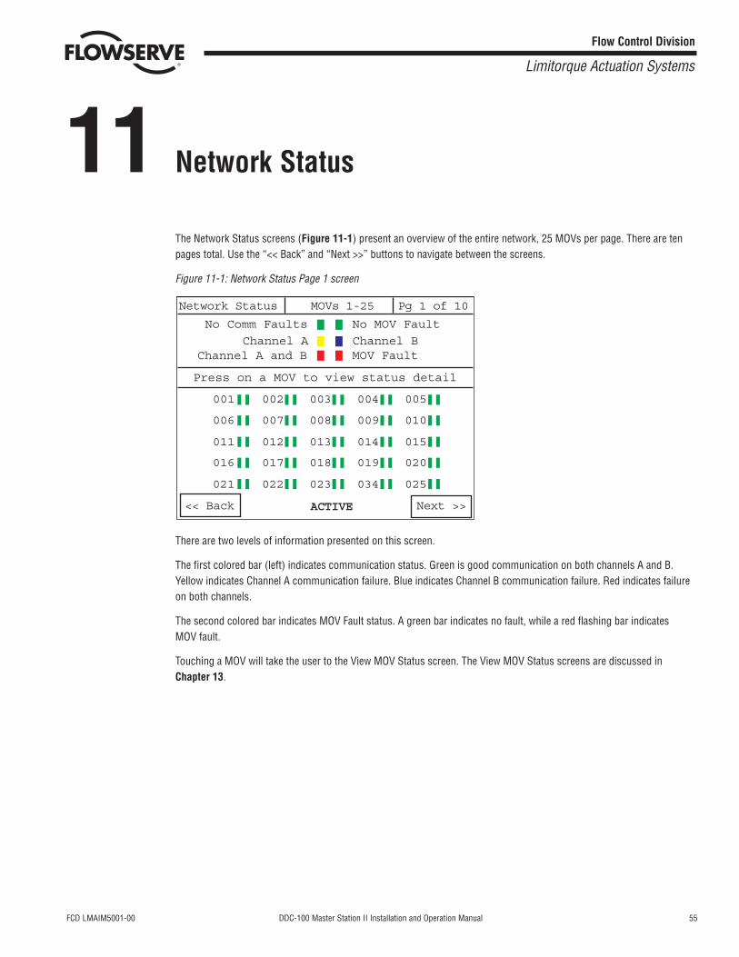
The Network Status screens (Figure 11-1) present an overview of the entire network, 25 MOVs per page. There are tenpages total. Use the “<< Back” and “Next >>” buttons to navigate between the screens.
Figure 11-1: Network Status Page 1 screen
There are two levels of information presented on this screen.
The first colored bar (left) indicates communication status. Green is good communication on both channels A and B.Yellow indicates Channel A communication failure. Blue indicates Channel B communication failure. Red indicates failureon both channels.
The second colored bar indicates MOV Fault status. A green bar indicates no fault, while a red flashing bar indicates MOV fault.
Touching a MOV will take the user to the View MOV Status screen. The View MOV Status screens are discussed inChapter 13.
Network Status MOVs 1-25 Pg 1 of 10
<< Back Next >>ACTIVE
No Comm Faults
Channel A Channel BMOV Fault
Press on a MOV to view status detail
001 002 003 004 005
006 007 008 009 010
011 012 013 014 015
016 017 018 019 020
021 022 023 034 025
Channel A and B
No MOV Fault

56 DDC-100 Master Station II Installation and Operation Manual FCD LMAIM5001-00
Flow Control Division
Limitorque Actuation Systems
This page is intentionally blank.
FCD LMAIM5001-00 DDC-100 Master Station II Installation and Operation Manual 57
Flow Control Division
Limitorque Actuation Systems
12 View MOV Status
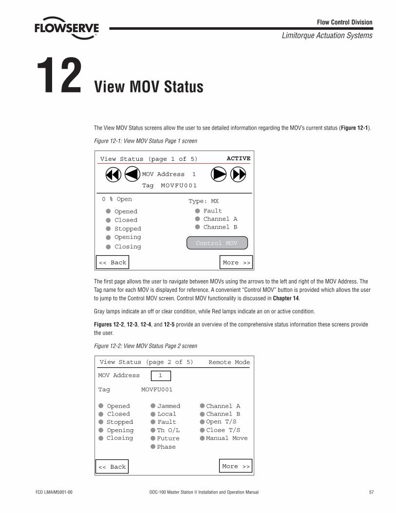
The View MOV Status screens allow the user to see detailed information regarding the MOV’s current status (Figure 12-1).
Figure 12-1: View MOV Status Page 1 screen
The first page allows the user to navigate between MOVs using the arrows to the left and right of the MOV Address. TheTag name for each MOV is displayed for reference. A convenient “Control MOV” button is provided which allows the userto jump to the Control MOV screen. Control MOV functionality is discussed in Chapter 14.
Gray lamps indicate an off or clear condition, while Red lamps indicate an on or active condition.
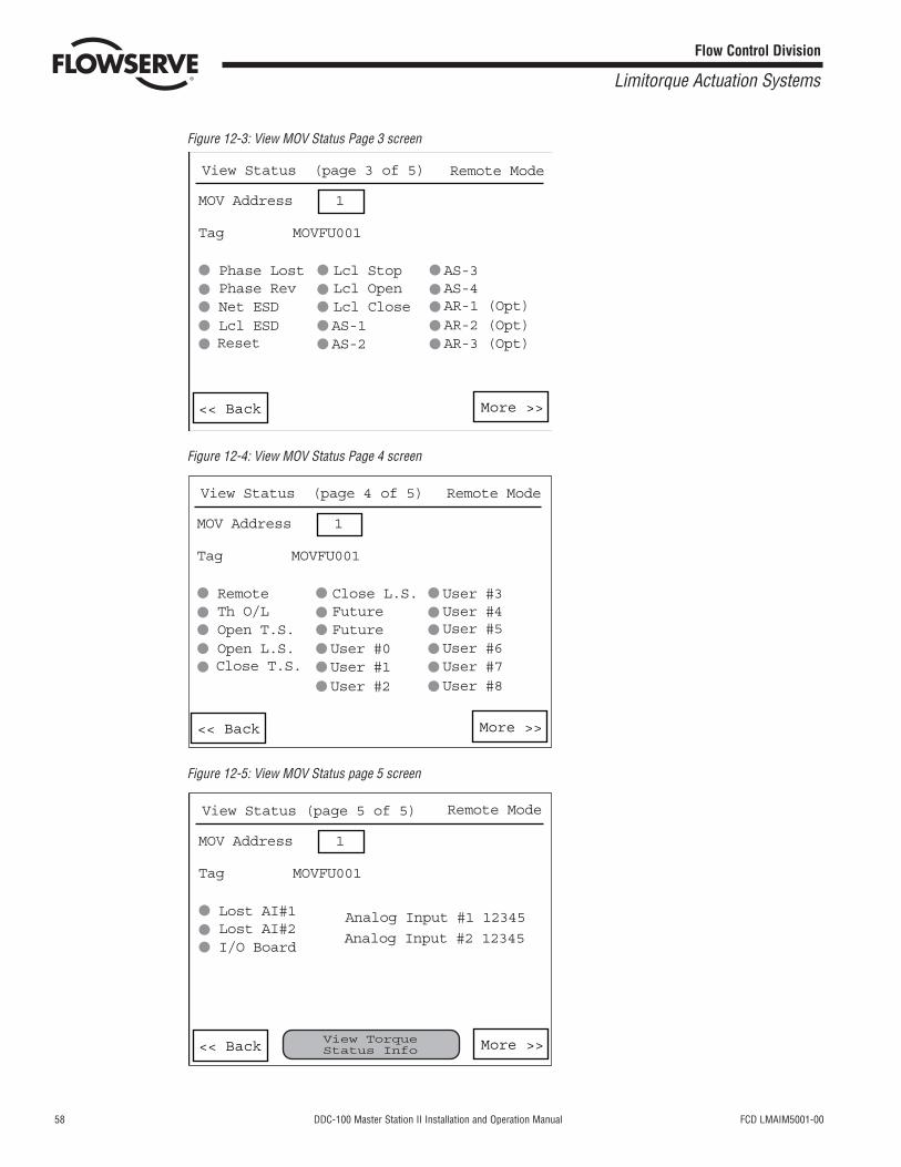
Figures 12-2, 12-3, 12-4, and 12-5 provide an overview of the comprehensive status information these screens providethe user.
Figure 12-2: View MOV Status Page 2 screen
<< Back More >>
MOV Address 1
View Status (page 2 of 5)
Tag MOVFU001
Opened JammedLocalFault
FutureTh O/L
Phase
Channel AChannel BOpen T/SClose T/SManual Move
ClosedStopped
Remote Mode
OpeningClosing
View Status (page 1 of 5)
MOV Address 1
Tag MOVFU001
ACTIVE
<< Back More >>
0 % Open
OpenedClosed
StoppedOpening
Closing
FaultChannel AChannel B
Control MOV
Type: MX
58 DDC-100 Master Station II Installation and Operation Manual FCD LMAIM5001-00
Flow Control Division
Limitorque Actuation Systems
Figure 12-3: View MOV Status Page 3 screen
Figure 12-4: View MOV Status Page 4 screen
Figure 12-5: View MOV Status page 5 screen
<< Back More >>
MOV Address 1
View Status (page 5 of 5)
Tag MOVFU001
Lost AI#1
Remote Mode
Lost AI#2I/O Board
Analog Input #1 12345
Analog Input #2 12345
View Torque Status Info
<< Back More >>
MOV Address 1
View Status (page 4 of 5)
Tag MOVFU001
Remote
Remote Mode
Close L.S.FutureFuture
User #1User #0
User #3User #4User #5User #6User #7
Th O/LOpen T.S.Open L.S.Close T.S.
User #2 User #8
<< Back More >>
MOV Address 1
View Status (page 3 of 5)
Tag MOVFU001
Phase Lost
Remote Mode
Lcl StopLcl OpenLcl Close
AS-2AS-1
AS-3AS-4AR-1 (Opt)AR-2 (Opt)AR-3 (Opt)
Phase RevNet ESDLcl ESDReset
FCD LMAIM5001-00 DDC-100 Master Station II Installation and Operation Manual 59
Flow Control Division
Limitorque Actuation Systems
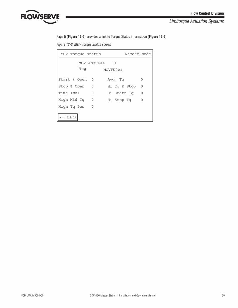
Page 5 (Figure 12-5) provides a link to Torque Status information (Figure 12-6).
Figure 12-6: MOV Torque Status screen
Start % Open 0
Stop % Open 0
Time (ms) 0
High Mid Tq 0
High Tq Pos 0
Avg. Tq 0
Remote Mode
Hi Tq @ Stop 0
Hi Start Tq 0
Hi Stop Tq 0
<< Back
MOV Address 1
MOV Torque Status
Tag MOVFU001

60 DDC-100 Master Station II Installation and Operation Manual FCD LMAIM5001-00
Flow Control Division
Limitorque Actuation Systems
This page is intentionally blank.
FCD LMAIM5001-00 DDC-100 Master Station II Installation and Operation Manual 61
Flow Control Division
Limitorque Actuation Systems
13 Control MOV
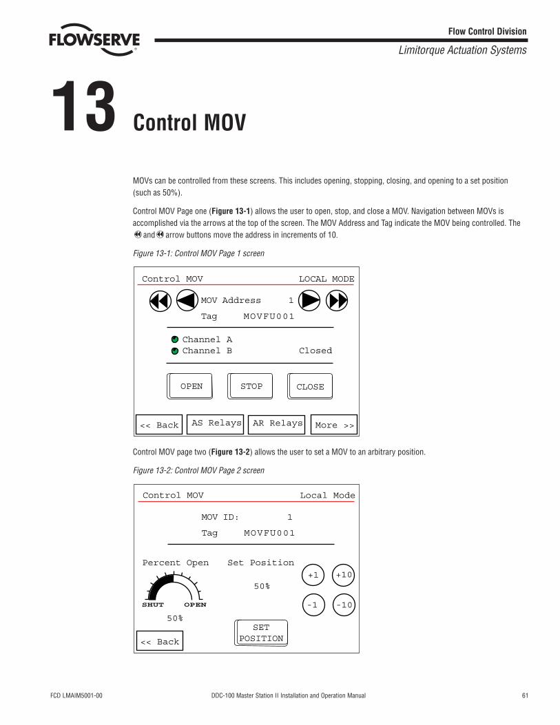
MOVs can be controlled from these screens. This includes opening, stopping, closing, and opening to a set position(such as 50%).
Control MOV Page one (Figure 13-1) allows the user to open, stop, and close a MOV. Navigation between MOVs isaccomplished via the arrows at the top of the screen. The MOV Address and Tag indicate the MOV being controlled. The
and arrow buttons move the address in increments of 10.
Figure 13-1: Control MOV Page 1 screen
Control MOV page two (Figure 13-2) allows the user to set a MOV to an arbitrary position.
Figure 13-2: Control MOV Page 2 screen
Control MOV
MOV ID: 1
Tag MOVFU001
SETPOSITION
Percent Open Set Position
50%
Local Mode
50%
SHUT OPEN
+1 +10
-1 -10
<< Back
Control MOV
MOV Address 1
Tag MOVFU001
Channel AChannel B Closed
OPEN
LOCAL MODE
STOP CLOSE
<< Back More >>AR RelaysAS Relays
62 DDC-100 Master Station II Installation and Operation Manual FCD LMAIM5001-00
Flow Control Division
Limitorque Actuation Systems
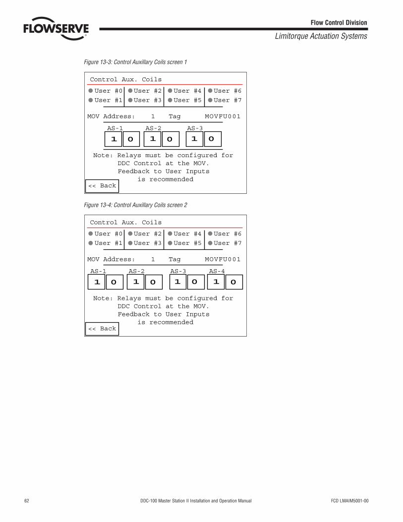
Figure 13-3: Control Auxillary Coils screen 1
Figure 13-4: Control Auxillary Coils screen 2
Control Aux. Coils
<< Back
MOV Address: 1 Tag MOVFU001
Note: Relays must be configured for DDC Control at the MOV. Feedback to User Inputs is recommended
AS-1 AS-2 AS-3 AS-4
User #0 User #2 User #4 User #6
User #1 User #3 User #5 User #7
1 1 1 1 0000
Control Aux. Coils
<< Back
MOV Address: 1 Tag MOVFU001
Note: Relays must be configured for DDC Control at the MOV. Feedback to User Inputs is recommended
AS-1 AS-2 AS-3
User #0 User #2 User #4 User #6
User #1 User #3 User #5 User #7
1 1 1 000
FCD LMAIM5001-00 DDC-100 Master Station II Installation and Operation Manual 63
Flow Control Division
Limitorque Actuation Systems
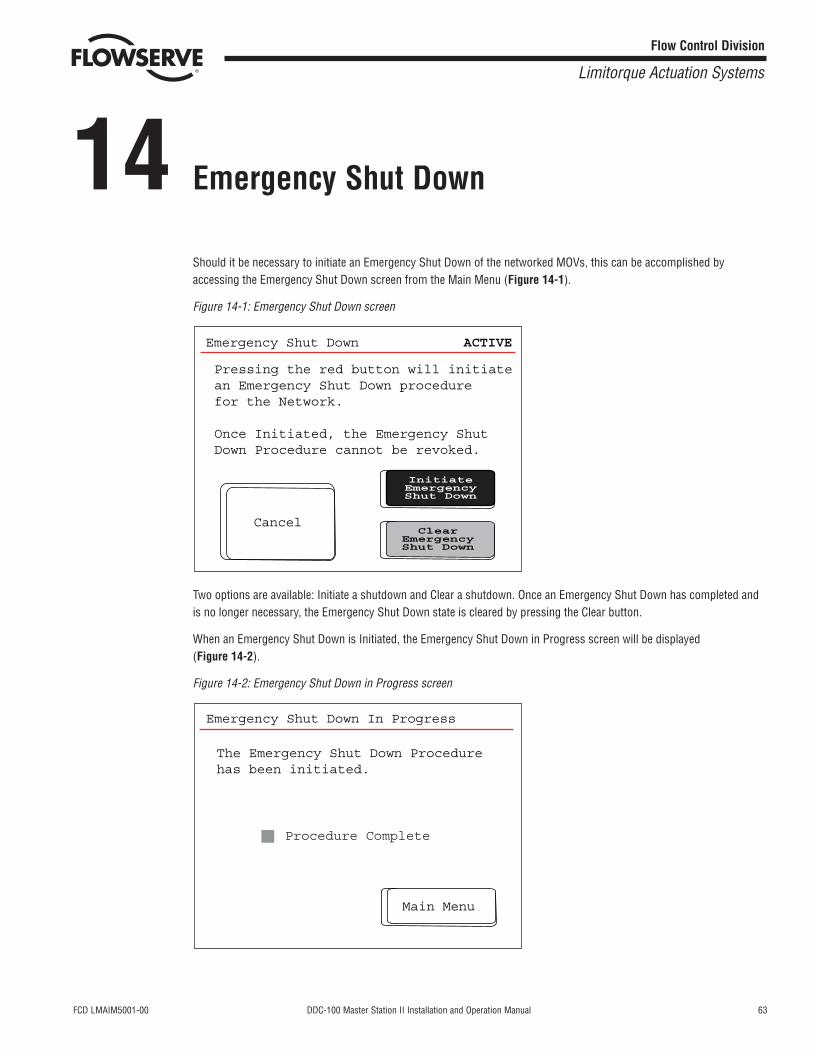
14 Emergency Shut Down
Should it be necessary to initiate an Emergency Shut Down of the networked MOVs, this can be accomplished byaccessing the Emergency Shut Down screen from the Main Menu (Figure 14-1).
Figure 14-1: Emergency Shut Down screen
Two options are available: Initiate a shutdown and Clear a shutdown. Once an Emergency Shut Down has completed andis no longer necessary, the Emergency Shut Down state is cleared by pressing the Clear button.
When an Emergency Shut Down is Initiated, the Emergency Shut Down in Progress screen will be displayed (Figure 14-2).
Figure 14-2: Emergency Shut Down in Progress screen
Emergency Shut Down In Progress
The Emergency Shut Down Procedurehas been initiated.
Main Menu
Procedure Complete
Emergency Shut Down ACTIVE
Pressing the red button will initiatean Emergency Shut Down procedurefor the Network.
Once Initiated, the Emergency ShutDown Procedure cannot be revoked.
ClearEmergencyShut Down
InitiateEmergencyShut Down
Cancel
64 DDC-100 Master Station II Installation and Operation Manual FCD LMAIM5001-00
Flow Control Division
Limitorque Actuation Systems
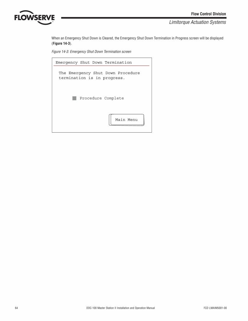
When an Emergency Shut Down is Cleared, the Emergency Shut Down Termination in Progress screen will be displayed(Figure 14-3).
Figure 14-3: Emergency Shut Down Termination screen
Emergency Shut Down Termination
The Emergency Shut Down Proceduretermination is in progress.
Main Menu
Procedure Complete
FCD LMAIM5001-00 DDC-100 Master Station II Installation and Operation Manual 65
Flow Control Division
Limitorque Actuation Systems
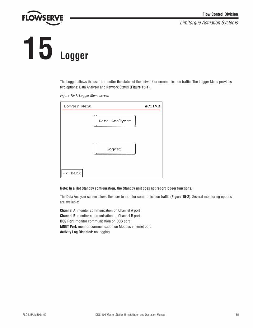
15 Logger
The Logger allows the user to monitor the status of the network or communication traffic. The Logger Menu providestwo options: Data Analyzer and Network Status (Figure 15-1).
Figure 15-1: Logger Menu screen
Note: In a Hot Standby configuration, the Standby unit does not report logger functions.
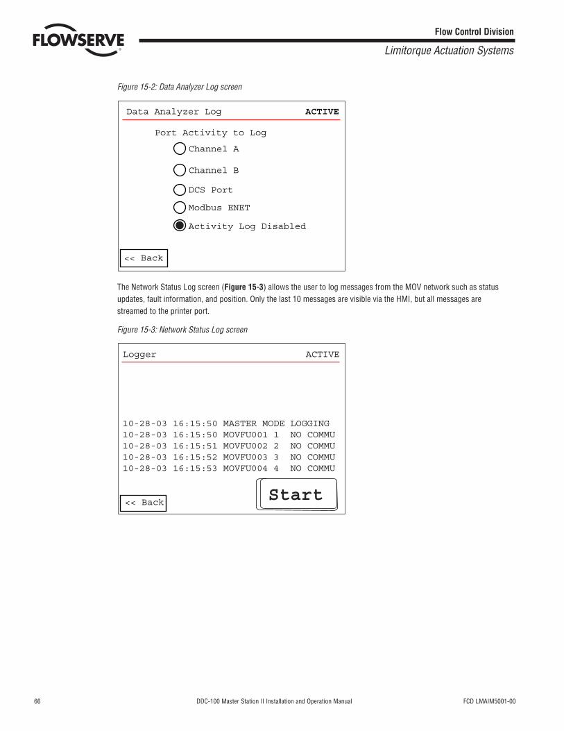
The Data Analyzer screen allows the user to monitor communication traffic (Figure 15-2). Several monitoring options are available:
Channel A: monitor communication on Channel A portChannel B: monitor communication on Channel B portDCS Port: monitor communication on DCS portMNET Port: monitor communication on Modbus ethernet portActivity Log Disabled: no logging
Logger
Data Analyzer
Logger Menu ACTIVE
<< Back
66 DDC-100 Master Station II Installation and Operation Manual FCD LMAIM5001-00
Flow Control Division
Limitorque Actuation Systems
Figure 15-2: Data Analyzer Log screen
The Network Status Log screen (Figure 15-3) allows the user to log messages from the MOV network such as statusupdates, fault information, and position. Only the last 10 messages are visible via the HMI, but all messages arestreamed to the printer port.
Figure 15-3: Network Status Log screen
Logger ACTIVE
10-28-03 16:15:50 MASTER MODE LOGGING10-28-03 16:15:50 MOVFU001 1 NO COMMU10-28-03 16:15:51 MOVFU002 2 NO COMMU10-28-03 16:15:52 MOVFU003 3 NO COMMU10-28-03 16:15:53 MOVFU004 4 NO COMMU
Start<< Back
Data Analyzer Log ACTIVE
Channel A
Channel B
DCS Port
Modbus ENET
Activity Log Disabled
<< Back
Port Activity to Log
FCD LMAIM5001-00 DDC-100 Master Station II Installation and Operation Manual 67
Flow Control Division
Limitorque Actuation Systems
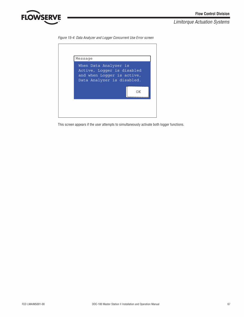
Figure 15-4: Data Analyzer and Logger Concurrent Use Error screen
This screen appears if the user attempts to simultaneously activate both logger functions.
OK
When Data Analyzer isActive, Logger is disabledand when Logger is active,Data Analyzer is disabled.
Message

68 DDC-100 Master Station II Installation and Operation Manual FCD LMAIM5001-00
Flow Control Division
Limitorque Actuation Systems
This page is intentionally blank.
FCD LMAIM5001-00 DDC-100 Master Station II Installation and Operation Manual 69
Flow Control Division
Limitorque Actuation Systems
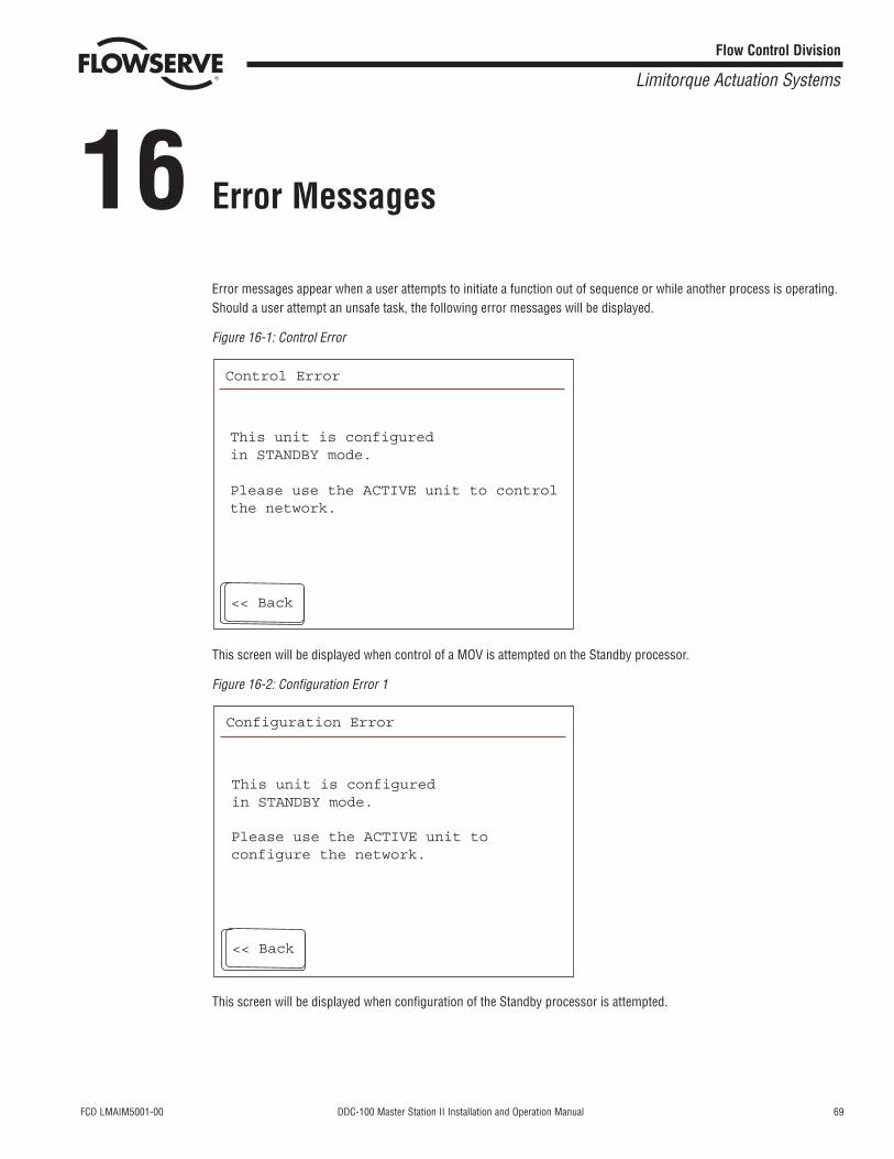
16 Error Messages
Error messages appear when a user attempts to initiate a function out of sequence or while another process is operating.Should a user attempt an unsafe task, the following error messages will be displayed.
Figure 16-1: Control Error
This screen will be displayed when control of a MOV is attempted on the Standby processor.
Figure 16-2: Configuration Error 1
This screen will be displayed when configuration of the Standby processor is attempted.
Configuration Error
Please use the ACTIVE unit toconfigure the network.
This unit is configuredin STANDBY mode.
<< Back
Control Error
This unit is configuredin STANDBY mode.
Please use the ACTIVE unit to controlthe network.
<< Back
70 DDC-100 Master Station II Installation and Operation Manual FCD LMAIM5001-00
Flow Control Division
Limitorque Actuation Systems
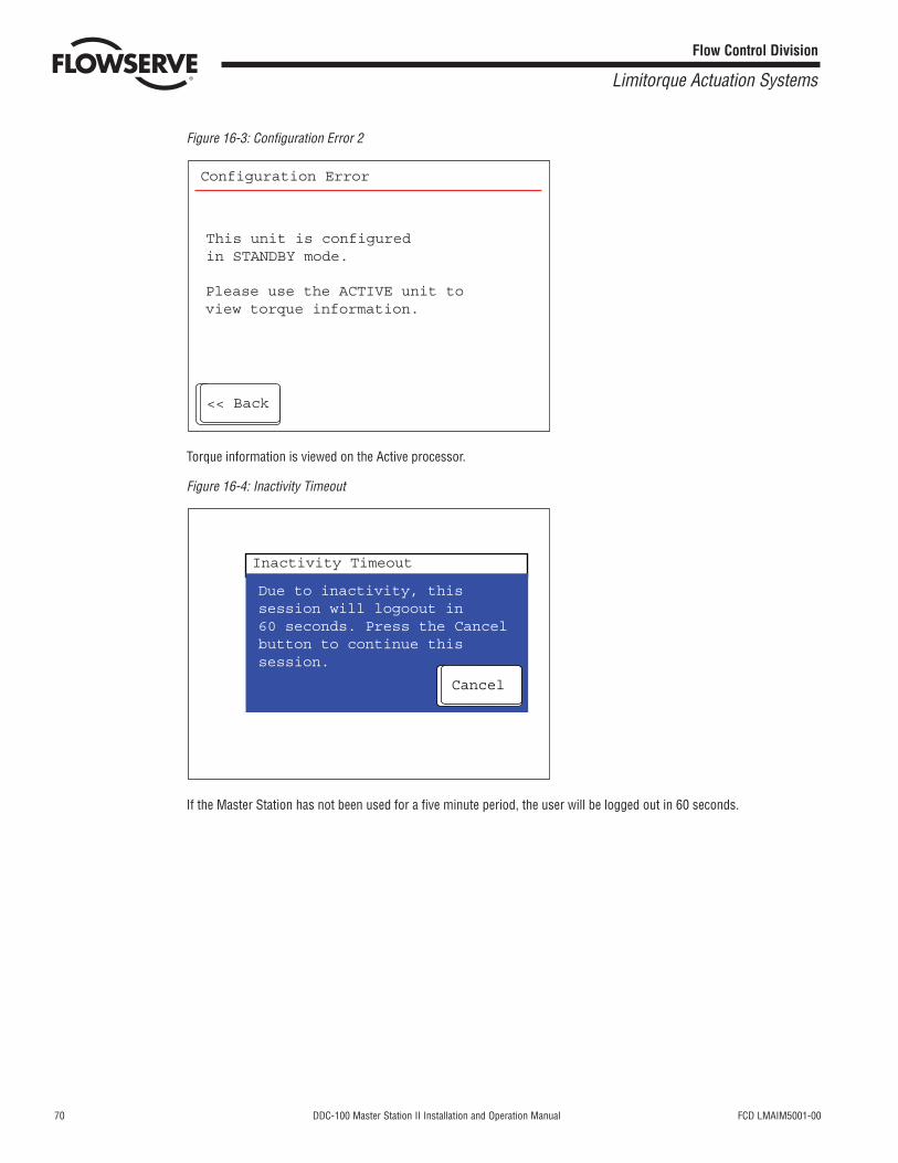
Figure 16-3: Configuration Error 2
Torque information is viewed on the Active processor.
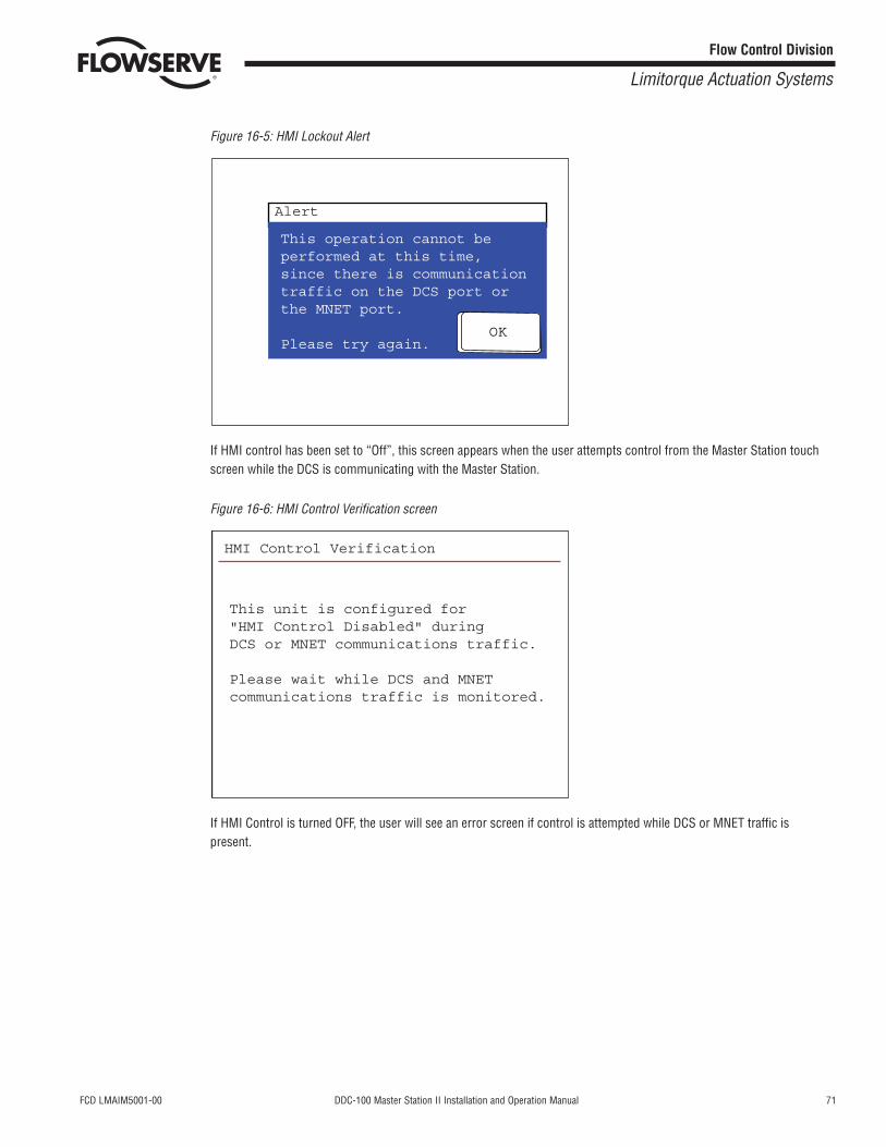
Figure 16-4: Inactivity Timeout
If the Master Station has not been used for a five minute period, the user will be logged out in 60 seconds.
Cancel
Due to inactivity, thissession will logoout in60 seconds. Press the Cancelbutton to continue thissession.
Inactivity Timeout
Configuration Error
Please use the ACTIVE unit toview torque information.
This unit is configuredin STANDBY mode.
<< Back
FCD LMAIM5001-00 DDC-100 Master Station II Installation and Operation Manual 71
Flow Control Division
Limitorque Actuation Systems
Figure 16-5: HMI Lockout Alert
If HMI control has been set to “Off”, this screen appears when the user attempts control from the Master Station touchscreen while the DCS is communicating with the Master Station.
Figure 16-6: HMI Control Verification screen
If HMI Control is turned OFF, the user will see an error screen if control is attempted while DCS or MNET traffic ispresent.
HMI Control Verification
This unit is configured for"HMI Control Disabled" duringDCS or MNET communications traffic.
Please wait while DCS and MNET communications traffic is monitored.
OK
This operation cannot beperformed at this time,since there is communicationtraffic on the DCS port orthe MNET port.
Please try again.
Alert

72 DDC-100 Master Station II Installation and Operation Manual FCD LMAIM5001-00
Flow Control Division
Limitorque Actuation Systems
This page is intentionally blank.
FCD LMAIM5001-00 DDC-100 Master Station II Installation and Operation Manual 73
Flow Control Division
Limitorque Actuation Systems
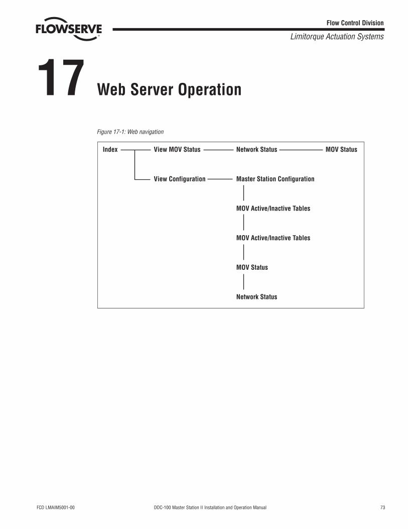
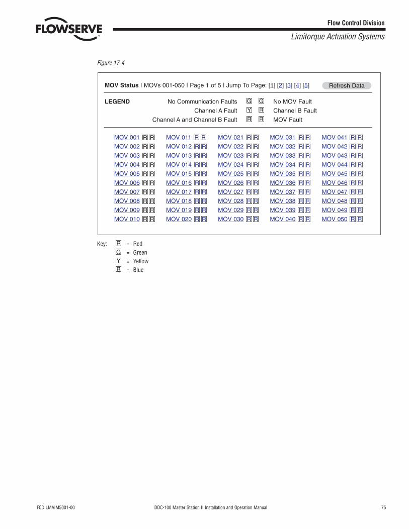
17 Web Server Operation
Figure 17-1: Web navigation
Index View MOV Status Network Status
View Configuration Master Station Configuration
MOV Active/Inactive Tables
MOV Active/Inactive Tables
MOV Status
Network Status
MOV Status
74 DDC-100 Master Station II Installation and Operation Manual FCD LMAIM5001-00
Flow Control Division
Limitorque Actuation Systems
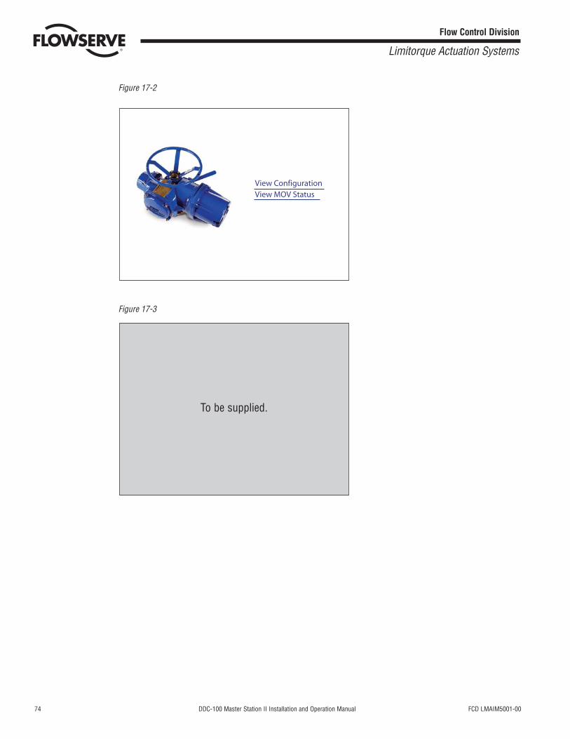
Figure 17-2
Figure 17-3
To be supplied.
View ConfigurationView MOV Status
FCD LMAIM5001-00 DDC-100 Master Station II Installation and Operation Manual 75
Flow Control Division
Limitorque Actuation Systems
Figure 17-4
Key: = Red= Green= Yellow= BlueB
YGR
MOV Status | MOVs 001-050 | Page 1 of 5 | Jump To Page: [1] [2] [3] [4] [5]
LEGEND No Communication Faults No MOV Fault
Channel A Fault Channel B Fault
Channel A and Channel B Fault MOV FaultRR
RY
GG
Refresh Data
MOV 001
MOV 002
MOV 003
MOV 004
MOV 005
MOV 006
MOV 007
MOV 008
MOV 009
MOV 010
MOV 011
MOV 012
MOV 013
MOV 014
MOV 015
MOV 016
MOV 017
MOV 018
MOV 019
MOV 020
MOV 021
MOV 022
MOV 023
MOV 024
MOV 025
MOV 026
MOV 027
MOV 028
MOV 029
MOV 030
MOV 031
MOV 032
MOV 033
MOV 034
MOV 035
MOV 036
MOV 037
MOV 038
MOV 039
MOV 040
MOV 041
MOV 042
MOV 043
MOV 044
MOV 045
MOV 046
MOV 047
MOV 048
MOV 049
MOV 050 RR
RR
RR
RR
RR
RR
RR
RR
RR
RR
RR
RR
RR
RR
RR
RR
RR
RR
RR
RR
RR
RR
RR
RR
RR
RR
RR
RR
RR
RR
RR
RR
RR
RR
RR
RR
RR
RR
RR
RR
RR
RR
RR
RR
RR
RR
RR
RR
RR
RR
76 DDC-100 Master Station II Installation and Operation Manual FCD LMAIM5001-00
Flow Control Division
Limitorque Actuation Systems
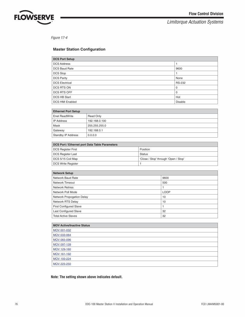
Figure 17-4
Note: The setting shown above indicates default.
Master Station Confi guration
DCS Port Setup
DCS Address 1
DCS Baud Rate 9600
DCS Stop 1
DCS Parity None
DCS Electrical RS-232
DCS RTS ON 0
DCS RTS OFF 0
DCS HB Start Hot
DCS HMI Enabled Disable
Ethernet Port Setup
Enet ReadWrite Read Only
IP Address 192.168.0.100
Mask 255.255.255.0
Gateway 192.168.0.1
Standby IP Address 0.0.0.0
DCS Port / Ethernet port Data Table Parameters
DCS Register First Position
DCS Register Last Status
DCS 5/15 Coil Map ‘Close / Stop’ through ‘Open / Stop’
DCS Write Register 1
Network Setup
Network Baud Rate 9600
Network Timeout 500
Network Retries 1
Network Poll Mode LOOP
Network Propogation Delay 10
Network RTS Delay 10
First Confi gured Slave 1
Last Confi gured Slave 32
Total Active Slaves 32
MOV Active/Inactive Status
MOV 001-032
MOV 033-064
MOV 065-096
MOV 097-128
MOV 129-160
MOV 161-192
MOV 193-224
MOV 225-250
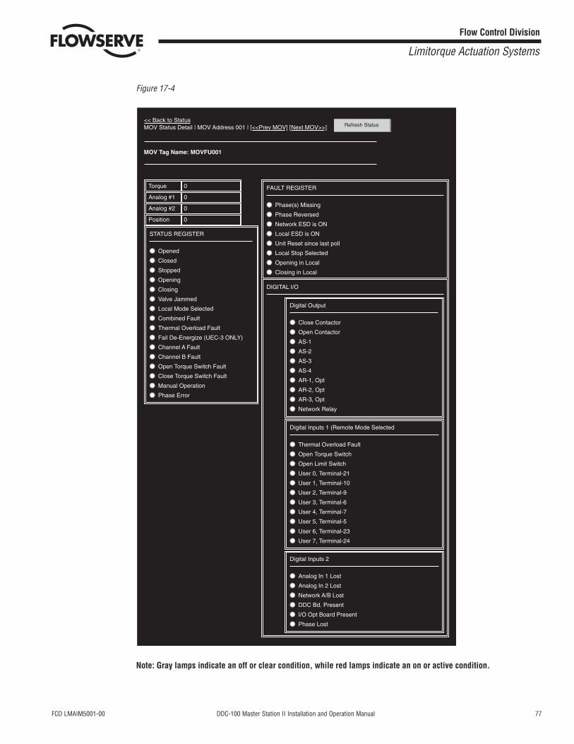
FCD LMAIM5001-00 DDC-100 Master Station II Installation and Operation Manual 77
Flow Control Division
Limitorque Actuation Systems
Figure 17-4
Note: Gray lamps indicate an off or clear condition, while red lamps indicate an on or active condition.
<< Back to StatusMOV Status Detail | MOV Address 001 | [<<Prev MOV] [Next MOV>>]
MOV Tag Name: MOVFU001
Torque 0
Analog #1 0
Analog #2 0
Position 0
STATUS REGISTER
Opened
Closed
Stopped
Opening
Closing
Valve Jammed
Local Mode Selected
Combined Fault
Thermal Overload Fault
Fail De-Energize (UEC-3 ONLY)
Channel A Fault
Channel B Fault
Open Torque Switch Fault
Digital Output
Close Contactor
Open Contactor
AS-1
AS-2
AS-3
AS-4
AR-1, Opt
AR-2, Opt
AR-3, Opt
Digital Inputs 1 (Remote Mode Selected
Thermal Overload Fault
Open Torque Switch
Open Limit Switch
User 0, Terminal-21
User 1, Terminal-10
User 2, Terminal-9
User 3, Terminal-6
User 4, Terminal-7
User 5, Terminal-5
User 6, Terminal-23
User 7, Terminal-24
Digital Inputs 2
Analog In 1 Lost
Analog In 2 Lost
Network A/B Lost
DDC Bd. Present
I/O Opt Board Present
Phase Lost
Network Relay
Close Torque Switch Fault
Manual Operation
Phase Error
FAULT REGISTER
DIGITAL I/O
Phase(s) Missing
Phase Reversed
Network ESD is ON
Local ESD is ON
Unit Reset since last poll
Local Stop Selected
Opening in Local
Closing in Local
Refresh Status

78 DDC-100 Master Station II Installation and Operation Manual FCD LMAIM5001-00
Flow Control Division
Limitorque Actuation Systems
This page is intentionally blank.

FCD LMAIM5001-00 DDC-100 Master Station II Installation and Operation Manual 79
Flow Control Division
Limitorque Actuation Systems
18 Touch Panel Backlight
When the touch panel backlight burns out, the panel’s status LED will turn orange. The HMI is programmed for touchoperation to be disabled when the backlight burns out, which prevents the panel from sending commands to the PLC.
The touch panel unit uses a CCFL, long-life type backlight. The actual life of the backlight however, will vary depending onthe operating conditions, and replacement may be required. The backlight has a life of 30,000 hours (approximately 3.4years), when the backlight is lit continuously (time required for brightness to fall to half its normal level).
Note: The touch panel screen saver feature is enabled to prevent continuous backlight operation for a longerbacklight life expectancy.
Pro-face part number: GP377L/S-BL00-MS
Warning• To prevent an electric shock, be sure the touch panel’s power is disconnected from the power supply prior to
changing the backlight.
• When the power has just been turned OFF, the unit and backlight are still very hot. Be sure to use gloves to preventburns.
• The backlight is very fragile. Do not touch the glass tube directly or try to remove its power cord. If the glass tubebreaks, you may be injured.
Use the following steps to change the backlight. Be sure to use gloves.
1. Turn OFF power to the Master Station. Disconnect power.2. Remove the power and serial cables from the touch panel and remove from the Master Station.
3. Unscrew the panel’s two (2) top face attachment screws.4. Push down on the lock clip and open the panel’s rear cover.5. Disconnect the backlight's power connector from the inverter board. Do not try to pull the cord out of the backlight.6. Push the backlight's lock tab to the right to free the backlight, then pull it upwards and out of the unit.
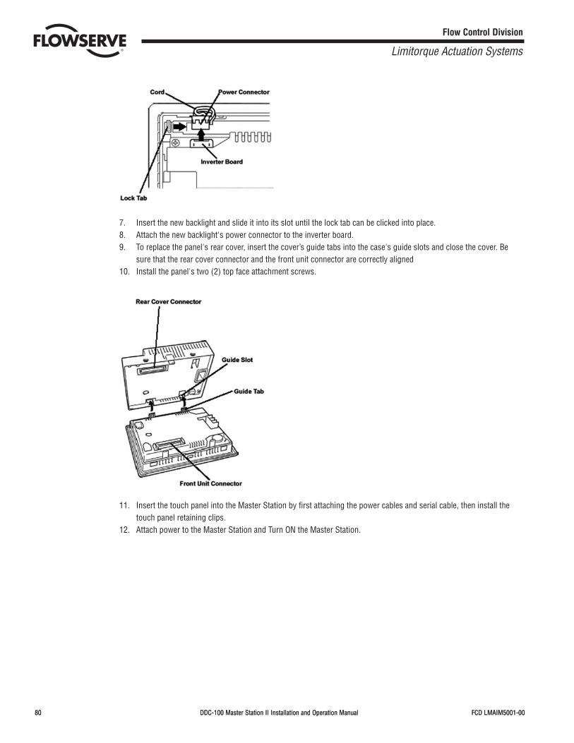
80 DDC-100 Master Station II Installation and Operation Manual FCD LMAIM5001-00
Flow Control Division
Limitorque Actuation Systems
80 DDC-100 Master Station II Installation and Operation Manual FCD LMAIM5001-00
7. Insert the new backlight and slide it into its slot until the lock tab can be clicked into place.8. Attach the new backlight's power connector to the inverter board.9. To replace the panel's rear cover, insert the cover’s guide tabs into the case's guide slots and close the cover. Be
sure that the rear cover connector and the front unit connector are correctly aligned10. Install the panel's two (2) top face attachment screws.
11. Insert the touch panel into the Master Station by first attaching the power cables and serial cable, then install thetouch panel retaining clips.
12. Attach power to the Master Station and Turn ON the Master Station.

FCD LMAIM5001-00 DDC-100 Master Station II Installation and Operation Manual 81
Flow Control Division
Limitorque Actuation Systems
FCD LMAIM5001-00 DDC-100 Master Station II Installation and Operation Manual 81
19 FTP Upload of MOV Tag Name Database
Using an FTP software application, connect to the Master Station TCP/IP port. Log onto the Master Station.

82 DDC-100 Master Station II Installation and Operation Manual FCD LMAIM5001-00
This page is intentionally blank.
Flow Control Division
Limitorque Actuation Systems
FCD LMAIM5001-00 DDC-100 Master Station II Installation and Operation Manual 83
20 How to Order Parts
To order parts or obtain further information about your Flowserve Limitorque Master Station II, contact your localLimitorque distributor sales office, or:
FLOWSERVE CORPORATIONLimitorque Actuation Systems5114 Woodall RoadP.O.Box 11318Lynchburg, VA 24506-1318Phone (434) 528-4400Fax (434) 845-9736
To find the Limitorque distributor or sales office near you, go to http://www.limitorque.com
All inquiries or orders must be accompanied by the following information supplied on the actuator nameplate:1. Master Station model2. Order number3. Serial number
Flow Control Division
Limitorque Actuation Systems

84 DDC-100 Master Station II Installation and Operation Manual FCD LMAIM5001-00
This page is intentionally blank.
Flow Control Division
Limitorque Actuation Systems

FCD LMAIM5001-00 DDC-100 Master Station II Installation and Operation Manual 85
21 Appendix
Figure A-1: Typical single Master Station II network diagram
Flow Control Division
Limitorque Actuation Systems
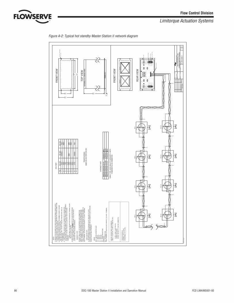
86 DDC-100 Master Station II Installation and Operation Manual FCD LMAIM5001-00
Figure A-2: Typical hot standby Master Station II network diagram
Lim
itorq
ue A
ctua
tion
Syst
ems
R
REV
ISIO
N
RACK
MOU
NTAB
LE H
OTST
AND
BY M
ASTE
R S
TATI
ON
TITL
E
DR
AWIN
G N
O.
1ST
OR
DER
NO
.AP
PRO
VED
CHEC
KED
DR
AWN
DAT
ED
ESC
RIP
TIO
NN
O.
REV
SHEE
T
OF
DAT
E
DAT
E
DAT
E
15-4
93-0
384-
41
1
DKA
9/1
2/03
L-78
3 RE
V-A
4/26
/93
MOV
-3
SEE
NOTE
5
A1*
15
A1
16
29
A2*
41
A2
MOV
-2
SEE
NOTE
5
A1*
15
A1
16
29
A2*
41
A2
MOV
-1
SEE
NOTE
5
A1*
15
A1
16
29
A2*
41
A2
MOV
-248
SEE
NOTE
5
A1*
15
A1
16
29
A2*
41
A2
MOV
-249
SEE
NOTE
5
A1*
15
A1
16
29
A2*
41
A2
MOV
-250
SEE
NOTE
5
A1*
15
A1
16
29
A2*
41
A2
MOV
-4
SEE
NOTE
5
A1*
15
A1
16
29
A2*
41
A2
MOV
-247
SEE
NOTE
5
A1*
15
A1
16
29
A2*
41
A2
N/C
N/C
N/C
----
-
N/C
N/C
N/C
N/C
N/C
N/C
3030
3030
3030
3030
FRO
NT
VIEW
REA
R V
IEW
TOP
VIEW
ON
/OFF
SW
ITCH
110V
AC P
OW
ER E
NTR
Y
FUSE
PR
OTE
CTIO
N
EXT.
24V
DC
MO
NIT
OR
FRO
NT
VIEW
5.75
0(1
46)
8.71
8(2
21)
17.0
00(4
32)
19.0
00(4
83)
4X .2
78 x
.406
OBL
ONG
(7
) (
10)
17.7
27(4
50)
1.43
2(3
6)
TERM
INAL
S &
CON
NECT
ORS
HAND
LES
o lFUSES
FUSES lo
ETHE
RNET
DO N
OT U
SESI
NGLE
--+ 24
VDC
PROP
ER O
PERA
TION
INSI
DE O
F UN
IT F
OR
INPU
T ON
LYEX
TERN
AL 2
4VDC
MOV
E JU
MPE
RS O
N
250
V
INPU
T
POW
ER ~1.5
A10
0-24
0VACON OF
F
FUSE
S2
AMP
DCS
DATA *GND
CHAN
NEL
B
PRIN
TER
/ DEB
UG
WIT
H 11
0-24
0VAC
OPTI
ONAL
DO N
OT U
SEHO
T ST
ANDB
Y
GND
DATA *
DATA
DCS
PRIN
TER
/ DEB
UG
ON OFF ~1
.5A
INPU
T10
0-24
0VAC
250
V
POW
ER
2 AM
PFU
SES
--+ 24
VDC
PROP
ER O
PERA
TION
INSI
DE O
F UN
IT F
OR
INPU
T ON
LYEX
TERN
AL 2
4VDC
MOV
E JU
MPE
RS O
N
WIT
H 11
0-24
0VAC
CHAN
NEL
A DATA
NO S
ERVI
CEAB
LE P
ARTS
INSI
DE
MO
NIT
OR
GN
D (S
EE N
OTE
6)
MAS
TER
STAT
ION
POW
ER R
EQUI
REM
ENTS
:SI
NGLE
: 110
/240
VAC
, 3.0
AM
P (1
.5 A
MP
PER
CPU)
24
VDC,
4 A
MP
(2 A
MP
PER
CPU)
JUM
PER
SELE
CTAB
LE
(D
O NO
T US
E W
ITH
110-
240
VAC
CONN
ECTE
D)
TEM
PERT
URE
RATI
NG:
STOR
AGE:
-20°
C TO
+60
°COP
ERAT
IONA
L: 0
°C T
O +4
5°C
PRIN
TER/
DEBU
GSA
ME
AS D
CS P
ORT
RS-2
32
D
CS P
ORT
RS
-232
DCD
RXD
TXD
DTR
GND
DSR
RTS
CTS
PIN 1 2 3 4 5 6 7 8 9
RS-4
22RS
-485
TXD+
RXD+
GND
RXD-
TXD-
TXRX
D+
GND
TXRX
D-
E
THER
NET
PORT
MAS
TER
STAT
ION
TO P
C
STR
AIGH
T-TH
RUM
ASTE
R ST
ATIO
N TO
HUB
S
TRAI
GHT-
THRU
MAS
TER
STAT
ION
TO P
LC
STR
AIGH
T-TH
RU
CABL
E TY
PE: D
ATA
QUAL
ITY
CATE
GORY
5 W
ITH
STAN
DARD
RJ-
45 C
ONNE
CTOR
.
JUM
PER
CAB
LE M
UST
BE
INST
ALLE
D F
RO
M M
X-D
DC
TER
MIN
AL B
LOCK
(6) M
ASTE
R S
TATI
ON
MU
ST B
E CO
NN
ECTE
D T
O C
LEAN
EAR
TH-G
RO
UN
D
(LES
S TH
AN 5
OH
MS)
FO
R E
NH
ANCE
D N
OIS
E R
EJEC
TIO
N A
ND
A
CLE
AR/S
AFE
PATH
FO
R S
UR
GE
CUR
REN
TS.
POLA
RIT
Y AN
D L
EVEL
OF
THE
NET
WO
RK'
S D
ATA
CON
NEC
TIO
NCA
N B
E CH
ECKE
D B
Y M
EASU
RIN
G V
OLT
AGE
BETW
EEN
DAT
A AN
DD
ATA*
TER
MIN
ALS.
TH
IS V
OLT
AGE
SHO
ULD
BE
GR
EATE
R T
HAN
+200
mV
DC
WIT
H M
ASTE
R S
TATI
ON
NET
WO
RK
POR
TS D
ISCO
NN
ECTE
D.
DAT
A TE
RM
INAL
IS P
OSI
TIVE
WIT
H R
ESPE
CT T
O D
ATA*
TER
MIN
AL.
DAT
A TE
RM
INAL
IS P
OSI
TIV
E W
ITH
RES
PECT
TO
DAT
A* T
ERM
INA
L
ACTU
ATO
R, C
ON
TACT
EN
GIN
EER
ING
FO
R A
LTER
NAT
IVE
EAR
TH G
RO
UN
DIF
LO
W IM
PED
ANCE
EAR
TH G
RO
UN
D IS
NO
T AV
AILA
BLE
AT E
ACH
N
OIS
E R
EJEC
TIO
N A
ND
PR
OVI
DES
A C
LEAR
/SAF
E PA
TH F
OR
SU
RG
E
A C
LEAN
EAR
TH-G
RO
UN
D C
ON
NEC
TIO
N (
LESS
TH
AN 5
OH
MS)
EN
HAN
CES
(5)
EAR
TH G
RO
UN
D: G
RO
UN
D R
OD
OR
CO
NN
ECTI
ON
TO
GR
OU
ND
RO
D.
(4) B
ELD
EN 3
105A
, 984
1, O
R 3
074F
SH
IELD
ED T
WIS
TED
PAI
R C
ABLE
IS
(3)
CON
NEC
TIO
NS
SHO
WN
AR
E TY
PICA
L. T
HE
NU
MBE
R O
F M
OV'
S SH
OW
N
(2)
COR
REC
T PO
LAR
ITY
FOR
FIE
LD U
NIT
AN
D M
ASTE
R S
TATI
ON
CO
NN
ECTI
ON
S(1
) M
ASTE
R S
TATI
ON
AN
D F
IELD
UN
ITS
REQ
UIR
E EX
TER
NAL
PO
WER
SU
PPLY
.
PIN
30
TO E
ARTH
-GR
OU
ND
.
DIA
GN
OST
IC N
OTE
:---
------
------
-
SHIE
LD30
- S
UR
GE
PRO
TECT
ION
N/C
- NO
CONN
ECTI
ON
16 -
DAT
A A1
15 -
DAT
A A1
*41
- D
ATA
A229
- D
ATA
A2*
------
------
------
EART
H GR
OUND
NOT
E:
SUR
GE
PRO
TECT
ION
STR
ATEG
IES.
C
UR
REN
TS.
R
ECO
MM
END
ED.
M
AY N
OT
IND
ICAT
E TR
UE
SYST
EM S
IZE.
IS
NEC
ESSA
RY
FOR
PR
OPE
R O
PER
ATIO
N.
MO
V -
MO
TOR
OPE
RAT
ED V
ALVE
____
___
LEGE
ND:
____
_NO
TES:
Flow Control Division
Limitorque Actuation Systems

FCD LMAIM5001-00 DDC-100 Master Station II Installation and Operation Manual 87
Flow Control Division
Limitorque Actuation Systems
Flow Control Division
Limitorque Actuation Systems
Limitorque 5114 Woodall Road, P.O. Box 11318Lynchburg, VA 24506-1318Phone (434) 528-4400, Fax (434) 845-9736http://www.limitorque.com
LimitorqueAbex RoadNewburyBerkshire, RG14 5EYEngland Phone 44-1-635-46999Fax 44-1-635-36034
Limitorque Nippon Gear Co., Ltd.Asahi-Seimei Bldg. 4th Floor1-11-11 Kita-Saiwai, Nishi-KuYokohama-Shi, (220-0004)JapanPhone 81-45-326-2065Fax 81-45-320-5962
Limitorque India, Ltd.15/4, Mile StoneMathura RoadFaridabad 121002IndiaPhone 91-129-2276586Fax 91-129-2277135
Flowserve Australia, Pty. Ltd.14 Dalmore DriveScoresby, Victoria 3179AustraliaPhone: 61 3 9759 3300Facsimile: 61 3 9759 3301
Limitorque Asia, Pte., Ltd.12, Tuas Avenue 20Singapore 638824Phone 65-6868-4628Fax 65-6862-4940
(Replaces 435-11000)© 2004 Flowserve Corporation, Irving, Texas, USA. Flowserve and Limitorque are registered trademarks of Flowserve Corporation. FCD LMAIM5001-00 Printed in USA.
Flowserve Corporation has established industry leadership in the design and manufacture of its products. When properly selected, this Flowserve product is designed to perform its intended function safely during its useful life. However, the purchaser or user of Flowserve products should be aware that Flowserve products might be used innumerous applications under a wide variety of industrial service conditions. Although Flowserve can (and often does) provide general guidelines, it cannot provide specificdata and warnings for all possible applications. The purchaser/user must therefore assume the ultimate responsibility for the proper sizing and selection, installation, operation, and maintenance of Flowserve products. The purchaser/user should read and understand the Installation Operation Maintenance (IOM) instructions included withthe product, and train its employees and contractors in the safe use of Flowserve products in connection with the specific application.
While the information and specifications contained in this literature are believed to be accurate, they are supplied for informative purposes only and should not be consid-ered certified or as a guarantee of satisfactory results by reliance thereon. Nothing contained herein is to be construed as a warranty or guarantee, express or implied,regarding any matter with respect to this product. Because Flowserve is continually improving and upgrading its product design, the specifications, dimensions and infor-mation contained herein are subject to change without notice. Should any question arise concerning these provisions, the purchaser/user should contact FlowserveCorporation at any one of its worldwide operations or offices.
FLOWSERVE CORPORATIONFLOW CONTROL DIVISIONLimitorque Actuation Systems5114 Woodall RoadP.O. Box 11318Lynchburg, VA 24506-1318Phone: 434 528 4400Facsimile: 434 845 9736www.limitorque.com
For more information about Flowserve Corporation, visit www.flowserve.com or call USA 1 800 225 6989.