limn2.xcux04spinels (0.1 s x s 0.5) -a new class of 5 v .../67531/metadc620279/m2/1/high... ·...
TRANSCRIPT
. ..-----
. .
LiMn2.XCuX04Spinels (0.1 S x S 0.5) - A New Class of5 V Cathode Materials for Li Batteries:
I. Electrochemical, Structural and Spectroscopic Studies
by
Yair Ein-E1i*, W. F. Howard*l, Jr. and Sharon H. Lu*CovalentAssociates,Inc.
10 StateStreet,Woburn,MA 01801,USA
Sanjeer Mukerjee and James McBreen*BrookhavenNationalLaboratoryUpton,NY 11978-5000,USA
John T. Vaughey and Michael M. Thackeray*Argonne NationalLaboratory
9700 SouthCassAvenueArgonne,IL 60439,USA
The submitted manuscript has been created by the University ofChicago as Operator of Argonne National Laboratory (%rgonne”)under Contract No. W-31-1OS-ENG-38with the U.S. Department ofEnergy. The U.S. Government retains for itself, and others act[ngon its behalf, a paid-up, nonexclusive, Irrevocable worldw”delicense In said article to reproduce, prepare derivative works,distribute copies to the public, and perform publicly and display
yubllcly, by or on behalf of the Government.
August, 1998
To be published in Vol. 496, Materials for Electrochemical Energy Storage andConversion II - Batteries, Capacitors and Fuel Cells, Materials Research Society,Warrendale, PA.
*ElectrochemicalSocietyMember‘CurrentAddress: Kerr-McGeeTechnical Center, P.O. Box 25861, Oklahoma,City, 73125-0861
.—.——- ..
.1
DISCLAIMER
This repoti was prepared as an account of work sponsoredby an agency of the United States Government. Neither theUnited States Government nor any agency thereof, nor anyof their employees, make any warranty, express or implied,or assumes any legal liability or responsibility for theaccuracy, completeness, or usefulness of any information,apparatus, product, or process disclosed, or represents thatits use would not infringe privately owned rights. Referenceherein to any specific commercial product, process, orservice by trade name, trademark, manufacturer, orotherwise does not necessarily constitute or imply itsendorsement, recommendation, or favoring by the UnitedStates Government or any agency thereof. The views andopinions of authors expressed herein do not necessarilystate or reflect those of the United States Government orany agency thereof.
—- . . .-—-.—-.-... ——..—-
. . .
DISCLAIMER
Potiions of this document may be illegiblein electronic image products. Images areproduced from the best available originaldocument.
I
LiMn2.XCuX04Spinek (0.1 < xs 0.5) - A new Class of 5 V Cathode ‘‘Materials for Li Batteries: I. Electrochemical, Structural and
Spectroscopic Studies
Yair Ein- Eli*, W. F. Howard, Jr.*l and Sharon H. Lu*,Covalent Associates, Inc.,
10 State Street,Woburn,MA01801, USA
Sanjeer Mukerjee and James McBreen*Brookhaven National Laboratory
Upton, NY 11973-5000, USA
John T. Vaughey and Michael M. Thackeray*. ..:. Argonne National Laboratory
9700 South Cass Avenue, Argonne, IL 60439, USA
Abstract
A series of electroactive spinel compounds,LiMnz-XCuXOq(O.1~ x < 0.5) has been
studied by crystallographic, spectroscopic and electrochemical methods and by electron-
microscopy. These LiMn2.XCuX04spineIsare nearly identicaI in structure to cubic LiMn20~and
successfidly undergo reversible Li intercalation. The electrochemical data show a remarkable
reversible electrochemical process at 4.9 V which is attributed to the oxidation of CU2+to CU5+.
The inclusion of Cu in the spinel structure enhances the electrochemical stabili~ of these
materials upon cycling. The initial capacity of LiMnz-XCuX04spinels decreases with increasingx
from 130mAh/g in LiMn204(x=O) to 70 mAh/g in “LiMn1,5CuO$50~(x=O.5).The data also
show slight shifts to higher voltage for the delithiation reaction that normally occurs at 4.1 V in
standard Lil.XMn204electrodes (1 > x z O)correspondingto the oxidation of Mn3+to Mn4+.
Although the powder X-ray diffraction pattern of “LiMnl+~Cu0.50~shows a single-phase spinel
produc~ neutron diffraction data show a smalI, but significant quantity of an impurity phase, the
composition and structure of which could not be identified. X-ray absorption spectroscopy was
used to gather information about the oxidation states of the manganese and copper ions. The
composition of the spinel component in the LiMnl.5Cuo.504was determined from X-ray
diffraction and XANES data to be LiloolMnl-@uO.@qsuggesting, to a best approximation, that
the impurity in the sample was a lithium-copper-oxidephase. The substitution of manganese by
copper enhances the reactivity of the spine] structure towards hydrogen; the compounds are
more easily reduced at moderate temperature (--200‘C) than LiMn204.
‘ ElectrochemicalSocietyMember‘ CunentAddress:Kerr-McGeeTechnicalCenter,P.O.Box25861,OklahomaCity,OK, 73125-0861
Introduction
Materials that reversibly intercalatedlithium form the cornerstones of the emerging
lithium-ion batte~ industry. Lithiated graphite and pyrolyzed carbons (1,2) and more. recently,
glassy tin oxides (3) are the anodes ~f greatest interest as they offer a low potential vs. lithium,
~pically below 1 V. Layered rock salt compounds such as LiCoOz and LiNiOz (4,5) are proven
4 V cathode materials (6-8). Currently, LiCoOz is the preferred electrode material for
commercial lithium-ion batteries (9) which are now being manufactured at a rate of 250 million
.uriitk/year (1O). Nonetheless, Co and Ni compounds have economic and environmental problems
that leave the door open to exploit alternative materials.
The spinel LiMnzOq is an inexpensive, environmentally benign intercalation cathode that
is the subject of intense development (1 1), although it is not without faults. The achievable
electrode capacity (120 ~g) is 15-30°/0lower than that which can be obtained from
Li(Co,Ni)Oz cathodes. Moreover, an unmodified LiMnzOAelectrode exhibits an unacceptably
high capacity fade. Several researchers have stabilized the LiMnzOQelectrode structure to
lithium insertion/extraction reactions at-4 V by substituting a small fraction (-2.5%) of the
manganese ions with other metal cations (12-14). Although these substitution techniques can
successfidly combat the capacity decline at 4 V, the initial reversible capacity is no better than
115 InAh/g (14)01
Extending the concept of Mn replacement in the spinel, Davidson (15) and Amine (16)
have used Cr and Ni, respectively, to produce LiMnz.XMXOAelectrodes (x=O.5) that provide
improved stability to electrochemical cycling at 3 V. Guyomard and coworkers (17) showed that
lithium extraction from the Cr-substituted spinel occurs at 4 V and 4.9 V; these reactions were
2
———..,. . .. . . . . .. . . . . ..... . . . ..m.—-—
__ —-—
attributed to the oxidation of manganese and chromium, respectively. .Gao (18) discovered that “”
lithium extraction from LiMnl.5Ni0,~Odoccurs at 4.7 V; they attributed this reaction to the
oxidation of Niz+ to Niq+.
Recently, we reported a preliminary account of the preparation and electrochemical
behavior of a copper substituted spinel, LiMnI-~C~JOQ (19). In this paper, we present
electrochemical, structural and spectroscopic data obtained from an examination of various
compounds in the LiMn2.XC~04 system (Os x ~ 0.5) which provide a much greater
. .. .understanding of the behavior of these materials than initially reported (19). Structural
properties and variations in the cation charge distribution are used to explain the electrochemical
behavior of Lihhz.XC~04 electrodes. X-ray absorption studies have been used to determine the
oxidation states of the manganese Wd copper ions. The sample, which was two-phase, consisted
of a predominant spinel phase and a lithium-copper-oxide phase. The structure of the spinel
component, as determined by a Rietveld refiement of the powder X-ray difilaction pattern, is
presented. The influence of copper on the reactivity of the spinel structure toward hydrogen has
been studied by thermogravimetric analysis.
Experimental
Lilvfnz.XC~Oq (o~xsO.5) cathode materials were prepared by conventionzd soIid state
and sol-gel methods. In the solid state syntheses, LiOH.HzO was intimately mixed with the
required amounts of CUO and Mn02 for a given stoichiometry, and then heated for 18 hours in
air at 750° C. The product was free-flowing and did not require milling.
3
_..— 7,--, . . ..’. .,,.,- .- ..., -----
. ,?——...
, I
.!
Nearly phase-pure LiMn[jCu0501 was prepared by a sol-gel process by dissolving
stoichiometric amounts of CH3COOLi (Acres), CU(OOCCHJZ.H20 (Avacado), and
Mn(OOCCHJz (Aldrich) in deionized water, and adding a 4 -times molar amount of NHQOH.
The mixture was stirred with gentle heating for 2 hours, then concentrated to dryness on a rotary
evaporator. The powdered precursor was split into four samples that were treated at different
temperatures, as outlined in the Discussion section that follows. Elemental analyses, undertaken
by Laboratory Testing (Dublin, PA) confhrned the composition of the final materials.
. ...- - Cyclic voltarnmograms were obtained with an EG&G/l?AR potentiostat, model 263A;
they were recorded at a slow sweep rate of 15 pV/s. Cycling data were collected on either a
Maccor series 4000 or Starbuck multi-channel cyclers. Cathode materials were studied using a
lithium foil anode (10 roil, Cyprus Foote Mineral), separated with Whatman BS-65 glass .
microfibers in a 1 cm2 parallel-plate configuration. Cathode films were prepared ilom a slurry of
LiC~Mn2.XOJ with 10% PVDF (Polyvinylidene fluoride, Atochem, North America) and 10%
acetylene black (w/w) dissolved in N-methyl-2 -pyrrolidinone (NMP, Aldrich). The mixture was
doctor-bladed onto ahuninum foil, dried at 140° C under vacuum for several hours, then roll-
compressed at 100 atm. Cathode discs (1 cm2) were then punched from the sheet, with an
average weight of 6 mg of active material. Cell assembly was carried out under an Ar .
atmosphere. The electrolyte composition was 1.2 M LipF6 (Hashimoto Chemical) in a mixture of
ethylene carbonate (EC) and dimethyl carbonate (DMC) (EM Industries and Mitsubishi
Chemical) in a volume ratio of 2EC:3DMC. This electrolyte was selected because of its reported
stability to oxidation up to 5 V (19). Cells were charged and discharged galvanostatically at a
current density of 0.25 rnA/cm2 between 3.3 and 5.1 V.
4
I
-—--- --, ---- ~=.., .- .>.- ... .. .. . . ———.. .... . ....=
.-
, t
Smpleswere prep~ed for X-ray abso~tion spectroscopy bymixing LiC~.jMn1,5Oq ““
with BN and pressing it into a thin wafer. X-ray absorption data were collected with the storage
ring operating 2.584 GeV and an electron current between 110 and 350 mA. The
monochromator was operated in the two crystal mode using Si (111) crystals. The
monochromator was detuned by 50’XOat the Mn edge and by 15°Aat the Cu edge to reject higher
harmonics. The experiments were done in the transmission mode with three detectors. The third
detector was used in conjunction with a reference sample, which was either a Cu foil or a plastic.——
-bo~ded Mn powder sample. In this way, the edge positions of the spectra could be calibrated.
Other details of the measurements have been published (20). Since the main interest was the
determination of the oxidation state of the Mn and Cu ions, only the X-ray absorption near edge
fine structure (XANES) was analyzed in detail. The methods used in ardyzing the XANES data
are described in detail elsewhere (21). Data were also obtained on several compounds of copper
and manganese with known oxidation states.
A Philips 1840 diffractometer with Fe & radiation was used to obtain powder X-ray
diffraction patterns to characterize the samples. For the detailed structure analyses, X-ray
diffraction data of two independent powder sarnpIes of LiCu.@Anlo~OQwere collected on an
automated Siemens D5000 difiactometer with Cu IQ radiation between 15 and 120°29. The X-
ray patterns of these samples showed a single-phase spinel product. By contrast, neutron
diffraction data of these two samples collected by the Intense Pulsed Neutron Diffractometer
(IPNS) at Argonne National Laboratory and by the High Resolution Powder Difliactometer
(HRPD) at the Rutherford Laborato~ (U.K.) showed evidence of a small, but significant
impurity phase that could not be identified. Because of problems encountered with a two-phase
.
5
. .-.---., .. ...r. — ,- ~..-.-.. - . -m- . . .. ——— .—
, #
refinement of the neutron data, a best approximation of the structure of the spinel component was “”
determined from the X-ray data by the Rietveld profile refinement technique using the software
package GSAS (22).
Thermogravimetric analyses were performed by Springbom Testing & Research (Erdleld,
CT) using a duPont 9000 thermal analyzer equipped withaduPont951 TGA. The samples were
analyzed from 30 to 900° C at 5° C/rein under hydrogen using a flow rate of 40 ml/min.
. ..‘Results and Discussions
Sample Preparation
Attempts to prepare LiMnz.XC~Oa cathode materials via conventional solid-state reaction
techniques, resulted in persistent MnOX/Li#4n03 impurities in the products, whereas sol-gel
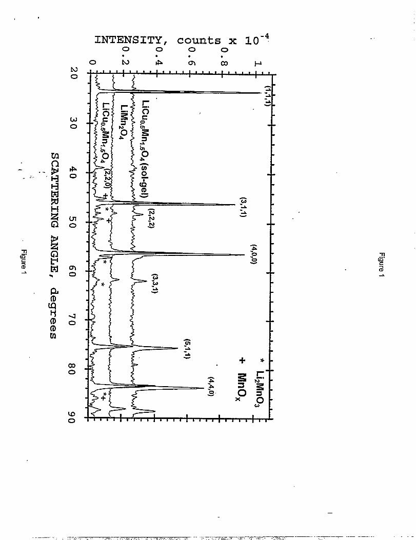
methods produced purer materials. The X-ray diffraction patterns of typical products (obtained
with Fe ~ radiation) made by the two routes are shown in Figure 1. Three subsequent firings of
the products made by the solid state reaction route reduced only marginally the MnzOJLizMn03
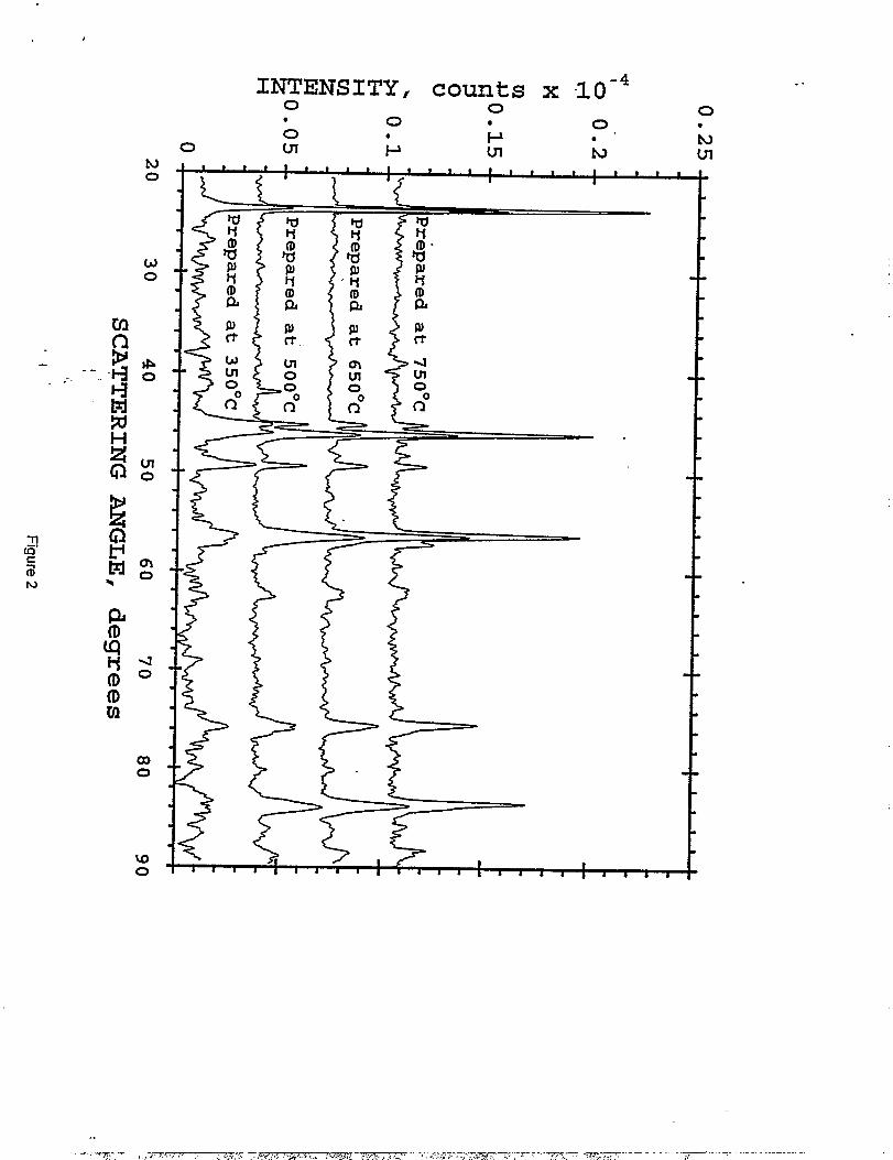
impurity levels. For the sol-gel route, the powdered precursor described in the Experimental
section above was divided into four lots; they were heated for 18 hours in air at 350°, 500°, 650°,
and 750°. C, respectively. Figure 2 shows the X-ray diffraction patterns of LiMnl.~C~.~Oq
samples after the first firing step at various temperatures. Even at a preparation temperature of
350° C, there is evidence of spinel formation, although Mnz03 is still prevalent as an impurity
phase at this temperature. At higher temperatures, the impurity levels of Mnz03 decrease; the
spinel peaks sharpen and increase in intensity, indicative of an increase in cxystallinity. Note that
LizMn03. appears only in the 750 ‘C sample in very minor concentration.
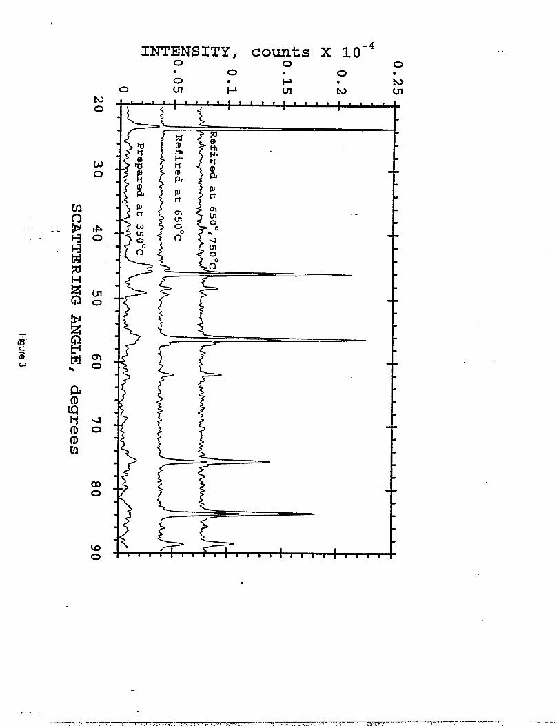
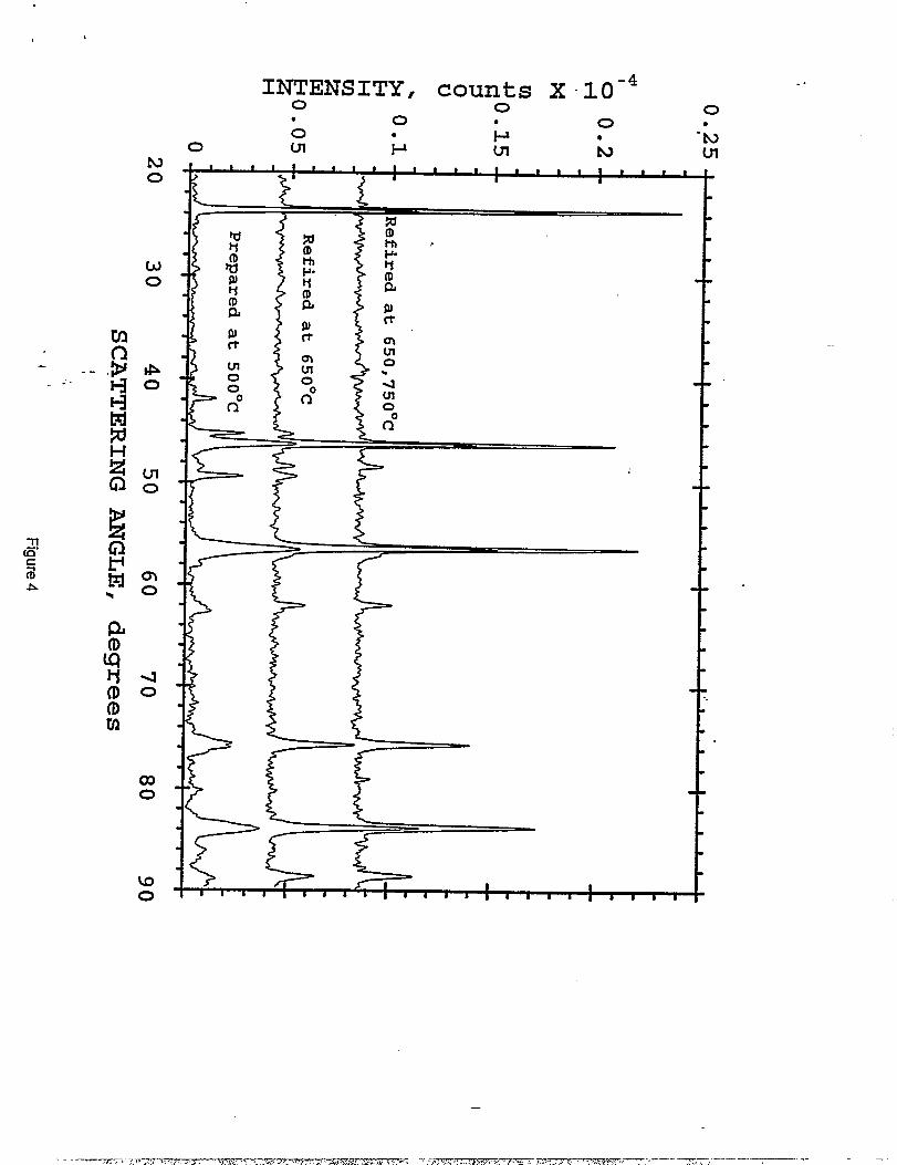
The LiMnljC%,50J samples prepared at 350 ‘C and 500 “C were each subsequently -”
refired at 650° and 750 “C. The X-ray diffraction patterns of these materials are shown in
Figures 3 and 4, respectively. Refiring at 650 ‘C resulted in the incorporation of most of the
unreacted manganese oxides into the spinel structure; a final 750 ‘C soak was necessary to
complete the reaction. This firing sequence produced what appeared to be essentiality phase-pure
materials (Figures 1 and 4); the X-ray data show a small, but significant [220] peak at 39° 2C1.
The intensity of this peak indicates that a small amount of copper resides on the 8a tetrahedral
-si~e;of the spinel structure.
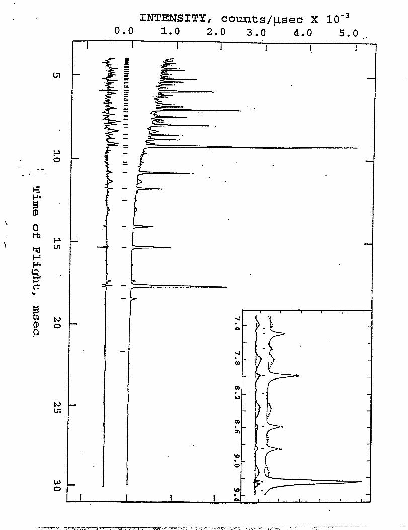
The neutron difiaction pattern of a LiMnl$~C~-~Oqsample is shown in Figure 5. The
data show clear evidence of a spinel phase (solid line) and an impurity phase (dotted line). The
peaks of the impurity phase are also highlighted by ~ expanded region of the data (inset in
Figure 5) and the difference profile, shown below the neutron diffraction pattern, which was .
obtained by subtracting the spinel peaks from the pattern. The composition of the spinel
component in the sample as determined by X-ray diffraction analysis (described in a following
section) indicated that the impurity phase was a lithium-copper-oxide compound. The
appearance of the impurity only in the neutron difllaction pattern was attributed to the fact that
copper is a very strong scatterer of neutrons (b=O.78xl 0“’2@. The observation of the impurity
phase only in the neutron diffraction pattern highlights the possible dangers of misinterpreting X-
ray ditiaction patterns.
Electrocfternica[ studies
The potential limits that were used for the electrochemical cycling of Li/LiMnz.XC~Oq
cells were 3.3 -5.1 V. In general, the charge capacity of the spinel electrode exceeded the
.
7
.— , :.T-7,W? . ... .,,.- ..r< .. ~~z..:f-,.~—---=--+ ,.,,.. ,,--—,mmm > ,--- . . .“. . . . . . . —
_e. —-.
-----T- ,.. . . .. . . ‘ .
* I
discharge capacity by 5- 10% on the first 10 cycles; this coulombic inefficiency was attributed “<
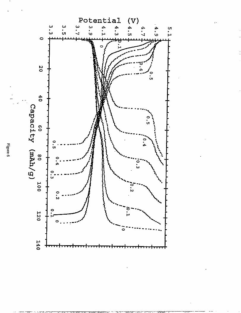
to slight electrolyte oxidation at the higher potentials. Figure 6 shows the voltage profiles
obtained for the various Li/LiMn2.XC~OJ cells (Os xs 0.5) during the third cycle. The total
capacity of LiMi2.XC%04 electrodes drops with increasing copper content from 119 mAh/g at
x=O.1 to71 rnAh/g atx=O.5.
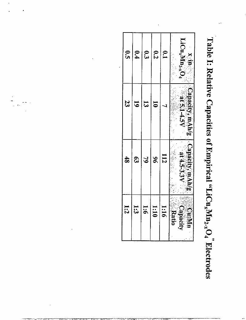
TabIe 1 summarizes the relative amounts of capacity obtained in the high voltage region
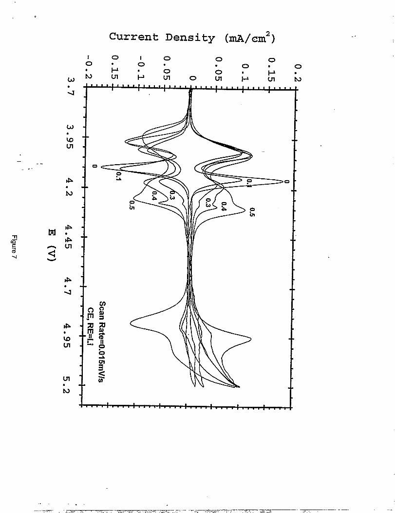
- (5. 1-4.5 V) and low voltage region (4.5-3.3 V) during the third discharge. Figure 7 shows the- ..
. -cyclic voltarnmograms of the spinel series. Note that the spinel composition with the lowest
copper content (LiMnlegCuo.l04) provides a voltage profile and cyclic voknrnogram which
closely resembles those obtained from standard LiMn204 (14). As the copper content of the
.spinel increases, the peaks which are located at 4.05 and 4.16 V in the cyclic voltamrnogram of
LiMnz04, (attributed to a two-step extraction of lithium from the tetrahedral 8a sites), shift to .
higher voltages. The higher voltage peak splits into a doublet. These features are particuhirly
noticeable in the LiMnlajC~.504 sample in which the higher voltage peak (at 4.16 V in
LiMn20A) is shifted and split into two peaks at approximately 4.22 and 4.30 V. Although the
reasons for this behavior are not yet fi.dly understood, it is believed that the peak shifls are
associated with the presence of some copper on the tetrahedral sites of the spinel structure. It is
possible that one of the higher voltage peaks of the doublet maybe due to oxidation of the
lithium-copper-oxide impurity phase. The high voltage reaction at 4.9 V that increases with
increasing copper content is attributed to the oxidation of CU2+to CU3+on the octahedral (16d)
sites of the spinel structure. The cyclic voltamrnograms indicate that all these reactions appear to
be reversible, at least on the first cycle.
8
.
J
It is clear that copper substitution has two major effects on the electrochemistry of the -.
spinel electrode that can be interpreted in terms of the coordination and oxidation state of the
copper ions. If mimicked Amine’s nickel-substituted analog, Li[Mnl.jNio.j]04, (16), the copper
ions would all be divalent and the manganese ions would be fully-oxidized in a tetravalent state.
In this circumstance, no charge capacity would be expected in the 3.9- 4.3 V region, which
originates from Mn 3++ Mn 4+oxidation; if the 4.9 V plateau was attributed to CU2++ CU3+
oxidation, then a maximum capacity of 70 mAh/g would be expected at this voltage. The
ele~~ochemical data shown in Figures 6 and 7 is clearly inconsistent with a spinel electrode with
the simple cation arrangement in Li[Mnl.5C~.J04; the data imply a different cation arrangement
and charge distribution in the structure of the spinel electrode. The relatively large capacity that
is obtained between 3.9 and 4.4 V for LiMnz.XC%04 compounds with small x is associated with
a large Mn 3+concentration on the octahedral sites (Table 1). The relatively low capacity that is
obtained at 4.9 V but which increases with increasing x, and the fact that the overall achievable
capacity declines sharply with increasing x is consistent with increasing Cu 2+and Mn4+
concentrations in the spinel samples.
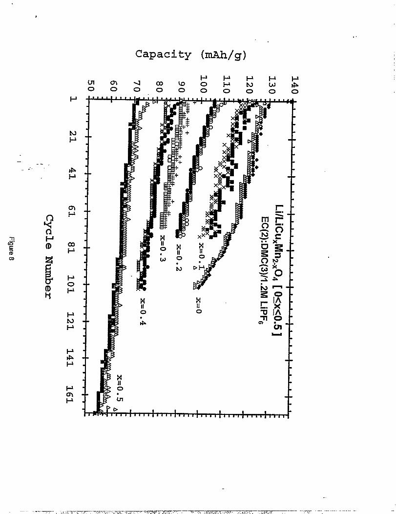
Figure 8 ‘shows the cycling petiormance in terms of discharge/charge capacity obtained between
5,1 and 3.3 V, expressed in mAh/g, VS.cycle number for the series of LiMn2.XC~Oq electrodes
(Os xs 0.5). The available capacity decreases as the amount of copper in the spinel increases.
However, electrodes with higher copper content showed significantly improved capacity
retention on cycling. For example, Li/’’LiMngCuou104°4° cells show on average, an initial
capacity of 120 mAh/g which decreases to 103 mAh/g after 70 cycles, reflecting a 14°/0loss,
9
..—~-- ..T. :...L ., - . . . ,,, , ,.\, <m,. ..... “,, . . .. . . -. . . ...) -> ..,-. . . . . .-——
.-
a t
whereas Li/’’LiCuO+5Mn1<50J”cells show an initial capacity of 71 mAh/g that fades to 65 mAh/g“‘
over the same number of cycles (8°Aloss).
X4A?ES measurements
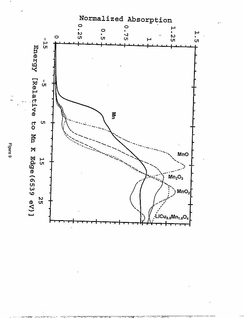
Figure 9 shows the XA.NES spectra at the Mn K edge for Mn, MnO, Mnz03, MnOz and
LiMnl.5C~+50~. The MnOz spectra were obtained from a chemically-prepared MnOz sample
(CMD). Data for electiochemicaIly-prepared MnOz (EMD) are aImost identical. The XANES “
- data. for LiMnI.5C~.50A (dotted Iine), which show a shouIder on the main peak at 11.5 eV, are.. -
consistent with the presence of both Mn4+and Mn3+,implying that Mn3+exists in a relatively low
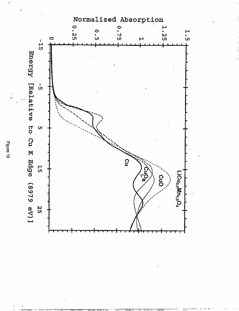
concentration in the spinel structure. Figure 10 shows the XANES spectra at the Cu K-edge for
Cu foil, CUZO,CUO and [email protected]. The spectrum for CUO has a distinct shoulder at 8 eV.
This is due to the distorted octahedral coordination of Cu. Each Cu is surrounded by four planar
O atoms at a distance of 1.96 ~ and two axial O atoms at a distance of 2.78 ~. The shoulder at 8
eV has been attributed to transitions from the 1s state to the axial 4P states, and the peak at 18 eV
to transitions to the pkinar 4P states (23). In a more symmetrical coordination such as an aqueous
solution of CU2+the shouIder at 8 eV disappears, but the position of the white line peak at 18 eV
remains unchanged (23). Theoretical calculations predict that for CU3+the white Iine should shift
by 10 eV in going from CU2+to CU3+(24). Measurements on KCUOZ,in which the CU3+ions
have square planar coordination to neighboring, show a peak shift of only 4 eV (23). Since no
shift is seen in the peak, and there is no shoulder in the edge, the XANES data would appear to
indicate only CU2+ions with a symmetric coordination.
10
- -=T,=-, . . . ... ., Tw--/ .*, . . ..r9--r9--’?r. . . . . . . . . . ........m.. . . ..—
.——- -.
Structure Refinements . .
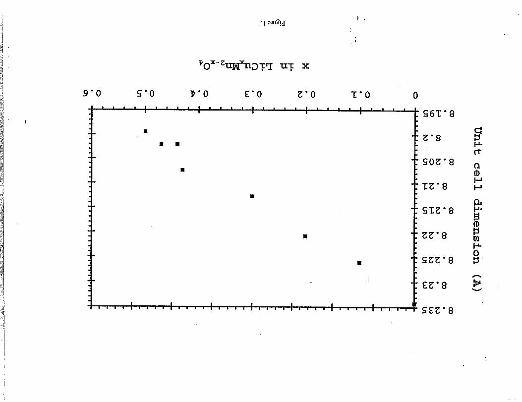
The lattice parameter, a, of LiMnz.XC~OAspinel structures, decreases with increasing x,
horn 8.234A in LiMnzOd (x=O), through 8.2 12A in “LiMnl.7C~.30J’ (x=O.3) to 8.199 ~ in
“LiMnl,5C~.~Oq” (x=O.5) (Figure 1I); this trend is characteristic of an increasing concentration
of Mn4+ ions in the spinel structure which results from the substitution of Mn3+ions by CU2+
ions.
- .. In a spi.nel structure with the cation distribution Li~l.~C~.~]04, charge neutrality is
obtained when the manganese ions are all tetravalent and the copper ions are alI diwdent.
Replacement of copper by lithium on the octahedral sites results in Li@fn~012 (or in spinel
notation Li[Mnl-67Lio.33]04) in which charge neutrality is achieved by increasing the Mn4+
content to compensate for the monovalent lithium ions. These two compounds are, in principle
the end-members of a possible solid solution system Li~l.5+XC~.5.3XLi2J04 (OSXSO.167). In
this solid solution system, it would also be possible for lithium and copper ions to exchange on
the tetrahedral sites. Structural refinements of such complex systems are difficult, particularly
when three different cation-types are disordered over one crystailographically independent site.
Despite the difficulties that were encountered in obtaining a meaningful fit to the neutron
diffraction data of a two-phase reaction product, these analyses provided valuable information
about the structure that couId not be determined born the X-ray diffraction patterns. This
itiorrnation was then used for the finaI structure refinement with the “single-phase” X-ray
diffraction data. The structure was refined using the prototypic cubic spineI space group Fd3rn.
11
Stmc~emalyses of thespinel component in~oindependent-Li~ l.jCuOo5Oqsmp1es ““
using neutron diffraction data from Argonne National Laboratory and the Rutherford Laboratory
showed unequivocally, and consistently with various models, that some copper occupied the 8a
tetrahedral with a site occupancy of approximately 0.1. Furthermore, refinements of various
models showed consistently that between 1.64 and 1.71 Mn occupied the octahedral B sites of
the A@JOJ spinel structure. A site occupancy of 0.835, corresponding to an average 1.67 Mn in
the [BJOq spinel framework was, therefore, used for the refinement of the X-ray data. It is,
per!iaps, significant that this vaIue corresponds to the Mn content in LiJvln501z
The initial refinements of the X-ray data showed that the intensity of the [220] peak at
approximately 310 X3 could not be accounted for by placing only lithium on the tetrahedral sites,
consistent with the neutron data. Subsequent refinements were, therefore, carried out on the .
system (LiOegC~,l) [email protected]~.ssJjLi~]lc@A~ using the input from the neutron data. The
parameter, 6, lvas used to control the stoichiometry of the lithium and copper on the 16d
octahedral sites. A second parameter, cx,was refined to determine if there was any non-
stoichiometry in the oxygen content. Because of the limited number of the reflections (intensity
data), isotropic temperature factors (U) were assigned to aIl the ions. The cations were
constrained to have the same U vah,xe.
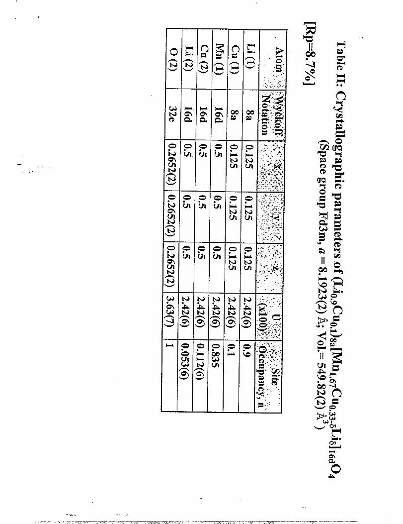
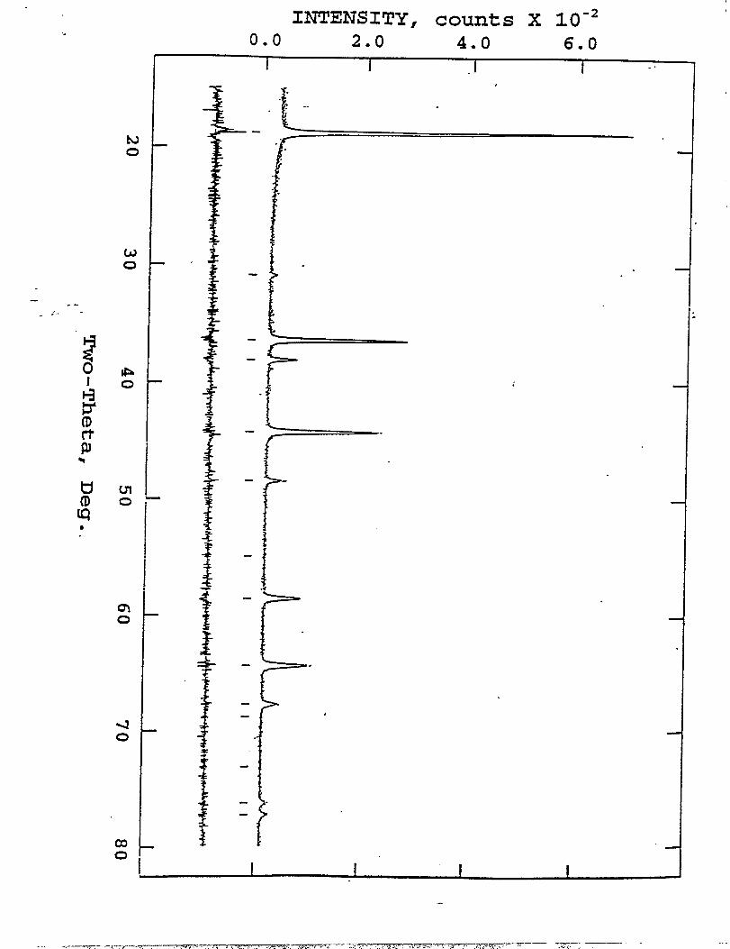
The results of the refinement which yieIded the best fit to the data (RP=8.7%) are
summarized in Table 2. The observed and calctdated powder X-ray diffraction profiles of the
spinel component in the LiMnl.jCuo,504 sample for this refinement are shown in Figure 12. The
12
I
I
#
lattice parameter refined to 8.1923(2) ~. Refinements of two separatesamples did not favor an -”
oxygen-deficient structure; both refinements showed that the oxygen ion positions were filly
occupied (ct=O). The structure analysis showed a cation distribution
(LiO.gCuO.l)g.ml.b7C%.z2Li0.ll]lbdOd; the overall composition is Lil.olMnl.6TC~.3zOd.
Assuming that all the copper is divalent, then the oxidation state of the manganese ions is 3.80;
this finding is consistent with the XANES data that indicated only a small Mn3+ion
concentration in the “LiMnl.5C~.504” samples.
. ..---- -
A spinel eIectrode with the composition @iO.~C~o~)g,~~.b~C~.z~LiO.*l]~@~ would have
a theoretical capacity of 95 mAh/g, corresponding to the extraction of 0.65 Li+ ions and the
complete oxidation of 0.33 mole fraction Mn3+to Mn4+and 0.22 mole fraction CU2+to CU3+.
The capacity associated with the manganese and copper ions on the octahedral sites is 48 and 32. .-----------
nAh/g, respectively, which is in good agreement with the capacities of 48 and 23 @g -
obtained from this electrode in an electrochemical cell (Table 1). The experimentally achieved
capacity reflects, therefore, a 75% utilization of the theoretical capacity. The possibility of
exceeding this capacity appears to be limited because it is anticipated that the oxidation of CU2+.
ions on tetrahedral sites would occur at a voltage >5 V which is above the stability window of
the electrolyte.
If all the manganese present in the precursor materials was used in the fabrication of the spinel
structure, as implied by the repeated firings required to completely react the manganese oxides
(Figures 3 and 4), then the composition LiI.oIMnl.67C~.3z04 indicates that 9% of the lithium and
42’?40of the copper in the precursor materials were not incorporated into the spinel framework.
13
This result strongly suggests that the impurity detected in the neutron.diffraction profile is a -.
lithium copper oxide phase. Although several lithium copper oxide compounds areknownto
exist, particularly Li20*nCu0 compounds with divalent copper,
Li2CuOz (n=l) (26), none of these compounds could be indexed
the impurity phase in the neutron difliaction pattern.
such as Li2Cu203 (n=2) (25) and
satisfactorily to all the peaks of
Morphologic! characterization of Liiktn2.XCuXOdspinek..
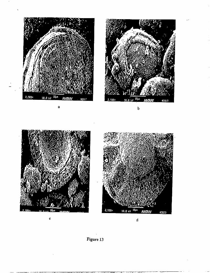
. .. . Scanning electron micrographs of spinel sampIes in the LiMn2.XC~OQseries.-
(Os x< 0.5), prepared by solid state reactions, are presented in Figure 13(a-d). The products,
which include the standard, unmodified LiMn20A spinel (x=O) (Figure 13a) all possess an onion-
Iike microstructure with an approximate 2 ~m ring thickness. These onion-like structures can be
expected to be subject to cracking and exfoliation during electrochemical cycling, unless the
“breathing” that is expected to occur during lithium intercalation and deintercalation can be .
minimized. At this stage, the extent of morphological changes (and variations in lattice
parameter and crystal symmetry) of the copper-substituted spinels that occur during lithium
extraction and insertion reactions is unknown. Further work is being planned to monitor the
changes in crystal morphology of these structures to long-term electrochemical cycling.
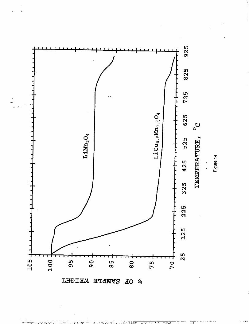
Thermo-gravimetric anaiysis of LiMnl.5Cu0.504 under hydrogen
Thermogravimetric analysis measurements were conducted to investigate the thermal
stability of LiMnl.~C~,50q relative to LiMn20Qunder reducing conditions (H2) (Figure 14); the
data show significant differences, both in the onset temperature and the degree of reduction. The
14
reduction of LiMn20A that occurs through oxygen loss is initiated at approximately 140 ‘C; over “”
the next 200 ‘C, the sample loses 9.6% of its weight. Following a Iengthy period of minimal
weight loss, the material undergoes a further weight loss of4.6°A from 8200 to 900 ‘C. The
first reduction process corresponds to the removal of approximately one oxygen atom fi-omthe
spinel formula unit, resulting in “LiMn203” (the theoretical weight loss for this reaction is 8.90A).
The total weight loss of 14.2’XOcorresponds closely to the formation of “LiMnz02.5”,
alternatively “Li20”4MnO” (the theoretical weight Ioss for this reaction is 13.30A).
. ..-.
Inclusion of copper in the spinel fh.mework dramatically increases the reactivity towards
hydrogen. Onset of weight loss was almost immediate, and by 230°C, the LiMnl.~C~.~Og
sample had lost 26’XOof its weight, indicating that the residue had the empirical formula
LilMnl.5C~,501m0.Subsequent heating to 900 “C resulted in an additional 3.5% weight loss,
mostly above 750 “C. The result indicates that the reduced product of LiLhl.5C~.50Q at 900 “.C
is comprised essentially of metallic Cu and Mn, and Li20 (the theoretical weight loss for the
reaction is 30.20/o); moreover, the result demonstrates that the presence of copper in the spinel
greatly facilitates electron transfer within the spinel framework which, at moderate temperatures
(200 0-300 “C), leads to an almost complete reduction of LiMnl.5C~.~Og.
Conclusions
Novel electroactive materials, LiMn2.XC%OQ,(0.1 ~ xs 0.5) have been prepared and
evaluated in lithium cells. The data show that lithium can be extracted from the spinel
structures in two main potential regions: 3.9 to 4.3 V and 4.8 to 5.0 V, attributed to the oxidation
15
.. ,-> ,,-...$-,7-- ~...,- . , >. ,--- , .> ,.&w,..W . . . . . . .,>,.,.W , , ..—* ,., ,. .. ,...,, ~<, ., . . . . . . . . ,, . . . ,.. . -.
. . .
.
.
of Mn3- to MnJ+ and Cu 2+to CU3+,respectively. The reactions are reversible. Stable. .
electrochemical cycling has been observed for electrode compositions with high values of x, but
with low capacity (60-70 mAh/g), for example, in an electrode with overall composition
“LiMn10~C~c50q”(x=O.5). Analysis of X-ray and neutron diffraction data, and XANES spectra
have revealed that it is diflicult to synthesize single-phase lithium-copper-manganese-oxide
spinel compounds with a predetermined composition. The stability and relatively low reactivity
of CUO (compared to Li20) appears to restrict the complete incorporation of copper into the
. .. .‘spinel structure. The cation distribution in these spinel structures is highIy complex, which
makes it difficult to perform detailed structure analyses with X-ray and neutron difiiaction data .
with a high degree of accuracy. Although the XANES data show that the oxidation state of
copper in these spinel compounds is divalent, the possibility of a small amount of Cu 1+(in
tetrahedral sites) or CU3+(in octahedral sites) in the starting spinel structures should not be
entirely discounted. In-situ XANES and X-ray diffi-action experiments are being planned in
order to obtain firther information about the structural properties of these spinel compounds.
Acknowledgments
This work was performed under an SBIR Phase I DoD program sponsored by the U.S.
Army CECOM, administered by the Army Research Laboratory, Fort Monmouth, NJ, under
Contract No. DAAB07-97-C-D304. Support for Argonne National Laboratory from the U.S.
Department of Energy’s Advanced Battery Program, Chemical Sciences Division, OffIce of
Basic Energy Sciences, under Contract No. W-3 1-109-Eng-38 is gratefi.dly acknowledged. Dr.
W. L F, David and Dr. R. M. Ibberson are thanked for collecting neutron diffraction data at the
16.-
- m.:- -’. ~-!,-, . -. ,. ,<!. .-WZTT?.+ 3. ;. Tii’.7.=r=-7”--~~-~’. ‘ , ‘“-.” ‘.
;,~ ..,~<~~------- -—.—.——— -. —.
-m

.
,
Rutherford Appleton Laboratory and for undertaking some preliminary structural refinements. “”
The authors would like to thank Mrs. J. H. Hemenway and I’vfr.R. Laura for assisting in
manuscript preparation and Professor. J. B. Goodenough for stimulating discussions.I
.-,., ----
17
I
References
1.
7-.
3.
4.
5.
..-.
6.
7.
8.
9.
J. R. Dahn, T. Zheng, Y. Liu, and J. S. Xue, Science, 270,590 (1995).
R. Yazarni, presented at 12th Int. .Seminar, Primary and Secondary Battery Technology
and Applications, Deerfield Beachi FL, 6-9 March 1995.
Y. Idota, T. Kubot~ A. Matsufu..i, Y. Maekawa and T. Miyasaki, Science, 276,1395 (1997).
J. B. Goodenough, D. G. Wickham, and W. J. Croft, J Plzys. Chenz.Solids, 5,107 (1958).
K. Mizushima, P. C. Jones, P. J. Wiseman, and J. B. Goodenough, Mat. Res. Bull., 15,783
..-.(1980).
E. Plitcha, M. Salomon, S. Slane, M. Uchiyam~ D. Ch~ W. B. Ebner, and H. W. Lin, J.
Power Sources, 21,25 (1987).
J. R, Dahn, U. von Sacken, and C. A. Michal, Solid State Ionics, 44,87 (1990).
A. Lecerf, M. Broussely, and J. P. Gabano, US. Patent No. 4980080,1989.
T. Nagaura, JEC Battery Newsletter, No. 2 (Mar. - Apr.) (1991).
10.ITE Battery Newsletter, No. 6 (Nov. - Dec.) (1996).
11.M. M. Thackeray, J%omess in Batteries and Batterv Materials, Vol. 14, R. J. Brodd, cd., ITE
Press, Inc., Brunswick, OH, p. 1 (1995), and references therein.
12.R. J. Gummow, A. de Kock, D. C. Liles, and M. M. Thackeray, SolidState Ionics, 69,59
(1994).
13.G. Pistoia, C. Bellito, and A. Antonini, 190th Electrochem. Sot. Meeting, San Antonio, TX,
6-11 October 1996.
14.A. D. Robertson, S. H. Lu, and W. F. Howard, Jr., J Electrochem. Sot., in press.
15.1.J. Davidson, R, S. McMillan, and J, J. Murray, US. Patent No. 5370949, 1994.
18
,
16.K. Amine, H. Tukamoto, H. Yasuda, and Y. Fujita, 188th Electrochem. Sot. Meeting,
Chicago, IL 8-13 October 1995; K. Amine, I-LTukamoto, H. Yasuda, and Y. Fujita, J
Electrochem. Sot., 143, 1607 (’1996).
17,C. Sigala, D. Guyomard, A. Verbaere, Y. Piffitrd and M. Tournoux, Solid State Ionics, 81,
167 (1995).
18.Y. Gao, K. Myrtle, M. Zhang, J. N. Reimers, and J. R. Dahn, Phys. Rev. B, 54,3878 (1996).
“19.Y. Ein-Eli and W.F. Howard, Jr., J Electrochem. Sot., 144, L205 (1997).
=20.K.I. Pandy~ R.W. Hoffi-nan, J. McBreen, and W.E. O’Gradey, 1 Electrochem. SOC.,137, 383
. .
(1990).
21.J. Wong, F.W. Lytle, R.P. Mssmer, and D.H. Maylotte, Phys. Rev., B 30,5596 (1984).
22.A.C. Larson and R.B. Von Dreele “GSAS-GeneraI Structure Analysis System”. Rept. LA-
UR-86-748, Los Alamos National Laboratory, Los Alamos, nm 87548,1990.
23.J.M. Tranquad~ S.M. Heald, and A.R. Moodenbaugh, l’hys.l?ev., B 36,5263 (1987).
24.E.E. AIp, G.K. Shenoy, D.G. Hinks, D.W. Capone II, L. Soderhohn, H.B. SchuttIer, J. Guo,
D.E. Ellis, P.A. Montano, and M. Ramanathan, Phy.s.Rev. B 35,7199 (1987).
25.JCPDS Data File 36-661.
26.J. Barker and M. Yazid Saidi, U.S. Patent 5,670,277 (1997).
19
-“ - ‘-?-m- . ,-~:;-;~,,. ,. $“ -?,~===~=-7$
.- —— -- .- . . .._
.. ,,.,. ,A..,. ...-— —-——~—— ———, ,. .-., , .>-.,,, T+.<. , , ., > +
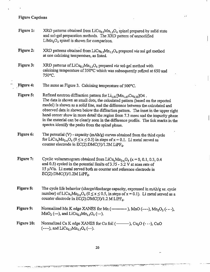
Figure Captions
Figure 1:
Figure 2:
Figure 3:
- Figure4:. .
Figure 5:
Figure 6:
Figure 7:
Figure 8:
Figure 9:
Figure 10:
XRD patterns obtained from LiCuO~Mnl.~Oqspinel prepared by solid stateand sol-gel preparation methods. The XRD pattern of unmodifiedLiMnzOJ spinel is shown for comparison.
XRD patterns obtained from LiC~.~Mnl.~Od prepared via sol gel methodat one calcining temperature, as listed.
XRD patterns of LiCuO#lnl.~OQ prepared via sol-gel method withcalcining temperature of 350”C which was subsequently refired at 650 and750”C.
The same as Figure 3. Calcining temperature of 500”C.
Refined neutron diillaction pattern for Lil.ol~l.GTC~.3z]04 .The data is shown as small dots, the calculated pattern (based on the reportedmodel) is shown as a solid Iine, and the difference between the calculated andobserved data is shown below the difliaction pattern. The inset in the upper righthand comer show in more detail the region from 7.3 msec and the impurity phasein the material can be clearly seen in the difference profile. The tick marks in thespectra identifi the peaks from the spinel phase.
The potential ~ - capacity (mAh/g) curves obtained from the third cycIefor LiC~Mnz.XOq (Os xs 0.5) in steps of x = 0.1. Li metal served ascounter electrode in EC(2) :D,MC(3)/1.2M LiPFb.
Cyclic voltarnmogram obtained from LiCuXMnz.XOx(x = 0,0.1,0.3,0.4and 0.5) cycled in the potential limits of 3.75 -5.2 Vat scan rate of15 pV/s. Li metal served both as counter and reference electrode inEC(2) :DMC(3)/1 .2M LiPFG.
The cycle life behavior (charge/discharge capaci~, expressed in mAh/g vs. cycIenumber) of LiCu.#fn2.X04 (Os xs 0.5, in steps of x = O.1). Li metal served as acounter electrode in EC(2) :DMC(3)/1.2 M LiPFG.
Normalized Mn K edge XANES for Mn ( ), MnO (---), Mnz03 (- - -),Mn02 (---), and LiC~.#fnl.~04 (....).
Normalized Cu K edge XANES for Cu foil ( ), Cu,o (- - -), Cuo
. .
,
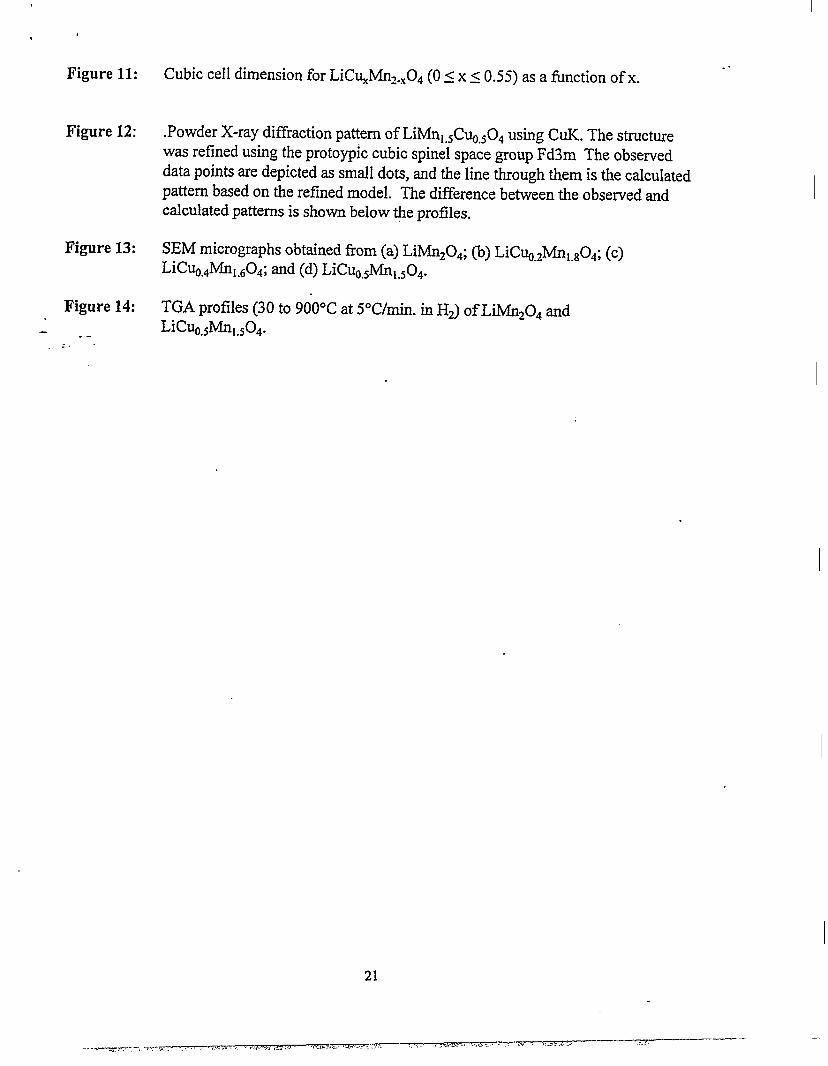
Figure 11: Cubic cell dimension for LiCuXMnz.XOA(Os xs 0.55) as a function of x.
Figure 12: .Powder X-ray diffraction pattern of LiMnl.~C~.~OQusing CUK. The structurewas refined using the protoypic cubic spinel space group Fd3m The observeddata points are depicted as small dots, and the line through them is the calculatedpattern based on the refined model. The difference between the observed andcalculated patiems is shown below the profiles.
Figure 13: SEM micrographs obtained from(a) LiMn204; (b) LiC%.zM1.sog; (c)LiC~,4Mnl.G01; and (d) LiCu@nl.~04.
Figure 14: TGA profiles (30 to 900”C at 5°C/min. in H2) of LiMnzOd andLiC~.#lnl~04.--
---
21
. .
.
. .
.-.....
#
.-. =.
c‘N
0m
0CA
.0Cn
“Nul
0
NW
I
.. .. .... ,.:....--.. . .:.
Z&-’‘:”g.:j.y’
.“” . ...
%+:.$:”;-..:,....~,.... . +..:,.........::.::...?.!!;:.,:.,:.’;....... ..
‘g: ~:j;:<.-.
Sf$
Sa~.’,. .
~,”:.
. . .
+: .’
. .
wzHH● 0
. !,, . --. ,
.. —-+= . . . .. :;,-=, ,. ... far------ ,-:.--—. -,,.. ., . . . . ,. +.,. .-. .,>,.,. ~,-. . . . . ,. .-—.
, . . .. .. . -=—--Y-73. . ---- ,,
...-
.-..
501?El
INTENSITY, counts x 10-4
-- L
L
. .
—
n-.mr=aA
#
IQ
m
mo
t
. ..
-n-.cocz
,-. .
wo
I@o
INTENSITY, counts X 10-40 0 0● o ● o ●
● ●
o : I-J E N K
—
H--k %-s
r
. .
..—f, ,,-, ------- _—— —~.— -— ——. -
INTENSITY, counts X ~10-4 . .
.-
.A
N0
w0
lb0
w0
m0
40
CQ0
w0
0 0● 0 00 0
●
0 UI LI-J
-Lul L (n
>
-.
-TC7-,- -, ,, T-l ,., ,,, >, ,. . . . . . . . . . .. . .. . . . .. . . . ., ??2 ,7--- -.-— --—- -—-—— ~-- --
m
MUI
w0
INTENSITY, coun~S/~Se~ X 10-30.0 1.0 2.0 3.0 4eo 5.0 . .
.
.
1
=+
= .
. .
I I I
—$ - --- ~TT.rm7--, . , . . . -.., . . . . .,
~, ,r..,= ,, . --e. -, ., , ... =.,....., . -, , ,-+ .—- :5., -..——-.
-.-Tr- ,.-.,..
o
A.... 0,. :-.
c1PwD(lCnp. o
.
.
.
.
0● ,-ul
0 ● .4. * , ----
1
/’
r
i
1. ------
------
)1 s:,,,,:,,,,:,,.,:, ,,, :,, ,,:, ,,,1 I# # a * s * # 1-
.. —m-. . .. -—.-.?----wr-w-- “,.,...................,,7--.., . . ,5. . . -—. ---TX-F.?.. -, <$ -.-v?..,,— , ,,~. . . . ----
. .---
-n-.(ncd-1
Current Density (mA/crn2)
t
%
w +
/’4 . . . . . . . . . . . . . . . . . . . . . . . . . . . . . . . . . .:>.,c~
. .
.,, .m. ,-——-V7Y7- 7-WY- . . . .. ~. . .. --m . , . ,.. f . . ..(, .,,J...-73?T7-=7-=-- -Y -- .,..< .J, r> -,. ?’ ., -=. x —. .— - .—,,, ,
. ...
.
—.-. .—. = - -:.,..,7-,j. . ., .,, , ,./,.<, ,,,.. , -. ,,JC !,, .,, ,., .,. —~.—”--wTrw2:+:+. ;.....* L- ‘. .:.>--- .-,--~ —-y~---—— —- .- —- --. . . ... . , ., ,..,., .s .-
‘a
u
.
.
.
. .
—
..-— -..-, .. . ... ....~,nv- 77--. -.:-,-- v, .,, ,.. ..,.TY-TF, . ,.,, ,’-T- . . . . . -! .. . . . . . . . . . ,.-. vm...’-vm.-. {,. ff * —-q7---
.
-l-i(g’iii
1?
%
u
Normalized Absorptiono 0 P● o ● ● P
● 4~“
●
o UI w w E w
1
.-
=,- -,.. --.-7 , ,. ,. . ..., ,, .,2.,,,. . ,. -, ,,,, +&, ,$ .\.,...,, ,.,-, — . . . . ~, ‘.!7? .,.>,. ,---,. ..,, >,. ,.-:--. .— . . .
. ...%%.>> .- ‘“ +.,:. .— -
I.
“1$..1..
I
9“0 S*O
■ ■
?“0 E“o zoo
■
Too
■
I
o
S6T”8
2“8
S02”8
TZ”8
STZ”8
22”8
S22”8
EZ”8
SS2”8
g
P“
09“
INTENSITY, cmmts X 10-20.0 2.0 4.0 6.0
. .- ---- -
Na
wo
lbo
mo
2
40
alo
.
.
,
#
~.0
.
. .
1 I I
-.—- ,-,—=-v . . . . -4. ---- . ., . . $ ..>. .-4..>. . . . . . . . ---J-- ,.. . w.>-. ....-=-..7-=7-% ,. ,,? .’... -’ .- ,.—.- .+, ,,,
. .
a b
c d
Figure 13
——m -. .,,. .,., —--- . ,, . . . ,. . . . . . . . . . ..,-?r’r- . . . . . . . > -nz?,=’---iT.i---- -— —-...,. .
. .
. .
Lnmm
/’.- .-I r
““l+
mCN*
+ /
iLHD13M 3’Iarw do %