linde briefing for usea linde...fired power plant incorporating linde-basf pcc technology. ......
TRANSCRIPT
Linde Briefing for USEA Update on DOE Post-Combustion Capture project & CCUS activities
January 2013

04/02/2013 2
Linde Overview & Focus on CCUS Pathways
PCC Technology & Update on DOE Project
Current CCUS Activities & Focus Areas
04/02/2013 3
Leveraging Synergies
3
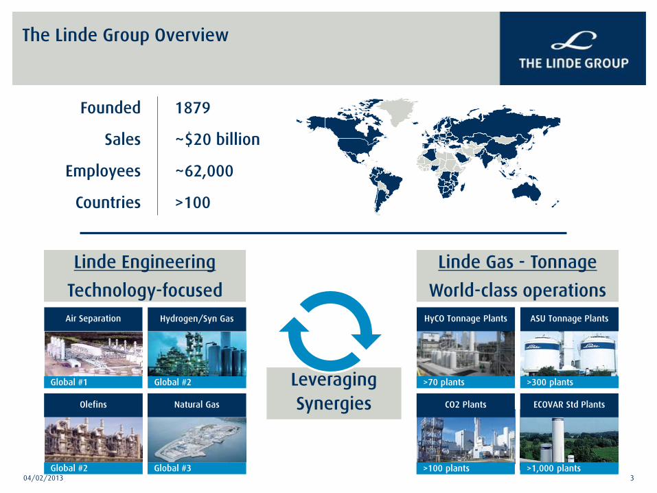
The Linde Group Overview
1879
~$20 billion
~62,000
>100
Linde Engineering
Technology-focused Air Separation
Global #1
Hydrogen/Syn Gas
Global #2
Olefins
Global #2
Natural Gas
Global #3
HyCO Tonnage Plants
>70 plants
ASU Tonnage Plants
>300 plants
ECOVAR Std Plants
>1,000 plants
Linde Gas - Tonnage
World-class operations
Founded
Sales
Employees
Countries
CO2 Plants
>100 plants

04/02/2013 4
Growth opportunities Product portfolio serving mega trends
Leveraging Gases & Engineering business synergies
Clean energy Healthcare Growth markets
04/02/2013 5
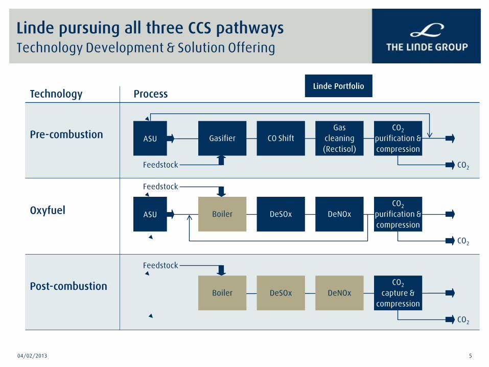
Linde pursuing all three CCS pathways Technology Development & Solution Offering
Technology Process
Pre-combustion
Oxyfuel
Post-combustion
Linde Portfolio
Feedstock CO2
Gasifier ASU Gas
cleaning (Rectisol)
CO Shift CO2
purification & compression
CO2
Boiler ASU DeNOx DeSOx CO2
purification & compression
Feedstock
CO2
Boiler DeNOx DeSOx CO2
capture & compression
Feedstock

04/02/2013 6
Linde Overview & Focus on CCUS Pathways
PCC Technology & Update on DOE Project
Current CCUS Activities & Focus Areas

Fußzeile 7
Overall Objective
— Demonstrate Linde-BASF post combustion capture technology by incorporating BASF’s amine-based solvent process in a 1 MWel slipstream pilot plant and achieving at least 90% capture from a coal-derived flue gas while demonstrating significant progress toward achievement of DOE target of less than 35% increase in levelized cost of electricity (LCOE)
Specific Objectives
— Complete a techno-economic assessment of a 550 MWel power plant incorporating the Linde-BASF post-combustion CO2 capture technology to illustrate the benefits
— Design, build and operate the 1MWel pilot plant at a coal-fired power plant host site providing the flue gas as a slipstream
— Implement parametric tests to demonstrate the achievement of target performance using data analysis
— Implement long duration tests to demonstrate solvent stability and obtain critical data for scale-up and commercial application
Project Objectives
Fußzeile 8
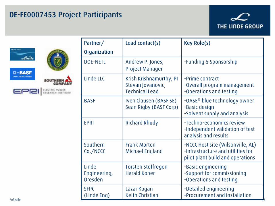
DE-FE0007453 Project Participants
Partner/
Organization
Lead contact(s) Key Role(s)
DOE-NETL Andrew P. Jones, Project Manager
-Funding & Sponsorship
Linde LLC Krish Krishnamurthy, PI Stevan Jovanovic, Technical Lead
-Prime contract -Overall program management -Operations and testing
BASF Iven Clausen (BASF SE) Sean Rigby (BASF Corp)
-OASE® blue technology owner -Basic design -Solvent supply and analysis
EPRI Richard Rhudy -Techno-economics review -Independent validation of test analysis and results
Southern Co./NCCC
Frank Morton Michael England
-NCCC Host site (Wilsonville, AL) -Infrastructure and utilities for pilot plant build and operations
Linde Engineering, Dresden
Torsten Stoffregen Harald Kober
-Basic engineering -Support for commissioning -Operations and testing
SFPC (Linde Eng)
Lazar Kogan Keith Christian
-Detailed engineering -Procurement and installation
2/4/2013 Fußzeile 9
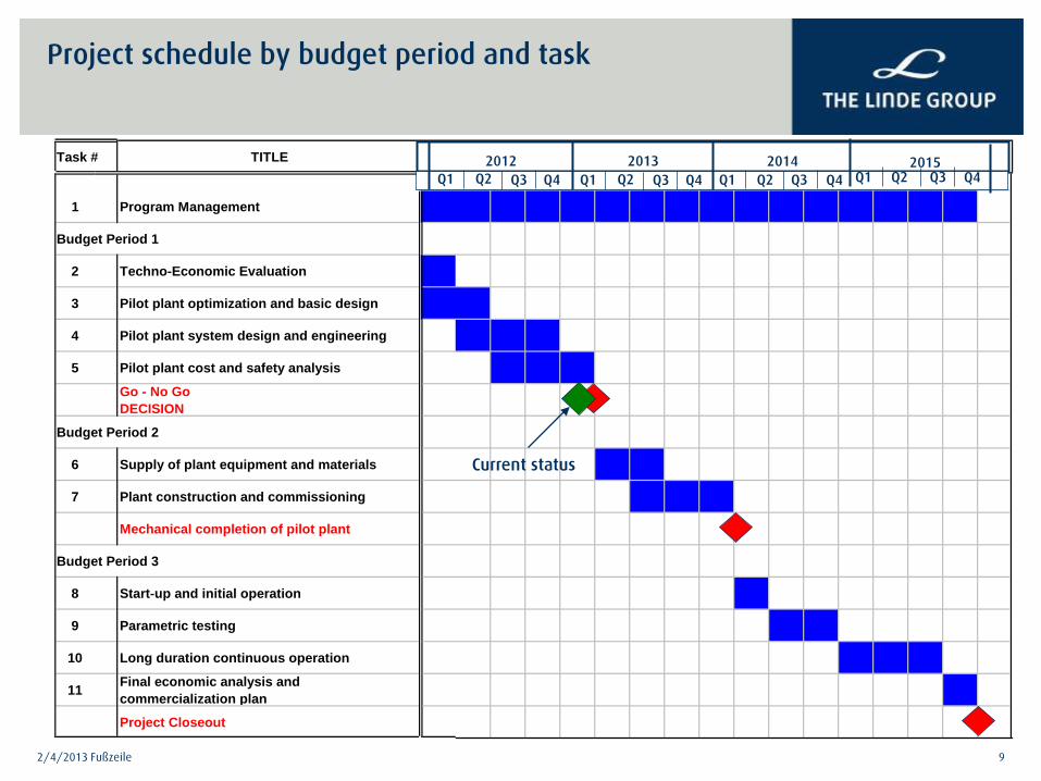
Project schedule by budget period and task
Task # TITLE
1 Program Management
Budget Period 1
2 Techno-Economic Evaluation
3 Pilot plant optimization and basic design
4 Pilot plant system design and engineering
5 Pilot plant cost and safety analysis
Go - No GoDECISION
Budget Period 2
6 Supply of plant equipment and materials
7 Plant construction and commissioning
Mechanical completion of pilot plant
Budget Period 3
8 Start-up and initial operation
9 Parametric testing
10 Long duration continuous operation
11 Final economic analysis and commercialization plan
Project Closeout
2012 2013 2014 2015 Q1 Q2 Q3 Q4 Q1 Q2 Q1 Q1 Q2 Q2 Q3 Q3 Q3 Q4 Q4 Q4
Current status
Fußzeile 10
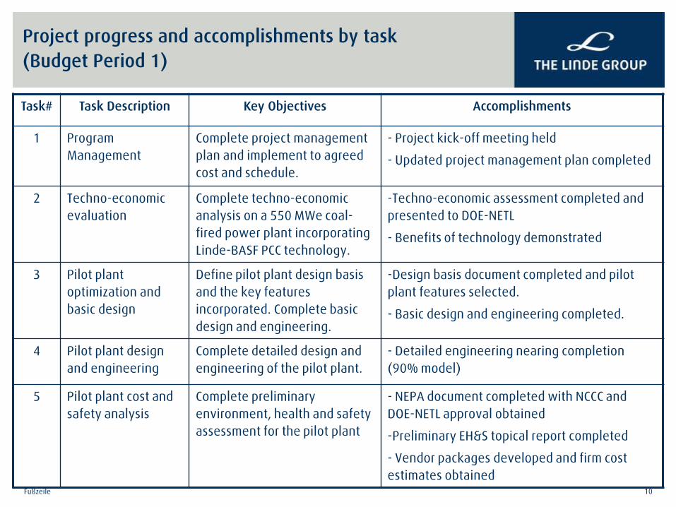
Project progress and accomplishments by task (Budget Period 1)
Task# Task Description Key Objectives Accomplishments
1 Program Management
Complete project management plan and implement to agreed cost and schedule.
- Project kick-off meeting held
- Updated project management plan completed
2 Techno-economic evaluation
Complete techno-economic analysis on a 550 MWe coal-fired power plant incorporating Linde-BASF PCC technology.
-Techno-economic assessment completed and presented to DOE-NETL
- Benefits of technology demonstrated
3 Pilot plant optimization and basic design
Define pilot plant design basis and the key features incorporated. Complete basic design and engineering.
-Design basis document completed and pilot plant features selected.
- Basic design and engineering completed.
4 Pilot plant design and engineering
Complete detailed design and engineering of the pilot plant.
- Detailed engineering nearing completion (90% model)
5 Pilot plant cost and safety analysis
Complete preliminary environment, health and safety assessment for the pilot plant
- NEPA document completed with NCCC and DOE-NETL approval obtained
-Preliminary EH&S topical report completed
- Vendor packages developed and firm cost estimates obtained

11 11
Linde-BASF experience in large scale carbon capture CO2 capture in NG processing: Re-injection Project - Hammerfest
700,000 tpa CO2 capture and re-injection (part of world scale LNG project, Snøhvit, Norway)
World’s first industrial project to deliver CO2 separated onshore from the well-stream back offshore for re-injection into a reservoir
— Partnership with StatoilHydro Petroleum
— Melkoya island near the town of Hammerfest, Norway
—CO2 sequestration and re-injection integral part of the Hammerfest LNG project. Linde performed design, EPC and commissioning
—One dedicated well for CO2 storage in a sandstone formation sealed by shale cap.
— Re-injection started in April 2008
— BASF’s OASE® purple process used in CO2 capture

Fußzeile 12
NG/LNG Flue gas
Pressure 50 – 100 bars 1 bara
CO2 partial pressure 1 – 40 bars 30 – 150 mbars
Flowrate up to 60 mio scf/hr up to 120 mio scf/hr
Gas composition CH4, C2H6, …, CO2, H2S, COS, CxHy,S, H2O N2, O2, H2O, CO2, (SOx) NOx
Treated gas specification 50 ppm – 2 % CO2
S < 4 – 10 ppm
CO2 removal rate (90 %) low amine emissions
Energy efficiency
not a key issue of highest priority η 7-10% points
large volume flows @ low pressure solvent stability
overall power plant efficiency losses emissions of solvent
Post combustion CO2 capture: Challenges compared to CO2 removal in NG/LNG plants

Fußzeile 13
BASF OASE® blue Technology Development Designed for PCC Applications
0102030405060708090
1 2 3 4 5 6 7 8 9 10 11 1 2 1 3 14 15 1 6 1 7 1 8 1 9 20 2 1 2 2 2 3 24 25 2 6 2 7 2 8 2 9 30 3 1 3 2 3 3 34 35 3 6 3 7 3 8 3 9 40 4 1 4 2 4 3 44 45 4 6 4 7 4 8 4 9 50 5 1 5 2 5 3 54 55 5 6 5 7 5 8 59 60 6 1 6 2 6 3 6 4 65 6 6 6 7 6 8 69 70 7 1 7 2 7 3 7 4 75 7 6 7 7 7 8 79 80 8 1 8 2 8 3 8 4 85 8 6 8 7 8 8 89 90 9 1 9 2 9 3 9 4 95 9 6 9 7 9 8 99 1 0 0 10 1 10 2 1 03 1 0 4 1 0 5 10 6 1 07 1 08 1 0 9 1 1 0 11 1 11 2 1 13 1 1 4 1 1 5 11 6 11 7 1 18 1 19 1 2 0 12 1 12 2 1 23 1 2 4 1 2 5 12 6 12 7 1 28 1 29 1 3 0 13 1 13 2 1 33 1 3 4 1 3 5 13 6 13 7 1 38 1 39 1 4 0 14 1 1 42 1 43 1 4 4 1 4 5 14 6 14 7 1 48 1 4 9 1 5 0 15 1 1 52 1 53 1 5 4 1 5 5 15 6 15 7 1 58 1 5 9 1 6 0 16 1 1 62 1 63 1 6 4 1 6 5 16 6
screened solvents
cycl
ic c
apac
ity /
Nm3 /t
MEA
Equilibria Kinetics
0
2
4
6
8
10
12
14
16
18
20
0 10 20 30 40 50 60
Loading
Abso
rptio
n ra
te
MEAtested solvent
Stability
60
70
80
90
100
0 100 200 300 400 500 600time [h]
cont
ent o
f am
ine
tested solvents
MEA
Fundamental Lab Scale R&D: Advanced Solvents Screening, Development, Optimization
0.45 MWe PCC Pilot, Niederaussem, Germany: Preliminary Process Optimization
BASF Miniplant, Ludwigshafen, Germany: Solvent Performance Verification

Fußzeile 14
Niederaussem* pilot plant key results
>90% carbon capture rate achieved >20% improvement in specific energy compared to MEA New BASF solvent is very stable compared to MEA Acknowledgement: * Pilot project partner RWE
duration of operation
tota
l con
tent
of c
arbo
nic
acid
sMEA
New BASF Development
duration of operation
tota
l con
tent
of c
arbo
xilic
aci
ds
~ 5,000 hrs
MEA OASE® blue
OASE® blue

Fußzeile 15
Solutions for Large Scale PCC Plant (1100 Mwel Power) Design challenges
Lower number of trains results in bigger size of components, e.g.
– Absorption column: diameter ca.18 m, height ca. 75 m on site fabrication required
– Pipes ducts and valves: diameters up to 7 meters
– Plot : ca. 100 m x 260 m
Compressor section two lines per train
flexible turn down operation
Optimizing CAPEX by reduced number of trains to handle 18,000 tpd CO2 - 2 process trains selected - reduced plot space
Fußzeile 16 Fußzeile 16
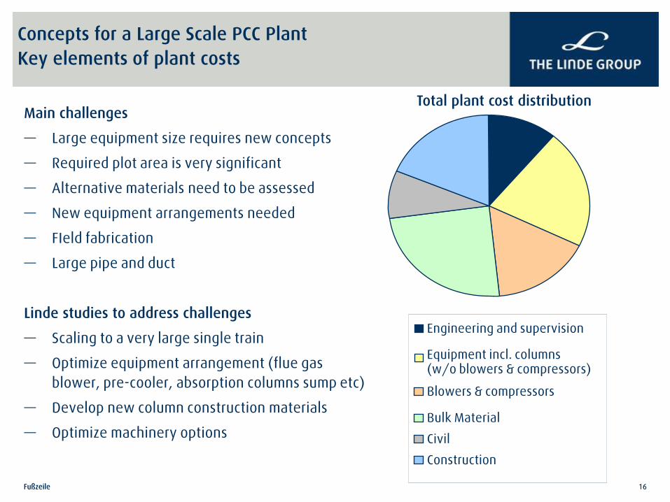
Concepts for a Large Scale PCC Plant Key elements of plant costs
Main challenges
— Large equipment size requires new concepts
— Required plot area is very significant
— Alternative materials need to be assessed
— New equipment arrangements needed
— FIeld fabrication
— Large pipe and duct
Linde studies to address challenges
— Scaling to a very large single train
— Optimize equipment arrangement (flue gas blower, pre-cooler, absorption columns sump etc)
— Develop new column construction materials
— Optimize machinery options
Total plant cost distribution
Engineering and supervision
Equipment incl. columns (w/o blowers & compressors)
Blowers & compressors
Bulk Material
Civil
Construction
Fußzeile 17
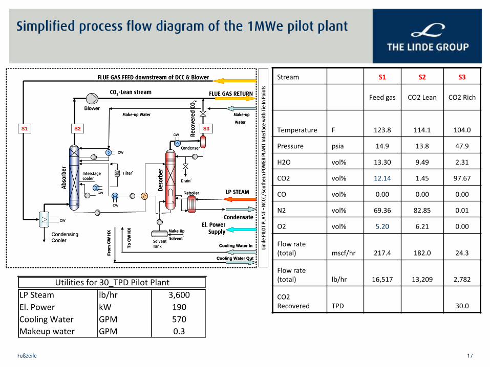
Simplified process flow diagram of the 1MWe pilot plant
Stream S1 S2 S3
Feed gas CO2 Lean CO2 Rich
Temperature F 123.8 114.1 104.0
Pressure psia 14.9 13.8 47.9
H2O vol% 13.30 9.49 2.31
CO2 vol% 12.14 1.45 97.67
CO vol% 0.00 0.00 0.00
N2 vol% 69.36 82.85 0.01
O2 vol% 5.20 6.21 0.00
Flow rate (total) mscf/hr 217.4 182.0 24.3
Flow rate (total) lb/hr 16,517 13,209 2,782
CO2 Recovered TPD 30.0
Reco
vere
d CO
2
Deso
rber
FLUE GAS FEED downstream of DCC & Blower
Abso
rber
Condenser
Filter*
Reboiler LP STEAM
CO2-Lean stream
Make-up Water
Interstagecooler
Solvent Tank
Make Up
Solvent*
Condensate
FLUE GAS RETURN
Make-up
Water
Cooling Water In
CW
CW
CW
CW
CW
To C
W H
X
From
CW
HX
Cooling Water OutLi
nde
PILO
T PL
ANT
–N
CCC/
Sout
hern
PO
WER
PLA
NT
Inte
rfac
e w
ith T
ie In
Poi
nts
El. Power Supply
Drain*
S1 S2 S3
Blower
Condensing Cooler
LP Steam lb/hr 3,600El. Power kW 190Cooling Water GPM 570Makeup water GPM 0.3
Utilities for 30_TPD Pilot Plant
Fußzeile 18 Fußzeile 18
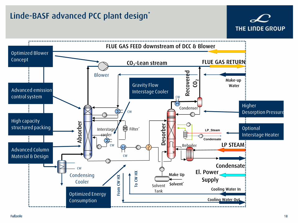
Linde-BASF advanced PCC plant design*
Reco
vere
d CO
2
Deso
rber
FLUE GAS FEED downstream of DCC & Blower
Abso
rber
Condenser
Filter*
Reboiler LP STEAM
CO2-Lean stream
Make-up Water
Interstage cooler
Solvent Tank
Make Up
Solvent*
Condensate
FLUE GAS RETURN
Make-up Water
Cooling Water In
CW
CW
CW
CW
CW
To C
W H
X
From
CW
HX
Cooling Water Out
El. Power Supply
S1
Blower
Condensing Cooler
Advanced emission control system
High capacity structured packing
Optimized Blower Concept
Optimized Energy Consumption
Higher Desorption Pressure
Optional Interstage Heater
Condensate
LP_Steam
Advanced Column Material & Design
Gravity Flow Interstage Cooler

Fußzeile 19
Techno-Economic Assessment: Linde-BASF PCC Plant Design for 550 MWe PC Power Plant
● Single train PCC design for ~ 13,000 TPD CO2 capture
● 40-50% reduced plot area to 180m x 120 m
Specifications and Design Basis
identical to DOE/NETL Report 2007/1281
as per DE-FOA-0000403 requirements
— Bituminous Illinois #6 Coal Characteristics
— Site Characteristics and Ambient Conditions
— Pulverized Coal Boiler Design
— Subcritical Steam Turbine Design
— Steam Cycle Conditions
— Environmental Controls and Performance
— Balance of Plant
— Economic Assumptions and Methodology
UniSim Design Suite R390, integrated with
— Brian Research & Engineering ProMax®
software for PCC parametric optimization
— BASF’s proprietary package for rigorous solvent performance predictions

Fußzeile 20
PCC – Power Plant Typical Process Integration Option (LB-1)
SECONDARY AIR FANS
COAL FEED
PULV
ERIZ
ED C
OAL
BOIL
ER
PRIMARY AIR FANS
INFILTRATION AIR
SCR
BOILER
FEEDWATER
HP ST
FEEDWATER HEATER SYSTEM
MAIN STEAM
COLD REHEAT
HOT REHEAT
IP ST LP ST
CONDENSER
CO2 CAPTURE & COMPRESSION PLANT
BAGHOUSE FGD
ID FANS
LIMESTONE SLURRY
CO2 COMPR.
TO STACK
MAKEUP WATER
OXIDATION AIR
GYPSUM
BOTTOM ASH
FLY ASH
CO2 PRODUCT
EL. POWER GENERATOR
10
8
7
5
2 1
4 3
6
9
14 13
15 12
16 11
23
25
24
26
19
18 17
21
20
22
Absorber
Treated flue gasto stack
CO2to Compression
Reboiler
Desorber
Condenser
Make-up water
SolventStorage
Tank
Interstage Cooler
Flue gas
DCC
NaOH Tank
Rich/LeanSolvent
Hex
Flue gas blower
Solvent Cooler
Interstage Heater
LP_Steam
Condensatereturn
LP/IP_Steam
Condensate return
Solvent Filter
Water Wash
Water Wash
Water Cooler
Cooler
Separator
Fußzeile 21
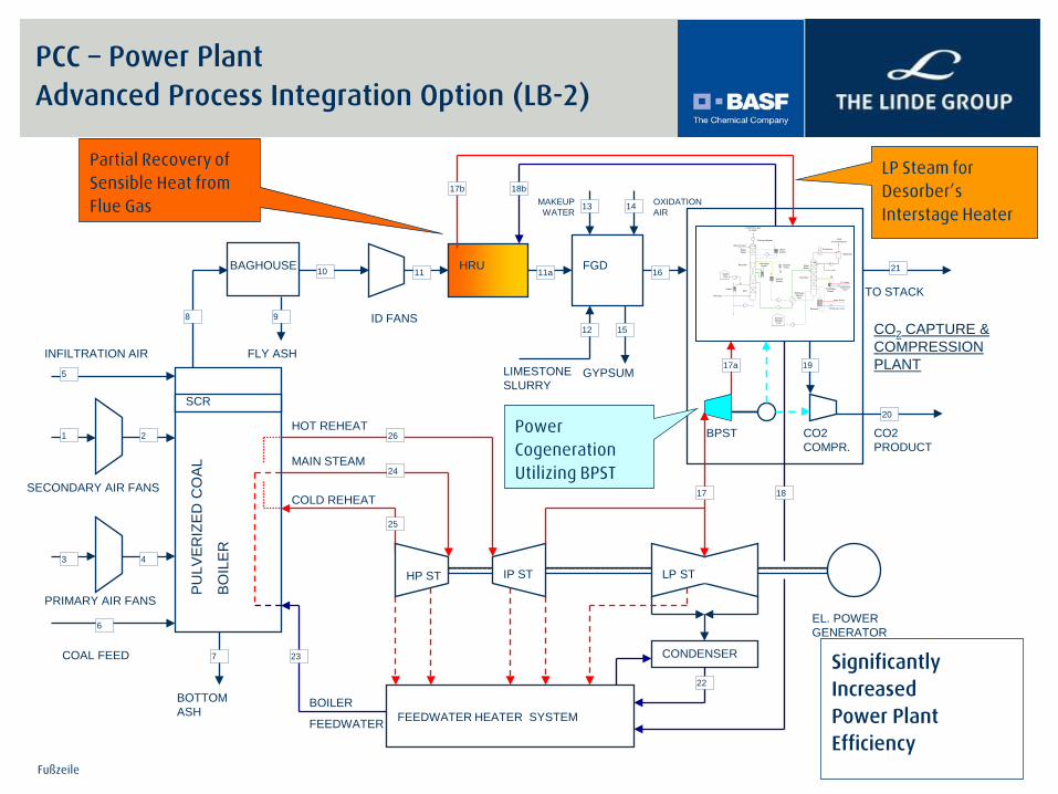
PCC – Power Plant Advanced Process Integration Option (LB-2)
SECONDARY AIR FANS
COAL FEED
PULV
ERIZ
ED C
OAL
BOIL
ER
PRIMARY AIR FANS
INFILTRATION AIR
SCR
BOILER
FEEDWATER
HP ST
FEEDWATER HEATER SYSTEM
MAIN STEAM
COLD REHEAT
HOT REHEAT
IP ST LP ST
CONDENSER
CO2 CAPTURE & COMPRESSION PLANT
BAGHOUSE FGD
ID FANS
LIMESTONE SLURRY
CO2 COMPR.
TO STACK
MAKEUP WATER
OXIDATION AIR
GYPSUM
BOTTOM ASH
FLY ASH
CO2 PRODUCT
EL. POWER GENERATOR
10
8
7
5
2 1
4 3
6
9
14 13
15 12
16 11 11a HRU
23
25
24
26
19
18b
18
17a
17
17b
21
20
BPST
Absorber
Treated flue gasto stack
CO2to Compression
Reboiler
Desorber
Condenser
Make-up water
SolventStorage
Tank
Interstage Cooler
Flue gas
DCC
NaOH Tank
Rich/LeanSolvent
Hex
Flue gas blower
Solvent Cooler
Interstage Heater
LP_Steam
Condensatereturn
LP/IP_Steam
Condensate return
Solvent Filter
Water Wash
Water Wash
Water Cooler
Cooler
Separator
22
Partial Recovery of Sensible Heat from Flue Gas
LP Steam for Desorber’s Interstage Heater
Power Cogeneration Utilizing BPST
Significantly Increased Power Plant Efficiency

Fußzeile 22
Energy demand for different PCC plants
0%
10%
20%
30%
40%
50%
60%
70%
80%
90%
100%
Reboiler Duty Cooling Duty Electrical Power
Spec
ific
ener
gy d
eman
d el
emen
ts
NETL-MEA Linde-BASF PCC (LB-1) Linde-BASF PCC (LB-2)
`
Effect of PCC technology improvementson incremental energy requirement for
power plant w ith CO2 capture and compression
0%
10%
20%
30%
40%
50%
60%
70%
80%
90%
100%
NETL-MEA Linde-BASF PCC(LB-1)
Linde-BASF PCC (LB-2)
Incr
emen
tal f
uel r
equi
rem
ent f
or C
O2
capt
ure
and
com
pres
sion
Comparative PCC Performance Results Linde-BASF vs Reference DOE/NETL Case*
* Reference Case # 10 of DOE-NETL 2007/1281 Report
Fußzeile 23
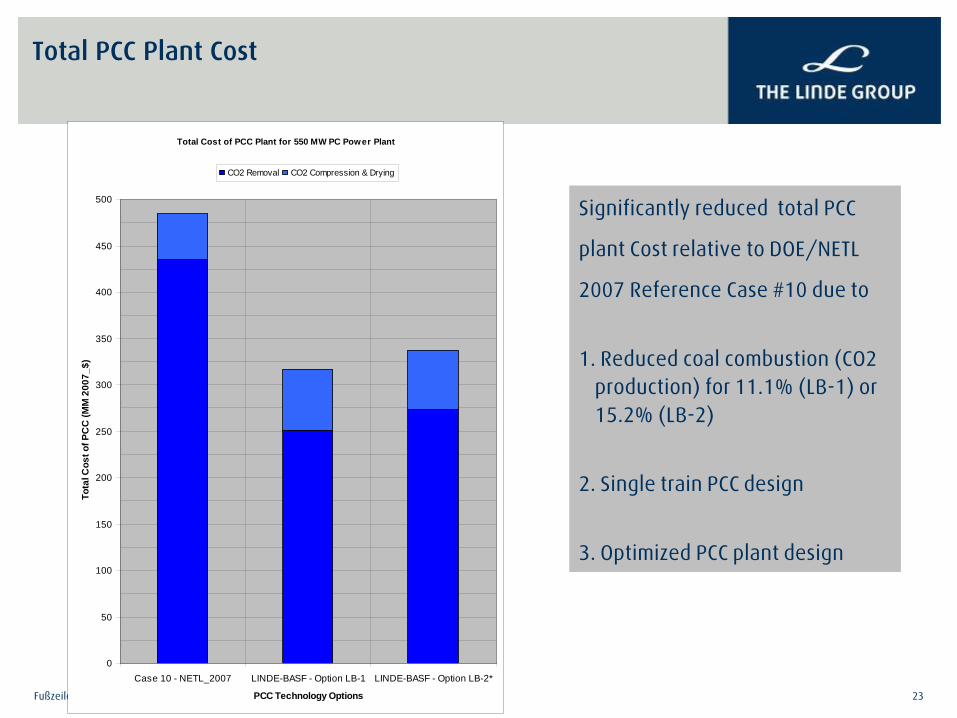
Total PCC Plant Cost
Total Cost of PCC Plant for 550 MW PC Power Plant
0
50
100
150
200
250
300
350
400
450
500
Case 10 - NETL_2007 LINDE-BASF - Option LB-1 LINDE-BASF - Option LB-2*
PCC Technology Options
Tota
l Cos
t of P
CC
(MM
200
7_$)
CO2 Removal CO2 Compression & Drying
Significantly reduced total PCC
plant Cost relative to DOE/NETL
2007 Reference Case #10 due to
1. Reduced coal combustion (CO2 production) for 11.1% (LB-1) or 15.2% (LB-2)
2. Single train PCC design
3. Optimized PCC plant design
Fußzeile 24
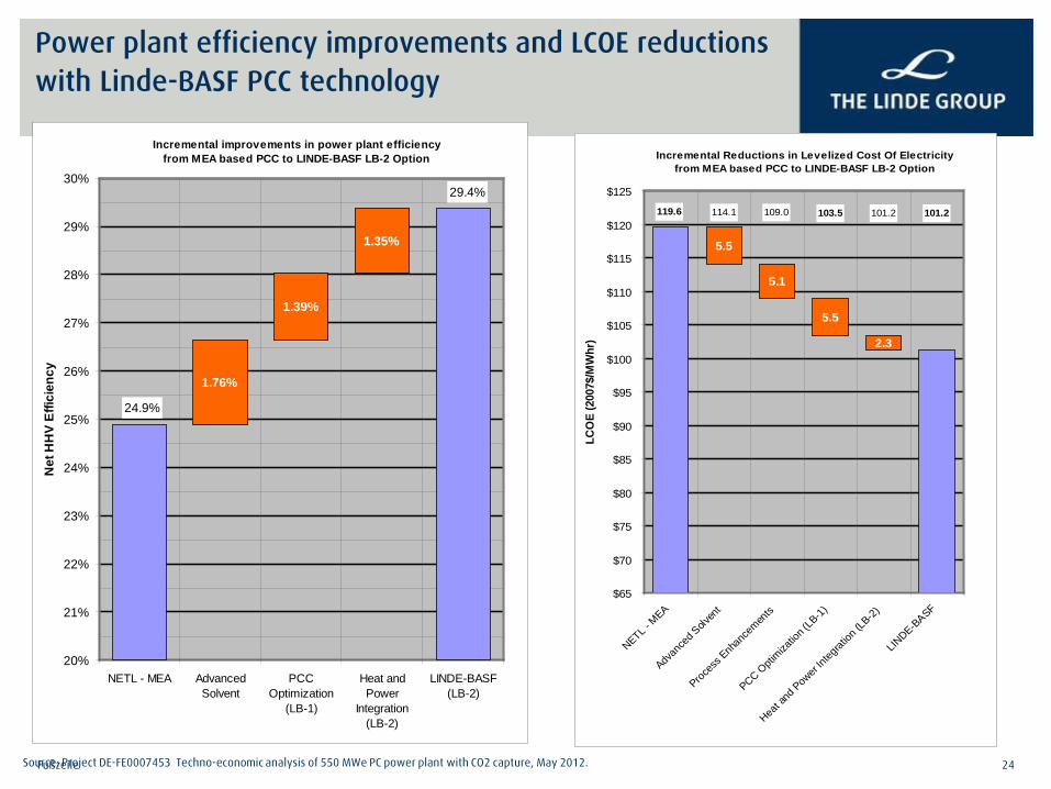
Power plant efficiency improvements and LCOE reductions with Linde-BASF PCC technology
Incremental improvements in power plant efficiencyfrom MEA based PCC to LINDE-BASF LB-2 Option
1.76%
1.35%
24.9%
29.4%
1.39%
20%
21%
22%
23%
24%
25%
26%
27%
28%
29%
30%
NETL - MEA AdvancedSolvent
PCCOptimization
(LB-1)
Heat andPower
Integration(LB-2)
LINDE-BASF(LB-2)
Net
HH
V Ef
ficie
ncy
Incremental Reductions in Levelized Cost Of Electricityfrom MEA based PCC to LINDE-BASF LB-2 Option
5.5
5.5
2.3
101.2101.2103.5109.0114.1119.6
5.1
$65
$70
$75
$80
$85
$90
$95
$100
$105
$110
$115
$120
$125
NETL - M
EA
Advan
ced S
olven
t
Proces
s Enh
ance
ments
PCC Opti
mizatio
n (LB
-1)
Heat a
nd Pow
er Int
egrat
ion (L
B-2)
LINDE-B
ASF
LCO
E (2
007$
/MW
hr)
Source: Project DE-FE0007453 Techno-economic analysis of 550 MWe PC power plant with CO2 capture, May 2012.

Fußzeile 25
Detailed engineering timeline: Key dates
Jan-12 Feb-12 Mar-12 Apr-12 May-12 Jun-12 Jul-12 Aug-12 Sep-12 Oct-12 Nov-12 Dec-12
- Design review- PSR 1 and 2- Hazop
- 60% model review- Evaluate optimum layout - Equipment packages
- Vendor selection- 3-D model - Cost compilation- 30% model review - 90% model review- Update P&ID (Hazop actions) - PSR 3
- Module package- RFQ to vendors
PSR: Process Safety review; P&ID: Process and Instrumentation Diagrams; RFQ: Request for quotes; Hazop: Hazard and operability study

Fußzeile 26
Task 3: Design Selection Pilot Plant Layout
Fußzeile 26
Optimized plant layout to be investigated
Fußzeile 27
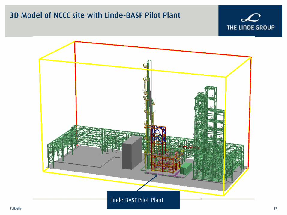
3D Model of NCCC site with Linde-BASF Pilot Plant
Linde-BASF Pilot Plant

Fußzeile 28
3D Model of Linde-BASF 1 MWe Pilot Plant
Absorber
Stripper
Structural support for windload protection
Fußzeile 29
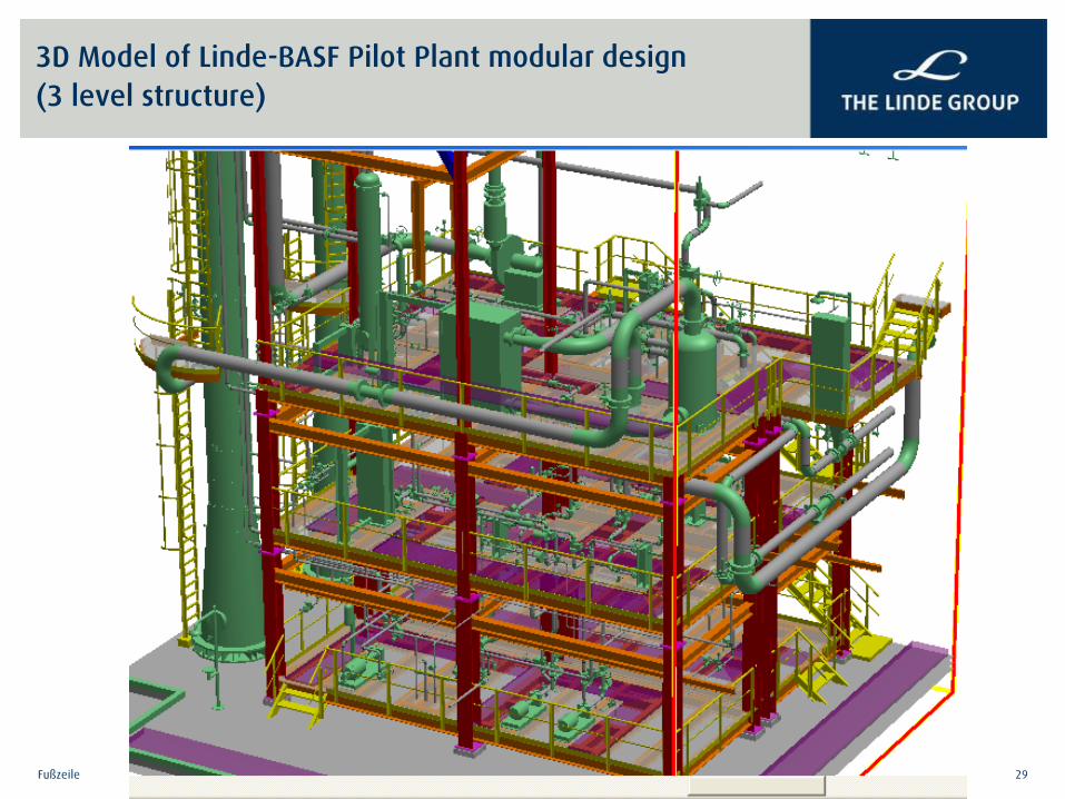
3D Model of Linde-BASF Pilot Plant modular design (3 level structure)

Fußzeile 30
Key design and engineering features and decisions
● Joint design basis development (Linde and SCS/NCCC) for the nominal 1 MWe pilot plant
● Leveraged Niederaussem pilot plant experience for early design selection decision on target solvent, pilot plant preliminary sizing, process control and analytical sampling and measurement
● Targeted 1 m absorber diameter size, leading to testing capability to 30 TPD CO2 or 1.5 MWe equivalent – confirmed utility availability with upside margins
● Integrated modeling approach for detailed engineering – start with the existing NCCC facility model with tie-in points defined and integrated into pilot plant model to avoid conflicts in build phase
● Equipment and module packages sent to multiple vendors and vendor selection performed based on cost, capability and eagerness for involvement in project
● Concrete column sections evaluated but determined to impact project timeline significantly – currently allowing for swapping the SS bottom section of absorber with concrete section.
● Concrete column section engineering design to be completed in BP2 and cost proposal made during the continuation request for BP3.
● Current pilot plant equipment procurement and build schedule (BP2) requires BP2 timeframe extension by 3-months. Will explore improving the schedule.

Fußzeile 31
Project progress: Key Project Milestones (Budget Period 1) Status
Budget Period 1 (Dec. 1, 2011 – Feb. 28, 2013)
— Submit project management plan (03/09/2012) √
— Conduct kick-off meeting with DOE-NETL (11/15/2011) √
— Complete initial techno-economic analysis on a 550 MWel power plant (05/04/2012) √
— Complete basic design and engineering of a 1 MWe pilot plant to be tested at NCCC (06/20/2012) √
— Execute host site agreement (10/31/2012) – completed 01/09/2013 √
— Complete initial EH&S assessment (10/31/2012) – Completed 12/14/2012 √
— Complete detailed pilot plant engineering and cost analyis for the 1 MWe pilot plant to be tested at NCCC (01/31/2013) Planned for completion by 01/31/2013

Fußzeile 32
Status against Budget Period 1 decision point success criteria
Decision Point Basis for Decision/Success Criteria Status
Completion of
Budget Period 1
Successful completion of all work proposed in Budget Period 1 On track
Demonstrate a 10% reduction in capital costs with Linde-BASF CO2 capture process
30.5 to 34.7% for PCC and 16.6 to 17.3% for integrated power plant
Demonstrate a LCOE increase of less than 65% over the baseline
62.2% and 58.8% for 2 options considered
Submission of an Executed Host Site Agreement Completed
Submission of a Topical Report – Initial Techno-Economic Analysis
Completed
Submission of a Topical Report – Initial EH&S Assessment Submitted
Submission of a Topical Report – Detailed Pilot Plant Engineering and Cost Analysis
By 1/31/2013
Submission and approval of a Continuation Application in accordance with the terms and conditions of the award
Presentation to DOE-NETL on Jan 14, 2013

Fußzeile 33
Acknowledgement and Disclaimer
Acknowledgement: This presentation is based on work supported by the Department of Energy under Award Number DE-FE0007453. Disclaimer: “This presentation was prepared as an account of work sponsored by an agency of the United States Government. Neither the United States Government nor any agency thereof, nor any of their employees, makes any warranty, express or implied, or assumes any legal liability or responsibility for the accuracy, completeness, or usefulness of any information, apparatus, product, or process disclosed, or represents that its use would not infringe privately owned rights. Reference herein to any specific commercial product, process, or service by trade name, trademark, manufacturer, or otherwise does not necessarily constitute or imply its endorsement, recommendation, or favoring by the United States Government or any agency thereof. The views and opinions of authors expressed herein do not necessarily state or reflect those of the United States Government or any agency thereof.”
04/02/2013 34
Linde Overview & Focus on CCUS Pathways
PCC Technology & Update on DOE Project
CCUS Activities & Focus Areas

Linde Focus Areas
04/02/2013 35
Industry & Government Collaboration Technology Development
Commercial Areas of Focus Project Activities
– Coal Utilization Research Council (CURC) – National Enhanced Oil Recovery Initiative
(NEORI)
– Pre-Combustion: Rectisol advancements, improved integration
– Post-Combustion: commercial-scale demo, 3rd gen technology
– Oxy-Fuel: Advanced HP oxy-fuel
– “Bankable” arrangements – Risk-sharing models
– Summit’s Texas Clean Energy Project (TCEP) – Odessa, TX
– UK DECC Projects: including oxy-fuel & pre-combustion
– Various EOR-driven opportunities in US and abroad including NG-based CCUS
Challenges – Carbon value, lack of planning certainty – Risk-sharing & value-sharing of emitter, capturer, user
Key Goal – Develop repeatable commercial-scale projects – Continue focus on technology advancement
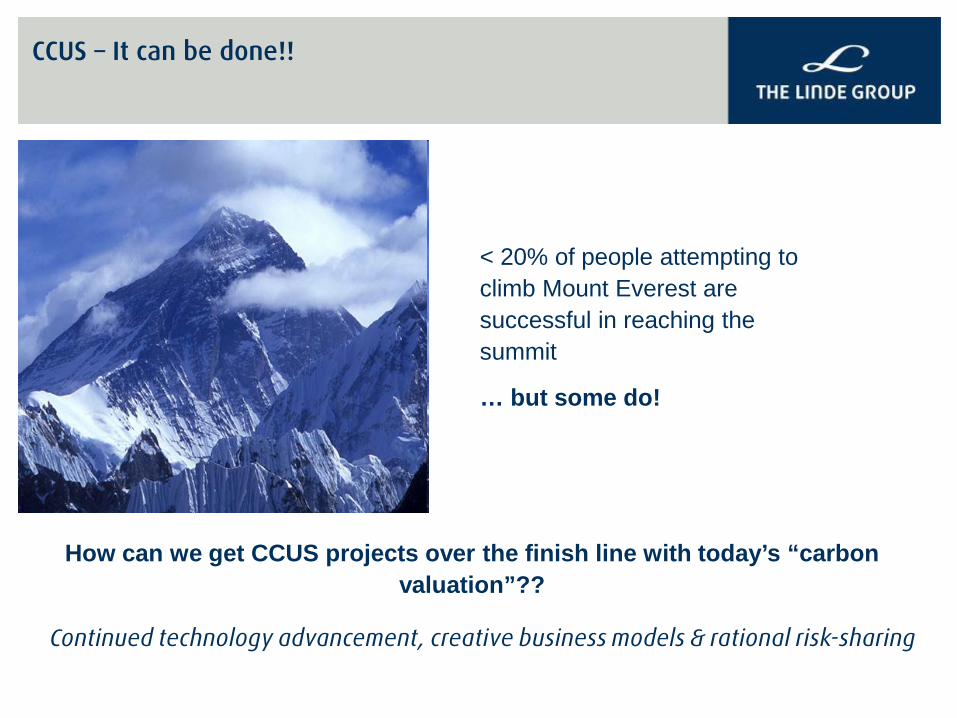
CCUS – It can be done!!
< 20% of people attempting to climb Mount Everest are successful in reaching the summit
… but some do!
How can we get CCUS projects over the finish line with today’s “carbon valuation”??
Continued technology advancement, creative business models & rational risk-sharing