line-of-sight obstruction analysis for vehicle-to-vehicle...
TRANSCRIPT

LUND UNIVERSITY
PO Box 117221 00 Lund+46 46-222 00 00
Line-of-Sight Obstruction Analysis for Vehicle-to-Vehicle Network Simulations in a TwoLane Highway Scenario
Abbas, Taimoor; Tufvesson, Fredrik
Published in:International Journal of Antennas and Propagation
DOI:10.1155/2013/459323
Published: 2013-01-01
Link to publication
Citation for published version (APA):Abbas, T., & Tufvesson, F. (2013). Line-of-Sight Obstruction Analysis for Vehicle-to-Vehicle Network Simulationsin a Two Lane Highway Scenario. International Journal of Antennas and Propagation, 2013, [459323]. DOI:10.1155/2013/459323
General rightsCopyright and moral rights for the publications made accessible in the public portal are retained by the authorsand/or other copyright owners and it is a condition of accessing publications that users recognise and abide by thelegal requirements associated with these rights.
• Users may download and print one copy of any publication from the public portal for the purpose of privatestudy or research. • You may not further distribute the material or use it for any profit-making activity or commercial gain • You may freely distribute the URL identifying the publication in the public portal

Take down policyIf you believe that this document breaches copyright please contact us providing details, and we will removeaccess to the work immediately and investigate your claim.
Download date: 06. Jul. 2018
1
Line-of-Sight Obstruction Analysis forVehicle-to-Vehicle Network Simulations in a
Two-Lane Highway ScenarioTaimoor Abbas, and Fredrik Tufvesson
Abstract—In vehicular ad-hoc networks (VANETs) the impactof vehicles as obstacles has largely been neglected in the past.Recent studies have reported that the vehicles that obstruct theline-of-sight (LOS) path may introduce 10 − 20dB additionalloss, and as a result reduce the communication range. Most ofthe traffic mobility models (TMMs) today do not treat othervehicles as obstacles and thus can not model the impact ofLOS obstruction in VANET simulations. In this paper the LOSobstruction caused by other vehicles is studied in a highwayscenario. First a car-following model is used to characterizethe motion of the vehicles driving in the same direction on atwo-lane highway. Vehicles are allowed to change lanes whennecessary. The position of each vehicle is updated by using thecar-following rules together with the lane-changing rules for theforward motion. Based on the simulated traffic a simple TMMis proposed for VANET simulations, which is capable to identifythe vehicles that are in the shadow region of other vehicles.The presented traffic mobility model together with the shadowfading path loss model can take in to account the impact ofLOS obstruction on the total received power in the multiple-lanehighway scenarios.
I. INTRODUCTION
Vehicle-to-vehicle (V2V) communication is an emergingtechnology that has been recognized as a key communicationparadigm for safety, and infotainment applications in future in-telligent transportation systems (ITS). In recent years extensiveresearch efforts have been made to design reliable and faulttolerant vehicular ad-hoc network (VANET) communicationprotocols. However, the propagation channel is one of thekey performance limiting factor which is not yet completelyunderstood [1]; several aspects such as the impact of an-tenna placement on vehicles [2] and line-of-sight obstructionby other vehicles on V2V communication has largely beenneglected in the past. In [3], [4], it is stated that a vehiclethat obstructs the LOS path between the transmitter (TX) andreceiver (RX) vehicle may introduce 10 dB additional loss inthe received power, and as a result cause 3 times reducedcommunication range. This additional power loss can increaseup to 20 dB if the obstructing vehicle is tall and close to theRX vehicle [5].
Several network simulators suitable for VANET simula-tions exist today, e.g., ns-2 [6], OMNet++ [7], ns-3 [8], and
This work was partially funded by the ELLIIT- Excellence Center atLinkoping-Lund In Information Technology and partially funded by HigherEducation Commission (HEC) of Pakistan.
T. Abbas, and F. Tufvesson are with the Department of Electricaland Information Technology, Lund University, Lund, Sweden (e-mail:[email protected]; [email protected]).
JiST/SWANS [9]. These simulators are different from eachother in terms of run-time performance and memory usage[10]. Most of these simulators do not consider the impactof neighboring vehicles on the packet reception probabilities.To evaluate this impact in these simulators, a traffic mobilitymodel (TMM) should be implemented having at least theability to identify and categorize the vehicles into the followinggroups:
• Line-of-sight (LOS) - when the TX vehicle has opticalline of sight from the RX vehicle;
• Obstructed-line-of-sight (OLOS) - when the optical LOSbetween the TX and RX is obstructed by another vehicle.
In the VANET simulators the role of the TMM is very vitalin order to perform a realistic system simulations. Today thereare a number of traffic models that can be used in the VANETsimulators. Some of them are very advanced but equally com-plex, e.g., SUMO (Simulation of Urban Mobility) [11], whichcan be implemented in any of the aforementioned VANETsimulators. However, using such an advanced mobility modelis not desired if the purpose of the VANET simulations is toperform a simple system analysis. Therefore, for basic packetlevel performance evaluations less detailed but realistic trafficflow models, e.g., the optimal velocity (OV) car-followingmodel without or with the lane-change capabilities, [12], [13]respectively, can be used in the VANET simulators.
In this paper a TMM is discussed that is capable to identifyvehicles being in LOS and OLOS. The TMM is implementedin MATLAB in which the car-following model, which is usedto formulate the forward motion of vehicles, is used. The car-following model is of low complexity but gives a realistictraffic flow. The interaction between the lanes is also taken intoaccount by allowing vehicles to perform lane changes whennecessary conditioned that the considered vehicles fulfill cer-tain lane change requirements. The model is used to identifythe vehicles being in LOS and OLOS from the TX at eachtime instant. Moreover, the instantaneous position, headwaydistance, state, distance traveled in each state, and number oftransitions from one state to another are logged to calculatethe probability of vehicles being in the LOS and OLOS stateswith respect to distance between them. The traffic simulationsare performed based on realistic parameters and the resultsare compared with the measurement results collected duringan independent measurement campaign (for details, see [3]).
The main contribution of this paper is a TMM that isstraight-forward to integrate with VANET simulators in order

2
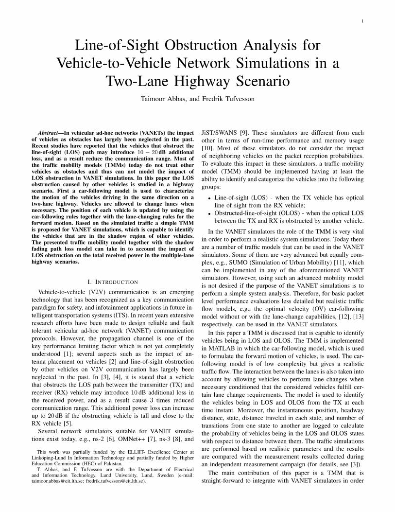
Lane 1
Lane 2
Fig. 1. The car-following traffic model for two-lane traffic. ∆x2,a(t), ∆x2,a−1(t), ∆xp2,a(t) and ∆xf
2,a(t) are the headway distances from the vehiclen2,a to the vehicles n2,a+1, n2,a−1, n1,a and n1,a−1, respectively. Where nl,a is vehicle label, l is lane number and a is lane specific vehicle index.
to study the impact of vehicles as obstruction. We do notderive the TMM itself, but we adapt models in the literatureto be used for VANET simulations. As mentioned above theTMM is capable to distinguish vehicles that are in LOS andOLOS states on a two-lane highway where the traffic flow isgenerated by using the lane-changing rules in the car-followingmodel. In addition to that, analytical expressions to find thepacket reception probability (PRP) are also provided. ThePRP can easily be estimated by utilizing the probability ofbeing in LOS or in OLOS calculated from the TMM intothe LOS/OLOS path-loss model proposed in [3]. Finally, thecorresponding results for PRP are calculated and comparedfor three different V2V channel models for highway scenario;1) the LOS only path-loss model by Karedal et al. [14], 2)the Nakagami-m based path-loss and fading model by Chenget al. [15], and 3) is the LOS/OLOS path-loss model in [3].
The remainder of the paper is organized as follows, theTMM including the car-following model and lane changerules are discussed in Section II. Section III explains themethod to distinguish between the LOS and OLOS situations.The simulation setup for the traffic mobility model, andprobabilities of vehicles being in LOS and OLOS states aregiven in Section IV. In Section V the analytical expressions forpacket reception probabilities are analyzed for completeness,while in Section VI conclusions are given.
II. TRAFFIC MOBILITY MODEL
In recent years, a number of research efforts have beenmade to understand and model complex traffic phenomena byusing the concepts from statistical physics [16]. Experimentalstudies have also been performed to analyze traffic and lanechange behaviors [17]. Among all these models, the car-following model is one of the most frequently used models todescribe vehicle motion. The car-following model is capableof describing real traffic as it takes into account the velocities,headway distances, relative speeds, and the attitude of thedrivers to model the traffic flow. The optimal velocity (OV)car following model, first introduced by Bando et al. [12],was extended for two-lanes in [13]. Tang et al. [18] furtherextended the model to incorporate the effect of potentiallane changing and analyzed the traffic flow stability. Thecar following model for two-lane traffic flow is discussedunderneath, in which the lane changing is also allowed. The
model is modified such that the probabilities of vehicles beingin LOS and OLOS situations can be obtained using simplegeometric manipulations that can further be integrated intothe VANET simulators.
A. The car-following model
Consider a highway with two lane traffic in each directionof travel and assume that the vehicles in each lane movealong a straight line. Let l = {1, 2} be the lane index forthe outer (fast) and inner (slow) lane, respectively. Vehicles inlane l are labeled as (..., nl,a−1, nl,a, nl,a+1, ...), where a isa lane specific vehicle index, their instantaneous positions are(..., xl,a−1(t), xl,a(t), xl,a+1(t), ...) and the headway betweenany two vehicles moving in the same lane are labeled as(...,∆xl,a−1(t),∆xl,a(t),∆xl,a+1(t), ...) at time instant t, asdescribed in Fig. 1. At each time instant t each of the two laneswill be classified as subject-lane or target-lane with respectto each subject vehicle. A subject-lane is the lane where thevehicle nl,a drives, and target-lane is the lane on which thevehicle nl,a intend to drive after the possible lane change.
A microscopic simulation model, the car-following model,is used to describe the movement of vehicles on the samelane. It explains a one-by-one following process of vehiclesand incarnate human behaviors which in turn reflects realistictraffic conditions. It has been shown that the car-followingmodel is a better way to model traffic-flow compared to theother common traffic-flow models [19]. Tang et al. [13], [18]developed a car-following model for two-lane traffic-flow inthe forward direction, expressed as follows:
d2xl,a(t)
dt2= αl
(Vl
(∆xl,a(t),∆xpl,a(t)
)− dxl,a(t)
dt
)+κl∆vl,a(t), (1)
where ∆vl,a(t) is the relative velocity between two vehiclesnl,a and nl,a+1, ∆xpl,a(t) is the distance between the vehiclenl,a and the preceding vehicle in the target lane, αl is thedriver’s sensitivity coefficient, and kl = λl
τlis the sensitivity
coefficient due to difference in velocity, in the lane l at timeinstant t, respectively. The delay τl is the time delay inwhich a vehicle attains its optimal velocity and λl ∈ (0, 1)is the sensitivity factor for the relative velocities which isindependent of time, position and velocity. However, it is

3
TX OLOSOLOS
Fig. 2. Identification of vehicles being in LOS and in OLOS of the TX vehicle; vehicles in the shaded-area are considered to be in OLOS where as all othervehicles have LOS from the TX.
assumed that the driving condition is better in the outer (fast)lane 1 compared to the inner (slow) lane 2, and thus λ1 > λ2.
The continuous model in (1) can be discretized usingforward difference to find the position of vehicle nl at anytime t+ 2τl [18] as given below,
xl,a(t+ 2τl) = xl,a(t+ τl) + τlVl (∆xl,a(t)) +
λlτl (xl,a(t+ τl)− xl,a(t)) . (2)
The above equation can also be written in terms of headwaysas,
∆xl,a(t+ 2τl) = ∆xl,a(t+ τl)
+τlVl (∆xl,a+1(t))− Vl (∆xl,a(t))
+λlτl (xl,a+1(t+ τl)− xl,a+1(t))
− (xl,a(t+ τl)− xl,a(t)) , (3)
where Vl (∆xl,a(t)) is the headway induced optimal velocityfunction (OVF). The OVF is given as follows,
Vl (∆xl,a(t)) = Vl
(∆xl,a(t),∆xpl,a(t)
)=
1
2vl,max (tanh(xl,a(t)− dpl ) + tanh(dpl )) , (4)
where dpl and vl,max are the minimum safety distance from thepreceding vehicle in the target lane and the maximum velocityin the lane l, respectively. Finally the weighted headwaysxl,a(t) are defined as,
xl,a(t) = β1∆xl,a + β2∆xpl,a(t), (5)
where β1 and β2 are the weights for the headways fromthe preceding vehicles in same lane and the target lane,respectively, and β1 > β2 given that β1 + β2 = 1. Thecar following model explained above is used to formulate theforward motion of vehicles.
The forward difference equations, (2) and (3), used to findthe positions and headways of the vehicles, respectively, dotake the driver sensitivity coefficients and sensitivity factorfor the relative velocity into account. However, many otherfactors (e.g., weather condition, road bumps, and driver mood)can also influence the traffic flow. Moreover, the vehicles areassumed to be moving along a straight line, which means novariations along the vertical axis and is not the case in reality.To summarize, we can say that the generated traffic flow isrealistic but due to simplifications it is noise free in the sense
that the vehicles follow the center point of the lanes. Hence, itis important to introduce some randomness to make the resultof the TMM more realistic, which is done in section V whenthe TMM is integrated with the LOS/OLOS path-loss model.
B. Lane change rules
To characterize realistic traffic in a multi-lane highwayscenario it is important to consider interaction between lanesand the lane change activities as it affects stability of the trafficflow. In [18] it is concluded that if lane changes are not allowedthen the system has a stable flow, but when the vehicles areallowed to change lanes then the system flow can becomemetastable or unstable depending upon the frequency of lanechange activities.
In our simulator each vehicle is allowed to perform lanechanges when necessary, conditioned that the vehicle fulfillsall lane change requirements. During a lane change eventboth the lanes are categorized either as the subject-lane or thetarget-lane. Whenever a vehicle changes lane from the subjectto target lane it becomes a vehicle in the target lane, and thusthe position, number and identity of each vehicle in both lanesare updated accordingly. It is assumed that the lane changeprocess is instantaneous, so when a vehicle changes lane itslongitudinal location remains the same as it was prior to thelane change.
In [18], [20], [21] several lane changing rules are definedthat can either be used independently or all together to modelthe lane change behavior. The lane-changing rule based onthe incentive and safety criterion defined in [18] states thatthe vehicle is allowed to change lane only if it fulfills thefollowing three criteria,
• The distance of the vehicle nl,a from the precedingvehicle nl,a+1 should be smaller than twice the safetydistance dpl , i.e.,
∆xl,a(t) < 2dpl . (6)
• The distance of the vehicle nl,a from the precedingvehicle in the target lane should be greater than thedistance of the vehicle nl,a from the preceding vehiclenl,a+1 in the same lane, i.e.,
∆xpl,a(t) > ∆xl,a(t). (7)
• Finally the distance ∆xl,a of the vehicle nl,a from thevehicle in the target lane following this vehicle nl,a

4
should be greater than the corresponding safety distanceof the following vehicles dfl , i.e.,
∆xfl,a(t) > dfl (8)
In [22] it is stated that 0.9 s is the minimum legal time-gapduring following, which gives the safety distance relative tothe velocity of the vehicle. Their measurement results showthat the time-gap during following is not fixed but it is relativeto the speed of the vehicle and traffic density. Thus, we cansay that the safety distance dpl and the corresponding safetydistance of the following vehicles dfl are random parameterswhich depend on the velocity of the subject vehicle given aminimum time-gap. In general the so-called two-second ruleis a rule of thumb to determine the correct following distance,i.e., a driver should ideally keep at least two seconds of time-gap from any vehicle that is in front of the subject vehicle.
III. LINE-OF-SIGHT OBSTRUCTION ANALYSIS
As mentioned above, to date most of the VANET simulatorsdo not consider the impact of line-of-sight obstruction, causedby neighboring vehicles, on the packet reception probabilities.To evaluate this impact in the simulator the TMM is requiredto identify and label each vehicle as in LOS or in OLOSsituation with respect to TX and RX at each instant t. Theidentification of vehicles being in LOS or in OLOS statesbecomes fairly simple as the TMM discussed earlier providesthe instantaneous position of each vehicle on the road. Thus,the position information of each vehicle together with somegeometric manipulations give the state information of eachvehicle being in LOS or in OLOS state as follows,
• Model each vehicle as a screen or a strip with theassumption that each vehicle has the same size.
• Assumed that the intended communication range is acircle of a certain radius, i.e., Rc. At each instant t thevehicles that are in this circle are considered only.
• Vehicles in each lane are assumed to be moving alonga straight line. Thus only two vehicles in the same, oneat the front and one in the back of the TX, will be inthe LOS. The rest of the vehicles in the same lane areconsidered to be in the OLOS state.
• Draw straight lines starting from the antenna position ofthe TX vehicle touching the edges of the vehicles in thefront and back to the edges of road (see Fig. 2). Allvehicles that are bounded by these lines are shadowed byother vehicles thus in the OLOS state.
• Vehicles that are not bounded by these lines are analyzedindividually to see if they are in LOS or in OLOS fromthe TX.
• The identification process is repeated for each vehicle andat each time instant t to find out whether the vehicles arein LOS and in OLOS states with respect to every othervehicle. The state information of each vehicle can thenbe used either for analytical performance evaluations orfor packet level VANET simulations.
IV. SIMULATIONS AND RESULTS
The TMM derived above is implemented in Matlab andsimulations are carried out in order to analyze the movement
0 50 100 150 200 2500
0.2
0.4
0.6
0.8
1
Headway distance [m]
CD
F
Vehicle 60Vehicle 120Vehicle 180
Fig. 3. CDFs of the headway distances of vehicles at every second for totalsimulation time T = 120 min.
of vehicles over time, their lane changing behavior and theintensities by which the vehicles change states from LOS-to-OLOS and from OLOS-to-LOS states, respectively. Thesimulations are performed on a two-lane 14.4 km long circularhighway. The circular highway refers to the fact that anyvehicle that departs from one end of the highway, i.e., beyond14.4 km, enters from the other end so that the traffic can flowfor infinite amount of time. The simulation parameters arechosen as follows.
For the simulations, the initial positions xl,a(0) and theheadways ∆xl,a(0) of all the vehicles nl,a in lane l for(a = 1, 2, ..., Nl) are determined by the rules given in [18]for both the lanes, l = {1, 2}. Initially it is assumed that thevehicles are distributed uniformly along each lane with therealistic flow rate given in the Highway Capacity Manual [23],i.e., 1300 vehicles/hour/lane and 1600 vehicles/hour/lane at anaverage speed of 30.5 m/s (110 km/h) and 22.5 m/s (80 km/h)in the outer-lane l = 1 and inner-lane l = 2, which implies1 vehicle per 3 s and 1 vehicle per 2.5 s, respectively.
The initial values of ∆xpl,a(0) and ∆xfl,a(0) are determinedfrom the initial positions xl,a(0) of the vehicles. The positionand headways at each instant are updated by (2) and (3).
Let N1 = 160 and N2 = 200 be the initial number ofvehicles in each lane, v1 = 27.7 m/s (100 km/h) and v2 =19.44 m/s (70 km/h) be the average velocity, and v1,max =30.5 m/s (110 km/h) and v2,max = 22.2 m/s (80 km/h) be themaximum speed in the outer and inner lanes, respectively. Theother parameters such as the delay time, sensitivity factors,and initial safety distances are τ1 = τ2 = 0.5 s, λ1 = 0.3and λ2 = 0.2, and df1 = dp1 = 40.5 and df2 = dp2 = 36 m,respectively.
Practically, the driver’s sensitivity α1 is larger than α2
because the driver’s response in the outer (fast) lane is moresensitive than in the inner (slow) lane. Here we assume thatα1 = α2 because for the simulations it is easy to computeheadways at fixed intervals and it is anticipated in [18] thatthe effect of αl is small and does not change final results.
We let the simulations run for 10800 simulation time stepsor seconds that correspond to 3 hours of simulated time. Thedata obtained from the first 3600 s of simulation is not con-sidered for analysis to ensure that steady-state conditions areobtained. Hence, the time 0 s in the final results correspondsto the time 3600 s of the simulation.

5
35 40 45 50
2
1
La
ne
Time [min]
Vehicle 60
35 40 45 50
2
1
La
ne
Time [min]
Vehicle 120
35 40 45 50
2
1
La
ne
Time [min]
Vehicle 180
Fig. 4. Three vehicles numbered 60, 120 and 180 changing lanes from lane1 to lane 2 or vice-versa between a time window of 35 min to 50 min.
Once the traffic flow is stable the positions and headwaysof all the vehicles are logged for each time instant, for furtheranalysis, with respect to the vehicles’ identity. The vehicles areallowed to change lane so whenever a vehicle changes lane itexits from subject lane and becomes part of the target lane.Thus for every lane change event at each time instant t theposition, and headway distances of each vehicle in both lanes,the subject and target lanes, should be updated accordingly.
The headways for three vehicles numbered 60, 120 and 180are shown as cumulative distribution function (CDF) in Fig. 3.It can be seen that there is a huge variation in the headwaydistances and they may vary between 20 m up to 600 m.
Further, to record the lane change activities, the total numberof lane changes, the position and time at which lane changeoccurred were logged over the simulation time for eachvehicle. A sample result is shown in Fig. 4 where the lanechange activities of the three vehicles numbered 60, 120 and180 are shown over 15 min of time window. It can be seenthat the lane change behavior for each vehicle is different atdifferent times. The amount of time a vehicle stays in eachlane depends very much on the driving conditions in that laneduring that particular time window.
As the main focus of this work is to identify the vehicleswhich are in OLOS from each other so that this informationcan be used for VANET simulations using the shadow fadingpath loss model given in [3]. In order to analyze the LOS andOLOS situation and to find the intensities by which vehiclesgo from one state to another the following assumptions aremade:
A vehicle numbered 20 is assumed to be the TX vehiclewhich is broadcasting the information with in the intendedcommunication range Rc where Rc is a circle of radius 500 mwith TX at its center. At each instant t the vehicles which liein the Rc of the TX vehicle are identified and then categorizedas vehicles being in LOS or in OLOS from the TX vehicle
0 5 10 15 20 25 30 35 400
0.2
0.4
0.6
0.8
1
Number of vehciles
CD
F
In Rc
In LOS
In OLOS
Fig. 5. CDFs of the total number of vehicles in Rc and, the number ofvehicles in LOS and OLOS state at each time instant for total simulationtime T = 120 min.
0 1 2 3 4 5 60
0.2
0.4
0.6
0.8
1
Distance interval [km]
CD
F
In LOS
In OLOS
(a)
0 10 20 30 40 50 60 700
0.2
0.4
0.6
0.8
1
Total distance traveled by each vehicle [km]
CD
F
In LOS
In OLOS
(b)
Fig. 6. CDFs of; (a) the LOS and OLOS intervals for all vehicles, and (b)the total distance traveled in the LOS and OLOS by all vehicles.
using the rules defined in section III. Any other vehicle that isoutside this intended communication range Rc is treated as avehicle out-of-range (OoR) from the TX. The states of vehiclesbeing in LOS, OLOS and OoR w.r.t. their identities are savedfor each time instant. The CDF of the total number of vehiclesin Rc and, the number of vehicles in LOS and OLOS state ateach time instant are shown in Fig. 5, respectively. The OoRstate is not interesting thus it is not discussed further.
Each time a vehicle is in LOS, or in OLOS, it remains inthat state for a certain amount of time and travels a distance,dLOSl,a (k) or dOLOSnl,a
(k), where k ∈ {1,K} is the index ofthat specific interval. The length of these intervals may varyover time as well as for each vehicle. So we log the count ofthese intervals and their corresponding distances dLOSl,a (k) anddOLOSnl,a
(k) for every vehicle over the whole simulation time.

6
0 0.01 0.02 0.03 0.04 0.050
0.2
0.4
0.6
0.8
1
State transsition intensities
CD
F
LOS−OLOS
OLOS−LOS
Fig. 7. CDFs of the state transition intensities P and p from LOS-OLOSand OLOS-LOS, for each vehicle, respectively.
0 200 400 600 800 10000
0.5
1
Distance between TX and RX [m]
Pro
ba
bili
ty
LOS receptions
OLOS receptions
Fig. 8. The probability of LOS and OLOS with respect to distance, it can beseen that the probability of being in LOS decreases as the distance increases.
The CDFs of LOS and OLOS distance intervals for all vehiclesare shown in Fig. 6(a). We log the total distance traveled byeach vehicle, Dl,a, during the simulation time and see howmuch of that distance is traveled in the LOS and OLOS state,DLOSl,a and DOLOS
l,a , by the vehicle nl,a. The CDFs of totaldistance traveled in the LOS and OLOS by all vehicles areshown in Fig. 6(b).
The number of state transitions, NLOS−OLOSl,a and
NOLOS−LOSl,a , from LOS-OLOS and OLOS-LOS states are
counted for each vehicle. Thus the state transition intensitiesP and p from LOS-OLOS and OLOS-LOS for each vehiclecan be calculate as,
P =NLOS−OLOSl,a
DLOSl,a
, (9)
p =NOLOS−LOSl,a
DOLOSl,a
. (10)
The CDF of the state transition intensities P and p for agiven set of parameters are shown in Fig. 7. The variations inthe transition intensities are due to the fact that each vehiclehas different moving and lane-changing pattern. The meanintensities µP and µp are calculated to be 0.0034m−1 and0.0026m−1, respectively. For comparison, sample state tran-sition intensities are also calculated from the measurement datacollected during a V2V measurement campaign conductedin the city of Lund and Malmo, Sweden, to analyze theshadow fading effects. The measurement data was separatedfor LOS and OLOS conditions (explained briefly in [3]).The separated data contains information about the numberof state transitions between LOS and OLOS states, and the
distance traveled in each state. With this information the statetransition intensities are calculated using (9) and (10), i.e.,Pmeasured = 0.0035m−1 and pmeasured = 0.0020m−1,which are close to the mean values of the simulated intensities.The probability of vehicles being in LOS and in OLOSwith respect to the distance can also be calculated from thesimulation, as shown in Fig. 8.
V. ANALYTICAL PERFORMANCE EVALUATION
In order to evaluate the impact of vehicle as an obstructionon V2V networks the proposed TMM together with theLOS/OLOS path-loss model given in [3] can be used in anyVANET simulator. The LOS/OLOS path-loss model providesthe deterministic and stochastic parameters of a dual slopedistance dependent path-loss for both the LOS and OLOSsituations. The stochastic part of the LOS/OLOS path-lossmodel comes from the large-scale fading, which is assumedto be Gaussian distributed. The packet reception probability(PRP) can be obtained by analytical expressions for all vehi-cles either in LOS or in OLOS states. Large-scale fading, orshadow fading, may refer to the signal variations that may notonly be associated to blocked LOS but due to the blocking ofmany other significant reflected propagation paths. Therefore,it is associated to both the LOS and the OLOS state. The large-scale fading is a random process and it varies over time dueto varying locations when the TX/RX vehicles are moving.The proposed TMM is assumed to be noise free, therefore therequired noise due to randomness in driving behavior can betaken into account by large-scale fading process, which has astandard deviation σ, that introduces variation in the receivedpower due to variation in the position of each vehicle at eachinstant.
To study the performance differences in the PRP withand without considering vehicles as obstacles the LOS/OLOSmodel is compared with two other aforementioned path-lossmodels; 1) the LOS only single slope path-loss model byKaredal et al. [14], 2) the Nakagami-m based path-loss andfading model by Cheng et al. [15] in which the data fromLOS and blocked LOS cases is lumped together for modelingpurpose.
To find an analytical expression for packet reception prob-ability, it is assumed that each vehicle is a point source andvehicles are distributed along a straight line on both lanes ofthe highway and the probability of LOS and OLOS is known.The parameters of Karedal’s LOS model, Cheng’s Nakagamibased model, and LOS/OLOS model are taken from [14],[15], and [3], respectively. Then the received power PwRXfor LOS-Karedal, LOS-Dual slope, OLOS-Dual slope, Chengmodel, and joint LOS/OLOS (LOS/OLOS model together withprobability of LOS and OLOS) cases can individually becalculated as follows,
PwRX(d) = PwTX − PL(d), (11)
where PL(d) is a distance dependent mean power loss, givenas,

7
PL(d) =
PL0 + 10n1 log10
(dd0
)+Xσ, if d0 ≤ d ≤ db
PL0 + 10n1 log10
(dbd0
)+ if d > db
10n2 log10
(ddb
)+Xσ,
(12)where Xσ describes the large scale fading as zero meanGaussian distributed random variable with standard deviationσ, PL0 is the received power level at a reference distanced0 = 10 m and, n1 and n2 are the path-loss exponents,respectively. The value of PL0, n1, n2 and σ for each of theabove mentioned models are different and are obtained fromthe models given in [3], [14], [15]. The received power forall five cases is shown in Fig. 9 for a transmitted powerPwTX = 20 dBm. For the dual-slope LOS/OLOS modeland Cheng’s model the break point distance is provided, i.e.,db = 104 m, however for Karedal’s single slope LOS modeldb is not required and thus it can assumed to be infinity.
From the above equations it is obvious that the receivedpower is a Normally distributed with a distance dependentmean µ(d) = PwTX − PL(d) and standard deviation σ. TheGaussian probability density function is closely related to Q-function [24], therefore, for a given distance d the probabilityof received power being greater than α, P{PwRX(d) > α},is calculated analytically as follows,
P{PwRX(d) > α} = 1−Q(µ(d)− α
σ
), (13)
where α is carrier sense threshold (CSTH). The parameters foreach of these models can be used individually to find the prob-abilities PKaredal{PwRX(d) > α}, PCheng{PwRX(d) >α}, PLOS{PwRX(d) > α} and POLOS{PwRX(d) > α},respectively.
The probability of successful packet reception is shown inFig. 10, where CSTH= −91 dBm is assumed [25]. How-ever the joint LOS/OLOS PRP is calculated by multiplyingthe probability of LOS and OLOS to the individual PRP,PLOS{PwRX(d) > α} and POLOS{PwRX(d) > α}, ofLOS and OLOS as follows,
PRPLOS/OLOS = PrLOS × PLOS{PwRX(d) > α}+
PrOLOS × POLOS{PwRX(d) > α}. (14)
From the Fig. 9 and Fig. 10, it can obviously be seen thatthe LOS and OLOS situations are fundamentally different.Comparing the PRP curves from the Karedal, Cheng andLOS/OLOS model, it can be observed that for the given ve-hicular traffic density the probabilities of LOS and OLOS varywhich in turn affect the performance of the joint LOS/OLOSPRP. However, Karedal’s path-loss model and Cheng’s modeldo not take probabilities of LOS and OLOS into account andthus can not capture the effects of traffic density on the PRP.All models perform similar up to d = 100 m approximately.However at the larger distances, where the probability of LOSobstruction increases, the behavior of these models differ.
101
102
103
−120
−110
−100
−90
−80
−70
−60
−50
−40
Distance between TX and RX [m]
Re
ce
ive
d P
ow
er
[dB
m]
LOS−KaredalLOS−Dual slopeOLOS−Dual slopeCheng modelLOS/OLOS joint
Fig. 9. Received power as a function of distance. Breakpoint distance ofdb = 104 m is used for the LOS-Dual slope, OLOS-Dual slope, Cheng andjoint LOS/OLOS models.
101
102
103
0
0.2
0.4
0.6
0.8
1
Distance between TX and RX [m]
Pa
cke
t R
ece
ptio
n P
rob
ab
ility
LOS−KaredalLOS−Dual slopeOLOS−Dual slopeCheng modelLOS/OLOS joint
Fig. 10. The probability of successful packet reception for a CSTH of−91 dBm.
VI. SUMMARY AND CONCLUSIONS
In this paper the effect of line-of-sight (LOS) obstructionis analyzed for vehicle-to-vehicle (V2V) network simulationsin a two-lane highway scenario using a traffic mobility model(TMM). A microscopic simulation model, the car-followingmodel, is used to describe the movement of vehicles in theforward direction and the vehicles are allowed to changelane when necessary. Realistic parameters are used for thesimulations to achieve a traffic flow being as realistic aspossible. Based on the simulated traffic the positions of allvehicles at each instant are recorded. The position informationis then used to identify vehicles which are in LOS, obstructed-LOS (OLOS) or out-of-range (OoR) from a selected vehiclethat is assumed to be a transmitter in the case of VANETsimulations. Vehicles at each instant are defined either in oneof the LOS, OLOS or OoR states. The intensities of vehiclesbeing in each states are logged which can be used to takeinto account the impact of OLOS in the VANET simulations.The proposed model is straight-forward to implement, givesrealistic results and is based on realistic assumptions for thetraffic mobility. Analytical expressions for the packet receptionprobabilities are used together with the models. The resultsshow the importance of including shadowing by other vehicles

8
for realistic performance assessment.
REFERENCES
[1] J. Gozalvez, M. Sepulcre, and R. Bauza, “Impact of the radio channelmodeling on the performance of VANET communication protocols,”Telecommunication Systems, pp. 1–19, Dec. 2010.
[2] T. Abbas, J. Karedal, and F. Tufvesson, “Measurement-based analysis:The effect of complementary antennas and diversity on vehicle-to-vehicle communication,” IEEE Antennas and Wireless PropagationLetters, vol. 12, no. 1, pp. 309–312, 2013. [Online]. Available: http://lup.lub.lu.se/record/3516482/file/3555826.pdf
[3] T. Abbas, F. Tufvesson, and J. Karedal, “Measurement based shadowfading model for vehicle-to-vehicle network simulations,” ArXiv e-prints,Mar. 2012.
[4] M. Boban, T. Vinhoza, M. Ferreira, J. Barros, and O. Tonguz, “Impactof vehicles as obstacles in vehicular ad hoc networks,” Selected Areasin Communications, IEEE Journal on, vol. 29, no. 1, pp. 15–28, Jan.2011.
[5] R. Meireles, M. Boban, P. Steenkiste, O. Tonguz, and J. Barros, “Ex-perimental study on the impact of vehicular obstructions in VANETs,”in 2010 IEEE Vehicular Networking Conference (VNC), dec. 2010, pp.338–345.
[6] The network simulator - ns-2. [Online]. Available: http://www.isi.edu/nsnam/ns/
[7] A. Varga and R. Hornig, “An overview of the omnet++ simulationenvironment,” in Proceedings of the 1st international conference onSimulation tools and techniques for communications, networks andsystems & workshops, ser. Simutools ’08. ICST, Brussels, Belgium,Belgium: ICST (Institute for Computer Sciences, Social-Informaticsand Telecommunications Engineering), 2008, pp. 60:1–60:10. [Online].Available: http://dl.acm.org/citation.cfm?id=1416222.1416290
[8] T. R. Henderson, S. Roy, S. Floyd, and G. F. Riley, “ns-3 projectgoals,” in Proceeding from the 2006 workshop on ns-2: the IP networksimulator, ser. WNS2 ’06. New York, NY, USA: ACM, 2006. [Online].Available: http://doi.acm.org/10.1145/1190455.1190468
[9] R. Barr, Z. J. Haas, and R. van Renesse, “Jist: an efficient approachto simulation using virtual machines: Research articles,” Softw. Pract.Exper., vol. 35, no. 6, pp. 539–576, May 2005. [Online]. Available:http://dx.doi.org/10.1002/spe.v35:6
[10] E. Weingartner, H. vom Lehn, and K. Wehrle, “A performance compar-ison of recent network simulators,” in Communications, 2009. ICC ’09.IEEE International Conference on, 2009, pp. 1–5.
[11] M. Behrisch, L. Bieker, J. Erdmann, and D. Krajzewicz, “SUMO -simulation of urban mobility: An overview,” in SIMUL 2011, The ThirdInternational Conference on Advances in System Simulation, Barcelona,Spain, Oct. 2011, pp. 63–68.
[12] M. Bando, K. Hasebe, A. Nakayama, A. Shibata, and Y. Sugiyama,“Dynamical model of traffic congestion and numerical simulation,” Phys.Rev. E, vol. 51, pp. 1035–1042, Feb 1995. [Online]. Available: http://link.aps.org/doi/10.1103/PhysRevE.51.1035
[13] T.-Q. Tang, H.-J. Huang, and Z.-Y. Gao, “Stability of the car-followingmodel on two lanes,” Phys. Rev. E, vol. 72, p. 066124, Dec. 2005.
[14] J. Karedal, N. Czink, A. Paier, F. Tufvesson, and A. Molisch, “Path lossmodeling for vehicle-to-vehicle communications,” IEEE Transactions onVehicular Technology, vol. 60, no. 1, pp. 323–328, 2011.
[15] L. Cheng, B. Henty, D. Stancil, F. Bai, and P. Mudalige, “Mobile vehicle-to-vehicle narrow-band channel measurement and characterization of the5.9 GHz dedicated short range communication (DSRC) frequency band,”Selected Areas in Communications, IEEE Journal on, vol. 25, no. 8, pp.1501 –1516, Oct. 2007.
[16] D. Chowdhury, L. Santen, and A. Schadschneider, “Statistical physicsof vehicular traffic and some related systems,” Physics Reports, vol.329, no. 46, pp. 199 – 329, 2000. [Online]. Available: http://www.sciencedirect.com/science/article/pii/S0370157399001179
[17] B. C. Yiguang Xuan, “Identifying lane change maneuvers with probevehicle data and an observed asymmetry in driver accommodation,”ASCE Journal of Transportation Engineering, vol. 8, no. 138, pp. 1051–1061, July 2012.
[18] T. Q. Tang, H. J. Huang, S. C. Wong, and R. Jiang, “Lane changinganalysis for two-lane traffic flow,” Acta Mech Sin, vol. 23, pp. 49–54,2007.
[19] Y. Weng and T. Wu, “Car-following model of vehicular traffic,” inInfo-tech and Info-net, 2001. Proceedings. ICII 2001 - Beijing. 2001International Conferences on, vol. 4, pp. 101–106 vol.4.
[20] S. Kurata and T. Nagatani, “Spatio-temporal dynamics of jams in two-lane traffic flow with a blockage,” Physica A: Statistical Mechanics andits Applications, vol. 318, pp. 537 – 550, 2003. [Online]. Available:http://www.sciencedirect.com/science/article/pii/S0378437102013766
[21] J. Li-sheng, F. Wen-ping, Z. Ying-nan, Y. Shuang-bin, and H. Hai-jing, “Research on safety lane change model of driver assistant systemon highway,” in Intelligent Vehicles Symposium, 2009 IEEE, June, pp.1051–1056.
[22] B. Filzek and B. Breuer, “Distance behavior on motorways with regardto active safety comparison between adaptive-cruise-control (ACC) anddriver,” in International Technical Conference on Enhanced Safety ofVehicles, Amsterdam, Netherlands, 2001.
[23] Special Report 209: Highway Capacity Manual, 3rd ed. copyright bythe Transportation Research Board National Research Council, Wash-ington, D.C, 1998.
[24] J. Proakis, Digital Communications, 5th ed. McGraw-Hill Sci-ence/Engineering/Math, Aug. 2000.
[25] K. Sjoberg, E. Uhlemann, and E. Strom, “How severe is the hiddenterminal problem in VANETs when using CSMA and STDMA?” inVehicular Technology Conference (VTC Fall), 2011 IEEE, Sept. 2011,pp. 1 –5.