linear actuators - duff norton australia
TRANSCRIPT

www.duffnorton.com • Ph: (800) 477-5002 • Fax: (704) 588-1994 • PDF:
7
LINEAR ACTUATORS
D E S I G N G U I D E

www.duffnorton.com • Ph: (800) 477-5002 • Fax: (704) 588-1994 • PDF:
7
Duff-Norton has been manufacturing linear actuation products
since 1883. We have earned a reputation for reliable, high qual-
ity products meeting the industrial lifting and positioning needs
of our customers worldwide. Duff-Norton has been ISO 9001
registered since 1994.
Duff-Norton’s wide range of Linear Actuator Products feature:
Load capacities ranging from 27 to 2,000 pounds
Gear or belt drives
Acme screw and ball screw systems
A variety of AC and DC voltages
Limit switches or load limiting clutches
Position feedback
Custom models
Duff-Norton linear actuator products are specially designed for
a variety of industrial and commercial applications. Our actua-
tors are used for opening and closing, tilting and pivoting, lift-
ing and lowering and positioning.
NOTEDuff-Norton has made every effort to ensure that the information contained in the publication is accurate and reliable. Determining the suitability of our products for specifi c applications is the user’s responsibility.
WARNINGThe equipment shown in this catalog is intended for industrial use only and should not be used to lift, support, or otherwise transport people unless you have written statement from Duff-Norton, which authorizes the specifi c actuator used in your applications as suitable for moving people.
INTRODUCTION

www.duffnorton.com • Ph: (800) 477-5002 • Fax: (704) 588-1994 • PDF:
7
Introduction . . . . . . . . . . . . . . . . . . . . . . . . . . . . . . . . 2
Linear Actuator Selection Guide . . . . . . . . . . . . . . . . . . . . 4
Application Analysis Form . . . . . . . . . . . . . . . . . . . . . . . . 5
Quick Reference Chart . . . . . . . . . . . . . . . . . . . . . . . . 6-9
Applications . . . . . . . . . . . . . . . . . . . . . . . . . . . . . 10-11
Linear Actuator System Confi gurations . . . . . . . . . . . . . . 12-15
LT Series . . . . . . . . . . . . . . . . . . . . . . . . . . . . . . . . 16-17
LS Series . . . . . . . . . . . . . . . . . . . . . . . . . . . . . . . 18-21
TMD01 . . . . . . . . . . . . . . . . . . . . . . . . . . . . . . . . . 22-23
TMD02 . . . . . . . . . . . . . . . . . . . . . . . . . . . . . . . . . 24-25
HMPD with limit switch . . . . . . . . . . . . . . . . . . . . . . . . 26-27
HMPD with clutch . . . . . . . . . . . . . . . . . . . . . . . . . . . 28-29
HMPB 250lb Series . . . . . . . . . . . . . . . . . . . . . . . . . . 30-31
HSPB . . . . . . . . . . . . . . . . . . . . . . . . . . . . . . . . . 32-33
MPD Series . . . . . . . . . . . . . . . . . . . . . . . . . . . . . . 34-35
HMPB 500lb Series . . . . . . . . . . . . . . . . . . . . . . . . . . 36-37
SPB Series . . . . . . . . . . . . . . . . . . . . . . . . . . . . . . 38-39
TAC Series . . . . . . . . . . . . . . . . . . . . . . . . . . . . . . . 40-41
TAL Series . . . . . . . . . . . . . . . . . . . . . . . . . . . . . . . 42-43
LSPD Series . . . . . . . . . . . . . . . . . . . . . . . . . . . . . . 44-45
SPA Series . . . . . . . . . . . . . . . . . . . . . . . . . . . . . . . 46-49
Modual Actuators . . . . . . . . . . . . . . . . . . . . . . . . . . . 50-55
Electric Cylinder intro & Cutaways . . . . . . . . . . . . . . . . . . 56-57
SCW02 & SCW03 . . . . . . . . . . . . . . . . . . . . . . . . . . . 58-59
SCW05 . . . . . . . . . . . . . . . . . . . . . . . . . . . . . . . . 60-61
SCW10 . . . . . . . . . . . . . . . . . . . . . . . . . . . . . . . . 62-63
SCW20 . . . . . . . . . . . . . . . . . . . . . . . . . . . . . . . . 64-65
SCW25 . . . . . . . . . . . . . . . . . . . . . . . . . . . . . . . . 66-67
SCN03 . . . . . . . . . . . . . . . . . . . . . . . . . . . . . . . . . 68-71
SCN06 . . . . . . . . . . . . . . . . . . . . . . . . . . . . . . . . . 72-75
SCN12 . . . . . . . . . . . . . . . . . . . . . . . . . . . . . . . . . 76-79
SCN25 . . . . . . . . . . . . . . . . . . . . . . . . . . . . . . . . . 80-83
Installation Information . . . . . . . . . . . . . . . . . . . . . . . . . 84
Terms of sale . . . . . . . . . . . . . . . . . . . . . . . . . . . . . . . 85
Frequently Asked Questions . . . . . . . . . . . . . . . . . . . . . . 86
Glossary . . . . . . . . . . . . . . . . . . . . . . . . . . . . . . . . . 87
TABLE OF CONTENTS

Capacity . . . . . . . . . . . . . . The weight or force required to move and hold the load
Voltage . . . . . . . . . . . . . . . The AC or DC motor voltage needed to operate the actuator
Travel . . . . . . . . . . . . . . . . The distance or range of motion
Speed . . . . . . . . . . . . . . . . The rate at which the linear actuator moves the load
Duty Cycle . . . . . . . . . . . . . Percentage of time an actuator is in motion relative to total time
Orientation . . . . . . . . . . . . . The relative position or direction in which the force is applied
Environment . . . . . . . . . . . . The surrounding conditions in which the system will operate
Once you determine the linear actuator specifi cations, selection of an actuator model can be simplifi ed by using the
Quick Reference Table on page 6.
LINEAR ACTUATOR SELECTION GUIDEDETERMINE THE FOLLOWING LINEAR ACTUATOR REQUIREMENTS
www.duffnorton.com • Ph: (800) 477-5002 • Fax: (704) 588-1994 • selectguide.pdf
4

www.duffnorton.com • Ph: (800) 477-5002 • Fax: (704) 588-1994 • appanalysis.pdf
5

Series LT LS TMD01 TMD02 HMPDw/ Limit Switch
HMPDw/ Clutch
HMPB HSPB
Capacity 27 to 225 lbs (120 to 1,000 N)
450 to 675 lbs (2,000 to 3,000 N)
100 lb (444 N)
250 lb(1,112 N)
250 lb(1,112 N)
250 lb(1,112 N)
250 lb(1,112 N)
250 lb(1,112 N)
Product Image
Voltages12 Vdc
or 24 Vdc
12 Vdcor
115 Vac
12 Vdcor
24 Vdc
12 Vdcor
24 Vdc12 Vdc 12 Vdc
115 Vac(60 Hz)
115 Vac(60 Hz)
1 to 11.8 in (25 mm to 300 mm)
4, 8, 12, 24 in (101, 203, 304,
608 mm)
2, 4, 6, 8,10,12 in
(50, 101, 152, 203, 254, 304 mm)
2, 4, 6, 8, 10, 12 in
(50, 101, 152, 203, 254, 304 mm)
3, 6, 12, 18 in(76, 152, 304,
457 mm)
3, 6, 12, 18 in(76, 152, 304,
457 mm)
3, 6, 12, 18 in(76, 152, 304,
457 mm)
3, 6, 12, 18 in(76, 152, 304,
457 mm)
Max Speedat Rated Load
Up to 1.3 in/s (33 mm/s)
Up to .26 in/s (6.6 mm/s)
Up to 1 in/s (25.4 mm/s)
Up to .75 in/sec19 mm/s)
Up to 2 in/s(50 mm/s)
Up to 2 in/sec(50 mm/s)
Up to 1.4 in/s(35.5 mm/s)
Up to 1.4 in/s(35.5 mm/s)
Load Limiting Clutch
N/A N/A n/a n/a n/a Yes n/a Yes
LimitSwitches(adjustable)
Standard Standard Optional Optional Yes n/a Yes n/a
FeedbackHall effect sensor or
potentiometer optional
N/A Optional Optional Optional n/a Optional n/a
Current Draw at Rated Load
3.5 A (12vdc)
2.0 A (24vdc)
10 A (12vdc)
1.6 A (115 Vac)
7 A (12vdc)
5 A (24vdc)
7 A (12vdc)
5 A (24vdc)28 A 28 A 5:00 AM 5.1 A
Duty Cycle at Rated Load
Up to 900 in/hr(22,860 mm/hr)
17%Up to 900 in/hr(22,860 mm/hr)
Up to 675 in/hr(17,145 mm/hr)
Up to 500 in/hr(12,700 mm/hr)
Up to 1,050 in/hr(26,670 mm/hr)
Up to 500 in/hr(12,700 mm/hr)
Up to 500 in/hr(12,700 mm/hr)
Motor Overload Protection
N/AAC motor thermal
protectionn/a n/a Yes Yes Yes Yes
Enviroment IP66 N/A IP50 IP50IP50 standardIP52 optional
IP50 standardIP52 optional
IP50 standardIP52 optional
IP50 standardIP52 optional
TemperatureRange
-13°F to 150°F (-25°C to 65°C)
32°F to 110°F(0ºC to 43ºC)
-20°F to 120°F (-28°C to 48°C)
-20°F to 120°F (-28°C to 48°C)
-20°F to 120°F (-28°C to 48°C)
-20°F to 120°F (-28°C to 48°C)
-20°F to 120°F (-28°C to 48°C)
-20°F to 120°F (-28°C to 48°C)
Restraining Torque
Keyed N/A Keyed Keyed60 in-lbf(6.7 Nm)
60 in-lbf(6.7 Nm)
60 in-lbf(6.7 Nm)
60 in-lbf(6.7 Nm)
TranslatingTube
MaterialPolished Aluminum Plated steel Stainless Steel Stainless Steel
SteelZinc Chromate
Plated
SteelZinc Chromate
Plated
SteelZinc Chromate
Plated
SteelZinc Chromate
Plated
OptionsStainless steel translating tube
Third limit switchN/A
Adjustable Limit Switches
Pulse Generator Feedback
Adjustable Limit Switches
Pulse Generator Feedback
PotentiomenterWeather Sealant
Bellows Boot
Weather SealantBellows Boot
Potentiomenter CapacitorWeather Sealant
Capacitor Enclosure
Bellows Boot
CapacitorWeather Sealant
Capacitor Enclosure
Bellows Boot
Catalog Sheetpdf code
LT LS TMD01 TMD02 HMPDLS HMPDC HMPB250 HSPB
Catalog Page 16-17 18-21 22-23 24-25 26-27 28-29 30-31 32-33
Std. Stroke Lengths (inch)
Custom Lengths Available
www.duffnorton.com • Ph: (800) 477-5002 • Fax: (704) 588-1994 • quickref.pdf
6
QUICK REFERENCE

MPD HMPB SPB TAC TAL LSPD SPA SPA
500 lb(2,224 N)
500 lb(2,224 N)
500 lb(2,224 N)
500 lb(2,224 N)
1,000 lb(4,448 N)
1,500 lb(6,672 N)
1,500 lb(6,672 N)
2,000 lb(8,896 N)
12 Vdcor
24 Vdc
115Vac(60 Hz)
115 Vac (60 Hz) or 220 Vac (50 Hz)
12 Vdc or 24 Vdc115 Vac (60 Hz) or
220/230 Vac (50/60 Hz)12 Vdc
or 24 Vdc
115 Vac (60 Hz) or220 Vac (50 Hz)
115 Vac (60 Hz) or220 Vac (50 Hz)
3, 6, 12, 18 in(76, 152, 304, 457 mm)
3, 6, 12, 18 in(76, 152, 304, 457 mm)
3, 6, 12, 18 in(76, 152, 304, 457 mm)
3, 6, 12, 18 in(76, 152, 304, 457 mm)
4 (101.6), 8 (203.2), 12 (304.8)
3, 6, 12, 18, 24 in(76, 152, 304, 457,
608 mm)
3, 6, 12, 18, 24 in(76, 152, 304, 457,
608 mm)
3, 6, 12, 18, 24 in(76, 152, 304, 457,
608 mm)
Up to 0.85 in/s(21.5 mm/s)
Up to 1.33 in/s(33.7 mm/s)
Up to 1.3 in/s (33.0 mm/s)
Up to 0.45 in/s (11.4 mm/s)
Up to 0.45 in/s(.36 mm/s)
Up to 0.43 in/s (10.9 mm/s)
Up to 0.83 in/s(21.0 mm/s)
Up to 0.86 in/s(21.8 mm/s)
Available upon request
Available upon request
Yes YesAvailable upon
requestAvailable upon
requestN/A N/A
Standard Standard N/A N/A Standard Standard Standard Standard
Potentiometer Potentiometer N/A N/A Potentiometer Potentiometer Potentiometer Potentiometer
23 A (12 Vdc)
or 12 A
(24 Vdc)
5.5 A
2.1 A (115 Vac,60 Hz)
1 A(220 Vac,50 Hz)
5.5 A(115Vac,60 Hz) high
Speed motor
10 A (12 Vdc) or 5 A (24 Vdc)
4 A (115 Vac) or 2.0/2.5 A (220/230
Vac)27 A
6.5 A (115 Vac)
2 A (220 Vac,50 hz)
up to 5.1 A
Up to 510 in/hr(12,954 mm/hr)
Up to 510 in/hr(12,954 mm/hr)
Up to 500 in/hr(12,700 mm/hr)
40%17.5% (115 Vac) or 17%/14% (220/230)
410 in/hr(10,414 mm/hr)
up to 600 in/hr(15,240 mm/hr)
up to 600 in/hr(15,240 mm/hr)
Yes Yes Yes Yes Yes Yes Yes Yes
IP50 standardIP52 optional
IP50 standardIP52 optional
IP50 standardIP52 optional
IP50 standardIP52 optional
IP50 IP50, IP52 optional IP50, IP52 optionalIP50 standardIP52 optional
-20°F to 120°F (-28°C to 48°C)
-20°F to 120°F (-28°C to 48°C)
-20°F to 120°F (-28°C to 48°C)
-20°F to 120°F (-28°C to 48°C)
-20°F to 120°F (-28°C to 48°C)
-20°F to 120°F (-28°C to 48°C)
15°F to 120°F(-9ºC to 48ºC)
15°F to 120°F(-9ºC to 48ºC)
60 in-lbf(6.7 Nm)
60 in-lbf(6.7 Nm)
60 in-lbf(6.7 Nm)
40 in-lbf(4.5 Nm)
80 in-lbf(9 Nm)
215 in-lbf(24.2 Nm)
215 in-lbf(24.2 Nm)
180 in-lbf(20.3 Nm)
SteelZinc Chromate
Plated
SteelZinc Chromate
Plated
SteelZinc Chromate
PlatedStainless Steel Stainless Steel
SteelZinc Chromate
Plated
SteelZinc Chromate
Plated
SteelZinc Chromate
Plated
PotentiometerWeather Resistant
Bellows Boot
Weather ResistantBellows Boot
CapacitorCapacitor Enclosure
Weather ResistantCapacitor
Capacitor EnclosureBellows Boot
Bellows Boot Bellows BootPotentiometerBellows Boot
Weather Resistant
Bellows BootWeather Resistant
Threaded endWeather ResistantTrunnion Mounting
Bellows Boot
MPD HMPB500 SPB TAC TAL LSPD SPA1500 SPA2000
34-35 36-37 38-39 40-41 42-43 44-45 46-47 48-49
Custom Lengths Available
www.duffnorton.com • Ph: (800) 477-5002 • Fax: (704) 588-1994 • quickref.pdf
7

www.duffnorton.com • Ph: (800) 477-5002 • Fax: (704) 588-1994 • quickref2.pdf
8
Series SCW02 SCW03 SCW05 SCW10 SCW20
Capacity 4,000 lb (17,792 N) 6,000 lb (26,689 N) 10,000 lb (44,482 N) 20,000 lb (88,964 N) 35,000 lb (155,687 N)
Product Image
Voltages 230/460 Vac Standard 230/460 Vac Standard 230/460 Vac Standard 230/460 Vac Standard 230/460 Vac Standard
6, 12, 18, 24, 36 in(152, 304, 457, 609,
914 mm)
6, 12, 18, 24, 36 in(152, 304, 457, 609,
914 mm)
6, 12, 18, 24, 36 in(152, 304, 457, 609,
914 mm)
6, 12, 18, 24, 36 in(152, 304, 457, 609,
914 mm)
6, 12, 18, 24, 36 in(152, 304, 457, 609,
914 mm)
Max Speedat Rated Load
Up to72 in/s (1,828 mm/s)
Up to119 in/s (3,022 mm/s)
Up to135.6 in/s (3,444 mm/s)
Up to108 in/s (2,743 mm/s)
Up to21.6 in/s (548 mm/s)
LimitSwitches(adjustable)
Standard Standard Standard Standard Standard
Feedback Optional Optional Optional Optional Optional
Motor Overload Protection
Optional Optional Optional Optional Optional
TemperatureRange
0°F to 120°F(-18ºC to 50ºC)
0°F to 120°F(-18ºC to 50ºC)
0°F to 120°F(-18ºC to 50ºC)
0°F to 120°F(-18ºC to 50ºC)
0°F to 120°F(-18ºC to 50ºC)
TranslatingTube
MaterialHard Chrome Plated Hard Chrome Plated Hard Chrome Plated Hard Chrome Plated Hard Chrome Plated
OptionsTrunnion Mounting
Bellows BootTrunnion Mounting
Bellows BootTrunnion Mounting
Bellows BootTrunnion Mounting
Bellows BootTrunnion Mounting
Bellows Boot
Catalog Sheetpdf code
SCW02 SCW03 SCW05 SCW10 SCW20
Catalog Page 58-59 58-59 60-61 62-63 64-65
Std. Stroke Lengths (inch)
Custom Lengths Available
QUICK REFERENCE
www.duffnorton.com • Ph: (800) 477-5002 • Fax: (704) 588-1994 • quickref2.pdf
9
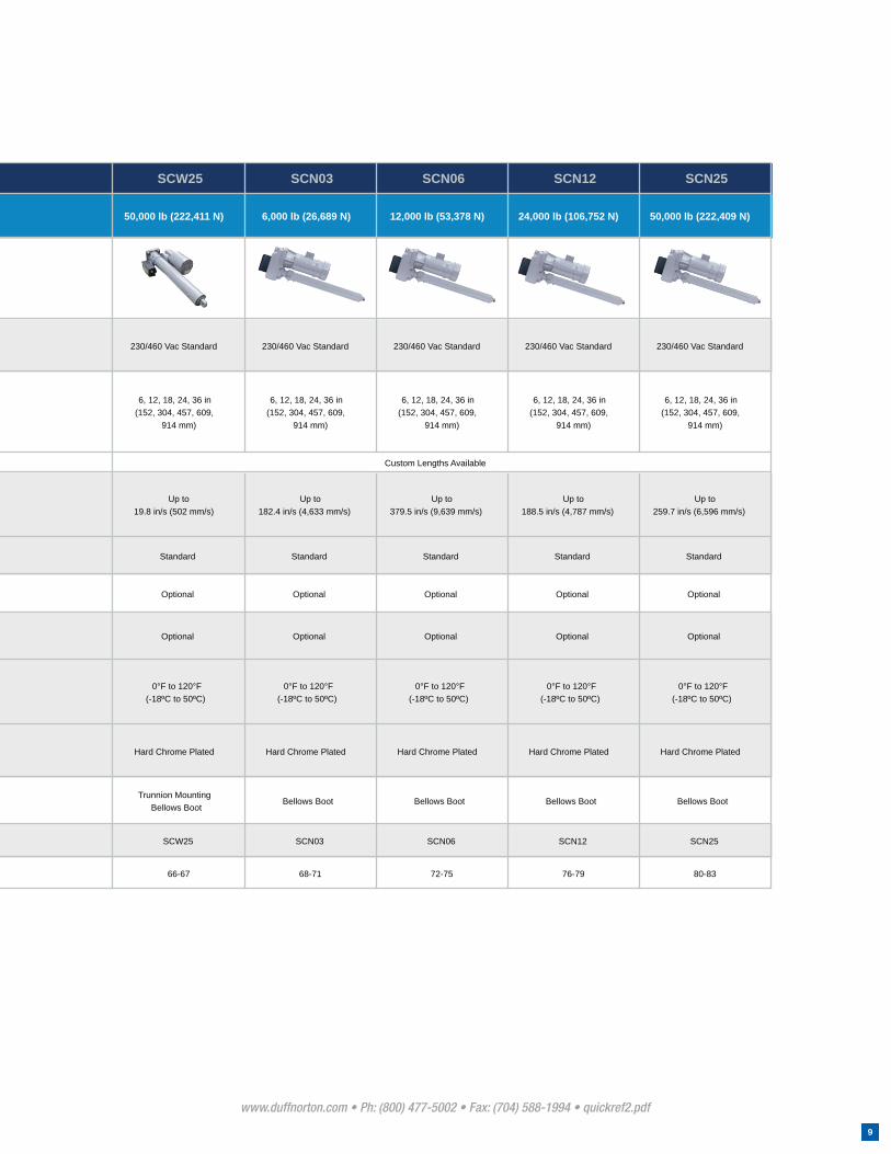
SCW25 SCN03 SCN06 SCN12 SCN25
50,000 lb (222,411 N) 6,000 lb (26,689 N) 12,000 lb (53,378 N) 24,000 lb (106,752 N) 50,000 lb (222,409 N)
230/460 Vac Standard 230/460 Vac Standard 230/460 Vac Standard 230/460 Vac Standard 230/460 Vac Standard
6, 12, 18, 24, 36 in(152, 304, 457, 609,
914 mm)
6, 12, 18, 24, 36 in(152, 304, 457, 609,
914 mm)
6, 12, 18, 24, 36 in(152, 304, 457, 609,
914 mm)
6, 12, 18, 24, 36 in(152, 304, 457, 609,
914 mm)
6, 12, 18, 24, 36 in(152, 304, 457, 609,
914 mm)
Up to19.8 in/s (502 mm/s)
Up to182.4 in/s (4,633 mm/s)
Up to379.5 in/s (9,639 mm/s)
Up to188.5 in/s (4,787 mm/s)
Up to259.7 in/s (6,596 mm/s)
Standard Standard Standard Standard Standard
Optional Optional Optional Optional Optional
Optional Optional Optional Optional Optional
0°F to 120°F(-18ºC to 50ºC)
0°F to 120°F(-18ºC to 50ºC)
0°F to 120°F(-18ºC to 50ºC)
0°F to 120°F(-18ºC to 50ºC)
0°F to 120°F(-18ºC to 50ºC)
Hard Chrome Plated Hard Chrome Plated Hard Chrome Plated Hard Chrome Plated Hard Chrome Plated
Trunnion MountingBellows Boot
Bellows Boot Bellows Boot Bellows Boot Bellows Boot
SCW25 SCN03 SCN06 SCN12 SCN25
66-67 68-71 72-75 76-79 80-83
Custom Lengths Available

Portable LightingPROBLEM: Movie and construc-
tion crews need portable lighting
for work at night. Lighting that
is compact for travel and easily
erected on location was diffi cult
to fi nd.
SOLUTION: Duff-Norton linear ac-
tuators mounted to the skeleton
of the lighting system, allows the
lights to be drawn fl ush against
the vehicle, then fully extended on
location at the fl ip of a switch. Ad-
ditional actuators adjust the angle
of the lighting fi xtures
Tilt / Pivot
Duff-Norton linear actuators can
be used to tilt objects, fi xed at
one end, up to 180º from their
starting positions. The extension
and retraction of the actuator
causes the object to pivot about
its stationary end.
Drill Press TablePROBLEM: When work pieces of
different sizes require manual ma-
chining, it is necessary to adjust
the height of the drill press table.
Adjusting the height of the table
manually is both time consuming
and fatiguing.
SOLUTION: A Duff-Norton linear
actuator mounted under the table
allows the operator to change
the height of the table as often as
needed using either hand or foot
controls.
Lift / Lower
Duff-Norton linear actuators can
handle any lifting and lowering
application up to 2000 lbs (910
kgs). As the translating tube of
the actuator extends and retracts,
the object that the actuator is at-
tached to is raised and lowered at
a consistent speed.
Engine Assembly FixturePROBLEM: Fixture must be highly
adjustable to specifi c positions
for different procedures. The
movement of the fi xture must be
smooth and reliable.
SOLUTION: Duff-Norton linear
actuators are used to raise and
lower the assembly fi xture. This
saves assembly time, reduces
employee fatigue and work re-
lated injuries.
Position
When an application requires pe-
riodic adjustment to the position
of an object or objects, Duff-Nor-
ton linear actuators provide the
solution. The motion of the actua-
tor allows the operator to position
an object by simply pushing a
button.
APPLICATIONS
www.duffnorton.com • Ph: (800) 477-5002 • Fax: (704) 588-1994 • applications.pdf
10

Drum / Barrel LifterPROBLEM: Hazardous material
sealed in drums must be handled
and processed for disposal. It
is desirable to minimize human
involvement in the process.
SOLUTION: Two Duff-Norton
linear actuators are used in each
assembly. One operates a set
of ratchet clamps that securely
grasp the drum. The other actua-
tor lifts the drum for pouring.
Roll / Slide
When it is necessary to roll or
slide an object or a mechanical
assembly into position, a Duff-
Norton linear actuator is the an-
swer. The movement of the actua-
tor causes the clamping, rolling or
sliding of the desired object.
Industrial OvenPROBLEM: Industrial oven doors
can be very large and must often
be opened and closed on a timed
basis to allow for steady fl ow of
material in and out.
SOLUTION: A Duff-Norton linear
actuator is connected to the oven
door and operated by an elec-
tronic control system. The actua-
tor opens and closes the door to
allow materials to enter and exit
when prompted by the control
system.
Open / Close
A Duff-Norton linear actua-
tor mounted on a door, gate, or
valve allows opening and closing
operations on either a timed, or
on-demand basis. As the actua-
tor retracts, the gate is opened
at a steady rate; the extension of
the actuator returns the gate to a
closed position.
Conveyor SystemPROBLEM: The tension in con-
veyor belts must frequently be
adjusted to allow for crates of dif-
ferent sizes and to take up slack
in the system that develops with
use.
SOLUTION: A Duff-Norton linear
actuator is mounted to a roll at
one end of the conveyor system.
At the push of a button, the ac-
tuator adjusts the position of the
roll, controlling the tension in the
entire system. Actuators can also
be used to reposition conveyor
systems.
Tension
Duff-Norton linear actuators offer
a perfect solution for applications
in which tension on a conveyor
or web must be maintained and
adjusted. An actuator mounted
on a frame or roller extends and
retracts to control the tension in
the system.
www.duffnorton.com • Ph: (800) 477-5002 • Fax: (704) 588-1994 • applications.pdf
11

www.duffnorton.com • Ph: (800) 477-5002 • Fax: (704) 588-1994 • system.pdf
12
Part Number Power in Power out
TC1-2241-1221 120 Vac 24 Vdc
Controller
SYSTEM CONFIGURATION
The NEW Duff Norton linear actuator system will allow you to control up to four linear actua-tors independently. A Duff Norton linear actuator system includes linear actuators, a control-ler and a hand set for operation.
System applications can include agricultural machinery, industrial automation and outdoor power equipment.
• IP66 protection for outdoor applications
• Self locking ACME screw
• Easy assembly with plug and play technology
• Temperature Range: -13°F (-25°C) to 150°F (65°C)
• LED for power supply indication on the controller
• Electronic Overload Protection (controller)
www.duffnorton.com • Ph: (800) 477-5002 • Fax: (704) 588-1994 •system.pdf
13
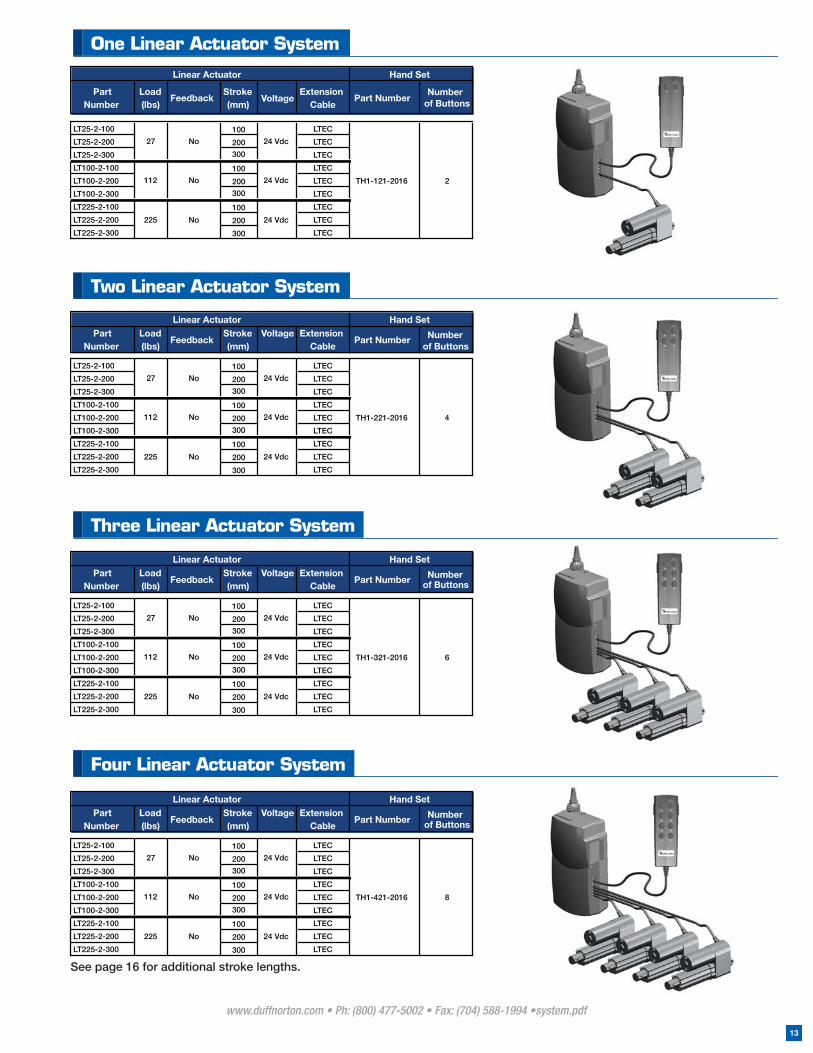
Part Number
Load (lbs)
FeedbackStroke (mm)
Voltage Extension Cable
Part Number Number of Buttons
LT25-2-100 100 LTEC
LT25-2-200 200 LTEC
LT25-2-300 300 LTEC
LT100-2-100 100 LTEC
LT100-2-200 200 LTEC
LT100-2-300 300 LTEC
LT225-2-100 100 LTEC
LT225-2-200 200 LTEC
LT225-2-300 300 LTEC
112 No
225 No
4TH1-221-201624 Vdc
24 Vdc
27 No 24 Vdc
Linear Actuator Hand Set
Part Number
Load (lbs)
FeedbackStroke (mm)
VoltageExtension
CablePart Number
Number of Buttons
LT25-2-100 100 LTEC
LT25-2-200 200 LTEC
LT25-2-300 300 LTEC
LT100-2-100 100 LTEC
LT100-2-200 200 LTEC
LT100-2-300 300 LTEC
LT225-2-100 100 LTEC
LT225-2-200 200 LTEC
LT225-2-300 300 LTEC
Linear Actuator
24 Vdc
TH1-121-2016 2
Hand Set
No27
112
24 Vdc
225
No
No
24 Vdc
Part Number
Load (lbs)
FeedbackStroke (mm)
Voltage Extension Cable
Part Number Number of Buttons
LT25-2-100 100 LTEC
LT25-2-200 200 LTEC
LT25-2-300 300 LTEC
LT100-2-100 100 LTEC
LT100-2-200 200 LTEC
LT100-2-300 300 LTEC
LT225-2-100 100 LTEC
LT225-2-200 200 LTEC
LT225-2-300 300 LTEC
Linear Actuator
TH1-321-2016 6
225 No 24 Vdc
112 No 24 Vdc
27 No 24 Vdc
Hand Set
Part Number
Load (lbs)
FeedbackStroke (mm)
Voltage Extension Cable
Part Number Number of Buttons
LT25-2-100 100 LTEC
LT25-2-200 200 LTEC
LT25-2-300 300 LTEC
LT100-2-100 100 LTEC
LT100-2-200 200 LTEC
LT100-2-300 300 LTEC
LT225-2-100 100 LTEC
LT225-2-200 200 LTEC
LT225-2-300 300 LTEC
TH1-421-2016
Linear Actuator
24 Vdc
27 No 24 Vdc
112 No 24 Vdc 8
225 No
Hand Set
See page 16 for additional stroke lengths.
One Linear Actuator System
Two Linear Actuator System
Three Linear Actuator System
Four Linear Actuator System
www.duffnorton.com • Ph: (800) 477-5002 • Fax: (704) 588-1994 • system.pdf
14
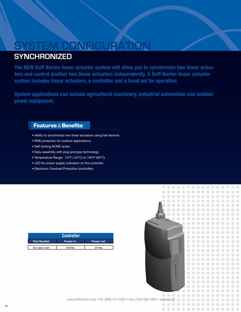
SYSTEM CONFIGURATION SYNCHRONIZED
Part Number Power in Power out
TC1-2241-1221 120 Vac 24 Vdc
Controller
The NEW Duff Norton linear actuator system will allow you to synchronize two linear actua-tors and control another two linear actuators independently. A Duff Norton linear actuator system includes linear actuators, a controller and a hand set for operation.
System applications can include agricultural machinery, industrial automation and outdoor power equipment.
• Ability to synchronize two linear actuators using hall sensors
• IP66 protection for outdoor applications
• Self locking ACME screw
• Easy assembly with plug and play technology
• Temperature Range: -13°F (-25°C) to 150°F (65°C)
• LED for power supply indication on the controller
• Electronic Overload Protection (controller)

www.duffnorton.com • Ph: (800) 477-5002 • Fax: (704) 588-1994 • system.pdf
15
Part NumberLoad (lbs)
FeedbackStroke
(mm)Voltage
ExtensionCable
Part Number
Number of Buttons
LT25-2-100H 100 N/A
LT25-2-200H 200 N/A
LT25-2-300H 300 N/A
LT100-2-100H 100 N/A
LT100-2-200H 200 N/A
LT100-2-300H 300 N/A
LT225-2-100H 100 N/A
LT225-2-200H 200 N/A
LT225-2-300H 300 N/A
LT25-2-100 100 LTEC
LT25-2-200 200 LTEC
LT25-2-300 300 LTEC
LT100-2-100 100 LTEC
LT100-2-200 200 LTEC
LT100-2-300 300 LTEC
LT225-2-100 100 LTEC
LT225-2-200 200 LTEC
LT225-2-300 300 LTEC
24 Vdc
27 Hall Sensor 24 Vdc
TH1-421-2016S 6
24 Vdc
27 No 24 Vdc
225
24 Vdc
225 No 24 Vdc
112 Hall Sensor
112 No
Hall Sensor
Hand SetLinear Actuator
Part NumberLoad (lbs)
FeedbackStroke(mm) Voltage
ExtensionCable
Part Number
Number of Buttons
LT25-2-100H 100 N/A
LT25-2-200H 200 N/A
LT25-2-300H 300 N/A
LT100-2-100H 100 N/A
LT100-2-200H 200 N/A
LT100-2-300H 300 N/A
LT225-2-100H 100 N/A
LT225-2-200H 200 N/A
LT225-2-300H 300 N/A
27 Hall Sensor 24 Vdc
Linear Actuator Hand Set
112 Hall Sensor 24 Vdc
225 Hall Sensor
2TH1-121-2016S
24 Vdc
Part NumberLoad (lbs)
FeedbackStroke(mm)
VoltageExtension
CablePart
NumberNumber
of Buttons
LT25-2-100H 100 N/A
LT25-2-200H 200 N/A
LT25-2-300H 300 N/A
LT100-2-100H 100 N/A
LT100-2-200H 200 N/A
LT100-2-300H 300 N/A
LT225-2-100H 100 N/A
LT225-2-200H 200 N/A
LT225-2-300H 300 N/A
LT25-2-100 100 LTEC
LT25-2-200 200 LTEC
LT25-2-300 300 LTEC
LT100-2-100 100 LTEC
LT100-2-200 200 LTEC
LT100-2-300 300 LTEC
LT225-2-100 100 LTEC
LT225-2-200 200 LTEC
LT225-2-300 300 LTEC
24 Vdc
TH1-321-2016S
24 Vdc
Hand SetLinear Actuator
112 Hall Sensor
27 Hall Sensor
24 Vdc
225 Hall Sensor 24 Vdc
27 No 24 Vdc
112 No 24 Vdc
4
225 No
Two Synchronized Linear Actuator System
Two Synchronized Linear Actuators plus one Independently operated Linear Actuator
Two Synchronized Linear Actuators plus two Independently operated Linear Actuator

www.duffnorton.com • Ph: (800) 477-5002 • Fax: (704) 588-1994 • LT.pdf
16
LT SERIES27 to 225 lbs
120 to 1,000 N
CAPACITY
VOLTAGE
TEMPERATURE RANGE
STATIC LOAD
STROKES
ENVIRONMENT
1,800 lbs (8,000 N)
2 to 11.8 in (50 to 300 mm)
IP66 Protection
27 to 225 lbs (120 to 1,000N)
12 or 24 VDC
-13ºF to 150ºF (-25ºC to 65ºC)
Specifications
• Limit Switches - internal, factory preset
• Self Locking Acme Screw to prevent back driving
• Zinc Die Cast Housing for strength
• Aluminum outer tube for corrosion resistance
• Keyed translating tube to prevent rotation
• Polished aluminum translating tube for smooth operation
• Warranty - 1 year, parts and labor
• Gear Driven
• Potentiometer, Hall Effect, Reed or Optical Feedback
• Signal sending Limit Switch
• Third Limit Switch
• Stainless steel translating tube
• Custom cable lengths
• Wired or wireless handsets
• AC power supply for multiple actuators
• AC controller for synchronous operation
• Custom design models
Options
* This product is used in our Linear Actuator Systems. See page 12 for details.
www.duffnorton.com • Ph: (800) 477-5002 • Fax: (704) 588-1994 • LT.pdf
17
L T S E R I E S
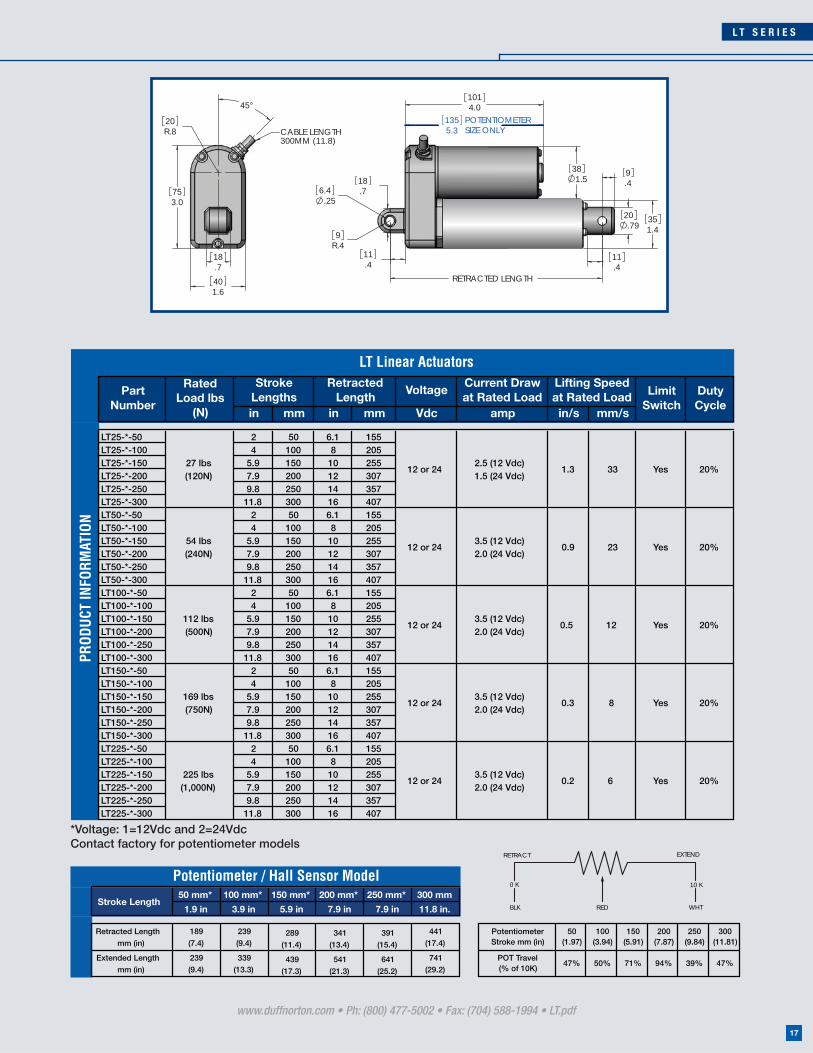
*Voltage: 1=12Vdc and 2=24VdcContact factory for potentiometer models
VoltageCurrent Draw at Rated Load
in mm in mm Vdc amp in/s mm/s
LT25-*-50 2 50 6.1 155LT25-*-100 4 100 8 205LT25-*-150 5.9 150 10 255LT25-*-200 7.9 200 12 307LT25-*-250 9.8 250 14 357LT25-*-300 11.8 300 16 407LT50-*-50 2 50 6.1 155LT50-*-100 4 100 8 205LT50-*-150 5.9 150 10 255LT50-*-200 7.9 200 12 307LT50-*-250 9.8 250 14 357LT50-*-300 11.8 300 16 407LT100-*-50 2 50 6.1 155LT100-*-100 4 100 8 205LT100-*-150 5.9 150 10 255LT100-*-200 7.9 200 12 307LT100-*-250 9.8 250 14 357LT100-*-300 11.8 300 16 407LT150-*-50 2 50 6.1 155LT150-*-100 4 100 8 205LT150-*-150 5.9 150 10 255LT150-*-200 7.9 200 12 307LT150-*-250 9.8 250 14 357LT150-*-300 11.8 300 16 407LT225-*-50 2 50 6.1 155LT225-*-100 4 100 8 205LT225-*-150 5.9 150 10 255LT225-*-200 7.9 200 12 307LT225-*-250 9.8 250 14 357LT225-*-300 11.8 300 16 407
Duty Cycle
0.5
0.3
0.2
Limit Switch
Retracted Length
Lifting Speed at Rated Load
1.3
0.9
Part Number
Rated Load lbs
(N)
Stroke Lengths
Yes 20%
12 Yes 20%
Yes 20%169 lbs (750N)
12 or 243.5 (12 Vdc) 2.0 (24 Vdc)
8
Yes 20%
54 lbs(240N)
12 or 243.5 (12 Vdc) 2.0 (24 Vdc)
23 Yes 20%
27 lbs(120N)
12 or 24
LT Linear Actuators
2.5 (12 Vdc)1.5 (24 Vdc)
33
225 lbs (1,000N)
12 or 243.5 (12 Vdc)2.0 (24 Vdc)
6
112 lbs (500N)
12 or 243.5 (12 Vdc) 2.0 (24 Vdc)
PROD
UCT
INFO
RMAT
ION
3.075
.411
.4
1.5
R9
4.0
.7
38
.25
186.4
.7920
101
11.4
9.4
1.435
RETRACTED LENGTH
CABLE LENGTH300MM (11.8)
.718
1.640
R.820
45°
5.3135 POTENTIOMETER
SIZE ONLY
50 mm* 100 mm* 150 mm* 200 mm* 250 mm* 300 mm
1.9 in 3.9 in 5.9 in 7.9 in 7.9 in 11.8 in.
Retracted Length
mm (in)
189
(7.4)
239
(9.4)289
(11.4)
341
(13.4)
391
(15.4)
441
(17.4)
Potentiometer Stroke mm (in)
50(1.97)
100(3.94)
150(5.91)
200(7.87)
250(9.84)
300(11.81)
Extended Length
mm (in)
239
(9.4)
339
(13.3)439
(17.3)
541
(21.3)
641
(25.2)
741
(29.2)
POT Travel(% of 10K)
47% 50% 71% 94% 39% 47%
Potentiometer / Hall Sensor Model
Stroke Length
0 K 10 K
BLK RED WHT
RETRACT EXTEND

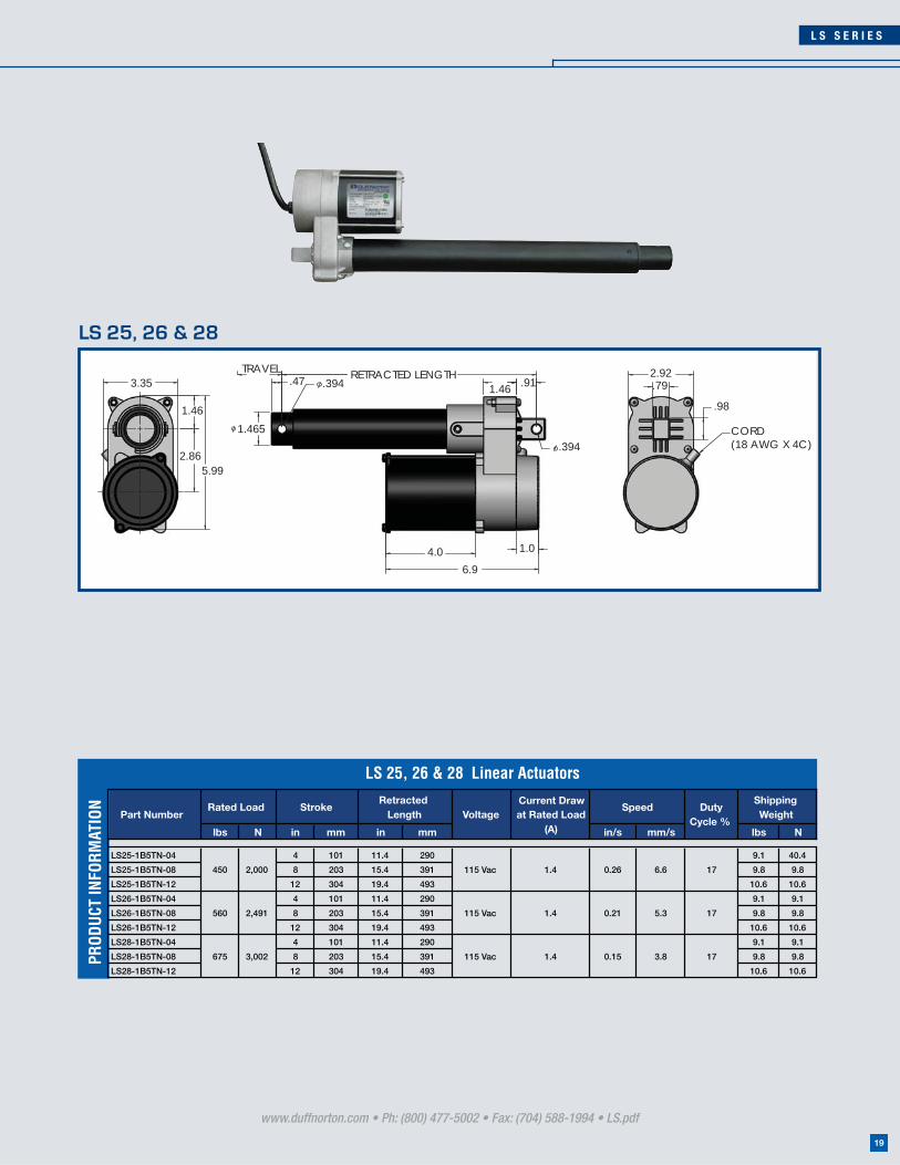
LS SERIES450 to 675 lbs
2,000 to 3,000 N
• Loading: tension (pull) or compression (push) at rated load
• AC motor thermal protection to prevent over heating
• Internal limit switches
• Onboard capacitor for AC models
• Die cast aluminum housing for strength
• Steel translating tube and outer tube
• Self locking acme screw to prevent back driving
• CE compliant and UL recognized
• Custom models available
www.duffnorton.com • Ph: (800) 477-5002 • Fax: (704) 588-1994 • LS.pdf
18
CAPACITY
VOLTAGE
SPEED
STROKES
.15 to .26 in/s (3.8 to 6.6 mm/s)
4, 8, 12, and 24 in (101, 203, 304, and 609 mm)
450 to 675 lbs (2,000 to 3,000 N)
12 VDC or 115 VAC
Specifications
L S S E R I E S
www.duffnorton.com • Ph: (800) 477-5002 • Fax: (704) 588-1994 • LS.pdf
19
lbs N in mm in mm in/s mm/s lbs N
LS25-1B5TN-04 4 101 11.4 290 9.1 40.4
LS25-1B5TN-08 8 203 15.4 391 9.8 9.8
LS25-1B5TN-12 12 304 19.4 493 10.6 10.6
LS26-1B5TN-04 4 101 11.4 290 9.1 9.1
LS26-1B5TN-08 8 203 15.4 391 9.8 9.8
LS26-1B5TN-12 12 304 19.4 493 10.6 10.6
LS28-1B5TN-04 4 101 11.4 290 9.1 9.1
LS28-1B5TN-08 8 203 15.4 391 9.8 9.8
LS28-1B5TN-12 12 304 19.4 493 10.6 10.6
Rated Load
450
560
675
Current Draw at Rated Load
(A)Voltage
0.15
Speed DutyCycle %
3.8 17
5.3 17
0.26
0.211.4
3,002 115 Vac 1.4
115 Vac2,491
LS 25, 26 & 28 Linear Actuators
2,000 115 Vac 6.6 171.4
ShippingWeight
RetractedLength
StrokePart Number
PROD
UCT
INFO
RMAT
ION
TRAVEL
1.46
3.35
5.992.86
CORD (18 AWG X 4C)
.79
.98
2.92.47 .394
RETRACTED LENGTH.91
.394
6.9
1.465
1.0
1.46
4.0
LS 25, 26 & 28
www.duffnorton.com • Ph: (800) 477-5002 • Fax: (704) 588-1994 • LS.pdf
20
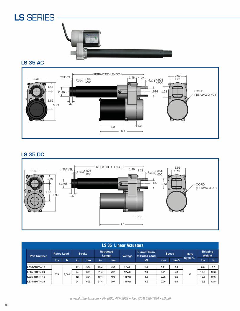
LS SERIES
3.35
1.46
5.99 .47
RETRACTED LENGTHTRAVEL
.394 - .000+.004.394 - .000
+.004
2.86
CORD(18 AWG X 4C)
2.921.73
1.73
1.221.46
1.0
1.465
6.9
4.0
.984
lbs N in mm in mm in/s mm/s lbs N
LS35-3B4TN-12 12 304 19.4 493 12Vdc 10 0.21 5.3 8.6 8.6
LS35-3B4TN-24 24 609 31.4 797 12Vdc 10 0.21 5.3 10.8 10.8
LS35-1B4TN-12 12 304 19.4 493 115Vac 1.6 0.26 6.6 10.6 10.6
LS35-1B4TN-24 24 609 31.4 797 115Vac 1.6 0.26 6.6 12.8 12.8
675 3,002 17
ShippingWeight
LS 35 Linear Actuators
Part NumberRated Load Stroke
RetractedLength Voltage
Speed DutyCycle %
Current Draw at Rated Load
(A)
3.35
1.46
5.99 .47
-.394TRAVEL
.394 - .000+.004
.000+.004
RETRACTED LENGTH
2.86
1.732.92
1.73 CORD(18 AWG X 2C)
1.46 1.22
.984
1.0
1.465
7.1
LS 35 AC
LS 35 DC

www.duffnorton.com • Ph: (800) 477-5002 • Fax: (704) 588-1994 • LS.pdf
21
L S S E R I E S
3.35
1.46
5.992.86
CORD(18 AWG X 2C)
2.92
1.13
1.0
1.0
1.47
.57
1.0 1.45
6.9
.512
RETRACTED LENGTH
1.43
lbs N in mm in mm in/s mm/s lbs N
LS48-S001 660 2,935 24 609 38.8 984 115Vac 1.4 0.15 3.8 17 21.6 21.6
Speed DutyCycle %
ShippingWeight
LS 48 Linear Actuators
Part NumberRated Load Stroke
RetractedLength Voltage
Current Draw at Rated Load
(A)
LS 48

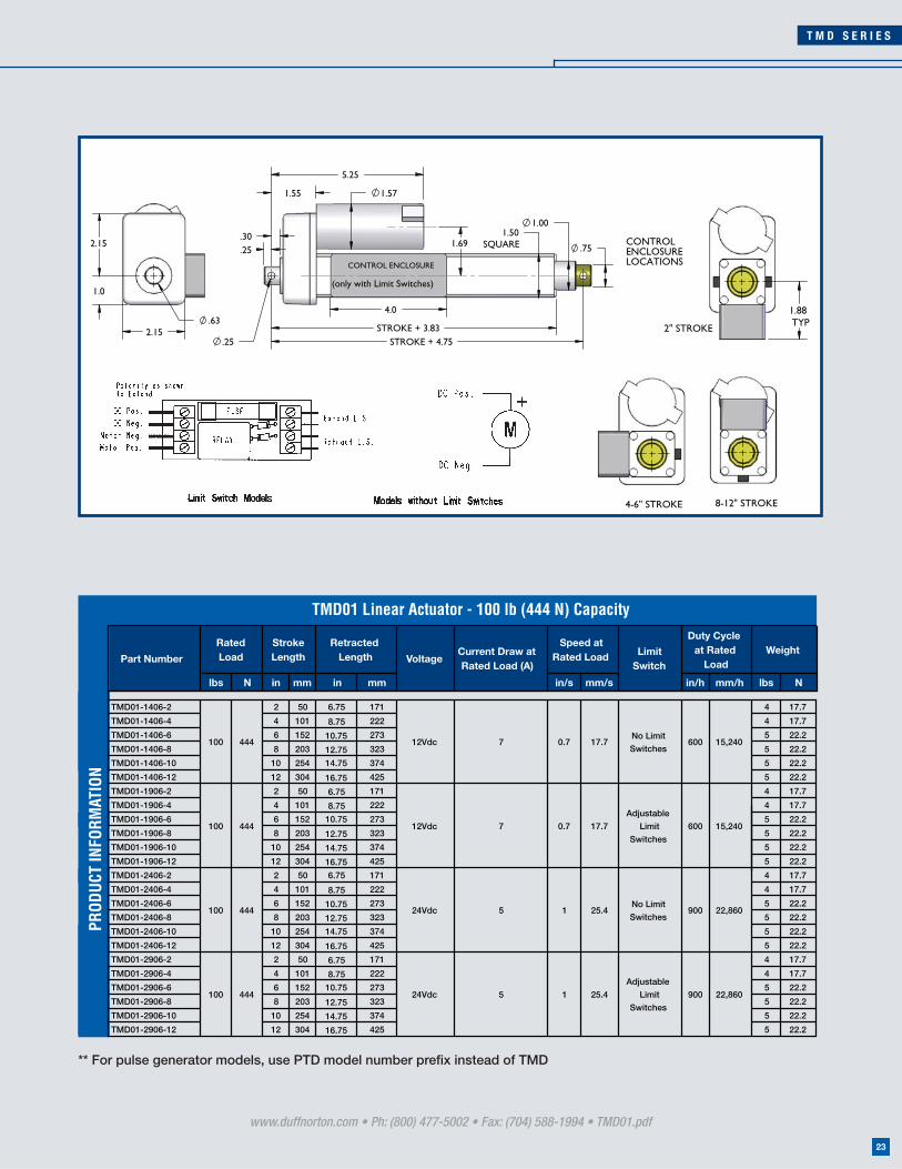
TMD01 SERIES100 lbs
444 N
CAPACITY
TEMPERATURE RANGE
STATIC LOAD
DESIGN ENVIRONMENT
300 lbs (1,332 N)
Acme Screw IP50 Protection standard
100 lbs (444 N)
-20ºF to 120ºF (-29ºC to 50ºC)
Specifications
• Compact design
• Timing belt drive for quiet operation
• Aluminum housing and outer tube
• Low current draw
• Double clevis mounting
• Easy to wire terminal strip (limit switch models)
• Keyed translating tube
• Permanent magnet motors - no thermal overload protection
• Adjustable Limit Switched - Includes control enclosure with fuse
• Pulse generator for feedback
(Add “PTD” prefi x)
Options
www.duffnorton.com • Ph: (800) 477-5002 • Fax: (704) 588-1994 • TMD01.pdf
22
T M D S E R I E S
www.duffnorton.com • Ph: (800) 477-5002 • Fax: (704) 588-1994 • TMD01.pdf
23
** For pulse generator models, use PTD model number prefi x instead of TMD
1.69
1.57
.25
.30
1.55
1.50SQUARE
1.00
.75
STROKE + 3.83STROKE + 4.75.25
4.0
5.25
CONTROL ENCLOSURE
(only with Limit Switches)1.0
2.15
2.15.63
1.88TYP2" STROKE
CONTROLENCLOSURELOCATIONS
4-6" STROKE 8-12" STROKE
lbs N in mm in mm in/s mm/s in/h mm/h lbs N
TMD01-1406-2 2 50 6.75 171 4 17.7
TMD01-1406-4 4 101 8.75 222 4 17.7
TMD01-1406-6 6 152 10.75 273 5 22.2
TMD01-1406-8 8 203 12.75 323 5 22.2
TMD01-1406-10 10 254 14.75 374 5 22.2
TMD01-1406-12 12 304 16.75 425 5 22.2
TMD01-1906-2 2 50 6.75 171 4 17.7
TMD01-1906-4 4 101 8.75 222 4 17.7
TMD01-1906-6 6 152 10.75 273 5 22.2
TMD01-1906-8 8 203 12.75 323 5 22.2
TMD01-1906-10 10 254 14.75 374 5 22.2
TMD01-1906-12 12 304 16.75 425 5 22.2
TMD01-2406-2 2 50 6.75 171 4 17.7
TMD01-2406-4 4 101 8.75 222 4 17.7
TMD01-2406-6 6 152 10.75 273 5 22.2
TMD01-2406-8 8 203 12.75 323 5 22.2
TMD01-2406-10 10 254 14.75 374 5 22.2
TMD01-2406-12 12 304 16.75 425 5 22.2
TMD01-2906-2 2 50 6.75 171 4 17.7
TMD01-2906-4 4 101 8.75 222 4 17.7
TMD01-2906-6 6 152 10.75 273 5 22.2
TMD01-2906-8 8 203 12.75 323 5 22.2
TMD01-2906-10 10 254 14.75 374 5 22.2
TMD01-2906-12 12 304 16.75 425 5 22.2
No Limit
Switches
Adjustable
Limit
Switches
No Limit
Switches
Adjustable
Limit
Switches
24Vdc
24Vdc
12Vdc
12Vdc
Duty Cycle at Rated
LoadWeightLimit
SwitchPart Number
Rated Load
Retracted Length
TMD01 Linear Actuator - 100 lb (444 N) Capacity
100 444
100 444
VoltageCurrent Draw at Rated Load (A)
Stroke Length
Speed at Rated Load
100
7
5
444
100 444
5
0.7 17.7
0.7 17.7
1 25.4
1 25.4
7 600 15,240
600 15,240
900 22,860
900 22,860
PROD
UCT
INFO
RMAT
ION
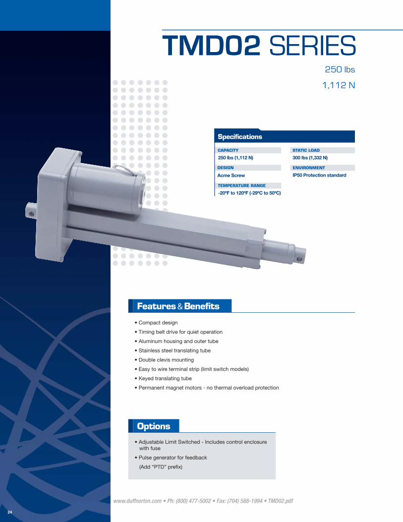
TMD02 SERIES250 lbs
1,112 N
CAPACITY
TEMPERATURE RANGE
STATIC LOAD
DESIGN ENVIRONMENT
300 lbs (1,332 N)
Acme Screw IP50 Protection standard
250 lbs (1,112 N)
-20ºF to 120ºF (-29ºC to 50ºC)
Specifications
• Compact design
• Timing belt drive for quiet operation
• Aluminum housing and outer tube
• Stainless steel translating tube
• Double clevis mounting
• Easy to wire terminal strip (limit switch models)
• Keyed translating tube
• Permanent magnet motors - no thermal overload protection
• Adjustable Limit Switched - Includes control enclosure with fuse
• Pulse generator for feedback
(Add “PTD” prefi x)
Options
www.duffnorton.com • Ph: (800) 477-5002 • Fax: (704) 588-1994 • TMD02.pdf
24

T M D S E R I E S
www.duffnorton.com • Ph: (800) 477-5002 • Fax: (704) 588-1994 • TMD02.pdf
25
** For pulse generator models, use PTD model number prefi x instead of TMD
1.50SQUARE
1.00
.75
4.0
.33
.42
1.82
6.06
2.28
1.91
STROKE + 4.1"
STROKE + 5"
CONTROL ENCLOSURE
(only with Limit Switches)
2.88
1.73
3.20.75
1.88TYP
2" STROKE
CONTROLENCLOSURELOCATIONS
4-6" STROKE 8-12" STROKE
lbs N in mm in mm in/s mm/s in/h mm/h lbs N
TMD02-1406-2 2 50 7 177 4 17.7
TMD02-1406-4 4 101 9 228 4 17.7
TMD02-1406-6 6 152 11 279 5 22.2
TMD02-1406-8 8 203 13 330 5 22.2
TMD02-1406-10 10 254 15 381 5 22.2
TMD02-1406-12 12 304 17 431 5 22.2
TMD02-1906-2 2 50 7 177 4 17.7
TMD02-1906-4 4 101 9 228 4 17.7
TMD02-1906-6 6 152 11 279 5 22.2
TMD02-1906-8 8 203 13 330 5 22.2
TMD02-1906-10 10 254 15 381 5 22.2
TMD02-1906-12 12 304 17 431 5 22.2
TMD02-2406-2 2 50 7 177 4 17.7
TMD02-2406-4 4 101 9 228 4 17.7
TMD02-2406-6 6 152 11 279 5 22.2
TMD02-2406-8 8 203 13 330 5 22.2
TMD02-2406-10 10 254 15 381 5 22.2
TMD02-2406-12 12 304 17 431 5 22.2
TMD02-2906-2 2 50 7 177 4 17.7
TMD02-2906-4 4 101 9 228 4 17.7
TMD02-2906-6 6 152 11 279 5 22.2
TMD02-2906-8 8 203 13 330 5 22.2
TMD02-2906-10 10 254 15 381 5 22.2
TMD02-2906-12 12 304 17 431 5 22.2
1,112
250 1,112No Limit
Switches7 0.4
0.4 10
10
TMD02 Linear Actuator - 250 lb (1,112 N) Capacity
250 1,112
250 1,112
VoltageCurrent Draw at Rated Load (A)
Stroke Length
Speed at Rated Load
250
Duty Cycle at Rated
LoadWeight
Limit SwitchPart NumberRated Load
Retracted Length
No Limit
Switches
Independently
Adjustable Limit
Switches
Independently
Adjustable Limit
Switches
24Vdc
24Vdc
12Vdc
12Vdc
7
4.5
4.5
0.75
0.75
19
19
360
360
675
675
9,144
9,144
17,145
17,145
PROD
UCT
INFO
RMAT
ION
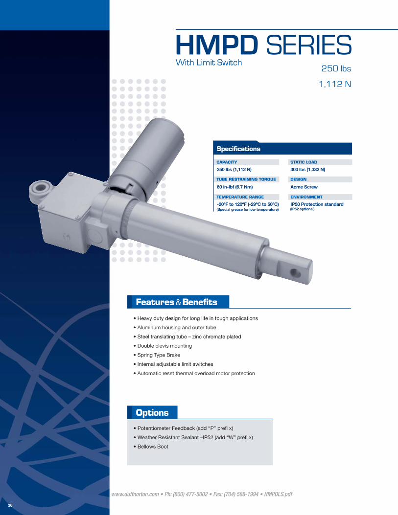
HMPD SERIES250 lbs
1,112 N
CAPACITY
TUBE RESTRAINING TORQUE
TEMPERATURE RANGE
STATIC LOAD
DESIGN
ENVIRONMENT
300 lbs (1,332 N)
Acme Screw
IP50 Protection standard
250 lbs (1,112 N)
60 in-lbf (6.7 Nm)
-20ºF to 120ºF (-29ºC to 50ºC)
Specifications
(Special grease for low temperature) (IP52 optional)
• Heavy duty design for long life in tough applications
• Aluminum housing and outer tube
• Steel translating tube – zinc chromate plated
• Double clevis mounting
• Spring Type Brake
• Internal adjustable limit switches
• Automatic reset thermal overload motor protection
• Potentiometer Feedback (add “P” prefi x)
• Weather Resistant Sealant –IP52 (add “W” prefi x)
• Bellows Boot
Options
www.duffnorton.com • Ph: (800) 477-5002 • Fax: (704) 588-1994 • HMPDLS.pdf
26
With Limit Switch
H M P D S E R I E S
www.duffnorton.com • Ph: (800) 477-5002 • Fax: (704) 588-1994 •HMPDLS.pdf
27
11/16"
1/2"
1 11/16"
(x2)
3 1/16"
1 1/4"
3/4"
1 7/8"(OPTIONAL POT)
1/2 NPT THREAD
2"
7 11/16"
4"
2 1/2"
.65
STR
OKE
+ 8
1/4
"
33/64"
1 13/16"
.85
STR
OKE
+ 6
-1/
2"
33/64"
PMMOTOR
(-)
(+)
VDC
EXTEND
RETRACT
RED
BLACK
LIMITSWITCHES
RED
YELLOW
<CONTROLS ACTUATOR>
COIL
COIL
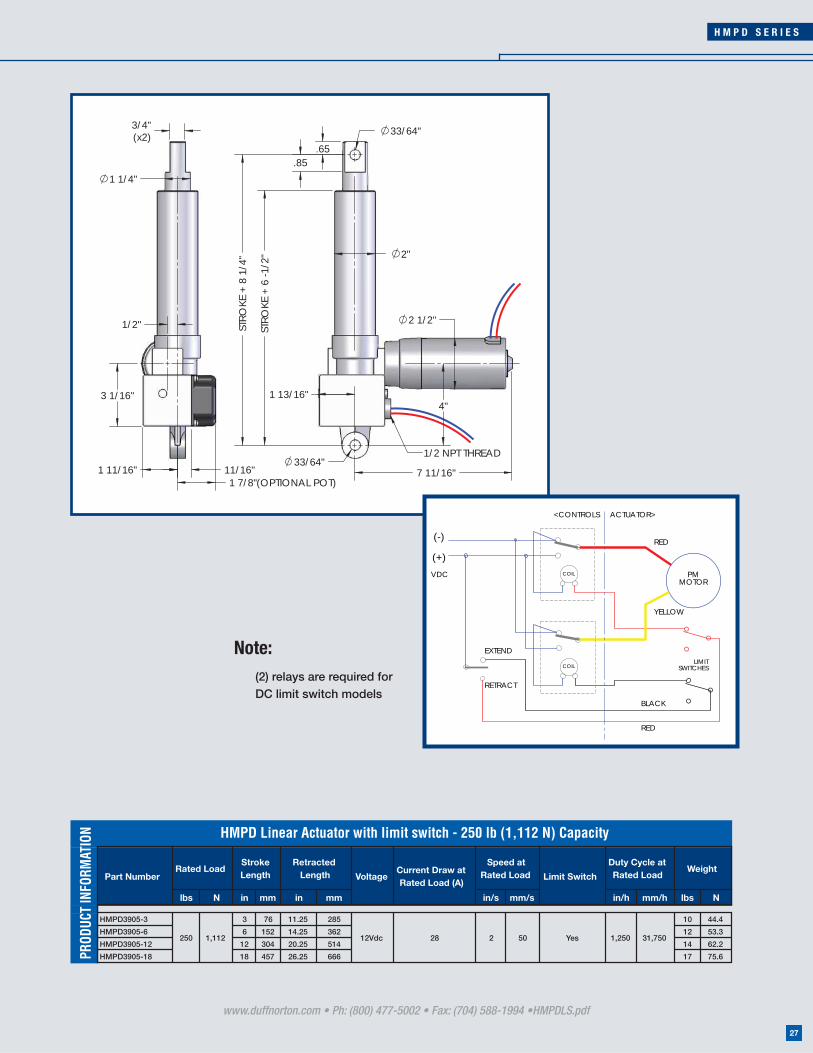
Note: (2) relays are required for
DC limit switch models
lbs N in mm in mm in/s mm/s in/h mm/h lbs N
HMPD3905-3 3 76 11.25 285 10 44.4
HMPD3905-6 6 152 14.25 362 12 53.3
HMPD3905-12 12 304 20.25 514 14 62.2
HMPD3905-18 18 457 26.25 666 17 75.6
Duty Cycle at Rated Load
WeightLimit SwitchPart Number
Rated LoadRetracted
Length
HMPD Linear Actuator with limit switch - 250 lb (1,112 N) Capacity
VoltageCurrent Draw at Rated Load (A)
Stroke Length
Speed at Rated Load
31,75012Vdc Yes250 1,112 28 2 50 1,250
PROD
UCT
INFO
RMAT
ION

HMPD SERIES250 lbs
1,112 N
CAPACITY
TUBE RESTRAINING TORQUE
TEMPERATURE RANGE
STATIC LOAD
DESIGN
ENVIRONMENT
300 lbs (1,332 N)
Acme Screw
IP50 Protection standard
250 lbs (1,112 N)
60 in-lbf (6.7 Nm)
-20ºF to 120ºF (-29ºC to 50ºC)
Specifications
(Special grease for low temperature) (IP52 optional)
• Heavy duty design for long life in tough applications
• Aluminum housing and outer tube
• Steel translating tube – zinc chromate plated
• Double clevis mounting
• Patented Spring Type Brake
• Load limiting friction disc clutch
• Automatic reset thermal overload motor protection
• Weather Resistant Sealant – IP52 (add “W” prefi x)
• Bellows Boot
• 90 degree housing clevis mounting
• Threaded end (add “T” prefi x)
Options
www.duffnorton.com • Ph: (800) 477-5002 • Fax: (704) 588-1994 • HMPDC.pdf
28
With Clutch

H M P D S E R I E S
www.duffnorton.com • Ph: (800) 477-5002 • Fax: (704) 588-1994 •HMPDC.pdf
29
1"
9/16"
1 5/8"
2 1/2"
2"
7 11/16"R21/32"
STR
OKE
+ 7
"
STR
OKE
+ 4
1/2
"
33/64"
33/64"
2"
3/4"
1 1/4"
1/2"
13/16"
3/4"
5/8"
1/2-20UNF THREAD
OPTIONAL END,LESS CLEVIS
PMMOTOR
Red
Black
+ -VDC
RetractExtend
lbs N in mm in mm in/s mm/s in/h mm/h lbs N
HMPD3405-3 3 76 11.25 285 8 35.5
HMPD3405-6 6 152 14.25 362 10 44.4
HMPD3405-12 12 304 20.25 514 12 53.3
HMPD3405-18 18 457 26.25 666 15 66.7
Speed at Rated Load
1,05028 2 50 26,67012Vdc
VoltageCurrent Draw at Rated Load (A)
Duty Cycle at Rated Load
WeightPart Number
Rated LoadRetracted
Length
HMPD Linear Actuator with Clutch - 250 lb (1,112 N) Capacity
250 1,112
Stroke Length
PROD
UCT
INFO
RMAT
ION

HMPB SERIES250 lbs
1,112 N
CAPACITY
TUBE RESTRAINING TORQUE
TEMPERATURE RANGE
STATIC LOAD
DESIGN
ENVIRONMENT
300 lbs (1,332 N)
Acme Screw
IP50 Protection standard
250 lbs (1,112 N)
60 in-lbf (6.7 Nm)
-20ºF to 120ºF (-29ºC to 50ºC)
Specifications
(Special grease for low temperature) (IP52 optional)
• Heavy duty design for long life in tough applications
• Aluminum housing and outer tube
• Steel translating tube – zinc chromate plated
• Double clevis mounting
• Bi-directional Ball Type Brake
• Internal adjustable limit switches
• Automatic reset thermal overload motor protection
• Weather Resistant Sealant – IP52 (add “W” prefi x)
• Potentiometer (add “P” prefi x)
• Capacitor (see table)
• Bellows Boot
Options
www.duffnorton.com • Ph: (800) 477-5002 • Fax: (704) 588-1994 • HMPB250.pdf
30

H M P B S E R I E S
www.duffnorton.com • Ph: (800) 477-5002 • Fax: (704) 588-1994 •HMPB250.pdf
31
4"
.65
.85
2"
8"
3 7/16"
R21/32"
STR
OKE
+ 6
1/2
"
STR
OKE
+ 8
1/4
"
1 13/16"
33/64"
33/64"
1/2 NPTTHREADEDHOLE (x2)
3/4"(x2)
1 1/4"
3 1/16"
1/2"
1 11/16" 11/16"
1 7/8" (OPTIONAL POT)
Note: For all AC motors, a capacitor is required. The capacitor can be supplied by the customer or by Duff-Norton.
Motor
Rod
L1
L2
Extend
Retractcam
White
Black
RedGear
cam
LINECapacitor
White
<Actuator Controls>
AC
Black
LimitSwitches
lbs N in mm in mm in/s mm/s in/h mm/h lbs N
HMPB3905-3 3 76 11.25 285 11 48.9
HMPB3905-6 6 152 14.25 362 13 57.8
HMPB3905-12 12 304 20.25 514 16 71.1
HMPB3905-18 18 457 26.25 666 18 80.0
PHMPB3905-3 3 76 11.25 285 12 53.3
PHMPB3905-6 6 152 14.25 362 14 62.2
PHMPB3905-12 12 304 20.25 514 17 75.6
PHMPB3905-18 18 457 26.25 666 19 84.5
35.5
HMPB Linear Actuator with limit switch - 250 lb (1,112 N) Capacity
VoltageCurrent Draw at Rated Load (A)
Stroke Length
Speed at Rated Load
Duty Cycle at Rated
LoadWeight
PotentiometerPart NumberRated Load
Retracted Length
5 1.4250 1,112115 Vac
(60 Hz)No35.5
250 1,112
500 12,700
500 12,7005115 Vac
(60 Hz)Yes1.4
PROD
UCT
INFO
RMAT
ION

HSPB SERIES250 lbs
1,112 N
CAPACITY
TUBE RESTRAINING TORQUE
TEMPERATURE RANGE
STATIC LOAD
DESIGN
ENVIRONMENT
300 lbs (1,332 N)
Acme Screw
IP50 Protection standard
250 lbs (1,112 N)
60 in-lbf (6.7 Nm)
-20ºF to 120ºF (-29ºC to 50ºC)
Specifications
(Special grease for low temperature) (IP52 optional)
• Heavy duty design for long life in tough applications
• Aluminum housing and outer tube
• Steel translating tube – zinc chromate plated
• Double clevis mounting
• Bidirectional Ball Type Brake
• Load limiting friction disc clutch
• Automatic reset thermal overload motor protection
• Weather Resistant Sealant – IP52 (add “W” prefi x)
• Capacitor (see table)
• Bellows Boot
• Thread end (add”T” prefi x)
Options
www.duffnorton.com • Ph: (800) 477-5002 • Fax: (704) 588-1994 • HSPB.pdf
32

H S P B S E R I E S
www.duffnorton.com • Ph: (800) 477-5002 • Fax: (704) 588-1994 •HSPB.pdf
33
STR
OKE
+ 7
"
STR
OKE
+ 4
1/2
"
2"
2"
9/16"
1"
33/64"
8"
1 5/8"
R21/32"
1 3/8"
33/64"
3 7/16"1/2"
13/16"
3/4"
1 1/4"
3/4"
5/8"
1/2-20UNF THREAD
OPTIONAL END,LESS CLEVIS
1/2-NPTTHREADEDHOLE
Note: For all AC motors, a capacitor is required. The capacitor can be supplied by the customer or by Duff-Norton.
Capacitor
Retract
Motor
<Actuator Controls>
Extend
AC
White
LINEL2
L1
Black
White
Black
Red
lbs N in mm in mm in/s mm/s in/h mm/h lbs N
HSPB3405-3 3 76 10 254 10 44.4
HSPB3405-6 6 152 13 330 12 53.3
HSPB3405-12 12 304 19 482 14 62.2
HSPB3405-18 18 457 25 635 17 75.6
500 12,700
Rated LoadRetracted
LengthPart Number
115 Vac
(60 Hz)250 1,112 35.5
Current Draw at Rated
Load (A)
5.1 1.4
HSPB Linear Actuator with limit switch - 250 lb (1,112 N) Capacity
Voltage
Stroke Length
Speed at Rated Load
Duty Cycle at Rated Load
Weight
PROD
UCT
INFO
RMAT
ION
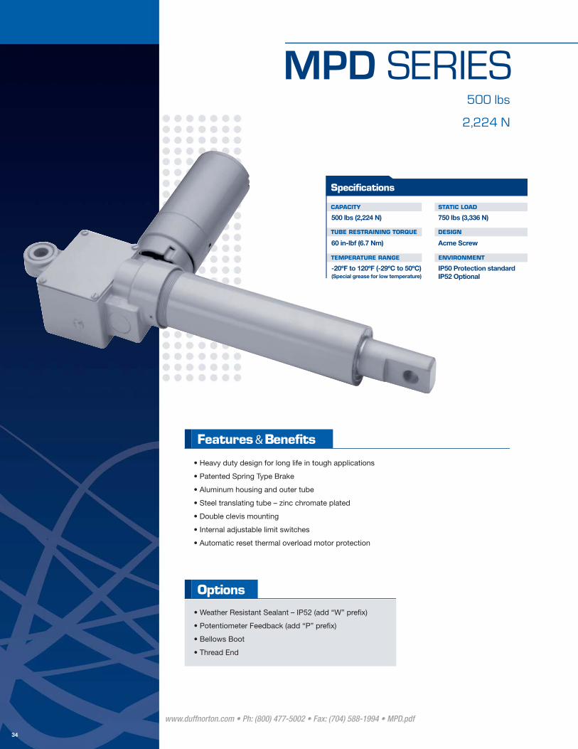
MPD SERIES500 lbs
2,224 N
• Heavy duty design for long life in tough applications
• Patented Spring Type Brake
• Aluminum housing and outer tube
• Steel translating tube – zinc chromate plated
• Double clevis mounting
• Internal adjustable limit switches
• Automatic reset thermal overload motor protection
• Weather Resistant Sealant – IP52 (add “W” prefi x)
• Potentiometer Feedback (add “P” prefi x)
• Bellows Boot
• Thread End
Options
www.duffnorton.com • Ph: (800) 477-5002 • Fax: (704) 588-1994 • MPD.pdf
34
CAPACITY
TUBE RESTRAINING TORQUE
TEMPERATURE RANGE
STATIC LOAD
DESIGN
ENVIRONMENT
750 lbs (3,336 N)
Acme Screw
IP50 Protection standardIP52 Optional
500 lbs (2,224 N)
60 in-lbf (6.7 Nm)
-20ºF to 120ºF (-29ºC to 50ºC)
Specifications
(Special grease for low temperature)

M P D S E R I E S
www.duffnorton.com • Ph: (800) 477-5002 • Fax: (704) 588-1994 • MPD.pdf
35
11/16"
1/2"
1 11/16"
(x2)
3 1/16"
1 1/4"
3/4"
1 7/8"(OPTIONAL POT)
1/2 NPT THREAD
2"
7 11/16"
4"
2 1/2"
.65
STR
OKE
+ 8
1/4
"
33/64"
1 13/16"
.85
STR
OKE
+ 6
-1/
2"
33/64"
PMMOTOR
(-)
(+)
VDC
EXTEND
RETRACT
RED
BLACK
LIMITSWITCHES
RED
YELLOW
<CONTROLS ACTUATOR>
COIL
COIL
Note: (2) relays are required for
DC limit switch models
lbs N in mm in mm in/s mm/s in/h mm/h lbs N
MPD6905-3 3 76.2 11.25 285.7 8A@ 100 lbs (444 N) 13 57.8
MPD6905-6 6 152.4 14.25 361.9 13A@ 250 lbs (1,112 N) 15 66.7
MPD6905-12 12 304.8 20.25 514.3 18 80.0
MPD6905-18 18 457.2 26.25 666.7 20 88.9
MPD6904-3 3 76.2 11.25 285.7 4A@ 100 lbs (444 N) 13 57.8
MPD6904-6 6 152.4 14.25 361.9 7A@ 250 lbs (1,112 N) 15 66.7
MPD6904-12 12 304.8 20.25 514.3 18 80.0
MPD6904-18 18 457.2 26.25 666.7 20 88.9
Duty Cycle at Rated
Load
500
510
WeightLimit Switch
Part Number
Rated LoadRetracted
Length VoltageCurrent Draw at Rated
Load (A)
Stroke Length
12,954
500 lbs (2,224 N)
500 lbs (2,224 N)
0.75
0.85
Speed at Rated Load
MPD Linear Actuator - 500 lb (2,224 N) Capacity
Yes
Yes21.524 Vdc
19.012 Vdc500
500
2,224
2,224
12,700
23A@
12A@PROD
UCT
INFO
RMAT
ION
Clutch models are available upon request

HMPB SERIES500 lbs
2,224 N
• Heavy duty design for long life in tough applications
• Bi-directional Ball Type Brake
• Aluminum housing and outer tube
• Steel translating tube – zinc chromate plated
• Double clevis mounting
• Internal adjustable limit switches
• Automatic reset thermal overload motor protection
• Potentiometer (add “P” prefi x)
• Capacitor (see table)
• Weather Resistant Sealant – IP52 (add “W” prefi x)
• Bellows Boot
• Threaded End
Options
www.duffnorton.com • Ph: (800) 477-5002 • Fax: (704) 588-1994 • HMPB500.pdf
36
CAPACITY
TUBE RESTRAINING TORQUE
TEMPERATURE RANGE
STATIC LOAD
DESIGN
ENVIRONMENT
750 lbs (3,336 N)
Acme Screw
IP50 Protection standardIP52 Optional
500 lbs (2,224 N)
60 in-lbf (6.7 Nm)
-20ºF to 120ºF (-29ºC to 50ºC)
Specifications
(Special grease for low temperature)

H M P B S E R I E S
www.duffnorton.com • Ph: (800) 477-5002 • Fax: (704) 588-1994 • HMPB500.pdf
37
4"
.65
.85
2"
8"
3 7/16"
R21/32"
STR
OKE
+ 6
1/2
"
STR
OKE
+ 8
1/4
"
1 13/16"
33/64"
33/64"
1/2 NPTTHREADEDHOLE (x2)
3/4"(x2)
1 1/4"
3 1/16"
1/2"
1 11/16" 11/16"
1 7/8" (OPTIONAL POT)
Motor
Rod
L1
L2
Extend
Retractcam
White
Black
RedGear
cam
LINECapacitor
White
<Actuator Controls>
AC
Black
LimitSwitches
Potenti-ometer
Capacitor
lbs N in mm in mm in/s mm/s in/h mm/h lbs N
HMPB6905-3 3 76.2 11.25 285.7 11 48.9
HMPB6905-6 6 152.4 14.25 361.9 13 57.8
HMPB6905-12 12 304.8 20.25 514.3 16 71.1
HMPB6905-18 18 457.2 26.25 666.7 18 80
PHMPB6905-3 3 76.2 11.25 285.7 12 53.3
PHMPB6905-6 6 152.4 14.25 361.9 14 62.2
PHMPB6905-12 12 304.8 20.25 514.3 17 75.6
PHMPB6905-18 18 457.2 26.25 666.7 19 84.5
Limit Switch
Current Draw at Rated
Load (A)
Rated Load
Duty Cycle at Rated
Load
500
500
WeightSpeed at
Rated Load
1.33
500
Stroke Length
2,224
Retracted Length
HMPB Linear Actuator - 500 lb (2,224 N) Capacity
Yes No5.5 33.7115Vac
(60 Hz)2,224500
Part Number Voltage
SK6405-7-3
(64-72 MFD)
SK6405-7-3
(64 - 72 MFD)12,700
115Vac
(60 Hz)Yes Yes33.75.5 12,7001.33
PROD
UCT
INFO
RMAT
ION
Clutch models are available upon request

SPB SERIES500 lbs Clutch
2,224 N Clutch
• Heavy duty design for long life in tough applications
• Patented Spring Type Brake
• Aluminum housing and outer tube
• Steel translating tube – zinc chromate plated
• Double clevis mounting
• Load limiting friction disc clutch
• Automatic reset thermal overload motor protection
• Capacitor (see table) - Standard on 220 VAC 50 hz model
• Weather Resistant Sealant – IP52 (add “W” prefi x)
• Bellows Boot
• Thread end (add “T” prefi x)
Options
www.duffnorton.com • Ph: (800) 477-5002 • Fax: (704) 588-1994 • SPB.pdf
38
CAPACITY
TUBE RESTRAINING TORQUE
TEMPERATURE RANGE
STATIC LOAD
DESIGN
ENVIRONMENT
750 lbs (3,336 N)
Acme Screw
IP50 Protection standardIP52 Optional
500 lbs (2,224 N)
60 in-lbf (6.7 Nm)
-20ºF to 120ºF (-29ºC to 50ºC)
Specifications
(Special grease for low temperature)

S M B S E R I E S
STR
OKE
+ 7
"
STR
OKE
+ 4
1/2
"
2"
2"
9/16"
1"
33/64"
8"
1 5/8"
R21/32"
1 3/8"
33/64"
3 7/16"1/2"
13/16"
3/4"
1 1/4"
3/4"
5/8"
1/2-20UNF THREAD
OPTIONAL END,LESS CLEVIS
1/2-NPTTHREADEDHOLE
Capacitor
Retract
Motor
<Actuator Controls>
Extend
AC
White
LINEL2
L1
Black
White
Black
Red
www.duffnorton.com • Ph: (800) 477-5002 • Fax: (704) 588-1994 • SPB.PDF
39
Part Number ClutchHigh
Speed Motor
Capacitor
lbs N in mm in mm in/s mm/s in/h mm/h lbs N
SPB6405-3 3 76.2 10 254.0 10 44.4
SPB6405-6 6 152.4 13 330.2 12 53.3
SPB6405-12 12 304.8 19 482.6 14 62.2
SPB6405-18 18 457.2 25 635.0 17 75.6
SPB7405-3 3 76.2 10 254.0 10 44.4
SPB7405-6 6 152.4 13 330.2 12 53.3
SPB7405-12 12 304.8 19 482.6 14 62.2
SPB7405-18 18 457.2 25 635.0 17 75.6
HSPB6405-3 3 76.2 10 254.0 10 44.4
HSPB6405-6 6 152.4 13 330.2 12 53.3
HSPB6405-12 12 304.8 19 482.6 14 62.2
HSPB6405-18 18 457.2 25 635.0 17 75.6
500
Weight lbs (N)
Duty Cycle at Rated
Load
500
440
Speed at Rated Load
0.58
0.51
1.3
14.7
Stroke Length
Retracted Length
Current Draw at Rated
Load (A)
Voltage
220 Vac
(50 Hz)
115 Vac
(60 Hz)
115 Vac
(60 Hz)
Rated Load
500
500
500
2,224
2,224
2,224
12,700
12.91 11,176
NoYes
No
2.1
Yes
Yes
Yes
SPB Series Clutch Model 500 lb (2,224 N) Capacity
SK6405-7-1
(28-33 MFD)
SK6405-7-10
(28-33 MFD)
SK6405-7-3
(64-72 MFD)33.05.5 12,700PR
ODUC
T IN
FORM
ATIO
N

TAC SERIES500 lbs Clutch
2,224 N Clutch
• Heavy duty design for long life in tough applications
• Aluminum housing and outer tube
• Stainless steel translating tube
• Double clevis mounting
• Load limiting ball detent clutch
• Automatic reset thermal overload motor protection
• Bellows boot
Options
www.duffnorton.com • Ph: (800) 477-5002 • Fax: (704) 588-1994 • TAC.pdf
40
CAPACITY
TUBE RESTRAINING TORQUE
TEMPERATURE RANGE
STATIC LOAD
DESIGN
ENVIRONMENT
1,000 lbs (4,448 N)
Acme Screw
IP50 Protection standard
500 lbs (2,224 N)
40 in-lbf (4.5 Nm)
-20ºF to 120ºF (-29ºC to 50ºC)
Specifications
(Special grease for low temperature)
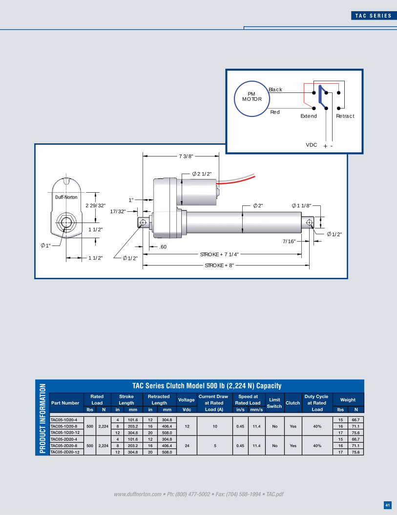
7/16"
1 1/8"2"17/32"
.60
1"
STROKE + 7 1/4"
STROKE + 8"
2 1/2"
7 3/8"
1/2"
1/2"
2 29/32"
1 1/2"
1"
1 1/2"
Duff-Norton
PMMOTOR
Red
Black
+ -VDC
RetractExtend
T A C S E R I E S
www.duffnorton.com • Ph: (800) 477-5002 • Fax: (704) 588-1994 • TAC.pdf
1541
Voltage
lbs N in mm in mm Vdc in/s mm/s lbs N
TAC05-1D20-4 4 101.6 12 304.8 15 66.7
TAC05-1D20-8 8 203.2 16 406.4 16 71.1
TAC05-1D20-12 12 304.8 20 508.0 17 75.6
TAC05-2D20-4 4 101.6 12 304.8 15 66.7
TAC05-2D20-8 8 203.2 16 406.4 16 71.1
TAC05-2D20-12 12 304.8 20 508.0 17 75.6
WeightCurrent Draw
at Rated Load (A)
Limit Switch
ClutchDuty Cycle
at Rated Load
Speed at Rated Load
Stroke Length
Retracted Length
Rated Load
500
500
Part Number
2,224
TAC Series Clutch Model 500 lb (2,224 N) Capacity
12 No Yes0.45
0.4524
40%
40%
2,224 10
11.4
11.4
5 YesNo
PROD
UCT
INFO
RMAT
ION

TAL SERIES1,000 lbs
4,448 N
• Heavy duty design for long life in tough applications
• Adjustable limit switches on motor end save space
• Aluminum housing and outer tube
• Stainless steel translating tube
• Double clevis mounting
• Automatic reset thermal overload motor protection
• Potentiometer feedback
• Capacitor (see table)
• Bellows Boot
Options
www.duffnorton.com • Ph: (800) 477-5002 • Fax: (704) 588-1994 • TAL.PDF
42
CAPACITY
TUBE RESTRAINING TORQUE
TEMPERATURE RANGE
STATIC LOAD
DESIGN
ENVIRONMENT
2,000 lbs (8,896 N)
Acme Screw
IP50 Protection standard
1,000 lbs (8,896 N)
80 in-lbf (9 Nm)
-20ºF to 120ºF (-29ºC to 50ºC)
Specifications
(Special grease for low temperature)

T A L S E R I E S
www.duffnorton.com • Ph: (800) 477-5002 • Fax: (704) 588-1994 • TAL.pdf
43
7/16"
1 1/8"
2"
17/32"
.60
1"
STROKE + 7 1/4"
STROKE + 8"
12"
1/2"
1/2"
2 29/32"
1 1/2"
1"
1 1/2"
Duff-Norton
3 7/16"
AC Power
Common
Extend
Retract
MotorRun
Capacitor
White
Black
Red
LowerSwitch
UpperSwitch
Actuator Enclosure
lbs N in mm in mm in/s mm/s lbs N
TAL10-1A20-4 4 101.6 12 304.8 19 84.5
TAL10-1A20-8 8 203.2 16 406.4 21 93.4
TAL10-1A20-12 12 304.8 20 508.0 21 93.4
TAL10-2A20-4 4 101.6 12 304.8 19 84.5
TAL10-2A20-8 8 203.2 16 406.4 21 93.4
TAL10-2A20-12 12 304.8 20 508.0 21 93.4
CapacitorDuty Cycle at Rated
Load
WeightPart Number
Speed at Rated Load
0.43
0.45 /0.37
Limit Switch
Voltage
1,000
1,000
Current Draw at Rated Load
(A)
Rated Load
Stroke Length
Retracted Length
2.0/2.5
TAL Linear Actuator 1,000 lb (4,448 N) Capacity
17.5%
17% (14%)
SK6405-7-15
(50 MFD)
SK6405-7-14
(15 MFD)
4,448
4,448
115 Vac
(60 Hz)4
220 / 230 Vac
(50 / 60 Hz)Yes
10.9 Yes
11.4/9.4PR
ODUC
T IN
FORM
ATIO
N
Clutch models are available upon request
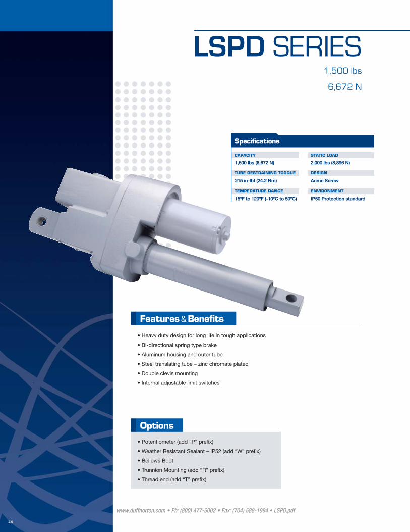
LSPD SERIES1,500 lbs
6,672 N
CAPACITY
TUBE RESTRAINING TORQUE
TEMPERATURE RANGE
STATIC LOAD
DESIGN
ENVIRONMENT
2,000 lbs (8,896 N)
Acme Screw
IP50 Protection standard
1,500 lbs (6,672 N)
215 in-lbf (24.2 Nm)
15ºF to 120ºF (-10ºC to 50ºC)
Specifications
• Heavy duty design for long life in tough applications
• Bi-directional spring type brake
• Aluminum housing and outer tube
• Steel translating tube – zinc chromate plated
• Double clevis mounting
• Internal adjustable limit switches
• Potentiometer (add “P” prefi x)
• Weather Resistant Sealant – IP52 (add “W” prefi x)
• Bellows Boot
• Trunnion Mounting (add “R” prefi x)
• Thread end (add “T” prefi x)
Options
www.duffnorton.com • Ph: (800) 477-5002 • Fax: (704) 588-1994 • LSPD.pdf
44

L S P D S E R I E S
www.duffnorton.com • Ph: (800) 477-5002 • Fax: (704) 588-1994 • LSPD.pdf
45
2" 1 1/4"3/4"
1 1/2"2 1/4"
11/32"
STROKE + 14.1"STROKE + 12.3"
8 9/16"
5 5/8"
1 3/4"
3/4"
3"
3.32
14 3/8"
3/4"
OPTIONAL TRUNNION MOUNT1/2-20UNF, 1"
1/2 NPT
1"
4.6"
5 3/4"
2 3/16"
1.411.17
7/8"Thd
5/8-18UNF
OPTIONALTHREADED
END
BOTHCLEVISES
PMMOTOR
(-)
(+)
VDC
EXTEND
RETRACT
RED
BLUE
LIMITSWITCHES
BLACK
ORANGE
<CONTROLS ACTUATOR>
COIL
COIL
FUSE
Note: (2) relays are required for DC limit
switch models
lbs N in mm in mm in/s mm/s in/h mm/h lbs N
LSPD6415-3 3 76.2 17.1 434.3 29 128.9
LSPD6415-6 6 152.4 20.1 510.5 31 137.8
LSPD6415-12 12 304.8 26.1 662.9 33 146.7
LSPD6415-18 18 457.2 32.1 815.3 35 155.6
LSPD6415-24 24 609.6 38.1 967.7 37 164.5
VoltageCurrent Draw at Rated Load
(A)
6,672
Retracted Length
2712 Vdc
Speed at Rated Load
0.43
Limit Switch
Duty Cycle at Rated Load
410Yes
Rated Load
1,500
Stroke Length
Part Number
LSPD Linear Actuator 1,500 lb (6,672 N) Capacity
10,41410.9
Weight
PROD
UCT
INFO
RMAT
ION
Clutch models are available upon request

SPA SERIES1,500 lbs
6,672 N
• Heavy duty design for long life in tough applications
• Built in capacitor included
• Bi-directional spring type brake
• Aluminum housing and outer tube
• Steel translating tube – zinc chromate plated
• Double clevis mounting
• Internal adjustable limit switches
• Automatic reset thermal overload motor protection
• Potentiometer Feedback
• Weather Resistant Sealant – IP52 (add “W” prefi x)
• Bellows Boot
• Trunnion Mounting (add “R” prefi x)
• Thread end (add “T” prefi x)
Options
www.duffnorton.com • Ph: (800) 477-5002 • Fax: (704) 588-1994 • SPA1500.pdf
46
CAPACITY
TUBE RESTRAINING TORQUE
TEMPERATURE RANGE
STATIC LOAD
DESIGN
ENVIRONMENT
2,000 lbs (8,896 N)
Acme Screw
IP50 Protection standard
1,500 lbs (6,672 N)
215 in-lbf (24.2 Nm)
15ºF to 120ºF (-10ºC to 50ºC)
Specifications
S P A S E R I E S
www.duffnorton.com • Ph: (800) 477-5002 • Fax: (704) 588-1994 • SPA1500.pdf
1547
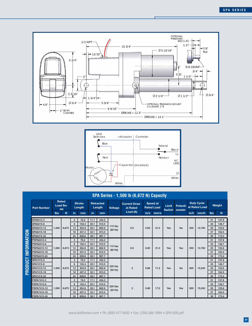
2"3.32
3 13/16"
1 1/4"
3/4"
1 1/2"2 1/4"
11/32"
STROKE + 14.1"STROKE + 12.3"
8 9/16"
5 5/8"
1 3/4"
3/4"
3/4"
15 3/4"
OPTIONAL TRUNNION MOUNT1/2-20UNF, 1"
1/2 NPT
1"
4.6"
5 3/4"
2 3/16"
1.411.17
7/8"Thd
5/8-18UNF
OPTIONALTHREADED
END
BOTHCLEVISES
White
Blue
Black
<Actuator Controls>Limit
L1
L2
Extend
White
Motor
RetractAC
Switches
LINE
Red
Capacitor (included)
lbs N in mm in mm in/s mm/s in/h mm/h lbs N
SPA6415-3 3 76.2 17.1 434.3 31 137.8
SPA6415-6 6 152.4 20.1 510.5 33 146.7
SPA6415-12 12 304.8 26.1 662.9 35 155.6
SPA6415-18 18 457.2 32.1 815.3 37 164.5
SPA6415-24 24 609.6 38.1 967.7 39 173.4
PSPA6415-3 3 76.2 17.1 434.3 31 137.8
PSPA6415-6 6 152.4 20.1 510.5 33 146.7
PSPA6415-12 12 304.8 26.1 662.9 35 155.6
PSPA6415-18 18 457.2 32.1 815.3 37 164.5
PSPA6415-24 24 609.6 38.1 967.7 39 173.4
SPA7415-3 3 76.2 17.1 434.3 31 137.8
SPA7415-6 6 152.4 20.1 510.5 33 146.7
SPA7415-12 12 304.8 26.1 662.9 35 155.6
SPA7415-18 18 457.2 32.1 815.3 37 164.5
SPA7415-24 24 609.6 38.1 967.7 39 173.4
PSPA7415-3 3 76.2 17.1 434.3 31 137.8
PSPA7415-6 6 152.4 20.1 510.5 33 146.7
PSPA7415-12 12 304.8 26.1 662.9 35 155.6
PSPA7415-18 18 457.2 32.1 815.3 37 164.5
PSPA7415-24 24 609.6 38.1 967.7 39 173.4
Yes 12,700
SPA Series - 1,500 lb (6,672 N) Capacity
115 Vac
(60 Hz)6.5 21.0 Yes No 12,700
Rated Load lbs
(N)
No 15,240
115 Vac
(60 Hz)6.5 21.0
220 Vac
(50 Hz)2 17.2 Yes
Yes
Yes 15,240
6,672
6,672
6,672
6,672220 Vac
(50 Hz)2 17.2 Yes1,500
Voltage
Stroke Length
Retracted Length
1,500 0.83
0.831,500
1,500
Limit Switch
Potenti-ometer
Part NumberCurrent Draw
at Rated Load (A)
Speed at Rated Load
600
Weight Duty Cycle
at Rated Load
500
500
6000.68
0.68
PROD
UCT
INFO
RMAT
ION

SPA SERIES2,000 lbs
8,896 N
• Heavy duty design for long life in tough applications
• Built in capacitor included
• Automatic set spring type brake
• Aluminum housing and outer tube
• Steel translating tube – steel zinc chromate plated
• Double clevis mounting
• Internal adjustable limit switches
• Weather Resistant Sealant – IP52 (add “W” prefi x)
• Bellows Boot
• Trunnion Mounting (add “R” prefi x)
• Potentiometer Feedback
• Thread end (add “T” prefi x)
Options
www.duffnorton.com • Ph: (800) 477-5002 • Fax: (704) 588-1994 • SPA2000.pdf
48
CAPACITY
TUBE RESTRAINING TORQUE
TEMPERATURE RANGE
STATIC LOAD
DESIGN
ENVIRONMENT
2,000 lbs (8,896 N)
Ball Screw Drive
IP50 Protection standardIP52 Optional
2,000 lbs (8,896 N)
180 in-lbf (20.3 Nm)
15ºF to 120ºF (-10ºC to 50ºC)
Specifications

S P A S E R I E S
www.duffnorton.com • Ph: (800) 477-5002 • Fax: (704) 588-1994 • SPA2000.pdf
49
2"3.32
3 13/16"
1 14 "
34 "
1 12 "
2 34 "
1132 "
STROKE + 18.9"STROKE + 16.8"
8 916 "
5 58 "
1 34 "
34 "
2 34 "
34 "
15 34 "
OPTIONAL TRUNNION MOUNT1/2-20UNF, 1"
1/2 NPT
1"
4.6"
5 34 "
2 316 "
1.411.17
.88Thd
5/8-18UNF
OPTIONALTHREADED
END
BOTHCLEVISES
White
Blue
Black
<Actuator Controls>Limit
L1
L2
Extend
White
Motor
RetractAC
Switches
LINE
Red
Capacitor (included)
lbs N in mm in mm in/s mm/s in/h mm/h lbs N
SPA6420-3 3 76.2 21.9 556.2 31 787.4
SPA6420-6 6 152.4 24.9 632.4 33 146.7
SPA6420-12 12 304.8 30.9 784.8 35 155.6
SPA6420-18 18 457.2 36.9 937.2 37 164.5
SPA6420-24 24 609.6 42.9 1089.6 39 990.6
PSPA6420-3 3 76.2 21.9 556.2 31 787.4
PSPA6420-6 6 152.4 24.9 632.4 33 146.7
PSPA6420-12 12 304.8 30.9 784.8 35 155.6
PSPA6420-18 18 457.2 36.9 937.2 37 164.5
PSPA6420-24 24 609.6 42.9 1089.6 39 990.6
SPA7420-3 3 76.2 21.9 556.2 31 787.4
SPA7420-6 6 152.4 24.9 632.4 33 146.7
SPA7420-12 12 304.8 30.9 784.8 35 155.6
SPA7420-18 18 457.2 36.9 937.2 37 164.5
SPA7420-24 24 609.6 42.9 1089.6 39 990.6
Weight
8,896
8,896
115Vac
(60 Hz)
115Vac
(60 Hz)
220 Vac
(50 Hz)2
Yes
17.2
600Yes
600
6300.68 16,002
21.8
Yes
Limit Switch
Duty Cycle at Rated Load
15,240
15,240
2,000
Current Draw at Rated Load (A)
Speed at Rated Load
0.86
0.865.1
21.85.18,896
Part Number
2,000
Stroke LengthRetracted
Length Voltage
SPA Series 2,000 lb (8,896 N) CapacityRated Load
lbs (N)
2,000
PROD
UCT
INFO
RMAT
ION
Contact factory for potentiometer models

MODULAR ACTUATORS
100 to 2,000 lbs
444 to 8,896 N
• Integral housing fl ange engineered for NEMA 56 frame motor. C-face mounting.
(NEMA 42 and 48 and IEC71 frame motor C-face mounting options available).
• Rated loads to 2,000 lbs., depending on actuator gear ratio and motor horsepower.
• Lift speeds to 170 inches per minute (varied with load and hp/rpm of motor).
• Standard travel up to 24 inches. (consult Duff-Norton engineering for longer travel options).
• Can be tandem-coupled for synchronous operation.
• Optional motors, limit switches and position indicating transducer.
• Clevis attachment accessories available for mounting: eye bracket, clevis bracket and pivot pin.
Duff-Norton Modular Actuators allow use in a wide range of applications by matching standard actuator models with AC or DC electric, air, hydraulic or explosion-proof drive units.
The rotating screw models, featuring a traveling lift nut, per-mit reliable load positioning in locations which are relatively free of dust, dirt and moisture.
Translating tube units, with an enclosed lifting screw and translating tube, are specifi ed when environmental contami-nation is anticipated.
Optional limit switches and transducers are also available for both actuator types.
WARNING: These actuators are intended for industrial use only and should not be used to lift, support
or otherwise transport people unless you have a written statement from Duff-Norton company which
authorizes the specifi c actuator unit, as used in your application, as suitable for moving people.
www.duffnorton.com • Ph: (800) 477-5002 • Fax: (704) 588-1994 • modular.pdf
50

M O D U L A R A C T U A T O R S
Clevis Accessories
Ordering Information(For special motor fl ange)
Limit Switch
www.duffnorton.com • Ph: (800) 477-5002 • Fax: (704) 588-1994 • modular.pdf
51

• Integral 56 frame, C-face mounting fl ange.
• Three-piece fl exible coupling for easy motor assembly (included).
• Four threaded holes in base for standard hydraulic cylinder, clevis end accessory attachment. Tapped 1/2 20 UNF-2B.
• Rolled thread lifting screw, with work hardened fi nish, reduces coeffi cient of friction between screw and lifting nut. Provides smooth, effi cient operation and long service.
• Steel worm and bronze gear set for quiet operation. Available in 5:1 and 20:1 ratios.
5:1 20:1 5:1 20:1 5:1 20:1 5:1 20:1 5:1 20:1 5:1 20:1lbs lbs lbs lbs lbs lbs
1725 300 700 500 1000 700 1500 170 43
1140 450 1000 700 1500 1100 2000 114 28
1725 400 900 600 1400 900 2000 86 21
1140 600 1400 900 2000 1400 2000 57 14M-2463
.875 Dia. Acme .25 Pitch
R.H. Double
1.0 Dia. Acme.25 Pitch
R.H.Single
10
20
Ratio
Rated Loads Lifting Speed in / min
M-2462 40 39 18
RatioModel
Number"T" Screw
Dia.
Turns of Worm 1" Travel
Torque lb./in. @ 1000 lb. Loads 1/3 HP Motor
RatioMotor RPM
1/2 HP Motor
Ratio
3/4 HP MotorRatioRatio
80 29 14
Rotating Machine Screw Models
PROD
UCT
INFO
RMAT
ION
Note: 1. Model M-2462 is self lowering and a motor brake should be used. 2. Model M-2463 may drift .75 in. (20:1 ratio) to 2.0 in. (5:1 ratio) when motor is shut off. If this is undesirable, a motor brake should be employed. 3. When ordering other than 56C-face actuators contact applications engineering at 800-477-5002.
ROTATING MACHINE SCREW MODELS
• Rugged, lightweight aluminum housing is corrosion resistant.
• Bronze lifting nut for longer life.
• Standard grease fi tting on housing for easy lubrication of worm gear.
• Stop-pin at end of lifting screw prevents inadvertent run-off
of lifting nut.
www.duffnorton.com • Ph: (800) 477-5002 • Fax: (704) 588-1994 • Modular.pdf
52
4.0
5.63
.500
6.75
1.16
3.00
1.250- .000+.005
2.00
.53 FULL TH'D
FOUR HOLES1/2-20 UNF-2B
NEMA 56C
3.63
2.55
1.28
1.8
2.55
1.28
.53.50
1.50
1.50
3.44
EQUALS TRAVEL + 2.5
1.710- .005+.000
1 3/8-12 UNNUT MUST BERESTRAINED FROMROTATION

Translating Tube Machine Screw Models
PROD
UCT
INFO
RMAT
ION
5:1 20:1 5:1 20:1 5:1 20:1 5:1 20:1 5:1 20:1 5:1 20:1lbs lbs lbs lbs lbs lbs
1725 300 700 500 1000 700 1500 170 43
1140 450 1000 700 1500 1100 2000 114 28
1725 400 900 600 1400 900 2000 86 21
1140 600 1400 900 2000 1400 2000 57 1480 29 14
1/2 HP Motor
Ratio
3/4 HP MotorRatio
Turns of Worm 1" Travel
Torque lb./in. @ 1000 lb. Loads 1/3 HP Motor
RatioMotor RPMRatio Ratio
Rated Loads Lifting Speed in /min
M-2464 40 39 18
RatioModel
Number"T" Screw
Dia.
M-2465
.875 Dia. Acme .25 Pitch
R.H. Double
1.0 Dia. Acme.25 Pitch
R.H.Single
10
20
Note: 1. Model M-2464 is self lowering and a motor brake should be used. 2. Model M-2465 may drift .75 in. (20:1 ratio) to 2.0 in. (5:1 ratio) when motor is shut off. If this is undesirable, a motor brake should be employed. 3. When ordering other than 56C-face actuators contact applications engineering at 800-477-5002.
2.00
1.500
.75
2.63
.75
TRAVEL + 3.25
1.50
.53
2.25
TRAVEL + 5.87
NEMA 56 Motor Flange
1/8 by 1/16 KEYWAY1 INCH LONG
1.00
6.75
.000
5.63
FLATSACROSS
+
4.00
.005
.500
2.00
TWO HOLES.53
1.250 -
3.00
FOUR HOLES1/2-20 UNF-2B.53 FULL THREAD
1.27
1.27
3.63
2.55
2.55
TRANSLATING TUBE MACHINE SCREW MODELS
• Outer aluminum tube is corrosion-resistant and protects translat-ing tube, lifting screw and nut.
• Wiper-scraper seal in end of outer tube keeps dirt out and lubri-cants in.
• Bronze guide bushing inside of outer tube reduces lateral move-ment of translating screw.
• Translating tube zinc coated for weather-resistance.
• Single or double lead lifting screw and nut for high effi ciency and long wear.
• Vent in outer tube prevents pressure build-up in the actuator
• Furnished with standard clevis end on translating tube. Threaded end is available; and on special order, depend-ing on application, any type of threaded connection may be substituted.
www.duffnorton.com • Ph: (800) 477-5002 • Fax: (704) 588-1994 • Modular.pdf
53

• Integral 56 frame, C-face mounting fl ange.
• Three-piece fl exible coupling for easy motor assembly (included).
• Four threaded holes in base for standard clevis end accessory attachment. Tapped 1/2-20 UNF-2B.
• Ball-bearing type screw and mating nut with rolling contact re-duces friction to a minimum providing capability for higher speed and longer life with less power requirement.
ROTATING BALL SCREW MODELS
• Steel worm and bronze gear set for quiet operation. Available in 5:1 and 20:1 ratios.
• Rugged, lightweight aluminum housing is corrosion resistant.
• Standard grease fi tting on housing for easy lubrication of worm gear.
• Stop-disc at end of lifting screw prevents inadvertent run-off of ball nut.
Rotating Ball Screw Models
PROD
UCT
INFO
RMAT
ION
5:1 20:1 5:1 20:1 5:1 20:1 5:1 20:1 5:1 20:1 5:1 20:1 5:1 20:1lbs lbs lbs lbs lbs lbslbs lbs
1725 100 - 200 - 300 - 500 - 345 -
1140 200 - 300 - 500 - 700 - 228 -
1725 600 1500 900 2000 1300 - 2000 - 86 21
1140 1000 - 1300 - 2000 - - - 57 1480 1.3 0.6
1/2 HP MotorRatio
1/3 HP Motor
Ratio
3/4 HP MotorRatio
Turns of Worm 1"
Travel
Torque lb./in. @ 100 lb.
Loads1/4 HP MotorRatio
Motor RPMRatio Ratio
Rated Loads Lifting Speed
in / min
BM-2462 - 5.3 -
RatioModel
Number"T" Screw
Dia.
BM-2463
1.00 Dia. x1.000 LeadBall Screw
1.0 Dia. x.250 LeadBall Screw
5
20
Note: 1. Model BM-2462 and BM-2463 are self lowering and a motor brake must be used. 2. Due to high travel speed of BM-2462, it is important that a brake with a minimum response time be used. An independently controlled direct acting brake (6ft/-lb for 3/4 HP motors and 3ft.-lb. for smaller motors) is recommended. 3. When ordering other than 56C-face actuators contact applications engineering at 800-477-5002.
3.50
3.25
EQUALS TO TRAVEL + 5.1 FOR BM2462
SQ1.50
.53
1.50
EQUALS TO TRAVEL + 4.1 FOR BM2463
3.03 FOR BM24622.38 FOR BM2463
FOUR HOLES17/64 DIA.ON A 2.75 B.C
4.0
6.75
1.16
5.63 3.00
.500
2.0
1.250 - .000+.005
.53 FULL TH'D
FOUR HOLES1/2-20 UNF-2B
NEMA 56C
1.8
2.55
3.63
1.282.55
1.28
www.duffnorton.com • Ph: (800) 477-5002 • Fax: (704) 588-1994 • Modular.pdf
54
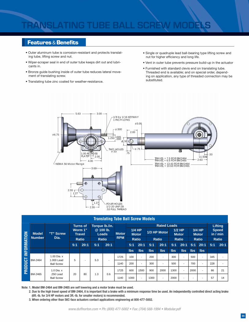
TRANSLATING TUBE BALL SCREW MODELS
• Outer aluminum tube is corrosion-resistant and protects translat-ing tube, lifting screw and nut.
• Wiper-scraper seal in end of outer tube keeps dirt out and lubri-cants in.
• Bronze guide bushing inside of outer tube reduces lateral move-ment of translating screw.
• Translating tube zinc coated for weather-resistance.
• Single or quadruple lead ball-bearing type lifting screw and nut for higher effi ciency and long life.
• Vent in outer tube prevents pressure build-up in the actuator
• Furnished with standard clevis end on translating tube. Threaded end is available; and on special order, depend-ing on application, any type of threaded connection may be substituted.
Translating Tube Ball Screw Models
PROD
UCT
INFO
RMAT
ION
5:1 20:1 5:1 20:1 5:1 20:1 5:1 20:1 5:1 20:1 5:1 20:1 5:1 20:1lbs lbs lbs lbs lbs lbslbs lbs
1725 100 - 200 - 300 - 500 - 345 -
1140 200 - 300 - 500 - 700 - 228 -
1725 600 1500 900 2000 1300 - 2000 - 86 21
1140 1000 - 1300 - 2000 - - - 57 14BM-2465
1.00 Dia. x1.000 LeadBall Screw
1.0 Dia. x.250 LeadBall Screw
5
20
Ratio
Rated Loads Lifting Speed
in / min
BM-2464 - 5.3 -
RatioModel
Number"T" Screw
Dia.
3/4 HP MotorRatio
Turns of Worm 1"
Travel
Torque lb./in. @ 100 lb.
Loads1/4 HP MotorRatio
Motor RPMRatio
80 1.3 0.6
1/2 HP MotorRatio
1/3 HP Motor
Ratio
Note: 1. Model BM-2464 and BM-2465 are self lowering and a motor brake must be used. 2. Due to the high travel speed of BM-2464, it is important that a brake with a minimum response time be used. An independently controlled direct acting brake (6ft.-lb. for 3/4 HP motors and 3ft.-lb. for smaller motors) is recommended. 3. When ordering other than 56C-face actuators contact applications engineering at 800-477-5002.
NEMA 56 Motor Flange
1/8 by 1/16 KEYWAY1 INCH LONG
5.63 3.00
4.00
2.00
.500
.005
ACROSSFLATS
6.75
1.00
.000+1.250 -
.53TWO HOLES
1.50
.75
.75
2.63
.53
TRAVEL + 13.43 FOR BM2464TRAVEL + 10.63 FOR BM2465
TRAVEL + 7.5 FOR BM2464TRAVEL + 6.5 FOR BM2465
2.00
3.00
1.500
FOUR HOLES1/2-20 UNF-2B.53 FULL THREAD
1.27
3.63
2.55
1.27
2.55
www.duffnorton.com • Ph: (800) 477-5002 • Fax: (704) 588-1994 • Modular.pdf
55
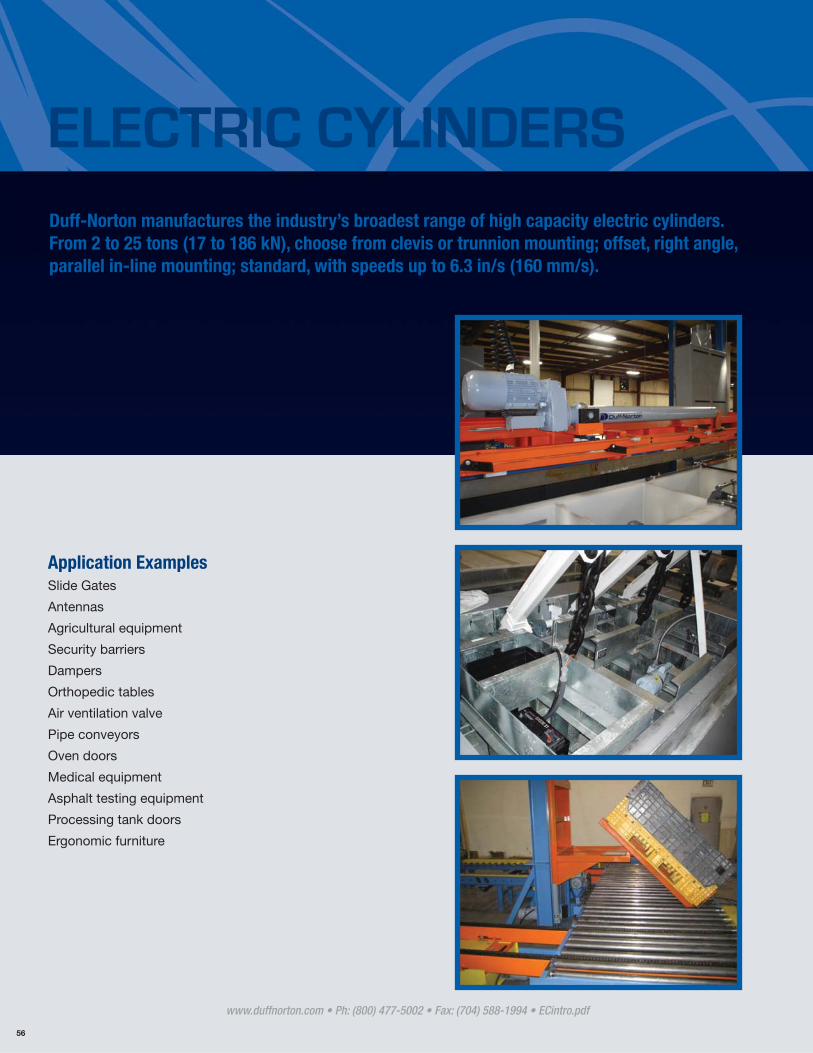
Application ExamplesSlide Gates
Antennas
Agricultural equipment
Security barriers
Dampers
Orthopedic tables
Air ventilation valve
Pipe conveyors
Oven doors
Medical equipment
Asphalt testing equipment
Processing tank doors
Ergonomic furniture
Duff-Norton manufactures the industry’s broadest range of high capacity electric cylinders. From 2 to 25 tons (17 to 186 kN), choose from clevis or trunnion mounting; offset, right angle, parallel in-line mounting; standard, with speeds up to 6.3 in/s (160 mm/s).
ELECTRIC CYLINDERS
www.duffnorton.com • Ph: (800) 477-5002 • Fax: (704) 588-1994 • ECintro.pdf
56
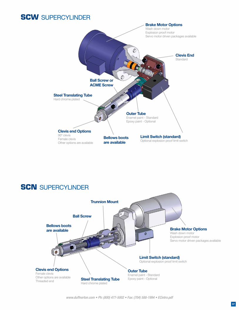
Outer TubeEnamel paint - StandardEpoxy paint - Optional
Ball Screw
Bellows boots are available
Clevis end OptionsFemale clevis Other options are availableThreaded end Steel Translating Tube
Hard chrome plated
Trunnion Mount
Brake Motor OptionsWash down motorExplosion proof motorServo motor driven packages available
Limit Switch (standard)Optional explosion proof limit switch
SCN SUPERCYLINDER
Outer TubeEnamel paint - StandardEpoxy paint - Optional
Ball Screw or ACME Screw
Bellows boots are available
Clevis end Options90º clevisFemale clevis Other options are available
Steel Translating TubeHard chrome plated
Brake Motor OptionsWash down motorExplosion proof motor Servo motor driven packages available
Limit Switch (standard)Optional explosion proof limit switch
Clevis EndStandard
SCW SUPERCYLINDER
www.duffnorton.com • Ph: (800) 477-5002 • Fax: (704) 588-1994 • ECintro.pdf
57
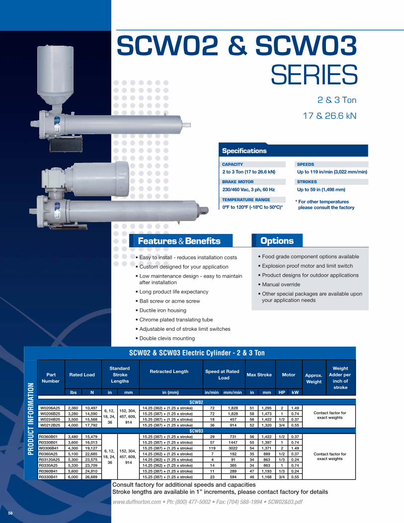
SCW02 & SCW03SERIES
2 & 3 Ton
17 & 26.6 kN
CAPACITY
BRAKE MOTOR
TEMPERATURE RANGE
SPEEDS
STROKES
Up to 119 in/min (3,022 mm/min)
Up to 59 in (1,498 mm)
2 to 3 Ton (17 to 26.6 kN)
230/460 Vac, 3 ph, 60 Hz
0ºF to 120ºF (-18ºC to 50ºC)*
Specifications
* For other temperatures please consult the factory
• Easy to install - reduces installation costs
• Custom designed for your application
• Low maintenance design - easy to maintain after installation
• Long product life expectancy
• Ball screw or acme screw
• Ductile iron housing
• Chrome plated translating tube
• Adjustable end of stroke limit switches
• Double clevis mounting
• Food grade component options available
• Explosion proof motor and limit switch
• Product designs for outdoor applications
• Manual override
• Other special packages are available upon your application needs
Options
www.duffnorton.com • Ph: (800) 477-5002 • Fax: (704) 588-1994 • SCW02&03.pdf
58
Retracted Length
lbs N in mm in (mm) in/min mm/min in mm HP kW
W0206A25 2,360 10,497 14.25 (362) + (1.25 x stroke) 72 1,828 51 1,295 2 1.49
W0206B25 3,280 14,590 15.25 (387) + (1.25 x stroke) 72 1,828 58 1,473 1 0.74
W0224B25 3,500 15,568 15.25 (387) + (1.25 x stroke) 18 457 56 1,422 1/2 0.37
W0212B25 4,000 17,792 15.25 (387) + (1.25 x stroke) 36 914 52 1,320 3/4 0.55
R0360B01 3,480 15,479 15.25 (387) + (1.25 x stroke) 29 731 56 1,422 1/2 0.37
R0330B01 3,600 16,013 15.25 (387) + (1.25 x stroke) 57 1447 55 1,397 1 0.74
W0306B41 4,300 19,127 15.25 (387) + (1.25 x stroke) 119 3022 54 1,371 2 1.49
R0360A25 5,100 22,685 14.25 (362) + (1.25 x stroke) 7 182 35 889 1/2 0.37
R03120A25 5,300 23,575 14.25 (362) + (1.25 x stroke) 4 91 34 863 1/3 0.24
R0330A25 5,330 23,709 14.25 (362) + (1.25 x stroke) 14 365 34 863 1 0.74
R0360B41 5,600 24,910 15.25 (387) + (1.25 x stroke) 11 289 47 1,193 1/3 0.24
R0330B41 6,000 26,689 15.25 (387) + (1.25 x stroke) 23 594 46 1,168 3/4 0.55
SCW02
SCW03
6, 12,
18, 24,
36
152, 304,
457, 609,
914
Speed at Rated Load
Max Stroke Motor Approx. Weight
Weight Adder per
inch of stroke
152, 304,
457, 609,
914
Rated LoadPart Number
Standard Stroke
Lengths
6, 12,
18, 24,
36
SCW02 & SCW03 Electric Cylinder - 2 & 3 Ton
PROD
UCT
INFO
RMAT
ION
Contact factor forexact weights
Contact factor forexact weights
Consult factory for additional speeds and capacitiesStroke lengths are available in 1” increments, please contact factory for details
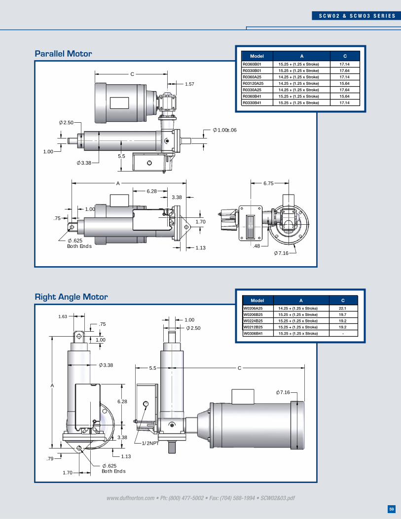
S C W 0 2 & S C W 0 3 S E R I E S
www.duffnorton.com • Ph: (800) 477-5002 • Fax: (704) 588-1994 • SCW02&03.pdf
59
.75
1.00
.625Both Ends
3.386.28
1.70
1.13
A
1.57
C
1.00±.06
5.51.00
2.50
3.38
6.75
7.16.48
1.00
.75
1.63
6.28
3.38
1.13
1.70
.79.625
Both Ends
3.38
A
1.00
2.50
5.5
7.16
C
1/2NPT
Model A C
W0206A25 14.25 + (1.25 x Stroke) 22.1
W0206B25 15.25 + (1.25 x Stroke) 19.7
W0224B25 15.25 + (1.25 x Stroke) 19.2
W0212B25 15.25 + (1.25 x Stroke) 19.2
W0306B41 15.25 + (1.25 x Stroke) -
Model A C
R0360B01 15.25 + (1.25 x Stroke) 17.14
R0330B01 15.25 + (1.25 x Stroke) 17.64
R0360A25 14.25 + (1.25 x Stroke) 17.14
R03120A25 14.25 + (1.25 x Stroke) 15.64
R0330A25 14.25 + (1.25 x Stroke) 17.64
R0360B41 15.25 + (1.25 x Stroke) 15.64
R0330B41 15.25 + (1.25 x Stroke) 17.14
Right Angle Motor
Parallel Motor
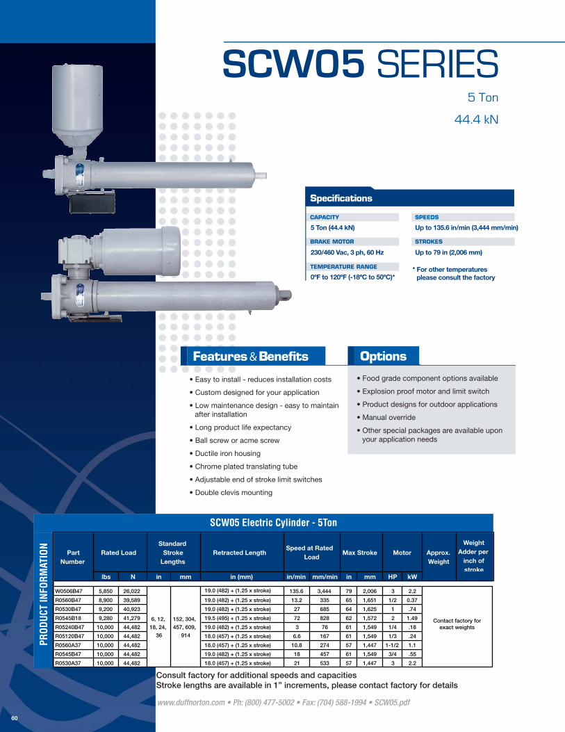
SCW05 SERIES5 Ton
44.4 kN
CAPACITY
BRAKE MOTOR
TEMPERATURE RANGE
SPEEDS
STROKES
Up to 135.6 in/min (3,444 mm/min)
Up to 79 in (2,006 mm)
5 Ton (44.4 kN)
230/460 Vac, 3 ph, 60 Hz
0ºF to 120ºF (-18ºC to 50ºC)*
Specifications
* For other temperatures please consult the factory
• Easy to install - reduces installation costs
• Custom designed for your application
• Low maintenance design - easy to maintain after installation
• Long product life expectancy
• Ball screw or acme screw
• Ductile iron housing
• Chrome plated translating tube
• Adjustable end of stroke limit switches
• Double clevis mounting
• Food grade component options available
• Explosion proof motor and limit switch
• Product designs for outdoor applications
• Manual override
• Other special packages are available upon your application needs
Options
www.duffnorton.com • Ph: (800) 477-5002 • Fax: (704) 588-1994 • SCW05.pdf
60
Retracted Length
lbs N in mm in (mm) in/min mm/min in mm HP kW
W0506B47 5,850 26,022 135.6 3,444 79 2,006 3 2.2
R0560B47 8,900 39,589 19.0 (482) + (1.25 x stroke) 13.2 335 65 1,651 1/2 0.37
R0530B47 9,200 40,923 19.0 (482) + (1.25 x stroke) 27 685 64 1,625 1 .74
R0545B18 9,280 41,279 19.5 (495) + (1.25 x stroke) 72 828 62 1,572 2 1.49
R05240B47 10,000 44,482 19.0 (482) + (1.25 x stroke) 3 76 61 1,549 1/4 .18
R05120B47 10,000 44,482 18.0 (457) + (1.25 x stroke) 6.6 167 61 1,549 1/3 .24
R0560A37 10,000 44,482 18.0 (457) + (1.25 x stroke) 10.8 274 57 1,447 1-1/2 1.1
R0545B47 10,000 44,482 19.0 (482) + (1.25 x stroke) 18 457 61 1,549 3/4 .55
R0530A37 10,000 44,482 18.0 (457) + (1.25 x stroke) 21 533 57 1,447 3 2.2
SCW05 Electric Cylinder - 5Ton
Rated Load
6, 12,
18, 24,
36
Standard Stroke
Lengths
Speed at Rated Load
Max Stroke Motor Approx. Weight
Weight Adder per
inch of stroke
Part Number
152, 304,
457, 609,
914
PROD
UCT
INFO
RMAT
ION
19.0 (482) + (1.25 x stroke)
Contact factory forexact weights
Consult factory for additional speeds and capacitiesStroke lengths are available in 1” increments, please contact factory for details

S C W 0 5 S E R I E S
www.duffnorton.com • Ph: (800) 477-5002 • Fax: (704) 588-1994 • SCW05.pdf
61
4.25
1.37
2.19
.79
.88
1.12
.750Both Ends
6.28A
1.97
7.16
2.36C
1.00 ±.06
6.28
1.00
3.004.13
6.25
1.00
3.00
4.13
6.3
1.00 ±.06
24.6
9.22
1.12
.882.00
.750Both Ends
1.37.79
2.19
4.25
6.28
(1.2
5 x
Stro
ke)
+ 1
9Model A C
R0560B47 19.0 + (1.25 x Stroke) 17.26
R0530B47 19.0 + (1.25 x Stroke) 17.76
R0545B18 19.5 + (1.25 x Stroke) 21.77
R05240B47 19.0 + (1.25 x Stroke) 15.76
R05120B47 19.0 + (1.25 x Stroke) 15.76
R0560A37 18.0 + (1.25 x Stroke) 19.61
R0545B47 19.0 + (1.25 x Stroke) 17.26
R0530A37 18.0 + (1.25 x Stroke) 21.77
Right Angle Motor
Parallel Motor
Model: W0506B47

SCW10 SERIES10 Ton
88.9 kN
CAPACITY
BRAKE MOTOR
TEMPERATURE RANGE
SPEEDS
STROKES
Up to 108 in/min (2,743 mm/min)
Up to 108 in (2,743 mm)
10 Ton (89.9 kN)
230/460 Vac, 3 ph, 60 Hz
0ºF to 120ºF (-18ºC to 50ºC)*
Specifications
* For other temperatures please consult the factory
• Easy to install - reduces installation costs
• Custom designed for your application
• Low maintenance design - easy to maintain after installation
• Long product life expectancy
• Ball screw or acme screw
• Ductile iron housing
• Chrome plated translating tube
• Adjustable end of stroke limit switches
• Double clevis mounting
• Food grade component options available
• Explosion proof motor and limit switch
• Product designs for outdoor applications
• Manual override
• Other special packages are available upon your application needs
Options
www.duffnorton.com • Ph: (800) 477-5002 • Fax: (704) 588-1994 • SCW10.pdf
62
Retracted Length
lbs N in mm in (mm) in/min mm/min in mm HP kW
W1012B50 9,600 42,702 72 1828 108 2,743 3 2.20
W1008B50 11,000 48,930 108 2743 108 2,743 5 3.70
R1060B50 15,500 68,947 22.125 (562) + (1.25 x stroke) 14.4 365 108 2,743 1 0.74
R1080A50 17,500 77,843 19.625 (498) + (1.25 x stroke) 10.8 274 73 1,854 2 1.49
R10160B50 18,900 84,071 22.125 (562) + (1.25 x stroke) 5.4 137 108 2,743 1/2 0.37
R10320A50 20,000 88,964 19.625 (498) + (1.25 x stroke) 2.7 68 69 1,752 3/4 0.55
R10160A50 20,000 88,964 19.625 (498) + (1.25 x stroke) 5.4 137 69 1,752 1-1/2 1.10
R1080B50 20,000 88,964 22.125 (562) + (1.25 x stroke) 10.8 274 108 2,743 1 0.74
R1040B50 20,000 88,964 22.125 (562) + (1.25 x stroke) 21.6 548 108 2,743 2 1.49
R1040A50 20,000 88,964 19.625 (498) + (1.25 x stroke) 21.6 548 69 1,752 5 3.70
SCW10 Electric Cylinder - 10 Ton
Rated LoadStandard
Stroke Lengths
6, 12,
18, 24,
36
Speed at Rated Load
Max Stroke
Motor Approx. Weight
Weight Adder per
inch of stroke
Contact factory forexact weights
Part Number
152, 304,
457, 609,
914
PROD
UCT
INFO
RMAT
ION
22.125 (562) + (1.25 x stroke)
22.125 (562) + (1.25 x stroke)
Consult factory for additional speeds and capacitiesStroke lengths are available in 1” increments, please contact factory for details
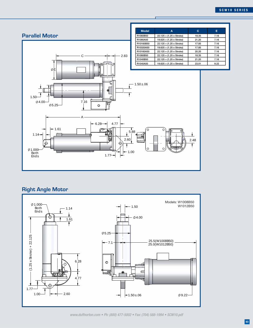
S C W 1 0 S E R I E S
www.duffnorton.com • Ph: (800) 477-5002 • Fax: (704) 588-1994 • SCW10.pdf
63
1.14
1.61
1.000BothEnds 1.77
2.60
5.88
4.776.28
A
1.00
2.83C
E
1.504.00
5.257.16
1.50 ±.06
2.48
1.50
1.50±.06
4.00
5.25
7.1
9.22
25.0(W1012B50)25.5(W1008B50)
1.14
1.61
1.000BothEnds
6.28
4.77
2.60
1.77
(1.2
5 x
Stro
ke)
+ 2
2.12
5
1.00
Model A C E
R1060B50 22.125 + (1.25 x Stroke) 18.35 7.16
R1080A50 19.625 + (1.25 x Stroke) 21.20 7.16
R10160B50 22.125 + (1.25 x Stroke) 17.85 7.16
R10320A50 19.625 + (1.25 x Stroke) 17.85 7.16
R10160A50 22.125 + (1.25 x Stroke) 20.20 7.16
R1080B50 22.125 + (1.25 x Stroke) 18.35 7.16
R1040B50 22.125 + (1.25 x Stroke) 21.20 7.16
R1040A50 19.625 + (1.25 x Stroke) 23.01 9.22
Right Angle Motor
Parallel Motor
Models: W1008B50 W1012B50

SCW20 SERIES20 Ton
177.9 kN
CAPACITY
BRAKE MOTOR
TEMPERATURE RANGE
SPEEDS
STROKES
Up to 21.6 in/min (2,743 mm/min)
Up to 132 in (3,352 mm)
20 Ton (177.9 kN)
230/460 Vac, 3 ph, 60 Hz
0ºF to 120ºF (-18ºC to 50ºC)*
Specifications
* For other temperatures please consult the factory
• Easy to install - reduces installation costs
• Custom designed for your application
• Low maintenance design - easy to maintain after installation
• Long product life expectancy
• Ball screw or acme screw
• Ductile iron housing
• Chrome plated translating tube
• Adjustable end of stroke limit switches
• Double clevis mounting
• Food grade component options available
• Explosion proof motor and limit switch
• Product designs for outdoor applications
• Manual override
• Other special packages are available upon your application needs
Options
www.duffnorton.com • Ph: (800) 477-5002 • Fax: (704) 588-1994 • SCW20.pdf
64

S C W 2 0 S E R I E S
www.duffnorton.com • Ph: (800) 477-5002 • Fax: (704) 588-1994 • SCW20.pdf
65
2.25
6.88
6.756.28
1.63
2.13
1.250BothEnds
A
2.60
1.25
3.39C
7.68
2.00
7.66
2.00 ±.06
4.88
E
2.95
Model A C E
R20160B50 26.25 + (1.25 x Stroke) 19.09 7.16
R2080B50 26.25 + (1.25 x Stroke) 20.97 7.16
R2060B50 26.25 + (1.25 x Stroke) 21.97 7.16
R2040B50 26.25 + (1.25 x Stroke) 23.07 9.22
R20320B50 26.25 + (1.25 x Stroke) 19.09 7.16
R20320A50 24.25 + (1.25 x Stroke) 20.97 7.16
R2080A50 24.25 + (1.25 x Stroke) 23.52 9.22
R20160A50 24.25 + (1.25 x Stroke) 23.07 9.22
Part Number
Retracted Length
lbs N in mm in (mm) in/min mm/min in mm HP kW
R20160B50 26,800 119,212 26.25 (666) + (1.25 x stroke) 5.4 137 132 3,352 3/4 0.55
R2080B50 29,300 130,332 26.25 (666) + (1.25 x stroke) 10.8 274 132 3,352 1-1/2 1.10
R2060B50 29,700 132,112 26.25 (666) + (1.25 x stroke) 14.4 365 132 3,352 2 1.49
R2040B50 30,700 136,560 26.25 (666) + (1.25 x stroke) 21.6 548 132 3,352 3 2.20
R20320B50 30,900 137,450 26.25 (666) + (1.25 x stroke) 2.7 68 132 3,352 1/2 0.37
R20320A50 32,000 142,343 24.25 (616) + (1.25 x stroke) 2.7 68 99 2,514 1-1/2 1.10
R2080A50 32,000 142,343 24.25 (616) + (1.25 x stroke) 10.8 274 99 2,514 5 3.70
R20160A50 35,000 155,687 24.25 (616) + (1.25 x stroke) 5.4 137 95 2,413 3 2.20
SCW20 Electric Cylinder
Rated LoadStandard
Stroke Lengths
6, 12,
18, 24,
36
Speed at Rated Load
Max Stroke
MotorApprox. Weight
Weight Adder
per inch of stroke
152, 304,
457, 609,
914
PROD
UCT
INFO
RMAT
ION
Contact factory forexact weights
Consult factory for additional speeds and capacitiesStroke lengths are available in 1” increments, please contact factory for details

SCW25 SERIES25 Ton
222 kN
CAPACITY
BRAKE MOTOR
TEMPERATURE RANGE
SPEEDS
STROKES
Up to 19.58 in/min (502 mm/min)
Up to 140 in (3,581 mm)
25 Ton (222 kN)
230/460 Vac, 3 ph, 60 Hz
0ºF to 120ºF (-18ºC to 50ºC)*
Specifications
* For other temperatures please consult the factory
• Easy to install - reduces installation costs
• Custom designed for your application
• Low maintenance design - easy to maintain after installation
• Long product life expectancy
• Ball screw or acme screw
• Ductile iron housing
• Chrome plated translating tube
• Adjustable end of stroke limit switches
• Double clevis mounting
• Food grade component options available
• Explosion proof motor and limit switch
• Product designs for outdoor applications
• Manual override
• Other special packages are available upon your application needs
Options
www.duffnorton.com • Ph: (800) 477-5002 • Fax: (704) 588-1994 • SCW25.pdf
66

S C W 2 5 S E R I E S
www.duffnorton.com • Ph: (800) 477-5002 • Fax: (704) 588-1994 • SCW25.pdf
67
1.88
2.63
5.88
1.500BothEnds
2.68
3.75
8.63
8.186.28A
1.50
7.252.50
5.88 10.4
E
8
3.5C
2.50±.09
2.68
Model A C E
R25150A66 29.12 + (1.25 x Stroke) 23.23 7.91
R2578B66 32.12 + (1.25 x Stroke) 22.24 7.91
R25104A66 29.12 + (1.25 x Stroke) 28.51 10.47
R25115B66 32.12 + (1.25 x Stroke) 20.43 7.20
R25334B66 32.12 + (1.25 x Stroke) 17.83 6.50
R25283A66
R25156B66 32.12 + (1.25 x Stroke) 20.43 7.20
R2556B66
29.12 + (1.25 x Stroke) - -
32.12 + (1.25 x Stroke) 20.43 7.20
Retracted Length
lbs N in mm in (mm) in/min mm/min in mm HP kW
R25150A66 47,400 210,845 29.12 (739) + (1.25 x stroke) 7.2 182 140 3,581 5 3.7
R2578B66 49,300 219,297 32.12 (815) + (1.25 x stroke) 14.4 365 130 3,327 3 2.2
R25104A66 49,500 220,186 29.12 (739) + (1.25 x stroke) 10.8 274 138 3,505
R25115B66 49,900 221,966 32.12 (815) + (1.25 x stroke) 9.6 243 130 3,302
7-1/2 5.5
R25334B66 50,000 222,411 32.12 (815) + (1.25 x stroke) 3 76 130 3,302 2 1.49
R25283A66 50,000 222,411 3.6 91 137 3,479 3/4 .55
R25156B66 50,000 222,411 32.12 (815) + (1.25 x stroke) 7.2 182 130 3,302 5 3.7
R2556B66 50,000 222,411 32.12 (815) + (1.25 x stroke) 19.8 502 130 3,302 5 3.7
SCW25 Electric Cylinder
Part Number
Rated LoadStandard
Stroke Lengths
6, 12,
18, 24,
36
Weight Adder
per inch of stroke
Speed at Rated Load
Max Stroke in
(mm)Motor Approx.
Weight
152, 304,
457, 609,
914
PROD
UCT
INFO
RMAT
ION
32.12 (815) + (1.25 x stroke)
2 1.49 Contact factory for exact weights
Consult factory for additional speeds and capacitiesStroke lengths are available in 1” increments, please contact factory for details

SCN03 SERIES3 Ton
26.6 kN
CAPACITY
BRAKE MOTOR
TEMPERATURE RANGE
SPEEDS
STROKES
Up to 182.4 in/min (4,633 mm/m
Up to 61 in (1,549 mm)
3 Ton (26.6 kN)
TEFC 230/460 Vac, 3 ph, 60 Hz
0ºF to 120ºF (-18ºC to 50ºC)*
Specifications
* For other temperatures please consult the factory
• Easy to install - reduces installation costs
• Custom designed for your application
• Low maintenance design - easy to maintain after installation
• Long product life expectancy
• Ball screw
• Ductile iron housing
• Chrome plated translating tube
• Adjustable end of stroke limit switches
• Clevis and trunnion mounting
• Motor confi guration include: parallel, right angle and off set
• Food grade component options available
• Product designs for outdoor applications
• Manual override
• Other special packages are available upon your application needs
Options
www.duffnorton.com • Ph: (800) 477-5002 • Fax: (704) 588-1994 • SCN03.pdf
68

S C N 0 3 S E R I E S
www.duffnorton.com • Ph: (800) 477-5002 • Fax: (704) 588-1994 • SCN03.pdf
69
.75
1.00
.625
(1.25 x Stroke) + 10.94
2.47
P
C
AB
3.248
1.000
FP
N
4.334.503.38
2.50
1.00
1.00 TB
Motor HP C FP AB TB N P
.16-.25 17.00 5.17 4.84 7.94 5.20 3.43
.33-.50 17.95 5.71 5.24 8.25 5.20 3.43
.75-1.0 19.05 6.50 5.63 8.21 6.02 4.25
Part Number
Retracted Length
lbs N in mm in (mm) in/min mm/min in mm HP kW
NZ03-0424 2,134 9,492 165.6 4,206 61 1,549 1 0.74
NZ03-0534 2,687 11,952 131.5 3,340 61 1,549 1 0.74
NZ03-1166 2,934 13,051 60.2 1,529 61 1,549 1/2 0.37
NZ03-0635 3,196 14,216 110.6 2,809 61 1,549 1 0.74
NZ03-0864 3,261 14,505 81.3 2,065 61 1,549 3/4 0.56
NZ03-0949 3,582 15,933 74.0 1,880 59 1,499 3/4 0.56
NZ03-0726 3,654 16,253 96.7 2,456 59 1,499 1 0.74
NZ03-2235 3,712 16,511 31.4 798 58 1,473 1/3 0.24
NZ03-1879 4,728 21,031 37.4 950 52 1,321 1/2 0.37
NZ03-4185 5,265 23,419 16.8 427 49 1,245 1/4 0.19
NZ03-8171 6,000 26,689 8.6 218 44 1,118 1/6 0.12
NZ03-5933 6,000 26,689 11.8 300 41 1,041 1/4 0.19
NZ03-3773 6,000 26,689 18.6 472 45 1,143 1/3 0.24
Rated LoadStandard
Stroke LengthsSpeed
Max Stroke
Motor Approx. Weight
Weight Adder
per inch of stroke
3 Ton Electric Cylinder (SCN) - Off Set Motor
6, 12,
18, 24,
36
152, 304,
457, 609,
914
10.94 (277) + (1.25 x stroke)
PROD
UCT
INFO
RMAT
ION
Contact factory forexact weights
Consult factory for additional speeds and capacitiesStroke lengths are available in 1” increments, please contact factory for details
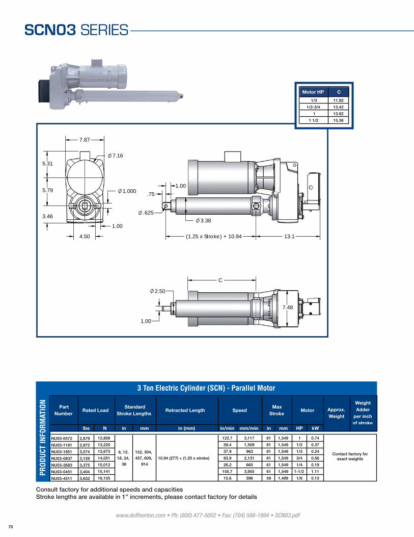
SCN03 SERIES
.75
1.00
.6253.38
(1.25 x Stroke) + 10.94 13.1
5.31
5.79
4.50
1.00
7.16
1.000
7.87
3.46
1.00
2.50
7.48
C
Motor HP C
1/3 11.92
1/2-3/4 13.42
1 13.92
1 1/2 15.36
www.duffnorton.com • Ph: (800) 477-5002 • Fax: (704) 588-1994 • SCN03.pdf
70
Part Number
Retracted Length
lbs N in mm in (mm) in/min mm/min in mm HP kW
NU03-0572 2,879 12,806 122.7 3,117 61 1,549 1 0.74
NU03-1181 2,972 13,220 59.4 1,509 61 1,549 1/2 0.37
NU03-1851 3,074 13,673 37.9 963 61 1,549 1/3 0.24
NU03-0837 3,159 14,051 83.9 2,131 61 1,549 3/4 0.56
NU03-2683 3,375 15,012 26.2 665 61 1,549 1/4 0.19
NU03-0451 3,404 15,141 155.7 3,955 61 1,549 1-1/2 1.11
NU03-4511 3,632 16,155 15.6 396 59 1,499 1/6 0.12
Max Stroke
MotorRated LoadStandard
Stroke Lengths
6, 12,
18, 24,
36
Speed Approx. Weight
Weight Adder
per inch of stroke
3 Ton Electric Cylinder (SCN) - Parallel Motor
152, 304,
457, 609,
914
10.94 (277) + (1.25 x stroke)
PROD
UCT
INFO
RMAT
ION
Contact factory forexact weights
Consult factory for additional speeds and capacitiesStroke lengths are available in 1” increments, please contact factory for details
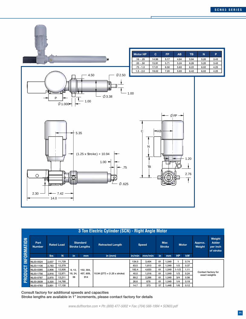
S C N 0 3 S E R I E S
5.35
2.30 7.4214.0
.75
1.00
.625
(1.25 x Stroke) + 10.94
FP
N
AB
1.20
2.76
TB
C
P
1.0001.00
4.50
3.381.00
2.50
Motor HP C FP AB TB N P
.16 - .25 14.96 5.17 4.84 5.94 5.20 3.43
.33 - .50 15.91 5.71 5.24 6.26 5.20 3.43
.75 - 1.0 17.01 6.50 5.63 6.22 6.02 4.25
1.5 - 2.0 19.02 7.20 5.83 6.42 6.02 4.25
www.duffnorton.com • Ph: (800) 477-5002 • Fax: (704) 588-1994 • SCN03.pdf
71
Part Number
Retracted Length
lbs N in mm in (mm) in/min mm/min in mm HP kW
NL03-0524 2,637 11,729 134.0 3,404 61 1,549 1 0.74
NL03-1106 2,783 12,379 63.5 1,613 61 1,549 1/2 0.37
NL03-0385 2,906 12,926 182.4 4,633 61 1,549 1-1/2 1.11
NL03-1756 2,916 12,971 40.0 1,016 61 1,549 1/3 0.24
NL03-0787 2,970 13,211 89.2 2,266 61 1,549 3/4 0.56
NL03-2639 3,320 14,768 26.6 676 61 1,549 1/4 0.19
NL03-4783 3,851 17,130 14.7 373 57 1,448 1/6 0.12
Approx. Weight
Weight Adder
per inch of stroke
3 Ton Electric Cylinder (SCN) - Right Angle Motor
Rated LoadStandard
Stroke LengthsSpeed
Max Stroke
Motor
152, 304,
457, 609,
914
10.94 (277) + (1.25 x stroke)
6, 12,
18, 24,
36
PROD
UCT
INFO
RMAT
ION
Contact factory forexact weights
Consult factory for additional speeds and capacitiesStroke lengths are available in 1” increments, please contact factory for details
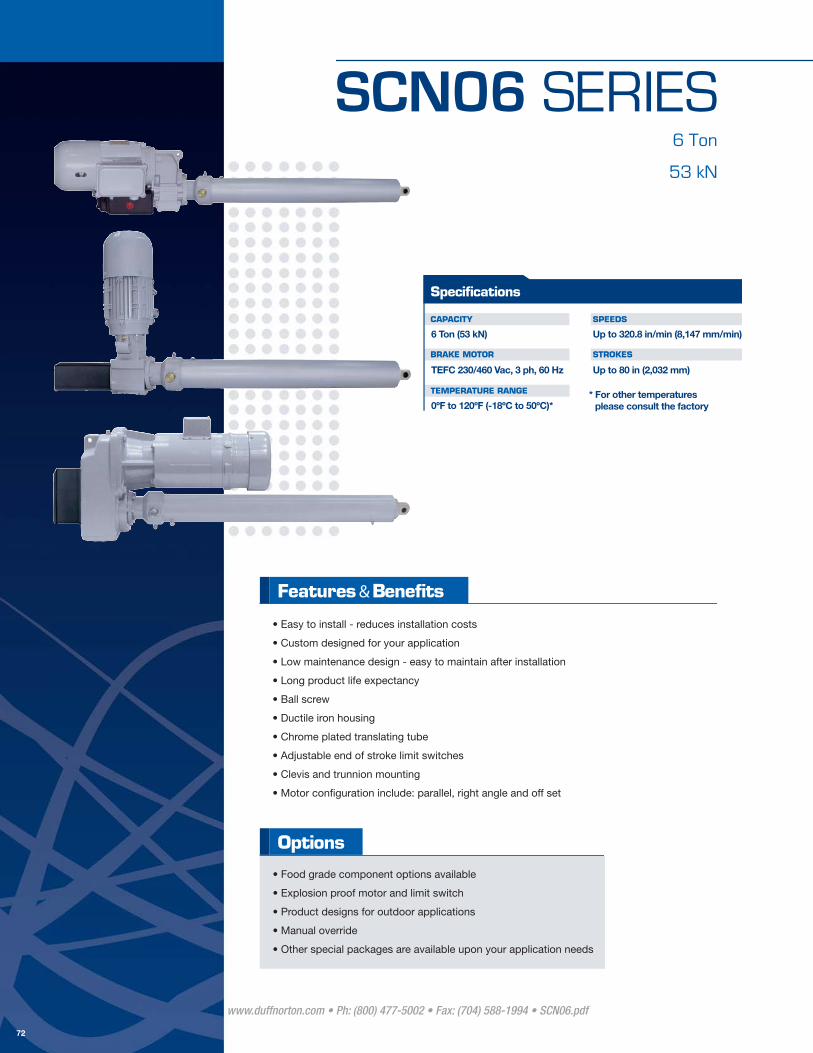
SCN06 SERIES6 Ton
53 kN
CAPACITY
BRAKE MOTOR
TEMPERATURE RANGE
SPEEDS
STROKES
Up to 320.8 in/min (8,147 mm/min)
Up to 80 in (2,032 mm)
6 Ton (53 kN)
TEFC 230/460 Vac, 3 ph, 60 Hz
0ºF to 120ºF (-18ºC to 50ºC)*
Specifications
* For other temperatures please consult the factory
• Easy to install - reduces installation costs
• Custom designed for your application
• Low maintenance design - easy to maintain after installation
• Long product life expectancy
• Ball screw
• Ductile iron housing
• Chrome plated translating tube
• Adjustable end of stroke limit switches
• Clevis and trunnion mounting
• Motor confi guration include: parallel, right angle and off set
• Food grade component options available
• Explosion proof motor and limit switch
• Product designs for outdoor applications
• Manual override
• Other special packages are available upon your application needs
Options
www.duffnorton.com • Ph: (800) 477-5002 • Fax: (704) 588-1994 • SCN06.pdf
72
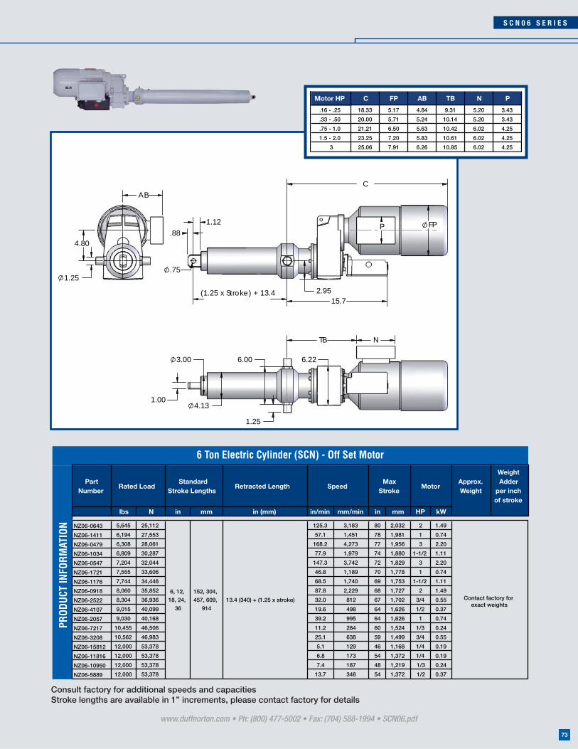
S C N 0 6 S E R I E S
www.duffnorton.com • Ph: (800) 477-5002 • Fax: (704) 588-1994 • SCN06.pdf
73
P FP
15.7
.881.12
.75
(1.25 x Stroke) + 13.4 2.95
N
1.00
3.00
4.13
6.00
1.25
TB
6.22
AB
4.80
1.25
C
Motor HP C FP AB TB N P
.16 - .25 18.33 5.17 4.84 9.31 5.20 3.43
.33 - .50 20.00 5.71 5.24 10.14 5.20 3.43
.75 - 1.0 21.21 6.50 5.63 10.42 6.02 4.25
1.5 - 2.0 23.25 7.20 5.83 10.61 6.02 4.25
3 25.06 7.91 6.26 10.85 6.02 4.25
Part Number
Retracted Length
lbs N in mm in (mm) in/min mm/min in mm HP kW
NZ06-0643 5,645 25,112 125.3 3,183 80 2,032 2 1.49
NZ06-1411 6,194 27,553 57.1 1,451 78 1,981 1 0.74
NZ06-0479 6,308 28,061 168.2 4,273 77 1,956 3 2.20
NZ06-1034 6,809 30,287 77.9 1,979 74 1,880 1-1/2 1.11
NZ06-0547 7,204 32,044 147.3 3,742 72 1,829 3 2.20
NZ06-1721 7,555 33,606 46.8 1,189 70 1,778 1 0.74
NZ06-1176 7,744 34,446 68.5 1,740 69 1,753 1-1/2 1.11
NZ06-0918 8,060 35,852 87.8 2,229 68 1,727 2 1.49
NZ06-2522 8,304 36,936 32.0 812 67 1,702 3/4 0.55
NZ06-4107 9,015 40,099 19.6 498 64 1,626 1/2 0.37
NZ06-2057 9,030 40,168 39.2 995 64 1,626 1 0.74
NZ06-7217 10,455 46,506 11.2 284 60 1,524 1/3 0.24
NZ06-3208 10,562 46,983 25.1 638 59 1,499 3/4 0.55
NZ06-15812 12,000 53,378 5.1 129 46 1,168 1/4 0.19
NZ06-11816 12,000 53,378 6.8 173 54 1,372 1/4 0.19
NZ06-10950 12,000 53,378 7.4 187 48 1,219 1/3 0.24
NZ06-5889 12,000 53,378 13.7 348 54 1,372 1/2 0.37
Max Stroke
MotorApprox. Weight
Weight Adder
per inch of stroke
Rated LoadStandard
Stroke LengthsSpeed
6, 12,
18, 24,
36
152, 304,
457, 609,
914
13.4 (340) + (1.25 x stroke)
6 Ton Electric Cylinder (SCN) - Off Set Motor
PROD
UCT
INFO
RMAT
ION
Contact factory for exact weights
Consult factory for additional speeds and capacitiesStroke lengths are available in 1” increments, please contact factory for details
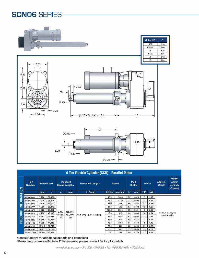
SCN06 SERIES
15(1.25 x Stroke) + 13.4
.88
1.12
.75
5.31
7.01
6.001.25
7.87
4.13
1.25
C
1.00
3.00
4.13
8.90
Motor HP C
1/3 11.16
1/2 3/4 12.66
1 13.16
1 1/2 14.16
2 15.16
3 16.04
www.duffnorton.com • Ph: (800) 477-5002 • Fax: (704) 588-1994 • SCN06.pdf
74
Part Number
Retracted Length
lbs N in mm in (mm) in/min mm/min in mm HP kW
NU06-0831 7,296 32,454 97.0 2,463 72 1,829 2 1.49
NU06-1667 7,318 32,552 48.3 1,228 71 1,803 1 0.74
NU06-2371 7,806 34,722 34.0 863 69 1,753 3/4 0.55
NU06-3777 8,290 36,875 21.3 542 67 1,702 1/2 0.37
NU06-0670 8,823 39,251 120.3 3,055 65 1,651 3 2.20
NU06-6412 9,288 40,319 12.6 319 63 1,600 1/3 0.24
NU06-1411 9,291 41,328 57.1 1,451 63 1,600 1-1/2 1.11
NU06-2245 9,855 43,837 35.9 912 62 1,575 1 0.74
NU06-1138 9,992 44,446 70.8 1,798 61 1,549 2 1.49
NU06-3193 10,513 46,764 25.2 641 60 1,524 3/4 0.55
NU06-5297 11,627 51,719 15.2 386 57 1,448 1/2 0.37
NU06-11223 12,000 53,378 7.2 182 48 1,219 1/3 0.24
6 Ton Electric Cylinder (SCN) - Parallel Motor
Rated LoadStandard
Stroke LengthsSpeed
Max Stroke
MotorApprox. Weight
Weight Adder
per inch of stroke
6, 12,
18, 24,
36
152, 304,
457, 609,
914
13.4 (340) + (1.25 x stroke)
PROD
UCT
INFO
RMAT
ION
Contact factory for exact weights
Consult factory for additional speeds and capacitiesStroke lengths are available in 1” increments, please contact factory for details

S C N 0 6 S E R I E S
7.58
P
.88
1.12
113.07
18(1.25 x Stroke) + 13.4
1.00
3.00
4.13
6.00
1.250
1.25
FP
AB
1.83
N
TB
3.07
C
Motor HP C FP AB TB N P
.16 - .25 15.79 5.17 4.84 6.47 5.20 3.43
.33 - .50 16.73 5.71 5.24 7.30 5.20 3.43
.75 - 1.0 17.83 6.50 5.63 7.58 6.02 4.25
1.5 - 2.0 20.43 7.20 5.83 7.77 6.02 4.25
3.0 - 5.0 22.24 7.91 6.26 8.01 6.02 4.25
www.duffnorton.com • Ph: (800) 477-5002 • Fax: (704) 588-1994 • SCN06.pdf
75
Part Number
Retracted Length
lbs N in mm in (mm) in/min mm/min in mm HP kW
NLH6-0530 3,280 14,594 320.8 8147.0 80 2,032 3 2.20
NLH6-0947 3,907 17,383 179.5 4560.0 80 2,032 2 1.49
NL06-0829 7,278 32,376 97.2 2469.0 72 1,829 2 1.49
NL06-1706 7,489 33,312 47.2 1200.0 71 1,803 1 0.74
NL06-1139 7,500 33,362 70.7 1797.0 71 1,803 1-1/2 1.11
NL06-2433 8,011 35,632 33.1 841.0 68 1,727 3/4 0.55
NL06-3862 8,477 37,707 20.9 530.0 68 1,676 1/2 0.37
NL06-6285 9,105 40,500 12.8 326.0 64 1,626 1/3 0.24
NL06-1084 9,517 42,335 74.3 1888.0 63 1,600 2 1.49
NL06-0732 9,640 42,882 110.1 2796.0 62 1,575 3 2.20
NL06-3380 11,129 49,502 23.8 606.0 58 1,473 3/4 0.55
NL06-5500 12,000 53,378 14.7 372.0 56 1,422 1/2 0.37
6, 12,
18, 24,
36
152, 304,
457, 609,
914
13.4 (340) + (1.25 x stroke)
6 Ton Electric Cylinder (SCN) - Right Angle Motor
Rated LoadStandard
Stroke LengthsSpeed
Max Stroke
MotorApprox. Weight
Weight Adder
per inch of stroke
PROD
UCT
INFO
RMAT
ION
Contact factory for exact weights
Consult factory for additional speeds and capacitiesStroke lengths are available in 1” increments, please contact factory for details

SCN12 SERIES12 Ton
106.7 kN
CAPACITY
BRAKE MOTOR
TEMPERATURE RANGE
SPEEDS
STROKES
Up to 188.5 in/min (4,787 mm/min)
Up to 110 in (2,794 mm)
12 Ton (106.7 kN)
TEFC 230/460 Vac, 3 ph, 60 Hz
0ºF to 120ºF (-18ºC to 50ºC)*
Specifications
* For other temperatures please consult the factory
• Easy to install - reduces installation costs
• Custom designed for your application
• Low maintenance design - easy to maintain after installation
• Long product life expectancy
• Ball screw
• Ductile iron housing
• Chrome plated translating tube
• Adjustable end of stroke limit switches
• Clevis and trunnion mounting
• Motor confi guration include: parallel, right angle and off set
• Food grade component options available
• Explosion proof motor and limit switch
• Product designs for outdoor applications
• Manual override
• Other special packages are available upon your application needs
Options
www.duffnorton.com • Ph: (800) 477-5002 • Fax: (704) 588-1994 • SCN12.pdf
76

S C N 1 2 S E R I E S
FP
PTB
1.14
1.61
1.000
17.4C(1.25 x Stroke) + 16.75
1.50
4.00
5.25
7.501.63 N
5.79
AB
1.7503.46
3.94
Motor HP C FP AB TB N P
.33 - .50 25.84 5.71 5.24 11.62 5.20 3.43
.75 - 1.0 25.92 6.50 5.63 11.70 6.02 4.25
1.5 - 2.0 26.11 7.20 5.85 11.90 6.02 4.25
3.0 - 5.0 26.35 7.91 6.26 12.13 6.02 4.25
Part Number
Retracted Length
lbs N in mm in (mm) in/min mm/min in mm HP kW
NZ12-0451 9,305 41,390 188.5 4,787 110 2,794 5 3.72
NZ12-1181 14,620 65,031 72.0 1,828 110 2,794 3 2.23
NZ12-1851 15,277 67,950 45.9 1,116 110 2,794 2 1.49
NZ12-3718 15,343 68,244 22.9 581 110 2,794 1 0.74
NZ12-2683 16,607 73,869 31.7 805 110 2,794 1-1/2 1.12
NZ12-1653 20,464 91,022 51.4 1,306 102 2,591 3 2.23
NZ12-2497 20,608 91,664 34.0 865 102 2,591 2 1.49
NZ12-1015 20,942 93,151 83.7 2,127 101 2,565 5 3.72
NZ12-3654 22,618 100,603 23.3 591 97 2,464 1-1/2 1.12
NZ12-27627 24,000 106,752 3.1 78 85 2,159 1/4 0.19
NZ12-23611 24,000 106,752 3.6 91 80 2,032 1/3 0.25
NZ12-18511 24,000 106,752 4.6 117 91 2,311 1/3 0.25
NZ12-14996 24,000 106,752 5.7 144 82 2,083 1/2 0.37
NZ12-12751 24,000 106,752 6.7 169 89 2,261 1/2 0.37
NZ12-10407 24,000 106,752 8.2 207 80 2,032 3/4 0.56
NZ12-8242 24,000 106,752 10.3 262 91 2,311 3/4 0.56
NZ12-6967 24,000 106,752 12.2 310 85 2,159 1 0.74
12 Ton Electric Cylinder (SCN) - Off Set Motor
Rated LoadStandard
Stroke LengthsSpeed
Max Stroke
Motor Approx. Weight
Weight Adder
per inch of stroke
6, 12,
18, 24,
36
152, 304,
457, 609,
914
16.75 (425) + (1.25 x
stroke)
PROD
UCT
INFO
RMAT
ION
Contact factory for exact weights
www.duffnorton.com • Ph: (800) 477-5002 • Fax: (704) 588-1994 • SCN12.pdf
77
Consult factory for additional speeds and capacitiesStroke lengths are available in 1” increments, please contact factory for details
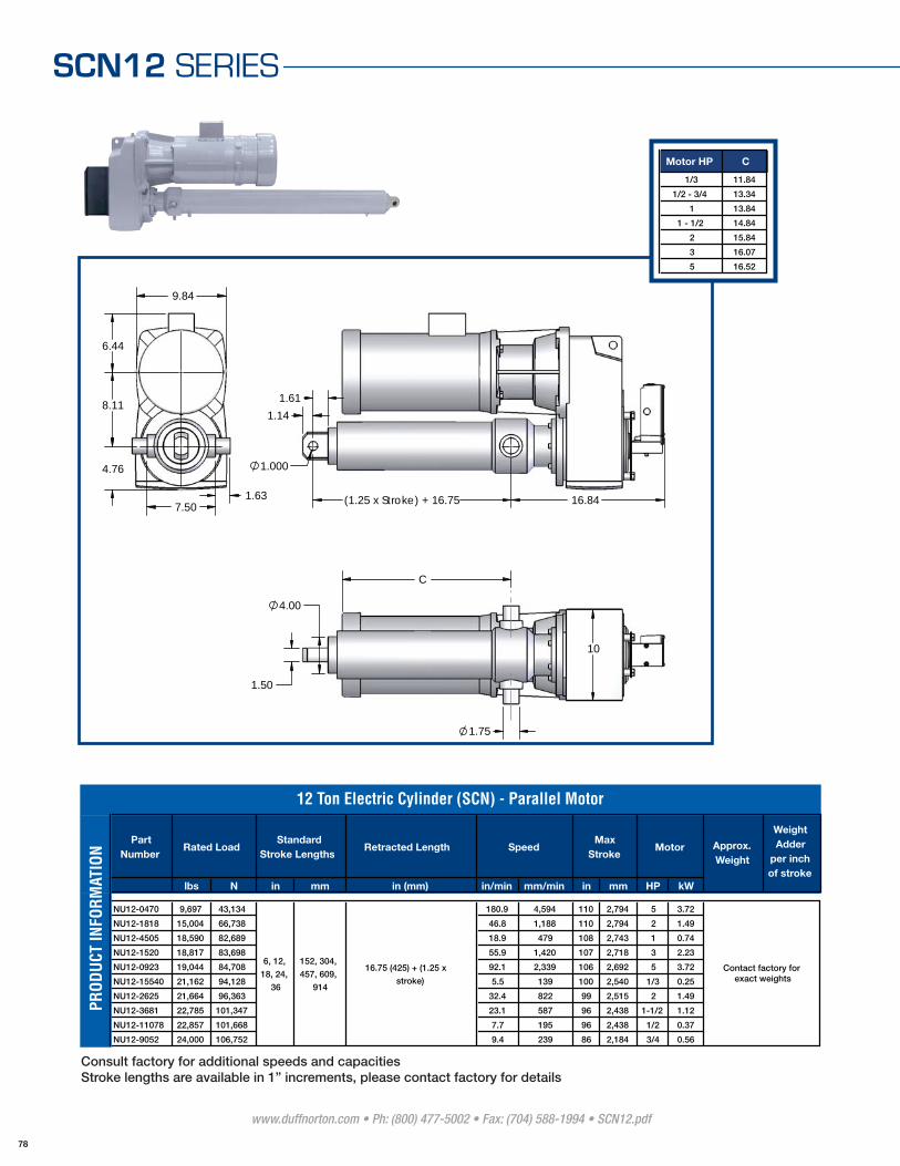
www.duffnorton.com • Ph: (800) 477-5002 • Fax: (704) 588-1994 • SCN12.pdf
78
SCN12 SERIES
1.61
1.14
1.000
16.84(1.25 x Stroke) + 16.75
6.44
8.11
7.501.63
4.76
9.84
10
1.50
4.00
1.75
C
Motor HP C
1/3 11.84
1/2 - 3/4 13.34
1 13.84
1 - 1/2 14.84
2 15.84
3 16.07
5 16.52
Part Number
Retracted Length
lbs N in mm in (mm) in/min mm/min in mm HP kW
NU12-0470 9,697 43,134 180.9 4,594 110 2,794 5 3.72
NU12-1818 15,004 66,738 46.8 1,188 110 2,794 2 1.49
NU12-4505 18,590 82,689 18.9 479 108 2,743 1 0.74
NU12-1520 18,817 83,698 55.9 1,420 107 2,718 3 2.23
NU12-0923 19,044 84,708 92.1 2,339 106 2,692 5 3.72
NU12-15540 21,162 94,128 5.5 139 100 2,540 1/3 0.25
NU12-2625 21,664 96,363 32.4 822 99 2,515 2 1.49
NU12-3681 22,785 101,347 23.1 587 96 2,438 1-1/2 1.12
NU12-11078 22,857 101,668 7.7 195 96 2,438 1/2 0.37
NU12-9052 24,000 106,752 9.4 239 86 2,184 3/4 0.56
6, 12,
18, 24,
36
152, 304,
457, 609,
914
16.75 (425) + (1.25 x
stroke)
Approx. Weight
Weight Adder
per inch of stroke
12 Ton Electric Cylinder (SCN) - Parallel Motor
Rated LoadStandard
Stroke LengthsSpeed
Max Stroke
Motor
PROD
UCT
INFO
RMAT
ION
Contact factory for exact weights
Consult factory for additional speeds and capacitiesStroke lengths are available in 1” increments, please contact factory for details
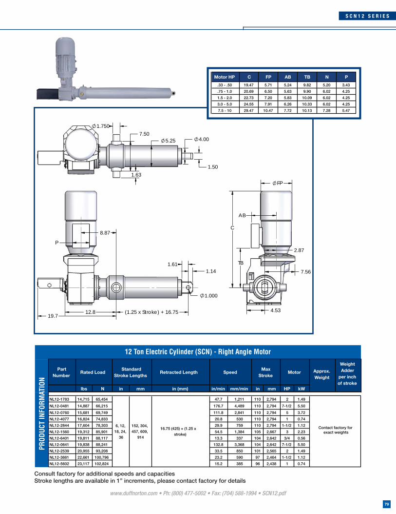
www.duffnorton.com • Ph: (800) 477-5002 • Fax: (704) 588-1994 • SCN12.pdf
79
S C N 1 2 S E R I E S
8.87
P
1.611.14
1.000
(1.25 x Stroke) + 16.7512.819.7
1.50
4.007.50
5.25
1.750
1.63
FP
AB
2.87
7.56
TB
4.53
C
Motor HP C FP AB TB N P
.33 - .50 19.47 5.71 5.24 9.82 5.20 3.43
.75 - 1.0 20.69 6.50 5.63 9.90 6.02 4.25
1.5 - 2.0 22.73 7.20 5.83 10.09 6.02 4.25
3.0 - 5.0 24.55 7.91 6.26 10.33 6.02 4.25
7.5 - 10 29.47 10.47 7.72 10.13 7.28 5.47
Part Number
Retracted Length
lbs N in mm in (mm) in/min mm/min in mm HP kW
NL12-1783 14,715 65,454 47.7 1,211 110 2,794 2 1.49
NL12-0481 14,887 66,215 176.7 4,489 110 2,794 7-1/2 5.50
NL12-0760 15,681 69,749 111.8 2,841 110 2,794 5 3.72
NL12-4077 16,824 74,833 20.8 530 110 2,794 1 0.74
NL12-2844 17,604 78,303 29.9 759 110 2,794 1-1/2 1.12
NL12-1560 19,312 85,901 54.5 1,384 105 2,667 3 2.23
NL12-6401 19,811 88,117 13.3 337 104 2,642 3/4 0.56
NL12-0641 19,838 88,241 132.8 3,368 104 2,642 7-1/2 5.50
NL12-2539 20,955 93,208 33.5 850 101 2,565 2 1.49
NL12-3661 22,661 100,796 23.2 590 97 2,464 1-1/2 1.12
NL12-5602 23,117 102,824 15.2 385 96 2,438 1 0.74
Max Stroke
Motor Approx. Weight
Weight Adder
per inch of stroke
Rated LoadStandard
Stroke LengthsSpeed
6, 12,
18, 24,
36
152, 304,
457, 609,
914
16.75 (425) + (1.25 x
stroke)
12 Ton Electric Cylinder (SCN) - Right Angle Motor
PROD
UCT
INFO
RMAT
ION
Contact factory for exact weights
Consult factory for additional speeds and capacitiesStroke lengths are available in 1” increments, please contact factory for details

www.duffnorton.com • Ph: (800) 477-5002 • Fax: (704) 588-1994 • SCN25.pdf
80
SCN25 SERIES25 Ton
222 kN
CAPACITY
BRAKE MOTOR
TEMPERATURE RANGE
SPEEDS
STROKES
Up to 259.7 in/min (6,596 mm/min)
Up to 161 in (4,089 mm)
25 Ton (222 kN)
TEFC 230/460 Vac, 3 ph, 60 Hz
0ºF to 120ºF (-18ºC to 50ºC)*
Specifications
* For other temperatures please consult the factory
• Easy to install - reduces installation costs
• Custom designed for your application
• Low maintenance design - easy to maintain after installation
• Long product life expectancy
• Ball screw
• Ductile iron housing
• Chrome plated translating tube
• Adjustable end of stroke limit switches
• Clevis and trunnion mounting
• Motor confi guration include: parallel, right angle and off set
• Food grade component options available
• Explosion proof motor and limit switch
• Product designs for outdoor applications
• Manual override
• Other special packages are available upon your application needs
Options
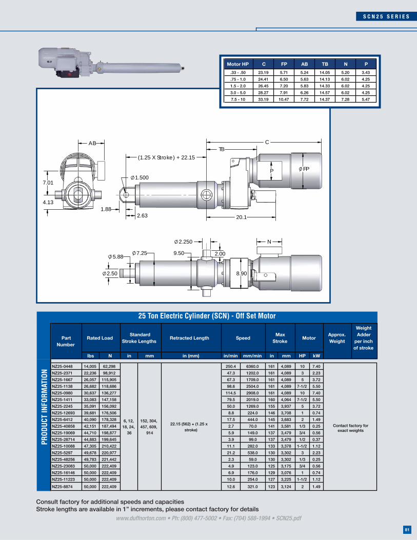
www.duffnorton.com • Ph: (800) 477-5002 • Fax: (704) 588-1994 • SCN25.pdf
81
S C N 2 5 S E R I E S
1.882.63
1.500
(1.25 X Stroke) + 22.15
TBC
20.1
P FP
7.01
AB
4.13
2.50
5.887.25 9.50
2.250
2.00
8.90
N
Motor HP C FP AB TB N P
.33 - .50 23.19 5.71 5.24 14.05 5.20 3.43
.75 - 1.0 24.41 6.50 5.63 14.13 6.02 4.25
1.5 - 2.0 26.45 7.20 5.83 14.33 6.02 4.25
3.0 - 5.0 28.27 7.91 6.26 14.57 6.02 4.25
7.5 - 10 33.19 10.47 7.72 14.37 7.28 5.47
Retracted Length
lbs N in mm in (mm) in/min mm/min in mm HP kW
NZ25-0448 14,005 62,298 250.4 6360.0 161 4,089 10 7.40
NZ25-2371 22,236 98,912 47.3 1202.0 161 4,089 3 2.23
NZ25-1667 26,057 115,905 67.3 1709.0 161 4,089 5 3.72
NZ25-1138 26,682 118,686 98.6 2504.0 161 4,089 7-1/2 5.50
NZ25-0980 30,637 136,277 114.5 2908.0 161 4,089 10 7.40
NZ25-1411 33,083 147,158 79.5 2019.0 160 4,064 7-1/2 5.50
NZ25-2245 35,091 156,092 50.0 1269.0 155 3,937 5 3.72
NZ25-12693 39,681 176,506 8.8 224.0 146 3,708 1 0.74
NZ25-6412 40,090 178,328 17.5 444.0 145 3,683 2 1.49
NZ25-40858 42,151 187,494 2.7 70.0 141 3,581 1/3 0.25
NZ25-19069 44,710 198,877 5.9 149.0 137 3,479 3/4 0.56
NZ25-28714 44,883 199,645 3.9 99.0 137 3,479 1/2 0.37
NZ25-10088 47,305 210,422 11.1 282.0 133 3,378 1-1/2 1.12
NZ25-5297 49,678 220,977 21.2 538.0 130 3,302 3 2.23
NZ25-48256 49,783 221,442 2.3 59.0 130 3,302 1/3 0.25
NZ25-23083 50,000 222,409 4.9 123.0 125 3,175 3/4 0.56
NZ25-16146 50,000 222,409 6.9 176.0 129 3,076 1 0.74
NZ25-11223 50,000 222,409 10.0 254.0 127 3,225 1-1/2 1.12
NZ25-8874 50,000 222,409 12.6 321.0 123 3,124 2 1.49
Approx. Weight
Weight Adder
per inch of stroke
25 Ton Electric Cylinder (SCN) - Off Set Motor
Rated LoadStandard
Stroke LengthsSpeed
Max Stroke
Motor
6, 12,
18, 24,
36
152, 304,
457, 609,
914
22.15 (562) + (1.25 x
stroke)
Part Number
PROD
UCT
INFO
RMAT
ION
Contact factory forexact weights
Consult factory for additional speeds and capacitiesStroke lengths are available in 1” increments, please contact factory for details

www.duffnorton.com • Ph: (800) 477-5002 • Fax: (704) 588-1994 • SCN25.pdf
82
SCN25 SERIES
2.63
1.88
1.500
19.1(1.25 x Stroke) + 22.15
7.59
9.88
9.502.00
10.81
5.75
2.50
5.88
7.25
12
2.250
C
Motor HP C
1/2 - 3/4 14.12
1 14.62
1 - 1/2 15.80
2 16.80
3 16.86
5 17.31
7.5 22.79
10 25.49
Retracted Length
lbs N in mm in (mm) in/min mm/min in mm HP kW
NU25-0432 13,505 60,073 259.7 6596.0 161 4,089 10 7.40
NU25-3050 28,605 127,238 36.8 934.0 161 4,089 3 2.23
NU25-2036 31,824 141,561 55.1 1400.0 161 4,089 5 3.72
NU25-1538 36,060 160,403 73.0 1853.0 153 3,886 7-1/2 5.50
NU25-1300 40,640 180,775 86.3 2192.0 144 3,657 10 7.40
NU25-13403 41,900 186,379 8.4 213.0 142 3,606 1 0.74
NU25-1888 44,267 196,906 59.4 1509.0 138 3,505 7-1/2 5.50
NU25-10019 46,982 208,983 11.2 284.0 134 3,403 1-1/2 1.12
NU25-8161 50,000 222,409 13.7 349.0 129 3,276 2 1.49
NU25-5555 50,000 222,409 20.2 513.0 127 3,225 3 2.23
Rated Load Approx. Weight
Weight Adder
per inch of stroke
25 Ton Electric Cylinder (SCN) - Parallel Motor
Standard Stroke Lengths
SpeedMax
StrokeMotor
6, 12,
18, 24,
36
152, 304,
457, 609,
914
22.15 (562) + (1.25 x
stroke)
Part Number
PROD
UCT
INFO
RMAT
ION
Contact factory forexact weights
Consult factory for additional speeds and capacitiesStroke lengths are available in 1” increments, please contact factory for details
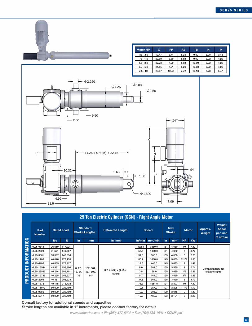
www.duffnorton.com • Ph: (800) 477-5002 • Fax: (704) 588-1994 • SCN25.pdf
83
S C N 2 5 S E R I E S
2.631.88
1.500
21.6
10.32
(1.25 x Stroke) + 22.15P
4.927.09
.94
FP
N
TB
C
2.50
5.88
9.502.00
2.250
7.25
Motor HP C FP AB TB N P
.33 - .50 19.47 5.71 5.24 9.82 5.20 3.43
.75 - 1.0 20.69 6.50 5.63 9.90 6.02 4.25
1.5 - 2.0 22.73 7.20 5.83 10.09 6.02 4.25
3.0 - 5.0 24.55 7.91 6.26 10.33 6.02 4.25
7.5 - 10 29.47 10.47 7.72 10.13 7.28 5.47
Retracted Length
lbs N in mm in (mm) in/min mm/min in mm HP kW
NL25-0848 26,510 117,921 132.3 3360.0 161 4,089 10 7.40
NL25-2023 31,621 140,657 55.5 1409.0 161 4,089 5 3.72
NL25-3561 33,397 148,556 31.5 800.0 159 4,038 3 2.23
NL25-1708 40,046 178,133 65.7 1668.0 145 3,683 7-1/2 5.50
NL25-6408 40,065 178,217 17.5 445.0 145 3,683 2 1.49
NL25-13944 43,591 193,900 8.0 204.0 139 3,530 1 0.74
NL25-29585 46,244 205,701 3.8 96.0 135 3,429 1/2 0.37
NL25-19745 46,295 205,927 5.7 144.0 135 3,429 3/4 0.56
NL25-2966 46,361 206,223 37.8 961.0 135 3,429 5 3.72
Weight Adder
per inch of stroke
25 Ton Electric Cylinder (SCN) - Right Angle Motor
Max Stroke
Motor Approx. Weight
Rated LoadStandard
Stroke LengthsSpeed
6, 12,
18, 24,
36
152, 304,
457, 609,
914
22.15 (562) + (1.25 x
stroke)
Part Number
PROD
UCT
INFO
RMAT
ION
Contact factory forexact weights
NL25-1573 49,175 218,738 71.3 1811.0 131 3,327 10 7.40
NL25-11077 50,000 222,409 10.1 257.0 127 3,225 1-1/2 1.12
NL25-9350 50,000 222,409 12.0 305.0 120 3,048 2 1.49
NL25-5917 50,000 222,409 19.0 482.0 123 3,124 3 2.23
Consult factory for additional speeds and capacitiesStroke lengths are available in 1” increments, please contact factory for details

www.duffnorton.com • Ph: (800) 477-5002 • Fax: (704) 588-1994 • installinfo.pdf
84
INSTALLATION INFORMATION
Duff-Norton Linear Actuators can be used in tension, compression, or combination tension/compression applications. Examples of tension and compression are shown below:
Loading
It is important to mount the actuator so that side loading and eccentric
loading are avoided. A clevis mount actuator should always be free to pivot
on its clevis pins. No brackets or supports should be used that restrain the
actuator housing or outer tube. To optimize the performance and life of the
actuator, it should be mounted so that the load is applied along the longitu-
dinal axis of the translating tube. Examples of proper and improper loading
arrangements are shown to the side.
Tension Compression
Side Loading Eccentric Loading
Compression Example: Access Door
Tension Example: Styrofoam Manipulator
Tension & Compression Example:Valve opening and closing
! WARNING
The equipment shown in this catalog is intended for industrial use only and should not be used to lift, support, or otherwise transport people unless you have written statement from Duff-Norton, which authorizes the specifi c ac-tuator used in your applications as suitable for moving people.

www.duffnorton.com • Ph: (800) 477-5002 • Fax: (704) 588-1994 • terms.pdf
85
TERMS OF SALEAll sales by Seller are made pursuant to the following terms. No other or additional terms or conditions are or will be accepted.
ACCEPTANCE OF ORDERS - All orders, whether placed directly or through an agent, and all subsequent amendments thereto, are subject to a final approval and acceptance by Seller’s main office.
LIMITATION OF WARRANTIES, REMEDIES AND DAMAGES – THE WARRANTY STATED BELOW IS GIVEN IN PLACE OF ALL OTHER WARRANTIES, EXPRESS OR IMPLIED, OF MERCHANTABILITY, FITNESS FOR A PARTICULAR PURPOSE OR OTHERWISE. NO PROMISE OR AFFIRMATION OF FACT MADE BY ANY AGENT OR REPRESENTATIVE OF SELLER SHALL CONSTITUTE A WARRANTY BY SELLER OR GIVE RISE TO ANY LIABILITY OR OBLIGATION. Seller warrants that on the date of its delivery to carrier the goods are free from defects in workmanship and materials. SELLER’S SOLE OBLIGATION IN THE EVENT OF BREACH OF WARRANTY OR CONTRACT OR FOR NEGLIGENCE OR OTHERWISE WITH RESPECT TO GOODS SOLD SHALL BE EXCLUSIVELY LIMITED TO REPAIR OR REPLACEMENT, F.O.B. SELLER’S POINT OF SHIPMENT, OF ANY PARTS WHICH SELLER DETERMINES TO HAVE BEEN DEFECTIVE or if Seller determines that such repair or replacement is not feasible, to a refund of the purchase price upon return of the goods to Seller. Any action against Seller for breach of warranty, negligence or otherwise must be commenced within one year after such cause of action accrues. NO CLAIM AGAINST SELLER FOR ANY DEFECT IN THE GOODS SHALL BE VALID OR ENFORCEABLE UNLESS BUYER’S WRITTEN NOTICE THEREOF IS RECEIVED BY SELLER WITHIN ONE YEAR FROM THE DATE OF SHIPMENT. Seller shall not be liable for any damage, injury or loss arising out of the use of the goods if, prior to such damage, injury or loss, such goods are (1) damaged or misused following Seller’s delivery to carrier; (2) not maintained, inspected, or used in compliance with applicable law and Seller’s written instructions and recommendations; or (3) installed, repaired, altered or modified without compliance with such law, instructions or recommendations. UNDER NO CIRCUMSTANCES SHALL SELLER BE LIABLE FOR INCIDENTAL OR CONSEQUENTIAL DAMAGES AS THOSE TERMS ARE DEFINED IN SECTION 2-715 OF THE UNIFORM COMMERCIAL CODE.
TERMS OF PAYMENT - Unless otherwise stated herein, payment of each invoice is required within thirty (30) days after date of shipment. Any balance unpaid after the required payment date shall be subject to a service charge of 1% per month from such date.
PRICE ADJUSTMENTS - Amendments made by the Buyer to orders already placed shall, without formal notice to the Buyer, be subject to extra charges. If the estimated shipping date for the goods is more than sixty (60) days after date of order, the price of the goods are subject to increase by Seller.
TAXES - Any sales, use, excise, and other taxes applicable to this transaction and the goods and/or services furnished by Seller are not included in the price and shall be paid by Buyer when due. If Seller pays any such taxes, Buyer shall reimburse Seller upon demand.
INDEMNIFICATION AND SAFE OPERATION - Buyer shall comply with and require its employees to comply with directions set forth in instructions and manuals furnished by Seller and shall use and require its employees to follow such instructions and manuals and to use reasonable care in the use and maintenance of the goods. Buyer shall not remove or permit anyone to remove any warning or instruction signs on the goods. In the event of personal injury or damage to property or business arising from the use of the goods, Buyer shall, within forty-eight (48) hours thereafter, give Seller written notice of such injury or damage. Buyer shall cooperate with Seller in investigating any such injury or damage and in the defense of any claims arising therefrom. If Buyer fails to comply with this section or if any injury or damage is caused, in whole or in part, by Buyer’s failure to comply with applicable federal or state safety requirements, Buyer shall indemnify and hold Seller harmless against any claims, loss or expense for injury or damage arising from the use of the goods.
GOVERNING LAW - This agreement shall be governed by and construed under the laws of the State of New York.
DELIVERY AND DELAYS - Unless otherwise specified herein, deliveries shall be F.O.B. Seller’s point of shipment and risk of loss shall pass to Buyer upon Seller’s delivery to carrier. All shipping dates are approximate and Seller shall not be liable for loss or damage because of delays occasioned by labor disputes, damage to facilities, or failure of suppliers or subcontractors to meet scheduled deliveries or any other cause beyond Seller’s reasonable control or making its performance commercially impracticable. Not withstanding other provisions hereof, if shipment is delayed at Buyer’s request, the goods shall be deemed to be stored at Buyer’s risk and expense and Seller may thereupon bill Buyer for the full price and storage costs. Buyer shall pay such bill within 30 days after mailing thereof.
BUYER’S INSPECTION UPON RECEIPT OF SHIPMENT - Buyer shall inspect the goods as soon as received. If any loss or damage is discovered, Buyer must notify both the carrier and Seller at once. Seller will cooperate with Buyer in filing claims with the carrier.
CHANGES AND CANCELLATION - Seller reserves the right to change or cancel any order whenever circumstances require allocation of production or delivery or Seller deems change or cancellation to be necessary to comply with applicable laws, ordinances, regulations, directives or administrative actions. Seller reserves the right to make changes in materials or design which it determines appropriate for the goods.
SECURITY INTEREST AND REPOSSESSION - Until full payment has been made therefor, Seller shall have a security interest in goods shipped to Buyer and the goods shall remain personal property. Upon request Buyer shall execute and deliver to Seller security agreements and financing statements further evidencing Seller’s security interest. Buyer authorizes Seller to file a financing statement or statements relating to the goods, without Buyer’s signature thereon, as Seller may deem appropriate and appoints Seller as Buyer’s attorney-in-fact for the limited purpose of executing (without requiring Seller to do so) financing statements in Buyer’s name and performing other acts which Seller deems appropriate to perfect and continue its security interest and to protect and preserve the goods. In the event Buyer defaults in making any payment due Seller, Seller in addition to any other rights or remedies provided by law, shall have the right, with or without legal process, to enter the place where said goods are located and to repossess the goods in accordance with the Uniform Commercial Code.
ASSURANCES - Shipment by Seller shall at all times be subject to the prior approval of its credit personnel and Seller may, at any time, decline to make shipment except upon receipt of prior payment or upon other terms and conditions or security satisfactory to such personnel.
PATENTS - Except as to goods manufactured according to design supplied by Buyer, Seller will defend and hold Buyer free and harmless in a suit or proceeding brought against Buyer insofar as it is based on a claim that use of the goods by Buyer constitutes an infringement of any existing U.S. Patents, provided, however, that Buyer gives Seller prompt written notice of such suit or proceed-ing; permits Seller, through its counsel, to defend and/or settle the same; and gives Seller all necessary information, assistance and authority to enable Seller so to do. If Buyer’s use of the goods is held to constitute infringement and further use is enjoined, Seller shall, at its option, either (i) procure for Buyer the right to continue using the goods; or (ii) replace the goods with non-infringing goods; or (iii) modify the goods to non-infringing goods. The foregoing states Seller’s entire liability for patent infringement and shall not be construed to render Seller liable for damages based on product output.
MISCELLANEOUS - This instrument constitutes the entire agreement between Seller and Buyer, superseding all previous understandings and writings regarding this transaction. Any amendment or modification of this Agreement shall be void unless in writing and signed by Seller. No delay or omission by Seller in exercising any right or remedy hereunder shall be a waiver thereof or of any other right or remedy, and no single or partial exercise thereof shall preclude any other or further exercise thereof or the exercise of any other right or remedy. All rights and remedies of Seller are cumulative. Sales made pursuant to this Agreement shall be governed by the Uniform Commercial Code as the same may from time to time be construed and in effect in the state wherein Seller has its main office.
ARBITRATION - All disputes that may arise between the parties regarding the interpretation of the contract and the legal effect of the contract shall, to the exclusion of any court of law, be arbitrated and deter-mined in accordance with the latest Commercial Arbitration Rules of the American Arbitration Association. The arbitration proceeding shall be held in the city in that state where the principal office of the Seller is located. The parties recognize and consent to the above mentioned arbitration association’s jurisdiction over each and every one of them.
USTS rev. 2/98

www.duffnorton.com • Ph: (800) 477-5002 • Fax: (704) 588-1994 • FAQ.pdf
86
FREQUENTLY ASKED QUESTIONS
What are the advantages of using Duff-Norton linear actuators over other linear motion solutions? Duff-Norton linear actuators offer a packaged solution to your motion requirements. The integration of the actuator and motor simplifi es the pro-
cess of specifying and purchasing components for your motion system. Also, Duff-Norton linear actuators offer many advantages over hydraulic cylinders when low maintenance, installation and operating costs and environmental impact are considerations. Regardless of how simple your requirements or how complex, Duff-Norton Controls are available for all electromechanical actuators and can be customized to suit your applica-tion. In addition, Duff-Norton’s application engineers can help you determine which actuator best suits your application and environment.
Can two or more Duff-Norton linear actuators be synchronized? Tandem actuators can be used in certain applications. Small differences in motor speed may cause the actuators to get out of synchronization.
Use of clutch models allows alignment when actuator is fully extended or retracted. Contact Duff-Norton application engineers to discuss your application.
What is the difference between static load and dynamic load? Dynamic, working, or lifting load is the force that will be applied to the actuator while it is in motion. Static load, also called holding load, is the
force that will be applied to the actuator when it is not in motion.
What’s duty cycle and how is it calculated? Duty cycle, measured in inches per hour, is the total distance an actuator may travel (extension and retraction) in an hour with equally spaced in-
tervals between each cycle. Duty cycle may also be expressed as a percentage, which is simply the ratio of on time to total time (on and off time). AC actuators operate between no load and rated load with very little change in duty cycle. In DC models, duty cycle is approximately inversely proportional to load (percent of rated capacity).
Are Duff-Norton limit switches pre-set? Duff-Norton does not preset limit switches on its linear actuators. Limit switches allow you the fl exibility to set the limits of travel on your actua-
tor to fi t your particular application. Easy to follow instructions are included in the installation manual, and you may phone the factory if further assistance is required. The customer is responsible for properly setting the limit switch in the unit. If the limit switches are not set, or are im-properly set, the unit may be damaged during operation. In addition, limit switches may require resetting if the translating tube of your actuator is rotated manually, as this will change the limit switch setting.
What are side loading and eccentric loading, and why should they be avoided? Side loading, or radial loading, is a force applied perpendicular to the actuator centerline. Eccentric loading is any force whose center of gravity
does not act through the longitudinal axis of the actuator. Both side loading and eccentric loading should always be avoided as they can cause binding and shorten the life of the actuator.
What are the “Do’s” and “Don’ts” of mounting Duff-Norton electromechanical actuators? Duff-Norton linear actuators can be used in tension, compression, or combination applications. Eccentric and side loading should be avoided.
Please consult the technical data sheets to ensure that all hardware used in conjunction with the actuator can withstand the maximum restrain-ing torque.
What are the most common factors in the failure of a linear actuator? Improper loading, failure to set limit switches, excessive duty and extreme environments may contribute to premature actuator failure.
Can I adjust the speed of a Duff-Norton linear actuator in the fi eld? No, typical lifting speeds at various capacities within the operating range of each actuator are graphed on the technical data sheets. Should you
have an application which requires lower speed, our application engineers can recommend another model or, if required, one that is customized for your application.
Can Duff-Norton actuators perform complex tasks? Yes. Complex positioning tasks can be managed through the use of position feedback devices and electronic controls.
What does the clutch do? The friction disk clutch in Duff-Norton linear actuators is set to slip when the rated load limit of the actuator is exceeded. This is to prevent dam-
age to the actuator due to jamming, or overheating resulting from an excessive load. The load will be held securely should the clutch slip. The clutch also allows end of travel protection, but is not designed to be slipped repeatedly. Select a Duff-Norton actuator with internal limit switches or install external limit switches; if a clutch model will be slipped repeatedly.
Do Duff-Norton linear actuators require maintenance? Maintenance is minimal but Duff-Norton recommends periodic lubrication to maintain optimal performance. The installation and maintenance
guide will give you specifi c instructions for your model.
Does Duff-Norton make larger linear actuators? Duff-Norton’s linear actuators are rated for capacities up to 2,000 lbs. Duff-Norton also offers a full line of mechanical actuators with capacities
up to 250 tons, motorized actuators up to 75 tons. In addition, Duff-Norton also offers customized controls that may be used in conjunction with any actuation system.
How can I determine which Duff-Norton linear actuator is best suited for my application? Technical information pertaining to each model is contained in individual technical data sheets (see enclosed literature request form.) Should you
require any further assistance in selecting the proper actuator for your application, please call your local stocking distributor, or Duff-Norton’s application engineering department at (800) 477-5002.
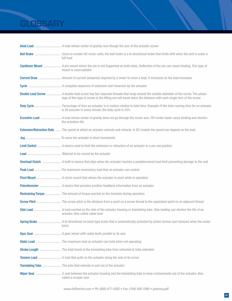
www.duffnorton.com • Ph: (800) 477-5002 • Fax: (704) 588-1994 • glossary.pdf
87
GLOSSARY
Axial Load ................................ A load whose center of gravity runs though the axis of the actuator screw
Ball Brake ................................ Used on smaller AC motor units, the ball brake is a bi-directional brake that limits drift when the unit is under a full load
Cantilever Mount ..................... A pin mount where the pin is not Supported on both sides. Defl ection of the pin can cause binding. This type of mount is unacceptable
Current Draw ........................... Amount of current (amperes) required by a motor to move a load. It increases as the load increases
Cycle ........................................ A complete sequence of extension and retraction by the actuator
Double Lead Screw .................. A double lead screw has two separate threads that wrap around the outside diameter of the screw. The advan-tage of this type of screw is the lifting nut will travel twice the distance with each single turn of the screw
Duty Cycle ................................ Percentage of time an actuator is in motion relative to total time. Example: If the total running time for an actuator is 20 seconds in every minute, the duty cycle is 33%
Eccentric Load ......................... A load whose center of gravity does not go through the screw axis. Off-center loads cause binding and shorten the actuators life
Extension/Retraction Rate ....... The speed at which an actuator extends and retracts. In DC models the speed can depend on the load
Jog ........................................... To move the actuator in short increments
Limit Switch ............................. A device used to limit the extension or retraction of an actuator to a pre-set position
Load ......................................... Material to be moved by the actuator
Overload Clutch ....................... A built-in device that slips when the actuator reaches a predetermined load limit preventing damage to the unit
Peak Load ................................ The maximum momentary load that an actuator can control
Pivot Mount .............................. A clevis mount that allows the actuator to pivot while in operation
Potentiometer .......................... A device that provides position feedback information from an actuator
Restraining Torque ................... The amount of torque exerted on the brackets during operation
Screw Pitch ............................. The screw pitch is the distance from a point on a screw thread to the equivalent point on an adjacent thread
Side Load ................................. A load exerted on the side of the actuator housing or translating tube. Side loading can shorten the life of an actuator. Also called radial load
Spring Brake ............................ A bi-directional no-back type brake that is automatically activated by pinion torsion and released when the motor turns
Spur Gear ................................. A gear wheel with radial teeth parallel to its axis
Static Load ............................... The maximum load an actuator can hold when not operating
Stroke Length .......................... The total travel of the translating tube from retracted to fully extended
Tension Load ............................ A load that pulls on the actuator along the axis of its screw
Translating Tube ....................... The tube that extends in and out of the actuator
Wiper Seal ............................... A seal between the actuator housing and the translating tube to keep contaminants out of the actuator. Also called a scraper seal

www.duffnorton.com • Ph: (800) 477-5002 • Fax: (704) 588-1994 • PDF:
7
© Yale Industrial Products, Inc., Duff-Norton Division, 2010All rights reserved by Yale Industrial Products, Inc., Duff-Norton Division.May not be copied in whole or in part.Printed in the USA
EMCAT5M MU 09/10
ISO 9001:2000 A
2574
Duff-Norton ®
Duff-Norton Also Manufactures...
Screw Jacks Cubic Screw Jacks Bevel GearScrew Jacks
Screws & Nuts
P.O. Box 7010 • Charlotte, NC 28241-7010Phone: (800) 477-5002 • (704) 588-4610
Fax: (704) 588-1994Email: [email protected]
www.duffnorton.com