linear analysis techniques in - powerworld · [email protected] 2001 south first street...
TRANSCRIPT

[email protected]://www.powerworld.com
2001 South First StreetChampaign, Illinois 61820+1 (217) 384.6330
2001 South First StreetChampaign, Illinois 61820+1 (217) 384.6330
Linear Analysis Techniques in PowerWorld Simulator
An overview of the underlying mathematics of the power flow and
linearized analysis techniques
2© 2015 PowerWorld CorporationLinear Analysis Techniques
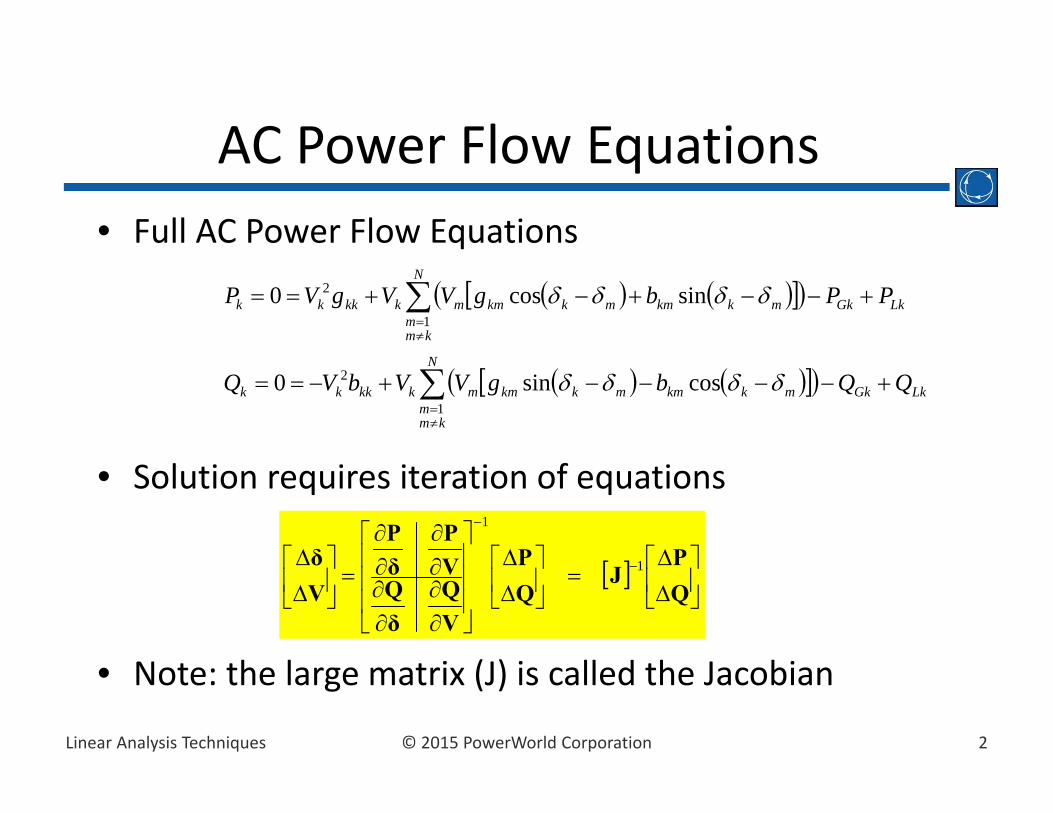
AC Power Flow Equations• Full AC Power Flow Equations
• Solution requires iteration of equations
• Note: the large matrix (J) is called the Jacobian
LkGk
N
kmm
mkkmmkkmmkkkkk
LkGk
N
kmm
mkkmmkkmmkkkkk
QQbgVVbVQ
PPbgVVgVP
1
2
1
2
cossin0
sincos0
QP
JQP
VQ
δQ
VP
δP
Vδ 1
1
3© 2015 PowerWorld CorporationLinear Analysis Techniques
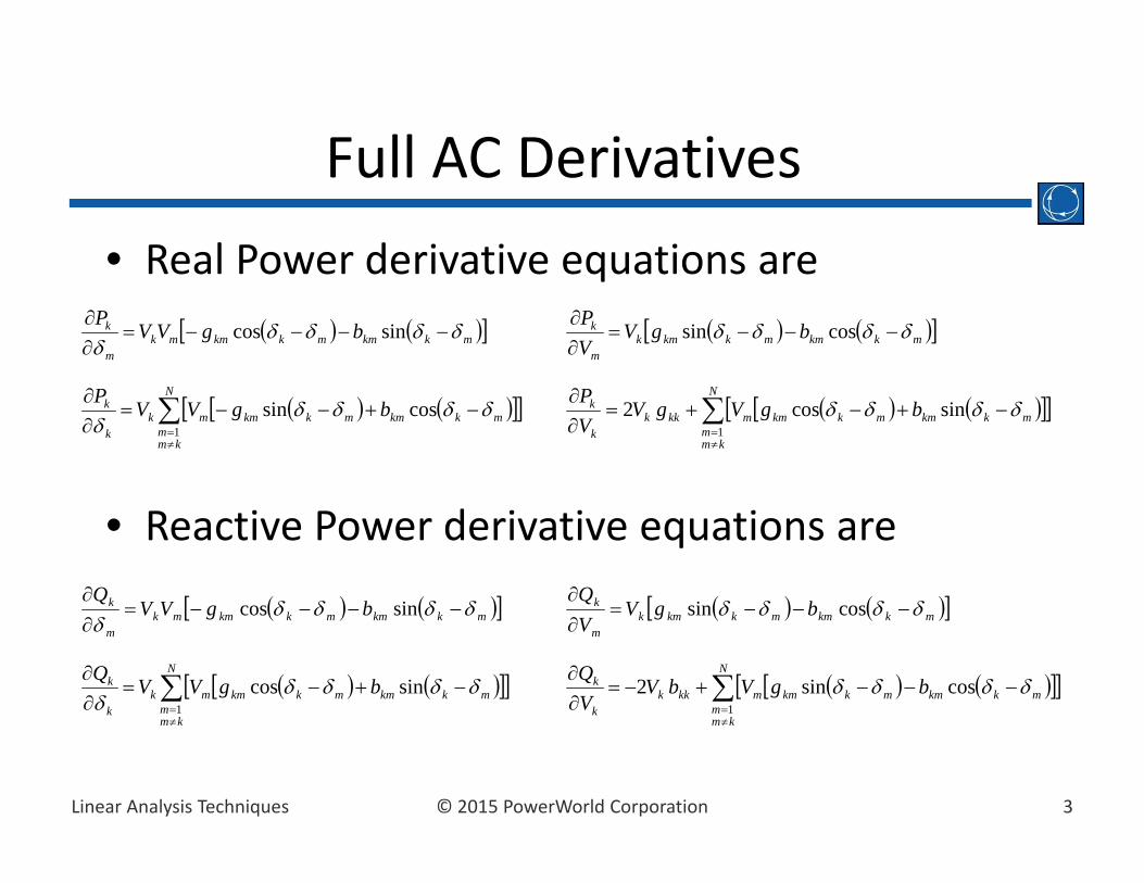
Full AC Derivatives• Real Power derivative equations are
• Reactive Power derivative equations are
N
kmm
mkkmmkkmmkkkk
k bgVgVVP
1
sincos2
N
kmm
mkkmmkkmmkk
k bgVVP1
cossin
N
kmm
mkkmmkkmmkkkk
k bgVbVVQ
1
cossin2
N
kmm
mkkmmkkmmkk
k bgVVQ1
sincos
mkkmmkkmkm
k bgVVP
cossin mkkmmkkmmk
m
k bgVVP
sincos
mkkmmkkmkm
k bgVVQ
cossin mkkmmkkmmkm
k bgVVQ
sincos

4© 2015 PowerWorld CorporationLinear Analysis Techniques
Decoupled Power Flow Equations• Make the following assumptions
• Derivatives simplify to
• Note: If assumption is insteadthen replace all with
• Option in Simulator Options under Power Flow Solution, DC Options sub‐tab
1kV 0kmg0 mk 0sin mk
1cos mk
0
k
k
VP
N
kmm
kmk
k bP1
0
m
k
VP
kmm
k bP
N
kmm
kmkkk
k bbVQ
1
)(2
0
k
kQkm
m
k bVQ
0
m
kQ
0kmrkmb kmx1
5© 2015 PowerWorld CorporationLinear Analysis Techniques
Other Typical Assumptions about Transformers
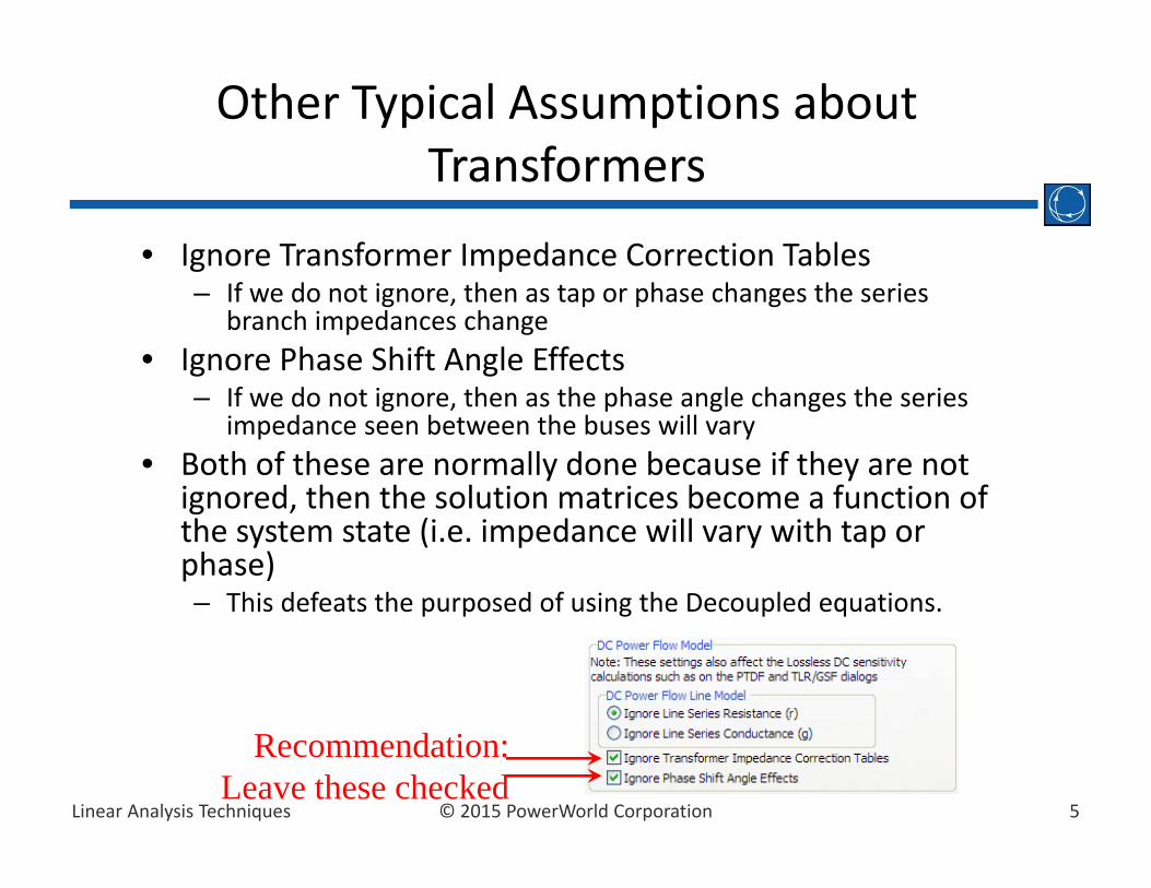
• Ignore Transformer Impedance Correction Tables– If we do not ignore, then as tap or phase changes the series
branch impedances change• Ignore Phase Shift Angle Effects
– If we do not ignore, then as the phase angle changes the series impedance seen between the buses will vary
• Both of these are normally done because if they are not ignored, then the solution matrices become a function of the system state (i.e. impedance will vary with tap or phase)– This defeats the purposed of using the Decoupled equations.
Recommendation:Leave these checked
6© 2015 PowerWorld CorporationLinear Analysis Techniques
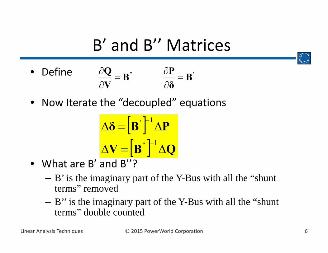
B’ and B’’ Matrices• Define
• Now Iterate the “decoupled” equations
• What are B’ and B’’?– B’ is the imaginary part of the Y-Bus with all the “shunt
terms” removed– B’’ is the imaginary part of the Y-Bus with all the “shunt
terms” double counted
'BδP
''B
VQ
QBV
PBδ
1''
1'

7© 2015 PowerWorld CorporationLinear Analysis Techniques
“DC Power Flow”• The “DC Power Flow” equations are simply the real part of the decoupled power flow equations– Voltages and reactive power are ignored– Only angles and real power are solved for by iterating
PBδ 1'

8© 2015 PowerWorld CorporationLinear Analysis Techniques
Bus Voltage and Angle Sensitivities to a Transfer
• Power flow was solved by iterating
• Model the transfer as a change in the injections P– Buyer:– Seller:
• Then solve for the voltage and angle sensitivities by solving
• These are the sensitivities of the Buyer and Seller “sending power to the slack bus”
QP
JVδ 1
TSySxS PFPF 0000T 1
1
N
zSzPF
TBgBfB PFPF 0000T 1
1
N
hBhPF
0T
JVδ S
S
S 1
0T
JVδ B
B
B 1

9© 2015 PowerWorld CorporationLinear Analysis Techniques
What about Losses?• If we assume the total sensitivity to the transfer is the seller minus the buyer sensitivity, then and
• This makes assumption that ALL the change in losses shows up at the slack bus.
• Simulator assigns the change to the BUYER by defining
• Then
BS δδδ BS VVV
slack power to sendingbuyer for generation busslack in Changeslack power to sendingseller for generation busslack in Change
B
S
SlackSlackk
B
B
S
S kVδ
Vδ
Vδ

10© 2015 PowerWorld CorporationLinear Analysis Techniques
Why does “k” assign the losses to the Buyer?

11© 2015 PowerWorld CorporationLinear Analysis Techniques
Lossless DC Voltage and Angle Sensitivities
• Use the DC Power Flow Equations
• Then determine angle sensitivities
• The DC Power Flow ignores losses, thus
PBδ 1'
SS TBδ 1' BB TBδ
1'
BS δδδ

12© 2015 PowerWorld CorporationLinear Analysis Techniques
Lossless DC Sensitivities with Phase Shifters Included
• DC Power Flow equations• Augmented to include an equation that describes the change in flow on a phase‐shifter controlled branch as being zero.
• Thus instead of DC power flow equations we use
• Otherwise process is the same.
PδB '
0αBδB Change Flow Line
0P
BB0B
αδ
1'

13© 2015 PowerWorld CorporationLinear Analysis Techniques
Lossless DC with Phase Shifters
• Phase Shifters are often on lower voltage paths (230 kV or less) with relatively small limits– They are put there in order to
manage/prevent the flow on a path that would commonly see overloads
– Thus, they constantly show up as “overloaded” when using linear analysis if they are not accounted for
• Example: Border of Canada with Northwestern United States– PTDFs between Canada and US without
Phase‐Shifters• 85% on 500 kV Path • 15% on Eastern Path
– PTDF With Phase‐Shifters• 100% goes on 500 kV Path• 0% on Eastern Path• This better reflects real system
230 kV Phase Shifter
115 kV Phase Shifter
115 kV Phase ShifterCalifornia
Canada
BPA
500 kV Path

14© 2015 PowerWorld CorporationLinear Analysis Techniques
Power Transfer Distribution Factors (PTDFs)
• PTDF: measures the sensitivity of line MW flows to a MW transfer. – Line flows are simply a function of the voltages and angles at its terminal buses
– Thus, the PTDF is simply a function of these voltage and angle sensitivities.
• This is the “Chain Rule” from Calculus
• Pkm is the flow from bus k to bus m
mm
kmK
k
kmm
m
kmK
k
kmkm
PPVVPV
VPPPTDF
Voltage and Angle Sensitivities that were just determined

15© 2015 PowerWorld CorporationLinear Analysis Techniques
Pkm Derivative Calculations• Full AC equations
• Lossless DC Approximations yields
PV
V g V g bkm
kk kk m km k m km k m2 cos sin
PV
V g bkm
mk km k m km k mcos sin
PV V g bkm
kk m km k m km k m
sin cos
PV V g bkm
mk m km k m km k m
sin cos
0
k
km
VP 0
m
km
VP
kmk
km bP
km
m
km bP

16© 2015 PowerWorld CorporationLinear Analysis Techniques
What do Flow Sensitivities (PTDFs, GSFs, TLRs, …) give us?
• Give the ability to model a change in power injection without actually doing a new power flow solution– Transfer of power between two places– Generator outage– Load outage
• Still can’t model a line outage or line closure yet, but that is what LODFs will give us

17© 2015 PowerWorld CorporationLinear Analysis Techniques
Line Outage Distribution Factors (LODFs)
• LODFl,k: percent of the pre-outage flow on Line K will show up on Line L after the outage of Line K
• Linear impact of an outage is determined by modeling the outage as a “transfer” between the terminals of the line
k
klkl P
PLODF ,
,

18© 2015 PowerWorld CorporationLinear Analysis Techniques
AssumeThen the flow on the Switches is ZERO, thusOpening Line K is equivalent to the “transfer”
Modeling an LODF as a Transfer
Line k
n m
Other Line l
The Rest of System
Pn Pm kP~
Switches
mnk PPP ~
mn PP and
Create a transfer defined by
19© 2015 PowerWorld CorporationLinear Analysis Techniques
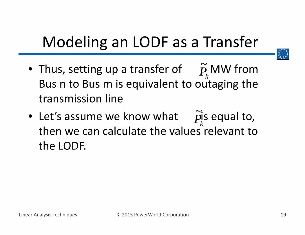
Modeling an LODF as a Transfer• Thus, setting up a transfer of MW from Bus n to Bus m is equivalent to outaging the transmission line
• Let’s assume we know what is equal to, then we can calculate the values relevant to the LODF.
kP~
kP~
20© 2015 PowerWorld CorporationLinear Analysis Techniques
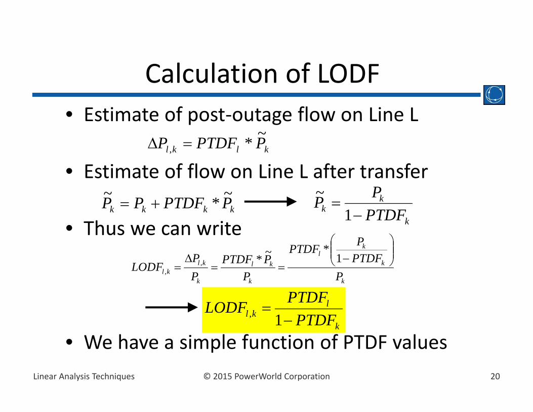
Calculation of LODF• Estimate of post‐outage flow on Line L
• Estimate of flow on Line L after transfer
• Thus we can write
• We have a simple function of PTDF values
klkl PPTDFP ~*,
kkkk PPTDFPP ~*~ k
kk PTDF
PP
1
~
k
k
kl
k
kl
k
klkl P
PTDFPPTDF
PPPTDF
PP
LODF
1
*~*,,
k
lkl PTDF
PTDFLODF
1,

21© 2015 PowerWorld CorporationLinear Analysis Techniques
Line Closure Distribution Factors (LCDFs)
• LCDFl,k: percent of the post‐closure flow on Line K will show up on Line L after the closure of Line K
• Linear impact of an closure is determined by modeling the closure as a “transfer” between the terminals of the line
k
klkl P
PLCDF ~
,,

22© 2015 PowerWorld CorporationLinear Analysis Techniques
Modeling the LCDF as a Transfer
Line k n m
Other Line l
The Rest of System
PnPm
kP~
Net flow from rest of the system
Net flow to rest ofthe system
AssumeThen the net flow to and from the rest of the system are both zero, thus closing line k is equivalent the “transfer”
mnk PPP ~mn PP and
Create a “transfer” defined by

23© 2015 PowerWorld CorporationLinear Analysis Techniques
Modeling an LCDF as a Transfer• Thus, setting up a transfer of MW from Bus n to Bus m is linearly equivalent to outaging the transmission line
• Let’s assume we know what is equal to, then we can calculate the values relevant to the LODF.
• Note: The negative sign is used so that the notation is consistent with LODF “transfer”
kP~
kP~

24© 2015 PowerWorld CorporationLinear Analysis Techniques
Calculation of LCDF• Estimate of post‐closure flow on Line L
• Thus we can write
• Thus the LCDF, is exactly equal to the PTDF for a transfer between the terminals of the line
klkl PPTDFP ~*,
lkl PTDFLCDF ,
lk
kl
k
klkl PTDF
PPPTDF
PP
LCDF
~~*
~,
,

25© 2015 PowerWorld CorporationLinear Analysis Techniques
LODF and LCDF• LODF (LCDF) – Gives the ability to model a single line
outage (closure) event– OTDF – incremental impact on a particular branch while also
considering a single line outage– OMW – estimate of the flow on a particular branch after a single
line outage
• Still can’t model multiple line outages simultaneously– Can not just sum because the lines that are being outaged also
interact with each other
11,1, * PTDFLODFPTDFOTDF MMM
11,1, * MWLODFMWOMW MMM
slineoutagek
kkMMKM PTDFLODFPTDFOTDF *,,
slineoutagek
kkMMKM MWLODFMWOMW *,,
26© 2015 PowerWorld CorporationLinear Analysis Techniques
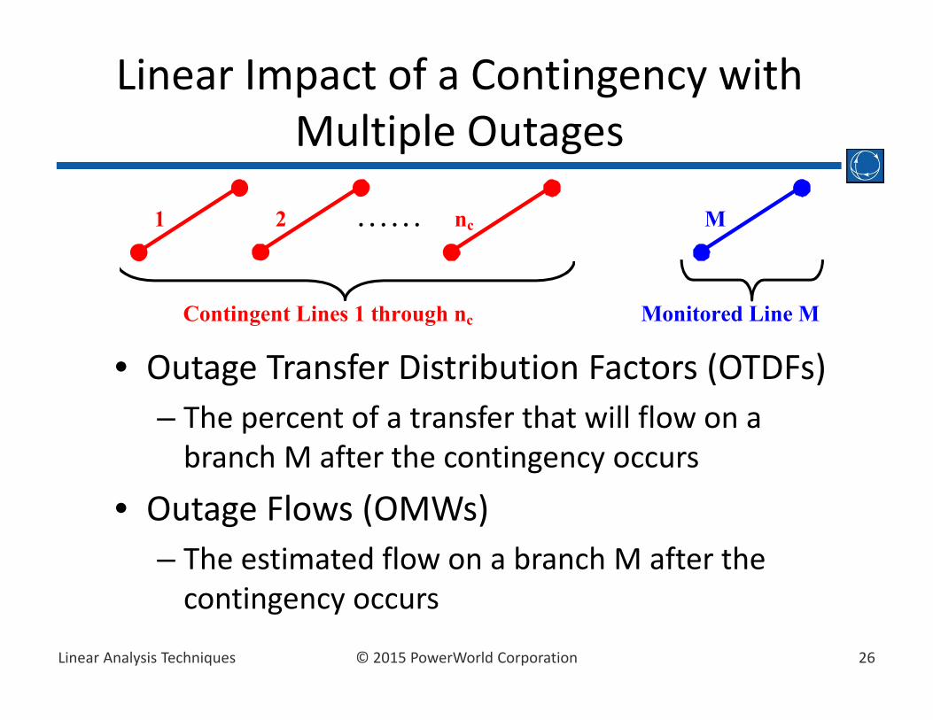
Linear Impact of a Contingency with Multiple Outages
• Outage Transfer Distribution Factors (OTDFs)– The percent of a transfer that will flow on a branch M after the contingency occurs
• Outage Flows (OMWs)– The estimated flow on a branch M after the contingency occurs
1 2 nc. . . . . . M
Contingent Lines 1 through nc Monitored Line M

27© 2015 PowerWorld CorporationLinear Analysis Techniques
OTDFs and OMWs• Single Contingency
• Multiple Contingencies
• What are and ?
11,1, * PTDFLODFPTDFOTDF MMM
11,1, * MWLODFMWOMW MMM
Cn
KKMKMCM NetPTDFLODFPTDFOTDF
1, *
Cn
KKMKMCM NetMWLODFMWOMW
1, *
KNetPTDF KNetMW

28© 2015 PowerWorld CorporationLinear Analysis Techniques
Determining NetPTDFKand NetMWK
• Each NetPTDFK is a function of all the other NetPTDFs because the change in status of a line affects all other lines.
• Assume we know all NetPTDFs except for NetPTDF1. Then we can write:
• In general for each Contingent Line N, write
C
CC
n
KKK
nn
NetPTDFLODFPTDF
NetPTDFLODFNetPTDFLODFPTDFNetPTDF
211
121211 ...
N
n
NKK
KNKN PTDFNetPTDFLODFNetPTDFC
1

29© 2015 PowerWorld CorporationLinear Analysis Techniques
• Thus we have a set of nc equations and ncunknowns (nc= number of contingent lines)
• Thus• Same type of derivation shows
Determining NetPTDFKand NetMWK
CCCCC
C
C
C
nnnnn
n
n
n
PTDF
PTDFPTDFPTDF
NetPTDF
NetPTDFNetPTDFNetPTDF
LODFLODFLODF
LODFLODFLODFLODFLODFLODFLODFLODFLODF
3
2
1
3
2
1
321
33231
22321
11312
1
11
1
CCCC PTDFLODFNetPTDF 1
CCCC MWLODFNetMW 1
Known Values
30© 2015 PowerWorld CorporationLinear Analysis Techniques
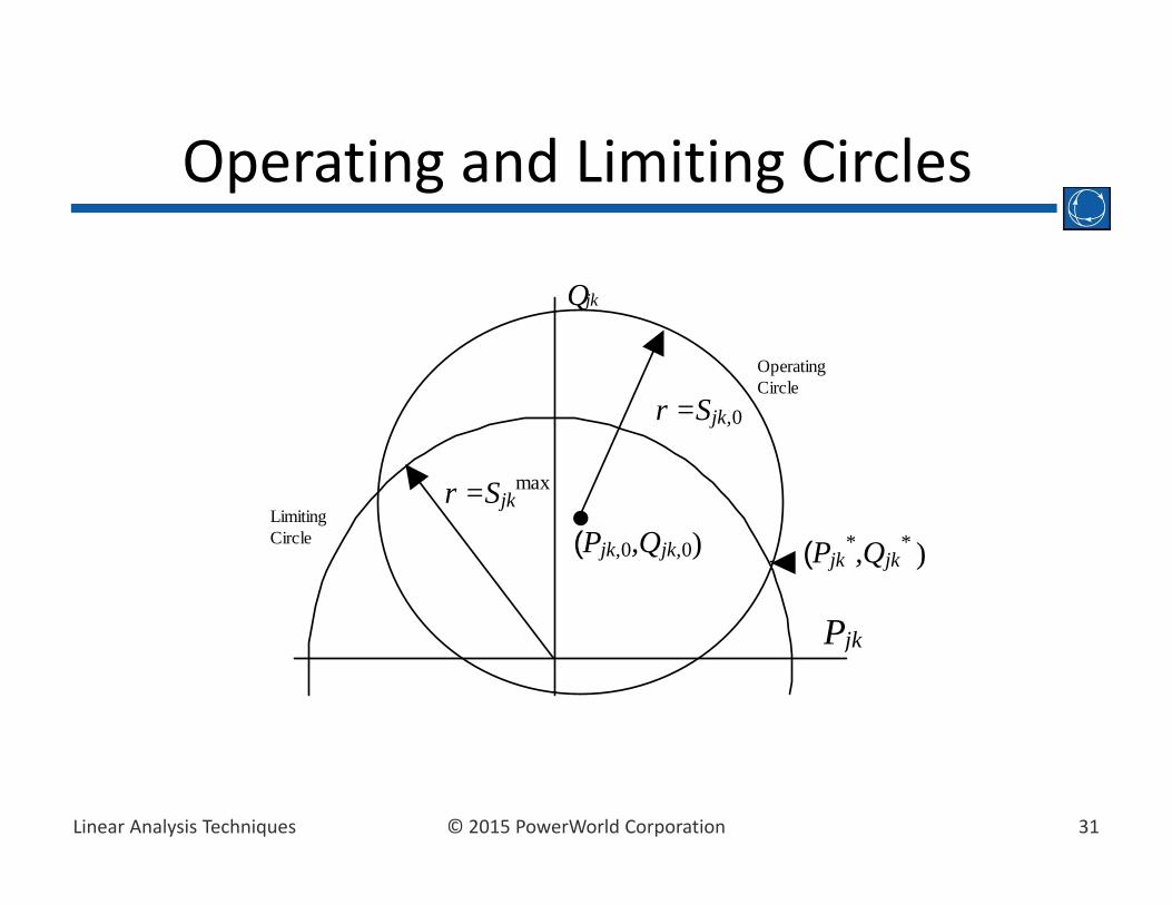
Operating and Limiting Circles• Operating circle defines a circle of valid MW and Mvar
values for a transmission line as a transfer takes place across the system
• Limiting circle has a radius equal to the MVA limit of the line
• The operating circle is utilized when using one of the DC methods and modeling reactive power by assuming constant voltage magnitudes
• Contingency analysis looks up the Mvar value corresponding to the calculated MW value
• ATC analysis and DC power flow find the intersection of the operating circle and the limiting circle to assign adjusted limits to lines
31© 2015 PowerWorld CorporationLinear Analysis Techniques
Operating and Limiting Circles
r =Sjkmax
Limiting Circle
Qjk
P jk
Operating Circle
r =Sjk,0
(Pjk,0,Qjk,0) (Pjk*,Qjk
* )