linear collider damping rings andy wolski lawrence berkeley national laboratory uspas santa barbara,...
TRANSCRIPT
Linear Collider Damping Rings
Andy Wolski
Lawrence Berkeley National Laboratory
USPAS Santa Barbara, June 2003
2
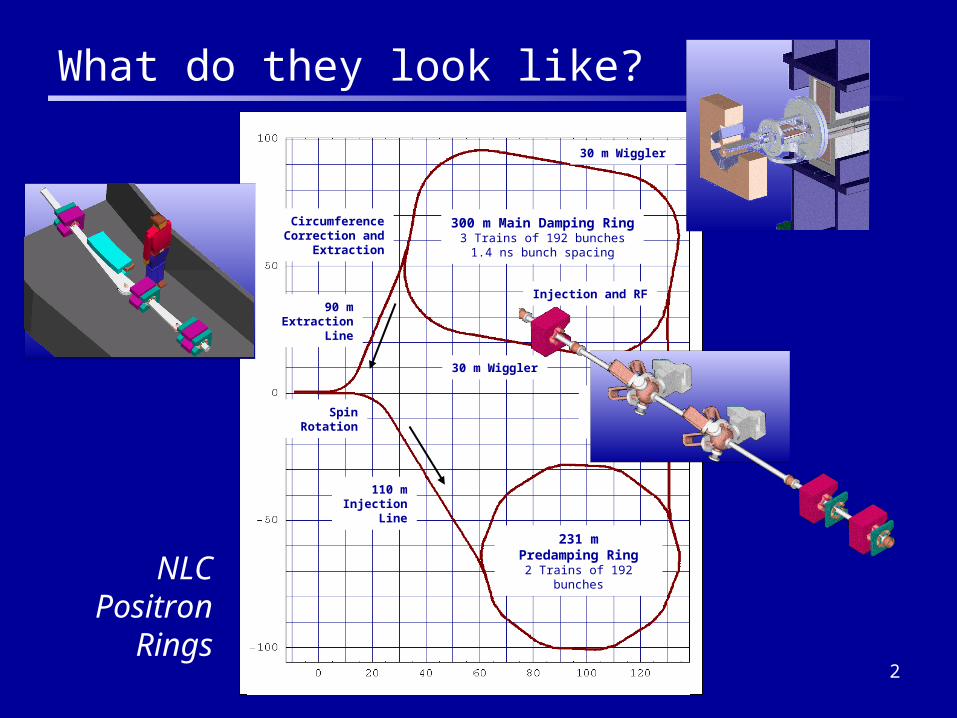
300 m Main Damping Ring3 Trains of 192 bunches
1.4 ns bunch spacing
231 mPredamping Ring
2 Trains of 192 bunches
30 m Wiggler
30 m Wiggler
Injection and RF
Circumference Correction and
Extraction
110 mInjection
Line
110 mTransfer
Line
90 mExtraction
Line
Spin Rotation
What do they look like?
NLC Positron
Rings
3
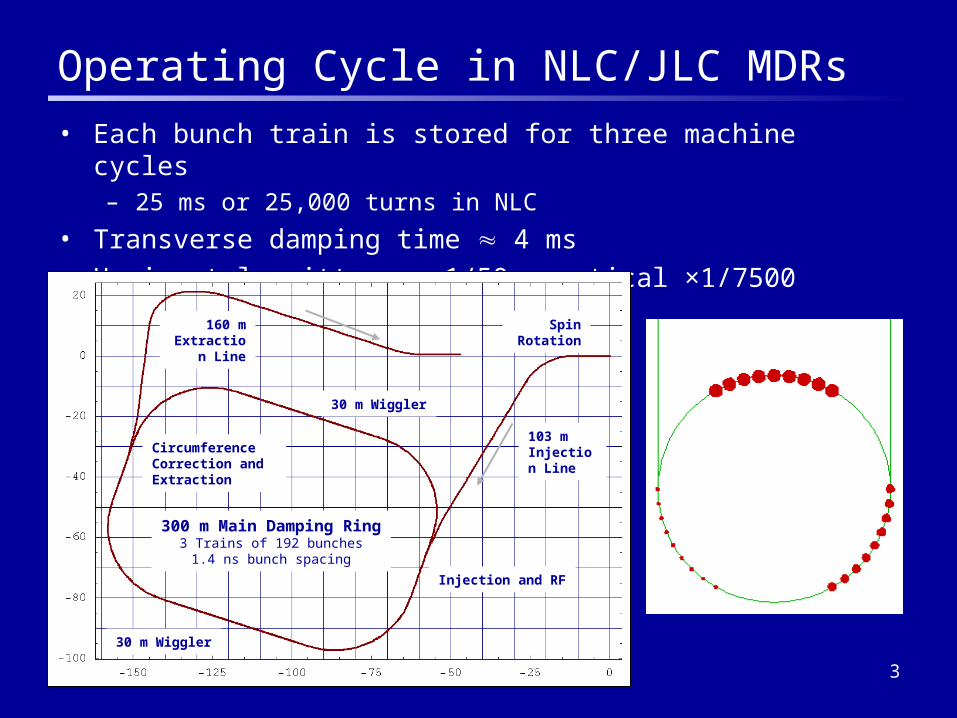
Operating Cycle in NLC/JLC MDRs
• Each bunch train is stored for three machine cycles– 25 ms or 25,000 turns in NLC
• Transverse damping time 4 ms
• Horizontal emittance ×1/50, vertical ×1/7500
300 m Main Damping Ring3 Trains of 192 bunches
1.4 ns bunch spacing
30 m Wiggler
30 m Wiggler
Injection and RF
Circumference Correction and Extraction
103 mInjection Line
160 mExtraction
Line
Spin Rotation
4
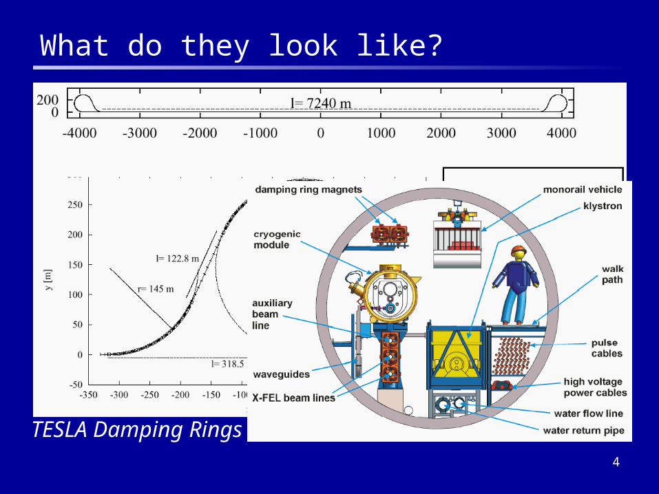
What do they look like?
TESLA Damping Rings
5
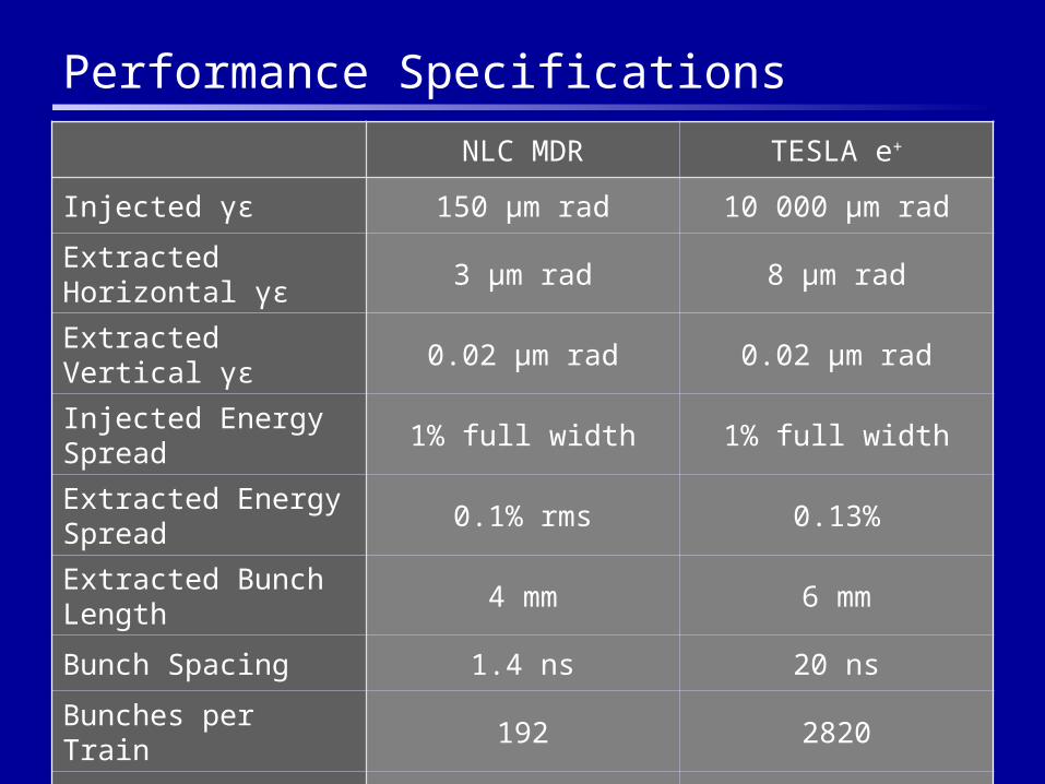
Performance Specifications
NLC MDR TESLA e+
Injected γε 150 µm rad 10 000 µm rad
Extracted Horizontal γε 3 µm rad 8 µm rad
Extracted Vertical γε 0.02 µm rad 0.02 µm rad
Injected Energy Spread 1% full width 1% full width
Extracted Energy Spread 0.1% rms 0.13%
Extracted Bunch Length 4 mm 6 mm
Bunch Spacing 1.4 ns 20 ns
Bunches per Train 192 2820
Repetition Rate 120 Hz 5 Hz
6
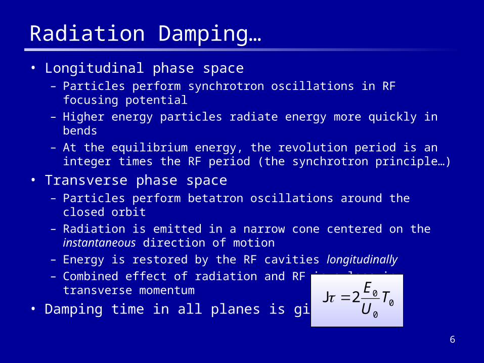
Radiation Damping…
• Longitudinal phase space– Particles perform synchrotron oscillations in RF focusing potential
– Higher energy particles radiate energy more quickly in bends
– At the equilibrium energy, the revolution period is an integer times the RF period (the synchrotron principle…)
• Transverse phase space– Particles perform betatron oscillations around the closed orbit
– Radiation is emitted in a narrow cone centered on the instantaneous direction of motion
– Energy is restored by the RF cavities longitudinally
– Combined effect of radiation and RF is a loss in transverse momentum
• Damping time in all planes is given by:0
0
02 TU
EJ

7
…and Quantum Excitation
• Radiation is emitted in discrete quanta
• Number and energy distribution etc. of photons obeystatistical laws
• Radiation process can be modeled as a series of “kicks” that excite longitudinal and transverse oscillations
8
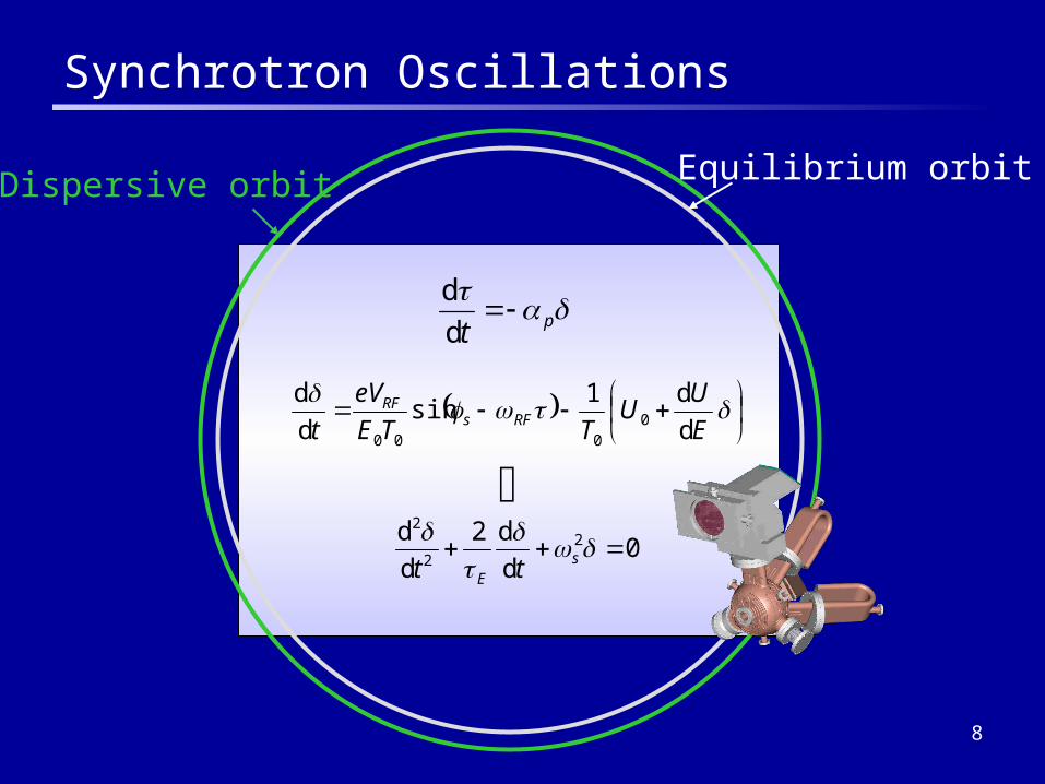
Synchrotron Oscillations
pt
d
d
E
UU
TTE
eV
t RFsRF
d
d1sin
d
d0
000
0d
d2
d
d 22
2
s
E tt
Equilibrium orbitDispersive orbit
9
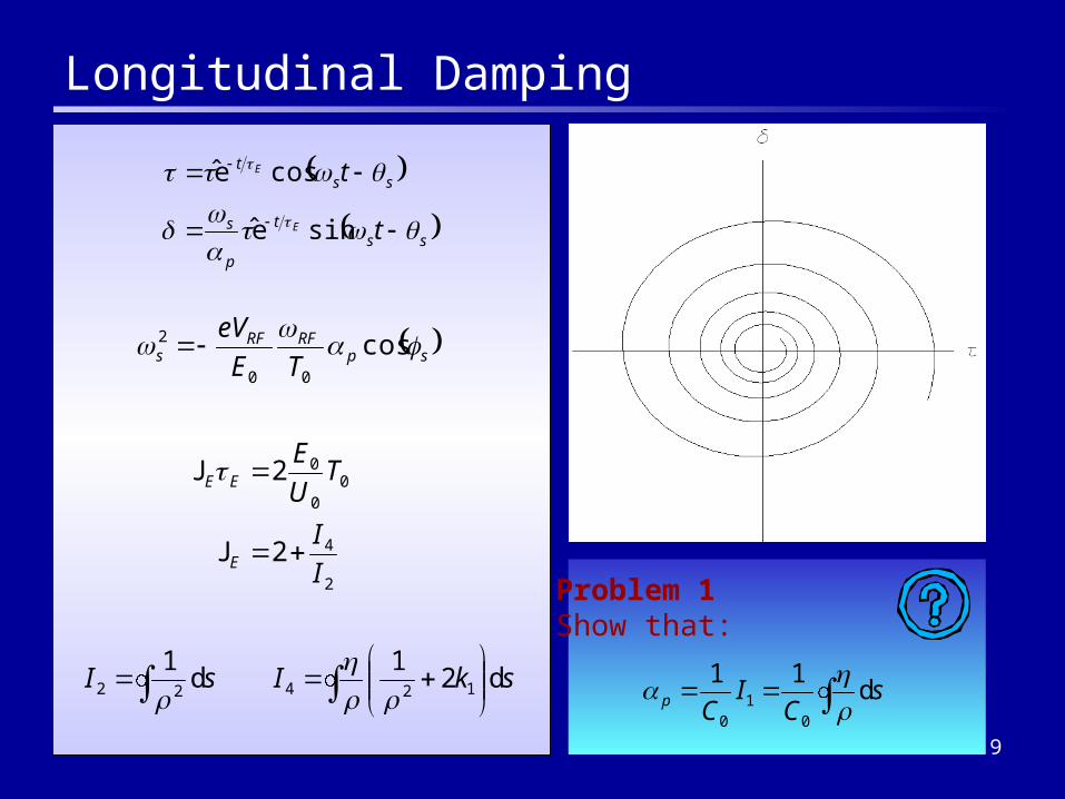
Longitudinal Damping
spRFRF
s TE
eV cos00
2
sst
p
s
sst
t
t
E
E
sine
cose
2
4
00
0
2
2
I
I
TU
E
E
EE
J
J
skIsI d2
1d
112422
Problem 1Show that:
sC
ICp d
11
01
0
10
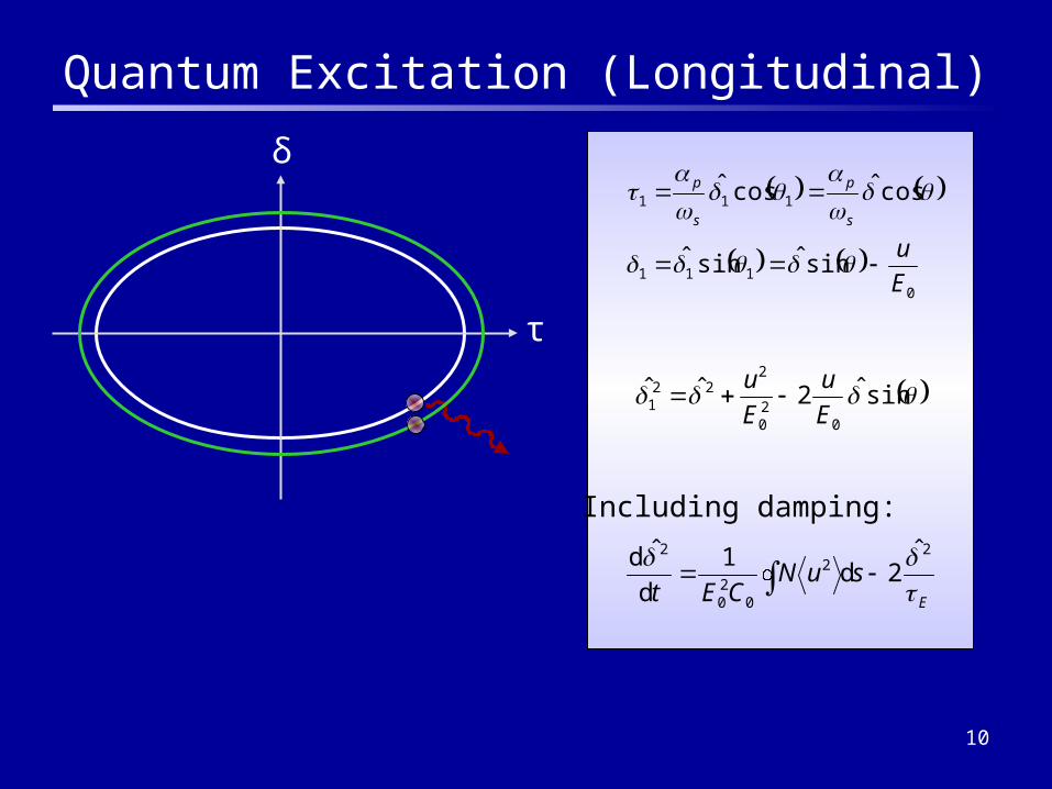
Quantum Excitation (Longitudinal)
δ
τ
0
111
111
sinˆsinˆ
cosˆcosˆ
E
us
p
s
p
sinˆ2ˆˆ0
20
222
1 E
u
E
u
E
suNCEt
22
020
2 ˆ2d
1
d
ˆd
Including damping:

11
Equilibrium Longitudinal Emittance
• We have found that:
• From synchrotron radiation theory:
sII
IECsuN
C EEq d
14d
133
2
320
22
0 J
Problem 2Find an expression for the equilibrium energy spread,and show that:
t
equt e1e ,0
E
suNCEt
22
020
2 ˆ2d
1
d
ˆd
12
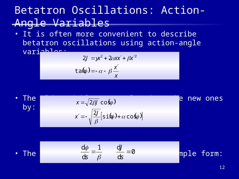
• It is often more convenient to describe betatron oscillations using action-angle variables:
• The old variables are related to the new ones by:
• The equations of motion take the simple form:
Betatron Oscillations: Action-Angle Variables
x
x
xxxxJ
tan
22 22
cossin2
cos2
Jx
Jx
0d
d1
d
d
s
J
s
13
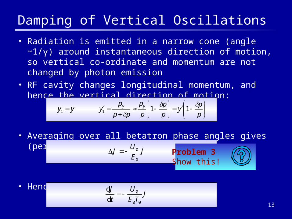
Damping of Vertical Oscillations
• Radiation is emitted in a narrow cone (angle ~1/γ) around instantaneous direction of motion, so vertical co-ordinate and momentum are not changed by photon emission
• RF cavity changes longitudinal momentum, and hence the vertical direction of motion:
• Averaging over all betatron phase angles gives (per turn):
• Hence the equation of motion is:
p
py
p
p
p
p
pp
pyyy yy
1111
JE
UJ
0
0
JTE
U
t
J
00
0
d
d
Problem 3Show this!
14
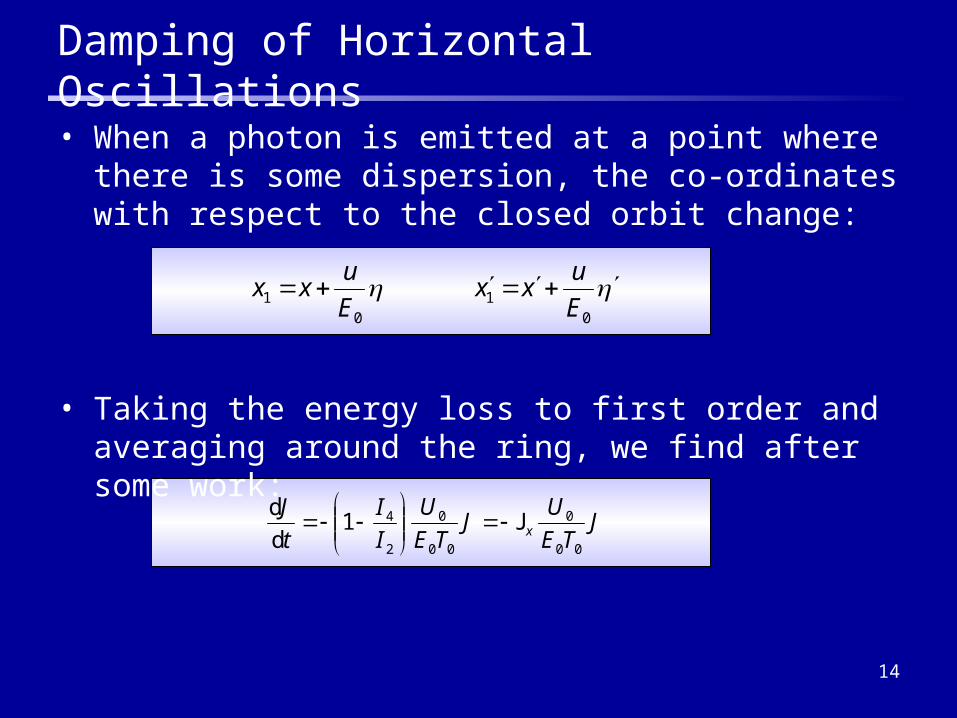
Damping of Horizontal Oscillations
• When a photon is emitted at a point where there is some dispersion, the co-ordinates with respect to the closed orbit change:
0
10
1 E
uxx
E
uxx
JTE
UJ
TE
U
I
I
t
Jx
00
0
00
0
2
41d
dJ
• Taking the energy loss to first order and averaging around the ring, we find after some work:
15
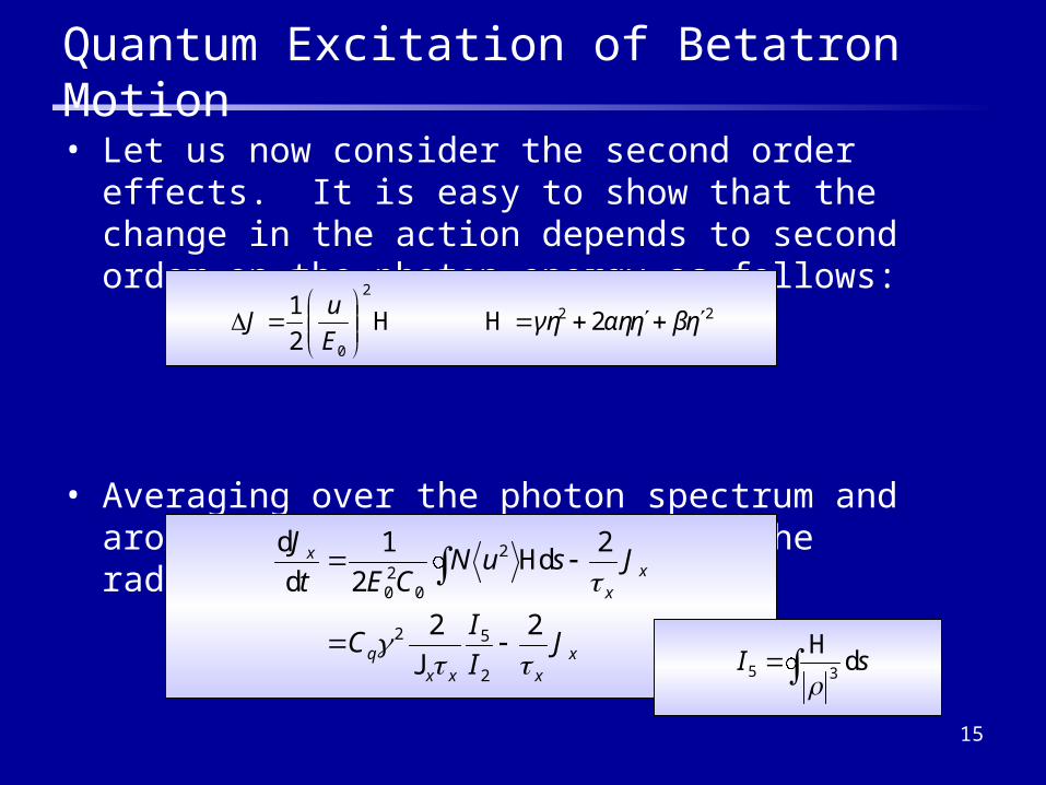
Quantum Excitation of Betatron Motion
• Let us now consider the second order effects. It is easy to show that the change in the action depends to second order on the photon energy as follows:
• Averaging over the photon spectrum and around the ring, and including the radiation damping gives:
22
2
0
22
1ηβηαηγη
E
uJ
HH
xxxx
q
xx
x
JI
IC
JsuNCEt
J
22
2d
2
1
d
d
2
52
2
020
J
H
sI d35H
16
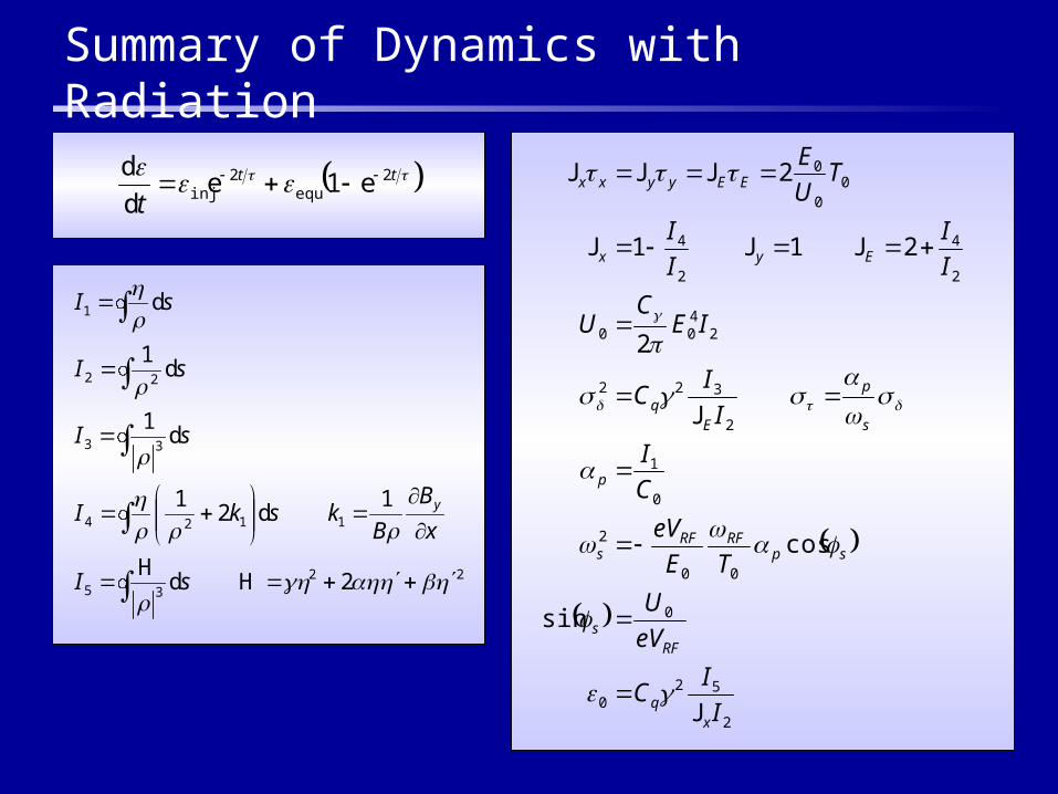
Summary of Dynamics with Radiation
2
520
0
00
2
0
1
2
322
2400
2
4
2
4
00
0
sin
cos
2
211
2
I
IC
eV
U
TE
eV
C
I
I
IC
IEC
U
I
I
I
I
TU
E
xq
RFs
spRFRF
s
p
s
p
Eq
Eyx
EEyyxx
J
J
JJJ
JJJ
tt
t2
equ2
inj e1ed
d
235
1124
33
22
1
2d
1d2
1
d1
d1
d
2HH
sI
x
B
BkskI
sI
sI
sI
y
17
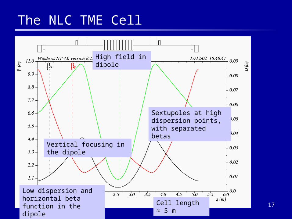
The NLC TME Cell
Low dispersion and horizontal beta function in the dipole
High field in dipole
Sextupoles at high dispersion points, with separated betas
Vertical focusing in the dipole
Cell length ≈ 5 m
18
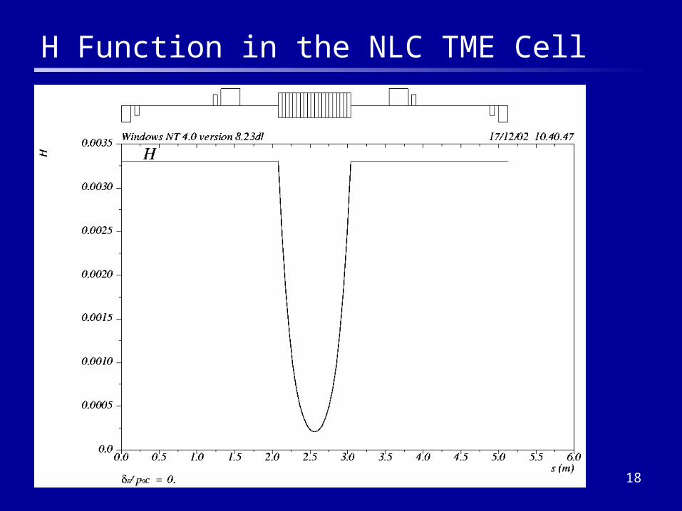
H Function in the NLC TME Cell

19
The TESLA TME Cell
Larger dispersion and horizontal beta function in the dipole
Low field in dipole
Sextupoles at high dispersion points
No vertical focusing in the dipole
Cell length ≈ 15 m

20
NLC and TESLA TME Cells Compared
• NLC– Compact cell to keep circumference as short as possible– High dipole field for greater energy loss, reducing wiggler length– Short dipole requires very low values for dispersion and beta function– Gradient in dipole field to improve transverse dynamics
• TESLA– Circumference fixed by bunch train and kicker rise/fall time– Long dipole for larger momentum compaction, longer bunch
• Optimum lattice functions at center of dipole:
– Obtained by minimizing I5 for a ring without a wiggler– It is not usually possible to control the dispersion and beta function
independently
151224152
32
min00
x
qCLL
J
21
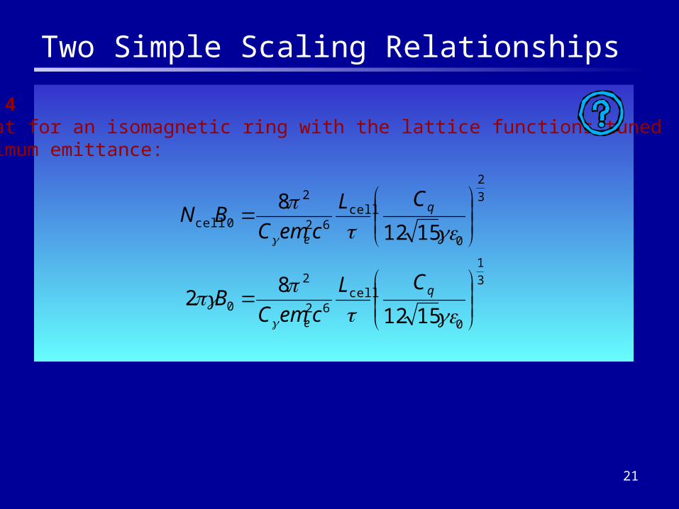
Two Simple Scaling Relationships
Problem 4Show that for an isomagnetic ring with the lattice functions tunedfor minimum emittance:
3
1
0
cell62
2
0
3
2
0
cell62
2
0cell
1512
82
1512
8
q
e
q
e
CL
cemCB
CL
cemCBN
22
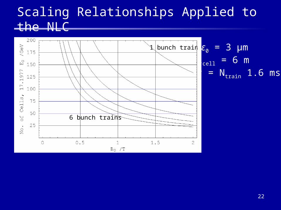
Scaling Relationships Applied to the NLC
1 bunch train
6 bunch trains
γε0 = 3 μmLcell = 6 mτ = Ntrain 1.6 ms
23
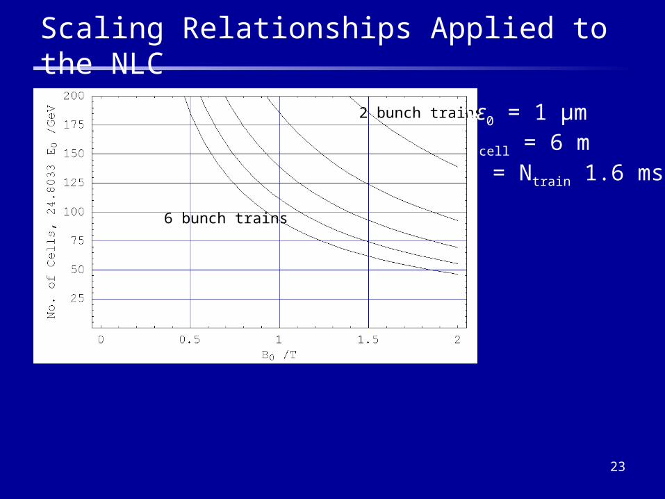
Scaling Relationships Applied to the NLC
2 bunch trains
6 bunch trains
γε0 = 1 μmLcell = 6 mτ = Ntrain 1.6 ms
24
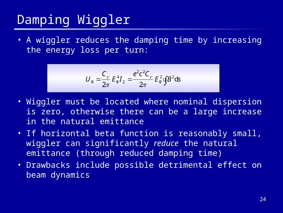
Damping Wiggler
• A wiggler reduces the damping time by increasing the energy loss per turn:
• Wiggler must be located where nominal dispersion is zero, otherwise there can be a large increase in the natural emittance
• If horizontal beta function is reasonably small, wiggler can significantly reduce the natural emittance (through reduced damping time)
• Drawbacks include possible detrimental effect on beam dynamics
sBECce
IEC
U d22
220
22
2400

25
Types of Wiggler
• A wiggler is simply a periodic array of magnets, such that the field is approximately sinusoidal
• Different technologies are possible:– Electromagnetic
– Permanent magnet
– Hybrid (permanent magnets driving flux through steel poles)
• Choice of technology comes down to cost optimization for given requirements on field strength and quality
• Both TESLA and NLC damping rings have opted for hybrid technology
26
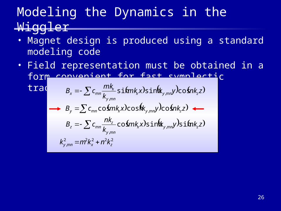
Modeling the Dynamics in the Wiggler
• Magnet design is produced using a standard modeling code
• Field representation must be obtained in a form convenient for fast symplectic tracking
22222,
,,
,
,,
sinsinhcos
coscoshcos
cossinhsin
zxmny
zmnyxmny
zmnz
zmnyxmny
zmnyxmny
xmnx
knkmk
znkykxmkk
nkcB
znkykxmkcB
znkykxmkk
mkcB
27
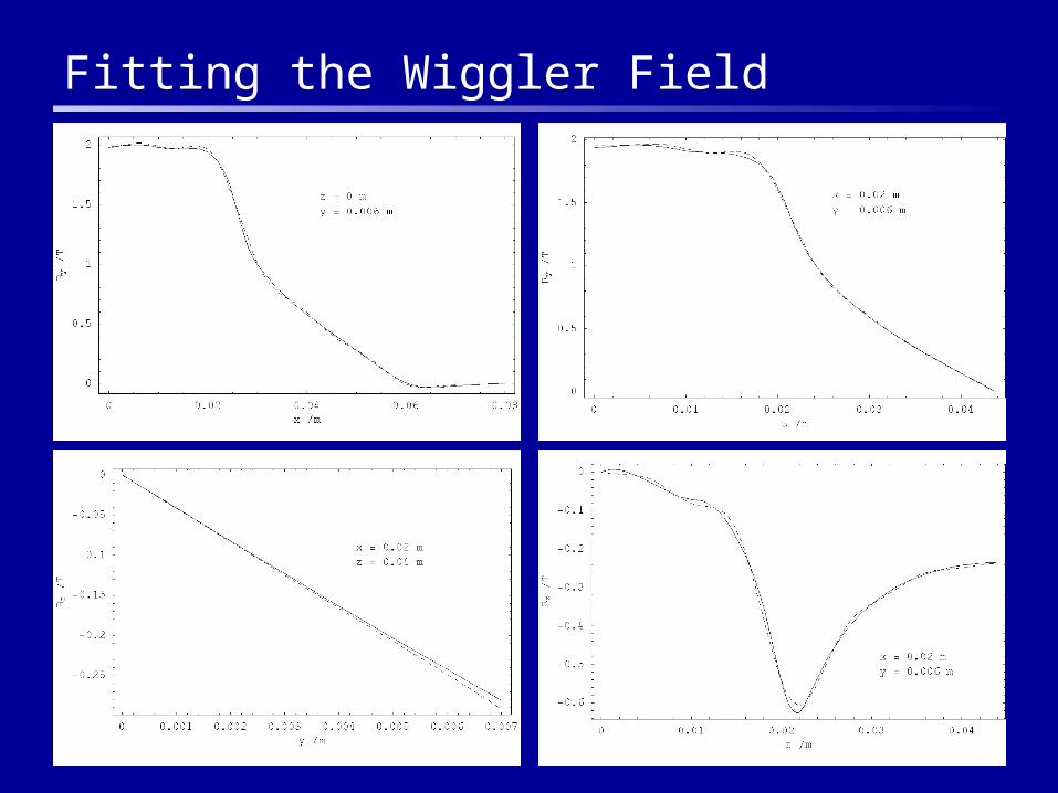
Fitting the Wiggler Field
28
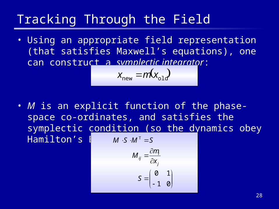
Tracking Through the Field
• Using an appropriate field representation (that satisfies Maxwell’s equations), one can construct a symplectic integrator:
• M is an explicit function of the phase-space co-ordinates, and satisfies the symplectic condition (so the dynamics obey Hamilton’s Equations):
oldnew xmx
01
10
T
S
x
mM
SMSM
j
iij
29
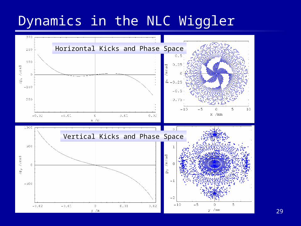
Dynamics in the NLC Wiggler
Horizontal Kicks and Phase Space
Vertical Kicks and Phase Space

30
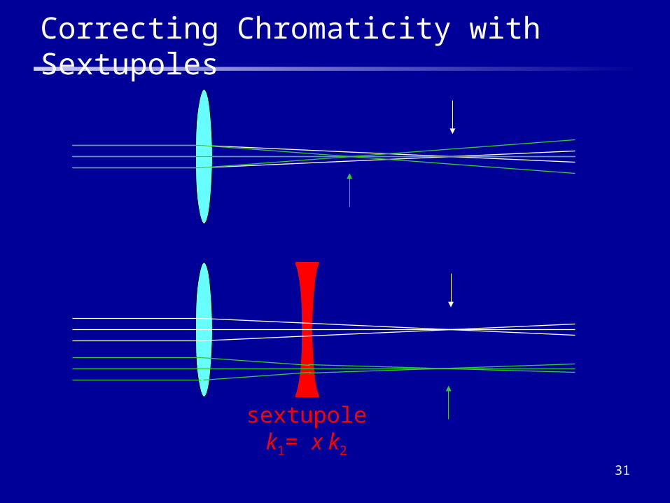
Chromaticity
• Chromaticity is the tune variation with energy• Quadrupole focusing strength gets smaller as particle energy
increases• It can easily be shown that:
• Since beta functions peak at the focusing quadrupoles in the appropriate plane, the natural chromaticity is always negative
• Chromaticity is connected to beam instabilities– particles with large energy deviation cross resonance lines– some collective effects (e.g. head-tail instability) are sensitive to the
chromaticity
sk
sk
yy
y
xx
x
d4
1
d4
1
1
1
31
sextupolek1= x k2
Correcting Chromaticity with Sextupoles
32
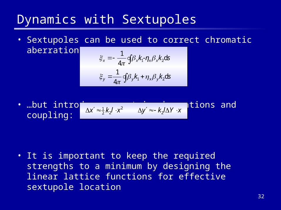
Dynamics with Sextupoles
• Sextupoles can be used to correct chromatic aberrations…
• …but introduce geometric aberrations and coupling:
• It is important to keep the required strengths to a minimum by designing the linear lattice functions for effective sextupole location
xYlkyxlkx 22
221
skk
sk-ηk
yyy
xxx
d4
1
d4
1
2x1
2x1
33
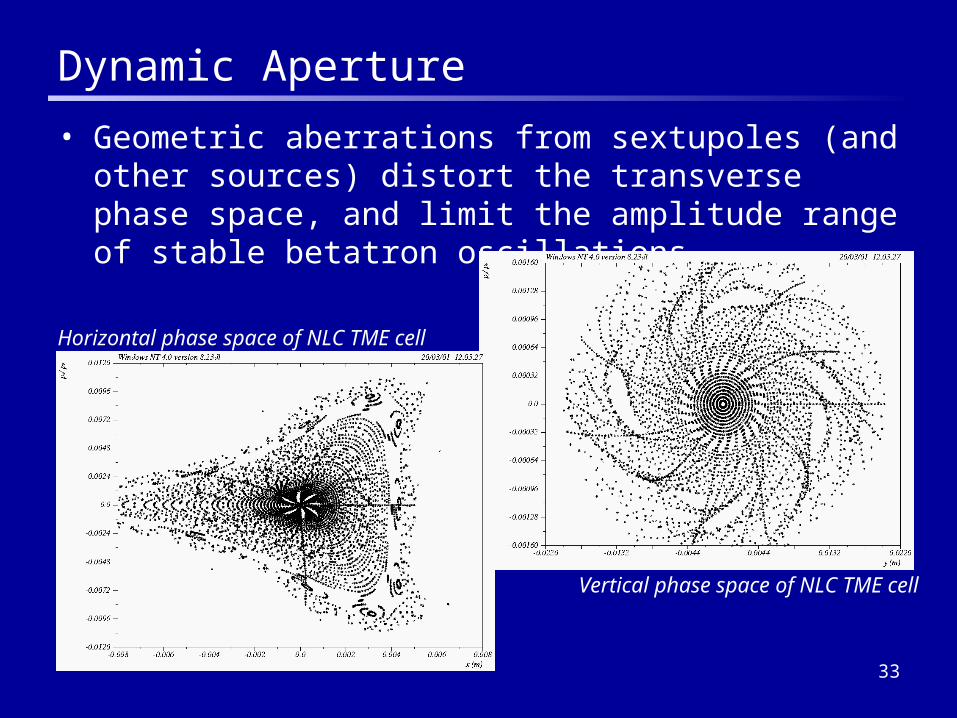
Dynamic Aperture
• Geometric aberrations from sextupoles (and other sources) distort the transverse phase space, and limit the amplitude range of stable betatron oscillations
Horizontal phase space of NLC TME cell
Vertical phase space of NLC TME cell
34
Transverse and Longitudinal Aperture
• Damping rings require a “large” dynamic aperture– Injected beam power ~ 50 kW average, and radiation load from any
significant injection losses will destroy the ring– Nonlinear distortion of the phase space may lead to transient emittance
growth from inability properly to match injected beam to the ring– For NLC Main Damping Rings, the target dynamic aperture is 15 times
the injected rms beam size
• We also need a large momentum acceptance– Injected beam has a large energy spread– Particles may be lost from insufficient physical aperture in dispersive
regions, or through poor off-momentum dynamics– Particles within a bunch can scatter off each other, leading to a
significant change in energy deviation (Touschek Effect)
• It is important to perform tracking studies with full dynamic model and physical apertures

35
NLC Main Damping Ring Dynamic Aperture
Dynamic Aperture On-Momentum
δ= +0.005
δ= -0.005
15× Injected Beam Size
36
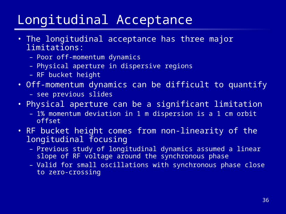
Longitudinal Acceptance
• The longitudinal acceptance has three major limitations:– Poor off-momentum dynamics– Physical aperture in dispersive regions– RF bucket height
• Off-momentum dynamics can be difficult to quantify– see previous slides
• Physical aperture can be a significant limitation– 1% momentum deviation in 1 m dispersion is a 1 cm orbit offset
• RF bucket height comes from non-linearity of the longitudinal focusing– Previous study of longitudinal dynamics assumed a linear slope of RF
voltage around the synchronous phase– Valid for small oscillations with synchronous phase close to zero-
crossing
37
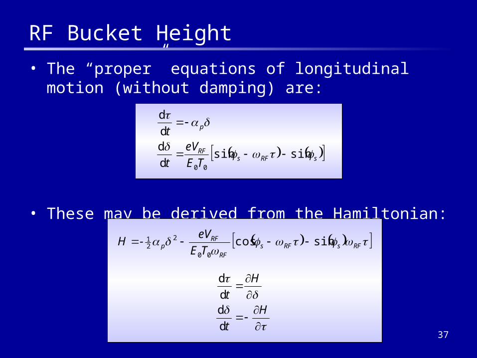
RF Bucket Height
• The “proper” equations of longitudinal motion (without damping) are:
• These may be derived from the Hamiltonian:
sRFsRF
p
TE
eV
t
t
sinsind
dd
d
00
RFsRFsRF
RFp TE
eV-H sincos
00
221
H
t
H
t
d
dd
d
38
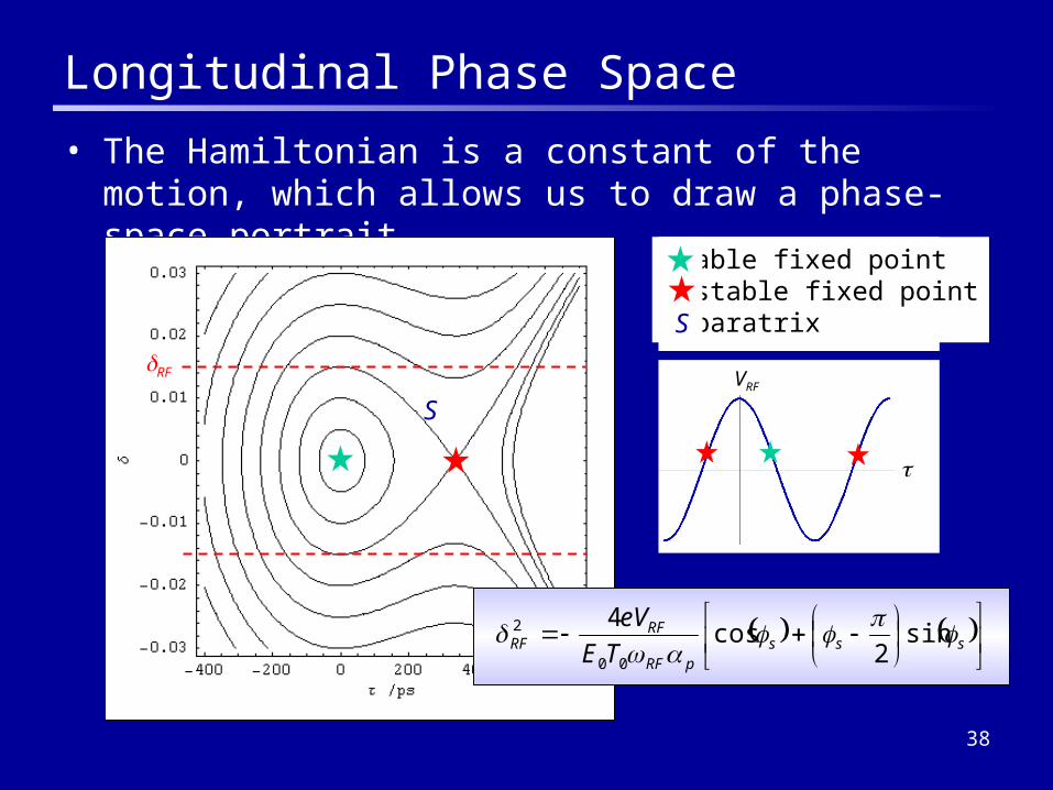
Longitudinal Phase Space
• The Hamiltonian is a constant of the motion, which allows us to draw a phase-space portrait
S
Stable fixed pointUnstable fixed pointSeparatrixS
VRF
sss
pRF
RFRF TE
eV
sin2
cos4
00
2
RF
39
Alignment Issues
• The final luminosity of the collider is critically dependent on the vertical emittance extracted from the damping rings
• In a perfectly flat lattice, the lower limit on the vertical emittance comes from the opening angle of the radiation– Gives about 10% of the specified values for NLC and TESLA
• Magnet misalignments give the dominant contribution to the vertical emittance– Quadrupole vertical misalignments
• Vertical dispersion
• Vertical beam offset in sextupoles
– Quadrupole rotations and sextupole vertical misalignments• Couple horizontal dispersion into the vertical plane
• Couple horizontal betatron oscillations into the vertical plane

40
Betatron Coupling
• In a damping ring, the dominant sources of betatron coupling are skew quadrupole fields– Normal quadrupoles have some “roll” about the beam axis
– Sextupoles have some vertical offset with respect to the closed orbit
• Particles with a horizontal offset get a vertical kick
Particle onclosed orbit
Particle withhorizontalamplitude
Vertical kickdepends onhorizontalamplitude
41
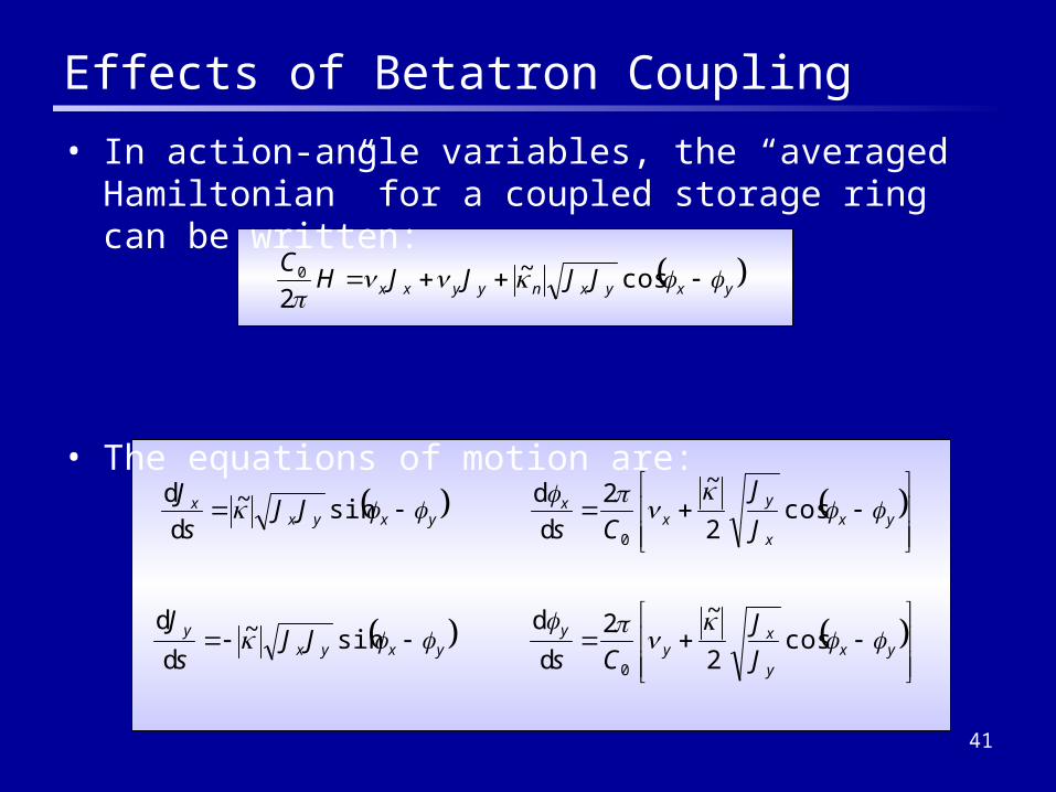
Effects of Betatron Coupling
• In action-angle variables, the “averaged Hamiltonian” for a coupled storage ring can be written:
• The equations of motion are:
yxyxnyyxx JJJJHC
cos~2
0
yxy
xy
yyxyx
y
yxx
yx
xyxyx
x
J
J
CsJJ
s
J
J
J
CsJJ
s
J
cos2
~2
d
dsin~
d
d
cos2
~2
d
dsin~
d
d
0
0
42
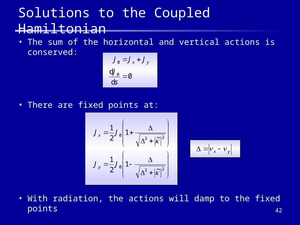
Solutions to the Coupled Hamiltonian
• The sum of the horizontal and vertical actions is conserved:
• There are fixed points at:
• With radiation, the actions will damp to the fixed points
0d
d 0
0
s
J
JJJ yx
220
220
~1
2
1
~1
2
1
JJ
JJ
y
x
yx
43
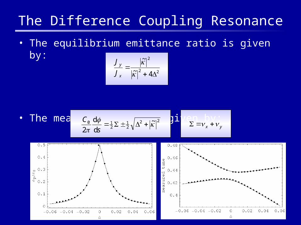
The Difference Coupling Resonance
• The equilibrium emittance ratio is given by:
• The measured tunes are given by:
22
2
4~
~
x
y
J
J
2221
210 ~
d
d
2
s
Cyx
44
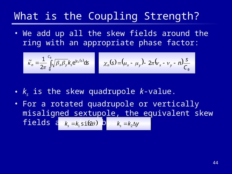
What is the Coupling Strength?
• We add up all the skew fields around the ring with an appropriate phase factor:
• ks is the skew quadrupole k-value.
• For a rotated quadrupole or vertically misaligned sextupole, the equivalent skew fields are given by:
skC
ssyxn
n de2
1~0
0
i
0
2C
sns yxyxn
2sin1kks ykks 2
45
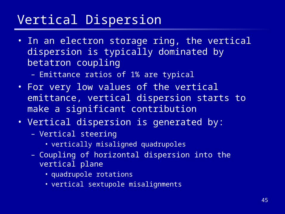
Vertical Dispersion
• In an electron storage ring, the vertical dispersion is typically dominated by betatron coupling– Emittance ratios of 1% are typical
• For very low values of the vertical emittance, vertical dispersion starts to make a significant contribution
• Vertical dispersion is generated by:– Vertical steering
• vertically misaligned quadrupoles
– Coupling of horizontal dispersion into the vertical plane• quadrupole rotations
• vertical sextupole misalignments

46
Vertical Steering: Closed Orbit Distortion
• A quadrupole misalignment can be represented by a kick that leads to a “cusp” in the closed orbit
• We can write a condition for the closed orbit in the presence of the kick:
• We can solve to find the distortion resulting from many kicks:
xxxxx
xxxxx
sincossin
sinsincosM
0
0
0
0
y
y
y
yM
ssss
sssy yyy
y
y
yd cos
sin2 1
1
1
47
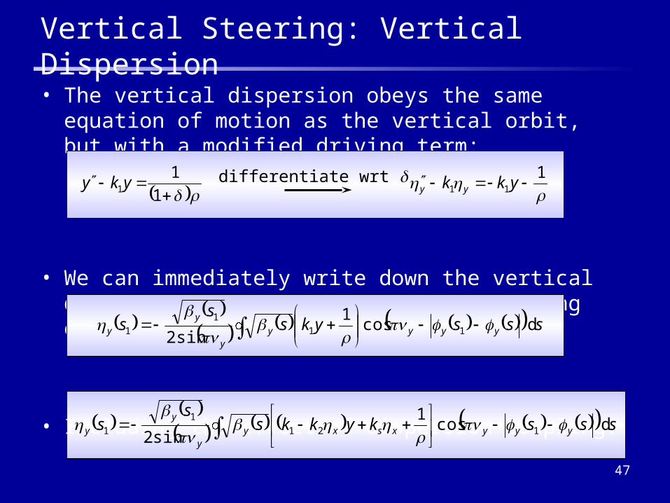
• The vertical dispersion obeys the same equation of motion as the vertical orbit, but with a modified driving term:
• We can immediately write down the vertical dispersion arising from a set of steering errors:
• Including the effect of dispersion coupling:
Vertical Steering: Vertical Dispersion
1
11 yky
1
11 ykk yydifferentiate wrt
sssyks
ss yyyy
y
y
y d cos1
sin2 11
1
1
ssskykks
ss yyyxsxy
y
y
y d cos1
sin2 121
1
1
48
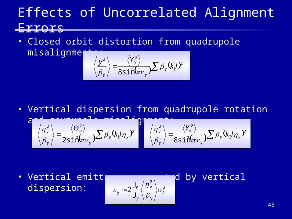
Effects of Uncorrelated Alignment Errors
• Closed orbit distortion from quadrupole misalignments:
• Vertical dispersion from quadrupole rotation and sextupole misalignment:
• Vertical emittance generated by vertical dispersion:
212
22
sin8lk
Yyy
y
q
y
212
22
sin2 xyy
q
y
y lk
2
22
22
sin8 xyy
s
y
y lkY
22
y
2y
JJ
y
Ey

49
Examples of Alignment Sensitivities
• Note:Sensitivity values give the random misalignments that will generate a specified vertical emittance. In practice, coupling correction schemes mean that significantly larger misalignments can be tolerated.
APS SLSKEK-ATF
ALS NLC MDR TESLA DR
Energy [GeV] 7 2.4 1.3 1.9 1.98 5
Circumference [m] 1000 288 140 200 300 17,000
γεx [µm] 34 23 2.8 24 3 8
γεy [nm] 140 70 28 20 19 14
Sextupole vertical [µm] 74 71 87 30 53 11
Quadrupole roll [µrad] 240 374 1475 200 511 38
Quadrupole jitter [nm] 280 230 320 230 264 76
50
Collective Effects
• Issues of damping, acceptance, coupling are all single particle effects - they are independent of the beam current
• Particles in a storage ring interact with each other (directly or via some intermediary e.g. the vacuum chamber)
• A wide variety of collective effects limit the achievable beam quality, depending on the bunch charge or total current
• The consequences of collective effects are– Phase space distortion and/or emittance growth
– Particle loss
• Damping rings have high bunch charges, moderate energies and small emittance– Vulnerable to a wide range of collective effects
• Too wide a subject to enter into here!