linear devices corporation - flakwebserver.flak.no/vbilder/20700_i.pdf · manufactured by linear...
TRANSCRIPT

Linear Devices Corporation
Electromechanical Trim Tab Systems
• Product Description • Installation
• Operation • Retrofitting
Lit #D2805 Revised 4/28/05
Linear Devices Corporation, 8790 Park Central Drive, Richmond, VA, 23227, U.S.A.

TABLE OF CONTENTS
Introduction………………………………..………….……………..3
Product Description………….………………..………………….….4
Installation…………………..……………………………….………6
Tools………..………….………………………………..….…..6 Tabs………..…………………………………………….……..6
Actuators………………..………………………………….…..6 Controls, and Manual Switches…….…………………………..8 Operational Checkout….……………………………………...10
Operation……………………………….…………………………...10
Retrofitting……….…………………….…………………………...11
Troubleshooting……….………………..…………………………..12
Specifications…….……………………..…………………………..14
Safety Information………………..…….…………………………..14
2

INTRODUCTION
Thanks for your interest in the Lectrotab, non-hydraulic marine trim tab product. We developed this non-hydraulic, electromechanical product in order to avoid the disadvantages inherent with the hydraulic approach. The Lectrotab design advantages include: • A tab actuator design which contains all of the actuating assembly
within its own housing so there is nothing to install inside the boat. • A non-hydraulic design which can’t leak oil-because there is none. • Convenient helm mounted control switches which provide instant
actuator start and stop for very accurate actuator positioning. • A full pivoting upper bracket for maximum installation flexibility. • A patented ram seal which cannot be fouled by barnacle growth
and a patented internal pressurization system for added watertight integrity.
• A complete non-metallic external structure which cannot corrode and will not deteriorate in the sun or under water.
The Lectrotab installation is quick and saves space. And with an actuating force exceeding 700 pounds, your tabs are promptly positioned where you want them, - and they stay put. Enjoy!
3

PRODUCT DESCRIPTION
Pleasure Boat Trim Tabs 2 ¼ “ (57 mm) Stroke, 12 or 24 VDC
4 or 8 Second Stroke Time Planing boats typically need a way to adjust, while under way, port or starboard list and/or high planing angle, wherein the bow rides high, resulting in limited operator visibility and decreased operating efficiency. The Lectrotab marine trim tab system for powerboats, manufactured by Linear Devices Corporation, addresses these needs. Lectrotab is a non-hydraulic, electromechanical system, which, except for the control switches, has no components inside the boat. With an actuating force of 700 pounds when pushing, and 100 pounds when retracting, the Lectrotab actuator, in the conventional manner, deploys trim tabs, hinged at the rear of a planing hull, to control the boat’s planing angle and planing efficiency. Typically, a boat will use two tab/actuator assemblies, one to port and one to starboard. As standard, tabs are offered in 9” and 12” chords (chord is the tab length from the hinge aft end) and in widths from 9” to 42”, in 12 gage, 304 series stainless steel. Other sizes, materials and custom shapes are also available. The two-piece tab employs a standard hinge and pin design with no welded joints. Wider tabs may use two actuators per tab. Consult Lectrotab Application Engineering for such applications. Lectrotab is controlled by dual rocker switches which serve to start, stop and reverse the actuator motor in order to extend, stop or retract the tabs. Both controls are specially designed to provide and “instant stop” circuit when the switches are released, thus preventing actuator over-run. Tabs can be controlled simultaneously, independently, or cross-controlled (simultaneously moving one tab up and the other tab down). While the tabs and controls are conventional, the Lectrotab actuator, which is the heart of the system, is unique. Sealed inside each actuator is an electric motor and reduction gear which provides high torque power to a “worm” screw which moves the actuator ram in or out to move the tab up or down. The actuator, which requires no maintenance, is pre-lubricated and completely sealed in a non-metallic case which cannot corrode. The “worm” is actually a very special ball bearing device, which, at the end of it’s stroke, stops it’s linear motion but continues to turn freely, thus eliminating the need for electrical limit switches inside the actuator housing. The Lectrotab conventional control assembly is a 3 1/8” x 3 1/4“ panel (79mm x 83mm) with two rocker type switches, of the conventional low profile type, or of a specially designed high profile or lever type. The high profile design is convenient to operate by “feel” when the switches are located, for example, on the vertical face of a console where they are protected from the elements but not easy to see. Also, Lectrotab switches are available separately for custom mounting. For retrofit, the Lectrotab actuator is designed to directly replace the most popular hydraulic type and in the process, eliminate the associated hydraulic pump, reservoir and connecting tubing. The hydraulic system control switches however, MUST also be replaced with Lectrotab control switches since the Lectrotab electrical circuit is quite different.
4
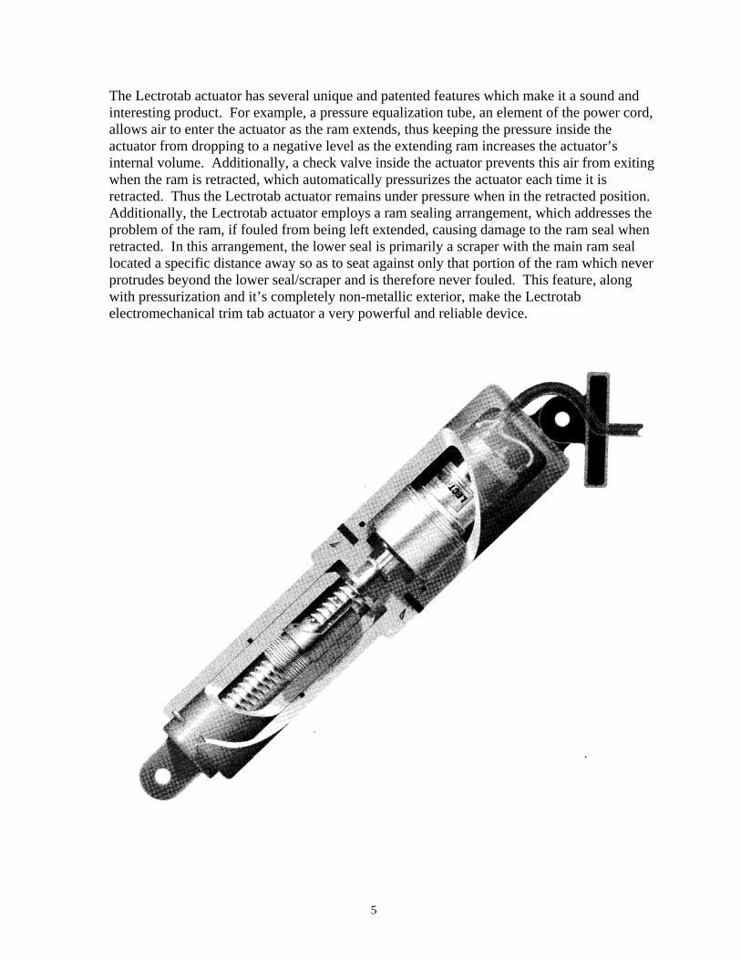
The Lectrotab actuator has several unique and patented features which make it a sound and interesting product. For example, a pressure equalization tube, an element of the power cord, allows air to enter the actuator as the ram extends, thus keeping the pressure inside the actuator from dropping to a negative level as the extending ram increases the actuator’s internal volume. Additionally, a check valve inside the actuator prevents this air from exiting when the ram is retracted, which automatically pressurizes the actuator each time it is retracted. Thus the Lectrotab actuator remains under pressure when in the retracted position. Additionally, the Lectrotab actuator employs a ram sealing arrangement, which addresses the problem of the ram, if fouled from being left extended, causing damage to the ram seal when retracted. In this arrangement, the lower seal is primarily a scraper with the main ram seal located a specific distance away so as to seat against only that portion of the ram which never protrudes beyond the lower seal/scraper and is therefore never fouled. This feature, along with pressurization and it’s completely non-metallic exterior, make the Lectrotab electromechanical trim tab actuator a very powerful and reliable device.
5

INSTALLATION
TOOLS: Ordinary hand tools, mechanical and electrical, marine sealant, drill bits and #12 x 1-1/4” stainless steel screws.
TABS: The tabs are designed to be secured to the transom, or in an underhull pocket at or near the transom. If attachment to the transom is planned, the lower surface of the tab is ideally placed ½” (12mm) ABOVE the lower surface of the hull; see figure 1. If the tab is mounted lower, water will spray up through the hinge slot which may or may not be desirable. For example, with a swim platform such spray may not be a factor.
The lateral location of the tab typically favors outboard placement, since the further outboard, the more effective the tab will be at a given amount of deflection when correcting list. However, several inches inboard may be needed to protect the tab from being hit if the boat sideswipes a piling-typically 2” (5.1 cm); see figure 2. Keep the inboard end of the tab at least 6” (15cm) away from outdrive and outboard motor apparatus.
Once the tab placement point has been determined, make sure there are no difficulties with the transom structure which could preclude fastening the tabs in that position. Fasten the tabs to the transom with appropriate screws or thru-bolts. ACTUATORS: The actuator is normally supplied with the lower bracket pinned to the ram and the upper bracket loosely bolted in place at the top of the actuator. Begin the actuator installation by placing the lower bracket over the two studs on the tab and securing the bracket with the two ¼-20 self locking nuts found on the studs. Torque until snug; about 60 inch pounds. On the upper bracket, punch out the 3 outermost screw holes. The three innermost holes match the Bennett style upper bracket hole pattern and are used for retrofits. Place the actuator upper bracket against the transom so that the tab is parallel to the
6

bottom of the boat, or up as much as ¼” per figure 3, and vertically aligned per figure 4. Mark the 3 holes, swing the actuator and bracket away from the transom and drill holes as appropriate for the fasteners to be used.
WARNING Do not drill the upper bracket holes using the upper bracket as a template while it is connected to the actuator. Doing so has resulted in the side of the drill bit cutting through the actuator wire, resulting in a fatal water leak through this breach of the wire into the actuator. For about an inch along the wire as it exits the actuator, there is a length of shrink wrap to help protect the wire from careless drilling, however, carelessness with the drill or screwdriver can still cause damage to the wire. Please be careful! Rotate the actuator clockwise, as viewed from the top, several turns to ensure it is fully retracted. When fully retracted, the ram extends out of the housing, zero to 1/16”. Once the ram is fully retracted, additional turning will not retract it further.
IMPORTANT Before proceeding to fasten the upper bracket to the transom, a decision must be made as to whether or not the actuator power wire will be routed through the upper bracket and then
through the transom or through the transom at another location. WIRE THROUGH THE BRACKET: To utilize this option, drill an 11/32” (9mm) hole through the transom, with it’s center 1 ¼“ (3.2 cm) directly below the center of the upper, outermost screw hole previously drilled. Route the actuator wire through the hole in the center of the bracket leaving a little slack as the wire passes along the groove at the top of the bolt boss. Fill the cavity on the back of the bracket, around the wire, with sealer. Route the wire through the transom and secure the bracket with the screws supplied. Tighten the upper bracket bolt until snug. Do not over-tighten since the actuator must be free to rotate in the bracket. Both actuators are installed in the same way. WIRE THROUGH THE TRANSOM: Without routing the wire through the upper bracket, mount the upper bracket to the transom with sealer around the (3) screw holes. Tighten the upper bracket bolt until snug. Do not over-tighten. At the chosen entry point on the transom, drill an 11/32” (9mm) hole and pass the wire through. After securing the wire appropriately, apply sealer to the wire at the entry point and cover it with a clamshell or other suitable device. Both actuators are installed in the same manner.
7
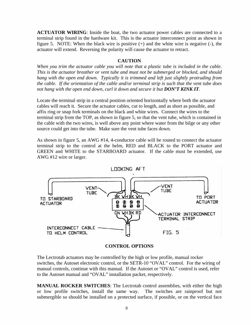
ACTUATOR WIRING: Inside the boat, the two actuator power cables are connected to a terminal strip found in the hardware kit. This is the actuator interconnect point as shown in figure 5. NOTE: When the black wire is positive (+) and the white wire is negative (-), the actuator will extend. Reversing the polarity will cause the actuator to retract.
CAUTION When you trim the actuator cable you will note that a plastic tube is included in the cable. This is the actuator breather or vent tube and must not be submerged or blocked, and should hang with the open end down. Typically it is trimmed and left just slightly protruding from the cable. If the orientation of the cable and/or terminal strip is such that the vent tube does not hang with the open end down, curl it down and secure it but DON’T KINK IT. Locate the terminal strip in a central position oriented horizontally where both the actuator cables will reach it. Secure the actuator cables, cut to length, and as short as possible, and affix ring or snap fork terminals on the black and white wires. Connect the wires to the terminal strip from the TOP, as shown in figure 5, so that the vent tube, which is contained in the cable with the two wires, is well above any point where water from the bilge or any other source could get into the tube. Make sure the vent tube faces down. As shown in figure 5, an AWG #14, 4-conductor cable will be routed to connect the actuator terminal strip to the control at the helm, RED and BLACK to the PORT actuator and GREEN and WHITE to the STARBOARD actuator. If the cable must be extended, use AWG #12 wire or larger.
CONTROL OPTIONS The Lectrotab actuators may be controlled by the high or low profile, manual rocker switches, the Autoset electronic control, or the SETR-10 “OVAL” control. For the wiring of manual controls, continue with this manual. If the Autoset or “OVAL” control is used, refer to the Autoset manual and “OVAL” installation packet, respectively. MANUAL ROCKER SWITCHES: The Lectrotab control assemblies, with either the high or low profile switches, install the same way. The switches are rainproof but not submergible so should be installed on a protected surface, if possible, or on the vertical face
8

of the console. For vertical face installations, the model SAB control, with the high profile switch handle, is a good choice since it's easy to use without having to see it. The outside dimensions of the control are 3 1/8" (7.9cm) wide x 3 1/4" (8.3cm) high, and the panel cutout is 2 1/4” (5.7cm) x 2” (5.1cm). The control is fastened with (4) #6 fillister head screws which are included in the hardware kit. Connected to the back of the control is a RED and BLACK wire pair which is to be connected to the boat's power through a breaker or through a slow blow fuse and ON/OFF switch, RED to positive (+) and BLACK to negative (-); See figure 6. Do not power the tabs from the boat's ignition switch; go directly to the boat's D.C. panel. Typically the ignition switch circuit may not handle sufficient amperage for both tabs to operate simultaneously under heavy load. Also, on the back of the control, at the center of each of the two switches, are a total of four push-on terminals to which the four wires from the interconnect terminal strip will connect. See figure 6.
NOTE The 4-conductor cable supplied by Lectrotab is made up of 4 AWG #14 conductors in Black, White, Red and Green. One end is supplied with push-on terminals meant to be connected to the control, per figure 6. The other end is meant to be cut to length or extended, fitted with ring or snap fork terminals and connected to the interconnect terminal strip per figure 5.
CAUTION
Single station rocker switch controls are designated SAF-S or SAB-S. The “-S” is for “shorting”. When the switch is released, these shorting type switches provide instant stop action at the actuators which results in very accurate positioning. However, the “-S” control cannot be used as dual controls. If dual controls are needed, the “-NS” models SAF-NS and SAB-NS controls must be used to avoid a short circuit in the system. The instant stop feature, however, cannot be included in the “-NS” controls.
9

OPERATIONAL CHECKOUT: 1. Energize the power to the control. 2. With someone observing the tabs, press the upper end of the left rocker switch for
“bow down”. The right or starboard tab should move downward. Press the lower end of the left rocker switch to retract the starboard tab.
3. Press the right rocker switch for “bow down”. The left or port tab should move
downward. Press the lower end of the right rocker switch to retract the port tab. 4. Checkout is now complete.
OPERATION The Lectrotab control consists of two momentary rocker switches, oriented fore and aft, which individually control the two tab actuators. The forward edge of the control plate is marked BOW DOWN. Pushing the rocker switches TOGETHER, for BOW DOWN, will deploy both tabs downward, resulting in lift at the stern and a lowering of the bow or planing angle. Pushing the rocker switches together, the other way, will retract both tabs, resulting in raising the bow. Pushing the right hand switch for BOW DOWN, will cause the left tab to deploy and the starboard (right) side of the boat to dip. Pushing the left-hand switch for BOW DOWN will cause the right tab to deploy and the port (left) side of the boat to dip. Until you are familiar with how your boat will react to your Lectrotab system, even if you have previously operated your boat with other types, begin as follows. 1. In reasonably calm water, with the tabs retracted, bring your boat onto a plane, then
add just enough additional power to maintain a stable "on top" feel. 2. Simultaneously push BOTH switches to the BOW DOWN position for 1 second and
then observe the boat's reaction. WARNING
At this time, you must be comfortable with the reaction of the boat to the first 1-second deployment of the tabs. If you are not comfortable, retract the tabs and seek advice and/or assistance. If you are comfortable, proceed as follows, but only to the extent that you continue to feel comfortable with deploying the tabs, and that you are sure the boat is behaving predictably. 3. With no change in power, observe the engine RPM and boat speed and continue to
deploy the tabs in 1 second increments until either RPM or speed is stabilized at it's peak value. Now observe if the boat lists to port or starboard. If so, incrementally RETRACT the appropriate tab so as to correct the list. This point is the optimum tab setting for your boat at this speed, in this sea and at this load. As conditions vary, tab deployment will also vary but can be optimally adjusted in this same manner.
10

4. To slow down, most boats will be more stable if the tabs are retracted first, which will allow the bow to rise and then fall as power is reduced. However, if the tabs are sustaining a significant bow down correction, the high bow up, as result of retracting the tabs before reducing power, may make the boat less than stable and may restrict visibility. In this case you can reduce power before retracting the tabs or you can reduce power and retract the tabs simultaneously as appropriate.
5. At slow speed, make it a habit to always retract the trim tabs. Operating around
docks or operating in reverse is more likely to result in tab and or actuator damage if the tabs are down. Also, if the tabs are left down, sea growth may accumulate on the extended portion of the ram. This fouling is undesirable but fortunately is easily avoided by always retracting the tabs when they are not needed.
COMMENT
Invariably, boats will be left moored with the tabs down and growth will foul the ram. However, by design, the Lectrotab seal system addresses this by employing a patented scrapper/seal arrangement, which will effectively deal with the problem. But it's still good practice to keep the tabs up when not in use.
RETROFITTING
The Lectrotab actuator, the actuator upper bracket and the control switches, will directly replace the 12” Bennett style hydraulic actuator, control switches and all hydraulic components. This retrofit will continue to use the Bennett style tab, lower bracket and pin. Proceed as follows: 1. Remove the nylon shear pin that connects the hydraulic cylinder to the lower bracket. Leave the tab and lower bracket in place and use them with the Lectrotab actuator. Keep the pin. 2. Remove the hydraulic cylinder by removing the three screws and the hydraulic supply line. Discard the actuator, all of the associated hydraulic components and the control switches. Keep the (3) screws 3. Remove the upper bracket from the Lectrotab actuator. With a Phillips screwdriver, punch out the (3) innermost screw holes if you wish to use the (3) existing transom screw holes where the hydraulic cylinder was attached. If these screw holes are not useable, punch out the three outermost screw holes in the bracket and make new holes in the transom. 4. Now, route the Lectrotab power cord through the Lectrotab upper bracket and then through the former hydraulic oil line hole in the transom and get ready to secure the Lectrotab upper bracket to the transom with the original screws in the original holes or in the new holes. However, before securing, position the bracket, actuator and wire so they fit comfortably together. Using sealer around the screws and wire, push the wire through the transom until the upper bracket is against the transom and ready to secure in place.
11
CAUTION
Before inserting and tightening the upper screw, keep the wire out of the way of the screwdriver so you don't damage it while tightening the screw. The actuator, being loose from the bracket will also be handy while installing the other two screws. 5. Fasten the upper bracket in place. 6. Reassemble the Lectrotab upper bracket to the Lectrotab actuator with the 5/16"-18
bolt and nut. Torque until snug but do not over tighten. 7. Using the original shear pin, attach the Lectrotab lower end to the original bracket
and tab assembly. 8. Wire the Lectrotab system in accordance with the wiring diagrams on pages 6 and 7.
CAUTION
Rocker switches supplied with hydraulic trim tabs are electrically different and are not compatible with the Lectrotab product. Do not use any other type switches with the Lectrotab product except those supplied by Lectrotab.
NOTE
When installed as a retrofit, the Lectrotab actuator retracted and extended length will be exactly the same as the 12” Bennett style actuator retracted and extended length.
TROUBLESHOOTING
PROBLEM: Circuit breaker trips or fuse blows instantly when the power is turned on. 1. Dual station controls are installed using the shorting type switches with control and
switch models ending in “-S”. Both controls and switches must be changed to the non- shorting type with model numbers ending in “-NS”. “-S” types are used for single stations only.
2. Something is shorting the power input wires at the back of the control. PROBLEM: Neither actuator operates. 1. Confirm D.C. Voltage (12 or 24 as appropriate) at the black and red power input wires at
the back of the control. See figure 6. 2. Confirm D.C. Voltage at the actuator interconnect terminal strip as follows. See figure 5.
12

Switch Position Voltage at terminal strip
Neutral: Green (Dead) White (Dead) Black (Dead) Red(Dead) Left Bow Down: Green (+) White (-) Black (Dead) Red(Dead)
Left Bow Up: Green (-) White (+) Black (Dead) Red(Dead) Right Bow Down: Green (Dead) White (Dead) Black (+) Red (-)
Right Bow Up: Green (Dead) White (Dead) Black (-) Red (+)
3. Confirm actuator motor resistance by removing the black actuator wire, and checking
black to white; 1 to 3 ohms for 12 Volt models and 4 to 6 ohms for 24 Volt models. An open circuit or short is an internally faulty actuator. Replace the actuator.
4. If all electrical checks are OK, the actuator has an internal mechanical fault. Replace the
actuator.
13

SPECIFICATIONS All controls, bare control switches and actuators have identification numbers. The tabs, which are identified by length (chord) and width do not have identification numbers. MODEL DESCRIPTION * SAF-S Flat Rocker Profile, DPDT with common terminals shorted in neutral. * SAB-S Bat Handle Profile, DPDT with common terminals shorted in neutral. ** SAF-NS Flat Profile, DPDT with common terminals not shorted in neutral. ** SAB-NS Bat Handle Profile, DPDT with common terminals not shorted in neutral. *** A Actuator, 12VDC, 8 second stroke time. *** B Actuator, 24VDC, 8 second stroke time. *** C Actuator, 12VDC, 4 second stroke time. *** D Actuator, 24VDC, 4 second stroke time. * Use in all single station installations to provide instant stop actuator action. ** Use in all dual station installations to prevent the dual controls from shorting each other. The instant stop feature is lost. *** The first of (4) characters stamped in the upper side of the actuator is the actuator model.
The following three characters are the date code. A through M (I is not used) is for January through December and the last (2) characters denote the year.
SAFETY 1. Use trim tabs cautiously and deliberately but never aggressively. Trim tab adjustment
should always FOLLOW the reaction of the boat. 2. Retract the tabs when off plane or operating in a following sea. 3. Do not use trim tabs to support one side of the hull in a tight turn. If the tab fails
under this condition, the resulting roll could render the boat uncontrollable. If you have an operating question, please call Lectrotab; toll free, at 888-LECTROTAB. We will be pleased to hear from you.
14

Linear Devices Corporation Lectrotab Trim Tabs
8790 Park Central Drive, Richmond, VA 23227, U.S.A. Phone: 804 261-3888 Fax: 804 264-3070
Toll Free: 888-LECTROTAB (532-8768) e-mail: [email protected] Visit our web site at www.lectrotab.com
15