linear motion control solutions cten
DESCRIPTION
Linear Motion ControlTRANSCRIPT

TM
&&LINEAR MOTION CONTROL SOLUTIONSLINEAR MOTION CONTROL SOLUTIONS
SYSTEMS, SLIDES & STAGES• Pre-engineered, pre-assembled, ready to install• The most complete product line available
LINEAR GUIDES• Ball, roller, and sliding friction
bearing technology• ProfileRail™ and RoundRail™ linear guides
MOTION CONTROL• Easy to Specify;
Complete Solutions • Easy to Install; Plug & Play
To place an order call:
North America: 1-800-554-THOMSONEurope: (44) 1271 334 500
Elsewhere: 516-883-8000
www.thomsonindustries.com
THOMSON INDUSTRIES, INC.
Engineering Guide for Linear Guides, Systems, Slides & Stages and Motion ControlEngineering Guide for Linear Guides, Systems, Slides & Stages and Motion Control
andand

For Application Engineering assistance contact the Thomson Technical HelpLine at 1-800-554-8466.* Trademark of Thomson Industries, Inc. THOMSON is registered in the U.S. Patent and Trademark Office and in other countries.
Linear Guid
esS
ystems, S
lides, and
Stag
esM
otio
n Co
ntrol
Page 1
PART NUMBER INDEX
Part Number Index (Alphabetical)
PartNumber PagePrefix Description Number
1AA Single Race Unsupported Linear Guide 98
1AB Double Race Unsupported Linear Guide 100
1AC Unsupported Linear Guide with Carriage 102
1BA Single Race End Supported Linear Guide 110
1BB Double Race End Supported Linear Guide 112
1BC End Supported Linear Guide with Carriage 114
1CA Single Race Continuously Supported Linear Guide 62
1CB Double Race Continuously Supported Linear Guide 64
1CC Continuously Supported Linear Guide with Carriage 66
1DA Single Race Side Mounted Linear Guide 76
1DB Double Race Side Mounted Linear Guide 78
1DC Side Mounted Linear Guide with Carriage 80
1FA Single Race Smart Rail* Linear Guide 124
1FB Double Race Smart Rail Linear Guide 126
1FC Smart Rail Linear Guide with Carriage 128
1GA Single Race Bolt from Bottom Linear Guide 84
1GB Double Race Bolt from Bottom Linear Guide 86
1GC Bolt from Bottom Linear Guide with Carriage 88
1MA Single Race Unsupported Linear Guide (metric) 104
1MB Double Race Unsupported Linear Guide (metric) 106
1MC Unsupported Linear Guide with Carriage (metric) 108
1NA Single Race End Supported Linear Guide (metric) 116
1NB Double Race End Supported Linear Guide (metric) 118
1NC End Supported Linear Guide with Carriage (metric) 120
1PA Single Race Continuously Supported Linear Guide (metric) 68
1PB Double Race Continuously Supported Linear Guide (metric) 70
1PC Continuously Supported Linear Guide with Carriage (metric) 72
1QA Single Race Smart Rail Linear Guide (metric) 130
1QB Double Race Smart Rail Linear Guide (metric) 132
1QC Smart Rail Linear Guide with Carriage (metric) 134
1RA Single Race Bolt from Bottom Linear Guide (metric) 90
1RB Double Race Bolt from Bottom Linear Guide (metric) 92
1RC Bolt from Bottom Linear Guide with Carriage (metric) 94
1VA Single Race Unsupported Corrosion Resistant Linear Guide 42
1VA Single Race End Supported Corrosion Resistant Linear Guide 48
1VA Single Race Continuously Supported Corrosion Resistant Linear Guide 54
1VB Double Race Unsupported Corrosion Resistant Linear Guide 44
1VB Double Race End Supported Corrosion Resistant Linear Guide 50
1VB Double Race Continuously Supported Corrosion Resistant Linear Guide 56
1VC Unsupported Corrosion Resistant Linear Guide with Carriage 46
1VC End Supported Corrosion Resistant Linear Guide with Carriage 52
1VC Continuously Supported Corrosion Resistant Linear Guide with Carriage 58
1WA RoundWay* Bolt from Bottom Linear Guide-Single Type 138
1WA RoundWay Bolt from Bottom Linear Guide-Dual Type 140
2AA Double Race End Supported Quickslide* Linear Guide with Carriage 168
2AB Ball Screw Actuated Double Race End Supported Superslide* System 224
Part Number Index (Alphabetical)
PartNumber PagePrefix Description Number
2BA Twin Shaft Quickslide* Linear Guide 154
2BB Twin Shaft Superslide* Linear Motion System 226
2CA Twin Shaft Web QuickSlide Linear Guide 160
2CB Twin Shaft Web Superslide Linear Motion System 228
2DA Dual Shaft Rail QuickSlide Linear Guide 146
2DA Dual Shaft Rail QuickSlide with Manual Brake 294
2DB Dual Shaft Rail SuperSlide Linear Motion System 230
2DB Dual Shaft Rail SuperSlide Linear Motion System (metric) 258
2EA Double Race Continuous Support Linear Guide 172
2EB Double Race Continuous Support SuperSlide Linear Motion System 234
2GE Turbo Module* Belt Driven Linear Motion System 284
2HB AccuSlide Ball Screw Driven Linear Motion System 260
2HE AccuSlide Belt Driven Linear Motion System 274
2NB End Supported SuperSlide Ball Screw Driven Linear Motion System 256
2NE End Supported SuperSlide Belt Driven Linear Motion System 272
2RB Continuous Support SuperSlide Ball Screw Driven Linear Motion System 262
2RE Continuous Support SuperSlide Belt Driven Linear Motion System 276
AT AccuGlide* T-Series* Linear Guide 35
AP AXI-PAK* Motion Control Package 397
APi AXI-PAK* Motion Control Package with Indexing 401
ASC Aluminum Shroud Cover 302
BEL Bellows Way Covers 74,122, 152, 166, 170, 174, 291
BLX Brushless Servo Motors 431
BSA Ball Screw Assemblies 236
CD AccuGlide* Linear Guide (Miniature Series Carriage) 29
CG AccuGlide Linear Guide (Standard Carriage) 17
CM AccuMax* Linear Guide (Carriage) 11
HW Handwheels 308
LSP Limit Switch Package (for Metric Size Systems) 296
MAB Motor Adaptor Blocks 289
MC Motor Couplings 288
MS MicroStage* Linear Guide 175
MS Micro Stage Actuated Linear Motion System 245
OD OMNIDRIVE* Digital Servo Drive (Full Size) 417
ODM OMNIDRIVE Digital Servo Drive (Mini Size) 416
RADMO Radial Mount Ball Screw Shaft Extenders 292
RD AccuGlide Linear Guide (Miniature Series Rail) 29
RG AccuGlide Linear Guide (Standard Rail) 17
RM AccuMax Linear Guide (Rail) 11
RMC Radial Mount Couplings 293
TBC7 Electric Brake Controller 306
TEB Spring Set Electric Brakes 304
TMC TMC 2000 Motion Controller 385
TNUT Tee Nut Mounting Hardware 308
TP Touch Pad 411

Line
ar G
uid
es
Page 2
AccuMax* Linear GuidePage11
AccuGlide* Linear GuidePage17
Continuous Support Linear GuidePage61
AccuGlide (Mini) Linear GuidePage29
T-Series* Linear GuidePage35
LINEAR GUIDE NUMBER 1Extremely High Rigidity, High Accuracy• Dynamic Load Capacity: up to 40,700 lbf per carriage• Maximum Speed: 6.5 ft/sec• Maximum Acceleration: 5g• Mounting: continuously supported, dual rail
LINEAR GUIDE NUMBER 2High Rigidity, Industry Standard Envelope• Dynamic Load Capacity: up to 21,800 lbf per carriage• Maximum Speed: 10 ft/sec• Maximum Acceleration: 5g• Mounting: continuously supported, single or dual rail
LINEAR GUIDE NUMBER 3Low Profile, Compact Design• Dynamic Load Capacity: up to 2,700 lbf per carriage• Maximum Speed: 10 ft/sec• Maximum Acceleration: 5g• Mounting: continuously supported, single or dual rail
LINEAR GUIDE NUMBER 4Low Cost, Compliant Structure, Industry Standard Envelope• Dynamic Load Capacity: up to 5,620 lbf per carriage• Maximum Speed: 10 ft/sec• Maximum Acceleration: 5g• Mounting: continuously supported, dual rail
LINEAR GUIDES PRODUCT SELECTOR
FluoroNyliner* Linear GuidePage41
Side Mounted Linear GuidePage75
Bolt From Bottom Linear GuidePage83
LINEAR GUIDE NUMBER 5Corrosive/Contaminated Environments• Dynamic Load Capacity: up to 12,000 lbf per carriage• Maximum Speed: 6.67 ft/sec‡
• Maximum Acceleration: unlimited‡
• Mounting: continuously or end supported, dual rail‡Load, speed and acceleration are dependent variables
LINEAR GUIDE NUMBER 6Fully Supported, Industry Standard Dimensions• Dynamic Load Capacity: up to 54,800 lbf per carriage• Maximum Speed: 10 ft/sec• Maximum Acceleration: 5g• Mounting: continuously supported, dual rail
LINEAR GUIDE NUMBER 7Side Mounted for Multiple Orientations• Dynamic Load Capacity: up to 2,480 lbf per carriage• Maximum Speed: 10 ft/sec• Maximum Acceleration: 5g• Mounting: continuously supported, dual rail
LINEAR GUIDE NUMBER 8Low Profile, Enhanced Sealing• Dynamic Load Capacity: up to 12,320 lbf per carriage• Maximum Speed: 10 ft/sec• Maximum Acceleration: 5g• Mounting: continuously supported, dual rail
End Support Linear GuidePage97
Smart Rail* Linear GuidePage123
LINEAR GUIDE NUMBER 9End Supported, Industry Standard Dimension• Dynamic Load Capacity: up to 12,320 lbf per carriage• Maximum Speed: 10 ft/sec• Maximum Acceleration: 5g• Mounting: end supported, dual rail
LINEAR GUIDE NUMBER 10Low Profile, Easy to Install• Dynamic Load Capacity: up to 12,320 lbf per carriage• Maximum Speed: 10 ft/sec• Maximum Acceleration: 5g• Mounting: continuously supported, dual rail
For Application Engineering assistance contact the Thomson Technical HelpLine at 1-800-554-8466.* Trademark of Thomson Industries, Inc. THOMSON is registered in the U.S. Patent and Trademark Office and in other countries.

Linear Guid
es
Page 3For Application Engineering assistance contact the Thomson Technical HelpLine at 1-800-554-8466.
* Trademark of Thomson Industries, Inc. THOMSON is registered in the U.S. Patent and Trademark Office and in other countries.
LINEAR GUIDES PRODUCT SELECTOR
RoundWay* Linear GuidePage137
Dual Shaft Rail* Linear GuidePage145
LINEAR GUIDE NUMBER 11Contaminated Environments, High Shock Loads• Dynamic Load Capacity: up to 70,000 lbf per carriage• Maximum Speed: 100 ft/sec• Maximum Acceleration: 14g• Mounting: continuously supported, dual rail
LINEAR GUIDE NUMBER 12Unpack and Install• Dynamic Load Capacity: up to 2,480 lbf per carriage• Maximum Speed: 10 ft/sec• Maximum Acceleration: 5g• Mounting: continuously supported, single axis assembly
Twin Shaft* Linear GuidePage153
LINEAR GUIDE NUMBER 13Unpack and Install• Dynamic Load Capacity: up to 50 lbf per carriage• Maximum Speed: 10 ft/sec• Maximum Acceleration: 5g• Mounting: end supported, single axis assembly
New Linear Guides and Accessories
E-Series• 1-piece, low cost, shaft rail assembly for sliding
contact guides
R-Series• Stainless steel miniature profile rail guides-
sizes 7, 9, and 12
Rail Covers• for profile rail products (with optional integral linear scale)
Noise Dampening Lubricants
Call Thomson Technical Helpline for technical information andproduct availability:
1-800-554-8466
Page159Twin Shaft Web* Linear Guide
Page167
LINEAR GUIDE NUMBER 15Unpack and Install• Dynamic Load Capacity: up to 12,320 lbf per carriage• Maximum Speed: 10 ft/sec• Maximum Acceleration: 5g• Mounting: end supported, single axis assembly
Double End Support Linear Guide
Double Continuous Support Linear GuidePage171
Installation GuidelinesPage178
LINEAR GUIDE NUMBER 16Unpack and Install• Dynamic Load Capacity: up to 12,320 lbf per carriage• Maximum Speed: 10 ft/sec• Maximum Acceleration: 5g• Mounting: continuously supported, single axis assembly
LINEAR GUIDES
Engineering SupportPage185
LINEAR GUIDES
MicroStage* Linear GuidePage175
LINEAR GUIDE NUMBER 17Unpack and Install• Dynamic Load Capacity: up to 33 lbf per carriage• Maximum Speed: 10 ft/sec• Maximum Acceleration: 5g• Mounting: continuously supported, single axis assembly
LINEAR GUIDE NUMBER 14Unpack and Install• Dynamic Load Capacity: up to 3,000 lbf per carriage• Maximum Speed: 10 ft/sec• Maximum Acceleration: 5g• Mounting: end supported, single axis assembly
COMING SOON!

Sys
tem
s, S
lides
, and
Sta
ges
Page 4For Application Engineering assistance contact the Thomson Technical HelpLine at 1-800-554-8466.
* Trademark of Thomson Industries, Inc. THOMSON is registered in the U.S. Patent and Trademark Office and in other countries.
MicroStage* MSPage245
SuperSlide* 2ABPage224
SuperSlide 2EBPage234
Twin Shaft* SuperSlide 2BBPage226
Twin Shaft Web* SuperSlide 2CBPage228
A miniature lead screw actuated double race continuouslysupported linear motion system available with:• pre-aligned LinearRace* ways• the segmented Super Ball Bushing* bearing• an integral lead screw assembly• nominal sizes of 25mm and 33mm overall heights• screw leads from .25 inch to 1.2 inch
A ball screw actuated double race end supported systemavailable with:• pre-aligned LinearRace ways• the Super Smart Ball Bushing* bearing• an integral ball screw assembly• nominal sizes from 1/2 inch to 1 1/2 inch shaft diameters• ball screw leads from .200 inch to 1.875 inch
A lead screw actuated welded double race end supportedsystem available with:• pre-aligned and welded LinearRace ways• the segmented Super Ball Bushing bearing• an integral lead screw assembly• screw leads from .100 inch to 1.00 inch• end supports for use when bridging or spanning a gap
A ball screw actuated welded double race end supportedsystem available with:• pre-aligned and welded LinearRace ways• the Super Smart Ball Bushing bearing• an integral ball screw assembly• nominal sizes in 1/2, 3/4, and 1.00 inch shaft diameters• end supports for use when bridging or spanning a gap
SYSTEMS, SLIDES, & STAGESPRODUCT SELECTOR
Dual Shaft Rail* SuperSlide 2DBPage230
Ball Screw Assemblies-Model BSAPage236
SuperSlide 2NBPage256
A ball or lead screw actuated double race continuously supported system available with:• pre-aligned and continuously supported LinearRace ways• the Super Smart Ball Bushing bearing• an integral ball screw assembly• nominal sizes in 1/2, 3/4, and 1.00 inch shaft diameters • ball screw leads from .200 inch to 1.00 inch
A ball screw actuated double race continuously supported systemavailable with:• pre-aligned and continuously supported LinearRace ways• the Super Smart Ball Bushing bearing• an integral ball screw assembly • nominal sizes from 1/2 inch to 1 1/2 inch shaft diameters• ball screw leads from .200 inch to 1.875 inch
A linear actuation system with integral end supports available with:• integral end supports for a fixed/simple mounting arrangement• angular contact thrust bearings for high axial load capacity• nominal sizes from 1/2 inch to 1 1/2 inch screw diameters• ball screw leads from .200 inch to 1.875 inch• ball nut mounting heights that adapt to appropriately
sized linear guides
A ball screw actuated double race end supported system in metricdimensions available with:• pre-aligned LinearRace ways• the Super Smart Ball Bushing bearing• an integral ball screw assembly• 20mm nominal size shaft diameter• ball screw leads from 5mm to 20mm
Dual Shaft Rail* SuperSlide 2DB - MetricPage258
SuperSlide 2RBPage262
A ball or lead screw actuated double race continuously supported system in metric dimensions available with:• pre-aligned and continuously supported LinearRace ways• the Super Smart Ball Bushing bearing• an integral ball screw assembly• nominal sizes in 1/2, 3/4, and 1.00 inch shaft diameters • 5mm ball screw lead
A ball screw actuated double race contiuously supported system in metric dimensions available with:• pre-aligned and continuously supported LinearRace ways• the Super Smart Ball Bushing bearing• an integral ball screw assembly• 12mm and 16mm nominal size shaft diameters• ball screw leads from 5mm to 20mm

System
s, Slid
es, and S
tages
Page 5
A belt driven double linear ball guide contiuously supportedsystem in metric dimensions available with:• pre-aligned and continuously supported AccuGlide
linear ball guides• an integral belt drive assembly• a NemaTRUE planetary gearhead in 4 standard ratios • 10mm and 20mm nominal size systems
For Application Engineering assistance contact the Thomson Technical HelpLine at 1-800-554-8466.* Trademark of Thomson Industries, Inc. THOMSON is registered in the U.S. Patent and Trademark Office and in other countries.
SYSTEMS, SLIDES, & STAGESPRODUCT SELECTOR
AccuSlide* 2HBPage260
SuperSlide 2NEPage272
A ball screw actuated double linear ball guide contiuouslysupported system in metric dimensions available with:• pre-aligned and continuously supported AccuGlide* linear ball
guides• an integral ball screw assembly• 10mm and 20mm nominal size systems• ball screw leads from 5mm to 25mm
A belt driven double race end supported system in metricdimensions available with:• pre-aligned LinearRace* ways• the Super Smart Ball Bushing* bearing• an integral belt drive assembly• a NemaTRUE* planetary gearhead in 4 standard ratios• 20mm nominal size shaft diameter
SuperSlide 2REPage276
A belt driven double race contiuously supported system inmetric dimensions available with:• pre-aligned and continuously supported LinearRace ways• the Super Smart Ball Bushing bearing• an integral belt drive assembly• a NemaTRUE* planetary gearhead in 4 standard ratios • 12mm and 16mm nominal size shaft diameters
Page274AccuSlide 2HE
Page284Turbo Module* 2GE
AccessoriesPage287
Engineering Support-InchPage310
• motor couplings and motor adaptor blocks• protective bellows• radial mount ball screw shaft extender• QuickSlide* with manual brake• limit switch packages• TEB spring set brakes• TBC7 brake controller• Hand wheels• T-nuts
SuperSlide ball screw actuated systemsInch sizeSystem selection requirements
Engineering Support-MetricPage327
SuperSlide ball screw actuated systemsMetric sizeSystem selection requirements
Engineering Support-MetricPage342
SuperSlide belt actuated systemsMetric sizeSystem selection requirements
Engineering Support-MetricPage359
Turbo module belt actuated systemsMetric sizeSystem selection requirements
A belt driven single linear ball guide system for heavy duty overhung load or gantry applications available with:• a base assembly that is designed to be its own support structure• pre-aligned and continuously supported AccuGlide
linear ball guides• an integral belt drive assembly• an AccuTRUE* planetary gearhead in 3 standard ratios

Page 6For Application Engineering assistance contact the Thomson Technical HelpLine at 1-800-554-8466.
* Trademark of Thomson Industries, Inc. THOMSON is registered in the U.S. Patent and Trademark Office and in other countries.
TMC 2000 MOTION CONTROLLERPage385
Page397
OMNIDRIVE Digital Servo DrivesPage413
BLX Brushless Servo MotorsPage431
• High performance, stand alone, multi axis servo and stepper motor controller• Performs point to point motion, linear and circular interpolation, contouring, electronic gearing, electronic cam,
and jogging• Powerful yet simple instruction set supports multitasking, user variables and arrays, arithmetic and
logic functions, position latch, event triggers, error handling and more.• Servo Setup Kit* software for Windows® provides communications, program editing,
tuning and diagnostics• All optoisolated I/O
• A complete servo axis that operates either with a motion controller or as a smart stand alone drive• Includes a matched BLX brushless motor, OMNIDRIVE* digital servo drive, professionally molded cables,
OMNI LINK* setup software, and documentation for a fast and worry free installation• The latest technology and most rugged design for a high performance industrial quality turn key
motion control solution
• Fully digital “smart” brushless servo amplifier with integrated power supply• Configurable for analog input, step and direction, serial link, encoder follower, electronic gearing.• Indexing option for stand alone positioning capabilities• Available in 0.5, 1, 2, 3, 7.5, and 15 kW continuous power ratings• Included OMNI LINK setup and diagnostic software
• Superior magnetic and thermal design gives exceptional performance and the highest torque per frame size • Standard IP65 sealing, MS style fluid tight connectors, oversize bearings, and thermal switch ensure a long
and worry free service life• A variety of frame sizes and winding configurations are available to suit your precise application needs• Internal bearing mounted commutating encoder provides precision and reliability• Available with planetary gearheads and internal brakes
MOTION CONTROL SOLUTION SELECTOR
AXI-PAK* Complete Servo Axis Package
www.thomsoncontrol.comCall: 1-800-554-THOMSONM
oti
on
Co
ntro
l

TM
LINEAR GUIDE SOLUTIONSLINEAR GUIDE SOLUTIONS
LINEAR GUIDES• Ball, roller, and sliding friction
bearing technology• ProfileRail* and RoundRail* linear guides
www.linearguides.com
THOMSON INDUSTRIES, INC.
Engineering Guide for Linear Guides
Page 7For Application Engineering assistance contact the Thomson Technical HelpLine at 1-800-554-8466.
* Trademark of Thomson Industries, Inc. THOMSON is registered in the U.S. Patent and Trademark Office and in other countries.
Linear Guid
es Sectio
n

Application Criteria 1 2 3 4 5 6 7 8 9 10 11 12 13 14 15 16 17
High Loads ✔ ✔ ✔ ✔ ✔ ✔ ✔ ✔ ✔ ✔
Equivalent Load in All Directions ✔ ✔ ✔ ✔
Ultra Compactness ✔ ✔ ✔ ✔
High Travel Accuracy ✔ ✔ ✔
High Rigidity ✔ ✔ ✔
Extreme Smoothness ✔ ✔ ✔ ✔ ✔ ✔ ✔ ✔ ✔ ✔ ✔ ✔
End Supported ✔ ✔✔ ✔
Single Rail ✔ ✔ ✔ ✔
Harsh Environment ✔ ✔ ✔
Low Cost Installation (multiple rail) ✔ ✔ ✔ ✔ ✔ ✔ ✔
Complete Axis Solution ✔ ✔ ✔ ✔ ✔ ✔
Page No. 11 17 29 35 41 61 75 83 97 123 137 145 153 159 167 171 175
Page 8The specifications and data in this publication are believed to be accurate and reliable. However, it is the responsibility of the product user to determine thesuitability of Thomson products for a specific application. While defective products will be replaced without charge if promptly returned, no liability is assumed beyond such replacement.
* Trademark of Thomson Industries, Inc. THOMSON is registered in the U.S. Patent and Trademark Office and in other countries.
Line
ar G
uid
es
• Smoothness of Travel
• Speed & Acceleration
• Envelope
• Environment
• Cost of Product
• Cost of Installation
• Cost of Replacement
• Load/Life
• Travel Accuracy
• Rigidity
• Machine Tools
• Packaging Machinery
• Automotive Assembly Equipment
• Semiconductor Equipment
• Medical Equipment
• Food Processing Equipment
Linear Guide Selection Criteria:
Application Selector Guide
Application Examples:
Accu
Max
*Ac
cuG
lide*
Accu
Glid
e (m
ini)
T-Se
ries*
Fluo
roNy
liner
*Co
ntin
uous
Sup
port
Side
Mou
nted
Bolt
From
Bot
tom
End
Supp
ort
Smar
tRa
il*Ro
undW
ay*
Dual
Sha
ft Ra
ilTw
in S
haft*
Twin
Sha
ft W
eb*
Doub
le E
nd S
uppo
rt Do
uble
Con
tinuo
us S
uppo
rtM
icro
Stag
e*
Linear Guide
For more information, or to place an order, please contact your local authorized Thomson distributor orThomson Industries, at 1-800-554-THOMSON, Fax: 1-800-445-0329, or E-mail at [email protected].
The specifications and data in this publication are believed to be accurate and reliable. However, it is the responsibility of the product user to determine thesuitability of Thomson products for a specific application. While defective products will be replaced without charge if promptly returned, no liability is assumed beyond such replacement.
* Trademark of Thomson Industries, Inc. THOMSON is registered in the U.S. Patent and Trademark Office and in other countries.
Linear Guid
es
Page 9
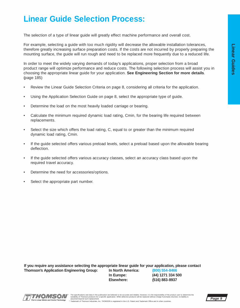
Linear Guide Selection Process:
The selection of a type of linear guide will greatly effect machine performance and overall cost.
For example, selecting a guide with too much rigidity will decrease the allowable installation tolerances,therefore greatly increasing surface preparation costs. If the costs are not incurred by properly preparing themounting surface, the guide will run rough and need to be replaced more frequently due to a reduced life.
In order to meet the widely varying demands of today’s applications, proper selection from a broad product range will optimize performance and reduce costs. The following selection process will assist you inchoosing the appropriate linear guide for your application. See Engineering Section for more details.(page 185)
• Review the Linear Guide Selection Criteria on page 8, considering all criteria for the application.
• Using the Application Selection Guide on page 8, select the appropriate type of guide.
• Determine the load on the most heavily loaded carriage or bearing.
• Calculate the minimum required dynamic load rating, Cmin, for the bearing life required between replacements.
• Select the size which offers the load rating, C, equal to or greater than the minimum required dynamic load rating, Cmin.
• If the guide selected offers various preload levels, select a preload based upon the allowable bearing deflection.
• If the guide selected offers various accuracy classes, select an accuracy class based upon the required travel accuracy.
• Determine the need for accessories/options.
• Select the appropriate part number.
If you require any assistance selecting the appropriate linear guide for your application, please contactThomson’s Application Engineering Group: In North America: (800) 554-8466
In Europe: (44) 1271 334 500Elsewhere: (516) 883-8937

THOMSON INDUSTRIES, INC.2 Channel Drive • Port Washington, NY 11050 USA
( 1 (800) 554-8466 • Fax: 1 (516) 883-9039Internet: www.thomsonindustries.com • E-mail: [email protected]
LinearFax*: 1 (800) 55-4-THOMSON • Employment Opportunities Fax: 1 (516) 883-4109
• Only Thomson offers both RoundRail* and ProfileRail* self-lubricating linear guides• Reduces system cost by eliminating the need for expensive lubrication systems• Clean, self-lubricating applicator eliminates oil-related contamination• Increases bearing life by offering enhanced protection
Contact Spring
Double Lip Seal
Oil-saturated Polymer
Trademark of Thomson Industries, Inc. THOMSON is registered in the U.S. Patent and Trademark Office and in other countries.
©1999 Thomson Industries, Inc. Printed in the U.S.A. 8-12-99 HAP 9906-08.QXD
*
DESIGN The LL option
consists of a sec-tion of oil-saturated
polymer, custom madeto fit the rail. These sec-
tions are installed on eachend, inside the double lip seal.
A proprietary spring assemblyassures continuous contact with the
rail, releasing oil as the carriage moves.This ensures a film of lubricant between
the balls and bearing races, and providesenhanced protection, maintaining long-term
running efficiency.
PERFORMANCEThomson has incorporated a proven oil-saturated
polymer used for over 10 years to lubricate radialbearings. This product has a successful track record in
applications ranging from food processing to automo-tive assembly.
The new LL Option can provide maintenance-free operation and enhancedprotection for a broad range of applications.
PATENT PENDING
All Thomson Industries Manufacturing Locations areISO 9000 Certified and Automotive Facilities
Operate to QS-9000 StandardsThree-time Winner General Motors Supplier of the Year
ISO 9000
Maintenance-FreeMaintenance-Free
Page 10The specifications and data in this publication are believed to be accurate and reliable. However, it is the responsibility of the product user to determine thesuitability of Thomson products for a specific application. While defective products will be replaced without charge if promptly returned, no liability is assumed beyond such replacement.
* Trademark of Thomson Industries, Inc. THOMSON is registered in the U.S. Patent and Trademark Office and in other countries.
Line
ar G
uid
es
See Page 210 for technical data.

The specifications and data in this publication are believed to be accurate and reliable. However, it is the responsibility of the product user to determine thesuitability of Thomson products for a specific application. While defective products will be replaced without charge if promptly returned, no liability is assumed beyond such replacement.
* Trademark of Thomson Industries, Inc. THOMSON is registered in the U.S. Patent and Trademark Office and in other countries.
Linear Guid
es
Page 11
For more information, or to place an order, please contact your local authorized Thomson distributor orThomson Industries, at 1-800-554-THOMSON, Fax: 1-800-445-0329, or E-mail at [email protected].
AccuMax Linear Roller Guides #1
■ Approximately twice the load capacity of equally-sized linear ball guides. Thisimprovement in bearing capacity provides 10X increase in bearing life; costly service and maintenance is reduced
■ Approximately twice the rigidity of equally-sizedlinear ball guides for a dramatic improvement inmachine tool accuracy
■ The Arcuate Advantage*, a patented designwhich utilize cylindrical roller elements on continuously crowned races, ensuring reliablebearing performance
■ Four easily accessible lubrication points
■ An industry-standard envelope for drop-inreplacement of most linear ball guide systems…the added performance benefits are realizedimmediately
Thomson AccuMax* Linear Roller Guides Offer:
HIGH LOADS, EXTREME PRECISION,HIGH RIGIDITY
3
2
1 4NEW
5NEW
6
79 11
12
13
14
15
16
8NEW
10NEW
17NEW

Page 12The specifications and data in this publication are believed to be accurate and reliable. However, it is the responsibility of the product user to determine thesuitability of Thomson products for a specific application. While defective products will be replaced without charge if promptly returned, no liability is assumed beyond such replacement.
* Trademark of Thomson Industries, Inc. THOMSON is registered in the U.S. Patent and Trademark Office and in other countries.
Line
ar G
uid
es
For more information, or to place an order, please contact your local authorized Thomson distributor orThomson Industries, at 1-800-554-THOMSON, Fax: 1-800-445-0329, or E-mail at [email protected].
Size A A1 A2 A3 H H1 H2 B E1 E2 E3 S1 S2 S3 S5 S6
35 100 50 34 33 48 42,5 31 109 82 62 52 M8 M10 M8 9 15
45 120 60 45 37,5 60 53 38,5 137 100 80 60 M10 M12 M12 14 20
55 140 70 53 43,5 70 62,5 45,5 163 116 95 70 M12 M14 M14 16 24
65** 170 85 63 53,5 90 80 56,5 200 142 110 82 M14 M16 M16 18 26
(mm)
SuppliedLubrication Fittings
M6 Tapered Thread
M6 Tapered Thread
9
15
45°
E3
E1
S5
E2 B
L
A2A1
A
A3
N7
N5N2
N1
S2 Thread
S1 Screw Size
H1H
X
Y†
N6H2
S6
S3 Screw Size
N8
AccuMaxLinear Guide #1Extremely High Rigidity, High Accuracy
AccuMax* Linear Guide Series
**Note: Contact Factory for availability.
NOTE: AccuMax linear guides are normally notrecommended for single rail applications.Contact the Thomson Technical Helplineat 1-800-554-THOMSON for immediateapplication assistance.
† “Y” dimension will be equal on both ends unless specified by customer.

Size N1 N2 N5 N6 N7 N8 X Lmax‡ C(@100km) Co Mp,My Mpo,Myo Mr Mro kg kg/m
35 12 7 7 21 7 7 40 3 000 46 600 79 500 195 480 590 1 010 1,5 7,5(10,500) (17,850) (145) (355) (435) (745)
45 16 9,5 7 24,5 7 8,5 52,5 3 000 80 000 132 400 425 935 990 1 690 2,8 11,2(18,000) (29,750) (315) (690) (730) (1,250)
55 21 10,5 8 29,5 8 10,25 60 3 000 115 700 191 100 770 1 615 1 470 2 510 4,7 16,3(26,000) (42,950) (570) (1,190) (1,080) (1,850)
65** 23 15 9,5 34,5 9,5 10,5 75 3 000 181 000 281 000 1 530 3 150 3 860 5 970 7,2 22,5(47,000) (63,150) (1,130) (2,320) (2,850) (4,400)
The specifications and data in this publication are believed to be accurate and reliable. However, it is the responsibility of the product user to determine thesuitability of Thomson products for a specific application. While defective products will be replaced without charge if promptly returned, no liability is assumed beyond such replacement.
* Trademark of Thomson Industries, Inc. THOMSON is registered in the U.S. Patent and Trademark Office and in other countries.
Linear Guid
es
Page 13
For more information, or to place an order, please contact your local authorized Thomson distributor orThomson Industries, at 1-800-554-THOMSON, Fax: 1-800-445-0329, or E-mail at [email protected].
AccuMax* Linear Guide Series
(mm) Load N Rating (lbf)
MASSCarriage Rail
Moment Nm Rating (lbf-ft)
Mr, Mro
Mp, Mpo
My, Myo
C, Co
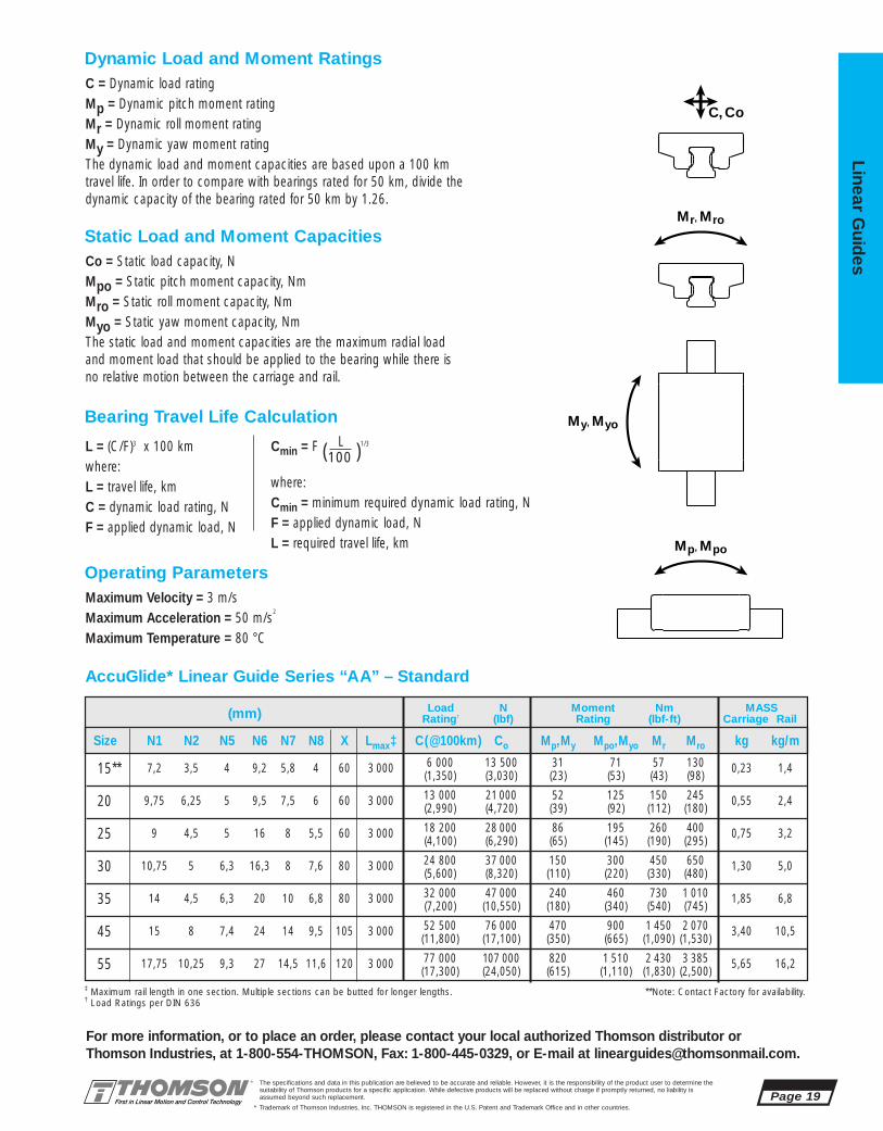
C = Dynamic load ratingMp = Dynamic pitch moment ratingMr = Dynamic roll moment ratingMy = Dynamic yaw moment ratingThe dynamic load and moment ratings are based upon a 100 km travellife. In order to compare with bearings rated for 50 km, divide thedynamic capacity of the bearing rated for 50 km by 1.26.
Dynamic Load and Moment Ratings
Co = Static load capacity, NMpo = Static pitch moment capacity, NmMro = Static roll moment capacity, NmMyo = Static yaw moment capacity, NmThe static load and moment capacities are the maximum radial load and moment load that should be applied to the bearing while there is norelative motion between the carriage and rail.
Static Load and Moment Capacities
L = (C/F)10/3 x 100 kmwhere:L = travel life, kmC = dynamic load rating, NF = applied dynamic load, N
Cmin = F( L )1/3
100
where:Cmin = minimum required dynamic load rating, NF = applied dynamic load, NL = required travel life, km
Bearing Travel Life Calculation
Maximum Velocity = 2 m/sMaximum Acceleration = 50 m/s2
Maximum Temperature = 80 °C
Operating Parameters
‡ Maximum rail length in one section. Multiple sections can be butted for longer lengths. **Note: Contact Factory for availability.

Page 14The specifications and data in this publication are believed to be accurate and reliable. However, it is the responsibility of the product user to determine thesuitability of Thomson products for a specific application. While defective products will be replaced without charge if promptly returned, no liability is assumed beyond such replacement.
* Trademark of Thomson Industries, Inc. THOMSON is registered in the U.S. Patent and Trademark Office and in other countries.
Line
ar G
uid
es
For more information, or to place an order, please contact your local authorized Thomson distributor orThomson Industries, at 1-800-554-THOMSON, Fax: 1-800-445-0329, or E-mail at [email protected].
Size: 35, 45, 55, 65****
RM 35 S LXXXX Y=
****Contact Factory for Availability
Rail Type DescriptionRM AccuMax
Rail LengthXXXX (mm)
Accuracy ClassP = PrecisionS = Super PrecisionU = Ultra Precision
Rail Suffix (See chart below)
AccuMax*Linear Guide #1Part Number Description and Specification
CM 35 AA C SCarriage Suffix (See chart below)
† Where C=Dynamic Load Capacity
****Contact Factory for Availability
Carriage Type DescriptionCM AccuMax
Size: 35, 45, 55, 65**
Style DescriptionAA Standard
Accuracy ClassP = PrecisionS = Super PrecisionU = Ultra Precision
Preload Designation DescriptionB Approx. 0,03 C
†
C Approx. 0,08 C†
D Approx. 0,13 C†
(See Note 1 below)
AM 35 A 2 S C LXXXX S Y=Assembly
Type DescriptionAM AccuMax
Size: 35, 45, 55, 65**
Style DescriptionA Standard
Accuracy ClassP = Precision S = Super Precision
U = Ultra PrecisionPreload Designation Description
B Light PreloadC Medium PreloadD Heavy Preload
****Available in AA, CE Styled Carriage Only, Preloads A & B Only.
(See Note 1 Below)
# of Carriages
Seal ConfigurationS = Full SealsU = End Seals
Rail Length(mm)
Carriage Suffix(See chart &Note 2 below
Rail Suffix(See chart &
Note 2 below)
Note 1 - Y= Distance from end of rail to center of 1stmounting hole
Note 2 - For assembly with modified carriage or rail only, useM000 as suffix for non-modified component.
SuffixProduct Options Carriage Rail
Armoloy® PlatingBellows Attachment ClipsSelf-LubricatingDouble SealsScrapersSelf-Lubricating & ScrapersDouble Seals & ScrapersLow Drag Seals (End Seals Only)
Other Modifications(Dowel Holes, Special Lube Points,Special Lubricants, Other)
-A-C2C2
-LL-KK-ZZ
-LLZZ-KKZZ-LDS-
MXXX
-A-R3R3
------
-MXXX
Contact factory
Accuracy approx. approx. approx.Class 0,03 C
†0,08 C
†0,13 C
†
P, S, U B C D
The specifications and data in this publication are believed to be accurate and reliable. However, it is the responsibility of the product user to determine thesuitability of Thomson products for a specific application. While defective products will be replaced without charge if promptly returned, no liability is assumed beyond such replacement.
* Trademark of Thomson Industries, Inc. THOMSON is registered in the U.S. Patent and Trademark Office and in other countries.
Linear Guid
es
Page 15
For more information, or to place an order, please contact your local authorized Thomson distributor orThomson Industries, at 1-800-554-THOMSON, Fax: 1-800-445-0329, or E-mail at [email protected].
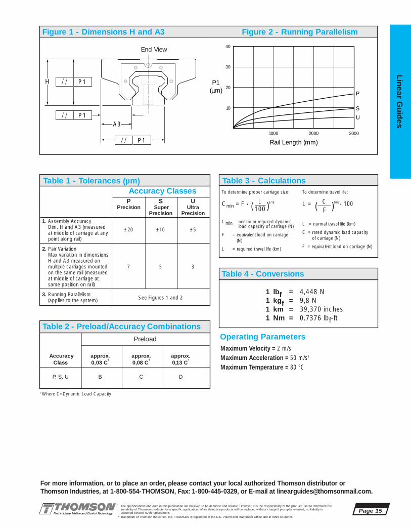
Accuracy ClassesP S U
Precision Super UltraPrecision Precision
1. Assembly AccuracyDim. H and A3 (measured at middle of carriage at any
±20 ±10 ±5
point along rail)
2. Pair VariationMax variation in dimensionsH and A3 measured on multiple carriages mounted 7 5 3on the same rail (measuredat middle of carriage atsame position on rail)
3. Running Parallelism (applies to the system) See Figures 1 and 2
1 lbf = 4,448 N1 kgf = 9,8 N1 km = 39,370 inches1 Nm = 0.7376 lbf-ft
To determine proper carriage size:
Cmin = F • ( L )3/10
100
Cmin = minimum required dynamic load capacity of carriage (N)
F = equivalent load on carriage(N)
L = required travel life (km)
To determine travel life:
L = ( C )10/3 • 100F
L = normal travel life (km)
C = rated dynamic load capacity of carriage (N)
F = equivalent load on carriage (N)
Figure 1 - Dimensions H and A3 Figure 2 - Running Parallelism
Rail Length (mm)
P1(µm) P
S
U
1000
10
20
30
40
2000 3000
A3
H
P1
P1
P1
Table 2 - Preload/Accuracy Combinations
Table 1 - Tolerances (µm)
End View
†Where C=Dynamic Load Capacity
Table 3 - Calculations
Table 4 - Conversions
Maximum Velocity = 2 m/sMaximum Acceleration = 50 m/s2
Maximum Temperature = 80 °C
Operating ParametersPreload
AccuMax Linear Roller Guide Accessories
Low Profile BellowsType B
Page 16The specifications and data in this publication are believed to be accurate and reliable. However, it is the responsibility of the product user to determine thesuitability of Thomson products for a specific application. While defective products will be replaced without charge if promptly returned, no liability is assumed beyond such replacement.
* Trademark of Thomson Industries, Inc. THOMSON is registered in the U.S. Patent and Trademark Office and in other countries.
Line
ar G
uid
es
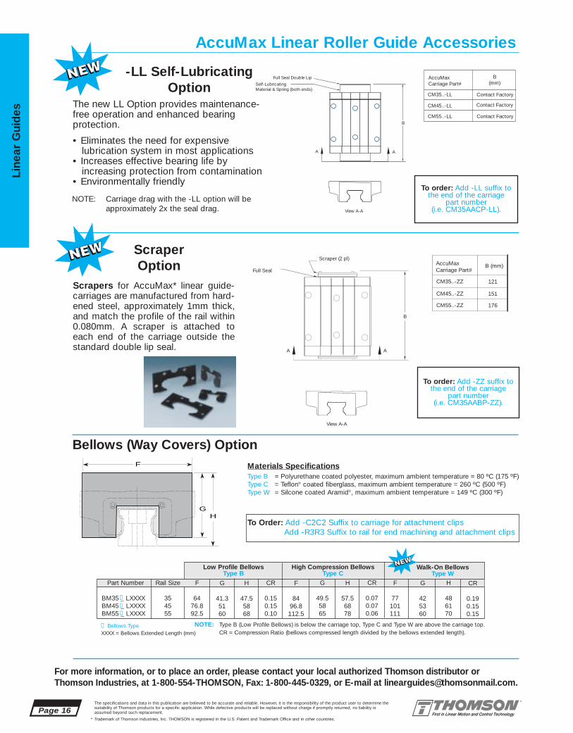
Scrapers for AccuMax* linear guide-carriages are manufactured from hard-ened steel, approximately 1mm thick,and match the profile of the rail within0.080mm. A scraper is attached toeach end of the carriage outside thestandard double lip seal.
View A-A
A A
CM55..-ZZ
CM45..-ZZ
CM35..-ZZ
AccuMaxCarriage Part#Full Seal
Scraper (2 pl)
B
121
151
176
B (mm)
To order: Add -ZZ suffix tothe end of the carriage
part number(i.e. CM35AABP-ZZ).
Scraper Option
-LL Self-Lubricating Option
Bellows (Way Covers) Option
NOTE: Type B (Low Profile Bellows) is below the carriage top, Type C and Type W are above the carriage top.
Materials SpecificationsType B = Polyurethane coated polyester, maximum ambient temperature = 80 ºC (175 ºF)Type C = Teflon® coated fiberglass, maximum ambient temperature = 260 ºC (500 ºF)Type W = Silcone coated Aramid®, maximum ambient temperature = 149 ºC (300 ºF)
The new LL Option provides maintenance-free operation and enhanced bearing protection.
• Eliminates the need for expensivelubrication system in most applications
• Increases effective bearing life byincreasing protection from contamination
• Environmentally friendly
Self-Lubricating Material & Spring (both ends)
Full Seal Double Lip
CM55..-LL
CM45..-LL
CM35..-LL
AccuMaxCarriage Part#
B(mm)
Contact Factory
View A-A
B
AA
Contact Factory
Contact Factory
To order: Add -LL suffix tothe end of the carriage
part number(i.e. CM35AACP-LL).
NOTE: Carriage drag with the -LL option will beapproximately 2x the seal drag.
GH
F
F
6476.892.5
G
41.35160
Part Number
BM35 _ LXXXXBM45 _ LXXXXBM55 _ LXXXX
Rail Size
354555
H
47.55868
CR
0.150.150.10
F
8496.8112.5
H
57.56878
CR
0.070.070.06
High Compression BellowsType C
F
77101111
G
425360
H
486170
CR
0.190.150.15
Walk-On BellowsType W
G
49.55865
CR = Compression Ratio (bellows compressed length divided by the bellows extended length).
❶
❶
❶
❶ Bellows Type
To Order: Add -C2C2 Suffix to carriage for attachment clipsAdd -R3R3 Suffix to rail for end machining and attachment clips
XXXX = Bellows Extended Length (mm)
For more information, or to place an order, please contact your local authorized Thomson distributor orThomson Industries, at 1-800-554-THOMSON, Fax: 1-800-445-0329, or E-mail at [email protected].

The specifications and data in this publication are believed to be accurate and reliable. However, it is the responsibility of the product user to determine thesuitability of Thomson products for a specific application. While defective products will be replaced without charge if promptly returned, no liability is assumed beyond such replacement.
* Trademark of Thomson Industries, Inc. THOMSON is registered in the U.S. Patent and Trademark Office and in other countries.
Linear Guid
es
Page 17
For more information, or to place an order, please contact your local authorized Thomson distributor orThomson Industries, at 1-800-554-THOMSON, Fax: 1-800-445-0329, or E-mail at [email protected].
3
2
14
NEW
5NEW
6
79 11
12
13
1415
16
8NEW 10
NEW
17NEW
■ Interchangeability in all accuracy classes and preloads, eliminating the need to prematch carriages and rails ––ordering is simplified anddowntime is minimized
■ Four easily accessible lubrication points
■ A continuous full length wiper mounted on the carriage to exclude contaminants and retain lubrication
■ A reduced lead time for all accuracy classesand preloads
■ Product availability from over 1800 authorized distributor locations, worldwide
■ An industry-standard envelope for interchange-ability with existing ball guide systems. This provides a U.S. manufactured source, with off-the-shelf availability
Thomson AccuGlide* Linear Ball Guides Offer:
AccuGlide Linear Ball Guides #2
INDUSTRY STANDARD ENVELOPE,INTERCHANGEABLE COMPONENTS
FOR ACTUATED SYSTEMS CONTAINING THIS TYPE OF LINEAR GUIDE, SEE PAGES 260, 274, and 284
Page 18The specifications and data in this publication are believed to be accurate and reliable. However, it is the responsibility of the product user to determine thesuitability of Thomson products for a specific application. While defective products will be replaced without charge if promptly returned, no liability is assumed beyond such replacement.
* Trademark of Thomson Industries, Inc. THOMSON is registered in the U.S. Patent and Trademark Office and in other countries.
Line
ar G
uid
es
For more information, or to place an order, please contact your local authorized Thomson distributor orThomson Industries, at 1-800-554-THOMSON, Fax: 1-800-445-0329, or E-mail at [email protected].
(mm)
E3
E1
S5
N8
E2 B
XY†
L
S6
A2A1
A
A3
N7
N5N2
N1
N6H2
S2 Thread
S1 Screw Size
H1H
S3 Screw Size
**Note: Contact Factory for availability.
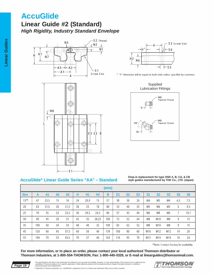
AccuGlideLinear Guide #2 (Standard)High Rigidity, Industry Standard Envelope
Size A A1 A2 A3 H H1 H2 B E1 E2 E3 S1 S2 S3 S5 S6
15** 47 23,5 15 16 24 20,9 15 57 38 30 26 M4 M5 M4 4,5 7,5
20 63 31,5 20 21,5 30 25 18 80 53 40 35 M5 M6 M5 6 9,5
25 70 35 23 23,5 36 29,5 24,5 86 57 45 40 M6 M8 M6 7 10,7
30 90 45 28 31 42 35 28,25 100 72 52 44 M8 M10 M8 9 15
35 100 50 34 33 48 40 32 109 82 62 52 M8 M10 M8 9 15
45 120 60 45 37,5 60 50 40 139 100 80 60 M10 M12 M12 14 20
55 140 70 53 43,5 70 57 46 163 116 95 70 M12 M14 M14 16 24
AccuGlide* Linear Guide Series “AA” – Standard
SuppliedLubrication Fittings
M6 Tapered Thread
M6 Tapered Thread
9
15
45°
Drop-in replacement for type HSR A, B, CA, & CBstyle guides manufactured by THK Co., LTD. (Japan)
† “Y” dimension will be equal on both ends unless specified by customer.
The specifications and data in this publication are believed to be accurate and reliable. However, it is the responsibility of the product user to determine thesuitability of Thomson products for a specific application. While defective products will be replaced without charge if promptly returned, no liability is assumed beyond such replacement.
* Trademark of Thomson Industries, Inc. THOMSON is registered in the U.S. Patent and Trademark Office and in other countries.
Linear Guid
es
Page 19
For more information, or to place an order, please contact your local authorized Thomson distributor orThomson Industries, at 1-800-554-THOMSON, Fax: 1-800-445-0329, or E-mail at [email protected].
Size N1 N2 N5 N6 N7 N8 X Lmax‡ C(@100km) Co Mp,My Mpo,Myo Mr Mro kg kg/m
15** 7,2 3,5 4 9,2 5,8 4 60 3 000 6 000 13 500 31 71 57 130 0,23 1,4(1,350) (3,030) (23) (53) (43) (98)
20 9,75 6,25 5 9,5 7,5 6 60 3 000 13 000 21 000 52 125 150 245 0,55 2,4(2,990) (4,720) (39) (92) (112) (180)
25 9 4,5 5 16 8 5,5 60 3 000 18 200 28 000 86 195 260 400 0,75 3,2(4,100) (6,290) (65) (145) (190) (295)
30 10,75 5 6,3 16,3 8 7,6 80 3 000 24 800 37 000 150 300 450 650 1,30 5,0(5,600) (8,320) (110) (220) (330) (480)
35 14 4,5 6,3 20 10 6,8 80 3 000 32 000 47 000 240 460 730 1 010 1,85 6,8(7,200) (10,550) (180) (340) (540) (745)
45 15 8 7,4 24 14 9,5 105 3 000 52 500 76 000 470 900 1 450 2 070 3,40 10,5(11,800) (17,100) (350) (665) (1,090) (1,530)
55 17,75 10,25 9,3 27 14,5 11,6 120 3 000 77 000 107 000 820 1 510 2 430 3 385 5,65 16,2(17,300) (24,050) (615) (1,110) (1,830) (2,500)
Mr, Mro
Mp, Mpo
My, Myo
C, Co
AccuGlide* Linear Guide Series “AA” – Standard
C = Dynamic load ratingMp = Dynamic pitch moment ratingMr = Dynamic roll moment ratingMy = Dynamic yaw moment ratingThe dynamic load and moment capacities are based upon a 100 kmtravel life. In order to compare with bearings rated for 50 km, divide thedynamic capacity of the bearing rated for 50 km by 1.26.
Dynamic Load and Moment Ratings
Co = Static load capacity, NMpo = Static pitch moment capacity, NmMro = Static roll moment capacity, NmMyo = Static yaw moment capacity, NmThe static load and moment capacities are the maximum radial loadand moment load that should be applied to the bearing while there isno relative motion between the carriage and rail.
Static Load and Moment Capacities
L = (C/F)3 x 100 kmwhere:L = travel life, kmC = dynamic load rating, NF = applied dynamic load, N
Bearing Travel Life Calculation
Maximum Velocity = 3 m/sMaximum Acceleration = 50 m/s
2
Maximum Temperature = 80 °C
Operating Parameters
‡ Maximum rail length in one section. Multiple sections can be butted for longer lengths. **Note: Contact Factory for availability.† Load Ratings per DIN 636
Load N Rating† (lbf)
MASSCarriage Rail
Moment Nm Rating (lbf-ft)(mm)
Cmin = F ( L )1/3
100
where:Cmin = minimum required dynamic load rating, NF = applied dynamic load, NL = required travel life, km

Page 20The specifications and data in this publication are believed to be accurate and reliable. However, it is the responsibility of the product user to determine thesuitability of Thomson products for a specific application. While defective products will be replaced without charge if promptly returned, no liability is assumed beyond such replacement.
* Trademark of Thomson Industries, Inc. THOMSON is registered in the U.S. Patent and Trademark Office and in other countries.
Line
ar G
uid
es
For more information, or to place an order, please contact your local authorized Thomson distributor orThomson Industries, at 1-800-554-THOMSON, Fax: 1-800-445-0329, or E-mail at [email protected].
(mm)
SuppliedLubrication Fittings
M6 Tapered Thread
M6 Tapered Thread
9
15
45°
E1
S5
XY†
L
E3
N8
E2 B
S6
A2A1
A
A3
N7
N2
N1
N6H2
S2 Thread
S1 Screw Size
H1H
S3 Screw SizeN5
† “Y” dimension will be equal on both ends unless specified by customer.
AccuGlideLinear Guide #2 (Standard Long)High Rigidity, Industry Standard Envelope
AccuGlide* Linear Guide Series “BA” – Standard Long
Size A A1 A2 A3 H H1 H2 B E1 E2 E3 S1 S2 S3 S5 S6
20 63 31,5 20 21,5 30 25 18 102 53 40 35 M5 M6 M5 6 9,5
25 70 35 23 23,5 36 29,5 24,5 105 57 45 40 M6 M8 M6 7 10,7
30 90 45 28 31 42 35 28,25 122 72 52 44 M8 M10 M8 9 15
35 100 50 34 33 48 40 32 134 82 62 52 M8 M10 M8 9 15
45 120 60 45 37,5 60 50 40 171 100 80 60 M10 M12 M12 14 20
55 140 70 53 43,5 70 57 46 201 116 95 70 M12 M14 M14 16 24
Drop-in replacement for type HSR LA, LB, HA, & HBstyle guides manufactured by THK Co., LTD. (Japan)

The specifications and data in this publication are believed to be accurate and reliable. However, it is the responsibility of the product user to determine thesuitability of Thomson products for a specific application. While defective products will be replaced without charge if promptly returned, no liability is assumed beyond such replacement.
* Trademark of Thomson Industries, Inc. THOMSON is registered in the U.S. Patent and Trademark Office and in other countries.
Linear Guid
es
Page 21
For more information, or to place an order, please contact your local authorized Thomson distributor orThomson Industries, at 1-800-554-THOMSON, Fax: 1-800-445-0329, or E-mail at [email protected].
Load N Rating† (lbf)
Moment Nm Rating (lbf-ft)(mm) MASS
Carriage Rail
Size N1 N2 N5 N6 N7 N8 X Lmax‡ C(@100km) Co Mp,My Mpo,Myo Mr Mro kg kg/m
20 9,75 6,25 5 9,5 7,5 6 60 3 000 17 400 30 000 64 160 210 350 0,71 2,4(3,900) (6,740) (48) (120) (160) (260)
25 9 4,5 5 16 8 5,5 60 3 000 22 700 39 000 102 255 320 550 1,00 3,2(5,100) (8,770) (77) (190) (240) (405)
30 10,75 5 6,3 16,3 8 7,6 80 3 000 31 000 50 000 170 390 550 900 1,60 5,0(7,000) (11,250) (130) (290) (410) (665)
35 14 4,5 6,3 20 10 6,8 80 3 000 40 200 66 000 270 600 870 1 410 2,45 6,8(9,050) (14,850) (205) (445) (650) (1,040)
45 15 8 7,4 24 14 9,5 105 3 000 66 000 106 000 550 1 180 1 780 2 850 4,50 10,5(14,800) (23,850) (410) (870) (1,330) (2,100)
55 17,75 10,25 9,3 27 14,5 11,6 120 3 000 97 000 148 000 965 1 970 3 050 4 670 7,50 16,2(21,800) (33,250) (710) (1,450) (2,250) (3,440)
Mr, Mro
Mp, Mpo
My, Myo
C, CoC = Dynamic load ratingMp = Dynamic pitch moment ratingMr = Dynamic roll moment ratingMy = Dynamic yaw moment ratingThe dynamic load and moment ratings are based upon a 100 km travellife. In order to compare with bearings rated for 50 km, divide thedynamic capacity of the bearing rated for 50 km by 1.26.
Dynamic Load and Moment Ratings
Co = Static load capacityMpo = Static pitch moment capacityMro = Static roll moment capacityMyo = Static yaw moment capacityThe static load and moment capacities are the maximum radial load and moment load that should be applied to the bearing while there is norelative motion between the carriage and rail.
Static Load and Moment Capacities
L = (C/F)3 x 100 kmwhere:L = travel life, kmC = dynamic load rating, NF = applied dynamic load, N
Bearing Travel Life Calculation
Maximum Velocity = 3 m/sMaximum Acceleration = 50 m/s
2
Maximum Temperature = 80 °C
Operating Parameters
‡ Maximum rail length in one section. Multiple sections can be butted for longer lengths.† Load Ratings per DIN 636
AccuGlide* Linear Guide Series “BA” – Standard Long
Cmin = F ( L )1/3
100
where:Cmin = minimum required dynamic load rating, NF = applied dynamic load, NL = required travel life, km
(mm)
Page 22The specifications and data in this publication are believed to be accurate and reliable. However, it is the responsibility of the product user to determine thesuitability of Thomson products for a specific application. While defective products will be replaced without charge if promptly returned, no liability is assumed beyond such replacement.
* Trademark of Thomson Industries, Inc. THOMSON is registered in the U.S. Patent and Trademark Office and in other countries.
Line
ar G
uid
es
For more information, or to place an order, please contact your local authorized Thomson distributor orThomson Industries, at 1-800-554-THOMSON, Fax: 1-800-445-0329, or E-mail at [email protected].
SuppliedLubrication Fittings
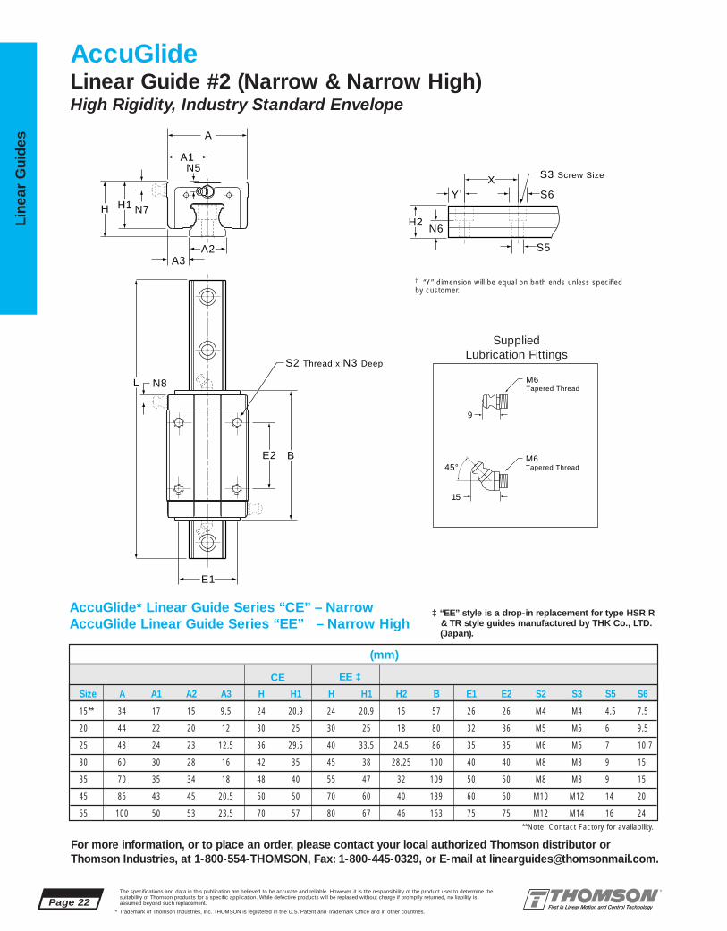
AccuGlideLinear Guide #2 (Narrow & Narrow High)High Rigidity, Industry Standard Envelope
E1
L
E2 B
S2 Thread x N3 Deep
N8
S5
XY†
N6H2
S6
S3 Screw Size
A2
A1
A
A3
H1H N7
N5
M6 Tapered Thread
M6 Tapered Thread
9
15
45°
**Note: Contact Factory for availability.
AccuGlide* Linear Guide Series “CE” – NarrowAccuGlide Linear Guide Series “EE” – Narrow High
Size A A1 A2 A3 H H1 H H1 H2 B E1 E2 S2 S3 S5 S6
15** 34 17 15 9,5 24 20,9 24 20,9 15 57 26 26 M4 M4 4,5 7,5
20 44 22 20 12 30 25 30 25 18 80 32 36 M5 M5 6 9,5
25 48 24 23 12,5 36 29,5 40 33,5 24,5 86 35 35 M6 M6 7 10,7
30 60 30 28 16 42 35 45 38 28,25 100 40 40 M8 M8 9 15
35 70 35 34 18 48 40 55 47 32 109 50 50 M8 M8 9 15
45 86 43 45 20.5 60 50 70 60 40 139 60 60 M10 M12 14 20
55 100 50 53 23,5 70 57 80 67 46 163 75 75 M12 M14 16 24
‡ “EE” style is a drop-in replacement for type HSR R& TR style guides manufactured by THK Co., LTD.(Japan).
† “Y” dimension will be equal on both ends unless specified by customer.
CE EE ‡

The specifications and data in this publication are believed to be accurate and reliable. However, it is the responsibility of the product user to determine thesuitability of Thomson products for a specific application. While defective products will be replaced without charge if promptly returned, no liability is assumed beyond such replacement.
* Trademark of Thomson Industries, Inc. THOMSON is registered in the U.S. Patent and Trademark Office and in other countries.
Linear Guid
es
Page 23
For more information, or to place an order, please contact your local authorized Thomson distributor orThomson Industries, at 1-800-554-THOMSON, Fax: 1-800-445-0329, or E-mail at [email protected].
AccuGlide* Linear Guide Series “CE” – NarrowAccuGlide Linear Guide Series “EE” - Narrow High
MASSCarriage Rail
Moment Nm Rating (lbf-ft)
Load N Rating† (lbf)(mm)
Mr, Mro
Mp, Mpo
My, Myo
C, Co
‡ Maximum rail length in one section. Multiple sections can be butted for longer lengths. **Note: Contact Factory for availability.† Load Ratings per DIN 636
Size N3 N5 N6 N7 N8 X Lmax‡ C(@100km) Co Mp,My Mpo,Myo Mr Mro kg kg/m
15** 4 4 9,2 n/a n/a 60 3 000 6 000 13 500 31 71 57 130 0,20 1,4(1,350) (3,030) (23) (53) (43) (98)
20 6 5 9,5 n/a n/a 60 3 000 13 000 21 000 52 125 150 245 0,40 2,4(2,990) (4,720) (39) (92) (112) (180)
25 9 5 16 5,3 5,5 60 3 000 18 200 28 000 86 195 260 400 0,55 3,2(4,100) (6,290) (65) (145) (190) (295)
30 12 6,3 16,3 6,3 7,6 80 3 000 24 800 37 000 150 300 450 650 0,90 5,0(5,600) (8,320) (110) (220) (330) (480)
35 13 6,3 20 6,3 8,2 80 3 000 32 000 47 000 240 460 730 1 010 1,20 6,8(7,200) (10,550) (180) (340) (540) (745)
45 18 7,3 24 7,3 9 105 3 000 52 500 76 000 470 900 1 450 2 070 2,30 10,5(11,800) (17,100) (350) (665) (1,090) (1,530)
55 18,7 9,3 27 9,3 11,6 120 3 000 77 000 107 000 820 1 510 2 430 3 385 3,80 16,2(17,300) (24,050) (615) (1,110) (1,830) (2,500)
C = Dynamic load ratingMp = Dynamic pitch moment ratingMr = Dynamic roll moment ratingMy = Dynamic yaw moment ratingThe dynamic load and moment ratings are based upon a 100 km travellife. In order to compare with bearings rated for 50 km, divide thedynamic capacity of the bearing rated for 50 km by 1.26.
Dynamic Load and Moment Ratings
Co = Static load capacityMpo = Static pitch moment capacityMro = Static roll moment capacityMyo = Static yaw moment capacityThe static load and moment capacities are the maximum radial load and moment load that should be applied to the bearing while there is no relative motion between the carriage and rail.
Static Load and Moment Capacities
L = (C/F)3 x 100 kmwhere:L = travel life, kmC = dynamic load rating, NF = applied dynamic load, N
Bearing Travel Life Calculation
Maximum Velocity = 3 m/sMaximum Acceleration = 50 m/s
2
Maximum Temperature = 80 °C
Operating Parameters
Cmin = F ( L )1/3
100
where:Cmin = minimum required dynamic load rating, NF = applied dynamic load, NL = required travel life, km

Page 24The specifications and data in this publication are believed to be accurate and reliable. However, it is the responsibility of the product user to determine thesuitability of Thomson products for a specific application. While defective products will be replaced without charge if promptly returned, no liability is assumed beyond such replacement.
* Trademark of Thomson Industries, Inc. THOMSON is registered in the U.S. Patent and Trademark Office and in other countries.
Line
ar G
uid
es
For more information, or to place an order, please contact your local authorized Thomson distributor orThomson Industries, at 1-800-554-THOMSON, Fax: 1-800-445-0329, or E-mail at [email protected].
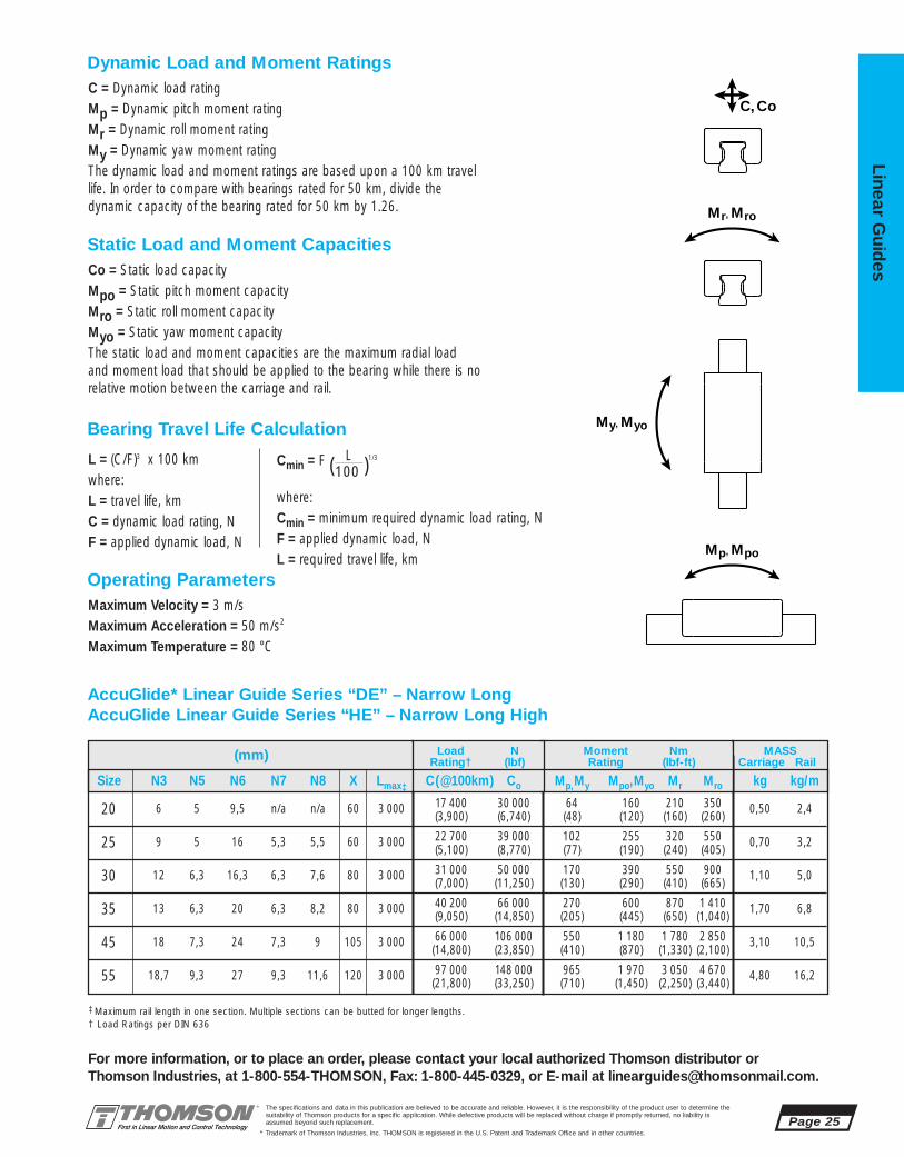
AccuGlide* Linear Guide Series “DE” – Narrow LongAccuGlide Linear Guide Series “HE” – Narrow Long High
SuppliedLubrication Fittings
S2 Thread x N3 Deep
N8
E1
E2 B
L
S5
XY†
A2
A1
A
A3
N6H2
H1HS6
N7
N5S3 Screw Size
AccuGlideLinear Guide #2 (Narrow Long)High Rigidity, Industry Standard Envelope
† “Y” dimension will be equal on both ends unless specified by customer.
M6 Tapered Thread
M6 Tapered Thread
9
15
45°
‡ “HE” style is a drop-in replacement fortype HSR LR & HTR style guides manufactured by THK Co., LTD. (Japan).
(mm)
Size A A1 A2 A3 H H1 H H1 H2 B E1 E2 S2 S3 S5 S6
20 44 22 20 12 30 25 30 25 18 102 32 50 M5 M5 6 9,5
25 48 24 23 12,5 36 29,5 36 29,5 24,5 105 32 50 M6 M6 7 10,7
30 60 30 28 16 42 35 45 38 28,25 122 40 60 M8 M8 9 15
35 70 35 34 18 48 40 55 47 32 134 50 72 M8 M8 9 15
45 86 43 45 20.5 60 50 70 60 40 171 60 80 M10 M12 14 20
55 100 50 53 23,5 70 57 80 67 46 201 75 95 M12 M14 16 24
DE HE ‡
The specifications and data in this publication are believed to be accurate and reliable. However, it is the responsibility of the product user to determine thesuitability of Thomson products for a specific application. While defective products will be replaced without charge if promptly returned, no liability is assumed beyond such replacement.
* Trademark of Thomson Industries, Inc. THOMSON is registered in the U.S. Patent and Trademark Office and in other countries.
Linear Guid
es
Page 25
For more information, or to place an order, please contact your local authorized Thomson distributor orThomson Industries, at 1-800-554-THOMSON, Fax: 1-800-445-0329, or E-mail at [email protected].
AccuGlide* Linear Guide Series “DE” – Narrow LongAccuGlide Linear Guide Series “HE” – Narrow Long High
MASSCarriage Rail
Mr, Mro
Mp, Mpo
My, Myo
C, Co
‡ Maximum rail length in one section. Multiple sections can be butted for longer lengths.† Load Ratings per DIN 636
C = Dynamic load ratingMp = Dynamic pitch moment ratingMr = Dynamic roll moment ratingMy = Dynamic yaw moment ratingThe dynamic load and moment ratings are based upon a 100 km travellife. In order to compare with bearings rated for 50 km, divide thedynamic capacity of the bearing rated for 50 km by 1.26.
Dynamic Load and Moment Ratings
Co = Static load capacityMpo = Static pitch moment capacityMro = Static roll moment capacityMyo = Static yaw moment capacityThe static load and moment capacities are the maximum radial load and moment load that should be applied to the bearing while there is norelative motion between the carriage and rail.
Static Load and Moment Capacities
L = (C/F)3 x 100 kmwhere:L = travel life, kmC = dynamic load rating, NF = applied dynamic load, N
Bearing Travel Life Calculation
Maximum Velocity = 3 m/sMaximum Acceleration = 50 m/s2
Maximum Temperature = 80 °C
Operating Parameters
Moment Nm Rating (lbf-ft)
Load N Rating† (lbf)(mm)
Cmin = F ( L )1/3
100
where:Cmin = minimum required dynamic load rating, NF = applied dynamic load, NL = required travel life, km
Size N3 N5 N6 N7 N8 X Lmax‡ C(@100km) Co Mp,My Mpo,Myo Mr Mro kg kg/m
20 6 5 9,5 n/a n/a 60 3 000 17 400 30 000 64 160 210 350 0,50 2,4(3,900) (6,740) (48) (120) (160) (260)
25 9 5 16 5,3 5,5 60 3 000 22 700 39 000 102 255 320 550 0,70 3,2(5,100) (8,770) (77) (190) (240) (405)
30 12 6,3 16,3 6,3 7,6 80 3 000 31 000 50 000 170 390 550 900 1,10 5,0(7,000) (11,250) (130) (290) (410) (665)
35 13 6,3 20 6,3 8,2 80 3 000 40 200 66 000 270 600 870 1 410 1,70 6,8(9,050) (14,850) (205) (445) (650) (1,040)
45 18 7,3 24 7,3 9 105 3 000 66 000 106 000 550 1 180 1 780 2 850 3,10 10,5(14,800) (23,850) (410) (870) (1,330) (2,100)
55 18,7 9,3 27 9,3 11,6 120 3 000 97 000 148 000 965 1 970 3 050 4 670 4,80 16,2(21,800) (33,250) (710) (1,450) (2,250) (3,440)

Page 26The specifications and data in this publication are believed to be accurate and reliable. However, it is the responsibility of the product user to determine thesuitability of Thomson products for a specific application. While defective products will be replaced without charge if promptly returned, no liability is assumed beyond such replacement.
* Trademark of Thomson Industries, Inc. THOMSON is registered in the U.S. Patent and Trademark Office and in other countries.
Line
ar G
uid
es
For more information, or to place an order, please contact your local authorized Thomson distributor orThomson Industries, at 1-800-554-THOMSON, Fax: 1-800-445-0329, or E-mail at [email protected].
AccuGlide*Linear Guide #2Part Number Description and Specification
CG 25 AA A NCarriage Suffix(See Chart Below)
Carriage Type DescriptionCG AccuGlide
Size: 15**, 20, 25, 30, 35, 45, 55Style DescriptionAA StandardBA Standard LongCE NarrowDE Narrow LongEE Narrow HighHE Narrow High Long
Accuracy ClassN = Normal P = PrecisionH = High S = Super
U = Ultra Precision
Preload Designation DescriptionA ClearanceB Approx. 0,03 C
†
C Approx. 0,08 C†
D Approx. 0,13 C†
RG 25 N LXXXX Y=
† Where C=Dynamic Load Capacity****Available in AA & CE Styled Carriage Only and Preloads A & B Only.
Rail Type DescriptionRG AccuGlide
Rail LengthXXXX (mm)
Accuracy ClassN = Normal P = PrecisionH = High S = Super
U = Ultra Precision
Rail Suffix (See Chart Below)
AG 25 A 2 S B LXXXX N Y=Assembly
Type DescriptionAG AccuGlide Assembly
Size: 15**, 20, 25, 30, 35, 45, 55
Style DescriptionA StandardB Standard LongC NarrowD Narrow LongE Narrow HighH Narrow High Long
Accuracy ClassN = Normal P = PrecisionH = High S = Super Precision
U = Ultra Precision
Preload Designation DescriptionA ClearanceB Light PreloadC Medium PreloadD Heavy Preload****Available in AA & CE Styled Carriage Only and
Preloads A & B Only.
Size: 15, 20, 25, 30, 35, 45, 55
SuffixProduct Options Carriage Rail
Armoloy® PlatingBellows Attachment ClipsSelf-LubricatingDouble SealsScrapersSelf-Lubricating & ScrapersDouble Seals & ScrapersLow Drag Seals (End Seals Only)Other Modifications(Dowel Holes, Special Lube Points,Special Lubricants, Other)
-A-C2C2
-LL-KK-ZZ
-LLZZ-KKZZ-LDS
-MXXX
-A-R3R3
------
-MXXX
(See Note 1 Below)
(See Note 1 Below)
# of Carriages
Seal ConfigurationS = Full SealsU = End Seals
Rail Length(mm)
Carriage Suffix(See chart &
Note 2 below)
Rail Suffix(See chart &
Note 2 below)
Note 1 - Y= Distance from end of rail to center of 1st mounting hole
Note 2 - For assembly with modified carriage or rail only, use M000 as suffix for non-modified component.
Note 3 - For a Ball Screw Actuated System using AccuGlide* linearguides, see page 260 in the Systems section of this catalog.
Note 4 - For a Belt Actuated System using AccuGlide* linearguides, see page 274 and 284 in the Systems section of this catalog.
Contact Factory

The specifications and data in this publication are believed to be accurate and reliable. However, it is the responsibility of the product user to determine thesuitability of Thomson products for a specific application. While defective products will be replaced without charge if promptly returned, no liability is assumed beyond such replacement.
* Trademark of Thomson Industries, Inc. THOMSON is registered in the U.S. Patent and Trademark Office and in other countries.
Linear Guid
es
Page 27
For more information, or to place an order, please contact your local authorized Thomson distributor orThomson Industries, at 1-800-554-THOMSON, Fax: 1-800-445-0329, or E-mail at [email protected].
Accuracy ClassesN H P S U
Normal High Precision Super UltraPrecision Precision
1. Dim. H and A3 (measured at middle ±100 ±40 ±20 ±10 ±5of carriage at any point along rail)
2. Max variation in dimensions H and A3 measured on multiple carriages mounted 30 15 7 5 3on the same rail (measured at middle of carriage at same position on rail)
3. Parallelism (applies to the See Figures 1 and 2system)
1 lbf = 4,448 N1 kgf = 9,8 N1 km = 39,370 inches1 Nm = 0.7376 lbf-ft
To determine proper carriage size:
Cmin = F • ( 100 )1/3
L
Cmin = minimum required dynamicload capacity of carriage (N)
F = equivalent load on carriage (N)
L = required travel life (km)
To determine travel life:
L = ( C )3• 100
FL = normal travel life (km)
C = rated dynamic load capacity of carriage (N)
F = equivalent load on carriage (N)
Figure 1 - Running Parallelism Figure 2 - Running Parallelism
Table 3 - Calculations
Rail Length (mm)
P1(µm) P
H
N
S
U
1000
10
20
30
40
2000 3000
A3
H
P1
P1
P1
Table 1 - Tolerances (µm)
End View
Clearance Preload
Accuracy up to approx. approx. approx.Class 10 µm 0,03 C
†0,08 C
†0,13 C
†
P,S,U --- B C D
N,H A B C ---
†Where C=Dynamic Load Rating
Table 4 - Conversions
Table 2 - Preload/Accuracy CombinationsMaximum Velocity = 3 m/sMaximum Acceleration = 50 m/s2
Maximum Temperature = 80 °C
Operating Parameters
Page 28The specifications and data in this publication are believed to be accurate and reliable. However, it is the responsibility of the product user to determine thesuitability of Thomson products for a specific application. While defective products will be replaced without charge if promptly returned, no liability is assumed beyond such replacement.
* Trademark of Thomson Industries, Inc. THOMSON is registered in the U.S. Patent and Trademark Office and in other countries.
Line
ar G
uid
es
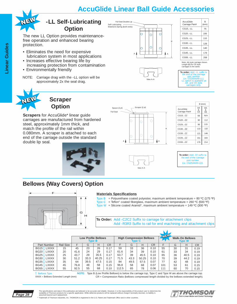
Scrapers for AccuGlide* linear guidecarriages are manufactured from hardenedsteel, approximately 1mm thick, andmatch the profile of the rail within0.080mm. A scraper is attached to eachend of the carriage outside the standarddouble lip seal.
View A-A
A A CG55..-ZZ
CG45..-ZZ
CG35..-ZZ
CG30..-ZZ
CG25..-ZZ
CG20..-ZZ
AccuGlideCarriage Part#
AA &CEFull Seal
Spacer (2 pl) Scraper (2 pl)
B
90
96
110
121
151
176
CG15..-ZZ 68
BA &DE
B (mm)
N/A
112
115
132
146
183
214
To order: Add -ZZ suffix tothe end of the carriage
part number(i.e. CG25AAAN-ZZ).
Scraper Option
-LL Self-Lubricating Option
Bellows (Way Covers) Option
NOTE: Type B (Low Profile Bellows) is below the carriage top, Type C and Type W are above the carriage top.
Materials SpecificationsType B = Polyurethane coated polyester, maximum ambient temperature = 80 ºC (175 ºF)Type C = Teflon® coated fiberglass, maximum ambient temperature = 260 ºC (500 ºF)Type W = Silcone coated Aramid®, maximum ambient temperature = 149 ºC (300 ºF)
The new LL Option provides maintenance-free operation and enhanced bearing protection.
• Eliminates the need for expensivelubrication system in most applications
• Increases effective bearing life byincreasing protection from contamination
• Environmentally friendly
Self-Lubricating Material & Spring (both ends)
Full Seal Double Lip
Note: AA style carriage shown.Length (B) for CE style carriages is the same.
CG55..-LL
CG45..-LL
CG35..-LL
CG30..-LL
CG25..-LL
CG20..-LL
AccuGlideCarriage Part#
B(mm)
106
110
128
140
178
208
CG15..-LL 75
View A-A
B
AA
To order: Add -LL suffix tothe end of the carriage
part number(i.e. CG25AAAN-LL).
-LL option is available on AA and CE style
carriages only.
NOTE: Carriage drag with the -LL option will beapproximately 2x the seal drag.
GH
F
F45
41.643.751.264
76.892.5
G232429
33.339.54855
Part NumberBG15 _ LXXXXBG20 _ LXXXXBG25 _ LXXXXBG30 _ LXXXXBG35 _ LXXXXBG45 _ LXXXXBG55 _ LXXXX
Rail Size15202530354555
H2629
35.540.2547.55868
CR0.170.170.170.170.150.150.10
Low Profile BellowsType B
F59
61.663.771.584
96.8112.5
H3639
45.550.2557.56878
CR0.100.100.100.100.070.070.06
High Compression BellowsType C
F5561657077101111
G30333639425360
H3134
40.544.2486170
CR0.190.190.190.190.190.150.15
Walk-On BellowsType W
G333439
43.349.55865
CR = Compression Ratio (bellows compressed length divided by the bellows extended length).
AccuGlide Linear Ball Guide Accessories
❶❶
❶
❶
❶
❶
❶
❶ Bellows Type
To Order: Add -C2C2 Suffix to carriage for attachment clipsAdd -R3R3 Suffix to rail for end machining and attachment clips
XXXX = Bellows Extended Length (mm)

The specifications and data in this publication are believed to be accurate and reliable. However, it is the responsibility of the product user to determine thesuitability of Thomson products for a specific application. While defective products will be replaced without charge if promptly returned, no liability is assumed beyond such replacement.
* Trademark of Thomson Industries, Inc. THOMSON is registered in the U.S. Patent and Trademark Office and in other countries.
Linear Guid
es
Page 29
3
2
1 4NEW
5NEW
67
9 1112
13
14
15
16
8NEW 10
NEW 17NEW
For more information, or to place an order, please contact your local authorized Thomson distributor orThomson Industries, at 1-800-554-THOMSON, Fax: 1-800-445-0329, or E-mail at [email protected].
AccuGlide Miniature Linear Ball Guides #3
Thomson AccuGlide* Miniature Linear Ball Guides offer:■ A superior, patented ball control design for
smooth, quiet, low friction linear motion even at high speeds
■ A patented full length integral wiper which protects important bearing components from contaminants…effective system life is maximized
■ A Gothic Arch design, which provides high rollmoment capacity...an important requirement for stand-alone applications
■ A wear-resistant, engineered polymer retainerwhich reduces system inertia and noise
■ An American manufacturing source withoff-the-shelf availability for all accuracy classesand preload levels
■ Worldwide availability from over 1800 authorized distributor locations
ULTRA COMPACT,HIGH ROLL MOMENT CAPACITY
(mm)
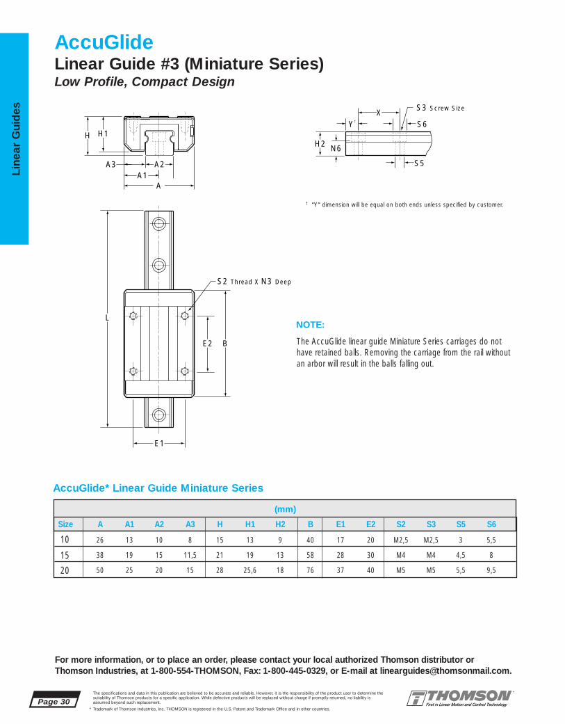
Size A A1 A2 A3 H H1 H2 B E1 E2 S2 S3 S5 S6
10 26 13 10 8 15 13 9 40 17 20 M2,5 M2,5 3 5,5
15 38 19 15 11,5 21 19 13 58 28 30 M4 M4 4,5 8
20 50 25 20 15 28 25,6 18 76 37 40 M5 M5 5,5 9,5
Page 30The specifications and data in this publication are believed to be accurate and reliable. However, it is the responsibility of the product user to determine thesuitability of Thomson products for a specific application. While defective products will be replaced without charge if promptly returned, no liability is assumed beyond such replacement.
* Trademark of Thomson Industries, Inc. THOMSON is registered in the U.S. Patent and Trademark Office and in other countries.
Line
ar G
uid
es
For more information, or to place an order, please contact your local authorized Thomson distributor orThomson Industries, at 1-800-554-THOMSON, Fax: 1-800-445-0329, or E-mail at [email protected].
A1A
A3
S2 Thread X N3 Deep
H1H
S5
XY†
N6H2
S6
E1
E2 B
L
A2
S3 Screw Size
AccuGlide Linear Guide #3 (Miniature Series)Low Profile, Compact Design
AccuGlide* Linear Guide Miniature Series
The AccuGlide linear guide Miniature Series carriages do nothave retained balls. Removing the carriage from the rail withoutan arbor will result in the balls falling out.
NOTE:
† “Y” dimension will be equal on both ends unless specified by customer.

Cmin = F ( L )1/3
100
where:Cmin = minimum required dynamic load rating, NF = applied dynamic load, NL = required travel life, km
The specifications and data in this publication are believed to be accurate and reliable. However, it is the responsibility of the product user to determine thesuitability of Thomson products for a specific application. While defective products will be replaced without charge if promptly returned, no liability is assumed beyond such replacement.
* Trademark of Thomson Industries, Inc. THOMSON is registered in the U.S. Patent and Trademark Office and in other countries.
Linear Guid
es
Page 31
For more information, or to place an order, please contact your local authorized Thomson distributor orThomson Industries, at 1-800-554-THOMSON, Fax: 1-800-445-0329, or E-mail at [email protected].
(mm) MASSCarriage Rail
Moment Nm Rating (lbf-ft)
Load N Rating (lbf)
Mr, Mro
Mp, Mpo
My, Myo
C, Co
AccuGlide* Linear Guide Miniature Series
Size N3 N6 X Lmax‡ C(@100km) Co Mp,My Mpo,Myo Mr Mro kg kg/m
10 4,5 5,5 25 1 500 2 820 5 300 10 20 15 28 0,045 0,65(635) 1,190 (7) (15) (11) (21)
15 6 7,5 40 1 500 6 375 15 200 35 66 51 96 0,141 1,42(1,430) (3,420) (26) (49) (38) (71)
20 8 9,5 60 3 000 11 870 23 000 75 140 125 235 0,345 2,55(2,670) (5,170) (55) (105) (92) (175)
‡ Maximum rail length in one section. Multiple sections can be butted for longer lengths.
C = Dynamic load ratingMp = Dynamic pitch moment ratingMr = Dynamic roll moment ratingMy = Dynamic yaw moment ratingThe dynamic load and moment ratings are based upon a 100 km travellife. In order to compare with bearings rated for 50 km, divide thedynamic capacity of the bearing rated for 50 km by 1.26.
Dynamic Load and Moment Ratings
Co = Static load capacityMpo = Static pitch moment capacityMro = Static roll moment capacityMyo = Static yaw moment capacityThe static load and moment capacities are the maximum radial load and moment load that should be applied to the bearing while there is norelative motion between the carriage and rail.
Static Load and Moment Capacities
L = (C/F)3 x 100 kmwhere:L = travel life, kmC = dynamic load rating, NF = applied dynamic load, N
Bearing Travel Life Calculation
Maximum Velocity = 3 m/sMaximum Acceleration = 50 m/s2
Maximum Temperature = 80 °C
Operating Parameters
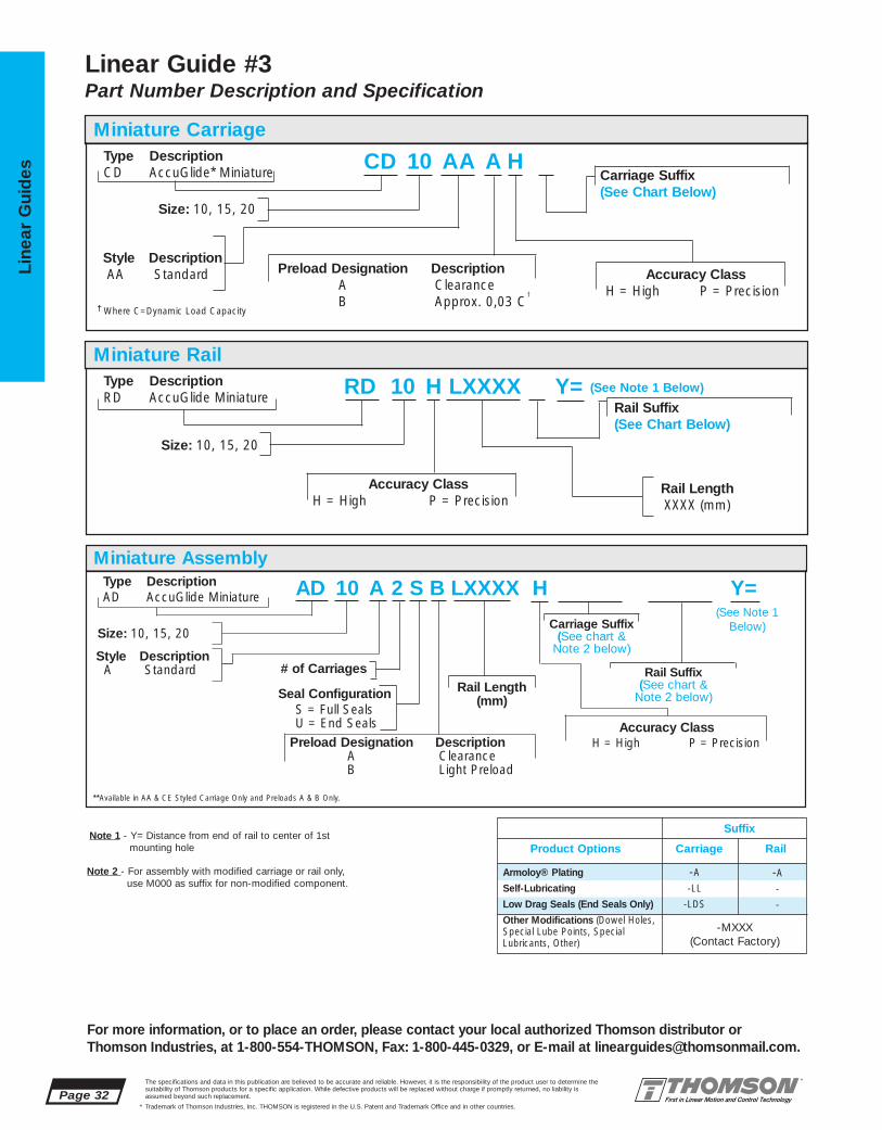
Armoloy® Plating
Self-Lubricating
Low Drag Seals (End Seals Only)
Other Modifications (Dowel Holes, Special Lube Points, Special Lubricants, Other)
Page 32The specifications and data in this publication are believed to be accurate and reliable. However, it is the responsibility of the product user to determine thesuitability of Thomson products for a specific application. While defective products will be replaced without charge if promptly returned, no liability is assumed beyond such replacement.
* Trademark of Thomson Industries, Inc. THOMSON is registered in the U.S. Patent and Trademark Office and in other countries.
Line
ar G
uid
es
For more information, or to place an order, please contact your local authorized Thomson distributor orThomson Industries, at 1-800-554-THOMSON, Fax: 1-800-445-0329, or E-mail at [email protected].
RD 10 H LXXXX Y=Miniature Rail
Type DescriptionRD AccuGlide Miniature
Size: 10, 15, 20
Rail LengthXXXX (mm)
Accuracy ClassH = High P = Precision
Rail Suffix (See Chart Below)
Linear Guide #3Part Number Description and Specification
CD 10 AA A HCarriage Suffix(See Chart Below)
† Where C=Dynamic Load Capacity
Miniature Carriage Type DescriptionCD AccuGlide* Miniature
Size: 10, 15, 20
Style DescriptionAA Standard Accuracy Class
H = High P = Precision
Preload Designation DescriptionA ClearanceB Approx. 0,03 C
†
(See Note 1 Below)
AD 10 A 2 S B LXXXX H Y=Miniature Assembly
Type DescriptionAD AccuGlide Miniature
Size: 10, 15, 20
Style DescriptionA Standard
Accuracy ClassH = High P = PrecisionPreload Designation Description
A ClearanceB Light Preload
****Available in AA & CE Styled Carriage Only and Preloads A & B Only.
Suffix
Product Options Carriage Rail
-A
-LL
-LDS
-A
-
-
(See Note 1 Below)
# of Carriages
Seal ConfigurationS = Full SealsU = End Seals
Rail Length(mm)
Carriage Suffix(See chart &
Note 2 below)
Rail Suffix(See chart &
Note 2 below)
Note 1 - Y= Distance from end of rail to center of 1stmounting hole
Note 2 - For assembly with modified carriage or rail only, use M000 as suffix for non-modified component.
-MXXX(Contact Factory)

For more information, or to place an order, please contact your local authorized Thomson distributor orThomson Industries, at 1-800-554-THOMSON, Fax: 1-800-445-0329, or E-mail at [email protected].
Page 33The specifications and data in this publication are believed to be accurate and reliable. However, it is the responsibility of the product user to determine thesuitability of Thomson products for a specific application. While defective products will be replaced without charge if promptly returned, no liability is assumed beyond such replacement.
* Trademark of Thomson Industries, Inc. THOMSON is registered in the U.S. Patent and Trademark Office and in other countries.
Linear Guid
es Sectio
n
Rail Length (mm)
P1(µm) P
H
1000
10
20
30
40
2000 3000
Clearance LightAccuracy up to approximately
Class 10 µm 0,03 C†
P ___ B
H A B
1 lbf = 4,448 N1 kgf = 9,8 N1 km = 39,370 inches1 Nm = 0.7376 lbf - ft
Accuracy ClassesH P
High Precision
1. Dim. H and A3 (measured at middle of carriage at any ±40 ±20point along rail)
2. Max variation in dimensionsH and A3 measured on multiple carriages mounted 15 7on the same rail (measuredat middle of carriage atsame position on rail)
3.Parallelism (applies to the system) See Figures 1 and 2
Figure 1 - Dimensions H and A3 Figure 2 - Running Parallelism
Table 4 - Conversions
A3
H
P1
P1
P1
Table 2 - Preload/Accuracy Combinations
Table 1 - Tolerances (µm)
End View
†Where C=Dynamic Load Rating
To determine proper carriage size:
Cmin = F • ( L )1/3
100
Cmin = minimum required dynamic load capacity of carriage (N)
F = equivalent load on carriage(N)
L = required travel life (km)
To determine travel life:
L = ( C )3 • 100F
L = normal travel life (km)
C = rated dynamic load capacity of carriage (N)
F = equivalent load on carriage (N)
Table 3 - Calculations
Maximum Velocity = 3 m/sMaximum Acceleration = 50 m/s2
Maximum Temperature = 80 °C
Operating ParametersPreload

Page 34The specifications and data in this publication are believed to be accurate and reliable. However, it is the responsibility of the product user to determine thesuitability of Thomson products for a specific application. While defective products will be replaced without charge if promptly returned, no liability is assumed beyond such replacement.
* Trademark of Thomson Industries, Inc. THOMSON is registered in the U.S. Patent and Trademark Office and in other countries.
Line
ar G
uid
es
A P P L I C A T I O N W O R K S H E E TP R O J E C T T I T L E :
N O T E S
For more information, or to place an order, please contact your local authorized Thomson distributor orThomson Industries, at 1-800-554-THOMSON, Fax: 1-800-445-0329, or E-mail at [email protected].

The specifications and data in this publication are believed to be accurate and reliable. However, it is the responsibility of the product user to determine thesuitability of Thomson products for a specific application. While defective products will be replaced without charge if promptly returned, no liability is assumed beyond such replacement.
* Trademark of Thomson Industries, Inc. THOMSON is registered in the U.S. Patent and Trademark Office and in other countries.
Linear Guid
es
Page 35
3
2
14
NEW
5NEW
6
79 11
12
13
1415
16
8NEW 10
NEW17NEW
AccuGlide* T-Series* Linear Ball Guides #4
Low Cost, High Loads, Reduced Weight■ Low purchase price
■ Easy, low cost installation. T-Series is approx.5 times more forgiving of bed preparationerrors than all steel profile rail linear guides
■ High loads up to 25 000 N (5,620 lbf)
■ Longer travel life. Proprietary design decreasesinduced loads caused by installation errors
■ 60% lower inertia of traveling guides in multi-axis systems
■ N-grade radial runout accuracy of 33 µm(0.0015 in.) over a 3 m (10 ft) length
■ Drop-in replacement with industry-standardenvelope and hole pattern
■ Long life/easy maintenance with two lubricationports per carriage and full seals
■ Less downtime with quick-turnaround from aU.S. supplier
LOW COST, COMPLIANT,INDUSTRY STANDARD ENVELOPE
For more information, or to place an order, please contact your local authorized Thomson distributor orThomson Industries, at 1-800-554-THOMSON, Fax: 1-800-445-0329, or E-mail at [email protected].

15 7,7 4,3 7,4 60 5750
20 10 6,25 7,5 60 5750
25 12 8 10 60 5750
30 14 5,8 11 80 5750
35 15,26 6,6 11 80 5750
Page 36The specifications and data in this publication are believed to be accurate and reliable. However, it is the responsibility of the product user to determine thesuitability of Thomson products for a specific application. While defective products will be replaced without charge if promptly returned, no liability is assumed beyond such replacement.
* Trademark of Thomson Industries, Inc. THOMSON is registered in the U.S. Patent and Trademark Office and in other countries.
Line
ar G
uid
es
For more information, or to place an order, please contact your local authorized Thomson distributor orThomson Industries, at 1-800-554-THOMSON, Fax: 1-800-445-0329, or E-mail at [email protected].
15 47 23,5 15 16 24 19,3 15 58 38 30 M4 M5 M4 4,5 7,5
20 63 31,5 20 21,5 30 25 18 76 53 40 M5 M6 M5 5,8 9,5
25 70 35 23 23,5 36 29,5 22 88 57 45 M6 M8 M6 7 10,7
30 90 45 28 31 42 35 26 103 72 52 M8 M10 M8 9 14
35 100 50 34 33 48 40 29 117 82 62 M8 M10 M8 9 14
A2A1
A
A3
H1H
E1
E2 BL
S2 Thread
S1 Screw Size
N1
M6 Tapered Thread
M6 Tapered Thread
9
15
45°
SuppliedLubrication Fittings
S5
X
Y†
N6H2
S6
S3 Screw Size
†- Will be equal on both ends, unless otherwise specified.
Lubrication AccessBoth Ends
N5
AccuGlide T-SeriesLinear Guide #4 (“A” Style)Low Cost, Compliant Structure, Industry Standard Envelope
(mm)
AccuGlide* T-Series* Linear Guides “A” Style
Size A A1 A2 A3 H H1 H2 B E1 E2 S1 S2 S3 S5 S6
MASSCarriage Rail
5 000 (1,125) 7 050 (1,575) 0,10 0,50
9 000 (2,025) 11 000 (2,475) 0,22 0,79
13 000 (2,925) 15 000 (3,375) 0,30 1,06
20 000 (4,500) 23 000 (5,170) 0,52 1,67
25 000 (5,620) 28 000 (6,295) 0,74 2,27
(mm)
Size N1 N5 N6 X Lmax
LoadRatings N (lbf)
C (@100km) Co kg kg/m
Dimensional replacement for type HSR A, B, CA, & CB style guides manufactured by THK Co.,LTD. (Japan). Thomson AccuGlide T-Series linear guideis approximately 4x more compliant.
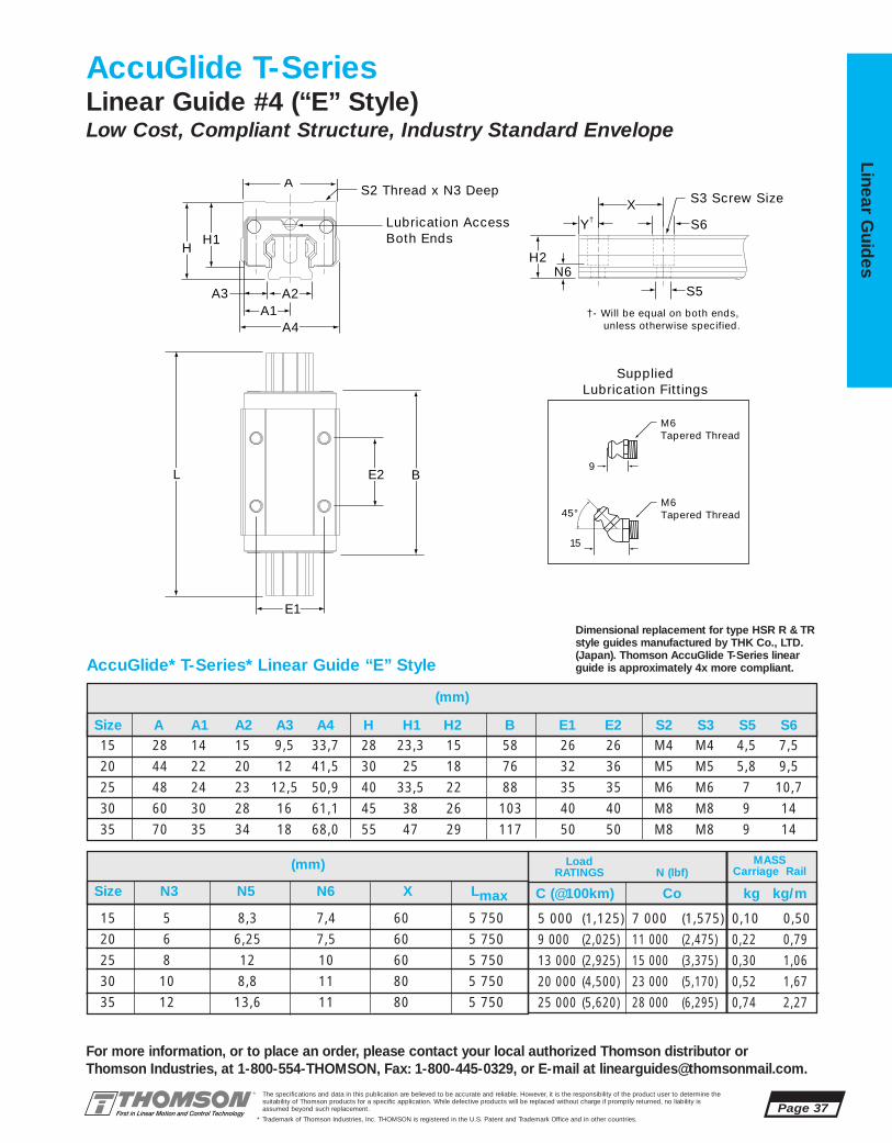
The specifications and data in this publication are believed to be accurate and reliable. However, it is the responsibility of the product user to determine thesuitability of Thomson products for a specific application. While defective products will be replaced without charge if promptly returned, no liability is assumed beyond such replacement.
* Trademark of Thomson Industries, Inc. THOMSON is registered in the U.S. Patent and Trademark Office and in other countries.
Linear Guid
es
Page 37
For more information, or to place an order, please contact your local authorized Thomson distributor orThomson Industries, at 1-800-554-THOMSON, Fax: 1-800-445-0329, or E-mail at [email protected].
15 28 14 15 9,5 33,7 28 23,3 15 58 26 26 M4 M4 4,5 7,5
20 44 22 20 12 41,5 30 25 18 76 32 36 M5 M5 5,8 9,5
25 48 24 23 12,5 50,9 40 33,5 22 88 35 35 M6 M6 7 10,7
30 60 30 28 16 61,1 45 38 26 103 40 40 M8 M8 9 14
35 70 35 34 18 68,0 55 47 29 117 50 50 M8 M8 9 14
A2A1
A4
A3
H1H
E1
E2 BL
S2 Thread x N3 DeepA
M6 Tapered Thread
M6 Tapered Thread
9
15
45°
SuppliedLubrication Fittings
Lubrication AccessBoth Ends
S5
X
Y†
N6H2
S6
S3 Screw Size
†- Will be equal on both ends, unless otherwise specified.
AccuGlide T-SeriesLinear Guide #4 (“E” Style)Low Cost, Compliant Structure, Industry Standard Envelope
(mm)
AccuGlide* T-Series* Linear Guide “E” Style
Size A A1 A2 A3 A4 H H1 H2 B E1 E2 S2 S3 S5 S6
LoadRATINGS N (lbf)
15 5 8,3 7,4 60 5 750
20 6 6,25 7,5 60 5 750
25 8 12 10 60 5 750
30 10 8,8 11 80 5 750
35 12 13,6 11 80 5 750
5 000 (1,125) 7 000 (1,575) 0,10 0,50
9 000 (2,025) 11 000 (2,475) 0,22 0,79
13 000 (2,925) 15 000 (3,375) 0,30 1,06
20 000 (4,500) 23 000 (5,170) 0,52 1,67
25 000 (5,620) 28 000 (6,295) 0,74 2,27
C (@100km) Co kg kg/m
(mm)
Size N3 N5 N6 X Lmax
MASSCarriage Rail
Dimensional replacement for type HSR R & TRstyle guides manufactured by THK Co., LTD. (Japan). Thomson AccuGlide T-Series linearguide is approximately 4x more compliant.
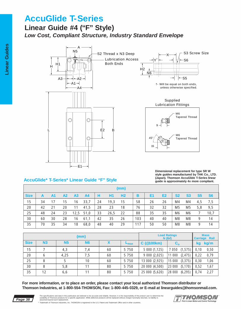
15 7 4,3 7,4 60 5 750
20 6 4,25 7,5 60 5 750
25 8 5 10 60 5 750
30 8 5,8 11 80 5 750
35 12 6,6 11 80 5 750
15 34 17 15 16 33,7 24 19,3 15 58 26 26 M4 M4 4,5 7,5
20 42 21 20 11 41,5 28 23 18 76 32 32 M5 M5 5,8 9,5
25 48 24 23 12,5 51,0 33 26,5 22 88 35 35 M6 M6 7 10,7
30 60 30 28 16 61,1 42 35 26 103 40 40 M8 M8 9 14
35 70 35 34 18 68,0 48 40 29 117 50 50 M8 M8 9 14
Page 38The specifications and data in this publication are believed to be accurate and reliable. However, it is the responsibility of the product user to determine thesuitability of Thomson products for a specific application. While defective products will be replaced without charge if promptly returned, no liability is assumed beyond such replacement.
* Trademark of Thomson Industries, Inc. THOMSON is registered in the U.S. Patent and Trademark Office and in other countries.
Line
ar G
uid
es
For more information, or to place an order, please contact your local authorized Thomson distributor orThomson Industries, at 1-800-554-THOMSON, Fax: 1-800-445-0329, or E-mail at [email protected].
(mm)
A2A1
A4
A3
H1H
E1
E2 BL
A
S2 Thread x N3 Deep
M6 Tapered Thread
M6 Tapered Thread
9
15
45°
SuppliedLubrication Fittings
Lubrication AccessBoth Ends
S5
X
Y†
N6H2
S6
S3 Screw Size
†- Will be equal on both ends, unless otherwise specified.
N5
AccuGlide T-SeriesLinear Guide #4 (“F” Style)Low Cost, Compliant Structure, Industry Standard Envelope
(mm)
AccuGlide* T-Series* Linear Guide “F” Style
Size A A1 A2 A3 A4 H H1 H2 B E1 E2 S2 S3 S5 S6
Load RatingsN (lbf)
MassCarriage Rail
Size N3 N5 N6 X Lmax
5 000 (1,125) 7 050 (1,575) 0,10 0,50
9 000 (2,025) 11 000 (2,475) 0,22 0,79
13 000 (2,925) 15 000 (3,375) 0,30 1,06
20 000 (4,500) 23 000 (5,170) 0,52 1,67
25 000 (5,620) 28 000 (6,295) 0,74 2,27
C (@100km) Co kg kg/m
Dimensional replacement for type SR W style guides manufactured by THK Co., LTD. (Japan). Thomson AccuGlide T-Series linearguide is approximately 4x more compliant.

15 7,7 4,3 7,4 60 5 750
20 8 4,25 7,5 60 5 750
25 9 5 10 60 5 750
30 14 5,8 11 80 5 750
35 15,26 6,6 11 80 5 750
15 52 26 15 16 24 19,3 15 58 41 26 M4 M5 M4 4,5 7,5
20 59 29,5 20 19,5 28 23 18 76 49 32 M5 M6 M5 5,8 9,5
25 73 36,5 23 25 33 26,5 22 88 60 35 M6 M8 M6 7 10,7
30 90 45 28 31 42 35 26 103 72 40 M8 M10 M8 9 14
35 100 50 34 33 48 40 29 117 82 50 M8 M10 M8 9 14
The specifications and data in this publication are believed to be accurate and reliable. However, it is the responsibility of the product user to determine thesuitability of Thomson products for a specific application. While defective products will be replaced without charge if promptly returned, no liability is assumed beyond such replacement.
* Trademark of Thomson Industries, Inc. THOMSON is registered in the U.S. Patent and Trademark Office and in other countries.
Linear Guid
es
Page 39
For more information, or to place an order, please contact your local authorized Thomson distributor orThomson Industries, at 1-800-554-THOMSON, Fax: 1-800-445-0329, or E-mail at [email protected].
AccuGlide* T-Series* Linear Guide “G” Style
A2A1
A
A3
H1H
E1
E2 BL
S2 Thread
S1 Screw Size
N1
M6 Tapered Thread
M6 Tapered Thread
9
15
45°
SuppliedLubrication Fittings
Lubrication AccessBoth Ends
S5
X
Y†
N6H2
S6
S3 Screw Size
†- Will be equal on both ends, unless otherwise specified.
N5
AccuGlide T-SeriesLinear Guide #4 (“G” Style)Low Cost, Compliant Structure, Industry Standard Envelope
(mm)
Size A A1 A2 A3 H H1 H2 B E1 E2 S1 S2 S3 S5 S6
(mm) Load RatingsN (lbf)
MassCarriage Rail
Size N1 N5 N6 X Lmax
5 000 (1,125) 7 050 (1,575) 0,10 0,50
9 000 (2,025) 11 000 (2,475) 0,22 0,79
13 000 (2,925) 15 000 (3,375) 0,30 1,06
20 000 (4,500) 23 000 (5,170) 0,52 1,67
25 000 (5,620) 28 000 (6,295) 0,74 2,27
C (@100km) Co kg kg/m
Dimensional Replacement for type SR TBstyle guides manufactured by THK Co., LTD. (Japan). Thomson AccuGlide T-Series linear guide is approximately 4x more compliant.

Page 40The specifications and data in this publication are believed to be accurate and reliable. However, it is the responsibility of the product user to determine thesuitability of Thomson products for a specific application. While defective products will be replaced without charge if promptly returned, no liability is assumed beyond such replacement.
* Trademark of Thomson Industries, Inc. THOMSON is registered in the U.S. Patent and Trademark Office and in other countries.
Line
ar G
uid
es
For more information, or to place an order, please contact your local authorized Thomson distributor orThomson Industries, at 1-800-554-THOMSON, Fax: 1-800-445-0329, or E-mail at [email protected].
NOTE: Carriages are dimensionally matched to rails during assembly.
Fc Ft
Fs
C = Dynamic load ratingThe dynamic load rating is basedupon a 100 km travel life. In order tocompare with bearings rated for 50km, divide the dynamic rating of thebearing rated for 50 km by 1.26.
Dynamic Load Rating
Co = Static load capacityThe static load capacity is the maximum radial load that should beapplied to the bearing while there isno relative motion between the carriage and rail.
Static Load CapacityL = (C/F)3 x 100 kmwhere:L = travel life, kmC = dynamic load rating, NF = applied dynamic load, N
Bearing Travel Life Calculation
Maximum Velocity = 3 m/sMaximum Acceleration = 50 m/s2
Maximum Temperature = 80 °C
Operating Parameters
How to determine AccuGlide T-Series Linear Guide Part Number:
1. Based on load calculations and life requirements, determine the proper AccuGlide T-Series linear guide size.
2. Select the assembly part number.
3. The “Y” dimension (distance from rail end to first mounting hole) will be equal on both ends, unless otherwise specified.
Suffix (See Chart Below)
AT 20 A 2 L XXXX Y= (See Note 3 Below)
AccuGlide* T-Series* Linear Guide Part Number Descriptions and Specifications
Rail LengthLXXXX (mm)
Rail Size: 20, 25, 30, 35
Carriage TypeA = Interchange for THK E = Interchange for THK
HSR A, B, CA, & CB HSR R & TRF = Interchange for THK SR W G = Interchange for THK SR TB
No. of CarriagesPer Rail
Type DescriptionAT AccuGlide T-Series
Part Product Options Number Suffix
Armoloy® PlatingLow Drag SealsOther Modifications(Dowel Holes, Special LubePoints, Special Lubricants,Other)
ALDS
SXXX
Fc C C
Ft C 0.6C
Fs C 0.6C
Dynamic LoadLoad Rating Limit
(Contact Factory)

The specifications and data in this publication are believed to be accurate and reliable. However, it is the responsibility of the product user to determine thesuitability of Thomson products for a specific application. While defective products will be replaced without charge if promptly returned, no liability is assumed beyond such replacement.
* Trademark of Thomson Industries, Inc. THOMSON is registered in the U.S. Patent and Trademark Office and in other countries.
Linear Guid
es
Page 41
For more information, or to place an order, please contact your local authorized Thomson distributor orThomson Industries, at 1-800-554-THOMSON, Fax: 1-800-445-0329, or E-mail at [email protected].
5NEW
3
2
14
NEW
6
79 11
12
13
1415
16
8NEW 17
NEW10NEW
FluoroNyliner* Linear Guides Offer:
FluoroNyliner Linear Guides #5
CORROSION RESISTANT, SMOOTH,QUIET, INDUSTRY STANDARD ENVELOPE
■ Thomson’s new FluoroNyliner Bushing bearingsthat are made from the most advanced polymer components to achieve maximum performance levels
■ Contamination resistance. The FluoroNylinerLinear Guides are practically immune toadverse environments, such as water wash-down conditions and magnetic interference
■ Self-Aligning Pillow Blocks for ease of use
■ Increased bearing load capacities (or ‘PV’ ratings) and obtainable travel life, when usedwith Thomson stainless steel, 60 Case* LinearRace* shaft, when compared to competitiveassemblies
■ Specification conformance with FDA and non-lubricated applications
■ Use in linear and rotary motion applications
■ Operates in temperatures from -400 ˚F(-240 ˚C) to 550 ˚F (270 ˚C).

1VA-06-AOO .375 1.31 .500 .94 1.75 FNYBUPB06A-XS1VA-08-AOO .500 1.69 .687 1.25 2.00 FNYBUPB08A-XS1VA-10-AOO .625 1.94 .875 1.63 2.50 FNYBUPB10A-XS1VA-12-AOO .750 2.06 .937 1.75 2.75 FNYBUPB12A-XS1VA-16-AOO 1.000 2.81 1.187 2.19 3.25 FNYBUPB16A-XS1VA-20-AOO 1.250 3.63 1.500 2.81 4.00 FNYBUPB20A-XS1VA-24-AOO 1.500 4.00 1.750 3.25 4.75 FNYBUPB24A-XS
1VA-06-BOO .375 2.75 .500 .94 1.75 FNYBUTWN06A-XS1VA-08-BOO .500 3.50 .687 1.25 2.00 FNYBUTWN08A-XS1VA-10-BOO .625 4.00 .875 1.63 2.50 FNYBUTWN10A-XS1VA-12-BOO .750 4.50 .937 1.75 2.75 FNYBUTWN12A-XS1VA-16-BOO 1.000 6.00 1.187 2.19 3.25 FNYBUTWN16A-XS1VA-20-BOO 1.250 7.50 1.500 2.81 4.00 FNYBUTWN20A-XS1VA-24-BOO 1.500 9.00 1.750 3.25 4.75 FNYBUTWN24A-XS
Page 42The specifications and data in this publication are believed to be accurate and reliable. However, it is the responsibility of the product user to determine thesuitability of Thomson products for a specific application. While defective products will be replaced without charge if promptly returned, no liability is assumed beyond such replacement.
* Trademark of Thomson Industries, Inc. THOMSON is registered in the U.S. Patent and Trademark Office and in other countries.
Line
ar G
uid
es
For more information, or to place an order, please contact your local authorized Thomson distributor orThomson Industries, at 1-800-554-THOMSON, Fax: 1-800-445-0329, or E-mail at [email protected].
L2
L1
B9
H8 H9
L
L
B9
H8 H9
FluoroNyliner 1VALinear Guide #5Corrosive/ContaminatedEnvironments
FluoroNyliner* Linear Guide 1VA Single Unsupported with 2 Pillow Blocks (Dimensions in inches)Part Nominal L1 H8 H9 B9 Pillow
Number Diameter Block
FluoroNyliner Linear Guide 1VA Single Unsupported with 1 Twin Pillow Block (Dimensions in inches)Part Nominal L2 H8 H9 B9 Pillow
Number Diameter Block
Single Unsupported Linear Guide with 2 Pillow Blocks
Single Unsupported Linear Guide with 1 Twin Pillow Block
INCH
Characteristic Limit
Liner Temperature Range
Velocity, dry
Velocity, dry
Velocity, lubricated
Pressure
PV
-240 ˚C to 288 ˚C (-400 ˚F to 550 ˚F)
42.7 m/min. Continuous
122 m/min. Intermittent
122 m/min. Continuous
10.35 MPa
21 MPa/m/min
Maximum Operating Parameters per BearingShaft Deflection Note:Load limit may be below the dynamic load rating due to shaftdeflection. Bearings can accommodate up to 1/2º deflection. See Engineering Section (pg 204) for deflection calculations.

FNYBUTWN06A-XS .375 2.75 2.25 .25FNYBUTWN08A-XS .500 3.50 2.50 .40FNYBUTWN10A-XS .625 4.00 3.00 1.00FNYBUTWN12A-XS .750 4.50 3.50 1.24FNYBUTWN16A-XS 1.000 6.00 4.50 2.48FNYBUTWN20A-XS 1.250 7.50 5.50 5.14FNYBUTWN24A-XS 1.500 9.00 6.50 8.08
FNYBUPB06A-XS .375 .131 .94 .500 .19 1.75 1.12 1.44 .88(2) #6 .16 .13FNYBUPB08A-XS .500 1.69 1.25 .687 .25 2.00 1.38 1.69 1.00 #6 .16 .20FNYBUPB10A-XS .625 1.94 1.63 .875 .28 2.50 1.75 2.125 1.125 #8 .19 .50FNYBUPB12A-XS .750 2.06 1.75 .937 .31 2.75 1.88 2.38 1.25 #8 .19 .62FNYBUPB16A-XS 1.000 2.81 2.19 1.187 .38 3.25 2.38 2.88 1.75 #10 .22 1.24FNYBUPB20A-XS 1.250 3.63 2.81 1.500 .43 4.00 3.00 3.50 2.00 #10 .22 2.57FNYBUPB24A-XS 1.500 4.00 3.25 1.750 .50 4.75 3.50 4.12 2.50 1⁄4 .28 3.94
The specifications and data in this publication are believed to be accurate and reliable. However, it is the responsibility of the product user to determine thesuitability of Thomson products for a specific application. While defective products will be replaced without charge if promptly returned, no liability is assumed beyond such replacement.
* Trademark of Thomson Industries, Inc. THOMSON is registered in the U.S. Patent and Trademark Office and in other countries.
Linear Guid
es
Page 43
For more information, or to place an order, please contact your local authorized Thomson distributor orThomson Industries, at 1-800-554-THOMSON, Fax: 1-800-445-0329, or E-mail at [email protected].
View A-A
Pillow BlockMounting Hole Position forSize .375
Specifying a Thomson Linear Guide:1. Determine the proper system for your load andlife requirements. 2. Select the part number. 3. Addthe letter “L” followed by the overall length in inches, as a suffix to the part number.
Part Numbering System
1VA-12-AOO L24Linear Guide Linear GuideDesignation LengthNominal Diameter
Type of Bearing Block
FluoroNyliner* Linear Guide 1VA Benefits:■ Requires only one part number to
specify entire Linear Guide.■ Design flexibility with custom end
supports.■ Used in end supported applications
when spanning or bridging a gap.
FluoroNyliner Linear Guide 1VA Components:■ 2 self-aligning FluoroNyliner
Bushing bearing pillow blocks or 1 self-aligning FluoroNyliner bushing bearing Twin Pillow block.
■ 1 Stainless Steel 60 Case*LinearRace* shaft.
Self-Aligning Pillow Blocks (Dimensions in inches)
Part Nom. L2 J3 Wt.Number Dia. lb
Housing Material: Aluminum Alloy Black Anodized(2)Two mounting holes as shown in view A-A for size .375
Performance Note: For detailed explanations of FluoroNyliner Linear GuideDynamic and Static Load Capacities, Frictional Characteristics, Wear Rates,Speeds, and Life Expectancy please contact Thomson Linear GuidesApplications Engineering department.
Product Note: FluoroNyliner linear guides are shipped free of all lubricants.It is the responsibility of the product user to determine lubricant compatibilitywith the FluoroNyliner bearing material.
Product Options: FluoroNyliner linear guides are available with various innerrace materials and platings to accommodate different environments.
Housing Material: Aluminum Alloy Black Anodized
Self-Aligning Twin Pillow Blocks
B9
A-A
H8 H5H9
B7
L1 J1 J
F
J3B9
H8 H9
L2 J
H5
B7 F
FluoroNyliner Linear Guide Pillow Block Dimensions
FluoroNyliner Linear Guide Twin Pillow Block DimensionsJ
J1
Part Nom. L1 H9 H8 H5 B9 B7 J J1 F Wt.Number Dia. Bolt Hole lb
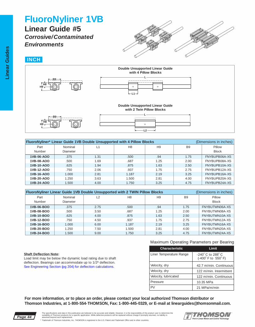
1VB-06-BOO .375 2.75 .500 .94 1.75 FNYBUTWN06A-XS1VB-08-BOO .500 3.50 .687 1.25 2.00 FNYBUTWN08A-XS1VB-10-BOO .625 4.00 .875 1.63 2.50 FNYBUTWN10A-XS1VB-12-BOO .750 4.50 .937 1.75 2.75 FNYBUTWN12A-XS1VB-16-BOO 1.000 6.00 1.187 2.19 3.25 FNYBUTWN16A-XS1VB-20-BOO 1.250 7.50 1.500 2.81 4.00 FNYBUTWN20A-XS1VB-24-BOO 1.500 9.00 1.750 3.25 4.75 FNYBUTWN24A-XS
1VB-06-AOO .375 1.31 .500 .94 1.75 FNYBUPB06A-XS1VB-08-AOO .500 1.69 .687 1.25 2.00 FNYBUPB08A-XS1VB-10-AOO .625 1.94 .875 1.63 2.50 FNYBUPB10A-XS1VB-12-AOO .750 2.06 .937 1.75 2.75 FNYBUPB12A-XS1VB-16-AOO 1.000 2.81 1.187 2.19 3.25 FNYBUPB16A-XS1VB-20-AOO 1.250 3.63 1.500 2.81 4.00 FNYBUPB20A-XS1VB-24-AOO 1.500 4.00 1.750 3.25 4.75 FNYBUPB24A-XS
Page 44The specifications and data in this publication are believed to be accurate and reliable. However, it is the responsibility of the product user to determine thesuitability of Thomson products for a specific application. While defective products will be replaced without charge if promptly returned, no liability is assumed beyond such replacement.
* Trademark of Thomson Industries, Inc. THOMSON is registered in the U.S. Patent and Trademark Office and in other countries.
Line
ar G
uid
es
For more information, or to place an order, please contact your local authorized Thomson distributor orThomson Industries, at 1-800-554-THOMSON, Fax: 1-800-445-0329, or E-mail at [email protected].
FluoroNyliner 1VBLinear Guide #5Corrosive/ContaminatedEnvironments
L2
L1
L
LB9
H8 H9
B9
H8 H9
Double Unsupported Linear Guide with 4 Pillow Blocks
Double Unsupported Linear Guidewith 2 Twin Pillow Blocks
FluoroNyliner* Linear Guide 1VB Double Unsupported with 4 Pillow Blocks (Dimensions in inches)Part Nominal L1 H8 H9 B9 Pillow
Number Diameter Block
FluoroNyliner Linear Guide 1VB Double Unsupported with 2 TWIN Pillow Blocks (Dimensions in inches)Part Nominal L2 H8 H9 B9 Pillow
Number Diameter Block
INCH
Maximum Operating Parameters per BearingCharacteristic Limit
Liner Temperature Range
Velocity, dry
Velocity, dry
Velocity, lubricated
Pressure
PV
-240˚ C to 288˚ C (-400˚ F to 550˚ F)
42.7 m/min. Continuous
122 m/min. Intermittent
122 m/min. Continuous
10.35 MPa
21 MPa/m/min
Shaft Deflection Note:Load limit may be below the dynamic load rating due to shaft deflection. Bearings can accommodate up to 1/2º deflection. See Engineering Section (pg 204) for deflection calculations.

FNYBUTWN06A-XS .375 2.75 2.25 .25FNYBUTWN08A-XS .500 3.50 2.50 .40FNYBUTWN10A-XS .625 4.00 3.00 1.00FNYBUTWN12A-XS .750 4.50 3.50 1.24FNYBUTWN16A-XS 1.000 6.00 4.50 2.48FNYBUTWN20A-XS 1.250 7.50 5.50 5.14FNYBUTWN24A-XS 1.500 9.00 6.50 8.08
FNYBUPB06A-XS .375 .131 .94 .500 .19 1.75 1.12 1.44 .88(2) #6 .16 .13FNYBUPB08A-XS .500 1.69 1.25 .687 .25 2.00 1.38 1.69 1.00 #6 .16 .20FNYBUPB10A-XS .625 1.94 1.63 .875 .28 2.50 1.75 2.125 1.125 #8 .19 .50FNYBUPB12A-XS .750 2.06 1.75 .937 .31 2.75 1.88 2.38 1.25 #8 .19 .62FNYBUPB16A-XS 1.000 2.81 2.19 1.187 .38 3.25 2.38 2.88 1.75 #10 .22 1.24FNYBUPB20A-XS 1.250 3.63 2.81 1.500 .43 4.00 3.00 3.50 2.00 #10 .22 2.57FNYBUPB24A-XS 1.500 4.00 3.25 1.750 .50 4.75 3.50 4.12 2.50 1⁄4 .28 3.94
The specifications and data in this publication are believed to be accurate and reliable. However, it is the responsibility of the product user to determine thesuitability of Thomson products for a specific application. While defective products will be replaced without charge if promptly returned, no liability is assumed beyond such replacement.
* Trademark of Thomson Industries, Inc. THOMSON is registered in the U.S. Patent and Trademark Office and in other countries.
Linear Guid
es
Page 45
For more information, or to place an order, please contact your local authorized Thomson distributor orThomson Industries, at 1-800-554-THOMSON, Fax: 1-800-445-0329, or E-mail at [email protected].
FluoroNyliner* Linear Guide 1VB Benefits:■ Allows for custom table mounting.■ Design flexibility for custom end
supports.■ Double LinearRace* shaft
configuration resists torque.■ Used in end supported applications
when spanning or bridging a gap.
FluoroNyliner Linear Guide 1VB Components:■ 4 self-aligning FluoroNyliner Bushing
bearing pillow blocks or 2 self-aligning FluoroNyliner Bushing bearing Twin Pillow blocks.
■ 2 Stainless Steel 60 Case*LinearRace shafts.
Specifying a Thomson Linear Guide:1. Determine the proper system for your load andlife requirements. 2. Select the part number.3. Add the letter “L” followed by the overall lengthin inches, as a suffix to the part number.
Part Numbering System
1VB-12-AOO L24Linear Guide Linear GuideDesignation LengthNominal Diameter
Type of Bearing Block
Pillow BlockMounting Hole Position forSize .375
View A-A
B9
A-A
H8 H5H9
B7
L1 J1 J
F
J3B9
H8 H9
L2 J
H5
B7 F
FluoroNyliner Linear Guide Pillow Block Dimensions
FluoroNyliner Linear Guide Twin Pillow Block DimensionsJ
J1
Self-Aligning Pillow Blocks (Dimensions in inches)
Part Nom. L2 J3 Wt.Number Dia. lb
Housing Material: Aluminum Alloy Black Anodized(2)Two mounting holes as shown in view A-A for size .375
Housing Material: Aluminum Alloy Black Anodized
Self-Aligning Twin Pillow Blocks
Part Nom. L1 H9 H8 H5 B9 B7 J J1 F Wt.Number Dia. Bolt Hole lb.
Performance Note: For detailed explanations of FluoroNyliner Linear GuideDynamic and Static Load Capacities, Frictional Characteristics, Wear Rates,Speeds, and Life Expectancy please contact Thomson Linear GuidesApplications Engineering department.
Product Note: FluoroNyliner linear guides are shipped free of all lubricants.It is the responsibility of the product user to determine lubricant compatibilitywith the FluoroNyliner bearing material.
Product Options: FluoroNyliner linear guides are available with various innerrace materials and platings to accommodate different environments.

1VC-06-BOA .375 1.19 2.50 .500 .94 4.50 2.75 FNYBUTWN06A-XS
1VC-08-BOA .500 1.63 3.25 .687 1.25 5.50 3.50 FNYBUTWN08A-XS
1VC-10-BOA .625 N\A N\A N\A N\A N\A N\A FNYBUTWN10A-XS
1VC-12-BOA .750 2.25 4.50 .937 1.75 7.50 4.50 FNYBUTWN12A-XS
1VC-16-BOA 1.000 2.69 5.50 1.187 2.19 9.00 6.00 FNYBUTWN26A-XS
1VC-20-BOA 1.250 3.56 6.75 1.500 2.81 11.00 7.50 FNYBUTWN20A-XS
1VC-24-BOA 1.500 4.00 8.00 1.750 3.25 13.00 9.00 FNYBUTWN24A-XS
1VC-06-AOB .375 1.31 1.19 2.50 .500 .94 4.50 4.50 FNYBUPB06A-XS1VC-08-AOB .500 1.69 1.63 3.25 .687 1.25 5.50 5.50 FNYBUPB08A-XS1VC-10-AOB .625 N\A N\A N\A N\A N\A N\A N\A FNYBUPB10A-XS1VC-12-AOB .750 2.06 2.25 4.50 .937 1.75 7.50 7.50 FNYBUPB12A-XS1VC-16-AOB 1.000 2.81 2.69 5.50 1.187 2.19 9.00 9.00 FNYBUPB16A-XS1VC-20-AOB 1.250 3.63 3.56 6.75 1.500 2.81 11.00 11.00 FNYBUPB20A-XS1VC-24-AOB 1.500 4.00 4.00 8.00 1.750 3.25 13.00 13.00 FNYBUPB24A-XS
Page 46The specifications and data in this publication are believed to be accurate and reliable. However, it is the responsibility of the product user to determine thesuitability of Thomson products for a specific application. While defective products will be replaced without charge if promptly returned, no liability is assumed beyond such replacement.
* Trademark of Thomson Industries, Inc. THOMSON is registered in the U.S. Patent and Trademark Office and in other countries.
Line
ar G
uid
es
For more information, or to place an order, please contact your local authorized Thomson distributor orThomson Industries, at 1-800-554-THOMSON, Fax: 1-800-445-0329, or E-mail at [email protected].
FluoroNyliner 1VCLinear Guide #5 with Table Top
Corrosive/ContaminatedEnvironments
B2
L1
T2
L
L
T
H8 H9
T T1
H8 H9
H
B2
H
FluoroNyliner* Linear Guide 1VC Double Unsupported with 4 Pillow Blocks and Table Top (Size B) (Dimensions in inches)
FluoroNyliner Linear Guide 1VC Double Unsupported with 2 Twin Pillow Blocks and Table Top (Size A) (Dimensions in inches)Part Nom. H B2 H8 H9 T T2 Pillow
Number Dia. Block
Double Unsupported Linear Guide with 4 Pillow Blocksand Size B Table Top
Double Unsupported Linear Guide with 2 Twin PillowBlocks and Size A Table Top
Part Nom. L1 H B2 H8 H9 T T1 PillowNumber Dia. Block
INCH
Maximum Operating Parameters per Bearing
Characteristic Limit
Liner Temperature Range
Velocity, dry
Velocity, dry
Velocity, lubricated
Pressure
PV
-240˚ C to 288˚ C (-400˚ F to 550˚ F)
42.7 m/min. Continuous
122 m/min. Intermittent
122 m/min. Continuous
10.35 MPa
21 MPa/m/min
Shaft Deflection Note:Load limit may be below the dynamic load rating due to shaft deflection. Bearings can accommodate up to 1/2º deflection. See Engineering Section (pg 204) for deflection calculations.
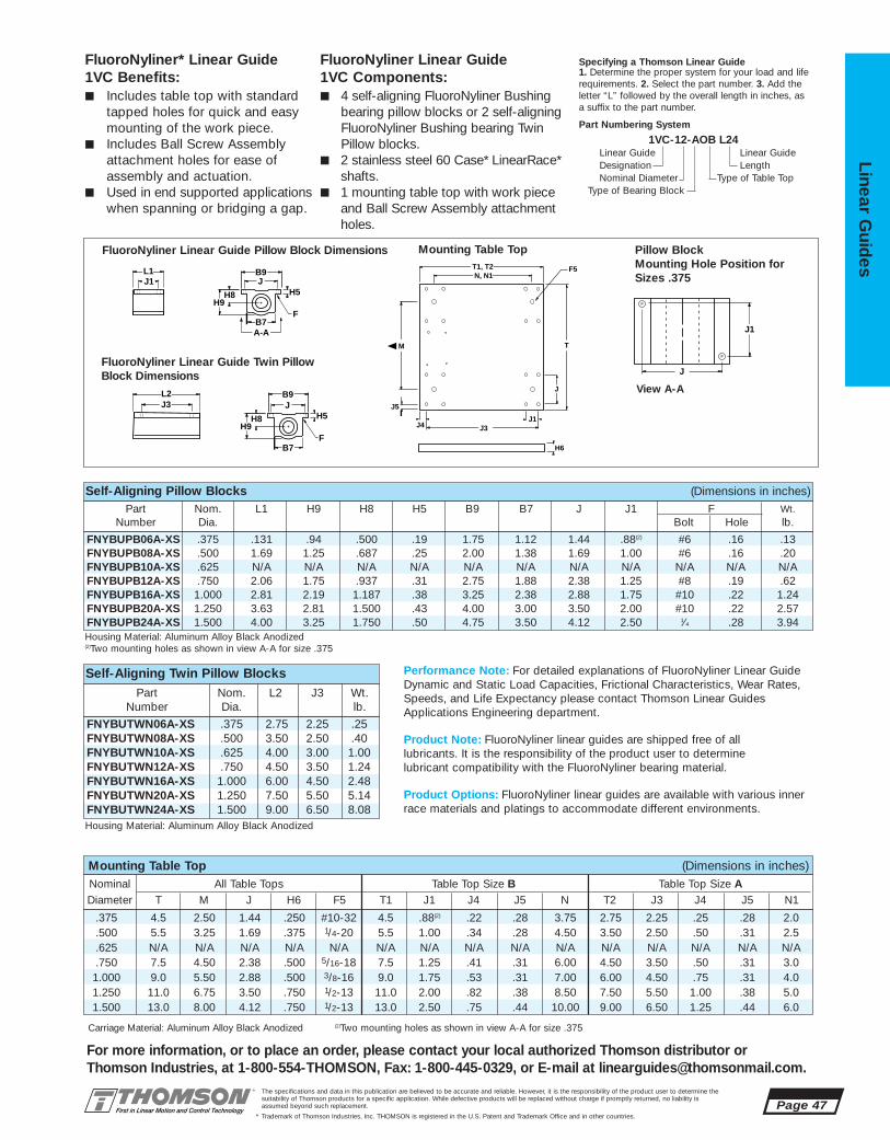
.375 4.5 2.50 1.44 .250 #10-32 4.5 .88(2) .22 .28 3.75 2.75 2.25 .25 .28 2.0
.500 5.5 3.25 1.69 .375 1/4-20 5.5 1.00 .34 .28 4.50 3.50 2.50 .50 .31 2.5
.625 N/A N/A N/A N/A N/A N/A N/A N/A N/A N/A N/A N/A N/A N/A N/A
.750 7.5 4.50 2.38 .500 5/16-18 7.5 1.25 .41 .31 6.00 4.50 3.50 .50 .31 3.01.000 9.0 5.50 2.88 .500 3/8-16 9.0 1.75 .53 .31 7.00 6.00 4.50 .75 .31 4.01.250 11.0 6.75 3.50 .750 1/2-13 11.0 2.00 .82 .38 8.50 7.50 5.50 1.00 .38 5.01.500 13.0 8.00 4.12 .750 1/2-13 13.0 2.50 .75 .44 10.00 9.00 6.50 1.25 .44 6.0
FNYBUTWN06A-XS .375 2.75 2.25 .25FNYBUTWN08A-XS .500 3.50 2.50 .40FNYBUTWN10A-XS .625 4.00 3.00 1.00FNYBUTWN12A-XS .750 4.50 3.50 1.24FNYBUTWN16A-XS 1.000 6.00 4.50 2.48FNYBUTWN20A-XS 1.250 7.50 5.50 5.14FNYBUTWN24A-XS 1.500 9.00 6.50 8.08
FNYBUPB06A-XS .375 .131 .94 .500 .19 1.75 1.12 1.44 .88(2) #6 .16 .13FNYBUPB08A-XS .500 1.69 1.25 .687 .25 2.00 1.38 1.69 1.00 #6 .16 .20FNYBUPB10A-XS .625 N/A N/A N/A N/A N/A N/A N/A N/A N/A N/A N/AFNYBUPB12A-XS .750 2.06 1.75 .937 .31 2.75 1.88 2.38 1.25 #8 .19 .62FNYBUPB16A-XS 1.000 2.81 2.19 1.187 .38 3.25 2.38 2.88 1.75 #10 .22 1.24FNYBUPB20A-XS 1.250 3.63 2.81 1.500 .43 4.00 3.00 3.50 2.00 #10 .22 2.57FNYBUPB24A-XS 1.500 4.00 3.25 1.750 .50 4.75 3.50 4.12 2.50 1⁄4 .28 3.94
The specifications and data in this publication are believed to be accurate and reliable. However, it is the responsibility of the product user to determine thesuitability of Thomson products for a specific application. While defective products will be replaced without charge if promptly returned, no liability is assumed beyond such replacement.
* Trademark of Thomson Industries, Inc. THOMSON is registered in the U.S. Patent and Trademark Office and in other countries.
Linear Guid
es
Page 47
For more information, or to place an order, please contact your local authorized Thomson distributor orThomson Industries, at 1-800-554-THOMSON, Fax: 1-800-445-0329, or E-mail at [email protected].
View A-A
FluoroNyliner Linear Guide1VC Components:■ 4 self-aligning FluoroNyliner Bushing
bearing pillow blocks or 2 self-aligningFluoroNyliner Bushing bearing TwinPillow blocks.
■ 2 stainless steel 60 Case* LinearRace*shafts.
■ 1 mounting table top with work pieceand Ball Screw Assembly attachmentholes.
FluoroNyliner* Linear Guide 1VC Benefits:■ Includes table top with standard
tapped holes for quick and easy mounting of the work piece.
■ Includes Ball Screw Assembly attachment holes for ease of assembly and actuation.
■ Used in end supported applications when spanning or bridging a gap.
Specifying a Thomson Linear Guide1. Determine the proper system for your load and liferequirements. 2. Select the part number. 3. Add theletter “L” followed by the overall length in inches, asa suffix to the part number.
Part Numbering System
1VC-12-AOB L24Linear Guide Linear GuideDesignation LengthNominal Diameter Type of Table Top
Type of Bearing Block
Carriage Material: Aluminum Alloy Black Anodized (2)Two mounting holes as shown in view A-A for size .375
Mounting Table Top (Dimensions in inches)
B9
A-A
H8 H5H9
B7
L1 J1 J
F
J3B9
H8 H9
L2 J
H5
B7 F
J
J5
H6
M
N, N1 T1, T2
J3J1
F5
T
J4
J
J1
Pillow BlockMounting Hole Position forSizes .375
FluoroNyliner Linear Guide Pillow Block Dimensions
FluoroNyliner Linear Guide Twin Pillow Block Dimensions
Mounting Table Top
Nominal All Table Tops Table Top Size B Table Top Size ADiameter T M J H6 F5 T1 J1 J4 J5 N T2 J3 J4 J5 N1
Self-Aligning Pillow Blocks (Dimensions in inches)
Part Nom. L2 J3 Wt.Number Dia. lb.
Housing Material: Aluminum Alloy Black Anodized(2)Two mounting holes as shown in view A-A for size .375
Housing Material: Aluminum Alloy Black Anodized
Self-Aligning Twin Pillow Blocks
Part Nom. L1 H9 H8 H5 B9 B7 J J1 F Wt.Number Dia. Bolt Hole lb.
Performance Note: For detailed explanations of FluoroNyliner Linear GuideDynamic and Static Load Capacities, Frictional Characteristics, Wear Rates,Speeds, and Life Expectancy please contact Thomson Linear GuidesApplications Engineering department.
Product Note: FluoroNyliner linear guides are shipped free of all lubricants. It is the responsibility of the product user to determinelubricant compatibility with the FluoroNyliner bearing material.
Product Options: FluoroNyliner linear guides are available with various innerrace materials and platings to accommodate different environments.

1VA-06-BHO – .375 2.75 .56 1.062 – 1.63 – 1.75 L-(3.88) FNYBUTWN06A-XS ASB-6-XS –
1VA-08-BHO 1VA-08-BJO .500 3.50 .63 1.562 1.687 2.00 2.00 2.00 L-(4.75) FNYBUTWN08A-XS ASB-8-XS SB-8-XS
– 1VA-10-BJO .625 4.00 .69 – 1.875 – 2.50 2.50 L-(5.38) FNYBUTWN10A-XS – SB-10-XS
1VA-12-BHO 1VA-12-BJO .750 4.50 .75 2.062 2.187 2.50 2.75 2.75 L-(6.00) FNYBUTWN12A-XS ASB-12-XS SB-12-XS
1VA-16-BHO 1VA-16-BJO 1.000 6.00 1.00 2.562 2.687 3.25 3.25 3.25 L-(8.00) FNYBUTWN16A-XS ASB-16-XS SB-16-XS
– 1VA-20-BJO 1.250 7.50 1.13 – 3.250 – 4.00 4.00 L-(9.75) FNYBUTWN20A-XS – SB-20-XS
1VA-24-BHO 1VA-24-BJO 1.500 9.00 1.25 3.750 3.750 4.75 4.75 4.75 L-(11.50) FNYBUTWN24A-XS ASB-24-XS SB-24-XS
1VA-06-AHO – .375 1.31 .56 1.062 – 1.63 – 1.75 FNYBUPB06A-XS ASB-6-XS –
1VA-08-AHO 1VA-08-AJO .500 1.69 .63 1.562 1.687 2.00 2.00 2.00 FNYBUPB08A-XS ASB-8-XS SB-8-XS
– 1VA-10-AJO .625 1.94 .67 – 1.875 – 2.50 2.50 FNYBUPB10A-XS SB-10-XS
1VA-12-AHO 1VA-12-AJO .750 2.06 .75 2.062 2.187 2.50 2.75 2.75 FNYBUPB12A-XS ASB-12-XS SB-12-XS
1VA-16-AHO 1VA-16-AJO 1.000 2.81 1.00 2.562 2.687 3.25 3.25 3.25 FNYBUPB16A-XS ASB-16-XS SB-16-XS
– 1VA-20-AJO 1.250 3.63 1.13 – 3.250 – – 4.00 FNYBUPB20A-XS – SB-20-XS
1VA-24-AHO 1VA-24-AJO 1.500 4.00 1.25 3.750 3.750 4.75 4.75 4.75 FNYBUPB24A-XS ASB-24-XS SB-24-XS
Page 48The specifications and data in this publication are believed to be accurate and reliable. However, it is the responsibility of the product user to determine thesuitability of Thomson products for a specific application. While defective products will be replaced without charge if promptly returned, no liability is assumed beyond such replacement.
* Trademark of Thomson Industries, Inc. THOMSON is registered in the U.S. Patent and Trademark Office and in other countries.
Line
ar G
uid
es
For more information, or to place an order, please contact your local authorized Thomson distributor orThomson Industries, at 1-800-554-THOMSON, Fax: 1-800-445-0329, or E-mail at [email protected].
FluoroNyliner 1VALinear Guide #5Corrosive/ContaminatedEnvironments
L2
L1 L3
B9
H
L
L
B
Bb
HS
L3
FluoroNyliner* Linear Guide 1VA Single End Supported with 2 Pillow Blocks (Dimensions in inches)Part Number Nominal L1 L3 H HS B Bb B9 Pillow Shaft Support
W/ Type ASB W/ Type SB Diameter Block Type TypeShaft Shaft ASB SB
Support Support
FluoroNyliner Linear Guide 1VA Single End Supported with 1 Twin Pillow Block (Dimensions in inches)Part Number Nom. L2 L3 H HS B Bb B9 Max. Pillow Shaft Support
W/ Type ASB W/ Type SB Dia. Stroke Block Type TypeShaft Shaft Length ASB SB
Support Support
Single End Supported Linear Guide with 2 Pillow Blocks
Single End Supported Linear Guide with 1 Twin Pillow Block
Linear Guide 1VA with Type SBEnd Support Block
INCH
Maximum Operating Parameters per BearingCharacteristic Limit
Liner Temperature Range
Velocity, dry
Velocity, dry
Velocity, lubricated
Pressure
PV
-240˚ C to 288˚ C (-400˚ F to 550˚ F)
42.7 m/min. Continuous
122 m/min. Intermittent
122 m/min. Continuous
10.35 MPa
21 MPa/m/min
Shaft Deflection Note:Load limit may be below the dynamic load rating due to shaftdeflection. Bearings can accommodate up to 1/2º deflection. See Engineering Section (pg 204) for deflection calculations.

SB-8-XS .500 .63 1.62 1.000 2.00 1.50 #8 .19 .3SB-10-XS .625 .69 1.75 1.00 2.50 1.875 #10 .22 .4SB-12-XS .750 .75 2.12 1.250 2.75 2.00 #10 .22 .5SB-16-XS 1.000 1.00 2.56 1.500 3.25 2.50 1⁄4 .28 1.0SB-20-XS 1.250 1.13 3.00 1.750 4.00 3.00 5⁄16 .34 2.0SB-24-XS 1.500 1.25 3.50 2.000 4.75 3.50 5⁄16 .34 2.6
ASB-06-XS .375 .56 1.00 .562 1.62 1.25 #6 .16 .08ASB-08-XS .500 .63 1.48 .875 2.00 1.50 #8 .19 .11ASB-10-XS .625 – – – – – – – –ASB-12-XS .750 .75 1.95 1.125 2.50 2.00 #10 .22 .22ASB-16-XS 1.000 1.00 2.48 1.375 3.25 2.50 1⁄4 .28 .44ASB-24-XS 1.500 1.250 3.50 2.000 4.75 3.50 5⁄16 .34 1.16
FNYBUTWN06A-XS .375 2.75 2.25 .25FNYBUTWN08A-XS .500 3.50 2.50 .40FNYBUTWN10A-XS .625 4.00 3.00 1.00FNYBUTWN12A-XS .750 4.50 3.50 1.24FNYBUTWN16A-XS 1.000 6.00 4.50 2.48FNYBUTWN20A-XS 1.250 7.50 5.50 5.14FNYBUTWN24A-XS 1.500 9.00 6.50 8.08
FNYBUPB06A-XS .375 .131 .94 .500 .19 1.75 1.12 1.44 .88(2) #6 .16 .13FNYBUPB08A-XS .500 1.69 1.25 .687 .25 2.00 1.38 1.69 1.00 #6 .16 .20FNYBUPB10A-XS .625 1.94 1.63 .875 .28 2.50 1.75 2.125 1.125 #8 .19 .50FNYBUPB12A-XS .750 2.06 1.75 .937 .31 2.75 1.88 2.38 1.25 #8 .19 .62FNYBUPB16A-XS 1.000 2.81 2.19 1.187 .38 3.25 2.38 2.88 1.75 #10 .22 1.24FNYBUPB20A-XS 1.250 3.63 2.81 1.500 .43 4.00 3.00 3.50 2.00 #10 .22 2.57FNYBUPB24A-XS 1.500 4.00 3.25 1.750 .50 4.75 3.50 4.12 2.50 1⁄4 .28 3.94
The specifications and data in this publication are believed to be accurate and reliable. However, it is the responsibility of the product user to determine thesuitability of Thomson products for a specific application. While defective products will be replaced without charge if promptly returned, no liability is assumed beyond such replacement.
* Trademark of Thomson Industries, Inc. THOMSON is registered in the U.S. Patent and Trademark Office and in other countries.
Linear Guid
es
Page 49
For more information, or to place an order, please contact your local authorized Thomson distributor orThomson Industries, at 1-800-554-THOMSON, Fax: 1-800-445-0329, or E-mail at [email protected].
Specifying a Thomson Linear Guide1. Determine the proper system for your load andlife requirements. 2. Select the part number. 3. Addthe letter “L” followed by the overall length ininches, as a suffix to the part number.
Part Numbering System
1VA-12-AHO L24Linear Guide Linear GuideDesignation LengthNominal Diameter
Type of Bearing Block Type of Support
J3B9
H8 H9
L2 J
H5
B7 F
B9
A-A
H8 H5H9
B7
L1 J1 J
F
End Support Material: Aluminum Alloy Black Anodized Material: Iron
FluoroNyliner Linear Guide 1VA Benefits:■ Requires only one part number to
specify entire linear guide.■ Available with 60 Case* LinearRace*
shaft end support blocks in either light weight aluminum or rigid iron materials.
■ Used to provide increased stability or torque resistance in linear systemapplications.
FluoroNyliner Linear Guide 1VA Components:■ 2 self-aligning FluoroNyliner Bushing
bearing pillow blocks or 1 self-aligning FluoroNyliner Bushingbearing twin pillow block.
■ 1 stainless steel 60 Case LinearRaceshaft.
■ 2 shaft end support blocks.
J
J1
Type ASB LinearRace Shaft End Support Block Type SB LinearRace Shaft End Support BlockPart Nom. L3 H3 H1 B B3 G Wt.
Number Dia. Bolt Hole lb
Part Nom. L3 Hh Hc Bb B3 G Wt.Number Dia. Bolt Hole lb
G G
Bb Bb
H3 H1 Hc Hh
B B3 B3 L3
Pillow BlockMounting Hole Position forSize .375
FluoroNyliner Linear Guide Pillow Block Dimensions
Type ASB LinearRaceShaft End Support Block
Type SB LinearRaceShaft End Support Block
FluoroNyliner Linear Guide Twin Pillow Block Dimensions
View A-A
Self-Aligning Pillow Blocks (Dimensions in inches)
Part Nom. L2 J3 Wt.Number Dia. lb.
Housing Material: Aluminum Alloy Black Anodized(2)Two mounting holes as shown in view A-A for size .375
Housing Material: Aluminum Alloy Black Anodized
Self-Aligning Twin Pillow Blocks
Part Nom. L1 H9 H8 H5 B9 B7 J J1 F Wt.Number Dia. Bolt Hole lb
Performance Note: For detailed explanations of FluoroNyliner Linear GuideDynamic and Static Load Capacities, Frictional Characteristics, Wear Rates,Speeds, and Life Expectancy please contact Thomson Linear GuidesApplications Engineering department.
Product Note: FluoroNyliner linear guides are shipped free of all lubricants. It is the responsibility of the product user to determine lubricantcompatibility with the FluoroNyliner bearing material.
Product Options: FluoroNyliner linear guides are available with various innerrace materials and platings to accommodate different environments.

1VB-06-AHO – .375 1.31 .56 1.062 – 1.63 – 1.75 FNYBUPB06A-XS ASB-6-XS –
1VB-08-AHO 1VB-08-AJO .500 1.69 .63 1.562 1.687 2.00 2.00 2.00 FNYBUPB08A-XS ASB-8-XS SB-8-XS
– 1VB-10-AJO .625 1.94 .69 – 1.875 – 2.50 2.50 FNYBUPB10A-XS – SB-10-XS
1VB-12-AHO 1VB-12-AJO .750 2.06 .75 2.062 2.187 2.50 2.75 2.75 FNYBUPB12A-XS ASB-12-XS SB-12-XS
1VB-16-AHO 1VB-16-AJO 1.000 2.81 1.00 2.562 2.687 3.25 3.25 3.25 FNYBUPB16A-XS ASB-16-XS SB-16-XS
– 1VB-20-AJO 1.250 3.63 1.13 – 3.250 – – 4.00 FNYBUPB20A-XS – SB-20-XS
1VB-24-AHO 1VB-24-AJO 1.500 4.00 1.25 3.750 3.750 4.75 4.75 4.75 FNYBUPB24A-XS ASB-24-XS SB-24-XS
1VB-06-BHO – .375 2.75 .56 1.062 – 1.63 – 1.75 L-(3.88) FNYBUTWN06A-XS ASB-6-XS –
1VB-08-BHO 1VB-08-BJO .500 3.50 .63 1.562 1.687 2.00 2.00 2.00 L-(4.75) FNYBUTWN08A-XS ASB-8-XS SB-8-XS
– 1VB-10-BJO .625 4.00 .69 – 1.875 – 2.50 2.50 L-(5.38) FNYBUTWN10A-XS – SB-10-XS
1VB-12-BHO 1VB-12-BJO .750 4.50 .75 2.062 2.187 2.50 2.75 2.75 L-(6.00) FNYBUTWN12A-XS ASB-12-XS SB-12-XS
1VB-16-BHO 1VB-16-BJO 1.000 6.00 1.00 2.562 2.687 3.25 3.25 3.25 L-(8.00) FNYBUTWN16A-XS ASB-16-XS SB-16-XS
– 1VB-20-BJO 1.250 7.50 1.13 – 3.250 – 4.00 4.00 L-(9.75) FNYBUTWN20A-XS – SB-20-XS
1VB-24-BHO 1VB-24-BJO 1.500 9.00 1.25 3.750 3.750 4.75 4.75 4.75 L-(11.50) FNYBUTWN24A-XS ASB-24-XS SB-24-XS
Page 50The specifications and data in this publication are believed to be accurate and reliable. However, it is the responsibility of the product user to determine thesuitability of Thomson products for a specific application. While defective products will be replaced without charge if promptly returned, no liability is assumed beyond such replacement.
* Trademark of Thomson Industries, Inc. THOMSON is registered in the U.S. Patent and Trademark Office and in other countries.
Line
ar G
uid
es
For more information, or to place an order, please contact your local authorized Thomson distributor orThomson Industries, at 1-800-554-THOMSON, Fax: 1-800-445-0329, or E-mail at [email protected].
FluoroNyliner 1VBLinear Guide #5Corrosive/ContaminatedEnvironments
Bb
HS
B9
H
B
H1
L1 L3
L
L2
L
L3
Double End Supported Linear Guide with 4 Pillow Blocks
Double End Supported Linear Guide with 2 Twin Pillow Blocks
Linear Guide 1VB with Type SBEnd Support Block
FluoroNyliner* Linear Guide 1VB Double End Supported with 4 Pillow Blocks (Dimensions in inches)Part Number Nominal L1 L3 H HS B Bb B9 Pillow Shaft Support
W/ Type ASB W/ Type SB Diameter Block Type TypeShaft Shaft ASB SB
Support Support
FluoroNyliner Linear Guide 1VB Double End Supported with 2 Twin Pillow Blocks (Dimensions in inches)Part Number Nom. L2 L3 H HS B Bb B9 Max. Pillow Shaft Support
W/ Type ASB W/ Type SB Dia. Stroke Block Type TypeShaft Shaft Length ASB SB
Support Support
INCH
Maximum Operating Parameters per BearingCharacteristic Limit
Liner Temperature Range
Velocity, dry
Velocity, dry
Velocity, lubricated
Pressure
PV
-240˚ C to 288˚ C (-400˚ F to 550˚ F)
42.7 m/min. Continuous
122 m/min. Intermittent
122 m/min. Continuous
10.35 MPa
21 MPa/m/min
Shaft Deflection Note:Load limit may be below the dynamic load rating due to shaft deflection. Bearings can accommodate up to 1/2º deflection. See Engineering Section (pg 204) for deflection calculations.
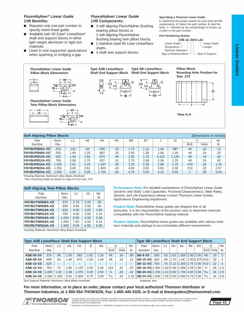
FNYBUTWN06A-XS .375 2.75 2.25 .25FNYBUTWN08A-XS .500 3.50 2.50 .40FNYBUTWN10A-XS .625 4.00 3.00 1.00FNYBUTWN12A-XS .750 4.50 3.50 1.24FNYBUTWN16A-XS 1.000 6.00 4.50 2.48FNYBUTWN20A-XS 1.250 7.50 5.50 5.14FNYBUTWN24A-XS 1.500 9.00 6.50 8.08
SB-8-XS .500 .63 1.62 1.000 2.00 1.50 #8 .19 .3SB-10-XS .625 .69 1.75 1.00 2.50 1.875 #10 .22 .4SB-12-XS .750 .75 2.12 1.250 2.75 2.00 #10 .22 .5SB-16-XS 1.000 1.00 2.56 1.500 3.25 2.50 1⁄4 .28 1.0SB-20-XS 1.250 1.13 3.00 1.750 4.00 3.00 5⁄16 .34 2.0SB-24-XS 1.500 1.25 3.50 2.000 4.75 3.50 5⁄16 .34 2.6
ASB-06-XS .375 .56 1.00 .562 1.62 1.25 #6 .16 .08ASB-08-XS .500 .63 1.48 .875 2.00 1.50 #8 .19 .11ASB-10-XS .625 – – – – – – – –ASB-12-XS .750 .75 1.95 1.125 2.50 2.00 #10 .22 .22ASB-16-XS 1.000 1.00 2.48 1.375 3.25 2.50 1⁄4 .28 .44ASB-24-XS 1.500 1.250 3.50 2.000 4.75 3.50 5⁄16 .34 1.16
FNYBUPB06A-XS .375 .131 .94 .500 .19 1.75 1.12 1.44 .88(2) #6 .16 .13FNYBUPB08A-XS .500 1.69 1.25 .687 .25 2.00 1.38 1.69 1.00 #6 .16 .20FNYBUPB10A-XS .625 1.94 1.63 .875 .28 2.50 1.75 2.125 1.125 #8 .19 .50FNYBUPB12A-XS .750 2.06 1.75 .937 .31 2.75 1.88 2.38 1.25 #8 .19 .62FNYBUPB16A-XS 1.000 2.81 2.19 1.187 .38 3.25 2.38 2.88 1.75 #10 .22 1.24FNYBUPB20A-XS 1.250 3.63 2.81 1.500 .43 4.00 3.00 3.50 2.00 #10 .22 2.57FNYBUPB24A-XS 1.500 4.00 3.25 1.750 .50 4.75 3.50 4.12 2.50 1⁄4 .28 3.94
The specifications and data in this publication are believed to be accurate and reliable. However, it is the responsibility of the product user to determine thesuitability of Thomson products for a specific application. While defective products will be replaced without charge if promptly returned, no liability is assumed beyond such replacement.
* Trademark of Thomson Industries, Inc. THOMSON is registered in the U.S. Patent and Trademark Office and in other countries.
Linear Guid
es
Page 51
For more information, or to place an order, please contact your local authorized Thomson distributor orThomson Industries, at 1-800-554-THOMSON, Fax: 1-800-445-0329, or E-mail at [email protected].
Specifying a Thomson Linear Guide:1. Determine the proper system for your load and liferequirements. 2. Select the part number. 3. Add theletter “L” followed by the overall length in inches, asa suffix to the part number.
Part Numbering System
1VB-12-AHO L24Linear Guide Linear GuideDesignation LengthNominal Diameter
Type of Bearing Block Type of Support
FluoroNyliner* Linear Guide 1VB Benefits:■ Requires only one part number to
specify entire linear guide.■ Available with 60 Case* LinearRace*
shaft end support blocks in either light weight aluminum or rigid iron materials.
■ Used in end supported applications when spanning or bridging a gap.
FluoroNyliner Linear Guide 1VB Components:■ 4 self-aligning FluoroNyliner Bushing
bearing pillow blocks or 2 self-aligning FluoroNyliner Bushing bearing twin pillow blocks.
■ 2 stainless steel 60 Case LinearRaceshafts.
■ 4 shaft end support blocks.
End Support Material: Aluminum Alloy Black Anodized
Type ASB LinearRace Shaft End Support BlockPart Nom. L3 H3 H1 B B3 G Wt.
Number Dia. Bolt Hole lb
J3B9
H8 H9
L2 J
H5
B7 F
B9
A-A
H8 H5H9
B7
L1 J1 J
F
J
J1
G G
Bb Bb
H3 H1 Hc Hh
B B3 B3 L3
Pillow BlockMounting Hole Position forSize .375
FluoroNyliner Linear Guide Pillow Block Dimensions
Type ASB LinearRaceShaft End Support Block
Type SB LinearRaceShaft End Support Block
FluoroNyliner Linear Guide Twin Pillow Block Dimensions
View A-A
Material: Iron
Type SB LinearRace Shaft End Support BlockPart Nom. L3 Hh Hc Bb B3 G Wt.
Number Dia. Bolt Hole lb
Self-Aligning Pillow Blocks (Dimensions in inches)
Part Nom. L2 J3 Wt.Number Dia. lb
Housing Material: Aluminum Alloy Black Anodized(2)Two mounting holes as shown in view A-A for size .375
Housing Material: Aluminum Alloy Black Anodized
Self-Aligning Twin Pillow Blocks
Part Nom. L1 H9 H8 H5 B9 B7 J J1 F Wt.Number Dia. Bolt Hole lb
Performance Note: For detailed explanations of FluoroNyliner Linear GuideDynamic and Static Load Capacities, Frictional Characteristics, Wear Rates,Speeds, and Life Expectancy please contact Thomson Linear GuidesApplications Engineering department.
Product Note: FluoroNyliner linear guides are shipped free of all lubricants. It is the responsibility of the product user to determine lubricantcompatibility with the FluoroNyliner bearing material.
Product Options: FluoroNyliner linear guides are available with various innerrace materials and platings to accommodate different environments.
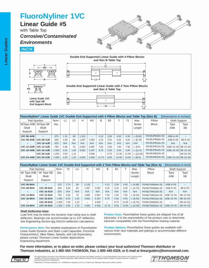
1VC-06-AHB – .375 1.31 .56 1.312 – 4.13 2.50 4.50 4.50 L-(5.62) FNYBUPB06A-XS ASB-6-XS –
1VC-08-AHB 1VC-08-AJB .500 1.69 .63 1.937 2.062 5.25 3.25 5.50 5.50 L-(6.76) FNYBUPB08A-XS ASB-8-XS SB-8-XS
– 1VC-10-AJB .625 N/A N/A N/A N/A N/A N/A N/A N/A N/A FNYBUPB10A-XS N/A N/A
1VC-12-AHB 1VC-12-AJB .750 2.06 .75 2.562 2.687 7.00 4.50 7.50 7.50 L-(9.0) FNYBUPB12A-XS ASB-12-XS SB-12-XS
1VC-16-AHB 1VC-16-AJB 1.000 2.81 1.00 3.062 3.187 8.75 5.50 9.00 9.00 L-(11.0) FNYBUPB16A-XS ASB-16-XS SB-16-XS
– 1VC-20-AJB 1.250 3.63 1.13 – 4.000 – 6.75 11.00 11.00 L-(13.26) FNYBUPB20A-XS – SB-20-XS
1VC-24-AHB 1VC-24-AJB 1.500 4.00 1.25 4.500 4.500 12.75 8.00 13.00 13.00 L-(15.5) FNYBUPB24A-XS ASB-24-XS SB-24-XS
1VC-06-BHA – .375 2.75 .56 1.132 – 4.13 2.50 4.50 L-(3.88) FNYBUTWN06A-XS ASB-6-XS –
1VC-08-BHA 1VC-08-BJA .500 3.50 .63 1.937 2.062 5.25 3.25 5.50 L-(4.75) FNYBUTWN08A-XS ASB-8-XS SB-8-XS
– 1VC-10-BJA .625 N/A N/A N/A N/A N/A N/A N/A N/A FNYBUTWN10A-XS N/A N/A
1VC-12-BHA 1VC-12-BJA .750 4.50 .75 2.562 2.687 7.00 4.50 7.50 L-(6.00) FNYBUTWN12A-XS ASB-12-XS SB-12-XS
1VC-16-BHA 1VC-16-BJA 1.000 6.00 1.00 3.062 3.187 8.75 5.50 9.00 L-(8.00) FNYBUTWN16A-XS ASB-16-XS SB-16-XS
– 1VC-20-BJA 1.250 7.50 1.13 – 4.000 – 6.75 11.00 L-(9.75) FNYBUTWN20A-XS – SB-20-XS
1VC-24-BHA 1VC-24-BJA 1.500 9.00 1.25 4.500 4.500 12.75 8.00 13.00 L-(11.50) FNYBUTWN24A-XS ASB-24-XS SB-24-XS
Page 52The specifications and data in this publication are believed to be accurate and reliable. However, it is the responsibility of the product user to determine thesuitability of Thomson products for a specific application. While defective products will be replaced without charge if promptly returned, no liability is assumed beyond such replacement.
* Trademark of Thomson Industries, Inc. THOMSON is registered in the U.S. Patent and Trademark Office and in other countries.
Line
ar G
uid
es
For more information, or to place an order, please contact your local authorized Thomson distributor orThomson Industries, at 1-800-554-THOMSON, Fax: 1-800-445-0329, or E-mail at [email protected].
FluoroNyliner 1VCLinear Guide #5with Table Top
Corrosive/ContaminatedEnvironments
T2
T1
L1
L
L
HS
B2T
H
B L3
L3
FluoroNyliner* Linear Guide 1VC Double End Supported with 4 Pillow Blocks and Table Top (Size B) (Dimensions in inches)Part Number Nom. L1 L3 H HS B B2 T T1 Max. Pillow Shaft Support
W/Type ASB W/Type SB Dia. Stroke Block Type TypeShaft Shaft Length ASB SB
Support Support
FluoroNyliner Linear Guide 1VC Double End Supported with 2 Twin Pillow Blocks and Table Top (Size A) (Dimensions in inch)Part Number Nom. T2 L3 H HS B B2 T Max. Pillow Shaft Support
W/ Type ASB W/ Type SB Dia. Stroke Block Type TypeShaft Shaft Length ASB SB
Support Support
Double End Supported Linear Guide with 4 Pillow Blocks and Size B Table Top
Double End Supported Linear Guide with 2 Twin Pillow Blocks and Size A Table Top
Linear Guide 1VC with Type SBEnd Support Block
Performance Note: For detailed explanations of FluoroNylinerLinear Guide Dynamic and Static Load Capacities, FrictionalCharacteristics, Wear Rates, Speeds, and Life Expectancyplease contact Thomson Linear Guides ApplicationsEngineering department.
Product Note: FluoroNyliner linear guides are shipped free of all lubricants. It is the responsibility of the product user to determinelubricant compatibility with the FluoroNyliner bearing material.
Product Options: FluoroNyliner linear guides are available with various inner race materials and platings to accommodate differentenvironments.
INCH
Shaft Deflection Note:Load limit may be below the dynamic load rating due to shaft deflection. Bearings can accommodate up to 1/2º deflection. See Engineering Section (pg 204) for deflection calculations.

.375 4.5 2.50 1.44 .250 #10-32 4.5 .88(2) .22 .28 3.75 2.75 2.25 .25 .28 2.0
.500 5.5 3.25 1.69 .375 1/4-20 5.5 1.00 .34 .28 4.50 3.50 2.50 .50 .31 2.5
.625 N/A N/A N/A N/A N/A N/A N/A N/A N/A N/A N/A N/A N/A N/A N/A
.750 7.5 4.50 2.38 .500 5/16-18 7.5 1.25 .41 .31 6.00 4.50 3.50 .50 .31 3.01.000 9.0 5.50 2.88 .500 3/8-16 9.0 1.75 .53 .31 7.00 6.00 4.50 .75 .31 4.01.250 11.0 6.75 3.50 .750 1/2-13 11.0 2.00 .82 .38 8.50 7.50 5.50 1.00 .38 5.01.500 13.0 8.00 4.12 .750 1/2-13 13.0 2.50 .75 .44 10.00 9.00 6.50 1.25 .44 6.0
SB-8-XS .500 .63 1.62 1.000 2.00 1.50 #8 .19 .3SB-10-XS .625 .69 1.75 1.00 2.50 1.875 #10 .22 .4SB-12-XS .750 .75 2.12 1.250 2.75 2.00 #10 .22 .5SB-16-XS 1.000 1.00 2.56 1.500 3.25 2.50 1⁄4 .28 1.0SB-20-XS 1.250 1.13 3.00 1.750 4.00 3.00 5⁄16 .34 2.0SB-24-XS 1.500 1.25 3.50 2.000 4.75 3.50 5⁄16 .34 2.6
ASB-06-XS .375 .56 1.00 .562 1.62 1.25 #6 .16 .08ASB-08-XS .500 .63 1.48 .875 2.00 1.50 #8 .19 .11ASB-10-XS .625 – – – – – – – –ASB-12-XS .750 .75 1.95 1.125 2.50 2.00 #10 .22 .22ASB-16-XS 1.000 1.00 2.48 1.375 3.25 2.50 1⁄4 .28 .44ASB-24-XS 1.500 1.250 3.50 2.000 4.75 3.50 5⁄16 .34 1.16
FNYBUTWN06A-XS .375 2.75 2.25 .25FNYBUTWN08A-XS .500 3.50 2.50 .40FNYBUTWN10A-XS .625 – – –FNYBUTWN12A-XS .750 4.50 3.50 1.24FNYBUTWN16A-XS 1.000 6.00 4.50 2.48FNYBUTWN20A-XS 1.250 7.50 5.50 5.14FNYBUTWN24A-XS 1.500 9.00 6.50 8.08
FNYBUPB06A-XS .375 .131 .94 .500 .19 1.75 1.12 1.44 .88(2) #6 .16 .13FNYBUPB08A-XS .500 1.69 1.25 .687 .25 2.00 1.38 1.69 1.00 #6 .16 .20FNYBUPB10A-XS .625 – – – – – – – – – – –FNYBUPB12A-XS .750 2.06 1.75 .937 .31 2.75 1.88 2.38 1.25 #8 .19 .62FNYBUPB16A-XS 1.000 2.81 2.19 1.187 .38 3.25 2.38 2.88 1.75 #10 .22 1.24FNYBUPB20A-XS 1.250 3.63 2.81 1.500 .43 4.00 3.00 3.50 2.00 #10 .22 2.57FNYBUPB24A-XS 1.500 4.00 3.25 1.750 .50 4.75 3.50 4.12 2.50 1⁄4 .28 3.94
The specifications and data in this publication are believed to be accurate and reliable. However, it is the responsibility of the product user to determine thesuitability of Thomson products for a specific application. While defective products will be replaced without charge if promptly returned, no liability is assumed beyond such replacement.
* Trademark of Thomson Industries, Inc. THOMSON is registered in the U.S. Patent and Trademark Office and in other countries.
Linear Guid
es
Page 53
For more information, or to place an order, please contact your local authorized Thomson distributor orThomson Industries, at 1-800-554-THOMSON, Fax: 1-800-445-0329, or E-mail at [email protected].
Specifying a Thomson Linear Guide:1. Determine the proper system for your load andlife requirements. 2. Select the part number. 3. Addthe letter “L” followed by the overall length in inches, as a suffix to the part number.
Part Numbering System
1VC-12-AHB L24Linear Guide Linear GuideDesignation LengthNominal Diameter Type of Table Top
Type of Bearing Block Type of Support
J
J1
FluoroNyliner* Linear Guide 1VC Benefits:■ Includes table top with standard tapped
holes for quick and easy mounting of thework piece.
■ Includes Ball Screw Assembly attachmentholes for ease of assembly and actuation.
■ Available with 60 Case* LinearRace* shaftend support blocks in either light weightaluminum or rigid iron materials.
FluoroNyliner Linear Guide 1VC Components:■ 4 self-aligning FluoroNyliner Bushing
bearing pillow blocks or 2 self-aligningFluoroNyliner Bushing bearing twin pillowblocks.
■ 2 Stainless Steel 60 Case LinearRaceshafts.
■ 4 Shaft End Support Blocks.■ 1 mounting table top with work piece and
Ball Screw Assembly attachment holes.
J
J5
H6
M
N, N1 T1, T2
J3J1
F5
T
J4
G H3 H1
B B3 L3
G
Bb Bb
Hc Hh
B3
Pillow BlockMounting Hole Position forSize .375
FluoroNyliner Linear Guide Pillow Block Dimensions
Type ASB LinearRaceShaft End Support Block
Type SB LinearRaceShaft End Support Block
FluoroNyliner Linear Guide Twin Pillow Block Dimensions
View A-A
Mounting Table Top
End Support Material: Aluminum Alloy Black Anodized
Type ASB LinearRace Shaft End Support BlockPart Nom. L3 H3 H1 B B3 G Wt.
Number Dia. Bolt Hole lb
J3B9
H8 H9
L2 J
H5
B7 F
B9
A-A
H8 H5H9
B7
L1 J1 J
F
Self-Aligning Pillow Blocks (Dimensions in inches)Part Nom. L2 J3 Wt.
Number Dia. lb.
Housing Material: Aluminum Alloy Black Anodized(2)Two mounting holes as shown in view A-A for size .375
Housing Material: Aluminum Alloy Black Anodized
Self-Aligning Twin Pillow BlocksPart Nom. L1 H9 H8 H5 B9 B7 J J1 F Wt.
Number Dia. Bolt Hole lb
Material: Iron
Type SB LinearRace Shaft End Support BlockPart Nom. L3 Hh Hc Bb B3 G Wt.
Number Dia. Bolt Hole lb
Carriage Material: Aluminum Alloy Black Anodized. (2)Two mounting holes as shown in view A-A for size .375
Mounting Table Top (Dimensions in inches)Nominal All Table Tops Table Top Size B Table Top Size ADiameter T M J H6 F5 T1 J1 J4 J5 N T2 J3 J4 J5 N1
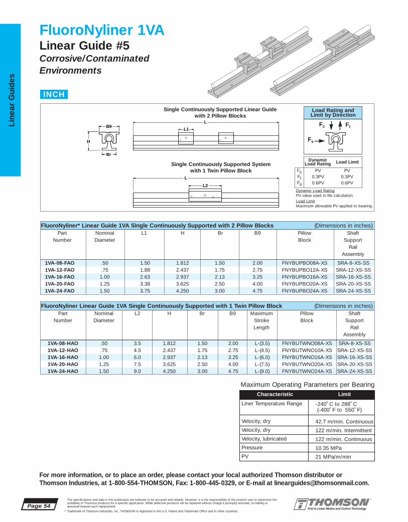
1VA-08-HAO .50 3.5 1.812 1.50 2.00 L-(3.5) FNYBUTWNO08A-XS SRA-8-XS-SS1VA-12-HAO .75 4.5 2.437 1.75 2.75 L-(4.5) FNYBUTWNO10A-XS SRA-12-XS-SS1VA-16-HAO 1.00 6.0 2.937 2.13 3.25 L-(6.0) FNYBUTWNO16A-XS SRA-16-XS-SS1VA-20-HAO 1.25 7.5 3.625 2.50 4.00 L-(7.5) FNYBUTWNO20A-XS SRA-20-XS-SS1VA-24-HAO 1.50 9.0 4.250 3.00 4.75 L-(9.0) FNYBUTWNO24A-XS SRA-24-XS-SS
1VA-08-FAO .50 1.50 1.812 1.50 2.00 FNYBUPBO08A-XS SRA-8-XS-SS1VA-12-FAO .75 1.88 2.437 1.75 2.75 FNYBUPBO12A-XS SRA-12-XS-SS1VA-16-FAO 1.00 2.63 2.937 2.13 3.25 FNYBUPBO16A-XS SRA-16-XS-SS1VA-20-FAO 1.25 3.38 3.625 2.50 4.00 FNYBUPBO20A-XS SRA-20-XS-SS1VA-24-FAO 1.50 3.75 4.250 3.00 4.75 FNYBUPBO24A-XS SRA-24-XS-SS
Page 54The specifications and data in this publication are believed to be accurate and reliable. However, it is the responsibility of the product user to determine thesuitability of Thomson products for a specific application. While defective products will be replaced without charge if promptly returned, no liability is assumed beyond such replacement.
* Trademark of Thomson Industries, Inc. THOMSON is registered in the U.S. Patent and Trademark Office and in other countries.
Line
ar G
uid
es
For more information, or to place an order, please contact your local authorized Thomson distributor orThomson Industries, at 1-800-554-THOMSON, Fax: 1-800-445-0329, or E-mail at [email protected].
FluoroNyliner 1VALinear Guide #5Corrosive/ContaminatedEnvironments
L2
L1 B9
Br
H
L
L
FluoroNyliner* Linear Guide 1VA Single Continuously Supported with 2 Pillow Blocks (Dimensions in inches)Part Nominal L1 H Br B9 Pillow Shaft
Number Diameter Block SupportRail
Assembly
FluoroNyliner Linear Guide 1VA Single Continuously Supported with 1 Twin Pillow Block (Dimensions in inches)Part Nominal L2 H Br B9 Maximum Pillow Shaft
Number Diameter Stroke Block SupportLength Rail
Assembly
Single Continuously Supported Linear Guidewith 2 Pillow Blocks
Single Continuously Supported System with 1 Twin Pillow Block
INCH
Maximum Operating Parameters per BearingCharacteristic Limit
Liner Temperature Range
Velocity, dry
Velocity, dry
Velocity, lubricated
Pressure
PV
-240˚ C to 288˚ C (-400˚ F to 550˚ F)
42.7 m/min. Continuous
122 m/min. Intermittent
122 m/min. Continuous
10.35 MPa
21 MPa/m/min
FcFtFs
PV0.3PV0.6PV
PV0.3PV0.6PV
DynamicLoad Rating Load Limit
Load Rating andLimit by Direction
Fc Ft
Fs
Dynamic Load RatingPV value used in life calculation.Load LimitMaximum allowable PV applied to bearing.
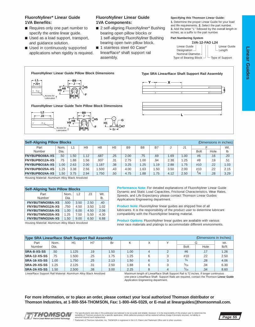
SRA-8-XS-SS .50 1.125 .19 1.50 1.00 4 2 #6 .17 1.26SRA-12-XS-SS .75 1.500 .25 1.75 1.25 6 3 #10 .22 2.50SRA-16-XS-SS 1.00 1.750 .25 2.13 1.50 6 3 1⁄4 .28 4.06SRA-20-XS-SS 1.25 2.125 .31 2.50 1.88 6 3 5⁄16 .34 6.30SRA-24-XS-SS 1.50 2.500 .38 3.00 2.25 8 4 5⁄16 .34 8.60
FNYBUTWNO08A-XS .500 3.50 2.50 .40FNYBUTWNO12A-XS .750 4.50 3.50 1.02FNYBUTWNO16A-XS 1.00 6.00 4.50 2.06FNYBUTWNO20A-XS 1.25 7.50 5.50 4.30FNYBUTWNO24A-XS 1.50 9.00 6.50 6.88
FNYBUPBO08A-XS .50 1.50 1.12 .687 .25 2.00 .75 .69 1.69 1.00 #6 .16 .20FNYBUPBO12A-XS .75 1.88 1.56 .937 .31 2.75 1.00 .94 2.38 1.25 #8 .19 .51FNYBUPBO16A-XS 1.00 2.63 2.00 1.187 .38 3.25 1.25 1.19 2.88 1.75 #10 .22 1.03FNYBUPBO20A-XS 1.25 3.38 2.56 1.500 .43 4.00 1.63 1.50 3.50 2.00 #10 .22 2.15FNYBUPBO24A-XS 1.50 3.75 2.94 1.750 .50 4.75 1.88 1.75 4.12 2.50 1⁄4 .28 3.29
The specifications and data in this publication are believed to be accurate and reliable. However, it is the responsibility of the product user to determine thesuitability of Thomson products for a specific application. While defective products will be replaced without charge if promptly returned, no liability is assumed beyond such replacement.
* Trademark of Thomson Industries, Inc. THOMSON is registered in the U.S. Patent and Trademark Office and in other countries.
Linear Guid
es
Page 55
For more information, or to place an order, please contact your local authorized Thomson distributor orThomson Industries, at 1-800-554-THOMSON, Fax: 1-800-445-0329, or E-mail at [email protected].
B9
J3
H8 H5H9
L1
L2
J1 J
H5
F
Br
H1
B9
H8
H7H9
J
F
G
B8 B6
B8 B6
Access forLubrication †
Access forLubrication ‡
FluoroNyliner* Linear Guide 1VA Benefits:■ Requires only one part number to
specify the entire linear guide.■ Used as a load support, transport,
and guidance solution.■ Used in continuously supported
applications when rigidity is required.
FluoroNyliner Linear Guide 1VA Components:■ 2 self-aligning FluoroNyliner* Bushing
bearing open pillow blocks or 1 self-aligning FluoroNyliner Bushingbearing open twin pillow block.
■ 1 stainless steel 60 Case*linearRace* shaft support rail assembly.
Specifying this Thomson Linear Guide:1. Determine the proper Linear Guide for your loadand life requirements. 2. Select the part number. 3. Add the letter “L” followed by the overall length ininches, as a suffix to the part number.
Part Numbering System
1VA-12-FAO L24Linear Guide Linear GuideDesignation LengthNominal Diameter
Type of Bearing Block Type of Support
Part Nom. L1 H9 H8 H5 B9 B8 B7 J J1 F Wt.Number Dia. Bolt Hole lb
Self-Aligning Pillow Blocks (Dimensions in inches)
Part Nom. H1 H7 Br K X Y G Wt.Number Dia. Bolt Hole lb/ft
Type SRA LinearRace Shaft Support Rail Assembly (Dimensions in Inches)
LL
YY XX
KK
Housing Material: Aluminum Alloy Black Anodized
Housing Material: Aluminum Alloy Black Anodized
LinearRace Support Rail Material: Aluminum Alloy Black Anodized Maximum length of LinearRace Shaft Support Rail is 72 inches. If longer continuous one-piece LinearRace Shaft Support Rails are required, contact the Thomson Linear GuideApplication Engineering department.
FluoroNyliner Linear Guide Pillow Block Dimensions Type SRA LinearRace Shaft Support Rail Assembly
FluoroNyliner Linear Guide Twin Pillow Block Dimensions
Part Nom. L2 J3 Wt.Number Dia. lb.
Self-Aligning Twin Pillow Blocks Performance Note: For detailed explanations of FluoroNyliner Linear GuideDynamic and Static Load Capacities, Frictional Characteristics, Wear Rates,Speeds, and Life Expectancy please contact Thomson Linear GuidesApplications Engineering department.
Product Note: FluoroNyliner linear guides are shipped free of all lubricants. It is the responsibility of the product user to determine lubricantcompatibility with the FluoroNyliner bearing material.
Product Options: FluoroNyliner linear guides are available with variousinner race materials and platings to accommodate different environments.
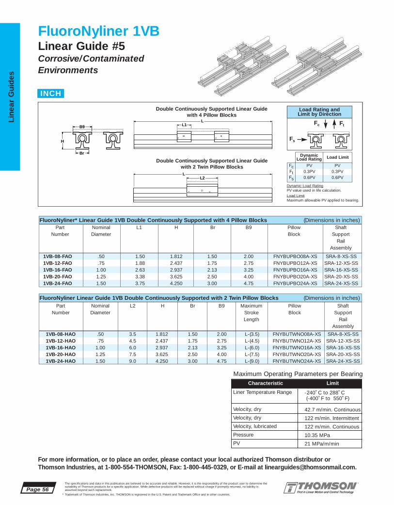
1VB-08-HAO .50 3.5 1.812 1.50 2.00 L-(3.5) FNYBUTWNO08A-XS SRA-8-XS-SS1VB-12-HAO .75 4.5 2.437 1.75 2.75 L-(4.5) FNYBUTWNO12A-XS SRA-12-XS-SS1VB-16-HAO 1.00 6.0 2.937 2.13 3.25 L-(6.0) FNYBUTWNO16A-XS SRA-16-XS-SS1VB-20-HAO 1.25 7.5 3.625 2.50 4.00 L-(7.5) FNYBUTWNO20A-XS SRA-20-XS-SS1VB-24-HAO 1.50 9.0 4.250 3.00 4.75 L-(9.0) FNYBUTWNO24A-XS SRA-24-XS-SS
1VB-08-FAO .50 1.50 1.812 1.50 2.00 FNYBUPBO08A-XS SRA-8-XS-SS1VB-12-FAO .75 1.88 2.437 1.75 2.75 FNYBUPBO12A-XS SRA-12-XS-SS1VB-16-FAO 1.00 2.63 2.937 2.13 3.25 FNYBUPBO16A-XS SRA-16-XS-SS1VB-20-FAO 1.25 3.38 3.625 2.50 4.00 FNYBUPBO20A-XS SRA-20-XS-SS1VB-24-FAO 1.50 3.75 4.250 3.00 4.75 FNYBUPBO24A-XS SRA-24-XS-SS
Page 56The specifications and data in this publication are believed to be accurate and reliable. However, it is the responsibility of the product user to determine thesuitability of Thomson products for a specific application. While defective products will be replaced without charge if promptly returned, no liability is assumed beyond such replacement.
* Trademark of Thomson Industries, Inc. THOMSON is registered in the U.S. Patent and Trademark Office and in other countries.
Line
ar G
uid
es
For more information, or to place an order, please contact your local authorized Thomson distributor orThomson Industries, at 1-800-554-THOMSON, Fax: 1-800-445-0329, or E-mail at [email protected].
FluoroNyliner 1VBLinear Guide #5Corrosive/ContaminatedEnvironments
L2
L1
L
LB9
Br
H
Double Continuously Supported Linear Guide with 4 Pillow Blocks
Double Continuously Supported Linear Guide with 2 Twin Pillow Blocks
FluoroNyliner* Linear Guide 1VB Double Continuously Supported with 4 Pillow Blocks (Dimensions in inches)Part Nominal L1 H Br B9 Pillow Shaft
Number Diameter Block SupportRail
Assembly
FluoroNyliner Linear Guide 1VB Double Continuously Supported with 2 Twin Pillow Blocks (Dimensions in inches)Part Nominal L2 H Br B9 Maximum Pillow Shaft
Number Diameter Stroke Block SupportLength Rail
Assembly
INCH
Maximum Operating Parameters per BearingCharacteristic Limit
Liner Temperature Range
Velocity, dry
Velocity, dry
Velocity, lubricated
Pressure
PV
-240˚ C to 288˚ C (-400˚ F to 550˚ F)
42.7 m/min. Continuous
122 m/min. Intermittent
122 m/min. Continuous
10.35 MPa
21 MPa/m/min
Load Rating andLimit by Direction
Dynamic Load RatingPV value used in life calculation.Load LimitMaximum allowable PV applied to bearing.
Fc Ft
Fs
FcFtFs
PV0.3PV0.6PV
PV0.3PV0.6PV
DynamicLoad Rating Load Limit

SRA-8-XS-SS .50 1.125 .19 1.50 1.00 4 2 #6 .17 1.26SRA-12-XS-SS .75 1.500 .25 1.75 1.25 6 3 #10 .22 2.50SRA-16-XS-SS 1.00 1.750 .25 2.13 1.50 6 3 1⁄4 .28 4.06SRA-20-XS-SS 1.25 2.125 .31 2.50 1.88 6 3 5⁄16 .34 6.30SRA-24-XS-SS 1.50 2.500 .38 3.00 2.25 8 4 5⁄16 .34 8.60
FNYBUTWNO08A-XS .500 3.50 2.50 .40FNYBUTWNO12A-XS .750 4.50 3.50 1.02FNYBUTWNO16A-XS 1.00 6.00 4.50 2.06FNYBUTWNO20A-XS 1.25 7.50 5.50 4.30FNYBUTWNO24A-XS 1.50 9.00 6.50 6.88
FNYBUPBO08A-XS .50 1.50 1.12 .687 .25 2.00 .75 .69 1.69 1.00 #6 .16 .20FNYBUPBO12A-XS .75 1.88 1.56 .937 .31 2.75 1.00 .94 2.38 1.25 #8 .19 .51FNYBUPBO16A-XS 1.00 2.63 2.00 1.187 .38 3.25 1.25 1.19 2.88 1.75 #10 .22 1.03FNYBUPBO20A-XS 1.25 3.38 2.56 1.500 .43 4.00 1.63 1.50 3.50 2.00 #10 .22 2.15FNYBUPBO24A-XS 1.50 3.75 2.94 1.750 .50 4.75 1.88 1.75 4.12 2.50 1⁄4 .28 3.29
The specifications and data in this publication are believed to be accurate and reliable. However, it is the responsibility of the product user to determine thesuitability of Thomson products for a specific application. While defective products will be replaced without charge if promptly returned, no liability is assumed beyond such replacement.
* Trademark of Thomson Industries, Inc. THOMSON is registered in the U.S. Patent and Trademark Office and in other countries.
Linear Guid
es
Page 57
For more information, or to place an order, please contact your local authorized Thomson distributor orThomson Industries, at 1-800-554-THOMSON, Fax: 1-800-445-0329, or E-mail at [email protected].
B9
J3
H8 H5H9
L1
L2
J1 J
H5
F
Br
H1
B9
H8
H7H9
J
F
G
B8 B6
B8 B6
Access forLubrication †
Access forLubrication ‡
FluoroNyliner* Linear Guide 1VB Benefits:■ Requires only one part number to
specify the entire linear guide.■ Allows for custom table mounting.■ Used in continuously supported
applications when rigidity isrequired.
FluoroNyliner Linear Guide 1VB Components:■ 4 self-aligning FluoroNyliner*
Bushing bearing open pillow blocksor 2 self-aligning FluoroNylinerBushing bearing open twin pillowblocks.
■ 2 Stainless Steel 60 Case*LinearRace* Shaft Support RailAssemblies.
Specifying a Thomson Linear Guide:1. Determine the proper system for your load and liferequirements. 2. Select the part number. 3. Add theletter “L” followed by the overall length in inches, asa suffix to the part number.
Part Numbering System
1VB-12-FAO L24Linear guide Linear GuideDesignation LengthNominal Diameter
Type of Bearing Block Type of Support
LL
YY XX
KK
FluoroNyliner Linear Guide Pillow Block Dimensions
Type SRA LinearRace Shaft Support Rail Assembly
FluoroNyliner Linear Guide Twin Pillow Block Dimensions
Part Nom. L1 H9 H8 H5 B9 B8 B7 J J1 F Wt.Number Dia. Bolt Hole lb
Self-Aligning Pillow Blocks (Dimensions in inches)
Part Nom. H1 H7 Br K X Y G Wt.Number Dia. Bolt Hole lb/ft
Type SRA LinearRace Shaft Support Rail Assembly (Dimensions in Inches)
Housing Material: Aluminum Alloy Black Anodized
Housing Material: Aluminum Alloy Black Anodized
LinearRace Support Rail Material: Aluminum Alloy Black Anodized Maximum length of LinearRace shaft support rail is 72 inches. If longer continuous one-piece LinearRaceSupport Rails are required, contact the Thomson Linear Guide Application Engineering department.
Part Nom. L2 J3 Wt.Number Dia. lb.
Self-Aligning Twin Pillow Blocks Performance Note: For detailed explanations of FluoroNyliner Linear GuideDynamic and Static Load Capacities, Frictional Characteristics, Wear Rates,Speeds, and Life Expectancy please contact Thomson Linear GuidesApplications Engineering department.
Product Note: FluoroNyliner linear guides are shipped free of all lubricants.It is the responsibility of the product user to determine lubricant compatibility with the FluoroNyliner bearing material.
Product Options: FluoroNyliner linear guides are available with variousinner race materials and platings to accommodate different environments.
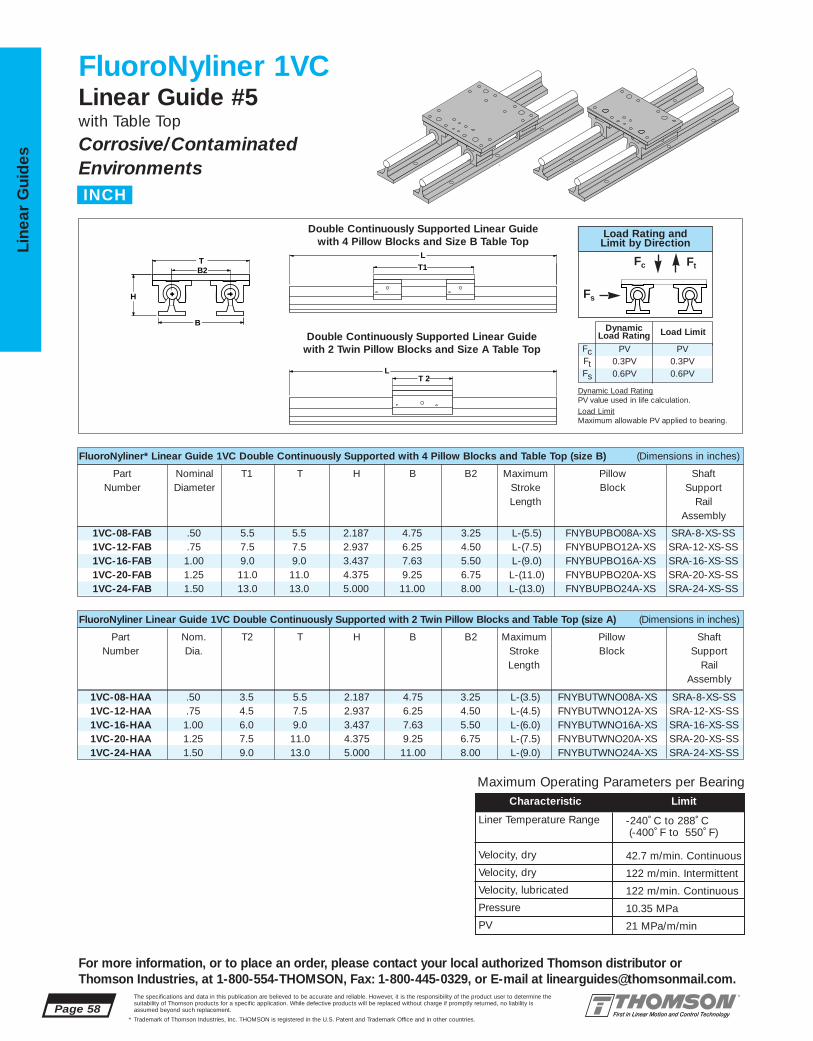
1VC-08-FAB .50 5.5 5.5 2.187 4.75 3.25 L-(5.5) FNYBUPBO08A-XS SRA-8-XS-SS1VC-12-FAB .75 7.5 7.5 2.937 6.25 4.50 L-(7.5) FNYBUPBO12A-XS SRA-12-XS-SS1VC-16-FAB 1.00 9.0 9.0 3.437 7.63 5.50 L-(9.0) FNYBUPBO16A-XS SRA-16-XS-SS1VC-20-FAB 1.25 11.0 11.0 4.375 9.25 6.75 L-(11.0) FNYBUPBO20A-XS SRA-20-XS-SS1VC-24-FAB 1.50 13.0 13.0 5.000 11.00 8.00 L-(13.0) FNYBUPBO24A-XS SRA-24-XS-SS
1VC-08-HAA .50 3.5 5.5 2.187 4.75 3.25 L-(3.5) FNYBUTWNO08A-XS SRA-8-XS-SS1VC-12-HAA .75 4.5 7.5 2.937 6.25 4.50 L-(4.5) FNYBUTWNO12A-XS SRA-12-XS-SS1VC-16-HAA 1.00 6.0 9.0 3.437 7.63 5.50 L-(6.0) FNYBUTWNO16A-XS SRA-16-XS-SS1VC-20-HAA 1.25 7.5 11.0 4.375 9.25 6.75 L-(7.5) FNYBUTWNO20A-XS SRA-20-XS-SS1VC-24-HAA 1.50 9.0 13.0 5.000 11.00 8.00 L-(9.0) FNYBUTWNO24A-XS SRA-24-XS-SS
Page 58The specifications and data in this publication are believed to be accurate and reliable. However, it is the responsibility of the product user to determine thesuitability of Thomson products for a specific application. While defective products will be replaced without charge if promptly returned, no liability is assumed beyond such replacement.
* Trademark of Thomson Industries, Inc. THOMSON is registered in the U.S. Patent and Trademark Office and in other countries.
Line
ar G
uid
es
For more information, or to place an order, please contact your local authorized Thomson distributor orThomson Industries, at 1-800-554-THOMSON, Fax: 1-800-445-0329, or E-mail at [email protected].
FluoroNyliner 1VCLinear Guide #5with Table Top
Corrosive/ContaminatedEnvironments
T 2
T1
L
L
B2 T
B
H
FluoroNyliner* Linear Guide 1VC Double Continuously Supported with 4 Pillow Blocks and Table Top (size B) (Dimensions in inches)
Part Nominal T1 T H B B2 Maximum Pillow ShaftNumber Diameter Stroke Block Support
Length RailAssembly
FluoroNyliner Linear Guide 1VC Double Continuously Supported with 2 Twin Pillow Blocks and Table Top (size A) (Dimensions in inches)
Part Nom. T2 T H B B2 Maximum Pillow ShaftNumber Dia. Stroke Block Support
Length RailAssembly
Double Continuously Supported Linear Guide with 4 Pillow Blocks and Size B Table Top
Double Continuously Supported Linear Guide with 2 Twin Pillow Blocks and Size A Table Top
INCH
Maximum Operating Parameters per BearingCharacteristic Limit
Liner Temperature Range
Velocity, dry
Velocity, dry
Velocity, lubricated
Pressure
PV
-240˚ C to 288˚ C (-400˚ F to 550˚ F)
42.7 m/min. Continuous
122 m/min. Intermittent
122 m/min. Continuous
10.35 MPa
21 MPa/m/min
Load Rating andLimit by Direction
Dynamic Load RatingPV value used in life calculation.Load LimitMaximum allowable PV applied to bearing.
Fc Ft
Fs
FcFtFs
PV0.3PV0.6PV
PV0.3PV0.6PV
DynamicLoad Rating Load Limit

.50 5.5 3.25 1.69 .375 1/4-20 5.5 1.00 .34 .28 4.5 3.5 2.5 .50 .31 2.5
.75 7.5 4.50 2.38 .500 5/16-18 7.5 1.25 .41 .31 6.0 4.5 3.5 .50 .31 3.01.00 9.0 5.50 2.88 .500 3/8-16 9.0 1.75 .53 .31 7.0 6.0 4.5 .75 .31 4.01.25 11.0 6.75 3.50 .750 1/2-13 11.0 2.00 .82 .38 8.5 7.5 5.5 1.00 .38 5.01.50 13.0 8.00 4.12 .750 1/2-13 13.0 2.50 .75 .44 10.0 9.0 6.5 1.25 .44 6.0
SRA- 8-XS-SS .50 1.125 .19 1.50 1.00 4 2 #6 .17 1.26SRA-12-XS-SS .75 1.500 .25 1.75 1.25 6 3 #10 .22 2.50SRA-16-XS-SS 1.00 1.750 .25 2.13 1.50 6 3 1⁄4 .28 4.06SRA-20-XS-SS 1.25 2.125 .31 2.50 1.88 6 3 5⁄16 .34 6.30SRA-24-XS-SS 1.50 2.500 .38 3.00 2.25 8 4 5⁄16 .34 8.60
FNYBUTWNO08A-XS .50 3.5 2.5 .40FNYBUTWNO12A-XS .75 4.5 3.5 1.02FNYBUTWNO16A-XS 1.00 6.0 4.5 2.06FNYBUTWNO20A-XS 1.25 7.5 5.5 4.30FNYBUTWNO24A-XS 1.50 9.0 6.5 6.88
FNYBUPBO08A-XS .50 1.50 1.12 .687 .25 2.00 .75 .69 1.69 1.00 #6 .16 .20FNYBUPBO12A-XS .75 1.88 1.56 .937 .31 2.75 1.00 .94 2.38 1.25 #8 .19 .51FNYBUPBO16A-XS 1.00 2.63 2.00 1.187 .38 3.25 1.25 1.19 2.88 1.75 #10 .22 1.03FNYBUPBO20A-XS 1.25 3.38 2.56 1.500 .43 4.00 1.63 1.50 3.50 2.00 #10 .22 2.15FNYBUPBO24A-XS 1.50 3.75 2.94 1.750 .50 4.75 1.88 1.75 4.12 2.50 1⁄4 .28 3.29
The specifications and data in this publication are believed to be accurate and reliable. However, it is the responsibility of the product user to determine thesuitability of Thomson products for a specific application. While defective products will be replaced without charge if promptly returned, no liability is assumed beyond such replacement.
* Trademark of Thomson Industries, Inc. THOMSON is registered in the U.S. Patent and Trademark Office and in other countries.
Linear Guid
es
Page 59
For more information, or to place an order, please contact your local authorized Thomson distributor orThomson Industries, at 1-800-554-THOMSON, Fax: 1-800-445-0329, or E-mail at [email protected].
Nominal All Table Tops Table Top Size B Table Top Size ADiameter T M J H6 F5 T1 J1 J4 J5 N T2 J3 J4 J5 N1
B9
J3
H8 H5H9
L1
L2
J1 J
H5
F
Br
H1
B9
H8
H7H9
J
F
G
B8 B6
B8 B6
Access forLubrication †
Access forLubrication ‡
FluoroNyliner Linear Guide 1VC Components:■ 4 self-aligning FluoroNyliner polymer
linear guides open type pillow blocks or 2 self-aligning FluoroNyliner open twin pillow blocks.
■ 2 stainless steel 60 Case* LinearRace*Shaft Support Rail Assemblies.
■ 1 mounting table top with work piece andBall Screw Assembly attachment holes.
FluoroNyliner* Linear Guide 1VC Benefits:■ Requires only one part number to specify
the entire linear guide.■ Includes table top with standard tapped
holes for quick and easy mounting of the work piece.
■ Includes Ball Screw Assembly attachmentholes for ease of assembly and actuation.
■ Used in continuously supported applications when rigidity is required.
Mounting Table Top (Dimensions in inches)
Specifying a Thomson Linear Guide:1. Determine the proper system for your load and liferequirements. 2. Select the part number. 3. Add theletter “L” followed by the overall length in inches, as asuffix to the part number.
Part Numbering System
1VC-12-FAB L24Linear Guide Linear GuideDesignation LengthNominal Diameter Type of Table Top
Type of Bearing Block Type of Support
YY XX
LL
KK
J
J5
H6
M
N, N1 T1, T2
J3J1
F5
T
J4
Material: Aluminum Alloy Black Anodized
FluoroNyliner Linear Guide Pillow Block Dimensions
FluoroNyliner Linear Guide Twin Pillow Block Dimensions
Type SRA LinearRace Shaft Support Rail Assembly Mounting Table Top
Part Nom. L1 H9 H8 H5 B9 B8 B6 J J1 F Wt.Number Dia. Bolt Hole lb
Self-Aligning Pillow Blocks (Dimensions in inches)
Part Nom. H1 H7 Br K X Y G Wt.Number Dia. Bolt Hole lb/ft
Type SRA LinearRace Shaft Support Rail Assembly (Dimensions in inches)
Housing Material: Aluminum Alloy Black Anodized
LinearRace Shaft Support Rail Material: Aluminum Alloy Black Anodized
Maximum length of LinearRace Shaft Support Rail is 72 inches. If longer continuous one-piece LinearRaceShaft Support Rails are required, contact the Thomson Linear Guides application engineering department.
Self-Aligning Twin Pillow Blocks
Housing Material: Aluminum Alloy Black Anodized
Part Nom. L2 J3 Wt.Number Dia. lb
Performance Note: For detailed explanations ofFluoroNyliner Linear Guide Dynamic and Static LoadCapacities, Frictional Characteristics, Wear Rates, Speeds,and Life Expectancy please contact Thomson Linear GuidesApplications Engineering department.
Product Note: FluoroNyliner linear guides are shipped free of all lubricants. It is the responsibility of the product user to determinelubricant compatibility with the FluoroNyliner bearing material.
Product Options: FluoroNyliner linear guides are available with various inner race materials and platings to accommodate differentenvironments.

Page 60The specifications and data in this publication are believed to be accurate and reliable. However, it is the responsibility of the product user to determine thesuitability of Thomson products for a specific application. While defective products will be replaced without charge if promptly returned, no liability is assumed beyond such replacement.
* Trademark of Thomson Industries, Inc. THOMSON is registered in the U.S. Patent and Trademark Office and in other countries.
Line
ar G
uid
es
A P P L I C A T I O N W O R K S H E E TP R O J E C T T I T L E :
N O T E S
For more information, or to place an order, please contact your local authorized Thomson distributor orThomson Industries, at 1-800-554-THOMSON, Fax: 1-800-445-0329, or E-mail at [email protected].

Continuous Support Linear Ball Guides #6
The specifications and data in this publication are believed to be accurate and reliable. However, it is the responsibility of the product user to determine thesuitability of Thomson products for a specific application. While defective products will be replaced without charge if promptly returned, no liability is assumed beyond such replacement.
* Trademark of Thomson Industries, Inc. THOMSON is registered in the U.S. Patent and Trademark Office and in other countries.
Linear Guid
es
Page 61
For more information, or to place an order, please contact your local authorized Thomson distributor orThomson Industries, at 1-800-554-THOMSON, Fax: 1-800-445-0329, or E-mail at [email protected].
3
2
1 4NEW
5NEW
6
7 9 1112
13
1415
16
8NEW 10
NEW17NEW
Continuous Support Linear Ball Guides Offer:
HIGH SPEED, SMOOTH OPERATION, EASY TO INSTALL
■ Increased life within the same envelope.RoundRail* linear guides feature the new patented Super Smart Ball Bushing* bearingsfor up to 216X the life or 6X the load capacityof conventional bearings
■ Cost savings: save time and money preparingyour mounting surfaces before bolting downRoundRail linear guides
■ Superior performance. Continuously supportedfor maximum (down- & side-) load applications without concerns for shaft deflection
■ The RoundRail Advantage*. The inherent self-aligning-in-all-directions design of theSuper Smart Ball Bushing bearing allows forultra smooth travel when mounted to wider toleranced prepared surfaces
■ Unlimited travel lengths without concerns for machined reference edges or butt jointalignment
■ The Super Smart Ball Bushing bearing…themost technologically advanced and mostrobust linear bearing in the world
■ Corrosion resistant versions for maximum performance in harsh environments.
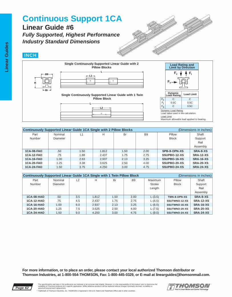
FcFtFs
C0.5C
C
C0.5C0.5C
DynamicLoad Rating Load Limit
1CA-08-FAO .50 1.50 1.812 1.50 2.00 SPB-8-OPN-XS SRA-8-XS1CA-12-FAO .75 1.88 2.437 1.75 2.75 SSUPBO-12-XS SRA-12-XS1CA-16-FAO 1.00 2.63 2.937 2.13 3.25 SSUPBO-16-XS SRA-16-XS1CA-20-FAO 1.25 3.38 3.625 2.50 4.00 SSUPBO-20-XS SRA-20-XS1CA-24-FAO 1.50 3.75 4.250 3.00 4.75 SSUPBO-24-XS SRA-24-XS
Load Rating andLimit by Direction
1CA-08-HAO .50 3.5 1.812 1.50 2.00 L-(3.5) TWN-8-OPN-XS SRA-8-XS1CA-12-HAO .75 4.5 2.437 1.75 2.75 L-(4.5) SSUTWNO-12-XS SRA-12-XS1CA-16-HAO 1.00 6.0 2.937 2.13 3.25 L-(6.0) SSUTWNO-16-XS SRA-16-XS1CA-20-HAO 1.25 7.5 3.625 2.50 4.00 L-(7.5) SSUTWNO-20-XS SRA-20-XS1CA-24-HAO 1.50 9.0 4.250 3.00 4.75 L-(9.0) SSUTWNO-24-XS SRA-24-XS
Page 62The specifications and data in this publication are believed to be accurate and reliable. However, it is the responsibility of the product user to determine thesuitability of Thomson products for a specific application. While defective products will be replaced without charge if promptly returned, no liability is assumed beyond such replacement.
* Trademark of Thomson Industries, Inc. THOMSON is registered in the U.S. Patent and Trademark Office and in other countries.
Line
ar G
uid
es
For more information, or to place an order, please contact your local authorized Thomson distributor orThomson Industries, at 1-800-554-THOMSON, Fax: 1-800-445-0329, or E-mail at [email protected].
Continuous Support 1CALinear Guide #6Fully Supported, Highest PerformanceIndustry Standard Dimensions
L2
L1 B9
Br
H
L
L
Continuously Supported Linear Guide 1CA Single with 2 Pillow Blocks (Dimensions in inches)Part Nominal L1 H Br B9 Pillow Shaft
Number Diameter Block SupportRail
Assembly
Continuously Supported Linear Guide 1CA Single with 1 Twin Pillow Block (Dimensions in inches)Part Nominal L2 H Br B9 Maximum Pillow Shaft
Number Diameter Stroke Block SupportLength Rail
Assembly
Single Continuously Supported Linear Guide with 2Pillow Blocks
Single Continuously Supported Linear Guide with 1 TwinPillow Block
INCH
Fc Ft
Fs
Dynamic Load RatingLoad value used in life calculation.Load LimitMaximum allowable load applied to bearing.

TWN-8-OPN-XS
SSUTWNO-16-XS
SSUTWNO-24-XS
SPB-8-OPN-XS .50 1.50 1.12 .687 .25 2.00 .75 .69 1.69 1.00 #6 .16 .20SSUPBO-12-XS .75 1.88 1.56 .937 .31 2.75 1.00 .94 2.38 1.25 #8 .19 .51SSUPBO-16-XS 1.00 2.63 2.00 1.187 .38 3.25 1.25 1.19 2.88 1.75 #10 .22 1.03SSUPBO-20-XS 1.25 3.38 2.56 1.500 .43 4.00 1.63 1.50 3.50 2.00 #10 .22 2.15SSUPBO-24-XS 1.50 3.75 2.94 1.750 .50 4.75 1.88 1.75 4.12 2.50 1⁄4 .28 3.29
1CA-08-FAO 290 SPB-8-OPN-XS 1451CA-12-FAO 1800 SSUPBO-12-XS 9001CA-16-FAO 3000 SSUPBO-16-XS 15001CA-20-FAO 3730 SSUPBO-20-XS 18651CA-24-FAO 6160 SSUPBO-24-XS 3080
1CA-08-HAO 290 TWN-8-OPN-XS 2901CA-12-HAO 1800 SSUTWNO-12-XS 18001CA-16-HAO 3000 SSUTWNO-16-XS 30001CA-20-HAO 3730 SSUTWNO-20-XS 37301CA-24-HAO 6160 SSUTWNO-24-XS 6160
SRA-8-XS .50 1.125 .19 1.50 1.00 4 2 #6 .17 1.26SRA-12-XS .75 1.500 .25 1.75 1.25 6 3 #10 .22 2.50SRA-16-XS 1.00 1.750 .25 2.13 1.50 6 3 1⁄4 .28 4.06SRA-20-XS 1.25 2.125 .31 2.50 1.88 6 3 5⁄16 .34 6.30SRA-24-XS 1.50 2.500 .38 3.00 2.25 8 4 5⁄16 .34 8.60
The specifications and data in this publication are believed to be accurate and reliable. However, it is the responsibility of the product user to determine thesuitability of Thomson products for a specific application. While defective products will be replaced without charge if promptly returned, no liability is assumed beyond such replacement.
* Trademark of Thomson Industries, Inc. THOMSON is registered in the U.S. Patent and Trademark Office and in other countries.
Linear Guid
es
Page 63
For more information, or to place an order, please contact your local authorized Thomson distributor orThomson Industries, at 1-800-554-THOMSON, Fax: 1-800-445-0329, or E-mail at [email protected].
B9
J3
H8 H5H9
L1
L2
J1 J
H5
F
Br
H1
B9
H8
H7H9
J
F
G
B8 B6
B8 B6
Access forLubrication †
Access forLubrication ‡
Continuously Supported Linear Guide 1CA Benefits:■ Requires only one part number to
specify the entire linear guide.■ Used as a load support, transport,
and guidance solution.■ Used in continuously supported
applications when rigidity is required.
Continuously Supported Linear Guides 1CA Components:†
■ 2 Super Smart Ball Bushing* opentype pillow blocks or 1 Super Smart Ball Bushing open twin pillow blocks.
■ 1 60 Case* LinearRace* shaftSupport Rail Assembly.
Specifying this Thomson Linear Guide:1. Determine the proper Linear Guide for your loadand life requirements. 2. Select the part number. 3. Add the letter “L” followed by the overall length ininches, as a suffix to the part number.
Part Numbering System
1CA-12-FAO L24Linear Guide Linear GuideDesignation LengthNominal Diameter
Type of Bearing Block Type of Support
.50 3.5 2.5 .40SSUTWNO-12-XS .75 4.5 3.5 1.02
1.00 6.0 4.5 2.06SSUTWNO-20-XS 1.25 7.5 5.5 4.30
1.50 9.0 6.5 6.88
Part Nom. L1 H9 H8 H5 B9 B8 B6 J J1 F Wt.Number Dia. Bolt Hole lb
Type TWN-OPN and SSUTWNO Pillow BlocksType SPB-OPN and SSUPBO Pillow Blocks (Dimensions in Inches)
Part Nom. H1 H7 Br K X Y G Wt.Number Dia. Bolt Hole lb/ft
Type SRA LinearRace Shaft Support Rail Assembly (Dimensions in Inches)
LL
YY XX
KK
Housing Material: Aluminum Alloy Black Anodized Housing Material: Aluminum Alloy BlackAnodized
LinearRace Shaft Support Rail Material: Aluminum Alloy Black Anodized
Maximum length of LinearRace Shaft Support Rail is 72 inches. If longer continuous one-piece LinearRaceShaft Support Rails are required, contact the Thomson Linear Guides Application Engineering department.
Type SSUPBO Open Type Super Smart Ball Bushing Pillow BlockType SPB-OPN Open Type Ball Bushing Pillow Block
Type SRA LinearRace Shaft Support Rail Assembly
Type SSUTWN Open Type Super Smart Ball Bushing Twin Pillow BlockType TWN-OPN Open Type Ball Bushing Twin Pillow Block
Part Nom. L2 J3 Wt.Number Dia. lb
‡ Size .500 inch has oil lubricant fitting. Sizes .625 and above have 1⁄4-28 access for lubrication.
Dynamic Load Rating (C) Matrix (4 million inches travel)Linear Guide Dynamic Load Pillow Block Pillow Block
Assembly Rating, C (lbf) Part No. Dynamic Load Part No. (Even Distribution) Rating, C (lbf)
Dynamic Load Rating (C) Matrix (4 million inches travel)Linear Guide Dynamic Load Pillow Block Pillow Block
Assembly Rating, C (lbf) Part No. Dynamic Load Part No. (Even Distribution) Rating, C (lbf)
† Super Ball Bushing* bearings are used in .500 inch size pillow blocks.
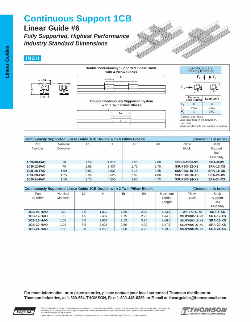
1CB-08-HAO .50 3.5 1.812 1.50 2.00 L-(3.5) TWN-8-OPN-XS SRA-8-XS1CB-12-HAO .75 4.5 2.437 1.75 2.75 L-(4.5) SSUTWNO-12-XS SRA-12-XS1CB-16-HAO 1.00 6.0 2.937 2.13 3.25 L-(6.0) SSUTWNO-16-XS SRA-16-XS1CB-20-HAO 1.25 7.5 3.625 2.50 4.00 L-(7.5) SSUTWNO-20-XS SRA-20-XS1CB-24-HAO 1.50 9.0 4.250 3.00 4.75 L-(9.0) SSUTWNO-24-XS SRA-24-XS
1CB-08-FAO .50 1.50 1.812 1.50 2.00 SPB-8-OPN-XS SRA-8-XS1CB-12-FAO .75 1.88 2.437 1.75 2.75 SSUPBO-12-XS SRA-12-XS1CB-16-FAO 1.00 2.63 2.937 2.13 3.25 SSUPBO-16-XS SRA-16-XS1CB-20-FAO 1.25 3.38 3.625 2.50 4.00 SSUPBO-20-XS SRA-20-XS1CB-24-FAO 1.50 3.75 4.250 3.00 4.75 SSUPBO-24-XS SRA-24-XS
Page 64The specifications and data in this publication are believed to be accurate and reliable. However, it is the responsibility of the product user to determine thesuitability of Thomson products for a specific application. While defective products will be replaced without charge if promptly returned, no liability is assumed beyond such replacement.
* Trademark of Thomson Industries, Inc. THOMSON is registered in the U.S. Patent and Trademark Office and in other countries.
Line
ar G
uid
es
For more information, or to place an order, please contact your local authorized Thomson distributor orThomson Industries, at 1-800-554-THOMSON, Fax: 1-800-445-0329, or E-mail at [email protected].
Continuous Support 1CBLinear Guide #6Fully Supported, Highest PerformanceIndustry Standard Dimensions
Double Continuously Supported Linear Guide with 4 Pillow Blocks
Double Continuously Supported System with 2 Twin Pillow Blocks
Continuously Supported Linear Guide 1CB Double with 4 Pillow Blocks (Dimensions in inches)Part Nominal L1 H Br B9 Pillow Shaft
Number Diameter Block SupportRail
Assembly
Continuously Supported Linear Guide 1CB Double with 2 Twin Pillow Blocks (Dimensions in inches)Part Nominal L2 H Br B9 Maximum Pillow Shaft
Number Diameter Stroke Block SupportLength Rail
Assembly
INCH
L2
L1
L
LB9
Br
H
Load Rating andLimit by Direction
Dynamic Load RatingLoad value used in life calculation.Load LimitMaximum allowable load applied to bearing.
Fc Ft
Fs
FcFtFs
C0.5C
C
C0.5C0.5C
DynamicLoad Rating Load Limit

1.02
4.30
.40
2.06
1.50 9.0 6.5 6.88
SSUPBO-16-XS 1.00 2.63 2.00 1.187 .38 3.25 1.25 1.19 2.88 1.75 #10 .22 1.03
SSUPBO-24-XS 1.50 3.75 2.94 1.750 .50 4.75 1.88 1.75 4.12 2.50 1⁄4 .28 3.29
SSUTWNO-16-XS
SSUTWNO-24-XS
TWN-8-OPN-XSSPB-8-OPN-XS .50 1.50 1.12 .687 .25 2.00 .75 .69 1.69 1.00 #6 .16 .20
1CB-08-FAO 580 SPB-8-OPN-XS 1451CB-12-FAO 3600 SSUPBO-12-XS 9001CB-16-FAO 6000 SSUPBO-16-XS 15001CB-20-FAO 7460 SSUPBO-20-XS 18651CB-24-FAO 12320 SSUPBO-24-XS 3080
1CB-08-HAO 580 TWN-8-OPN-XS 2901CB-12-HAO 3600 SSUTWNO-12-XS 18001CB-16-HAO 6040 SSUTWNO-16-XS 30201CB-20-HAO 7460 SSUTWNO-20-XS 37301CB-24-HAO 12320 SSUTWNO-24-XS 6160
SRA-8-XS .50 1.125 .19 1.50 1.00 4 2 #6 .17 1.26SRA-12-XS .75 1.500 .25 1.75 1.25 6 3 #10 .22 2.50SRA-16-XS 1.00 1.750 .25 2.13 1.50 6 3 1⁄4 .28 4.06SRA-20-XS 1.25 2.125 .31 2.50 1.88 6 3 5⁄16 .34 6.30SRA-24-XS 1.50 2.500 .38 3.00 2.25 8 4 5⁄16 .34 8.60
The specifications and data in this publication are believed to be accurate and reliable. However, it is the responsibility of the product user to determine thesuitability of Thomson products for a specific application. While defective products will be replaced without charge if promptly returned, no liability is assumed beyond such replacement.
* Trademark of Thomson Industries, Inc. THOMSON is registered in the U.S. Patent and Trademark Office and in other countries.
Linear Guid
es
Page 65
For more information, or to place an order, please contact your local authorized Thomson distributor orThomson Industries, at 1-800-554-THOMSON, Fax: 1-800-445-0329, or E-mail at [email protected].
B9
J3
H8 H5H9
L1
L2
J1 J
H5
F
Br
H1
B9
H8
H7H9
J
F
G
B8 B6
B8 B6
Access forLubrication †
Access forLubrication ‡
Continuously Supported Linear Guide 1CB Benefits:■ Requires only one part number to
specify the entire linear guide.■ Allows for custom table mounting.■ Used in continuously supported
applications when rigidity isrequired.
Continuously Supported Linear Guide 1CB Components: †
■ 4 Super Smart Ball Bushing* opentype pillow blocks or 2 Super Smart Ball Bushing open type twinpillow blocks.
■ 2 60 Case* LinearRace* shaftSupport Rail Assemblies.
Specifying a Thomson Linear Guide:1. Determine the proper system for your load and liferequirements. 2. Select the part number. 3. Add theletter “L” followed by the overall length in inches, asa suffix to the part number.
Part Numbering System
1CB-12-FAO L24Linear Guide Linear GuideDesignation LengthNominal Diameter
Type of Bearing Block Type of Support
LL
YY XX
KK
Type SSUPBO Open Type Super Smart Ball Bushing Pillow BlockType SPB-OPN Open Type Ball Bushing Pillow Block
Type SRA LinearRace Shaft Support Rail Assembly
Type SSUTWN Open Type Super Smart Ball Bushing Twin Pillow BlockType TWN-OPN Open Type Ball Bushing Twin Pillow Block
.50 3.5 2.5SSUTWNO-12-XS .75 4.5 3.5
1.00 6.0 4.5SSUTWNO-20-XS 1.25 7.5 5.5
Part Nom. L1 H9 H8 H5 B9 B8 B6 J J1 F Wt.Number Dia. Bolt Hole lb
Type TWN-OPN and SSUTWNO Pillow Blocks
SSUPBO-12-XS .75 1.88 1.56 .937 .31 2.75 1.00 .94 2.38 1.25 #8 .19 .51
SSUPBO-20-XS 1.25 3.38 2.56 1.500 .43 4.00 1.63 1.50 3.50 2.00 #10 .22 2.15
Type SPB-OPN and SSUPBO Pillow Blocks (Dimensions in Inches)
Part Nom. H1 H7 Br K X Y G Wt.Number Dia. Bolt Hole lb/ft
Type SRA LinearRace Shaft Support Rail Assembly (Dimensions in Inches)
Housing Material: Aluminum Alloy Black Anodized Housing Material: Aluminum Alloy BlackAnodized
LinearRace Shaft Support Rail Material: Aluminum Alloy Black Anodized
Maximum length of LinearRace Shaft Support Rail is 72 inches. If longer continuous one-piece LinearRaceShaft Support Rails are required, contact the Thomson Linear Guide Application Engineering department.
Part Nom. L2 J3 Wt.Number Dia. lb
‡ Size .500 inch has oil lubricant fitting. Sizes .625 and above have 1⁄4-28 access for lubrication.
Dynamic Load Rating (C) Matrix (4 million inches travel)Linear Guide Dynamic Load Pillow Block Pillow Block
Assembly Rating, C (lbf) Part No. Dynamic Load Part No. (Even Distribution) Rating, C (lbf)
Dynamic Load Rating (C) Matrix (4 million inches travel)Linear Guide Dynamic Load Pillow Block Pillow Block
Assembly Rating, C (lbf) Part No. Dynamic Load Part No. (Even Distribution) Rating, C (lbf)
† Super Ball Bushing* bearings are used in .500 inch size pillow blocks.
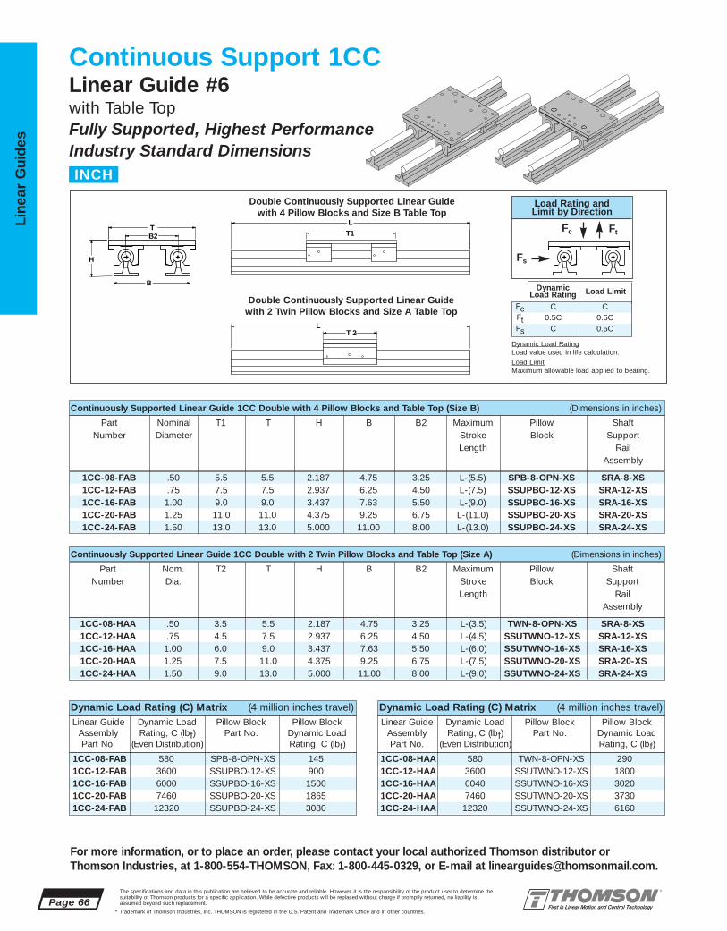
1CC-08-FAB 580 SPB-8-OPN-XS 1451CC-12-FAB 3600 SSUPBO-12-XS 9001CC-16-FAB 6000 SSUPBO-16-XS 15001CC-20-FAB 7460 SSUPBO-20-XS 18651CC-24-FAB 12320 SSUPBO-24-XS 3080
1CC-08-HAA 580 TWN-8-OPN-XS 2901CC-12-HAA 3600 SSUTWNO-12-XS 18001CC-16-HAA 6040 SSUTWNO-16-XS 30201CC-20-HAA 7460 SSUTWNO-20-XS 37301CC-24-HAA 12320 SSUTWNO-24-XS 6160
1CC-08-HAA .50 3.5 5.5 2.187 4.75 3.25 L-(3.5) TWN-8-OPN-XS SRA-8-XS1CC-12-HAA .75 4.5 7.5 2.937 6.25 4.50 L-(4.5) SSUTWNO-12-XS SRA-12-XS1CC-16-HAA 1.00 6.0 9.0 3.437 7.63 5.50 L-(6.0) SSUTWNO-16-XS SRA-16-XS1CC-20-HAA 1.25 7.5 11.0 4.375 9.25 6.75 L-(7.5) SSUTWNO-20-XS SRA-20-XS1CC-24-HAA 1.50 9.0 13.0 5.000 11.00 8.00 L-(9.0) SSUTWNO-24-XS SRA-24-XS
1CC-08-FAB .50 5.5 5.5 2.187 4.75 3.25 L-(5.5) SPB-8-OPN-XS SRA-8-XS1CC-12-FAB .75 7.5 7.5 2.937 6.25 4.50 L-(7.5) SSUPBO-12-XS SRA-12-XS1CC-16-FAB 1.00 9.0 9.0 3.437 7.63 5.50 L-(9.0) SSUPBO-16-XS SRA-16-XS1CC-20-FAB 1.25 11.0 11.0 4.375 9.25 6.75 L-(11.0) SSUPBO-20-XS SRA-20-XS1CC-24-FAB 1.50 13.0 13.0 5.000 11.00 8.00 L-(13.0) SSUPBO-24-XS SRA-24-XS
Page 66The specifications and data in this publication are believed to be accurate and reliable. However, it is the responsibility of the product user to determine thesuitability of Thomson products for a specific application. While defective products will be replaced without charge if promptly returned, no liability is assumed beyond such replacement.
* Trademark of Thomson Industries, Inc. THOMSON is registered in the U.S. Patent and Trademark Office and in other countries.
Line
ar G
uid
es
For more information, or to place an order, please contact your local authorized Thomson distributor orThomson Industries, at 1-800-554-THOMSON, Fax: 1-800-445-0329, or E-mail at [email protected].
Continuous Support 1CCLinear Guide #6with Table TopFully Supported, Highest PerformanceIndustry Standard Dimensions
T 2
T1
L
L
B2 T
B
H
Continuously Supported Linear Guide 1CC Double with 4 Pillow Blocks and Table Top (Size B) (Dimensions in inches)
Part Nominal T1 T H B B2 Maximum Pillow ShaftNumber Diameter Stroke Block Support
Length RailAssembly
Continuously Supported Linear Guide 1CC Double with 2 Twin Pillow Blocks and Table Top (Size A) (Dimensions in inches)
Part Nom. T2 T H B B2 Maximum Pillow ShaftNumber Dia. Stroke Block Support
Length RailAssembly
Double Continuously Supported Linear Guide with 4 Pillow Blocks and Size B Table Top
Double Continuously Supported Linear Guide with 2 Twin Pillow Blocks and Size A Table Top
INCH
Dynamic Load Rating (C) Matrix (4 million inches travel)Linear Guide Dynamic Load Pillow Block Pillow Block
Assembly Rating, C (lbf) Part No. Dynamic Load Part No. (Even Distribution) Rating, C (lbf)
Dynamic Load Rating (C) Matrix (4 million inches travel)Linear Guide Dynamic Load Pillow Block Pillow Block
Assembly Rating, C (lbf) Part No. Dynamic Load Part No. (Even Distribution) Rating, C (lbf)
Load Rating andLimit by Direction
Dynamic Load RatingLoad value used in life calculation.Load LimitMaximum allowable load applied to bearing.
Fc Ft
Fs
FcFtFs
C0.5C
C
C0.5C0.5C
DynamicLoad Rating Load Limit

TWN-8-OPN-XS
SSUTWNO-16-XS
SSUTWNO-24-XS
SPB-8-OPN-XS .50 1.50 1.12 .687 .25 2.00 .75 .69 1.69 1.00 #6 .16 .20
SSUPBO-16-XS 1.00 2.63 2.00 1.187 .38 3.25 1.25 1.19 2.88 1.75 #10 .22 1.03
SSUPBO-24-XS 1.50 3.75 2.94 1.750 .50 4.75 1.88 1.75 4.12 2.50 1⁄4 .28 3.29
.50 5.5 3.25 1.69 .375 1/4-20 5.5 1.00 .34 .28 4.5 3.5 2.5 .50 .31 2.5
.75 7.5 4.50 2.38 .500 5/16-18 7.5 1.25 .41 .31 6.0 4.5 3.5 .50 .31 3.01.00 9.0 5.50 2.88 .500 3/8-16 9.0 1.75 .53 .31 7.0 6.0 4.5 .75 .31 4.01.25 11.0 6.75 3.50 .750 1/2-13 11.0 2.00 .82 .38 8.5 7.5 5.5 1.00 .38 5.01.50 13.0 8.00 4.12 .750 1/2-13 13.0 2.50 .75 .44 10.0 9.0 6.5 1.25 .44 6.0
SRA-8-XS .50 1.125 .19 1.50 1.00 4 2 #6 .17 1.26SRA-12-XS .75 1.500 .25 1.75 1.25 6 3 #10 .22 2.50SRA-16-XS 1.00 1.750 .25 2.13 1.50 6 3 1⁄4 .28 4.06SRA-20-XS 1.25 2.125 .31 2.50 1.88 6 3 5⁄16 .34 6.30SRA-24-XS 1.50 2.500 .38 3.00 2.25 8 4 5⁄16 .34 8.60
The specifications and data in this publication are believed to be accurate and reliable. However, it is the responsibility of the product user to determine thesuitability of Thomson products for a specific application. While defective products will be replaced without charge if promptly returned, no liability is assumed beyond such replacement.
* Trademark of Thomson Industries, Inc. THOMSON is registered in the U.S. Patent and Trademark Office and in other countries.
Linear Guid
es
Page 67
For more information, or to place an order, please contact your local authorized Thomson distributor orThomson Industries, at 1-800-554-THOMSON, Fax: 1-800-445-0329, or E-mail at [email protected].
B9
J3
H8 H5H9
L1
L2
J1 J
H5
F
Br
H1
B9
H8
H7H9
J
F
G
B8 B6
B8 B6
Access forLubrication †
Access forLubrication ‡
Continuously Supported Linear Guide 1CC Benefits:■ Requires only one part number to
specify the entire linear guide.■ Includes table top with standard tapped
holes for quick and easy mounting of the work piece.
■ Includes Ball Screw Assembly attachmentholes for ease of assembly and actuation
■ Used in continuously supported applications when rigidity is required.
Continuously Supported Linear Guide 1CC Components:†
■ 4 Super Smart Ball Bushing* open type pillow blocks or 2 Super Smart BallBushing open type twin pillow blocks.
■ 2 60 Case* LinearRace* shaft Support RailAssemblies.
■ 1 mounting table top with work piece and Ball Screw Assembly attachment holes.
Mounting Table Top (Dimensions in inches)
Specifying a Thomson Linear Guide:1. Determine the proper system for your load and liferequirements. 2. Select the part number. 3. Add theletter “L” followed by the overall length in inches, asa suffix to the part number.
Part Numbering System
1CC-12-FAB L24Linear Guide Linear GuideDesignation LengthNominal Diameter Type of Table Top
Type of Bearing Block Type of Support
YY XX
LL
KK
J
J5
H6
M
N, N1 T1, T2
J3J1
F5
T
J4
Material: Aluminum Alloy Black Anodized
Type SSUPBO Open Type Super Smart Ball Bushing Pillow BlockType SPB Open Type Ball Bushing Pillow Block
Type SSUTWNO Open Type Super Smart Ball Bushing Twin Pillow BlockType TWN-OPN Open Type Ball Bushing Twin Pillow Block
Type SRA LinearRace Shaft Support Rail Assembly Mounting Table Top
.50 3.5 2.5 .40SSUTWNO-12-XS .75 4.5 3.5 1.02
1.00 6.0 4.5 2.06SSUTWNO-20-XS 1.25 7.5 5.5 4.30
1.50 9.0 6.5 6.88
Part Nom. L1 H9 H8 H5 B9 B8 B6 J J1 F Wt.Number Dia. Bolt Hole lb
Type TWN-OPN and SSUTWNO Pillow Blocks
SSUPBO-12-XS .75 1.88 1.56 .937 .31 2.75 1.00 .94 2.38 1.25 #8 .19 .51
SSUPBO-20-XS 1.25 3.38 2.56 1.500 .43 4.00 1.63 1.50 3.50 2.00 #10 .22 2.15
Type SPB-OPN and SSUPBO Pillow Blocks (Dimensions in Inches)
Part Nom. H1 H7 Br K X Y G Wt.Number Dia. Bolt Hole lb/ft
Type SRA LinearRace Shaft Support Rail Assembly (Dimensions in Inches)
Housing Material: Aluminum Alloy Black Anodized Housing Material: Aluminum Alloy BlackAnodized
LinearRace Shaft Support Rail Material: Aluminum Alloy Black Anodized
Maximum length of LinearRace Shaft Support Rail is 72 inches. If longer continuous one-piece LinearRaceShaft Support Rails are required, contact the Thomson Linear Guide Application Engineering department.
Part Nom. L2 J3 Wt.Number Dia. lb
‡ Size .500 inch has oil lubricant fitting.Sizes .625 and above have 1⁄4-28access for lubrication.
Nominal All Table Tops Table Top Size B Table Top Size ADiameter T M J H6 F5 T1 J1 J4 J5 N T2 J3 J4 J5 N1
† Super Ball Bushing* bearings are used in .500 inch size pillow blocks.

1PA-M12-MWO 12 76 46 28 43 21,5 21,5 43 L-(76) SPTWNO-M12-XS SRA-M12-XS1PA-M16-MWO 16 84 52 30 48 24,0 26,5 53 L-(84) SSETWNO-M16-XS SRA-M16-XS1PA-M20-MWO 20 104 63 38 56 28,0 30,0 60 L-(104) SSETWNO-M20-XS SRA-M20-XS1PA-M25-MWO 25 130 72 42 60 30,0 39,0 78 L-(130) SSETWNO-M25-XS SRA-M25-XS1PA-M30-MWO 30 152 88 53 74 37,0 43,5 87 L-(152) SSETWNO-M30-XS SRA-M30-XS1PA-M40-MWO 40 176 105 60 78 39,0 54,0 108 L-(176) SSETWNO-M40-XS SRA-M40-XS
Continuously Supported Linear Guide 1PA Single with 1 Twin Pillow Block (Dimensions in mm)Part Nominal L2 H H1 A A1 B1 B9 Maximum Pillow Shaft
Number Diameter Stroke Block SupportLength Rail
Assembly
1PA-M12-LWO 12 39 46 28 43 21,5 21,5 43 SPPBO-M12-XS SRA-M12-XS1PA-M16-LWO 16 43 52 30 48 24,0 26,5 53 SSEPBO-M16-XS SRA-M16-XS1PA-M20-LWO 20 54 63 38 56 28,0 30,0 60 SSEPBO-M20-XS SRA-M20-XS1PA-M25-LWO 25 67 72 42 60 30,0 39,0 78 SSEPBO-M25-XS SRA-M25-XS1PA-M30-LWO 30 79 88 53 74 37,0 43,5 87 SSEPBO-M30-XS SRA-M30-XS1PA-M40-LWO 40 91 105 60 78 39,0 54,0 108 SSEPBO-M40-XS SRA-M40-XS
Page 68The specifications and data in this publication are believed to be accurate and reliable. However, it is the responsibility of the product user to determine thesuitability of Thomson products for a specific application. While defective products will be replaced without charge if promptly returned, no liability is assumed beyond such replacement.
* Trademark of Thomson Industries, Inc. THOMSON is registered in the U.S. Patent and Trademark Office and in other countries.
Line
ar G
uid
es
For more information, or to place an order, please contact your local authorized Thomson distributor orThomson Industries, at 1-800-554-THOMSON, Fax: 1-800-445-0329, or E-mail at [email protected].
Continuous Support 1PALinear Guide #6Fully Supported, Highest PerformanceIndustry Standard Dimensions
L2
L1 B9 B1
A A1
H H1
L
Single Continuously Supported Linear Guide with 2 Pillow Blocks
Single Continuously Supported Linear Guide with 1 Twin Pillow Block
Continuously Supported Linear Guide 1PA Single with 2 Pillow Blocks (Dimensions in mm)Part Nominal L1 H H1 A A1 B1 B9 Pillow Block Shaft
Number Diameter SupportRail
Assembly
METRIC
Load Rating andLimit by Direction
Dynamic Load RatingLoad value used in life calculation.Load LimitMaximum allowable load applied to bearing.
Fc Ft
Fs
FcFtFs
C0.5C
C
C0.5C0.5C
DynamicLoad Rating Load Limit

1PA-M12-LWO 1500 SPPBO-M12-XS 750
1PA-M16-LWO 4400 SSEPBO-M16-XS 2200
1PA-M20-LWO 8000 SSEPBO-M20-XS 4000
1PA-M25-LWO 13400 SSEPBO-M25-XS 6700
1PA-M30-LWO 16600 SSEPBO-M30-XS 8300
1PA-M40-LWO 27400 SSEPBO-M40-XS 13700
1PA-M12-MWO 1220 SPTWNO-M12-XS 1500
1PA-M16-MWO 4400 SSETWNO-M16-XS 4400
1PA-M20-MWO 8000 SSETWNO-M20-XS 8000
1PA-M25-MWO 13400 SSETWNO-M25-XS 13400
1PA-M30-MWO 16600 SSETWNO-M30-XS 16600
1PA-M40-MWO 27400 SSETWNO-M40-XS 27400
SRA-M12-XS 12 28 5 43 21,5 29 75 37,5 4,5 4,1
SRA-M16-XS 16 30 5 48 24,0 33 100 50 5,5 6,2
SRA-M20-XS 20 38 6 56 28,0 37 100 50 6,6 9,5
SRA-M25-XS 25 42 6 60 30,0 42 120 60 6,6 13,7
SRA-M30-XS 30 53 8 74 37,0 51 150 75 8,6 20,0
SRA-M40-XS 40 60 8 78 39,0 55 200 100 8,6 32,5
SPTWNO-M12-XS 12 76 56 19,5 28 0,22
SSETWNO-M16-XS 16 84 64 21,5 32 0,34
SSETWNO-M20-XS 20 104 76 27,0 38 0,63
SSETWNO-M25-XS 25 130 94 33,6 47 1,18
SSETWNO-M30-XS 30 152 106 39,5 53 1,70
SSETWNO-M40-XS 40 176 124 45,5 62 3,18
SPPBO-M12-XS 12 39 18 28 21,5 43 16,7 19,5 32 23 4,3 M5 66 0,11
SSEPBO-M16-XS 16 43 22 35 26,5 53 22,0 21,5 40 26 5,3 M6 66 0,17
SSEPBO-M20-XS 20 54 25 41 30,0 60 25,0 27,0 45 32 6,6 M8 60 0,30
SSEPBO-M25-XS 25 67 30 50 39,0 78 31,5 33,5 60 40 8,4 M10 60 0,57
SSEPBO-M30-XS 30 79 35 60 43,5 87 33,0 39,5 68 45 8,4 M10 60 0,87
SSEPBO-M40-XS 40 91 45 77 54,0 108 43,5 45,5 86 58 10,5 M12 60 1,62
The specifications and data in this publication are believed to be accurate and reliable. However, it is the responsibility of the product user to determine thesuitability of Thomson products for a specific application. While defective products will be replaced without charge if promptly returned, no liability is assumed beyond such replacement.
* Trademark of Thomson Industries, Inc. THOMSON is registered in the U.S. Patent and Trademark Office and in other countries.
Linear Guid
es
Page 69
For more information, or to place an order, please contact your local authorized Thomson distributor orThomson Industries, at 1-800-554-THOMSON, Fax: 1-800-445-0329, or E-mail at [email protected].
J3J9
L2 B9J
B1
N
H9
H8
α
N2
J8 J8
J6
Access forLubricationM6 x 1 (2 Plcs.)
B9J
B1
L1
N
J1N2
H9
H8
αJ7
J6Access forLubricationM6 x 1
Continuously Supported Linear Guide 1PA Benefits:■ Requires only one part number to
specify the entire linear guide.■ Used as load support, transport and
guidance solution.■ Used in continuously supported
applications when rigidity is required.
Continuously Supported Linear Guide 1PA Components:†
■ 2 Super Smart Ball Bushing* opentype pillow blocks or 1 Super SmartBall Bushing open type twin pillowblock.
■ 1 60 Case* LinearRace* shaftSupport Rail Assembly.
Specifying this Thomson Linear Guide:1. Determine the proper Linear Guide for your load andlife requirements. 2. Select the part number. 3. Add theletter “L” followed by the overall length in millimeters,as a suffix to the part number.
Part Numbering System
1PA-M12-LWO L600Linear Guide Linear GuideDesignation LengthNominal Diameter
Type of Bearing Block Type of Support
Y X
EN3
H7H1
AA1
Type SSEPBO Open Type Super Smart Ball BushingPillow Block
Type SRA LinearRace Shaft Support Rail Assembly
Type SSETWNO Open Type Super Smart Ball BushingTwin Pillow Block
Part Nom. H1 H7 A A1 E X Y N3 MassNumber Dia. Dia. kg/m
Type SRA LinearRace Shaft Support Rail Assembly (Dimensions in mm)
LinearRace Shaft Support Rail Material: Aluminum Alloy Grey Anodized
Maximum length of LinearRace Shaft Support Rail is 600 mm. If longer continuous one-piece LinearRaceShaft Support Rails are required, contact the Thomson Linear Guides application engineering department.
Part Nom. L1 H8 H9 B1 B9 J6 J7 J J1 N N2 α MassNumber Dia. Dia. Deg kg
Type SSETWNO Pillow BlocksType SSEPBO Pillow Blocks (Dimensions in mm)
Housing Material: Aluminum Alloy Grey Anodized Housing Material: Aluminum Alloy Grey Anodized
Part Nom. L2 J3 J8 J9 Mass
Number Dia. kg
Dynamic Load Rating (C) Matrix (100 km travel)Linear Guide Dynamic Load Pillow Block Pillow Block
Assembly Rating, C (N) Part No. Dynamic Load Part No. (Even Distribution) Rating, C (N)
Dynamic Load Rating (C) Matrix (100 km travel)Linear Guide Dynamic Load Pillow Block Pillow Block
Assembly Rating, C (N) Part No. Dynamic Load Part No. (Even Distribution) Rating, C (N)
† Super Plus Ball Bushing* bearings are used in 12 mm size pillow blocks.

1PB-M12-MWO 12 76 46 28 43 21,5 21,5 43 L-(76) SPTWNO-M12-XS SRA-M12-XS1PB-M16-MWO 16 84 52 30 48 24,0 26,5 53 L-(84) SSETWNO-M16-XS SRA-M16-XS1PB-M20-MWO 20 104 63 38 56 28,0 30,0 60 L-(104) SSETWNO-M20-XS SRA-M20-XS1PB-M25-MWO 25 130 72 42 60 30,0 39,0 78 L-(130) SSETWNO-M25-XS SRA-M25-XS1PB-M30-MWO 30 152 88 53 74 37,0 43,5 87 L-(152) SSETWNO-M30-XS SRA-M30-XS1PB-M40-MWO 40 176 105 60 78 39,0 54,0 108 L-(176) SSETWNO-M40-XS SRA-M40-XS
1PB-M12-LWO 12 39 46 28 43 21,5 21,5 43 SPPBO-M12-XS SRA-M12-XS1PB-M16-LWO 16 43 52 30 48 24,0 26,5 53 SSEPBO-M16-XS SRA-M16-XS1PB-M20-LWO 20 54 63 38 56 28,0 30,0 60 SSEPBO-M20-XS SRA-M20-XS1PB-M25-LWO 25 67 72 42 60 30,0 39,0 78 SSEPBO-M25-XS SRA-M25-XS1PB-M30-LWO 30 79 88 53 74 37,0 43,5 87 SSEPBO-M30-XS SRA-M30-XS1PB-M40-LWO 40 91 105 60 78 39,0 54,0 108 SSEPBO-M40-XS SRA-M40-XS
Page 70The specifications and data in this publication are believed to be accurate and reliable. However, it is the responsibility of the product user to determine thesuitability of Thomson products for a specific application. While defective products will be replaced without charge if promptly returned, no liability is assumed beyond such replacement.
* Trademark of Thomson Industries, Inc. THOMSON is registered in the U.S. Patent and Trademark Office and in other countries.
Line
ar G
uid
es
For more information, or to place an order, please contact your local authorized Thomson distributor orThomson Industries, at 1-800-554-THOMSON, Fax: 1-800-445-0329, or E-mail at [email protected].
Continuous Support 1PBLinear Guide #6Fully Supported, Highest PerformanceIndustry Standard Dimensions
L2
L1 B9
H
L
LB1
H1
A A1
Double Continuously Supported Linear Guide with 4 Pillow Blocks
Double Continuously Supported Linear Guidewith 2 Twin Pillow Blocks
Continuously Supported Linear Guide 1PB Double with 4 Pillow Blocks (Dimensions in mm)Part Nominal L1 H H1 A A1 B1 B9 Pillow Block Shaft
Number Diameter SupportRail
Assembly
Continuously Supported Linear Guide 1PB Double with 2 Twin Pillow Blocks (Dimensions in mm)Part Nominal L2 H H1 A A1 B1 B9 Maximum Pillow Shaft
Number Diameter Stroke Block SupportLength Rail
Assembly
METRIC
Load Rating andLimit by Direction
Dynamic Load RatingLoad value used in life calculation.Load LimitMaximum allowable load applied to bearing.
Fc Ft
Fs
FcFtFs
C0.5C
C
C0.5C0.5C
DynamicLoad Rating Load Limit
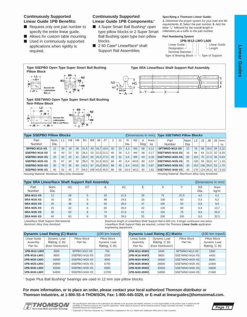
SPTWNO-M12-XS 12 76 56 19,5 28 0,22
SSETWNO-M16-XS 16 84 64 21,5 32 0,34
SSETWNO-M20-XS 20 104 76 27,0 38 0,63
SSETWNO-M25-XS 25 130 94 33,6 47 1,18
SSETWNO-M30-XS 30 152 106 39,5 53 1,70
SSETWNO-M40-XS 40 176 124 45,5 62 3,18
1PB-M12-MWO 2440 SPTWNO-M12-XS 1500
1PB-M16-MWO 8800 SSETWNO-M16-XS 4400
1PB-M20-MWO 16000 SSETWNO-M20-XS 8000
1PB-M25-MWO 26800 SSETWNO-M25-XS 13400
1PB-M30-MWO 33200 SSETWNO-M30-XS 16600
1PB-M40-MWO 54800 SSETWNO-M40-XS 27400
Dynamic Load Rating (C) Matrix (100 km travel)Linear Guide Dynamic Load Pillow Block Pillow Block
Assembly Rating, C (N) Part No. Dynamic Load Part No. (Even Distribution) Rating, C (N)
1PB-M12-LWO 3000 SPPBO-M12-XS 750
1PB-M16-LWO 8800 SSEPBO-M16-XS 2200
1PB-M20-LWO 16000 SSEPBO-M20-XS 4000
1PB-M25-LWO 26800 SSEPBO-M25-XS 6700
1PB-M30-LWO 33200 SSEPBO-M30-XS 8300
1PB-M40-LWO 54800 SSEPBO-M40-XS 13700
SRA-M12-XS 12 28 5 43 21,5 29 75 37,5 4,5 4,1
SRA-M16-XS 16 30 5 48 24,0 33 100 50 5,5 6,2
SRA-M20-XS 20 38 6 56 28,0 37 100 50 6,6 9,5
SRA-M25-XS 25 42 6 60 30,0 42 120 60 6,6 13,7
SRA-M30-XS 30 53 8 74 37,0 51 150 75 8,6 20,0
SRA-M40-XS 40 60 8 78 39,0 55 200 100 8,6 32,5
SPPBO-M12-XS 12 39 18 28 21,5 43 16,7 19,5 32 23 4,3 M5 66 0,11
SSEPBO-M16-XS 16 43 22 35 26,5 53 22,0 21,5 40 26 5,3 M6 66 0,17
SSEPBO-M20-XS 20 54 25 41 30,0 60 25,0 27,0 45 32 6,6 M8 60 0,30
SSEPBO-M25-XS 25 67 30 50 39,0 78 31,5 33,5 60 40 8,4 M10 60 0,57
SSEPBO-M30-XS 30 79 35 60 43,5 87 33,0 39,5 68 45 8,4 M10 60 0,87
SSEPBO-M40-XS 40 91 45 77 54,0 108 43,5 45,5 86 58 10,5 M12 60 1,62
The specifications and data in this publication are believed to be accurate and reliable. However, it is the responsibility of the product user to determine thesuitability of Thomson products for a specific application. While defective products will be replaced without charge if promptly returned, no liability is assumed beyond such replacement.
* Trademark of Thomson Industries, Inc. THOMSON is registered in the U.S. Patent and Trademark Office and in other countries.
Linear Guid
es
Page 71
For more information, or to place an order, please contact your local authorized Thomson distributor orThomson Industries, at 1-800-55-4-THOMSON, Fax: 1-800-445-0329, or E-mail at [email protected].
Continuously Supported Linear Guide 1PB Benefits:■ Requires only one part number to
specify the entire linear guide.■ Allows for custom table mounting■ Used in continuously supported
applications when rigidity isrequired.
Continuously Supported Linear Guide 1PB Components:†
■ 4 Super Smart Ball Bushing* opentype pillow blocks or 2 Super SmartBall Bushing open type twin pillowblocks.
■ 2 60 Case* LinearRace* shaftSupport Rail Assemblies.
Specifying a Thomson Linear Guide:1. Determine the proper system for your load and liferequirements. 2. Select the part number. 3. Add the letter “L” followed by the overall length inmillimeters,as a suffix to the part number.
Part Numbering System
1PB-M12-LWO L600Linear Guide Linear GuideDesignation LengthNominal Diameter
Type of Bearing Block Type of Support
Part Nom. H1 H7 A A1 E X Y N3 MassNumber Dia. Dia. kg/m
Type SRA LinearRace Shaft Support Rail Assembly (Dimensions in mm)
LinearRace Shaft Support Rail Material: Aluminum Alloy Grey Anodized
Maximum length of LinearRace Shaft Support Rail is 600 mm. If longer continuous one-pieceLinearRace Shaft Support Rails are required, contact the Thomson Linear Guide applicationengineering department.
Part Nom. L1 H8 H9 B1 B9 J6 J7 J J1 N N2 α MassNumber Dia. Dia. Deg kg
Type SSETWNO Pillow BlocksType SSEPBO Pillow Blocks (Dimensions in mm)
Housing Material: Aluminum Alloy Grey Anodized Housing Material: Aluminum Alloy Grey Anodized
Part Nom. L2 J3 J8 J9 Mass
Number Dia. kg
Dynamic Load Rating (C) Matrix (100 km travel)Linear Guide Dynamic Load Pillow Block Pillow Block
Assembly Rating, C (N) Part No. Dynamic Load Part No. (Even Distribution) Rating, C (N)
J3J9
L2 B9J
B1
N
H9
H8
α
N2
J8 J8
J6
Access forLubricationM6 x 1 (2 Plcs.)
B9J
B1
L1
N
J1N2
H9
H8
αJ7
J6Access forLubricationM6 x 1 Y X
EN3
H7H1
AA1
Type SSEPBO Open Type Super Smart Ball BushingPillow Block
Type SRA LinearRace Shaft Support Rail Assembly
Type SSETWNO Open Type Super Smart Ball BushingTwin Pillow Block
† Super Plus Ball Bushing* bearings are used in 12 mm size pillow blocks.

1PC-M12-LWF 3000 SPPBO-M12-XS 750
1PC-M16-LWF 8800 SSEPBO-M16-XS 2200
1PC-M20-LWF 16000 SSEPBO-M20-XS 4000
1PC-M25-LWF 26800 SSEPBO-M25-XS 6700
1PC-M30-LWF 33200 SSEPBO-M30-XS 8300
1PC-M40-LWF 54800 SSEPBO-M40-XS 13700
1PC-M12-MWE 2440 SPTWNO-M12-XS 1500
1PC-M16-MWE 8800 SSETWNO-M16-XS 4400
1PC-M20-MWE 16000 SSETWNO-M20-XS 8000
1PC-M25-MWE 26800 SSETWNO-M25-XS 13400
1PC-M30-MWE 33200 SSETWNO-M30-XS 16600
1PC-M40-MWE 54800 SSETWNO-M40-XS 27400
1PC-M12-MWE 12 56 28 43 21,5 98 22,5 55 100 76 L-(76) SPTWNO-M12-XS SRA-M12-XS1PC-M16-MWE 16 65 30 48 24,0 118 27,5 70 125 84 L-(84) SSETWNO-M16-XS SRA-M16-XS1PC-M20-MWE 20 79 38 56 28,0 166 32,5 110 175 104 L-(104) SSETWNO-M20-XS SRA-M20-XS1PC-M25-MWE 25 92 42 60 30,0 203 42,5 140 225 130 L-(130) SSETWNO-M25-XS SRA-M25-XS1PC-M30-MWE 30 108 53 74 37,0 254 47,5 180 275 152 L-(152) SSETWNO-M30-XS SRA-M30-XS1PC-M40-MWE 40 130 60 78 39,0 288 57,5 210 325 176 L-(176) SSETWNO-M40-XS SRA-M40-XS
1PC-M12-LWF 12 39 56 28 43 21,5 98 22,5 55 100 100 L-(100) SPPBO-M12-XS SRA-M12-XS1PC-M16-LWF 16 43 65 30 48 24,0 118 27,5 70 125 125 L-(125) SSEPBO-M16-XS SRA-M16-XS1PC-M20-LWF 20 54 79 38 56 28,0 166 32,0 110 175 175 L-(175) SSEPBO-M20-XS SRA-M20-XS1PC-M25-LWF 25 67 92 42 60 30,0 203 42,5 140 225 225 L-(225) SSEPBO-M25-XS SRA-M25-XS1PC-M30-LWF 30 79 108 53 74 37,0 254 47,5 180 275 275 L-(275) SSEPBO-M30-XS SRA-M30-XS1PC-M40-LWF 40 91 130 60 78 39,0 288 57,5 210 325 325 L-(325) SSEPBO-M40-XS SRA-M40-XS
Page 72The specifications and data in this publication are believed to be accurate and reliable. However, it is the responsibility of the product user to determine thesuitability of Thomson products for a specific application. While defective products will be replaced without charge if promptly returned, no liability is assumed beyond such replacement.
* Trademark of Thomson Industries, Inc. THOMSON is registered in the U.S. Patent and Trademark Office and in other countries.
Line
ar G
uid
es
For more information, or to place an order, please contact your local authorized Thomson distributor orThomson Industries, at 1-800-554-THOMSON, Fax: 1-800-445-0329, or E-mail at [email protected].
Continuous Support 1PCLinear Guide #6with Table TopFully Supported, Industry Standard Dimensions
T2
L1
T1 T
B
H
L
LB1
H1
A
B2
A1
Double Continuously Supported Linear Guide with 4 Pillow Blocks and Size F Table Top
Double Continuously Supported Linear Guidewith 2 Twin Pillow Blocks and Size E Table Top
Continuously Supported Linear Guide 1PC Double with 2 Twin Pillow Blocks and Table Top (Size E) (Dimensions in mm)
Part Nom. H H1 A A1 B B1 B2 T T2 Maximum Pillow ShaftNumber Dia. Stroke Block Support
Length RailAssembly
Continuously Supported Linear Guide 1PC Double with 4 Pillow Blocks and Table Top (Size F) (Dimensions in mm)
Part Nom. L1 H H1 A A1 B B1 B2 T T1 Maximum Pillow ShaftNumber Dia. Stroke Block Support
Length RailAssembly
METRIC
Dynamic Load Rating (C) Matrix (100 km travel)Linear Guide Dynamic Load Pillow Block Pillow Block
Assembly Rating, C (N) Part No. Dynamic Load Part No. (Even Distribution) Rating, C (N)
Dynamic Load Rating (C) Matrix (100 km travel)Linear Guide Dynamic Load Pillow Block Pillow Block
Assembly Rating, C (N) Part No. Dynamic Load Part No. (Even Distribution) Rating, C (N)
Load Rating andLimit by Direction
Dynamic Load RatingLoad value used in life calculation.Load LimitMaximum allowable load applied to bearing.
Fc Ft
Fs
FcFtFs
C0.5C
C
C0.5C0.5C
DynamicLoad Rating Load Limit

1PC-M12 100 55 32 10 M6 100 23 8,0 6,5 55 76 56 10 6,5 28 401PC-M16 125 70 40 13 M6 125 26 10,0 7,5 70 84 64 10 7,5 32 451PC-M20 175 110 45 16 M8 175 32 11,0 10,0 110 104 76 14 10,0 38 551PC-M25 225 140 60 20 M8 225 40 13,5 12,5 140 130 94 18 12,5 47 651PC-M30 275 180 68 20 M8 275 45 17,0 13,5 180 152 106 23 13,5 53 751PC-M40 325 210 86 25 M10 325 58 16,5 14,5 210 176 124 26 14,5 62 85
SRA-M12-XS 12 28 5 43 21,5 29 75 37,5 4,5 4,1
SRA-M16-XS 16 30 5 48 24,0 33 100 50 5,5 6,2
SRA-M20-XS 20 38 6 56 28,0 37 100 50 6,6 9,5
SRA-M25-XS 25 42 6 60 30,0 42 120 60 6,6 13,7
SRA-M30-XS 30 53 8 74 37,0 51 150 75 8,6 20,0
SRA-M40-XS 40 60 8 78 39,0 55 200 100 8,6 32,5
SPTWNO-M12-XS 12 76 56 19,5 28 0,22
SSETWNO-M16-XS 16 84 64 21,5 32 0,34
SSETWNO-M20-XS 20 104 76 27,0 38 0,63
SSETWNO-M25-XS 25 130 94 33,6 47 1,18
SSETWNO-M30-XS 30 152 106 39,5 53 1,70
SSETWNO-M40-XS 40 176 124 45,5 62 3,18
SPPBO-M12-XS 12 39 18 28 21,5 43 16,7 19,5 32 23 4,3 M5 66 0,11
SSEPBO-M16-XS 16 43 22 35 26,5 53 22,0 21,5 40 26 5,3 M6 66 0,17
SSEPBO-M20-XS 20 54 25 41 30,0 60 25,0 27,0 45 32 6,6 M8 60 0,30
SSEPBO-M25-XS 25 67 30 50 39,0 78 31,5 33,5 60 40 8,4 M10 60 0,57
SSEPBO-M30-XS 30 79 35 60 43,5 87 33,0 39,5 68 45 8,4 M10 60 0,87
SSEPBO-M40-XS 40 91 45 77 54,0 108 43,5 45,5 86 58 10,5 M12 60 1,62
The specifications and data in this publication are believed to be accurate and reliable. However, it is the responsibility of the product user to determine thesuitability of Thomson products for a specific application. While defective products will be replaced without charge if promptly returned, no liability is assumed beyond such replacement.
* Trademark of Thomson Industries, Inc. THOMSON is registered in the U.S. Patent and Trademark Office and in other countries.
Linear Guid
es
Page 73
For more information, or to place an order, please contact your local authorized Thomson distributor orThomson Industries, at 1-800-554-THOMSON, Fax: 1-800-445-0329, or E-mail at [email protected].
B9J
B1
L1
N
J1N2
H9
H8
αJ7
J6Access forLubricationM6 x 1
J3J9
L2 B9J
B1
N
H9
H8
α
N2
J8 J8
J6
Access forLubricationM6 x 1 (2 Plcs.)
Continuously Supported Linear Guide 1PC Benefits:■ Requires only one part number to
specify the entire linear guide.■ Includes table top with standard tapped
holes for quick and easy mounting of thework piece.
■ Includes Ball Screw Assembly attachmentholes for ease of assembly and actuation.
■ Used in continuously supported applications when rigidity is required.
Continuously Supported Linear Guide 1PC Components:†
■ 4 Super Smart Ball Bushing* open type pillow blocks or 2 Super Smart Ball Bushing open type twin pillow blocks.
■ 2 60 Case* LinearRace* shaft SupportRail Assemblies.
■ 1 mounting table top with work piece andBall Screw Assembly attachment holes.
Specifying a Thomson Linear Guide:1. Determine the proper system for your load and liferequirements. 2. Select the part number. 3. Add the letter “L” followed by the overall length inmillimeters,as a suffix to the part number.
Part Numbering System
1PC-M12-LWF L600Linear Guide Linear GuideDesignation LengthNominal Diameter Type of Table Top
Type of Bearing Block Type of Support
Y X
E
N3
H7H1
AA1 J
J5
H6
M
M1, M2T1, T2
J3
J9J1
F5
T
J4
Type SRA LinearRace Shaft Support Rail Assembly Mounting Table Top
Mounting Table Top (Dimensions in mm)
Material: Aluminum Alloy Grey Anodized(2) Customer Mounting hole.
Part Nom. H1 H7 A A1 E X Y N3 MassNumber Dia. Dia. kg/m
Type SRA LinearRace Shaft Support Rail Assembly (Dimensions in mm)
LinearRace Shaft Support Rail Material: Aluminum Alloy Grey Anodized
Maximum length of LinearRace Shaft Support Rail is 600 mm. If longer continuous one-piece LinearRaceShaft Support Rails are required, contact the Thomson Linear Guide application engineering department.
Part Nom. L1 H8 H9 B1 B9 J6 J7 J J1 N N2 α MassNumber Dia. Dia. Deg kg
Type SSETWNO Pillow BlocksType SSEPBO Pillow Blocks (Dimensions in mm)
Housing Material: Aluminum Alloy Grey Anodized Housing Material: Aluminum Alloy Grey Anodized
Part Nom. L2 J3 J8 J9 Mass
Number Dia. kg
Type SSEPBO Open Type Super Smart BallBushing Pillow Block
Type SSETWNO Open Type Super Smart BallBushing Twin Pillow Block
System All Table Tops Table Top Size F Table Top Size ET M J H6 F5(2) T1 J1 J4 J5 M1 T2 J3 J4 J5 J9 M2
† Super Plus Ball Bushing* bearings are used in 12 mm size pillow blocks.

BEL-1C-08 1/2 1.375 .968 2.062 .088BEL-1C-12 3/4 1.812 1.062 2.312 .120BEL-1C-16 1 2.375 1.218 2.625 .088BEL-1C-24 11/2 3.125 1.531 3.125 .088
Page 74The specifications and data in this publication are believed to be accurate and reliable. However, it is the responsibility of the product user to determine thesuitability of Thomson products for a specific application. While defective products will be replaced without charge if promptly returned, no liability is assumed beyond such replacement.
® Viton is a registered trademark of E.I. DuPont de Nemours & Company.* Trademark of Thomson Industries, Inc. THOMSON is registered in the U.S. Patent and Trademark Office and in other countries.
Line
ar G
uid
es -LL Self-Lubricating Option‡
The new LL Option provides maintenance-free operation and enhanced bearing protection.
• Eliminates the need for expensivelubrication system in most applications
• Increases effective bearing life byincreasing protection from contamination
• Environmentally friendly
NOTE: Carriage drag with the -LL option will beapproximately 2x the seal drag.
Continuous Support Ball Guide Accessories
For more information, or to place an order, please contact your local authorized Thomson distributor orThomson Industries, at 1-800-554-THOMSON, Fax: 1-800-445-0329, or E-mail at [email protected].
‡ See page 210 for technical data.
Bellows (Way Covers) Option
B1
B
H
H1
B
HH1
† Each moveable bellows comes with 1 section of bellows and 2 pairs of Velcro® Fasteners.
BEL-1C†
For Systems 1CA, 1CB, 1CC,2EA, 2EB
L
L1
SBEL-1C†
For Systems 1CA, 1CB, 1CC,2EA, 2EB
BEL-1C Moveable Protective BellowsPart Nom. Dimension (in.)
Number Shaft Dia. H H1 B
SBEL-1C Stationary Protective BellowsPart Nom. Dimension (in.)
Number Shaft Dia. H H1 B
SBEL-1C-08 1/2 1.125 0.656 2.062SBEL-1C-12 3/4 1.625 0.843 2.281SBEL-1C-16 1 2.250 1.031 2.625SBEL-1C-24 11/2 3.062 1.531 3.125
This illustration describes the properusage for stationary and moveablebellows for System 1CA.
Stationary Protective Bellows aredesigned to fit between two fixed pillow blocks and underneath the profile of the carrriage mounting top.
CR

The specifications and data in this publication are believed to be accurate and reliable. However, it is the responsibility of the product user to determine thesuitability of Thomson products for a specific application. While defective products will be replaced without charge if promptly returned, no liability is assumed beyond such replacement.
* Trademark of Thomson Industries, Inc. THOMSON is registered in the U.S. Patent and Trademark Office and in other countries.
Linear Guid
es
Page 75
For more information, or to place an order, please contact your local authorized Thomson distributor orThomson Industries, at 1-800-554-THOMSON, Fax: 1-800-445-0329, or E-mail at [email protected].
3
2
14
NEW
5NEW
67
911
12
13
1415
16
8NEW 10
NEW17NEW
Side Mounted Linear Ball Guides Offer:
Side Mounted Linear Ball Guides #7
LOW PROFILE, HIGH LOADS IN ALLDIRECTIONS, EASY TO INSTALL
■ Increased life within the same envelope.RoundRail* linear guides feature the new patented Super Smart Ball Bushing* bearingsfor up to 216X the life or 6X the load capacityof conventional bearings
■ Cost savings: save time and money preparingyour mounting surfaces before bolting downRoundRail linear guides
■ Side mounted geometry for increased mounting flexibility
■ Superior performance. Continuously supportedfor maximum (down- & side-) load applications without concerns for shaft deflection
■ The RoundRail Advantage*. The inherent self-aligning-in-all-directions design of theSuper Smart Ball Bushing bearing allows forultra smooth travel when mounted to wider toleranced prepared surfaces
■ Unlimited travel lengths without concerns formachined reference edges or butt joint alignment
■ The Super Smart Ball Bushing bearing…the most technologically advanced and mostrobust linear bearing in the world
■ Corrosion resistant versions for maximum performance in harsh environments.
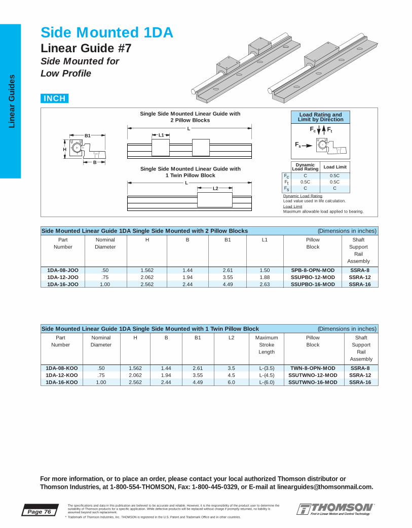
1DA-08-KOO .50 1.562 1.44 2.61 3.5 L-(3.5) TWN-8-OPN-MOD SSRA-81DA-12-KOO .75 2.062 1.94 3.55 4.5 L-(4.5) SSUTWNO-12-MOD SSRA-121DA-16-KOO 1.00 2.562 2.44 4.49 6.0 L-(6.0) SSUTWNO-16-MOD SSRA-16
1DA-08-JOO .50 1.562 1.44 2.61 1.50 SPB-8-OPN-MOD SSRA-81DA-12-JOO .75 2.062 1.94 3.55 1.88 SSUPBO-12-MOD SSRA-121DA-16-JOO 1.00 2.562 2.44 4.49 2.63 SSUPBO-16-MOD SSRA-16
Page 76The specifications and data in this publication are believed to be accurate and reliable. However, it is the responsibility of the product user to determine thesuitability of Thomson products for a specific application. While defective products will be replaced without charge if promptly returned, no liability is assumed beyond such replacement.
* Trademark of Thomson Industries, Inc. THOMSON is registered in the U.S. Patent and Trademark Office and in other countries.
Line
ar G
uid
es
For more information, or to place an order, please contact your local authorized Thomson distributor orThomson Industries, at 1-800-554-THOMSON, Fax: 1-800-445-0329, or E-mail at [email protected].
Side Mounted 1DALinear Guide #7Side Mounted for Low Profile
H
B1
B
L2 L
L1 L
Side Mounted Linear Guide 1DA Single Side Mounted with 2 Pillow Blocks (Dimensions in inches)
Part Nominal H B B1 L1 Pillow ShaftNumber Diameter Block Support
Rail Assembly
Side Mounted Linear Guide 1DA Single Side Mounted with 1 Twin Pillow Block (Dimensions in inches)
Part Nominal H B B1 L2 Maximum Pillow ShaftNumber Diameter Stroke Block Support
Length RailAssembly
Single Side Mounted Linear Guide with 2 Pillow Blocks
Single Side Mounted Linear Guide with 1 Twin Pillow Block
INCH
FcFtFs
C0.5C
C
0.5C0.5C
C
DynamicLoad Rating Load Limit
Load Rating andLimit by Direction
Fc Ft
Fs
Dynamic Load RatingLoad value used in life calculation.Load LimitMaximum allowable load applied to bearing.
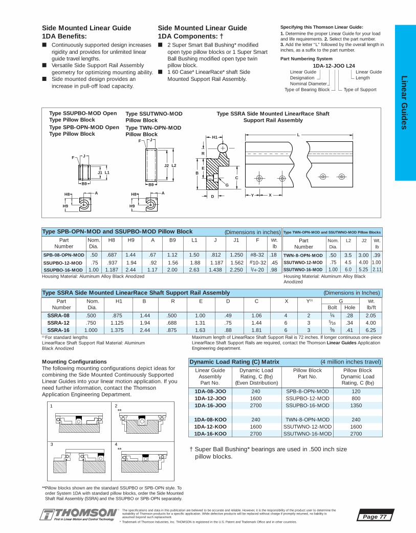
SSUPBO-16-MOD 1.00 1.187 2.44 1.17 2.00 2.63 1.438 2.250 1/4-20 .98
SPB-08-OPN-MOD .50 .687 1.44 .67 1.12 1.50 .812 1.250 #8-32 .18
1DA-08-JOO 240 SPB-8-OPN-MOD 1201DA-12-JOO 1600 SSUPBO-12-MOD 8001DA-16-JOO 2700 SSUPBO-16-MOD 1350
1DA-08-KOO 240 TWN-8-OPN-MOD 2401DA-12-KOO 1600 SSUTWNO-12-MOD 16001DA-16-KOO 2700 SSUTWNO-16-MOD 2700
SSRA-08 .500 .875 1.44 .500 1.00 .49 1.06 4 2 1⁄4 .28 2.05SSRA-12 .750 1.125 1.94 .688 1.31 .75 1.44 6 3 5⁄16 .34 4.00SSRA-16 1.000 1.375 2.44 .875 1.63 .88 1.81 6 3 3⁄8 .41 6.25
SSUTWNO-16-MOD 1.00 6.0 5.25 2.11
TWN-8-OPN-MOD .50 3.5 3.00 .39
The specifications and data in this publication are believed to be accurate and reliable. However, it is the responsibility of the product user to determine thesuitability of Thomson products for a specific application. While defective products will be replaced without charge if promptly returned, no liability is assumed beyond such replacement.
* Trademark of Thomson Industries, Inc. THOMSON is registered in the U.S. Patent and Trademark Office and in other countries.
Linear Guid
es
Page 77
J
J1 L1
L2
B
D
C
Y CX
L
G
E
H1
R
J2
B9 B9
H8 A
H9
F
JJF
H8 A
H9
Side Mounted Linear Guide 1DA Benefits:■ Continuously supported design increases
rigidity and provides for unlimited linearguide travel lengths.
■ Versatile Side Support Rail Assemblygeometry for optimizing mounting ability.
■ Side mounted design provides an increase in pull-off load capacity.
Side Mounted Linear Guide 1DA Components: †■ 2 Super Smart Ball Bushing* modified
open type pillow blocks or 1 Super Smart Ball Bushing modified open type twin pillow block.
■ 1 60 Case* LinearRace* shaft SideMounted Support Rail Assembly.
Specifying this Thomson Linear Guide:1. Determine the proper Linear Guide for your loadand life requirements. 2. Select the part number. 3. Add the letter “L” followed by the overall length ininches, as a suffix to the part number.
Part Numbering System
1DA-12-JOO L24Linear Guide Linear GuideDesignation LengthNominal Diameter
Type of Bearing Block Type of Support
SSUTWNO-12-MOD .75 4.5 4.00 1.00
Part Nom. L2 J2 Wt.Number Dia. lb
Part Nom. H8 H9 A B9 L1 J J1 F Wt.Number Dia. lb
Type TWN-OPN-MOD and SSUTWNO-MOD Pillow Blocks
SSUPBO-12-MOD .75 .937 1.94 .92 1.56 1.88 1.187 1.562 #10-32 .45
Type SPB-OPN-MOD and SSUPBO-MOD Pillow Block (Dimensions in inches)
Part Nom. H1 B R E D C X Y(1) G Wt.Number Dia. Bolt Hole lb/ft
Type SSRA Side Mounted LinearRace Shaft Support Rail Assembly (Dimensions in Inches)
(1) For standard lengths LinearRace Shaft Support Rail Material: Aluminum Black Anodized
Mounting ConfigurationsThe following mounting configurations depict ideas for combining the Side Mounted Continuously SupportedLinear Guides into your linear motion application. If youneed further information, contact the ThomsonApplication Engineering Department.
Housing Material: Aluminum Alloy Black Anodized Housing Material: Aluminum Alloy BlackAnodized
**Pillow blocks shown are the standard SSUPBO or SPB-OPN style. Toorder System 1DA with standard pillow blocks, order the Side MountedShaft Rail Assembly (SSRA) and the SSUPBO or SPB-OPN separately.
Type SSUPBO-MOD OpenType Pillow BlockType SPB-OPN-MOD OpenType Pillow Block
Type SSUTWNO-MOD Pillow BlockType TWN-OPN-MODPillow Block
Type SSRA Side Mounted LinearRace Shaft Support Rail Assembly
1
3
2
4
Maximum length of LinearRace Shaft Support Rail is 72 inches. If longer continuous one-pieceLinearRace Shaft Support Rails are required, contact the Thomson Linear Guides ApplicationEngineering department.
Dynamic Load Rating (C) Matrix (4 million inches travel)Linear Guide Dynamic Load Pillow Block Pillow Block
Assembly Rating, C (lbf) Part No. Dynamic Load Part No. (Even Distribution) Rating, C (lbf)
**
** † Super Ball Bushing* bearings are used in .500 inch size pillow blocks.

0.5C0.5C
C
1DB-08-KOO .50 1.562 1.44 2.61 3.5 L-(3.5) TWN-8-OPN-MOD SSRA-81DB-12-KOO .75 2.062 1.94 3.55 4.5 L-(4.5) SSUTWNO-12-MOD SSRA-121DB-16-KOO 1.00 2.562 2.44 4.49 6.0 L-(6.0) SSUTWNO-16-MOD SSRA-16
1DB-08-JOO .50 1.562 1.44 2.61 1.50 SPB-8-OPN-MOD SSRA-81DB-12-JOO .75 2.062 1.94 3.55 1.88 SSUPBO-12-MOD SSRA-121DB-16-JOO 1.00 2.562 2.44 4.49 2.63 SSUPBO-16-MOD SSRA-16
Page 78The specifications and data in this publication are believed to be accurate and reliable. However, it is the responsibility of the product user to determine thesuitability of Thomson products for a specific application. While defective products will be replaced without charge if promptly returned, no liability is assumed beyond such replacement.
* Trademark of Thomson Industries, Inc. THOMSON is registered in the U.S. Patent and Trademark Office and in other countries.
Line
ar G
uid
es
For more information, or to place an order, please contact your local authorized Thomson distributor orThomson Industries, at 1-800-554-THOMSON, Fax: 1-800-445-0329, or E-mail at [email protected].
Side Mounted 1DBLinear Guide #7Side Mounted for Low Profile
L2 L
L1 L
H
B1
B
Side Mounted Linear Guide 1DB Double Side Mounted with 4 Pillow Blocks (Dimensions in inches)
Part Nominal H B B1 L1 Pillow ShaftNumber Diameter Block Support
RailAssembly
Side Mounted Linear Guide 1DB Double Side Mounted with 2 Twin Pillow Blocks (Dimensions in inches)
Part Nominal H B B1 L2 Maximum Pillow ShaftNumber Diameter Stroke Block Support
Length Rail Assembly
Double Side Mounted Linear Guide with 4 Pillow Blocks
Double Side Mounted Linear Guide with 2 Twin Pillow Blocks
INCH
FcFtFs
C0.5C
C
DynamicLoad Rating Load Limit
Load Rating andLimit by Direction
Fc Ft
Fs
Dynamic Load RatingLoad value used in life calculation.Load LimitMaximum allowable load applied to bearing.
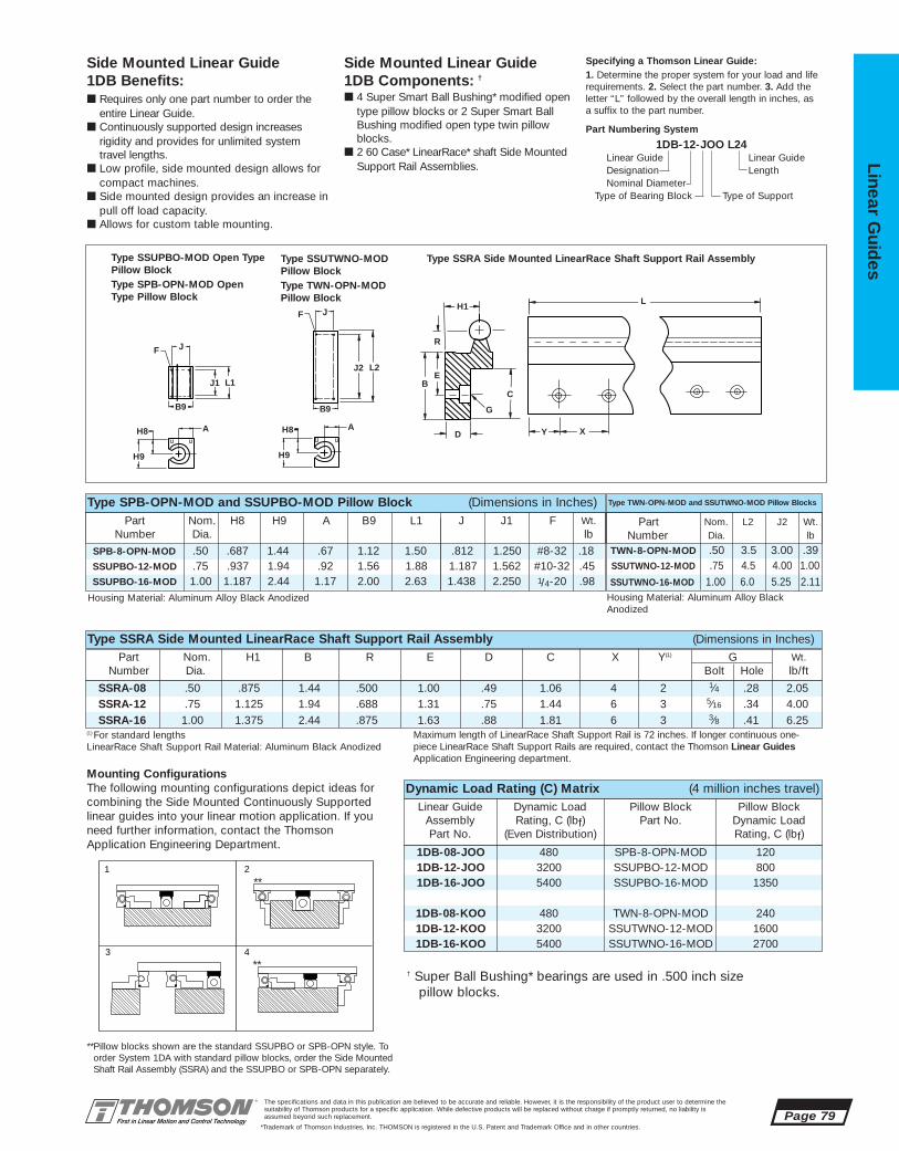
1DB-08-JOO 480 SPB-8-OPN-MOD 1201DB-12-JOO 3200 SSUPBO-12-MOD 8001DB-16-JOO 5400 SSUPBO-16-MOD 1350
1DB-08-KOO 480 TWN-8-OPN-MOD 2401DB-12-KOO 3200 SSUTWNO-12-MOD 16001DB-16-KOO 5400 SSUTWNO-16-MOD 2700
SSRA-08 .50 .875 1.44 .500 1.00 .49 1.06 4 2 1⁄4 .28 2.05SSRA-12 .75 1.125 1.94 .688 1.31 .75 1.44 6 3 5⁄16 .34 4.00SSRA-16 1.00 1.375 2.44 .875 1.63 .88 1.81 6 3 3⁄8 .41 6.25
SSUTWNO-16-MOD 1.00 6.0 5.25 2.11
TWN-8-OPN-MOD .50 3.5 3.00 .39SPB-8-OPN-MOD .50 .687 1.44 .67 1.12 1.50 .812 1.250 #8-32 .18
SSUPBO-16-MOD 1.00 1.187 2.44 1.17 2.00 2.63 1.438 2.250 1/4-20 .98
The specifications and data in this publication are believed to be accurate and reliable. However, it is the responsibility of the product user to determine thesuitability of Thomson products for a specific application. While defective products will be replaced without charge if promptly returned, no liability is assumed beyond such replacement.
*Trademark of Thomson Industries, Inc. THOMSON is registered in the U.S. Patent and Trademark Office and in other countries.
Linear Guid
es
Page 79
J
J1 L1
L2
B
D
C
Y CX
L
G
E
H1
R
J2
B9 B9
H8 A
H9
F
JJF
H8 A
H9
Side Mounted Linear Guide 1DB Components: †
■ 4 Super Smart Ball Bushing* modified opentype pillow blocks or 2 Super Smart BallBushing modified open type twin pillowblocks.
■ 2 60 Case* LinearRace* shaft Side MountedSupport Rail Assemblies.
Side Mounted Linear Guide 1DB Benefits:■ Requires only one part number to order the
entire Linear Guide.■ Continuously supported design increases
rigidity and provides for unlimited system travel lengths.
■ Low profile, side mounted design allows forcompact machines.
■ Side mounted design provides an increase inpull off load capacity.
■ Allows for custom table mounting.
Specifying a Thomson Linear Guide:1. Determine the proper system for your load and liferequirements. 2. Select the part number. 3. Add theletter “L” followed by the overall length in inches, asa suffix to the part number.
Part Numbering System
1DB-12-JOO L24Linear Guide Linear GuideDesignation LengthNominal Diameter
Type of Bearing Block Type of Support
SSUTWNO-12-MOD .75 4.5 4.00 1.00
Part Nom. H8 H9 A B9 L1 J J1 F Wt.Number Dia. lb
Type TWN-OPN-MOD and SSUTWNO-MOD Pillow Blocks
SSUPBO-12-MOD .75 .937 1.94 .92 1.56 1.88 1.187 1.562 #10-32 .45
Type SPB-OPN-MOD and SSUPBO-MOD Pillow Block (Dimensions in Inches)
Part Nom. L2 J2 Wt.Number Dia. lb
Part Nom. H1 B R E D C X Y(1) G Wt.Number Dia. Bolt Hole lb/ft
Type SSRA Side Mounted LinearRace Shaft Support Rail Assembly (Dimensions in Inches)
Housing Material: Aluminum Alloy Black Anodized Housing Material: Aluminum Alloy BlackAnodized
Type SSUPBO-MOD Open TypePillow BlockType SPB-OPN-MOD OpenType Pillow Block
Type SSUTWNO-MOD Pillow BlockType TWN-OPN-MODPillow Block
Type SSRA Side Mounted LinearRace Shaft Support Rail Assembly
(1) For standard lengths LinearRace Shaft Support Rail Material: Aluminum Black Anodized
Maximum length of LinearRace Shaft Support Rail is 72 inches. If longer continuous one-piece LinearRace Shaft Support Rails are required, contact the Thomson Linear GuidesApplication Engineering department.
Dynamic Load Rating (C) Matrix (4 million inches travel)Linear Guide Dynamic Load Pillow Block Pillow Block
Assembly Rating, C (lbf) Part No. Dynamic Load Part No. (Even Distribution) Rating, C (lbf)
Mounting ConfigurationsThe following mounting configurations depict ideas for combining the Side Mounted Continuously Supportedlinear guides into your linear motion application. If youneed further information, contact the ThomsonApplication Engineering Department.
**Pillow blocks shown are the standard SSUPBO or SPB-OPN style. Toorder System 1DA with standard pillow blocks, order the Side MountedShaft Rail Assembly (SSRA) and the SSUPBO or SPB-OPN separately.
1
3
2
4
**
**† Super Ball Bushing* bearings are used in .500 inch size
pillow blocks.
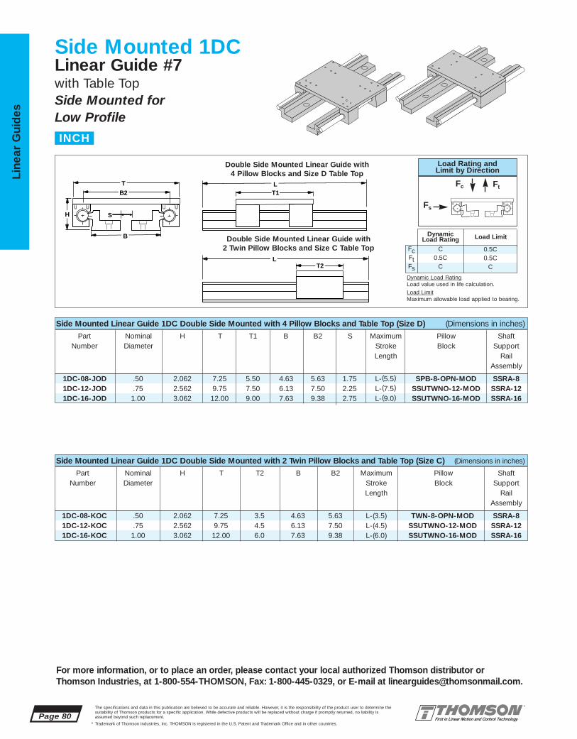
1DC-08-KOC .50 2.062 7.25 3.5 4.63 5.63 L-(3.5) TWN-8-OPN-MOD SSRA-81DC-12-KOC .75 2.562 9.75 4.5 6.13 7.50 L-(4.5) SSUTWNO-12-MOD SSRA-121DC-16-KOC 1.00 3.062 12.00 6.0 7.63 9.38 L-(6.0) SSUTWNO-16-MOD SSRA-16
1DC-08-JOD .50 2.062 7.25 5.50 4.63 5.63 1.75 L-(5.5) SPB-8-OPN-MOD SSRA-81DC-12-JOD .75 2.562 9.75 7.50 6.13 7.50 2.25 L-(7.5) SSUTWNO-12-MOD SSRA-121DC-16-JOD 1.00 3.062 12.00 9.00 7.63 9.38 2.75 L-(9.0) SSUTWNO-16-MOD SSRA-16
Page 80The specifications and data in this publication are believed to be accurate and reliable. However, it is the responsibility of the product user to determine thesuitability of Thomson products for a specific application. While defective products will be replaced without charge if promptly returned, no liability is assumed beyond such replacement.
* Trademark of Thomson Industries, Inc. THOMSON is registered in the U.S. Patent and Trademark Office and in other countries.
Line
ar G
uid
es
For more information, or to place an order, please contact your local authorized Thomson distributor orThomson Industries, at 1-800-554-THOMSON, Fax: 1-800-445-0329, or E-mail at [email protected].
Side Mounted 1DCLinear Guide #7with Table TopSide Mounted for Low Profile
T2 L
T1 L
H
B2
B
S
T
Side Mounted Linear Guide 1DC Double Side Mounted with 4 Pillow Blocks and Table Top (Size D) (Dimensions in inches)
Part Nominal H T T1 B B2 S Maximum Pillow ShaftNumber Diameter Stroke Block Support
Length RailAssembly
Side Mounted Linear Guide 1DC Double Side Mounted with 2 Twin Pillow Blocks and Table Top (Size C) (Dimensions in inches)
Part Nominal H T T2 B B2 Maximum Pillow ShaftNumber Diameter Stroke Block Support
Length RailAssembly
Double Side Mounted Linear Guide with 4 Pillow Blocks and Size D Table Top
Double Side Mounted Linear Guide with 2 Twin Pillow Blocks and Size C Table Top
INCH
0.5C0.5C
C
FcFtFs
C0.5C
C
DynamicLoad Rating Load Limit
Load Rating andLimit by Direction
Fc Ft
Fs
Dynamic Load RatingLoad value used in life calculation.Load LimitMaximum allowable load applied to bearing.

SSUTWNO-12-MOD .75 4.5 4.00 1.00TWN-8-OPN-MOD .50 3.5 3.00 .39
SSUTWNO-16--MOD 1.00 6.0 5.25 2.11SSUPBO-16-MOD 1.00 1.187 2.44 1.17 2.00 2.63 1.438 2.250 1/4-20 .98
SPB-08-OPN-MOD .50 .687 1.44 .67 1.12 1.50 .812 1.250 #8-32 .18
.50 7.25 4.0 .81 .50 1/4-20 5.5 1.25 .25 .28 2.63 3.5 3.00 .25 .28 .75
.75 9.75 6.0 1.19 .50 5/16-18 7.5 1.56 .25 .38 3.50 4.5 4.00 .25 .38 1.001.00 12.00 6.0 1.44 .50 3/8-16 9.0 2.25 .34 .40 4.38 6.0 5.25 .38 .40 1.25
1DC-08-JOD 480 SPB-8-OPN-MOD 1201DC-12-JOD 3200 SSUTWNO-12-MOD 8001DC-16-JOD 5400 SSUTWNO-16-MOD 1350
1DC-08-KOC 480 TWN-8-OPN-MOD 2401DC-12-KOC 3200 SSUTWNO-12-MOD 16001DC-16-KOC 5400 SSUTWNO-16-MOD 2700
SSRA-08 .500 .875 1.44 .500 1.00 .49 1.06 4 2 1⁄4 .28 2.05SSRA-12 .750 1.125 1.94 .688 1.31 .75 1.44 6 3 5⁄16 .34 4.00SSRA-16 1.000 1.375 2.44 .875 1.63 .88 1.81 6 3 3⁄8 .41 6.25
SSUPBO-12-MOD .75 .937 1.94 .92 1.56 1.88 1.187 1.562 #10-32 .45
The specifications and data in this publication are believed to be accurate and reliable. However, it is the responsibility of the product user to determine thesuitability of Thomson products for a specific application. While defective products will be replaced without charge if promptly returned, no liability is assumed beyond such replacement.
* Trademark of Thomson Industries, Inc. THOMSON is registered in the U.S. Patent and Trademark Office and in other countries.
Linear Guid
es
Page 81
J
J1 L1
L2
B
D
C
Y CX
L
G
E
H1
R
J2
B9 B9
H8 A
H9
F
JJF
H8 A
H9
Side Mounted Linear Guide 1DC Components:■ 4 Super Smart Ball Bushing* modified open
type pillow blocks or 2 Super Smart BallBushing modified open type twin pillowblocks.
■ 2 60 Case* LinearRace* shaft Side Mounted Support Rail Assemblies.
■ 1 mounting table top with work piece attachment holes.
Side Mounted Linear Guide 1DC Benefits:■ Requires only one part number to order the
entire linear guide.■ Continuously supported design increases
rigidity and provides for unlimited system travel lengths.
■ Low profile, side mounted design allows for compact machines.
■ Side mounted design provides an increase in pull-off load capacity.
■ Includes table top with standard tapped holes for quick and easy mounting of thework piece.
Specifying a Thomson Linear Guide:1. Determine the proper system for your load and liferequirements. 2. Select the part number. 3. Add theletter “L” followed by the overall length in inches, asa suffix to the part number.
Part Numbering System
1DC-12-JOD L24Linear Guide Linear GuideDesignation LengthNominal Diameter Type of Table Top
Type of Bearing Block Type of Support
Part Nom. L2 J2 Wt.Number Dia. lb
Part Nom. H8 H9 A B9 L1 J J1 F Wt.Number Dia. lb
Type TWN-OPN-MOD and SSUTWNO-MOD Pillow BlocksType SPB-OPN-MOD and SSUPBO-MOD Pillow Block (Dimensions in Inches)
Part Nom. H1 B R E D C X Y(1) G Wt.Number Dia. Bolt Hole lb/ft
Type SSRA Side Mounted LinearRace Shaft Support Rail Assembly (Dimensions in Inches)
Mounting Table Top (Dimensions in inches)
J
H6
M
N, N1
T1, T2
J1
J5
T
J3
J4
F5
(2) Mounting hole spacing facilitates attachment of Dual Shaft Rail 2DA Linear Guide in an X-Y orientation.
Type SSUPBO-MOD OpenType Pillow BlockType SPB-OPN-MOD OpenType Pillow Block
Type SSUTWNO-MOD Pillow BlockType TWN-OPN-MODPillow Block
Type SSRA Side Mounted LinearRace Shaft Support Rail Assembly
Mounting Table Top
(1) For standard lengths LinearRace Shaft Support Rail Material: Aluminum Black Anodized
Maximum length of LinearRace Shaft Support Rail is 72 inches. If longer continuousone-piece LinearRace Shaft Support Rails are required, contact the Thomson Linear GuideApplication Engineering department.
Dynamic Load Rating (C) Matrix (4 million inches travel)Linear Guide Dynamic Load Pillow Block Pillow Block
Assembly Rating, C (lbf) Part No. Dynamic Load Part No. (Even Distribution) Rating, C (lbf)
Nominal All Table Tops Table Top Size D Table Top Size CDiameter T M J H6 F5 T1 J1 J4 J5 N T2 J3 J4 J5 N1(2)
† Super Ball Bushing* bearings are used in.500 inch size pillow blocks.

Page 82The specifications and data in this publication are believed to be accurate and reliable. However, it is the responsibility of the product user to determine thesuitability of Thomson products for a specific application. While defective products will be replaced without charge if promptly returned, no liability is assumed beyond such replacement.
* Trademark of Thomson Industries, Inc. THOMSON is registered in the U.S. Patent and Trademark Office and in other countries.
Line
ar G
uid
es
-LL Self-Lubricating Option‡
The new LL Option provides maintenance-free operation and enhanced bearing protection.
• Eliminates the need for expensivelubrication system in most applications
• Increases effective bearing life byincreasing protection from contamination
• Environmentally friendly
NOTE: Carriage drag with the -LL option will beapproximately 2x the seal drag.
Side Mounted Linear Ball Guide Accessories
For more information, or to place an order, please contact your local authorized Thomson distributor orThomson Industries, at 1-800-554-THOMSON, Fax: 1-800-445-0329, or E-mail at [email protected].
‡ See page 210 for technical data.

The specifications and data in this publication are believed to be accurate and reliable. However, it is the responsibility of the product user to determine thesuitability of Thomson products for a specific application. While defective products will be replaced without charge if promptly returned, no liability is assumed beyond such replacement.
* Trademark of Thomson Industries, Inc. THOMSON is registered in the U.S. Patent and Trademark Office and in other countries.
Linear Guid
es
Page 83
3
2
1 4NEW
5NEW
6
79 11
12
13
14
15
16
8NEW
10NEW
17NEW
For more information, or to place an order, please contact your local authorized Thomson distributor orThomson Industries, at 1-800-554-THOMSON, Fax: 1-800-445-0329, or E-mail at [email protected].
Bolt From Bottom Linear Ball Guides Offer:
Bolt From Bottom Linear Ball Guides #8
LOW PROFILE, SMOOTH OPERATION, BOLT FROM BOTTOM
■ Bolt from bottom design to ensure maximumsealing area between the Super Smart BallBushing* bearing and the 60 Case*LinearRace* shaft
■ Increased life within the same envelope.RoundRail* linear guides feature the new patented Super Smart Ball Bushing bearingsfor up to 216X the life or 6X the load capacityof conventional bearings
■ The RoundRail Advantage*. The inherent self-aligning-in-all-directions design of theSuper Smart Ball Bushing bearing allows for ultra smooth travel when mounted to wider toleranced prepared surfaces
■ Cost savings: save time and money preparingyour mounting surfaces before bolting downRoundRail linear guides
■ Superior performance. Continuously supportedfor maximum down load applications withoutconcerns for shaft deflection
■ Unlimited travel lengths without concerns for machined reference edges or butt joint alignment
■ The Super Smart Ball Bushing bearing…themost technologically advanced and mostrobust linear bearing in the world
■ Corrosion resistant versions for maximum performance in harsh environments.
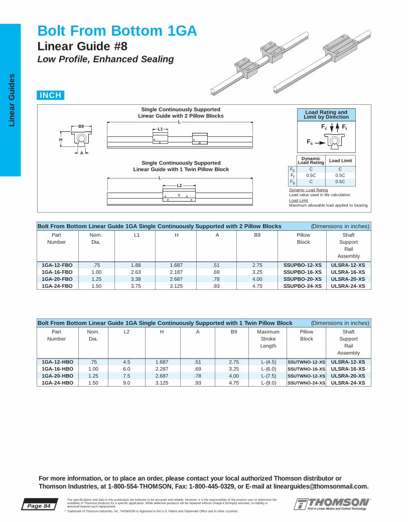
1GA-12-HBO .75 4.5 1.687 .51 2.75 L-(4.5) SSUTWNO-12-XS ULSRA-12-XS1GA-16-HBO 1.00 6.0 2.287 .69 3.25 L-(6.0) SSUTWNO-16-XS ULSRA-16-XS1GA-20-HBO 1.25 7.5 2.687 .78 4.00 L-(7.5) SSUTWNO-12-XS ULSRA-20-XS1GA-24-HBO 1.50 9.0 3.125 .93 4.75 L-(9.0) SSUTWNO-24-XS ULSRA-24-XS
1GA-12-FBO .75 1.88 1.687 .51 2.75 SSUPBO-12-XS ULSRA-12-XS1GA-16-FBO 1.00 2.63 2.187 .69 3.25 SSUPBO-16-XS ULSRA-16-XS1GA-20-FBO 1.25 3.38 2.687 .78 4.00 SSUPBO-20-XS ULSRA-20-XS1GA-24-FBO 1.50 3.75 3.125 .93 4.75 SSUPBO-24-XS ULSRA-24-XS
Page 84The specifications and data in this publication are believed to be accurate and reliable. However, it is the responsibility of the product user to determine thesuitability of Thomson products for a specific application. While defective products will be replaced without charge if promptly returned, no liability is assumed beyond such replacement.
* Trademark of Thomson Industries, Inc. THOMSON is registered in the U.S. Patent and Trademark Office and in other countries.
Line
ar G
uid
es
For more information, or to place an order, please contact your local authorized Thomson distributor orThomson Industries, at 1-800-554-THOMSON, Fax: 1-800-445-0329, or E-mail at [email protected].
Bolt From Bottom 1GALinear Guide #8Low Profile, Enhanced Sealing
L2
L1 B9
A
H
L
L
Bolt From Bottom Linear Guide 1GA Single Continuously Supported with 2 Pillow Blocks (Dimensions in inches)
Part Nom. L1 H A B9 Pillow ShaftNumber Dia. Block Support
RailAssembly
Bolt From Bottom Linear Guide 1GA Single Continuously Supported with 1 Twin Pillow Block (Dimensions in inches)
Part Nom. L2 H A B9 Maximum Pillow ShaftNumber Dia. Stroke Block Support
Length RailAssembly
Single Continuously Supported Linear Guide with 2 Pillow Blocks
Single Continuously Supported Linear Guide with 1 Twin Pillow Block
INCH
FcFtFs
C0.5C
C
C0.5C0.5C
DynamicLoad Rating Load Limit
Load Rating andLimit by Direction
Fc Ft
Fs
Dynamic Load RatingLoad value used in life calculation.Load LimitMaximum allowable load applied to bearing.
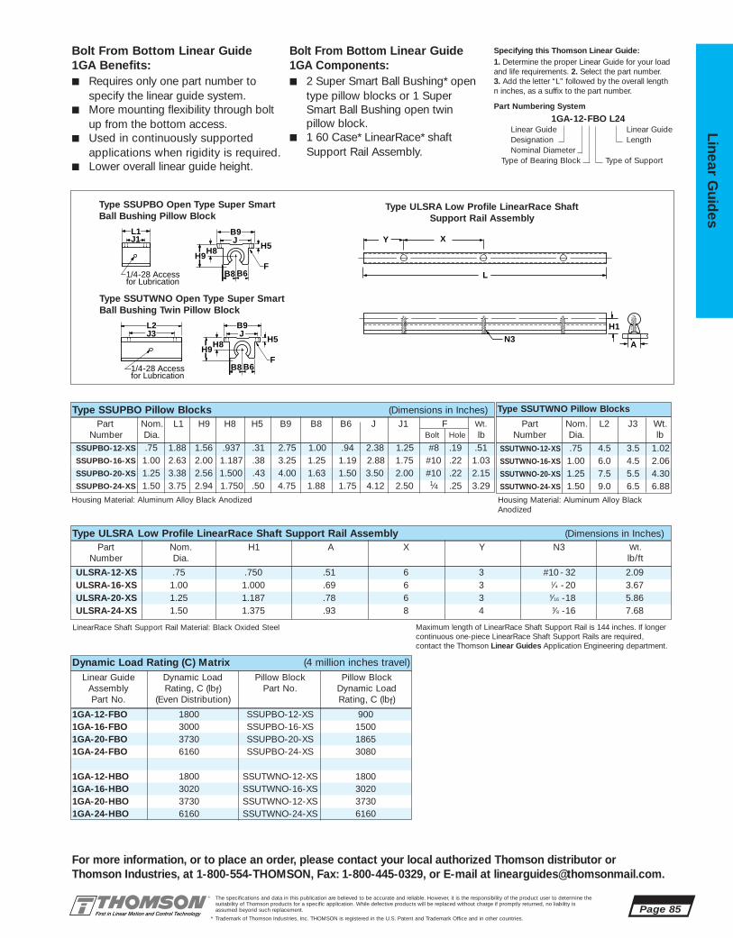
1GA-12-FBO 1800 SSUPBO-12-XS 9001GA-16-FBO 3000 SSUPBO-16-XS 15001GA-20-FBO 3730 SSUPBO-20-XS 18651GA-24-FBO 6160 SSUPBO-24-XS 3080
1GA-12-HBO 1800 SSUTWNO-12-XS 18001GA-16-HBO 3020 SSUTWNO-16-XS 30201GA-20-HBO 3730 SSUTWNO-12-XS 37301GA-24-HBO 6160 SSUTWNO-24-XS 6160
ULSRA-12-XS .75 .750 .51 6 3 #10 - 32 2.09ULSRA-16-XS 1.00 1.000 .69 6 3 1⁄4 -20 3.67ULSRA-20-XS 1.25 1.187 .78 6 3 5⁄16 -18 5.86ULSRA-24-XS 1.50 1.375 .93 8 4 3⁄8 -16 7.68
SSUTWNO-12-XS .75 4.5 3.5 1.02SSUTWNO-16-XS 1.00 6.0 4.5 2.06SSUTWNO-20-XS 1.25 7.5 5.5 4.30SSUTWNO-24-XS 1.50 9.0 6.5 6.88
SSUPBO-12-XS .75 1.88 1.56 .937 .31 2.75 1.00 .94 2.38 1.25 #8 .19 .51SSUPBO-16-XS 1.00 2.63 2.00 1.187 .38 3.25 1.25 1.19 2.88 1.75 #10 .22 1.03SSUPBO-20-XS 1.25 3.38 2.56 1.500 .43 4.00 1.63 1.50 3.50 2.00 #10 .22 2.15SSUPBO-24-XS 1.50 3.75 2.94 1.750 .50 4.75 1.88 1.75 4.12 2.50 1⁄4 .25 3.29
The specifications and data in this publication are believed to be accurate and reliable. However, it is the responsibility of the product user to determine thesuitability of Thomson products for a specific application. While defective products will be replaced without charge if promptly returned, no liability is assumed beyond such replacement.
* Trademark of Thomson Industries, Inc. THOMSON is registered in the U.S. Patent and Trademark Office and in other countries.
Linear Guid
es
Page 85
For more information, or to place an order, please contact your local authorized Thomson distributor orThomson Industries, at 1-800-554-THOMSON, Fax: 1-800-445-0329, or E-mail at [email protected].
N3
L
H1
A
X Y
Bolt From Bottom Linear Guide 1GA Benefits:■ Requires only one part number to
specify the linear guide system.■ More mounting flexibility through bolt
up from the bottom access.■ Used in continuously supported
applications when rigidity is required.■ Lower overall linear guide height.
Bolt From Bottom Linear Guide 1GA Components:■ 2 Super Smart Ball Bushing* open
type pillow blocks or 1 SuperSmart Ball Bushing open twinpillow block.
■ 1 60 Case* LinearRace* shaftSupport Rail Assembly.
Specifying this Thomson Linear Guide:1. Determine the proper Linear Guide for your loadand life requirements. 2. Select the part number.3. Add the letter “L” followed by the overall length n inches, as a suffix to the part number.
Part Numbering System
1GA-12-FBO L24Linear Guide Linear GuideDesignation LengthNominal Diameter
Type of Bearing Block Type of Support
Part Nom. L1 H9 H8 H5 B9 B8 B6 J J1 F Wt.Number Dia. Bolt Hole lb
Type SSUTWNO Pillow BlocksType SSUPBO Pillow Blocks (Dimensions in Inches)
Part Nom. H1 A X Y N3 Wt.Number Dia. lb/ft
Type ULSRA Low Profile LinearRace Shaft Support Rail Assembly (Dimensions in Inches)
Housing Material: Aluminum Alloy Black Anodized Housing Material: Aluminum Alloy BlackAnodized
LinearRace Shaft Support Rail Material: Black Oxided Steel Maximum length of LinearRace Shaft Support Rail is 144 inches. If longercontinuous one-piece LinearRace Shaft Support Rails are required,contact the Thomson Linear Guides Application Engineering department.
Type ULSRA Low Profile LinearRace Shaft Support Rail Assembly
Part Nom. L2 J3 Wt.Number Dia. lb
B8 B6
B9
H8 H9
JH5
F
L1 J1
B8 B6
B9
H8 H9
JH5
F
J3L2
1/4-28 Access for Lubrication
1/4-28 Access for Lubrication
Type SSUPBO Open Type Super Smart Ball Bushing Pillow Block
Type SSUTWNO Open Type Super SmartBall Bushing Twin Pillow Block
Dynamic Load Rating (C) Matrix (4 million inches travel)Linear Guide Dynamic Load Pillow Block Pillow Block
Assembly Rating, C (lbf) Part No. Dynamic LoadPart No. (Even Distribution) Rating, C (lbf)

1GB-12-HBO .75 4.5 1.687 .51 2.75 L-(4.5) SSUTWNO-12-XS ULSRA-12-XS1GB-16-HBO 1.00 6.0 2.287 .69 3.25 L-(6.0) SSUTWNO-16-XS ULSRA-16-XS1GB-20-HBO 1.25 7.5 2.687 .78 4.00 L-(7.5) SSUTWNO-20-XS ULSRA-20-XS1GB-24-HBO 1.50 9.0 3.125 .93 4.75 L-(9.0) SSUTWNO-24-XS ULSRA-24-XS
1GB-12-FBO .75 1.88 1.687 .51 2.75 SSUPBO-12-XS ULSRA-12-XS1GB-16-FBO 1.00 2.63 2.187 .69 3.25 SSUPBO-16-XS ULSRA-16-XS1GB-20-FBO 1.25 3.38 2.687 .78 4.00 SSUPBO-20-XS ULSRA-20-XS1GB-24-FBO 1.50 3.75 3.125 .93 4.75 SSUPBO-24-XS ULSRA-24-XS
Page 86The specifications and data in this publication are believed to be accurate and reliable. However, it is the responsibility of the product user to determine thesuitability of Thomson products for a specific application. While defective products will be replaced without charge if promptly returned, no liability is assumed beyond such replacement.
* Trademark of Thomson Industries, Inc. THOMSON is registered in the U.S. Patent and Trademark Office and in other countries.
Line
ar G
uid
es
For more information, or to place an order, please contact your local authorized Thomson distributor orThomson Industries, at 1-800-554-THOMSON, Fax: 1-800-445-0329, or E-mail at [email protected].
Bolt From Bottom 1GBLinear Guide #8Low Profile, Enhanced Sealing
L2
L1
L
LB9
A
H
Bolt From Bottom Linear Guide 1GB Double Continuously Supported with 4 Pillow Blocks (Dimensions in inches)
Part Nom. L1 H A B9 Pillow ShaftNumber Dia. Block Support
RailAssembly
Bolt From Bottom Linear Guide 1GB Double Continuously Supported with 2 Twin Pillow Blocks (Dimensions in inches)
Part Nom. L2 H A B9 Maximum Pillow ShaftNumber Dia. Stroke Block Support
Length RailAssembly
Double Continuously Supported Linear Guide with 4 Pillow Blocks
Double Continuously Supported Linear Guidewith 2 Twin Pillow Blocks
INCH
FcFtFs
C0.5C
C
C0.5C0.5C
DynamicLoad Rating Load Limit
Load Rating andLimit by Direction
Fc Ft
Fs
Dynamic Load RatingLoad value used in life calculation.Load LimitMaximum allowable load applied to bearing.

1GB-12-FBO 3600 SSUPBO-12-XS 9001GB-16-FBO 6000 SSUPBO-16-XS 15001GB-20-FBO 7460 SSUPBO-20-XS 18651GB-24-FBO 12320 SSUPBO-24-XS 3080
1GB-12-HBO 3600 SSUTWNO-12-XS 18001GB-16-HBO 6040 SSUTWNO-16-XS 30201GB-20-HBO 7460 SSUTWNO-12-XS 37301GB-24-HBO 12320 SSUTWNO-24-XS 6160
ULSRA-12-XS .75 .750 .51 6 3 #10 - 32 2.09ULSRA-16-XS 1.00 1.000 .69 6 3 1⁄4 -20 3.67ULSRA-20-XS 1.25 1.187 .78 6 3 5⁄16 -18 5.86ULSRA-24-XS 1.50 1.375 .93 8 4 3⁄8 -16 7.68
SSUTWNO-12-XS .75 4.5 3.5 1.02SSUTWNO-16-XS 1.00 6.0 4.5 2.06SSUTWNO-20-XS 1.25 7.5 5.5 4.30SSUTWNO-24-XS 1.50 9.0 6.5 6.88
SSUPBO-12-XS .75 1.88 1.56 .937 .31 2.75 1.00 .94 2.38 1.25 #8 .19 .51SSUPBO-16-XS 1.00 2.63 2.00 1.187 .38 3.25 1.25 1.19 2.88 1.75 #10 .22 1.03SSUPBO-20-XS 1.25 3.38 2.56 1.500 .43 4.00 1.63 1.50 3.50 2.00 #10 .23 2.15SSUPBO-24-XS 1.50 3.75 2.94 1.750 .50 4.75 1.88 1.75 4.12 2.50 1⁄4 .25 3.20
The specifications and data in this publication are believed to be accurate and reliable. However, it is the responsibility of the product user to determine thesuitability of Thomson products for a specific application. While defective products will be replaced without charge if promptly returned, no liability is assumed beyond such replacement.
* Trademark of Thomson Industries, Inc. THOMSON is registered in the U.S. Patent and Trademark Office and in other countries.
Linear Guid
es
Page 87
For more information, or to place an order, please contact your local authorized Thomson distributor orThomson Industries, at 1-800-554-THOMSON, Fax: 1-800-445-0329, or E-mail at [email protected].
N3
L
H1
A
X Y
B8 B6
B9
H8 H9
JH5
F
L1
Access forLubrication
J1
B8 B6
B9
H8 H9
JH5
F
J3L2
Access forLubrication
Bolt From Bottom Linear Guide 1GB Benefits:■ Requires only one part number to
specify the entire linear guide.■ More mounting flexibility through
bolt up from the bottom access.■ Used in continuously supported
applications when rigidity isrequired.
■ Lower overall linear guide height.
Bolt From Bottom Linear Guide 1GB Components:■ 4 Super Smart Ball Bushing*
bearing open type pillow blocks or 2 Super Smart Ball Bushing opentype twin pillow blocks.
■ 2 60 Case* LinearRace* shaftSupport Rail Assemblies.
Specifying a Thomson Linear Guide:1. Determine the proper system for your load and liferequirements. 2. Select the part number. 3. Add theletter “L” followed by the overall length in inches, asa suffix to the part number.
Part Numbering System
1GB-12-FBO L24Linear Guide Linear GuideDesignation LengthNominal Diameter
Type of Bearing Block Type of Support
LinearRace Shaft Support Rail Material: Black Oxidized Steel Maximum length of LinearRace Shaft Support Rail is 144 inches. If longercontinuous one-piece LinearRace Shaft Support Rails are required, contact the Thomson Linear Guide Application Engineering department.
Type ULSRA Low Profile LinearRace Shaft Support Rail Assembly
Part Nom. L1 H9 H8 H5 B9 B8 B6 J J1 F Wt.Number Dia. Bolt Hole lb
Type SSUTWNO Pillow BlocksType SSUPBO Pillow Blocks (Dimensions in Inches)
Housing Material: Aluminum Alloy Black Anodized Housing Material: Aluminum Alloy BlackAnodized
Part Nom. L2 J3 Wt.Number Dia. lb
Part Nom. H1 A X Y N3 Wt.Number Dia. lb/ft
Type ULSRA Low Profile LinearRace Shaft Support Rail Assembly (Dimensions in Inches)
B8 B6
B9
H8 H9
JH5
F
L1 J1
B8 B6
B9
H8 H9
JH5
F
J3L2
1/4-28 Access for Lubrication
1/4-28 Access for Lubrication
Type SSUPBO Open Type Super Smart Ball Bushing Pillow Block
Type SSUTWNO Open Type Super SmartBall Bushing Twin Pillow Block
Dynamic Load Rating (C) Matrix (4 million inches travel)Linear Guide Dynamic Load Pillow Block Pillow Block
Assembly Rating, C (lbf) Part No. Dynamic LoadPart No. (Even Distribution) Rating, C (lbf)

1GC-12-FBB 3600 SSUPBO-12-XS 9001GC-16-FBB 6000 SSUPBO-16-XS 15001GC-20-FBB 7460 SSUPBO-20-XS 18651GC-24-FBB 12320 SSUPBO-24-XS 30801GC-12-HBA 3600 SSUTWNO-12-XS 18001GC-16-HBA 6040 SSUTWNO-16-XS 30201GC-20-HBA 7460 SSUTWNO-12-XS 37301GC-24-HBA 12320 SSUTWNO-24-XS 6160
1GC-12-HBA .75 .51 4.5 7.5 2.187 .750 5.01 4.50 L-(4.5) SSUTWNO-12-XS ULSRA-12-XS1GC-16-HBA 1.00 .69 6.0 9.0 2.687 1.000 6.19 5.50 L-(6.0) SSUTWNO-16-XS ULSRA-16-XS1GC-20-HBA 1.25 .78 7.5 11.0 3.437 1.187 7.53 6.75 L-(7.5) SSUTWNO-20-XS ULSRA-20-XS1GC-24-HBA 1.50 .93 9.0 13.0 3.875 1.375 8.93 8.00 L-(9.0) SSUTWNO-24-XS ULSRA-24-XS
1GC-12-FBB .75 .51 7.5 7.5 2.187 .750 5.01 4.50 1.88 L-(7.5) SSUPBO-12-XS ULSRA-12-XS1GC-16-FBB 1.00 .69 9.0 9.0 2.687 1.000 6.19 5.50 2.63 L-(9.0) SSUPBO-16-XS ULSRA-16-XS1GC-20-FBB 1.25 .78 11.0 11.0 3.437 1.187 7.53 6.75 3.38 L-(11.0) SSUPBO-20-XS ULSRA-20-XS1GC-24-FBB 1.50 .93 13.0 13.0 3.875 1.375 8.93 8.00 3.75 L-(13.0) SSUPBO-24-XS ULSRA-24-XS
Page 88The specifications and data in this publication are believed to be accurate and reliable. However, it is the responsibility of the product user to determine thesuitability of Thomson products for a specific application. While defective products will be replaced without charge if promptly returned, no liability is assumed beyond such replacement.
* Trademark of Thomson Industries, Inc. THOMSON is registered in the U.S. Patent and Trademark Office and in other countries.
Line
ar G
uid
es
For more information, or to place an order, please contact your local authorized Thomson distributor orThomson Industries, at 1-800-554-THOMSON, Fax: 1-800-445-0329, or E-mail at [email protected].
Bolt From Bottom 1GCLinear Guide #8with Table TopLow Profile, Enhanced Sealing
T1
L1
L
T2 L
T
A
H
B2
H1
B
Bolt From Bottom Linear Guide 1GC Double Continuously Supported with 4 Pillow Blocks and Table Top (Size B) (Dimensions in inches)
Part Nom. A T1 T H H1 B B2 L1 Maximum Pillow ShaftNumber Dia. Stroke Block Support
Length RailAssembly
Bolt From Bottom Linear Guide 1FC Double Continuously Supported with 2 Twin Pillow Blocks and Table Top (Size A) (Dimensions in inches)
Part Nom. A T2 T H H1 B B2 Maximum Pillow ShaftNumber Dia. Stroke Block Support
Length RailAssembly
Double Continuously Supported Linear Guide with 4 Pillow Blocks and Size B Table Top
Double Continuously Supported Linear Guide with 2 Twin Pillow Blocks and Size A Table Top
INCH
FcFtFs
C0.5C
C
C0.5C0.5C
DynamicLoad Rating Load Limit
Load Rating andLimit by Direction
Fc Ft
Fs
Dynamic Load RatingLoad value used in life calculation.Load LimitMaximum allowable load applied to bearing.
Dynamic Load Rating (C) Matrix (4 million inches travel)Linear Guide Dynamic Load Pillow Block Pillow Block
Assembly Rating, C (lbf) Part No. Dynamic LoadPart No. (Even Distribution) Rating, C (lbf)
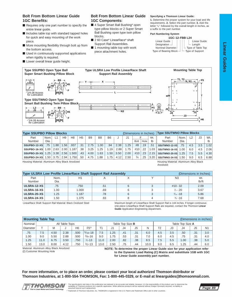
.75 7.5 4.50 2.38 .500 5/16-18 7.5 1.25 .41 .31 6.0 4.5 3.5 .50 .31 3.01.00 9.0 5.50 2.88 .500 3/8-16 9.0 1.75 .53 .31 7.0 6.0 4.5 .75 .31 4.01.25 11.0 6.75 3.50 .750 1⁄2-13 11.0 2.00 .82 .38 8.5 7.5 5.5 1.00 .38 5.01.50 13.0 8.00 4.12 .750 1/2-13 13.0 2.50 .75 .44 10.0 9.0 6.5 1.25 .44 6.0
Nominal All Table Tops Table Top Size B Table Top Size ADiameter T M J H6 F5(2) T1 J1 J4 J5 N T2 J3 J4 J5 N1
Mounting Table Top (Dimensions in inches)
Material: Aluminum Alloy Black Anodized(2) Customer Mounting Hole
NOTE: To determine the proper Linear Guide size for your application referto the Dynamic Load Rating (C) Matrix and substitiute 1GB with 1GCfor Linear Guide assembly part number.
ULSRA-12-XS .75 .750 .51 6 3 #10 - 32 2.09ULSRA-16-XS 1.00 1.000 .69 6 3 1⁄4 -20 3.67ULSRA-20-XS 1.25 1.187 .78 6 3 5⁄16 -18 5.86ULSRA-24-XS 1.50 1.375 .93 8 4 3⁄8 -16 7.68
SSUTWNO-12-XS .75 4.5 3.5 1.02SSUTWNO-16-XS 1.00 6.0 4.5 2.06SSUTWNO-20-XS 1.25 7.5 5.5 4.30SSUTWNO-24-XS 1.50 9.0 6.5 6.88
SSUPBO-12-XS .75 1.88 1.56 .937 .31 2.75 1.00 .94 2.38 1.25 #8 .19 .51SSUPBO-16-XS 1.00 2.63 2.00 1.187 .38 3.25 1.25 1.19 2.88 1.75 #10 .22 1.03SSUPBO-20-XS 1.25 3.38 2.56 1.500 .43 4.00 1.63 1.50 3.50 2.00 #10 .23 2.15SSUPBO-24-XS 1.50 3.75 2.94 1.750 .50 4.75 1.88 1.75 4.12 2.50 1⁄4 .25 3.20
The specifications and data in this publication are believed to be accurate and reliable. However, it is the responsibility of the product user to determine thesuitability of Thomson products for a specific application. While defective products will be replaced without charge if promptly returned, no liability is assumed beyond such replacement.
* Trademark of Thomson Industries, Inc. THOMSON is registered in the U.S. Patent and Trademark Office and in other countries.
Linear Guid
es
Page 89
For more information, or to place an order, please contact your local authorized Thomson distributor orThomson Industries, at 1-800-554-THOMSON, Fax: 1-800-445-0329, or E-mail at [email protected].
N3
L
H1
A
X Y
B8 B6
B9
H8 H9
JH5
F
L1 J1
B8 B6
B9
H8 H9
JH5
F
J3L2
J
J5
H6
M
N, N1
J3J1
F5
T
J4
T1, T2
1/4-28 Access for Lubrication
1/4-28 Access for Lubrication
Bolt From Bottom Linear Guide 1GC Components:■ 4 Super Smart Ball Bushing* open
type pillow blocks or 2 Super Smart Ball Bushing open type twin pillowblocks.
■ 2 60 Case* LinearRace* shaft Support Rail Assemblies.
■ 1 mounting table top with workpiece attachment holes.
Bolt From Bottom Linear Guide 1GC Benefits:■ Requires only one part number to specify the
entire linear guide.■ Includes table top with standard tapped holes
for quick and easy mounting of the workpiece.
■ More mounting flexibility through bolt up fromthe bottom access.
■ Used in continuously supported applicationswhen rigidity is required.
■ Lower overall linear guide height.
Specifying a Thomson Linear Guide:1. Determine the proper system for your load and liferequirements. 2. Select the part number. 3. Add theletter “L” followed by the overall length in inches, asa suffix to the part number.
Part Numbering System
1GC-12-FBB L24Linear Guide Linear GuideDesignation LengthNominal Diameter Type of Table Top
Type of Bearing Block Type of Support
Type SSUPBO Open Type BallSuper Smart Bushing Pillow Block
Type SSUTWNO Open Type SuperSmart Ball Bushing Twin Pillow Block
Type ULSRA Low Profile LinearRace Shaft Support Rail Assembly
Mounting Table Top
LinearRace Shaft Support Rail Material: Black Oxidized Steel Maximum length of LinearRace Shaft Support Rail is 144 inches. If longer continuousone-piece LinearRace Shaft Support Rails are required, contact the Thomson LinearGuide Application Engineering department.
Part Nom. H1 A X Y N3 Wt.Number Dia. lb/ft
Type ULSRA Low Profile LinearRace Shaft Support Rail Assembly (Dimensions in Inches)
Part Nom. L1 H9 H8 H5 B9 B8 B6 J J1 F Wt.Number Dia. Bolt Hole lb
Type SSUTWNO Pillow BlocksType SSUPBO Pillow Blocks (Dimensions in Inches)
Housing Material: Aluminum Alloy Black Anodized Housing Material: Aluminum Alloy BlackAnodized
Part Nom. L2 J3 Wt.Number Dia. lb
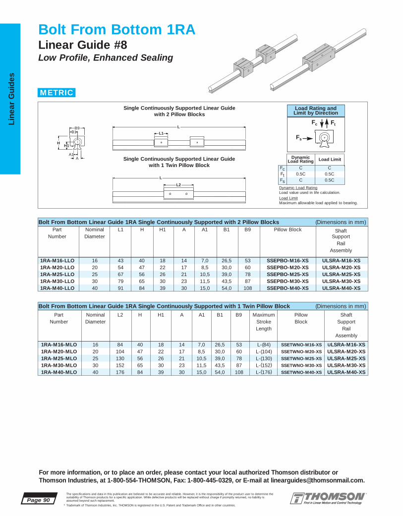
1RA-M16-MLO 16 84 40 18 14 7,0 26,5 53 L-(84) SSETWNO-M16-XS ULSRA-M16-XS1RA-M20-MLO 20 104 47 22 17 8,5 30,0 60 L-(104) SSETWNO-M20-XS ULSRA-M20-XS1RA-M25-MLO 25 130 56 26 21 10,5 39,0 78 L-(130) SSETWNO-M25-XS ULSRA-M25-XS1RA-M30-MLO 30 152 65 30 23 11,5 43,5 87 L-(152) SSETWNO-M30-XS ULSRA-M30-XS1RA-M40-MLO 40 176 84 39 30 15,0 54,0 108 L-(176) SSETWNO-M40-XS ULSRA-M40-XS
1RA-M16-LLO 16 43 40 18 14 7,0 26,5 53 SSEPBO-M16-XS ULSRA-M16-XS1RA-M20-LLO 20 54 47 22 17 8,5 30,0 60 SSEPBO-M20-XS ULSRA-M20-XS1RA-M25-LLO 25 67 56 26 21 10,5 39,0 78 SSEPBO-M25-XS ULSRA-M25-XS1RA-M30-LLO 30 79 65 30 23 11,5 43,5 87 SSEPBO-M30-XS ULSRA-M30-XS1RA-M40-LLO 40 91 84 39 30 15,0 54,0 108 SSEPBO-M40-XS ULSRA-M40-XS
Page 90The specifications and data in this publication are believed to be accurate and reliable. However, it is the responsibility of the product user to determine thesuitability of Thomson products for a specific application. While defective products will be replaced without charge if promptly returned, no liability is assumed beyond such replacement.
* Trademark of Thomson Industries, Inc. THOMSON is registered in the U.S. Patent and Trademark Office and in other countries.
Line
ar G
uid
es
For more information, or to place an order, please contact your local authorized Thomson distributor orThomson Industries, at 1-800-554-THOMSON, Fax: 1-800-445-0329, or E-mail at [email protected].
Bolt From Bottom 1RALinear Guide #8Low Profile, Enhanced Sealing
L2
L1 B9
B1
A A1
H H1
L
L
Bolt From Bottom Linear Guide 1RA Single Continuously Supported with 2 Pillow Blocks (Dimensions in mm)Part Nominal L1 H H1 A A1 B1 B9 Pillow Block Shaft
Number Diameter SupportRail
Assembly
Bolt From Bottom Linear Guide 1RA Single Continuously Supported with 1 Twin Pillow Block (Dimensions in mm)
Part Nominal L2 H H1 A A1 B1 B9 Maximum Pillow ShaftNumber Diameter Stroke Block Support
Length RailAssembly
Single Continuously Supported Linear Guide with 2 Pillow Blocks
Single Continuously Supported Linear Guide with 1 Twin Pillow Block
METRIC
FcFtFs
C0.5C
C
C0.5C0.5C
DynamicLoad Rating Load Limit
Load Rating andLimit by Direction
Fc Ft
Fs
Dynamic Load RatingLoad value used in life calculation.Load LimitMaximum allowable load applied to bearing.

SSETWNO-M16-XS 16 84 64 21,5 32 0,34
SSETWNO-M20-XS 20 104 76 27,0 38 0,63
SSETWNO-M25-XS 25 130 94 33,6 47 1,18
SSETWNO-M30-XS 30 152 106 39,5 53 1,70
SSETWNO-M40-XS 40 176 124 45,5 62 3,18
1RA-M16-MLO 4400 SSETWNO-M16-XS 44001RA-M20-MLO 8000 SSETWNO-M20-XS 80001RA-M25-MLO 13400 SSETWNO-M25-XS 134001RA-M30-MLO 16600 SSETWNO-M30-XS 166001RA-M40-MLO 27400 SSETWNO-M40-XS 27400
1RA-M16-LLO 4400 SSEPBO-M16-XS 22001RA-M20-LLO 8000 SSEPBO-M20-XS 40001RA-M25-LLO 13400 SSEPBO-M25-XS 67001RA-M30-LLO 16600 SSEPBO-M30-XS 83001RA-M40-LLO 27400 SSEPBO-M40-XS 13700
ULSRA-M16-XS 16 18 14 7,0 100 20 M3 x 30 3,6ULSRA-M20-XS 20 22 17 8,5 100 30 M4 x 35 5,5ULSRA-M25-XS 25 26 21 10,5 120 30 M5 x 45 8,5ULSRA-M30-XS 30 30 23 11,5 150 40 M6 x 50 13,0ULSRA-M40-XS 40 39 30 15,0 200 52,5 M10 x 65 21,0
SSEPBO-M16-XS 16 43 22 35 26,5 53 22,0 21,5 40 26 5,3 M6 66 0,17
SSEPBO-M20-XS 20 54 25 41 30,0 60 25,0 27,0 45 32 6,6 M8 60 0,30
SSEPBO-M25-XS 25 67 30 50 39,0 78 31,5 33,5 60 40 8,4 M10 60 0,57
SSEPBO-M30-XS 30 79 35 60 43,5 87 33,0 39,5 68 45 8,4 M10 60 0,87
SSEPBO-M40-XS 40 91 45 77 54,0 108 43,5 45,5 86 58 10,5 M12 60 1,62
The specifications and data in this publication are believed to be accurate and reliable. However, it is the responsibility of the product user to determine thesuitability of Thomson products for a specific application. While defective products will be replaced without charge if promptly returned, no liability is assumed beyond such replacement.
* Trademark of Thomson Industries, Inc. THOMSON is registered in the U.S. Patent and Trademark Office and in other countries.
Linear Guid
es
Page 91
For more information, or to place an order, please contact your local authorized Thomson distributor orThomson Industries, at 1-800-554-THOMSON, Fax: 1-800-445-0329, or E-mail at [email protected].
J3J9
B9J
B1
L1
L2
N
J1N2
B9J
B1
N
H9
H8
H9
H8
α
α
N2
J7
J6Access forLubricationM6 x 1
J8 J8
J6
Access forLubricationM6 x 1 (2 Plcs.)
Bolt From Bottom Linear Guide 1RA Components:■ 2 Super Smart Ball Bushing* open
type pillow blocks or 1 Super SmartBall Bushing open type twin pillowblock.
■ 1 60 Case* LinearRace* shaftSupport Rail Assembly.
Bolt From Bottom Linear Guide 1RA Benefits:■ Requires only one part number to
specify the entire linear guide.■ Used to provide increased stability
or torque resistance in linear system applications.
■ Used in continuously supportedapplications when rigidity isrequired.
■ Lower overall linear guide height.
Specifying a Thomson Linear Guide:1. Determine the proper system for your load and life requirements. 2. Select the part number. 3. Add the letter “L” followed by the overall lengthin millimeters, as a suffix to the part number.
Part Numbering System
1RA-M16-LLO L600Linear Guide Linear GuideDesignation LengthNominal Diameter
Type of Bearing Block Type of Support
Part Nom. L1 H8 H9 B1 B9 J6 J7 J J1 N N2 α MassNumber Dia. Dia. Deg kg
Type SSETWNO Pillow BlocksType SSEPBO Pillow Blocks (Dimensions in mm)
Y X
L
H1
A
N3
Housing Material: Aluminum Alloy Grey Anodized Housing Material: Aluminum Alloy Grey Anodized
Type SSEPBO Open Type Super Smart Ball Bushing Pillow Block
Type ULSRA Low Profile LinearRace Shaft Support Rail Assembly
Type SSETWNO Open Type Super Smart Ball Bushing Twin Pillow Block
Part Nom. L2 J3 J8 J9 Mass
Number Dia. kg
Part Nominal H1 A A1 X Y† N3(1) MassNumber Diameter kg/m
Type ULSRA Low Profile LinearRace Shaft Support Rail Assembly (Dimensions in mm)
LinearRace Shaft Support Rail Material: Black Oxided Steel Maximum continuous length of LinearRace Shaft Support Rail is 3650 mm. If longer continuous one-piece LinearRace Shaft Support Rails are required, contact the ThomsonLinear Guides Application Engineering department.
Dynamic Load Rating (C) Matrix (100 km travel)Linear Guide Dynamic Load Pillow Block Pillow Block
Assembly Rating, C (N) Part No. Dynamic Load Part No. (Even Distribution) Rating, C (N)
Dynamic Load Rating (C) Matrix (100 km travel)Linear Guide Dynamic Load Pillow Block Pillow Block
Assembly Rating, C (N) Part No. Dynamic Load Part No. (Even Distribution) Rating, C (N)
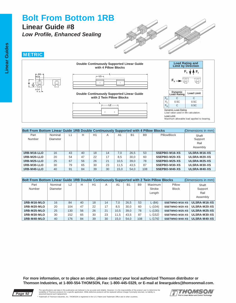
1RB-M16-MLO 16 84 40 18 14 7,0 26,5 53 L-(84) SSETWNO-M16-XS ULSRA-M16-XS1RB-M20-MLO 20 104 47 22 17 8,5 30,0 60 L-(104) SSETWNO-M20-XS ULSRA-M20-XS1RB-M25-MLO 25 130 56 26 21 10,5 39,0 78 L-(130) SSETWNO-M25-XS ULSRA-M25-XS1RB-M30-MLO 30 152 65 30 23 11,5 43,5 87 L-(152) SSETWNO-M30-XS ULSRA-M30-XS1RB-M40-MLO 40 176 84 39 30 15,0 54,0 108 L-(176) SSETWNO-M40-XS ULSRA-M40-XS
1RB-M16-LLO 16 43 40 18 14 7,0 26,5 53 SSEPBO-M16-XS ULSRA-M16-XS1RB-M20-LLO 20 54 47 22 17 8,5 30,0 60 SSEPBO-M20-XS ULSRA-M20-XS1RB-M25-LLO 25 67 56 26 21 10,5 39,0 78 SSEPBO-M25-XS ULSRA-M25-XS1RB-M30-LLO 30 79 65 30 23 11,5 43,5 87 SSEPBO-M30-XS ULSRA-M30-XS1RB-M40-LLO 40 91 84 39 30 15,0 54,0 108 SSEPBO-M40-XS ULSRA-M40-XS
Page 92The specifications and data in this publication are believed to be accurate and reliable. However, it is the responsibility of the product user to determine thesuitability of Thomson products for a specific application. While defective products will be replaced without charge if promptly returned, no liability is assumed beyond such replacement.
* Trademark of Thomson Industries, Inc. THOMSON is registered in the U.S. Patent and Trademark Office and in other countries.
Line
ar G
uid
es
For more information, or to place an order, please contact your local authorized Thomson distributor orThomson Industries, at 1-800-554-THOMSON, Fax: 1-800-445-0329, or E-mail at [email protected].
Bolt From Bottom 1RBLinear Guide #8Low Profile, Enhanced Sealing
L2
L1
L
LB9
H
B1
A A1
H1
Double Continuously Supported Linear Guide with 4 Pillow Blocks
Double Continuously Supported Linear Guide with 2 Twin Pillow Blocks
Bolt From Bottom Linear Guide 1RB Double Continuously Supported with 4 Pillow Blocks (Dimensions in mm)Part Nominal L1 H H1 A A1 B1 B9 PillowBlock Shaft
Number Diameter SupportRail
Assembly
Bolt From Bottom Linear Guide 1RB Double Continuously Supported with 2 Twin Pillow Blocks (Dimensions in mm)Part Nominal L2 H H1 A A1 B1 B9 Maximum Pillow Shaft
Number Diameter Stroke Block SupportLength Rail
Assembly
METRIC
FcFtFs
C0.5C
C
C0.5C0.5C
DynamicLoad Rating Load Limit
Load Rating andLimit by Direction
Fc Ft
Fs
Dynamic Load RatingLoad value used in life calculation.Load LimitMaximum allowable load applied to bearing.
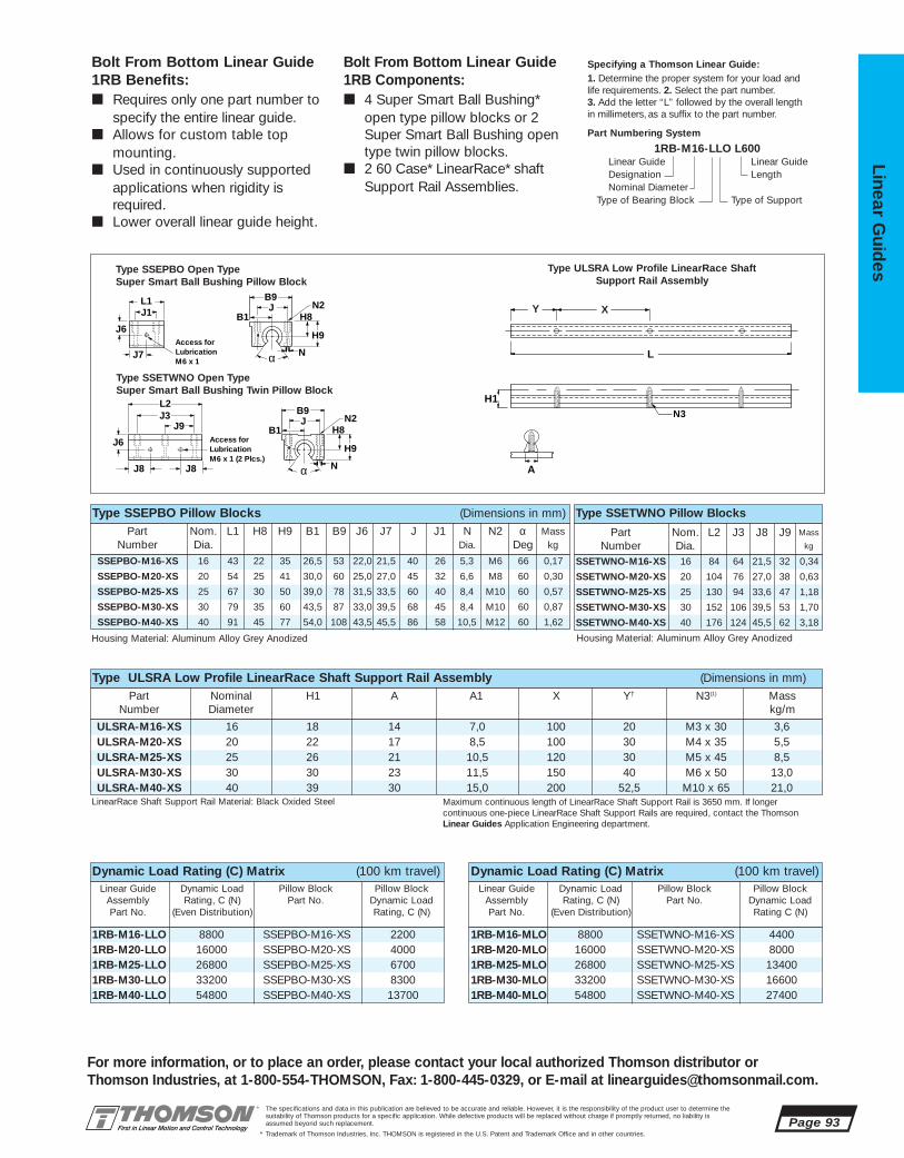
1RB-M16-LLO 8800 SSEPBO-M16-XS 22001RB-M20-LLO 16000 SSEPBO-M20-XS 40001RB-M25-LLO 26800 SSEPBO-M25-XS 67001RB-M30-LLO 33200 SSEPBO-M30-XS 83001RB-M40-LLO 54800 SSEPBO-M40-XS 13700
1RB-M16-MLO 8800 SSETWNO-M16-XS 44001RB-M20-MLO 16000 SSETWNO-M20-XS 80001RB-M25-MLO 26800 SSETWNO-M25-XS 134001RB-M30-MLO 33200 SSETWNO-M30-XS 166001RB-M40-MLO 54800 SSETWNO-M40-XS 27400
ULSRA-M16-XS 16 18 14 7,0 100 20 M3 x 30 3,6ULSRA-M20-XS 20 22 17 8,5 100 30 M4 x 35 5,5ULSRA-M25-XS 25 26 21 10,5 120 30 M5 x 45 8,5ULSRA-M30-XS 30 30 23 11,5 150 40 M6 x 50 13,0ULSRA-M40-XS 40 39 30 15,0 200 52,5 M10 x 65 21,0
SSETWNO-M16-XS 16 84 64 21,5 32 0,34
SSETWNO-M20-XS 20 104 76 27,0 38 0,63
SSETWNO-M25-XS 25 130 94 33,6 47 1,18
SSETWNO-M30-XS 30 152 106 39,5 53 1,70
SSETWNO-M40-XS 40 176 124 45,5 62 3,18
SSEPBO-M16-XS 16 43 22 35 26,5 53 22,0 21,5 40 26 5,3 M6 66 0,17
SSEPBO-M20-XS 20 54 25 41 30,0 60 25,0 27,0 45 32 6,6 M8 60 0,30
SSEPBO-M25-XS 25 67 30 50 39,0 78 31,5 33,5 60 40 8,4 M10 60 0,57
SSEPBO-M30-XS 30 79 35 60 43,5 87 33,0 39,5 68 45 8,4 M10 60 0,87
SSEPBO-M40-XS 40 91 45 77 54,0 108 43,5 45,5 86 58 10,5 M12 60 1,62
The specifications and data in this publication are believed to be accurate and reliable. However, it is the responsibility of the product user to determine thesuitability of Thomson products for a specific application. While defective products will be replaced without charge if promptly returned, no liability is assumed beyond such replacement.
* Trademark of Thomson Industries, Inc. THOMSON is registered in the U.S. Patent and Trademark Office and in other countries.
Linear Guid
es
Page 93
For more information, or to place an order, please contact your local authorized Thomson distributor orThomson Industries, at 1-800-554-THOMSON, Fax: 1-800-445-0329, or E-mail at [email protected].
J3J9
B9J
B1
L1
L2
N
J1N2
B9J
B1
N
H9
H8
H9
H8
α
α
N2
J7
J6Access forLubricationM6 x 1
J8
J8
J6
Access forLubricationM6 x 1 (2 Plcs.)
Bolt From Bottom Linear Guide 1RB Benefits:■ Requires only one part number to
specify the entire linear guide.■ Allows for custom table top
mounting.■ Used in continuously supported
applications when rigidity isrequired.
■ Lower overall linear guide height.
Bolt From Bottom Linear Guide 1RB Components:■ 4 Super Smart Ball Bushing*
open type pillow blocks or 2 Super Smart Ball Bushing open type twin pillow blocks.
■ 2 60 Case* LinearRace* shaftSupport Rail Assemblies.
Specifying a Thomson Linear Guide:1. Determine the proper system for your load and life requirements. 2. Select the part number. 3. Add the letter “L” followed by the overall lengthin millimeters, as a suffix to the part number.
Part Numbering System
1RB-M16-LLO L600Linear Guide Linear GuideDesignation LengthNominal Diameter
Type of Bearing Block Type of Support
Y X
L
H1
A
N3
Type SSEPBO Open Type Super Smart Ball Bushing Pillow Block
Type ULSRA Low Profile LinearRace Shaft Support Rail Assembly
Type SSETWNO Open Type Super Smart Ball Bushing Twin Pillow Block
Part Nom. L1 H8 H9 B1 B9 J6 J7 J J1 N N2 α MassNumber Dia. Dia. Deg kg
Type SSETWNO Pillow BlocksType SSEPBO Pillow Blocks (Dimensions in mm)
Housing Material: Aluminum Alloy Grey Anodized Housing Material: Aluminum Alloy Grey Anodized
Part Nom. L2 J3 J8 J9 Mass
Number Dia. kg
Part Nominal H1 A A1 X Y† N3(1) MassNumber Diameter kg/m
Type ULSRA Low Profile LinearRace Shaft Support Rail Assembly (Dimensions in mm)
LinearRace Shaft Support Rail Material: Black Oxided Steel Maximum continuous length of LinearRace Shaft Support Rail is 3650 mm. If longercontinuous one-piece LinearRace Shaft Support Rails are required, contact the ThomsonLinear Guides Application Engineering department.
Dynamic Load Rating (C) Matrix (100 km travel)Linear Guide Dynamic Load Pillow Block Pillow Block
Assembly Rating, C (N) Part No. Dynamic Load Part No. (Even Distribution) Rating, C (N)
Dynamic Load Rating (C) Matrix (100 km travel)Linear Guide Dynamic Load Pillow Block Pillow Block
Assembly Rating, C (N) Part No. Dynamic Load Part No. (Even Distribution) Rating C (N)

1RC-M16-MLE 8800 SSETWNO-M16-XS 44001RC-M20-MLE 16000 SSETWNO-M20-XS 80001RC-M25-MLE 26800 SSETWNO-M25-XS 134001RC-M30-MLE 33200 SSETWNO-M30-XS 166001RC-M40-MLE 54800 SSETWNO-M40-XS 27400
1RC-M16-LLF 8800 SSEPBO-M16-XS 22001RC-M20-LLF 16000 SSEPBO-M20-XS 40001RC-M25-LLF 26800 SSEPBO-M25-XS 67001RC-M30-LLF 33200 SSEPBO-M30-XS 83001RC-M40-LLF 54800 SSEPBO-M40-XS 13700
1RC-M16-MLE 16 84 125 53 18 14 7,0 86 70 L-(84) SSETWNO-M16-XS ULSRA-M16-XS1RC-M20-MLE 20 104 175 63 22 17 8,5 132 110 L-(104) SSETWNO-M20-XS ULSRA-M20-XS1RC-M25-MLE 25 130 225 76 26 21 10,5 168 140 L-(130) SSETWNO-M25-XS ULSRA-M25-XS1RC-M30-MLE 30 152 275 85 30 23 11,5 211 180 L-(152) SSETWNO-M30-XS ULSRA-M30-XS1RC-M40-MLE 40 176 325 109 39 30 15,0 247 210 L-(176) SSETWNO-M40-XS ULSRA-M40-XS
1RC-M16-LLF 16 125 125 53 18 14 7,0 86 70 L-(125) SSEPBO-M16-XS ULSRA-M16-XS1RC-M20-LLF 20 175 175 63 22 17 8,5 132 110 L-(175) SSEPBO-M20-XS ULSRA-M20-XS1RC-M25-LLF 25 225 225 76 26 21 10,5 168 140 L-(225) SSEPBO-M25-XS ULSRA-M25-XS1RC-M30-LLF 30 275 275 85 30 23 11,5 211 180 L-(275) SSEPBO-M30-XS ULSRA-M30-XS1RC-M40-LLF 40 325 325 109 39 30 15,0 247 210 L-(325) SSEPBO-M40-XS ULSRA-M40-XS
Page 94The specifications and data in this publication are believed to be accurate and reliable. However, it is the responsibility of the product user to determine thesuitability of Thomson products for a specific application. While defective products will be replaced without charge if promptly returned, no liability is assumed beyond such replacement.
* Trademark of Thomson Industries, Inc. THOMSON is registered in the U.S. Patent and Trademark Office and in other countries.
Line
ar G
uid
es
For more information, or to place an order, please contact your local authorized Thomson distributor orThomson Industries, at 1-800-554-THOMSON, Fax: 1-800-445-0329, or E-mail at [email protected].
Bolt From Bottom 1RCLinear Guide #8with Table TopLow Profile, Enhanced Sealing
T2
T1
L
LT
B
H
B2
A A1
H1
Bolt From Bottom Linear Guide 1RC Double Continuously Supported with 4 Pillow Blocks and Table Top (Size F) (Dimensions in mm)
Part Nom. T1 T H H1 A A1 B B2 Maximum Pillow ShaftNumber Dia. Stroke Block Support
Length RailAssembly
Bolt From Bottom Linear Guide 1RC Double Continuously Supported with 2 Twin Pillow Blocks and Table Top (Size E) (Dimensions in mm)
Part Nom. T2 T H H1 A A1 B B2 Maximum Pillow ShaftNumber Dia. Stroke Block Support
Length RailAssembly
Double Continuously Supported Linear Guide with 4 Pillow Blocks and Size F Table Top
Double Continuously Supported Linear Guide with 2 Twin Pillow Blocks and Size E Table Top
METRIC
Dynamic Load Rating (C) Matrix (100 km travel)Linear Guide Dynamic Load Pillow Block Pillow Block
Assembly Rating, C (N) Part No. Dynamic Load Part No. (Even Distribution) Rating, C (N)
Dynamic Load Rating (C) Matrix (100 km travel)Linear Guide Dynamic Load Pillow Block Pillow Block
Assembly Rating, C (N) Part No. Dynamic Load Part No. (Even Distribution) Rating, C (N)
FcFtFs
C0.5C
C
C0.5C0.5C
DynamicLoad Rating Load Limit
Load Rating andLimit by Direction
Fc Ft
Fs
Dynamic Load RatingLoad value used in life calculation.Load LimitMaximum allowable load applied to bearing.

1RC-M16 125 70 40 13 M6 125 26 10,0 7,5 70 84 64 10 7,5 32 451RC-M20 175 110 45 16 M8 175 32 11,0 10,0 110 104 76 14 10,0 38 551RC-M25 225 140 60 20 M8 225 40 13,5 12,5 140 130 94 18 12,5 47 651RC-M30 275 180 68 20 M8 275 45 17,0 13,5 180 152 106 23 13,5 53 751RC-M40 325 210 86 25 M10 325 58 16,5 14,5 210 176 124 26 14,5 62 85
ULSRA-M16-XS 16 18 14 7,0 100 20 M3 x 30 3,6ULSRA-M20-XS 20 22 17 8,5 100 30 M4 x 35 5,5ULSRA-M25-XS 25 26 21 10,5 120 30 M5 x 45 8,5ULSRA-M30-XS 30 30 23 11,5 150 40 M6 x 50 13,0ULSRA-M40-XS 40 39 30 15,0 200 52,5 M10 x 65 21,0
SSETWNO-M16-XS 16 84 64 21,5 32 0,34
SSETWNO-M20-XS 20 104 76 27,0 38 0,63
SSETWNO-M25-XS 25 130 94 33,6 47 1,18
SSETWNO-M30-XS 30 152 106 39,5 53 1,70
SSETWNO-M40-XS 40 176 124 45,5 62 3,18
SSEPBO-M16-XS 16 43 22 35 26,5 53 22,0 21,5 40 26 5,3 M6 66 0,17
SSEPBO-M20-XS 20 54 25 41 30,0 60 25,0 27,0 45 32 6,6 M8 60 0,30
SSEPBO-M25-XS 25 67 30 50 39,0 78 31,5 33,5 60 40 8,4 M10 60 0,57
SSEPBO-M30-XS 30 79 35 60 43,5 87 33,0 39,5 68 45 8,4 M10 60 0,87
SSEPBO-M40-XS 40 91 45 77 54,0 108 43,5 45,5 86 58 10,5 M12 60 1,62
The specifications and data in this publication are believed to be accurate and reliable. However, it is the responsibility of the product user to determine thesuitability of Thomson products for a specific application. While defective products will be replaced without charge if promptly returned, no liability is assumed beyond such replacement.
* Trademark of Thomson Industries, Inc. THOMSON is registered in the U.S. Patent and Trademark Office and in other countries.
Linear Guid
es
Page 95
For more information, or to place an order, please contact your local authorized Thomson distributor orThomson Industries, at 1-800-554-THOMSON, Fax: 1-800-445-0329, or E-mail at [email protected].
Type ULSRA Low Profile LinearRace Shaft Support Rail Assembly
Type SSEPBO Open Type Super Smart Ball Bushing Pillow Block
J3J9
B9J
B1
L1
L2
N
J1N2
B9J
B1
N
H9
H8
H9
H8
α
α
N2
J7
J6Access forLubricationM6 x 1
J8
J8
J6
Access forLubricationM6 x 1 (2 Plcs.)
Bolt From Bottom Linear Guide 1RC Components:■ 4 Super Smart Ball Bushing* open type
pillow blocks or 2 Super Smart BallBushing open type twin pillow blocks.
■ 2 60 Case* LinearRace* shaft SupportRail Assemblies.
■ 1 mounting table top with work piece and Ball Screw Assembly attachmentholes.
Bolt From Bottom Linear Guide 1RC Benefits:■ Requires only one part number to specify the
entire linear guide.■ Includes table top with standard tapped
holes for quick and easy mounting of thework piece.
■ Includes Ball Screw Assembly attachmentholes for ease of assembly and actuation.
■ Used in continuously supported applica-tions when rigidity is required.
System All Table Tops Table Top Size F Table Top Size ET M J H6 F5(2) T1 J1 J4 J5 M1 T2 J3 J4 J5 J9 M2
Mounting Table Top (Dimensions in mm)
Specifying a Thomson Linear Guide:1. Determine the proper system for your load andlife requirements. 2. Select the part number. 3. Add the letter “L” followed by the overall lengthin millimeters, as a suffix to the part number.
Part Numbering System
1RC-M16-MLE L600Linear Guide Linear GuideDesignation LengthNominal Diameter Type of Table Top
Type of Bearing Block Type of Support
Y
L
H1
A
N3
J
J5
H6
M
M1, M2 T1, T2
J3
J9J1
F5
T
J4
Material: Aluminum Alloy Grey Anodized(2) Customer Mounting Hole
Type SSETWN Open Type Super Smart Ball Bushing Twin Pillow Block
Mounting Table Top
Part Nom. L1 H8 H9 B1 B9 J6 J7 J J1 N N2 α MassNumber Dia. Dia. Deg kg
Type SSETWNO Pillow BlocksType SSEPBO Pillow Blocks (Dimensions in mm)
Housing Material: Aluminum Alloy Grey Anodized Housing Material: Aluminum Alloy Grey Anodized
Part Nom. L2 J3 J8 J9 Mass
Number Dia. kg
Part Nominal H1 A A1 X Y† N3(1) MassNumber Diameter kg/m
Type ULSRA Low Profile LinearRace Shaft Support Rail Assembly (Dimensions in mm)
LinearRace Shaft Support Rail Material: Black Oxided Steel Maximum continuous length of LinearRace Shaft Support Rail is 3650 mm. If longer continuousone-piece LinearRace Shaft Support Rails are required, contact the Thomson Linear GuidesApplication Engineering department.
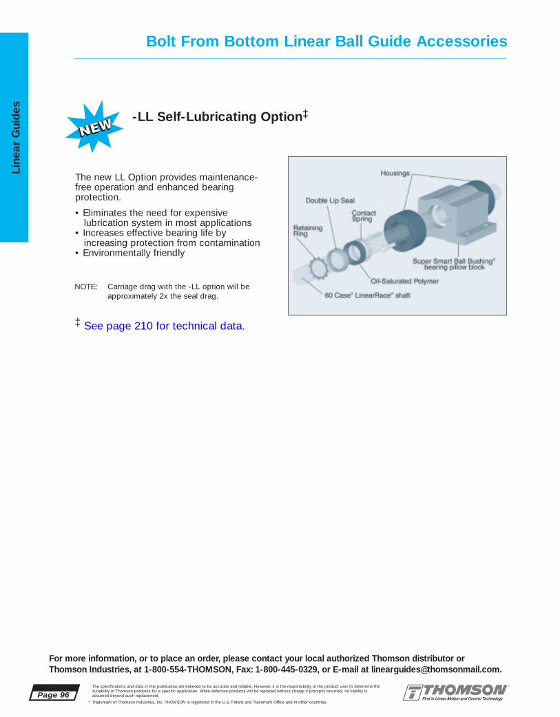
Page 96The specifications and data in this publication are believed to be accurate and reliable. However, it is the responsibility of the product user to determine thesuitability of Thomson products for a specific application. While defective products will be replaced without charge if promptly returned, no liability is assumed beyond such replacement.
* Trademark of Thomson Industries, Inc. THOMSON is registered in the U.S. Patent and Trademark Office and in other countries.
Line
ar G
uid
es -LL Self-Lubricating Option‡
The new LL Option provides maintenance-free operation and enhanced bearing protection.
• Eliminates the need for expensivelubrication system in most applications
• Increases effective bearing life byincreasing protection from contamination
• Environmentally friendly
NOTE: Carriage drag with the -LL option will beapproximately 2x the seal drag.
Bolt From Bottom Linear Ball Guide Accessories
For more information, or to place an order, please contact your local authorized Thomson distributor orThomson Industries, at 1-800-554-THOMSON, Fax: 1-800-445-0329, or E-mail at [email protected].
‡ See page 210 for technical data.
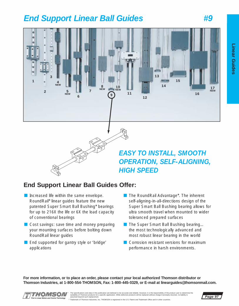
The specifications and data in this publication are believed to be accurate and reliable. However, it is the responsibility of the product user to determine thesuitability of Thomson products for a specific application. While defective products will be replaced without charge if promptly returned, no liability is assumed beyond such replacement.
* Trademark of Thomson Industries, Inc. THOMSON is registered in the U.S. Patent and Trademark Office and in other countries.
Linear Guid
es
Page 97
3
2
1 4NEW
5NEW
6
79 11
12
13
1415
16
8NEW
10NEW 17
NEW
For more information, or to place an order, please contact your local authorized Thomson distributor orThomson Industries, at 1-800-554-THOMSON, Fax: 1-800-445-0329, or E-mail at [email protected].
End Support Linear Ball Guides #9
EASY TO INSTALL, SMOOTH OPERATION, SELF-ALIGNING, HIGH SPEED
End Support Linear Ball Guides Offer:
■ Increased life within the same envelope.RoundRail* linear guides feature the new patented Super Smart Ball Bushing* bearingsfor up to 216X the life or 6X the load capacityof conventional bearings
■ Cost savings: save time and money preparingyour mounting surfaces before bolting downRoundRail linear guides
■ End supported for gantry style or ‘bridge’ applications
■ The RoundRail Advantage*. The inherent self-aligning-in-all-directions design of theSuper Smart Ball Bushing bearing allows for ultra smooth travel when mounted to wider toleranced prepared surfaces
■ The Super Smart Ball Bushing bearing…the most technologically advanced and most robust linear bearing in the world
■ Corrosion resistant versions for maximum performance in harsh environments.

1AA-04-BOO .250 2.50 .437 .81 1.63 TWN-4-XS1AA-06-BOO .375 2.75 .500 .94 1.75 TWN-6-XS1AA-08-BOO .500 3.50 .687 1.25 2.00 SSUTWN-8-XS1AA-12-BOO .750 4.50 .937 1.75 2.75 SSUTWN-12-XS1AA-16-BOO 1.000 6.00 1.187 2.19 3.25 SSUTWN-16-XS1AA-20-BOO 1.250 7.50 1.500 2.81 4.00 SSUTWN-20-XS1AA-24-BOO 1.500 9.00 1.750 3.25 4.75 SSUTWN-24-XS
1AA-04-AOO .250 1.19 .437 .81 1.63 SPB-4-XS1AA-06-AOO .375 1.31 .500 .94 1.75 SPB-6-XS1AA-08-AOO .500 1.69 .687 1.25 2.00 SSUPB-8-XS1AA-12-AOO .750 2.06 .937 1.75 2.75 SSUPB-12-XS1AA-16-AOO 1.000 2.81 1.187 2.19 3.25 SSUPB-16-XS1AA-20-AOO 1.250 3.63 1.500 2.81 4.00 SSUPB-20-XS1AA-24-AOO 1.500 4.00 1.750 3.25 4.75 SSUPB-24-XS
Page 98The specifications and data in this publication are believed to be accurate and reliable. However, it is the responsibility of the product user to determine thesuitability of Thomson products for a specific application. While defective products will be replaced without charge if promptly returned, no liability is assumed beyond such replacement.
* Trademark of Thomson Industries, Inc. THOMSON is registered in the U.S. Patent and Trademark Office and in other countries.
Line
ar G
uid
es
For more information, or to place an order, please contact your local authorized Thomson distributor orThomson Industries, at 1-800-554-THOMSON, Fax: 1-800-445-0329, or E-mail at [email protected].
End Support 1AALinear Guide #9Unsupported, Industry Standard Dimension
L2
L1
B9
H8 H9
L
L
B9
H8 H9
Single Unsupported Linear Guidewith 2 Pillow Blocks
Single Unsupported Linear Guidewith 1 Twin Pillow Block
End Support Linear Guide 1AA Single with 2 Pillow Blocks (Dimensions in inches)Part Nominal L1 H8 H9 B9 Pillow
Number Diameter Block
End Support Linear Guide 1AA Single with 1 Twin Pillow Block (Dimensions in inches)Part Nominal L2 H8 H9 B9 Pillow
Number Diameter Block
INCH
Shaft Deflection Note:Load limit may be below the dynamic load rating due to shaft deflection. Bearings can accommodate up to 1/2º deflection. See Engineering Section (pg 204) for Deflection calculations.

1AA-04-AOO 100 SPB-4-XS 501AA-06-AOO 160 SPB-6-XS 801AA-08-AOO 800 SSUPB-8-XS 4001AA-12-AOO 1800 SSUPB-12-XS 9001AA-16-AOO 3000 SSUPB-16-XS 15001AA-20-AOO 3730 SSUPB-20-XS 18651AA-24-AOO 6160 SSUPB-24-XS 3080
1AA-04-BOO 100 TWN-4-XS 100
1AA-06-BOO 160 TWN-6-XS 1601AA-08-BOO 800 SSUTWN-8-XS 8001AA-12-BOO 1800 SSUTWN-12-XS 18001AA-16-BOO 3020 SSUTWN-16-XS 30201AA-20-BOO 3730 SSUTWN-20-XS 37301AA-24-BOO 6160 SSUTWN-24-XS 6160
The specifications and data in this publication are believed to be accurate and reliable. However, it is the responsibility of the product user to determine thesuitability of Thomson products for a specific application. While defective products will be replaced without charge if promptly returned, no liability is assumed beyond such replacement.
* Trademark of Thomson Industries, Inc. THOMSON is registered in the U.S. Patent and Trademark Office and in other countries.
Linear Guid
es
Page 99
For more information, or to place an order, please contact your local authorized Thomson distributor orThomson Industries, at 1-800-554-THOMSON, Fax: 1-800-445-0329, or E-mail at [email protected].
View A-A
Specifying this Thomson Linear Guide:1. Determine the proper Linear Guide for your loadand life requirements. 2. Select the part number. 3. Add the letter “L” followed by the overall length ininches, as a suffix to the part number.
Part Numbering System
1AA-12-AOO L24Linear Guide Linear GuideDesignation LengthNominal Diameter
Type of Bearing Block
End Support Linear Guide 1AA Benefits:■ Requires only one part number to
specify entire linear guide.■ Design flexibility with custom end
supports.■ Used in end supported applications
when spanning or bridging a gap.
End Support Linear Guide 1AA Components: †
■ 2 Super Smart Ball Bushing* pillowblocks or 1 Super Smart Ball Bushing twin pillow block.
■ 1 60 Case* LinearRace* shaft.
B9
A-A
J3
H8 H5H9
B9
B7
H8 H9
L1
L2
J1
J
J
H5
B7
F
F
Access forLubrication
Access forLubrication
†
‡
Type SSUPB Super Smart Ball Bushing Pillow BlockType SPB Super Ball Bushing Pillow Block
Type SSUTWN Super Smart Ball Bushing Twin Pillow BlockType TWN Super Ball Bushing Twin Pillow Block
J
J1
‡ Sizes .250, .375 and .500 have oil lubricant fitting. Sizes .625 and above have 1/4-28 access for lubrication.
Type SPB Super Ball BushingPillow BlockMounting Hole Position forSizes .250 and .375
Dynamic Load Capacity Matrix (4 million inches travel)Linear Guide Dynamic Load Pillow Block Pillow Block
Assembly Capacity (lbf) Part No. Dynamic LoadPart No. (Even Distribution) Capacity (lbf)
SPB-4-XS .250 1.19 .81 .437 .19 1.63 1.00 1.31 .75(2) #6 .16 .10
SSUPB-8-XS .500 1.69 1.25 .687 .25 2.00 1.38 1.69 1.00 #6 .16 .20
SSUPB-16-XS 1.000 2.81 2.19 1.187 .38 3.25 2.38 2.88 1.75 #10 .22 1.24
SSUPB-24-XS 1.500 4.00 3.25 1.750 .50 4.75 3.50 4.12 2.50 1/4 .28 3.94
Type SPB and SSUPB Pillow Blocks (Dimensions in inches)
Part Nom. L2 J3 Wt.Number Dia. lb
TWN-4-XS .250 2.50 2.00 .19TWN-6-XS .375 2.75 2.25 .25
SSUTWN-8-XS .500 3.50 2.50 .40SSUTWN-12-XS .750 4.50 3.50 1.24SSUTWN-16-XS 1.000 6.00 4.50 2.48SSUTWN-20-XS 1.250 7.50 5.50 5.14SSUTWN-24-XS 1.500 9.00 6.50 8.08
Housing Material: Aluminum Alloy Black Anodized(2)Two mounting holes as shown in view A-A for sizes .250 and .375
Housing Material: Aluminum Alloy BlackAnodized
SPB-6-XS .375 1.31 .94 .500 .19 1.75 1.12 1.44 .88(2) #6 .16 .13
SSUPB-12-XS .750 2.06 1.75 .937 .31 2.75 1.88 2.38 1.25 #8 .19 .62
SSUPB-20-XS 1.250 3.63 2.81 1.500 .43 4.00 3.00 3.50 2.00 #10 .22 2.57
Type TWN and SSUTWN Pillow Blocks
Part Nom. L1 H9 H8 H5 B9 B7 J J1 F Wt.Number Dia. Bolt Hole lb
† Super Ball Bushing* bearings are used in .250and .375 inch size pillow blocks.

1AB-04-BOO .250 2.50 .437 .81 1.63 TWN-4-XS1AB-06-BOO .375 2.75 .500 .94 1.75 TWN-6-XS1AB-08-BOO .500 3.50 .687 1.25 2.00 SSUTWN-8-XS1AB-12-BOO .750 4.50 .937 1.75 2.75 SSUTWN-12-XS1AB-16-BOO 1.000 6.00 1.187 2.19 3.25 SSUTWN-16-XS1AB-20-BOO 1.250 7.50 1.500 2.81 4.00 SSUTWN-20-XS1AB-24-BOO 1.500 9.00 1.750 3.25 4.75 SSUTWN-24-XS
1AB-04-AOO .250 1.19 .437 .81 1.63 SPB-4-XS1AB-06-AOO .375 1.31 .500 .94 1.75 SPB-6-XS1AB-08-AOO .500 1.69 .687 1.25 2.00 SSUPB-8-XS1AB-12-AOO .750 2.06 .937 1.75 2.75 SSUPB-12-XS1AB-16-AOO 1.000 2.81 1.187 2.19 3.25 SSUPB-16-XS1AB-20-AOO 1.250 3.63 1.500 2.81 4.00 SSUPB-20-XS1AB-24-AOO 1.500 4.00 1.750 3.25 4.75 SSUPB-24-XS
Page 100The specifications and data in this publication are believed to be accurate and reliable. However, it is the responsibility of the product user to determine thesuitability of Thomson products for a specific application. While defective products will be replaced without charge if promptly returned, no liability is assumed beyond such replacement.
* Trademark of Thomson Industries, Inc. THOMSON is registered in the U.S. Patent and Trademark Office and in other countries.
Line
ar G
uid
es
For more information, or to place an order, please contact your local authorized Thomson distributor orThomson Industries, at 1-800-554-THOMSON, Fax: 1-800-445-0329, or E-mail at [email protected].
End Support 1ABLinear Guide #9Unsupported, Industry Standard Dimension
L2
L1
L
LB9
H8 H9
B9
H8 H9
Double Unsupported Linear Guide with 4 Pillow Blocks
Double Unsupported Linear Guide with 2 Twin Pillow Blocks
End Support Linear Guide 1AB Double with 4 Pillow Blocks (Dimensions in inches)Part Nominal L1 H8 H9 B9 Pillow
Number Diameter Block
End Support Linear Guide 1AB Double with 2 TWIN Pillow Blocks (Dimensions in inches)Part Nominal L2 H8 H9 B9 Pillow
Number Diameter Block
INCH
Shaft Deflection Note:Load limit may be below the dynamic load rating due to shaft deflection. Bearings can accommodate up to 1/2º deflection. See Engineering Section (pg 204) for Deflection calculations.

SPB-4-XS
SSUPB-8-XS
SSUPB-16-XS
SSUPB-24-XS
1AB-04-AOO 200 SPB-4-XS 501AB-06-AOO 320 SPB-6-XS 801AB-08-AOO 1600 SSUPB-8-XS 4001AB-12-AOO 2600 SSUPB-12-XS 9001AB-16-AOO 6000 SSUPB-16-XS 15001AB-20-AOO 7460 SSUPB-20-XS 18651AB-24-AOO 12320 SSUPB-24-XS 3080
1AB-04-BOO 200 TWN-4-XS 100
1AB-06-BOO 320 TWN-6-XS 1601AB-08-BOO 1600 SSUTWN-8-XS 8001AB-12-BOO 3600 SSUTWN-12-XS 18001AB-16-BOO 6040 SSUTWN-16-XS 30201AB-20-BOO 7460 SSUTWN-20-XS 37301AB-24-BOO 12320 SSUTWN-24-XS 6160
TWN-4-XS .250 2.50 2.00 .19
SSUTWN-8-XS .500 3.50 2.50 .40
SSUTWN-16-XS 1.000 6.00 4.50 2.48
SSUTWN-24-XS 1.500 9.00 6.50 8.08
.250 1.19 .81 .437 .19 1.63 1.00 1.31 .75(2) #6 .10
.500 1.69 1.25 .687 .25 2.00 1.38 1.69 1.00 #6 .16 .20
1.000 2.81 2.19 1.187 .38 3.25 2.38 2.88 1.75 #10 .22 1.24
1.500 4.00 3.25 1.750 .50 4.75 3.50 4.12 2.50 1/4 .28 3.94
The specifications and data in this publication are believed to be accurate and reliable. However, it is the responsibility of the product user to determine thesuitability of Thomson products for a specific application. While defective products will be replaced without charge if promptly returned, no liability is assumed beyond such replacement.
* Trademark of Thomson Industries, Inc. THOMSON is registered in the U.S. Patent and Trademark Office and in other countries.
Linear Guid
es
Page 101
For more information, or to place an order, please contact your local authorized Thomson distributor orThomson Industries, at 1-800-554-THOMSON, Fax: 1-800-445-0329, or E-mail at [email protected].
End Support Linear Guide 1AB Benefits:■ Allows for custom table mounting.■ Design flexibility for custom end
supports.■ Double LinearRace* shaft
configuration resists torque.■ Used in end supported
applications when spanning or bridging a gap.
End Support Linear Guide 1AB Components: †
■ 4 Super Smart Ball Bushing* pillow blocks or 2 Super Smart BallBushing twin pillow blocks.
■ 2 60 Case* LinearRace shafts.
Specifying a Thomson Linear guide:1. Determine the proper system for your load and liferequirements. 2. Select the part number. 3. Add theletter “L” followed by the overall length in inches, asa suffix to the part number.
Part Numbering System
1AB-12-AOO L24Linear Guide Linear GuideDesignation LengthNominal Diameter
Type of Bearing Block
Type SPB Super Ball BushingPillow BlockMounting Hole Position forSizes .250 and .375
View A-A
B9
A-A
J3
H8 H5H9
B9
B7
H8 H9
L1
L2
J1
J
J
H5
B7
F
F
Access forLubrication
Access forLubrication
†
‡
Type SSUPB Super Smart Ball Bushing PillowBlock Type SPB Super Ball Bushing Pillow Block
Type SSUTWN Super Smart Ball Bushing TwinPillow BlockType TWN Super Ball Bushing Twin Pillow Block J
J1
‡ Sizes .250, .375 and .500 have oil lubricant fitting.Sizes .625 and above have 1/4-28 access for lubrication.
Type SPB and SSUPB Pillow Blocks (Dimensions in inches)
Part Nom. L2 J3 Wt.Number Dia. lb
TWN-6-XS .375 2.75 2.25 .25
SSUTWN-12-XS .750 4.50 3.50 1.24
SSUTWN-20-XS 1.250 7.50 5.50 5.14
Housing Material: Aluminum Alloy Black Anodized(2)Two mounting holes as shown in view A-A for sizes .250 and .375
Part Nom. L1 H9 H8 H5 B9 B7 J J1 F Wt.Number Dia. Bolt Hole lb
.16SPB-6-XS .375 1.31 .94 .500 .19 1.75 1.12 1.44 .88(2) #6 .16 .13
SSUPB-12-XS .750 2.06 1.75 .937 .31 2.75 1.88 2.38 1.25 #8 .19 .62
SSUPB-20-XS 1.250 3.63 2.81 1.500 .43 4.00 3.00 3.50 2.00 #10 .22 2.57
Type TWN and SSUTWN Pillow Blocks
Housing Material: Aluminum Alloy BlackAnodized
Dynamic Load Capacity Matrix (4 million inches travel)Linear Guide Dynamic Load Pillow Block Pillow Block
Assembly Capacity (lbf) Part No. Dynamic LoadPart No. (Even Distribution) Capacity (lbf)
† Super Ball Bushing* bearings are used in .250and .375 inch size pillow blocks.

1AC-04-BOA .250 1.06 2.25 .437 .81 4.00 2.50 TWN-4-XS1AC-06-BOA .375 1.19 2.50 .500 .94 4.50 2.75 TWN-6-XS1AC-08-BOA .500 1.63 3.25 .687 1.25 5.50 3.50 SSUTWN-8-XS1AC-12-BOA .750 2.25 4.50 .937 1.75 7.50 4.50 SSUTWN-12-XS1AC-16-BOA 1.000 2.69 5.50 1.187 2.19 9.00 6.00 SSUTWN-16-XS1AC-20-BOA 1.250 3.56 6.75 1.500 2.81 11.00 7.50 SSUTWN-20-XS1AC-24-BOA 1.500 4.00 8.00 1.750 3.25 13.00 9.00 SSUTWN-24-XS
1AC-04-AOB .250 1.19 1.06 2.25 .437 .81 4.00 4.00 SPB-4-XS1AC-06-AOB .375 1.31 1.19 2.50 .500 .94 4.50 4.50 SPB-6-XS1AC-08-AOB .500 1.69 1.63 3.25 .687 1.25 5.50 5.50 SSUPB-8-XS1AC-12-AOB .750 2.06 2.25 4.50 .937 1.75 7.50 7.50 SSUPB-12-XS1AC-16-AOB 1.000 2.81 2.69 5.50 1.187 2.19 9.00 9.00 SSUPB-16-XS1AC-20-AOB 1.250 3.63 3.56 6.75 1.500 2.81 11.00 11.00 SSUPB-20-XS1AC-24-AOB 1.500 4.00 4.00 8.00 1.750 3.25 13.00 13.00 SSUPB-24-XS
Page 102The specifications and data in this publication are believed to be accurate and reliable. However, it is the responsibility of the product user to determine thesuitability of Thomson products for a specific application. While defective products will be replaced without charge if promptly returned, no liability is assumed beyond such replacement.
* Trademark of Thomson Industries, Inc. THOMSON is registered in the U.S. Patent and Trademark Office and in other countries.
Line
ar G
uid
es
For more information, or to place an order, please contact your local authorized Thomson distributor orThomson Industries, at 1-800-554-THOMSON, Fax: 1-800-445-0329, or E-mail at [email protected].
End Support 1ACLinear Guide #9with Table TopUnsupported, Industry Standard Dimension
B2
L1
T2
L
L
T
H8 H9
T T1
H8 H9
H
B2
H
End Support Linear Guide 1AC Double with 4 Pillow Blocks and Table Top (Size B) (Dimensions in inches)
End Support Linear Guide 1AC Double with 2 Twin Pillow Blocks and Table Top (Size A) (Dimensions in inches)
Part Nom. H B2 H8 H9 T T2 PillowNumber Dia. Block
Double Unsupported Linear Guide with 4 Pillow Blocksand Size B Table Top
Double Unsupported Linear Guide with 2 Twin PillowBlocks and Size A Table Top
Part Nom. L1 H B2 H8 H9 T T1 PillowNumber Dia. Block
INCH
Shaft Deflection Note:Load limit may be below the dynamic load rating due to shaft deflection. Bearings can accommodate up to 1/2º deflection. See Engineering Section (pg 204) for Deflection calculations.

TWN-4-XS
SSUTWN-8-XS
SSUTWN-16-XS
SSUTWN-24-XSSSUPB-24-XS 1.500 4.00 3.25 1.750 .50 4.75 3.50 4.12 2.50 1/4 .28 3.94
1AC-04-AOB 200 SPB-4-XS 501AC-06-AOB 320 SPB-6-XS 801AC-08-AOB 1600 SSUPB-8-XS 4001AC-12-AOB 3600 SSUPB-12-XS 9001AC-16-AOB 6000 SSUPB-16-XS 15001AC-20-AOB 7460 SSUPB-20-XS 18651AC-24-AOB 12320 SSUPB-24-XS 3080
.250 4.0 2.25 1.31 .250 #8-32 4.0 .75(2) .22 .22 3.50 2.50 2.00 .25 .22 2.0
.375 4.5 2.50 1.44 .250 #10-32 4.5 .88(2) .22 .28 3.75 2.75 2.25 .25 .28 2.0
.500 5.5 3.25 1.69 .375 1/4-20 5.5 1.00 .34 .28 4.50 3.50 2.50 .50 .31 2.5
.750 7.5 4.50 2.38 .500 5/16-18 7.5 1.25 .41 .31 6.00 4.50 3.50 .50 .31 3.01.000 9.0 5.50 2.88 .500 3/8-16 9.0 1.75 .53 .31 7.00 6.00 4.50 .75 .31 4.01.250 11.0 6.75 3.50 .750 1/2-13 11.0 2.00 .82 .38 8.50 7.50 5.50 1.00 .38 5.01.500 13.0 8.00 4.12 .750 1/2-13 13.0 2.50 .75 .44 10.00 9.00 6.50 1.25 .44 6.0
1AC-04-BOA 200 TWN-4-XS 1001AC-06-BOA 320 TWN-6-XS 1601AC-08-BOA 1600 SSUTWN-8-XS 8001AC-12-BOA 3600 SSUTWN-12-XS 18001AC-16-BOA 6040 SSUTWN-16-XS 30201AC-20-BOA 7460 SSUTWN-20-XS 37301AC-24-BOA 12320 SSUTWN-24-XS 6160
The specifications and data in this publication are believed to be accurate and reliable. However, it is the responsibility of the product user to determine thesuitability of Thomson products for a specific application. While defective products will be replaced without charge if promptly returned, no liability is assumed beyond such replacement.
* Trademark of Thomson Industries, Inc. THOMSON is registered in the U.S. Patent and Trademark Office and in other countries.
Linear Guid
es
Page 103
For more information, or to place an order, please contact your local authorized Thomson distributor orThomson Industries, at 1-800-554-THOMSON, Fax: 1-800-445-0329, or E-mail at [email protected].
View A-A
End Support Linear Guide 1AC Benefits:■ Includes table top with standard
tapped holes for quick and easymounting of the work piece.
■ Includes Ball Screw Assembly attachment holes for ease of assembly and actuation.
■ Used in end supported applicationswhen spanning or bridging a gap.
End Support Linear Guide 1AC Components: †
■ 4 Super Smart Ball Bushing* pillow blocks or 2 Super Smart BallBushing twin pillow blocks.
■ 2 60 Case* LinearRace* shafts.■ 1 mounting table top with work piece
and Ball Screw Assembly attachmentholes.
Specifying a Thomson Linear Guide:1. Determine the proper system for your load and liferequirements. 2. Select the part number. 3. Add theletter “L” followed by the overall length in inches, asa suffix to the part number.
Part Numbering System
1AC-12-AOO L24Linear Guide Linear GuideDesignation LengthNominal Diameter Type of Table Top
Type of Bearing Block
B9
A-A
H8 H5H9
B7
L1 J1 J
FAccess forLubrication†
J3B9
H8 H9
L2 J
H5
B7 FAccess for
Lubrication‡
J
J5
H6
M
N, N1 T1, T2
J3J1
F5
T
J4
J
J1
Type SPB Super Ball BushingPillow BlockMounting Hole Position forSizes .250 and .375
Type SSUPB Super Smart Ball Bushing Pillow Block Type SPB Super Ball Bushing Pillow Block
Type SSUTWN Super Smart Ball Bushing TwinPillow BlockType TWN Super Ball Bushing Twin Pillow Block
Mounting Table Top
‡ Sizes .250, .375 and .500 have oil lubricant fitting. Sizes, .625 and above have 1/4-28 access for lubrication.
Type SPB and SSUPB Pillow Blocks (Dimensions in inches)
Part Nom. L2 J3 Wt.Number Dia. lb
.250 2.50 2.00 .19TWN-6-XS .375 2.75 2.25 .25
.500 3.50 2.50 .40SSUTWN-12-XS .750 4.50 3.50 1.24
1.000 6.00 4.50 2.48SSUTWN-20-XS 1.250 7.50 5.50 5.14
1.500 9.00 6.50 8.08Housing Material: Aluminum Alloy Black Anodized(2)Two mounting holes as shown in view A-A for sizes .250 and .375
Housing Material: Aluminum Alloy BlackAnodized
SPB-4-XS .250 1.19 .81 .437 .19 1.63 1.00 1.31 .75(2) #6 .16 .10SPB-6-XS .375 1.31 .94 .500 .19 1.75 1.12 1.44 .88(2) #6 .16 .13
SSUPB-8-XS .500 1.69 1.25 .687 .25 2.00 1.38 1.69 1.00 #6 .16 .20SSUPB-12-XS .750 2.06 1.75 .937 .31 2.75 1.88 2.38 1.25 #8 .19 .62SSUPB-16-XS 1.000 2.81 2.19 1.187 .38 3.25 2.38 2.88 1.75 #10 .22 1.24SSUPB-20-XS 1.250 3.63 2.81 1.500 .43 4.00 3.00 3.50 2.00 #10 .22 2.57
Type TWN and SSUTWN Pillow Blocks
Part Nom. L1 H9 H8 H5 B9 B7 J J1 F Wt.Number Dia. Bolt Hole lb
Carriage Material: Aluminum Alloy Black Anodized. (2)Two mounting holes as shown in view A-A for sizes .250 and .375
Mounting Table Top (Dimensions in inches)Nominal All Table Tops Table Top Size B Table Top Size ADiameter T M J H6 F5 T1 J1 J4 J5 N T2 J3 J4 J5 N1
Dynamic Load Capacity Matrix (4 million inches travel)Linear Guide Dynamic Load Pillow Block Pillow Block
Assembly Capacity (lbf) Part No. Dynamic Load Part No. (Even Distribution) Capacity (lbf)
Dynamic Load Capacity Matrix (4 million inches travel)Linear Guide Dynamic Load Pillow Block Pillow Block
Assembly Capacity (lbf) Part No. Dynamic Load Part No. (Even Distribution) Capacity (lbf)
† Super Ball Bushing* bearings are used in .250and .375 inch size pillow blocks.

1MA-M08-POO 8 62 15 28 17,5 35 SPTWN-M08-XS1MA-M12-POO 12 76 18 35 21,5 43 SSETWN-M12-XS1MA-M16-POO 16 84 22 42 26,5 53 SSETWN-M16-XS1MA-M20-POO 20 104 25 50 30,0 60 SSETWN-M20-XS1MA-M25-POO 25 130 30 60 39,0 78 SSETWN-M25-XS1MA-M30-POO 30 152 35 70 43,5 87 SSETWN-M30-XS1MA-M40-POO 40 176 45 90 54,0 108 SSETWN-M40-XS
1MA-M08-NOO 8 32 15 28 17,5 35 SPPB-M08-XS1MA-M12-NOO 12 39 18 35 21,5 43 SSEPB-M12-XS1MA-M16-NOO 16 43 22 42 26,5 53 SSEPB-M16-XS1MA-M20-NOO 20 54 25 50 30,0 60 SSEPB-M20-XS1MA-M25-NOO 25 67 30 60 39,0 78 SSEPB-M25-XS1MA-M30-NOO 30 79 35 70 43,5 87 SSEPB-M30-XS1MA-M40-NOO 40 91 45 90 54,0 108 SSEPB-M40-XS
Page 104The specifications and data in this publication are believed to be accurate and reliable. However, it is the responsibility of the product user to determine thesuitability of Thomson products for a specific application. While defective products will be replaced without charge if promptly returned, no liability is assumed beyond such replacement.
* Trademark of Thomson Industries, Inc. THOMSON is registered in the U.S. Patent and Trademark Office and in other countries.
Line
ar G
uid
es
For more information, or to place an order, please contact your local authorized Thomson distributor orThomson Industries, at 1-800-554-THOMSON, Fax: 1-800-445-0329, or E-mail at [email protected].
End Support 1MALinear Guide #9Unsupported, Industry Standard Dimension
L2
L1
B9
H8 H9
L
LB1
Single Linear Guidewith 2 Pillow Blocks
Single Linear Guidewith 1 Twin Pillow Block
End Support Linear Guide 1MA Single with 2 Pillow Blocks (Dimensions in mm)Part Nominal L1 H8 H9 B1 B9 Pillow
Number Diameter Block
End Support Linear Guide 1MA Single with 1 Twin Pillow Block (Dimensions in mm)Part Nominal L2 H8 H9 B1 B9 Pillow
Number Diameter Block
METRIC
Shaft Deflection Note:Load limit may be below the dynamic load rating due to shaft deflection. Bearings can accommodate up to 1/2º deflection. See Engineering Section (pg 204) for Deflection calculations.

1MA-M08-NOO 620 SPPB-M08-XS 3101MA-M12-NOO 1300 SSEPB-M12-XS 6501MA-M16-NOO 4400 SSEPB-M16-XS 22001MA-M20-NOO 8000 SSEPB-M20-XS 40001MA-M25-NOO 13400 SSEPB-M25-XS 67001MA-M30-NOO 16600 SSEPB-M30-XS 83001MA-M40-NOO 27400 SSEPB-M40-XS 13700
1MA-M08-POO 500 SPTWN-M08-XS 5001MA-M12-POO 1060 SSETWN-M12-XS 10601MA-M16-POO 4400 SSETWN-M16-XS 44001MA-M20-POO 8000 SSETWN-M20-XS 80001MA-M25-POO 13400 SSETWN-M25-XS 134001MA-M30-POO 16600 SSETWN-M30-XS 166001MA-M40-POO 27400 SSETWN-M40-XS 27400
SPTWN-M08-XS 8 62 50 19,5 25 0,15
SSETWN-M12-XS 12 76 56 23,0 28 0,27
SSETWN-M16-XS 16 84 64 25,0 32 0,41
SSETWN-M20-XS 20 104 76 30,5 38 0,73
SSETWN-M25-XS 25 130 94 37,0 47 1,37
SSETWN-M30-XS 30 152 106 43,0 53 2,04
SSETWN-M40-XS 40 176 124 49,0 62 3,73
SPPB-M08-XS 8 32 15 28 17,5 35 25 20 15 19,5 3,3 M4 0,07
SSEPB-M12-XS 12 39 18 35 21,5 43 32 23 18 23,0 4,3 M5 0,13
SSEPB-M16-XS 16 43 22 42 26,5 53 40 26 22 25,0 5,3 M6 0,20
SSEPB-M20-XS 20 54 25 50 30,0 60 45 32 25 30,5 6,6 M8 0,35
SSEPB-M25-XS 25 67 30 60 39,0 78 60 40 30 37 8,4 M10 0,66
SSEPB-M30-XS 30 79 35 70 43,5 87 68 45 35 43 8,4 M10 0,99
SSEPB-M40-XS 40 91 45 90 54,0 108 86 58 45 49 10,5 M12 1,83
The specifications and data in this publication are believed to be accurate and reliable. However, it is the responsibility of the product user to determine thesuitability of Thomson products for a specific application. While defective products will be replaced without charge if promptly returned, no liability is assumed beyond such replacement.
* Trademark of Thomson Industries, Inc. THOMSON is registered in the U.S. Patent and Trademark Office and in other countries.
Linear Guid
es
Page 105
For more information, or to place an order, please contact your local authorized Thomson distributor orThomson Industries, at 1-800-554-THOMSON, Fax: 1-800-445-0329, or E-mail at [email protected].
Specifying this Thomson Linear Guide:1. Determine the proper Linear Guide for your loadand life requirements. 2. Select the part number. 3. Add the letter “L” followed by the overall length in millimeters,as a suffix to the part number.
Part Numbering System
1MA-M12-NOO L600Linear Guide Linear GuideDesignation LengthNominal Diameter
Type of Bearing Block
End Support Linear Guide 1MA Benefits:■ Requires only one part number to
specify entire linear guide.■ Design flexibility with custom end
supports.■ Used in end supported applications
when spanning or bridging a gap.
End Support Linear Guide 1MA Components: †
■ 2 Super Smart Ball Bushing* pillowblocks or 1 Super Smart BallBushing twin pillow block.
■ 1 60 Case* LinearRace* shaft.
J3J9
L2
J8
J8
J6
Access forLubricationM6 x 1 (2 Plcs.)
B9J
B1
N
H8
N2
H9
B9J
B1
L1
N
H8
J1
H9
N2
J7
J6Access forLubricationM6 x 1
Type SPPB Super Plus Ball Bushing Pillow BlockType SSEPB Super Smart Ball Bushing Pillow Block
Type SPTWN Super Plus Ball Bushing Twin Pillow BlockType SSETWN Super Smart Ball Bushing Twin Pillow Block
Type SPPB and SSEPB Pillow Blocks (Dimensions in mm)Part Nom. L2 J3 J8 J9 Mass
Number Dia. kg
Housing Material: Aluminum Alloy Grey Anodized Housing Material: Aluminum Alloy Grey Anodized
Part Nom. L1 H8 H9 B1 B9 J J1 J6 J7 N N2 MassNumber Dia. Dia. kg
Type SPTWN and SSETWN Pillow Blocks
Dynamic Load Capacity Matrix (100 km travel)Linear Guide Dynamic Load Pillow Block Pillow Block
Assembly Capacity (N) Part No. Dynamic LoadPart No. (Even Distribution) Capacity (N)
† Super Plus Ball Bushing* bearings are used in 8 mmsize pillow blocks.
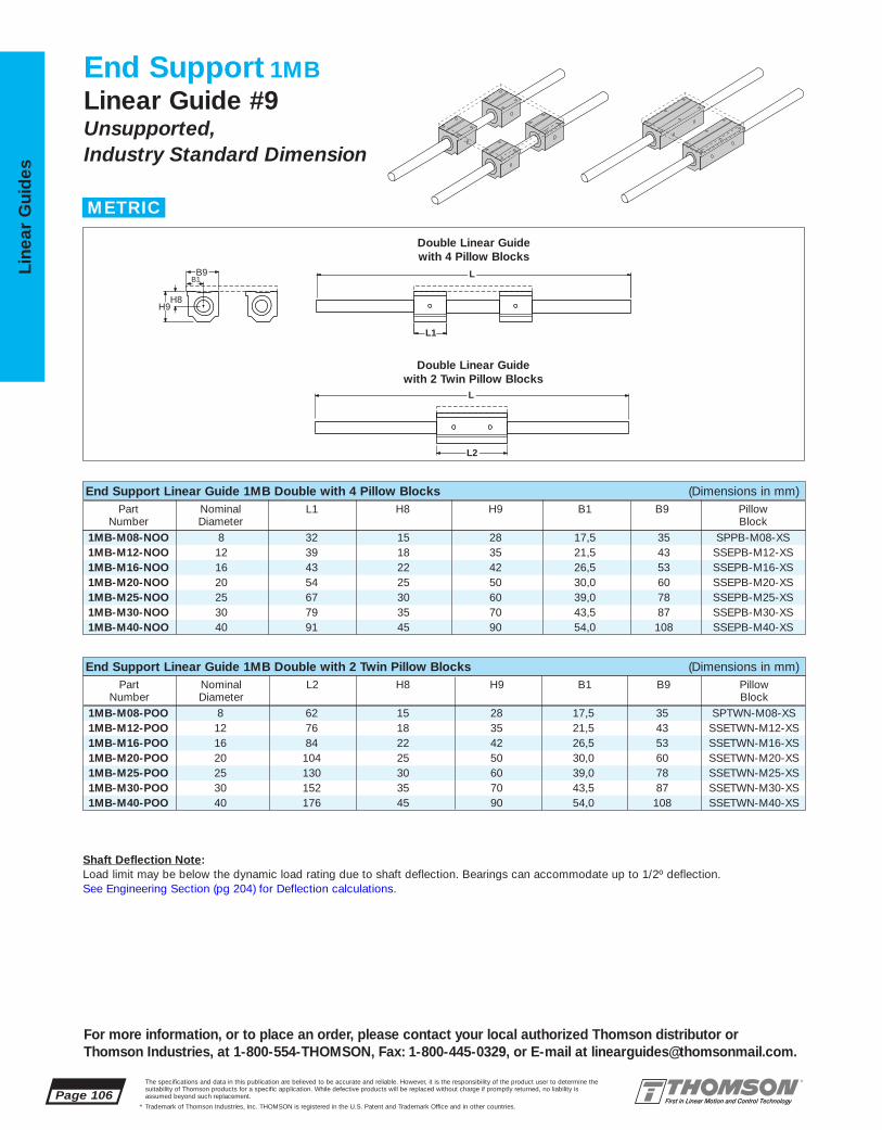
1MB-M08-POO 8 62 15 28 17,5 35 SPTWN-M08-XS1MB-M12-POO 12 76 18 35 21,5 43 SSETWN-M12-XS1MB-M16-POO 16 84 22 42 26,5 53 SSETWN-M16-XS1MB-M20-POO 20 104 25 50 30,0 60 SSETWN-M20-XS1MB-M25-POO 25 130 30 60 39,0 78 SSETWN-M25-XS1MB-M30-POO 30 152 35 70 43,5 87 SSETWN-M30-XS1MB-M40-POO 40 176 45 90 54,0 108 SSETWN-M40-XS
End Support Linear Guide 1MB Double with 2 Twin Pillow Blocks (Dimensions in mm)Part Nominal L2 H8 H9 B1 B9 Pillow
Number Diameter Block
1MB-M08-NOO 8 32 15 28 17,5 35 SPPB-M08-XS1MB-M12-NOO 12 39 18 35 21,5 43 SSEPB-M12-XS1MB-M16-NOO 16 43 22 42 26,5 53 SSEPB-M16-XS1MB-M20-NOO 20 54 25 50 30,0 60 SSEPB-M20-XS1MB-M25-NOO 25 67 30 60 39,0 78 SSEPB-M25-XS1MB-M30-NOO 30 79 35 70 43,5 87 SSEPB-M30-XS1MB-M40-NOO 40 91 45 90 54,0 108 SSEPB-M40-XS
Page 106The specifications and data in this publication are believed to be accurate and reliable. However, it is the responsibility of the product user to determine thesuitability of Thomson products for a specific application. While defective products will be replaced without charge if promptly returned, no liability is assumed beyond such replacement.
* Trademark of Thomson Industries, Inc. THOMSON is registered in the U.S. Patent and Trademark Office and in other countries.
Line
ar G
uid
es
For more information, or to place an order, please contact your local authorized Thomson distributor orThomson Industries, at 1-800-554-THOMSON, Fax: 1-800-445-0329, or E-mail at [email protected].
End Support 1MBLinear Guide #9Unsupported, Industry Standard Dimension
L2
L1
L
LB1 B9
H8 H9
Double Linear Guide with 4 Pillow Blocks
Double Linear Guide with 2 Twin Pillow Blocks
End Support Linear Guide 1MB Double with 4 Pillow Blocks (Dimensions in mm)Part Nominal L1 H8 H9 B1 B9 Pillow
Number Diameter Block
METRIC
Shaft Deflection Note:Load limit may be below the dynamic load rating due to shaft deflection. Bearings can accommodate up to 1/2º deflection. See Engineering Section (pg 204) for Deflection calculations.
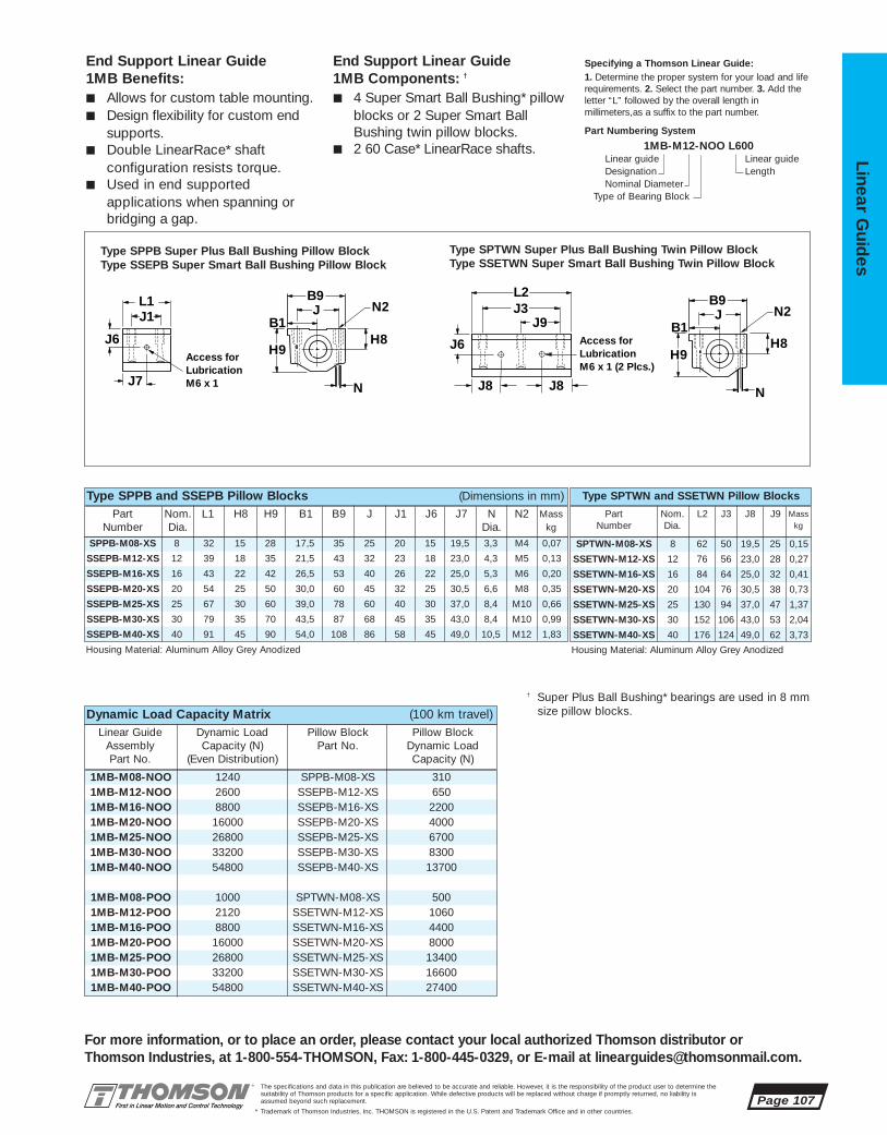
1MB-M08-NOO 1240 SPPB-M08-XS 3101MB-M12-NOO 2600 SSEPB-M12-XS 6501MB-M16-NOO 8800 SSEPB-M16-XS 22001MB-M20-NOO 16000 SSEPB-M20-XS 40001MB-M25-NOO 26800 SSEPB-M25-XS 67001MB-M30-NOO 33200 SSEPB-M30-XS 83001MB-M40-NOO 54800 SSEPB-M40-XS 13700
1MB-M08-POO 1000 SPTWN-M08-XS 5001MB-M12-POO 2120 SSETWN-M12-XS 10601MB-M16-POO 8800 SSETWN-M16-XS 44001MB-M20-POO 16000 SSETWN-M20-XS 80001MB-M25-POO 26800 SSETWN-M25-XS 134001MB-M30-POO 33200 SSETWN-M30-XS 166001MB-M40-POO 54800 SSETWN-M40-XS 27400
SPTWN-M08-XS 8 62 50 19,5 25 0,15
SSETWN-M12-XS 12 76 56 23,0 28 0,27
SSETWN-M16-XS 16 84 64 25,0 32 0,41
SSETWN-M20-XS 20 104 76 30,5 38 0,73
SSETWN-M25-XS 25 130 94 37,0 47 1,37
SSETWN-M30-XS 30 152 106 43,0 53 2,04
SSETWN-M40-XS 40 176 124 49,0 62 3,73
SPPB-M08-XS 8 32 15 28 17,5 35 25 20 15 19,5 3,3 M4 0,07
SSEPB-M12-XS 12 39 18 35 21,5 43 32 23 18 23,0 4,3 M5 0,13
SSEPB-M16-XS 16 43 22 42 26,5 53 40 26 22 25,0 5,3 M6 0,20
SSEPB-M20-XS 20 54 25 50 30,0 60 45 32 25 30,5 6,6 M8 0,35
SSEPB-M25-XS 25 67 30 60 39,0 78 60 40 30 37,0 8,4 M10 0,66
SSEPB-M30-XS 30 79 35 70 43,5 87 68 45 35 43,0 8,4 M10 0,99
SSEPB-M40-XS 40 91 45 90 54,0 108 86 58 45 49,0 10,5 M12 1,83
The specifications and data in this publication are believed to be accurate and reliable. However, it is the responsibility of the product user to determine thesuitability of Thomson products for a specific application. While defective products will be replaced without charge if promptly returned, no liability is assumed beyond such replacement.
* Trademark of Thomson Industries, Inc. THOMSON is registered in the U.S. Patent and Trademark Office and in other countries.
Linear Guid
es
Page 107
For more information, or to place an order, please contact your local authorized Thomson distributor orThomson Industries, at 1-800-554-THOMSON, Fax: 1-800-445-0329, or E-mail at [email protected].
End Support Linear Guide 1MB Benefits:■ Allows for custom table mounting.■ Design flexibility for custom end
supports.■ Double LinearRace* shaft
configuration resists torque.■ Used in end supported
applications when spanning or bridging a gap.
End Support Linear Guide 1MB Components: †
■ 4 Super Smart Ball Bushing* pillow blocks or 2 Super Smart Ball Bushing twin pillow blocks.
■ 2 60 Case* LinearRace shafts.
Specifying a Thomson Linear Guide:1. Determine the proper system for your load and liferequirements. 2. Select the part number. 3. Add the letter “L” followed by the overall length inmillimeters,as a suffix to the part number.
Part Numbering System
1MB-M12-NOO L600Linear guide Linear guideDesignation LengthNominal Diameter
Type of Bearing Block
Type SPPB and SSEPB Pillow Blocks (Dimensions in mm)Part Nom. L2 J3 J8 J9 Mass
Number Dia. kg
Housing Material: Aluminum Alloy Grey Anodized Housing Material: Aluminum Alloy Grey Anodized
Part Nom. L1 H8 H9 B1 B9 J J1 J6 J7 N N2 MassNumber Dia. Dia. kg
Type SPTWN and SSETWN Pillow Blocks
J3J9
L2
J8
J8
J6
Access forLubricationM6 x 1 (2 Plcs.)
B9J
B1
N
H8
N2
H9
B9J
B1
L1
N
H8
J1
H9
N2
J7
J6Access forLubricationM6 x 1
Type SPPB Super Plus Ball Bushing Pillow BlockType SSEPB Super Smart Ball Bushing Pillow Block
Type SPTWN Super Plus Ball Bushing Twin Pillow BlockType SSETWN Super Smart Ball Bushing Twin Pillow Block
Dynamic Load Capacity Matrix (100 km travel)Linear Guide Dynamic Load Pillow Block Pillow Block
Assembly Capacity (N) Part No. Dynamic LoadPart No. (Even Distribution) Capacity (N)
† Super Plus Ball Bushing* bearings are used in 8 mm size pillow blocks.
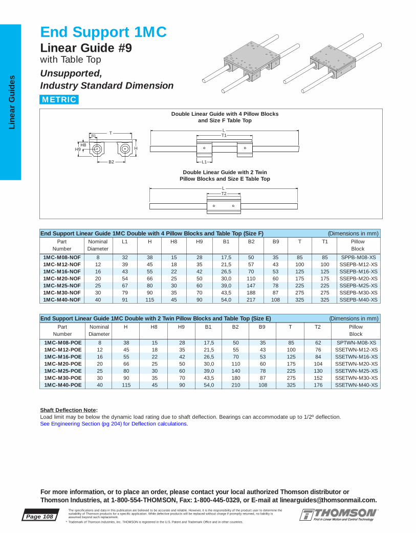
1MC-M08-POE 8 38 15 28 17,5 50 35 85 62 SPTWN-M08-XS1MC-M12-POE 12 45 18 35 21,5 55 43 100 76 SSETWN-M12-XS1MC-M16-POE 16 55 22 42 26,5 70 53 125 84 SSETWN-M16-XS1MC-M20-POE 20 66 25 50 30,0 110 60 175 104 SSETWN-M20-XS1MC-M25-POE 25 80 30 60 39,0 140 78 225 130 SSETWN-M25-XS1MC-M30-POE 30 90 35 70 43,5 180 87 275 152 SSETWN-M30-XS1MC-M40-POE 40 115 45 90 54,0 210 108 325 176 SSETWN-M40-XS
1MC-M08-NOF 8 32 38 15 28 17,5 50 35 85 85 SPPB-M08-XS1MC-M12-NOF 12 39 45 18 35 21,5 57 43 100 100 SSEPB-M12-XS1MC-M16-NOF 16 43 55 22 42 26,5 70 53 125 125 SSEPB-M16-XS1MC-M20-NOF 20 54 66 25 50 30,0 110 60 175 175 SSEPB-M20-XS1MC-M25-NOF 25 67 80 30 60 39,0 147 78 225 225 SSEPB-M25-XS1MC-M30-NOF 30 79 90 35 70 43,5 188 87 275 275 SSEPB-M30-XS1MC-M40-NOF 40 91 115 45 90 54,0 217 108 325 325 SSEPB-M40-XS
Page 108The specifications and data in this publication are believed to be accurate and reliable. However, it is the responsibility of the product user to determine thesuitability of Thomson products for a specific application. While defective products will be replaced without charge if promptly returned, no liability is assumed beyond such replacement.
* Trademark of Thomson Industries, Inc. THOMSON is registered in the U.S. Patent and Trademark Office and in other countries.
Line
ar G
uid
es
For more information, or to place an order, please contact your local authorized Thomson distributor orThomson Industries, at 1-800-554-THOMSON, Fax: 1-800-445-0329, or E-mail at [email protected].
End Support 1MCLinear Guide #9with Table TopUnsupported, Industry Standard Dimension
T2
L1
T1
L
LT
B2
HH8
H9
B1
End Support Linear Guide 1MC Double with 4 Pillow Blocks and Table Top (Size F) (Dimensions in mm)Part Nominal L1 H H8 H9 B1 B2 B9 T T1 Pillow
Number Diameter Block
End Support Linear Guide 1MC Double with 2 Twin Pillow Blocks and Table Top (Size E) (Dimensions in mm)Part Nominal H H8 H9 B1 B2 B9 T T2 Pillow
Number Diameter Block
Double Linear Guide with 4 Pillow Blocksand Size F Table Top
Double Linear Guide with 2 Twin Pillow Blocks and Size E Table Top
METRIC
Shaft Deflection Note:Load limit may be below the dynamic load rating due to shaft deflection. Bearings can accommodate up to 1/2º deflection. See Engineering Section (pg 204) for Deflection calculations.
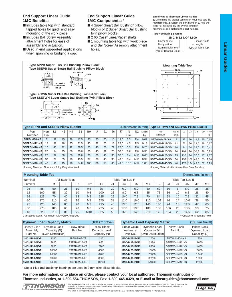
1MC-M08-POE 1000 SPTWN-M08-XS 500
1MC-M12-POE 2120 SSETWN-M12-XS 1060
1MC-M16-POE 8800 SSETWN-M16-XS 4400
1MC-M20-POE 16000 SSETWN-M20-XS 8000
1MC-M25-POE 26800 SSETWN-M25-XS 13400
1MC-M30-POE 33200 SSETWN-M30-XS 16600
1MC-M40-POE 54800 SSETWN-M40-XS 27400
1MC-M08-NOF 1240 SPPB-M08-XS 310
1MC-M12-NOF 2600 SSEPB-M12-XS 650
1MC-M16-NOF 8800 SSEPB-M16-XS 2200
1MC-M20-NOF 16000 SSEPB-M20-XS 4000
1MC-M25-NOF 26800 SSEPB-M25-XS 6700
1MC-M30-NOF 33200 SSEPB-M30-XS 8300
1MC-M40-NOF 54800 SSEPB-M40-XS 13700
08 85 50 25 10 M6 85 20 6,0 5,0 50 62 50 6 5,0 25 3512 100 55 32 10 M6 100 23 8,0 6,5 55 76 56 10 6,5 28 4016 125 70 40 13 M6 125 26 10,0 7,5 70 84 64 10 7,5 32 4520 175 110 45 16 M8 175 32 11,0 10,0 110 104 76 14 10,0 38 5525 225 140 60 20 M8 225 40 13,5 12,5 140 130 94 18 12,5 47 6530 275 180 68 20 M8 275 45 17,0 13,5 180 152 106 23 13,5 53 7540 325 210 86 25 M10 325 58 16,5 14,5 210 176 124 26 14,5 62 85
SPTWN-M08-XS 8 62 50 19,5 25 0,15
SSETWN-M12-XS 12 76 56 23,0 28 0,27
SSETWN-M16-XS 16 84 64 25,0 32 0,41
SSETWN-M20-XS 20 104 76 30,5 38 0,73
SSETWN-M25-XS 25 130 94 37,0 47 1,37
SSETWN-M30-XS 30 152 106 43,0 53 2,04
SSETWN-M40-XS 40 176 124 49,0 62 3,73
SPPB-M08-XS 8 32 15 28 17,5 35 25 20 15 19,5 3,3 M4 0,07
SSEPB-M12-XS 12 39 18 35 21,5 43 32 23 18 23,0 4,3 M5 0,13
SSEPB-M16-XS 16 43 22 42 26,5 53 40 26 22 25,0 5,3 M6 0,20
SSEPB-M20-XS 20 54 25 50 30,0 60 45 32 25 30,5 6,6 M8 0,35
SSEPB-M25-XS 25 67 30 60 39,0 78 60 40 30 37,0 8,4 M10 0,66
SSEPB-M30-XS 30 79 35 70 43,5 87 68 45 35 43,0 8,4 M10 0,99
SSEPB-M40-XS 40 91 45 90 54,0 108 86 58 45 49,0 10,5 M12 1,83
The specifications and data in this publication are believed to be accurate and reliable. However, it is the responsibility of the product user to determine thesuitability of Thomson products for a specific application. While defective products will be replaced without charge if promptly returned, no liability is assumed beyond such replacement.
* Trademark of Thomson Industries, Inc. THOMSON is registered in the U.S. Patent and Trademark Office and in other countries.
Linear Guid
es
Page 109
For more information, or to place an order, please contact your local authorized Thomson distributor orThomson Industries, at 1-800-554-THOMSON, Fax: 1-800-445-0329, or E-mail at [email protected].
End Support Linear Guide 1MC Benefits:■ Includes table top with standard
tapped holes for quick and easymounting of the work piece.
■ Includes Ball Screw Assembly attachment holes for ease of assembly and actuation.
■ Used in end supported applicationswhen spanning or bridging a gap.
End Support Linear Guide 1MC Components: †
■ 4 Super Smart Ball Bushing* pillowblocks or 2 Super Smart Ball Bushingtwin pillow blocks.
■ 2 60 Case* LinearRace* shafts.■ 1 mounting table top with work piece
and Ball Screw Assembly attachmentholes.
Specifying a Thomson Linear Guide:1. Determine the proper system for your load and liferequirements. 2. Select the part number. 3. Add the letter “L” followed by the overall length inmillimeters,as a suffix to the part number.
Part Numbering System
1MC-M12-NOF L600Linear Guide Linear GuideDesignation LengthNominal Diameter Type of Table Top
Type of Bearing Block
Carriage Material: Aluminum Alloy Grey Anodized (2) Customer Mounting hole.
Mounting Table Top (Dimensions in mm)
B9J
B1
L1
N
H8
J1
H9
N2
J7
J6Access forLubricationM6 x 1
J3J9
L2
J8
J8
J6
Access forLubricationM6 x 1 (2 Plcs.)
B9J
B1
N
H8
N2
H9
J
J5
H6
M
M1, M2 T1, T2
J3
J9J1
F5
T
J4
Type SPPB Super Plus Ball Bushing Pillow BlockType SSEPB Super Smart Ball Bushing Pillow Block
Type SPTWN Super Plus Ball Bushing Twin Pillow Block Type SSETWN Super Smart Ball Bushing Twin Pillow Block
Mounting Table Top
Nominal All Table Tops Table Top Size F Table Top Size EDiameter T M J H6 F5(2) T1 J1 J4 J5 M1 T2 J3 J4 J5 J9 M2
Type SPPB and SSEPB Pillow Blocks (Dimensions in mm)Part Nom. L2 J3 J8 J9 Mass
Number Dia. kg
Housing Material: Aluminum Alloy Grey Anodized Housing Material: Aluminum Alloy Grey Anodized
Part Nom. L1 H8 H9 B1 B9 J J1 J6 J7 N N2 MassNumber Dia. Dia. kg
Type SPTWN and SSETWN Pillow Blocks
Dynamic Load Capacity Matrix (100 km travel)Linear Guide Dynamic Load Pillow Block Pillow Block
Assembly Capacity (N) Part No. Dynamic Load Part No. (Even Distribution) Capacity (N)
Dynamic Load Capacity Matrix (100 km travel)Linear Guide Dynamic Load Pillow Block Pillow Block
Assembly Capacity (N) Part No. Dynamic Load Part No. (Even Distribution) Capacity (N)
† Super Plus Ball Bushing* bearings are used in 8 mm size pillow blocks.
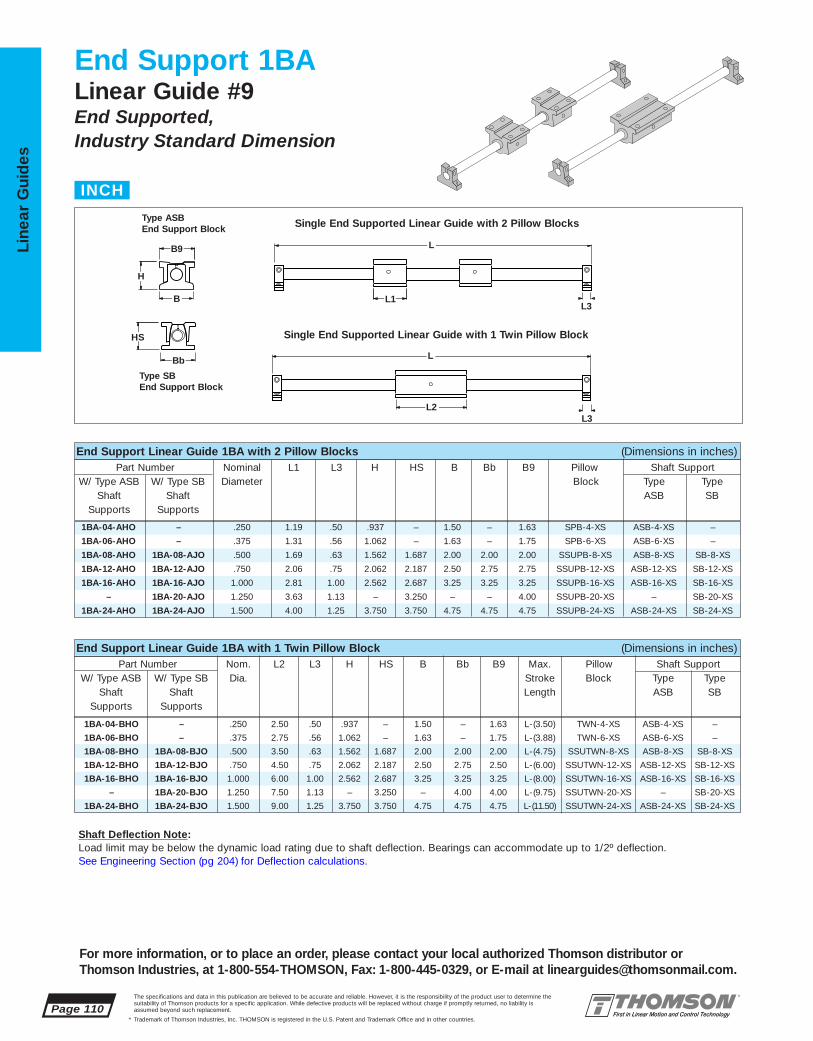
1BA-04-BHO – .250 2.50 .50 .937 – 1.50 – 1.63 L-(3.50) TWN-4-XS ASB-4-XS –
1BA-06-BHO – .375 2.75 .56 1.062 – 1.63 – 1.75 L-(3.88) TWN-6-XS ASB-6-XS –
1BA-08-BHO 1BA-08-BJO .500 3.50 .63 1.562 1.687 2.00 2.00 2.00 L-(4.75) SSUTWN-8-XS ASB-8-XS SB-8-XS
1BA-12-BHO 1BA-12-BJO .750 4.50 .75 2.062 2.187 2.50 2.75 2.50 L-(6.00) SSUTWN-12-XS ASB-12-XS SB-12-XS
1BA-16-BHO 1BA-16-BJO 1.000 6.00 1.00 2.562 2.687 3.25 3.25 3.25 L-(8.00) SSUTWN-16-XS ASB-16-XS SB-16-XS
– 1BA-20-BJO 1.250 7.50 1.13 – 3.250 – 4.00 4.00 L-(9.75) SSUTWN-20-XS – SB-20-XS
1BA-24-BHO 1BA-24-BJO 1.500 9.00 1.25 3.750 3.750 4.75 4.75 4.75 L-(11.50) SSUTWN-24-XS ASB-24-XS SB-24-XS
1BA-04-AHO – .250 1.19 .50 .937 – 1.50 – 1.63 SPB-4-XS ASB-4-XS –
1BA-06-AHO – .375 1.31 .56 1.062 – 1.63 – 1.75 SPB-6-XS ASB-6-XS –
1BA-08-AHO 1BA-08-AJO .500 1.69 .63 1.562 1.687 2.00 2.00 2.00 SSUPB-8-XS ASB-8-XS SB-8-XS
1BA-12-AHO 1BA-12-AJO .750 2.06 .75 2.062 2.187 2.50 2.75 2.75 SSUPB-12-XS ASB-12-XS SB-12-XS
1BA-16-AHO 1BA-16-AJO 1.000 2.81 1.00 2.562 2.687 3.25 3.25 3.25 SSUPB-16-XS ASB-16-XS SB-16-XS
– 1BA-20-AJO 1.250 3.63 1.13 – 3.250 – – 4.00 SSUPB-20-XS – SB-20-XS
1BA-24-AHO 1BA-24-AJO 1.500 4.00 1.25 3.750 3.750 4.75 4.75 4.75 SSUPB-24-XS ASB-24-XS SB-24-XS
Page 110The specifications and data in this publication are believed to be accurate and reliable. However, it is the responsibility of the product user to determine thesuitability of Thomson products for a specific application. While defective products will be replaced without charge if promptly returned, no liability is assumed beyond such replacement.
* Trademark of Thomson Industries, Inc. THOMSON is registered in the U.S. Patent and Trademark Office and in other countries.
Line
ar G
uid
es
End Support 1BALinear Guide #9End Supported, Industry Standard Dimension
L2
L1 L3
B9
H
L
L
B
Bb
HS
L3
End Support Linear Guide 1BA with 2 Pillow Blocks (Dimensions in inches)Part Number Nominal L1 L3 H HS B Bb B9 Pillow Shaft Support
W/ Type ASB W/ Type SB Diameter Block Type TypeShaft Shaft ASB SB
Supports Supports
End Support Linear Guide 1BA with 1 Twin Pillow Block (Dimensions in inches)Part Number Nom. L2 L3 H HS B Bb B9 Max. Pillow Shaft Support
W/ Type ASB W/ Type SB Dia. Stroke Block Type TypeShaft Shaft Length ASB SB
Supports Supports
Single End Supported Linear Guide with 2 Pillow Blocks
Single End Supported Linear Guide with 1 Twin Pillow Block
Type SBEnd Support Block
Type ASBEnd Support Block
INCH
For more information, or to place an order, please contact your local authorized Thomson distributor orThomson Industries, at 1-800-554-THOMSON, Fax: 1-800-445-0329, or E-mail at [email protected].
Shaft Deflection Note:Load limit may be below the dynamic load rating due to shaft deflection. Bearings can accommodate up to 1/2º deflection. See Engineering Section (pg 204) for Deflection calculations.

1BA-04-BHO – 100 TWN-4-XS 100
1BA-06-BHO – 160 TWN-6-XS 160
1BA-08-BHO 1BA-08-BJO 800 SSUTWN-8-XS 800
1BA-12-BHO 1BA-12-BJO 1800 SSUTWN-12-XS 1800
1BA-16-BHO 1BA-16-BJO 3000 SPSTWN-16-XS 3020
– 1BA-20-BJO 3730 SSUTWN-20-XS 1865
1BA-24-BHO 1BA-24-BJO 6160 SSUTWN-24-XS 6160
1BA-04-AHO – 100 SPB-4-XS 50
1BA-06-AHO – 160 SPB-6-XS 80
1BA-08-AHO 1BA-08-AJO 800 SSUPB-8-XS 400
1BA-12-AHO 1BA-12-AJO 1800 SSUPB-12-XS 900
1BA-16-AHO 1BA-16-AJO 3000 SPSUB-16-XS 1500
– 1BA-20-AJO 3730 SSUPB-20-XS 1865
1BA-24-AHO 1BA-24-AJO 6160 SSUPB-24-XS 3080
SB-8-XS .500 .63 1.62 1.000 2.00 1.50 #8 .19 .3SB-12-XS .750 .75 2.12 1.250 2.75 2.00 #10 .22 .5SB-16-XS 1.000 1.00 2.56 1.500 3.25 2.50 1⁄4 .28 1.0SB-20-XS 1.250 1.13 3.00 1.750 4.00 3.00 5⁄16 .34 2.0SB-24-XS 1.500 1.25 3.50 2.000 4.75 3.50 5⁄16 .34 2.6
ASB-04-XS .250 .50 .88 .500 1.50 1.12 #6 .16 .06ASB-06-XS .375 .56 1.00 .562 1.62 1.25 #6 .16 .08ASB-08-XS .500 .63 1.48 .875 2.00 1.50 #8 .19 .11ASB-12-XS .750 .75 1.95 1.125 2.50 2.00 #10 .22 .22ASB-16-XS 1.000 1.00 2.48 1.375 3.25 2.50 1⁄4 .28 .44ASB-24-XS 1.500 1.250 3.50 2.000 4.75 3.50 5⁄16 .34 1.16
TWN-4-XS .250 2.50 2.00 .19
SSUTWN-8-XS .500 3.50 2.50 .40
SSUTWN-16-XS 1.000 6.00 4.50 2.48
SSUTWN-24-XS 1.500 9.00 6.50 8.08
SPB-4-XS .250 1.19 .81 .437 .19 1.63 1.00 1.31 .75(2) #6 .16 .10
SSUPB-8-XS .500 1.69 1.25 .687 .25 2.00 1.38 1.69 1.00 #6 .16 .20
SSUPB-16-XS 1.000 2.81 2.19 1.187 .38 3.25 2.38 2.88 1.75 #10 .22 1.24
SSUPB-24-XS 1.500 4.00 3.25 1.750 .50 4.75 3.50 4.12 2.50 1⁄4 .28 3.94
The specifications and data in this publication are believed to be accurate and reliable. However, it is the responsibility of the product user to determine thesuitability of Thomson products for a specific application. While defective products will be replaced without charge if promptly returned, no liability is assumed beyond such replacement.
* Trademark of Thomson Industries, Inc. THOMSON is registered in the U.S. Patent and Trademark Office and in other countries.
Linear Guid
es
Page 111
Specifying this Thomson Linear Guide:1. Determine the proper Linear Guide for your loadand life requirements. 2. Select the part number. 3. Add the letter “L” followed by the overall length ininches, as a suffix to the part number.
Part Numbering System
1BA-12-AHO L24Linear Guide Linear GuideDesignation LengthNominal Diameter
Type of Bearing Block Type of Support
J3B9
H8 H9
L2 J
H5
B7 FAccess for
Lubrication‡
B9
A-A
H8 H5H9
B7
L1 J1 J
FAccess forLubrication†
End Support Material: Aluminum Alloy Black Anodized
Material: Iron
End Support Linear Guide 1BA Components: †
■ 2 Super Smart Ball Bushing* pillowblocks or 1 Super Smart Ball Bushingtwin pillow block.
■ 1 60 Case LinearRace shaft.■ 2 Shaft End Support Blocks.
End Support Linear Guide 1BA Benefits:■ Requires only one part number to
specify entire linear guide.■ Available with 60 Case* LinearRace*
Shaft end support blocks in eitherlight weight aluminum or rigid ironmaterials.
■ Used to provide increased stability ortorque resistance in linear systemapplications.
J
J1
Type SPB and SSUPB Pillow Blocks (Dimensions in Inches)
Part Nom. L2 J3 Wt.Number Dia. lb
TWN-6-XS .375 2.75 2.25 .25
SSUTWN-12-XS .750 4.50 3.50 1.24
SSUTWN-20-XS 1.250 7.50 5.50 5.14
Housing Material: Aluminum Alloy Black Anodized(2)Two mounting holes as shown in view A-A for sizes .250 and .375
Housing Material: Aluminum Alloy Black Anodized
Part Nom. L1 H9 H8 H5 B9 B7 J J1 F Wt.Number Dia. Bolt Hole lb
SPB-6-XS .375 1.31 .94 .500 .19 1.75 1.12 1.44 .88(2) #6 .16 .13
SSUPB-12-XS .750 2.06 1.75 .937 .31 2.75 1.88 2.38 1.25 #8 .19 .62
SSUPB-20-XS 1.250 3.63 2.81 1.500 .43 4.00 3.00 3.50 2.00 #10 .22 2.57
Type TWN and SSUTWN Pillow Blocks
Type ASB LinearRace Shaft End Support Block Type SB LinearRace Shaft End Support BlockPart Nom. L3 H3 H1 B B3 G Wt.
Number Dia. Bolt Hole lbPart Nom. L3 Hh Hc Bb B3 G Wt.
Number Dia. Bolt Hole lb
G G
Bb Bb
H3 H1 Hc Hh
B B3 B3 L3
Type SPB Super Ball BushingPillow BlockMounting Hole Position forSizes .250 and .375
Type SSUPB Super Smart Ball Bushing Pillow Block Type SPB Super Ball Bushing Pillow Block
Type ASB LinearRaceShaft End Support Block
Type SB LinearRaceShaft End Support Block
Type SSUTWN Super Smart Ball Bushing Twin Pillow BlockType TWN Super Ball Bushing Twin Pillow Block
View A-A‡ Sizes .250, .375 and .500 have oil lubricant fitting.
Sizes .625 and above have 1⁄4-28 access for lubrication.
Dynamic Load Capacity Matrix (4 million inches travel)
Linear Guide Dynamic Load Pillow Block Pillow BlockAssembly Capacity (lbf) Part No. Dynamic LoadPart No. (Even Distribution) Capacity (lbf)
Dynamic Load Capacity Matrix (4 million inches travel)
Linear Guide Dynamic Load Pillow Block Pillow BlockAssembly Capacity (lbf) Part No. Dynamic Load Part No. (Even Distribution) Capacity (lbf)
For more information, or to place an order, please contact your local authorized Thomson distributor orThomson Industries, at 1-800-554-THOMSON, Fax: 1-800-445-0329, or E-mail at [email protected].
† Super Ball Bushing* bearings are used in .250 and .375 inch size pillow blocks.

1BB-04-BHO – .250 2.50 .50 .937 – 1.50 – 1.63 L-(3.50) TWN-4-XS ASB-4-XS –
1BB-06-BHO – .375 2.75 .56 1.062 – 1.63 – 1.75 L-(3.88) TWN-6-XS ASB-6-XS –
1BB-08-BHO 1BB-08-BJO .500 3.50 .63 1.562 1.687 2.00 2.00 2.00 L-(4.75) SSUTWN-8-XS ASB-8-XS SB-8-XS
1BB-12-BHO 1BB-12-BJO .750 4.50 .75 2.062 2.187 2.50 2.75 2.50 L-(6.00) SSUTWN-12-XS ASB-12-XS SB-12-XS
1BB-16-BHO 1BB-16-BJO 1.000 6.00 1.00 2.562 2.687 3.25 3.25 3.25 L-(8.00) SSUTWN-16-XS ASB-16-XS SB-16-XS
– 1BB-20-BJO 1.250 7.50 1.13 – 3.250 – 4.00 4.00 L-(9.75) SSUTWN-20-XS – SB-20-XS
1BB-24-BHO 1BB-24-BJO 1.500 9.00 1.25 3.750 3.750 4.75 4.75 4.75 L-(11.50) SSUTWN-24-XS ASB-24-XS SB-24-XS
1BB-04-AHO – .250 1.19 .50 .937 – 1.50 – 1.63 SPB-4-XS ASB-4-XS –
1BB-06-AHO – .375 1.31 .56 1.062 – 1.63 – 1.75 SPB-6-XS ASB-6-XS –
1BB-08-AHO 1BB-08-AJO .500 1.69 .63 1.562 1.687 2.00 2.00 2.00 SSUPB-8-XS ASB-8-XS SB-8-XS
1BB-12-AHO 1BB-12-AJO .750 2.06 .75 2.062 2.187 2.50 2.75 2.75 SSUPB-12-XS ASB-12-XS SB-12-XS
1BB-16-AHO 1BB-16-AJO 1.000 2.81 1.00 2.562 2.687 3.25 3.25 3.25 SSUPB-16-XS ASB-16-XS SB-16-XS
– 1BB-20-AJO 1.250 3.63 1.13 – 3.250 – – 4.00 SSUPB-20-XS – SB-20-XS
1BB-24-AHO 1BB-24-AJO 1.500 4.00 1.25 3.750 3.750 4.75 4.75 4.75 SSUPB-24-XS ASB-24-XS SB-24-XS
Page 112The specifications and data in this publication are believed to be accurate and reliable. However, it is the responsibility of the product user to determine thesuitability of Thomson products for a specific application. While defective products will be replaced without charge if promptly returned, no liability is assumed beyond such replacement.
* Trademark of Thomson Industries, Inc. THOMSON is registered in the U.S. Patent and Trademark Office and in other countries.
Line
ar G
uid
es
For more information, or to place an order, please contact your local authorized Thomson distributor orThomson Industries, at 1-800-554-THOMSON, Fax: 1-800-445-0329, or E-mail at [email protected].
End Support 1BBLinear Guide #9End Supported, Industry Standard Dimension
Bb
HS
B9
H
B
H1
L1 L3
L
L2
L
L3
Double End Supported Linear Guide with 4 Pillow Blocks
Double End Supported Linear Guide with 2 Twin Pillow Blocks
Maximum Stroke Lengthis determined by subtractingpillow block length (L2) and2x support block length (L3)from total Linear Guidelength (L).
Type SBEnd Support Block
Type ASBEnd Support Block
End Support Linear Guide 1BB with 4 Pillow Blocks (Dimensions in inches)Part Number Nominal L1 L3 H HS B Bb B9 Pillow Shaft Support
W/ Type ASB W/ Type SB Diameter Block Type TypeShaft Shaft ASB SB
Supports Supports
End Support Linear Guide 1BB with 2 Twin Pillow Blocks (Dimensions in inches)Part Number Nom. L2 L3 H HS B Bb B9 Max. Pillow Shaft Support
W/ Type ASB W/ Type SB Dia. Stroke Block Type TypeShaft Shaft Length ASB SB
Supports Supports
INCH
Shaft Deflection Note:Load limit may be below the dynamic load rating due to shaft deflection. Bearings can accommodate up to 1/2º deflection. See Engineering Section (pg 204) for Deflection calculations.
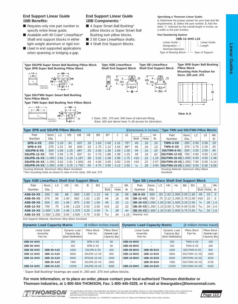
1BB-04-BHO – 200 TWN-4-XS 100
1BB-06-BHO – 320 TWN-6-XS 160
1BB-08-BHO 1BB-08-BJO 1600 SSUTWN-8-XS 800
1BB-12-BHO 1BB-12-BJO 3600 SSUTWN-12-XS 1800
1BB-16-BHO 1BB-16-BJO 6040 SPSTWN-16-XS 3020
– 1BB-20-BJO 7460 SSUTWN-20-XS 3730
1BB-24-BHO 1BB-24-BJO 12320 SSUTWN-24-XS 6160
1BB-04-AHO – 200 SPB-4-XS 50
1BB-06-AHO – 320 SPB-6-XS 80
1BB-08-AHO 1BB-08-AJO 1600 SSUPB-8-XS 400
1BB-12-AHO 1BB-12-AJO 3600 SSUPB-12-XS 900
1BB-16-AHO 1BB-16-AJO 6000 SPSUB-16-XS 1500
– 1BB-20-AJO 7460 SSUPB-20-XS 1865
1BB-24-AHO 1BB-24-AJO 12320 SSUPB-24-XS 3080
SB-8-XS .500 .63 1.62 1.000 2.00 1.50 #8 .19 .3SB-12-XS .750 .75 2.12 1.250 2.75 2.00 #10 .22 .5SB-16-XS 1.000 1.00 2.56 1.500 3.25 2.50 1⁄4 .28 1.0SB-20-XS 1.250 1.13 3.00 1.750 4.00 3.00 5⁄16 .34 2.0SB-24-XS 1.500 1.25 3.50 2.000 4.75 3.50 5⁄16 .34 2.6
ASB-04-XS .250 .50 .88 .500 1.50 1.12 #6 .16 .06ASB-06-XS .375 .56 1.00 .562 1.62 1.25 #6 .16 .08ASB-08-XS .500 .63 1.48 .875 2.00 1.50 #8 .19 .11ASB-12-XS .750 .75 1.95 1.125 2.50 2.00 #10 .22 .22ASB-16-XS 1.000 1.00 2.48 1.375 3.25 2.50 1⁄4 .28 .44ASB-24-XS 1.500 1.250 3.50 2.000 4.75 3.50 5⁄16 .34 1.16
TWN-4-XS .250 2.50 2.00 .19
SSUTWN-8-XS .500 3.50 2.50 .40
SSUTWN-16-XS 1.000 6.00 4.50 2.48
SSUTWN-24-XS 1.500 9.00 6.50 8.08
SPB-4-XS .250 1.19 .81 .437 .19 1.63 1.00 1.31 .75(2) #6 .16 .10
SSUPB-8-XS .500 1.69 1.25 .687 .25 2.00 1.38 1.69 1.00 #6 .16 .20
SSUPB-16-XS 1.000 2.81 2.19 1.187 .38 3.25 2.38 2.88 1.75 #10 .22 1.24
SSUPB-24-XS 1.500 4.00 3.25 1.750 .50 4.75 3.50 4.12 2.50 1⁄4 .28 3.94
The specifications and data in this publication are believed to be accurate and reliable. However, it is the responsibility of the product user to determine thesuitability of Thomson products for a specific application. While defective products will be replaced without charge if promptly returned, no liability is assumed beyond such replacement.
* Trademark of Thomson Industries, Inc. THOMSON is registered in the U.S. Patent and Trademark Office and in other countries.
Linear Guid
es
Page 113
For more information, or to place an order, please contact your local authorized Thomson distributor orThomson Industries, at 1-800-554-THOMSON, Fax: 1-800-445-0329, or E-mail at [email protected].
Specifying a Thomson Linear Guide:1. Determine the proper system for your load and liferequirements. 2. Select the part number. 3. Add theletter “L” followed by the overall length in inches, asa suffix to the part number.
Part Numbering System
1BB-12-AHO L24Linear Guide Linear GuideDesignation LengthNominal Diameter
Type of Bearing Block Type of Support
End Support Linear Guide 1BB Components: †
■ 4 Super Smart Ball Bushing* pillow blocks or Super Smart BallBushing twin pillow blocks.
■ 2 60 Case LinearRace shafts.■ 4 Shaft End Support Blocks.
End Support Linear Guide 1BB Benefits:■ Requires only one part number to
specify entire linear guide.■ Available with 60 Case* LinearRace*
Shaft end support blocks in eitherlight weight aluminum or rigid iron
■ Used in end supported applicationswhen spanning or bridging a gap.
End Support Material: Aluminum Alloy Black Anodized
Material: Iron
Type SPB and SSUPB Pillow Blocks (Dimensions in Inches)
Part Nom. L2 J3 Wt.Number Dia. lb
TWN-6-XS .375 2.75 2.25 .25
SSUTWN-12-XS .750 4.50 3.50 1.24
SSUTWN-20-XS 1.250 7.50 5.50 5.14
Housing Material: Aluminum Alloy Black Anodized(2)Two mounting holes as shown in view A-A for sizes .250 and .375
Housing Material: Aluminum Alloy Black Anodized
Part Nom. L1 H9 H8 H5 B9 B7 J J1 F Wt.Number Dia. Bolt Hole lb
SPB-6-XS .375 1.31 .94 .500 .19 1.75 1.12 1.44 .88(2) #6 .16 .13
SSUPB-12-XS .750 2.06 1.75 .937 .31 2.75 1.88 2.38 1.25 #8 .19 .62
SSUPB-20-XS 1.250 3.63 2.81 1.500 .43 4.00 3.00 3.50 2.00 #10 .22 2.57
Type TWN and SSUTWN Pillow Blocks
Type ASB LinearRace Shaft End Support Block Type SB LinearRace Shaft End Support BlockPart Nom. L3 H3 H1 B B3 G Wt.
Number Dia. Bolt Hole lbPart Nom. L3 Hh Hc Bb B3 G Wt.
Number Dia. Bolt Hole lb
J3B9
H8 H9
L2 J
H5
B7 FAccess for
Lubrication‡
B9
A-A
H8 H5H9
B7
L1 J1 J
FAccess forLubrication†
J
J1
G G
Bb Bb
H3 H1 Hc Hh
B B3 B3 L3
Type SPB Super Ball BushingPillow BlockMounting Hole Position forSizes .250 and .375
Type SSUPB Super Smart Ball Bushing Pillow Block Type SPB Super Ball Bushing Pillow Block
Type ASB LinearRaceShaft End Support Block
Type SB LinearRaceShaft End Support Block
Type SSUTWN Super Smart Ball Bushing Twin Pillow BlockType TWN Super Ball Bushing Twin Pillow Block
View A-A
‡ Sizes .250, .375 and .500 have oil lubricant fitting. Sizes .625 and above have 1⁄4-28 access for lubrication.
Dynamic Load Capacity Matrix (4 million inches travel)
Linear Guide Dynamic Load Pillow Block Pillow BlockAssembly Capacity (lbf) Part No. Dynamic LoadPart No. (Even Distribution) Capacity (lbf)
Dynamic Load Capacity Matrix (4 million inches travel)
Linear Guide Dynamic Load Pillow Block Pillow BlockAssembly Capacity (lbf) Part No. Dynamic LoadPart No. (Even Distribution) Capacity (lbf)
† Super Ball Bushing* bearings are used in .250 and .375 inch pillow blocks.
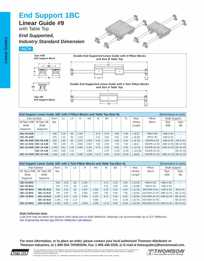
1BC-04-BHA – .250 2.50 .50 1.187 – 3.75 2.25 4.00 L-(3.50) TWN-4-XS ASB-4-XS –
1BC-06-BHA – .375 2.75 .56 1.132 – 4.13 2.50 4.50 L-(3.88) TWN-6-XS ASB-6-XS –
1BC-08-BHA 1BC-08-BJA .500 3.50 .63 1.937 2.062 5.25 3.25 5.50 L-(4.75) SSUTWN-8-XS ASB-8-XS SB-8-XS
1BC-12-BHA 1BC-12-BJA .750 4.50 .75 2.562 2.687 7.00 4.50 7.50 L-(6.00) SSUTWN-12-XS ASB-12-XS SB-12-XS
1BC-16-BHA 1BC-16-BJA 1.000 6.00 1.00 3.062 3.187 8.75 5.50 9.00 L-(8.00) SSUTWN-16-XS ASB-16-XS SB-16-XS
– 1BC-20-BJA 1.250 7.50 1.13 – 4.000 – 6.75 11.00 L-(9.75) SSUTWN-20-XS – SB-20-XS
1BC-24-BHA 1BC-24-BJA 1.500 9.00 1.25 4.500 4.500 12.75 8.00 13.00 L-(11.50) SSUTWN-24-XS ASB-24-XS SB-24-XS
1BC-04-AHB – .250 1.19 .50 1.187 – 3.75 2.25 4.00 4.00 L-(5.0) SPB-4-XS ASB-4-XS –
1BC-06-AHB – .375 1.31 .56 1.312 – 4.13 2.50 4.50 4.50 L-(5.62) SPB-6-XS ASB-6-XS –
1BC-08-AHB 1BC-08-AJB .500 1.69 .63 1.937 2.062 5.25 3.25 5.50 5.50 L-(6.76) SSUPB-8-XS ASB-8-XS SB-8-XS
1BC-12-AHB 1BC-12-AJB .750 2.06 .75 2.562 2.687 7.00 4.50 7.50 7.50 L-(9.0) SSUPB-12-XS ASB-12-XS SB-12-XS
1BC-16-AHB 1BC-16-AJB 1.000 2.81 1.00 3.062 3.187 8.75 5.50 9.00 9.00 L-(11.0) SSUPB-16-XS ASB-16-XS SB-16-XS
– 1BC-20-AJB 1.250 3.63 1.13 – 4.000 – 6.75 11.00 11.00 L-(13.26) SSUPB-20-XS – SB-20-XS
1BC-24-AHB 1BC-24-AJB 1.500 4.00 1.25 4.500 4.500 12.75 8.00 13.00 13.00 L-(15.5) SSUPB-24-XS ASB-24-XS SB-24-XS
Page 114The specifications and data in this publication are believed to be accurate and reliable. However, it is the responsibility of the product user to determine thesuitability of Thomson products for a specific application. While defective products will be replaced without charge if promptly returned, no liability is assumed beyond such replacement.
* Trademark of Thomson Industries, Inc. THOMSON is registered in the U.S. Patent and Trademark Office and in other countries.
Line
ar G
uid
es
For more information, or to place an order, please contact your local authorized Thomson distributor orThomson Industries, at 1-800-554-THOMSON, Fax: 1-800-445-0329, or E-mail at [email protected].
End Support 1BCLinear Guide #9with Table TopEnd Supported, Industry Standard Dimension
T2
T1
L1
L
L
HS
B2T
H
B L3
L3
End Support Linear Guide 1BC with 4 Pillow Blocks and Table Top (Size B) (Dimensions in inch)Part Number Nom. L1 L3 H HS B B2 T T1 Max. Pillow Shaft Support
W/Type ASB W/Type SB Dia. Stroke Block Type TypeShaft Shaft Length ASB SB
Supports Supports
End Support Linear Guide 1BC with 2 Twin Pillow Blocks and Table Top (Size A) (Dimensions in inch)Part Number Nom. T2 L3 H HS B B2 T Max. Pillow Shaft Support
W/ Type ASB W/ Type SB Dia. Stroke Block Type TypeShaft Shaft Length ASB SB
Supports Supports
Double End Supported Linear Guide with 4 Pillow Blocks and Size B Table Top
Double End Supported Linear Guide with 2 Twin Pillow Blocks and Size A Table Top
Type SBEnd Support Block
Type ASBEnd Support Block
INCH
Shaft Deflection Note:Load limit may be below the dynamic load rating due to shaft deflection. Bearings can accommodate up to 1/2º deflection. See Engineering Section (pg 204) for Deflection calculations.

.250 4.0 2.25 1.31 .250 #8-32 4.0 .75(2) .22 .22 3.50 2.50 2.00 .25 .22 2.0
.375 4.5 2.50 1.44 .250 #10-32 4.5 .88(2) .22 .28 3.75 2.75 2.25 .25 .28 2.0
.500 5.5 3.25 1.69 .375 1/4-20 5.5 1.00 .34 .28 4.50 3.50 2.50 .50 .31 2.5
.750 7.5 4.50 2.38 .500 5/16-18 7.5 1.25 .41 .31 6.00 4.50 3.50 .50 .31 3.01.000 9.0 5.50 2.88 .500 3/8-16 9.0 1.75 .53 .31 7.00 6.00 4.50 .75 .31 4.01.250 11.0 6.75 3.50 .750 1/2-13 11.0 2.00 .82 .38 8.50 7.50 5.50 1.00 .38 5.01.500 13.0 8.00 4.12 .750 1/2-13 13.0 2.50 .75 .44 10.00 9.00 6.50 1.25 .44 6.0
SB-8-XS .500 .63 1.62 1.000 2.00 1.50 #8 .19 .3SB-12-XS .750 .75 2.12 1.250 2.75 2.00 #10 .22 .5SB-16-XS 1.000 1.00 2.56 1.500 3.25 2.50 1⁄4 .28 1.0SB-20-XS 1.250 1.13 3.00 1.750 4.00 3.00 5⁄16 .34 2.0SB-24-XS 1.500 1.25 3.50 2.000 4.75 3.50 5⁄16 .34 2.6
ASB-04-XS .250 .50 .88 .500 1.50 1.12 #6 .16 .06ASB-06-XS .375 .56 1.00 .562 1.62 1.25 #6 .16 .08ASB-08-XS .500 .63 1.48 .875 2.00 1.50 #8 .19 .11ASB-12-XS .750 .75 1.95 1.125 2.50 2.00 #10 .22 .22ASB-16-XS 1.000 1.00 2.48 1.375 3.25 2.50 1⁄4 .28 .44ASB-24-XS 1.500 1.250 3.50 2.000 4.75 3.50 5⁄16 .34 1.16
TWN-4-XS .250 2.50 2.00 .19
SSUTWN-8-XS .500 3.50 2.50 .40
SSUTWN-16-XS 1.000 6.00 4.50 2.48
SSUTWN-24-XS 1.500 9.00 6.50 8.08
SPB-4-XS .250 1.19 .81 .437 .19 1.63 1.00 1.31 .75(2) #6 .16 .10
SSUPB-8-XS .500 1.69 1.25 .687 .25 2.00 1.38 1.69 1.00 #6 .16 .20
SSUPB-16-XS 1.000 2.81 2.19 1.187 .38 3.25 2.38 2.88 1.75 #10 .22 1.24
SSUPB-24-XS 1.500 4.00 3.25 1.750 .50 4.75 3.50 4.12 2.50 1⁄4 .28 3.94
Carriage Material: Aluminum Alloy Black Anodized(2)Two mounting holes as shown in view A-A for sizes .250 and .375
‡ Sizes .250, .375 and .500 have oil lubricant fitting. Sizes, .625 and above have 1/4-28access for lubrication.
The specifications and data in this publication are believed to be accurate and reliable. However, it is the responsibility of the product user to determine thesuitability of Thomson products for a specific application. While defective products will be replaced without charge if promptly returned, no liability is assumed beyond such replacement.
* Trademark of Thomson Industries, Inc. THOMSON is registered in the U.S. Patent and Trademark Office and in other countries.
Linear Guid
es
Page 115
For more information, or to place an order, please contact your local authorized Thomson distributor orThomson Industries, at 1-800-554-THOMSON, Fax: 1-800-445-0329, or E-mail at [email protected].
Specifying a Thomson Linear Guide:1. Determine the proper system for your load and liferequirements. 2. Select the part number. 3. Add theletter “L” followed by the overall length in inches, asa suffix to the part number.
Part Numbering System
1BC-12-AHB L24Linear Guide Linear GuideDesignation LengthNominal Diameter Type of Table Top
Type of Bearing Block Type of Support
J
J1
B9
A-A
J3
H8 H5H9
B9
B7
H8 H9
L1
L2
J1
J
J
H5
B7
F
F
Access forLubrication
Access forLubrication
†
‡
End Support Linear Guide 1BC Components: †
■ 4 Super Smart Ball Bushing* pillowblocks or 2 Super Smart BallBushing twin pillow blocks.
■ 2 60 Case LinearRace shafts.■ 4 Shaft End Support Blocks.■ 1 mounting table top with work piece
and Ball Screw Assembly attachmentholes.
End Support Linear Guide 1BC Benefits:■ Includes table top with standard tapped
holes for quick and easy mounting of thework piece.
■ Includes Ball Screw Assembly attachment holes for ease of assemblyand actuation.
■ Available with 60 Case* LinearRace* shaftend support blocks in either light weightaluminum or rigid iron materials.
Mounting Table Top (Dimensions in inches)
J
J5
H6
M
N, N1 T1, T2
J3J1
F5
T
J4
G
G
Bb Bb
H3 H1
Hc Hh
B
B3
B3 L3
Type SPB Super Ball BushingPillow BlockMounting Hole Position forSizes .250 and .375
Type SSUPB Super Smart Ball Bushing Pillow Block Type SPB Super Ball Bushing Pillow Block
Type ASB LinearRaceShaft End Support Block
Type SB LinearRaceShaft End Support Block
Type SSUTWN Super Smart Ball Bushing Twin Pillow BlockType TWN Super Ball Bushing Twin Pillow Block
View A-A
Mounting Table Top
End Support Material: Aluminum Alloy Black Anodized
Material: Iron
Type SPB and SSUPB Pillow Blocks (Dimensions in Inches)
Part Nom. L2 J3 Wt.Number Dia. lb
TWN-6-XS .375 2.75 2.25 .25
SSUTWN-12-XS .750 4.50 3.50 1.24
SSUTWN-20-XS 1.250 7.50 5.50 5.14
Housing Material: Aluminum Alloy Black Anodized(2)Two mounting holes as shown in view A-A for sizes .250 and .375
Housing Material: Aluminum Alloy Black Anodized
Part Nom. L1 H9 H8 H5 B9 B7 J J1 F Wt.Number Dia. Bolt Hole lb
SPB-6-XS .375 1.31 .94 .500 .19 1.75 1.12 1.44 .88(2) #6 .16 .13
SSUPB-12-XS .750 2.06 1.75 .937 .31 2.75 1.88 2.38 1.25 #8 .19 .62
SSUPB-20-XS 1.250 3.63 2.81 1.500 .43 4.00 3.00 3.50 2.00 #10 .22 2.57
Type TWN and SSUTWN Pillow Blocks
Type ASB LinearRace Shaft End Support Block Type SB LinearRace Shaft End Support BlockPart Nom. L3 H3 H1 B B3 G Wt.
Number Dia. Bolt Hole lbPart Nom. L3 Hh Hc Bb B3 G Wt.
Number Dia. Bolt Hole lb
Nominal All Table Tops Table Top Size B Table Top Size ADiameter T M J H6 F5 T1 J1 J4 J5 N T2 J3 J4 J5 N1
† Super Ball Bushing* bearings are used in .250 and .375 inchsize pillow blocks.

1NA-M08-PMO 1NA-M08-PNO 8 62 18 10 30 15 32 32 35 SPTWN-M08-XS ASB-M08-XS SB-M08-XS
1NA-M12-PMO 1NA-M12-PNO 12 76 20 12 38 20 43 42 43 SSETWN-M12-XS ASB-M12-XS SB-M12-XS
1NA-M16-PMO 1NA-M16-PNO 16 84 24 16 47 25 53 50 53 SSETWN-M16-XS ASB-M16-XS SB-M16-XS
1NA-M20-PMO 1NA-M20-PNO 20 104 30 20 55 30 60 60 60 SSETWN-M20-XS ASB-M20-XS SB-M20-XS
1NA-M25-PMO 1NA-M25-PNO 25 130 38 25 65 35 78 74 78 SSETWN-M25-XS ASB-M25-XS SB-M25-XS
1NA-M30-PMO 1NA-M30-PNO 30 152 40 28 75 40 87 84 87 SSETWN-M30-XS ASB-M30-XS SB-M30-XS
1NA-M40-PMO 1NA-M40-PNO 40 176 48 32 95 50 108 108 108 SSETWN-M40-XS ASB-M40-XS SB-M40-XS
1NA-M08-NMO 1NA-M08-NNO 8 32 18 10 30 15 32 32 35 SPPB-M08-XS ASB-M08-XS SB-M08-XS
1NA-M12-NMO 1NA-M12-NNO 12 39 20 12 38 20 43 42 43 SSEPB-M12-XS ASB-M12-XS SB-M12-XS
1NA-M16-NMO 1NA-M16-NNO 16 43 24 16 47 25 53 50 53 SSEPB-M16-XS ASB-M16-XS SB-M16-XS
1NA-M20-NMO 1NA-M20-NNO 20 54 30 20 55 30 60 60 60 SSEPB-M20-XS ASB-M20-XS SB-M20-XS
1NA-M25-NMO 1NA-M25-NNO 25 67 38 25 65 35 78 74 78 SSEPB-M25-XS ASB-M25-XS SB-M25-XS
1NA-M30-NMO 1NA-M30-NNO 30 79 40 28 75 40 87 84 87 SSEPB-M30-XS ASB-M30-XS SB-M30-XS
1NA-M40-NMO 1NA-M40-NNO 40 91 48 32 95 50 108 108 108 SSEPB-M40-XS ASB-M40-XS SB-M40-XS
Page 116The specifications and data in this publication are believed to be accurate and reliable. However, it is the responsibility of the product user to determine thesuitability of Thomson products for a specific application. While defective products will be replaced without charge if promptly returned, no liability is assumed beyond such replacement.
* Trademark of Thomson Industries, Inc. THOMSON is registered in the U.S. Patent and Trademark Office and in other countries.
Line
ar G
uid
es
For more information, or to place an order, please contact your local authorized Thomson distributor orThomson Industries, at 1-800-554-THOMSON, Fax: 1-800-445-0329, or E-mail at [email protected].
End Support 1NALinear Guide #9End Supported, Industry Standard Dimension
L2
L1
B9
H H1
L
L
B L3 B3
Bb B4
HH1
L3
L4
End Support Linear Guide 1NA with 2 Pillow Blocks (Dimensions in mm)Part Number Nom. L1 L3 L4 H H1 B Bb B9 Pillow Shaft Support
W/ Type ASB W/ Type SB Dia. Block Type TypeShaft Shaft ASB SB
Supports Supports
End Support Linear Guide 1NA with 1 Twin Pillow Block (Dimensions in mm)Part Number Nom. L2 L3 L4 H H1 B Bb B9 Pillow Shaft Support
W/ Type ASB W/ Type SB Dia. Block Type Type
Shaft Shaft ASB SBSupports Supports
Supported Linear Guide with 2 Pillow Blocks
Supported Linear Guide with 1 Twin Pillow Block Maximum Stroke Length
is determined by subtractingpillow block length (L2) and 2x support block length (L3) or (L4) from total Linear Guidelength (L).
Type SBEnd Support Block
Type ASBEnd Support Block
METRIC
Shaft Deflection Note:Load limit may be below the dynamic load rating due to shaft deflection. Bearings can accommodate up to 1/2º deflection. See Engineering Section (pg 204) for Deflection calculations.

1NA-M08-PMO 1NA-M08-PNO 500 SPTWN-M08-XS 500
1NA-M12-PMO 1NA-M12-PNO 1060 SSETWN-M12-XS 1060
1NA-M16-PMO 1NA-M16-PNO 4400 SSETWN-M16-XS 4400
1NA-M20-PMO 1NA-M20-PNO 8000 SSETWN-M20-XS 8000
1NA-M25-PMO 1NA-M25-PNO 13400 SSETWN-M25-XS 13400
1NA-M30-PMO 1NA-M30-PNO 16600 SSETWN-M30-XS 16600
1NA-M40-PMO 1NA-M40-PNO 27400 SSETWN-M40-XS 27400
Dynamic Load Capacity Matrix (100 km travel)
Linear Guide Dynamic Load Pillow Block Pillow BlockAssembly Capacity (N) Part No. Dynamic Load Part No. (Even Distribution) Capacity (N)
1NA-M08-NMO 1NA-M08-NNO 620 SPPB-M08-XS 310
1NA-M12-NMO 1NA-M12-NNO 1300 SSEPB-M12-XS 650
1NA-M16-NMO 1NA-M16-NNO 4400 SSEPB-M16-XS 2200
1NA-M20-NMO 1NA-M20-NNO 8000 SSEPB-M20-XS 4000
1NA-M25-NMO 1NA-M25-NNO 13400 SSEPB-M25-XS 6700
1NA-M30-NMO 1NA-M30-NNO 16600 SSEPB-M30-XS 8300
1NA-M40-NMO 1NA-M40-NNO 27400 SSEPB-M40-XS 13700
SB-M08-XS 8 16 25 32 15 5,2 27 10 4,5 0,03
SB-M12-XS 12 21 32 42 20 5,5 35 12 5,5 0,06
SB-M16-XS 16 25 40 50 25 6,5 42 16 5,5 0,11
SB-M20-XS 20 30 45 60 30 8,0 50 20 5,5 0,21
SB-M25-XS 25 37 60 74 35 9,0 58 25 6,6 0,35
SB-M30-XS 30 42 68 84 40 10,0 68 28 9,0 0,52
SB-M40-XS 40 54 86 108 50 12,0 86 32 11,0 0,92
ASB-M08-XS 8 16,0 32 22 15 28 18 3,5 M4 0,04
ASB-M12-XS 12 21,5 43 30 20 36 20 5,3 M6 0,10
ASB-M16-XS 16 26,5 53 38 25 43 24 6,6 M8 0,15
ASB-M20-XS 20 30,0 60 42 30 51 30 8,4 M10 0,23
ASB-M25-XS 25 39,0 78 56 35 61 38 10,5 M12 0,41
ASB-M30-XS 30 43,5 87 64 40 71 40 10,5 M12 0,53
ASB-M40-XS 40 54,0 108 82 50 88 48 13,5 M16 0,99
SPTWN-M08-XS 8 62 50 19,5 25 0,15
SSETWN-M12-XS 12 76 56 23,0 28 0,27
SSETWN-M16-XS 16 84 64 25,0 32 0,41
SSETWN-M20-XS 20 104 76 30,5 38 0,73
SSETWN-M25-XS 25 130 94 37,0 47 1,37
SSETWN-M30-XS 30 152 106 43,0 53 2,04
SSETWN-M40-XS 40 176 124 49,0 62 3,73
SPPB-M08-XS 8 32 15 28 17,5 35 25 20 15 19,5 3,3 M4 0,07
SSEPB-M12-XS 12 39 18 35 21,5 43 32 23 18 23,0 4,3 M5 0,13
SSEPB-M16-XS 16 43 22 42 26,5 53 40 26 22 25,0 5,3 M6 0,20
SSEPB-M20-XS 20 54 25 50 30,0 60 45 32 25 30,5 6,6 M8 0,35
SSEPB-M25-XS 25 67 30 60 39,0 78 60 40 30 37,0 8,4 M10 0,66
SSEPB-M30-XS 30 79 35 70 43,5 87 68 45 35 43,0 8,4 M10 0,99
SSEPB-M40-XS 40 91 45 90 54,0 108 86 58 45 49,0 10,5 M12 1,83
The specifications and data in this publication are believed to be accurate and reliable. However, it is the responsibility of the product user to determine thesuitability of Thomson products for a specific application. While defective products will be replaced without charge if promptly returned, no liability is assumed beyond such replacement.
* Trademark of Thomson Industries, Inc. THOMSON is registered in the U.S. Patent and Trademark Office and in other countries.
Linear Guid
es
Page 117
For more information, or to place an order, please contact your local authorized Thomson distributor orThomson Industries, at 1-800-554-THOMSON, Fax: 1-800-445-0329, or E-mail at [email protected].
J3J9
B9J
B1
L1
L2
N
H8
J1
H9
N2
J8 J8
J6
Access forLubricationM6 x 1 (2 Plcs.)
J7
J6Access forLubricationM6 x 1
B9J
B1
N
H8
N2
H9
End Support Material: Aluminum Alloy Grey Anodized End Support Material: Iron
End Support Linear Guide 1NA Components: †
■ 2 Super Smart Ball Bushing* pillowblocks or 1 Super Smart BallBushing twin pillow block.
■ 1 60 Case LinearRace shaft.
End Support Linear Guide 1NA Benefits:■ Requires only one part number to
specify entire linear guide.■ Available with 60 Case* LinearRace*
shaft end support blocks in either lightweight aluminum or rigid iron materials.
■ Used as a load support, transport andguidance solution.
Specifying a Thomson Linear Guide:1. Determine the proper Linear Guide for your load andlife requirements. 2. Select the part number. 3. Add theletter “L” followed by the overall length in millimeters,as a suffix to the part number.
Part Numbering System
1NA-M12-NMO L600Linear Guide Linear GuideDesignation LengthNominal Diameter
Type of Bearing Block Type of Support
Type SPPB and SSEPB Pillow Blocks (Dimensions in mm)Part Nom. L2 J3 J8 J9 Mass
Number Dia. kg
Housing Material: Aluminum Alloy Grey Anodized Housing Material: Aluminum Alloy Grey Anodized
Part Nom. L1 H8 H9 B1 B9 J J1 J6 J7 N N2 MassNumber Dia. Dia. kg
Type SPTWN and SSETWN Pillow Blocks
Type ASB LinearRace Shaft End Support Block Type SB LinearRace Shaft End Support BlockPart Nom. A1 B B3 H1 H3 L3 N3 N4 Mass
Number Dia. Dia. kg
Part Nom. A2 B4 Bb H1 H2 H4 L4 N5 Mass
Number Dia. Dia. kg
Bb B4
A2
H1H2 N5H4
L4
Type SPPB Super Plus Ball Bushing Pillow Block Type SSEPB Super Smart Ball Bushing Pillow Block
Type ASB LinearRaceShaft End Support Block
Type SB LinearRaceShaft End Support Block
Type SPTWN Super Plus Ball Bushing Twin Pillow BlockType SSETWN Super Smart Ball Bushing Twin Pillow Block
H1
B B3
A1 N4
N3
H3 H
L3
Dynamic Load Capacity Matrix (100 km travel)
Linear Guide Dynamic Load Pillow Block Pillow BlockAssembly Capacity (N) Part No. Dynamic LoadPart No. (Even Distribution) Capacity (N)
† Super Plus Ball Bushing* bearings are used in 8 mm size pillow blocks.
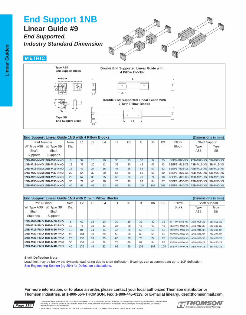
1NB-M08-PMO 1NB-M08-PNO 8 62 18 10 30 15 32 32 35 SPTWN-M08-XS ASB-M08-XS SB-M08-XS
1NB-M12-PMO 1NB-M12-PNO 12 76 20 12 38 20 43 42 43 SSETWN-M12-XS ASB-M12-XS SB-M12-XS
1NB-M16-PMO 1NB-M16-PNO 16 84 24 16 47 25 53 50 53 SSETWN-M16-XS ASB-M16-XS SB-M16-XS
1NB-M20-PMO 1NB-M20-PNO 20 104 30 20 55 30 60 60 60 SSETWN-M20-XS ASB-M20-XS SB-M20-XS
1NB-M25-PMO 1NB-M25-PNO 25 130 38 25 65 35 78 74 78 SSETWN-M25-XS ASB-M25-XS SB-M25-XS
1NB-M30-PMO 1NB-M30-PNO 30 152 40 28 75 40 87 84 87 SSETWN-M30-XS ASB-M30-XS SB-M30-XS
1NB-M40-PMO 1NB-M40-PNO 40 176 48 32 95 50 108 108 108 SSETWN-M40-XS ASB-M40-XS SB-M40-XS
1NB-M08-NMO 1NB-M08-NNO 8 32 18 10 30 15 32 32 35 SPPB-M08-XS ASB-M08-XS SB-M08-XS
1NB-M12-NMO 1NB-M12-NNO 12 39 20 12 38 20 43 42 43 SSEPB-M12-XS ASB-M12-XS SB-M12-XS
1NB-M16-NMO 1NB-M16-NNO 16 43 24 16 47 25 53 50 53 SSEPB-M16-XS ASB-M16-XS SB-M16-XS
1NB-M20-NMO 1NB-M20-NNO 20 54 30 20 55 30 60 60 60 SSEPB-M20-XS ASB-M20-XS SB-M20-XS
1NB-M25-NMO 1NB-M25-NNO 25 67 38 25 65 35 78 74 78 SSEPB-M25-XS ASB-M25-XS SB-M25-XS
1NB-M30-NMO 1NB-M30-NNO 30 79 40 28 75 40 87 84 87 SSEPB-M30-XS ASB-M30-XS SB-M30-XS
1NB-M40-NMO 1NB-M40-NNO 40 91 48 32 95 50 108 108 108 SSEPB-M40-XS ASB-M40-XS SB-M40-XS
Page 118The specifications and data in this publication are believed to be accurate and reliable. However, it is the responsibility of the product user to determine thesuitability of Thomson products for a specific application. While defective products will be replaced without charge if promptly returned, no liability is assumed beyond such replacement.
* Trademark of Thomson Industries, Inc. THOMSON is registered in the U.S. Patent and Trademark Office and in other countries.
Line
ar G
uid
es
For more information, or to place an order, please contact your local authorized Thomson distributor orThomson Industries, at 1-800-554-THOMSON, Fax: 1-800-445-0329, or E-mail at [email protected].
End Support 1NBLinear Guide #9End Supported, Industry Standard Dimension
L2
L1
L
L
L3
Bb B4
HH1
L3
B9
H H1
B B3
L4
Double End Supported Linear Guide with 4 Pillow Blocks
Double End Supported Linear Guide with 2 Twin Pillow Blocks
Type SBEnd Support Block
Type ASBEnd Support Block
End Support Linear Guide 1NB with 4 Pillow Blocks (Dimensions in mm)Part Number Nom. L1 L3 L4 H H1 B Bb B9 Pillow Shaft Support
W/ Type ASB W/ Type SB Dia. Block Type TypeShaft Shaft ASB SB
Supports Supports
End Support Linear Guide 1NB with 2 Twin Pillow Blocks (Dimensions in mm)Part Number Nom. L2 L3 L4 H H1 B Bb B9 Pillow Shaft Support
W/ Type ASB W/ Type SB Dia. Block Type TypeShaft Shaft ASB SB
Supports Supports
METRIC
Shaft Deflection Note:Load limit may be below the dynamic load rating due to shaft deflection. Bearings can accommodate up to 1/2º deflection. See Engineering Section (pg 204) for Deflection calculations.
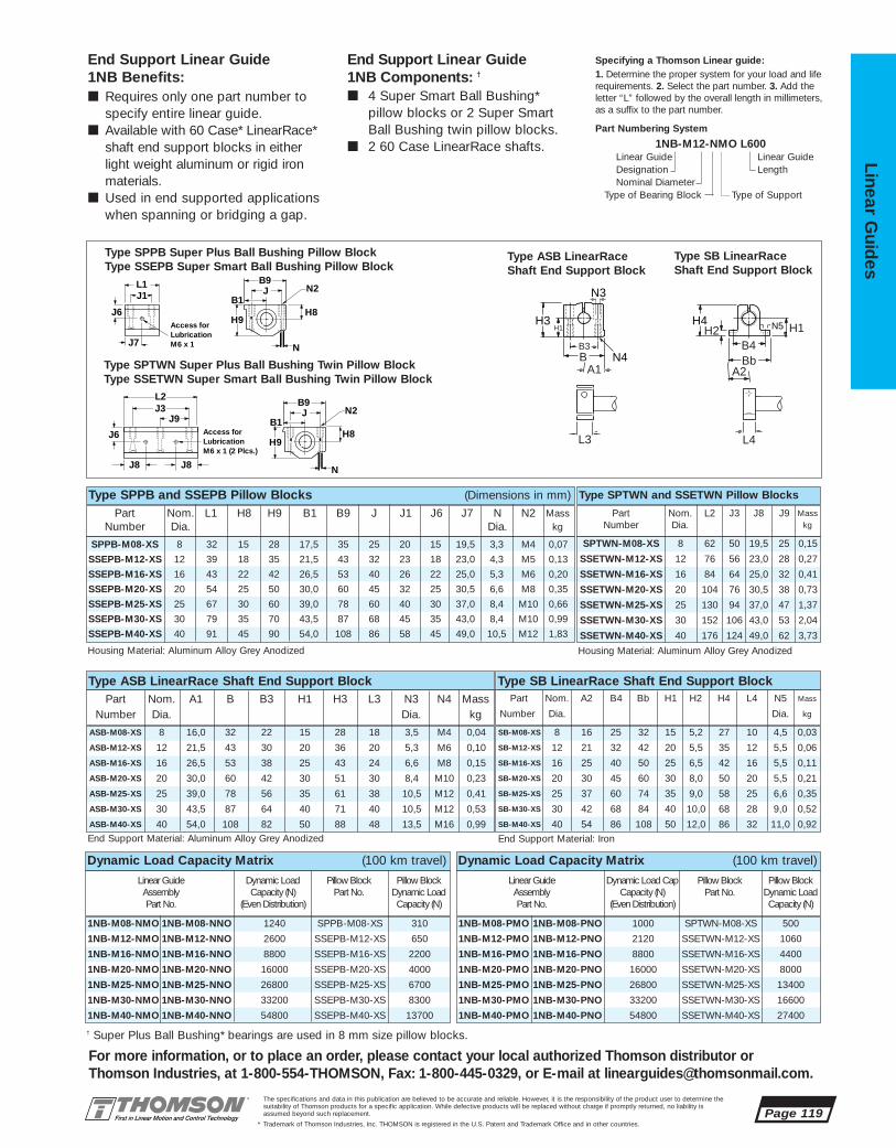
SPPB-M08-XS 8 32 15 28 17,5 35 25 20 15 19,5 3,3 M4 0,07
SSEPB-M12-XS 12 39 18 35 21,5 43 32 23 18 23,0 4,3 M5 0,13
SSEPB-M16-XS 16 43 22 42 26,5 53 40 26 22 25,0 5,3 M6 0,20
SSEPB-M20-XS 20 54 25 50 30,0 60 45 32 25 30,5 6,6 M8 0,35
SSEPB-M25-XS 25 67 30 60 39,0 78 60 40 30 37,0 8,4 M10 0,66
SSEPB-M30-XS 30 79 35 70 43,5 87 68 45 35 43,0 8,4 M10 0,99
SSEPB-M40-XS 40 91 45 90 54,0 108 86 58 45 49,0 10,5 M12 1,83
SPTWN-M08-XS 8 62 50 19,5 25 0,15
SSETWN-M12-XS 12 76 56 23,0 28 0,27
SSETWN-M16-XS 16 84 64 25,0 32 0,41
SSETWN-M20-XS 20 104 76 30,5 38 0,73
SSETWN-M25-XS 25 130 94 37,0 47 1,37
SSETWN-M30-XS 30 152 106 43,0 53 2,04
SSETWN-M40-XS 40 176 124 49,0 62 3,73
J3J9
B9J
B1
L1
L2
N
H8
J1
H9
N2
J8 J8
J6
Access forLubricationM6 x 1 (2 Plcs.)
J7
J6Access forLubricationM6 x 1
B9J
B1
N
H8
N2
H9
SB-M08-XS 8 16 25 32 15 5,2 27 10 4,5 0,03
SB-M12-XS 12 21 32 42 20 5,5 35 12 5,5 0,06
SB-M16-XS 16 25 40 50 25 6,5 42 16 5,5 0,11
SB-M20-XS 20 30 45 60 30 8,0 50 20 5,5 0,21
SB-M25-XS 25 37 60 74 35 9,0 58 25 6,6 0,35
SB-M30-XS 30 42 68 84 40 10,0 68 28 9,0 0,52
SB-M40-XS 40 54 86 108 50 12,0 86 32 11,0 0,92
ASB-M08-XS 8 16,0 32 22 15 28 18 3,5 M4 0,04
ASB-M12-XS 12 21,5 43 30 20 36 20 5,3 M6 0,10
ASB-M16-XS 16 26,5 53 38 25 43 24 6,6 M8 0,15
ASB-M20-XS 20 30,0 60 42 30 51 30 8,4 M10 0,23
ASB-M25-XS 25 39,0 78 56 35 61 38 10,5 M12 0,41
ASB-M30-XS 30 43,5 87 64 40 71 40 10,5 M12 0,53
ASB-M40-XS 40 54,0 108 82 50 88 48 13,5 M16 0,99
1NB-M08-PMO 1NB-M08-PNO 1000 SPTWN-M08-XS 500
1NB-M12-PMO 1NB-M12-PNO 2120 SSETWN-M12-XS 1060
1NB-M16-PMO 1NB-M16-PNO 8800 SSETWN-M16-XS 4400
1NB-M20-PMO 1NB-M20-PNO 16000 SSETWN-M20-XS 8000
1NB-M25-PMO 1NB-M25-PNO 26800 SSETWN-M25-XS 13400
1NB-M30-PMO 1NB-M30-PNO 33200 SSETWN-M30-XS 16600
1NB-M40-PMO 1NB-M40-PNO 54800 SSETWN-M40-XS 27400
Dynamic Load Capacity Matrix (100 km travel)
End Support Linear Guide 1NB Components: †
■ 4 Super Smart Ball Bushing* pillow blocks or 2 Super Smart Ball Bushing twin pillow blocks.
■ 2 60 Case LinearRace shafts.
End Support Linear Guide 1NB Benefits:■ Requires only one part number to
specify entire linear guide.■ Available with 60 Case* LinearRace*
shaft end support blocks in either light weight aluminum or rigid ironmaterials.
■ Used in end supported applicationswhen spanning or bridging a gap.
Specifying a Thomson Linear guide:1. Determine the proper system for your load and liferequirements. 2. Select the part number. 3. Add theletter “L” followed by the overall length in millimeters,as a suffix to the part number.
Part Numbering System
1NB-M12-NMO L600Linear Guide Linear GuideDesignation LengthNominal Diameter
Type of Bearing Block Type of Support
Bb B4
A2
H1H2 N5H4
L4
H1
B B3
A1 N4
N3
H3
L3
Type SPPB Super Plus Ball Bushing Pillow BlockType SSEPB Super Smart Ball Bushing Pillow Block
Type ASB LinearRaceShaft End Support Block
Type SB LinearRaceShaft End Support Block
Type SPTWN Super Plus Ball Bushing Twin Pillow BlockType SSETWN Super Smart Ball Bushing Twin Pillow Block
End Support Material: Aluminum Alloy Grey Anodized End Support Material: Iron
Type SPPB and SSEPB Pillow Blocks (Dimensions in mm)Part Nom. L2 J3 J8 J9 Mass
Number Dia. kg
Housing Material: Aluminum Alloy Grey Anodized Housing Material: Aluminum Alloy Grey Anodized
Part Nom. L1 H8 H9 B1 B9 J J1 J6 J7 N N2 MassNumber Dia. Dia. kg
Type SPTWN and SSETWN Pillow Blocks
Type ASB LinearRace Shaft End Support Block Type SB LinearRace Shaft End Support BlockPart Nom. A1 B B3 H1 H3 L3 N3 N4 Mass
Number Dia. Dia. kg
Part Nom. A2 B4 Bb H1 H2 H4 L4 N5 Mass
Number Dia. Dia. kg
The specifications and data in this publication are believed to be accurate and reliable. However, it is the responsibility of the product user to determine thesuitability of Thomson products for a specific application. While defective products will be replaced without charge if promptly returned, no liability is assumed beyond such replacement.
* Trademark of Thomson Industries, Inc. THOMSON is registered in the U.S. Patent and Trademark Office and in other countries.
Linear Guid
es
For more information, or to place an order, please contact your local authorized Thomson distributor orThomson Industries, at 1-800-554-THOMSON, Fax: 1-800-445-0329, or E-mail at [email protected].
1NB-M08-NMO 1NB-M08-NNO 1240 SPPB-M08-XS 310
1NB-M12-NMO 1NB-M12-NNO 2600 SSEPB-M12-XS 650
1NB-M16-NMO 1NB-M16-NNO 8800 SSEPB-M16-XS 2200
1NB-M20-NMO 1NB-M20-NNO 16000 SSEPB-M20-XS 4000
1NB-M25-NMO 1NB-M25-NNO 26800 SSEPB-M25-XS 6700
1NB-M30-NMO 1NB-M30-NNO 33200 SSEPB-M30-XS 8300
1NB-M40-NMO 1NB-M40-NNO 54800 SSEPB-M40-XS 13700
Dynamic Load Capacity Matrix (100 km travel)
Linear Guide Dynamic Load Pillow Block Pillow BlockAssembly Capacity (N) Part No. Dynamic Load Part No. (Even Distribution) Capacity (N)
Linear Guide Dynamic Load Cap Pillow Block Pillow BlockAssembly Capacity (N) Part No. Dynamic Load Part No. (Even Distribution) Capacity (N)
† Super Plus Ball Bushing* bearings are used in 8 mm size pillow blocks.
Page 119

1NC-M08-PME 1NC-M08-PNE 8 18 10 40 15 32 32 50 35 85 62 SPTWN-M08-XS ASB-M0B8-XS SB-M08-XS
1NC-M12-PME 1NC-M12-PNE 12 20 12 48 20 43 43 55 43 100 76 SSETWN-M12-XS ASB-M12-XS SB-M12-XS
1NC-M16-PME 1NC-M16-PNE 16 24 16 60 25 53 53 70 53 125 84 SSETWN-M16-XS ASB-M16-XS SB-M16-XS
1NC-M20-PME 1NC-M20-PNE 20 30 20 71 30 60 60 110 60 175 104 SSETWN-M20-XS ASB-M20-XS SB-M20-XS
1NC-M25-PME 1NC-M25-PNE 25 38 25 85 35 78 74 140 78 225 130 SSETWN-M25-XS ASB-M25-XS SB-M25-XS
1NC-M30-PME 1NC-M30-PNE 30 40 28 95 40 87 84 180 87 275 152 SSETWN-M30-XS ASB-M30-XS SB-M30-XS
1NC-M40-PME 1NC-M40-PNE 40 48 32 120 50 108 108 210 108 325 176 SSETWN-M40-XS ASB-M40-XS SB-M40-XS
1NC-M08-NMF 1NC-M08-NNF 8 32 18 10 40 15 32 32 50 35 85 85 SPPB-M08-XS ASB-M08-XS SB-M08-XS
1NC-M12-NMF 1NC-M12-NNF 12 39 20 12 48 20 43 42 55 43 100 100 SSEPB-M12-XS ASB-M12-XS SB-M12-XS1NC-M16-NMF 1NC-M16-NNF 16 43 24 16 60 25 53 50 70 53 125 125 SSEPB-M16-XS ASB-M16-XS SB-M16-XS
1NC-M20-NMF 1NC-M20-NNF 20 54 30 20 71 30 60 60 110 60 175 175 SSEPB-M20-XS ASB-M20-XS SB-M20-XS
1NC-M25-NMF 1NC-M25-NNF 25 67 38 25 85 35 78 74 140 78 225 225 SSEPB-M25-XS ASB-M25-XS SB-M25-XS
1NC-M30-NMF 1NC-M30-NNF 30 79 40 28 95 40 87 84 180 87 275 275 SSEPB-M30-XS ASB-M30-XS SB-M30-XS
1NC-M40-NMF 1NC-M40-NNF 40 91 48 32 120 50 108 108 210 108 325 325 SSEPB-M40-XS ASB-M40-XS SB-M40-XS
Page 120The specifications and data in this publication are believed to be accurate and reliable. However, it is the responsibility of the product user to determine thesuitability of Thomson products for a specific application. While defective products will be replaced without charge if promptly returned, no liability is assumed beyond such replacement.
* Trademark of Thomson Industries, Inc. THOMSON is registered in the U.S. Patent and Trademark Office and in other countries.
Line
ar G
uid
es
End Support 1NCLinear Guide #9with Table TopEnd Supported, Industry Standard Dimension
T2
L1
T1
L
L
L3
Bb B4
HH1
L3
T
H H1
B B3
B2
L4
Double End Supported Linear Guide with 4 Pillow Blocks and Size F Table Top
Double End Supported Linear Guide with 2 Twin Pillow Blocks and Size E Table Top
Type SBEnd Support Block
Type ASBEnd Support Block
End Support Linear Guide 1NC with 4 Pillow Blocks and Table Top (Size F) (Dimensions in mm)Part Number Nom. L1 L3 L4 H H1 B Bb B2 B9 T T1 Pillow Shaft Support
W/ Type ASB W/ Type SB Dia. Block Type TypeShaft Shaft ASB SB
Supports Supports
End Support Linear Guide 1NC with 2 Twin Pillow Blocks and Table Top (Size E) (Dimension in mm)Part Number Nom. L3 L4 H H1 B Bb B2 B9 T T2 Pillow Shaft Support
W/ Type ASB W/ Type SB Dia. Block Type TypeShaft Shaft ASB SB
Supports Supports
METRIC
1NC-M08-PME 1NC-M08-PNE 1000 SPTWN-M08-XS 500
1NC-M12-PME 1NC-M12-PNE 2120 SSETWN-M12-XS 1060
1NC-M16-PME 1NC-M16-PNE 8800 SSETWN-M16-XS 4400
1NC-M20-PME 1NC-M20-PNE 16000 SSETWN-M20-XS 8000
1NC-M25-PME 1NC-M25-PNE 26800 SSETWN-M25-XS 13400
1NC-M30-PME 1NC-M30-PNE 33200 SSETWN-M30-XS 16600
1NC-M40-PME 1NC-M40-PNE 54800 SSETWN-M40-XS 27400
Dynamic Load Capacity Matrix (100 km travel)
1NC-M08-NMF 1NC-M08-NNF 1240 SPPB-M08-XS 310
1NC-M12-NMF 1NC-M12-NNF 2600 SSEPB-M12-XS 650
1NC-M16-NMF 1NC-M16-NNF 8800 SSEPB-M16-XS 2200
1NC-M20-NMF 1NC-M20-NNF 16000 SSEPB-M20-XS 4000
1NC-M25-NMF 1NC-M25-NNF 26800 SSEPB-M25-XS 6700
1NC-M30-NMF 1NC-M30-NNF 33200 SSEPB-M30-XS 8300
1NC-M40-NMF 1NC-M40-NNF 54800 SSEPB-M40-XS 13700
Dynamic Load Capacity Matrix (100 km travel)
Linear Guide Dynamic Load Pillow Block Pillow BlockAssembly Capacity (N) Part No. Dynamic Load Part No. (Even Distribution) Capacity (N)
Linear Guide Dynamic Load Cap Pillow Block Pillow BlockAssembly Capacity (N) Part No. Dynamic Load Part No. (Even Distribution) Capacity (N)

1NC-M08 85 50 25 10 M6 85 20 6,0 5,0 50 62 50 6 5,0 25 351NC-M12 100 55 32 10 M6 100 23 8,0 6,5 55 76 56 10 6,5 28 401NC-M16 125 70 40 13 M6 125 26 10,0 7,5 70 84 64 10 7,5 32 451NC-M20 175 110 45 16 M8 175 32 11,0 10,0 110 104 76 14 10,0 38 551NC-M25 225 140 60 20 M8 225 40 13,5 12,5 140 130 94 18 12,5 47 651NC-M30 275 180 68 20 M8 275 45 17,0 13,5 180 152 106 23 13,5 53 751NC-M40 325 210 86 25 M10 325 58 16,5 14,5 210 176 124 26 14,5 62 85
SB-M08-XS 8 16 25 32 15 5,2 27 10 4,5 0,03
SB-M12-XS 12 21 32 42 20 5,5 35 12 5,5 0,06
SB-M16-XS 16 25 40 50 25 6,5 42 16 5,5 0,11
SB-M20-XS 20 30 45 60 30 8,0 50 20 5,5 0,21
SB-M25-XS 25 37 60 74 35 9,0 58 25 6,6 0,35
SB-M30-XS 30 42 68 84 40 10,0 68 28 9,0 0,52
SB-M40-XS 40 54 86 108 50 12,0 86 32 11,0 0,92
ASB-M08-XS 8 16,0 32 22 15 28 18 3,5 M4 0,04
ASB-M12-XS 12 21,5 43 30 20 36 20 5,3 M6 0,10
ASB-M16-XS 16 26,5 53 38 25 43 24 6,6 M8 0,15
ASB-M20-XS 20 30,0 60 42 30 51 30 8,4 M10 0,23
ASB-M25-XS 25 39,0 78 56 35 61 38 10,5 M12 0,41
ASB-M30-XS 30 43,5 87 64 40 71 40 10,5 M12 0,53
ASB-M40-XS 40 54,0 108 82 50 88 48 13,5 M16 0,99
SPTWN-M08-XS 8 62 50 19,5 25 0,15
SSETWN-M12-XS 12 76 56 23,0 28 0,27
SSETWN-M16-XS 16 84 64 25,0 32 0,41
SSETWN-M20-XS 20 104 76 30,5 38 0,73
SSETWN-M25-XS 25 130 94 37,0 47 1,37
SSETWN-M30-XS 30 152 106 43,0 53 2,04
SSETWN-M40-XS 40 176 124 49,0 62 3,73
SPPB-M08-XS 8 32 15 28 17,5 35 25 20 15 19,5 3,3 M4 0,07
SSEPB-M12-XS 12 39 18 35 21,5 43 32 23 18 23,0 4,3 M5 0,13
SSEPB-M16-XS 16 43 22 42 26,5 53 40 26 22 25,0 5,3 M6 0,20
SSEPB-M20-XS 20 54 25 50 30,0 60 45 32 25 30,5 6,6 M8 0,35
SSEPB-M25-XS 25 67 30 60 39,0 78 60 40 30 37,0 8,4 M10 0,66
SSEPB-M30-XS 30 79 35 70 43,5 87 68 45 35 43,0 8,4 M10 0,99
SSEPB-M40-XS 40 91 45 90 54,0 108 86 58 45 49,0 10,5 M12 1,83
The specifications and data in this publication are believed to be accurate and reliable. However, it is the responsibility of the product user to determine thesuitability of Thomson products for a specific application. While defective products will be replaced without charge if promptly returned, no liability is assumed beyond such replacement.
* Trademark of Thomson Industries, Inc. THOMSON is registered in the U.S. Patent and Trademark Office and in other countries.
Linear Guid
es
Page 121
J3J9
B9J
B1
L1
L2
N
H8
J1
H9
N2
J8 J8
J6
Access forLubricationM6 x 1 (2 Plcs.)
J7
J6Access forLubricationM6 x 1
B9J
B1
N
H8
N2
H9
End Support Linear Guide 1NC Components: †
■ 4 Super Smart Ball Bushing* pillowblocks or 2 Super Smart BallBushing twin pillow blocks.
■ 2 60 Case LinearRace shafts.■ 1 mounting table top with work
piece and Ball Screw Assemblyattachment holes.
End Support Linear Guide 1NC Benefits:■ Includes table top with standard tapped
holes for quick and easy mounting of thework piece.
■ Includes Ball Screw Assembly attachmentholes for ease of assembly and actuation.
■ Available with 60 Case* LinearRace* shaftend support blocks in either light weightaluminum or rigid iron materials.
Specifying a Thomson Linear guide:1. Determine the proper system for your load and liferequirements. 2. Select the part number. 3. Add theletter “L” followed by the overall length inmillimeters,as a suffix to the part number.
Part Numbering System
1NC-12-NMF L600Linear Guide Linear GuideDesignation LengthNominal Diameter Type of Table Top
Type of Bearing Block Type of Support
Bb B4
A2
H1H2 N5H4
L4
H1
B B3
A1 N4
N3
H3
L3
Type SPPB Super Plus Ball Bushing Pillow BlockType SSEPB Super Smart Ball Bushing Pillow Block
Type ASB LinearRaceShaft End Support Block
Type SB LinearRaceShaft End Support Block
Type SPTWN Super Plus Ball Bushing Twin Pillow BlockType SSETWN Super Smart Ball Bushing Twin Pillow Block
Mounting Table Top
System All Table Tops Table Top Size F Table Top Size ET M J H6 F5(2) T1 J1 J4 J5 M1 T2 J3 J4 J5 J9 M2
Mounting Table Top (Dimensions in mm)
Material: Aluminum Alloy Grey Anodized(2) Customer Mounting hole.
J
J5
H6
M
M1, M2 T1, T2
J3
J9J1
F5
T
J4
End Support Material: Aluminum Alloy Grey Anodized End Support Material: Iron
Type SPPB and SSEPB Pillow Blocks (Dimensions in mm)Part Nom. L2 J3 J8 J9 Mass
Number Dia. kg
Housing Material: Aluminum Alloy Grey Anodized Housing Material: Aluminum Alloy Grey Anodized
Part Nom. L1 H8 H9 B1 B9 J J1 J6 J7 N N2 MassNumber Dia. Dia. kg
Type SPTWN and SSETWN Pillow Blocks
Type ASB LinearRace Shaft End Support Block Type SB LinearRace Shaft End Support BlockPart Nom. A1 B B3 H1 H3 L3 N3 N4 Mass
Number Dia. Dia. kg
Part Nom. A2 B4 Bb H1 H2 H4 L4 N5 Mass
Number Dia. Dia. kg
† Super Plus Ball Bushing* bearings are used in 8 mm size pillow blocks.

BEL-1B-04 1/4 1.187 .906 1.812BEL-1B-06 3/8 1.312 .968 1.937BEL-1B-08 1/2 1.687 1.156 2.062BEL-1B-12 3/4 2.000 1.156 2.312BEL-1B-16 1 2.375 1.281 2.625BEL-1B-24 11/2 3.062 1.531 3.125
Page 122The specifications and data in this publication are believed to be accurate and reliable. However, it is the responsibility of the product user to determine thesuitability of Thomson products for a specific application. While defective products will be replaced without charge if promptly returned, no liability is assumed beyond such replacement.
* Trademark of Thomson Industries, Inc. THOMSON is registered in the U.S. Patent and Trademark Office and in other countries.
Line
ar G
uid
es
-LL Self-Lubricating Option‡
Bellows (Way Covers) Option
The new LL Option provides maintenance-free operation and enhanced bearing protection.
• Eliminates the need for expensivelubrication system in most applications
• Increases effective bearing life byincreasing protection from contamination
• Environmentally friendly
NOTE: Carriage drag with the -LL option will beapproximately 2x the seal drag.
End Support Linear Ball Guide Accessories
‡ See page 210 for technical data.
BEL-1B Moveable Protective BellowsPart Nom. Dimension (in.)
Number Shaft Dia. H H1 B
B
H
H1
B1
B
H
H1
L
BEL-1B†
For Systems 1AA, 1AB, 1AC,1BA, 1BB, 1BC, 2AA, 2AB
SBEL-1B†
For Systems 1AA, 1AB, 1AC, 1BA, 1BB, 1BC, 2AA, 2AB
SBEL-1B Stationary Protective BellowsPart Nom. Dimension (in.)
Number Shaft Dia. H H1 B
SBEL-1B-08 1/2 1.281 0.656 2.062SBEL-1B-12 3/4 1.822 0.906 2.312SBEL-1B-16 1 2.281 1.031 2.625SBEL-1B-24 11/2 3.031 1.531 3.125
This illustration describes theproper usage for stationaryand moveable bellows forSystem 1AA.
Stationary Protective Bellowsare designed to fit betweentwo fixed pillow blocks andunderneath the profile of thecarrriage mounting top.
† Each moveable bellows comes with 1 section of bellows and 2 pairs of Velcro® Fasteners.
CR
.163
.108
.163
.108
.163
.108

The specifications and data in this publication are believed to be accurate and reliable. However, it is the responsibility of the product user to determine thesuitability of Thomson products for a specific application. While defective products will be replaced without charge if promptly returned, no liability is assumed beyond such replacement.
* Trademark of Thomson Industries, Inc. THOMSON is registered in the U.S. Patent and Trademark Office and in other countries.
Linear Guid
es
Page 123
3
2
14
NEW
5NEW
6
79 11
12
13
14
15
16
8NEW 17
NEW10NEW
For more information, or to place an order, please contact your local authorized Thomson distributor orThomson Industries, at 1-800-554-THOMSON, Fax: 1-800-445-0329, or E-mail at [email protected].
Smart Rail Linear Ball Guides #10
EASY INSTALLATION, LOW PROFILE, SMOOTH, HIGH LOAD
Smart Rail* Linear Ball Guides Offer:■ Bolt down from the top mounting for quick and
easy installation
■ Increased life within the same envelope.RoundRail* linear guides feature the new patented Super Smart Ball Bushing* bearingsfor up to 216X the life or 6X the load capacityof conventional bearings
■ Cost savings: save time and money preparingyour mounting surfaces before bolting downRoundRail linear guides
■ Maximum performance. Fully supported for maximum down load applications without concerns for shaft deflection
■ The RoundRail Advantage*. The inherent self-aligning-in-all-directions design of theSuper Smart Ball Bushing bearing allows for ultra smooth travel when mounted to wider toleranced prepared surfaces
■ Unlimited travel lengths without concerns for machined reference edges or butt joint alignment
■ The Super Smart Ball Bushing bearing…the most technologically advanced and mostrobust linear bearing in the world
■ Corrosion resistant versions for maximum performance in harsh environments.

1FA-12-HBO .75 4.5 1.687 .51 2.75 L-(4.5) SSUTWNO-12-XS LSRA-12-XS1FA-16-HBO 1.00 6.0 2.287 .69 3.25 L-(6.0) SSUTWNO-16-XS LSRA-16-XS1FA-20-HBO 1.25 7.5 2.687 .78 4.00 L-(7.5) SSUTWNO-12-XS LSRA-20-XS1FA-24-HBO 1.50 9.0 3.125 .93 4.75 L-(9.0) SSUTWNO-24-XS LSRA-24-XS
1FA-12-FBO .75 1.88 1.687 .51 2.75 SSUPBO-12-XS LSRA-12-XS1FA-16-FBO 1.00 2.63 2.187 .69 3.25 SSUPBO-16-XS LSRA-16-XS1FA-20-FBO 1.25 3.38 2.687 .78 4.00 SSUPBO-20-XS LSRA-20-XS1FA-24-FBO 1.50 3.75 3.125 .93 4.75 SSUPBO-24-XS LSRA-24-XS
Page 124The specifications and data in this publication are believed to be accurate and reliable. However, it is the responsibility of the product user to determine thesuitability of Thomson products for a specific application. While defective products will be replaced without charge if promptly returned, no liability is assumed beyond such replacement.
* Trademark of Thomson Industries, Inc. THOMSON is registered in the U.S. Patent and Trademark Office and in other countries.
Line
ar G
uid
es
For more information, or to place an order, please contact your local authorized Thomson distributor orThomson Industries, at 1-800-554-THOMSON, Fax: 1-800-445-0329, or E-mail at [email protected].
Smart Rail* 1FALinear Guide #10Low Profile, Easy to Install
L2
L1 B9
A
H
L
L
Smart Rail Linear Guide 1FA Single Continuously Supported with 2 Pillow Blocks (Dimensions in inches)
Part Nom.† L1 H A B9 Pillow ShaftNumber Dia. Block Support
RailAssembly
Smart Rail Linear Guide 1FA Single Continuously Supported with 1 Twin Pillow Block (Dimensions in inches)
Part Nom.† L2 H A B9 Maximum Pillow ShaftNumber Dia. Stroke Block Support
Length RailAssembly
Single Continuously Supported Linear Guide with 2 Pillow Blocks
Single Continuously Supported Linear Guide with 1 Twin Pillow Block
† .625" diameter Smart Rail Linear Guide also available, contact factory for specifications.
INCH
FcFtFs
C0.5C
C
C0.25C0.25C
DynamicLoad Rating Load Limit
Load Rating andLimit by Direction
Fc Ft
Fs
Dynamic Load RatingLoad value used in life calculation.Load LimitMaximum allowable load applied to bearing.

1FA-12-FBO 1800 SSUPBO-12-XS 9001FA-16-FBO 3000 SSUPBO-16-XS 15001FA-20-FBO 3730 SSUPBO-20-XS 18651FA-24-FBO 6160 SSUPBO-24-XS 3080
1FA-12-HBO 1800 SSUTWNO-12-XS 18001FA-16-HBO 3020 SSUTWNO-16-XS 30201FA-20-HBO 3730 SSUTWNO-12-XS 37301FA-24-HBO 6160 SSUTWNO-24-XS 6160
LSRA-12-XS .75 .750 .51 3 1.5 #6 - 32 x 11/4 2.09LSRA-16-XS 1.00 1.000 .69 3 1.5 #10 - 32 x 11/2 3.67LSRA-20-XS 1.25 1.187 .78 3 1.5 5/16 - 18 x 2 5.86LSRA-24-XS 1.50 1.375 .93 4 2 3/8 - 16 x 21/2 7.68
SSUTWNO-12-XS .75 4.5 3.5 1.02SSUTWNO-16-XS 1.00 6.0 4.5 2.06SSUTWNO-20-XS 1.25 7.5 5.5 4.30SSUTWNO-24-XS 1.50 9.0 6.5 6.88
SSUPBO-12-XS .75 1.88 1.56 .937 .31 2.75 1.00 .94 2.38 1.25 #8 .19 .51SSUPBO-16-XS 1.00 2.63 2.00 1.187 .38 3.25 1.25 1.19 2.88 1.75 #10 .22 1.03SSUPBO-20-XS 1.25 3.38 2.56 1.500 .43 4.00 1.63 1.50 3.50 2.00 #10 .22 2.15SSUPBO-24-XS 1.50 3.75 2.94 1.750 .50 4.75 1.88 1.75 4.12 2.50 1⁄4 .25 3.29
The specifications and data in this publication are believed to be accurate and reliable. However, it is the responsibility of the product user to determine thesuitability of Thomson products for a specific application. While defective products will be replaced without charge if promptly returned, no liability is assumed beyond such replacement.
* Trademark of Thomson Industries, Inc. THOMSON is registered in the U.S. Patent and Trademark Office and in other countries.
Linear Guid
es
Page 125
For more information, or to place an order, please contact your local authorized Thomson distributor orThomson Industries, at 1-800-554-THOMSON, Fax: 1-800-445-0329, or E-mail at [email protected].
N3
L
H1
A
X1 Y
Smart Rail* Linear Guide 1FA Benefits:■ Requires only one part number to
specify the entire linear guide.■ More mounting flexibility through bolt
down from the top access.■ Used in continuously supported
applications when rigidity isrequired.
■ Lower overall linear guide height.
Smart Rail Linear Guide 1FA Components:■ 2 Super Smart Ball Bushing* open
type pillow blocks or 1 Super SmartBall Bushing open twin pillow block.
■ 1 60 Case* LinearRace* shaftSupport Rail Assembly.
Specifying this Thomson Linear Guide:1. Determine the proper Linear Guide for your loadand life requirements. 2. Select the part number. 3. Add the letter “L” followed by the overall length ininches, as a suffix to the part number.
Part Numbering System
1FA-12-FBO L24Linear Guide Linear GuideDesignation LengthNominal Diameter
Type of Bearing Block Type of Support
Part Nom. L1 H9 H8 H5 B9 B8 B6 J J1 F Wt.Number Dia. Bolt Hole lb
Type SSUTWNO Pillow BlocksType SSUPBO Pillow Blocks (Dimensions in Inches)
Part Nom. H1 A X1 Y N3(1) Wt.Number Dia. lb/ft
Type LSRA Low Profile LinearRace Shaft Support Rail Assembly (Dimensions in Inches)
Housing Material: Aluminum Alloy Black Anodized Housing Material: Aluminum Alloy BlackAnodized
LinearRace Shaft Support Rail Material: Black Oxided Steel(1) Each system is shipped with attachment screws as noted by N3 and cap plugs.If a non-standard screw length is required, it must be user supplied.
Maximum length of LinearRace Shaft Support Rail is 144 inches. If longercontinuous one-piece LinearRace Shaft Support Rails are required, contact the Thomson Linear Guides Application Engineering department.
Type LSRA Low Profile LinearRace Shaft Support Rail Assembly
Part Nom. L2 J3 Wt.Number Dia. lb
B8 B6
B9
H8 H9
JH5
F
L1
1/4-28 Access for Lubrication
1/4-28 Access for Lubrication
J1
B8 B6
B9
H8 H9
JH5
F
J3L2
Type SSUPBO Open Type Super Smart Ball Bushing Pillow Block
Type SSUTWNO Open Type Super SmartBall Bushing Twin Pillow Block
Dynamic Load Rating (C) Matrix (4 million inches travel)Linear Guide Dynamic Load Pillow Block Pillow Block
Assembly Rating, C (lbf) Part No. Dynamic LoadPart No. (Even Distribution) Rating, C (lbf)

1FB-12-HBO .75 4.5 1.687 .51 2.75 L-(4.5) SSUTWNO-12-XS LSRA-12-XS1FB-16-HBO 1.00 6.0 2.287 .69 3.25 L-(6.0) SSUTWNO-16-XS LSRA-16-XS1FB-20-HBO 1.25 7.5 2.687 .78 4.00 L-(7.5) SSUTWNO-20-XS LSRA-20-XS1FB-24-HBO 1.50 9.0 3.125 .93 4.75 L-(9.0) SSUTWNO-24-XS LSRA-24-XS
1FB-12-FBO .75 1.88 1.687 .51 2.75 SSUPBO-12-XS LSRA-12-XS1FB-16-FBO 1.00 2.63 2.187 .69 3.25 SSUPBO-16-XS LSRA-16-XS1FB-20-FBO 1.25 3.38 2.687 .78 4.00 SSUPBO-20-XS LSRA-20-XS1FB-24-FBO 1.50 3.75 3.125 .93 4.75 SSUPBO-24-XS LSRA-24-XS
Page 126The specifications and data in this publication are believed to be accurate and reliable. However, it is the responsibility of the product user to determine thesuitability of Thomson products for a specific application. While defective products will be replaced without charge if promptly returned, no liability is assumed beyond such replacement.
* Trademark of Thomson Industries, Inc. THOMSON is registered in the U.S. Patent and Trademark Office and in other countries.
Line
ar G
uid
es
For more information, or to place an order, please contact your local authorized Thomson distributor orThomson Industries, at 1-800-554-THOMSON, Fax: 1-800-445-0329, or E-mail at [email protected].
Smart Rail* 1FBLinear Guide #10Low Profile, Easy to Install
L2
L1
L
LB9
A
H
Smart Rail Linear Guide 1FB Double Continuously Supported with 4 Pillow Blocks (Dimensions in inches)
Part Nom.† L1 H A B9 Pillow ShaftNumber Dia. Block Support
RailAssembly
Smart Rail Linear Guide 1FB Double Continuously Supported with 2 Twin Pillow Blocks (Dimensions in inches)
Part Nom.† L2 H A B9 Maximum Pillow ShaftNumber Dia. Stroke Block Support
Length RailAssembly
Double Continuously Supported Linear Guide with 4 Pillow Blocks
Double Continuously Supported Linear Guide with 2 Twin Pillow Blocks
† .625" diameter Smart Rail Linear Guide also available, contact factory for specifications.
INCH
FcFtFs
C0.5C
C
C0.25C0.25C
DynamicLoad Rating Load Limit
Load Rating andLimit by Direction
Fc Ft
Fs
Dynamic Load RatingLoad value used in life calculation.Load LimitMaximum allowable load applied to bearing.

1FB-12-FBO 3600 SSUPBO-12-XS 9001FB-16-FBO 6000 SSUPBO-16-XS 15001FB-20-FBO 7460 SSUPBO-20-XS 18651FB-24-FBO 12320 SSUPBO-24-XS 3080
1FB-12-HBO 3600 SSUTWNO-12-XS 18001FB-16-HBO 6040 SSUTWNO-16-XS 30201FB-20-HBO 7460 SSUTWNO-12-XS 37301FB-24-HBO 12320 SSUTWNO-24-XS 6160
LSRA-12-XS .75 .750 .51 3 1.5 #6 - 32 x 11/4 2.09LSRA-16-XS 1.00 1.000 .69 3 1.5 #10 - 32 x 11/2 3.67LSRA-20-XS 1.25 1.187 .78 3 1.5 5/16 - 18 x 2 5.86LSRA-24-XS 1.50 1.375 .93 4 2 3/8 - 16 x 21/2 7.68
Maximum length of LinearRace Shaft Support Rail is 144 inches. If longercontinuous one-piece LinearRace Shaft Support Rails are required, contact the Thomson Linear Guide Application Engineering department.
Part Nom. H1 A X1 Y N3(1) Wt.Number Dia. lb/ft
Type LSRA Low Profile LinearRace Shaft Support Rail Assembly (Dimensions in Inches)
SSUTWNO-12-XS .75 4.5 3.5 1.02SSUTWNO-16-XS 1.00 6.0 4.5 2.06SSUTWNO-20-XS 1.25 7.5 5.5 4.30SSUTWNO-24-XS 1.50 9.0 6.5 6.88
SSUPBO-12-XS .75 1.88 1.56 .937 .31 2.75 1.00 .94 2.38 1.25 #8 .19 .51SSUPBO-16-XS 1.00 2.63 2.00 1.187 .38 3.25 1.25 1.19 2.88 1.75 #10 .22 1.03SSUPBO-20-XS 1.25 3.38 2.56 1.500 .43 4.00 1.63 1.50 3.50 2.00 #10 .23 2.15SSUPBO-24-XS 1.50 3.75 2.94 1.750 .50 4.75 1.88 1.75 4.12 2.50 1⁄4 .25 3.20
The specifications and data in this publication are believed to be accurate and reliable. However, it is the responsibility of the product user to determine thesuitability of Thomson products for a specific application. While defective products will be replaced without charge if promptly returned, no liability is assumed beyond such replacement.
* Trademark of Thomson Industries, Inc. THOMSON is registered in the U.S. Patent and Trademark Office and in other countries.
Linear Guid
es
Page 127
For more information, or to place an order, please contact your local authorized Thomson distributor orThomson Industries, at 1-800-554-THOMSON, Fax: 1-800-445-0329, or E-mail at [email protected].
N3
L
H1
A
X1 Y
Smart Rail* Linear Guide 1FB Benefits:■ Requires only one part number to
specify the entire linear guide.■ More mounting flexibility through
bolt down from the top access.■ Used in continuously supported
applications when rigidity isrequired.
■ Lower overall linear guide height.
Smart Rail Linear Guide 1FB Components:■ 4 Super Smart Ball Bushing* open
type pillow blocks or 2 Super SmartBall Bushing open type twin pillowblocks.
■ 2 60 Case* LinearRace* shaftSupport Rail Assemblies.
Specifying a Thomson Linear Guide:1. Determine the proper system for your load and liferequirements. 2. Select the part number. 3. Add theletter “L” followed by the overall length in inches, asa suffix to the part number.
Part Numbering System
1FB-12-FBO L24Linear Guide Linear GuideDesignation LengthNominal Diameter
Type of Bearing Block Type of Support
Type LSRA Low Profile LinearRace Shaft Support Rail Assembly
Part Nom. L1 H9 H8 H5 B9 B8 B6 J J1 F Wt.Number Dia. Bolt Hole lb
Type SSUTWNO Pillow BlocksType SSUPBO Pillow Blocks (Dimensions in Inches)
Housing Material: Aluminum Alloy Black Anodized Housing Material: Aluminum Alloy BlackAnodized
Part Nom. L2 J3 Wt.Number Dia. lb
B8 B6
B9
H8 H9
JH5
F
L1
1/4-28 Access for Lubrication
1/4-28 Access for Lubrication
J1
B8 B6
B9
H8 H9
JH5
F
J3L2
Type SSUPBO Open Type Super Smart Ball Bushing Pillow Block
Type SSUTWNO Open Type Super SmartBall Bushing Twin Pillow Block
LinearRace Shaft Support Rail Material: Black Oxided Steel(1) Each system is shipped with attachment screws as noted by N3 and cap plugs.If a non-standard screw length is required, it must be user supplied.
Dynamic Load Rating (C) Matrix (4 million inches travel)Linear Guide Dynamic Load Pillow Block Pillow Block
Assembly Rating, C (lbf) Part No. Dynamic LoadPart No. (Even Distribution) Rating, C (lbf)

1FC-12-FBB 3600 SSUPBO-12-XS 9001FC-16-FBB 6000 SSUPBO-16-XS 15001FC-20-FBB 7460 SSUPBO-20-XS 18651FC-24-FBB 12320 SSUPBO-24-XS 3080
1FC-12-HBA 3600 SSUTWNO-12-XS 18001FC-16-HBA 6040 SSUTWNO-16-XS 30201FC-20-HBA 7460 SSUTWNO-12-XS 37301FC-24-HBA 12320 SSUTWNO-24-XS 6160
Dynamic Load Rating (C) Matrix (4 million inches travel)Linear Guide Dynamic Load Pillow Block Pillow Block
Assembly Rating, C (lbf) Part No. Dynamic LoadPart No. (Even Distribution) Rating, C (lbf)
1FC-12-HBA .75 .51 4.5 7.5 2.187 .750 5.01 4.50 L-(4.5) SSUTWNO-12-XS LSRA-12-XS1FC-16-HBA 1.00 .69 6.0 9.0 2.687 1.000 6.19 5.50 L-(6.0) SSUTWNO-16-XS LSRA-16-XS1FC-20-HBA 1.25 .78 7.5 11.0 3.437 1.187 7.53 6.75 L-(7.5) SSUTWNO-20-XS LSRA-20-XS1FC-24-HBA 1.50 .93 9.0 13.0 3.875 1.375 8.93 8.00 L-(9.0) SSUTWNO-24-XS LSRA-24-XS
1FC-12-FBB .75 .51 7.5 7.5 2.187 .750 5.01 4.50 1.88 L-(7.5) SSUPBO-12-XS LSRA-12-XS1FC-16-FBB 1.00 .69 9.0 9.0 2.687 1.000 6.19 5.50 2.63 L-(9.0) SSUPBO-16-XS LSRA-16-XS1FC-20-FBB 1.25 .78 11.0 11.0 3.437 1.187 7.53 6.75 3.38 L-(11.0) SSUPBO-20-XS LSRA-20-XS1FC-24-FBB 1.50 .93 13.0 13.0 3.875 1.375 8.93 8.00 3.75 L-(13.0) SSUPBO-24-XS LSRA-24-XS
Page 128The specifications and data in this publication are believed to be accurate and reliable. However, it is the responsibility of the product user to determine thesuitability of Thomson products for a specific application. While defective products will be replaced without charge if promptly returned, no liability is assumed beyond such replacement.
* Trademark of Thomson Industries, Inc. THOMSON is registered in the U.S. Patent and Trademark Office and in other countries.
Line
ar G
uid
es
For more information, or to place an order, please contact your local authorized Thomson distributor orThomson Industries, at 1-800-554-THOMSON, Fax: 1-800-445-0329, or E-mail at [email protected].
Smart Rail* 1FCLinear Guide #10with Table TopLow Profile, Easy to Install
T1
L1
L
T2 L
T
A
H
B2
H1
B
Smart Rail Linear Guide 1FC Double Continuously Supported with 4 Pillow Blocks and Table Top (Size B) (Dimensions in inches)
Part Nom.† A T1 T H H1 B B2 L1 Maximum Pillow ShaftNumber Dia. Stroke Block Support
Length RailAssembly
Smart Rail Linear Guide 1FC Double Continuously Supported with 2 Twin Pillow Blocks and Table Top (Size A) (Dimensions in inches)
Part Nom.† A T2 T H H1 B B2 Maximum Pillow ShaftNumber Dia. Stroke Block Support
Length RailAssembly
Double Continuously Supported Linear Guide with 4 Pillow Blocks and Size B Table Top
Double Continuously Supported Linear Guide with 2 Twin Pillow Blocks and Size A Table Top
† .625" diameter Smart Rail Linear Guide also available, contact factory for specifications.
INCH
Dynamic Load Rating (C) Matrix (4 million inches travel)Linear Guide Dynamic Load Pillow Block Pillow Block
Assembly Rating, C (lbf) Part No. Dynamic LoadPart No. (Even Distribution) Rating, C (lbf)
FcFtFs
C0.5C
C
C0.25C0.25C
DynamicLoad Rating Load Limit
Load Rating andLimit by Direction
Fc Ft
Fs
Dynamic Load RatingLoad value used in life calculation.Load LimitMaximum allowable load applied to bearing.

.75 7.5 4.50 2.38 .500 5/16-18 7.5 1.25 .41 .31 6.0 4.5 3.5 .50 .31 3.01.00 9.0 5.50 2.88 .500 3/8-16 9.0 1.75 .53 .31 7.0 6.0 4.5 .75 .31 4.01.25 11.0 6.75 3.50 .750 1⁄2-13 11.0 2.00 .82 .38 8.5 7.5 5.5 1.00 .38 5.01.50 13.0 8.00 4.12 .750 1/2-13 13.0 2.50 .75 .44 10.0 9.0 6.5 1.25 .44 6.0
Nominal All Table Tops Table Top Size B Table Top Size ADiameter T M J H6 F5(2) T1 J1 J4 J5 N T2 J3 J4 J5 N1
Mounting Table Top (Dimensions in inches)
Material: Aluminum Alloy Black Anodized(2) Customer Mounting Hole
LSRA-12-XS .75 .750 .51 3 1.5 #6 - 32 x 11/4 2.09LSRA-16-XS 1.00 1.000 .69 3 1.5 #10 - 32 x 11/2 3.67LSRA-20-XS 1.25 1.187 .78 3 1.5 5/16 - 18 x 2 5.86LSRA-24-XS 1.50 1.375 .93 4 2 3/8 - 16 x 21/2 7.68
SSUTWNO-12-XS .75 4.5 3.5 1.02SSUTWNO-16-XS 1.00 6.0 4.5 2.06SSUTWNO-20-XS 1.25 7.5 5.5 4.30SSUTWNO-24-XS 1.50 9.0 6.5 6.88
SSUPBO-12-XS .75 1.88 1.56 .937 .31 2.75 1.00 .94 2.38 1.25 #8 .19 .51SSUPBO-16-XS 1.00 2.63 2.00 1.187 .38 3.25 1.25 1.19 2.88 1.75 #10 .22 1.03SSUPBO-20-XS 1.25 3.38 2.56 1.500 .43 4.00 1.63 1.50 3.50 2.00 #10 .23 2.15SSUPBO-24-XS 1.50 3.75 2.94 1.750 .50 4.75 1.88 1.75 4.12 2.50 1⁄4 .25 3.20
The specifications and data in this publication are believed to be accurate and reliable. However, it is the responsibility of the product user to determine thesuitability of Thomson products for a specific application. While defective products will be replaced without charge if promptly returned, no liability is assumed beyond such replacement.
* Trademark of Thomson Industries, Inc. THOMSON is registered in the U.S. Patent and Trademark Office and in other countries.
Linear Guid
es
Page 129
For more information, or to place an order, please contact your local authorized Thomson distributor orThomson Industries, at 1-800-554-THOMSON, Fax: 1-800-445-0329, or E-mail at [email protected].
J
J5
H6
M
N, N1
J3J1
F5
T
J4
T1, T2
N3
L
H1
A
X1 Y
B8 B6
B9
H8 H9
JH5
F
L1 J1
B8 B6
B9
H8 H9
JH5
F
J3L2
1/4-28 Access for Lubrication
1/4-28 Access for Lubrication
Smart Rail Linear Guide 1FC Components:■ 4 Super Smart Ball Bushing* open type
pillow blocks or 2 Super Smart BallBushing open type twin pillow blocks.
■ 2 60 Case* LinearRace* shaft SupportRail Assemblies.
■ 1 mounting table top with work pieceattachment holes.
Smart Rail* Linear Guide 1FC Benefits:■ Requires only one part number to specify the
entire linear guide.■ Includes table top with standard tapped
holes for quick and easy mounting of the work piece.
■ More mounting flexibility through bolt downfrom the top access.
■ Used in continuously supported applicationswhen rigidity is required.
■ Lower overall linear guide height.
Specifying a Thomson Linear Guide:1. Determine the proper system for your load and liferequirements. 2. Select the part number. 3. Add theletter “L” followed by the overall length in inches, asa suffix to the part number.
Part Numbering System
1FC-12-FBB L24Linear Guide Linear GuideDesignation LengthNominal Diameter Type of Table Top
Type of Bearing Block Type of Support
Type SSUPBO Open Type Ball SuperSmart Bushing Pillow Block
Type SSUTWNO Open Type SuperSmart Ball Bushing Twin Pillow Block
Type LSRA Low Profile LinearRace Shaft Support Rail Assembly
Mounting Table Top
Maximum length of LinearRace Shaft Support Rail is 144 inches. If longercontinuous one-piece LinearRace Shaft Support Rails are required, contactthe Thomson Linear Guides application engineering department.
Part Nom. H1 A X1 Y N3(1) Wt.Number Dia. lb/ft
Type LSRA Low Profile LinearRace Shaft Support Rail Assembly (Dimensions in Inches)
LinearRace Shaft Support Rail Material: Black Oxided Steel(1) Each system is shipped with attachment screws as noted by N3 and cap plugs.If a non-standard screw length is required, it must be user supplied.
Part Nom. L1 H9 H8 H5 B9 B8 B6 J J1 F Wt.Number Dia. Bolt Hole lb
Type SSUTWNO Pillow BlocksType SSUPBO Pillow Blocks (Dimensions in Inches)
Housing Material: Aluminum Alloy Black Anodized Housing Material: Aluminum Alloy BlackAnodized
Part Nom. L2 J3 Wt.Number Dia. lb

1QA-M16-MLO 16 84 40 18 14 7,0 26,5 53 L-(84) SSETWNO-M16-XS LSRA-M16-XS1QA-M20-MLO 20 104 47 22 17 8,5 30,0 60 L-(104) SSETWNO-M20-XS LSRA-M20-XS1QA-M25-MLO 25 130 56 26 21 10,5 39,0 78 L-(130) SSETWNO-M25-XS LSRA-M25-XS1QA-M30-MLO 30 152 65 30 23 11,5 43,5 87 L-(152) SSETWNO-M30-XS LSRA-M30-XS1QA-M40-MLO 40 176 84 39 30 15,0 54,0 108 L-(176) SSETWNO-M40-XS LSRA-M40-XS
Smart Rail Linear Guide 1QA Single Continuously Supported with 1 Twin Pillow Block (Dimensions in mm)
Part Nominal L2 H H1 A A1 B1 B9 Maximum Pillow ShaftNumber Diameter Stroke Block Support
Length RailAssembly
1QA-M16-LLO 16 43 40 18 14 7,0 26,5 53 SSEPBO-M16-XS LSRA-M16-XS1QA-M20-LLO 20 54 47 22 17 8,5 30,0 60 SSEPBO-M20-XS LSRA-M20-XS1QA-M25-LLO 25 67 56 26 21 10,5 39,0 78 SSEPBO-M25-XS LSRA-M25-XS1QA-M30-LLO 30 79 65 30 23 11,5 43,5 87 SSEPBO-M30-XS LSRA-M30-XS1QA-M40-LLO 40 91 84 39 30 15,0 54,0 108 SSEPBO-M40-XS LSRA-M40-XS
Page 130The specifications and data in this publication are believed to be accurate and reliable. However, it is the responsibility of the product user to determine thesuitability of Thomson products for a specific application. While defective products will be replaced without charge if promptly returned, no liability is assumed beyond such replacement.
* Trademark of Thomson Industries, Inc. THOMSON is registered in the U.S. Patent and Trademark Office and in other countries.
Line
ar G
uid
es
For more information, or to place an order, please contact your local authorized Thomson distributor orThomson Industries, at 1-800-554-THOMSON, Fax: 1-800-445-0329, or E-mail at [email protected].
Smart Rail* 1QALinear Guide #10Low Profile, Easy to Install
L2
L1 B9
B1
A A1
H H1
L
L
Smart Rail Linear Guide 1QA Single Continuously Supported with 2 Pillow Blocks (Dimensions in mm)
Part Nominal L1 H H1 A A1 B1 B9 Pillow Block ShaftNumber Diameter Support
RailAssembly
Single Continuously Supported Linear Guide with 2 Pillow Blocks
Single Continuously Supported Linear Guide with 1 Twin Pillow Block
METRIC
FcFtFs
C0.5C
C
C0.25C0.25C
DynamicLoad Rating Load Limit
Load Rating andLimit by Direction
Fc Ft
Fs
Dynamic Load RatingLoad value used in life calculation.Load LimitMaximum allowable load applied to bearing.

1QA-M16-MLO 4400 SSETWNO-M16-XS 44001QA-M20-MLO 8000 SSETWNO-M20-XS 80001QA-M25-MLO 13400 SSETWNO-M25-XS 134001QA-M30-MLO 16600 SSETWNO-M30-XS 166001QA-M40-MLO 27400 SSETWNO-M40-XS 27400
1QA-M16-LLO 4400 SSEPBO-M16-XS 22001QA-M20-LLO 8000 SSEPBO-M20-XS 40001QA-M25-LLO 13400 SSEPBO-M25-XS 67001QA-M30-LLO 16600 SSEPBO-M30-XS 83001QA-M40-LLO 27400 SSEPBO-M40-XS 13700
Dynamic Load Rating (C) Matrix (100 km travel)Linear Guide Dynamic Load Pillow Block Pillow Block
Assembly Rating, C (N) Part No. Dynamic Load Part No. (Even Distribution) Rating, C (N)
LSRA-M16-XS 16 18 14 7,0 40 20 M3 x 30 3,6LSRA-M20-XS 20 22 17 8,5 60 30 M4 x 35 5,5LSRA-M25-XS 25 26 21 10,5 60 30 M5 x 45 8,5LSRA-M30-XS 30 30 23 11,5 80 40 M6 x 50 13,0LSRA-M40-XS 40 39 30 15,0 105 52,5 M10 x 65 21,0
SSETWNO-M16-XS 16 84 64 21,5 32 0,34
SSETWNO-M20-XS 20 104 76 27,0 38 0,63
SSETWNO-M25-XS 25 130 94 33,6 47 1,18
SSETWNO-M30-XS 30 152 106 39,5 53 1,70
SSETWNO-M40-XS 40 176 124 45,5 62 3,18
SSEPBO-M16-XS 16 43 22 35 26,5 53 22,0 21,5 40 26 5,3 M6 66 0,17
SSEPBO-M20-XS 20 54 25 41 30,0 60 25,0 27,0 45 32 6,6 M8 60 0,30
SSEPBO-M25-XS 25 67 30 50 39,0 78 31,5 33,5 60 40 8,4 M10 60 0,57
SSEPBO-M30-XS 30 79 35 60 43,5 87 33,0 39,5 68 45 8,4 M10 60 0,87
SSEPBO-M40-XS 40 91 45 77 54,0 108 43,5 45,5 86 58 10,5 M12 60 1,62
The specifications and data in this publication are believed to be accurate and reliable. However, it is the responsibility of the product user to determine thesuitability of Thomson products for a specific application. While defective products will be replaced without charge if promptly returned, no liability is assumed beyond such replacement.
* Trademark of Thomson Industries, Inc. THOMSON is registered in the U.S. Patent and Trademark Office and in other countries.
Linear Guid
es
Page 131
For more information, or to place an order, please contact your local authorized Thomson distributor orThomson Industries, at 1-800-554-THOMSON, Fax: 1-800-445-0329, or E-mail at [email protected].
B9J
B1
L1
N
J1N2
H9
H8
αJ7
J6Access forLubricationM6 x 1
J3J9
L2 B9J
B1
N
H9
H8
α
N2
J8 J8
J6
Access forLubricationM6 x 1 (2 Plcs.)
Smart Rail Linear Guide 1QA Components:■ 2 Super Smart Ball Bushing* open
type pillow blocks or 1 Super Smart Ball Bushing open type twin pillow block.
■ 1 60 Case* LinearRace* shaft SupportRail Assembly.
Smart Rail* Linear Guide 1QA Benefits:■ Requires only one part number to
specify the entire linear guide.■ More mounting flexibility through
bolt down from the top access.■ Used in continuously supported
applications when rigidity isrequired.
■ Lower overall linear guide height.
Specifying this Thomson Linear Guide:1. Determine the proper Linear Guide for your loadand life requirements. 2. Select the part number.3. Add the letter “L” followed by the overall length inmillimeters, as a suffix to the part number.
Part Numbering System
1QA-M16-LLO L600Linear Guide Linear GuideDesignation LengthNominal Diameter
Type of Bearing Block Type of Support
Part Nom. L1 H8 H9 B1 B9 J6 J7 J J1 N N2 α MassNumber Dia. Dia. Deg kg
Type SSETWNO Pillow BlocksType SSEPBO Pillow Blocks (Dimensions in mm)
Y T4
N3L
H1
A
Housing Material: Aluminum Alloy Grey Anodized Housing Material: Aluminum Alloy Grey Anodized
Type SSEPBO Open Type Super Smart Ball Bushing Pillow Block
Type LSRA Low Profile LinearRace Shaft Support Rail Assembly
Type SSETWNO Open Type Super Smart Ball Bushing Twin Pillow Block
Part Nom. L2 J3 J8 J9 Mass
Number Dia. kg
Part Nominal H1 A A1 T4 Y N3(1) MassNumber Diameter kg/m
Type LSRA Low Profile LinearRace Shaft Support Rail Assembly (Dimensions in mm)
Dynamic Load Rating (C) Matrix (100 km travel)Linear Guide Dynamic Load Pillow Block Pillow Block
Assembly Rating, C (N) Part No. Dynamic Load Part No. (Even Distribution) Rating, C (N)
LinearRace Shaft Support Rail Material: Black Oxided Steel(1) Each system is shipped with attachment screws as noted by N3 and cap plugs.If a non-standard screw length is required, it must be user supplied.

1QB-M16-MLO 16 84 40 18 14 7,0 26,5 53 L-(84) SSETWNO-M16-XS LSRA-M16-XS1QB-M20-MLO 20 104 47 22 17 8,5 30,0 60 L-(104) SSETWNO-M20-XS LSRA-M20-XS1QB-M25-MLO 25 130 56 26 21 10,5 39,0 78 L-(130) SSETWNO-M25-XS LSRA-M25-XS1QB-M30-MLO 30 152 65 30 23 11,5 43,5 87 L-(152) SSETWNO-M30-XS LSRA-M30-XS1QB-M40-MLO 40 176 84 39 30 15,0 54,0 108 L-(176) SSETWNO-M40-XS LSRA-M40-XS
1QB-M16-LLO 16 43 40 18 14 7,0 26,5 53 SSEPBO-M16-XS LSRA-M16-XS1QB-M20-LLO 20 54 47 22 17 8,5 30,0 60 SSEPBO-M20-XS LSRA-M20-XS1QB-M25-LLO 25 67 56 26 21 10,5 39,0 78 SSEPBO-M25-XS LSRA-M25-XS1QB-M30-LLO 30 79 65 30 23 11,5 43,5 87 SSEPBO-M30-XS LSRA-M30-XS1QB-M40-LLO 40 91 84 39 30 15,0 54,0 108 SSEPBO-M40-XS LSRA-M40-XS
Page 132The specifications and data in this publication are believed to be accurate and reliable. However, it is the responsibility of the product user to determine thesuitability of Thomson products for a specific application. While defective products will be replaced without charge if promptly returned, no liability is assumed beyond such replacement.
* Trademark of Thomson Industries, Inc. THOMSON is registered in the U.S. Patent and Trademark Office and in other countries.
Line
ar G
uid
es
For more information, or to place an order, please contact your local authorized Thomson distributor orThomson Industries, at 1-800-554-THOMSON, Fax: 1-800-445-0329, or E-mail at [email protected].
Smart Rail* 1QBLinear Guide #10Low Profile, Easy to Install
L2
L1
L
LB9
H
B1
A A1
H1
Double Continuously Supported Linear Guide with 4 Pillow Blocks
Double Continuously Supported Linear Guidewith 2 Twin Pillow Blocks
Smart Rail Linear Guide 1QB Double Continuously Supported with 4 Pillow Blocks (Dimensions in mm)Part Nominal L1 H H1 A A1 B1 B9 Pillow Block Shaft
Number Diameter SupportRail
Assembly
Smart Rail Linear Guide 1QB Double Continuously Supported with 2 Twin Pillow Blocks (Dimensions in mm)
Part Nominal L2 H H1 A A1 B1 B9 Maximum Pillow ShaftNumber Diameter Stroke Block Support
Length RailAssembly
METRIC
FcFtFs
C0.5C
C
C0.25C0.25C
DynamicLoad Rating Load Limit
Load Rating andLimit by Direction
Fc Ft
Fs
Dynamic Load RatingLoad value used in life calculation.Load LimitMaximum allowable load applied to bearing.

1QB-M16-MLO 8800 SSETWNO-M16-XS 44001QB-M20-MLO 16000 SSETWNO-M20-XS 80001QB-M25-MLO 26800 SSETWNO-M25-XS 134001QB-M30-MLO 33200 SSETWNO-M30-XS 166001QB-M40-MLO 54800 SSETWNO-M40-XS 27400
1QB-M16-LLO 8800 SSEPBO-M16-XS 22001QB-M20-LLO 16000 SSEPBO-M20-XS 40001QB-M25-LLO 26800 SSEPBO-M25-XS 67001QB-M30-LLO 33200 SSEPBO-M30-XS 83001QB-M40-LLO 54800 SSEPBO-M40-XS 13700
LSRA-M16-XS 16 18 14 7,0 40 20 M3 x 30 3,6LSRA-M20-XS 20 22 17 8,5 60 30 M4 x 35 5,5LSRA-M25-XS 25 26 21 10,5 60 30 M5 x 45 8,5LSRA-M30-XS 30 30 23 11,5 80 40 M6 x 50 13,0LSRA-M40-XS 40 39 30 15,0 105 52,5 M10 x 65 21,0
SSETWNO-M16-XS 16 84 64 21,5 32 0,34
SSETWNO-M20-XS 20 104 76 27,0 38 0,63
SSETWNO-M25-XS 25 130 94 33,6 47 1,18
SSETWNO-M30-XS 30 152 106 39,5 53 1,70
SSETWNO-M40-XS 40 176 124 45,5 62 3,18
SSEPBO-M16-XS 16 43 22 35 26,5 53 22,0 21,5 40 26 5,3 M6 66 0,17
SSEPBO-M20-XS 20 54 25 41 30,0 60 25,0 27,0 45 32 6,6 M8 60 0,30
SSEPBO-M25-XS 25 67 30 50 39,0 78 31,5 33,5 60 40 8,4 M10 60 0,57
SSEPBO-M30-XS 30 79 35 60 43,5 87 33,0 39,5 68 45 8,4 M10 60 0,87
SSEPBO-M40-XS 40 91 45 77 54,0 108 43,5 45,5 86 58 10,5 M12 60 1,62
The specifications and data in this publication are believed to be accurate and reliable. However, it is the responsibility of the product user to determine thesuitability of Thomson products for a specific application. While defective products will be replaced without charge if promptly returned, no liability is assumed beyond such replacement.
* Trademark of Thomson Industries, Inc. THOMSON is registered in the U.S. Patent and Trademark Office and in other countries.
Linear Guid
es
Page 133
For more information, or to place an order, please contact your local authorized Thomson distributor orThomson Industries, at 1-800-554-THOMSON, Fax: 1-800-445-0329, or E-mail at [email protected].
Smart Rail Linear Guide 1QB Components:■ 4 Super Smart Ball Bushing* open
type pillow blocks or 2 Super Smart Ball Bushing open type twin pillow blocks.
■ 2 60 Case* LinearRace* shaftSupport Rail Assemblies.
Smart Rail* Linear Guide 1QB Benefits:■ Requires only one part number to
specify the entire linear guide.■ Allows for custom table mounting.■ Used in continuously supported
applications when rigidity isrequired.
■ More mounting flexibility through bolt down from the top access.
Specifying a Thomson Linear Guide:1. Determine the proper system for your load and liferequirements. 2. Select the part number. 3. Add the letter “L” followed by the overall length inmillimeters, as a suffix to the part number.
Part Numbering System
1QB-M16-LLO L600Linear Guide Linear GuideDesignation LengthNominal Diameter
Type of Bearing Block Type of Support
Part Nom. L1 H8 H9 B1 B9 J6 J7 J J1 N N2 α MassNumber Dia. Dia. Deg kg
Type SSETWNO Pillow BlocksType SSEPBO Pillow Blocks (Dimensions in mm)
Housing Material: Aluminum Alloy Grey Anodized Housing Material: Aluminum Alloy Grey Anodized
Part Nom. L2 J3 J8 J9 Mass
Number Dia. kg
Part Nominal H1 A A1 T4 Y N3(1) MassNumber Diameter kg/m
Type LSRA Low Profile LinearRace Shaft Support Rail Assembly (Dimensions in mm)
B9J
B1
L1
N
J1N2
H9
H8
αJ7
J6Access forLubricationM6 x 1
J3J9
L2 B9J
B1
N
H9
H8
α
N2
J8 J8
J6
Access forLubricationM6 x 1 (2 Plcs.)
Y T4
N3L
H1
A
Type SSEPBO Open Type Super Smart Ball Bushing Pillow Block
Type LSRA Low Profile LinearRace Shaft Support Rail Assembly
Type SSETWNO Open Type Super Smart Ball Bushing Twin Pillow Block
Dynamic Load Rating (C) Matrix (100 km travel)Linear Guide Dynamic Load Pillow Block Pillow Block
Assembly Rating, C (N) Part No. Dynamic Load Part No. (Even Distribution) Rating, C (N)
Dynamic Load Rating (C) Matrix (100 km travel)Linear Guide Dynamic Load Pillow Block Pillow Block
Assembly Rating, C (N) Part No. Dynamic Load Part No. (Even Distribution) Rating, C (N)
LinearRace Shaft Support Rail Material: Black Oxided Steel(1) Each system is shipped with attachment screws as noted by N3 and cap plugs.If a non-standard screw length is required, it must be user supplied.
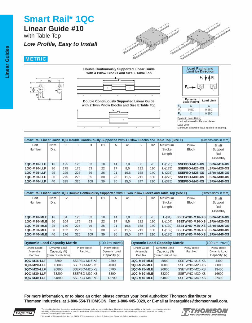
1QC-M16-LLF 8800 SSEPBO-M16-XS 22001QC-M20-LLF 16000 SSEPBO-M20-XS 40001QC-M25-LLF 26800 SSEPBO-M25-XS 67001QC-M30-LLF 33200 SSEPBO-M30-XS 83001QC-M40-LLF 54800 SSEPBO-M40-XS 13700
1QC-M16-MLE 8800 SSETWNO-M16-XS 44001QC-M20-MLE 16000 SSETWNO-M20-XS 80001QC-M25-MLE 26800 SSETWNO-M25-XS 134001QC-M30-MLE 33200 SSETWNO-M30-XS 166001QC-M40-MLE 54800 SSETWNO-M40-XS 27400
1QC-M16-MLE 16 84 125 53 18 14 7,0 86 70 L-(84) SSETWNO-M16-XS LSRA-M16-XS1QC-M20-MLE 20 104 175 63 22 17 8,5 132 110 L-(104) SSETWNO-M20-XS LSRA-M20-XS1QC-M25-MLE 25 130 225 76 26 21 10,5 168 140 L-(130) SSETWNO-M25-XS LSRA-M25-XS1QC-M30-MLE 30 152 275 85 30 23 11,5 211 180 L-(152) SSETWNO-M30-XS LSRA-M30-XS1QC-M40-MLE 40 176 325 109 39 30 15,0 247 210 L-(176) SSETWNO-M40-XS LSRA-M40-XS
1QC-M16-LLF 16 125 125 53 18 14 7,0 86 70 L-(125) SSEPBO-M16-XS LSRA-M16-XS1QC-M20-LLF 20 175 175 63 22 17 8,5 132 110 L-(175) SSEPBO-M20-XS LSRA-M20-XS1QC-M25-LLF 25 225 225 76 26 21 10,5 168 140 L-(225) SSEPBO-M25-XS LSRA-M25-XS1QC-M30-LLF 30 275 275 85 30 23 11,5 211 180 L-(275) SSEPBO-M30-XS LSRA-M30-XS1QC-M40-LLF 40 325 325 109 39 30 15,0 247 210 L-(325) SSEPBO-M40-XS LSRA-M40-XS
Page 134The specifications and data in this publication are believed to be accurate and reliable. However, it is the responsibility of the product user to determine thesuitability of Thomson products for a specific application. While defective products will be replaced without charge if promptly returned, no liability is assumed beyond such replacement.
* Trademark of Thomson Industries, Inc. THOMSON is registered in the U.S. Patent and Trademark Office and in other countries.
Line
ar G
uid
es
For more information, or to place an order, please contact your local authorized Thomson distributor orThomson Industries, at 1-800-554-THOMSON, Fax: 1-800-445-0329, or E-mail at [email protected].
Smart Rail* 1QCLinear Guide #10with Table TopLow Profile, Easy to Install
T2
T1
L
LT
B
H
B2
A A1
H1
Smart Rail Linear Guide 1QC Double Continuously Supported with 4 Pillow Blocks and Table Top (Size F) (Dimensions in mm)
Part Nom. T1 T H H1 A A1 B B2 Maximum Pillow ShaftNumber Dia. Stroke Block Support
Length RailAssembly
Smart Rail Linear Guide 1QC Double Continuously Supported with 2 Twin Pillow Blocks and Table Top (Size E) (Dimensions in mm)
Part Nom. T2 T H H1 A A1 B B2 Maximum Pillow ShaftNumber Dia. Stroke Block Support
Length RailAssembly
Double Continuously Supported Linear Guide with 4 Pillow Blocks and Size F Table Top
Double Continuously Supported Linear Guide with 2 Twin Pillow Blocks and Size E Table Top
METRIC
Dynamic Load Capacity Matrix (100 km travel)Linear Guide Dynamic Load Pillow Block Pillow Block
Assembly Capacity (N) Part No. Dynamic Load Part No. (Even Distribution) Capacity (N)
Dynamic Load Capacity Matrix (100 km travel)Linear Guide Dynamic Load Pillow Block Pillow Block
Assembly Capacity (N) Part No. Dynamic Load Part No. (Even Distribution) Capacity (N)
FcFtFs
C0.5C
C
C0.25C0.25C
DynamicLoad Rating Load Limit
Load Rating andLimit by Direction
Fc Ft
Fs
Dynamic Load RatingLoad value used in life calculation.Load LimitMaximum allowable load applied to bearing.

1QC-M16 125 70 40 13 M6 125 26 10,0 7,5 70 84 64 10 7,5 32 451QC-M20 175 110 45 16 M8 175 32 11,0 10,0 110 104 76 14 10,0 38 551QC-M25 225 140 60 20 M8 225 40 13,5 12,5 140 130 94 18 12,5 47 651QC-M30 275 180 68 20 M8 275 45 17,0 13,5 180 152 106 23 13,5 53 751QC-M40 325 210 86 25 M10 325 58 16,5 14,5 210 176 124 26 14,5 62 85
LSRA-M16-XS 16 18 14 7,0 40 20 M3 x 30 3,6LSRA-M20-XS 20 22 17 8,5 60 30 M4 x 35 5,5LSRA-M25-XS 25 26 21 10,5 60 30 M5 x 45 8,5LSRA-M30-XS 30 30 23 11,5 80 40 M6 x 50 13,0LSRA-M40-XS 40 39 30 15,0 105 52,5 M10 x 65 21,0
SSETWNO-M16-XS 16 84 64 21,5 32 0,34
SSETWNO-M20-XS 20 104 76 27,0 38 0,63
SSETWNO-M25-XS 25 130 94 33,6 47 1,18
SSETWNO-M30-XS 30 152 106 39,5 53 1,70
SSETWNO-M40-XS 40 176 124 45,5 62 3,18
SSEPBO-M16-XS 16 43 22 35 26,5 53 22,0 21,5 40 26 5,3 M6 66 0,17
SSEPBO-M20-XS 20 54 25 41 30,0 60 25,0 27,0 45 32 6,6 M8 60 0,30
SSEPBO-M25-XS 25 67 30 50 39,0 78 31,5 33,5 60 40 8,4 M10 60 0,57
SSEPBO-M30-XS 30 79 35 60 43,5 87 33,0 39,5 68 45 8,4 M10 60 0,87
SSEPBO-M40-XS 40 91 45 77 54,0 108 43,5 45,5 86 58 10,5 M12 60 1,62
The specifications and data in this publication are believed to be accurate and reliable. However, it is the responsibility of the product user to determine thesuitability of Thomson products for a specific application. While defective products will be replaced without charge if promptly returned, no liability is assumed beyond such replacement.
* Trademark of Thomson Industries, Inc. THOMSON is registered in the U.S. Patent and Trademark Office and in other countries.
Linear Guid
es
Page 135
For more information, or to place an order, please contact your local authorized Thomson distributor orThomson Industries, at 1-800-554-THOMSON, Fax: 1-800-445-0329, or E-mail at [email protected].
Smart Rail Linear Guide 1QC Components:■ 4 Super Smart Ball Bushing* open
type pillow blocks or 2 Super SmartBall Bushing open type twin pillowblocks.
■ 2 60 Case* LinearRace* shaft SupportRail Assemblies.
■ 1 mounting table top with work pieceand Ball Screw Assembly attachmentholes.
Smart Rail* Linear Guide 1QC Benefits:■ Requires only one part number to specify
the entire linear guide.■ Includes table top with standard tapped
holes for quick and easy mounting of thework piece.
■ Includes Ball Screw Assembly attachmentholes for ease of assembly and actuation.
■ Used in continuously supported applications when rigidity is required.
System All Table Tops Table Top Size F Table Top Size ET M J H6 F5(2) T1 J1 J4 J5 M1 T2 J3 J4 J5 J9 M2
Mounting Table Top (Dimensions in mm)
Specifying a Thomson Linear Guide:1. Determine the proper system for your load and liferequirements. 2. Select the part number. 3. Add the letter “L” followed by the overall length inmillimeters, as a suffix to the part number.
Part Numbering System
1QC-M16-MLE L600Linear Guide Linear GuideDesignation LengthNominal Diameter Type of Table Top
Type of Bearing Block Type of Support
Material: Aluminum Alloy Grey Anodized(2) Customer Mounting Hole
Part Nom. L1 H8 H9 B1 B9 J6 J7 J J1 N N2 α MassNumber Dia. Dia. Deg kg
Type SSETWNO Pillow BlocksType SSEPBO Pillow Blocks (Dimensions in mm)
Housing Material: Aluminum Alloy Grey Anodized Housing Material: Aluminum Alloy Grey Anodized
Part Nom. L2 J3 J8 J9 Mass
Number Dia. kg
Part Nominal H1 A A1 T4 Y N3(1) MassNumber Diameter kg/m
Type LSRA Low Profile LinearRace Shaft Support Rail Assembly (Dimensions in mm)
B9J
B1
L1
N
J1N2
H9
H8
αJ7
J6Access forLubricationM6 x 1
J3J9
L2 B9J
B1
N
H9
H8
α
N2
J8 J8
J6
Access forLubricationM6 x 1 (2 Plcs.)
Y T4
N3L
H1
A
Type SSEPBO Open Type Super Smart Ball Bushing Pillow Block
Type LSRA Low Profile LinearRace Shaft Support Rail Assembly
Mounting Table Top
Type SSETWNO Open Type Super Smart Ball Bushing Twin Pillow Block
J
J5
H6
M
M1, M2 T1, T2
J3
J9J1
F5
T
J4
LinearRace Shaft Support Rail Material: Black Oxided Steel(1) Each system is shipped with attachment screws as noted by N3 and cap plugs.If a non-standard screw length is required, it must be user supplied.
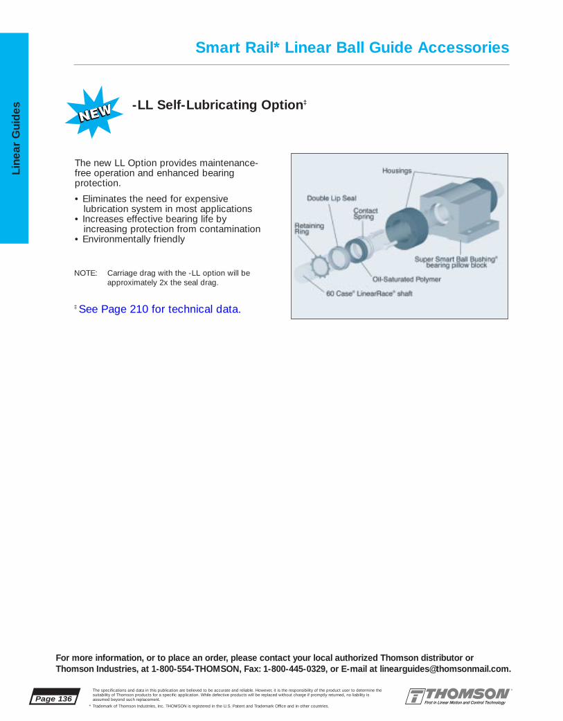
Page 136The specifications and data in this publication are believed to be accurate and reliable. However, it is the responsibility of the product user to determine thesuitability of Thomson products for a specific application. While defective products will be replaced without charge if promptly returned, no liability is assumed beyond such replacement.
* Trademark of Thomson Industries, Inc. THOMSON is registered in the U.S. Patent and Trademark Office and in other countries.
Line
ar G
uid
es -LL Self-Lubricating Option‡
The new LL Option provides maintenance-free operation and enhanced bearing protection.
• Eliminates the need for expensivelubrication system in most applications
• Increases effective bearing life byincreasing protection from contamination
• Environmentally friendly
NOTE: Carriage drag with the -LL option will beapproximately 2x the seal drag.
Smart Rail* Linear Ball Guide Accessories
‡ See Page 210 for technical data.
For more information, or to place an order, please contact your local authorized Thomson distributor orThomson Industries, at 1-800-554-THOMSON, Fax: 1-800-445-0329, or E-mail at [email protected].

The specifications and data in this publication are believed to be accurate and reliable. However, it is the responsibility of the product user to determine thesuitability of Thomson products for a specific application. While defective products will be replaced without charge if promptly returned, no liability is assumed beyond such replacement.
* Trademark of Thomson Industries, Inc. THOMSON is registered in the U.S. Patent and Trademark Office and in other countries.
Linear Guid
es
Page 137
3
2
1 4NEW
5NEW
67
9 1112
13
14
15
16
8NEW 10
NEW17NEW
For more information, or to place an order, please contact your local authorized Thomson distributor orThomson Industries, at 1-800-554-THOMSON, Fax: 1-800-445-0329, or E-mail at [email protected].
RoundWay Linear Roller Guides #11
HIGHEST LOADS, MOST RUGGED,HIGHEST SPEED AND ACCELERATION
RoundWay* Linear Roller Guides Offer:
■ Up to twenty times the load capacity of conventional linear ball bearings. This dramaticincrease allows for more compact machinedesigns with a reduction in hardware costs
■ Industry’s highest load capacity. RoundWayLinear Roller bearings handle up to 35tons/bearing and speeds up to 100 ft/second
■ Virtual insensitivity to contamination without concerns of stroke length reduction from waycovers
■ A self-aligning capability that reduces installationtime and cost by compensating for rail misalignment errors
■ Interchangeable components for quick, cost-effective machine maintenance.
■ Curved rollers running on a curved inner racewhich make this linear guide resistant to severeshock loads
■ Corrosion resistant versions for maximum performance in harsh environments.
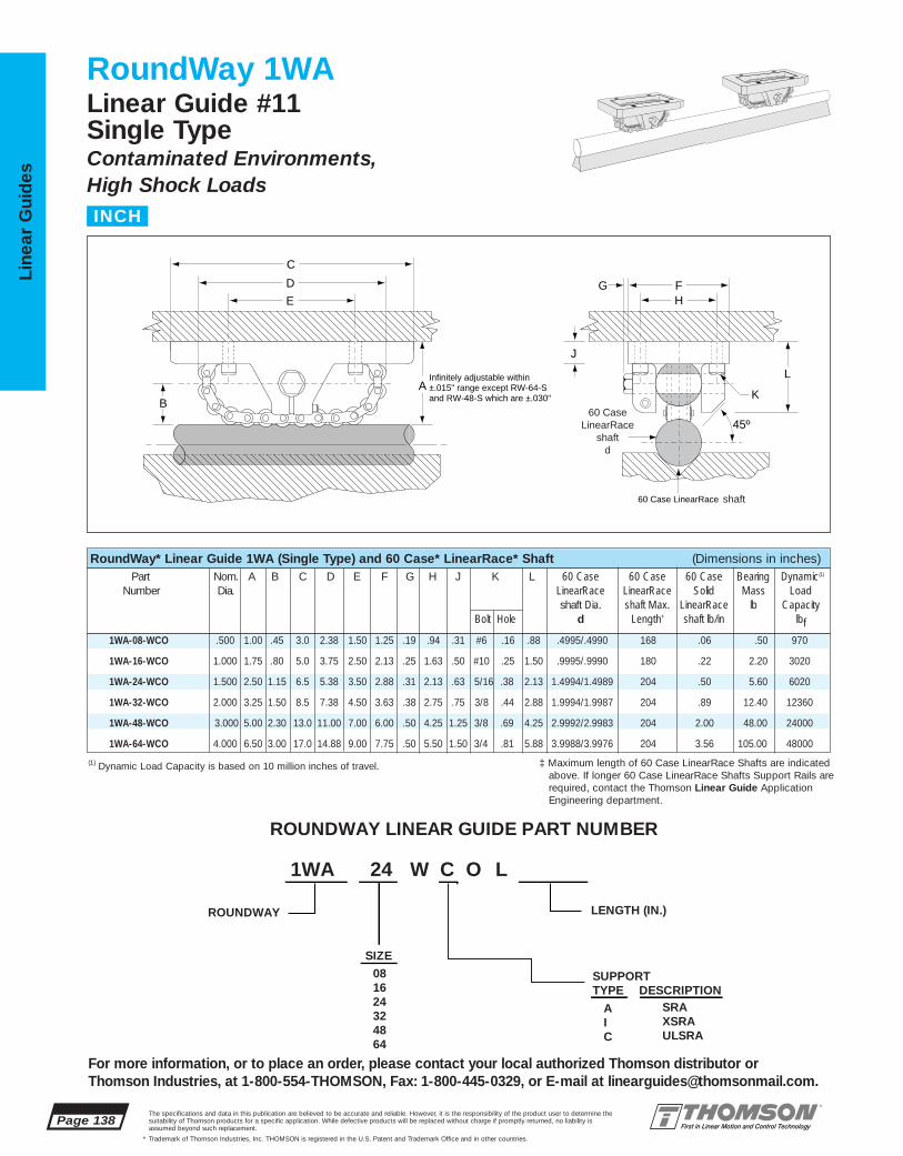
1WA-08-WCO .500 1.00 .45 3.0 2.38 1.50 1.25 .19 .94 .31 #6 .16 .88 .4995/.4990 168 .06 .50 970
1WA-16-WCO 1.000 1.75 .80 5.0 3.75 2.50 2.13 .25 1.63 .50 #10 .25 1.50 .9995/.9990 180 .22 2.20 3020
1WA-24-WCO 1.500 2.50 1.15 6.5 5.38 3.50 2.88 .31 2.13 .63 5/16 .38 2.13 1.4994/1.4989 204 .50 5.60 6020
1WA-32-WCO 2.000 3.25 1.50 8.5 7.38 4.50 3.63 .38 2.75 .75 3/8 .44 2.88 1.9994/1.9987 204 .89 12.40 12360
1WA-48-WCO 3.000 5.00 2.30 13.0 11.00 7.00 6.00 .50 4.25 1.25 3/8 .69 4.25 2.9992/2.9983 204 2.00 48.00 24000
1WA-64-WCO 4.000 6.50 3.00 17.0 14.88 9.00 7.75 .50 5.50 1.50 3/4 .81 5.88 3.9988/3.9976 204 3.56 105.00 48000
Page 138The specifications and data in this publication are believed to be accurate and reliable. However, it is the responsibility of the product user to determine thesuitability of Thomson products for a specific application. While defective products will be replaced without charge if promptly returned, no liability is assumed beyond such replacement.
* Trademark of Thomson Industries, Inc. THOMSON is registered in the U.S. Patent and Trademark Office and in other countries.
Line
ar G
uid
es
RoundWay 1WALinear Guide #11Single TypeContaminated Environments,High Shock Loads
Infinitely adjustable within±.015" range except RW-64-Sand RW-48-S which are ±.030"
60 Case LinearRace
A
E
D
C
B
J
H
45º
FG
L
K
shaft
60 CaseLinearRace
shaftd
(1) Dynamic Load Capacity is based on 10 million inches of travel.
RoundWay* Linear Guide 1WA (Single Type) and 60 Case* LinearRace* Shaft (Dimensions in inches)Part Nom. A B C D E F G H J K L 60 Case 60 Case 60 Case Bearing Dynamic(1)
Number Dia. LinearRace LinearRace Solid Mass Loadshaft Dia. shaft Max. LinearRace lb Capacity
Bolt Hole d Length‡ shaft lb/in lbf
For more information, or to place an order, please contact your local authorized Thomson distributor orThomson Industries, at 1-800-554-THOMSON, Fax: 1-800-445-0329, or E-mail at [email protected].
INCH
ROUNDWAY LINEAR GUIDE PART NUMBER
1WA 24 W C O L
LENGTH (IN.)ROUNDWAY
SIZE081624324864
SUPPORTTYPE DESCRIPTION
AIC
SRAXSRAULSRA
‡ Maximum length of 60 Case LinearRace Shafts are indicatedabove. If longer 60 Case LinearRace Shafts Support Rails arerequired, contact the Thomson Linear Guide ApplicationEngineering department.
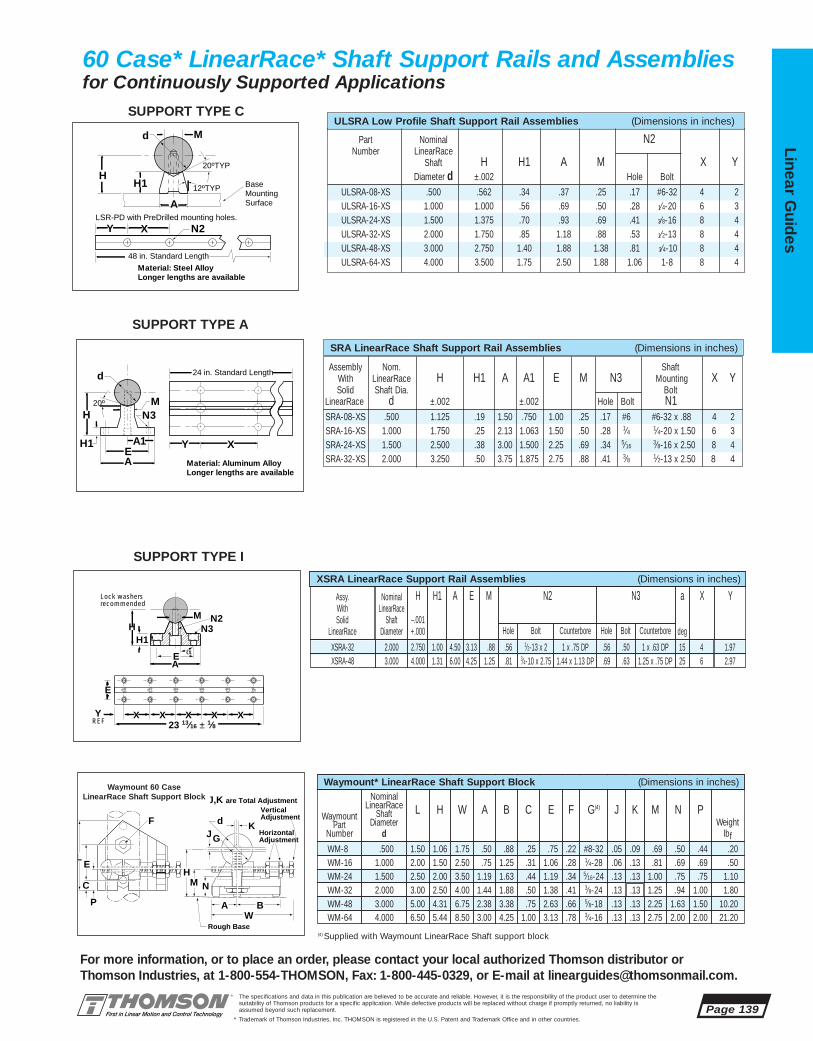
Assembly Nom. Shaft With LinearRace H H1 A A1 E M N3 Mounting X YSolid Shaft Dia. Bolt
LinearRace d ±.002 ±.002 Hole Bolt N1SRA-08-XS .500 1.125 .19 1.50 .750 1.00 .25 .17 #6 #6-32 x .88 4 2SRA-16-XS 1.000 1.750 .25 2.13 1.063 1.50 .50 .28 1⁄4 1⁄4-20 x 1.50 6 3SRA-24-XS 1.500 2.500 .38 3.00 1.500 2.25 .69 .34 5⁄16
3⁄8-16 x 2.50 8 4SRA-32-XS 2.000 3.250 .50 3.75 1.875 2.75 .88 .41 3⁄8 1⁄2-13 x 2.50 8 4
Part Nominal N2Number LinearRace
Shaft H H1 A M X YDiameter d ±.002 Hole Bolt
ULSRA-08-XS .500 .562 .34 .37 .25 .17 #6-32 4 2ULSRA-16-XS 1.000 1.000 .56 .69 .50 .28 1⁄4-20 6 3ULSRA-24-XS 1.500 1.375 .70 .93 .69 .41 3⁄8-16 8 4ULSRA-32-XS 2.000 1.750 .85 1.18 .88 .53 1⁄2-13 8 4ULSRA-48-XS 3.000 2.750 1.40 1.88 1.38 .81 3⁄4-10 8 4ULSRA-64-XS 4.000 3.500 1.75 2.50 1.88 1.06 1-8 8 4
The specifications and data in this publication are believed to be accurate and reliable. However, it is the responsibility of the product user to determine thesuitability of Thomson products for a specific application. While defective products will be replaced without charge if promptly returned, no liability is assumed beyond such replacement.
* Trademark of Thomson Industries, Inc. THOMSON is registered in the U.S. Patent and Trademark Office and in other countries.
Linear Guid
es
Page 139
For more information, or to place an order, please contact your local authorized Thomson distributor orThomson Industries, at 1-800-554-THOMSON, Fax: 1-800-445-0329, or E-mail at [email protected].
SRA LinearRace Shaft Support Rail Assemblies (Dimensions in inches)
60 Case* LinearRace* Shaft Support Rails and Assembliesfor Continuously Supported Applications
A
H
d
Y X
48 in. Standard Length
LSR-PD with PreDrilled mounting holes.
M
H1
20ºTYP
BaseMountingSurface
12ºTYP
N2
Material: Steel AlloyLonger lengths are available
A
A1E
HM
H1
N320º
Y X
Material: Aluminum AlloyLonger lengths are available
d 24 in. Standard Length
H1H
M
aEA
Lock washersrecommended
N2N3
E
XREFY X X X X
23 13⁄16 ± 1⁄8
WA
N
KF
Waymount Support Block
dJG
M
E
C
P B
H
L
HorizontalAdjustment
VerticalAdjustment
Rough Base
J,K are Total Adjustment
Waymount 60 Case LinearRace Shaft Support Block
ULSRA Low Profile Shaft Support Rail Assemblies (Dimensions in inches)
1.972.000 3.13XSRA-32 1 x .63 DP1 x .75 DP 15.56 .50.56 1⁄2-13 x 22.750 1.00 4.50 4.88
X
XSRA-48
NominalLinearRace
ShaftDiameter
EAssy.WithSolid
LinearRace
H
–.001+.000
H1 A N2 N3 Ya
deg
3.000 4.25 1.25 x .75 DP 2.9725.69 .63
Counterbore
4.000 1.31 6.00
Hole Bolt
1.44 x 1.13 DP.81 3⁄4-10 x 2.75
CounterboreHole Bolt
6
M
1.25
XSRA LinearRace Support Rail Assemblies (Dimensions in inches)
WM-8 .500 1.50 1.06 1.75 .50 .88 .25 .75 .22 #8-32 .05 .09 .69 .50 .44 .20
WM-24 1.500 2.50 2.00 3.50 1.19 1.63 .44 1.19 .34 5⁄16-24 .13 .13 1.00 .75 .75 1.10
WM-48 3.000 5.00 4.31 6.75 2.38 3.38 .75 2.63 .66 5⁄8-18 .13 .13 2.25 1.63 1.50 10.20
(4) Supplied with Waymount LinearRace Shaft support block
WaymountPart
Number
NominalLinearRace
ShaftDiameter
d
L H W A B C E F G(4) J K M N PWeight
lbf
WM-16 1.000 2.00 1.50 2.50 .75 1.25 .31 1.06 .28 1⁄4-28 .06 .13 .81 .69 .69 .50
WM-32 2.000 3.00 2.50 4.00 1.44 1.88 .50 1.38 .41 3⁄8-24 .13 .13 1.25 .94 1.00 1.80
WM-64 4.000 6.50 5.44 8.50 3.00 4.25 1.00 3.13 .78 3⁄4-16 .13 .13 2.75 2.00 2.00 21.20
Waymount* LinearRace Shaft Support Block (Dimensions in inches)
SUPPORT TYPE C
SUPPORT TYPE A
SUPPORT TYPE I
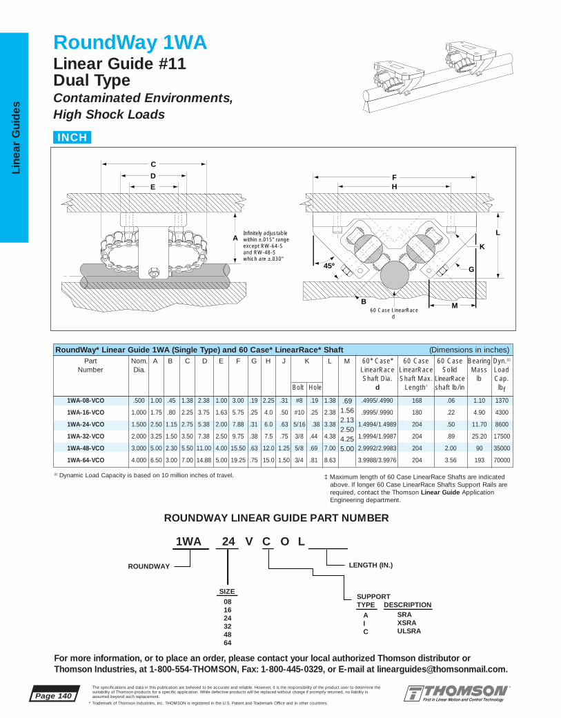
1WA-08-VCO .500 1.00 .45 1.38 2.38 1.00 3.00 .19 2.25 .31 #8 .19 1.38 .4995/.4990 168 .06 1.10 1370
1WA-16-VCO 1.000 1.75 .80 2.25 3.75 1.63 5.75 .25 4.0 .50 #10 .25 2.38 .9995/.9990 180 .22 4.90 4300
1WA-24-VCO 1.500 2.50 1.15 2.75 5.38 2.00 7.88 .31 6.0 .63 5/16 .38 3.38 1.4994/1.4989 204 .50 11.70 8600
1WA-32-VCO 2.000 3.25 1.50 3.50 7.38 2.50 9.75 .38 7.5 .75 3/8 .44 4.38 1.9994/1.9987 204 .89 25.20 17500
1WA-48-VCO 3.000 5.00 2.30 5.50 11.00 4.00 15.50 .63 12.0 1.25 5/8 .69 7.00 2.9992/2.9983 204 2.00 90 35000
1WA-64-VCO 4.000 6.50 3.00 7.00 14.88 5.00 19.25 .75 15.0 1.50 3/4 .81 8.63 3.9988/3.9976 204 3.56 193 70000
Page 140The specifications and data in this publication are believed to be accurate and reliable. However, it is the responsibility of the product user to determine thesuitability of Thomson products for a specific application. While defective products will be replaced without charge if promptly returned, no liability is assumed beyond such replacement.
* Trademark of Thomson Industries, Inc. THOMSON is registered in the U.S. Patent and Trademark Office and in other countries.
Line
ar G
uid
es
RoundWay 1WALinear Guide #11Dual TypeContaminated Environments,High Shock Loads
Infinitely adjustable within ±.015" range except RW-64-Sand RW-48-S which are ±.030"
60 Case LinearRaced
A
E
D
C
H
45º
B M
F
L
K
G
(1) Dynamic Load Capacity is based on 10 million inches of travel.
RoundWay* Linear Guide 1WA (Single Type) and 60 Case* LinearRace* Shaft (Dimensions in inches)Part Nom. A B C D E F G H J K L 60* Case* 60 Case 60 Case Bearing Dyn.(1)
Number Dia. LinearRace LinearRace Solid Mass LoadShaft Dia. Shaft Max. LinearRace lb Cap.
Bolt Hole d Length‡ shaft lb/in lbf
M
.691.562.132.504.255.00
For more information, or to place an order, please contact your local authorized Thomson distributor orThomson Industries, at 1-800-554-THOMSON, Fax: 1-800-445-0329, or E-mail at [email protected].
INCH
ROUNDWAY LINEAR GUIDE PART NUMBER
1WA 24 V C O L
LENGTH (IN.)ROUNDWAY
SIZE081624324864
SUPPORTTYPE DESCRIPTION
AIC
SRAXSRAULSRA
‡ Maximum length of 60 Case LinearRace Shafts are indicatedabove. If longer 60 Case LinearRace Shafts Support Rails arerequired, contact the Thomson Linear Guide ApplicationEngineering department.

Assembly Nom. ShaftWith LinearRace H H1 A A1 E M N3 Mounting X YSolid Shaft Dia. Bolt
LinearRace d ±.002 ±.002 Hole Bolt N1SRA-08-XS .500 1.125 .19 1.50 .750 1.00 .25 .17 #6 #6-32 x .88 4 2SRA-16-XS 1.000 1.750 .25 2.13 1.063 1.50 .50 .28 1⁄4 1⁄4-20 x 1.50 6 3SRA-24-XS 1.500 2.500 .38 3.00 1.500 2.25 .69 .34 5⁄16
3⁄8-16 x 2.50 8 4SRA-32-XS 2.000 3.250 .50 3.75 1.875 2.75 .88 .41 3⁄8 1⁄2-13 x 2.50 8 4
WM-8 .500 1.50 1.06 1.75 .50 .88 .25 .75 .22 8-32 .05 .09 .69 .50 .44 .20
WM-24 1.500 2.50 2.00 3.50 1.19 1.63 .44 1.19 .34 5⁄16-24 .13 .13 1.00 .75 .75 1.10
WM-48 3.000 5.00 4.31 6.75 2.38 3.38 .75 2.63 .66 5⁄8-18 .13 .13 2.25 1.63 1.50 10.20
1.972.000 3.13XSRA-32 1 x .63 DP1 x .75 DP 15.56 .50.56 1⁄2-13 x 22.750 1.00 4.50 4.88
Part Nominal N2Number LinearRace
Shaft H H1 A M X YDiameter d ±.002 Hole Bolt
ULSRA-08-XS .500 .562 .34 .37 .25 .17 #6-32 4 2ULSRA-16-XS 1.000 1.000 .56 .69 .50 .28 1⁄4-20 6 3ULSRA-24-XS 1.500 1.375 .70 .93 .69 .41 3⁄8-16 8 4ULSRA-32-XS 2.000 1.750 .85 1.18 .88 .53 1⁄2-13 8 4ULSRA-48-XS 3.000 2.750 1.40 1.88 1.38 .81 3⁄4-10 8 4ULSRA-64-XS 4.000 3.500 1.75 2.50 1.88 1.06 1-8 8 4
The specifications and data in this publication are believed to be accurate and reliable. However, it is the responsibility of the product user to determine thesuitability of Thomson products for a specific application. While defective products will be replaced without charge if promptly returned, no liability is assumed beyond such replacement.
* Trademark of Thomson Industries, Inc. THOMSON is registered in the U.S. Patent and Trademark Office and in other countries.
Linear Guid
es
Page 141
For more information, or to place an order, please contact your local authorized Thomson distributor orThomson Industries, at 1-800-554-THOMSON, Fax: 1-800-445-0329, or E-mail at [email protected].
X
XSRA-48
60 Case* LinearRace* Shaft Support Rails and Assembliesfor Continuously Supported Applications
A
H
d
Y X
48 in. Standard Length
LSR-PD with PreDrilled mounting holes.
M
H1
20ºTYP
BaseMountingSurface
12ºTYP
N2
Material: Steel AlloyLonger lengths are available
A
A1E
HM
H1
N320º
Y X
Material: Aluminum AlloyLonger lengths are available
d 24 in. Standard Length
H1H
M
aEA
Lock washersrecommended
N2N3
E
XREFY X X X X
23 13⁄16 ± 1⁄8
WA
N
KF
Waymount Support Block
dJG
M
E
C
P B
H
L
HorizontalAdjustment
VerticalAdjustment
Rough Base
J,K are Total Adjustment
WaymountPart
Number
NominalLinearRaceShaft Dia.
d
L H W A B C E F G(4) J K M N PWeight
lbf
WM-16 1.000 2.00 1.50 2.50 .75 1.25 .31 1.06 .28 1⁄4-28 .06 .13 .81 .69 .69 .50
WM-32 2.000 3.00 2.50 4.00 1.44 1.88 .50 1.38 .41 3⁄8-24 .13 .13 1.25 .94 1.00 1.80
WM-64 4.000 6.50 5.44 8.50 3.00 4.25 1.00 3.13 .78 3⁄4-16 .13 .13 2.75 2.00 2.00 21.20
Waymount* LinearRace Shaft Support Block (Dimensions in inches)Waymount 60 Case LinearRace Shaft Support Block
NominalLinearRace
ShaftDiameter
EAssy.WithSolid
LinearRace
H
–.001+.000
H1 A N2 N3 Ya
deg
3.000 4.25 1.25 x .75 DP 2.9725.69 .63
Counterbore
4.000 1.31 6.00
Hole Bolt
1.44 x 1.13 DP.81 3⁄4-10 x 2.75
CounterboreHole Bolt
6
M
1.25
XSRA LinearRace Shaft Support Rail Assemblies (Dimensions in inches)
ULSRA Low Profile Shaft Support Rail Assemblies (Dimensions in inches)
SRA LinearRace Shaft Support Rail Assemblies (Dimensions in inches)
(4) Supplied with Waymount LinearRace Shaft support block
SUPPORT TYPE C
SUPPORT TYPE A
SUPPORT TYPE I

Page 142The specifications and data in this publication are believed to be accurate and reliable. However, it is the responsibility of the product user to determine thesuitability of Thomson products for a specific application. While defective products will be replaced without charge if promptly returned, no liability is assumed beyond such replacement.
* Trademark of Thomson Industries, Inc. THOMSON is registered in the U.S. Patent and Trademark Office and in other countries.
Line
ar G
uid
es
For more information, or to place an order, please contact your local authorized Thomson distributor orThomson Industries, at 1-800-554-THOMSON, Fax: 1-800-445-0329, or E-mail at [email protected].
RoundWay Linear Roller BearingsRoundWay Operating Principle
Thomson invented the RoundWay* Linear roller bearing for use in high load, heavy duty applications.Each RoundWay bearing combines the high loadcapacity of hardened and ground steel recirculatingrollers with a rigid malleable iron pillow block provid-ing extremely high load capacity with smooth lineartravel. The RoundWay linear roller bearing comes inboth a single and dual version. A single RoundWaylinear roller bearing does not resist side loads and istherefore always used in conjunction with a dual version.
Each RoundWay linear roller bearing is designed foruse on 60 Case* LinearRace* shaft. The 60 CaseLinearRace shaft can be continuously supportedusing type LSR, SR, or XSR 60 Case LinearRaceshaft support rails or intermittently supported usingthe adjustable Waymount* LinearRace shaft supportstype WM.
The RoundWay linear roller bearing consists of fourbasic parts: the bearing race, the roller assembly, theeccentric trunnion pin and the mounting block. Therolling elements of a RoundWay linear roller bearingare a series of concave rollers interconnected andlinked by a chain assembly. As load is applied to themounting block it is transferred through the bearingrace and roller assembly to the supported 60 CaseLinearRace shaft. Connecting the mounting block to
the RoundWay bearing and roller assembly is aneccentric trunnion pin that allows the height of theRoundWay linear roller bearing to be adjusted tocompensate for variations in the mounting surfacesor the build-up of tolerances between component elements. The eccentric trunnion pin can also be used to preload the RoundWay bearing by eliminating internal bearing clearance. After the eccentric trunnionpin has been adjusted it can be held in place by simply tightening the lock screw.
Self-AligningThe RoundWay single and dual bearings are designedwith a built-in self-aligning capability that absorbsmisalignment caused by inaccuracies in carriage orbase machining. The RoundWay single bearing hasan additional built-in self-aligning capability thatallows it to absorb misalignment caused by twoslightly out of parallel 60 Case LinearRace shafts. This feature is realized when two RoundWay singlebearings are mounted on one 60 Case LinearRaceshaft and two dual RoundWay bearings are on a parallel 60 Case LinearRace shaft.
Standard mounting block
Unloaded rollersin return portionof circuit
Rollerassembly
Loadcarryingrollers
High carbon bearingquality steel inner race
Infinitely adjustable within±.015" range except RW-64-Sand RW-48-S which are ±.030"
Lock screw may be inserted from oppositeend of hole for improvedaccess
60 CaseLinearRaceShaft
Eccentrictrunnion pin
Standard mounting block
Bearingrace
Rollerassembly
Lockscrew
Eccentrictrunnionpin
60 Case LinearRaceShaft

The specifications and data in this publication are believed to be accurate and reliable. However, it is the responsibility of the product user to determine thesuitability of Thomson products for a specific application. While defective products will be replaced without charge if promptly returned, no liability is assumed beyond such replacement.
* Trademark of Thomson Industries, Inc. THOMSON is registered in the U.S. Patent and Trademark Office and in other countries.
Linear Guid
es
Page 143
For more information, or to place an order, please contact your local authorized Thomson distributor orThomson Industries, at 1-800-554-THOMSON, Fax: 1-800-445-0329, or E-mail at [email protected].
RoundWay Linear Roller Bearingsfor Continuously Supported Applications
RoundWay* Linear Roller Bearing (Single Type)• Available in 1⁄2 through 4 inch
diameters.• Load capacity range between 970
and 48,000 lbf.• Travel speeds up to 100 ft/s.• Accelerations up to 450 ft/s2.• Can be adjusted to compensate
for variations in the mounting surface.
• Self-aligning in all directions.• Designed to compensate for two
60 Case* LinearRace* shafts thatare slightly out of parallel
• Should always be used in conjunction with RoundWay Dualversion.
• Can be mounted in a custom housing.
• Available with a two piece sealthat retains lubrication while protecting the bearing from theingress of dirt or contaminants.
• Easily mounted to carriage withfour mounting bolts.
RoundWay Linear Roller Bearing (Dual Type)• Available in 1⁄2 through 4 inch
diameters.• Load capacity range between
1370 and 70,000 lbf.• Travel speeds up to 100 ft/s.• Accelerations up to 450 ft/s2.• Can be adjusted to compensate
for variations in the mounting surface.
• Self-aligning in all directions.
• Available with a two piece sealthat retains lubrication whileprotecting the bearing from theingress of dirt or contaminants.
• Easily mounted to carriage withfour mounting bolts.

Page 144The specifications and data in this publication are believed to be accurate and reliable. However, it is the responsibility of the product user to determine thesuitability of Thomson products for a specific application. While defective products will be replaced without charge if promptly returned, no liability is assumed beyond such replacement.
* Trademark of Thomson Industries, Inc. THOMSON is registered in the U.S. Patent and Trademark Office and in other countries.
Line
ar G
uid
es
A P P L I C A T I O N W O R K S H E E TP R O J E C T T I T L E :
N O T E S
For more information, or to place an order, please contact your local authorized Thomson distributor orThomson Industries, at 1-800-554-THOMSON, Fax: 1-800-445-0329, or E-mail at [email protected].
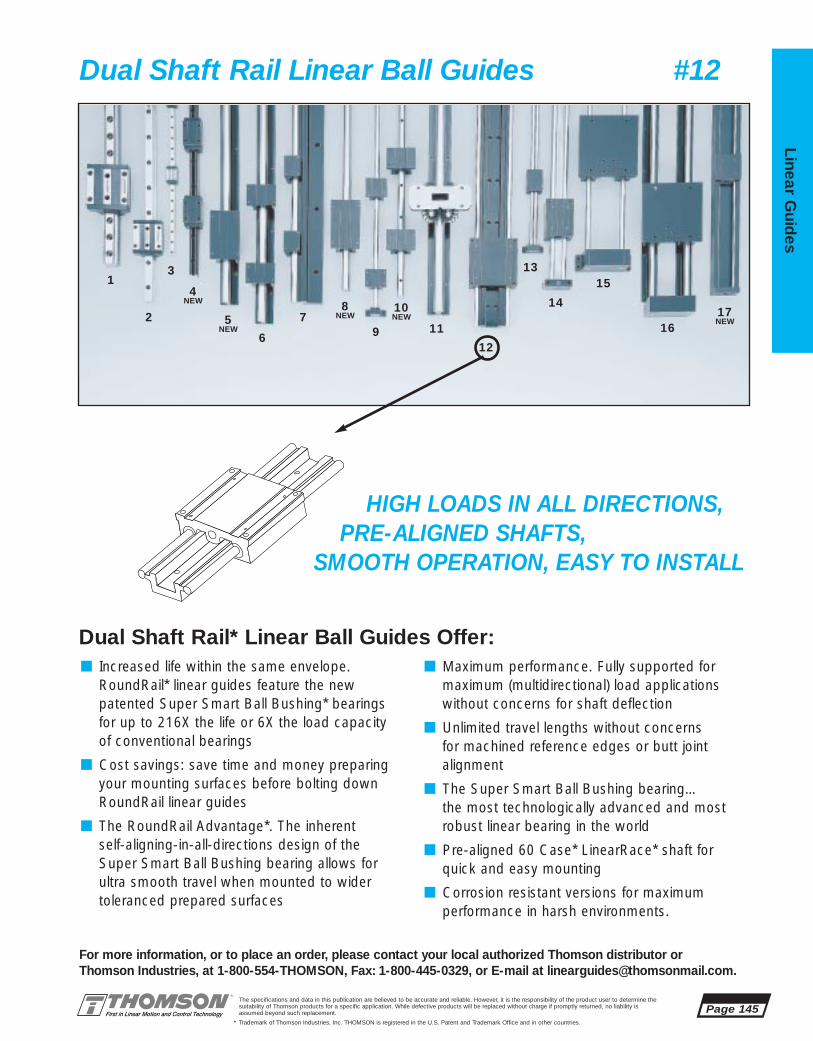
The specifications and data in this publication are believed to be accurate and reliable. However, it is the responsibility of the product user to determine thesuitability of Thomson products for a specific application. While defective products will be replaced without charge if promptly returned, no liability is assumed beyond such replacement.
* Trademark of Thomson Industries, Inc. THOMSON is registered in the U.S. Patent and Trademark Office and in other countries.
Linear Guid
es
Page 145
3
2
14
NEW
5NEW
6
79 11
12
13
14
15
16
8NEW
10NEW 17
NEW
For more information, or to place an order, please contact your local authorized Thomson distributor orThomson Industries, at 1-800-554-THOMSON, Fax: 1-800-445-0329, or E-mail at [email protected].
Dual Shaft Rail Linear Ball Guides #12
HIGH LOADS IN ALL DIRECTIONS,PRE-ALIGNED SHAFTS,
SMOOTH OPERATION, EASY TO INSTALL
Dual Shaft Rail* Linear Ball Guides Offer:■ Increased life within the same envelope.
RoundRail* linear guides feature the new patented Super Smart Ball Bushing* bearingsfor up to 216X the life or 6X the load capacity of conventional bearings
■ Cost savings: save time and money preparingyour mounting surfaces before bolting downRoundRail linear guides
■ The RoundRail Advantage*. The inherent self-aligning-in-all-directions design of the Super Smart Ball Bushing bearing allows for ultra smooth travel when mounted to wider toleranced prepared surfaces
■ Maximum performance. Fully supported for maximum (multidirectional) load applications without concerns for shaft deflection
■ Unlimited travel lengths without concerns for machined reference edges or butt joint alignment
■ The Super Smart Ball Bushing bearing…the most technologically advanced and mostrobust linear bearing in the world
■ Pre-aligned 60 Case* LinearRace* shaft forquick and easy mounting
■ Corrosion resistant versions for maximum performance in harsh environments.
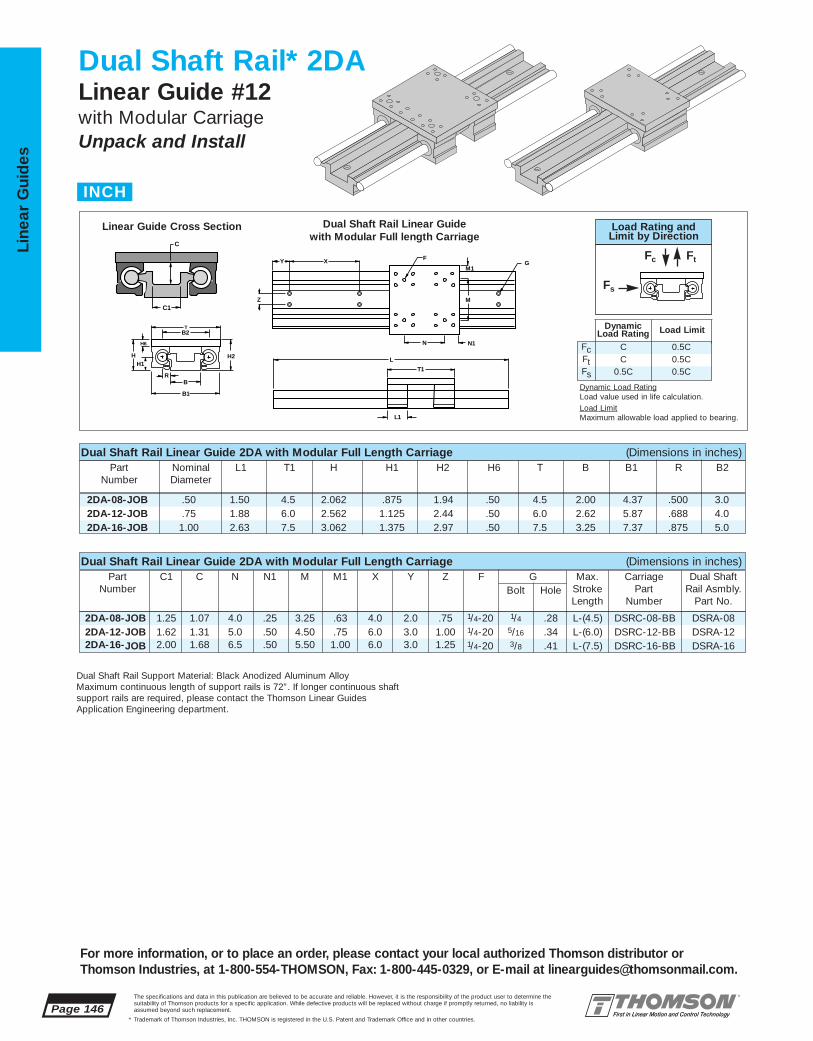
2DA-08-JOB .50 1.50 4.5 2.062 .875 1.94 .50 4.5 2.00 4.37 .500 3.02DA-12-JOB .75 1.88 6.0 2.562 1.125 2.44 .50 6.0 2.62 5.87 .688 4.02DA-16-JOB 1.00 2.63 7.5 3.062 1.375 2.97 .50 7.5 3.25 7.37 .875 5.0
2DA-08-JOB 1.25 1.07 4.0 .25 3.25 .63 4.0 2.0 .75 1/4-20 1/4 .28 L-(4.5) DSRC-08-BB DSRA-082DA-12-JOB 1.62 1.31 5.0 .50 4.50 .75 6.0 3.0 1.00 1/4-20 5/16 .34 L-(6.0) DSRC-12-BB DSRA-122DA-16-JOB 2.00 1.68 6.5 .50 5.50 1.00 6.0 3.0 1.25 1/4-20 3/8 .41 L-(7.5) DSRC-16-BB DSRA-16
Page 146The specifications and data in this publication are believed to be accurate and reliable. However, it is the responsibility of the product user to determine thesuitability of Thomson products for a specific application. While defective products will be replaced without charge if promptly returned, no liability is assumed beyond such replacement.
* Trademark of Thomson Industries, Inc. THOMSON is registered in the U.S. Patent and Trademark Office and in other countries.
Line
ar G
uid
es
For more information, or to place an order, please contact your local authorized Thomson distributor orThomson Industries, at 1-800-554-THOMSON, Fax: 1-800-445-0329, or E-mail at [email protected].
Dual Shaft Rail* 2DALinear Guide #12 with Modular CarriageUnpack and Install
FXY
Z
N N1
M
M1G
L
T1
H2
RB
B2
B1
HH1
H6
T
L1
C
C1
Dual Shaft Rail Linear Guide 2DA with Modular Full Length Carriage (Dimensions in inches)
Dual Shaft Rail Linear Guide 2DA with Modular Full Length Carriage (Dimensions in inches)
Part Nominal L1 T1 H H1 H2 H6 T B B1 R B2Number Diameter
Part C1 C N N1 M M1 X Y Z F G Max. Carriage Dual ShaftNumber Bolt Hole Stroke Part Rail Asmbly.
Length Number Part No.
Dual Shaft Rail Linear Guide with Modular Full length Carriage
Linear Guide Cross Section
Dual Shaft Rail Support Material: Black Anodized Aluminum Alloy Maximum continuous length of support rails is 72”. If longer continuous shaft support rails are required, please contact the Thomson Linear Guides Application Engineering department.
INCH
FcFtFs
CC
0.5C
0.5C0.5C0.5C
DynamicLoad Rating Load Limit
Load Rating andLimit by Direction
Fc Ft
Fs
Dynamic Load RatingLoad value used in life calculation.Load LimitMaximum allowable load applied to bearing.

2DA-08-JOB 480 120 7202DA-12-JOB 3200 800 64002DA-16-JOB 5400 1350 135002DA-08-KOA 480 240* 7202DA-12-KOA 3200 1600* 64002DA-16-KOA 5400 2700* 13500
2DA-08-KOA 1.25 1.07 .250 3.00 3.25 .63 4.0 2.0 .75 1/4-20 1/4 .28 L-(3.5) DSRC-08-BA DSRA-082DA-12-KOA 1.62 1.31 .250 4.00 4.50 .75 6.0 3.0 1.00 1/4-20 5/16 .34 L-(4.5) DSRC-12-BA DSRA-122DA-16-KOA 2.00 1.68 .375 5.25 5.50 1.00 6.0 3.0 1.25 1/4-20 3/8 .41 L-(6.0) DSRC-16-BA DSRA-16
2DA-08-KOA .500 1.50 3.5 2.062 .875 1.94 .50 4.5 2.00 .500 4.37 3.02DA-12-KOA .750 1.88 4.5 2.562 1.125 2.44 .50 6.0 2.62 .688 5.87 4.02DA-16-KOA 1.000 2.63 6.0 3.062 1.375 2.97 .50 7.5 3.25 .875 7.37 5.0
The specifications and data in this publication are believed to be accurate and reliable. However, it is the responsibility of the product user to determine thesuitability of Thomson products for a specific application. While defective products will be replaced without charge if promptly returned, no liability is assumed beyond such replacement.
* Trademark of Thomson Industries, Inc. THOMSON is registered in the U.S. Patent and Trademark Office and in other countries.
Linear Guid
es
Page 147
For more information, or to place an order, please contact your local authorized Thomson distributor orThomson Industries, at 1-800-554-THOMSON, Fax: 1-800-445-0329, or E-mail at [email protected].
Dual Shaft Rail* Linear Guide 2DA Benefits:■ Used in continuously supported
applications when rigidity is required.
■ Adaptable to any drive system.■ Pre-aligned and preassembled for
immediate installation and use.■ Designed for medium to heavy loads.
Dual Shaft Rail Linear Guide 2DA Components: †
■ 1 Dual LinearRace* shaft railassembly.
■ 1 modular carriage with 4 open type Super Smart Ball Bushing*pillow blocks.
Specifying this Thomson Linear Guide:1. Determine the proper Linear Guide for your loadand life requirements. 2. Select the part number. 3. Add the letter “L” followed by the overall length ininches, as a suffix to the part number.
Part Numbering System
2DA-12-JOB L24Linear Guide Linear GuideDesignation LengthNominal Diameter Type of Carriage
FXY
Z
N2 N1
M
M1G
L
T2
H2H1
R
B
B2
B1
H
H6
T
C
C1
Dual Shaft Rail Linear Guide 2DA with Modular Short Length Carriage (Dimensions in inches)
Dual Shaft Rail Linear Guide 2DA with Modular Short Length Carriage (Dimensions in inches)
Part Nominal L1 T2 H H1 H2 H6 T B R B1 B2Number Diameter
Part C1 C N1 N2 M M1 X Y Z F G Max. Carriage Dual Shaft Number Bolt Hole Stroke Part Rail Asmbly.
Length Number Part No.
Dual Shaft Rail Linear Guide with ModularShort length Carriage
Linear Guide Cross Section
Dual Shaft Rail Support Material: Black Anodized Aluminum Alloy Maximum continuous length of support rails is 72”. If longer continuous shaft support rails are required, please contact the Thomson Linear Guides Application Engineering department.
* Twin Pillow Block
Dynamic Load Rating (C) Matrix (4 million inches travel)Linear Guide Dynamic Load Pillow Block Dynamic
Assembly Rating, C (lbf) Dynamic Load Roll Moment Part No. (Even Distribution) Rating, C (lbf) Rating, C (in - lbf)
FcFtFs
CC
0.5C
0.5C0.5C0.5C
DynamicLoad Rating Load Limit
Load Rating andLimit by Direction
Fc Ft
Fs
Dynamic Load RatingLoad value used in life calculation.Load LimitMaximum allowable load applied to bearing.
† Super Ball Bushing bearings areused in .500 inch size carriages.

2DA-08-OOB 4.00 .25 4.00 .30 4.0 2.0 .75 .50 #10-32 1/4 .28 L-(4.5) DSRC-08-SB DSRA-082DA-12-OOB 5.25 .37 5.25 .42 6.0 3.0 1.00 .70 1/4-20 5/16 .34 L-(6.0) DSRC-12-SB DSRA-122DA-16-OOB 6.75 .37 6.75 .42 6.0 3.0 1.25 .90 5/16-18 3/8 .41 L-(7.5) DSRC-16-SB DSRA-16
2DA-08-OOB .50 4.5 1.625 .875 1.43 2.00 .500 4.6 3.0 .64 1.252DA-12-OOB .75 6.0 2.125 1.125 1.93 2.63 .688 6.1 4.0 .75 1.622DA-16-OOB 1.00 7.5 2.625 1.375 2.44 3.25 .875 7.6 5.0 .99 2.00
Page 148The specifications and data in this publication are believed to be accurate and reliable. However, it is the responsibility of the product user to determine thesuitability of Thomson products for a specific application. While defective products will be replaced without charge if promptly returned, no liability is assumed beyond such replacement.
* Trademark of Thomson Industries, Inc. THOMSON is registered in the U.S. Patent and Trademark Office and in other countries.
Line
ar G
uid
es
For more information, or to place an order, please contact your local authorized Thomson distributor orThomson Industries, at 1-800-554-THOMSON, Fax: 1-800-445-0329, or E-mail at [email protected].
Dual Shaft Rail* 2DALinear Guide #12 with Integrated CarriageUnpack and Install
F M1
X Y
Z
G
M
N N1
L
T1
B1
S
B2
H1
BR
H2 H
C1
C
Dual Shaft Rail Linear Guide 2DA with Integrated Carriage (Dimensions in inches)
Dual Shaft Rail Linear Guide 2DA with Integrated Carriage (Dimensions in inches)
Part Nominal T1 H H1 H2 B R B1 B2 C C1Number Diameter
Part N N1 M M1 X Y Z S F G Max. Carriage Dual ShaftNumber As Bolt Hole Stroke Part Rail Asmbly.
Extruded Length Number Part No.
Dual Shaft Rail Support Material: Black Anodized Aluminum Alloy Maximum continuous length of support rails is 72”. If longer continuous shaft support rails are required, please contact the Thomson Linear Guides Application Engineering department.
Dual Shaft Rail Linear Guide with Integrated full length Carriage
Rail Cross Section
INCH
FcFtFs
CC
0.5C
0.5C0.5C0.5C
DynamicLoad Rating Load Limit
Load Rating andLimit by Direction
Fc Ft
Fs
Dynamic Load RatingLoad value used in life calculation.Load LimitMaximum allowable load applied to bearing.

2DA-08-OOB 480 7202DA-12-OOB 3200 64002DA-16-OOB 5400 135002DA-08-OOA 480 7202DA-12-OOA 3200 64002DA-16-OOA 5400 13500
2DA-08-OOA .25 3.00 4.00 .30 4.0 2.0 .75 .50 #10-32 1/4 .28 L-(3.5) DSRC-08-SA DSRA-082DA-12-OOA .37 3.75 5.25 .42 6.0 3.0 1.00 .70 1/4-20 5/16 .34 L-(4.5) DSRC-12-SA DSRA-122DA-16-OOA .37 5.25 6.75 .42 6.0 3.0 1.25 .90 5/16-18 3/8 .41 L-(6.0) DSRC-16-SA DSRA-16
2DA-08-OOA .500 3.5 1.625 .875 1.43 2.00 .500 4.60 3.0 .64 1.252DA-12-OOA .750 4.5 2.125 1.125 1.93 2.63 .688 6.10 4.0 .75 1.622DA-16-OOA 1.000 6.0 2.625 1.375 2.44 3.25 .875 7.60 5.0 .99 2.00
The specifications and data in this publication are believed to be accurate and reliable. However, it is the responsibility of the product user to determine thesuitability of Thomson products for a specific application. While defective products will be replaced without charge if promptly returned, no liability is assumed beyond such replacement.
* Trademark of Thomson Industries, Inc. THOMSON is registered in the U.S. Patent and Trademark Office and in other countries.
Linear Guid
es
Page 149
For more information, or to place an order, please contact your local authorized Thomson distributor orThomson Industries, at 1-800-554-THOMSON, Fax: 1-800-445-0329, or E-mail at [email protected].
Dual Shaft Rail* Linear Guide 2DA Benefits:■ Used in continuously supported
applications when rigidity is required.
■ Adaptable to any drive system.■ Pre-aligned and preassembled for
immediate installation and use.■ Designed for medium to heavy loads.
Dual Shaft Rail Linear Guide 2DA Components:†
■ 1 Dual LinearRace* shaft railassembly.
■ 1 integrated carriage with 4 open type Super Smart Ball Bushing* bearings.
Specifying this Thomson Linear Guide:1. Determine the proper Linear Guide for your loadand life requirements. 2. Select the part number. 3. Add the letter “L” followed by the overall length ininches, as a suffix to the part number.
Part Numbering System
2DA-12-OOB L24Linear Guide Linear GuideDesignation LengthNominal Diameter Type of Carriage
B1
S
B2
H1
BR
H2 H
LT2
N2 N1
M
X YF
G
Z
M1C1
C
Dual Shaft Rail Linear Guide 2DA with Integrated Carriage (Dimensions in inches)
Dual Shaft Rail Linear Guide 2DA with Integrated Carriage (Dimensions in inches)
Part Nominal T2 H H1 H2 B R B1 B2 C C1Number Diameter
Part N N2 M M1 X Y Z S F G Max. Carriage Dual ShaftNumber As Bolt Hole Stroke Part Rail Asmbly.
Extruded Length Number Part No.
Dual Shaft Rail Support Material: Black Anodized Aluminum Alloy Maximum continuous length of support rails is 72”. If longer continuous shaft support rails are required, please contact the Thomson Linear GuidesApplication Engineering department.
Dual Shaft Rail Linear Guide with Integrated short length Carriage
Rail Cross Section
Dynamic Load Rating (C) Matrix (4 million inches travel)
Linear Guide Dynamic Load DynamicAssembly Rating, C (lbf) Roll Moment Part No. (Even Distribution) Rating, C (in - lbf)
Note: Above load ratings used for life calculations. Load limit of assembly 50%.
FcFtFs
CC
0.5C
0.5C0.5C0.5C
DynamicLoad Rating Load Limit
Load Rating andLimit by Direction
Fc Ft
Fs
Dynamic Load RatingLoad value used in life calculation.Load LimitMaximum allowable load applied to bearing.
† Super Ball Bushing* bearings are used in 500 inch size carriages

2DA-08-OOK 100 5 105 5,9 120 60 20 13 M5 M6 L-(110) DSRC-08-SK DSRA-08M2DA-12-OOK 130 10 135 10,0 150 75 25 18 M6 M8 L-(150) DSRC-12-SK DSRA-12M2DA-16-OOK 170 10 175 9,0 200 100 30 23 M8 M10 L-(190) DSRC-16-SK DSRA-16M
2DA-08-OOK 110 41 22,2 36,3 50,8 12,7 116,8 76,2 16 322DA-12-OOK 150 54 28,6 49,0 66,8 17,5 155 101,6 19 412DA-16-OOK 190 66 34,9 61,3 82,5 22,3 193 127 25 51
Page 150The specifications and data in this publication are believed to be accurate and reliable. However, it is the responsibility of the product user to determine thesuitability of Thomson products for a specific application. While defective products will be replaced without charge if promptly returned, no liability is assumed beyond such replacement.
* Trademark of Thomson Industries, Inc. THOMSON is registered in the U.S. Patent and Trademark Office and in other countries.
Line
ar G
uid
es
For more information, or to place an order, please contact your local authorized Thomson distributor orThomson Industries, at 1-800-554-THOMSON, Fax: 1-800-445-0329, or E-mail at [email protected].
F M1
X Y
Z
G
M
N N1
L
T1
B1
S
B2
H1
BR
H2 H
C1
C
Dual Shaft Rail Linear Guidewith Integrated Carriage (Full Length)
Dual Shaft Rail SupportCross Section
Dual Shaft Rail Linear Guide 2DA with Integrated Carriage (Dimensions in mm)
Dual Shaft Rail Linear Guide 2DA with Integrated Carriage (Dimensions in mm)
Part T1 H H1 H2 B R B1 B2 C C1Number
Part N N1 M M1 X Y Z S F G Max. Carriage Dual ShaftNumber As Stroke Part Rail Asmbly.
Extruded Length Number Part No.
Maximum continuous length of 2DA LinearRace* shaft support rail is 1828 mm. If longer continuous one-piece LinearRace Shaft support rails are required, contact the Thomson Systems Application Engineering Department.
Dual Shaft Rail* 2DALinear Guide #12 with Integrated CarriageUnpack and Install
METRIC
FcFtFs
CC
0.5C
0.5C0.5C0.5C
DynamicLoad Rating Load Limit
Load Rating andLimit by Direction
Fc Ft
Fs
Dynamic Load RatingLoad value used in life calculation.Load LimitMaximum allowable load applied to bearing.

2DA-08-OOK 2140 822DA-12-OOK 14250 7252DA-16-OOK 24000 15252DA-08-OOJ 2140 822DA-12-OOJ 14250 7252DA-16-OOJ 24000 1525
2DA-08-OOJ 5 75 105 5,9 120 60 20 13 M5 M6 L-(85) DSRC-08-SJ DSRA-08M2DA-12-OOJ 10 90 135 10,0 150 75 25 18 M6 M8 L-(110) DSRC-12-SJ DSRA-12M2DA-16-OOJ 10 130 175 9,0 200 100 30 23 M8 M10 L-(150) DSRC-16-SJ DSRA-16M
2DA-08-OOJ 85 41 22,2 36,3 50,8 12,7 116,8 76,2 16 322DA-12-OOJ 110 54 28,6 49,0 66,8 17,5 155 101,6 19 41,32DA-16-OOJ 150 66 34,9 61,2 82,4 22,3 193 127 25 50,8
The specifications and data in this publication are believed to be accurate and reliable. However, it is the responsibility of the product user to determine thesuitability of Thomson products for a specific application. While defective products will be replaced without charge if promptly returned, no liability is assumed beyond such replacement.
* Trademark of Thomson Industries, Inc. THOMSON is registered in the U.S. Patent and Trademark Office and in other countries.
Linear Guid
es
Page 151
For more information, or to place an order, please contact your local authorized Thomson distributor orThomson Industries, at 1-800-554-THOMSON, Fax: 1-800-445-0329, or E-mail at [email protected].
Dual Shaft Rail* Linear Guide 2DA Benefits:■ Used in continuously supported
applications when rigidity is required.
■ Adaptable to any drive system.■ Pre-aligned and preassembled for
immediate installation and use.■ Designed for medium to heavy loads.
Dual Shaft Rail Linear Guide 2DA Components:†
■ 1 Dual LinearRace* shaft railassembly
■ 1 integrated carriage with 4 open type Super Smart Ball Bushing* bearings.
Specifying this Thomson Linear Guide:1. Determine the proper Linear Guide for your loadand life requirements. 2. Select the part number.3. Add the letter “L” followed by the overall length inmillimeters, as a suffix to the part number.
Part Numbering System
2DA-12-OOK L600Linear Guide Linear GuideDesignation LengthNominal Diameter Type of Carriage
B1
S
B2
H1
BR
H2 H
LT2
N2 N1
M
X YF
G
Z
M1
C1
C
Dual Shaft Rail Linear Guide 2DA with Integrated Carriage (Dimensions in mm)Part N1 N2 M M1 X Y Z S F G Max. Carriage Dual Shaft
Number As Stroke Part Rail Asmbly.Extruded Length Number Part No.
Dual Shaft Rail Linear Guide 2DA with Integrated Carriage (Dimensions in mm)Part T2 H H1 H2 B R B1 B2 C C1
Number
Maximum continuous length of 2DA LinearRace* Shaft support rail is 1828 mm. If longer continuous one-piece LinearRace shaft support rails are required, contactthe Thomson Systems Application Engineering Department.
Dual Shaft Rail Linear Guidewith Integrated Carriage (Short Length)
Dual Shaft Rail SupportCross Section
Dynamic Load Rating (C) Matrix (100 km travel)Linear Guide Dynamic Load Dynamic
Assembly Rating, C (N) Roll MomentPart No. (Even Distribution) Rating, C (N • M)
FcFtFs
CC
0.5C
0.5C0.5C0.5C
DynamicLoad Rating Load Limit
Load Rating andLimit by Direction
Fc Ft
Fs
Dynamic Load RatingLoad value used in life calculation.Load LimitMaximum allowable load applied to bearing.
† Super Ball Bushing* bearings are used in 500 inch size carriages
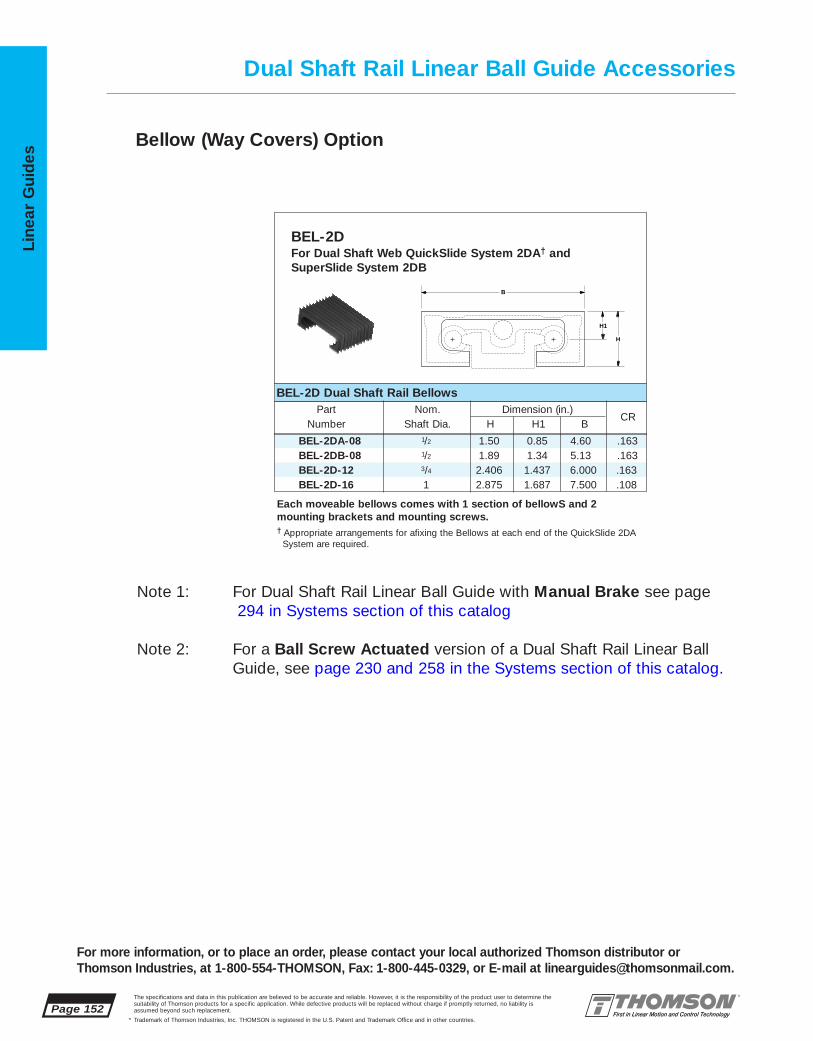
BEL-2DA-08 1/2 1.50 0.85 4.60 .163BEL-2DB-08 1/2 1.89 1.34 5.13 .163BEL-2D-12 3/4 2.406 1.437 6.000 .163BEL-2D-16 1 2.875 1.687 7.500 .108
Page 152The specifications and data in this publication are believed to be accurate and reliable. However, it is the responsibility of the product user to determine thesuitability of Thomson products for a specific application. While defective products will be replaced without charge if promptly returned, no liability is assumed beyond such replacement.
* Trademark of Thomson Industries, Inc. THOMSON is registered in the U.S. Patent and Trademark Office and in other countries.
Line
ar G
uid
es
Dual Shaft Rail Linear Ball Guide Accessories
Note 1: For Dual Shaft Rail Linear Ball Guide with Manual Brake see page294 in Systems section of this catalog
Note 2: For a Ball Screw Actuated version of a Dual Shaft Rail Linear BallGuide, see page 230 and 258 in the Systems section of this catalog.
For more information, or to place an order, please contact your local authorized Thomson distributor orThomson Industries, at 1-800-554-THOMSON, Fax: 1-800-445-0329, or E-mail at [email protected].
Each moveable bellows comes with 1 section of bellowS and 2 mounting brackets and mounting screws.† Appropriate arrangements for afixing the Bellows at each end of the QuickSlide 2DA
System are required.
B
H
H1
BEL-2DFor Dual Shaft Web QuickSlide System 2DA† and SuperSlide System 2DB
BEL-2D Dual Shaft Rail BellowsPart Nom. Dimension (in.)
Number Shaft Dia. H H1 B
Bellow (Way Covers) Option
CR

13
The specifications and data in this publication are believed to be accurate and reliable. However, it is the responsibility of the product user to determine thesuitability of Thomson products for a specific application. While defective products will be replaced without charge if promptly returned, no liability is assumed beyond such replacement.
* Trademark of Thomson Industries, Inc. THOMSON is registered in the U.S. Patent and Trademark Office and in other countries.
Linear Guid
es
Page 153
3
2
14
NEW
5NEW
6
79 11
12
1514
16
8NEW
10NEW
17NEW
For more information, or to place an order, please contact your local authorized Thomson distributor orThomson Industries, at 1-800-554-THOMSON, Fax: 1-800-445-0329, or E-mail at [email protected].
Twin Shaft Linear Ball Guides #13
EASY TO INSTALL, ULTRA COMPACT,HIGH SPEED, SMOOTH OPERATION
Twin Shaft* Linear Ball Guides Offer:
■ Pre-aligned shafts, very compact, ultra smooth travel
■ Pre-aligned shafts, end supported for gantrystyle or ‘bridge’ applications
■ Available in horizontal and vertical orientationsfor increased mounting flexibility
■ Compact, twin shaft design for use in applications with over turning loads
■ End supported for quick and easy installation
■ RoundRail* linear guides feature the new patented Super Smart Ball Bushing* bearing for up to 216X the life or 6X the load capacity of conventional bearings
■ Cost savings: save time and money preparingyour mounting surfaces before bolting downRoundRail linear guides
■ Corrosion resistant versions for maximum performance in harsh environments.
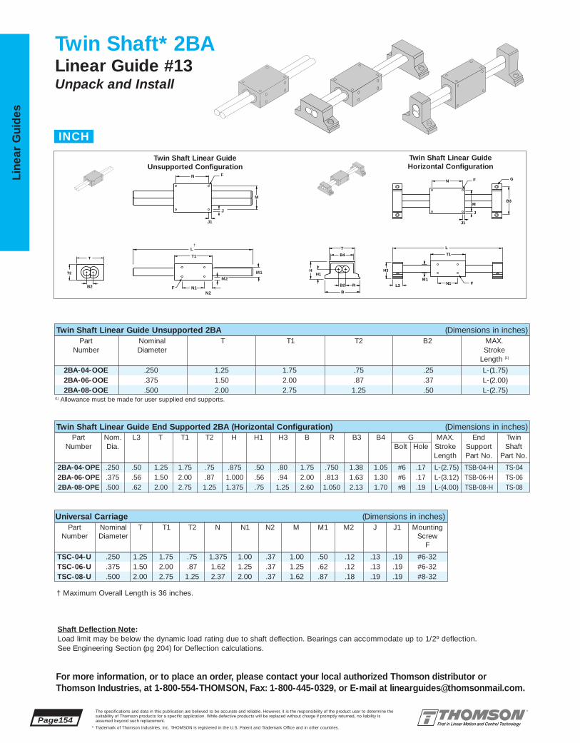
TSC-04-U .250 1.25 1.75 .75 1.375 1.00 .37 1.00 .50 .12 .13 .19 #6-32TSC-06-U .375 1.50 2.00 .87 1.62 1.25 .37 1.25 .62 .12 .13 .19 #6-32TSC-08-U .500 2.00 2.75 1.25 2.37 2.00 .37 1.62 .87 .18 .19 .19 #8-32
2BA-04-OPE .250 .50 1.25 1.75 .75 .875 .50 .80 1.75 .750 1.38 1.05 #6 .17 L-(2.75) TSB-04-H TS-042BA-06-OPE .375 .56 1.50 2.00 .87 1.000 .56 .94 2.00 .813 1.63 1.30 #6 .17 L-(3.12) TSB-06-H TS-062BA-08-OPE .500 .62 2.00 2.75 1.25 1.375 .75 1.25 2.60 1.050 2.13 1.70 #8 .19 L-(4.00) TSB-08-H TS-08
2BA-04-OOE .250 1.25 1.75 .75 .25 L-(1.75)2BA-06-OOE .375 1.50 2.00 .87 .37 L-(2.00)2BA-08-OOE .500 2.00 2.75 1.25 .50 L-(2.75)
Page154The specifications and data in this publication are believed to be accurate and reliable. However, it is the responsibility of the product user to determine thesuitability of Thomson products for a specific application. While defective products will be replaced without charge if promptly returned, no liability is assumed beyond such replacement.
* Trademark of Thomson Industries, Inc. THOMSON is registered in the U.S. Patent and Trademark Office and in other countries.
Line
ar G
uid
es
For more information, or to place an order, please contact your local authorized Thomson distributor orThomson Industries, at 1-800-554-THOMSON, Fax: 1-800-445-0329, or E-mail at [email protected].
Twin Shaft* 2BALinear Guide #13Unpack and Install
N F G
B3
J1
J
M
L
T1
FN1M1
L3
H3
T
B4
B2 R
B
HH1
N F
J1
J
L
T1
F N1B2
N2
M2M1
M
T2
T
†
Twin Shaft Linear Guide Unsupported 2BA (Dimensions in inches)Part Nominal T T1 T2 B2 MAX.
Number Diameter StrokeLength (1)
Twin Shaft Linear Guide End Supported 2BA (Horizontal Configuration) (Dimensions in inches)Part Nom. L3 T T1 T2 H H1 H3 B R B3 B4 G MAX. End Twin
Number Dia. Bolt Hole Stroke Support ShaftLength Part No. Part No.
Universal Carriage (Dimensions in inches)Part Nominal T T1 T2 N N1 N2 M M1 M2 J J1 Mounting
Number Diameter ScrewF
(1) Allowance must be made for user supplied end supports.
Twin Shaft Linear GuideUnsupported Configuration
Twin Shaft Linear GuideHorizontal Configuration
INCH
Shaft Deflection Note:Load limit may be below the dynamic load rating due to shaft deflection. Bearings can accommodate up to 1/2º deflection. See Engineering Section (pg 204) for Deflection calculations.
† Maximum Overall Length is 36 inches.

2BA-04-ONE 10 2.52BA-06-ONE 20 7.42BA-08-ONE 50 25
2BA-04-OOE 10 2.52BA-06-OOE 20 7.42BA-08-OOE 50 25
2BA-04-OPE 10 2.52BA-06-OPE 20 7.42BA-08-OPE 50 25
2BA-04-ONE .250 .50 1.25 1.75 .75 1.375 1.50 .625 1.31 .750 1.13 .68 #6 .17 L-(2.75) TSB-04-V TS-042BA-06-ONE .375 .56 1.50 2.00 .87 1.620 1.62 .688 1.56 .813 1.25 .80 #6 .17 L-(3.12) TSB-06-V TS-062BA-08-ONE .500 .62 2.00 2.75 1.25 2.125 2.00 .875 2.00 1.000 1.50 1.10 #8 .19 L-(4.00) TSB-08-V TS-08
The specifications and data in this publication are believed to be accurate and reliable. However, it is the responsibility of the product user to determine thesuitability of Thomson products for a specific application. While defective products will be replaced without charge if promptly returned, no liability is assumed beyond such replacement.
* Trademark of Thomson Industries, Inc. THOMSON is registered in the U.S. Patent and Trademark Office and in other countries.
Linear Guid
es
Page 155
For more information, or to place an order, please contact your local authorized Thomson distributor orThomson Industries, at 1-800-554-THOMSON, Fax: 1-800-445-0329, or E-mail at [email protected].
Twin Shaft* Linear Guide 2BA Benefits:■ Used when spanning or bridging
a gap.■ Twin welded LinearRace* shaft
design resists torque.■ Compact low profile design allows
for minimal machine size.■ Designed to move light loads with
virtually frictionless travel.
Twin Shaft Linear Guide 2BA Components:■ Universal integrated, carriage with
4 special open type Super Ball Bushing* bearings.
■ Twin welded 60 Case* LinearRaceshafts.
■ 2 vertical or horizontal double end supports.
Specifying this Thomson Linear Guide:1. Determine the proper Linear Guide for your loadand life requirements. 2. Select the part number. 3. Add the letter “L” followed by the overall length ininches, as a suffix to the part number.
Part Numbering System
2BA-08-ONE L24Linear Guide Linear GuideDesignation LengthNominal Diameter Type of Carriage
Type of Support
B4
T2
H B2
RB
H1
H3
L3
L
T1
F
B3
GF
T2
T N1
M1
N2
M2
J1
J
M
N
T1
Maximum Stroke Lengthis determined by subtracting thecarriage a length (T1) and 2xthe end support length (L3) fromthe total linear guide length.
For optimal performance andsmooth anti-friction motion 2BA systems are offered without seals.
Twin Shaft Linear Guide End Supported 2BA (Vertical Configuration) (Dimensions in inches)Part Nom. L3 T T1 T2 H B H1 H3 R B3 B4 G Max. End Twin
Number Dia. Bolt Hole Stroke Support ShaftLength Part No. Part No.
Twin Shaft Linear GuideVertical Configuration
Twin Shaft Linear GuideUniversal Carriage
Dynamic Load Capacity Matrix (4 million inches travel)
Linear Guide Dynamic Load Dynamic Assembly Capacity (lbf) Roll MomentPart No. (Even Distribution) Capacity (in - lbf)
Dynamic Load Capacity Matrix (4 million inches travel)
Linear Guide Dynamic Load Dynamic Assembly Capacity (lbf) Roll MomentPart No. (Even Distribution) Capacity (in - lbf)
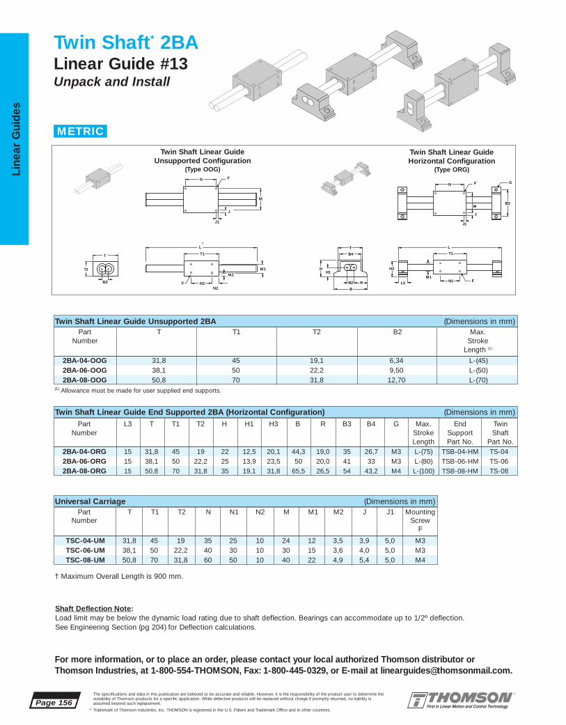
TSC-04-UM 31,8 45 19 35 25 10 24 12 3,5 3,9 5,0 M3TSC-06-UM 38,1 50 22,2 40 30 10 30 15 3,6 4,0 5,0 M3TSC-08-UM 50,8 70 31,8 60 50 10 40 22 4,9 5,4 5,0 M4
2BA-04-ORG 15 31,8 45 19 22 12,5 20,1 44,3 19,0 35 26,7 M3 L-(75) TSB-04-HM TS-042BA-06-ORG 15 38,1 50 22,2 25 13,9 23,5 50 20,0 41 33 M3 L-(80) TSB-06-HM TS-062BA-08-ORG 15 50,8 70 31,8 35 19,1 31,8 65,5 26,5 54 43,2 M4 L-(100) TSB-08-HM TS-08
2BA-04-OOG 31,8 45 19,1 6,34 L-(45)2BA-06-OOG 38,1 50 22,2 9,50 L-(50)2BA-08-OOG 50,8 70 31,8 12,70 L-(70)
Page 156The specifications and data in this publication are believed to be accurate and reliable. However, it is the responsibility of the product user to determine thesuitability of Thomson products for a specific application. While defective products will be replaced without charge if promptly returned, no liability is assumed beyond such replacement.
* Trademark of Thomson Industries, Inc. THOMSON is registered in the U.S. Patent and Trademark Office and in other countries.
Line
ar G
uid
es
For more information, or to place an order, please contact your local authorized Thomson distributor orThomson Industries, at 1-800-554-THOMSON, Fax: 1-800-445-0329, or E-mail at [email protected].
Twin Shaft* 2BALinear Guide #13Unpack and Install
N F G
B3
J1
J
M
L
T1
FN1M1
L3
H3
T
B4
B2 R
B
HH1
N F
J1
J
L
T1
F N1B2
N2
M2M1
M
T2
T
†
Twin Shaft Linear Guide Unsupported 2BA (Dimensions in mm)Part T T1 T2 B2 Max.
Number StrokeLength (1)
Twin Shaft Linear Guide End Supported 2BA (Horizontal Configuration) (Dimensions in mm)Part L3 T T1 T2 H H1 H3 B R B3 B4 G Max. End Twin
Number Stroke Support ShaftLength Part No. Part No.
Universal Carriage (Dimensions in mm)Part T T1 T2 N N1 N2 M M1 M2 J J1 Mounting
Number ScrewF
(1) Allowance must be made for user supplied end supports.
Twin Shaft Linear GuideUnsupported Configuration
(Type OOG)
Twin Shaft Linear GuideHorizontal Configuration
(Type ORG)
METRIC
Shaft Deflection Note:Load limit may be below the dynamic load rating due to shaft deflection. Bearings can accommodate up to 1/2º deflection. See Engineering Section (pg 204) for Deflection calculations.
† Maximum Overall Length is 900 mm.

2BA-04-OSG 45 2852BA-06-OSG 90 8552BA-08-OSG 225 2860
2BA-04-OOG 45 2852BA-06-OOG 90 8552BA-08-OOG 225 2860
2BA-04-ORG 45 2852BA-06-ORG 90 8552BA-08-ORG 225 2860
2BA-04-OSG 15 31,8 45 19 35 16 33,4 18,95 38 28 17,3 M3 L-(75) TSB-04-VM TS-04 2BA-06-OSG 15 38,1 50 22,2 40 16,2 38,4 20,25 40 31 20,3 M3 L-(80) TSB-06-VM TS-062BA-08-OSG 15 50,8 70 31,8 54 22,2 50,9 25,00 50 38 27,9 M4 L-(100) TSB-08-VM TS-08
The specifications and data in this publication are believed to be accurate and reliable. However, it is the responsibility of the product user to determine thesuitability of Thomson products for a specific application. While defective products will be replaced without charge if promptly returned, no liability is assumed beyond such replacement.
* Trademark of Thomson Industries, Inc. THOMSON is registered in the U.S. Patent and Trademark Office and in other countries.
Linear Guid
es
Page 157
For more information, or to place an order, please contact your local authorized Thomson distributor orThomson Industries, at 1-800-554-THOMSON, Fax: 1-800-445-0329, or E-mail at [email protected].
Part L3 T T1 T2 H H1 H3 R B B3 B4 G Max. End TwinNumber Stroke Support Shaft
Length Part No. Part No.
Twin Shaft* Linear Guide 2BA Benefits:■ Used when spanning or bridging
a gap.■ Twin welded LinearRace* shaft
design resists torque.■ Compact low profile design allows
for minimal machine size.■ Designed to move light loads with
virtually frictionless travel.
Twin Shaft Linear Guide 2BA Components:■ Universal integrated carriage with
4 special open type Super BallBushing* bearings.
■ Twin welded 60 Case* LinearRaceshafts.
■ 2 vertical or horizontal double endsupports.
Specifying this Thomson Linear Guide:1. Determine the proper Linear Guide for your loadand life requirements. 2. Select the part number.3. Add the letter “L” followed by the overall length
in millimeters, as a suffix to the part number.
Part Numbering System
2BA-08-ORG L600Linear Guide Linear GuideDesignation LengthNominal Diameter Type of Carriage
Type of Support
B4
T2
H B2
RB
H1
H3
L3
L
T1
F
B3
GF
T2
T N1
M1
N2
M2
J1
J
M
N
T1
Maximum Stroke Lengthis determined by subtracting thecarriage a length (T1) and 2x theend support length (L3) from thetotal Linear Guide length.
For optimal performance andsmooth anti-friction motion 2BA systems are offered without seals.
Twin Shaft Linear Guide End Supported 2BA (Vertical Configuration) (Dimensions in mm)
Twin Shaft Linear GuideVertical Configuration
(Type OSG)
Twin Shaft Linear GuideUniversal Carriage
(Type TSC)
Dynamic Load Capacity Matrix (100 km travel)Linear Guide Dynamic Load Dynamic
Assembly Capacity (N) Roll MomentPart No. (Even Distribution) Capacity (N • mm)
Dynamic Load Capacity Matrix (100 km travel)Linear Guide Dynamic Load Dynamic
Assembly Capacity (N) Roll MomentPart No. (Even Distribution) Capacity (N • mm)
Page 158The specifications and data in this publication are believed to be accurate and reliable. However, it is the responsibility of the product user to determine thesuitability of Thomson products for a specific application. While defective products will be replaced without charge if promptly returned, no liability is assumed beyond such replacement.
* Trademark of Thomson Industries, Inc. THOMSON is registered in the U.S. Patent and Trademark Office and in other countries.
Line
ar G
uid
es
Twin Shaft Linear Ball Guide Accessories
Note: For a Lead Screw Actuated version of a Twin Shaft Linear Ball Guide, see page 226 in the systems section of this catalog.
For more information, or to place an order, please contact your local authorized Thomson distributor orThomson Industries, at 1-800-554-THOMSON, Fax: 1-800-445-0329, or E-mail at [email protected].

The specifications and data in this publication are believed to be accurate and reliable. However, it is the responsibility of the product user to determine thesuitability of Thomson products for a specific application. While defective products will be replaced without charge if promptly returned, no liability is assumed beyond such replacement.
* Trademark of Thomson Industries, Inc. THOMSON is registered in the U.S. Patent and Trademark Office and in other countries.
Linear Guid
es
Page 159
3
2
1 4NEW
5NEW
6
79 11
12
13
15
16148
NEW10NEW
17NEW
For more information, or to place an order, please contact your local authorized Thomson distributor orThomson Industries, at 1-800-554-THOMSON, Fax: 1-800-445-0329, or E-mail at [email protected].
Twin Shaft Web Linear Ball Guides #14
HIGH ROLL MOMENT TORQUE RESISTANCE,HIGH RIGIDITY, SMOOTH, EASY TO INSTALL
Twin Shaft Web* Linear Ball Guides Offer:
■ Twin Shaft Web design for high roll momentcapacity, high rigidity and ultra smooth travel
■ Pre-aligned shafts, end supported for gantrystyle or ‘bridge’ applications
■ Available in horizontal and vertical orientationsfor increased mounting flexibility
■ End supported for quicker and easy installation
■ The Super Smart Ball Bushing* bearing…the most technologically advanced and mostrobust linear bearing in the world
■ The RoundRail Advantage*. The inherent self-aligning-in-all-directions design of the Super Smart Ball Bushing bearing allows for ultra smooth travel when mounted to wider toleranced prepared surfaces
■ Cost savings: save time and money preparingyour mounting surfaces before bolting downRoundRail* linear guides
■ Corrosion resistant versions for maximum performance in harsh environments.
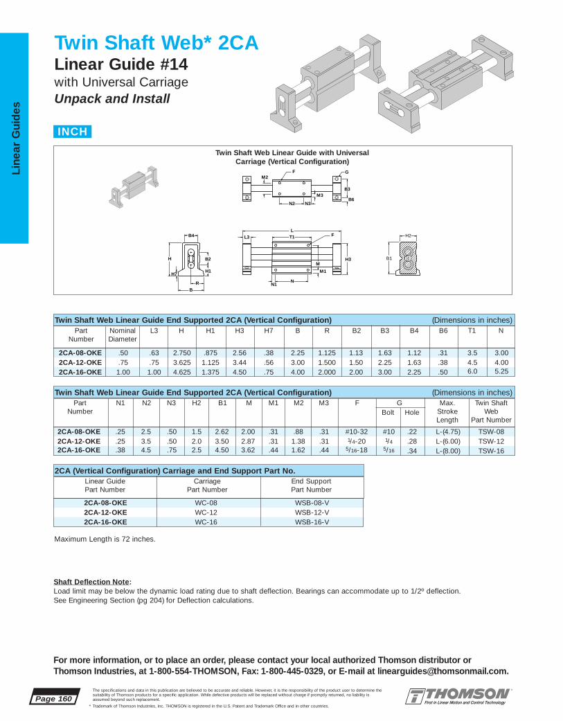
2CA-08-OKE WC-08 WSB-08-V2CA-12-OKE WC-12 WSB-12-V2CA-16-OKE WC-16 WSB-16-V
2CA-08-OKE .25 2.5 .50 1.5 2.62 2.00 .31 .88 .31 #10-32 #10 .22 L-(4.75) TSW-082CA-12-OKE .25 3.5 .50 2.0 3.50 2.87 .31 1.38 .31 1/4-20 1/4 .28 L-(6.00) TSW-122CA-16-OKE .38 4.5 .75 2.5 4.50 3.62 .44 1.62 .44 5/16-18 5/16 .34 L-(8.00) TSW-16
2CA-08-OKE .50 .63 2.750 .875 2.56 .38 2.25 1.125 1.13 1.63 1.12 .31 3.5 3.002CA-12-OKE .75 .75 3.625 1.125 3.44 .56 3.00 1.500 1.50 2.25 1.63 .38 4.5 4.002CA-16-OKE 1.00 1.00 4.625 1.375 4.50 .75 4.00 2.000 2.00 3.00 2.25 .50 6.0 5.25
Page 160The specifications and data in this publication are believed to be accurate and reliable. However, it is the responsibility of the product user to determine thesuitability of Thomson products for a specific application. While defective products will be replaced without charge if promptly returned, no liability is assumed beyond such replacement.
* Trademark of Thomson Industries, Inc. THOMSON is registered in the U.S. Patent and Trademark Office and in other countries.
Line
ar G
uid
es
For more information, or to place an order, please contact your local authorized Thomson distributor orThomson Industries, at 1-800-554-THOMSON, Fax: 1-800-445-0329, or E-mail at [email protected].
Twin Shaft Web* 2CALinear Guide #14with Universal CarriageUnpack and Install
M2
B6
F
N2
M3
N3
G
B3
LT1 F L3
N
M1
M H3
N1
B1
H2B4
H
H7
B
R
H1
B2
Twin Shaft Web Linear Guide End Supported 2CA (Vertical Configuration) (Dimensions in inches)
Twin Shaft Web Linear Guide End Supported 2CA (Vertical Configuration) (Dimensions in inches)
Part Nominal L3 H H1 H3 H7 B R B2 B3 B4 B6 T1 NNumber Diameter
Part N1 N2 N3 H2 B1 M M1 M2 M3 F G Max. Twin ShaftNumber Bolt Hole Stroke Web
Length Part Number
2CA (Vertical Configuration) Carriage and End Support Part No.Linear Guide Carriage End SupportPart Number Part Number Part Number
Twin Shaft Web Linear Guide with UniversalCarriage (Vertical Configuration)
INCH
Shaft Deflection Note:Load limit may be below the dynamic load rating due to shaft deflection. Bearings can accommodate up to 1/2º deflection. See Engineering Section (pg 204) for Deflection calculations.
Maximum Length is 72 inches.

2CA-08-OKE 290 1652CA-12-OKE 1800 13502CA-16-OKE 3000 3000
2CA-08-OME 290 1652CA-12-OME 1800 13502CA-16-OME 3000 3000
2CA-08-OME WC-08 WSB-08-H2CA-12-OME WC-12 WSB-12-H2CA-16-OME WC-16 WSB-16-H
2CA-08-OME .25 2.5 .50 1.5 2.62 2.00 .31 .88 .31 #10-32 #10 .22 L-(4.75) TSW-082CA-12-OME .25 3.5 .50 2.0 3.50 2.87 .31 1.38 .31 1/4-20 1/4 .28 L-(6.00) TSW-122CA-16-OME .38 4.5 .75 2.5 4.50 3.62 .44 1.62 .44 5/16-18 5/16 .34 L-(8.00) TSW-16
2CA-08-OME .50 .63 1.625 .875 1.5 2.62 .750 1.13 2.00 .31 3.5 3.002CA-12-OME .75 .75 2.125 1.125 2.0 3.50 1.000 1.50 2.75 .37 4.5 4.002CA-16-OME 1.00 1.00 2.625 1.375 2.5 4.50 1.250 2.00 3.62 .50 6.0 5.25
The specifications and data in this publication are believed to be accurate and reliable. However, it is the responsibility of the product user to determine thesuitability of Thomson products for a specific application. While defective products will be replaced without charge if promptly returned, no liability is assumed beyond such replacement.
* Trademark of Thomson Industries, Inc. THOMSON is registered in the U.S. Patent and Trademark Office and in other countries.
Linear Guid
es
Page 161
For more information, or to place an order, please contact your local authorized Thomson distributor orThomson Industries, at 1-800-554-THOMSON, Fax: 1-800-445-0329, or E-mail at [email protected].
Twin Shaft Web* Linear Guide 2CA Benefits:■ Used when spanning or bridging a gap.■ Double LinearRace* shaft and welded
integral web design maximizes torqueand dramatically improves deflectioncharacteristics.
■ Pre-aligned for quick and easyinstallation.
■ Designed to move medium loads withvirtually frictionless travel.
Twin Shaft Web Linear Guide 2CA Components: †■ Universal integrated, carriage with
4 open type Super Smart Ball Bushing*bearings.
■ Twin welded 60 Case* LinearRaceshafts with integral web.
■ 2 vertical or horizontal double end supports.
Specifying this Thomson Linear Guide:1. Determine the proper Linear Guide for your loadand life requirements. 2. Select the part number. 3. Add the letter “L” followed by the overall length ininches, as a suffix to the part number.
Part Numbering System
2CA-12-OME L24Linear Guide Linear GuideDesignation LengthNominal Diameter Type of Carriage
Type of Support
F G
B3M
M1
N1 N
B6
L
L2
N2
L3
H3M3
M2
N3
F
B1
H2H
B2
B
R
H1
Twin Shaft Web Linear Guide End Supported 2CA (Horizontal Configuration) (Dimensions in inches)
Twin Shaft Web Linear Guide End Supported 2CA (Horizontal Configuration) (Dimensions in inches)
Part Nominal L3 H H1 H3 B R B2 B3 B6 T1 NNumber Diameter
Part N1 N2 N3 H2 B1 M M1 M2 M3 F G Max. Twin ShaftNumber Bolt Hole Stroke Web
Length Part Number
Twin Shaft Web Linear Guide with UniversalCarriage (Horizontal Configuration)
2CA (Horizontal Configuration) Carriage and End Support Part No.Linear Guide Carriage End SupportPart Number Part Number Part Number
Dynamic Load Capacity Matrix (4 million inches travel)
Linear Guide Dynamic Load Dynamic Assembly Capacity (lbf) Roll MomentPart No. (Even Distribution) Capacity (in - lbf)
† Super Ball Bushing* bearings are used in .500 inch size carriages.
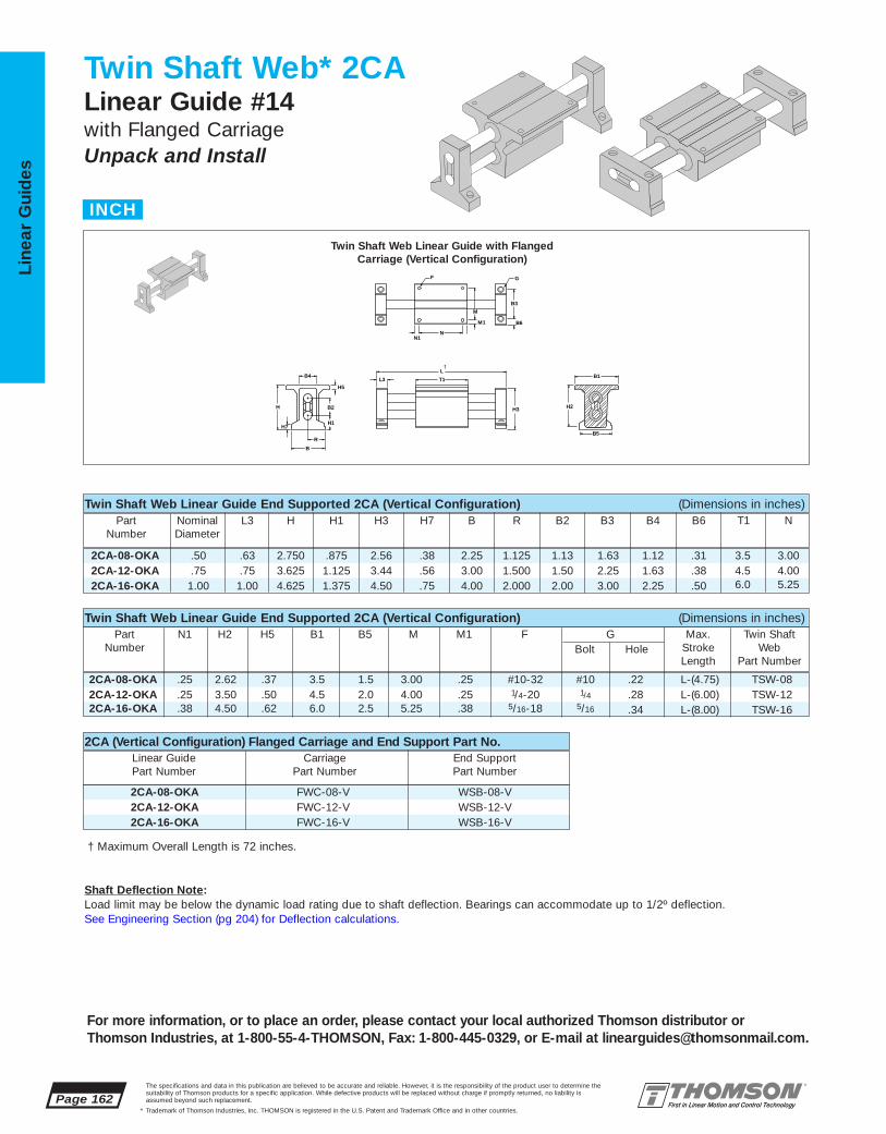
2CA-08-OKA FWC-08-V WSB-08-V2CA-12-OKA FWC-12-V WSB-12-V2CA-16-OKA FWC-16-V WSB-16-V
2CA-08-OKA .25 2.62 .37 3.5 1.5 3.00 .25 #10-32 #10 .22 L-(4.75) TSW-082CA-12-OKA .25 3.50 .50 4.5 2.0 4.00 .25 1/4-20 1/4 .28 L-(6.00) TSW-122CA-16-OKA .38 4.50 .62 6.0 2.5 5.25 .38 5/16-18 5/16 .34 L-(8.00) TSW-16
2CA-08-OKA .50 .63 2.750 .875 2.56 .38 2.25 1.125 1.13 1.63 1.12 .31 3.5 3.002CA-12-OKA .75 .75 3.625 1.125 3.44 .56 3.00 1.500 1.50 2.25 1.63 .38 4.5 4.002CA-16-OKA 1.00 1.00 4.625 1.375 4.50 .75 4.00 2.000 2.00 3.00 2.25 .50 6.0 5.25
Page 162The specifications and data in this publication are believed to be accurate and reliable. However, it is the responsibility of the product user to determine thesuitability of Thomson products for a specific application. While defective products will be replaced without charge if promptly returned, no liability is assumed beyond such replacement.
* Trademark of Thomson Industries, Inc. THOMSON is registered in the U.S. Patent and Trademark Office and in other countries.
Line
ar G
uid
es
For more information, or to place an order, please contact your local authorized Thomson distributor orThomson Industries, at 1-800-55-4-THOMSON, Fax: 1-800-445-0329, or E-mail at [email protected].
Twin Shaft Web* 2CALinear Guide #14with Flanged CarriageUnpack and Install
Twin Shaft Web Linear Guide End Supported 2CA (Vertical Configuration) (Dimensions in inches)
Twin Shaft Web Linear Guide End Supported 2CA (Vertical Configuration) (Dimensions in inches)
Part Nominal L3 H H1 H3 H7 B R B2 B3 B4 B6 T1 NNumber Diameter
Part N1 H2 H5 B1 B5 M M1 F G Max. Twin ShaftNumber Bolt Hole Stroke Web
Length Part Number
F G
B3
M
M1
N1N
B6
L
T1L3
H3 H2
B1B4
H
H7
B
R
H1
B2
B5
H5
†
Twin Shaft Web Linear Guide with FlangedCarriage (Vertical Configuration)
2CA (Vertical Configuration) Flanged Carriage and End Support Part No.Linear Guide Carriage End SupportPart Number Part Number Part Number
INCH
Shaft Deflection Note:Load limit may be below the dynamic load rating due to shaft deflection. Bearings can accommodate up to 1/2º deflection. See Engineering Section (pg 204) for Deflection calculations.
† Maximum Overall Length is 72 inches.
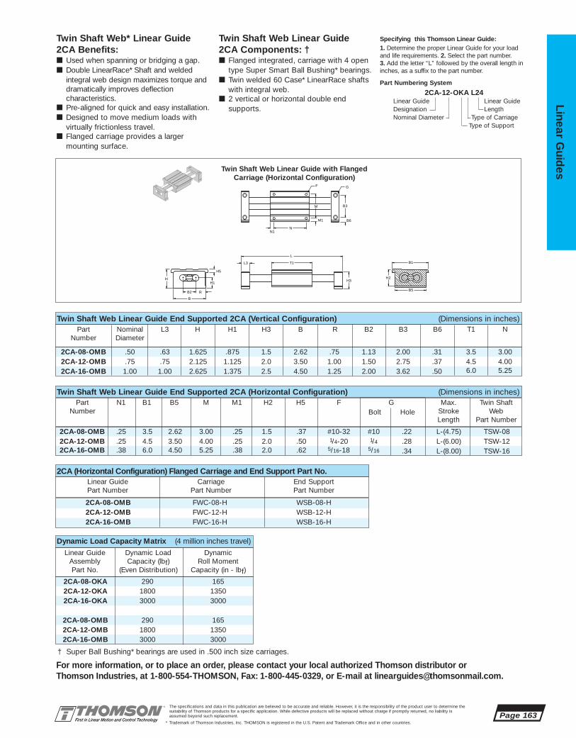
2CA-08-OKA 290 1652CA-12-OKA 1800 13502CA-16-OKA 3000 3000
2CA-08-OMB 290 1652CA-12-OMB 1800 13502CA-16-OMB 3000 3000
2CA-08-OMB FWC-08-H WSB-08-H2CA-12-OMB FWC-12-H WSB-12-H2CA-16-OMB FWC-16-H WSB-16-H
2CA-08-OMB .50 .63 1.625 .875 1.5 2.62 .75 1.13 2.00 .31 3.5 3.002CA-12-OMB .75 .75 2.125 1.125 2.0 3.50 1.00 1.50 2.75 .37 4.5 4.002CA-16-OMB 1.00 1.00 2.625 1.375 2.5 4.50 1.25 2.00 3.62 .50 6.0 5.25
2CA-08-OMB .25 3.5 2.62 3.00 .25 1.5 .37 #10-32 #10 .22 L-(4.75) TSW-082CA-12-OMB .25 4.5 3.50 4.00 .25 2.0 .50 1/4-20 1/4 .28 L-(6.00) TSW-122CA-16-OMB .38 6.0 4.50 5.25 .38 2.0 .62 5/16-18 5/16 .34 L-(8.00) TSW-16
Twin Shaft Web Linear Guide End Supported 2CA (Vertical Configuration) (Dimensions in inches)Part Nominal L3 H H1 H3 B R B2 B3 B6 T1 N
Number Diameter
The specifications and data in this publication are believed to be accurate and reliable. However, it is the responsibility of the product user to determine thesuitability of Thomson products for a specific application. While defective products will be replaced without charge if promptly returned, no liability is assumed beyond such replacement.
* Trademark of Thomson Industries, Inc. THOMSON is registered in the U.S. Patent and Trademark Office and in other countries.
Linear Guid
es
Page 163
For more information, or to place an order, please contact your local authorized Thomson distributor orThomson Industries, at 1-800-554-THOMSON, Fax: 1-800-445-0329, or E-mail at [email protected].
Twin Shaft Web* Linear Guide 2CA Benefits:■ Used when spanning or bridging a gap.■ Double LinearRace* Shaft and welded
integral web design maximizes torque anddramatically improves deflection characteristics.
■ Pre-aligned for quick and easy installation.■ Designed to move medium loads with
virtually frictionless travel.■ Flanged carriage provides a larger
mounting surface.
Twin Shaft Web Linear Guide 2CA Components: †■ Flanged integrated, carriage with 4 open
type Super Smart Ball Bushing* bearings.■ Twin welded 60 Case* LinearRace shafts
with integral web.■ 2 vertical or horizontal double end
supports.
Specifying this Thomson Linear Guide:1. Determine the proper Linear Guide for your loadand life requirements. 2. Select the part number. 3. Add the letter “L” followed by the overall length ininches, as a suffix to the part number.
Part Numbering System
2CA-12-OKA L24Linear Guide Linear GuideDesignation LengthNominal Diameter Type of Carriage
Type of Support
F G
B3M
M1
N1N
B6
L
T1L3
H3H
B2
B
R
H1
H5
B1
B5
H2
Part N1 B1 B5 M M1 H2 H5 F G Max. Twin ShaftNumber Bolt Hole Stroke Web
Length Part Number
Twin Shaft Web Linear Guide End Supported 2CA (Horizontal Configuration) (Dimensions in inches)
Twin Shaft Web Linear Guide with FlangedCarriage (Horizontal Configuration)
2CA (Horizontal Configuration) Flanged Carriage and End Support Part No.Linear Guide Carriage End SupportPart Number Part Number Part Number
Dynamic Load Capacity Matrix (4 million inches travel)
Linear Guide Dynamic Load Dynamic Assembly Capacity (lbf) Roll MomentPart No. (Even Distribution) Capacity (in - lbf)
† Super Ball Bushing* bearings are used in .500 inch size carriages.

2CA-08-OTH WC-08-SM WSB-08-VM2CA-12-OTH WC-12-SM WSB-12-VM2CA-16-OTH WC-16-SM WSB-16-VM
2CA-08-OTH 7,5 60 15 38,1 66,6 50 8,3 25 6,6 M5 M5 L-(120) TSW-082CA-12-OTH 7,5 85 15 50,8 88,9 75 7,0 35 7,9 M6 M6 L-(155) TSW-122CA-16-OTH 10 115 20 63,3 114,1 90 12,0 45 9,0 M8 M8 L-(205) TSW-16
Twin Shaft Web Linear Guide End Supported 2CA (Vertical Configuration) (Dimensions in mm)Part N1 N2 N3 H2 B1 M M1 M2 M3 F G Max. Twin Shaft
Number Stroke WebLength Part Number
2CA-08-OTH 15 70 22,5 65,0 10,6 55 27,5 28,6 41 28,6 7,5 90 752CA-12-OTH 20 92 28,4 87,3 15,4 74 36,9 38,1 56 41,3 10 115 1002CA-16-OTH 25 117 34,6 114,0 19,6 100 50,0 50,7 76 57,2 12,5 155 135
Page 164The specifications and data in this publication are believed to be accurate and reliable. However, it is the responsibility of the product user to determine thesuitability of Thomson products for a specific application. While defective products will be replaced without charge if promptly returned, no liability is assumed beyond such replacement.
* Trademark of Thomson Industries, Inc. THOMSON is registered in the U.S. Patent and Trademark Office and in other countries.
Line
ar G
uid
es
For more information, or to place an order, please contact your local authorized Thomson distributor orThomson Industries, at 1-800-55-4-THOMSON, Fax: 1-800-445-0329, or E-mail at [email protected].
M2
B6
F
N2
M3
N3
G
B3
LT1 F L3
N
M1
M H3
N1
B1
H2B4
H
H7
B
R
H1
B2
Twin Shaft Web Linear Guide End Supported 2CA (Vertical Configuration) (Dimensions in mm)Part L3 H H1 H3 H7 B R B2 B3 B4 B6 T1 N
Number
Twin Shaft Web Linear Guide with UniversalCarriage Vertical Configuration
2CA (Vertical Configuration) Carriage and End Support Part No.Linear Guide Part Number Carriage Part Number End Support Part Number
Twin Shaft Web* 2CALinear Guide #14 with Universal CarriageUnpack and Install
METRIC
Shaft Deflection Note:Load limit may be below the dynamic load rating due to shaft deflection. Bearings can accommodate up to 1/2º deflection. See Engineering Section (pg 204) for Deflection calculations.
Maximum Length is 1800 mm.

2CA-08-OTH 1290 18.52CA-12-OTH 8000 1502CA-16-OTH 13,350 3385
2CA-08-OWH 1290 18.52CA-12-OWH 8000 1502CA-16-OWH 13,350 340
2CA-08-OWH WC-08-SM WSB-08-HM2CA-12-OWH WC-12-SM WSB-12-HM2CA-16-OWH WC-16-SM WSB-16-HM
2CA-08-OWH 7,5 60 15 38,1 66,6 50 8,3 25 6,6 M5 M5 L-(120) TSW-082CA-12-OWH 7,5 85 15 50,8 88,9 75 7,0 35 7,9 M6 M6 L-(155) TSW-122CA-16-OWH 10,0 115 20 63,3 114,1 90 12,0 45 9,0 M8 M8 L-(205) TSW-16
2CA-08-OWH 15 41 21,9 37,8 65,3 18,5 28,6 50 8 90 752CA-12-OWH 20 54 28,6 50,8 88 24,5 38,1 70 8,5 115 1002CA-16-OWH 25 65 33,5 62,1 114 31,5 50,8 90 12 155 135
The specifications and data in this publication are believed to be accurate and reliable. However, it is the responsibility of the product user to determine thesuitability of Thomson products for a specific application. While defective products will be replaced without charge if promptly returned, no liability is assumed beyond such replacement.
* Trademark of Thomson Industries, Inc. THOMSON is registered in the U.S. Patent and Trademark Office and in other countries.
Linear Guid
es
Page 165
For more information, or to place an order, please contact your local authorized Thomson distributor orThomson Industries, at 1-800-554-THOMSON, Fax: 1-800-445-0329, or E-mail at [email protected].
Twin Shaft Web* Linear Guide 2CA Benefits:■ Used when spanning or bridging a gap.■ Double LinearRace* shaft and welded
integral web design maximizes torqueand dramatically improves deflectioncharacteristics.
■ Prealigned for quick and easy installation.■ Designed to move medium loads with
virtually frictionless travel.
Twin Shaft Web Linear Guide 2CA Components: †
■ Universal integrated, carriage with 4 open type Super Smart Ball Bushing*bearings.
■ Twin welded 60 Case* LinearRace shaftswith integral web.
■ 2 vertical or horizontal double end supports.
Specifying this Thomson Linear Guide:1. Determine the proper Linear Guide for your loadand life requirements. 2. Select the part number.3. Add the letter “L” followed by the overall length inmillimeters, as a suffix to the part number.
Part Numbering System
2CA-12-OWH L600Linear Guide Linear GuideDesignation LengthNominal Diameter Type of Carriage
Type of Support
F G
B3M
M1
N1 N
B6
L
L2
N2
L3
H3M3
M2
N3
F
B1
H2H
B2
B
R
H1
Twin Shaft Web Linear Guide End Supported 2CA (Horizontal Configuration) (Dimensions in mm)
Twin Shaft Web Linear Guide End Supported 2CA (Horizontal Configuration) (Dimensions in mm)
Part L3 H H1 H3 B R B2 B3 B6 T1 NNumber
Part N1 N2 N3 H2 B1 M M1 M2 M3 F G Max. Twin ShaftNumber Stroke Web
Length Part Number
Twin Shaft Web Linear Guidewith Universal CarriageHorizontal Configuration
2CA (Horizontal Configuration) Carriage and End Support Part No.Linear Guide Part Number Carriage Part Number End Support Part Number
Dynamic Load Capacity Matrix (100 km travel)Linear Guide Dynamic Load Dynamic
Assembly Capacity (N) Roll MomentPart No. (Even Distribution) Capacity (N • M)
† Super Ball Bushing* bearings are used in .500 inch size carriages.

BEL-2C-08-V 1/2 2.750 1.000 2.125 .163BEL-2C-12-V 3/4 3.750 1.125 2.375 .163BEL-2C-16-V 1 4.375 1.250 2.625 .108
BEL-2C-08-H 1/2 1.688 1.031 3.250 .108BEL-2C-12-H 3/4 2.062 1.156 3.812 .108BEL-2C-16-H 1 2.437 1.281 4.625 .108
Page 166The specifications and data in this publication are believed to be accurate and reliable. However, it is the responsibility of the product user to determine thesuitability of Thomson products for a specific application. While defective products will be replaced without charge if promptly returned, no liability is assumed beyond such replacement.
* Trademark of Thomson Industries, Inc. THOMSON is registered in the U.S. Patent and Trademark Office and in other countries.
Line
ar G
uid
es
Bellows (Way Covers) Option
Twin Shaft Web Linear Ball Guide Accessories
Note: For a Ball Screw Actuated version of a Twin Shaft Web Linear Ball Guide,see page 228 in the systems section of this catalog.
B
B1
H
H1
BEL-2C-HFor Horizontal Twin Shaft WebQuickslide* System 2CA
BEL-2C-H Moveable Protective BellowsPart Nom. Dimension (in.)
Number Shaft Dia. H H1 B
B
B1
H
H1
BEL-2C-VFor Vertical Twin Shaft WebQuickslide System 2CA
BEL-2C-V Moveable Protective BellowsPart Nom. Dimension (in.)
Number Shaft Dia. H H1 B
Each moveable bellows comes with 1 section of bellows and 2 pairs ofVelcro® Fasteners.
Each moveable bellows comes with 1 section of bellows and 2 pairs ofVelcro® Fasteners.
For more information, or to place an order, please contact your local authorized Thomson distributor orThomson Industries, at 1-800-554-THOMSON, Fax: 1-800-445-0329, or E-mail at [email protected].
CR
CR
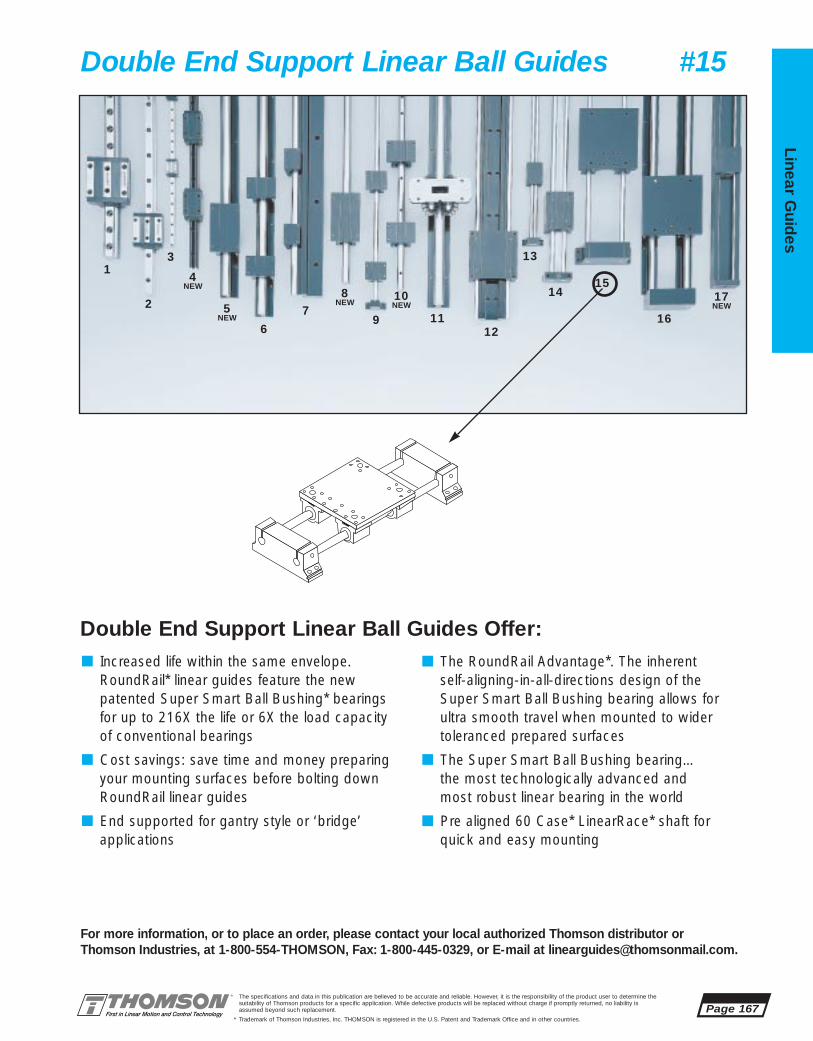
The specifications and data in this publication are believed to be accurate and reliable. However, it is the responsibility of the product user to determine thesuitability of Thomson products for a specific application. While defective products will be replaced without charge if promptly returned, no liability is assumed beyond such replacement.
* Trademark of Thomson Industries, Inc. THOMSON is registered in the U.S. Patent and Trademark Office and in other countries.
Linear Guid
es
Page 167
3
2
14
NEW
5NEW
6
79 11
12
13
1415
16
8NEW
10NEW
17NEW
For more information, or to place an order, please contact your local authorized Thomson distributor orThomson Industries, at 1-800-554-THOMSON, Fax: 1-800-445-0329, or E-mail at [email protected].
Double End Support Linear Ball Guides #15
■ Increased life within the same envelope.RoundRail* linear guides feature the new patented Super Smart Ball Bushing* bearingsfor up to 216X the life or 6X the load capacityof conventional bearings
■ Cost savings: save time and money preparingyour mounting surfaces before bolting downRoundRail linear guides
■ End supported for gantry style or ‘bridge’ applications
■ The RoundRail Advantage*. The inherent self-aligning-in-all-directions design of the Super Smart Ball Bushing bearing allows for ultra smooth travel when mounted to wider toleranced prepared surfaces
■ The Super Smart Ball Bushing bearing…the most technologically advanced and most robust linear bearing in the world
■ Pre aligned 60 Case* LinearRace* shaft forquick and easy mounting
Double End Support Linear Ball Guides Offer:

2AA-08-AXB .50 1.69 1.5 .75 .38 5.5 2.187 1.13 2.37 .38 .48 1.252AA-12-AXB .75 2.06 2.0 1.00 .50 7.5 2.937 1.50 2.70 .50 .60 1.752AA-16-AXB 1.00 2.81 2.2 1.20 .50 9.0 3.437 1.75 3.45 .50 .60 2.192AA-24-AXB 1.50 4.00 2.8 1.50 .65 13.0 5.000 2.50 5.00 .75 .81 3.25
Page 168The specifications and data in this publication are believed to be accurate and reliable. However, it is the responsibility of the product user to determine thesuitability of Thomson products for a specific application. While defective products will be replaced without charge if promptly returned, no liability is assumed beyond such replacement.
* Trademark of Thomson Industries, Inc. THOMSON is registered in the U.S. Patent and Trademark Office and in other countries.
Line
ar G
uid
es
For more information, or to place an order, please contact your local authorized Thomson distributor orThomson Industries, at 1-800-554-THOMSON, Fax: 1-800-445-0329, or E-mail at [email protected].
Double End Support 2AALinear Guide #15 with Intergrated End Supports and CarriageUnpack and Install
B6
GFN1N
M
M1
L5 L6
L
T1L1L3
H3H1
B2B
H7
H
B4 T
B3
Double End Support Linear Guide 2AA with Carriage (Dimensions in inches)Part Nominal L1 L3 L5 L6 T1 H H1 H3 H6 H7 H9
Number Diameter
INCH
Shaft Deflection Note:Load limit may be below the dynamic load rating due to shaft deflection. Bearings can accommodate up to 1/2º deflection. See Engineering Section (pg 204) for Deflection calculations.

2AA-08-AXB 800 200 13002AA-12-AXB 3600 900 81002AA-16-AXB 6000 1500 16,5002AA-24-AXB 12320 3080 57,280
2AA-08-AXB 5.3 1.025 5.5 3.25 4.8 4.25 .24 1.25 4.5 .50 3.25 1.13 1/4-20 #8 .19 L-(8.5)2AA-12-AXB 7.2 1.350 7.5 4.50 6.7 6.00 .25 1.75 6.0 .75 4.50 1.50 5/16-18 #10 .22 L-(11.50)2AA-16-AXB 8.7 1.600 9.0 5.50 8.0 7.25 .35 2.25 7.0 1.00 5.50 1.75 3/8-16 1/4 .28 L-(13.40)2AA-24-AXB 13.0 2.500 13.00 8.00 12.0 10.75 .50 3.25 10.0 1.50 8.00 2.50 1/2-13 5/16 .34 L-(18.60)
The specifications and data in this publication are believed to be accurate and reliable. However, it is the responsibility of the product user to determine thesuitability of Thomson products for a specific application. While defective products will be replaced without charge if promptly returned, no liability is assumed beyond such replacement.
* Trademark of Thomson Industries, Inc. THOMSON is registered in the U.S. Patent and Trademark Office and in other countries.
Linear Guid
es
Page 169
For more information, or to place an order, please contact your local authorized Thomson distributor orThomson Industries, at 1-800-554-THOMSON, Fax: 1-800-445-0329, or E-mail at [email protected].
R
H9
H6
C1
Double End Support Linear Guide2AA Benefits:■ Used when spanning or bridging
a gap.■ System is pre-aligned for quick and
easy installation.■ Easily adaptable to any drive system.■ Single part number is all that is
required to specify.
Double End Support Linear Guide2AA Components: †■ 4 Super Smart Ball Bushing*
pillow blocks.■ 2 60 Case* LinearRace* shafts.■ 2 integrated double end supports.■ 1 mounting carriage top.
Specifying this Thomson Linear Guide:
1. Determine the proper Linear Guide for your loadand life requirements. 2. Select the part number. 3. Add the letter “L” followed by the overall length ininches, as a suffix to the part number.
Part Numbering System
2AA-12-AXB L24Linear Guide Linear GuideDesignation LengthNominal Diameter Type of Carriage
Type of Bearing Block Type of Support
Double End Support Linear Guide 2AA with Carriage (Dimensions in inches)Part B R T B2 B3 B4 B6 C1 N N1 M M1 F G Max.
Number Bolt Hole StrokeLength
Carriage Cross Section
Dynamic Load Capacity Matrix (4 million inches travel)Linear Guide Dynamic Load Pillow Block Dynamic
Assembly Capacity (lbf) Dynamic Load Roll Moment Part No. (Even Distribution) Capacity (lbf) Capacity (in - lbf)
† Super Ball Bushing* bearings are used in .500 inch size carriages.

BEL-2AE-08 1/2 1.400 1.240 5.250 .163BEL-2AE-12 3/4 2.098 1.348 6.850 .163BEL-2AE-16 1 2.800 1.675 8.100 .163BEL-2AE-24 11/2 4.200 2.435 11.180 .163
Page 170The specifications and data in this publication are believed to be accurate and reliable. However, it is the responsibility of the product user to determine thesuitability of Thomson products for a specific application. While defective products will be replaced without charge if promptly returned, no liability is assumed beyond such replacement.
* Trademark of Thomson Industries, Inc. THOMSON is registered in the U.S. Patent and Trademark Office and in other countries.
Line
ar G
uid
es
For more information, or to place an order, please contact your local authorized Thomson distributor orThomson Industries, at 1-800-554-THOMSON, Fax: 1-800-445-0329, or E-mail at [email protected].
Bellows (Way Covers) Option
Double End Support Linear Ball Guide Accessories
Note: For a Ball Screw Actuated version of a Double End Support Linear Ball Guide, see page 224 in the systems section of this catalog.
BEL-2AEFor QuickSlide* Systems 2AA, 2EA and SuperSlide* Systems 2AB, 2EB
BEL-2AE Moveable Protective BellowsPart Nom. Dimension (in.)
Number Shaft Dia. H H1 B
B
H
H1
CR

The specifications and data in this publication are believed to be accurate and reliable. However, it is the responsibility of the product user to determine thesuitability of Thomson products for a specific application. While defective products will be replaced without charge if promptly returned, no liability is assumed beyond such replacement.
* Trademark of Thomson Industries, Inc. THOMSON is registered in the U.S. Patent and Trademark Office and in other countries.
Linear Guid
es
Page 171
3
2
1 4NEW
5NEW
6
79 11
12
13
14
15
16
8NEW 10
NEW17NEW
For more information, or to place an order, please contact your local authorized Thomson distributor orThomson Industries, at 1-800-554-THOMSON, Fax: 1-800-445-0329, or E-mail at [email protected].
Double Continuous Support Linear Ball Guides #16
■ Increased life within the same envelope.RoundRail* linear guides feature the new patented Super Smart Ball Bushing* bearingsfor up to 216X the life or 6X the load capacityof conventional bearings
■ Maximum performance. Fully supported for maximum (multidirectional) load applications without concerns for shaft deflection
■ The RoundRail Advantage*. The inherent self-aligning-in-all-directions design of the Super Smart Ball Bushing bearing allows for ultra smooth travel when mounted to wider toleranced prepared surfaces
■ Unlimited travel lengths without concerns for machined reference edges or butt joint alignment
■ The Super Smart Ball Bushing bearing…themost technologically advanced and mostrobust linear bearing in the world
■ Pre aligned 60 Case* LinearRace* shaft forquick and easy mounting
■ Cost savings: save time and money preparingyour mounting surfaces before bolting downRoundRail linear guides.
Double Continuous Support Linear Ball Guides Offer:

2EA-08-FAB .50 1.50 1.5 5.5 1.00 2.187 1.13 2.38 .38 .19 1.122EA-12-FAB .75 1.88 2.0 7.5 1.25 2.937 1.50 2.75 .50 .25 1.562EA-16-FAB 1.00 2.63 2.2 9.0 1.50 3.437 1.75 3.37 .50 .25 2.002EA-24-FAB 1.50 3.75 2.8 13.0 2.25 5.000 2.50 4.87 .75 .30 2.94
Page 172The specifications and data in this publication are believed to be accurate and reliable. However, it is the responsibility of the product user to determine thesuitability of Thomson products for a specific application. While defective products will be replaced without charge if promptly returned, no liability is assumed beyond such replacement.
* Trademark of Thomson Industries, Inc. THOMSON is registered in the U.S. Patent and Trademark Office and in other countries.
Line
ar G
uid
es
For more information, or to place an order, please contact your local authorized Thomson distributor orThomson Industries, at 1-800-554-THOMSON, Fax: 1-800-445-0329, or E-mail at [email protected].
TB4
H
B2
B
H1H3
L3 L1
T1
N
F M1
M
K
GN1N
XY
Double Continuously Supported Linear Guide 2EA with Carriage (Dimensions in inches)Part Nominal L1 L3 T1 K H H1 H3 H6 H7 H9
Number Diameter
Maximum continuous length of support rails is 24”. If longer continuous shaft support rails are required, please contact the Thomson Linear Guides Application Engineering department.
INCH
Double Continuous Support 2EALinear Guide #16 with Integrated End Supports and CarriageUnpack and Install
FcFtFs
C0.5C
C
C0.5C0.5C
DynamicLoad Rating Load Limit
Load Rating andLimit by Direction
Fc Ft
Fs
Dynamic Load RatingLoad value used in life calculation.Load LimitMaximum allowable load applied to bearing.
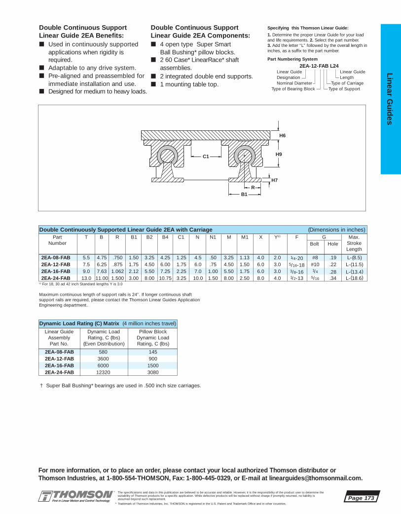
2EA-08-FAB 580 1452EA-12-FAB 3600 9002EA-16-FAB 6000 15002EA-24-FAB 12320 3080
2EA-08-FAB 5.5 4.75 .750 1.50 3.25 4.25 1.25 4.5 .50 3.25 1.13 4.0 2.0 1/4-20 #8 .19 L-(8.5)2EA-12-FAB 7.5 6.25 .875 1.75 4.50 6.00 1.75 6.0 .75 4.50 1.50 6.0 3.0 5/16-18 #10 .22 L-(11.5)2EA-16-FAB 9.0 7.63 1.062 2.12 5.50 7.25 2.25 7.0 1.00 5.50 1.75 6.0 3.0 3/8-16 1/4 .28 L-(13.4)2EA-24-FAB 13.0 11.00 1.500 3.00 8.00 10.75 3.25 10.0 1.50 8.00 2.50 8.0 4.0 1/2-13 5/16 .34 L-(18.6)
The specifications and data in this publication are believed to be accurate and reliable. However, it is the responsibility of the product user to determine thesuitability of Thomson products for a specific application. While defective products will be replaced without charge if promptly returned, no liability is assumed beyond such replacement.
* Trademark of Thomson Industries, Inc. THOMSON is registered in the U.S. Patent and Trademark Office and in other countries.
Linear Guid
es
Page 173
For more information, or to place an order, please contact your local authorized Thomson distributor orThomson Industries, at 1-800-554-THOMSON, Fax: 1-800-445-0329, or E-mail at [email protected].
Double Continuous SupportLinear Guide 2EA Benefits:■ Used in continuously supported
applications when rigidity is required.
■ Adaptable to any drive system.■ Pre-aligned and preassembled for
immediate installation and use.■ Designed for medium to heavy loads.
Double Continuous SupportLinear Guide 2EA Components:■ 4 open type Super Smart
Ball Bushing* pillow blocks.■ 2 60 Case* LinearRace* shaft
assemblies.■ 2 integrated double end supports.■ 1 mounting table top.
Specifying this Thomson Linear Guide:
1. Determine the proper Linear Guide for your loadand life requirements. 2. Select the part number. 3. Add the letter “L” followed by the overall length ininches, as a suffix to the part number.
Part Numbering System
2EA-12-FAB L24Linear Guide Linear GuideDesignation LengthNominal Diameter Type of Carriage
Type of Bearing Block Type of Support
R
H9
H6
C1
B1
H7
Double Continuously Supported Linear Guide 2EA with Carriage (Dimensions in inches)Part T B R B1 B2 B4 C1 N N1 M M1 X Y(1) F G Max.
Number Bolt Hole StrokeLength
(1) For 18, 30 ad 42 inch Standard lengths Y is 3.0
Maximum continuous length of support rails is 24”. If longer continuous shaft support rails are required, please contact the Thomson Linear Guides Application Engineering department.
Dynamic Load Rating (C) Matrix (4 million inches travel)
Linear Guide Dynamic Load Pillow BlockAssembly Rating, C (lbs) Dynamic Load Part No. (Even Distribution) Rating, C (lbs)
† Super Ball Bushing* bearings are used in .500 inch size carriages.
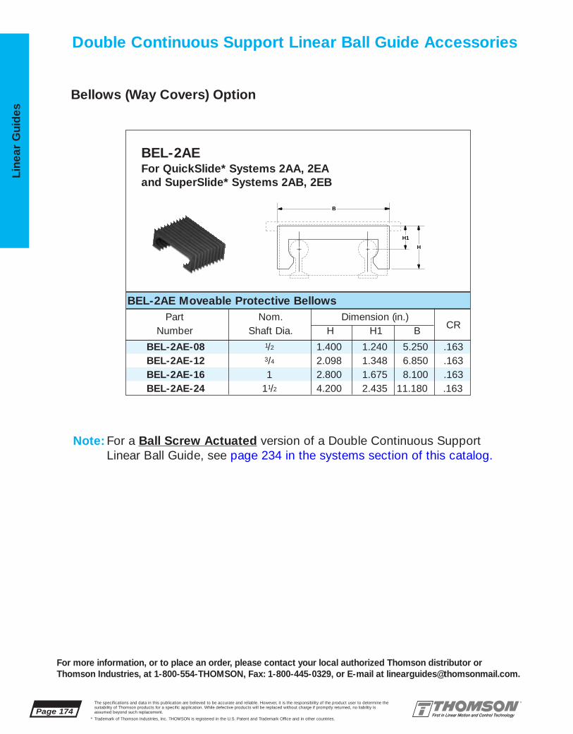
Page 174The specifications and data in this publication are believed to be accurate and reliable. However, it is the responsibility of the product user to determine thesuitability of Thomson products for a specific application. While defective products will be replaced without charge if promptly returned, no liability is assumed beyond such replacement.
* Trademark of Thomson Industries, Inc. THOMSON is registered in the U.S. Patent and Trademark Office and in other countries.
Line
ar G
uid
es
For more information, or to place an order, please contact your local authorized Thomson distributor orThomson Industries, at 1-800-554-THOMSON, Fax: 1-800-445-0329, or E-mail at [email protected].
Bellows (Way Covers) Option
Double Continuous Support Linear Ball Guide Accessories
Note: For a Ball Screw Actuated version of a Double Continuous Support Linear Ball Guide, see page 234 in the systems section of this catalog.
BEL-2AE-08 1/2 1.400 1.240 5.250 .163BEL-2AE-12 3/4 2.098 1.348 6.850 .163BEL-2AE-16 1 2.800 1.675 8.100 .163BEL-2AE-24 11/2 4.200 2.435 11.180 .163
BEL-2AEFor QuickSlide* Systems 2AA, 2EA and SuperSlide* Systems 2AB, 2EB
BEL-2AE Moveable Protective BellowsPart Nom. Dimension (in.)
Number Shaft Dia. H H1 B
B
H
H1
CR

The specifications and data in this publication are believed to be accurate and reliable. However, it is the responsibility of the product user to determine thesuitability of Thomson products for a specific application. While defective products will be replaced without charge if promptly returned, no liability is assumed beyond such replacement.
* Trademark of Thomson Industries, Inc. THOMSON is registered in the U.S. Patent and Trademark Office and in other countries.
Linear Guid
es
Page 175
MicroStage Linear Ball Guides #17
■ Smooth precision Linear Motion. ThomsonMicroStage linear guide features unique bear-ing segment design and offers a backlash freeslide assembly without sacrificing load capaci-ty or smoothness.
■ Rugged but light-weight MicroStage linearguides are manufactured from aerospace alloysproviding the optimum in strength and rigidity,while dramatically decreasing the mass of thesystem. This provides for lower inertia andhigher performance than either built-in, orexternal actuators.
■ Flexible mounting configuration. MicroStagelinear guides offer hole patterns and T-slotsthat allow them to be easily interchanged andalso provide simple X-Y mounting.
MicroStage* Linear Guides Offer:
NEW
For more information, or to place an order, please contact your local authorized Thomson distributor orThomson Industries, at 1-800-554-THOMSON, Fax: 1-800-445-0329, or E-mail at [email protected].
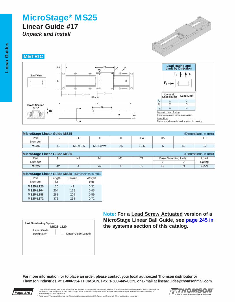
Page 176The specifications and data in this publication are believed to be accurate and reliable. However, it is the responsibility of the product user to determine thesuitability of Thomson products for a specific application. While defective products will be replaced without charge if promptly returned, no liability is assumed beyond such replacement.
* Trademark of Thomson Industries, Inc. THOMSON is registered in the U.S. Patent and Trademark Office and in other countries.
Line
ar G
uid
es
For more information, or to place an order, please contact your local authorized Thomson distributor orThomson Industries, at 1-800-554-THOMSON, Fax: 1-800-445-0329, or E-mail at [email protected].
MicroStage* MS25Linear Guide #17 Unpack and Install
Part Numbering SystemMS25-L120
Linear GuideDesignation Linear Guide Length
L
T1
H
A
A
H4
H5
Cross Section A – A
B K
Y XN 1
L 3
M
M 1F GT 1
N
MicroStage Linear Guide MS25 (Dimensions in mm)Part B F G H H4 H5 K L3
NumberMS25 50 M3 x 0,5 M3 Screw 25 18,6 6 42 12
MicroStage Linear Guide MS25 (Dimensions in mm)Part N N1 M M1 T1 Base Mounting Hole Load
Number X Y RatingMS25 42 4 42 4 55 42 39 425N
MicroStage Linear Guide MS25 (Dimensions in mm)Part Length Stroke Weight
Number (L) (kg)
MS25-L120 120 41 0,31MS25-L204 204 125 0,45MS25-L288 288 209 0,59MS25-L372 372 293 0,72
METRIC
End View
FcFtFs
CCC
CCC
DynamicLoad Rating Load Limit
Load Rating andLimit by Direction
Fc Ft
Fs
Dynamic Load RatingLoad value used in life calculation.Load LimitMaximum allowable load applied to bearing.
Note: For a Lead Screw Actuated version of aMicroStage Linear Ball Guide, see page 245 inthe systems section of this catalog.

The specifications and data in this publication are believed to be accurate and reliable. However, it is the responsibility of the product user to determine thesuitability of Thomson products for a specific application. While defective products will be replaced without charge if promptly returned, no liability is assumed beyond such replacement.
* Trademark of Thomson Industries, Inc. THOMSON is registered in the U.S. Patent and Trademark Office and in other countries.
Linear Guid
es
Page 177
For more information, or to place an order, please contact your local authorized Thomson distributor orThomson Industries, at 1-800-554-THOMSON, Fax: 1-800-445-0329, or E-mail at [email protected].
MicroStage* MS33Linear Guide #17 Unpack and Install
Part Numbering System
MS33-L200Linear Guide Designation Linear Guide Length
L
T1Cross Section
A – A
H4H
H5 A
A
T-slots
D2
D3D4
D1
B K
Y X NN 1
M
M 1
F GT 1L 3
MicroStage Linear Guide MS33 (Dimensions in mm)Part B D1 D2 D3 D4 F G H H4 H5
Number
MS33 60 8,0 4,2 2,75 2 M5 x 0,8 M5 Screw 33 25,5 7
MicroStage Linear Guide MS33 (Dimensions in mm)Part K L3 N N1 M M1 T1 Base Mounting Hole Load
Number X Y RatingMS33 30 13 30 15 30 15 65 100 50 850N
MicroStage Linear Guide MS33 (Dimensions in mm)Part Length Stroke Weight
Number (L) (kg)
MS33-L200 200 109 0,74MS33-L300 300 209 1,00MS33-L400 400 309 1,27
METRIC
End View
FcFtFs
CCC
CCC
DynamicLoad Rating Load Limit
Load Rating andLimit by Direction
Fc Ft
Fs
Dynamic Load RatingLoad value used in life calculation.Load LimitMaximum allowable load applied to bearing.
Note: For a Lead Screw Actuated version of aMicroStage Linear Ball Guide, see page 245 inthe systems section of this catalog.

Installation Guidelines for :
Linear Guides #1 – 4 Pages 179 – 182
Linear Guides #5 – 11 Pages 183– 184
Linear Guides #12 – 17 Page 184
Page 178The specifications and data in this publication are believed to be accurate and reliable. However, it is the responsibility of the product user to determine thesuitability of Thomson products for a specific application. While defective products will be replaced without charge if promptly returned, no liability is assumed beyond such replacement.
* Trademark of Thomson Industries, Inc. THOMSON is registered in the U.S. Patent and Trademark Office and in other countries.
Line
ar G
uid
es
For more information, or to place an order, please contact your local authorized Thomson distributor orThomson Industries, at 1-800-554-THOMSON, Fax: 1-800-445-0329, or E-mail at [email protected].
Installation Guidelines
3
2
1 4NEW
5NEW
6
79 11
12
13
1415
16
8NEW 10
NEW 17NEW

The specifications and data in this publication are believed to be accurate and reliable. However, it is the responsibility of the product user to determine thesuitability of Thomson products for a specific application. While defective products will be replaced without charge if promptly returned, no liability is assumed beyond such replacement.
* Trademark of Thomson Industries, Inc. THOMSON is registered in the U.S. Patent and Trademark Office and in other countries.
Linear Guid
es
For more information, or to place an order, please contact your local authorized Thomson distributor orThomson Industries, at 1-800-55-4-THOMSON, Fax: 1-800-445-0329, or E-mail at [email protected].
Installation Guidelines for Linear Guides #1–4Surface Preparation ProfileRail* bearings are generally mounted to structures thatare inherently stiffer than the rail. For this reason, the bearingstend to assume the orientation of the surfaces to which theyare fastened, through bearing deflection. When a deflection isimposed upon a bearing, especially a preloaded one, resultantforces occur. These forces are applied to the rolling elementsand races, causing an increase in system friction and adecrease in system resolution, precision and life.
Various sources contribute to the overall error of the mountingsurfaces. These include the surface flatness of the base surfaces, the location and parallelism of the reference surfaces, and the attendant errors of the bearing as describedwithin the accuracy classes.
The surfaces that contact the base and reference edges maybe milled, scraped, ground, or prepared by any other methodthat will produce a flat surface free of inconsistencies, whichwill tend to distort or skew the bearing. A simple stone maybe used to remove high spots. Dirt and debris also contributeto the inaccuracies.
Associated with preload is a slight concavity of the carriagetop surface. The preload is established when all the carriage screws are affixed to a planar surface, flattening thecarriage base. Deviations from planarity of the carriage mounting surface will result in a preload change.
Mounting TolerancesThe tolerances found in Tables 1-3 are intended to yieldan installation for which the associated derating is negligible. These specifications are based upon theassumption that the structures of the application are infinitely rigid and are based upon the bearing reactionsonly.
Rail ParallelismA variation in the distance between the rails will induce a shear or side load on the bearings.
Figure 1
In order to reduce the effect of this shear load, tolerancesfor rail reference edge parallelism may be found in Table 1.
Table 1. Parallelism Between Multiple Rails, mm
†Where C=Dynamic Load Capacity
PreloadBearing Type Clearance 0,03 C† 0,08 C† 0,13 C†
AccuMax* linear guide
35 – 0,008 0,005 0,003
45 – 0,010 0,007 0,004
55 – 0,012 0,008 0,005
65 – 0,014 0,010 0,007
AccuGlide* linear guide
20 0,016 0,011 0,007 0,005
25 0,017 0,012 0,008 0,005
30 0,021 0,014 0,009 0,006
35 0,023 0,015 0,010 0,007
45 0,027 0,018 0,012 0,008
55 0,035 0,024 0,015 0,011
AccuGlide Miniature linear guide
10 0,009 0,004 – –
15 0,011 0,006 – –
20 0,013 0,008 – –
AccuGlide T-Series* linear guide
20 – 0,045 – –25 – 0,050 – –30 – 0,055 – –35 – 0,060 – –
P1
Page 179
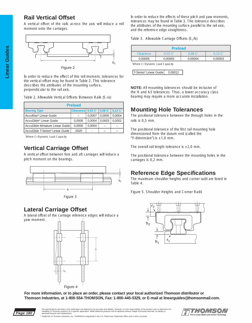
Page 180The specifications and data in this publication are believed to be accurate and reliable. However, it is the responsibility of the product user to determine thesuitability of Thomson products for a specific application. While defective products will be replaced without charge if promptly returned, no liability is assumed beyond such replacement.
* Trademark of Thomson Industries, Inc. THOMSON is registered in the U.S. Patent and Trademark Office and in other countries.
Line
ar G
uid
es
For more information, or to place an order, please contact your local authorized Thomson distributor orThomson Industries, at 1-800-554-THOMSON, Fax: 1-800-445-0329, or E-mail at [email protected].
Rail Vertical OffsetA vertical offset of the rails across the axis will induce a rollmoment onto the carriages.
In order to reduce the effect of this roll moment, tolerances forthe vertical offset may be found in Table 2. This tolerancedescribes the attributes of the mounting surface, perpendicular to the rail axis.
Table 2. Allowable Vertical Offsets Between Rails (S1/a)
Vertical Carriage OffsetA vertical offset between fore and aft carriages will induce apitch moment on the bearings.
Figure 3
Lateral Carriage OffsetA lateral offset of the carriage reference edges will induce ayaw moment.
In order to reduce the effects of these pitch and yaw moments,tolerances may be found in Table 3. This tolerance describesthe attributes of the mounting surface parallel to the rail axis,and the reference edge straightness.
Table 3. Allowable Carriage Offsets (S2/b)
NOTE: All mounting tolerances should be inclusive of the H and A3 tolerances. Thus, a lower accuracy class bearing may require a more accurate installation.
Mounting Hole TolerancesThe positional tolerance between the through holes in the rails is 0,5 mm.
The positional tolerance of the first rail mounting holedimensioned from the datum end (called the “Y-dimension”) is ±1,0 mm.
The overall rail length tolerance is ±2,0 mm.
The positional tolerance between the mounting holes in thecarriages is 0,2 mm.
Reference Edge SpecificationsThe maximum shoulder heights and corner radii are listed inTable 4.
Figure 5. Shoulder Heights and Corner Radii
†Where C=Dynamic Load Capacity
†Where C=Dynamic Load Capacity
PreloadBearing Type Clearance 0,03 C† 0,08 C† 0,13 C†
AccuMax* Linear Guide – 0,0007 0,0005 0,0004
AccuGlide* Linear Guide 0,0006 0,0004 0,0003 0,0002
AccuGlide Miniature Linear Guide 0,0006 0,0004 – –
AccuGlide T-Series* Linear Guide .0020 - – –
PreloadClearance 0,03 C† 0,08 C† 0,13 C†
0,00006 0,00005 0,00004 0,00003
T-Series* Linear Guide 0,00012
S2
b
b
S2
h1r1
r2
h2
aS1
Figure 2
Figure 4

The specifications and data in this publication are believed to be accurate and reliable. However, it is the responsibility of the product user to determine thesuitability of Thomson products for a specific application. While defective products will be replaced without charge if promptly returned, no liability is assumed beyond such replacement.
* Trademark of Thomson Industries, Inc. THOMSON is registered in the U.S. Patent and Trademark Office and in other countries.
Linear Guid
es
For more information, or to place an order, please contact your local authorized Thomson distributor orThomson Industries, at 1-800-554-THOMSON, Fax: 1-800-445-0329, or E-mail at [email protected].
Table 4. Shoulder heights and corner radii, mm
Installation ProcedureClean and inspect all mating surfaces for burrs, nicks, dirt,etc. A simple stone can be used to remove minor imperfections in the mounting surfaces.
Recommended Bolt Tightening Torque, Nm
Table 5
Rail Mounting1. Carefully place the rail on the mounting surface.
2. Insert screws into the mounting holes and tighten lightly.
3. Clamp the reference edge of the rail against a locatingedge on the mounting surface.
The locating edge can be a machined reference edge, astraight edge, a row of dowels or keys, or some other edgewhich the rail can be clamped against. It should be straight,either within the mounting tolerances shown in Table 3 oraccording to the application requirements, whichever istighter.
4. Starting from the center of the rail, tighten each screw tothe recommended tightening torque in Table 5.
5. If parallel rails are to be used, one of the following methodsmay be employed to obtain the parallelism recommended inTable 1.
a. 2 parallel locating edgesb. a gage block or parallel between the railsc. the use of the top plate with the carriages
mounted, to locate or “float” the second rail intoplace.
6. Repeat steps 1-4 to install the second rail.
7. Insert a rail plug into each counterbore in the rail. Carefullytap rail plugs into place using a soft material such as brass orwood. When properly installed, the rail plugs should be flushwith the top surface of the rail. Do not countersink the railplugs.
Note: Rail plugs are available and are shipped with all railsexcept for the AccuGlide* Miniature Linear Guide size 10.
8. If desired, rail tape can then be applied to the top of therail. For sizes 35 and below, the rail tape may be used without the rail plugs.
Guide Type Rail Carriageh1 max r1 max h2 r2 max
AccuMax* linear guide
30 4 0,8 6 0,5
35 5 0,8 8 0,8
45 6,5 1 9 1
55 7 1,2 10 1,2
65 9 1,5 12 1,2
AccuGlide* linear guide
20 4 0,5 8 0,4
25 5,5 0,8 10 0,4
30 5,25 0,8 12 0,6
35 6 0,8 14 0,6
45 8,25 1,2 18 0,9
55 11 1,2 22 1,2
AccuGlide Miniature linear guide
10 1,75 0,4 3,5 0,415 1,75 0,4 5 0,420 2 0,5 7 0,5
AccuGlide T-Series* linear guide
20 3,9 0,4 10 0,325 5,5 0,5 12 0,430 5,9 0,7 14 0,535 5,9 0,8 15 0,6
Bolt Size Class 8.8 Class 12.9
M2.5 0,7 1,2
M4 2,8 4,6
M5 5,7 9,5
M6 9,5 16
M8 23 39
M10 46 77
M12 80 135
M14 129 215
M16 198 330
Page 181

Page 182The specifications and data in this publication are believed to be accurate and reliable. However, it is the responsibility of the product user to determine thesuitability of Thomson products for a specific application. While defective products will be replaced without charge if promptly returned, no liability is assumed beyond such replacement.
* Trademark of Thomson Industries, Inc. THOMSON is registered in the U.S. Patent and Trademark Office and in other countries.
Line
ar G
uid
es
For more information, or to place an order, please contact your local authorized Thomson distributor orThomson Industries, at 1-800-554-THOMSON, Fax: 1-800-445-0329, or E-mail at [email protected].
Butt JointsFor rails longer than the longest length available in onepiece, a butt joint is required. A butt joint is formed bybutting the end of two matched rails together. The ends ofrails to be butt jointed are specially machined and markedwith same letter (A, B, C, etc.).
We strongly recommend the use of a locating edge whenusing butt jointed rails. This will ensure proper alignment ofthe raceways across the joint.
For AccuGlide* and AccuGlide Miniature linear guide rails, themounting hole spacing across the joint, Z, will be 1/2 thestandard mounting hole spacing, X. For AccuMax* linearguide rails, the mounting hole spacing across the joint, Z, willbe equal to the standard mounting hole spacing, X.
Figure 6. Butt jointed rails
Once mounted, a gap between the ends of the butt jointedrails of 0,5 mm or less is acceptable.
Carriage Mounting1. Carefully place the table top on the carriages.
2. Insert the screws into the mounting holes and tighten lightly.
3. Clamp the reference edge of the carriages to locating edges under the top plate.
Note: This is only required if the location of the center of thetop plate is critical to the application, or if the top plate isbeing used to position a second rail parallel.
4. Tighten each screw to the recommended tighteningtorque in Table 5. For carriages with six mounting screws,the tightening sequence shown in Figure 7 is recommended.
Figure 7. Recommended Tightening Sequence
5. Lubricate bearings.
Note: Extreme care should be taken when mounting the carriages to the rails. Forcing a carriage onto a rail canknock out rolling elements and/or damage the carriage and rail.
For large side forces, hard mounting is recommended toresist any translation. Some methods for hard mounting arethe use of tapered gibs, retaining plates, or set screws incombination with machined reference edges. Other methodsinclude the use of an epoxy/replicating material, dowels, andkeys. Upon request, carriages and rails can be specialmachined to accommodate dowels or keys. Consult the factory for details.
ZA A
Reference EdgeJoint
Joint Indicator X(TYP)
1
3 4
5 6
2
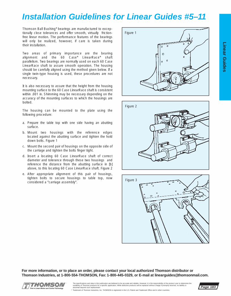
The specifications and data in this publication are believed to be accurate and reliable. However, it is the responsibility of the product user to determine thesuitability of Thomson products for a specific application. While defective products will be replaced without charge if promptly returned, no liability is assumed beyond such replacement.
* Trademark of Thomson Industries, Inc. THOMSON is registered in the U.S. Patent and Trademark Office and in other countries.
Linear Guid
es
For more information, or to place an order, please contact your local authorized Thomson distributor orThomson Industries, at 1-800-554-THOMSON, Fax: 1-800-445-0329, or E-mail at [email protected].
Thomson Ball Bushing* bearings are manufactured to excep-tionally close tolerances and offer smooth, virtually friction-free linear motion. The performance features of the bearingswill only be realized, however, if care is taken during their installation.
Two areas of primary importance are the bearingalignment and the 60 Case* LinearRace* shaft parallelism. Two bearings are normally used on each 60 CaseLinearRace shaft to assure smooth operation. The housingshould be carefully aligned using the method given below. If asingle twin-type housing is used, these procedures are notnecessary.
It is also necessary to assure that the height from the housingmounting surface to the 60 Case LinearRace shaft is consistentwithin .001 in. Shimming may be necessary depending on theaccuracy of the mounting surfaces to which the housings arebolted.
The housing can be mounted to the plate using the following procedure:
a. Prepare the table top with one side having an abutting surface.
b. Mount two housings with the reference edges located against the abutting surface and tighten the holddown bolts. Figure 1
c. Mount the second pair of housings on the opposite side ofthe carriage and tighten the bolts finger tight.
d. Insert a locating 60 Case LinearRace shaft of correct diameter and tolerance through these two housings andreference the distance from the abutting surface in [b]above, to this locating 60 Case LinearRace shaft. Figure 2
e. After appropriate alignment of this pair of housings, tighten bolts to secure housings to table top, now considered a “carriage assembly”.
Figure 1
Figure 2
Figure 3
Installation Guidelines for Linear Guides #5–11
Page 183

Page 184The specifications and data in this publication are believed to be accurate and reliable. However, it is the responsibility of the product user to determine thesuitability of Thomson products for a specific application. While defective products will be replaced without charge if promptly returned, no liability is assumed beyond such replacement.
* Trademark of Thomson Industries, Inc. THOMSON is registered in the U.S. Patent and Trademark Office and in other countries.
Line
ar G
uid
es
For more information, or to place an order, please contact your local authorized Thomson distributor orThomson Industries, at 1-800-554-THOMSON, Fax: 1-800-445-0329, or E-mail at [email protected].
After the carriage assembly is properly prepared, the 60 Case*LinearRace* shaft must be mounted to the surface. To achievesmooth, accurate motion, the 60 Case LinearRace shaft mustbe mounted parallel within .001 inch over the length of thestroke. This can be done by using the following procedure:
a. Mount one 60 Case LinearRace shaft (either end supported or continuously supported) to the surface withmounting bolts finger tight.
b. Using an aligning device such as a laser, auto-collimator or other optics, sight the 60 Case LinearRaceshaft straight to .002”/ft or less and secure to mountingsurface.
c. After this first 60 Case LinearRace shaft is fixed, the second 60 Case LinearRace shaft can be positioned andheld down with bolts finger tight.
d. The carriage assembly is then mounted and its movementwill pull this second 60 Case LinearRace shaft parallel tothe first. Figures 3, 4
e. If the second 60 Case LinearRace shaft is then securedinto position, the procedure is complete. Note that for continuously supported systems, this securing should bedone when the carriage is close to the bolts. For end supported systems, the securing should be done whenthe carriage is at the ends of the 60 Case LinearRaceshaft. Figure 5
f. An additional check can be done at this time to assure thatthe carriage assembly is tracking correctly (i.e., that thecarriage assembly edge is moving parallel to the 60 CaseLinearRace shaft). An indicator touching the carriageassembly edge should not vary, as the carriage assemblyis moved along the 60 Case LinearRace shaft. Figure 6
Figure 4
Figure 5
Figure 6
1 Remove linear guide from shipping package.
2 Fasten linear guide to mounting surface.
Installation Guidelines for Linear Guides #12–17

The specifications and data in this publication are believed to be accurate and reliable. However, it is the responsibility of the product user to determine thesuitability of Thomson products for a specific application. While defective products will be replaced without charge if promptly returned, no liability is assumed beyond such replacement.
* Trademark of Thomson Industries, Inc. THOMSON is registered in the U.S. Patent and Trademark Office and in other countries.
Linear Guid
esE
ngineering
Sup
po
rt
Page 185
• Linear Guide Selection
• Technology Overview
• Sizing & Defining Guide Characteristics
• Applied Loading Calculations
• Load Ratings: Rolling Element Guides Sliding Contact Guides
• Preloading & Linear Guide Deflection
• Accuracy Class
• Actuation Force
• Lubrication
• Way Cover Length Calculations
• Butt Joint fax-back Worksheet
• Conversion Table
Linear Guide Engineering Section
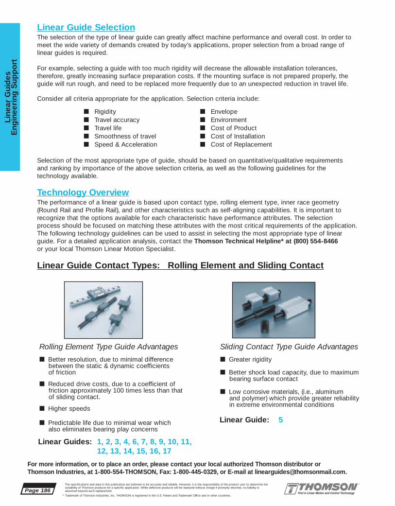
Page 186The specifications and data in this publication are believed to be accurate and reliable. However, it is the responsibility of the product user to determine thesuitability of Thomson products for a specific application. While defective products will be replaced without charge if promptly returned, no liability is assumed beyond such replacement.
* Trademark of Thomson Industries, Inc. THOMSON is registered in the U.S. Patent and Trademark Office and in other countries.
Line
ar G
uid
esE
ngin
eeri
ng S
upp
ort
For more information, or to place an order, please contact your local authorized Thomson distributor orThomson Industries, at 1-800-554-THOMSON, Fax: 1-800-445-0329, or E-mail at [email protected].
Linear Guide SelectionThe selection of the type of linear guide can greatly affect machine performance and overall cost. In order tomeet the wide variety of demands created by today’s applications, proper selection from a broad range of linear guides is required.
For example, selecting a guide with too much rigidity will decrease the allowable installation tolerances,therefore, greatly increasing surface preparation costs. If the mounting surface is not prepared properly, theguide will run rough, and need to be replaced more frequently due to an unexpected reduction in travel life.
Consider all criteria appropriate for the application. Selection criteria include:
■ Rigidity ■ Envelope■ Travel accuracy ■ Environment■ Travel life ■ Cost of Product■ Smoothness of travel ■ Cost of Installation■ Speed & Acceleration ■ Cost of Replacement
Selection of the most appropriate type of guide, should be based on quantitative/qualitative requirements and ranking by importance of the above selection criteria, as well as the following guidelines for the technology available.
Technology OverviewThe performance of a linear guide is based upon contact type, rolling element type, inner race geometry(Round Rail and Profile Rail), and other characteristics such as self-aligning capabilities. It is important to recognize that the options available for each characteristic have performance attributes. The selectionprocess should be focused on matching these attributes with the most critical requirements of the application.The following technology guidelines can be used to assist in selecting the most appropriate type of linearguide. For a detailed application analysis, contact the Thomson Technical Helpline* at (800) 554-8466or your local Thomson Linear Motion Specialist.
Linear Guide Contact Types: Rolling Element and Sliding Contact
Sliding Contact Type Guide Advantages
■ Greater rigidity
■ Better shock load capacity, due to maximumbearing surface contact
■ Low corrosive materials, (i.e., aluminumand polymer) which provide greater reliabilityin extreme environmental conditions
Rolling Element Type Guide Advantages
■ Better resolution, due to minimal differencebetween the static & dynamic coefficients of friction
■ Reduced drive costs, due to a coefficient of friction approximately 100 times less than that of sliding contact.
■ Higher speeds
■ Predictable life due to minimal wear which also eliminates bearing play concerns
Linear Guide: 5
Linear Guides: 1, 2, 3, 4, 6, 7, 8, 9, 10, 11,12, 13, 14, 15, 16, 17

The specifications and data in this publication are believed to be accurate and reliable. However, it is the responsibility of the product user to determine thesuitability of Thomson products for a specific application. While defective products will be replaced without charge if promptly returned, no liability is assumed beyond such replacement.
* Trademark of Thomson Industries, Inc. THOMSON is registered in the U.S. Patent and Trademark Office and in other countries.
Linear Guid
esE
ngineering
Sup
po
rt
Page 187
For more information, or to place an order, please contact your local authorized Thomson distributor orThomson Industries, at 1-800-554-THOMSON, Fax: 1-800-445-0329, or E-mail at [email protected].
Ball Type Guide Advantages:
■ Less sensitivity to installation error
■ Smoother operation due to minimizedbearing surface contact
Roller Type Guide Advantages:
■ Approximately 2X the load capacity(or 10X the life) vs. the same size ball guide
■ Up to 2X the rigidity
Round Rail Type Guide Advantages:
■ Greatly increased allowable installationtolerances yield lower installation cost. This results from the compliance offeredby the RoundRail Advantage1 and inherentself-aligning capabilities of the bearings..
■ Smoother operation due to minimalbearing surface contact
■ Higher profile allows easy access forthe addition of an actuator
■ End supported configurations for spanninggaps
■ Lower replacement costs due to standardreplaceable sub components
Profile Rail Type Guide Advantages:
■ Greater lateral rigidity, yielding minimal deflection
■ Maximum bearing element surfacecontact enables maximized rigidity andload capacity for use in extremely critical applications (i.e, machine tools)
■ Roll, pitch, and yaw moment capacityenables use in single rail/single carriage applications
■ Better damping characteristics
Linear Guide Rolling Element Types: Ball and Roller
Linear Guide Inner Race Geometry Types: Round Rail and Profile Rail
1 The RoundRail Advantage* describes the ability for this type of bearing technology to compensate for flatness errors of the mounting surface & top plate without any negative effects on the life of the bearings.
Linear Guides: 2, 3, 4, 6, 7, 8, 9, 10, 12, 13, 14, 15, 16, 17
Linear Guides: 5, 6, 7, 8, 9, 10, 11, 12, 13, 14, 15, 16, 17
Linear Guides: 1, 2, 3, 4
Linear Guides: 1, 11

Page 188The specifications and data in this publication are believed to be accurate and reliable. However, it is the responsibility of the product user to determine thesuitability of Thomson products for a specific application. While defective products will be replaced without charge if promptly returned, no liability is assumed beyond such replacement.
* Trademark of Thomson Industries, Inc. THOMSON is registered in the U.S. Patent and Trademark Office and in other countries.
Line
ar G
uid
esE
ngin
eeri
ng S
upp
ort
For more information, or to place an order, please contact your local authorized Thomson distributor orThomson Industries, at 1-800-554-THOMSON, Fax: 1-800-445-0329, or E-mail at [email protected].
The previous sections along with the “Application Selector Guide” (Page 8) should help narrow down theselection to one or two types of linear guides. From here, it is necessary to formulate the appropriate partnumber so that other comparisons, such as “Cost of Product” can be made.
The following 9 step procedure can be used to select the characteristics necessary to generate the appropriate part number:
1. Determine the load on the most heavily loaded carriage or bearing (see Applied Loading Calculations). Multiply by a safety factor if desired in your application.
2. Determine the minimum required travel life for the application based on the intended duty cycle.
3. Calculate the Minimum Required Dynamic Load Rating, Cmin (see Page 192).
4. Select the size which offers the load rating, C, equal to or greater than the minimum requireddynamic load rating, Cmin. Also, consider Dynamic Load Limit and Static Capacities.
5. If the guide selected offers various preload† levels, select a preload based upon the allowablebearing deflection. Contact the factory for detailed deflection information. Some carriage or bearing Deflection Charts are provided in this catalog, (pg195 through 203).
6. If the guide selected offers various accuracy classes, select an accuracy class based upon the required travel accuracy.
7. Determine the need for accessories or options.
8. Calculate the guide length based upon the stroke and platten length. Remember to include additional length of accessories (i.e. self-lubricating option) and the stroke reduction caused by the use of bellows, if applicable.
9. Once the above characteristics have been determined, assign the appropriate part number based on the part numbering instructions located in the catalog section corresponding to the linear guide selected.
Note:† Choosing a higher preload level will reduce the allowable installation tolerances. For this reason,
the minimum preload which meets the applications requirements should be selected. If the highestpreload level does not meet the deflection requirements, a larger size may be required.
Sizing & Defining Guide Characteristics

The specifications and data in this publication are believed to be accurate and reliable. However, it is the responsibility of the product user to determine thesuitability of Thomson products for a specific application. While defective products will be replaced without charge if promptly returned, no liability is assumed beyond such replacement.
* Trademark of Thomson Industries, Inc. THOMSON is registered in the U.S. Patent and Trademark Office and in other countries.
Linear Guid
esE
ngineering
Sup
po
rt
Page 189
For more information, or to place an order, please contact your local authorized Thomson distributor orThomson Industries, at 1-800-554-THOMSON, Fax: 1-800-445-0329, or E-mail at [email protected].
Applied Loading Calculations
The majority of applications utilize afour carriage or bearing and two raildesign for stability. Shown are fourtypical configurations and calculationsfor the resultant loads applied to eachbearing. Resultant loads are dividedinto a horizontal and a vertical components, which represent the static or constant velocity conditionand account for gravity but not acceleration.
Use the appropriate configuration todetermine the horizontal and verticalcomponents of the resultant appliedload on the most heavily loaded carriage or bearing. These values willbe referred to henceforth as FH & FV,respectively.
Terms:
d0 = distance between centerlines ofcarriages or bearings (in) or (mm)
d1 = distance between centerlines of rails (in) or (mm)
d2 = distance from centerline of carriage or bearing to load action point (in) or (mm)
d3 = distance from centerline of carriage or bearing to load action point (in) or (mm)
W = Applied Load (lbf) or (N)
FNH= Horizontal component of resultant applied load withrespect to each carriage orbearing (lbf) or (N)
FNV= Vertical component of resultant applied load withrespect to each carriage orbearing (lbf) or (N)
Reminder:
• Be sure to use consistent units (english or metric).
• Be sure to use the appropriate sign (positive or negative).
• A negative number is used when the actual force is in the opposite direction represented by the arrow.
Horizontal Application IIAt the time of movement with uniform velocity or at the time of stop.
Horizontal Application IAt the time of movement with uniform velocity or at the time of stop.
Side Mounted ApplicationAt the time of movement with uniform velocity or at the time of stop.
Vertical ApplicationAt the time of movement with uniform velocity or at the time of stop.At the time of start & stop, the load variesbecause of inertia.
1 2
4 3
W
W
2
d2
d0
d0
d1
F1v F4v F2v F3v
d32d1
1 2
4 3
W W
2
d2
d0
d0
d3
d1
F1H F2H
F1v, F2v
F4H
F3v,
F3H
F4v
d1F2v
F2H
d0
d2
F1vF1H
F4v
d3
W
F1v = F2v = W •
d3
2 d1
F3v = F4v = + W •
d3
2 d1
F1H = F4H = W +
W •
d24 2 d0
F2H = F3H = W -
W •
d2
4 2 d0
( (
( (
( (
( (
4 3
1 2
L
W
2
d2
d0
d0
d1
F1v F4v F2v F3v
d3
2d1
F1v = W +
W•
d2 -W
• d3
4 2 d0 2 d1
F2v = W -
W•
d2 -W
• d3
4 2 d0 2 d1
F3v = W -
W•
d2 +W
• d3
4 2 d0 2 d1
F4v = W +
W•
d2 +W
• d3
4 2 d0 2 d1
( ( ( (
( ( ( (
(( ( (
( ( ( (
F1v = W +
W•
d2 -W
• d3
4 2 d0 2 d1
F2v = W -
W•
d2 -W
• d3
4 2 d0 2 d1
F3v = W -
W•
d2 +W
• d3
4 2 d0 2 d1
F4v = W +
W•
d2 +W
• d3
4 2 d0 2 d1
( ( ( (
( ( ( (
(( ( (
( ( ( (
F1v = F4v = W •
d2
2 d0
F2v = F3v = + W •
d2
2 d0
F1H = - F2H = - F3H = F4H = W •
d3
2 d0
( (
( (

An equivalent load is used to consolidate applied load components into one value which can later be used tocalculate the minimum required load rating and the expected life of the carriage/bearing selected.
For ProfileRail* Carriages & Closed RoundRail* Bearings:
FEQ = FH + Fv FEQ = Equivalent Load
FH = Horizontal Component of Resultant Applied LoadFv = Vertical Component of Resultant Applied Load
For Open RoundRail Bearings: ‡
When Fv is negative:FEQ = FH + (Fv/0.5)
When Fv is positive:FEQ = FH + Fv
For Single Carriage or Single Rail Configurations:
FEQ = FH + Fv + (M/Mc) x C M = Applied Moment Load
Mc = Dynamic Moment Capacity of Bearing
C = Dynamic Load Capacity of Bearing
For Preloaded Carriages [ Only when FEQ < (3 x Fp) ] :
Even with no external load applied, a preloaded bearing has a load on the races. A load greater than theexternally applied load is present within a bearing with an externally applied load less than the preload endpoint. In order to calculate the loads on the load sets, the following formulae may be employed:
FEQ = Fp + 2/3 (FH + Fv) Fp = Initial Preload Force
(i.e., for ‘B’ Preload Designation Fp = .03 x C)
Equivalent Load
† Before calculating FEQ, make sure that neither FH or FV exceeds the Dynamic Load Limit of the
guide intended for use. (See Dynamic Load Limit on Page 192).
‡ The 0.5 value used accounts for a derating factor of the capacity during tensile loading. Therefore, when calculating expected life based on FEQ, the Full Dynamic Load Rating (C) may be used.
Page 190The specifications and data in this publication are believed to be accurate and reliable. However, it is the responsibility of the product user to determine thesuitability of Thomson products for a specific application. While defective products will be replaced without charge if promptly returned, no liability is assumed beyond such replacement.
* Trademark of Thomson Industries, Inc. THOMSON is registered in the U.S. Patent and Trademark Office and in other countries.
Line
ar G
uid
esE
ngin
eeri
ng S
upp
ort
For more information, or to place an order, please contact your local authorized Thomson distributor orThomson Industries, at 1-800-554-THOMSON, Fax: 1-800-445-0329, or E-mail at [email protected].
Equivalent Load†
FV
FH

The specifications and data in this publication are believed to be accurate and reliable. However, it is the responsibility of the product user to determine thesuitability of Thomson products for a specific application. While defective products will be replaced without charge if promptly returned, no liability is assumed beyond such replacement.
* Trademark of Thomson Industries, Inc. THOMSON is registered in the U.S. Patent and Trademark Office and in other countries.
Linear Guid
esE
ngineering
Sup
po
rt
Page 191
For more information, or to place an order, please contact your local authorized Thomson distributor orThomson Industries, at 1-800-554-THOMSON, Fax: 1-800-445-0329, or E-mail at [email protected].
Load Ratings for Rolling Element GuidesDynamic Load Rating, C, and Travel Life
The dynamic load rating, C, is the load at which when applied will yield the rated travel life. The ratedtravel life, Lr, for most linear guides is 100km for metric products and 4 million inches for inch products(the rated travel life is listed on the page with the dynamic load rating). For a given applied load, P, thedynamic load rating and rated travel life are used to calculate the travel life using the following load/lifeequation:
L = (C/FEQ)n x Lr
Where:
L = calculated travel lifeC = dynamic load ratingFEQ= equivalent applied loadn = 3 for ball guides, 10/3 for roller guidesLr = rated travel life
Note: Some manufacturers dynamic load ratings are based upon a 50km life. To compare dynamic loadratings for guides with a 50km rated life with a 100km life, divide the 50km dynamic load rating by 1.26.
C100km = C50km/1.26
Some types of linear guides do not have the same dynamic load rating in all directions. The dynamicload rating for orthogonal load directions is shown as a percentage of C. (It is not necessary to use thispercentage of C in the load/life equation provided that the Equivalent Applied Load Section has beenadhered to, because the calculations for equivalent applied load already account for it.)
Mean Dynamic Load
In applications with loads of varying magnitude, a mean dynamic load should be calculated.
Where: FEQ1..FEQn= equivalent dynamic loads for distances d1 through dnD = total distance of stroke = d1+d2...+dmP = 3 (linear guides w/Ball Type Rolling Elements)
10/3 (linear guides w/Roller Type Rolling Elements)
F = + FP (d1)EQ1 D + +… FP (d2)EQ2 D FP (dn)EQn DP
EQ

Page 192The specifications and data in this publication are believed to be accurate and reliable. However, it is the responsibility of the product user to determine thesuitability of Thomson products for a specific application. While defective products will be replaced without charge if promptly returned, no liability is assumed beyond such replacement.
* Trademark of Thomson Industries, Inc. THOMSON is registered in the U.S. Patent and Trademark Office and in other countries.
Line
ar G
uid
esE
ngin
eeri
ng S
upp
ort
For more information, or to place an order, please contact your local authorized Thomson distributor orThomson Industries, at 1-800-554-THOMSON, Fax: 1-800-445-0329, or E-mail at [email protected].
Calculating the Minimum Required Dynamic Load Rating, CminThe load/life equation above can be rewritten to calculate the minimum required dynamic load rating which should be selected for a given applied load and minimum required travel life:
Cmin = P(Lm/Lr)1/n
Where:
Cmin = minimum required dynamic load ratingP = applied loadLm = minimum required travel lifeLr = rated travel lifen = 3 for ball guides, 10/3 for roller guides
Note: Check that the applied load, P does not exceed the dynamic load limit.
Dynamic Load Limit
The dynamic load limit, is the maximum load which should be applied to the carriage/pillowblock. Insome cases, the dynamic load capacity equals the dynamic load rating. In others, a limit shown as per-centage of the dynamic load rating is the maximum load which should be applied. A dynamic load limitless then the dynamic load rating does not derate the life of the guide.
Static Capacities
The static capacities are the maximum loads that should be applied to the bearing while there is no relative motion between the rolling elements and the raceways. The value C0 is the static load capacity
for a radial load acting orthogonal to the axis of travel. The values Mro, Mpo, and Myo are the static roll,pitch, and yaw moment capacities.
It is important to analyze the application so that shock loads do not exceed these capacities. Exceedingthese capacities may permanently deform the rolling elements and raceways. This type of damage will berealized by an increase in friction, noise, and vibration, as well as by an increase in clearance betweenthe carriage and the rail.
Note: For systems experiencing repetitive shock loading less than the static load capacities, the bearinglife should be determined by means of fatigue calculations.
FcFtFs
C0.5C
C
C0.25C0.25C
DynamicLoad Rating Load LimitLoad Rating and
Limit by Direction
Fc Ft
Fs Dynamic Load RatingLoad value used in life calculation.Load LimitMaximum allowable load applied to bearing.

Load Capacities for Sliding Contact GuidesDynamic Load Rating, Pv, and Travel Life
For sliding contact linear guides, dynamic load ratings are represented as PV (Pressure•Velocity) ratings.To determine if the guide is adequately sized, the following variables must be examined:
Pressure (P)P = FEQ
A
Where: A = Projected Area = Shaft Diameter x Bearing Length
Velocity (V)If motion is linear:
V = Travel speed of guideIf motion is rotational:
V = RPM x Shaft Diameter x 3.14
PV ValuePV = Pressure x Velocity
As well as a maximum PV rating, each sliding contact linear guide is also rated for maximum velocity andmaximum pressure.
The specifications and data in this publication are believed to be accurate and reliable. However, it is the responsibility of the product user to determine thesuitability of Thomson products for a specific application. While defective products will be replaced without charge if promptly returned, no liability is assumed beyond such replacement.
* Trademark of Thomson Industries, Inc. THOMSON is registered in the U.S. Patent and Trademark Office and in other countries.
Linear Guid
esE
ngineering
Sup
po
rt
Page 193
For more information, or to place an order, please contact your local authorized Thomson distributor orThomson Industries, at 1-800-554-THOMSON, Fax: 1-800-445-0329, or E-mail at [email protected].
Wear Rates & Life Expectancy
I) Wear rates: The wear rates of a plain bearing are dependent upon a number of variables, including characteristics of the counter-face, velocity, lubrication, load and contamination. Tests conducted onFNYBEM-25 bearings operating in the linear mode at approximately 21 m/min, and at a pressure ofapproximately 0.23 MPa, demonstrated an average radial wear change of 0.028 mm, after 2 millionmeters of travel. This yields the following formula:
WR = 14x(10-6 )xT
Where:
WR = Radial Wear (microns)T = Travel (meters)
II) Life expectancy: The life expectancy may be calculated from the wear rate. This is normally associat-ed with the allowable radial clearance for a given application. The absolute wear limit is the bearing material thickness, which is 0,71 mm.
Page 194The specifications and data in this publication are believed to be accurate and reliable. However, it is the responsibility of the product user to determine thesuitability of Thomson products for a specific application. While defective products will be replaced without charge if promptly returned, no liability is assumed beyond such replacement.
* Trademark of Thomson Industries, Inc. THOMSON is registered in the U.S. Patent and Trademark Office and in other countries.
Line
ar G
uid
esE
ngin
eeri
ng S
upp
ort
For more information, or to place an order, please contact your local authorized Thomson distributor orThomson Industries, at 1-800-554-THOMSON, Fax: 1-800-445-0329, or E-mail at [email protected].
Preloading & Linear Guide Deflection
PreloadA preloaded bearing has a condition of interference between the races of the rails, the rolling elements,and the races of the carriage.
Preloading decreases the deflection due to external loads. This occurs because the contact reaction hasalready developed, eliminating much of the initial non-linear deflection associated with rolling elements.
The rolling element reactions within a preloaded bearing may be considered as having two components.One component acts in the direction of external load, and one component acts in the opposing directionin order to maintain static equilibrium. These components are referred to as load sets. As external load isapplied, one load set increases in load, as the opposite load set decreases in load. At some point, theload on the decreasing load set becomes zero. This point, at which the preload is relieved, is called thepreload end point. Preload end typically occurs when the external load is approximately three times thepreload.
Preload end point : Fext = 3Fp
where:Fext = externally applied loadFp = preload
By definition, a preloaded bearing, loaded beyond the preload endpoint, has the same deflectioncharacteristics of an unpreloaded bearing externally loaded to that percentage of its dynamic load capacity. A preload level is assigned as a percentage of the dynamic load capacity of the bearing.
Deflection CurvesThe following pages contain deflection curves for linear guides typically selected when rigidity is critical.Note that the deflection decreases as the preload level is increased & also as the bearing size increases.
Curves shown are for the AA (standard) type carriages.
For deflection characteristics of guide types not shown, contact the Thomson Technical Helpline at(800) 554-8466.

The specifications and data in this publication are believed to be accurate and reliable. However, it is the responsibility of the product user to determine thesuitability of Thomson products for a specific application. While defective products will be replaced without charge if promptly returned, no liability is assumed beyond such replacement.
* Trademark of Thomson Industries, Inc. THOMSON is registered in the U.S. Patent and Trademark Office and in other countries.
Linear Guid
esE
ngineering
Sup
po
rt
Page 195
For more information, or to place an order, please contact your local authorized Thomson distributor orThomson Industries, at 1-800-554-THOMSON, Fax: 1-800-445-0329, or E-mail at [email protected].
Deflection vs. Applied Load
AccuMax* Linear Guide Size 35†
0
5
10
15
20
25
30
35
40
45
0 5 10 15 20 25 30 35 40 45 50
0,13 C0,08 C0,03 C
0
20
40
60
80
100
120
0 5 10 15 20 25 30 35 40 45 50
0,13 C0,08 C0,03 C
0
10
20
30
40
50
60
70
80
90
0 5 10 15 20 25 30 35 40 45 50
0,13 C0,08 C0,03 C
Compression
Tension
Shear
Load (kN)
Def
lect
ion
(µm
)
Load (kN)
Def
lect
ion
(µm
)
Load (kN)
Def
lect
ion
(µm
)
† Curves shown are for the AA (standard) type carriages.

Page 196The specifications and data in this publication are believed to be accurate and reliable. However, it is the responsibility of the product user to determine thesuitability of Thomson products for a specific application. While defective products will be replaced without charge if promptly returned, no liability is assumed beyond such replacement.
* Trademark of Thomson Industries, Inc. THOMSON is registered in the U.S. Patent and Trademark Office and in other countries.
Line
ar G
uid
esE
ngin
eeri
ng S
upp
ort
For more information, or to place an order, please contact your local authorized Thomson distributor orThomson Industries, at 1-800-554-THOMSON, Fax: 1-800-445-0329, or E-mail at [email protected].
0
10
20
30
40
50
60
70
0 10 20 30 40 50 60 70 80
0,13 C0,08 C0,03 C
0
20
40
60
80
100
120
140
0 10 20 30 40 50 60 70 80
0,13 C0,08 C0,03 C
0
20
40
60
80
100
120
140
160
0 10 20 30 40 50 60 70 80
0,13 C0,08 C0,03 C
Compression
Tension
Shear
Load (kN)
Def
lect
ion
(µm
)
Load (kN)
Def
lect
ion
(µm
)
Load (kN)
Def
lect
ion
(µm
)
Deflection vs. Applied Load
AccuMax* Linear Guide Size 45†
† Curves shown are for the AA (standard) type carriages.

The specifications and data in this publication are believed to be accurate and reliable. However, it is the responsibility of the product user to determine thesuitability of Thomson products for a specific application. While defective products will be replaced without charge if promptly returned, no liability is assumed beyond such replacement.
* Trademark of Thomson Industries, Inc. THOMSON is registered in the U.S. Patent and Trademark Office and in other countries.
Linear Guid
esE
ngineering
Sup
po
rt
Page 197
For more information, or to place an order, please contact your local authorized Thomson distributor orThomson Industries, at 1-800-554-THOMSON, Fax: 1-800-445-0329, or E-mail at [email protected].
0
10
20
30
40
50
60
70
80
0 20 40 60 80 100 120
0,13 C0,08 C0,03 C
0
20
40
60
80
100
120
140
160
180
0 20 40 60 80 100 120
0,13 C0,08 C0,03 C
0
20
40
60
80
100
120
140
160
0 20 40 60 80 100 120
0,13 C0,08 C0,03 C
Deflection vs. Applied Load
AccuMax* Linear Guide Size 55†
Compression
Tension
Shear
Load (kN)
Def
lect
ion
(µm
)
Load (kN)
Def
lect
ion
(µm
)
Load (kN)
Def
lect
ion
(µm
)
† Curves shown are for the AA (standard) type carriages.

Page 198The specifications and data in this publication are believed to be accurate and reliable. However, it is the responsibility of the product user to determine thesuitability of Thomson products for a specific application. While defective products will be replaced without charge if promptly returned, no liability is assumed beyond such replacement.
* Trademark of Thomson Industries, Inc. THOMSON is registered in the U.S. Patent and Trademark Office and in other countries.
Line
ar G
uid
esE
ngin
eeri
ng S
upp
ort
For more information, or to place an order, please contact your local authorized Thomson distributor orThomson Industries, at 1-800-554-THOMSON, Fax: 1-800-445-0329, or E-mail at [email protected].
Compression
Tension
Shear
0
5
10
15
20
25
30
35
40
0 2 4 6 8 10 12
0,13 C0,08 C0,03 C
0
5
10
15
20
25
30
35
40
45
50
0 2 4 6 8 10 12
0,13 C0,08 C0,03 C
0
10
20
30
40
50
60
0 2 4 6 8 10 12
0,13 C0,08 C0,03 C
Load (kN)
Def
lect
ion
(µm
)
Load (kN)
Def
lect
ion
(µm
)
Load (kN)
Def
lect
ion
(µm
)
Deflection vs. Applied Load
AccuGlide* Linear Guide Size 20†
† Curves shown are for the AA (standard) type carriages.
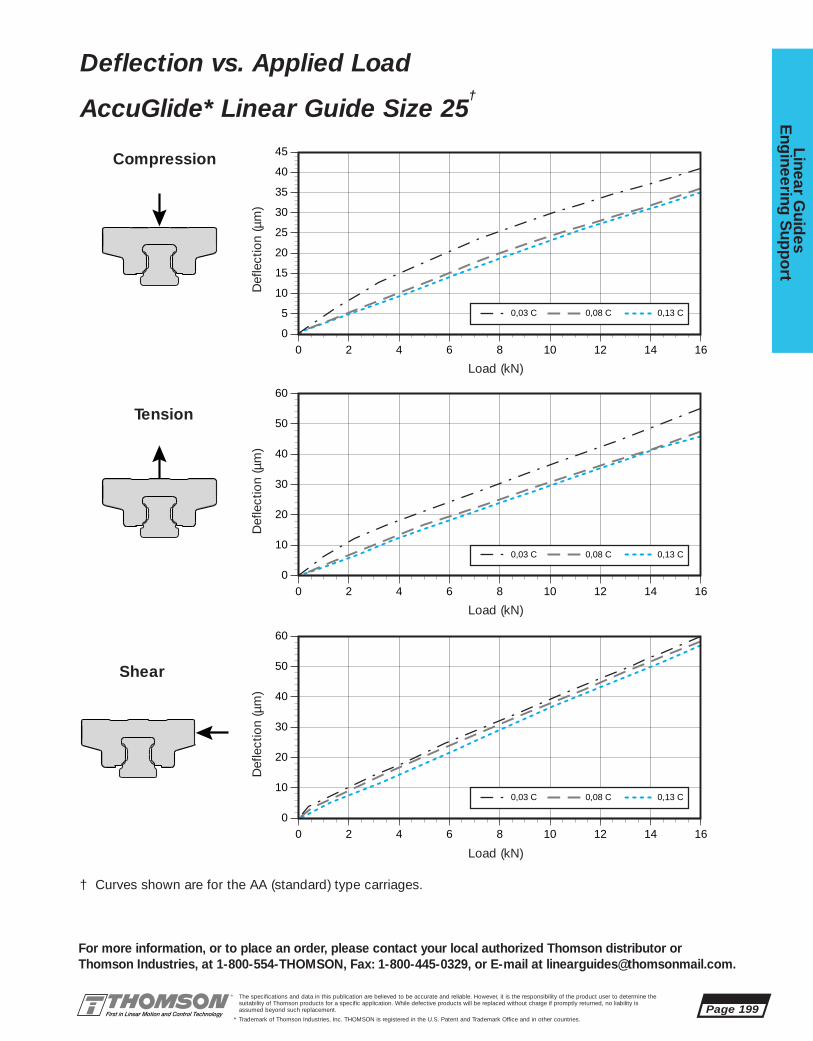
The specifications and data in this publication are believed to be accurate and reliable. However, it is the responsibility of the product user to determine thesuitability of Thomson products for a specific application. While defective products will be replaced without charge if promptly returned, no liability is assumed beyond such replacement.
* Trademark of Thomson Industries, Inc. THOMSON is registered in the U.S. Patent and Trademark Office and in other countries.
Linear Guid
esE
ngineering
Sup
po
rt
Page 199
For more information, or to place an order, please contact your local authorized Thomson distributor orThomson Industries, at 1-800-554-THOMSON, Fax: 1-800-445-0329, or E-mail at [email protected].
Compression
Tension
Shear
0
5
10
15
20
25
30
35
40
45
0 2 4 6 8 10 12 14 16
0,13 C0,08 C0,03 C
0
10
20
30
40
50
60
0 2 4 6 8 10 12 14 16
0,13 C0,08 C0,03 C
0
10
20
30
40
50
60
0 2 4 6 8 10 12 14 16
0,13 C0,08 C0,03 C
Load (kN)
Def
lect
ion
(µm
)
Load (kN)
Def
lect
ion
(µm
)
Load (kN)
Def
lect
ion
(µm
)
Deflection vs. Applied Load
AccuGlide* Linear Guide Size 25†
† Curves shown are for the AA (standard) type carriages.

Page 200The specifications and data in this publication are believed to be accurate and reliable. However, it is the responsibility of the product user to determine thesuitability of Thomson products for a specific application. While defective products will be replaced without charge if promptly returned, no liability is assumed beyond such replacement.
* Trademark of Thomson Industries, Inc. THOMSON is registered in the U.S. Patent and Trademark Office and in other countries.
Line
ar G
uid
esE
ngin
eeri
ng S
upp
ort
For more information, or to place an order, please contact your local authorized Thomson distributor orThomson Industries, at 1-800-554-THOMSON, Fax: 1-800-445-0329, or E-mail at [email protected].
Deflection vs. Applied Load
AccuGlide* Linear Guide Size 30†
Compression
Tension
Shear
0
5
10
15
20
25
30
35
40
45
50
0 5 10 15 20 25
0,13 C0,08 C0,03 C
0
10
20
30
40
50
60
0 5 10 15 20 25
0,13 C0,08 C0,03 C
0
10
20
30
40
50
60
0 5 10 15 20 25
0,13 C0,08 C0,03 C
Load (kN)
Def
lect
ion
(µm
)
Load (kN)
Def
lect
ion
(µm
)
Load (kN)
Def
lect
ion
(µm
)
† Curves shown are for the AA (standard) type carriages.

The specifications and data in this publication are believed to be accurate and reliable. However, it is the responsibility of the product user to determine thesuitability of Thomson products for a specific application. While defective products will be replaced without charge if promptly returned, no liability is assumed beyond such replacement.
* Trademark of Thomson Industries, Inc. THOMSON is registered in the U.S. Patent and Trademark Office and in other countries.
Linear Guid
esE
ngineering
Sup
po
rt
Page 201
For more information, or to place an order, please contact your local authorized Thomson distributor orThomson Industries, at 1-800-554-THOMSON, Fax: 1-800-445-0329, or E-mail at [email protected].
Compression
Tension
Shear
0
10
20
30
40
50
60
0 5 10 15 20 25 30
0,13 C0,08 C0,03 C
0
10
20
30
40
50
60
70
80
0 5 10 15 20 25 30
0,13 C0,08 C0,03 C
0
10
20
30
40
50
60
70
80
0 5 10 15 20 25 30
0,13 C0,08 C0,03 C
Load (kN)
Def
lect
ion
(µm
)
Load (kN)
Def
lect
ion
(µm
)
Load (kN)
Def
lect
ion
(µm
)
Deflection vs. Applied Load
AccuGlide* Linear Guide Size 35†
† Curves shown are for the AA (standard) type carriages.
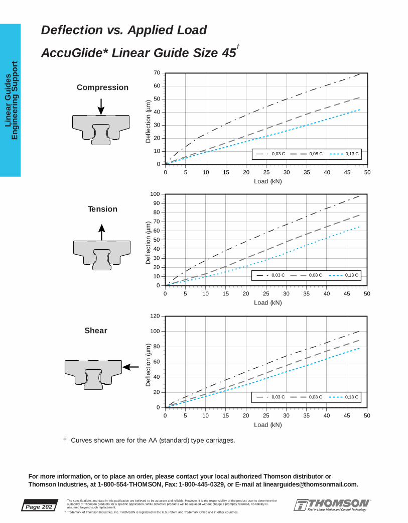
Page 202The specifications and data in this publication are believed to be accurate and reliable. However, it is the responsibility of the product user to determine thesuitability of Thomson products for a specific application. While defective products will be replaced without charge if promptly returned, no liability is assumed beyond such replacement.
* Trademark of Thomson Industries, Inc. THOMSON is registered in the U.S. Patent and Trademark Office and in other countries.
Line
ar G
uid
esE
ngin
eeri
ng S
upp
ort
For more information, or to place an order, please contact your local authorized Thomson distributor orThomson Industries, at 1-800-554-THOMSON, Fax: 1-800-445-0329, or E-mail at [email protected].
Deflection vs. Applied Load
AccuGlide* Linear Guide Size 45†
0
10
20
30
40
50
60
70
0 5 10 15 20 25 30 35 40 45 50
0,13 C0,08 C0,03 C
0
10
20
30
40
50
60
70
80
90
100
0 5 10 15 20 25 30 35 40 45 50
0,13 C0,08 C0,03 C
0
20
40
60
80
100
120
0 5 10 15 20 25 30 35 40 45 50
0,13 C0,08 C0,03 C
Compression
Tension
Shear
Load (kN)
Def
lect
ion
(µm
)
Load (kN)
Def
lect
ion
(µm
)
Load (kN)
Def
lect
ion
(µm
)
† Curves shown are for the AA (standard) type carriages.

The specifications and data in this publication are believed to be accurate and reliable. However, it is the responsibility of the product user to determine thesuitability of Thomson products for a specific application. While defective products will be replaced without charge if promptly returned, no liability is assumed beyond such replacement.
* Trademark of Thomson Industries, Inc. THOMSON is registered in the U.S. Patent and Trademark Office and in other countries.
Linear Guid
esE
ngineering
Sup
po
rt
Page 203
For more information, or to place an order, please contact your local authorized Thomson distributor orThomson Industries, at 1-800-554-THOMSON, Fax: 1-800-445-0329, or E-mail at [email protected].
0
10
20
30
40
50
60
70
80
0 10 20 30 40 50 60 70
0,13 C0,08 C0,03 C
0
20
40
60
80
100
120
0 10 20 30 40 50 60 70
0,13 C0,08 C0,03 C
0
20
40
60
80
100
120
140
0 10 20 30 40 50 60 70
0,13 C0,08 C0,03 C
Compression
Tension
Shear
Load (kN)
Def
lect
ion
(µm
)
Load (kN)
Def
lect
ion
(µm
)
Load (kN)
Def
lect
ion
(µm
)
Deflection vs. Applied Load
AccuGlide* Linear Guide Size 55†
† Curves shown are for the AA (standard) type carriages.
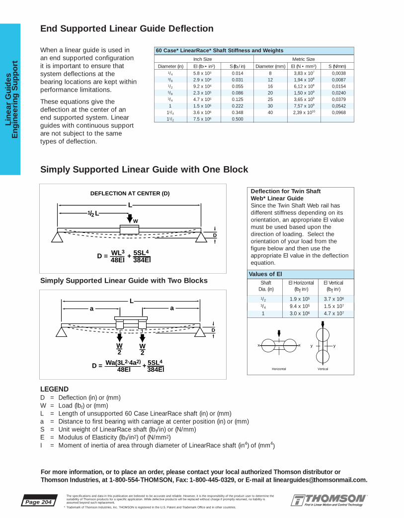
When a linear guide is used inan end supported configurationit is important to ensure thatsystem deflections at the bearing locations are kept withinperformance limitations.
These equations give thedeflection at the center of anend supported system. Linearguides with continuous supportare not subject to the sametypes of deflection.
1/4 5.8 x 10³ 0.014 8 3,83 x 10⁷ 0,00383/8 2.9 x 10⁴ 0.031 12 1,94 x 10⁸ 0,00871/2 9.2 x 10⁴ 0.055 16 6,12 x 10⁸ 0,01545/8 2.3 x 10⁵ 0.086 20 1,50 x 10⁹ 0,02403/4 4.7 x 10⁵ 0.125 25 3,65 x 10⁹ 0,03791 1.5 x 10⁶ 0.222 30 7,57 x 10⁹ 0,0542
11/4 3.6 x 10⁶ 0.348 40 2,39 x 10¹⁰ 0,096811/2 7.5 x 10⁶ 0.500
1/2 1.9 x 10⁵ 3.7 x 10⁶
3/4 9.4 x 10⁵ 1.5 x 10⁷
1 3.0 x 10⁶ 4.7 x 10⁷
Page 204The specifications and data in this publication are believed to be accurate and reliable. However, it is the responsibility of the product user to determine thesuitability of Thomson products for a specific application. While defective products will be replaced without charge if promptly returned, no liability is assumed beyond such replacement.
* Trademark of Thomson Industries, Inc. THOMSON is registered in the U.S. Patent and Trademark Office and in other countries.
Line
ar G
uid
esE
ngin
eeri
ng S
upp
ort
For more information, or to place an order, please contact your local authorized Thomson distributor orThomson Industries, at 1-800-554-THOMSON, Fax: 1-800-445-0329, or E-mail at [email protected].
End Supported Linear Guide Deflection
LEGENDD = Deflection (in) or (mm)W = Load (lbf) or (mm)L = Length of unsupported 60 Case LinearRace shaft (in) or (mm)a = Distance to first bearing with carriage at center position (in) or (mm)S = Unit weight of LinearRace shaft (lbf/in) or (N/mm)E = Modulus of Elasticity (lbf/in2) of (N/mm2)I = Moment of inertia of area through diameter of LinearRace shaft (in4) of (mm4)
Deflection for Twin Shaft Web* Linear GuideSince the Twin Shaft Web rail has different stiffness depending on itsorientation, an appropriate El valuemust be used based upon the direction of loading. Select the orientation of your load from the figure below and then use the appropriate El value in the deflectionequation.
60 Case* LinearRace* Shaft Stiffness and Weights
Inch Size Metric Size
Diameter (in) EI (lbf • in2) S (lbf / in) Diameter (mm) EI (N • mm2) S (N/mm)
Simply Supported Linear Guide with One Block
Simply Supported Linear Guide with Two BlocksValues of El
Shaft El Horizontal El VerticalDia. (in) (lbf in2) (lbf in2)
DEFLECTION AT CENTER (D)
L1/2 L
D
W
D = WL3 5SL4
48El 384El+
L
D
D = Wa(3L2-4a2) 5SL4
48El 384El+
W2
W2
a a
x x
Horizontal
y y
Vertical
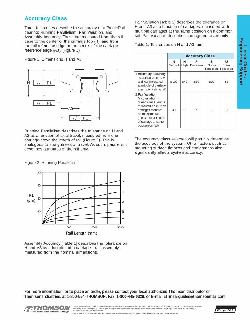
Accuracy Class
Three tolerances describe the accuracy of a ProfileRailbearing: Running Parallelism, Pair Variation, andAssembly Accuracy. These are measured from the railbase to the center of the carriage top (H), and from the rail reference edge to the center of the carriage reference edge (A3). (Figure 1)
Figure 1. Dimensions H and A3
Running Parallelism describes the tolerance on H andA3 as a function of axial travel, measured from one carriage down the length of rail (Figure 2). This is analogous to straightness of travel. As such, parallelismdescribes attributes of the rail only.
Figure 2. Running Parallelism
Assembly Accuracy [Table 1] describes the tolerance onH and A3 as a function of a carriage - rail assembly, measured from the nominal dimensions.
Pair Variation [Table 1] describes the tolerance on H and A3 as a function of carriages, measured with multiple carriages at the same position on a common rail. Pair variation describes carriage precision only.
Table 1. Tolerances on H and A3, µm
The accuracy class selected will partially determine the accuracy of the system. Other factors such as mounting surface flatness and straightness also significantly affects system accuracy.
Rail Length (mm)
P1(µm) P
H
N
S
U
1000
10
20
30
40
2000 3000
A3
H
P1
P1
P1
The specifications and data in this publication are believed to be accurate and reliable. However, it is the responsibility of the product user to determine thesuitability of Thomson products for a specific application. While defective products will be replaced without charge if promptly returned, no liability is assumed beyond such replacement.
* Trademark of Thomson Industries, Inc. THOMSON is registered in the U.S. Patent and Trademark Office and in other countries.
Linear Guid
esE
ngineering
Sup
po
rt
Page 205
For more information, or to place an order, please contact your local authorized Thomson distributor orThomson Industries, at 1-800-554-THOMSON, Fax: 1-800-445-0329, or E-mail at [email protected].
Accuracy ClassN H P S U
Normal High Precision Super UltraPrecision Precision
1. Assembly AccuracyTolerance on dim. Hand A3 (measured ±100 ±40 ±20 ±10 ±5at middle of carriageat any point along rail)
2.Pair VariationMax variation in dimensions H and A3 measured on multiple carriages mounted 30 15 7 5 3on the same rail (measured at middle of carriage at same position on rail)
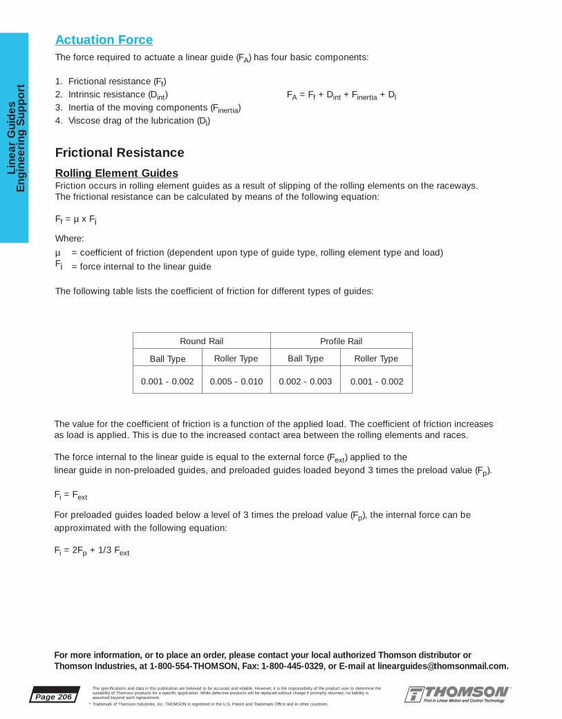
Page 206The specifications and data in this publication are believed to be accurate and reliable. However, it is the responsibility of the product user to determine thesuitability of Thomson products for a specific application. While defective products will be replaced without charge if promptly returned, no liability is assumed beyond such replacement.
* Trademark of Thomson Industries, Inc. THOMSON is registered in the U.S. Patent and Trademark Office and in other countries.
Line
ar G
uid
esE
ngin
eeri
ng S
upp
ort
For more information, or to place an order, please contact your local authorized Thomson distributor orThomson Industries, at 1-800-554-THOMSON, Fax: 1-800-445-0329, or E-mail at [email protected].
Actuation ForceThe force required to actuate a linear guide (FA) has four basic components:
1. Frictional resistance (Ff)2. Intrinsic resistance (Dint) FA = Ff + Dint + Finertia + Dl3. Inertia of the moving components (Finertia) 4. Viscose drag of the lubrication (Dl)
Frictional Resistance
Rolling Element GuidesFriction occurs in rolling element guides as a result of slipping of the rolling elements on the raceways. The frictional resistance can be calculated by means of the following equation:
Ff = µ x Fi
Where:
µ = coefficient of friction (dependent upon type of guide type, rolling element type and load)Fi = force internal to the linear guide
The following table lists the coefficient of friction for different types of guides:
Round Rail Profile Rail
Ball Type Roller Type
0.001 - 0.002 0.005 - 0.010
Ball Type Roller Type
0.002 - 0.003 0.001 - 0.002
The value for the coefficient of friction is a function of the applied load. The coefficient of friction increasesas load is applied. This is due to the increased contact area between the rolling elements and races.
The force internal to the linear guide is equal to the external force (Fext) applied to the linear guide in non-preloaded guides, and preloaded guides loaded beyond 3 times the preload value (Fp).
Fi = Fext
For preloaded guides loaded below a level of 3 times the preload value (Fp), the internal force can beapproximated with the following equation:
Fi = 2Fp + 1/3 Fext
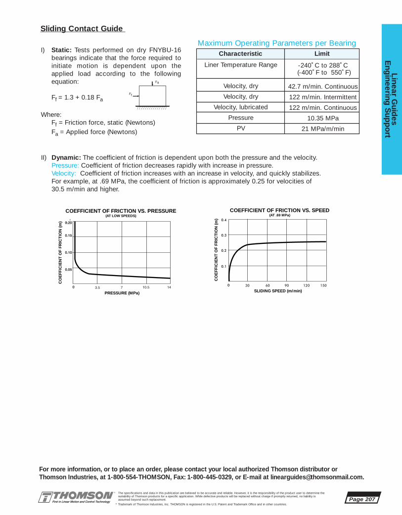
The specifications and data in this publication are believed to be accurate and reliable. However, it is the responsibility of the product user to determine thesuitability of Thomson products for a specific application. While defective products will be replaced without charge if promptly returned, no liability is assumed beyond such replacement.
* Trademark of Thomson Industries, Inc. THOMSON is registered in the U.S. Patent and Trademark Office and in other countries.
Linear Guid
esE
ngineering
Sup
po
rt
Page 207
For more information, or to place an order, please contact your local authorized Thomson distributor orThomson Industries, at 1-800-554-THOMSON, Fax: 1-800-445-0329, or E-mail at [email protected].
II) Dynamic: The coefficient of friction is dependent upon both the pressure and the velocity.Pressure: Coefficient of friction decreases rapidly with increase in pressure.Velocity: Coefficient of friction increases with an increase in velocity, and quickly stabilizes. For example, at .69 MPa, the coefficient of friction is approximately 0.25 for velocities of30.5 m/min and higher.
COEFFICIENT OF FRICTION VS. PRESSURE(AT LOW SPEEDS)
PRESSURE (MPa)
CO
EFF
ICIE
NT
OF
FRIC
TIO
N (m
)
COEFFICIENT OF FRICTION VS. SPEED(AT .69 MPa)
SLIDING SPEED (m/min)
CO
EFF
ICIE
NT
OF
FRIC
TIO
N (m
)
Sliding Contact Guide
I) Static: Tests performed on dry FNYBU-16bearings indicate that the force required toinitiate motion is dependent upon theapplied load according to the followingequation:
Ff = 1.3 + 0.18 Fa
Where:Ff = Friction force, static (Newtons)Fa = Applied force (Newtons)
Characteristic Limit
Liner Temperature Range
Velocity, dry
Velocity, dry
Velocity, lubricated
Pressure
PV
-240˚ C to 288˚ C (-400˚ F to 550˚ F)
42.7 m/min. Continuous
122 m/min. Intermittent
122 m/min. Continuous
10.35 MPa
21 MPa/m/min
Maximum Operating Parameters per Bearing
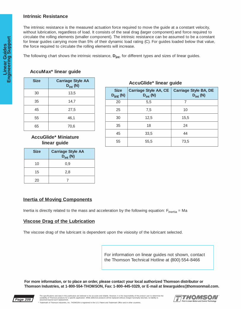
Intrinsic Resistance
The intrinsic resistance is the measured actuation force required to move the guide at a constant velocity,without lubrication, regardless of load. It consists of the seal drag (larger component) and force required tocirculate the rolling elements (smaller component). The intrinsic resistance can be assumed to be a constantfor linear guides carrying more than 5% of their dynamic load rating (C). For guides loaded below that value,the force required to circulate the rolling elements will increase.
The following chart shows the intrinsic resistance, Dint, for different types and sizes of linear guides.
Inertia of Moving Components
Inertia is directly related to the mass and acceleration by the following equation: Finertia = Ma
Viscose Drag of the Lubrication
The viscose drag of the lubricant is dependent upon the visiosity of the lubricant selected.
Size Carriage Style AA, CE Carriage Style BA, DEDint (N) Dint (N) Dint (N)
20 5,5 7
25 7,5 10
30 12,5 15,5
35 18 24
45 33,5 44
55 55,5 73,5
Size Carriage Style AADint (N)
10 0,9
15 2,8
20 7
Size Carriage Style AADint (N)
30 13,5
35 14,7
45 27,5
55 46,1
65 70,6
Page 208The specifications and data in this publication are believed to be accurate and reliable. However, it is the responsibility of the product user to determine thesuitability of Thomson products for a specific application. While defective products will be replaced without charge if promptly returned, no liability is assumed beyond such replacement.
* Trademark of Thomson Industries, Inc. THOMSON is registered in the U.S. Patent and Trademark Office and in other countries.
Line
ar G
uid
esE
ngin
eeri
ng S
upp
ort
For more information, or to place an order, please contact your local authorized Thomson distributor orThomson Industries, at 1-800-554-THOMSON, Fax: 1-800-445-0329, or E-mail at [email protected].
AccuMax* linear guide
AccuGlide* linear guide
AccuGlide* Miniature linear guide
For information on linear guides not shown, contact the Thomson Technical Hotline at (800) 554-8466
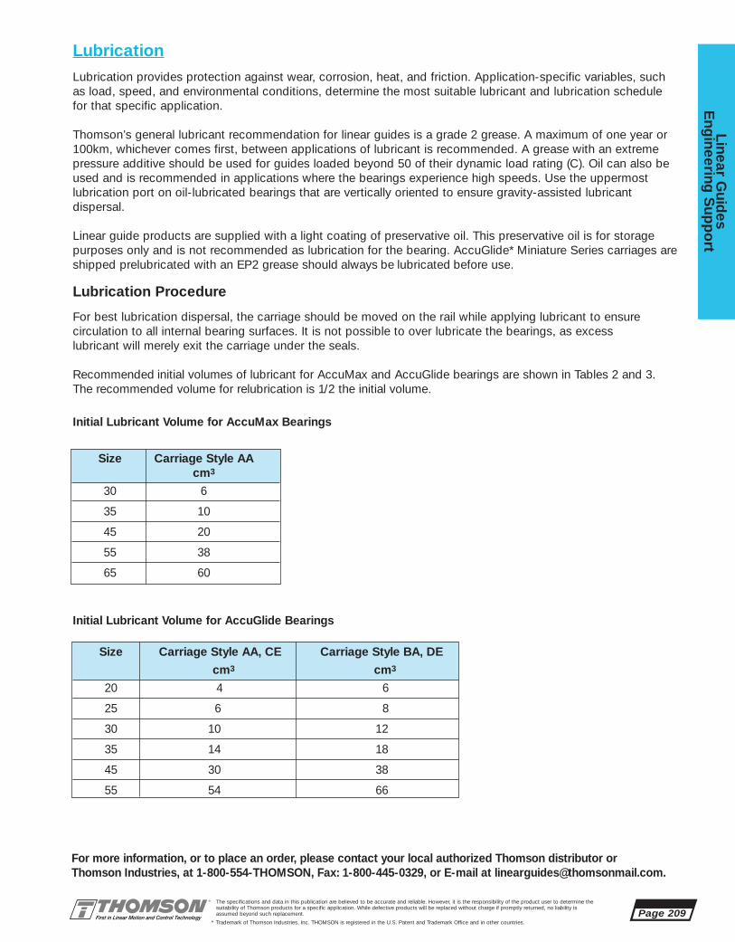
Size Carriage Style AA, CE Carriage Style BA, DE
cm3 cm3
20 4 6
25 6 8
30 10 12
35 14 18
45 30 38
55 54 66
LubricationLubrication provides protection against wear, corrosion, heat, and friction. Application-specific variables, suchas load, speed, and environmental conditions, determine the most suitable lubricant and lubrication schedulefor that specific application.
Thomson’s general lubricant recommendation for linear guides is a grade 2 grease. A maximum of one year or100km, whichever comes first, between applications of lubricant is recommended. A grease with an extremepressure additive should be used for guides loaded beyond 50 of their dynamic load rating (C). Oil can also beused and is recommended in applications where the bearings experience high speeds. Use the uppermostlubrication port on oil-lubricated bearings that are vertically oriented to ensure gravity-assisted lubricant dispersal.
Linear guide products are supplied with a light coating of preservative oil. This preservative oil is for storagepurposes only and is not recommended as lubrication for the bearing. AccuGlide* Miniature Series carriages areshipped prelubricated with an EP2 grease should always be lubricated before use.
Lubrication Procedure
For best lubrication dispersal, the carriage should be moved on the rail while applying lubricant to ensurecirculation to all internal bearing surfaces. It is not possible to over lubricate the bearings, as excess lubricant will merely exit the carriage under the seals.
Recommended initial volumes of lubricant for AccuMax and AccuGlide bearings are shown in Tables 2 and 3.The recommended volume for relubrication is 1/2 the initial volume.
Initial Lubricant Volume for AccuMax Bearings
Initial Lubricant Volume for AccuGlide Bearings
Size Carriage Style AAcm3
30 6
35 10
45 20
55 38
65 60
The specifications and data in this publication are believed to be accurate and reliable. However, it is the responsibility of the product user to determine thesuitability of Thomson products for a specific application. While defective products will be replaced without charge if promptly returned, no liability is assumed beyond such replacement.
* Trademark of Thomson Industries, Inc. THOMSON is registered in the U.S. Patent and Trademark Office and in other countries.
Linear Guid
esE
ngineering
Sup
po
rt
Page 209
For more information, or to place an order, please contact your local authorized Thomson distributor orThomson Industries, at 1-800-554-THOMSON, Fax: 1-800-445-0329, or E-mail at [email protected].
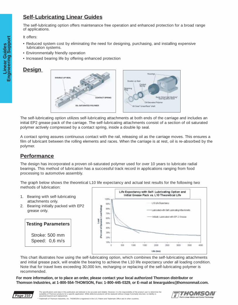
The self-lubricating option utilizes self-lubricating attachments at both ends of the carriage and includes aninitial EP2 grease pack of the carriage. The self-lubricating attachments consist of a section of oil saturatedpolymer actively compressed by a contact spring, inside a double lip seal.
A contact spring assures continuous contact with the rail, releasing oil as the carriage moves. This ensures afilm of lubricant between the rolling elements and races. When the carriage is at rest, oil is re-absorbed by thepolymer.
PerformanceThe design has incorporated a proven oil-saturated polymer used for over 10 years to lubricate radial bearings. This method of lubrication has a successful track record in applications ranging from food processing to automotive assembly.
The graph below shows the theoretical L10 life expectancy and actual test results for the following two methods of lubrication:
1. Bearing with self-lubricatingattachments only.
2. Bearing initially packed with EP2grease only.
This chart illustrates how using the self-lubricating option, which combines the self-lubricating attachmentsand initial grease pack, will enable the bearing to achieve the L10 life expectancy under all loading condition.Note that for travel lives exceeding 30,000 km, recharging or replacing of the self-lubricating polymer isrecommended.
Page 210The specifications and data in this publication are believed to be accurate and reliable. However, it is the responsibility of the product user to determine thesuitability of Thomson products for a specific application. While defective products will be replaced without charge if promptly returned, no liability is assumed beyond such replacement.
* Trademark of Thomson Industries, Inc. THOMSON is registered in the U.S. Patent and Trademark Office and in other countries.
Line
ar G
uid
esE
ngin
eeri
ng S
upp
ort
For more information, or to place an order, please contact your local authorized Thomson distributor orThomson Industries, at 1-800-554-THOMSON, Fax: 1-800-445-0329, or E-mail at [email protected].
Self-Lubricating Linear GuidesThe self-lubricating option offers maintenance free operation and enhanced protection for a broad range of applications.
It offers:
• Reduced system cost by eliminating the need for designing, purchasing, and installing expensivelubrication systems.
• Environmentally friendly operation• Increased bearing life by offering enhanced protection
Design
Testing Parameters
Stroke: 500 mmSpeed: 0,6 m/s

The specifications and data in this publication are believed to be accurate and reliable. However, it is the responsibility of the product user to determine thesuitability of Thomson products for a specific application. While defective products will be replaced without charge if promptly returned, no liability is assumed beyond such replacement.
* Trademark of Thomson Industries, Inc. THOMSON is registered in the U.S. Patent and Trademark Office and in other countries.
Linear Guid
esE
ngineering
Sup
po
rt
Page 211
For more information, or to place an order, please contact your local authorized Thomson distributor orThomson Industries, at 1-800-554-THOMSON, Fax: 1-800-445-0329, or E-mail at [email protected].
Calculations for Way Cover Extended Length & Rail Length
Given the Stroke and Distance Between Carriage Extremes:
Way Cover Extended Length (mm) = Stroke (mm) / (1-CR). After dividing, round number up to the nextincrement of 5mm. This value is used as the length in the way cover part number when ordering.
Note: The Way Cover Extended Length will be cut to next vee at the factory.
Way Cover Compressed Length (mm) = Way Cover Extended Length (mm) - Stroke (mm)
Rail Length = Compressed Length + Extended Length + Distance Between Carriage Extremes.
Example:Product: AccuGlide* Linear Guide Size 35Stroke Length = 200mmDistance Between Carriage Extremes = 520mmBellows Type = Walk-On
CR = 0.19 for size 35 AccuGlide Walk-on type bellows
Way Cover Extended Length = Stroke / (1-CR) = 200mm / (1-0.19) = 200mm / .81 = 246.91mmRound up to next increment of 5mm, therefore, Way Cover Extended Length = 250 mm
Way Cover Compressed Length = Way Cover Extended Length - Stroke = 250mm - 200mm = 50mm
Rail Length = Compressed Length + Extended Length + Distance Between Carriage Extremes = 50mm + 250mm + 520mm = 820mm
Calculations for Way Cover Extended Length & Rail Length

Page 212The specifications and data in this publication are believed to be accurate and reliable. However, it is the responsibility of the product user to determine thesuitability of Thomson products for a specific application. While defective products will be replaced without charge if promptly returned, no liability is assumed beyond such replacement.
* Trademark of Thomson Industries, Inc. THOMSON is registered in the U.S. Patent and Trademark Office and in other countries.
Line
ar G
uid
esE
ngin
eeri
ng S
upp
ort
For more information, or to place an order, please contact your local authorized Thomson distributor orThomson Industries, at 1-800-554-THOMSON, Fax: 1-800-445-0329, or E-mail at [email protected].
Specification sheet for the butting of 2 rails†
A butt joint will be require for rail lengths longer than the maximum shown in the chart below. If a buttjoint is required, the 1st and 2nd rail lengths must each be less than the maximum shown. The “Y1”and “Y2” dimensions must be between the minimum and maximum shown below to avoid cutting intoa mounting hole. The standard “Z” dimension should be used for best performance.
AccuMini* 10
AccuMini 15
AccuMini 20
AccuGlide* 15
AccuGlide 20
AccuGlide 25
AccuGlide 30
AccuGlide 35
AccuGlide 45
AccuGlide 55
AccuMax* 35
AccuMax 45
AccuMax 55
AccuMax 65*†
25
40
60
60
60
60
80
80
105
120
40
52.5
60
75
† Contact Factory for Availability
Linear GuideProduct
“X” dim
12.5
20
30
30
30
30
40
40
52.5
60
40
52.5
60
75
Standard“Z” dim
5
7
8
8
8
8
10
10
13
15
10
13
15
17
Minimum“Y” dim
20
33
52
52
52
52
70
70
92
105
30
39.5
45
58
Maximum“Y” dim
M2.5
M4
M5
M4
M5
M5
M8
M8
M12
M14
M8
M12
M14
M16
Fastenersize
1,500
1,500
3,000
3,000
3,000
3,000
3,000
3,000
3,000
3,000
3,000
3,000
3,000
3,000
Maximum lengthwithout a joint
Specification sheet for the butting of 3 or more rails†

www.thomsonsystems.com
SYSTEMS, SLIDES, & STAGES SOLUTIONSSYSTEMS, SLIDES, & STAGES SOLUTIONS
SYSTEMS, SLIDES & STAGES• Pre-engineered, pre-assembled, ready to install
• The most complete product line available
THOMSON INDUSTRIES, INC.
Engineering Guide for Systems, Slides & Stages
For Application Engineering assistance contact the Thomson Technical HelpLine at 1-800-554-8466.* Trademark of Thomson Industries, Inc. THOMSON is registered in the U.S. Patent and Trademark Office and in other countries. Page 213
System
s, Slid
es, and S
tages

Page 214For Application Engineering assistance contact the Thomson Technical HelpLine at 1-800-554-8466.
* Trademark of Thomson Industries, Inc. THOMSON is registered in the U.S. Patent and Trademark Office and in other countries.
Sys
tem
s, S
lides
, and
Sta
ges
Thomson IBL Ball Screws for High Accuracy and Repeatability
Put Over 50 Years Of Linear Motion
Thomson Precision Balls–Load Carrying Element for the
Super Smart Ball Bushing Bearing
Super Smart Ball Bushing* bearing• 216 Times the Travel Life or• 6 Times the Load Capacity
• 5 Times the Shaft Life
Metric SuperSlide* 2RBBall Screw Drive System
(See page 262 for more details)
Thomson 60 Case* shaftingProvides Superior LinearRace*
Way Performance
Thomson Saginaw Ball ScrewsProvide High Efficiency and
Reliable Performance
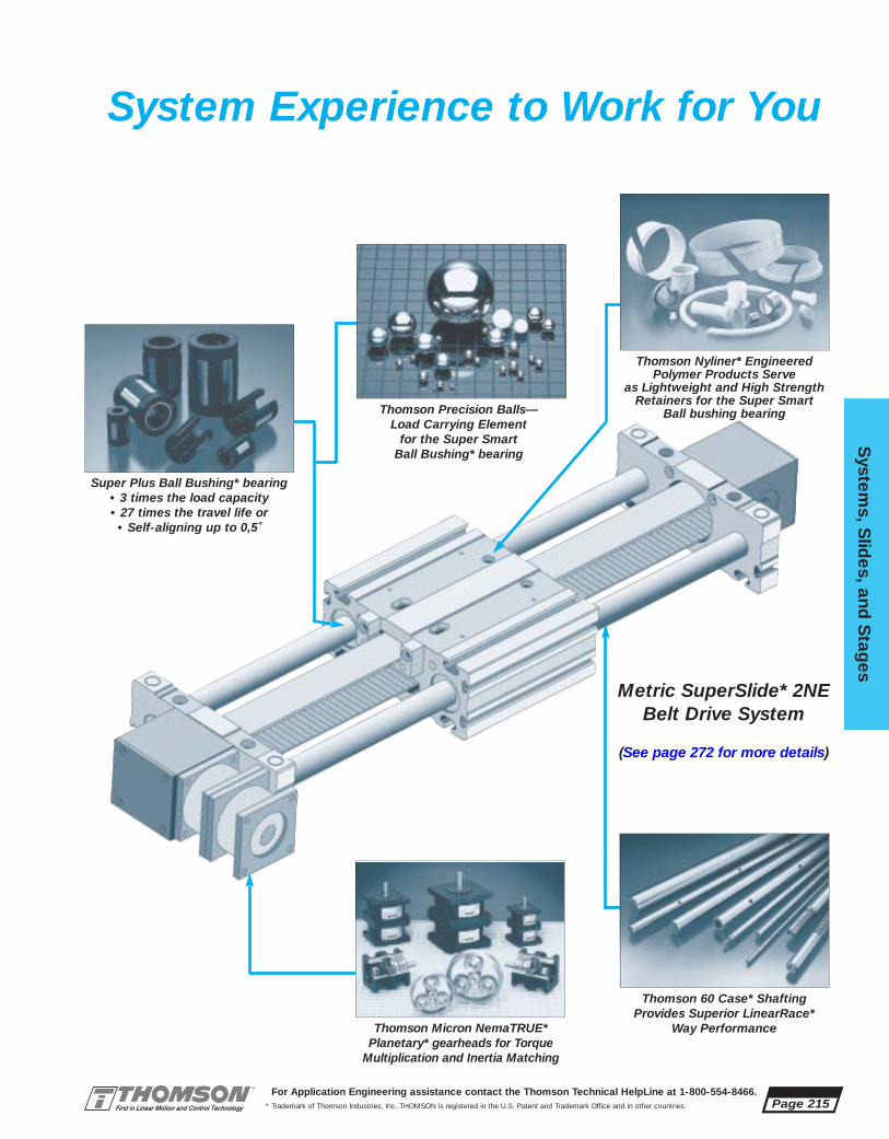
For Application Engineering assistance contact the Thomson Technical HelpLine at 1-800-554-8466.* Trademark of Thomson Industries, Inc. THOMSON is registered in the U.S. Patent and Trademark Office and in other countries.
System
s, Slid
es, and S
tages
Page 215
System Experience to Work for You
Thomson 60 Case* Shafting Provides Superior LinearRace*
Way Performance
Thomson Precision Balls—Load Carrying Element
for the Super Smart Ball Bushing* bearing
Thomson Micron NemaTRUE*Planetary* gearheads for Torque
Multiplication and Inertia Matching
Thomson Nyliner* EngineeredPolymer Products Serve
as Lightweight and High StrengthRetainers for the Super Smart
Ball bushing bearing
Super Plus Ball Bushing* bearing• 3 times the load capacity• 27 times the travel life or
• Self-aligning up to 0,5˚
Metric SuperSlide* 2NEBelt Drive System
(See page 272 for more details)
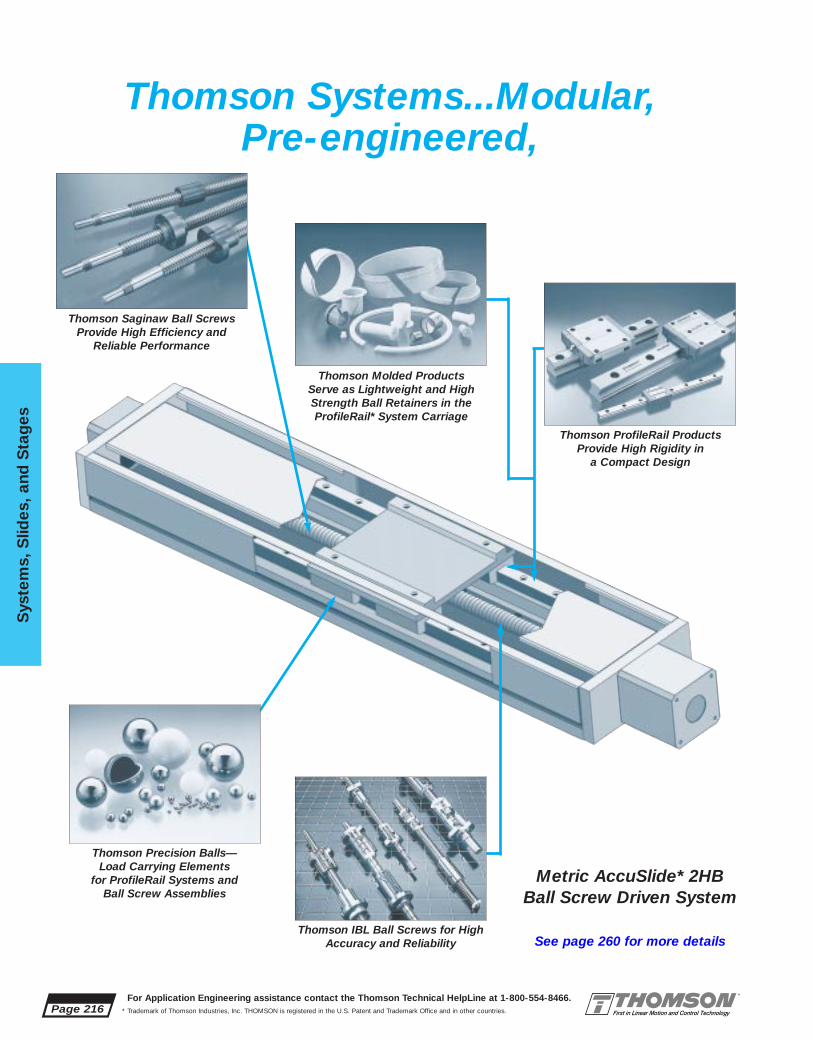
Page 216For Application Engineering assistance contact the Thomson Technical HelpLine at 1-800-554-8466.
* Trademark of Thomson Industries, Inc. THOMSON is registered in the U.S. Patent and Trademark Office and in other countries.
Sys
tem
s, S
lides
, and
Sta
ges
Thomson Precision Balls—Load Carrying Elements
for ProfileRail Systems and Ball Screw Assemblies
Thomson Systems...Modular,Pre-engineered,
Thomson IBL Ball Screws for HighAccuracy and Reliability
Thomson ProfileRail ProductsProvide High Rigidity in
a Compact Design
Thomson Molded Products Serve as Lightweight and HighStrength Ball Retainers in theProfileRail* System Carriage
Metric AccuSlide* 2HBBall Screw Driven System
See page 260 for more details
Thomson Saginaw Ball ScrewsProvide High Efficiency and
Reliable Performance

For Application Engineering assistance contact the Thomson Technical HelpLine at 1-800-554-8466.* Trademark of Thomson Industries, Inc. THOMSON is registered in the U.S. Patent and Trademark Office and in other countries.
System
s, Slid
es, and S
tages
Page 217
Thomson Precision Balls—Load Carrying Elements forProfileRail* Linear Bearing
Systems
AccuMax* Linear Roller Bearing System
• Twice the load capacity of linearball guide systems
• Twice the rigidity of linear ballguide systems
• Offers the Arcuate Advantage* a patented design which
includes cylindrical rollers on continuously crowned races
Turbo Module* 2GEBelt Driven System
Thomson Nyliner* EngineeredPolymer Products Serve as
Lightweight and High StrengthBall Retainers in the ProfileRail
System Carriage
Pre-assembled, Ready to Ship,Ready to Install
Thomson Micron AccuTRUE*Planetary Gearheads for Torque
Multiplication and Inertia Matching
See page 279 for more details.

Page 218For Application Engineering assistance contact the Thomson Technical HelpLine at 1-800-554-8466.
* Trademark of Thomson Industries, Inc. THOMSON is registered in the U.S. Patent and Trademark Office and in other countries.
Sys
tem
s, S
lides
, and
Sta
ges
Thomson Systems . . .MicroStage*
Lead Screw Actuated Linear Motion System
Drive OptionsA wide range of leads are
available. A variety of motor control options are also available
from Thomson. Integral motoradaptor and coupling are
standard for easy connection ofindustry standard stepper and
servo motors.
Rugged, but lightweight construction is manufactured
from aluminum alloys to provide strength and rigidity. Thisunique design provides for lower
inertia and higher performance versus either
built-in, or external actuators.Smooth Precision Linear
Motion incorporates a unique bearing segment design and
offers a backlash-free slide assembly without
sacrificing load capacity orsmoothness.
Flexible MountingConfiguration MicroStage linear
guides offer hole patterns and T-slots for easy interchange and
simple X-Y mounting.
See page 245 for more details.

2BB
The specifications and data in this publication are believed to be accurate and reliable. However, it is the responsibility of the product user to determine thesuitability of Thomson products for a specific application. While defective products will be replaced without charge if promptly returned, no liability isassumed beyond such replacement.
* Trademark of Thomson Industries, Inc. THOMSON is registered in the U.S. Patent and Trademark Office and in other countries.
System
s, Slid
es, and S
tages - Inch
Page 219
Accessories
Ball ScrewAssemblies
Hand WheelsRadial Mount Shaft Extender Brake Options
Protective Bellows Couplings and Motor Mounting Blocks
Electric BrakeController
Preloaded and Non-Preloaded
SuperSlide*Ball Screw Actuated SystemsFor End Supported Applications
2AB 2CB
2DB 2EB
For Continuously Supported Applications
Page 224 Page 226 Page 228
Page 230 Page 234
Page 236
Page 292 Page 308 Page 304
Page 291 Page 288 Page 306

Page 220The specifications and data in this publication are believed to be accurate and reliable. However, it is the responsibility of the product user to determine thesuitability of Thomson products for a specific application. While defective products will be replaced without charge if promptly returned, no liability isassumed beyond such replacement.
* Trademark of Thomson Industries, Inc. THOMSON is registered in the U.S. Patent and Trademark Office and in other countries.
Sys
tem
s, S
lides
, and
Sta
ges
- I
nch
For more information, or to place an order, please contact Thomson Industries, at 1-800-554-THOMSON, Fax: 1-800-445-0329, or E-mail at [email protected].
AccessoriesMotor Couplings, and Motor Adaptor Blocks, Limit SwitchPackages, Protective Shroud Covers, Radial Mount, ProtectiveBellows and Brake OptionsThe uniquely designed Radial Mount Ball screw shaft extender consists of an oversized shaft, a heavy duty radial bearing, a housing with a standard NEMA mountingface and an easy to mount coupling. The Radial Mount provides a dramatic increase inside or cantilever load capacity. All Protective Bellows are manufactured from a durablepolyurethane coated polyester material which will protect your Linear Motion Systemfrom most contaminants or corrosive environments. The flexible convoluted folding construction reinforced with bonded integral stiffeners minimizes the reduction in systemstroke length. Compact design eliminates work surface interference and assures uninterrupted movement of the carriage during operation. Brake Options are available inthree versions. QuickSlide* 2DA Manual Brake System allows the system carriage tohave infinite fixed positioning capability. The Electric Brake is used with all SuperslideSystems and Ball Screw Assemblies. The Electric Brake is designed to engage whenpower is lost. The Electric Brake can be equipped with a controller option that interfacesdirectly with a PLC, switch, relay, computer, or controller output. Available from over 1800authorized distributor locations worldwide. (See page 287)
Ball Screw AssembliesBall Screw Assemblies are available in metric or inch sizes in over fifty diameters andlead combinations. Each Ball Screw Assembly consists of a ball screw, a ball screw nutwith mounting surfaces and two mounting blocks equipped with sealed angular contactbearings. The motor end block is designed for mounting to NEMA 23, 34 and 42 standards. Inch size Ball Screw assemblies are available in sizes .500 x .200 through1.500 x 1.875 in both preloaded and non-preloaded versions. Metric Ball ScrewAssemblies are available in sizes 12 mm x 5 mm through 40 mm x 40 mm in both preloaded and non-preloaded versions. They are designed to easily mount to the carriage of Building Block System 1CC and can be modified to mount to any manual-ly driven system. Standard Ball Screw Assembly positioning accuracy is better than.002 inch per foot (.025 mm per 300 mm) and standard repeatability is less than .002inch (0.05 mm). Most Ball Screw Assembly Systems are available with preloaded ballscrew assemblies achieving repeatabilities as low as .0002 inch (.005 mm). StandardBall Screw Assemblies are shipped in less than a week with special length Assembliesshipped in less than two weeks. (See page 236)
SuperSlide Ball Screw Actuated Systemsfor End and Continuously Supported ApplicationsSuperSlide* Ball Screw Driven Systems are available in five configurations with overfifty different drive diameters and leads designed to meet the most stringent of applications. End supported systems are designed to be used when spanning orbridging a gap. Continuously supported systems are used when rigidity is required.Standard system positioning accuracy is less than .002 inch per foot and standardrepeatability is less than .002 inch. Most SuperSlide systems are available with preloaded ball screw assemblies achieving repeatabilities as low as .0002 inch. AllSuperSlide systems are available with polyurethane coated polyester bellows for corrosion resistant applications. Superslide systems are shipped in less than a weekwith special length systems shipped in less than two weeks. Available from over1800 authorized distributor locations worldwide. (See page 221)

The specifications and data in this publication are believed to be accurate and reliable. However, it is the responsibility of the product user to determine thesuitability of Thomson products for a specific application. While defective products will be replaced without charge if promptly returned, no liability isassumed beyond such replacement.
* Trademark of Thomson Industries, Inc. THOMSON is registered in the U.S. Patent and Trademark Office and in other countries.
System
s, Slid
es, and S
tages - Inch
Page 221
For more information, or to place an order, please contact Thomson Industries, at 1-800-554-THOMSON, Fax: 1-800-445-0329, or E-mail at [email protected].
Thomson SuperSlide* Systems offer:• A pre-engineered, pre-assembled linear motion
system complete with prealigned LinearRace*ways and an integral ball screw assembly. A single part number specifies a complete system.
• A variety of highly efficient ball screw assemblies with diameters and leads designedto meet the most stringent motion controlrequirements.
• Available with the Super Smart Ball Bushing*bearings which provide up to twice the loadcapacity or eight times the travel life of standard Super Ball Bushing* bearing basedsystems.
• Positioning accuracy as low as .001 inch perfoot with repeatability better than .0002 inch.
• An end supported or continuously supportedversion. End Supported Systems are usedwhen spanning or bridging a gap.
Continuously Supported Systems are usedwhen rigidity is required.
• Easy integration to the TMC 1000 MotionControl options using the standard NEMAface mounted hole spacing. Motion control of exacting standards is realized immediately.
• Available with standard carriages that providesmooth and virtually frictionless linear movement.
• Four drilled and tapped holes for quick andeasy mounting of the work piece to the carriage.
• Optional protective bellows, a black anodizedcoating, lubrication fittings and integral doubleacting seals for protection in corrosive environments.
• Travel speeds up to 10 ft/s with high positioning accuracy and repeatability.
• Available from over 1800 distributors worldwide.
SuperSlideBall Screw Actuated Systems
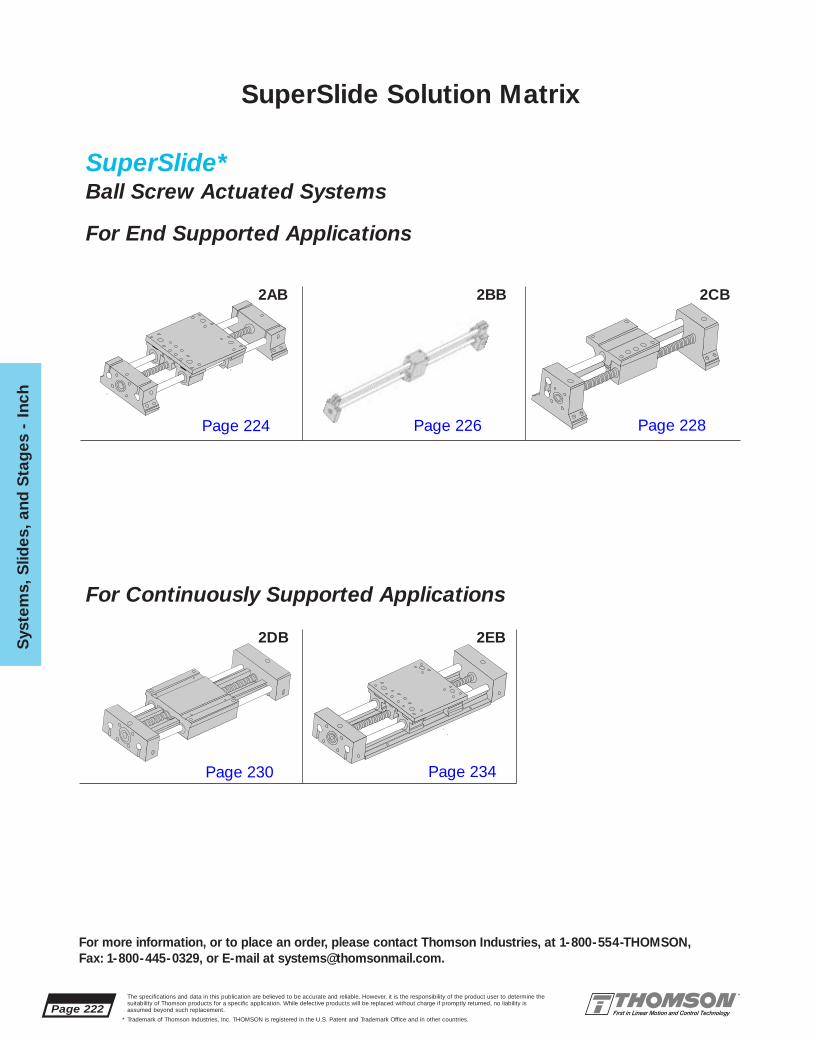
Page 222The specifications and data in this publication are believed to be accurate and reliable. However, it is the responsibility of the product user to determine thesuitability of Thomson products for a specific application. While defective products will be replaced without charge if promptly returned, no liability isassumed beyond such replacement.
* Trademark of Thomson Industries, Inc. THOMSON is registered in the U.S. Patent and Trademark Office and in other countries.
Sys
tem
s, S
lides
, and
Sta
ges
- I
nch
For more information, or to place an order, please contact Thomson Industries, at 1-800-554-THOMSON, Fax: 1-800-445-0329, or E-mail at [email protected].
SuperSlide*Ball Screw Actuated Systems
For End Supported Applications
For Continuously Supported Applications
SuperSlide Solution Matrix
2AB 2BB 2CB
2DB 2EB
Page 224 Page 226 Page 228
Page 230 Page 234

The specifications and data in this publication are believed to be accurate and reliable. However, it is the responsibility of the product user to determine thesuitability of Thomson products for a specific application. While defective products will be replaced without charge if promptly returned, no liability isassumed beyond such replacement.
* Trademark of Thomson Industries, Inc. THOMSON is registered in the U.S. Patent and Trademark Office and in other countries.
System
s, Slid
es, and S
tages - Inch
Page 223
For more information, or to place an order, please contact Thomson Industries, at 1-800-554-THOMSON, Fax: 1-800-445-0329, or E-mail at [email protected].
Many variables influence the selection of a Linear Motion System. The best solutiondemands a thorough evaluation of the application; only then can design criteria beestablished. Issues such as envelope limitations, system load capacity, actuator loadcapacity, speed and acceleration, drive requirements, accuracy and repeatability, andoperating environment are looked at from a broad perspective to determine the type ofsystem, type of actuator, and whether the system need be built of special materials.
Typically, a ball screw actuated linear motion system is ideal for tight precision, highlyrepeatable, high load, moderate speed applications. Long lead ball screws are availablefor most style systems, but it is important to be mindful of the critical speed (first harmonic of the resonant ball screw whirling vibration) in longer stroke systems whenattempting to reach higher linear velocities. If an application requires rigidity, then a fullysupported system should be specified in lieu of an end supported type system. Whenzero backlash is required for the best repeatability, then a preloaded version ball screwassembly need be specified. For extremely heavy-duty applications, the AccuSlide (2HBseries) system, with its use of ProfileRail type linear guides is adept at handling normalaxis, overhung, or cantilever loads of increased magnitude. In environments that are corrosive or high temperature, special materials may be required and are available.Contact Application Engineering for details on special materials.
In order to determine the Ball Screw Actuated SuperSlide System that meets the needsof your application, it is first necessary to evaluate the following detail design criteria:
• System support requirements• System stroke length• Maximum allowable shaft deflection• Required travel life• Force on the most heavily loaded bearing• Load correction factor• Load/Life requirements - linear bearings• Load/Life requirements - ball screws• Motion (move) profile (velocity, acceleration)• Maximum acceptable travel rate• Torque considerations• Size motor using torque/speed curves
A detailed explanation of the procedure for selecting a Ball Screw Actuated LinearMotion System is given on page 310 in the Engineering Support Section.
SuperSlide* Ball Screw Actuated SystemsSelection Criteria

Page 224The specifications and data in this publication are believed to be accurate and reliable. However, it is the responsibility of the product user to determine thesuitability of Thomson products for a specific application. While defective products will be replaced without charge if promptly returned, no liability isassumed beyond such replacement.
* Trademark of Thomson Industries, Inc. THOMSON is registered in the U.S. Patent and Trademark Office and in other countries.
Sys
tem
s, S
lides
, and
Sta
ges
- I
nch
For more information, or to place an order, please contact Thomson Industries, at 1-800-554-THOMSON, Fax: 1-800-445-0329, or E-mail at [email protected].
Superslide* 2ABDouble End Supported Systemwith Carriage and Integral Ball Screw Assembly
New... Super SmartBall Bushing* Bearing...Now Available in Select Sizes
B6
G
L
T1
L1L3
H3H1
B2
B
H7
H
B4 T
B3
FN1N
M
M1
L5 L6 Maximum Stroke Length
is determined by subtracting thecarriage length (T1) and 2x the end support length (L3) from the total system length.
Superslide 2AB with Carriage and Integral Ball Screw Assembly (Dimensions in inches)
2AB-08-ARB-B .50 12mm x 5mm NP <.002 <.002 1.69 1.5 .75 .38 5.5 2.187 1.13 2.37 .38 .482AB-08-ARB-F .500 x .200 NP <.002 <.0022AB-08-ARB-V .500 x .200 P <.002 ±.00022AB-08-ARB-Q .500 x .500 P <.002 ±.00022AB-12-ARB-D .75 20mm x 5mm NP <.002 <.002 2.06 2.0 1.00 .50 7.5 2.937 1.50 2.70 .50 .602AB-12-ARB-G .750 x .200 NP <.002 <.0022AB-12-ARB-W .750 x .200 P <.002 ±.00022AB-12-ARB-L .631 x 1.00 P <.002 ±.00022AB-12-ARB-U 20mm x 20mm NP <.002 <.0022AB-16-ARB-H 1.00 x .250 P <.002 ±.00022AB-16-ARB-T 1.00 1.00 x 1.00 P <.002 ±.0002 2.81 2.2 1.20 .50 9.0 3.437 1.75 3.45 .50 .602AB-24-ARB-I 1.50 x .250 P <.002 ±.00022AB-24-ARB-J 1.50 1.50 x 1.00 P <.002 ±.0002 4.00 2.8 1.5 .65 13.0 5.000 2.50 5.00 .75 .812AB-24-ARB-Z 1.50 x 1.875 P <.002 ±.0002
Thomson actuated systems utilizestandard NEMA motor mountingconfigurations for each system size.
System Motor Size2AB-08 NEMA 232AB-12 NEMA 232AB-16 NEMA 342AB-24 NEMA 42
Part Nom. Ball Screw Accuracy Repeatability L1 L3 L5 L6 T1 H H1 H3 H6 H7Number Dia. Assembly in/ft in
Custom Lengths and Delivery Information
Systems ordered in standard lengths andlonger lengths in increments of (X) are typicallyshipped in three to four weeks. Custom lengthsystems are available and require four to sixweeks for delivery. For special requirements,please contact the Thomson Systems application engineering department.
SuperSlide System 2AB Standard Lengths (Lengths in inches)System 18 24 30 32 36 40 42 48 54 56 60 64 66 72 X MAX2AB-08 ■ ■ ■ ■ 6 722AB-12 ■ ■ ■ ■ ■ ■ 6 962AB-16 ■ ■ ■ ■ ■ ■ ■ ■ ■ ■ 6 1442AB-24 ■ ■ ■ ■ ■ ■ ■ 8 178
< Indicates Less ThanP- Indicates preloaded ball screw.NP- Indicates non-preloaded ball screw.For Motion Control Options refer to the Motion Control Section, page 381.To determine system Torque Requirements or Ball Screw travel life refer to theEngineering Support Appendix, see page 310.For Bellows Way Covers, see page 291.For Radial Mount Ball Screw Shaft Extenders, see page 292.For Spring Set Electric Brakes, see page 304.
For motor coupling and motor mounting blockspecifications see the accessories section, page 288.
End supported systems are subject to shaft deflection based on load. Each application must be checked for maximum allowable shaft deflection.

The specifications and data in this publication are believed to be accurate and reliable. However, it is the responsibility of the product user to determine thesuitability of Thomson products for a specific application. While defective products will be replaced without charge if promptly returned, no liability isassumed beyond such replacement.
* Trademark of Thomson Industries, Inc. THOMSON is registered in the U.S. Patent and Trademark Office and in other countries.
System
s, Slid
es, and S
tages - Inch
Page 225
For more information, or to place an order, please contact Thomson Industries, at 1-800-554-THOMSON, Fax: 1-800-445-0329, or E-mail at [email protected].
SuperSlide* 2AB Benefits:■ Used when spanning or bridging a gap.■ System is prealigned for quick and
easy installation.■ Integrated Ball Screw Assembly
with standard NEMA motor mounting.■ Single part number is all that is
required to specify.■ Designed for medium loads.
SuperSlide 2AB Components:■ 4 Super Smart* Ball Bushing* pillow
blocks■ 2 60 Case* LinearRace* ways■ 2 Integrated double end supports
with angular contact bearings■ 1 mounting carriage top
Specifying a Thomson System:1. Determine the proper system for your load and liferequirements. 2. Select the part number. 3. Add theletter “L” followed by the overall length in inches, as asuffix to the part number (choosing a standard lengthwill reduce costs and speed delivery). 4. Place your order with your local authorizedThomson distributor.Part Numbering System
2AB-12-ARB-D L24System System Designation LengthNominal Diameter Ball Screw
Type of Bearing Block Type of CarriageType of Support
SuperSlide 2AB with Carriage and Integral Ball Screw Assembly (Dimensions in inches)Part H9 B R T B2 B3 B4 B6 N N1 M M1 F G Max.
Number Bolt Hole StrokeLength
2AB-08-ARB-B 1.25 5.3 1.025 5.5 3.25 4.8 4.25 .25 4.5 .50 3.25 1.13 1/4-20 #8 .19 L-(8.5)2AB-08-ARB-F2AB-08-ARB-V2AB-08-ARB-Q2AB-12-ARB-D 1.75 7.2 1.350 7.5 4.50 6.7 6.0 .25 6.0 .75 4.5 1.50 5/16-18 #10 .22 L-(11.5)2AB-12-ARB-G2AB-12-ARB-W2AB-12-ARB-L2AB-12-ARB-U2AB-16-ARB-T 2.19 8.7 1.600 9.0 5.50 8.0 7.25 .35 7.0 1.00 5.5 1.75 3/8-16 1/4 .28 L-(13.4)2AB-16-ARB-H2AB-24-ARB-J 3.25 13.0 2.500 13.0 8.00 12.0 10.75 .50 10.0 1.50 8.0 2.50 1/2-13 5/16 .34 L-(18.6)2AB-24-ARB-I2AB-12-ARB-Z
Determining the SuperSlide Systemfor your application:To determine the System which best meets your needs, calculate travel life vs. load based on your application criteria. Calculate the load on the most heavily loaded bearing and total travel liferequirements from stroke length and duty cycle.Select the System with a rated load life aboveyour plotted point.
The SuperSlide has a pre-designed MaximumAcceptable Travel Rate. Calculate maximumrotational speed (rpm) by dividing your requiredmaximum linear speed (in/min) by the corresponding system ball screw lead (in/rev.). Enter the chartwith the required system length and your maximum rotational speed. Select the system with a maximumacceptable travel rate curve above the plotted line.
Compressive load on the ball screw is a keyfactor in selecting the proper System. Using maximum load and acceleration requirements, plot compressive load on the left side of the chart.Using System length and compressive load. plot the maximum allowable compressive force on the right chart. Select the System with a rated maximumcompressive force above your plotted point.
If you have questions concerning your systemrequirements, contact the Thomson Systemsapplication engineering department.
Note: Ball screw should never exceed recommended critical speed.
R
H9
H6 Load/Life GraphLines indicate limiting load for given shaft size
110
10
100
100
1,000
1,000
10,000
10,000
Required Travel Life (million of inches)
2AB-08
2AB-24
2AB-162AB-12
10 000
5 000
2 000
1 000
500
200
100
50
20
106 12 18 24 30 36 42 48 54 60 66 72
Maximum Recommended Load on System
System Length (in)
Load
on
Sys
tem
(lb
f) 2AB-24
2AB-16
2AB-12
2AB-08
Maximum AcceptableTravel Rate*
10010 20 30 40 60 100
System Length (in)*80% of Critical Speed
5000
1000
2000
200
500
Ro
tati
ona
l Sp
eed
(rp
m)
200 100 1000 10000 100000 18 24 30 36 42 48 54 60 66 7210
10000
1000
2000
30004000
6000
100
200
300400600
Co
mp
ress
ive
Load
on
Scr
ew (l
bf)
Load on Carriage (lbf)
Acceleration (ft/s2)10 6 4
10000
1000
2000
30004000
6000
100
200
400
600
Co
mp
ressive Load
on S
crew (lb
f)
System Length (in)
80 8012
100 60 40 30
20 x 20 NP
12 x 5 NP.5 x .2 P/NP.5 X .5 P
20 x 5 NP.75 x .2 P/NP
1 x 1 P1 x .25 P
1.5 x 1 P1.5 x 1.875 P
20 x 20 NP
20 x 5 NP12 x 5 NP
.5 x .2 P/NP
.75 x .2 P/NP.5 X .5 P
1.5 x 1 P
1.5 x 1.875 P
1 x 1 P1 x .25 P
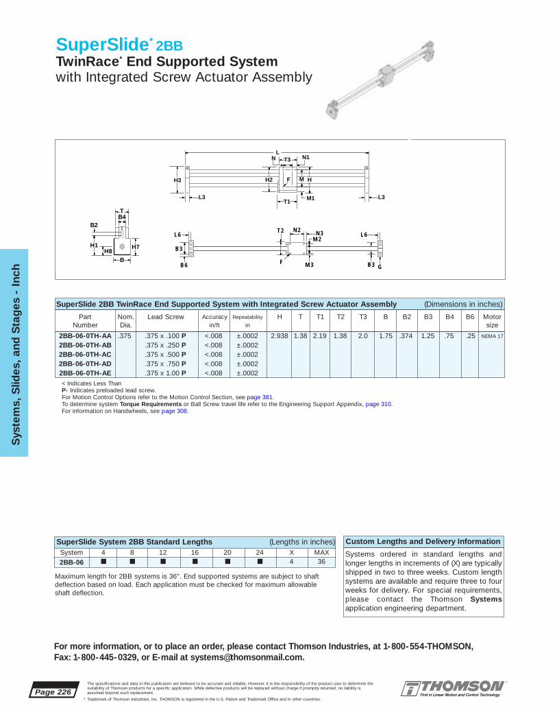
Page 226The specifications and data in this publication are believed to be accurate and reliable. However, it is the responsibility of the product user to determine thesuitability of Thomson products for a specific application. While defective products will be replaced without charge if promptly returned, no liability isassumed beyond such replacement.
* Trademark of Thomson Industries, Inc. THOMSON is registered in the U.S. Patent and Trademark Office and in other countries.
Sys
tem
s, S
lides
, and
Sta
ges
- I
nch
For more information, or to place an order, please contact Thomson Industries, at 1-800-554-THOMSON, Fax: 1-800-445-0329, or E-mail at [email protected].
SuperSlide* 2BBTwinRace* End Supported Systemwith Integrated Screw Actuator Assembly
System 4 8 12 16 20 24 X MAX2BB-06 ■ ■ ■ ■ ■ ■ 4 36
Custom Lengths and Delivery Information
Systems ordered in standard lengths andlonger lengths in increments of (X) are typicallyshipped in two to three weeks. Custom lengthsystems are available and require three to fourweeks for delivery. For special requirements,please contact the Thomson Systems application engineering department.
SuperSlide 2BB TwinRace End Supported System with Integrated Screw Actuator Assembly (Dimensions in inches)
2BB-06-0TH-AA .375 .375 x .100 P <.008 ±.0002 2.938 1.38 2.19 1.38 2.0 1.75 .374 1.25 .75 .25 NEMA 17
2BB-06-0TH-AB .375 x .250 P <.008 ±.00022BB-06-0TH-AC .375 x .500 P <.008 ±.00022BB-06-0TH-AD .375 x .750 P <.008 ±.00022BB-06-0TH-AE .375 x 1.00 P <.008 ±.0002
Part Nom. Lead Screw Accuracy Repeatability H T T1 T2 T3 B B2 B3 B4 B6 MotorNumber Dia. in/ft in size
< Indicates Less ThanP- Indicates preloaded lead screw.For Motion Control Options refer to the Motion Control Section, see page 381.To determine system Torque Requirements or Ball Screw travel life refer to the Engineering Support Appendix, page 310.For information on Handwheels, see page 308.
SuperSlide System 2BB Standard Lengths (Lengths in inches)
L
H3
L3
H2 HMF
T1 M1
T3N N1
L3
L6
B3
B6
T2
F
N2
M2
M3
N3
B3 G
L6
B
B2
H7H8
H1
TB4
Maximum length for 2BB systems is 36". End supported systems are subject to shaftdeflection based on load. Each application must be checked for maximum allowable shaft deflection.

The specifications and data in this publication are believed to be accurate and reliable. However, it is the responsibility of the product user to determine thesuitability of Thomson products for a specific application. While defective products will be replaced without charge if promptly returned, no liability isassumed beyond such replacement.
* Trademark of Thomson Industries, Inc. THOMSON is registered in the U.S. Patent and Trademark Office and in other countries.
System
s, Slid
es, and S
tages - Inch
Page 227
For more information, or to place an order, please contact Thomson Industries, at 1-800-554-THOMSON, Fax: 1-800-445-0329, or E-mail at [email protected].
Specifying a Thomson System:1. Determine the proper system for your load and life requirements. 2. Select the part number. 3. Add the letter “L” followed by the overall length in inches, as a suffix to the part number (choosing a standard length will reduce costs and speed delivery). 4. Place your order with your local authorized Thomson distributor.Part Numbering System
2BB-06-0TH-AA L24System System LengthDesignation Screw Size
Nominal Diameter Screw TypeType of Support Type of Carriage
SuperSlide 2BB TwinRace* End Supported System with Integrated Screw Actuator Assembly (Dimensions in inches)H1 H2 H3 H7 H8 L3 L6 M M1 M2 M3 F G N N1 N2 N3 Max.
StrokeLength
2.057 2.81 3.00 1.75 .875 .625 .31 2.0 .41 1.00 .18 #16-32 #10 1.0 .50 1.5 .25 L-(3.44)
SuperSlide* 2BB Benefits:■ Used when spanning or bridging a gap.■ Welded LinearRace* design provides
torque resistance.■ Ultra compact design allows for
minimal machine size.■ Integrated screw actuator assembly
provides accurate movement of carriage.
SuperSlide 2BB Components:■ Universal integrated, carriage with 4
special open type Super Ball Bushing* bearings
■ Welded Twin Shaft rail assembly■ 2 vertical end support blocks■ Integrated screw actuator assembly
Determining the SuperSlide Systemfor your application:To determine the System which best meets your needs, calculate travel life vs. load based on your application criteria. Calculate the load on the most heavily loaded bearing and total travel liferequirements from stroke length and duty cycle.Select the System with a rated load life aboveyour plotted point.
Load/Life GraphLines indicate limiting load for given shaft size
Load
on
Sys
tem
(lb
f)
1 10 100 1,0001
10
100
1,000
10,000
Required Travel Life (million of inches)
2BB-06
The SuperSlide has a pre-designed MaximumAcceptable Travel Rate. Calculate maximumrotational speed (rpm) by dividing your requiredmaximum linear speed (in/min) by the corresponding system screw lead (in/rev.). Enter the chartwith the required system length and your maximum rotational speed. Select the system with a maximumacceptable travel rate curve above the plotted line.
Compressive load on the lead screw is a keyfactor in selecting the proper System. Using maximum load and acceleration requirements, plot compressive load on the left side of the chart.Using System length and compressive load. plot the maximum allowable compressive force on the right chart. Select the System with a rated maximumcompressive force above your plotted point.
If you have questions concerning your systemrequirements, contact the Thomson Systemsapplication engineering department.
Note: Lead screw should never exceed recommended critical speed.
Maximum AcceptableTravel Rate*
10010 20 30 40 60 100
System Length (in)*80% of Critical Speed
5000
1000
2000
200
500
Ro
tati
ona
l Sp
eed
(rp
m)
200
Co
mp
ress
ive
Load
on
Scr
ew (l
bf)
Co
mp
ressive Load
on S
crew (lb
f)
System Length (in)
1.0 10.0 100.00.1
Load on Carriage (lbf)
Acceleration (ft/s2)
10
8
6
4
2
100 6080 40 30 20
18 24 30 36 42 48 54 60 66 72
10.0
20.0
30.040.050.0
1.0
2.0
4.0
6.0
10.0
20.0
30.040.050.0
1.0
2.0
4.0
6.0
12
.375 X .1/.25/.5/.75/1.0
.375 X .1/.25/.5/.75/1.0

Page 228The specifications and data in this publication are believed to be accurate and reliable. However, it is the responsibility of the product user to determine thesuitability of Thomson products for a specific application. While defective products will be replaced without charge if promptly returned, no liability isassumed beyond such replacement.
* Trademark of Thomson Industries, Inc. THOMSON is registered in the U.S. Patent and Trademark Office and in other countries.
Sys
tem
s, S
lides
, and
Sta
ges
- I
nch
For more information, or to place an order, please contact Thomson Industries, at 1-800-554-THOMSON, Fax: 1-800-445-0329, or E-mail at [email protected].
SuperSlide* 2CBTwin Shaft Web End Supported Systemwith Flanged Carriage andIntegral Ball Screw Assembly
SuperSlide 2CB with Flanged Carriage and Integral Ball Screw Assembly (Dimensions in inches)
2CB-08-OVA-B .50 12mm x 5mm NP <.002 <.002 2.750 3.5 3.5 4.25 1.125 4.87 1.13 3.62 3.12 1.5 .312CB-08-OVA-F .500 x .200 NP <.002 <.0022CB-08-OVA-V .500 x .200 P <.002 ±.00022CB-12-OVA-C .75 16mm x 5mm NP <.002 <.002 3.625 4.5 4.5 5.00 1.500 5.75 1.50 4.25 3.50 2.0 .382CB-16-OVA-G 1.00 .750 x .200 NP <.002 <.002 4.625 6.0 6.0 6.62 2.000 7.62 2.00 5.62 4.87 2.5 .502CB-16-OVA-W 1.00 .750 x .200 P <.002 ±.00022CB-16-OVA-D 20mm x 5mm NP <.002 <.002
N1 N F
M
M1
L5 L6
B3
B6G
LT1
H3
L3
H7
B
H1
B2H
TB4
Maximum Stroke Lengthis determined by subtracting thecarriage length (T1) and 2x the end support length (L3) from thetotal system length.
Part Nom. Ball Screw Accuracy Repeatability H T T1 B R B1 B2 B3 B4 B5 B6Number Dia. in/ft in
Thomson actuated systems utilizestandard NEMA motor mountingconfigurations for each system size.
System Motor Size2CB-08 NEMA 232CB-12 NEMA 232CB-16 NEMA 34
< Indicates Less ThanP- Indicates preloaded ball screw.NP- Indicates non-preloaded ball screw.For Motion Control Options refer to the Motion Control Section, page 381.To determine system Torque Requirements or Ball Screw travel life refer to theEngineering Support Appendix, page 310.For Bellows Way Covers, see page 291.For Radial Mount Ball Screw Shaft Extenders, see page 292.For Spring Set electric brakes, see page 304.For Handwheels, see page 308.
SuperSlide System 2CB Standard Lengths (Lengths in inches)System 18 24 30 36 42 48 54 60 66 72 X MAX2CB-08 ■ ■ ■ 4 72
2CB-12 ■ ■ ■ ■ ■ ■ 6 72
2CB-16 ■ ■ ■ ■ ■ ■ ■ ■ ■ ■ 6 72
For motor coupling and motor mounting blockspecifications see the accessories section, page 288
Custom Lengths and Delivery Information
Systems ordered in standard lengths andlonger lengths in increments of (X) are typicallyshipped in three to four weeks. Custom lengthsystems are available and require four to sixweeks for delivery. For special requirements,please contact the Thomson Systems application engineering department.
New... Super SmartBall Bushing* Bearing...Now Available in Select Sizes
Maximum length of 2CB systems is 72". End supported systems are subject to shaftdeflection based on load. Each application must be checked for maximum allowableshaft deflection.

The specifications and data in this publication are believed to be accurate and reliable. However, it is the responsibility of the product user to determine thesuitability of Thomson products for a specific application. While defective products will be replaced without charge if promptly returned, no liability isassumed beyond such replacement.
* Trademark of Thomson Industries, Inc. THOMSON is registered in the U.S. Patent and Trademark Office and in other countries.
System
s, Slid
es, and S
tages - Inch
Page 229
For more information, or to place an order, please contact Thomson Industries, at 1-800-554-THOMSON, Fax: 1-800-445-0329, or E-mail at [email protected].
2CB-08-OVA-B 1.5 .88 .31 .88 2.62 2.62 .37 .44 3.00 .25 3.00 .25 #10-32 #10 .22 L-(6.5)2CB-08-OVA-F2CB-08-OVA-V2CB-12-OVA-C 1.5 .75 .38 1.13 3.50 3.30 .50 .62 4.00 .25 4.00 .25 1/4-20 5/16 .34 L-(7.5)2CB-16-OVA-G 2.0 1.00 .50 1.38 4.50 4.50 .62 .75 5.25 .38 5.25 .38 5/16-18 5/16 .34 L-(10.0)2CB-16-OVA-W2CB-16-OVA-D
SuperSlide* 2CB Benefits:■ Used when spanning or bridging a
gap.■ Double LinearRace* and welded inte-
gral web design maximizes torque resistance and dramatically improves deflection characteristics.
■ Prealigned for quick and easy installation.■ Designed to move medium loads with
virtually frictionless travel.
SuperSlide 2CB Components:■ Universal integrated, carriage with
4 open type Super Smart Ball Bushing* bearings
■ Twin welded 60 Case* LinearRace* with integral web
■ 2 vertical double end supports with integral angular contact bearings
■ 1 integrated ball screw assembly
Specifying a Thomson System:
1. Determine the proper system for your load and liferequirements. 2. Select the part number. 3. Add the letter “L” followed by the overall length in inches, as asuffix to the part number (choosing a standard lengthwill reduce costs and speed delivery). 4. Place yourorder with your local authorized Thomson distributor.Part Numbering System
2CB-12-OVA-C L24System System LengthDesignation Ball ScrewNominal Diameter Type of Carriage
Type of Support
B1
H5
H2
B5 R
Determining the SuperSlide Systemfor your application:To determine the System which best meetsyour needs, calculate travel life vs. loadbased on your application criteria. Calculatethe load on the most heavily loaded bearingand total travel life requirements from stroke length and duty cycle. Select the system witha rated load life above your plotted point.
SuperSlide 2CB with Flanged Carriage and Integral Ball Screw Assembly (Dimensions in inches)Part L3 L5 L6 H1 H2 H3 H5 H7 N N1 M M1 F G Max.
Number Bolt Hole StrokeLength
Load/Life GraphLines indicate limiting load for given shaft size
Load
on
mo
st h
eavi
ly lo
aded
bea
ring
(lb
f)
110
10
100
100
1,000
1,000
10,000
10,000
Required Travel Life (million of inches)
2CB-08
2CB-162CB-12
The SuperSlide has a pre-designed MaximumAcceptable Travel Rate. Calculate maximumrotational speed (rpm) by dividing your requiredmaximum linear speed (in/min) by the correspondingsystem ball screw lead (in/rev.). Enter the chartwith the required system length and your maximum rotational speed. Select the system with a maximumacceptable travel rate curve above the plotted line.
Compressive load on the ball screw is a keyfactor in selecting the proper System. Using maximum load and acceleration requirements, plot compressive load on the left side of the chart.Using System length and compressive load. plot the maximum allowable compressive force on the right chart. Select the System with a rated maximumcompressive force above your plotted point.
If you have questions concerning your systemrequirements, contact the Thomson Systemsapplication engineering department.
Note: Ball screw should never exceed recommended critical speed.
Maximum AcceptableTravel Rate*
10010 20 30 40 60 100
System Length (in)*80% of Critical Speed
5000
1000
2000
200
500
Ro
tati
ona
l Sp
eed
(rp
m)
200 100 1000 10000 100000 18 24 30 36 42 48 54 60 66 7210
10000
1000
2000
30004000
6000
100
200
300400600
Co
mp
ress
ive
Load
on
Scr
ew (l
bf)
Load on Carriage (lbf)
Acceleration (ft/s2)10 6 4
10000
1000
2000
30004000
6000
100
200
400
600
Co
mp
ressive Load
on S
crew (lb
f)
System Length (in)
80 8012
100 60 40 30
12 x 5 NP
20 x 5NP
12 x 5 NP
.5 x .2 P/NP
20 x 5NP
.5 x .2 P/NP
.75 x .2 P/NP
.75 x .2 P/NP

Page 230The specifications and data in this publication are believed to be accurate and reliable. However, it is the responsibility of the product user to determine thesuitability of Thomson products for a specific application. While defective products will be replaced without charge if promptly returned, no liability isassumed beyond such replacement.
* Trademark of Thomson Industries, Inc. THOMSON is registered in the U.S. Patent and Trademark Office and in other countries.
Sys
tem
s, S
lides
, and
Sta
ges
- I
nch
For more information, or to place an order, please contact Thomson Industries, at 1-800-554-THOMSON, Fax: 1-800-445-0329, or E-mail at [email protected].
SuperSlide* 2DBContinuously Supported Systemwith Carriage and Integral Ball Screw Assembly
System 12 16 18 20 24 28 30 32 36 40 42 44 48 54 60 72 X MAX2DB-08 ■ ■ ■ ■ ■ ■ ■ ■ ■ ■ 4 482DB-12 ■ ■ ■ ■ ■ ■ 6 722DB-16 ■ ■ ■ ■ ■ ■ ■ ■ ■6 96
SuperSlide 2DB with Carriage and Integral Ball Screw Assembly (Dimensions in inches)
Maximum Stroke Length (withoutBellows) is determined by subtractingthe carriage length (T1) and 2x the endsupport length (L3) from the total system length.
2DB-08-OUB-AA .50 .375 x .10 P <.008 ±.0002 4.5 1.25 1.625 .875 1.43 1.90 2.02 2.00 .500 4.6002DB-08-OUB-AB .375 x .25 P2DB-08-OUB-AC .375 x .50 P2DB-08-OUB-AD .375 x .75 P2DB-08-OUB-AE .375 x 1.0 P2DB-12-OUB-B .75 12mm x 5mm NP <.002 <.002 6.0 1.50 2.125 1.125 1.93 2.37 2.62 2.63 .688 6.1002DB-12-OUB-F .500 x .200 NP <.002 <.0022DB-12-OUB-V .500 x .200 P <.002 ±.00022DB-16-OUB-D 1.00 20mm x 5mm NP <.002 <.002 7.5 2.00 2.625 1.375 2.45 3.37 3.49 3.25 .875 7.6002DB-16-OUB-G .750 x .200 NP <.002 <.0022DB-16-OUB-W .750 x .200 P <.002 ±.0002
Part Nominal Ball or Lead Accuracy Repeatability T1 L3 H H1 H2 H3 H4 B R TNumber Diameter Screw in/ft in
(Dia. x Lead)
SuperSlide 2DB with Carriage and Integral Ball Screw Assembly (Dimensions in inches)
2DB-08-OUB 3.0 4.5 4.00 .25 4.00 .31 4.0 2.0 .75 #10-32 1/4 .28 L-(7.0)2DB-12-OUB 4.0 6.0 5.25 .37 5.25 .42 6.0 3.0 1.00 1/4-20 5/16 .34 L-(9.0)
2DB-16-OUB 5.0 7.0 6.75 .37 6.75 .42 6.0 3.0 1.25 5/16-18 3/8 .41 L-(11.5)
Part B2 B4 N N1 M M1 X Y Z F G Max. StrokeNumber Bolt Hole Length
Y X F
NT1
N1
M1
M
Z
G
L
L3
H3
T
B4
H4H1
T1
New... Super SmartBall Bushing* Bearing...Now Available in Select Sizes
Custom Lengths and Delivery Information
Systems ordered in standard lengths andlonger lengths in increments of (X) are typicallyshipped in three to four weeks. Custom lengthsystems are available and require four to sixweeks for delivery. For special requirements,please contact the Thomson Systems application engineering department.
P- Indicates preloaded ball or lead screw. NP- Indicates non-preloaded ball screw.
For Motion Control Options refer to the Motion Control Section, see page 381.To determine system Torque Requirements or Ball Screw travel life refer to the Engineering Support Appendix, see page 310.
SuperSlide System 2DB Standard Lengths (Lengths in inches)
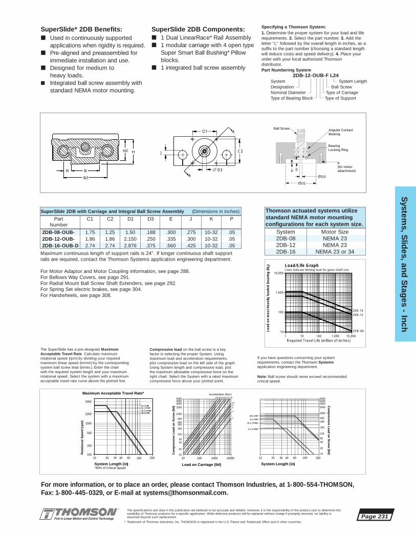
The specifications and data in this publication are believed to be accurate and reliable. However, it is the responsibility of the product user to determine thesuitability of Thomson products for a specific application. While defective products will be replaced without charge if promptly returned, no liability isassumed beyond such replacement.
* Trademark of Thomson Industries, Inc. THOMSON is registered in the U.S. Patent and Trademark Office and in other countries.
System
s, Slid
es, and S
tages - Inch
Page 231
For more information, or to place an order, please contact Thomson Industries, at 1-800-554-THOMSON, Fax: 1-800-445-0329, or E-mail at [email protected].
H2 H
B
B2
R
SuperSlide* 2DB Benefits:■ Used in continuously supported
applications when rigidity is required.■ Pre-aligned and preassembled for
immediate installation and use. ■ Designed for medium to
heavy loads.■ Integrated ball screw assembly with
standard NEMA motor mounting.
SuperSlide 2DB Components:■ 1 Dual LinearRace* Rail Assembly■ 1 modular carriage with 4 open type
Super Smart Ball Bushing* Pillow blocks.
■ 1 integrated ball screw assembly
Specifying a Thomson System:1. Determine the proper system for your load and liferequirements. 2. Select the part number. 3. Add the letter “L” followed by the overall length in inches, as asuffix to the part number (choosing a standard lengthwill reduce costs and speed delivery). 4. Place yourorder with your local authorized Thomson distributor.Part Numbering System
2DB-12-OUB-F L24System System LengthDesignation Ball ScrewNominal Diameter Type of CarriageType of Bearing Block Type of Support
Thomson actuated systems utilizestandard NEMA motor mountingconfigurations for each system size.
System Motor Size2DB-08 NEMA 232DB-12 NEMA 232DB-16 NEMA 23 or 34
SuperSlide 2DB with Carriage and Integral Ball Screw Assembly (Dimensions in inches)
Part C1 C2 D1 D3 E J K PNumber
2DB-08-OUB- 1.75 1.25 1.50 .188 .300 .275 10-32 .052DB-12-OUB- 1.86 1.86 2.150 .250 .335 .300 10-32 .052DB-16-OUB-D 2.74 2.74 2.876 .375 .560 .425 10-32 .05
Maximum continuous length of support rails is 24". If longer continuous shaft supportrails are required, contact the Thomson Systems application engineering department.
For Motor Adaptor and Motor Coupling information, see page 288.For Bellows Way Covers, see page 291.For Radial Mount Ball Screw Shaft Extenders, see page 292.For Spring Set electric brakes, see page 304.For Handwheels, see page 308.
P
D3
D1
K
E
BearingLocking Ring
Angular ContactBearing
Ball Screw
(for motor attachment)
C2J
D3
A
A
The SuperSlide has a pre-designed MaximumAcceptable Travel Rate. Calculate maximumrotational speed (rpm) by dividing your requiredmaximum linear speed (in/min) by the corresponding system ball screw lead (in/rev.). Enter the chartwith the required system length and your maximum rotational speed. Select the system with a maximumacceptable travel rate curve above the plotted line.
Compressive load on the ball screw is a keyfactor in selecting the proper System. Using maximum load and acceleration requirements, plot compressive load on the left side of the graph.Using System length and compressive load, plot the maximum allowable compressive force on the right chart. Select the System with a rated maximumcompressive force above your plotted point.
If you have questions concerning your systemrequirements, contact the Thomson Systemsapplication engineering department.
Note: Ball screw should never exceed recommended critical speed.
Maximum Acceptable Travel Rate*
10010 20 30 40 60 100
System Length (in)*80% of Critical Speed
5000
1000
2000
200
500
Ro
tati
on
al S
pee
d (
rpm
)
200
20 x 5 NP
.5x .2 P/NP
.75 x 2 P/NP
12 x 5 NP
20 x 5 NP
12 x 5 NP
.75 x .2 P/NP
.5 x .2 P/NP
1000
2000300040005000
100
200
400600
Co
mp
ressive Lo
ad o
n S
crew (lb
f)
System Length (in)
6040
20
10
10 20 30 40 60 100 200
Co
mp
ress
ive
Lo
ad o
n S
crew
(lb
f)
100 1000 1000010
1000
2000300040005000
100
200300400600
Load on Carriage (lbf)
Acceleration (ft/s2)
10
68
4
2
60
100 6080 40 30 20
40
20
10
Load/Life GraphLines indicate limiting load for given shaft size
Load
on
mo
st h
eavi
ly lo
aded
bea
ring
(lb
f)
110
10
100
100
1,000
1,000
10,000
10,000
Required Travel Life (million of inches)
2DB-08
2DB-162DB-12
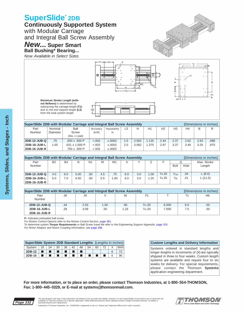
Page 232The specifications and data in this publication are believed to be accurate and reliable. However, it is the responsibility of the product user to determine thesuitability of Thomson products for a specific application. While defective products will be replaced without charge if promptly returned, no liability isassumed beyond such replacement.
* Trademark of Thomson Industries, Inc. THOMSON is registered in the U.S. Patent and Trademark Office and in other countries.
Sys
tem
s, S
lides
, and
Sta
ges
- I
nch
For more information, or to place an order, please contact Thomson Industries, at 1-800-554-THOMSON, Fax: 1-800-445-0329, or E-mail at [email protected].
SuperSlide* 2DBContinuously Supported Systemwith Modular Carriage and Integral Ball Screw Assembly
System 18 24 30 36 42 48 54 60 72 X MAX2DB-12 ■ ■ ■ ■ ■ ■ 6 722DB-16 ■ ■ ■ ■ ■ ■ ■ ■ ■ 6 96
SuperSlide System 2DB Standard Lengths (Lengths in inches) Custom Lengths and Delivery Information
Systems ordered in standard lengths andlonger lengths in increments of (X) are typicallyshipped in three to four weeks. Custom lengthsystems are available and require four to sixweeks for delivery. For special requirements,please contact the Thomson Systems application engineering department.
SuperSlide 2DB with Modular Carriage and Integral Ball Screw Assembly (Dimensions in inches)
Maximum Stroke Length (with-out Bellows) is determined bysubtracting the carriage length (T1)and 2x the end support length (L3)from the total system length.
2DB-12-JUB-Q .75 .500 x .500 P <.002 ±.0002 1.5 2.562 1.125 2.44 2.37 2.62 2.63 .6882DB-16-JUB-L 1.00 .631 x 1.000 P <.002 ±.0002 2.0 3.062 1.375 2.97 3.37 3.49 3.25 .8752DB-16-JUB-R .750 x .500 P <.002 ±.0002
Part Nominal Ball Accuracy Repeatability L3 H H1 H2 H3 H4 B RNumber Diameter Screw (in/ft) in
(Dia. x Lead)
SuperSlide 2DB with Modular Carriage and Integral Ball Screw Assembly (Dimensions in inches)
2DB-12-JUB-Q 4.0 6.0 5.00 .50 4.5 .75 6.0 3.0 1.00 1/4-20 5/16 .34 L-(9.0)
2DB-16-JUB-L 5.0 7.0 6.50 .50 5.5 1.00 6.0 3.0 1.25 1/4-20 3/8 .41 L-(11.5)
2DB-16-JUB-R
Part B2 B4 N N1 M M1 X Y Z F G Max. StrokeNumber Bolt Hole Length
SuperSlide 2DB with Modular Carriage and Integral Ball Screw Assembly (Dimensions in inches)
2DB-12-JUB-Q .44 2.53 1.00 .95 1/4-20 6.000 6.0 .502DB-16-JUB-L .28 3.09 .50 1.33 1/4-20 7.500 7.5 .502DB-16-JUB-R
Part J8 J9 V W F1 T T1 H6Number
Y X F
NT1
N1
M1
M
Z
G
L
L3
H3
New... Super SmartBall Bushing* Bearing...Now Available in Select Sizes
M1
J9
W M
N T1
F1
J8
N1
V
P- Indicates preloaded ball screw.For Motion Control Options refer to the Motion Control Section, page 381.To determine system Torque Requirements or Ball Screw travel life refer to the Engineering Support Appendix, page 310.For Motor Adaptor and Motor Coupling information, see page 288.

The specifications and data in this publication are believed to be accurate and reliable. However, it is the responsibility of the product user to determine thesuitability of Thomson products for a specific application. While defective products will be replaced without charge if promptly returned, no liability isassumed beyond such replacement.
* Trademark of Thomson Industries, Inc. THOMSON is registered in the U.S. Patent and Trademark Office and in other countries.
System
s, Slid
es, and S
tages - Inch
Page 233
For more information, or to place an order, please contact Thomson Industries, at 1-800-554-THOMSON, Fax: 1-800-445-0329, or E-mail at [email protected].
Superslide* 2DB Benefits:■ Used in continuously supported
applications when rigidity is required.■ Pre-aligned and preassembled for
immediate installation and use. ■ Designed for medium to heavy
loads.■ Integrated ball screw assembly with
standard NEMA motor mounting.
Superslide 2DB Components:■ 1 Dual LinearRace* Rail Assembly■ 1 modular carriage with 4 open type
Super Smart Ball Bushing* Pillow blocks
■ 1 integrated ball screw assembly
Specifying a Thomson System:1. Determine the proper system for your load and liferequirements. 2. Select the part number. 3. Add theletter “L” followed by the overall length in inches, as asuffix to the part number (choosing a standard lengthwill reduce costs and speed delivery). 4. Place yourorder with your local authorized Thomson distributor.Part Numbering System
2DB-12-JUB-Q L24System System LengthDesignation Ball ScrewNominal Diameter Type of CarriageType of Bearing Block Type of Support
Thomson actuated systems utilizestandard NEMA motor mountingconfigurations for each system size.
System Motor Size2DB-12 NEMA 232DB-16 NEMA 23 or 34
Superslide 2DB with Modular Carriage and Integral Ball Screw Assembly (Dimensions in inches)
2DB-12-JUB-Q 1.86 1.86 2.15 .250 .335 .300 10-32 .052DB-16-JUB-L 2.74 2.74 2.876 .375 .560 .425 10-32 .052DB-16-JUB-R
Part C1 C2 D1 D3 E J K PNumber
H2
H1
R
B
B2
B1
H
H6
T
Maximum continuous length of support rails is 24". If longer continuous shaft supportrails are required, contact the Thomson Systems application engineering department.
For Bellows Way Covers, see page 291.For Radial Mount Ball Screw Shaft Extenders, see page 292.For Spring Set electric brakes, see page 304.For Handwheels, see page 308.
P
D3
D1
K
E
BearingLocking Ring
Angular ContactBearing
Ball Screw
(for motor attachment)
C2J
D3
C1 A
A
The SuperSlide has a pre-designed MaximumAcceptable Travel Rate. Calculate maximumrotational speed (rpm) by dividing your requiredmaximum linear speed (in/min) by the corresponding sys-tem ball screw lead (in/rev.). Enter the chartwith the required system length and your maximum rotational speed. Select the system with a maximumacceptable travel rate curve above the plotted line.
Compressive load on the ball screw is a keyfactor in selecting the proper System. Using maximum load and acceleration requirements, plot compressive load on the left side of the chart.Using System length and compressive load. plot the maximum allowable compressive force on the right chart. Select the System with a rated maximumcompressive force above your plotted point.
If you have questions concerning your systemrequirements, contact the Thomson Systemsapplication engineering department.
Note: Ball screw should never exceed recommended critical speed.
Maximum AcceptableTravel Rate*
10010 20 30 40 60 100
System Length (in)*80% of Critical Speed
5000
1000
2000
200
500
Ro
tati
ona
l Sp
eed
(rp
m)
200 100 1000 10000 100000 18 24 30 36 42 48 54 60 66 7210
10000
1000
2000
30004000
6000
100
200
300400600
Co
mp
ress
ive
Load
on
Scr
ew (l
bf)
Load on Carriage (lbf)
Acceleration (ft/s2)10 6 4
10000
1000
2000
30004000
6000
100
200
400
600
Co
mp
ressive Load
on S
crew (lb
f)
System Length (in)
80 8012
100 60 40 30
.5 x.5 P
.5x .5 P
.75x .5 P
.75 x.5 P
Load/Life GraphLines indicate limiting load for given shaft size
Lo
ad
on
mo
st h
ea
vily
loa
de
d b
ea
rin
g (
lbf)
110
10
100
100
1,000
1,000
10,000
10,000
Required Travel Life (million of inches)
2DB-08
2DB-162DB-12
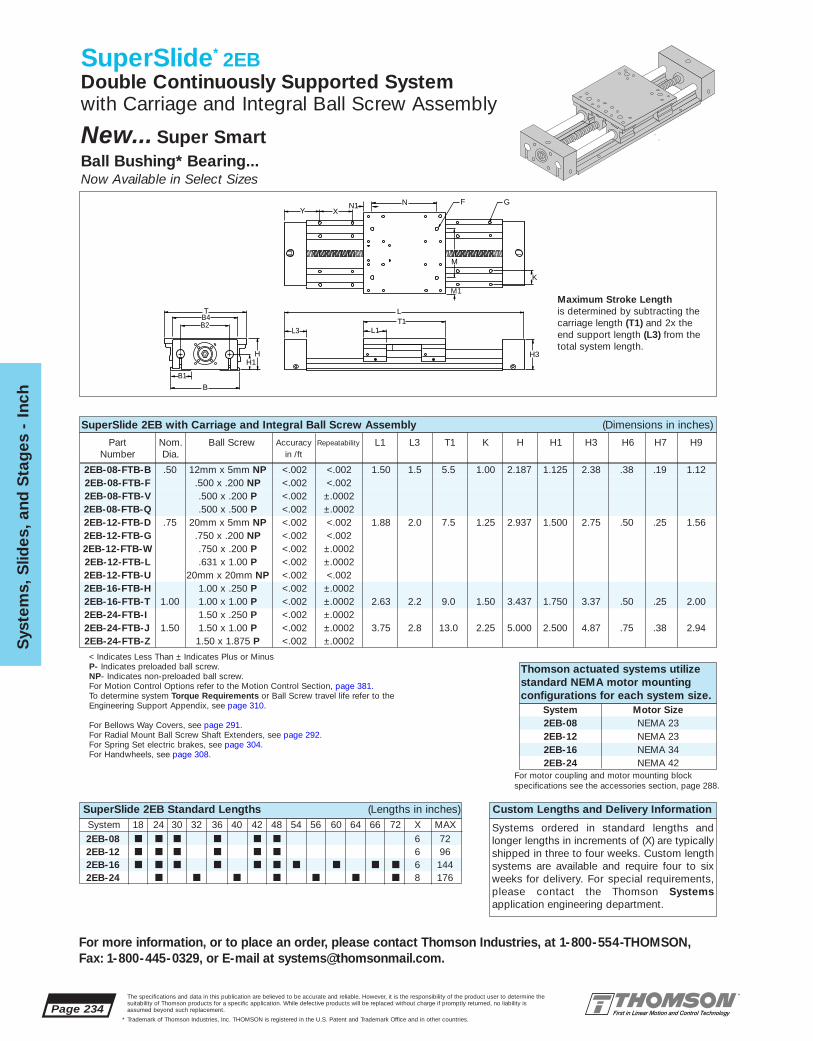
TB4
H
B2
B
B1
H1H3
L3 L1T1L
F
M1
M
K
GN1 N XY
Page 234The specifications and data in this publication are believed to be accurate and reliable. However, it is the responsibility of the product user to determine thesuitability of Thomson products for a specific application. While defective products will be replaced without charge if promptly returned, no liability isassumed beyond such replacement.
* Trademark of Thomson Industries, Inc. THOMSON is registered in the U.S. Patent and Trademark Office and in other countries.
Sys
tem
s, S
lides
, and
Sta
ges
- I
nch
For more information, or to place an order, please contact Thomson Industries, at 1-800-554-THOMSON, Fax: 1-800-445-0329, or E-mail at [email protected].
SuperSlide* 2EBDouble Continuously Supported Systemwith Carriage and Integral Ball Screw Assembly
New... Super SmartBall Bushing* Bearing...Now Available in Select Sizes
Custom Lengths and Delivery Information
Systems ordered in standard lengths andlonger lengths in increments of (X) are typicallyshipped in three to four weeks. Custom lengthsystems are available and require four to sixweeks for delivery. For special requirements,please contact the Thomson Systems application engineering department.
Maximum Stroke Lengthis determined by subtracting thecarriage length (T1) and 2x the end support length (L3) from thetotal system length.
SuperSlide 2EB with Carriage and Integral Ball Screw Assembly (Dimensions in inches)
Part Nom. Ball Screw Accuracy Repeatability L1 L3 T1 K H H1 H3 H6 H7 H9Number Dia. in /ft
Thomson actuated systems utilizestandard NEMA motor mountingconfigurations for each system size.
System Motor Size2EB-08 NEMA 232EB-12 NEMA 232EB-16 NEMA 342EB-24 NEMA 42
< Indicates Less Than ± Indicates Plus or MinusP- Indicates preloaded ball screw.NP- Indicates non-preloaded ball screw.For Motion Control Options refer to the Motion Control Section, page 381.To determine system Torque Requirements or Ball Screw travel life refer to theEngineering Support Appendix, see page 310.
For Bellows Way Covers, see page 291.For Radial Mount Ball Screw Shaft Extenders, see page 292.For Spring Set electric brakes, see page 304.For Handwheels, see page 308.
SuperSlide 2EB Standard Lengths (Lengths in inches)
For motor coupling and motor mounting blockspecifications see the accessories section, page 288.
System 18 24 30 32 36 40 42 48 54 56 60 64 66 72 X MAX2EB-08 ■ ■ ■ ■ ■ ■ 6 722EB-12 ■ ■ ■ ■ ■ ■ 6 962EB-16 ■ ■ ■ ■ ■ ■ ■ ■ ■ ■ 6 1442EB-24 ■ ■ ■ ■ ■ ■ ■ 8 176
2EB-08-FTB-B .50 12mm x 5mm NP <.002 <.002 1.50 1.5 5.5 1.00 2.187 1.125 2.38 .38 .19 1.122EB-08-FTB-F .500 x .200 NP <.002 <.0022EB-08-FTB-V .500 x .200 P <.002 ±.00022EB-08-FTB-Q .500 x .500 P <.002 ±.00022EB-12-FTB-D .75 20mm x 5mm NP <.002 <.002 1.88 2.0 7.5 1.25 2.937 1.500 2.75 .50 .25 1.562EB-12-FTB-G .750 x .200 NP <.002 <.0022EB-12-FTB-W .750 x .200 P <.002 ±.00022EB-12-FTB-L .631 x 1.00 P <.002 ±.00022EB-12-FTB-U 20mm x 20mm NP <.002 <.0022EB-16-FTB-H 1.00 x .250 P <.002 ±.00022EB-16-FTB-T 1.00 1.00 x 1.00 P <.002 ±.0002 2.63 2.2 9.0 1.50 3.437 1.750 3.37 .50 .25 2.002EB-24-FTB-I 1.50 x .250 P <.002 ±.00022EB-24-FTB-J 1.50 1.50 x 1.00 P <.002 ±.0002 3.75 2.8 13.0 2.25 5.000 2.500 4.87 .75 .38 2.942EB-24-FTB-Z 1.50 x 1.875 P <.002 ±.0002

The specifications and data in this publication are believed to be accurate and reliable. However, it is the responsibility of the product user to determine thesuitability of Thomson products for a specific application. While defective products will be replaced without charge if promptly returned, no liability isassumed beyond such replacement.
* Trademark of Thomson Industries, Inc. THOMSON is registered in the U.S. Patent and Trademark Office and in other countries.
System
s, Slid
es, and S
tages - Inch
Page 235
For more information, or to place an order, please contact Thomson Industries, at 1-800-554-THOMSON, Fax: 1-800-445-0329, or E-mail at [email protected].
SuperSlide* 2EB Benefits:■ Used in continuously supported
appli cations when rigidity is required. ■ Integrated ball screw assembly with
standard NEMA motor mounting.■ Pre-aligned and preassembled for
immediate installation and use.■ Designed for medium to heavy
loads.
SuperSlide 2EB Components:■ 4 open type Super Smart Ball
Bushing* pillow blocks■ 2 60 Case* LinearRace* Assemblies■ 2 integrated double end supports■ 1 mounting carriage top■ 1 integrated ball screw assembly
Specifying a Thomson System:1. Determine the proper system for your load and liferequirements. 2. Select the part number. 3. Add theletter “L” followed by the overall length in inches, as asuffix to the part number (choosing a standard lengthwill reduce costs and speed delivery). 4. Place yourorder with your local authorized Thomson distributor.Part Numbering System
2EB-12-FTB-G L24System System LengthDesignation Ball ScrewNominal Diameter Type of CarriageType of Bearing Block Type of Support
Load/Life GraphLines indicate limiting load for given shaft size
Load
on
mo
st h
eavi
ly lo
aded
bea
ring
(lb
f)
110
10
100
100
1,000
1,000
10,000
10,000
Required Travel Life (million of inches)
2EB-08
2EB-24
2EB-162EB-12
Determining the SuperSlide Systemfor your application:To determine the System which best meetsyour needs, calculate travel life vs. loadbased on your application criteria. Calculatethe load on the most heavily loaded bearingand total travel life requirements from stroke length and duty cycle. Select the system witha rated load life above your plotted point.
SuperSlide 2EB with Carriage and Integral Ball Screw Assembly (Dimensions in inches)Part T B R B1 B2 B4 N N1 M M1 X Y F G Max.
Number Bolt Hole StrokeLength
Maximum continuous length of support rails is 24". If longer continuous shaft support rails are required, contact the Thomson Systems application engineering department.
2EB-08-FTB-B 5.5 4.75 .750 1.50 3.25 4.25 4.5 .50 3.25 1.13 4.0 2.0 1/4-20 #8 .19 L-(8.5)2EB-08-FTB-F2EB-08-FTB-V2EB-08-FTB-Q2EB-12-FTB-D 7.5 6.25 .875 1.75 4.50 6.00 6.0 .75 4.50 1.50 6.0 3.0 5/16-18 #10 .22 L-(11.5)2EB-12-FTB-G2EB-12-FTB-W2EB-12-FTB-L2EB-12-FTB-U2EB-16-FTB-H 9.0 7.63 1.062 2.12 5.50 7.25 7.0 1.00 5.50 1.75 6.0 3.0 3/8-16 1/4 .28 L-(13.4)2EB-16-FTB-T2EB-24-FTB-I2EB-24-FTB-J 13.0 11.00 1.500 3.00 8.00 10.75 10.0 1.50 8.00 2.50 8.0 4.0 1/2-13 5/16 .34 L-(18.6)2EB-24-FTB-Z
The SuperSlide has a pre-designed MaximumAcceptable Travel Rate. Calculate maximumrotational speed (rpm) by dividing your requiredmaximum linear speed (in/min) by the corresponding system ball screw lead (in/rev.). Enter the chartwith the required system length and your maximum rotational speed. Select the system with a maximumacceptable travel rate curve above the plotted line.
Compressive load on the ball screw is a keyfactor in selecting the proper System. Using maximum load and acceleration requirements, plot compressive load on the left side of the chart.Using System length and compressive load. plot the maximum allowable compressive force on the right chart. Select the System with a rated maximumcompressive force above your plotted point.
If you have questions concerning your systemrequirements, contact the Thomson Systemsapplication engineering department.
Note: Ball screw should never exceed recommended critical speed.
Maximum AcceptableTravel Rate*
10010 20 30 40 60 100
System Length (in)*80% of Critical Speed
5000
1000
2000
200
500
Ro
tati
ona
l Sp
eed
(rp
m)
200 100 1000 10000 100000 18 24 30 36 42 48 54 60 66 7210
10000
1000
2000
30004000
6000
100
200
300400600
Co
mp
ress
ive
Load
on
Scr
ew (l
bf)
Load on Carriage (lbf)
Acceleration (ft/s2)10 6 4
10000
1000
2000
30004000
6000
100
200
400
600
Co
mp
ressive Load
on S
crew (lb
f)
System Length (in)
80 8012
100 60 40 30
20 x 20 NP
12 x 5 NP.5 x .2 P/NP.5 X .5 P
20 x 5 NP.75 x .2 P/NP
1 x 1 P1 x .25 P
1.5 x 1 P1.5 x 1.875 P
20 x 20 NP
20 x 5 NP12 x 5 NP
.5 x .2 P/NP
.75 x .2 P/NP.5 X .5 P
1.5 x 1 P
1.5 x 1.875 P
1 x 1 P1 x .25 P

Page 236The specifications and data in this publication are believed to be accurate and reliable. However, it is the responsibility of the product user to determine thesuitability of Thomson products for a specific application. While defective products will be replaced without charge if promptly returned, no liability isassumed beyond such replacement.
* Trademark of Thomson Industries, Inc. THOMSON is registered in the U.S. Patent and Trademark Office and in other countries.
Sys
tem
s, S
lides
, and
Sta
ges
- I
nch
For more information, or to place an order, please contact Thomson Industries, at 1-800-554-THOMSON, Fax: 1-800-445-0329, or E-mail at [email protected].
Ball Screw Assemblies
Ball Screw Assembly Standard Lengths (Lengths in inches)Part No. 18 24 30 32 36 40 42 48 54 60 64 66 72 80 84 88 96BSA-08-Q ■ ■ ■ ■ ■ ■
BSA-12-L ■ ■ ■ ■ ■ ■ ■ ■ ■ ■
BSA-16-H ■ ■ ■ ■ ■ ■ ■ ■ ■ ■ ■ ■
BSA-16-T ■ ■ ■ ■ ■ ■ ■ ■ ■ ■ ■ ■
BSA-24-I ■ ■ ■ ■ ■ ■ ■ ■ ■
BSA-24-J ■ ■ ■ ■ ■ ■ ■ ■ ■
BSA-24-Z ■ ■ ■ ■ ■ ■ ■ ■ ■
Ball Screw Assemblies - (Preloaded) (Dimensions in inches)Part Ball Screw Y V1 W W1 F3 L9 A A1 A5 A7 Motor
Number Dia. x Lead Frame Size
BSA-08-Q .500 x .500 1.00 0.25 0.95 0.14 #6-32 1.23 1.20 0.23 0.76 NEMA 23BSA-12-L .631 x 1.00 1.93 0.25 1.33 0.18 #8-32 1.69 1.80 - - NEMA 23BSA-16-H 1.00 x .250 1.90 0.25 1.63 0.26 #10-32 2.15 2.03 0.44 2.12 NEMA 34BSA-16-T 1.00 x 1.00 NEMA 34BSA-24-I 1.50 x .250 NEMA 42BSA-24-J 1.50 x 1.00 2.00 0.41 2.00 0.37 1/4-20 2.75 3.25 0.63 2.25 NEMA 42BSA-24-Z 1.50 x 1.875 NEMA 42
Preloaded Ball Screw Assembliesare predesigned to match thebase to pillow block height of1CA, 1CB and 1CC linear guides.To utilize Ball Screw Assemblieswith other linear guides contact theThomson Systems applicationengineering department.
Custom Lengths and DeliveryInformation
Systems ordered in standard lengthsare typically shipped in three to fourweeks. Custom length systems areavailable and require four to six weeksfor delivery. For special requirements,please contact the Thomson Systemsapplication engineering department.
Ball Screw Assemblies - (Preloaded) (Dimensions in inches)
Part Ball Screw L3 L5 L6 L8 H H3 H1 B B3 B4 R GNumber Dia. x Lead
BSA-08-Q .500 x .500 1.50 0.75 0.38 2.25 1.812 2.35 1.200 3.80 3.20 2.50 1.900 0.19BSA-12-L .631 x 1.00 2.00 1.00 0.50 2.437 2.70 1.500 3.80 3.20 2.50 1.900 0.22BSA-16-H 1.00 x .250 2.20 1.20 0.50 2.40 2.937 3.45 1.750 5.00 4.20 3.50 2.500 0.28BSA-16-T 1.00 x 1.00BSA-24-I 1.50 x .250BSA-24-J 1.50 x 1.00 2.80 1.50 0.65 2.82 4.250 5.000 2.500 7.25 6.20 5.00 3.625 0.34BSA-24-Z 1.50 x 1.875
Ball Screw NutMounting Block Cross-Section
Ball Screw Assembly Preloaded
For Motion Control Options, refer to the Motion Control Section, see page 381.To determine system Torque Requirements of Ball Screw travel life refer to the Engineering Support Appendix, page 310.For Motor Adaptor and Motor Coupling information, see page 288.
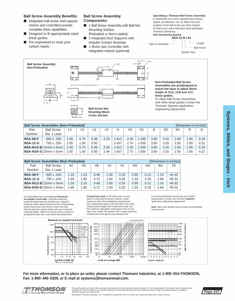
The specifications and data in this publication are believed to be accurate and reliable. However, it is the responsibility of the product user to determine thesuitability of Thomson products for a specific application. While defective products will be replaced without charge if promptly returned, no liability isassumed beyond such replacement.
* Trademark of Thomson Industries, Inc. THOMSON is registered in the U.S. Patent and Trademark Office and in other countries.
System
s, Slid
es, and S
tages - Inch
Page 237
For more information, or to place an order, please contact Thomson Industries, at 1-800-554-THOMSON, Fax: 1-800-445-0329, or E-mail at [email protected].
Specifying a Thomson Ball Screw Assembly:1. Determine your drive requirements (torque,speed, acceleration, etc. 2. Select the part number of the ball screw you have chosen. 3. Place your order with your local authorizedThomson distributor.Part Numbering System
BSA-12-B L24
Ball Screw AssemblyComponents:■ 1 Ball Screw Assembly with Ball Nut
Mounting Surface (Preloaded or Non-Loaded)
■ 2 Integrated End Supports withAngular Contact Bearings
■ 1 Motor and Controller with integrated indexer (optional)
Ball Screw Assembly Benefits:■ Integrated ball screw, end support,
motors and controllers provide complete drive capabilities.
■ Designed to fit appropriately sizedlinear guides.
■ Pre-engineered to meet your system needs.
Non-Preloaded Ball ScrewAssemblies are predesigned tomatch the base to pillow blockheight of 1CA, 1CB and 1CC linear guides.To utilize Ball Screw Assemblieswith other linear guides contact theThomson Systems applicationengineering department.
Ball Screw Assemblies (Non-Preloaded) (Dimension in inches)Part Ball Screw L3 L5 L6 L9 H H3 H1 B B3 B4 R G
Number Dia. x Lead
BSA-08-F .500 x .200 1.50 0.75 0.38 2.25 1.812 2.35 1.200 3.80 3.20 2.50 1.90 0.19BSA-12-G .750 x .200 2.00 1.00 0.50 2.437 2.70 1.500 3.80 3.20 2.50 1.90 0.22BSA-M12-B 12mm x 5mm 1.50 0.75 0.38 2.25 1.812 2.35 1.200 3.80 3.20 2.50 1.90 0.19BSA-M20-D 20mm x 5mm 2.00 1.00 0.50 2.46 2.437 2.70 1.500 3.80 3.20 2.50 1.90 0.22
Ball Screw NutMounting Block Cross-Section
Ball Screw Assembly Non-Preloaded
Ball Screw Assemblies (Non-Preloaded) (Dimension in inches)Part Ball Screw A2 A3 A8 V2 V3 W2 W3 W4 F3
Number Dia. x Lead
BSA-08-F .500 x .200 1.19 1.23 0.48 1.00 0.25 0.95 0.12 1.19 #6-32BSA-12-G .750 x .200 1.69 1.80 0.72 1.93 0.25 1.33 0.18 1.69 #8-32BSA-M12-B 12mm x 5mm 1.19 1.23 0.48 1.00 0.25 0.95 0.12 1.19 #6-32BSA-M20-D 20mm x 5mm 1.69 1.80 0.72 1.93 0.25 1.33 0.18 1.69 #8-32
Type of Assembly Length
Ball Screw
System Size
The SuperSlide has a pre-designed MaximumAcceptable Travel Rate. Calculate maximumrotational speed (rpm) by dividing your requiredmaximum linear speed (in/min) by the corresponding system ball screw lead (in/rev.). Enter the chartwith the required system length and your maximum rotational speed. Select the system with a maximumacceptable travel rate curve above the plotted line.
Compressive load on the ball screw is a keyfactor in selecting the proper System. Using maximum load and acceleration requirements, plot compressive load on the left side of the chart.Using System length and compressive load. plot the maximum allowable compressive force on the right chart. Select the System with a rated maximumcompressive force above your plotted point.
If you have questions concerning your systemrequirements, contact the Thomson Systemsapplication engineering department.
Note: Ball screw should never exceed recommended critical speed.
Maximum AcceptableTravel Rate*
10010 20 30 40 60 100
System Length (in)*80% of Critical Speed
5000
1000
2000
200
500
Ro
tati
ona
l Sp
eed
(rp
m)
200 100 1000 10000 100000 18 24 30 36 42 48 54 60 66 7210
10000
1000
2000
30004000
6000
100
200
300400600
Co
mp
ress
ive
Load
on
Scr
ew (l
bf)
Load on Carriage (lbf)
Acceleration (ft/s2)10 6 4
10000
1000
2000
30004000
6000
100
200
400
600
Co
mp
ressive Load
on S
crew (lb
f)
System Length (in)
80 8012
100 60 40 30
12 x 5 NP.5 x .2 P/NP.5 X .5 P
20 x 5 NP
.75 x .2 P/NP
1 x 1 P1 x .25 P
1.5 x 1 P1.5 x 1.875 P
20 x 5 NP12 x 5 NP
.5 x .2 P/NP
.75 x .2 P/NP.5 X .5 P
1.5 x 1 P
1.5 x 1.875 P
1 x 1 P1 x .25 P
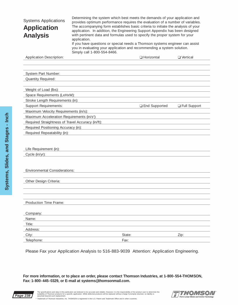
Page 238The specifications and data in this publication are believed to be accurate and reliable. However, it is the responsibility of the product user to determine thesuitability of Thomson products for a specific application. While defective products will be replaced without charge if promptly returned, no liability isassumed beyond such replacement.
* Trademark of Thomson Industries, Inc. THOMSON is registered in the U.S. Patent and Trademark Office and in other countries.
Sys
tem
s, S
lides
, and
Sta
ges
- I
nch
For more information, or to place an order, please contact Thomson Industries, at 1-800-554-THOMSON, Fax: 1-800-445-0329, or E-mail at [email protected].
Systems Applications
ApplicationAnalysis
Determining the system which best meets the demands of your application and provides optimum performance requires the evaluation of a number of variables. The accompanying form establishes basic criteria to initiate the analysis of your application. In addition, the Engineering Support Appendix has been designed with pertinent data and formulas used to specify the proper system for your application.If you have questions or special needs a Thomson systems engineer can assist you in evaluating your application and recommending a system solution. Simply call 1-800-554-8466.
Application Description: ❑ Horizontal ❑ Vertical
System Part Number:
Quantity Required:
Weight of Load (lbs):
Space Requirements (LxHxW):
Stroke Length Requirements (in):
Support Requirements: ❑ End Supported ❑ Full Support
Maximum Velocity Requirements (in/s):
Maximum Acceleration Requirements (in/s2):
Required Straightness of Travel Accuracy (in/ft):
Required Positioning Accuracy (in):
Required Repeatability (in):
Life Requirement (in):
Cycle (in/yr):
Environmental Considerations:
Other Design Criteria:
Production Time Frame:
Company:
Name:
Title:
Address:
City: State: Zip:
Telephone: Fax:
Please Fax your Application Analysis to 516-883-9039 Attention: Application Engineering.

The specifications and data in this publication are believed to be accurate and reliable. However, it is the responsibility of the product user to determine thesuitability of Thomson products for a specific application. While defective products will be replaced without charge if promptly returned, no liability isassumed beyond such replacement.
* Trademark of Thomson Industries, Inc. THOMSON is registered in the U.S. Patent and Trademark Office and in other countries.
System
s, Slid
es, and S
tages - M
etric
Page 239
For more information, or to place an order, please contact Thomson Industries, at 1-800-554-THOMSON, Fax: 1-800-445-0329, or E-mail at [email protected].
Systems, Slides, and Stages
Engineering Selection Guide forLinear Motion System Solutions
Metric Products
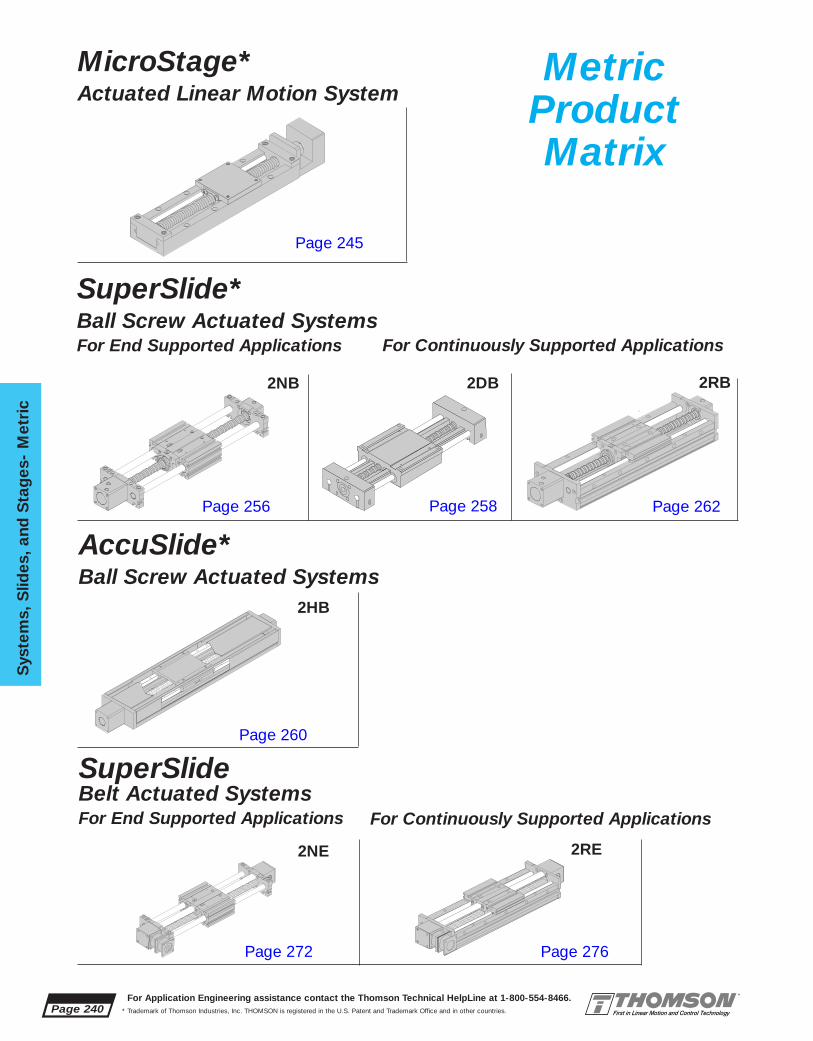
Page 240For Application Engineering assistance contact the Thomson Technical HelpLine at 1-800-554-8466.
* Trademark of Thomson Industries, Inc. THOMSON is registered in the U.S. Patent and Trademark Office and in other countries.
Sys
tem
s, S
lides
, and
Sta
ges
- M
etri
c
SuperSlide*Ball Screw Actuated SystemsFor End Supported Applications
MicroStage*Actuated Linear Motion System
AccuSlide*Ball Screw Actuated Systems
SuperSlideBelt Actuated SystemsFor End Supported Applications
For Continuously Supported Applications
For Continuously Supported Applications
2NB 2DB 2RB
2HB
2NE 2RE
Metric ProductMatrix
Page 245
Page 256 Page 258 Page 262
Page 260
Page 272 Page 276

The specifications and data in this publication are believed to be accurate and reliable. However, it is the responsibility of the product user to determine thesuitability of Thomson products for a specific application. While defective products will be replaced without charge if promptly returned, no liability isassumed beyond such replacement.
* Trademark of Thomson Industries, Inc. THOMSON is registered in the U.S. Patent and Trademark Office and in other countries.
System
s, Slid
es, and S
tages - M
etric
Page 241
For more information, or to place an order, please contact Thomson Industries, at 1-800-554-THOMSON, Fax: 1-800-445-0329, or E-mail at [email protected].
AccuSlide*Belt Actuated Systems
2HE
Turbo Module*Belt Actuated Systems
2GE
MetricProductMatrix
Page 279
Page 274

Page 242The specifications and data in this publication are believed to be accurate and reliable. However, it is the responsibility of the product user to determine thesuitability of Thomson products for a specific application. While defective products will be replaced without charge if promptly returned, no liability isassumed beyond such replacement.
* Trademark of Thomson Industries, Inc. THOMSON is registered in the U.S. Patent and Trademark Office and in other countries.
Sys
tem
s, S
lides
, and
Sta
ges
- M
etri
c
For more information, or to place an order, please contact Thomson Industries, at 1-800-554-THOMSON, Fax: 1-800-445-0329, or E-mail at [email protected].
Product Selector
MicroStage* Actuated Linear Motion Systemsfor lightly loaded, smooth travel applications
The MicroStage system incorporates a unique bearing segment design that offerssmooth anti-friction linear motion in a very compact envelope for applicationswhere high precision in a tight space are absolute requirements. The lead screwactuated stage is available in two different nominal sizes of 25mm and 33mm over-all carriage mounting surface height. The lead screw is offered in both inch and met-ric dimensions with leads ranging from .025 inches to 1.2 inches and 1mm to 3mm.The slide is standard with a motor coupling and motor adapter block. The motormounting arrangements are to recognized industry standards or custom stepper orservo motors can be configured to meet your needs. A standardized bolt hole pat-tern in the base assembly and on the carriage top as well as T-slots on the size 33system allow for easy interchange and simple X-Y mounting. A range of standardoverall lengths for each size stage is offered, while custom lengths can be accom-modated. (Refer to page 245).
AccuSlide* Ball Screw Actuated Systemsfor high load, tight precision continuously supported applications
AccuSlide Ball Screw Actuated Systems are continuously supported linear motionsystems complete with pre-aligned ProfileRail* linear guides and an integral ballscrew assembly. The load bearing members on the AccuSlide system are theAccuGlide* linear guides which provide high precision, tight tolerance positioningon a modular base assembly with T-slot mounting. A uniquely designed carriageprovides a bolt hole mounting pattern on pedestal table mounts which allow for anoptional shroud cover that protects the moving elements from contamination withno stroke reduction and provides easy workpiece mounting. Integral ball screwassemblies are available in a wide range of diameters and leads for the most strin-gent motion control requirements. The motor end block is designed forindustry standard servo motors to adapt directly to the system with only the use ofa shaft coupling. Once the AccuSlide system has been selected, simply specify astandard Thomson AXI-PAK* motion control package for a complete turnkeymotion control solution. (Refer to page 260).
AccuSlide Belt Driven Systemsfor high load, high speed continuously supported applications
AccuSlide Belt Driven Systems are continuously supported linear motion systems complete with pre-aligned ProfileRail linear guides and an integral belt driveassembly. The load bearing members on the AccuSlide system are the AccuGlidelinear guides which provide high precision, tight tolerance positioning on a modular base assembly with T-slot mounting. A uniquely designed carriage provides a bolt hole mounting pattern on pedestal table mounts which allow for anoptional shroud cover that protects the moving elements from contamination withno stroke reduction and provides easy workpiece mounting. A Thomson MicronNemaTRUE* Planetary* gearhead provides speed reduction, torque multiplicationand inertia matching and mounts directly to industry standard servo motors. Oncethe AccuSlide system has been selected, simply specify a standard Thomson AXI-PAK motion control package for a complete turnkey motion control solution.(Refer to page 274).

The specifications and data in this publication are believed to be accurate and reliable. However, it is the responsibility of the product user to determine thesuitability of Thomson products for a specific application. While defective products will be replaced without charge if promptly returned, no liability isassumed beyond such replacement.
* Trademark of Thomson Industries, Inc. THOMSON is registered in the U.S. Patent and Trademark Office and in other countries.
System
s, Slid
es, and S
tages - M
etric
Page 243
For more information, or to place an order, please contact Thomson Industries, at 1-800-554-THOMSON, Fax: 1-800-445-0329, or E-mail at [email protected].
Product Selector
SuperSlide* Ball Screw Actuated Systemsfor End and Continuously Supported Applications
SuperSlide Belt Actuated Systemsfor End and Continuously Supported Applications
SuperSlide Ball Screw Actuated Systems are available in an end and continuously supported version complete with prealigned LinearRace* ways and an integral ballscrew assembly. Uniquely designed carriages and LinearRace assemblies offer modularity with integrated T-slots for easy assembly and work piece mounting. AllSuperSlide Ball Screw Actuated Systems can be mounted in any direction and are standard with Super Smart Ball Bushing* bearings which provide up to 216 times thetravel life of conventional linear bearing based systems. A uniquely designed lubrication system is available for all SuperSlide systems which disperses the properamount of lubrication to the system. Integral ball screw assemblies are available in awide range of diameters and leads and are designed to meet the most stringentmotion control requirements. Once the SuperSlide system has been selected simplyspecify a standard Axi-Pak* Motion Control package and your motion control needsare complete. (Refer to page 262).
This belt drive system is available with uniquely designed carriages and LinearRaceassemblies which offer modularity with integral T-slots for easy assembly and workpiece mounting. The steel cable reinforced tooth belt provides high speed andacceleration combined with good positioning accuracy and repeatability. AllSuperSlide Belt Actuated Systems offer the Super Smart Ball Bushing bearings whichprovide up to six times the load capacity of conventional linear bearing based systems. An anodized coating, double acting integral wipers combined with a uniquely designed lubrication system maximizes system reliability. A standard precision gearhead provides needed inertia matching and torque multiplication. Thegearheads True Planetary* design provides thrust capacity up to 1400 Nm at speedsas high as 4000 RPM. To specify all that is required is the system diameter and length.Once the SuperSlide Belt Actuated system has been selected, simply specify thestandard Axi-Pak Motion Control package that meets your application needs. (Refer to page 276).
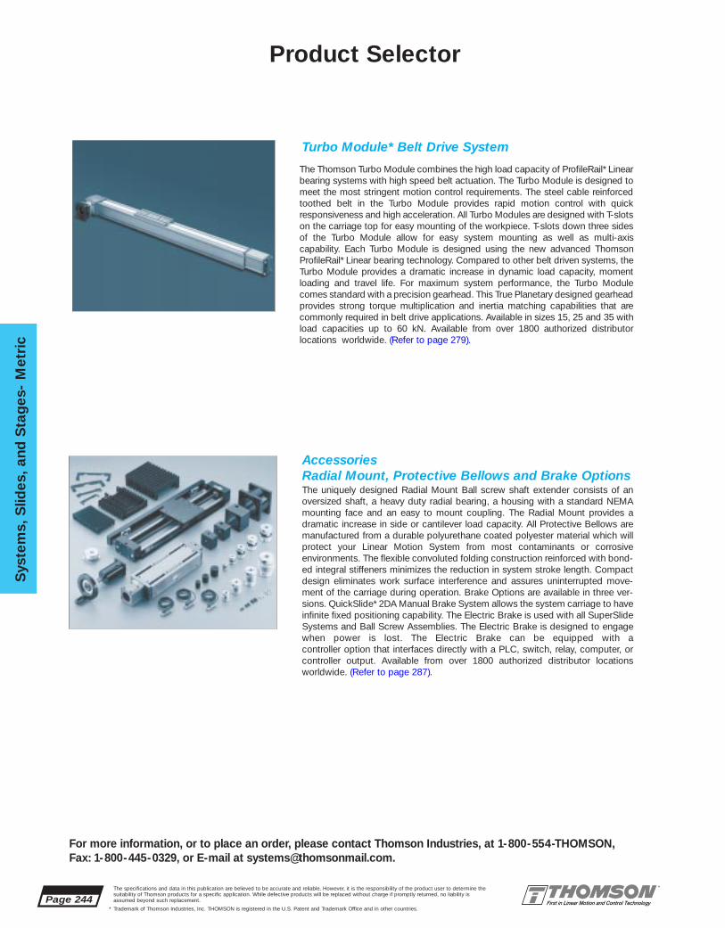
Page 244The specifications and data in this publication are believed to be accurate and reliable. However, it is the responsibility of the product user to determine thesuitability of Thomson products for a specific application. While defective products will be replaced without charge if promptly returned, no liability isassumed beyond such replacement.
* Trademark of Thomson Industries, Inc. THOMSON is registered in the U.S. Patent and Trademark Office and in other countries.
Sys
tem
s, S
lides
, and
Sta
ges
- M
etri
c
For more information, or to place an order, please contact Thomson Industries, at 1-800-554-THOMSON, Fax: 1-800-445-0329, or E-mail at [email protected].
Turbo Module* Belt Drive System
The Thomson Turbo Module combines the high load capacity of ProfileRail* Linearbearing systems with high speed belt actuation. The Turbo Module is designed tomeet the most stringent motion control requirements. The steel cable reinforcedtoothed belt in the Turbo Module provides rapid motion control with quick responsiveness and high acceleration. All Turbo Modules are designed with T-slotson the carriage top for easy mounting of the workpiece. T-slots down three sidesof the Turbo Module allow for easy system mounting as well as multi-axis capability. Each Turbo Module is designed using the new advanced ThomsonProfileRail* Linear bearing technology. Compared to other belt driven systems, theTurbo Module provides a dramatic increase in dynamic load capacity, momentloading and travel life. For maximum system performance, the Turbo Modulecomes standard with a precision gearhead. This True Planetary designed gearheadprovides strong torque multiplication and inertia matching capabilities that arecommonly required in belt drive applications. Available in sizes 15, 25 and 35 withload capacities up to 60 kN. Available from over 1800 authorized distributorlocations worldwide. (Refer to page 279).
AccessoriesRadial Mount, Protective Bellows and Brake OptionsThe uniquely designed Radial Mount Ball screw shaft extender consists of anoversized shaft, a heavy duty radial bearing, a housing with a standard NEMAmounting face and an easy to mount coupling. The Radial Mount provides a dramatic increase in side or cantilever load capacity. All Protective Bellows aremanufactured from a durable polyurethane coated polyester material which willprotect your Linear Motion System from most contaminants or corrosiveenvironments. The flexible convoluted folding construction reinforced with bond-ed integral stiffeners minimizes the reduction in system stroke length. Compactdesign eliminates work surface interference and assures uninterrupted move-ment of the carriage during operation. Brake Options are available in three ver-sions. QuickSlide* 2DA Manual Brake System allows the system carriage to haveinfinite fixed positioning capability. The Electric Brake is used with all SuperSlideSystems and Ball Screw Assemblies. The Electric Brake is designed to engagewhen power is lost. The Electric Brake can be equipped with a controller option that interfaces directly with a PLC, switch, relay, computer, orcontroller output. Available from over 1800 authorized distributor locationsworldwide. (Refer to page 287).
Product Selector
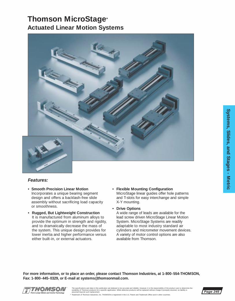
The specifications and data in this publication are believed to be accurate and reliable. However, it is the responsibility of the product user to determine thesuitability of Thomson products for a specific application. While defective products will be replaced without charge if promptly returned, no liability isassumed beyond such replacement.
* Trademark of Thomson Industries, Inc. THOMSON is registered in the U.S. Patent and Trademark Office and in other countries.
System
s, Slid
es, and S
tages - M
etric
Page 245
For more information, or to place an order, please contact Thomson Industries, at 1-800-554-THOMSON, Fax: 1-800-445-0329, or E-mail at [email protected].
• Smooth Precision Linear MotionIncorporates a unique bearing segmentdesign and offers a backlash-free slideassembly without sacrificing load capacity or smoothness.
• Rugged, But Lightweight ConstructionIt is manufactured from aluminum alloys toprovide the optimum in strength and rigidity,and to dramatically decrease the mass ofthe system. This unique design provides forlower inertia and higher performance versuseither built-in, or external actuators.
• Flexible Mounting ConfigurationMicroStage linear guides offer hole patternsand T-slots for easy interchange and simpleX-Y mounting.
• Drive OptionsA wide range of leads are available for the lead screw driven MicroStage Linear MotionSystem. MicroStage Systems are readilyadaptable to most industry standard air cylinders and micrometer movement devices.A variety of motor control options are alsoavailable from Thomson.
Features:
Thomson MicroStage*
Actuated Linear Motion Systems
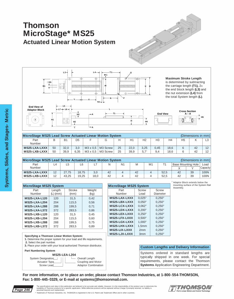
MS25-LXA-LXXX 12 27,75 18,75 3,0 42 4 42 4 52,5 42 39 100NMS25-LXB-LXXX 12 43,25 19,25 18,0 42 4 42 4 52,5 42 39 100N
MS25-LXA-LXXX 50 32,0 3,0 M3 x 0,5 M3 Screw 25 22,0 3,25 0,45 18,6 6 42 12MS25-LXB-LXXX 50 39,9 6,35 M3 x 0,5 M3 Screw 25 39,9 5,7† 9,4 18,6 6 42 12
MS25-LXA-L120 120 31,5 0,42MS25-LXA-L204 204 115,5 0,56MS25-LXA-L288 288 199,5 0,71MS25-LXA-L372 372 283,5 0,86MS25-LXB-L120 120 31,5 0,45MS25-LXB-L204 204 115,5 0,60MS25-LXB-L288 288 199,5 0,75MS25-LXB-L372 372 283,5 0,89
Page 246The specifications and data in this publication are believed to be accurate and reliable. However, it is the responsibility of the product user to determine thesuitability of Thomson products for a specific application. While defective products will be replaced without charge if promptly returned, no liability isassumed beyond such replacement.
* Trademark of Thomson Industries, Inc. THOMSON is registered in the U.S. Patent and Trademark Office and in other countries.
Sys
tem
s, S
lides
, and
Sta
ges
- M
etri
c
For more information, or to place an order, please contact Thomson Industries, at 1-800-554-THOMSON, Fax: 1-800-445-0329, or E-mail at [email protected].
MicroStage MS25 Lead Screw Actuated Linear Motion System (Dimensions in mm)Part B B1 D5 F G H H1 H2 H3 H4 H5 K L3
Number
MicroStage MS25 Lead Screw Actuated Linear Motion System (Dimensions in mm)Part L4 L5 L6 L7 N N1 M M1 T1 Base Mounting Hole Load
Number X Y Capacity
MicroStage MS25 SystemPart Length Stroke Weight
Number (L) (mm) (mm) (kg)
Thomson MicroStage* MS25Actuated Linear Motion System
L
T1
L6L7
L5
H
A
A
H4H2
H3
H1H5
Cross Section A – AEnd View
End View ofAdaptor Block
Maximum Stroke Lengthis determined by subtracting the carriage length (T1), 2xthe end block length (L3) andthe nut extension (L4) fromthe total System length (L).
K B B1
∅D5
Y XN 1
L 3
M
M 1
F
GT 1 L 4
N
Custom Lengths and Delivery Information
Systems ordered in standard lengths are typically shipped in one week. For specialrequirements, please contact the ThomsonSystems Application Engineering Department.
Specifying a Thomson Linear Motion System:1. Determine the proper system for your load and life requirements.2. Select the part number.
3. Place your order with your local authorized Thomson distributor.
Part Numbering System
MS25-LEA-L204System Designation Overall Length
Actuator Type Coupling and MotorScrew Lead Adaptor Combination
MicroStage MS25 SystemPart Screw Screw
Number Lead Diameter
MS25-LAX-LXXX 0,025" 0,250"MS25-LBX-LXXX 0,050" 0,250"MS25-LCX-LXXX 0,062" 0,250"MS25-LDX-LXXX 0,200" 0,250"MS25-LEX-LXXX 0,250" 0,250"MS25-LFX-LXXX 0,500" 0,250"MS25-LGX-LXXX 1,000" 0,250"MS25-LHX-LXXX 1,5mm 0,250"MS25-LIX-LXXX 2mm 0,250"MS25-LJX-LXXX 3mm 0,250"
† Adaptor Block extends below themounting surface of the System RailAssembly.

MS33-LXA-L200 200 100 0,95MS33-LXA-L300 300 200 1,25MS33-LXA-L400 400 300 1,56MS33-LXB-L200 200 100 1,07MS33-LXB-L300 300 200 1,37MS33-LXB-L400 400 300 1,68
MS33-LXA-LXXX 30 13 43,25 19,25 18,0 30 15 30 15 65 100 50 150NMS33-LXB-LXXX 30 13 39,75 17,75 14,0 30 15 30 15 65 100 50 150N
MS33-LXA-LXXX 60 39,9 8,0 4,2 2,75 2 6,35 M5 x 0,8 M5 Screw 33 39,9 1,05 8,45 25,5 7MS33-LXB-LXXX 60 57,66 8,0 4,2 2,75 2 6,35 M5 x 0,8 M5 Screw 33 57,66 7,83† 17,33 25,5 7
The specifications and data in this publication are believed to be accurate and reliable. However, it is the responsibility of the product user to determine thesuitability of Thomson products for a specific application. While defective products will be replaced without charge if promptly returned, no liability isassumed beyond such replacement.
* Trademark of Thomson Industries, Inc. THOMSON is registered in the U.S. Patent and Trademark Office and in other countries.
System
s, Slid
es, and S
tages - M
etric
Page 247
For more information, or to place an order, please contact Thomson Industries, at 1-800-554-THOMSON, Fax: 1-800-445-0329, or E-mail at [email protected].
MicroStage MS33 SystemPart Length Stroke Weight
Number (L) (mm) (mm) (kg)
Custom Lengths and Delivery Information
Systems ordered in standard lengths are typically shipped in one week. For specialrequirements, please contact the ThomsonSystems Application Engineering Department.
Specifying a Thomson Linear Motion System:1. Determine the proper system for your load and life requirements.2. Select the part number. 3. Place your order with your local authorized Thomson distributor.
Part Numbering System
MS33-LFB-L400System Designation Overall Length
Actuator Type Coupling and MotorScrew Lead Adaptor Combination
Thomson MicroStage* MS33Actuated Linear Motion System
L
T1Cross Section
A – AEnd View
H4H
H5A
A
D4
T-slots
D2
D3
D1End View of
Adaptor Block L6L7
L5
H2
H3
H1
Maximum Stroke Lengthis determined by subtracting the carriage length (T1) and 2x theend block length (L3) from thetotal Linear Guide length (L).
B K
Y X NN 1
M
M 1
F GT 1L 3
B1
∅D5
MicroStage MS33 SystemPart Screw Screw
Number Lead Diameter
MicroStage MS33 Lead Screw Actuated Linear Motion System (Dimensions in mm)Part B B1 D1 D2 D3 D4 D5 F G H H1 H2 H3 H4 H5
Number
MicroStage MS33 Lead Screw Actuated Linear Motion System (Dimensions in mm)Part K L3 L5 L6 L7 N N1 M M1 T1 Base Mounting Hole Load
Number X Y Capacity
† Adaptor Block extends below themounting surface of the System RailAssembly.
MS33-LAX-LXXX 0,0625" 0,375"MS33-LBX-LXXX 0,100" 0,375"MS33-LCX-LXXX 0,125" 0,375"MS33-LDX-LXXX 0,200" 0,375"MS33-LEX-LXXX 0,250" 0,375"MS33-LFX-LXXX 0,375" 0,375"MS33-LGX-LXXX 0,500" 0,375"MS33-LHX-LXXX 1,000" 0,375"MS33-LIX-LXXX 1,200" 0,375"MS33-LJX-LXXX 2mm 0,375"
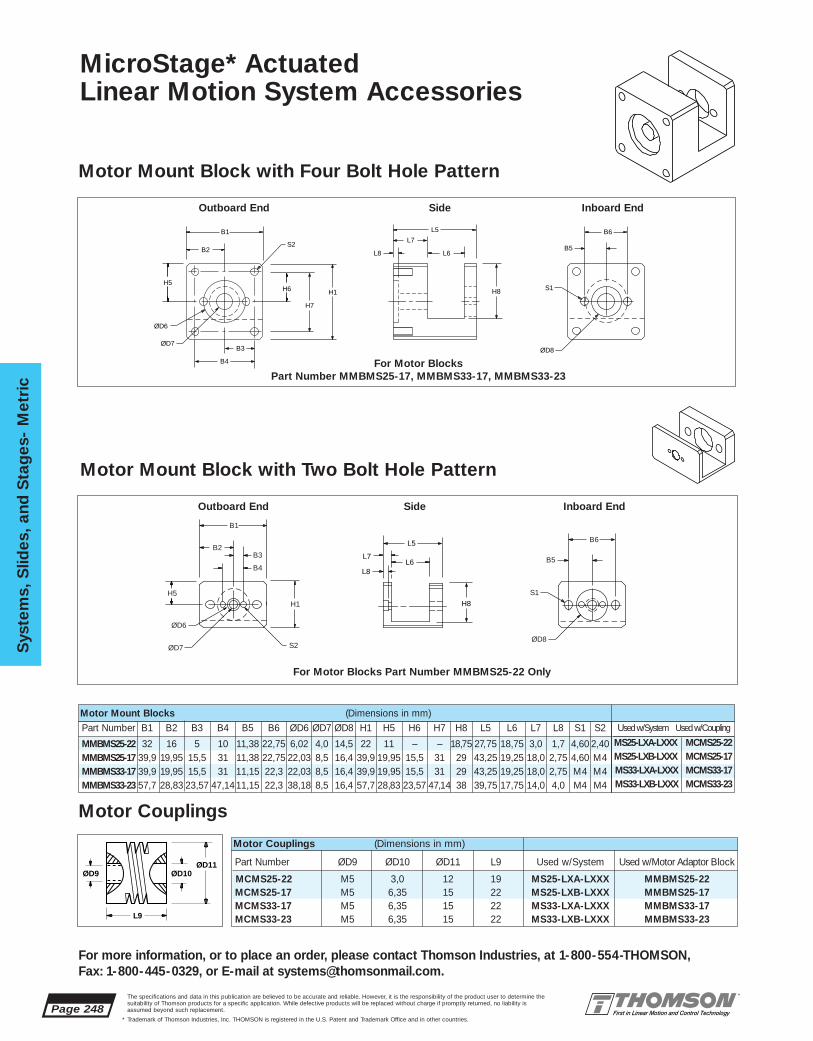
Part Number ØD9 ØD10 ØD11 L9 Used w/System Used w/Motor Adaptor Block
MCMS25-22 M5 3,0 12 19 MS25-LXA-LXXX MMBMS25-22MCMS25-17 M5 6,35 15 22 MS25-LXB-LXXX MMBMS25-17MCMS33-17 M5 6,35 15 22 MS33-LXA-LXXX MMBMS33-17MCMS33-23 M5 6,35 15 22 MS33-LXB-LXXX MMBMS33-23
Page 248The specifications and data in this publication are believed to be accurate and reliable. However, it is the responsibility of the product user to determine thesuitability of Thomson products for a specific application. While defective products will be replaced without charge if promptly returned, no liability isassumed beyond such replacement.
* Trademark of Thomson Industries, Inc. THOMSON is registered in the U.S. Patent and Trademark Office and in other countries.
Sys
tem
s, S
lides
, and
Sta
ges
- M
etri
c
For more information, or to place an order, please contact Thomson Industries, at 1-800-554-THOMSON, Fax: 1-800-445-0329, or E-mail at [email protected].
Motor Couplings (Dimensions in mm)
B1
S2B2
B4
L5
L6
L7
L8
B6
B5
B3
ØD6
ØD7ØD8
S1
H7
H8H6H5
H1
For Motor Blocks Part Number MMBMS25-17, MMBMS33-17, MMBMS33-23
MicroStage* Actuated Linear Motion System Accessories
Motor Mount Block with Four Bolt Hole Pattern
Motor Couplings
B1
S2
B2B6
B5B3
B4
ØD6
ØD7ØD8
S1H5H1
L5
L6L7
L8
H8
For Motor Blocks Part Number MMBMS25-22 Only
Motor Mount Block with Two Bolt Hole Pattern
Motor Mount Blocks (Dimensions in mm)Used w/System Used w/Coupling
MS25-LXA-LXXX MCMS25-22MS25-LXB-LXXX MCMS25-17MS33-LXA-LXXX MCMS33-17MS33-LXB-LXXX MCMS33-23
L9
ØD10ØD9ØD11
Outboard End Side Inboard End
Outboard End Side Inboard End
Part Number B1 B2 B3 B4 B5 B6 ØD6 ØD7 ØD8 H1 H5 H6 H7 H8 L5 L6 L7 L8 S1 S2
MMBMS25-22 32 16 5 10 11,38 22,75 6,02 4,0 14,5 22 11 – – 18,75 27,75 18,75 3,0 1,7 4,60 2,40MMBMS25-17 39,9 19,95 15,5 31 11,38 22,75 22,03 8,5 16,4 39,9 19,95 15,5 31 29 43,25 19,25 18,0 2,75 4,60 M4MMBMS33-17 39,9 19,95 15,5 31 11,15 22,3 22,03 8,5 16,4 39,9 19,95 15,5 31 29 43,25 19,25 18,0 2,75 M4 M4MMBMS33-23 57,7 28,83 23,57 47,1411,15 22,3 38,18 8,5 16,4 57,7 28,83 23,57 47,14 38 39,75 17,75 14,0 4,0 M4 M4

Rated Power† Watts 3Cont. Stall Torque† mNm 29.2No Load Speed† rpm 1500Resistance ohm 13.6Feedback – 2 channel 100 line encoderGear Ratio n:1 4.4
The specifications and data in this publication are believed to be accurate and reliable. However, it is the responsibility of the product user to determine thesuitability of Thomson products for a specific application. While defective products will be replaced without charge if promptly returned, no liability isassumed beyond such replacement.
* Trademark of Thomson Industries, Inc. THOMSON is registered in the U.S. Patent and Trademark Office and in other countries.
System
s, Slid
es, and S
tages - M
etric
Page 249
For more information, or to place an order, please contact Thomson Industries, at 1-800-554-THOMSON, Fax: 1-800-445-0329, or E-mail at [email protected].
Motors
22mm DC Gearmotor
Ø5
20
FLAT4.5
15
39,12
Ø22
4 x #4 – 404,32 Deep
31 sq.
41,9 sq.
305
MOUNTINGEND
Size 17 Step Motor
Ø21,98
Ø4,322 places
102,4
79,8
38,1
63
24,9
31
31
Ø6,35
1,5
39,9 sq.
Size 17 Brushless Servo Motor
Ø5,21 thru 4 holes equally spaced on 66,68 bolt circle
Ø38,1
39,9 sq.
141
11,7
51
116,8
20,1
Ø6,35
1,6
NEMA 23 Brushless Servo Motor
M2 x 3Dp2 places
Ø6
10
Ø16
Ø22 74,2
16 31,918,75
14,5
33,7Ø3
0,3
Parameter Units BRD22M715D10100
Parameter Units BLD1715D10100
Rated Power Watts 40Cont. Stall Torque Nm 0.20Peak Torque NM 0.55Inertia Kg-cm2 0.0275Torque Const. Nm/A 0.06Voltage Const. Vrms/krpm 6.47Feedback – 1000 line encoder & Halls
Parameter Units BLX232A2E000 BLX234A2E000
Rated Power Watts 160 360Cont. Stall Torque Nm 0.56 1.12Peak Torque NM 1.7 3.36Inertia Kg-cm2 0.109 .179Torque Const. Nm/A 0.204 0.204Voltage Const. Vrms/krpm 18.2 17.8Feedback – 2000 line commutating encoder
Parameter Units AMPHT17-071
Holding Torque oz-in 36.1Leads – 8Current amp 1.2Resistance ohm 3.3
† At gear box output

Page 250The specifications and data in this publication are believed to be accurate and reliable. However, it is the responsibility of the product user to determine thesuitability of Thomson products for a specific application. While defective products will be replaced without charge if promptly returned, no liability isassumed beyond such replacement.
* Trademark of Thomson Industries, Inc. THOMSON is registered in the U.S. Patent and Trademark Office and in other countries.
Sys
tem
s, S
lides
, and
Sta
ges
- M
etri
c
For more information, or to place an order, please contact Thomson Industries, at 1-800-554-THOMSON, Fax: 1-800-445-0329, or E-mail at [email protected].
Systems Applications
ApplicationAnalysis
Determining the system which best meets the demands of your application and provides optimum performance requires the evaluation of a number of variables. The accompanying form establishes basic criteria to initiate the analysis of your application. In addition, the Engineering Support Appendix has been designed with pertinent data and formulas used to specify the proper system for your application.If you have questions or special needs a Thomson systems engineer can assist you in evaluating your application and recommending a system solution. Simply call 1-800-554-8466.
Application Description: ❑ Horizontal ❑ Vertical
System Part Number:
Quantity Required:
Weight of Load (lbs):
Space Requirements (LxHxW):
Stroke Length Requirements (in):
Support Requirements: ❑ End Supported ❑ Full Support
Maximum Velocity Requirements (in/s):
Maximum Acceleration Requirements (in/s2):
Required Straightness of Travel Accuracy (in/ft):
Required Positioning Accuracy (in):
Required Repeatability (in):
Life Requirement (in):
Cycle (in/yr):
Environmental Considerations:
Other Design Criteria:
Production Time Frame:
Company:
Name:
Title:
Address:
City: State: Zip:
Telephone: Fax:
Please Fax your Application Analysis to 516-883-9039 Attention: Application Engineering

System
s, Slid
es, and S
tages - M
etric
Page 251
For more information, or to place an order, please contact Thomson Industries, at 1-800-554-THOMSON, Fax: 1-800-445-0329, or E-mail at [email protected].
The specifications and data in this publication are believed to be accurate and reliable. However, it is the responsibility of the product user to determine thesuitability of Thomson products for a specific application. While defective products will be replaced without charge if promptly returned, no liability isassumed beyond such replacement.
* Trademark of Thomson Industries, Inc. THOMSON is registered in the U.S. Patent and Trademark Office and in other countries.
SuperSlideBall Screw Actuated Systems
SuperSlide* Ball Screw ActuatedSystems offer:• An end supported and continuously
supported version complete with prealignedLinearRace* ways and an integral ball screwassembly. End Supported Systems are usedwhen spanning or bridging a gap.Continuously Supported Systems are usedwhen rigidity is required.
• Available with uniquely designed carriagesand LinearRace assemblies with integrated T-slots for easy assembly and mounting.
• Positioning accuracy better than 0,01 mmwith repeatability as low as 0,025 mm/300mm. Improvement in system performanceis realized immediately.
• Available with integrated Super Smart BallBushing* bearings which provide up to sixtimes the load capacity or 216 times the travellife of conventional linear bearing based systems.
• Anodized coating, double acting integral wipers and bellows for protection in corrosive environments. A uniquely designed lubricationsystem option is available for all systems.
• A variety of highly efficient ball screw assemblies with diameters and leadsdesigned to meet the most stringent motioncontrol requirements.
• A single part number system. All that is required to order is to specify the system nominal size and length.
• Easy integration to the Thomson AXI-PAK*motion control system. Once the Superslide system has been selected simply specify astandard Thomson Motion Control packagethat meets your complete motion controlneeds. (See the Motion Control Section on page 381)

Page 252
Sys
tem
s, S
lides
, and
Sta
ges
- M
etri
c
For more information, or to place an order, please contact Thomson Industries, at 1-800-554-THOMSON, Fax: 1-800-445-0329, or E-mail at [email protected].
The specifications and data in this publication are believed to be accurate and reliable. However, it is the responsibility of the product user to determine thesuitability of Thomson products for a specific application. While defective products will be replaced without charge if promptly returned, no liability isassumed beyond such replacement.
* Trademark of Thomson Industries, Inc. THOMSON is registered in the U.S. Patent and Trademark Office and in other countries.
60 Case* LinearRace* ways
External Accessory T-Slots in End Support
T-Slots in Carriage
System Support End Block
System 2NB Cross Section
Super Smart Ball Bushing bearing
Ball Screw Assembly
SuperSlide 2NB Ball Screw Actuated System Features:
• End Supported System • Long Travel Life
• Integral Ball Screw Assembly • Double Acting Wipers
• T-Slots in Carriage • Optional Lubrication System
• T-Slots in Base Mounting System • Speeds up to 1 m/s
• Positioning Accuracy is 0,025/300 mm • Single Part Number System
• Repeatability as Low as 0,01 mm • Standard Motor Mounting
• Super Smart Ball Bushing* bearing • Protective Bellows Option
SuperSlide* Ball Screw Actuated Systems
SuperSlide 2DB Ball Screw Actuated System Features:• Continuously Supported System • Load Capacities up to 33 kN
• Integral Ball Screw Assembly • Double Acting Wipers
• Drilled and Tapped Holes in Carriage • Optional Lubrication System
• Double Hole Spacing in Base • Speeds up to 1 m/s
• Positioning Accuracy is 0,025/300 mm • Single Part Number System
• Repeatability as Low as 0,01 mm • Standard Motor Mounting
• Super Smart Ball Bushing bearing • Protective Bellows Option
60 Case LinearRace ways
End Block
Carriage
Reference Edge
System 2DB Cross Section
Open Type Super SmartBall Bushing bearing
Ball Screw Assembly
System Support Base

System
s, Slid
es, and S
tages - M
etric
Page 253
For more information, or to place an order, please contact Thomson Industries, at 1-800-554-THOMSON, Fax: 1-800-445-0329, or E-mail at [email protected].
The specifications and data in this publication are believed to be accurate and reliable. However, it is the responsibility of the product user to determine thesuitability of Thomson products for a specific application. While defective products will be replaced without charge if promptly returned, no liability isassumed beyond such replacement.
* Trademark of Thomson Industries, Inc. THOMSON is registered in the U.S. Patent and Trademark Office and in other countries.
60 Case* LinearRace* ways
External Accessory T-Slots in Base
T-Slots in Carriage
System Support Base
System 2RB Cross Section
Open Type Super SmartBall Bushing* bearing
Ball Screw Assembly
Internal Accessory T-Slots in Base
AccuSlide* 2HB Ball Screw Driven System Features:• Continuously Supported System • Long travel life Capability
• Integral Ball Screw Assembly • Double Acting Seals
• T-Slots in Carriage • Optional Lubrication System
• AccuGlide* ProfileRail* system • Speeds up to 1 m/s
• Positioning Accuracy is 0,025/300 mm • Single Part Number System
• Repeatability as Low as 0,01 mm • Standard Motor Mounting
• Low Profile and Compact • Protective Bellows Option
AccuGlideProfileRail System
Carriage Mounting Sufaces
System Support Base
System 2HB Cross Section
Ball Screw Assembly
Anti-Contaminant Covers
Accessory T-Slots in Support Base
SuperSlide* Ball Screw Actuated Systems
SuperSlide 2RB Ball Screw Actuated System Features:• Continuously Supported System • Long Travel Life Capability
• Integral Ball Screw Assembly • Double Acting Wipers
• T-Slots in Carriage • Optional Lubrication System
• T-Slots in Base Mounting System • Speeds up to 1 m/s
• Positioning Accuracy is 0,025/300 mm • Single Part Number System
• Repeatability as Low as 0,01 mm • Standard Motor Mounting
• Super Smart Ball Bushing* bearing • Protective Bellows Option

Page 254
Sys
tem
s, S
lides
, and
Sta
ges
- M
etri
c
For more information, or to place an order, please contact Thomson Industries, at 1-800-554-THOMSON, Fax: 1-800-445-0329, or E-mail at [email protected].
The specifications and data in this publication are believed to be accurate and reliable. However, it is the responsibility of the product user to determine thesuitability of Thomson products for a specific application. While defective products will be replaced without charge if promptly returned, no liability isassumed beyond such replacement.
* Trademark of Thomson Industries, Inc. THOMSON is registered in the U.S. Patent and Trademark Office and in other countries.
Page 256
Page 258 Page 260 Page 262
SuperSlide*Ball Screw Actuated Systems
For End Supported Applications
SuperSlide Ball Screw Actuated SystemsSolution Matrix
For Continuously Supported Applications
2NB
2DB 2RB2HB
System
s, Slid
es, and S
tages - M
etric
Page 255
For more information, or to place an order, please contact Thomson Industries, at 1-800-554-THOMSON, Fax: 1-800-445-0329, or E-mail at [email protected].
The specifications and data in this publication are believed to be accurate and reliable. However, it is the responsibility of the product user to determine thesuitability of Thomson products for a specific application. While defective products will be replaced without charge if promptly returned, no liability isassumed beyond such replacement.
* Trademark of Thomson Industries, Inc. THOMSON is registered in the U.S. Patent and Trademark Office and in other countries.
SuperSlide* Ball Screw Actuated SystemsSelection Criteria
Many variables influence the selection of a Linear Motion System. The best solutiondemands a thorough evaluation of the application; only then can design criteria beestablished. Issues such as envelope limitations, system load capacity, actuator loadcapacity, speed and acceleration, drive requirements, accuracy and repeatability, andoperating environment are looked at from a broad perspective to determine the type ofsystem, type of actuator, and whether the system need be built of special materials.
Typically, a ball screw actuated linear motion system is ideal for tight precision, highlyrepeatable, high load, moderate speed applications. Long lead ball screws are availablefor most style systems, but it is important to be mindful of the critical speed (first harmonic of the resonant ball screw whirling vibration) in longer stroke systems whenattempting to reach higher linear velocities. If an application requires rigidity, then a fullysupported system should be specified in lieu of an end supported type system. Whenzero backlash is required for the best repeatability, then a preloaded version ball screwassembly need to be specified. For extremely heavy-duty applications, the AccuSlide*(2HB series) system, with its use of ProfileRail* type linear guides is adept at handlingnormal axis, overhung, or cantilever loads of increased magnitude. In environments thatare corrosive or high temperature special materials may be required and are available.Contact Application Engineering for details on special materials.
In order to determine the Ball Screw Actuated SuperSlide System that meets the needsof your application, it is first necessary to evaluate the following detail design criteria:
• System support requirements• System stroke length• Maximum allowable shaft deflection• Required travel life• Force on the most heavily loaded bearing• Load correction factor• Load/Life requirements-linear bearings• Load/Life requirements-ball screws• Motion (move) profile (velocity, acceleration)• Maximum acceptable travel rate• Torque considerations• Size motor using torque/speed curves
A detailed explanation of the procedure for selecting a Ball Screw Actuated LinearMotion System is given on page 327 in the Engineering Support Section.

2NB-M16 ■ ■ ■ ■ ■ ■ ■ ■ ■ ■ ■ ■ ■
2NB-M20 ■ ■ ■ ■ ■ ■ ■ ■ ■ ■
Page 256
Sys
tem
s, S
lides
, and
Sta
ges
- M
etri
c
For more information, or to place an order, please contact Thomson Industries, at 1-800-554-THOMSON, Fax: 1-800-445-0329, or E-mail at [email protected].
The specifications and data in this publication are believed to be accurate and reliable. However, it is the responsibility of the product user to determine thesuitability of Thomson products for a specific application. While defective products will be replaced without charge if promptly returned, no liability isassumed beyond such replacement.
* Trademark of Thomson Industries, Inc. THOMSON is registered in the U.S. Patent and Trademark Office and in other countries.
2NB-M16-OGL2NB-M20-OGL 66 34 65 60 20 75 31,5 M6 11,25 160 23
2NB-M16-OGL-G 16 16 x 5 P 0,025 ± 0,005 L-(000)2NB-M16-OGL-H 16 16 x 10 P 0,025 ± 0,0052NB-M20-OGL-I 20 20 x 5 P 0,025 ± 0,005 160 75 110 60 120 L-2002NB-M20-OGL-J 20 20 x 10 P 0,025 ± 0,0052NB-M20-OGL-K 20 20 x 20 P 0,025 ± 0,005
SuperSlide* 2NBEnd Supported Systemwith Integral Ball Screw Assembly and T-Slot Carriage
L
L4
H4
L3
T1
HH2
L3L5
H4
B2
B
H1
Maximum Stroke Lengthis determined by subtracting the carriage length (T1) and 2 times the end block length(L3) from the total systemlength (L).
SuperSlide 2NB System with Integral Ball Screw Assembly and T-Slot Carriage (Dimensions in mm)Part Nominal Ball Accuracy Repeatability B B1 B2 B3 B9 Max.
Number Dia. Screw mm/300 mm Stroke(Dia. x Lead) Length
SuperSlide 2NB System with Integral Ball Screw Assembly and T-Slot Carriage (Dimensions in mm)Part H H1 H2 H4 L3 L4 L5 N N1 T1 NEMA
Number Bolt Hole SIZE
New... Super SmartBall Bushing* Bearing...Now Available For All Sizes
Custom Lengths and Delivery InformationSystems ordered in standard lengths and longerlengths in increments of (X) are typically shipped intwo to three weeks. Custom length systems are avail-able and require three to four weeks for delivery. Forspecial requirements, please contact the ThomsonSystems application engineering department.
B1 B3 B 3
N/N1
System 2NB Standard Lengths (Lengths in mm)System 300 375 400 450 500 525 600 675 700 750 800 825 900 975 1000 1050 1100 11251200
■ ■ ■ ■ 75 1500■ ■ ■ 100 2000
1275 1300 1350 1400 1425 1500 X MAX
For Motion Control Options refer to the Motion Control Section on page 381.For Motor Coupling specifications, see page 290.For Bellows Way Covers, see page 291.For Radial Mount Ball Screw Shaft Extenders, see page 292.For Spring Set electric brakes, see page 304.For TNUT mounting hardware, see page 308.

System
s, Slid
es, and S
tages - M
etric
Page 257
For more information, or to place an order, please contact Thomson Industries, at 1-800-554-THOMSON, Fax: 1-800-445-0329, or E-mail at [email protected].
The specifications and data in this publication are believed to be accurate and reliable. However, it is the responsibility of the product user to determine thesuitability of Thomson products for a specific application. While defective products will be replaced without charge if promptly returned, no liability isassumed beyond such replacement.
* Trademark of Thomson Industries, Inc. THOMSON is registered in the U.S. Patent and Trademark Office and in other countries.
2NB-M16-OGL2NB-M20-OGL 8,1 16,5 6,8 3 8,1 16,5 6,8 4,5 66 63,5 19 32 15 160
2NB-M16-OGL 162NB-M20-OGL 20 75 120 20 120 20 120 6 10,5 4 3
SuperSlide* 2NB Benefits:■ Used in end supported applica-
tions when spanning or bridginga gap is required.
■ Single part number is all that is required
■ T-Slot in carriage provides quickand easy mounting and removal of the workpiece.
Specifying a Thomson System:1. Determine the proper system for your load and liferequirements. 2. Select the part number. 3. Add the letter “L” followed by the overall length in millimeters, asa suffix to the part number (choosing a standard lengthwill reduce costs and speed delivery). 4.Place yourorder with your local authorized Thomson distributor.Part Numbering System
2NB-M16-OGL-I L600System SystemDesignation LengthNominal Diameter Type of Ball Screw
Type of Carriage
Type of Support
SuperSlide 2NB System with Integral Ball Screw Assembly and T-Slot Carriage (Dimensions in mm)
SuperSlide 2NB System with Integral Ball Screw Assembly and T-Slot Carriage (Dimensions in mm)
Part Nominal B1 B4 B5 B6 B7 B9 D1 D2 D3 D4Number Diameter
Part E1 E2 E3 E4 E5 E6 E7 E8 H H3 H5 H6 H7 TNumber
SuperSlide 2NB Components:■ 2 LinearRace* End Support blocks
with T-Slots for mounting ease.■ 1 T-Slot integrated carriage with
4 Super Smart open type BallBushing* bearings.
■ 1 Integral Ball Screw Assembly
B6
B5
H3
B4T
HH6
H7
B7
T6
T6
T4
T6
T5
T6
T4
T5B9
C3
C3
H5
B1
T6
T6
T4T4
N/N1
D1
D3D4
D2
E6
E5E8
E7E1
E2E3
E4
End Block
T4 T-Slots T5 T-Slots T6 T-Slots
Carriage X-Section
Load/Life GraphLines indicate limiting load for given shaft size
Lo
ad o
n m
ost
hea
vily
load
ed b
eari
ng
(N
)
1010
100
100
1 000
1 000
10 000
10 000
100 000
Required Travel Life (km)
2NB-M16
2NB-M302NB-M40
2NB-M25
2NB-M20
2NB-M12
Maximum AcceptableTravel Rate✝
5000
1000
500
System Length (mm)✝80% of Critical Speed
400 1000 2000
Ro
tati
ona
l Sp
eed
(rev
/min
)
Compressive Load
10000
1000
500
Co
mp
ress
ive
Load
on
Scr
ew (N
)
10 100
1000
2000
Mass on Carriage (kg)
Acceleration (m/s2)30 20 10
8
65
4
3
2
1
16 x 5 P, 16 x 10P
1003000
100
16 x 5 P, 16 x 10P, 16 x 16P
25 x 5 P, 25 x 10 P, 25 x 25 P
20 x 5 P, 20 x 10 P, 20 x 20 P
16 x 5 P
25 x 5 P
25 x 10 P
20 x 20 P20 x 5 P
25 x 25 P
Maximum AllowableCompressive Load
10000
1000
500
Max
imum
Allo
wab
le C
om
pre
ssiv
e Lo
ad (N
)
1000
System Length (mm)
100
100 2000 3000
16 x 10 P16 x 16 P
20 x 10 P
100 000
50 000
20 000
10 000
5 000
2 000
1 000
500
200
1000 1 2
System Length (m)
Load
on
Sys
tem
(N)
Maximum Recommended Load on System
2NB-M20
2NB-M16
The SuperSlide has a pre-designed MaximumAcceptable Travel Rate. Calculate maximumrotational speed (rpm) by dividing your requiredmaximum linear speed (m/s) by the correspondingsystem ball screw lead (m/rev). Enter the chartwith the required system length and your maximum rotational speed. Select the system with a maximumacceptable travel rate curve above the plotted line.
Compressive load on the ball screw is a keyfactor in selecting the proper System. Using maximum load and acceleration requirements, plot compressive load on the left side of the chart.Using System length and compressive load. plot the maximum allowable compressive force on the right chart. Select the System with a rated maximumcompressive force above your plotted point.
If you have questions concerning your systemrequirements, contact the Thomson Systemsapplication engineering department.
Note: Ball screw should never exceed recommended critical speed.

Page 258
Sys
tem
s, S
lides
, and
Sta
ges
- M
etri
c
For more information, or to place an order, please contact Thomson Industries, at 1-800-554-THOMSON, Fax: 1-800-445-0329, or E-mail at [email protected].
The specifications and data in this publication are believed to be accurate and reliable. However, it is the responsibility of the product user to determine thesuitability of Thomson products for a specific application. While defective products will be replaced without charge if promptly returned, no liability isassumed beyond such replacement.
* Trademark of Thomson Industries, Inc. THOMSON is registered in the U.S. Patent and Trademark Office and in other countries.
System 450 600 750 800 900 1000 1050 1200 1400 1600 1800 X MAX2DB-12 ■ ■ ■ ■ ■ ■ 150 12002DB-16 ■ ■ ■ ■ ■ ■ ■ 200 2000
2DB-12-OUK-B 101,6 152 130 10 135 10 150 75 25 M6 M8 L-(226)2DB-16-OUK-D 127 178 170 10 175 9 200 100 30 M8 M10 L-(292)
Part Ball Accuracy Repeatability T1 L3 H H1 H2 H3 H4 B R TNumber Screw mm/300 mm
(Dia. x Lead)
2DB-12-OUK-B 12 x 5 NP <0,05 <0,05 150 38 54 28,6 49,0 60,3 66,4 66,8 17,5 1552DB-16-OUK-D 20 x 5 NP <0,05 <0,05 190 50 66 34,9 61,3 85,7 88,9 82,5 22,3 193
SuperSlide* 2DBContinuously Supported Systemwith Integral Ball Screw Assembly and Carriage
SuperSlide 2DB with Carriage and Integral Ball Screw Assembly (Dimensions in mm)
Maximum Stroke Length (withoutBellows) is determined by subtractingthe carriage length (T1) and 2x theend support length (L3) from the totalsystem length.
SuperSlide 2DB with Carriage and Integral Ball Screw Assembly (Dimensions in mm)Part B2 B4 N N1 M M1 X Y Z F G Max. Stroke
Number Length WithoutBellows
SuperSlide System 2DB Standard Lengths (Lengths in mm)
L
L3
H3
T
B4
H4H1
New... Super SmartBall Bushing* Bearing...Now Available For All Sizes
Custom Lengths and Delivery Information
Systems ordered in standard lengths andlonger lengths in increments of (X) are typicallyshipped in three to four weeks. Custom lengthsystems are available and require four to sixweeks for delivery. For special requirements,please contact the Thomson Systems application engineering department.
Y X F
N
T1
N1
M1
M
Z
G
For Motion Control Options refer to the Motion Control Section on page 381.For Motor Adaptor and Motor Coupling specifications, see page 288.For Bellows Way Covers, see page 291.For Radial Mount Ball Screw Shaft Extenders, see page 292.For Spring Set electric brakes, see page 304.For Handwheels, see page 308.

System
s, Slid
es, and S
tages - M
etric
Page 259
For more information, or to place an order, please contact Thomson Industries, at 1-800-554-THOMSON, Fax: 1-800-445-0329, or E-mail at [email protected].
The specifications and data in this publication are believed to be accurate and reliable. However, it is the responsibility of the product user to determine thesuitability of Thomson products for a specific application. While defective products will be replaced without charge if promptly returned, no liability isassumed beyond such replacement.
* Trademark of Thomson Industries, Inc. THOMSON is registered in the U.S. Patent and Trademark Office and in other countries.
Part C1 C2 D1 D3 E J K PNumber
2DB-12-OUK-B 47,1 47,1 54,61 6 8,5 7,62 M5 x 0,8 1,32DB-16-OUK-D 69,6 69,6 73,05 10 14,2 10,80 M5 x 0,8 1,3
H2 H
B
B2
R
SuperSlide* 2DB Benefits:■ Used in continuously supported
applications when stiffness and rigidity is required.
■ Pre-aligned and preassembled for immediate installation and use.
■ Designed for medium to heavy loads.
■ Compact and low profile
SuperSlide 2DB Components:■ 1 Dual LinearRace* Rail Assembly■ 1 modular carriage with 4 open type
Super Smart Ball Bushing* Pillowblocks.
■ 1 integrated ball screw assembly
Specifying a Thomson System:1. Determine the proper system for your load and liferequirements. 2. Select the part number. 3. Add the letter “L” followed by the overall length in millimeters, as a suffix to the part number (choosing a standard length willreduce costs and speed delivery). 4. Place your order withyour local authorized Thomson distributor.Part Numbering System
2DB-12-OUK-B L600System System LengthDesignation Ball ScrewNominal Diameter Type of CarriageType of Bearing Block Type of Support
SuperSlide 2DB with Carriage and Integral Ball Screw Assembly (Dimensions in mm)
C2J
D3
C1 A
A
P
D3
D1
K
E
BearingLocking Ring
Angular ContactBearing
Ball Screw
(for motor attachment)
Nilos Seal
Load/Life GraphLines indicate limiting load for given shaft size
Lo
ad o
n m
ost
hea
vily
load
ed b
eari
ng
(N
)
1010
100
100
1 000
1 000
10 000
10 000
100 000
Required Travel Life (km)
2DB-162DB-12
Maximum continuous length of 2DB LinearRace support rails is 600 mm. If longercontinuous one-piece LinearRace support rails are required, contact the ThomsonSystems Application Engineering Department.
Maximum AcceptableTravel Rate✝
5000
1000
500
System Length (mm)✝80% of Critical Speed
400 1000 2000
Ro
tati
ona
l Sp
eed
(rev
/min
)
Compressive Load
10000
1000
500
Co
mp
ress
ive
Load
on
Scr
ew (N
)
10 100
1000
2000
Mass on Carriage (kg)
Acceleration (m/s2)30 20 10
8
65
4
3
2
1
1003000
100
20 x 5 NP
12 x 5 NP
12 x 5 NP
Maximum AllowableCompressive Load
10000
1000
500
Max
imum
Allo
wab
le C
om
pre
ssiv
e Lo
ad (N
)
1000
System Length (mm)
100
100 2000 3000
20 x 5 NP
The SuperSlide has a pre-designed MaximumAcceptable Travel Rate. Calculate maximumrotational speed (rpm) by dividing your requiredmaximum linear speed (m/s) by the correspond-ing system ball screw lead (m/rev). Enter thechart with the required system length and yourmaximum rotational speed. Select the systemwith a maximum acceptable travel rate curveabove the plotted line.
Compressive load on the ball screw is a keyfactor in selecting the proper System. Using maximum load and acceleration requirements, plot compressive load on the left side of thechart.Using System length and compressiveload. plot the maximum allowable compres-sive force on the right chart. Select theSystem with a rated maximum compressiveforce above your plotted point.
If you have questions concerning your systemrequirements, contact the Thomson Systemsapplication engineering department.
Note: Ball screw should never exceed recommended critical speed.
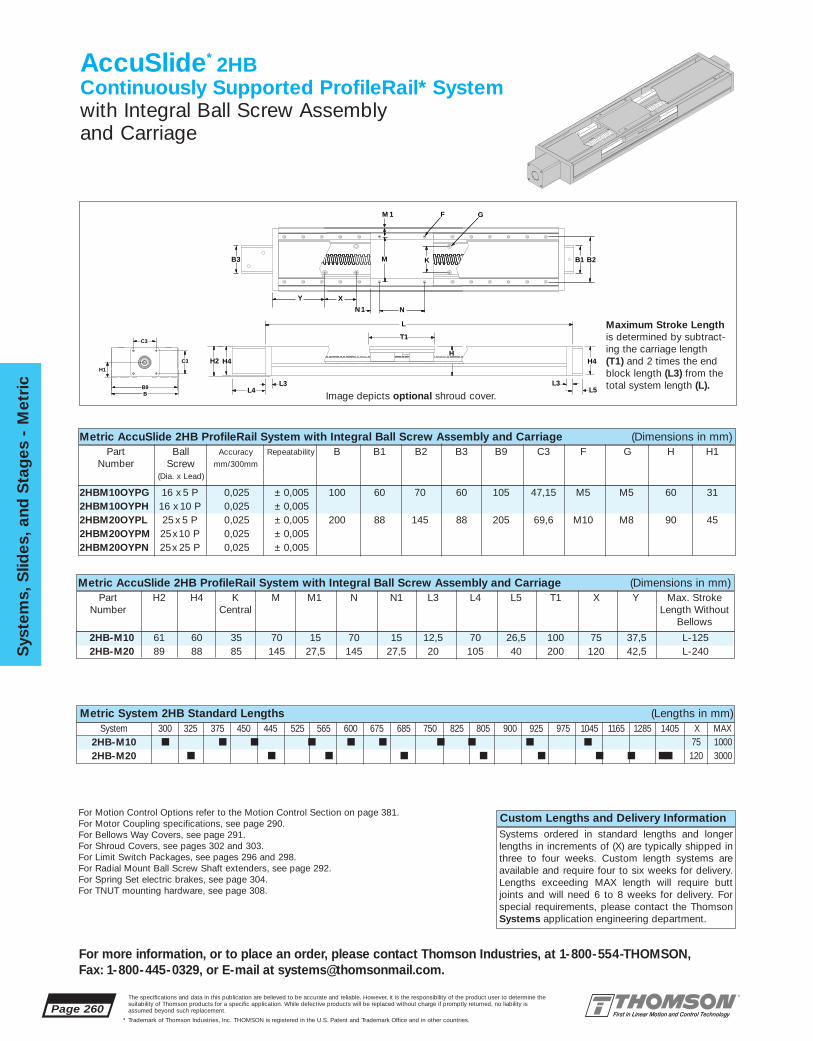
2HB-M10 ■ ■ ■ ■ ■ ■ ■ ■ ■ ■
2HB-M20 ■ ■ ■ ■ ■ ■ ■ ■ ■
Page 260
Sys
tem
s, S
lides
, and
Sta
ges
- M
etri
c
For more information, or to place an order, please contact Thomson Industries, at 1-800-554-THOMSON, Fax: 1-800-445-0329, or E-mail at [email protected].
The specifications and data in this publication are believed to be accurate and reliable. However, it is the responsibility of the product user to determine thesuitability of Thomson products for a specific application. While defective products will be replaced without charge if promptly returned, no liability isassumed beyond such replacement.
* Trademark of Thomson Industries, Inc. THOMSON is registered in the U.S. Patent and Trademark Office and in other countries.
75 1000■ 120 3000
2HB-M10 61 60 35 70 15 70 15 12,5 70 26,5 100 75 37,5 L-1252HB-M20 89 88 85 145 27,5 145 27,5 20 105 40 200 120 42,5 L-240
2HBM10OYPG 16 x 5 P 0,025 ± 0,005 100 60 70 60 105 47,15 M5 M5 60 312HBM10OYPH 16 x 10 P 0,025 ± 0,0052HBM20OYPL 25 x 5 P 0,025 ± 0,005 200 88 145 88 205 69,6 M10 M8 90 452HBM20OYPM 25x10 P 0,025 ± 0,0052HBM20OYPN 25x 25 P 0,025 ± 0,005
AccuSlide* 2HBContinuously Supported ProfileRail* Systemwith Integral Ball Screw Assembly and Carriage
Part H2 H4 K M M1 N N1 L3 L4 L5 T1 X Y Max. StrokeNumber Central Length Without
Bellows
L
L4
H4
L3
T1
HH2
L3
H4
L5
C3
B9
H1
B
C3
Metric AccuSlide 2HB ProfileRail System with Integral Ball Screw Assembly and Carriage (Dimensions in mm)Part Ball Accuracy Repeatability B B1 B2 B3 B9 C3 F G H H1
Number Screw mm/300mm
(Dia. x Lead)
Custom Lengths and Delivery InformationSystems ordered in standard lengths and longerlengths in increments of (X) are typically shipped inthree to four weeks. Custom length systems areavailable and require four to six weeks for delivery.Lengths exceeding MAX length will require buttjoints and will need 6 to 8 weeks for delivery. Forspecial requirements, please contact the ThomsonSystems application engineering department.
B3 KM B1 B2
Y
N
X
N 1
M 1 F G
Metric AccuSlide 2HB ProfileRail System with Integral Ball Screw Assembly and Carriage (Dimensions in mm)
Maximum Stroke Lengthis determined by subtract-ing the carriage length (T1) and 2 times the endblock length (L3) from thetotal system length (L).
Metric System 2HB Standard Lengths (Lengths in mm)System 300 325 375 450 445 525 565 600 675 685 750 825 805 900 925 975 1045 1165 1285 1405 X MAX
Image depicts optional shroud cover.
For Motion Control Options refer to the Motion Control Section on page 381.For Motor Coupling specifications, see page 290.For Bellows Way Covers, see page 291.For Shroud Covers, see pages 302 and 303.For Limit Switch Packages, see pages 296 and 298.For Radial Mount Ball Screw Shaft extenders, see page 292.For Spring Set electric brakes, see page 304.For TNUT mounting hardware, see page 308.

System
s, Slid
es, and S
tages - M
etric
Page 261
For more information, or to place an order, please contact Thomson Industries, at 1-800-554-THOMSON, Fax: 1-800-445-0329, or E-mail at [email protected].
The specifications and data in this publication are believed to be accurate and reliable. However, it is the responsibility of the product user to determine thesuitability of Thomson products for a specific application. While defective products will be replaced without charge if promptly returned, no liability isassumed beyond such replacement.
* Trademark of Thomson Industries, Inc. THOMSON is registered in the U.S. Patent and Trademark Office and in other countries.
Specifying a Thomson System:1. Determine the proper system for your load and liferequirements. 2. Select the part number. 3. Add the letter “L” followed by the overall length in illimeters, asa suffix to the part number (choosing a standard lengthwill reduce costs and speed delivery). 4.Place yourorder with your local authorized Thomson distributor.Part Numbering System
2HB-M20-OYP L L685System SystemDesignation LengthNominal Diameter Type of Ball Screw
Type of CarriageType of Support
2HB-M10 10 10,5 6 3 2,5 70 15 60 31 15 13 1002HB-M20 20 16,5 8,1 6 4 155 22,5 90 45 22,5 20 200
AccuSlide* 2HB Benefits:■ Used in continuously supported
applications that require high stiffness and rigidity.
■ Single part number is all that is required
■ Equipped with high load andmoment capacity AccuGlide*ProfileRail* System.
Metric AccuSlide 2HB ProfileRail System with Integral Ball Screw Assembly and Carriage (Dimensions in mm)Part Nominal D5 D6 D7 D8 B6 B7 H H1 H6 H9 T
Number Diameter
AccuSlide 2HB Components:■ 1 double ProfileRail System
Assembly.■ 1 carriage with 4 mounting holes■ 1 Integral Ball Screw Assembly
D6
D7D8
D5
B6
H1
T
H
H9
H6
B7
T-Slots
Load/Life GraphLines indicate limiting load for given shaft size
Lo
ad o
n m
ost
hea
vily
load
ed b
eari
ng
(N
)
10 100 1 000 10 000 100 000
Required Travel Life (km)
100
1 000
100 000
10 000
2HB-M10
2HB-M20
2HB-M15
Compressive Load
10000
1000
500
Co
mp
ress
ive
Load
on
Scr
ew (N
)
10 100
1000
2000
Mass on Carriage (kg)
Acceleration (m/s2)30 20 10
8
65
4
3
2
1
100
Maximum AcceptableTravel Rate✝
5000
1000
500
System Length (mm)✝80% of Critical Speed
400 1000 2000
Ro
tati
ona
l Sp
eed
(rev
/min
)
1003000
Maximum AllowableCompressive Load
10000
1000
500
Max
imum
Allo
wab
le C
om
pre
ssiv
e Lo
ad (N
)
1000
System Length (mm)
100
100 2000 3000
16 x 5 P, 16 x 10P, 16 x 16P
25 x 5 P, 25 x 10 P, 25 x 25 P
20 x 5 P, 20 x 10 P, 20 x 20 P
16 x 5 P
25 x 5 P
25 x 10 P
20 x 20 P20 x 5 P
25 x 25 P
16 x 10 P16 x 16 P
20 x 10 P
Image depicts optional shroud cover.
The AccuSlide has a pre-designed MaximumAcceptable Travel Rate. Calculate maximumrotational speed (rpm) by dividing your requiredmaximum linear speed (m/s) by the correspond-ing system ball screw lead (m/rev). Enter thechart with the required system length and yourmaximum rotational speed. Select the systemwith a maximum acceptable travel rate curveabove the plotted line.
Compressive load on the ball screw is a keyfactor in selecting the proper System. Using maximum load and acceleration requirements, plot compressive load on the left side of thechart.Using System length and compressiveload. plot the maximum allowable compres-sive force on the right chart. Select theSystem with a rated maximum compressiveforce above your plotted point.
If you have questions concerning your systemrequirements, contact the Thomson Systemsapplication engineering department.
Note: Ball screw should never exceed recommended critical speed.
Appropriate mounting holes can be added for mounting the base of one systemto the carriage of another for x–y configurations.

2RB-M12 ■ ■ ■ ■ ■ ■ ■ ■ ■ ■ ■ ■ ■
2RB-M16 ■ ■ ■ ■ ■ ■ ■ ■ ■ ■
■ ■ ■ ■ 75 2100■ ■ ■ 100 3000
Page 262
Sys
tem
s, S
lides
, and
Sta
ges
- M
etri
c
For more information, or to place an order, please contact Thomson Industries, at 1-800-554-THOMSON, Fax: 1-800-445-0329, or E-mail at [email protected].
The specifications and data in this publication are believed to be accurate and reliable. However, it is the responsibility of the product user to determine thesuitability of Thomson products for a specific application. While defective products will be replaced without charge if promptly returned, no liability isassumed beyond such replacement.
* Trademark of Thomson Industries, Inc. THOMSON is registered in the U.S. Patent and Trademark Office and in other countries.
2RB-M12-ODM 75 60 110 9,5 70 26,5 130 75 75 L-1492RB-M16-ODM 79 60 135 12,5 75 31,5 160 100 100 L-1852RB-M20-ODM L-(000)
SuperSlide* 2RBContinuously Supported Systemwith Integral Ball Screw Assembly and T-Slot Carriage
SuperSlide 2RB System with Integral Ball Screw Assembly and T-Slot Carriage (Dimensions in mm)Part H2 H4 K L3 L4 L5 T1 Max.
Number StrokeX Y Length
L
H
L4L5
H2 H4
L3L3
T1
H4
L3B2
B
C3
C3
H1H2
SuperSlide 2RB System with Integral Ball Screw Assembly and T-Slot Carriage (Dimensions in mm)Part Nominal Ball Accuracy Repeatability B B2 B3 C3 G H1
Number Dia. Screw mm/300 mm(Dia. x Lead)
New... Super SmartBall Bushing* Bearing...Now Available For All Sizes
Custom Lengths and Delivery InformationSystems ordered in standard lengths and longerlengths in increments of (X) are typically shipped intwo to three weeks. Custom length systems areavailable and require three to four weeks for deliv-ery. Lengths exceeding MAX length will require buttjoints and will need 4 to 6 weeks for delivery. Forspecial requirements, please contact the ThomsonSystems application engineering department.
GY X
KB3B3
Base Mounting Holes
Maximum Stroke Lengthis determined by subtracting the carriage length (T1) and 2x end block length (L3) fromthe total system length.
System 2RB Standard Lengths (Lengths in mm)System 300 375 400 450 500 525 600 675 700 750 800 825 900 975 1000 1050 1100 11251200 1275 1300 1350 1400 1425 1500 X MAX
2RB-M12-ODM-G 12 16x 5 P 0,025 ± 0,005 130 75 60 47,15 M4 402RB-M12-ODM-H 12 16x 10 P 0,025 ± 0,0052RB-M16-ODM-I 16 20 x 5 P 0,025 ± 0,005 160 95 60 47,15 M5 482RB-M16-ODM-J 16 20 x 10 P 0,025 ± 0,0052RB-M16-ODM-K 16 20 x 20 P 0,025 ± 0,0052RB-M20-ODM 20
For Motion Control Options refer to the Motion Control Section on page 381.For Motor Coupling specifications, see page 290.For Bellows Way Covers, see page 291.For Limit Switch Packages, see pages 300-301.For Radial Mount Ball Screw Shaft Extenders, see page 292.For Spring Set electric brakes, see page 304.For TNUT mounting hardware, see page 308.

System
s, Slid
es, and S
tages - M
etric
Page 263
For more information, or to place an order, please contact Thomson Industries, at 1-800-554-THOMSON, Fax: 1-800-445-0329, or E-mail at [email protected].
The specifications and data in this publication are believed to be accurate and reliable. However, it is the responsibility of the product user to determine thesuitability of Thomson products for a specific application. While defective products will be replaced without charge if promptly returned, no liability isassumed beyond such replacement.
* Trademark of Thomson Industries, Inc. THOMSON is registered in the U.S. Patent and Trademark Office and in other countries.
2RB-M12-ODM 2,75 2 7,5 13 4 3 65 40 35 7 14 1302RB-M16-ODM 3,5 2,5 8,1 16,5 6,8 3 80 48 41,5 10 20 1602RB-M20-ODM
2RB-M12-ODM 12 75 27,5 65 32,5 8,0 4,2 2,75 2 8,0 4,22RB-M16-ODM 16 100 30 80 40 10,5 6 3,5 2,5 10,5 62RB-M20-ODM 20
SuperSlide* 2RB Benefits:■ Used in continuously supported
applications when stiffness andrigidity is required.
■ Single part number is all that is required
■ T-Slot in carriage provides quickand easy mounting and removal of the workpiece.
Specifying a Thomson System:1. Determine the proper system for your load and liferequirements. 2. Select the part number. 3. Add the letter “L” followed by the overall length in millimeters, asa suffix to the part number (choosing a standard lengthwill reduce costs and speed delivery). 4.Place your orderwith your local authorized Thomson distributor.Part Numbering System
2RB-M16-ODM-I L600System SystemDesignation LengthNominal Diameter Type of Ball Screw
Type of Carriage
Type of Support
Load/Life GraphLines indicate limiting load for given shaft size
Lo
ad o
n m
ost
hea
vily
load
ed b
eari
ng
(N
)
1010
100
100
1 000
1 000
10 000
10 000
100 000
Required Travel Life (km)
2RB-M16
2RB-M302RB-M25
2RB-M20
2RB-M12
SuperSlide 2RB System with Integral Ball Screw Assembly and T-Slot Carriage (Dimensions in mm)
SuperSlide 2RB System with Integral Ball Screw Assembly and T-Slot Carriage (Dimensions in mm)
Part Nominal B4 B5 B6 B7 D1 D2 D3 D4 D5 D6Number Diameter
Part D7 D8 E1 E2 E3 E4 H H1 H6 H7 H9 TNumber
SuperSlide 2RB Components:■ 1 double LinearRace* Rail Assembly
with T-Slots for mounting ease.■ 1 T-Slot integrated carriage with
4 open type Super Smart BallBushing* bearings.
■ 1 Integral Ball Screw Assembly
C1
C2
B6
H9
T
H6
H7
B7
T7T7
T8
T8
T8
T8
T4T4
B5 B4T
H
H1
T7 T-Slots
Carriage X-Section
E1
E2E3
E4 D6
D5D7
D8
D2
D3D4
D1
T4 T-Slots
T8 T-Slots
Compressive Load
10000
1000
500
Co
mp
ress
ive
Load
on
Scr
ew (N
)
10 100
1000
2000
Mass on Carriage (kg)
Acceleration (m/s2)30 20 10
8
65
4
3
2
1
100
Maximum AllowableCompressive Load
10000
1000
500
Max
imum
Allo
wab
le C
om
pre
ssiv
e Lo
ad (N
)
1000
System Length (mm)
100
100 2000 3000
Maximum AcceptableTravel Rate✝
5000
1000
500
System Length (mm)✝80% of Critical Speed
400 1000 2000
Ro
tati
ona
l Sp
eed
(rev
/min
)
1003000
16 x 5 P, 16 x 10P, 16 x 16P
25 x 5 P, 25 x 10 P, 25 x 25 P
20 x 5 P, 20 x 10 P, 20 x 20 P
16 x 5 P
25 x 5 P
25 x 10 P
20 x 20 P20 x 5 P
25 x 25 P
16 x 10 P16 x 16 P
20 x 10 P
The SuperSlide has a pre-designed MaximumAcceptable Travel Rate. Calculate maximumrotational speed (rpm) by dividing your requiredmaximum linear speed (m/s) by the correspond-ing system ball screw lead (m/rev). Enter thechart with the required system length and yourmaximum rotational speed. Select the systemwith a maximum acceptable travel rate curveabove the plotted line.
Compressive load on the ball screw is a keyfactor in selecting the proper System. Using maximum load and acceleration requirements, plot compressive load on the left side of thechart.Using System length and compressiveload. plot the maximum allowable compres-sive force on the right chart. Select theSystem with a rated maximum compressiveforce above your plotted point.
If you have questions concerning your systemrequirements, contact the Thomson Systemsapplication engineering department.
Note: Ball screw should never exceed recommended critical speed.
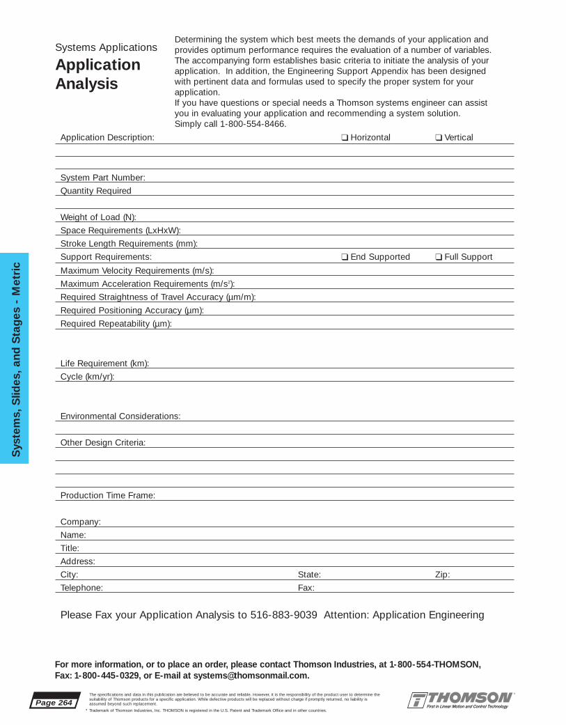
Page 264
Sys
tem
s, S
lides
, and
Sta
ges
- M
etri
c
For more information, or to place an order, please contact Thomson Industries, at 1-800-554-THOMSON, Fax: 1-800-445-0329, or E-mail at [email protected].
The specifications and data in this publication are believed to be accurate and reliable. However, it is the responsibility of the product user to determine thesuitability of Thomson products for a specific application. While defective products will be replaced without charge if promptly returned, no liability isassumed beyond such replacement.
* Trademark of Thomson Industries, Inc. THOMSON is registered in the U.S. Patent and Trademark Office and in other countries.
Systems Applications
ApplicationAnalysis
Determining the system which best meets the demands of your application and provides optimum performance requires the evaluation of a number of variables. The accompanying form establishes basic criteria to initiate the analysis of your application. In addition, the Engineering Support Appendix has been designed with pertinent data and formulas used to specify the proper system for your application.If you have questions or special needs a Thomson systems engineer can assist you in evaluating your application and recommending a system solution. Simply call 1-800-554-8466.
Application Description: ❑ Horizontal ❑ Vertical
System Part Number:
Quantity Required
Weight of Load (N):
Space Requirements (LxHxW):
Stroke Length Requirements (mm):
Support Requirements: ❑ End Supported ❑ Full Support
Maximum Velocity Requirements (m/s):
Maximum Acceleration Requirements (m/s2):
Required Straightness of Travel Accuracy (µm/m):
Required Positioning Accuracy (µm):
Required Repeatability (µm):
Life Requirement (km):
Cycle (km/yr):
Environmental Considerations:
Other Design Criteria:
Production Time Frame:
Company:
Name:
Title:
Address:
City: State: Zip:
Telephone: Fax:
Please Fax your Application Analysis to 516-883-9039 Attention: Application Engineering

The specifications and data in this publication are believed to be accurate and reliable. However, it is the responsibility of the product user to determine thesuitability of Thomson products for a specific application. While defective products will be replaced without charge if promptly returned, no liability isassumed beyond such replacement.
* Trademark of Thomson Industries, Inc. THOMSON is registered in the U.S. Patent and Trademark Office and in other countries.
System
s, Slid
es, and S
tages - M
etric
Page 265
For more information, or to place an order, please contact Thomson Industries, at 1-800-554-THOMSON, Fax: 1-800-445-0329, or E-mail at [email protected].
SuperSlide* Belt Actuated Systemsoffer:• An end supported and continuously
supported version complete with prealigned LinearRace* ways and an integral belt drive assembly. End Supported Systems are used when spanning or bridging a gap. While Continuously Supported Systems are used when rigidity is required.
• Available with uniquely designed carriages and LinearRace assemblies with integrated T-slots for easy assembly and mounting.
• High speed and acceleration with positioningaccuracy better than 0,2 mm/ 300 mm andrepeatability within 0,10 mm. Improvement insystem performance is realized immediately.
• Available with integrated Super Smart BallBushing* bearings which provide up to six times the load capacity or 216 times the travel life of conventional linear bearing based systems.
• Anodized coating, double acting integralwipers and bellows for protection in corrosive environments. A uniquely designedlubrication system option is available for allsystems.
• A precision gearhead for matching the inertiabetween the belt drive system payload andthe servo motor. The True Planetary* gearhead design provides torque capacity upto 28 N-m at speeds as high as 4000 rpm.
• A single part number system. All that isrequired to order is to specify the system nominal size and length.
• Easy adaptation to the Thomson AXI-PAK*Motion Control system. Once the SuperslideBelt Drive system has been selected simplyspecify a standard Thomson Motion Controlpackage that meets your complete motioncontrol needs.(See the Motion Control section on page 381)
SuperSlideBelt Actuated Systems

60 Case LinearRace ways
External Accessory T-Slotsin Base
T-Slots in Carriage
System End Support
System 2NE Cross Section
Super Smart Ball Bushing bearing
Belt Drive Assembly
SuperSlide 2NE End Supported Belt Actuated System Features:
• End Supported System • Integral Precision Gearhead
• Precision Steel Reinforced Timing Belt • Double Acting Seals
• T-Slots in Carriage • Optional Lubrication System
• T-Slots in Base Mounting System • Speeds in excess of 3 m/s
• Positioning Accuracy less than 0,2 mm/300 mm • Single Part Number System
• Long Travel Life • Standard NEMA Motor Mounting
• Super Smart Ball Bushing bearings • Protective Bellows Option
SuperSlide* 2NE Belt Actuated System
T-Slots in Carriage
Carriage
NemaTRUE*TRUE Planetary* gearhead
Steel CableReinforced
Precision Timing Belt 60 Case*
LinearRace*ways
T-Slotted Carriage
Super Smart Ball Bushing* bearing
Idler Pulley Assembly
T-Slotted End Supports
Drive PulleyAssembly
Page 266The specifications and data in this publication are believed to be accurate and reliable. However, it is the responsibility of the product user to determine thesuitability of Thomson products for a specific application. While defective products will be replaced without charge if promptly returned, no liability isassumed beyond such replacement.
* Trademark of Thomson Industries, Inc. THOMSON is registered in the U.S. Patent and Trademark Office and in other countries.
Sys
tem
s, S
lides
, and
Sta
ges
- M
etri
c
For more information, or to place an order, please contact Thomson Industries, at 1-800-554-THOMSON, Fax: 1-800-445-0329, or E-mail at [email protected].

The specifications and data in this publication are believed to be accurate and reliable. However, it is the responsibility of the product user to determine thesuitability of Thomson products for a specific application. While defective products will be replaced without charge if promptly returned, no liability isassumed beyond such replacement.
* Trademark of Thomson Industries, Inc. THOMSON is registered in the U.S. Patent and Trademark Office and in other countries.
System
s, Slid
es, and S
tages - M
etric
Page 267
For more information, or to place an order, please contact Thomson Industries, at 1-800-554-THOMSON, Fax: 1-800-445-0329, or E-mail at [email protected].
60 Case LinearRace ways
External Accessory T-Slotsin Base
T-Slots in Carriage
System Support Base
System 2RECross Section
Open Type Super SmartBall Bushing bearing
Belt Drive Assembly
Internal Accessory T-Slotsin Base
SuperSlide* 2RE Belt Actuated System
SuperSlide 2RE Belt Actuated System Features:
• Continuously Supported System • Load Capacities up to 5446 N at 250 Km of travel life.
• Precision Steel Reinforced Timing Belt • Double Acting Seals
• T-Slots in Carriage • Optional Lubrication System
• T-Slots in Base Mounting System • Speeds in excess of 3 m/s
• Positioning Accuracy less than 0,2 mm/300 mm • Integral Precision Gearhead
• Long Travel Life • Standard NEMA Motor Mounting
• Super Smart Ball Bushing bearing • Protective Bellows Option
NemaTRUE*TRUE Planetary* gearhead
Steel Cable ReinforcedPrecision Belt Timing
60 Case* LinearRace* ways
T-Slotted Carriage
Super Smart Ball Bushing* bearing
Idler Pulley Assembly
Drive Pulley Assembly
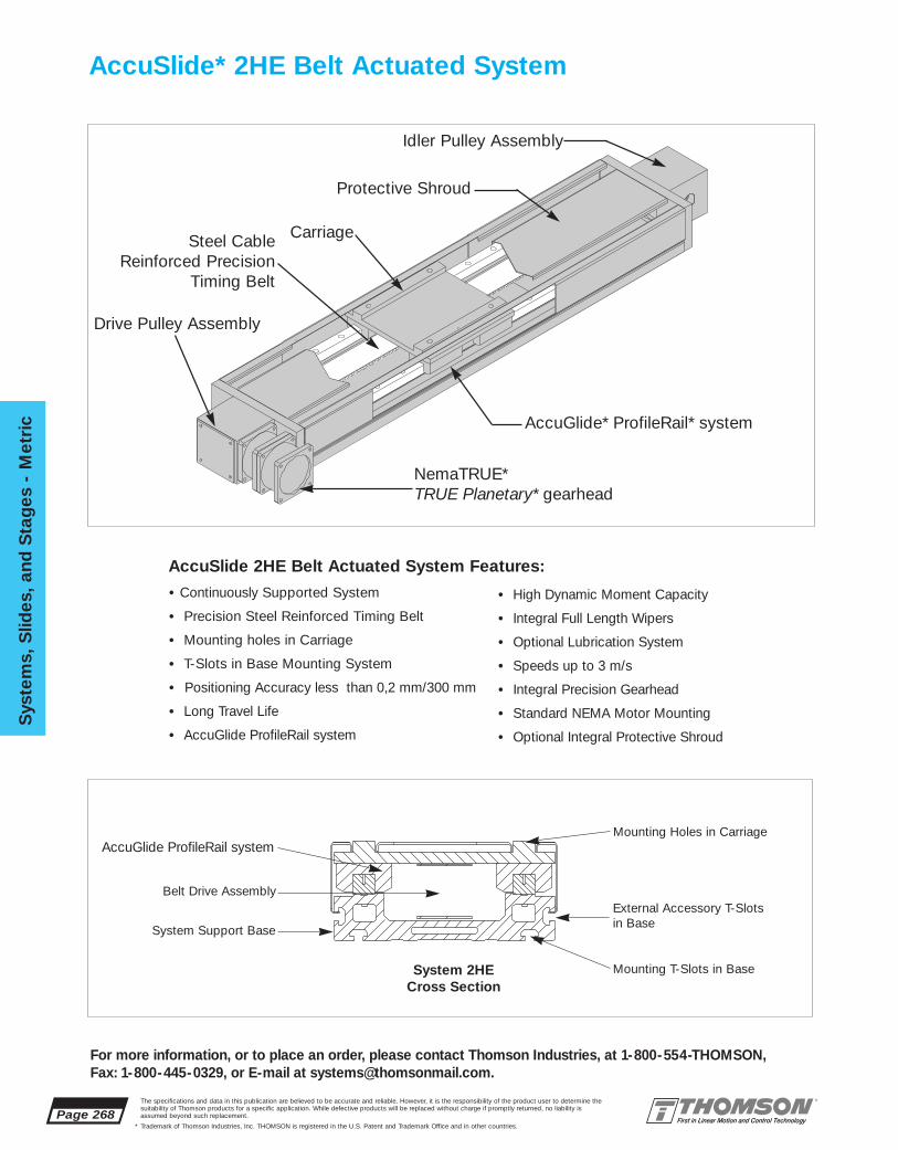
Page 268The specifications and data in this publication are believed to be accurate and reliable. However, it is the responsibility of the product user to determine thesuitability of Thomson products for a specific application. While defective products will be replaced without charge if promptly returned, no liability isassumed beyond such replacement.
* Trademark of Thomson Industries, Inc. THOMSON is registered in the U.S. Patent and Trademark Office and in other countries.
Sys
tem
s, S
lides
, and
Sta
ges
- M
etri
c
For more information, or to place an order, please contact Thomson Industries, at 1-800-554-THOMSON, Fax: 1-800-445-0329, or E-mail at [email protected].
AccuSlide* 2HE Belt Actuated System
External Accessory T-Slotsin Base
Mounting Holes in Carriage
System Support Base
System 2HECross Section
AccuGlide ProfileRail system
Belt Drive Assembly
Mounting T-Slots in Base
• Continuously Supported System
• Precision Steel Reinforced Timing Belt
• Mounting holes in Carriage
• T-Slots in Base Mounting System
• Positioning Accuracy less than 0,2 mm/300 mm
• Long Travel Life
• AccuGlide ProfileRail system
• High Dynamic Moment Capacity
• Integral Full Length Wipers
• Optional Lubrication System
• Speeds up to 3 m/s
• Integral Precision Gearhead
• Standard NEMA Motor Mounting
• Optional Integral Protective Shroud
NemaTRUE*TRUE Planetary* gearhead
Steel CableReinforced Precision
Timing Belt
Protective Shroud
Carriage
AccuGlide* ProfileRail* system
Idler Pulley Assembly
Drive Pulley Assembly
AccuSlide 2HE Belt Actuated System Features:
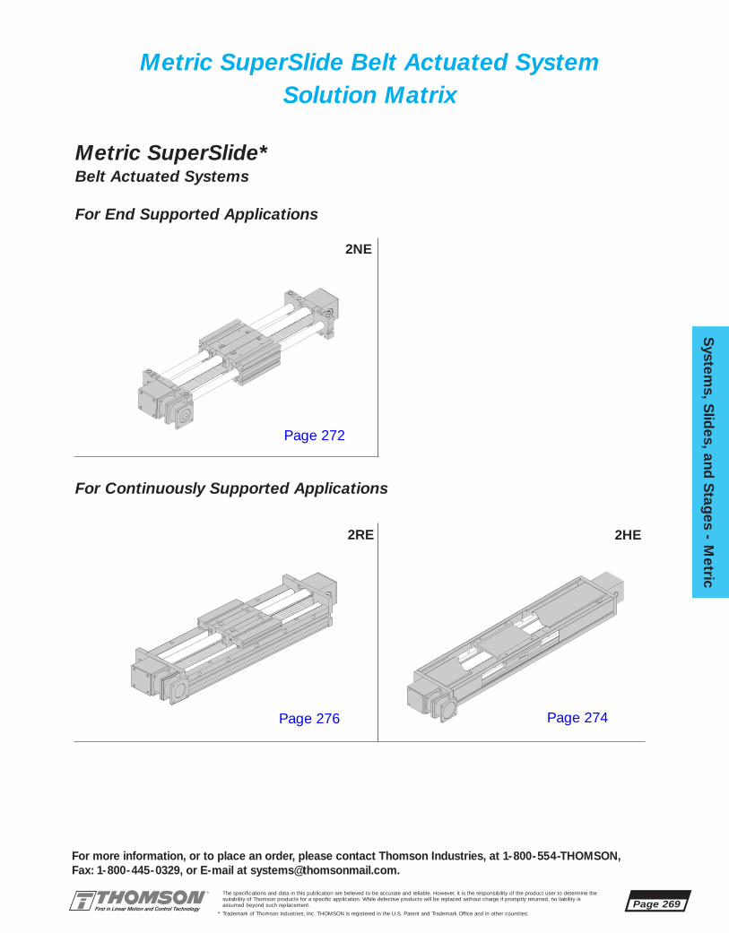
The specifications and data in this publication are believed to be accurate and reliable. However, it is the responsibility of the product user to determine thesuitability of Thomson products for a specific application. While defective products will be replaced without charge if promptly returned, no liability isassumed beyond such replacement.
* Trademark of Thomson Industries, Inc. THOMSON is registered in the U.S. Patent and Trademark Office and in other countries.
System
s, Slid
es, and S
tages - M
etric
Page 269
For more information, or to place an order, please contact Thomson Industries, at 1-800-554-THOMSON, Fax: 1-800-445-0329, or E-mail at [email protected].
Metric SuperSlide*Belt Actuated Systems
For End Supported Applications
Metric SuperSlide Belt Actuated SystemSolution Matrix
For Continuously Supported Applications
2NE
2RE 2HE
Page 272
Page 276 Page 274
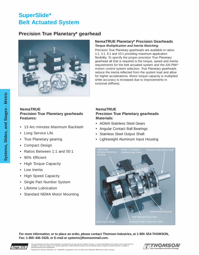
Page 270The specifications and data in this publication are believed to be accurate and reliable. However, it is the responsibility of the product user to determine thesuitability of Thomson products for a specific application. While defective products will be replaced without charge if promptly returned, no liability isassumed beyond such replacement.
* Trademark of Thomson Industries, Inc. THOMSON is registered in the U.S. Patent and Trademark Office and in other countries.
Sys
tem
s, S
lides
, and
Sta
ges
- M
etri
c
For more information, or to place an order, please contact Thomson Industries, at 1-800-554-THOMSON, Fax: 1-800-445-0329, or E-mail at [email protected].
SuperSlide*Belt Actuated System
NemaTRUE Precision True Planetary gearheadsFeatures:
• 13 Arc-minutes Maximum Backlash
• Long Service Life
• True Planetary gearing
• Compact Design
• Ratios Between 1:1 and 50:1
• 90% Efficient
• High Torque Capacity
• Low Inertia
• High Speed Capacity
• Single Part Number System
• Lifetime Lubrication
• Standard NEMA Motor Mounting
Stainless Steel Output Shaft
NemaTRUE Precision True Planetary gearheadsMaterials:• AGMA Stainless Steel Gears• Angular Contact Ball Bearings• Stainless Steel Output Shaft• Lightweight Aluminum Input Housing
NemaTRUE Planetary* Precision GearheadsTorque Multiplication and Inertia Matching. Precision True Planetary gearheads are available in ratios1:1, 3.1, 5:1 and 10:1 providing maximum application flexibility. To specify the proper precision True Planetarygearhead all that is required is the torque, speed and inertiarequirements for the belt actuated system and the AXI-PAK*motion control system selection. True Planetary gearheadsreduce the inertia reflected from the system load and allowfor higher accelerations. Motor torque capacity is multipliedwhile accuracy is increased due to improvements in torsional stiffness.
Precision True Planetary* gearhead
Balanced Collar Clamp and Pinion
Heat Resistant Input Seal
Needle Roller Bearings
LightweightAnodized AluminumHousing
AGMA 12 HardenedStainless Steel Gears
Motor Input Flange

The specifications and data in this publication are believed to be accurate and reliable. However, it is the responsibility of the product user to determine thesuitability of Thomson products for a specific application. While defective products will be replaced without charge if promptly returned, no liability isassumed beyond such replacement.
* Trademark of Thomson Industries, Inc. THOMSON is registered in the U.S. Patent and Trademark Office and in other countries.
System
s, Slid
es, and S
tages - M
etric
Page 271
For more information, or to place an order, please contact Thomson Industries, at 1-800-554-THOMSON, Fax: 1-800-445-0329, or E-mail at [email protected].
SuperSlide* Belt Driven SystemSystem Selection
Many variables influence the selection of a Linear Motion System. The best solutiondemands a thorough evaluation of the application, only then can design criteria be established. Issues such as envelope limitations, system load capacity, actuator loadcapacity, speed and acceleration, drive requirements, accuracy and repeatability, andoperating environment are looked at from a broad perspective to determine the type ofsystem, type of actuator, and whether the system need be built of special materials.
Typically, a belt actuated linear motion system is ideal for moderate precision, high load,and high-speed applications. When compared to a Ball Screw Actuated Linear MotionSystem, the Belt Actuated System can attain higher linear speeds in longer stroke applications. A degree of positioning accuracy, however, is sacrificed, as the belt is notcapable of meeting the accuracy of that of the ball screw. Since the belt actuated is actuated through a True Planetary* gearhead, the torque, speed, and system inertia canbe matched by varying the gear ratio. If an application requires rigidity, then a fullysupported system should be specified in lieu of an end supported type system. Forextremely heavy-duty applications, the AccuSlide* (2HE series) system, with its use ofProfileRail* type Linear Guides is adept at handling normal axis, overhung, or cantileverloads of increased magnitude. In environments that are corrosive or high temperaturespecial materials may be required and are available. Contact Application Engineering fordetails on special materials.
In order to determine the Belt Actuated SuperSlide System that meets the needs of yourapplication, it is first necessary to evaluate the following detail design criteria:
• System support requirements• System stroke length• Maximum allowable shaft deflection• Required travel life• Force on the most heavily loaded bearing• Load correction factor• Load/Life requirements-linear bearings• Motion (move) profile (velocity, acceleration)• Maximum belt tooth shear strength• Gear motor rotational speed (gear reduction)• Torque considerations• Size motor using torque/speed curves
A detailed explanation of the procedure for selecting a Belt Actuated Linear MotionSystem is given on page 342 in the Engineering Support Section.

2NE-M16 ■ ■ ■ ■ ■ ■ ■ ■ ■ ■ ■ ■ ■
2NE-M20 ■ ■ ■ ■ ■ ■ ■ ■ ■ ■
Page 272The specifications and data in this publication are believed to be accurate and reliable. However, it is the responsibility of the product user to determine thesuitability of Thomson products for a specific application. While defective products will be replaced without charge if promptly returned, no liability isassumed beyond such replacement.
* Trademark of Thomson Industries, Inc. THOMSON is registered in the U.S. Patent and Trademark Office and in other countries.
Sys
tem
s, S
lides
, and
Sta
ges
- M
etri
c
For more information, or to place an order, please contact Thomson Industries, at 1-800-554-THOMSON, Fax: 1-800-445-0329, or E-mail at [email protected].
2NE-M16-OLL-A 1:1 NEMA23 NT-23-12NE-M16-OLL-B 3:1 NEMA23 NT-23-32NE-M16-OLL-C 5:1 NEMA23 NT-23-52NE-M16-OLL-D 10:1 NEMA23 NT-23-102NE-M20-OLL-A 1:1 NEMA23 NT-23-12NE-M20-OLL-B 3:1 NEMA23 NT-23-32NE-M20-OLL-C 5:1 NEMA23 NT-23-52NE-M20-OLL-D 10:1 NEMA23 NT-23-10
2NE-M16-OLL-2NE-M20-OLL- 20 61,5 61,5 71,6 24,1 M6 11,25 160 23
SuperSlide* 2NEEnd Supported Systemwith Integral Belt Drive Assembly and T-Slot Carriage
L
L4
H4
L3
C3
T1
C3 H2 H
L5L3
H4
B2B
H1
L8Maximum Stroke Lengthis determined by subtracting the carriage length (T1) and end block length (L3) from thetotal system length (L).
SuperSlide 2NE System with Integral Belt Actuated Assembly and T-Slot Carriage (Dimensions in mm)Part Nominal B B1 B2 B3 B8 C3 H H1 H2 H4 Max.
Number Dia. StrokeLength
SuperSlide 2NE System with Integral Belt Actuated Assembly and T-Slot Carriage (Dimensions in mm)Part L3 L4 L5 L7 L8 N N1 T1 NEMA
Number Bolt Hole Size
New... Super SmartBall Bushing* Bearing...Now Available For All Sizes
Custom Lengths and Delivery InformationSystems ordered in standard lengths and longerlengths in increments of (X) are typically shipped in twoto three weeks. Custom length systems are availableand require three to four weeks for delivery. For specialrequirements, please contact the Thomson Systemsapplication engineering department.
B8
B3
L 7
B3
N/N1
B 1
System 2NE Standard Lengths (Lengths in mm)System 300 375 400 450 500 525 600 675 700 750 800 825 900 975 1000 1050 1100 11251200 1275 1300 1350 1400 1425 1500 X MAX
Metric SuperSlide 2NESystem Gear Motor Gearbox
Part Number Ratio Frame Size Part Number
2NE-M16-OLL- 162NE-M20-OLL- 20 160 75 110 65 7,5 47,15 66 34 65 60 L-200
For Motion Control Options refer to the Motion Control Section on page 381.For Bellows Way Covers, see page 291.For Spring Set electric brakes, see page 304.For TNUT mounting hardware, see page 308.
■ ■ ■ ■75 1500■ ■ ■ 100 2000

The specifications and data in this publication are believed to be accurate and reliable. However, it is the responsibility of the product user to determine thesuitability of Thomson products for a specific application. While defective products will be replaced without charge if promptly returned, no liability isassumed beyond such replacement.
* Trademark of Thomson Industries, Inc. THOMSON is registered in the U.S. Patent and Trademark Office and in other countries.
System
s, Slid
es, and S
tages - M
etric
Page 273
For more information, or to place an order, please contact Thomson Industries, at 1-800-554-THOMSON, Fax: 1-800-445-0329, or E-mail at [email protected].
2NE-M16-OLL-2NE-M20-OLL- 8,1 16,5 6,8 3,0 8,1 16,5 6,8 4,5 66 63,5 19 32 15 160
2NE-M16-OLL- 162NE-M20-OLL- 20 75 120 20 120 20 120 6 10,5 4 3
SuperSlide* 2NE Benefits:■ Used in end supported applica-
tions when spanning or bridginga gap is required.
■ High speed and acceleration.■ T-Slots in carriage provides quick
and easy mounting and removal of the workpiece.
Specifying a Thomson System:1. Determine the proper system for your load and liferequirements. 2. Select the part number. 3. Add the letter “L” followed by the overall length in millimeters, asa suffix to the part number (choosing a standard lengthwill reduce costs and speed delivery). 4.Place yourorder with your local authorized Thomson distributor.Part Numbering System
2NE-M20-OLL-A-L600System SystemDesignation LengthNominal Diameter Type of Gearbox
Type of CarriageType of Support
SuperSlide 2NE System with Integral Belt Actuated Assembly and T-Slot Carriage (Dimensions in mm)
SuperSlide 2NE System with Integral Belt Actuated Assembly and T-Slot Carriage (Dimensions in mm)
Part Nominal B1 B4 B5 B6 B7 B9 D1 D2 D3 D4Number Diameter
Part E1 E2 E3 E4 E5 E6 E7 E8 H H3 H5 H6 H7 TNumber
SuperSlide 2NE Components:■ 2 LinearRace* End Support blocks
with T-Slots for mounting ease.■ 1 T-Slot integrated carriage with
4 Super Smart Ball Bushing* bearings.■ 1 Integral steel cable reinforced Belt
Assembly.■ 1 Integral NemaTRUE* Precision
Planetary Gearhead
B6
T6
T6
B5
T4
H3
B4T
HH6
H7
T6
T5
T6
T4
B7
T5
T6
T4T4
N/N1
H5T6
B1
B9
E6
E5E8
E7
D1
D3D4
D2
E1
E2E3
E4
End Block
(T4) T-slots
(T5) T-slots
(T6) T-slots
Carriage X-Section
Load/Life GraphLines indicate limiting load for given shaft size
Lo
ad o
n m
ost
hea
vily
load
ed b
eari
ng
(N
)
1010
100
100
1 000
1 000
10 000
10 000
100 000
Required Travel Life (km)
2NE-M16
2NE-M302NE-M40
2NE-M25
2NE-M20
2NE-M12
100 000
50 000
20 000
10 000
5 000
2 000
1 000
500
200
1000 1 2
System Length (m)
Load
on
Sys
tem
(N)
Maximum Recommended Load on System
2NE-M20
2NE-M16

2HE-M10 ■ ■ ■ ■ ■ ■ ■ ■ ■
2HE-M20 ■ ■ ■ ■ ■ ■
■ 75 1000■ ■ ■ ■120 3000
Page 274The specifications and data in this publication are believed to be accurate and reliable. However, it is the responsibility of the product user to determine thesuitability of Thomson products for a specific application. While defective products will be replaced without charge if promptly returned, no liability isassumed beyond such replacement.
* Trademark of Thomson Industries, Inc. THOMSON is registered in the U.S. Patent and Trademark Office and in other countries.
Sys
tem
s, S
lides
, and
Sta
ges
- M
etri
c
For more information, or to place an order, please contact Thomson Industries, at 1-800-554-THOMSON, Fax: 1-800-445-0329, or E-mail at [email protected].
2HE-M10-OZP 10 35 12,5 61,5 61,5 71,6 54,1 70 15 70 15 100 75 37,52HE-M20-OZP 20 85 20 101,5 101,5 95 42,5 145 27,5 145 27,5 200 120 42,5
2HE-M10-OZP 10 100 70 65 6,6 105 47,15 M5 M5 60 31 61 602HE-M20-OZP 20 200 145 95 10 205 69,6 M10 M8 90 45 89 88
AccuSlide* 2HEContinuously Supported ProfileRail* Systemwith Integral Belt Drive Assembly and Carriage
Metric System 2HE Standard Lengths (Lengths in mm)System 300 325 375 450 445 525 565 600 675 685 750 825 805 900 925
L
L4
H4
L3
T1
C3
C3H1
H2
L3L5
H4H
B9B
L8
Metric AccuSlide 2HE ProfileRail System with Integral Belt Actuated Assembly and Carriage (Dimensions in mm)Part Nominal B B2 B3 B8 B9 C3 F G H H1 H2 H4
Number Size
Custom Lengths and Delivery InformationSystems ordered in standard lengths and longerlengths in increments of (X) are typically shipped inthree to four weeks. Custom length systems areavailable and require four to six weeks for delivery.Lengths exceeding MAX length will require buttjoints and will need 6 to 8 weeks for delivery. Forspecial requirements, please contact the ThomsonSystems application engineering department.
KM B3 B2 B
Y
N
X
N 1
M 1
B3
B8
L7
F G
Metric AccuSlide 2HE ProfileRail System with Integral Belt Actuated Assembly and Carriage (Dimensions in mm)Part Nominal K L3 L4 L5 L7 L8 M M1 N N1 T1 X Y
Number Size Central
Maximum Stroke Lengthis determined by subtracting the carriage length (T1) and 2X end block length (L3)from the total system length (L).
975 1045 1165 1285 1405 X MAX
Image depicts optional shroud cover
For Motion Control Options refer to the Motion Control Section on page 381.For Bellows Way Covers, see page 291.For Shroud Covers, see pages 302 and 303.For Limit Switch Packages, see pages 297 and 299.For Spring Set electric brakes, see page 304.For TNUT mounting hardware, see page 308.
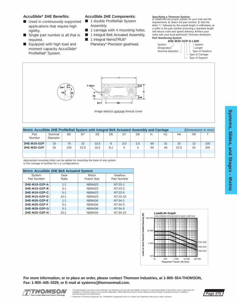
The specifications and data in this publication are believed to be accurate and reliable. However, it is the responsibility of the product user to determine thesuitability of Thomson products for a specific application. While defective products will be replaced without charge if promptly returned, no liability isassumed beyond such replacement.
* Trademark of Thomson Industries, Inc. THOMSON is registered in the U.S. Patent and Trademark Office and in other countries.
System
s, Slid
es, and S
tages - M
etric
Page 275
For more information, or to place an order, please contact Thomson Industries, at 1-800-554-THOMSON, Fax: 1-800-445-0329, or E-mail at [email protected].
2HE-M10-OZP-A 1:1 NEMA23 NT-23-12HE-M10-OZP-B 3:1 NEMA23 NT-23-32HE-M10-OZP-C 5:1 NEMA23 NT-23-52HE-M10-OZP-D 10:1 NEMA23 NT-23-102HE-M20-OZP-E 1:1 NEMA34 NT-34-12HE-M20-OZP-F 3:1 NEMA34 NT-34-32HE-M20-OZP-G 5:1 NEMA34 NT-34-52HE-M20-OZP-H 10:1 NEMA34 NT-34-10
2HE-M10-OZP 10 70 15 10,5 6 3,0 2,5 60 31 15 13 1002HE-M20-OZP 20 155 22,5 16,5 8,1 6 4 90 45 22,5 20 200
AccuSlide* 2HE Benefits:■ Used in continuously supported
applications that require high rigidity.
■ Single part number is all that is required.
■ Equipped with high load andmoment capacity AccuGlide*ProfileRail* System.
Specifying a Thomson System:1. Determine the proper system for your load and liferequirements. 2. Select the part number. 3. Add the letter “L” followed by the overall length in millimeters, asa suffix to the part number (choosing a standard lengthwill reduce costs and speed delivery). 4.Place yourorder with your local authorized Thomson distributor.Part Numbering System
2HE-M20-OZP-E-L600System SystemDesignation LengthNominal Diameter Type of Gearbox
Type of CarriageType of Support
Load/Life GraphLines indicate limiting load for given shaft size
Lo
ad o
n m
ost
hea
vily
load
ed b
eari
ng
(N
)
10 100 1 000 10 000 100 000
Required Travel Life (km)
100
1 000
100 000
10 000
2HE-M10
2HE-M20
2HE-M15
Metric AccuSlide 2HE ProfileRail System with Integral Belt Actuated Assembly and Carriage (Dimensions in mm)Part Nominal B6 B7 D5 D6 D7 D8 H H1 H6 H9 T
Number Diameter
AccuSlide 2HE Components:■ 1 double ProfileRail System
Assembly.■ 1 carriage with 4 mounting holes.■ 1 Integral Belt Actuated Assembly.■ 1 integral NemaTRUE*
Planetary* Precision gearhead.
B6
H1
T
H
H9
H6
B7
T-Slots
D6
D7D8
D5
Image depicts optional shroud cover
Metric AccuSlide 2HE Belt Actuated SystemSystem Gear Motor Gearbox
Part Number Ratio Frame Size Part Number
Appropriate mounting holes can be added for mounting the base of one systemto the carriage of another for x–y configurations.

System 2RE Standard Lengths (Lengths in mm)1275 1300 1350 1400 1425 1500 X MAX
2RE-M12 ■ ■ ■ ■ ■ ■ ■ ■ ■ ■ ■ ■ ■
2RE-M16 ■ ■ ■ ■ ■ ■ ■ ■ ■ ■
Page 276The specifications and data in this publication are believed to be accurate and reliable. However, it is the responsibility of the product user to determine thesuitability of Thomson products for a specific application. While defective products will be replaced without charge if promptly returned, no liability isassumed beyond such replacement.
* Trademark of Thomson Industries, Inc. THOMSON is registered in the U.S. Patent and Trademark Office and in other countries.
Sys
tem
s, S
lides
, and
Sta
ges
- M
etri
c
For more information, or to place an order, please contact Thomson Industries, at 1-800-554-THOMSON, Fax: 1-800-445-0329, or E-mail at [email protected].
2RE-M12-OEM 9,5 61,5 61,5 71,6 130 75 75 L-1492RE-M16-OEM 12,5 61,5 61,5 71,6 160 100 100 L-1852RE-M20-OEM
Superslide* 2REContinuously Supported Systemwith Integral Belt Drive Assembly and T-Slot Carriage
L
T1
H2 H4 H4HC3
L4L3
C3
L5L3B2
BL8
SuperSlide 2RE System with Integral Belt Actuated Assembly and T-Slot Carriage (Dimensions in mm)Part Nominal B B2 B3 C3 G H H2 H4 K
Number Dia.
SuperSlide 2RE System with Integral Belt Actuated Assembly and T-Slot Carriage (Dimensions in mm)Part L3 L4 L5 L7 T1 Max.
NumberX Y
StrokeLength
New... Super SmartBall Bushing* Bearing...Now Available For All Sizes
Custom Lengths and Delivery InformationSystems ordered in standard lengths and longerlengths in increments of (X) are typically shipped intwo to three weeks. Custom length systems are avail-able and require three to four weeks for delivery.Lengths exceeding MAX length will require butt jointsand will need 4 to 6 weeks for delivery. For specialrequirements, please contact the Thomson Systemsapplication engineering department.
GY X
KB3B3
B8
L7
Base Mounting Hole
Maximum Stroke Lengthis determined by subtracting the carriage length (T1) and 2X end block length (L3) fromthe total system length.
System 300 375 400 450 500 525 600 675 700 750 800 825 900 975 1000 1050 1100 11251200
2RE-M12-OEM 12 130 75 65 47,15 M4 65 75 60 1102RE-M16-OEM 16 160 95 65 47,15 M5 80 79 60 1352RE-M20-OEM 20
For Motion Control Options refer to the Motion Control Section on page 381.For Bellows Way Covers, see page 291.For Limit Switch Packages, see pages 300 and 301.For Spring Set electric brakes, see page 304.For TNUT mounting hardware, see page 308.
■ ■ ■ ■ 75 3000■ ■ ■ 100 3000

The specifications and data in this publication are believed to be accurate and reliable. However, it is the responsibility of the product user to determine thesuitability of Thomson products for a specific application. While defective products will be replaced without charge if promptly returned, no liability isassumed beyond such replacement.
* Trademark of Thomson Industries, Inc. THOMSON is registered in the U.S. Patent and Trademark Office and in other countries.
System
s, Slid
es, and S
tages - M
etric
Page 277
For more information, or to place an order, please contact Thomson Industries, at 1-800-554-THOMSON, Fax: 1-800-445-0329, or E-mail at [email protected].
2RE-M12-OEM-A 1:1 NEMA23 NT-23-12RE-M12-OEM-B 3:1 NEMA23 NT-23-32RE-M12-OEM-C 5:1 NEMA23 NT-23-52RE-M12-OEM-D 10:1 NEMA23 NT-23-102RE-M16-OEM-A 1:1 NEMA23 NT-23-12RE-M16-OEM-B 3:1 NEMA23 NT-23-32RE-M16-OEM-C 5:1 NEMA23 NT-23-52RE-M16-OEM-D 10:1 NEMA23 NT-23-10
2RE-M12-OEM 2,75 2 7,5 13 4 3 65 40 35 7 14 1302RE-M16-OEM 3,5 2,5 8,1 16,5 6,8 3 80 48 41,5 10 20 1602RE-M20-OEM
2RE-M12-OEM 12 75 27,5 65 32,5 8,0 4,2 2,75 2 8,0 4,22RE-M16-OEM 16 100 30 80 40 10,5 6 3,5 2,5 10,5 62RE-M20-OEM 20
System
s, Slid
es, and S
tages
SuperSlide* 2RE Benefits:■ Used in continuously supported
applications when rigidity isrequired.
■ High speed and acceleration.■ T-Slot in carriage provides quick
and easy mounting and removal of the workpiece.
Specifying a Thomson System:1. Determine the proper system for your load and liferequirements. 2. Select the part number. 3. Add the letter “L” followed by the overall length in millimeters, asa suffix to the part number (choosing a standard lengthwill reduce costs and speed delivery). 4.Place yourorder with your local authorized Thomson distributor.Part Numbering System
2RE-M16 OEM-A-L600System SystemDesignation LengthNominal Diameter Type of Gearbox
Type of CarriageType of Support
SuperSlide 2RE System with Integral Belt Actuated Assembly and T-Slot Carriage (Dimensions in mm)
SuperSlide 2RE System with Integral Belt Actuated Assembly and T-Slot Carriage (Dimensions in mm)
Part Nominal B4 B5 B6 B7 D1 D2 D3 D4 D5 D6Number Diameter
Part D7 D8 E1 E2 E3 E4 H H1 H6 H7 H9 TNumber
SuperSlide 2RE Components:■ 1 double LinearRace* Rail Assembly
with T-Slots for mounting ease.■ 1 T-Slot integrated carriage with
4 open type Super Smart BallBushing* bearings.
■ 1 Integral Belt Actuated Assembly.■ 1 Integral NemaTRUE* Planetary
Precision gearhead.
T7T7
T8
T8
T8
T8
T4T4
B6
B5
H9
B4T
H
H1
H6
H7
B7
Carriage X-Section
D6
D5D7
D8
T7
T8
D2
D3D4
D1
(T8) T-slots
(T7) T-slots
Load/Life GraphLines indicate limiting load for given shaft size
Lo
ad o
n m
ost
hea
vily
load
ed b
eari
ng
(N
)
1010
100
100
1 000
1 000
10 000
10 000
100 000
Required Travel Life (km)
2RE-M16
2RE-M302RE-M25
2RE-M20
2RE-M12
SuperSlide 2RE Belt Actuated SystemSystem Gear Motor Gearbox
Part Number Ratio Frame Size Part Number
T4
E1
E2E3
E4
(T4) T-slots

Page 278The specifications and data in this publication are believed to be accurate and reliable. However, it is the responsibility of the product user to determine thesuitability of Thomson products for a specific application. While defective products will be replaced without charge if promptly returned, no liability isassumed beyond such replacement.
* Trademark of Thomson Industries, Inc. THOMSON is registered in the U.S. Patent and Trademark Office and in other countries.
Sys
tem
s, S
lides
, and
Sta
ges
- M
etri
c
For more information, or to place an order, please contact Thomson Industries, at 1-800-554-THOMSON, Fax: 1-800-445-0329, or E-mail at [email protected].
Systems Applications
ApplicationAnalysis
Determining the system which best meets the demands of your application and provides optimum performance requires the evaluation of a number of variables. The accompanying form establishes basic criteria to initiate the analysis of your application. In addition, the Engineering Support Section has been designed with pertinent data and formulas used to specify the proper system for your application.If you have questions or special needs a Thomson systems engineer can assist you in evaluating your application and recommending a system solution. Simply call 1-800-554-8466.
Application Description: ❑ Horizontal ❑ Vertical
System Part Number:
Quantity Required
Weight of Load (N):
Space Requirements (LxHxW):
Stroke Length Requirements (mm):
Support Requirements: ❑ End Supported ❑ Full Support
Maximum Velocity Requirements (m/s):
Maximum Acceleration Requirements (m/s2):
Required Straightness of Travel Accuracy (µm/m):
Required Positioning Accuracy (µm):
Required Repeatability (µm):
Life Requirement (km):
Cycle (km/yr):
Environmental Considerations:
Other Design Criteria:
Production Time Frame:
Company:
Name:
Title:
Address:
City: State: Zip:
Telephone: Fax:
Please Fax your Application Analysis to 516-883-9039 Attention: Application Engineering

System
s, Slid
es, and S
tages - M
etric
Page 279
For more information, or to place an order, please contact Thomson Industries, at 1-800-554-THOMSON, Fax: 1-800-445-0329, or E-mail at [email protected].
The specifications and data in this publication are believed to be accurate and reliable. However, it is the responsibility of the product user to determine thesuitability of Thomson products for a specific application. While defective products will be replaced without charge if promptly returned, no liability isassumed beyond such replacement.
* Trademark of Thomson Industries, Inc. THOMSON is registered in the U.S. Patent and Trademark Office and in other countries.
Turbo Module Belt Actuated Systems
Turbo Module* Belt ActuatedSystems offer:• A structurally rigid design with mounting
flexibility, the Turbo Module System can be used when spanning or bridging a gap or mounted continuously when maximum rigidity is required.
• Available with a uniquely designed carriage and mounting base with integrated T-slots for quick and easy multi-axis assembly and control.
• High speed and acceleration with positioning accuracy better than +/- 0,15 mm.
• Integrated AccuGlide* ProfileRail* Systems providing high rigidity combined with dynamic load capacities up to 56 kN and moment capacities up to 7900 Nm.
• A single point integrated lubrication system that maximizes reliability and reduces down time.
• Standard integrated True Planetary* gearheadfor speed reduction and torque multiplication.Gearhead motor mounting flanges arestocked, awaiting your motor specifications.
• A single part number system. All that isrequired to order is to specify the system sizeand length.
• Easy adaptation to industry standard servo motor systems. Refer to the Motion Control Section on page 381.
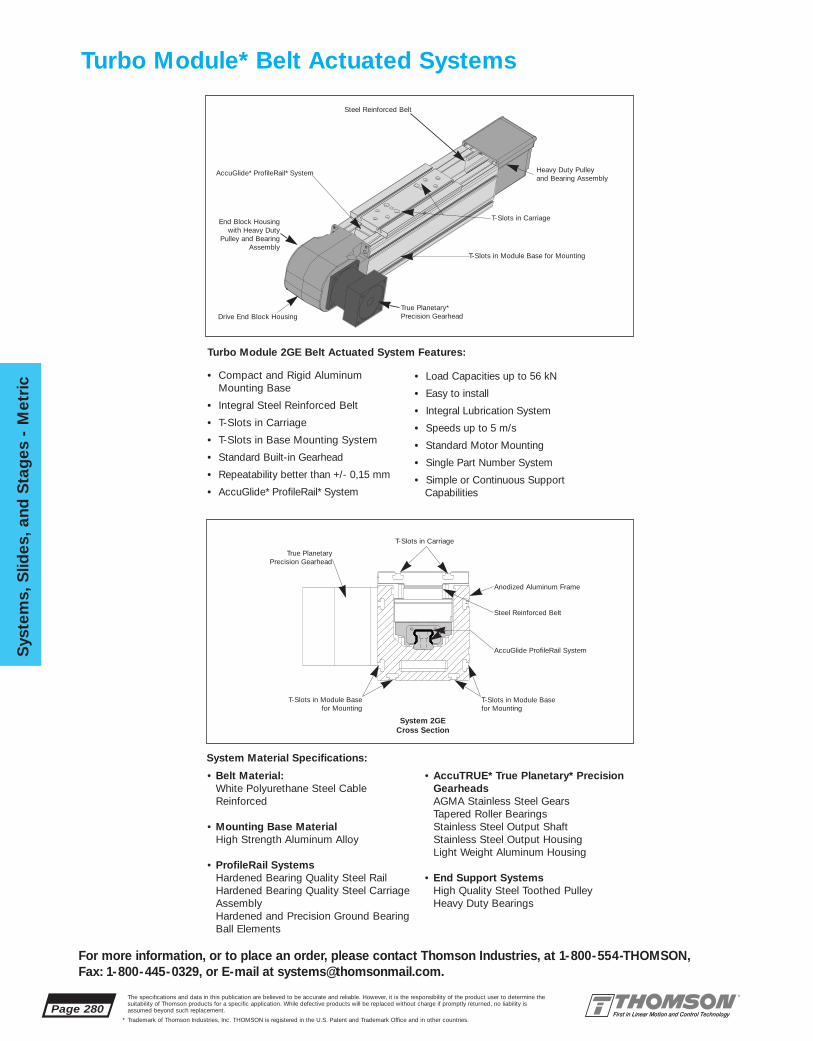
Page 280
Sys
tem
s, S
lides
, and
Sta
ges
- M
etri
c
For more information, or to place an order, please contact Thomson Industries, at 1-800-554-THOMSON, Fax: 1-800-445-0329, or E-mail at [email protected].
The specifications and data in this publication are believed to be accurate and reliable. However, it is the responsibility of the product user to determine thesuitability of Thomson products for a specific application. While defective products will be replaced without charge if promptly returned, no liability isassumed beyond such replacement.
* Trademark of Thomson Industries, Inc. THOMSON is registered in the U.S. Patent and Trademark Office and in other countries.
Turbo Module* Belt Actuated Systems
T-Slots in CarriageEnd Block Housingwith Heavy Duty
Pulley and BearingAssembly
True Planetary*Precision Gearhead
AccuGlide* ProfileRail* System
T-Slots in Module Base for Mounting
Drive End Block Housing
Heavy Duty Pulley and Bearing Assembly
Steel Reinforced Belt
Turbo Module 2GE Belt Actuated System Features:
• Compact and Rigid Aluminum Mounting Base
• Integral Steel Reinforced Belt
• T-Slots in Carriage
• T-Slots in Base Mounting System
• Standard Built-in Gearhead
• Repeatability better than +/- 0,15 mm
• AccuGlide* ProfileRail* System
• Load Capacities up to 56 kN
• Easy to install
• Integral Lubrication System
• Speeds up to 5 m/s
• Standard Motor Mounting
• Single Part Number System
• Simple or Continuous SupportCapabilities
System 2GE Cross Section
T-Slots in Carriage
True Planetary Precision Gearhead
AccuGlide ProfileRail System
T-Slots in Module Basefor Mounting
Anodized Aluminum Frame
Steel Reinforced Belt
T-Slots in Module Basefor Mounting
System Material Specifications:
• Belt Material:White Polyurethane Steel CableReinforced
• Mounting Base MaterialHigh Strength Aluminum Alloy
• ProfileRail SystemsHardened Bearing Quality Steel RailHardened Bearing Quality Steel CarriageAssemblyHardened and Precision Ground BearingBall Elements
• AccuTRUE* True Planetary* Precision GearheadsAGMA Stainless Steel GearsTapered Roller BearingsStainless Steel Output ShaftStainless Steel Output HousingLight Weight Aluminum Housing
• End Support SystemsHigh Quality Steel Toothed PulleyHeavy Duty Bearings

System
s, Slid
es, and S
tages - M
etric
Page 281
For more information, or to place an order, please contact Thomson Industries, at 1-800-554-THOMSON, Fax: 1-800-445-0329, or E-mail at [email protected].
The specifications and data in this publication are believed to be accurate and reliable. However, it is the responsibility of the product user to determine thesuitability of Thomson products for a specific application. While defective products will be replaced without charge if promptly returned, no liability isassumed beyond such replacement.
* Trademark of Thomson Industries, Inc. THOMSON is registered in the U.S. Patent and Trademark Office and in other countries.
Turbo Module* 2GEBelt Actuated Systems
AccuTRUE True Planetary Gear Reduction Features:
• 6 Arc-minutes Maximum Backlash
• Long Service Life
• True Planetary Gearing
• Compact Design
• Ratios Between 1:1 and 50:1
• Up to 90% Efficient
• High Torque Capacity
• Low Inertia
• High Speed Capacity
• Lifetime Lubrication
• Standard Motor Mounting
AccuTRUE True Planetary Precision GearheadMaterials:
• AGMA Stainless Steel Gears
• Tapered Roller Bearings
• Stainless Steel Output Shaft and Housing
• Light Aluminum Input Housing
AccuTRUE* True Planetary GearheadsSpeed reduction choices. True Planetary gearheads are available in standard ratiosbetween 1:1 and 10:1 providing maximum application flexibility. Motor torque capacity is multiplied while outputspeed is reduced. True Planetary gearheads reduce theinertia reflected from the system load and allow for higher accelerations. To specify the proper precision gearhead all that is required is the torque and speed requirements forthe belt actuated system and your selection of a servomotor. Simply follow the step by step selection process on pages 359 through 370.
True Planetary* Gearheads
Stainless Steel Output Shaft
Balanced Collar Clamp and Pinion
Heat Resistant Input Seal
Needle Roller Bearings
LightweightAnodized AluminumHousing
AGMA 12 Hardened StainlessSteel Gears
Motor Input Flange
Tapered Roller Bearings

Page 282
Sys
tem
s, S
lides
, and
Sta
ges
- M
etri
c
For more information, or to place an order, please contact Thomson Industries, at 1-800-554-THOMSON, Fax: 1-800-445-0329, or E-mail at [email protected].
The specifications and data in this publication are believed to be accurate and reliable. However, it is the responsibility of the product user to determine thesuitability of Thomson products for a specific application. While defective products will be replaced without charge if promptly returned, no liability isassumed beyond such replacement.
* Trademark of Thomson Industries, Inc. THOMSON is registered in the U.S. Patent and Trademark Office and in other countries.
Turbo Module 2GEBelt Actuated System
Turbo Module* Multi-Axis OptionsHigh Speed Multi Axis Positioning
The Turbo Module 2GE system provides the basis formulti-axis motion control. The built-in flexibility of the T-slots in the base and the carriage allow for quick and easy x-y, x-z and x-y-z assembly and positioning capability. The illustrations below provide a sampling of the types of configurations that can be achieved. Inmany cases a SuperSlide ball screw actuated systemcan be used to provide an additional axis of motion.Adapter plates can be provided for the mounting ofeach system. For your next multi-axis applicationcontact Thomson Systems application engineering.
2GE-2X-Y 2GE-X-Z
2GE-2X-Y-Z2GE-2X-Z

System
s, Slid
es, and S
tages - M
etric
Page 283
For more information, or to place an order, please contact Thomson Industries, at 1-800-554-THOMSON, Fax: 1-800-445-0329, or E-mail at [email protected].
The specifications and data in this publication are believed to be accurate and reliable. However, it is the responsibility of the product user to determine thesuitability of Thomson products for a specific application. While defective products will be replaced without charge if promptly returned, no liability isassumed beyond such replacement.
* Trademark of Thomson Industries, Inc. THOMSON is registered in the U.S. Patent and Trademark Office and in other countries.
Turbo Module* Belt Actuated SystemSelection Criteria
Many variables influence the selection of a Linear Motion System. The best solutiondemands a thorough evaluation of the application, only then can design criteria be established. Issues such as envelope limitations, system load capacity, actuator loadcapacity, speed and acceleration, drive requirements, accuracy and repeatability, andoperating environment are looked at from a broad perspective to determine the type ofsystem, type of actuator, and whether the system need be built of special materials.
Typically, a belt driven linear motion system is ideal for moderate precision, high load,and high-speed applications. When compared to a Ball Screw Actuated Linear MotionSystem, the Belt Actuated System can attain higher linear speeds in longer stroke applications. A degree of positioning accuracy, however, is sacrificed, as the belt is notcapable of meeting the accuracy of that of the ball screw. The Turbo Module is designedto act as its own support structure by virtue of its robust base support member and isthereby suited for applications that require gantry or overhung loads. Since the TurboModule belt drive is actuated through a True Planetary* gearhead, the torque, speed, andsystem inertia can be matched by varying the gear ratio. In environments that are corrosive or high temperature special materials may be required and are available.Contact Application Engineering for details on special materials.
In order to determine the Turbo Module Belt Actuated SuperSlide* System that meets theneeds of your application, it is first necessary to evaluate the following detail designcriteria:
• System support requirements• System stroke length• Maximum allowable shaft deflection• Required travel life• Force on the most heavily loaded bearing• Load correction factor• Load/Life requirements-linear bearings• Motion (move) profile (velocity, acceleration)• Maximum belt tooth shear strength• Gear motor rotational speed (gear reduction)• Torque considerations• Size motor using torque/speed curves
A detailed explanation of the procedure for selecting a Turbo Module Belt ActuatedLinear Motion System is given on page 359 in the Engineering Support Section.
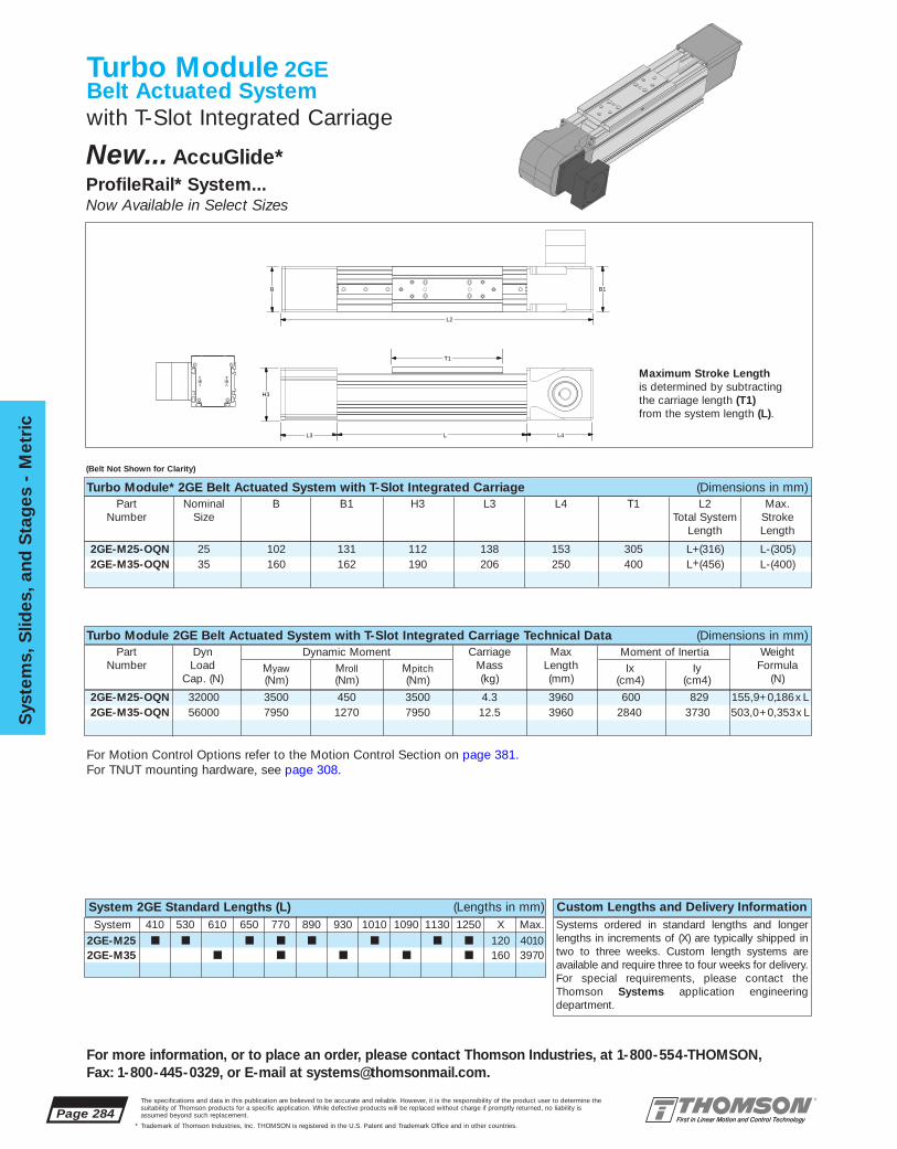
Page 284
Sys
tem
s, S
lides
, and
Sta
ges
- M
etri
c
For more information, or to place an order, please contact Thomson Industries, at 1-800-554-THOMSON, Fax: 1-800-445-0329, or E-mail at [email protected].
The specifications and data in this publication are believed to be accurate and reliable. However, it is the responsibility of the product user to determine thesuitability of Thomson products for a specific application. While defective products will be replaced without charge if promptly returned, no liability isassumed beyond such replacement.
* Trademark of Thomson Industries, Inc. THOMSON is registered in the U.S. Patent and Trademark Office and in other countries.
System 410 530 610 650 770 890 930 1010 1090 1130 1250 X Max.2GE-M25 ■ ■ ■ ■ ■ ■ ■ ■ 120 40102GE-M35 ■ ■ ■ ■ ■ 160 3970
2GE-M25-OQN 32000 3500 450 3500 4.3 3960 600 829 155,9+0,186x L2GE-M35-OQN 56000 7950 1270 7950 12.5 3960 2840 3730 503,0+0,353x L
2GE-M25-OQN 25 102 131 112 138 153 305 L+(316) L-(305)2GE-M35-OQN 35 160 162 190 206 250 400 L+(456) L-(400)
Turbo Module 2GEBelt Actuated Systemwith T-Slot Integrated Carriage
Maximum Stroke Lengthis determined by subtracting the carriage length (T1)from the system length (L).
Turbo Module* 2GE Belt Actuated System with T-Slot Integrated Carriage (Dimensions in mm)Part Nominal B B1 H3 L3 L4 T1 L2 Max.
Number Size Total System StrokeLength Length
System 2GE Standard Lengths (L) (Lengths in mm) Custom Lengths and Delivery InformationSystems ordered in standard lengths and longerlengths in increments of (X) are typically shipped intwo to three weeks. Custom length systems areavailable and require three to four weeks for delivery.For special requirements, please contact theThomson Systems application engineering department.
B B1
L2
H3
L3 L
T1
L4
(Belt Not Shown for Clarity)
New... AccuGlide* ProfileRail* System...Now Available in Select Sizes
Turbo Module 2GE Belt Actuated System with T-Slot Integrated Carriage Technical Data (Dimensions in mm)Part Dyn Dynamic Moment Carriage Max Moment of Inertia Weight
Number Load Myaw Mroll Mpitch Mass Length Ix Iy FormulaCap. (N) (Nm) (Nm) (Nm) (kg) (mm) (cm4) (cm4) (N)
For Motion Control Options refer to the Motion Control Section on page 381.For TNUT mounting hardware, see page 308.

System
s, Slid
es, and S
tages - M
etric
Page 285
For more information, or to place an order, please contact Thomson Industries, at 1-800-554-THOMSON, Fax: 1-800-445-0329, or E-mail at [email protected].
The specifications and data in this publication are believed to be accurate and reliable. However, it is the responsibility of the product user to determine thesuitability of Thomson products for a specific application. While defective products will be replaced without charge if promptly returned, no liability isassumed beyond such replacement.
* Trademark of Thomson Industries, Inc. THOMSON is registered in the U.S. Patent and Trademark Office and in other countries.
2GE-M25-OQN-K 1:1 AT-10-1 7,0 x 10⁻²
2GE-M25-OQN-L 3:1 AT-10-3 2,34 x 10⁻³
2GE-M25-OQN-M 6:1 AT-10-6 1,00 x 10⁻³
2GE-M35-OQN-N 1:1 AT-14-1 1,99 x 10⁻¹
2GE-M35-OQN-P 6:1 AT-14-6 3,43 x 10⁻³
2GE-M35-OQN-Q 10:1 AT-14-10 2,55 x 10⁻³
2GE-M25-OQN 25 65 17,5 75 13,5 110 16,5 8,1 6,8 2,2 129 75 17,5 36 59,5 1082GE-M35-OQN 35 90 37 110 27,5 165 20,1 10 7 6 195 110 27,5 48 90 163
Turbo Module* 2GE Benefits:■ Used in high speed and high
load applications.■ Compact and rigid design
minimizes machine size.■ T-Slot in carriage provides
quick and easy mounting andremoval of the workpiece.
Specifying a Thomson System:1. Determine the proper system for your load and liferequirements. 2. Select the part number. 3. Add the letter “L” followed by the overall length in millimeters, asa suffix to the part number (choosing a standard lengthwill reduce costs and speed delivery). 4.Place yourorder with your local authorized Thomson distributor.Part Numbering System
2GE-M35-OQN-N L610System System LengthDesignation Type of GearboxNominal Size Type of Carriage
Type of Support
Turbo Module 2GE Belt Actuated System with T-Slot Integrated Carriage (Dimensions in mm)Part Nominal B4 B5 B6 B7 B8 D1 D2 D3 D4 H H6 H7 H8 H9 T
Number Size
Turbo Module 2GE Components:■ 1 Structural Frame Assembly with
standard T-Slots for mounting ease.■ 1 AccuGlide* ProfileRail* System
Carriage assembly.■ 1 steel cable reinforced belt system
including heavy duty pulleys and bearings.■ 1 Integral AccuTRUE* True Planetary*
Precision gearhead.
H
H6
H9
H8
H7
T
T9B4B5
B8
B6B7
D2
D3D4
D1
Carriage X-Section
(T9) T-slots
Load/Life GraphLines indicate limiting load for given shaft size
Lo
ad o
n m
ost
hea
vily
load
ed b
eari
ng
(N
)
10100
100
1 000
1 000
10 000
10 000
100 000
100 000
Required Travel Life (km)
2GE-25
2GE-35
System Gear Gearbox GearboxPart Number Ratio Part Number inertia (Kg • m2)
Turbo Module 2GE Gearbox Data
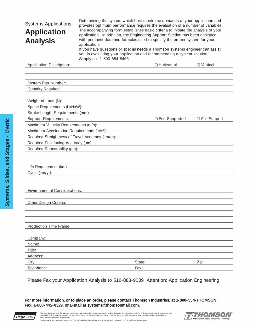
Page 286
Sys
tem
s, S
lides
, and
Sta
ges
- M
etri
c
For more information, or to place an order, please contact Thomson Industries, at 1-800-554-THOMSON, Fax: 1-800-445-0329, or E-mail at [email protected].
The specifications and data in this publication are believed to be accurate and reliable. However, it is the responsibility of the product user to determine thesuitability of Thomson products for a specific application. While defective products will be replaced without charge if promptly returned, no liability isassumed beyond such replacement.
* Trademark of Thomson Industries, Inc. THOMSON is registered in the U.S. Patent and Trademark Office and in other countries.
Systems Applications
ApplicationAnalysis
Determining the system which best meets the demands of your application and provides optimum performance requires the evaluation of a number of variables. The accompanying form establishes basic criteria to initiate the analysis of your application. In addition, the Engineering Support Section has been designed with pertinent data and formulas used to specify the proper system for your application.If you have questions or special needs a Thomson systems engineer can assist you in evaluating your application and recommending a system solution. Simply call 1-800-554-8466.
Application Description: ❑ Horizontal ❑ Vertical
System Part Number:
Quantity Required
Weight of Load (N):
Space Requirements (LxHxW):
Stroke Length Requirements (mm):
Support Requirements: ❑ End Supported ❑ Full Support
Maximum Velocity Requirements (m/s):
Maximum Acceleration Requirements (m/s2):
Required Straightness of Travel Accuracy (µm/m):
Required Positioning Accuracy (µm):
Required Repeatability (µm):
Life Requirement (km):
Cycle (km/yr):
Environmental Considerations:
Other Design Criteria:
Production Time Frame:
Company:
Name:
Title:
Address:
City: State: Zip:
Telephone: Fax:
Please Fax your Application Analysis to 516-883-9039 Attention: Application Engineering
www.thomsonindustries.com
ACCESSORIESACCESSORIES
HARDWARE FOR YOUR APPLICATION• Motor Adaptor and Couplings
• Bellows and Shroud Way Covers• Limit Switch and Sensor Packages
• Electric Brakes• T-Nuts for Multi-Axis adaptation
THOMSON INDUSTRIES, INC.
Accessories for Systems, Slides & Stages, and Motion Control Products
For Application Engineering assistance contact the Thomson Technical HelpLine at 1-800-554-8466.* Trademark of Thomson Industries, Inc. THOMSON is registered in the U.S. Patent and Trademark Office and in other countries. Page 287
Accesso
ries

MC324104760635 BLX232, BLX234 1.26 0.188 0.250 0.55 0.51 1.614 39.8MC324106350635 BLX232, BLX234 1.26 0.250 0.250 0.55 0.51 1.614 39.8MC324109530635 BLX232, BLX234 1.26 0.375 0.250 0.55 0.51 1.614 39.8MC324112700635 BLX232, BLX234 1.26 0.500 0.250 0.55 0.51 1.614 39.8MC456309531270 BLX341, BLX342, BLX343 1.77 0.375 0.500 0.47 0.95 2.48 159.3MC456312701270 BLX341, BLX342, BLX343 1.77 0.500 0.500 0.47 0.95 2.48 159.3MC667815881900 BLX421 2.60 0.625 0.748 0.77 0.79 3.07 354.0MC667815882400 BLX422, BLX423 2.60 0.625 0.945 0.77 0.79 3.07 354.0
MC-BEL-12-23 NEMA 23 .98 .250 .250 .51 .24 1.26 17.7MC-BEL-16-23 NEMA 23 .98 .250 .375 .51 .24 1.26 17.7MC-BEL-16-34 NEMA 34 1.57 .375 .375 .67 .51 1.85 88.5MC-BEL-16-34 AE NEMA 34 1.57 .375 .500 .67 .51 1.85 88.5MC-BEL-24-42 NEMA 42 1.77 .625 .625 .47 1.54 2.48 159.3
MC-OLD-12-23 NEMA 23 1.00 .250 .250 .46 .36 1.28 30.1MC-OLD-16-23 NEMA 23 1.00 .250 .375 .46 .36 1.28 30.1MC-OLD-16-34 NEMA 34 1.31 .375 .375 .59 .71 1.89 79.6MC-OLD-16-34 AE NEMA 34 1.31 .375 .500 .59 .71 1.89 79.6MC-OLD-24-42 NEMA 42 1.63 .625 .625 .70 .60 2.00 159.3
Page 288The specifications and data in this publication are believed to be accurate and reliable. However, it is the responsibility of the product user to determine thesuitability of Thomson products for a specific application. While defective products will be replaced without charge if promptly returned, no liability isassumed beyond such replacement.
* Trademark of Thomson Industries, Inc. THOMSON is registered in the U.S. Patent and Trademark Office and in other countries.
Acc
esso
ries
For more information, or to place an order, please contact Thomson Industries, at 1-800-554-THOMSON, Fax: 1-800-445-0329, or E-mail at [email protected].
Aluminum Oldham Type with Clamp Attachment (Acetal Disc)Part Motor Dimensions (in.) Maximum
Number Size D5 D4 D8 L1 L2 L9 Torque (lbf-in)
Couplings and Motor Adaptor Blocks
Motor Couplings for Mounting NEMA frame size motors to Inch Size Systems
Motor Couplings for Mounting BLX Series Servo Motors to Inch Size Systems
Stainless Steel Bellows Type with Clamp Attachment Part Motor Dimensions (in.) Maximum
Number Size D5 D4 D8 L1 L2 L9 Torque (lbf-in)
Stainless Steel Bellows Type with Clamp Attachment Coupling Motor Dimensions (in.) MaximumPart No. Part No. D5 D4 D8 L1 L2 L9 Torque (lbf-in)
D4 D8 D5
L1
discL9
L2
D8D4D5
L1L2
L9
D8D4D5
L1L2
L9
For Dimensional information and specifications of BLX series servo motors, see page 431.
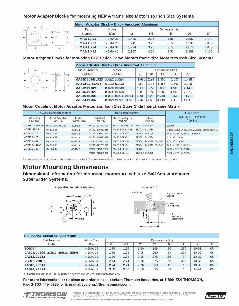
2DB08
2AB08, 2CB08, 2CB12, 2DB12, 2EB08, BSA08, BSAM12
2AB12, 2EB12, BSA12, BSAM20
2CB16†, 2DB16†
2CB16†, 2DB16†
2AB16, 2EB16, BSA16
2AB24, 2EB24, BSA24
2AB24, 2EB24, BSA24
MAB2DB08-BLX23 BLX232, BLX234 1.685 2.24 1.856 1.503 1.498 MAB08/12-BLX23 BLX232, BLX234 1.59 2.24 1.856 1.503 2.148MAB12-BLX23 BLX232, BLX234 1.41 2.24 1.856 1.503 2.148MAB16-BLX23 BLX232, BLX234 1.40 3.26 2.740 1.503 2.875MAB16-BLX34 BLX341, BLX342, BLX343 2.40 3.26 2.740 2.878 2.875MAB24-BLX42 BLX421, BLX422, BLX423 3.40 4.50 3.619 4.332 4.099
MAB 12-23 NEMA 23 1.425 2.24 1.86 1.503 2.149MAB 16-23 NEMA 23 1.245 3.26 2.74 1.503 2.875MAB 16-34 NEMA 34 1.994 3.26 2.74 2.878 2.875MAB 24-42 NEMA 42 2.285 4.38 3.50 2.189 4.100
2DB08† NEMA 23 1.75 1.25 1.50 .188 .30 .275 10-32 .052AB08, 2CB08, 2CB12, 2DB12, 2EB08 NEMA 23 1.86 1.86 2.15 .250 .34 .300 10-32 .052AB12, 2EB12 NEMA 23 1.86 1.86 2.15 .375 .56 0 10-32 .052CB16, 2DB16 NEMA 34 2.74 2.74 2.88 .375 .56 .425 10-32 .052AB16, 2EB16 NEMA 34 2.74 2.74 2.88 .500 .42 0 10-32 .052AB24, 2EB24 NEMA 42 3.50 3.50 4.10 .625 .59 0 1/4-20 .05
The specifications and data in this publication are believed to be accurate and reliable. However, it is the responsibility of the product user to determine thesuitability of Thomson products for a specific application. While defective products will be replaced without charge if promptly returned, no liability isassumed beyond such replacement.
* Trademark of Thomson Industries, Inc. THOMSON is registered in the U.S. Patent and Trademark Office and in other countries.
Accesso
ries
Page 289
For more information, or to place an order, please contact Thomson Industries, at 1-800-554-THOMSON, Fax: 1-800-445-0329, or E-mail at [email protected].
Motor Mounting DimensionsDimensional Information for mounting motors to Inch size Ball Screw ActuatedSuperSlide* Systems.
Ball Screw Actuated SuperSlide
† Dimensions for the 2DB08 SuperSlide system are for lead screw actuation only.
P
D3
D1
K
E
BearingLocking Ring
Angular ContactBearing
Ball Screw
(for motor attachment)
Part Number Motor Size Dimensions (in.)Prefix Size C1 C2 D1 D3 E J K P
SuperSlide End Block End View Section A-A
Motor Adaptor Blocks for mounting NEMA frame size Motors to Inch Size Systems
Motor Adaptor Blocks for mounting BLX Series Servo Motors frame size Motors to Inch Size Systems
Motor Coupling, Motor Adaptor, Motor, and Inch Size SuperSlide Interchange Matrix
Motor Adaptor Block – Black Anodized AluminumPart Motor Dimension (in.)
Number Size L8 H5 H8 D6 D7H8 D6H5 D7
L8H5
H8
H8 D6H5 D7
L8H5
H8
† Accessories for 2CB-16 and 2DB-16 Systems available for both NEMA 23 and NEMA 34 or BLX 23X and BLX 34X frame size motors.
Motor Adaptor Block - Black Anodized AluminumMotor Adaptor Motor Dimensions (in.)
Part No. Part No. L8 H5 H8 D6 D7
MC324104760635
MCBEL 12-23
MCBEL12-23
MCBEL16-23
MCBEL16-34
MCBEL16-34AE
MCBEL24-42
MAB2DB08-BLX23
MAB12-23
MAB12-23
MAB16-23
MAB16-34
MAB16-34
MAB24-42
NEMA23
NEMA23
NEMA23
NEMA23
NEMA34
NEMA34
NEMA42
Coupling Part No.
Motor AdaptorPart No.
Motor Frame Size
NEMA frame size motors
MC324104760635
MC324106350635
MC324106350635
MC324109530635
MC456309531270
MC456312701270
MC667815881900
MC667815882400
MAB2DB08-BLX23
MAB08/12-BLX23
MAB12-BLX23
MAB16-BLX23
MAB16-BLX34
MAB16-BLX34
MAB24-BLX42
MAB24-BLX42
BLX232, BLX234
BLX232, BLX234
BLX232, BLX234
BLX232, BLX234
BLX341, BLX342, BLX343
BLX341, BLX342, BLX343
BLX421
BLX422, BLX423
Coupling Part No.
Motor AdaptorPart No.
Motor Part No.
BLX series motors Used withSuperSlide System
Part No.

MCM-BEL-08-23MCM-BEL-10-23MCM-BEL-10-34-GBMCM-BEL-10-23MCM-BEL-10-34-GBMCM-BEL-08-23MCM-BEL-14-34-GBMCM-BEL-14-421MCM-BEL-14-422
MCM-BEL-08-23 NEMA 23 25 6,35 8 13 6 32 2,0MCM-BEL-10-23 NEMA 23 25 6,35 10 13 6 32 2,0MCM-BEL-14-34 NEMA 34 40 9,53 14 17 13 47 10,0
2RB M12 NEMA 23 60,0 47,15 60,0 38,2 8,0 42,0 34,02RB M16 NEMA 23 60,0 47,15 60,0 38,2 10,0 42,5 32,52NB M20 NEMA 23 60,0 47,15 60,0 38,2 10,0 42,5 32,52HB M10 NEMA 23 60,0 47,15 60,0 38,2 8,0 42,0 34,02HB M20 NEMA 34 88,9 69,6 88,9 73,10† 14,0 66,0 52,0
MCM-OLD-08-23 NEMA 23 25,4 6,35 8 11,6 9,2 32,4 3,4MCM-OLD-10-23 NEMA 23 25,4 6,35 10 11,6 9,2 32,4 3,4MCM-OLD-14-34 NEMA 34 41,3 9,53 14 15,0 18,0 48,0 9,0
Page 290The specifications and data in this publication are believed to be accurate and reliable. However, it is the responsibility of the product user to determine thesuitability of Thomson products for a specific application. While defective products will be replaced without charge if promptly returned, no liability isassumed beyond such replacement.
* Trademark of Thomson Industries, Inc. THOMSON is registered in the U.S. Patent and Trademark Office and in other countries.
Acc
esso
ries
For more information, or to place an order, please contact Thomson Industries, at 1-800-554-THOMSON, Fax: 1-800-445-0329, or E-mail at [email protected].
Motor Mounting Dimensions
Ball Screw Actuated SuperSlidePart Motor Dimension (mm)
Number Size B3 C3 H4 D1 D3 E P
Dimensional Information for mounting of NEMA frame size motors to Metric size Ball Screw Actuated SuperSlide* Systems
H4
C3
C3B3
† ∅ DI is for the first 5mm only; remainder is ∅ 50.8mm
Metric Motor Couplings
Aluminum Oldham Type with Clamp Attachment (Acetal Disc)Part Motor Dimension (mm) Maximum
Number Size D5 D4 D8 L1 L2 L9 Torque (N • m)
Motor Couplings for Mounting NEMA frame size motors to Metric Size Systems
Motor Couplings for Mounting BLX Series Servo Motors to Metric Size Systems
D4 D8 D5
L1
discL9
L2
D8D4D5
L1L2
L9
Stainless Steel Bellows Type with Clamp Attachment Part Motor Dimension (mm) Maximum
Number Size D5 D4 D8 L1 L2 L9 Torque (N • m)
E
P
D1 D3
System Model Thomson Motor Model Motor Adaptor Block Shaft Coupling
2RBM122RBM16
2NBM20
2HBM102HBM20
BLX23BLX23BLX34BLX23BLX34BLX23BLX34BLX421BLX422, BLX423
None RequiredNone RequiredMABM34None RequiredMABM34None RequiredNone RequiredMABM42MABM42
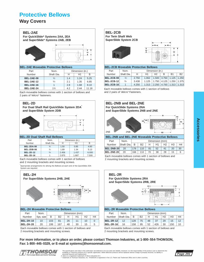
BEL-2CB-08 1/2 2.750 1.062 1.500 3.750 1.125 1.250BEL-2CB-12 3/4 3.438 1.125 1.750 4.125 1.250 1.375BEL-2CB-16 1 4.250 1.313 2.250 4.750 1.313 1.313
BEL-2R-12 12 128 75 48 37 29 15 12BEL-2R-16 16 158 95 52 426 30 150 10
BEL-2DA-08 1/2 1.50 0.85 4.60BEL-2DB-08 1/2 1.89 1.34 5.13BEL-2D-12 3/4 2.406 1.437 6.000BEL-2D-16 1 2.875 1.687 7.500
The specifications and data in this publication are believed to be accurate and reliable. However, it is the responsibility of the product user to determine thesuitability of Thomson products for a specific application. While defective products will be replaced without charge if promptly returned, no liability isassumed beyond such replacement.
® Velcro is a registered trademark of Velcro Industries B.V.* Trademark of Thomson Industries, Inc. THOMSON is registered in the U.S. Patent and Trademark Office and in other countries.
Accesso
ries
Page 291
For more information, or to place an order, please contact Thomson Industries, at 1-800-554-THOMSON, Fax: 1-800-445-0329, or E-mail at [email protected].
Protective BellowsWay Covers
BEL-2AEFor QuickSlide* Systems 2AA, 2EA and SuperSlide* Systems 2AB, 2EB
BEL-2AE Moveable Protective BellowsPart Nom. Dimension (in.)
Number Shaft Dia. H H1 B
BEL-2AE-08 1/2 1.4 1.24 5.25BEL-2AE-12 3/4 2.1 1.35 6.85BEL-2AE-16 1 2.8 1.68 8.10BEL-2AE-24 11/2 4.2 2.44 11.18
BEL-2HFor SuperSlide Systems 2HB, 2HE
BEL-2H Moveable Protective BellowsPart Nom. Dimension (mm)
Number Sys. size B B2 H H1 H2 H4
BEL-2H-10 10 103 81 26 11 10 0BEL-2H-20 20 199 167 48 30 15 5
B2
H3 H4
H2
B
HH1
B
H
H1
B2
H
B
H1H2
H4
BEL-2RFor QuickSlide Systems 2RA and SuperSlide Systems 2RB, 2RE
BEL-2R Moveable Protective BellowsPart Nom. Dimension (mm)
Number Shaft Dia. B B2 H H1 H2 H3 H4
Each moveable bellows comes with 1 section of bellows and2 pairs of Velcro® fasteners.
Each moveable bellows comes with 1 section of bellows and2 mounting brackets and mounting screws.
Each moveable bellows comes with 1 section of bellows and2 mounting brackets and mounting screws.
Each moveable bellows comes with 1 section of bellows and2 mounting brackets and mounting screws.
BEL-2NB and BEL-2NEFor QuickSlide Systems 2NA and SuperSlide Systems 2NB and 2NE
BEL-2NB and BEL-2NE Moveable Protective BellowsPart Nom. Dimension (mm)
Number Shaft Dia. B B2 H H1 H2 H3 H4
BEL-2NE-20 20 166 110 70 38 28 15 6
B2
H3H2
B
HH1
H4
BEL-2NB-20 20 176 110 81 52 41 20 30
B
B1 B2
H
H2H1
BEL-2CBFor Twin Shaft WebSuperSlide System 2CB
BEL-2CB Moveable Protective BellowsPart Nom. Dimension (in.)
Number Shaft Dia. H H1 H2 B B1 B2
Each moveable bellows comes with 1 section of bellows and 2 pairs of Velcro® Fasteners.
Each moveable bellows comes with 1 section of bellows and 2 mounting brackets and mounting screws.†Appropriate arrangements for afixing the Bellows at each end of the QuickSlide 2DASystem are required.
B
H
H1
BEL-2DFor Dual Shaft Rail QuickSlide System 2DA
†
and SuperSlide System 2DB
BEL-2D Dual Shaft Rail BellowsPart Nom. Dimension (in.)
Number Shaft Dia. H H1 B
2NB2NE

Page 292The specifications and data in this publication are believed to be accurate and reliable. However, it is the responsibility of the product user to determine thesuitability of Thomson products for a specific application. While defective products will be replaced without charge if promptly returned, no liability isassumed beyond such replacement.
* Trademark of Thomson Industries, Inc. THOMSON is registered in the U.S. Patent and Trademark Office and in other countries.
Acc
esso
ries
For more information, or to place an order, please contact Thomson Industries, at 1-800-554-THOMSON, Fax: 1-800-445-0329, or E-mail at [email protected].
• Allows for the mounting of actuating devicesthat will impart a cantilever load to the ballscrew shaft extension.
• May be used with:– Pulley and Belt Drives– Hand Cranks– Pinion Gears
• Radial Mount* couplings provide attachment ofball screw and extender shafts without the need for painstaking alignment procedures.
• The heavy duty cantilever torque capacity ofthe Radial Mount shaft extender resists ballscrew stub shaft fatigue and failure.
Radial Mount BallBall Screw Shaft Extenders for SuperSlide* Systems

The specifications and data in this publication are believed to be accurate and reliable. However, it is the responsibility of the product user to determine thesuitability of Thomson products for a specific application. While defective products will be replaced without charge if promptly returned, no liability isassumed beyond such replacement.
* Trademark of Thomson Industries, Inc. THOMSON is registered in the U.S. Patent and Trademark Office and in other countries.
Accesso
ries
Page 293
For more information, or to place an order, please contact Thomson Industries, at 1-800-55-4-THOMSON, Fax: 1-800-445-0329, or E-mail at [email protected].
Radial Mount* Shaft Extender Technical Information
RADMO-23A††† 120 .5 NEMA-23 2.24 1.86 1.75 2.15 1.12 .93 3.625 2.15 .25 .16 1.15 .62 .22 1.26 .626 .626 .43RADMO-23B 120 .5 NEMA-23 2.24 1.86 1.75 2.15 1.12 .93 3.625 2.15 .25 .16 1.15 .62 .22 1.26 .626 .626 .43RADMO-23C 120 .5 NEMA-23 2.24 1.86 1.75 2.15 1.12 .93 3.625 2.15 .25 .16 1.15 .62 .22 1.26 .626 .626 .43RADMO-34A 120 .5 NEMA-34 3.26 2.74 1.75 2.88 1.63 1.37 3.625 3.0 .25 .16 1.2 .50 .22 1.26 .626 .626 .48RADMO-34B 120 .5 NEMA-34 3.26 2.74 1.75 2.88 1.63 1.37 3.625 3.0 .25 .16 1.2 .50 .22 1.26 .626 .626 .48RADMO-42A 210 1.0 NEMA-42 4.19 3.50 2.37 4.10 2.09 1.75 4.225 3.5 .38 .16 1.43 .50 .27 2.19 .747 .747 .68
FR†
Part Max. J Frame Dimensions (in.)
Number (lbf.) (in.) Size A B C D E F G H K L M N P S V1 V2 Q
B C V1 V2flD
B
Q
F
F
A H
J
E
NP
AE
X
X
G
M
FR
S
LK
Section X-X
3/16SquareKeyway
Output shaft is a non-hardened steel.
Radial MountBall Screw Shaft Extenders for SuperSlide* Systems
D2
L1
D1D3
disc
Radial Mount CouplingsCouples the SuperSlide Ball Screw shaftto the Smart Mount Shaft Extender
† Based on a bearing life of 2 x 10⁸ revolutions.††Radial Mount shaft extenders are supplied with their corresponding Radial Mount Coupling.
††† The RADMO-23A shaft extender is supplied with an adaptor block part number MB08-23.
Dimensions (in.) SuppliedMax. Used with
Part Torque with Smart MountNumber in-lbf. L1 D1 D2 D3 System Extender
RMC-23A††† 80 1.89 .188 .626 1.31 2DB08 RADMO-23ARMC-23B 80 1.89 .250 .626 1.31 2AB08, 2CB08, 2CB12, 2DB12, 2EB08, BSA08, BSAM12 RADMO-23BRMC-23C 80 1.89 .375 .626 1.31 2AB12, 2EB12, BSA12, BSAM20 RADMO-23CRMC-34A 80 1.89 .375 .626 1.31 2CB16, 2DB16 RADMO-34ARMC-34B 160 2.00 .500 .626 1.63 2AB16, 2EB16, BSA16 RADMO-34BRMC-42A 230 2.35 .625 .748 1.97 2AB24, 2EB24, BSA24 RADMO-42A
Radial Mount Coupling Technical Information

Page 294The specifications and data in this publication are believed to be accurate and reliable. However, it is the responsibility of the product user to determine thesuitability of Thomson products for a specific application. While defective products will be replaced without charge if promptly returned, no liability isassumed beyond such replacement.
* Trademark of Thomson Industries, Inc. THOMSON is registered in the U.S. Patent and Trademark Office and in other countries.
Acc
esso
ries
For more information, or to place an order, please contact Thomson Industries, at 1-800-554-THOMSON, Fax: 1-800-445-0329, or E-mail at [email protected].
2DA QuickSlide* System with Brake offers:
• A manual locking mechanism withinfinite positioning capability.
• No carriage mounting surface deflection when the locking mechanism is activated.
• Immediate off-the-shelf availability in1/2, 3/4 and 1 inch sizes.
• A locking mechanism that, when activated, will not apply an increase inload on the system’s Ball Bushing*bearing.
• Zero axial movement during the activation of the locking mechanism.
• A fully supported Dual Shaft assemblyfor maximum rigidity and unlimitedtravel.
• High load capacity in any direction.
2DA QuickSlide System with BrakeA manual locking mechanism for the Dual Shaft Rail System

System 8” 12” 16” 18” 20” 24” 28” 30” 32” 36” 40” 42” 44” 48”2DA-08 ■ ■ ■ ■ ■ ■ ■ ■ ■ ■ ■
2DA-12 ■ ■ ■ ■ ■ ■ ■
2DA-08-OOM 1⁄2 3.50 3.00 L-(5.13) DSRC-08-SM2DA-12-OOM 3⁄4 4.50 3.75 L-(6.13) DSRC-12-SM2DA-16-OOM 1 6.00 5.25 L-(7.63) DSRC-16-SM
2DA-08 1252DA-12 1302DA-16 140
2DA-08-OOL 4.00 0.25 4.00 0.30 4.00 2.00 0.75 1.63 1.19 0.88 #10-23 1⁄4 0.28 L-(6.13) DSRC-08-SL2DA-12-OOL 5.25 0.37 5.25 0.42 6.00 3.00 1.00 1.63 1.19 1.00 1⁄4-20 5⁄16 0.34 L-(7.63) DSRC-12-SL2DA-16-OOL 6.75 0.37 6.75 0.42 6.00 3.00 1.25 1.63 1.19 1.00 5⁄16-18 3⁄8 0.41 L-(9.13) DSRC-16-SL
2DA-08-OOL 1⁄2 600 150 4.50 1.625 0.875 1.43 2.00 0.500 4.60 3.00 0.64 1.252DA-12-OOL 3⁄4 1880 470 6.00 2.125 1.125 1.93 2.63 0.688 6.10 4.00 0.75 1.622DA-16-OOL 1 3120 780 7.50 2.625 1.375 2.44 3.25 0.875 7.60 5.00 0.99 2.00
The specifications and data in this publication are believed to be accurate and reliable. However, it is the responsibility of the product user to determine thesuitability of Thomson products for a specific application. While defective products will be replaced without charge if promptly returned, no liability isassumed beyond such replacement.
* Trademark of Thomson Industries, Inc. THOMSON is registered in the U.S. Patent and Trademark Office and in other countries.
Accesso
ries
Page 295
For more information, or to place an order, please contact Thomson Industries, at 1-800-554-THOMSON, Fax: 1-800-445-0329, or E-mail at [email protected].
2DA QuickSlide*
System with Brake
Dual Shaft Rail Fully Supported Systemwith Integrated Carriage and Locking Mechanism
F M1
X Y
Z
G
M
N N1
L
T1
J1
J2C1
C
Dual Shaft Rail Fully Supported System with Integrated Carriage (Long Style) (Dimensions in inches)Part N N1 M M1 X Y Z J1 J2 J3 F G Max. Carriage
Number Bolt Hole Stroke PartLength No.
Dual Shaft Rail Fully Supported System with Integrated Carriage (Long Style) (Dimensions in inches)Part Nom. Max.Load Max.Load on T1 H H1 H2 B R B1 B2 C C1
Number Shaft on System(1) One Bearing(1)
Dia. (lbf) (lbf)
Dual Shaft Rail Fully Supported System with Integrated Carriage (Short Style)Part Nom. T2 N2 Max. Carriage
Number Shaft Stroke PartDia. Length No.
QuickSlide Brake Holding ForceSystem Axial Holding Force (lbf.)
Dual Shaft Rail Fully SupportedSystem with Integrated Carriage
Dual Shaft Rail SupportedCross-Section
Maximum Stroke Lengthis determined by subtracting thecarriage length (T1 or T2) plus thebrake handle length (J1) from thetotal system length.
B1
S
B2
H1
BR
H2 H
J3
Systems ordered in standard lengths andlonger lengths in increments of (X) are typicallyshipped in two to three weeks. Custom lengthsystems are available and require three to fourweeks for delivery. For special requirements,please contact the Thomson Systems application engineering department.
Custom Lengths and Delivery InformationSystem 2DA Standard Lengths (Lengths in inches)
(1) For rated travel life of 2 million inches.
Note: Manual Brake can be adjusted in order to position handle to any radial location.Dual Shaft Rail Support Material: Aluminum Alloy Black Anodized. Standard length of one-piece Aluminum Dual Shaft Rails is 72”.

Limit Switch/Sensor Package for AccuSlide* 2HBM10 System
An inductive proximity sensorfor end of travel limit and home position sensing. Standard part numbers are packages for either home positioning, end of travel limits or both home and end of travel limit sensing together. Options include NPN or PNP output types, normally closed or normally open output operations, and standard or varied frequencies. All sensors include 12-24 VDC supply voltages and 5 meter length cables.
End Plates not shown for clarity
End Plates not shown for clarity
Each 2HBM10 AccuSlide system is provided with access holes on each side of each end plate forpassage of the sensor cable. Normal orientation of the sensor package will detract approximately30mm from the effective stroke of the system at each end. Orientation of the sensor can bereversed so as to retain full system stroke. When Limit and Home Sensor Packages are orderedtogether with their respective Linear Motion System, the package is assembled to the system withtheir appropriate shim packs at no extra charge. When the End of Travel Limit Sensors are orderedin conjunction with the Home Position Sensor (the -3 option) the Home Sensor will be locatedbetween the Limit Sensors on the Linear Motion System.
Page 296The specifications and data in this publication are believed to be accurate and reliable. However, it is the responsibility of the product user to determine thesuitability of Thomson products for a specific application. While defective products will be replaced without charge if promptly returned, no liability isassumed beyond such replacement.
* Trademark of Thomson Industries, Inc. THOMSON is registered in the U.S. Patent and Trademark Office and in other countries.
Acc
esso
ries
For more information, or to place an order, please contact Thomson Industries, at 1-800-554-THOMSON, Fax: 1-800-445-0329, or E-mail at [email protected].
Part Number
LSP2HBM10-N-1LSP2HBM10-P-1
(1) NPN(1) PNP
(1) Normally Open(1) Normally Open
(1) Varied(1) Varied
(2) NPN(2) PNP
(1) Normally Closed(1) Normally Closed
(1) Standard(1) Standard
(3) NPN(3) PNP
(1) N.O., (2) N.C.(1) N.O., (2) N.C.
(1) Var. (2) Std(1) Var. (2) Std
LSP2HBM10-N-2LSP2HBM10-P-2
LSP2HBM10-N-3LSP2HBM10-P-3
Output Type Output Operation Frequency
Home Sensor
End of Travel Sensors
Home Sensor & End of Travel Sensors
Item
12345
11211
Proximity SensorSensor BracketTee Nut (TNUT01-M3)Button Head Cap ScrewShim Kit
Quantity Description
Dimension “A”(mm)
up to 8.158.16-8.658.66-9.159.16-9.65
up to .320.321-.340.341-.360.361-.380
none22723A-0222723A-0422723A-02+22723A-04
0.51mm (0.20”)1.02mm (0.40”)1.52mm (0.60”)
Dimension “A”(in.)
Shim Part No.
Shim Thickness
1
2
3
45
’’AA ’’

Limit Switch/Sensor Package for AccuSlide* 2HEM10 System
An inductive proximity sensorfor end of travel limit and homeposition sensing. Standard part numbers are packages for either home positioning,end of travel limits or bothhome and end of travel limit sensing together. Optionsinclude NPN or PNP output types, normally closed or normally open output operations,and standard or varied frequencies.All sensors include 12-24 VDCsupply voltages and 5 meter length cables.
End Plates not shown for clarity
Each 2HEM10 AccuSlide system is provided withaccess holes on each side of each end plate forpassage of the sensor cable. Normal orientation ofthe sensor package will detract approximately30mm from the effective stroke of the system ateach end. Orientation of the sensor can be reversedso as to retain full system stroke. When Limit andHome Sensor Packages are ordered together withtheir respective Linear Motion System, the package is assembled to the system at no extra charge. When the End of Travel Limit Sensors are ordered in conjunction with the Home Position Sensor (the -3 option) the Home Sensor will be located between the Limit Sensors on the Linear Motion System.
The specifications and data in this publication are believed to be accurate and reliable. However, it is the responsibility of the product user to determine thesuitability of Thomson products for a specific application. While defective products will be replaced without charge if promptly returned, no liability isassumed beyond such replacement.
* Trademark of Thomson Industries, Inc. THOMSON is registered in the U.S. Patent and Trademark Office and in other countries.
Accesso
ries
Page 297
For more information, or to place an order, please contact Thomson Industries, at 1-800-554-THOMSON, Fax: 1-800-445-0329, or E-mail at [email protected].
Part Number
LSP2HEM10-N-1LSP2HEM10-P-1
(1) NPN(1) PNP
(1) Normally Open(1) Normally Open
(1) Varied(1) Varied
(2) NPN(2) PNP
(1) Normally Closed(1) Normally Closed
(1) Standard(1) Standard
(3) NPN(3) PNP
(1) N.O., (2) N.C.(1) N.O., (2) N.C.
(1) Var. (2) Std(1) Var. (2) Std
LSP2HEM10-N-2LSP2HEM10-P-2
LSP2HEM10-N-3LSP2HEM10-P-3
Output Type Output Operation Frequency
Home Sensor
End of Travel Sensors
Home Sensor & End of Travel Sensors
Item
1234567
1121112
Proximity SensorSensor BracketTee Nut (TNUT01-M3)Button Head Cap Screw (M3)Sensor FlagSensor Flag NutplateLow Head Cap Screw (M5)
Quantity Description
End Plates not shown for clarity
22
33
11 44
66
55
77

Limit Switch/Sensor Package for AccuSlide*2HBM20 System
An inductive proximity sensorfor end of travel limit and home position sensing. Standard part numbers are packages for either home positioning, end of travel limits or both home and end of travel limit sensing together. Options include NPN or PNP output types, normally closed or normally open output operations, and standard or varied frequencies. All sensors include 12-24 VDC supply voltages and 5 meter length cables.
End Plates not shown for clarity
Each 2HBM20 AccuSlide system is provided with access holes on each side of each endplate for passage of the sensor cable. Normalorientation of the sensor package will detractapproximately 30mm from the effective strokeof the system at each end. Orientation of the sensor can be reversed so as to retain full system stroke. When Limit and Home Sensor Packages are ordered together with their respective Linear Motion System, the packageis assembled to the system with theirappropriate shim packs at no extra charge. When the End of Travel Limit Sensors are ordered in conjunction with the Home PositionSensor (the -3 option) the Home Sensor willbe located between the Limit Sensors onthe Linear Motion System.
Page 298The specifications and data in this publication are believed to be accurate and reliable. However, it is the responsibility of the product user to determine thesuitability of Thomson products for a specific application. While defective products will be replaced without charge if promptly returned, no liability isassumed beyond such replacement.
* Trademark of Thomson Industries, Inc. THOMSON is registered in the U.S. Patent and Trademark Office and in other countries.
Acc
esso
ries
For more information, or to place an order, please contact Thomson Industries, at 1-800-554-THOMSON, Fax: 1-800-445-0329, or E-mail at [email protected].
Part Number
LSP2HBM20-N-1LSP2HBM20-P-1
(1) NPN(1) PNP
(1) Normally Open(1) Normally Open
(1) Varied(1) Varied
(2) NPN(2) PNP
(1) Normally Closed(1) Normally Closed
(1) Standard(1) Standard
(3) NPN(3) PNP
(1) N.O., (2) N.C.(1) N.O., (2) N.C.
(1) Var. (2) Std(1) Var. (2) Std
LSP2HBM20-N-2LSP2HBM20-P-2
LSP2HBM20-N-3LSP2HBM20-P-3
Output Type Output Operation Frequency
Home Sensor
End of Travel Sensors
Home Sensor & End of Travel Sensors
Item
12345
11222
Proximity SensorSensor Mounting PlateTee Nut (TNUT01-M3)Button Head Cap Screw (M3)Button Head Cap Screw (M3)
Quantity Description
2
3
41
5
End Plates not shown for clarity

Limit Switch/Sensor Package for AccuSlide* 2HEM20 System
An inductive proximity sensorfor end of travel limit and home position sensing. Standard part numbers are packages for either home positioning, end of travel limits or both home and end of travel limit sensing together. Options include NPN or PNP output types, normally closed or normally open output operations, and standard or varied frequencies. All sensors include 12-24 VDC supply voltages and 5 meter length cables.
End Plates not shown for clarity
Each 2HEM20 AccuSlide system is provided withaccess holes on each side of each end plate for passageof the sensor cable. Normal orientation of the sensor package will detract approximately 30mm from the effective stroke of the system at each end. Orientation of the sensor can bereversed so as to retain full system stroke. When Limit and Home Sensor Packages areordered together with their respective Linear Motion System, the package is assembled tothe system at no extra charge. When theEnd of Travel Limit Sensors are ordered inconjunction with the Home Position Sensor (the -3 option) the Home Sensor will belocated between the Limit Sensors on theLinear Motion System.
The specifications and data in this publication are believed to be accurate and reliable. However, it is the responsibility of the product user to determine thesuitability of Thomson products for a specific application. While defective products will be replaced without charge if promptly returned, no liability isassumed beyond such replacement.
* Trademark of Thomson Industries, Inc. THOMSON is registered in the U.S. Patent and Trademark Office and in other countries.
Accesso
ries
Page 299
For more information, or to place an order, please contact Thomson Industries, at 1-800-554-THOMSON, Fax: 1-800-445-0329, or E-mail at [email protected].
Part Number
LSP2HEM20-N-1LSP2HEM20-P-1
(1) NPN(1) PNP
(1) Normally Open(1) Normally Open
(1) Varied(1) Varied
(2) NPN(2) PNP
(1) Normally Closed(1) Normally Closed
(1) Standard(1) Standard
(3) NPN(3) PNP
(1) N.O., (2) N.C.(1) N.O., (2) N.C.
(1) Var. (2) Std(1) Var. (2) Std
LSP2HEM20-N-2LSP2HEM20-P-2
LSP2HEM20-N-3LSP2HEM20-P-3
Output Type Output Operation Frequency
Home Sensor
End of Travel Sensors
Home Sensor & End of Travel Sensors
Item
12345678
11222122
Proximity SensorSensor Mounting PlateTee Nut (TNUT01-M3)Button Head Cap Screw (M3)Button Head Cap Screw (M3)Sensor FlagHat WasherLow Head Cap Screw (M4)
Quantity Description
12
3
4
5
6
7
8
End Plates not shown for clarity

For more information, or to place an order, please contact Thomson Industries, at 1-800-55-4-THOMSON, Fax: 1-800-445-0329, or E-mail at [email protected].
Page 300The specifications and data in this publication are believed to be accurate and reliable. However, it is the responsibility of the product user to determine thesuitability of Thomson products for a specific application. While defective products will be replaced without charge if promptly returned, no liability isassumed beyond such replacement.
* Trademark of Thomson Industries, Inc. THOMSON is registered in the U.S. Patent and Trademark Office and in other countries.
Acc
esso
ries
Limit Switch/Sensor Package for SuperSlide* 2RBM12 and 2REM12 Systems
An inductive proximity sensorfor end of travel limit and home position sensing. Standard part numbers are packages for either home positioning, end of travel limits or both home and end of travel limit sensing together. Options include NPN or PNP output types, normally closed or normally open output operations, and standard or varied frequencies. All sensors include 12-24 VDC supply voltages and 5 meter length cables.
End Plates not shown for clarity
Each 2RBM12 and 2REM12 SuperSlide system is provided with access holes on each side of eachend plate for passage of the sensor cable. Normal orientation of the sensor package will detract approximately 35mm from the effective stroke of the system at each end. Orientation of the sensor can be reversed so as to retain full system stroke. When Limit and Home Sensor Packages are ordered together with their respective Linear Motion System, the package is assembled to the system at no extra charge. When the End of Travel Limit Sensors are ordered in conjunction with the Home Position Sensor (the -3 option) the Home Sensor will be located between the Limit Sensors on theLinear Motion System.
Part Number
LSP2RM12-N-1LSP2RM12-P-1
(1) NPN(1) PNP
(1) Normally Open(1) Normally Open
(1) Varied(1) Varied
(2) NPN(2) PNP
(1) Normally Closed(1) Normally Closed
(1) Standard(1) Standard
(3) NPN(3) PNP
(1) N.O., (2) N.C.(1) N.O., (2) N.C.
(1) Var. (2) Std(1) Var. (2) Std
LSP2RM12-N-2LSP2RM12-P-2
LSP2RM12-N-3LSP2RM12-P-3
Output Type Output Operation Frequency
Home Sensor
End of Travel Sensors
Home Sensor & End of Travel Sensors
Item
12345
11222
Proximity SensorSensor Mounting PlateTee Nut (TNUT01-M3)Button Head Cap Screw (M3)Button Head Cap Screw (M3)
Quantity Description5
1
2
3
4
End Plates not shown for clarity

Limit Switch/Sensor Package for SuperSlide* 2RBM16 and 2REM16 System
An inductive proximity sensorfor end of travel limit and home position sensing. Standard part numbers are packages for eitherhome positioning, end of travel limits or both home and end of travel limit sensing together. Options include NPN or PNP output types, normally closed or normally open output operations, and standard or varied frequencies. All sensors include 12-24 VDC supply voltages and 5 meter length cables.
End Plates not shown for clarity
Each 2RBM16 and 2REM16 SuperSlide system is provided with access holes on each side of each end plate for passageof the sensor cable. Normal orientation of the sensorpackage will detract approximately 35mm from theeffective stroke of the system at each end. Orientationof the sensor can be reversed so as to retain full systemstroke. When Limit and Home Sensor Packages areordered together with their respective Linear MotionSystem, the package is assembled to the system at no extra charge. When the End of Travel Limit Sensors are ordered in conjunction with the Home Position Sensor (the -3 option) the Home Sensor will be located between the Limit Sensors on the End Plates not shown for clarityLinear Motion System.
The specifications and data in this publication are believed to be accurate and reliable. However, it is the responsibility of the product user to determine thesuitability of Thomson products for a specific application. While defective products will be replaced without charge if promptly returned, no liability isassumed beyond such replacement.
* Trademark of Thomson Industries, Inc. THOMSON is registered in the U.S. Patent and Trademark Office and in other countries.
Accesso
ries
Page 301
For more information, or to place an order, please contact Thomson Industries, at 1-800-554-THOMSON, Fax: 1-800-445-0329, or E-mail at [email protected].
Part Number
LSP2RM16-N-1LSP2RM16-P-1
(1) NPN(1) PNP
(1) Normally Open(1) Normally Open
(1) Varied(1) Varied
(2) NPN(2) PNP
(1) Normally Closed(1) Normally Closed
(1) Standard(1) Standard
(3) NPN(3) PNP
(1) N.O., (2) N.C.(1) N.O., (2) N.C.
(1) Var. (2) Std(1) Var. (2) Std
LSP2RM16-N-2LSP2RM16-P-2
LSP2RM16-N-3LSP2RM16-P-3
Output Type Output Operation Frequency
Home Sensor
End of Travel Sensors
Home Sensor & End of Travel Sensors
5
3
4
1
2
Item
12345
11222
Proximity SensorSensor Mounting PlateTee Nut (TNUT01-M3)Button Head Cap Screw (M3)Button Head Cap Screw (M3)
Quantity Description
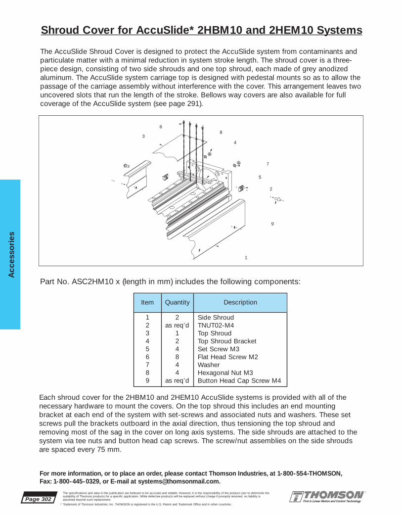
Page 302The specifications and data in this publication are believed to be accurate and reliable. However, it is the responsibility of the product user to determine thesuitability of Thomson products for a specific application. While defective products will be replaced without charge if promptly returned, no liability isassumed beyond such replacement.
* Trademark of Thomson Industries, Inc. THOMSON is registered in the U.S. Patent and Trademark Office and in other countries.
Acc
esso
ries
For more information, or to place an order, please contact Thomson Industries, at 1-800-554-THOMSON, Fax: 1-800-445-0329, or E-mail at [email protected].
Shroud Cover for AccuSlide* 2HBM10 and 2HEM10 Systems
The AccuSlide Shroud Cover is designed to protect the AccuSlide system from contaminants andparticulate matter with a minimal reduction in system stroke length. The shroud cover is a three-piece design, consisting of two side shrouds and one top shroud, each made of grey anodized aluminum. The AccuSlide system carriage top is designed with pedestal mounts so as to allow thepassage of the carriage assembly without interference with the cover. This arrangement leaves twouncovered slots that run the length of the stroke. Bellows way covers are also available for full coverage of the AccuSlide system (see page 291).
1
34
5
6
7
8
2
9
Item
123456789
2as req’d
124844
as req’d
Side ShroudTNUT02-M4Top ShroudTop Shroud BracketSet Screw M3Flat Head Screw M2WasherHexagonal Nut M3Button Head Cap Screw M4
Quantity Description
Each shroud cover for the 2HBM10 and 2HEM10 AccuSlide systems is provided with all of thenecessary hardware to mount the covers. On the top shroud this includes an end mounting bracket at each end of the system with set-screws and associated nuts and washers. These setscrews pull the brackets outboard in the axial direction, thus tensioning the top shroud and removing most of the sag in the cover on long axis systems. The side shrouds are attached to thesystem via tee nuts and button head cap screws. The screw/nut assemblies on the side shroudsare spaced every 75 mm.
Part No. ASC2HM10 x (length in mm) includes the following components:

The specifications and data in this publication are believed to be accurate and reliable. However, it is the responsibility of the product user to determine thesuitability of Thomson products for a specific application. While defective products will be replaced without charge if promptly returned, no liability isassumed beyond such replacement.
* Trademark of Thomson Industries, Inc. THOMSON is registered in the U.S. Patent and Trademark Office and in other countries.
Accesso
ries
Page 303
For more information, or to place an order, please contact Thomson Industries, at 1-800-554-THOMSON, Fax: 1-800-445-0329, or E-mail at [email protected].
Shroud Cover for AccuSlide* 2HBM20 and 2HEM20 Systems
The AccuSlide Shroud Cover is designed to protect the AccuSlide system from contaminants andparticulate matter with a minimal reduction in system stroke length. The shroud cover is a three-piece design, consisting of two side shrouds and one top shroud, each made of grey anodized alu-minum. The AccuSlide system carriage top is designed with pedestal mounts so as to allow thepassage of the carriage assembly without interference with the cover. This arrangement leaves twouncovered slots that run the length of the stroke. Bellows way covers are also available for full coverage of the AccuSlide system (see page 291).
1
3
4
6
7
82
9
5
Item
123456789
2as req’d
124844
as req’d
Side ShroudTNUT04-M6Top ShroudTop Shroud BracketSet Screw M4Flat Head Screw M3WasherHexagonal Nut M4Button Head Cap Screw M6
Quantity Description
Each shroud cover for the 2HBM20 and 2HEM20 AccuSlide systems is provided with all of thenecessary hardware to mount the covers. On the top shroud this includes an end mounting bracket at each end of the system with set-screws and associated nuts and washers. These setscrews pull the brackets outboard in the axial direction, thus tensioning the top shroud and removing most of the sag in the cover on long axis systems. The side shrouds are attached to thesystem via tee nuts and button head cap screws. The screw/nut assemblies on the side shroudsare spaced every 120 mm.
Part No. ASC2HM20 x (length in mm) includes the following components:

Page 304The specifications and data in this publication are believed to be accurate and reliable. However, it is the responsibility of the product user to determine thesuitability of Thomson products for a specific application. While defective products will be replaced without charge if promptly returned, no liability isassumed beyond such replacement.
* Trademark of Thomson Industries, Inc. THOMSON is registered in the U.S. Patent and Trademark Office and in other countries.
Acc
esso
ries
For more information, or to place an order, please contact Thomson Industries, at 1-800-554-THOMSON, Fax: 1-800-445-0329, or E-mail at [email protected].
TEB Spring Set Electric BrakesFor use on Ball Screw Assembly, SuperSlide and PowerSlide Linear Motion Systems
Electric Brake:• Mounts to support end of all
SuperSlide*, PowerSlide* and BallScrew assembly systems
• Engages upon loss of a 24-VDC PowerSupply (see TBC-7 data on page 306)
• Provides resistance to back drive rotation of ball screws due to gravitational force when power is interrupted to the brake unit
• Pre-burnished for maximum torquecapacity
• Standard NEMA 23, 34 and 42mounting patterns for easy field retrofit
• Compact size minimizes changeto overall system envelope
• Easily integrates with TBC-7 BrakeController to offer a completebraking solution, see page 306
For immediate Application Engineering Assistance contact the Thomson Toll Free Helpline*:
= 800-554-THOMSON (800-554-8466)

The specifications and data in this publication are believed to be accurate and reliable. However, it is the responsibility of the product user to determine thesuitability of Thomson products for a specific application. While defective products will be replaced without charge if promptly returned, no liability isassumed beyond such replacement.
* Trademark of Thomson Industries, Inc. THOMSON is registered in the U.S. Patent and Trademark Office and in other countries.
Accesso
ries
Page 305
For more information, or to place an order, please contact Thomson Industries, at 1-800-554-THOMSON, Fax: 1-800-445-0329, or E-mail at [email protected].
Thomson Spring Set Electric Brakes
.625HEX
12 ± 1⁄2
H
Ø F
GMAX.
J (SQ.)
4X Ø K EQ. SP.
ON A Ø L B.C.
A
C
D
D
Ø B E
120º
NOTE 1: Suggested torque for hub set screws are 36 in-lb for #10-32, M4, M5, and 87 in-lb for 1/4-20. Additionally, it is suggested a serviceable thread locking compound be used.
Brake Hub Data
90º D
D
Splined Hub Part No. SPLHUB42AFor Brake Part No. TEB-42A
Hex-Hubs for all NEMA 23 and 34 Size Brakes
*All brakes require 24 VDC
Spring Set Brake Data
Brake HubPart No.
Dimensions
HEXHUB23AHEXHUB23BHEXHUB23CHEXHUB23DHEXHUB23EHEXHUB23FHEXHUB34AHEXHUB34BHEXHUB34CHEXHUB34DSPLHUB42A
A
1.53 in.1.31 in.1.67 in.20 mm20 mm
15.6 mm1.67 in.0.82 in.32 mm22 mm1.66 in.
3/16 in.1/4 in.3/8 in.8 mm10 mm12 mm3/8 in.1/2 in.14 mm15 mm5/8 in.
0.15 in.0.26 in.0.44 in.5 mm5 mm
10.8 mm0.44 in.0.21 in.6 mm6 mm
0.50 in.
#10-32#10-32#10-32.
M4M4M4
#10-32#10-32
M5M5
1/4 20
B C D(1)
5/8 in.5/8 in.5/8 in.5/8 in.5/8 in.7/8 in.5/8 in.7/8 in.7/8 in.7/8 in.
-
EUsed with System
Part NumberUsed with
Spring Set Brake
2DB082AB08, 2CB08, 2CB12, 2DB12, 2EB08, BSA08, BSDAM122AB12, 2EB12, BSA12, BSAM202HBM10, 2RBM122NBM20, 2RBM162HEM10, 2NEM20, 2REM12, 2REM162DB16, 2CB162AB16, 2EB16, BSA162HBM202HEM202AB24, 2EB24, BSA24
Electric BrakePart No.
Brake Adaptor Part No
Brake Hub Part No
Dimensions (in.)
HEXHUB23AHEXHUB23BHEXHUB23CHEXHUB23DHEXHUB23EHEXHUB23FHEXHUB34AHEXHUB34BHEXHUB34CHEXHUB34DSPLHUB42A
MB08-23None RequiredNone RequiredNone RequiredNone RequiredEBA23FNone RequiredNone RequiredNone RequiredEBA34DNone Required
TEB23ATEB23BTEB23CTEB23DTEB23ETEB23FTEB34ATEB34BTEB34CTEB34DTEB42A
Frame Size
NEMA 23NEMA 23NEMA 23NEMA 23NEMA 23NEMA 23NEMA 34NEMA 34NEMA 34NEMA 34NEMA 42
StaticTorque (lbf-in.)
NEMA 23NEMA 23NEMA 23NEMA 23NEMA 23NEMA 23NEMA 34NEMA 34NEMA 34NEMA 34NEMA 42
F
2.252.252.252.252.252.252.252.252.252.254.19
1.101.101.101.101.101.101.101.311.311.312.38
0.110.110.110.110.110.110.110.110.110.110.36
2.252.252.252.252.252.253.253.253.253.254.25
G H J
0.220.220.220.220.220.220.220.220.220.220.27
K
2.6252.6252.6252.6252.6252.6253.8753.8753.8753.8754.950
L
5/85/85/85/85/87/85/87/87/87/8
Splined
HEXUsed with System
Part Number
2DB082AB08, 2CB08, 2CB12, 2DB12, 2EB08, BSA08, BSDAM122AB12, 2EB12, BSA12, BSAM202HBM10, 2RBM122NBM20, 2RBM162HEM10, 2NEM20, 2REM12, 2REM162DB16, 2CB162AB16, 2EB16, BSA162HBM202HEM202AB24, 2EB24, BSA24
TEB23ATEB23BTEB23CTEB23DTEB23ETEB23FTEB34ATEB34BTEB34CTEB34DTEB42A

Page 306The specifications and data in this publication are believed to be accurate and reliable. However, it is the responsibility of the product user to determine thesuitability of Thomson products for a specific application. While defective products will be replaced without charge if promptly returned, no liability isassumed beyond such replacement.
* Trademark of Thomson Industries, Inc. THOMSON is registered in the U.S. Patent and Trademark Office and in other countries.
Acc
esso
ries
For more information, or to place an order, please contact Thomson Industries, at 1-800-554-THOMSON, Fax: 1-800-445-0329, or E-mail at [email protected].
TBC-7 ELECTRIC BRAKE CONTROLLER
Features:
• Operates Thomson’s TEB series electric brakes orany 24 VDC spring set brake, 1 amp max
• Optical isolated control input
• Direct connection to any PLC, switch, relay, or computer, or CNC output.
• Black textured ABS enclosure with mounting feet, U.L. 94VO rated
• Overexcite spiking dramatically reduces brakeresponse time
• Underexcite feature for cooler operating brake
• 115/220 VAC 50/60 Hz input, switch selectable
• Fused for protection
• Solid state design for highest reliability
The TBC-7 Brake Control/Power Supply is designed to operate most 24 VDC rated brakes.Flexible control inputs allow the brake to be switched on and off in a variety of ways:
- a 3 to 28 volt DC signal- any dry contact switch or relay- function as a simple power supply, switching the brake on and off with input power.
This flexibility allows the TBC-7 to interface directly to almost any PLC, switch, relay, computer,CNC, or motion controller output.
Incorporating the latest in MOSFET switching technology, the TBC-7 features overexcite/underexcite operation. Overexcite operation applies a high voltage spike to decrease the brake’sresponse time, while underexcite operation reduces the brake’s average operating current makingfor a much cooler running brake. The TBC-7 may be powered by 115 VAC or 220 VAC, and isswitch selectable. In addition, it has an optically isolated control input which completely eliminatesnoise feedback into the control system.
Electrical Specifications:Input Power: 115/220VAC switch selectable
50/60 Hz single phase1 amp maximum
Output Power: Underexcite/overexcite sequence suitable for any 24VDC brake rated up to 1.0 amp
Overexcite: 36VDC nominal for 200msUnderexcite: 18VDC after overexcite completeControl Interface: H11AA1 type optoisolator for voltage source switching or
internal pullup to own supply for dry contact switching

The specifications and data in this publication are believed to be accurate and reliable. However, it is the responsibility of the product user to determine thesuitability of Thomson products for a specific application. While defective products will be replaced without charge if promptly returned, no liability isassumed beyond such replacement.
* Trademark of Thomson Industries, Inc. THOMSON is registered in the U.S. Patent and Trademark Office and in other countries.
Accesso
ries
Page 307
For more information, or to place an order, please contact Thomson Industries, at 1-800-554-THOMSON, Fax: 1-800-445-0329, or E-mail at [email protected].
.125(3,2) .500
(12,7)
.187 (4,8)thru
3.350(85,1)
2.524(64,1)
4.588(116,5)
C/L
1.330(33,8)
1.675(42,6)
TBC-7 Dimensions
ACPower
ControlInterface
BrakeCoil
n Line 1n Line 2n Gnd
Brake nGnd nBrake n
InputVoltageSelector
n 115n 220
3-28 V Input nSwitch Input nSwitch Input n3-28 V Input n
GNDBrake
Brake
24 VDCBrake coil
115/220 vac
3-28 voltsswitch or relay
NOTE: choose EITHER switch orvoltage source operation.
TBC-7 Wiring Diagram

TNUT-01-M3TNUT-02-M4TNUT-03-M4TNUT-03-M5TNUT-04-M4TNUT-04-M5TNUT-04-M6TNUT-05-M4TNUT-05-M5TNUT-05-M6TNUT-05-M8
2RxM12, 2HxM10, 2HxM202NxM20, 2RxM16, 2HxM102RxM122RxM122NxM20, 2RxM16, 2HxM20,2GEM25
2GEM35
Page 308The specifications and data in this publication are believed to be accurate and reliable. However, it is the responsibility of the product user to determine thesuitability of Thomson products for a specific application. While defective products will be replaced without charge if promptly returned, no liability isassumed beyond such replacement.
* Trademark of Thomson Industries, Inc. THOMSON is registered in the U.S. Patent and Trademark Office and in other countries.
Acc
esso
ries
For more information, or to place an order, please contact Thomson Industries, at 1-800-554-THOMSON, Fax: 1-800-445-0329, or E-mail at [email protected].
Handwheels for Manual Actuation of SuperSlide* Systems
T-Nuts for Mounting
B
EC
D
F
A
45o
Part No. O.D. Thru Hole Handle
HW4R-188HW4R-250HW4R-375HW4R-500HW4R-625HW4R-M8HW4R-M10HW4R-M14HW4R-747
4.0 inch4.0 inch4.0 inch4.0 inch4.0 inch4.0 inch4.0 inch4.0 inch4.0 inch
0.188 in0.250 in0.375 in0.500 in0.625 in8 mm10 mm14 mm0.747 in
RevolvingRevolvingRevolvingRevolvingRevolvingRevolvingRevolvingRevolvingRevolving
Part No. O.D. Thru Hole Handle
HW5R-188HW5R-250HW5R-375HW5R-500HW5R-625HW5R-M8HW5R-M10HW5R-M14HW5R-747
5.0 inch5.0 inch5.0 inch5.0 inch5.0 inch5.0 inch5.0 inch5.0 inch5.0 inch
0.188 in0.250 in0.375 in0.500 in0.625 in8 mm10 mm14 mm0.747 in
RevolvingRevolvingRevolvingRevolvingRevolvingRevolvingRevolvingRevolvingRevolving
Part No. O.D. Thru Hole Handle
HW5F-188HW5F-250HW5F-375HW5F-500HW5F-625HW5F-M8HW5F-M10HW5F-M14HW5F-747
5.0 inch5.0 inch5.0 inch5.0 inch5.0 inch5.0 inch5.0 inch5.0 inch5.0 inch
0.188 in0.250 in0.375 in0.500 in0.625 in8 mm10 mm14 mm0.747 in
FoldingFoldingFoldingFoldingFoldingFoldingFoldingFoldingFolding
Part No. O.D. Thru Hole Handle
HW4F-188HW4F-250HW4F-375HW4F-500HW4F-625HW4F-M8HW4F-M10HW4F-M14HW4F-747
4.0 inch4.0 inch4.0 inch4.0 inch4.0 inch4.0 inch4.0 inch4.0 inch4.0 inch
0.188 in0.250 in0.375 in0.500 in0.625 in8 mm10 mm14 mm0.747 in
FoldingFoldingFoldingFoldingFoldingFoldingFoldingFoldingFolding
Standard T-Nut Dimensions (Dimensions in mm)
Part NumberDimensions
A
79,51212
16,5
19,5
45,577
7,9
9,8
1,752,252,52,54,8
5,8
1,251,752,52,51,2
2,8
B C D
34556
8,6
E
M3M4M4M5M4M5M6M4M5M6M8
FUsed in conjunction with Systems
OD
TAPPED HOLE FOR SET SCREW
THRU HOLE SIZE
R = REVOLVINGF = FOLDING

ENGINEERINGSUPPORTENGINEERINGSUPPORT
www.thomsonindustries.com
SYSTEM SIZING CALCULATIONS FOR:• Inch size SuperSlide* ball screw actuated systems• Metric size SuperSlide ball screw actuated systems• Metric size SuperSlide belt actuated systems• Turbo Module* belt actuated systems
THOMSON INDUSTRIES, INC.
Engineering Guide for Systems, Slides & Stages, and Motion Control
For Application Engineering assistance contact the Thomson Technical HelpLine at 1-800-554-8466.* *Trademark of Thomson Industries, Inc. THOMSON is registered in the U.S. Patent and Trademark Office and in other countries. Page 309
System
s Eng
ineering S
upp
ort

Page 310The specifications and data in this publication are believed to be accurate and reliable. However, it is the responsibility of the product user to determine thesuitability of Thomson products for a specific application. While defective products will be replaced without charge if promptly returned, no liability is assumed beyond such replacement.
* Trademark of Thomson Industries, Inc. THOMSON is registered in the U.S. Patent and Trademark Office and in other countries.
Eng
inee
ring
Sup
po
rt -
Inc
h
INCHSuperSlide* Ball Screw Actuated SystemSystem Selection
Mounting Surfaces
End Support Block End Support Block
To determine the system that fits your SuperSlide Ball Screw Actuated System application requirements the following design criteria needs to be evaluated:
• System Support Requirements • Load/Life Requirements – Ball Screws• System Stroke Length • Motion (Move) Profile (Velocity, Acceleration)• Maximum Allowable Shaft Deflection • Maximum Acceptable Travel Rate• Required Travel Life • Maximum Compressive (Column) Load• Force on the Most Heavily Loaded Bearing • Torque Calculations• Load Correction Factor • Size Motor Using Torque/Speed Curves• Load/Life Requirements – Linear Bearings
After each criteria is determined, system selection will become quick and easy. The following procedurewill guide you through the proper system selection.
Step 1. Based on your application needs determine the mounting support requirements.
Mounting Surface
SuperSlide 2CBEnd Supported System
SuperSlide Ball Screw Actuated System 2AB, 2BB and 2CB are designed to quickly mount over a gap asshown in the above illustration. For other mountingideas contact Thomson Systems application engineering.
SuperSlide Ball Screw Actuated System 2DB and 2EBare designed to be mounted continuously over a surfacefor reduced deflection as shown in the above illustration.For other mounting ideas contact Thomson Systems application engineering.
SuperSlide 2DBContinuously Supported System
For more information, or to place an order, please contact Thomson Industries, at 1-800-554-THOMSON, Fax: 1-800-445-0329, or E-mail at [email protected].

The specifications and data in this publication are believed to be accurate and reliable. However, it is the responsibility of the product user to determine thesuitability of Thomson products for a specific application. While defective products will be replaced without charge if promptly returned, no liability is assumed beyond such replacement.
* Trademark of Thomson Industries, Inc. THOMSON is registered in the U.S. Patent and Trademark Office and in other countries.
Eng
ineering S
upp
ort - Inch
Page 311
System 12 16 18 20 24 28 30 32 36 40 42 44 48 54 60 72 X MAX2DB-08 ■ ■ ■ ■ ■ ■ ■ ■ ■ ■ 4 482DB-12 ■ ■ ■ ■ ■ ■ 6 722DB-16 ■ ■ ■ ■ ■ ■ ■ ■ ■6 96
L
L3
H3
T1
Custom Lengths and Delivery InformationSystems ordered in standard lengths and longerlengths in increments of (X) are typically shipped intwo to three weeks. Custom length systems are available and require three to four weeks for delivery.Lengths exceeding MAX length will require butt jointsand will need 4 to 6 weeks for delivery. For specialrequirements, please contact the Thomson Systemsapplication engineering department.
Step 2. Determine the Stroke Length (LS) required. The maximum Stroke Length (LS) is determined bysubtracting the carriage length (T1) and twice end block lengths (L3) from the total system length (L). The application or required stroke length should not exceed this number.
LS = L - (T1 + 2 L3)
INCHSuperSlide* Ball Screw Actuated SystemSystem Stroke Length
SuperSlide System 2DB Standard Lengths (Lengths in inches)
Should your application require the use of bellows way covers, it is important to recognize that the bellows will detract from the available stroke of the system. The bellows will retract to approximately14% of the available stroke at each end of the system. The stroke length with bellows (LS/B) iscalculated by subtracting 2 times the stroke (LS) times .14 from the stroke (LS).
LS/B = LS - (2 x LS x .14)
Standard Length and Delivery. For each SuperSlide Ball Screw Actuated System there is a standardlength chart and delivery information that also includes the standard length increment and the maximum system length. Selecting a standard system length will minimize shipment time. Once youhave selected a length that best fits your application requirements, simply determine the maximumstroke length. The required stroke length should not exceed this number. Refer to the product specification section for the standard length charts not shown.
For more information, or to place an order, please contact Thomson Industries, at 1-800-554-THOMSON, Fax: 1-800-445-0329, or E-mail at [email protected].

Page 312The specifications and data in this publication are believed to be accurate and reliable. However, it is the responsibility of the product user to determine thesuitability of Thomson products for a specific application. While defective products will be replaced without charge if promptly returned, no liability is assumed beyond such replacement.
* Trademark of Thomson Industries, Inc. THOMSON is registered in the U.S. Patent and Trademark Office and in other countries.
Eng
inee
ring
Sup
po
rt -
Inc
h
Step 3. Determine if the system selected meets the Maximum Allowable Deflection criteria.
Step 4. Determine the Required Application Travel Life (in).
Lt = required travel life (in)Lt= 2 • s • f • Lh • 60 s = stroke (in)
f = frequency (cycles/minute)Lh= service life (hrs)
10 000
5 000
2 000
1 000
500
200
100
50
20
106 12 18 24 30 36 42 48 54 60 66 72
Maximum Recommended Load on System
System Length (in)
Load
on
Sys
tem
(lb
f) 2AB-24
2AB-16
2AB-12
2AB-08
In end supported applications the bearing system canwithstand an enormous amount of system deflectionand still run smoothly due to the universal self-aligningfeature of the Super Smart Ball Bushing* bearing. In aball screw actuated end supported application, deflection is limited by the small amount of radial loadthat a ball screw assembly can withstand. Step 3 willdetermine if the system size and length can handle theapplied load. For SuperSlide Ball Screw ActuatedSystem 2AB there is a graph (SBSU 5.1) that gives themaximum recommended load on the system based onshaft and ball screw deflection. To determine the system that best meets your application requirements,simply enter the graph with the total load on the system and the overall system length. Select a systemcharacteristic curve that is above or to the right of theplotted point. To determine the actual deflection seethe Engineering Support Appendix, page 378.
INCHSuperSlide* Ball Screw Actuated SystemEnd Supported System Maximum Allowable Deflection
2BB 2CB2AB
Graph (SBSU 5.1)
Travel Life
For more information, or to place an order, please contact Thomson Industries, at 1-800-554-THOMSON, Fax: 1-800-445-0329, or E-mail at [email protected].
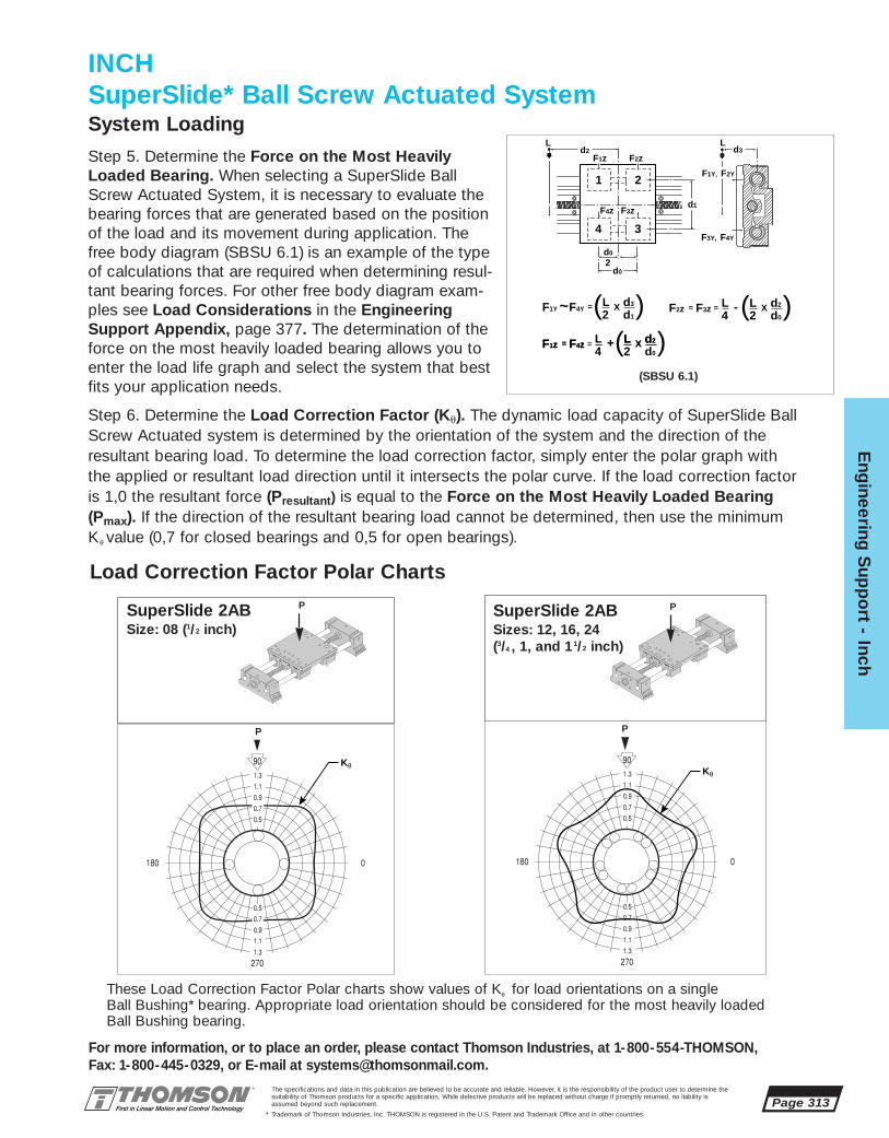
The specifications and data in this publication are believed to be accurate and reliable. However, it is the responsibility of the product user to determine thesuitability of Thomson products for a specific application. While defective products will be replaced without charge if promptly returned, no liability is assumed beyond such replacement.
* Trademark of Thomson Industries, Inc. THOMSON is registered in the U.S. Patent and Trademark Office and in other countries.
Eng
ineering S
upp
ort - Inch
Page 313
Step 6. Determine the Load Correction Factor (Ku). The dynamic load capacity of SuperSlide BallScrew Actuated system is determined by the orientation of the system and the direction of theresultant bearing load. To determine the load correction factor, simply enter the polar graph withthe applied or resultant load direction until it intersects the polar curve. If the load correction factoris 1,0 the resultant force (Presultant) is equal to the Force on the Most Heavily Loaded Bearing(Pmax). If the direction of the resultant bearing load cannot be determined, then use the minimumKu value (0,7 for closed bearings and 0,5 for open bearings).
Step 5. Determine the Force on the Most HeavilyLoaded Bearing. When selecting a SuperSlide BallScrew Actuated System, it is necessary to evaluate thebearing forces that are generated based on the positionof the load and its movement during application. Thefree body diagram (SBSU 6.1) is an example of the typeof calculations that are required when determining resul-tant bearing forces. For other free body diagram exam-ples see Load Considerations in the EngineeringSupport Appendix, page 377. The determination of theforce on the most heavily loaded bearing allows you toenter the load life graph and select the system that bestfits your application needs.
INCHSuperSlide* Ball Screw Actuated SystemSystem Loading
1 2
34
L L
2
d2
d0
d0
d3
d1
F1z F2z
F4z F3z
F3Y, F4Y
F1Y, F2Y
F1Y F4YL2
d3
d1~ =( (X
F1z F4z L2
L4
d2
d0= ( X+F1z F4z L d2== (X+
24 d0F2z F3z LL d2== ( (X-
(SBSU 6.1)
Kθ
P
Kθ
SuperSlide 2ABSize: 08 (1/2 inch)
P
Load Correction Factor Polar Charts
P P
SuperSlide 2ABSizes: 12, 16, 24 (3/4 , 1, and 11/2 inch)
These Load Correction Factor Polar charts show values of Ku for load orientations on a single Ball Bushing* bearing. Appropriate load orientation should be considered for the most heavily loadedBall Bushing bearing.
For more information, or to place an order, please contact Thomson Industries, at 1-800-554-THOMSON, Fax: 1-800-445-0329, or E-mail at [email protected].

Page 314The specifications and data in this publication are believed to be accurate and reliable. However, it is the responsibility of the product user to determine thesuitability of Thomson products for a specific application. While defective products will be replaced without charge if promptly returned, no liability is assumed beyond such replacement.
* Trademark of Thomson Industries, Inc. THOMSON is registered in the U.S. Patent and Trademark Office and in other countries.
Eng
inee
ring
Sup
po
rt -
Inc
h
INCHSuperSlide* Ball Screw Actuated SystemLoad Correction Factor Polar Charts
Kθ
SuperSlide 2CBSizes: 12, 16 (3/4 and 1 inch)
P
Kθ
SuperSlide 2CBSize: 08 (1/2 inch)
P
P P
Kθ
SuperSlide 2DBSizes: 12, 16(3/4 and 1 inch)
P
P
Kθ
SuperSlide 2DBSize: 08 (1/2 inch)
P
P
These Load Correction Factor Polar charts show values of Ku for load orientations on a single Ball Bushing* bearing. Appropriate load orientation should be considered for the most heavilyloaded Ball Bushing bearing.
For more information, or to place an order, please contact Thomson Industries, at 1-800-554-THOMSON, Fax: 1-800-445-0329, or E-mail at [email protected].

The specifications and data in this publication are believed to be accurate and reliable. However, it is the responsibility of the product user to determine thesuitability of Thomson products for a specific application. While defective products will be replaced without charge if promptly returned, no liability is assumed beyond such replacement.
* Trademark of Thomson Industries, Inc. THOMSON is registered in the U.S. Patent and Trademark Office and in other countries.
Eng
ineering S
upp
ort - Inch
Page 315
For more information, or to place an order, please contact Thomson Industries, at 1-800-554-THOMSON, Fax: 1-800-445-0329, or E-mail at [email protected].
If the Load Correction Factor is less than 1.0 the following formula should be used to determine theCorrected Force on the Most Heavily Loaded Bearing.
Pmax = Force on the Most Heavily Loaded Bearing (N)Pmax = Presultant Presultant = Resultant of Externally Applied loads (N)
Ku Ku = Load Correction Factor
Kθ
SuperSlide 2EBSizes: 12, 16, 24 (3/4 , 1, and 11/2 inch)
P
P
Kθ
SuperSlide 2EBSize: 08 (1/2 inch)
P
P
INCHSuperSlide* Ball Screw Actuated SystemLoad Correction Factor Polar Charts
These Load Correction Factor Polar charts show values of Ku for load orientations on a single Ball Bushing* bearing. Appropriate load orientation should be considered for the most heavilyloaded Ball Bushing bearing.
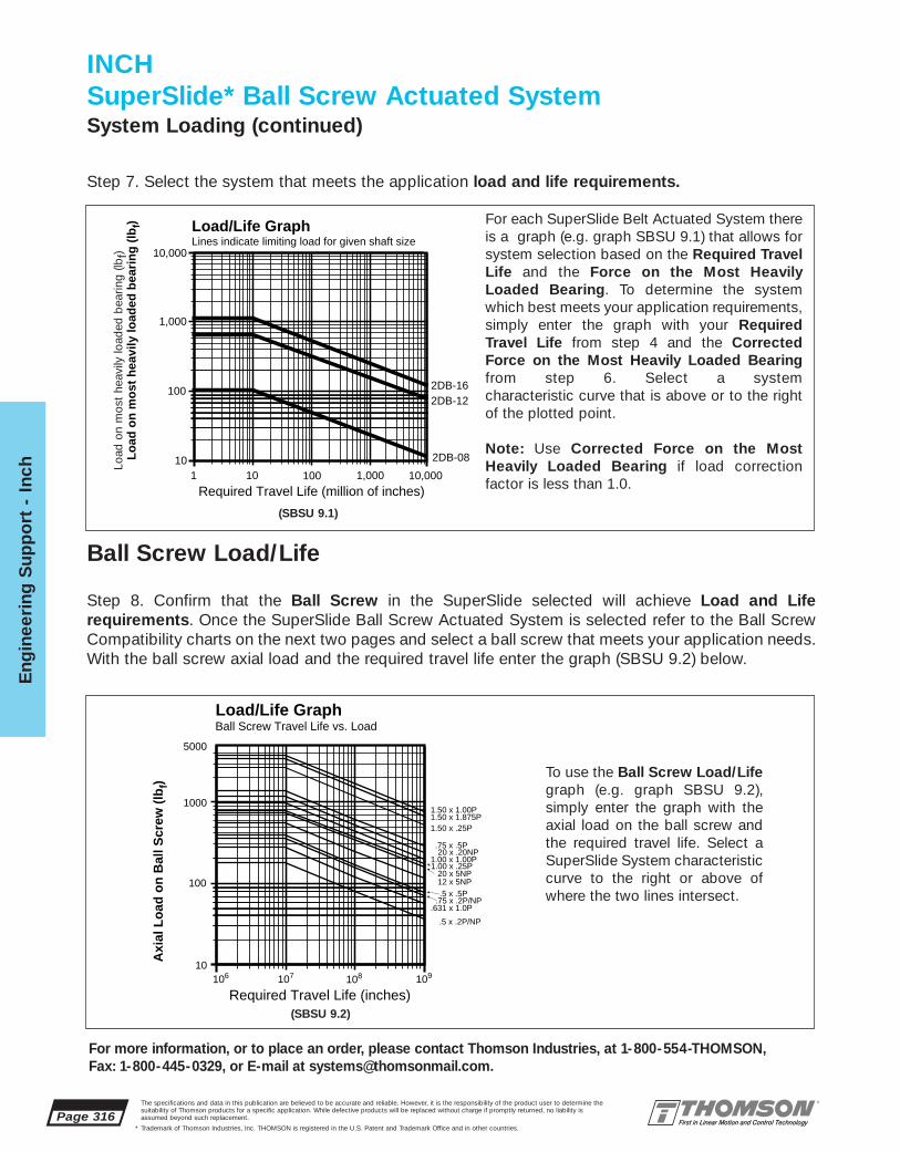
Load/Life GraphLines indicate limiting load for given shaft size
Lo
ad o
n m
ost
hea
vily
load
ed b
eari
ng
(lb
f)
110
10
100
100
1,000
1,000
10,000
10,000
Required Travel Life (million of inches)
2DB-08
2DB-162DB-12
Page 316The specifications and data in this publication are believed to be accurate and reliable. However, it is the responsibility of the product user to determine thesuitability of Thomson products for a specific application. While defective products will be replaced without charge if promptly returned, no liability is assumed beyond such replacement.
* Trademark of Thomson Industries, Inc. THOMSON is registered in the U.S. Patent and Trademark Office and in other countries.
Eng
inee
ring
Sup
po
rt -
Inc
h
For each SuperSlide Belt Actuated System thereis a graph (e.g. graph SBSU 9.1) that allows forsystem selection based on the Required TravelLife and the Force on the Most HeavilyLoaded Bearing. To determine the systemwhich best meets your application requirements,simply enter the graph with your RequiredTravel Life from step 4 and the CorrectedForce on the Most Heavily Loaded Bearingfrom step 6. Select a system characteristic curve that is above or to the rightof the plotted point.
Note: Use Corrected Force on the MostHeavily Loaded Bearing if load correction factor is less than 1.0.
Step 7. Select the system that meets the application load and life requirements.
(SBSU 9.1)
Step 8. Confirm that the Ball Screw in the SuperSlide selected will achieve Load and Life requirements. Once the SuperSlide Ball Screw Actuated System is selected refer to the Ball ScrewCompatibility charts on the next two pages and select a ball screw that meets your application needs.With the ball screw axial load and the required travel life enter the graph (SBSU 9.2) below.
Load/Life GraphBall Screw Travel Life vs. Load
Axi
al L
oad
on
Bal
l Scr
ew (
lbf)
Required Travel Life (inches)
1.00 x 1.00P1.00 x .25P
20 x .20NP
20 x 5NP
1.50 x 1.875P1.50 x 1.00P
1.50 x .25P
12 x 5NP
.5 x .2P/NP
.5 x .5P
.631 x 1.0P.75 x .2P/NP
.75 x .5P
106 10710
108
100
109
1000
5000
To use the Ball Screw Load/Lifegraph (e.g. graph SBSU 9.2), simply enter the graph with theaxial load on the ball screw andthe required travel life. Select aSuperSlide System characteristiccurve to the right or above ofwhere the two lines intersect.
Ball Screw Load/Life
(SBSU 9.2)
INCHSuperSlide* Ball Screw Actuated SystemSystem Loading (continued)
For more information, or to place an order, please contact Thomson Industries, at 1-800-554-THOMSON, Fax: 1-800-445-0329, or E-mail at [email protected].
Load
on
mos
t he
avily
load
ed b
earin
g (lb
f)

The specifications and data in this publication are believed to be accurate and reliable. However, it is the responsibility of the product user to determine thesuitability of Thomson products for a specific application. While defective products will be replaced without charge if promptly returned, no liability is assumed beyond such replacement.
* Trademark of Thomson Industries, Inc. THOMSON is registered in the U.S. Patent and Trademark Office and in other countries.
Eng
ineering S
upp
ort - Inch
Page 317
P-Preloaded
NP- Non-Preloaded
Part Number
2DB-08
2DB-12
2DB-16
P-Preloaded
NP- Non-Preloaded
P-Preloaded
NP- Non-Preloaded
Part Number
2AB-08
2AB-12
2AB-16
2AB-24
For more information, or to place an order, please contact Thomson Industries, at 1-800-554-THOMSON, Fax: 1-800-445-0329, or E-mail at [email protected].
SuperSlide 2DBContinuously Supported System
INCHSuperSlide* Ball Screw Actuated SystemBall Screw and System Compatibility
SuperSlide 2DB Ball Screw and Screw Actuator Compatibility Chart
.375 x .1 .375 x .25 .375 x .50 .375 x .75 .375 x 1.0 .50 x .20 .50 x .20 .50 x .50 .631 x 1.0 .75 x .20 .75 x .20 .75 x.50 12 x 5 20 x 5
P P P P P P NP P P P NP P NP NP
■ ■ ■ ■ ■
■ ■ ■ ■
■ ■ ■ ■ ■
Lead Screw or Ball Screw Diameter and Lead Metric
SuperSlide 2BB/2CB Lead Screw or Ball Screw Actuator Compatibility Chart
.375 x .10 .375 x .25 .375 x .50 .375 x .75 .375 x 1.0 .50 x .20 50 x .20 .75 x .20 .75 x .20 12 X 5 16 X 5 20 X 5
P P P P P NP P NP P NP NP NP
■ ■ ■ ■ ■
■ ■ ■
■
■ ■ ■
Lead Screw or Ball Screw Diameter and Lead Metric
SuperSlide 2BB/ 2CBEnd Supported System
SuperSlide 2ABEnd Supported System
SuperSlide 2AB Ball Screw Compatibility Chart
.50 x .20 .50 x .20 .50 x .50 .631 x 1.0 .75 x .20 .75 x .20 1.0 X .25 1.0 X 1.0 1.5 X .25 1.5 X 1.0 1.5 X 1.875 12 X 5 20 X 5 20 X 20
NP P P P NP P P P P P P NP NP NP
■ ■ ■ ■
■ ■ ■ ■ ■
■ ■
■ ■ ■
Ball Screw Diameter and Lead Metric
Part Number
2BB-06
2CB-08
2CB-12
2CB-16

Page 318The specifications and data in this publication are believed to be accurate and reliable. However, it is the responsibility of the product user to determine thesuitability of Thomson products for a specific application. While defective products will be replaced without charge if promptly returned, no liability is assumed beyond such replacement.
* Trademark of Thomson Industries, Inc. THOMSON is registered in the U.S. Patent and Trademark Office and in other countries.
Eng
inee
ring
Sup
po
rt -
Inc
h
P-Preloaded
NP- Non-Preloaded
Part Number
2EB-08
2EB-12
2EB-16
2EB-24
For more information, or to place an order, please contact Thomson Industries, at 1-800-554-THOMSON, Fax: 1-800-445-0329, or E-mail at [email protected].
INCHSuperSlide* Ball Screw Actuated SystemBall Screw and System Compatibility (continued)
SuperSlide 2EBContinuously Supported System
SuperSlide 2EB Ball Screw Compatibility Chart
.50 x .20 .50 x .20 .50 x .50 .631 x 1.0 .75 x .20 .75 x .20 1.0 X .25 1.0 X 1.0 1.5 X .25 1.5 X 1.0 1.5 X 1.875 12 X 5 20 X 5 20 X 20
NP P P P NP P P P P P P NP NP NP
■ ■ ■ ■
■ ■ ■ ■ ■
■ ■
■ ■ ■
Ball Screw Diameter and Lead Metric
Motion ProfileA typical linear ball screw actuated application normally consists of a series of motion profiles. The drivetorque required to move the system should be evaluated for each motion profile. There are two basic motionprofile types. The first and most simple move is a triangular motion profile which consists of two legs. Thefirst leg is for acceleration and the second is for deceleration. The second motion profile type is trapezoidalwhich consists of an acceleration leg; a leg of constant velocity and a deceleration leg.
Vmax Vmax
ta td
Accelerate(Time in seconds)
Decelerate(Time in seconds)
ta
Accelerate(Time in seconds)
td
Decelerate(Time in seconds)
tc
Constant Velocity(Time in seconds)
Velo
city
Velo
city
Triangular Motion Profile Trapezoidal Motion Profile
Step 9. Determine the Motion Profile that fits your application requirements. Calculate Vmax and a.
Trapezoidal Motion Profile:
Assume: ta = tc = td = t/3 and xa = xd = x/4, xc = x/2
Then: Vavg = x/tVmax = 1.5 • Vavg
a = -d = Vmax / ta = 4.5x/t2
t = Total Move Time (s)ta = Acceleration Time (s)tc = Time at Constant Velocity (s)td = Deceleration Time (s)
Vavg = Average Velocity (in/s)Vmax = Maximum Velocity (in/s)
Triangular Motion Profile:
Assume: ta = td = t/2 and xa = xd = x/2
Then: Vavg = x/tVmax = 2 • Vavg = 2x/t
a = Vmax / ta = 4 x/t2
Where: a = acceleration (in/s2)d = Deceleration (in/s2)x = Total Distance (in)
xa = Distance to Accelerate (in)xc = Distance at Constant Velocity (in)xd = Distance to Decelerate (in)

The specifications and data in this publication are believed to be accurate and reliable. However, it is the responsibility of the product user to determine thesuitability of Thomson products for a specific application. While defective products will be replaced without charge if promptly returned, no liability is assumed beyond such replacement.
* Trademark of Thomson Industries, Inc. THOMSON is registered in the U.S. Patent and Trademark Office and in other countries.
Eng
ineering S
upp
ort - Inch
Page 319
For more information, or to place an order, please contact Thomson Industries, at 1-800-554-THOMSON, Fax: 1-800-445-0329, or E-mail at [email protected].
Maximum AcceptableTravel Rate*
10010 20 30 40 60 100
System Length (in)*80% of Critical Speed
5000
1000
2000
200
500
Ro
tati
on
al S
pee
d (
rpm
)
200
20 x 5 NP
.5x .2 P/NP
.75 x 2 P/NP
12 x 5 NP
Each SuperSlide Ball Screw Actuated System has a Maximum Acceptable Travel Rate based onthe natural frequency of the whirling vibration of the ball screw. To determine the SuperSlidesystem that is capable of achieving the applications speeds, simply enter the graph with theMaximum Ball Screw Rotational Speed from step 10 and the required system length. Select theSuperSlide system characteristic curve to the right or above the plotted point.
Step 11. Confirm the system application Ball Screw Rotational Speed is below the MaximumAcceptable Travel Rate.
Maximum Acceptable Travel Rate
Step 10. Determine the Ball Screw and Motor Rotational Speed required to move at Vmax for the selected SuperSlide Ball Screw Actuated system.
SuperSlide Ball Screw Actuated Systems are equipped with a ball screw assembly already mounted. In Some SuperSlide sizes there are multiple ball screw leads available. To determine theavailability of ball screw leads for each superslide system see the Ball Screw Compatibility chartson page 317-318. To calculate the rotational speed (rpm) required to achieve Vmax, simply dividethe linear speed (in/s) by the corresponding ball screw lead (in/rev).
RPM = ( Vmax) x 60 sec/min P = Ball Screw Lead (in/rev)P Vmax = Maximum Linear Speed (in/s)
INCHSuperSlide* Ball Screw Actuated System

Page 320The specifications and data in this publication are believed to be accurate and reliable. However, it is the responsibility of the product user to determine thesuitability of Thomson products for a specific application. While defective products will be replaced without charge if promptly returned, no liability is assumed beyond such replacement.
* Trademark of Thomson Industries, Inc. THOMSON is registered in the U.S. Patent and Trademark Office and in other countries.
Eng
inee
ring
Sup
po
rt -
Inc
h
For more information, or to place an order, please contact Thomson Industries, at 1-800-554-THOMSON, Fax: 1-800-445-0329, or E-mail at [email protected].
INCHSuperSlide* Ball Screw Actuated SystemMaximum Compressive Load
Graph 13.2 is used to determine the Maximum Allowable Compressive Load for eachSuperSlide Ball Screw Actuated system. To determine the Maximum Allowable CompressiveLoad enter the graph with the Actual Compressive Load from (Graph 13.1) and intersect this linewith the system length. Select a system with a rated maximum Compressive Load characteristiccurve above or to the right of your plotted point.
Note: If the Actual Compressive Load is higher than the Maximum Allowable CompressiveLoad than the system size, length, load or acceleration should be reconsidered.
Graph SBSU 13.1 is used to determine the Actual Compressive Load on the system ball screwcaused by the load on the carriage and the system acceleration. To determine the ActualCompressive Load, enter the graph with the load on the carriage and intersect this line with thesystem acceleration and locate the compressive load on the ball screw.
Step 12. Determine if the application loads on the SuperSlide exceed the maximum compressive load limits of the ball screw. Determine the Actual Compressive Load and the Maximum AllowableCompressive Load.
Co
mp
ress
ive
Lo
ad o
n S
crew
(lb
f)
100 1000 1000010
1000
2000300040005000
100
200300400600
Load on Carriage (lbf)
Acceleration (ft/s2)
10
68
4
2
60
100 6080 40 30 20
40
20
10
20 x 5 NP
12 x 5 NP
.75 x .2 P/NP
.5 x .2 P/NP
1000
2000300040005000
100
200
400600
Co
mp
ressive Lo
ad o
n S
crew (lb
f)
System Length (in)
6040
20
10
10 20 30 40 60 100 200
Graph SBSU 13.2Graph SBSU 13.1
Actual Compressive Load Maximum Allowable Compressive Load

Step 13. In order to size a motor for your SuperSlide system it is important to calculate the torque required tomeet your application requirements with all of the parameters in mind. If you are actuating your system with a stepping motor, then a maximum or peak torque (Tpeak) calculation is required. Peak torque is usually seenat the time of maximum acceleration, however, other factors such as torque due to external forces can affectwhen peak torque occurs. It is important to calculate for all torque conditions (Torque due to acceleration(TA), Torque at constant velocity (Tcv), Torque due to deceleration (TD), and Torque required to hold atrest (TH)), and take that torque with the largest magnitude as the Peak Torque (Tpeak).
TA = TJ + TF + Tg + Te (oz • in)Tcv = TF + Tg + Te (oz • in)TD = TJ - TF - Tg - Te (oz • in)TH = -TF + Tg + Te (oz • in)
where: TJ = Torque due to system inertia (oz • in)TF = Torque due to friction (oz • in)Tg = Torque due to gravity (oz • in)Te = Torque due to external forces (oz • in)
Should you be actuating your SuperSlide system with a servo motor system then it is also necessary to calculate a Root-Mean-Square Torque (TRMS) or Continuous Torque.
TRMS = ta ( TA)2 + tcv (Tcv)2 + td (TD)2 + th (TH)2 ( oz • in)
ta + tcv + td + th
where: ta = time to accelerate (s)tcv = time at constant velocity (s)td = time to decelerate (s)th = time at rest (s)
Step 13a. Calculate Torque due to system inertia (TJ):
TJ = v JL + JB + JM (oz • in)g • ta jscrew
where: w = angular velocity (rad/s)JL = Load inertia (oz • in2)JB = Ball or Lead Screw inertia (oz • in2)JM = Motor inertia (oz • in2)(1) (1 oz • in2 = 386 oz • in • s2)ta = Time for acceleration (s) (from step 9)g = Acceleration due to gravity = 386 in/s2
jscrew = Efficiency of screw (from table on page 323)
(1) For motor inertia data see the Motion Control Section, page 431
Calculate Load inertia (JL):
JL = (Wc + Wp) P2 (oz • in2)
(2p)2
where: Wc = Weight of the Carriage (oz) (from table on next page)Wp = Weight of Payload (oz) (from Application Data)
P = Lead of Ball or Lead Screw (in/rev) (from table on page 323)p = 3.1416
The specifications and data in this publication are believed to be accurate and reliable. However, it is the responsibility of the product user to determine thesuitability of Thomson products for a specific application. While defective products will be replaced without charge if promptly returned, no liability is assumed beyond such replacement.
* Trademark of Thomson Industries, Inc. THOMSON is registered in the U.S. Patent and Trademark Office and in other countries.
Eng
ineering S
upp
ort - Inch
Page 321
INCHSuperSlide* Ball Screw Actuated SystemTorque Calculations
]]

Page 322The specifications and data in this publication are believed to be accurate and reliable. However, it is the responsibility of the product user to determine thesuitability of Thomson products for a specific application. While defective products will be replaced without charge if promptly returned, no liability is assumed beyond such replacement.
* Trademark of Thomson Industries, Inc. THOMSON is registered in the U.S. Patent and Trademark Office and in other countries.
Eng
inee
ring
Sup
po
rt -
Inc
h
For more information, or to place an order, please contact Thomson Industries, at 1-800-554-THOMSON, Fax: 1-800-445-0329, or E-mail at [email protected].
2EB-08 .50 30.4 .002 8 1.62EB-12 .75 76.8 .002 8 2.42EB-16 1.0 128.0 .002 8 4.82EB-24 1.5 403.2 .002 8 6.4
2DB-08-OUB .50 24.5 .002 4 1.62DB-12-OUB .75 63.5 .002 4 2.42DB-12-JUB .75 64.0 .002 8 2.42DB-16-OUB 1.0 120.5 .002 4 4.82DB-16-JUB 1.0 108.0 .002 8 4.8
2AB-08 .50 30.4 .002 8 1.62AB-12 .75 76.8 .002 8 2.42AB-16 1.0 128.0 .002 8 4.82AB-24 1.5 403.2 .002 8 6.4
Calculate Ball or Lead Screw inertia (Jb):
JB = p L r d4(oz • in2)
32
L = Length of Ball or Lead Screw (in)r = Density of Ball or Lead Screw = 4.48 oz/in3
d = Diameter of Ball or Lead Screw (in) (from table on next page)
Calulate angular velocity (v):
v = 2p Vmax (rad/S)P
where: Vmax = Maximum Linear Speed (in/s) (from step 9)P = Lead of Ball or Lead Screw (in/rev) (from table on next page)
SuperSlide 2EBSuperSlide 2DB
SuperSlide 2BB/2CBSuperSlide 2AB
Part Nominal Carriage Coefficient Number SealNumber Dia. Weight Friction of Drag
(oz) Carriage Seals (oz)
SuperSlide 2AB Ball Screw Actuated System DataPart Nominal Carriage Coefficient Number Seal
Number Dia. Weight Friction of Drag(oz) Carriage Seals (oz)
SuperSlide 2BB/2CB Lead Screw/Ball Screw Act. System Data
Part Nominal Carriage Coefficient Number SealNumber Dia. Weight Friction of Drag
(oz) Carriage Seals (oz)
SuperSlide 2DB Ball Screw Actuated System DataPart Nominal Carriage Coefficient Number Seal
Number Dia. Weight Friction of Drag(oz) Carriage Seals (oz)
SuperSlide 2EB Ball Screw Actuated System Data
2BB-06 .375 8.5 .002 0 —2CB-08 .50 20.3 .002 4 1.62CB-12 .75 48.0 .002 4 2.42CB-16 1.0 100.0 .002 4 4.8
INCHSuperslide* Ball Screw Actuated System

The specifications and data in this publication are believed to be accurate and reliable. However, it is the responsibility of the product user to determine thesuitability of Thomson products for a specific application. While defective products will be replaced without charge if promptly returned, no liability is assumed beyond such replacement.
* Trademark of Thomson Industries, Inc. THOMSON is registered in the U.S. Patent and Trademark Office and in other countries.
Eng
ineering S
upp
ort - Inch
Page 323
2EB-08-FTB-B .50 12 mm x 5 mm NP 6.4 0.902EB-08-FTB-F .50 .50 x .20 NP 6.4 0.902EB-08-FTB-Q .50 .50 x .50 P 7.2 0.902EB-12-FTB-D .75 20 mm x 5 mm NP 9.6 0.902EB-12-FTB-G .75 .75 x .20 NP 9.6 0.902EB-12-FTB-L .75 .631 x 1.0 P 7.2 0.902EB-12-FTB-U .75 20 mm x 20 mm NP 10.0 0.902EB-16-FTB-T 1.0 1.0 x 1.0 P 12.8 0.902EB-16-FTB-H 1.0 1.0 x .25 P 16.0 0.902EB-24-FTB-J 1.5 1.5 x 1.0 P 19.2 0.902EB-24-FTB-I 1.5 1.5 x .25 P 24.0 0.902EB-24-FTB-Z 1.5 1.5 x 1.875 P 16.0 0.90
2DB-08-OUB-AA .50 .375 x .1 P 3 to 6 0.532DB-08-OUB-AB .50 .375 x .25 P 3 to 6 0.602DB-08-OUB-AC .50 .375 x .50 P 3 to 6 0.812DB-08-OUB-AD .50 .375 x .75 P 3 to 6 0.842DB-08-OUB-AE .50 .375 x 1.0 P 3 to 6 0.842DB-12-OUB-B .75 12 mm x 5 mm NP 6.4 0.902DB-12-OUB-F .75 .50 x .20 NP 6.4 0.902DB-12-OUB-V .75 .50 x .20 P 9.6 0.902DB-12-JUB-Q .75 .50 x .50 P 7.2 0.902DB-16-OUB-D 1.0 20 mm x 5 mm NP 9.6 0.902DB-16-OUB-G 1.0 .75 x .20 NP 9.6 0.902DB-16-OUB-W 1.0 .75 x .20 P 12.4 0.902DB-16-OUB-L 1.0 .631 X 1.0 P 7.2 0.902DB-16-OUB-R 1.0 .75 X .50 P 8.4 0.90
2BB-06-OTH-AA .375 .375 x .1 P 3 to 6 0.532BB-06-OTH-AB .375 .375 x .25 P 3 to 6 0.602BB-06-OTH-AC .375 .375 x .50 P 3 to 6 0.812BB-06-OTH-AD .375 .375 x .75 P 3 to 6 0.842BB-06-OTH-AE .375 .375 x 1.0 P 3 to 6 0.842CB-08-OVA-B .75 12 mm x 5 mm NP 6.4 0.902CB-08-OVA-F .75 .50 x .20 NP 6.4 0.902CB-12-OVA-C 1.0 16 mm x 5 mm P 8.5 0.902CB-16-OVA-G 1.0 .75 x .20 NP 9.6 0.902CB-16-OVA-D 1.5 20 mm x 5 mm NP 9.6 0.90
2AB-08-ARB-B .50 12 mm x 5 mm NP 6.4 0.902AB-08-ARB-F .50 .50 x .20 NP 6.4 0.902AB-08-ARB-Q .50 .50 x .50 P 7.2 0.902AB-12-ARB-D .75 20 mm x 5 mm NP 9.6 0.902AB-12-ARB-G .75 .75 x .20 NP 9.6 0.902AB-12-ARB-L .75 .631 x 1.0 P 7.2 0.902AB-12-ARB-U .75 20 mm x 20 mm NP 10.0 0.902AB-16-ARB-T 1.0 1.0 x 1.0 P 12.8 0.902AB-16-ARB-H 1.0 1.0 x .25 P 16.0 0.902AB-24-ARB-J 1.5 1.5 x 1.0 P 19.2 0.902AB-24-ARB-I 1.5 1.5 x .25 P 24.0 0.902AB-24-ARB-Z 1.5 1.5 x 1.875 P 16.0 0.90
For more information, or to place an order, please contact Thomson Industries, at 1-800-554-THOMSON, Fax: 1-800-445-0329, or E-mail at [email protected].
SuperSlide 2EB Ball Screw Actuated System Data
SuperSlide 2EB
SuperSlide 2DB Lead Screw or Ball Screw Act. System Data
SuperSlide 2DB
Part System Ball Screw Preload Frictional ScrewNumber Nom. Dia. x lead Condition Torque Efficiency
Dia. oz-in jscrew
Tr †
Part System Ball Screw Preload Frictional ScrewNumber Nom. Dia. x lead Condition Torque Efficiency
Dia. oz-in jscrew
Tr †
† Values of Tr are provided for calculation purposes. Measured values of Tr will vary with radial bearing and ball nut preload.
With the calculated values of Load inertia (JL), Ball or Lead Screw inertia (JB), and Angular Velocity (v)you can now calculate Torque due to system inertia (TJ):
TJ = v JL + JB + JM (oz • in)g • ta jscrew
SuperSlide 2AB Ball Screw Actuated System Data
SuperSlide 2AB
SuperSlide 2BB/CB Lead Screw or Ball Screw Act. System DataPart System Ball Screw Preload Frictional Screw
Number Nom. Dia. x lead Condition Torque EfficiencyDia. oz-in jscrew
Tr †
Part System Ball Screw Preload Frictional ScrewNumber Nom. Dia. x lead Condition Torque Efficiency
Dia. oz-in jscrew
Tr †
† Values of Tr are provided for calculation purposes. Measured values of Tr will vary with radial bearing and ball nut preload.
SuperSlide 2BB/CB
]]
INCHSuperSlide* Ball Screw Actuated System

Page 324The specifications and data in this publication are believed to be accurate and reliable. However, it is the responsibility of the product user to determine thesuitability of Thomson products for a specific application. While defective products will be replaced without charge if promptly returned, no liability is assumed beyond such replacement.
* Trademark of Thomson Industries, Inc. THOMSON is registered in the U.S. Patent and Trademark Office and in other countries.
Eng
inee
ring
Sup
po
rt -
Inc
h
Step 13b. Calculate Torque due to friction (TF)
TF = P • Pf + Tr (oz • in)2p jscrew
where: P = Lead of Ball or Lead Screw (in/rev) (from table on previous page)p = 3.1416
jscrew = Efficiency of Ball or Lead Screw (from table on previous page)
Calculate Friction Force (Pf):
Pf = (Wc + Wp) • msys + n• Ds (oz)
where: Wc = Weight of Carriage (oz) (from table on page 322) Wp = Weight of Payload (oz) (from Application Data)
msys = Coefficient of friction of carriage (from table on page 322)n = number of seals (from table on page 322)
Ds = Seal Drag (oz) (from table on page 322)
With the calculated value of Frictional Force (PF), locate Frictional Torque (Tr) (oz • in) in the appropriate table on previous page and calculate Torque due to friction (TF) using the formula, above.
Step 13c. Calculate Torque due to gravity (Tg):
Tg = P • Pg (oz • in)2p jscrew
where: P = Lead of Ball or Lead Screw (in/rev) (from table on previous page)p = 3.1416
jscrew = Efficiency of Ball or Lead Screw (from table on previous page)
Calculate Gravity Force (Pg):
Pg = (Wc + Wp) SIN u (oz)
where: Wc = Weight of Carriage (oz) (from table on page 322)Wp = Weight of Payload (oz) (from Application Data)
u = Angle from horizontal (for horizontal u = 0°; vertical u = 90° forupstroke, u = 270° for downstroke)
With the calculated value of Gravity Force (Pg), the torque due to gravity (Tg) can be calculated usingthe formula, above.
Step 13d. Calculate Torque due to external forces (Te):
Te = P • Pe (oz • in)2p jscrew
where: P = Lead of Ball or Lead Screw (in/rev) (from table on previous page)p = 3.1416
jscrew = Efficiency of Ball or Lead Screw (from table on previous page)
The value of external force(s) (Pe) (oz) must be calculated or estimated from the application specifications. Any outside forces that have a component that acts along the axis of the Superslide system should be included as an external force (Pe) (oz).
With the calculated or estimated value of external force (Pe) the Torque due to external forces (Te) can be calculated using the formula, above.
INCHSuperSlide* Ball Screw Actuated System
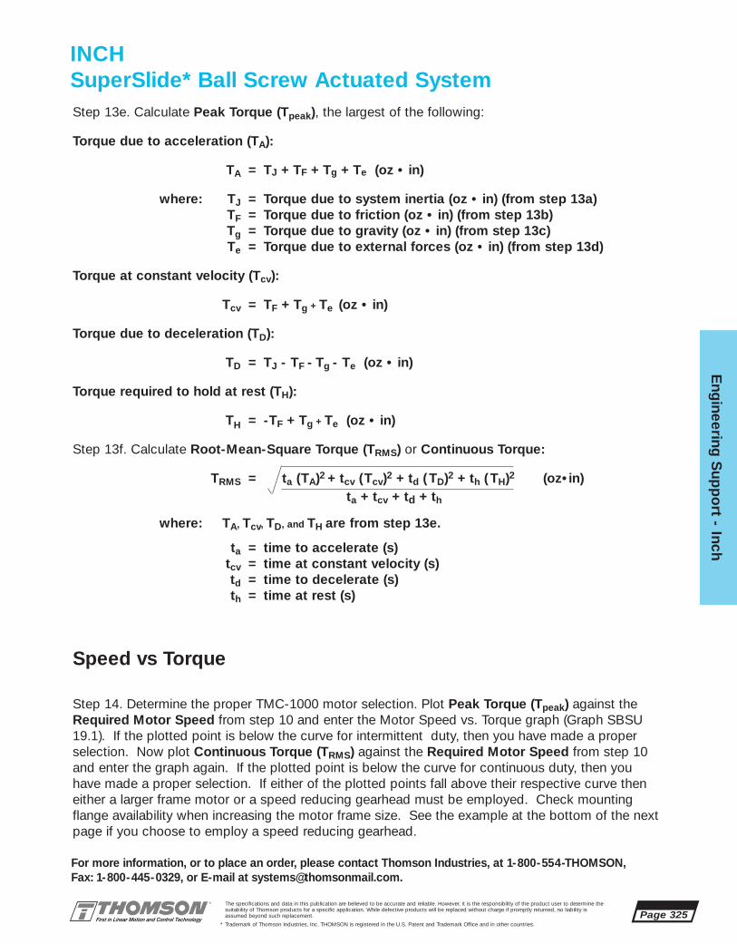
The specifications and data in this publication are believed to be accurate and reliable. However, it is the responsibility of the product user to determine thesuitability of Thomson products for a specific application. While defective products will be replaced without charge if promptly returned, no liability is assumed beyond such replacement.
* Trademark of Thomson Industries, Inc. THOMSON is registered in the U.S. Patent and Trademark Office and in other countries.
Eng
ineering S
upp
ort - Inch
Page 325
For more information, or to place an order, please contact Thomson Industries, at 1-800-554-THOMSON, Fax: 1-800-445-0329, or E-mail at [email protected].
Step 13e. Calculate Peak Torque (Tpeak), the largest of the following:
Torque due to acceleration (TA):
TA = TJ + TF + Tg + Te (oz • in)
where: TJ = Torque due to system inertia (oz • in) (from step 13a)TF = Torque due to friction (oz • in) (from step 13b)Tg = Torque due to gravity (oz • in) (from step 13c)Te = Torque due to external forces (oz • in) (from step 13d)
Torque at constant velocity (Tcv):
Tcv = TF + Tg + Te (oz • in)
Torque due to deceleration (TD):
TD = TJ - TF - Tg - Te (oz • in)
Torque required to hold at rest (TH):
TH = -TF + Tg + Te (oz • in)
Step 13f. Calculate Root-Mean-Square Torque (TRMS) or Continuous Torque:
TRMS = ta (TA)2 + tcv (Tcv)2 + td ( TD)2 + th ( TH)2 (oz•in)ta + tcv + td + th
where: TA, Tcv, TD, and TH are from step 13e.
ta = time to accelerate (s)tcv = time at constant velocity (s)td = time to decelerate (s)th = time at rest (s)
Speed vs Torque
Step 14. Determine the proper TMC-1000 motor selection. Plot Peak Torque (Tpeak) against theRequired Motor Speed from step 10 and enter the Motor Speed vs. Torque graph (Graph SBSU19.1). If the plotted point is below the curve for intermittent duty, then you have made a properselection. Now plot Continuous Torque (TRMS) against the Required Motor Speed from step 10and enter the graph again. If the plotted point is below the curve for continuous duty, then youhave made a proper selection. If either of the plotted points fall above their respective curve theneither a larger frame motor or a speed reducing gearhead must be employed. Check mountingflange availability when increasing the motor frame size. See the example at the bottom of the nextpage if you choose to employ a speed reducing gearhead.
INCHSuperSlide* Ball Screw Actuated System

Page 326The specifications and data in this publication are believed to be accurate and reliable. However, it is the responsibility of the product user to determine thesuitability of Thomson products for a specific application. While defective products will be replaced without charge if promptly returned, no liability is assumed beyond such replacement.
* Trademark of Thomson Industries, Inc. THOMSON is registered in the U.S. Patent and Trademark Office and in other countries.
Eng
inee
ring
Sup
po
rt -
Inc
h
For more information, or to place an order, please contact Thomson Industries, at 1-800-554-THOMSON, Fax: 1-800-445-0329, or E-mail at [email protected].
Motor Speed vs. Torque Curve
Graph SBSU 19.1 is an example of a speed vs.torque curve for a NEMA 23 motor from theMotion Control section. BLX Series motors areavailable in standard NEMA frame sizes 23, 34and 42 and can be combined with either a one,two, three or four axis controller. To determine themotor speed vs. torque curve that best suits theapplication and for a continuation of features andspecifications refer to the Motion Control section,page 371.
Speed vs. Torque Curve with Gearhead
There is an increased torque capability whenusing a gearhead. The use of a gearhead alsorequires the motor to run at a higher speed.Gearheads are available in standard NEMA framesizes 23, 34 and 42 and in ratios 1:1, 3:1; 5:1 and10:1 (other ratios are available). To determine themotor speed vs. torque curve that best suits theapplication and for a continuation of features andspecifications refer to the Motion Control section,page 371.
RPM = Vmax • 60 • iP
where: Vmax = maximum linear speed (in/s) (from step 9)P = lead of Ball or Lead screw (in/rev) (from table on page 323)i = gearhead ratio
To determine motor speed, use the following formula:
APx-232A-D010-Lxx
0
2
4
6
8
10
12
14
16
0 1000 2000 3000 4000 5000 6000
rpm
in-l
b
Graph SBSU 19.1
INCHSuperSlide* Ball Screw Actuated System
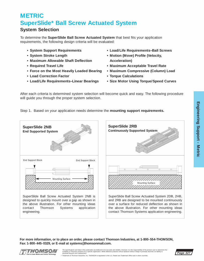
Eng
ineering S
upp
ort - M
etric
Page 327
For more information, or to place an order, please contact Thomson Industries, at 1-800-554-THOMSON, Fax: 1-800-445-0329, or E-mail at [email protected].
The specifications and data in this publication are believed to be accurate and reliable. However, it is the responsibility of the product user to determine thesuitability of Thomson products for a specific application. While defective products will be replaced without charge if promptly returned, no liability isassumed beyond such replacement.
* Trademark of Thomson Industries, Inc. THOMSON is registered in the U.S. Patent and Trademark Office and in other countries.
METRICSuperSlide* Ball Screw Actuated SystemSystem Selection
Mounting Surface
End Support Block End Support Block
To determine the SuperSlide Ball Screw Actuated System that best fits your applicationrequirements, the following design criteria will be evaluated:
After each criteria is determined system selection will become quick and easy. The following procedure will guide you through the proper system selection.
Step 1. Based on your application needs determine the mounting support requirements.
Mounting Surface
SuperSlide 2NBEnd Supported System
SuperSlide Ball Screw Actuated System 2NB isdesigned to quickly mount over a gap as shown inthe above illustration. For other mounting ideascontact Thomson Systems application engineering.
SuperSlide Ball Screw Actuated System 2DB, 2HB,and 2RB are designed to be mounted continuouslyover a surface for reduced deflection as shown inthe above illustration. For other mounting ideascontact Thomson Systems application engineering.
SuperSlide 2RBContinuously Supported System
• System Support Requirements• System Stroke Length• Maximum Allowable Shaft Deflection• Required Travel Life• Force on the Most Heavily Loaded Bearing• Load Correction Factor• Load/Life Requirements–Linear Bearings
• Load/Life Requirements–Ball Screws• Motion (Move) Profile (Velocity,
Acceleration)• Maximum Acceptable Travel Rate• Maximum Compressive (Column) Load• Torque Calculations• Size Motor Using Torque/Speed Curves
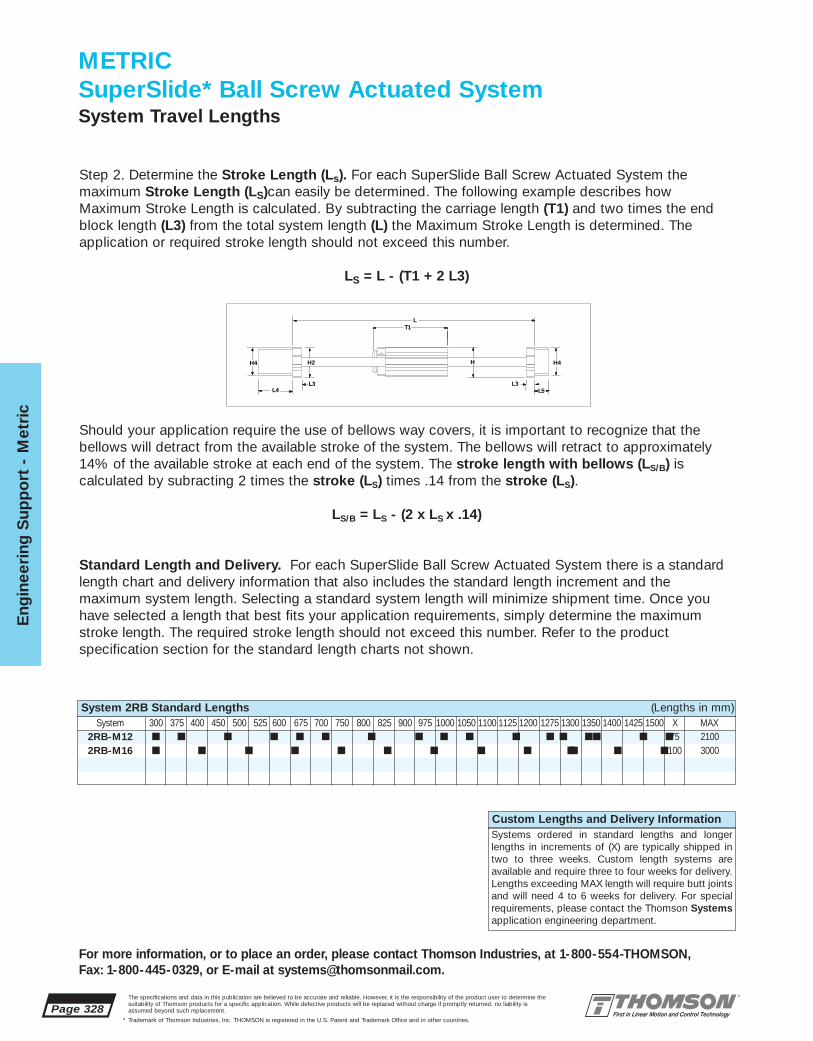
Page 328
Eng
inee
ring
Sup
po
rt -
Met
ric
For more information, or to place an order, please contact Thomson Industries, at 1-800-554-THOMSON, Fax: 1-800-445-0329, or E-mail at [email protected].
The specifications and data in this publication are believed to be accurate and reliable. However, it is the responsibility of the product user to determine thesuitability of Thomson products for a specific application. While defective products will be replaced without charge if promptly returned, no liability isassumed beyond such replacement.
* Trademark of Thomson Industries, Inc. THOMSON is registered in the U.S. Patent and Trademark Office and in other countries.
2RB-M12 ■ ■ ■ ■ ■ ■ ■ ■ ■ ■ ■ ■ ■
2RB-M16 ■ ■ ■ ■ ■ ■ ■ ■ ■ ■
■ ■ ■ ■75 2100■ ■ ■100 3000
Should your application require the use of bellows way covers, it is important to recognize that the bellows will detract from the available stroke of the system. The bellows will retract to approximately14% of the available stroke at each end of the system. The stroke length with bellows (LS/B) is calculated by subracting 2 times the stroke (LS) times .14 from the stroke (LS).
LS/B = LS - (2 x LS x .14)
Standard Length and Delivery. For each SuperSlide Ball Screw Actuated System there is a standardlength chart and delivery information that also includes the standard length increment and the maximum system length. Selecting a standard system length will minimize shipment time. Once youhave selected a length that best fits your application requirements, simply determine the maximumstroke length. The required stroke length should not exceed this number. Refer to the product specification section for the standard length charts not shown.
L
L4
H4
L3
T1
HH2
L3L5
H4
Step 2. Determine the Stroke Length (Ls). For each SuperSlide Ball Screw Actuated System the maximum Stroke Length (LS)can easily be determined. The following example describes how Maximum Stroke Length is calculated. By subtracting the carriage length (T1) and two times the endblock length (L3) from the total system length (L) the Maximum Stroke Length is determined. The application or required stroke length should not exceed this number.
LS = L - (T1 + 2 L3)
METRICSuperSlide* Ball Screw Actuated SystemSystem Travel Lengths
System 2RB Standard Lengths (Lengths in mm)System 300 375 400 450 500 525 600 675 700 750 800 825 900 975 1000 1050 1100 1125 1200 1275 1300 1350 1400 1425 1500 X MAX
Custom Lengths and Delivery InformationSystems ordered in standard lengths and longerlengths in increments of (X) are typically shipped intwo to three weeks. Custom length systems are available and require three to four weeks for delivery.Lengths exceeding MAX length will require butt jointsand will need 4 to 6 weeks for delivery. For specialrequirements, please contact the Thomson Systemsapplication engineering department.

Eng
ineering S
upp
ort - M
etric
Page 329
For more information, or to place an order, please contact Thomson Industries, at 1-800-554-THOMSON, Fax: 1-800-445-0329, or E-mail at [email protected].
The specifications and data in this publication are believed to be accurate and reliable. However, it is the responsibility of the product user to determine thesuitability of Thomson products for a specific application. While defective products will be replaced without charge if promptly returned, no liability isassumed beyond such replacement.
* Trademark of Thomson Industries, Inc. THOMSON is registered in the U.S. Patent and Trademark Office and in other countries.
Travel Life
Step 4. Determine the Required Travel Life (km).
Lt = required travel life (km)Lt = 2 • s • f • Lh • 60 s = stroke (mm)
f = frequency (cycles/minute)Lh= service life (hrs)
100 000
50 000
20 000
10 000
5 000
2 000
1 000
500
200
1000 1 2
System Length (m)
Load
on
Sys
tem
(N)
Maximum Recommended Load on System
2NB-M20
2NB-M16
Step 3. For end supported systems, determine if the system selected meets the Maximum AllowableDeflection criteria.
In end supported applications the bearing system canwithstand an enormous amount of system deflection andstill run smoothly due to the universal self-aligning feature of the Super Smart Ball Bushing* bearing. In aBall Screw actuated end supported application, deflec-tion is limited by the amount of radial load that a ballscrew assembly can withstand. Step 3 will determine ifthe system size and length can handle the applied load.For SuperSlide Ball Screw Actuated System 2NB there isa graph (SBSM 7.1) that gives the maximum recom-mended load on the system based on shaft and ballscrew deflection. To determine the system that bestmeets your application requirements, simply enter thegraph with the total load on the system and the overallsystem length. Select a system characteristic curve thatis above or to the right of the plotted point. To determinethe actual deflection see the Engineering SupportSection, page 378.
METRICSuperSlide* Ball Screw Actuated SystemMaximum Allowable DeflectionEnd Supported Systems
SuperSlide 2NBEnd Supported System
Graph (SBSM 7.1)
106
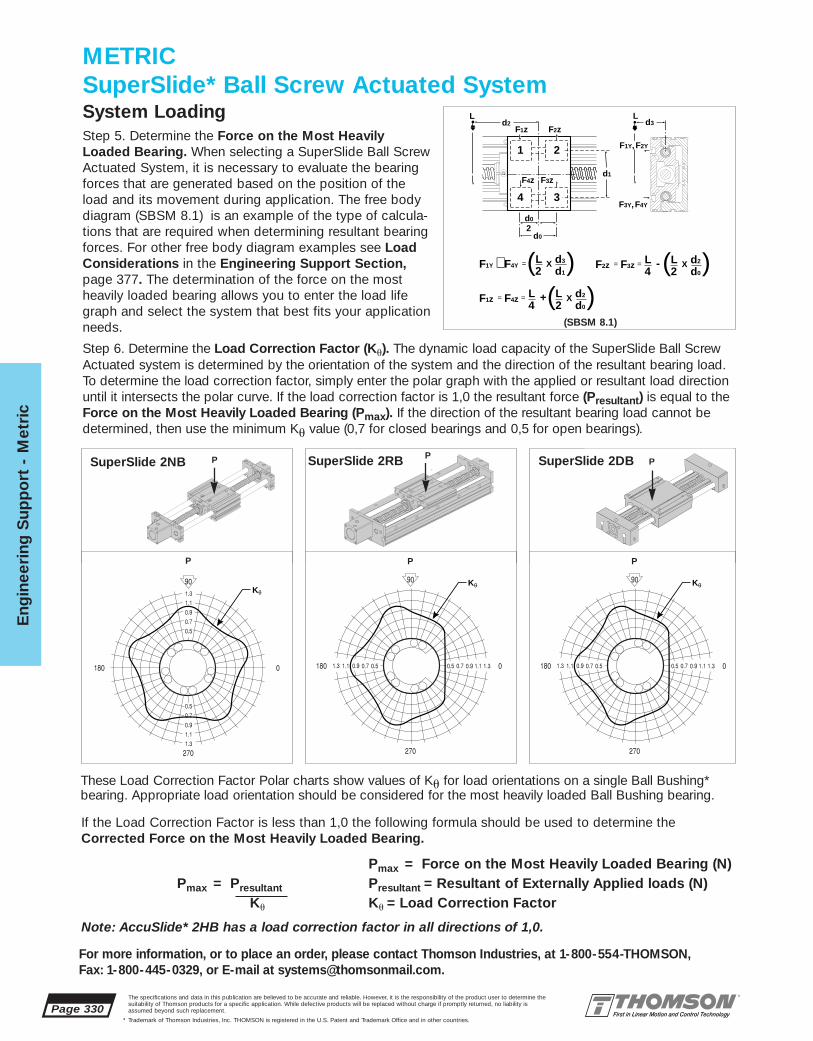
Page 330
Eng
inee
ring
Sup
po
rt -
Met
ric
For more information, or to place an order, please contact Thomson Industries, at 1-800-554-THOMSON, Fax: 1-800-445-0329, or E-mail at [email protected].
The specifications and data in this publication are believed to be accurate and reliable. However, it is the responsibility of the product user to determine thesuitability of Thomson products for a specific application. While defective products will be replaced without charge if promptly returned, no liability isassumed beyond such replacement.
* Trademark of Thomson Industries, Inc. THOMSON is registered in the U.S. Patent and Trademark Office and in other countries.
If the Load Correction Factor is less than 1,0 the following formula should be used to determine theCorrected Force on the Most Heavily Loaded Bearing.
Pmax = Force on the Most Heavily Loaded Bearing (N)Pmax = Presultant Presultant = Resultant of Externally Applied loads (N)
Ku Ku = Load Correction Factor
Note: AccuSlide* 2HB has a load correction factor in all directions of 1,0.
Step 6. Determine the Load Correction Factor (Ku). The dynamic load capacity of the SuperSlide Ball ScrewActuated system is determined by the orientation of the system and the direction of the resultant bearing load.To determine the load correction factor, simply enter the polar graph with the applied or resultant load directionuntil it intersects the polar curve. If the load correction factor is 1,0 the resultant force (Presultant) is equal to theForce on the Most Heavily Loaded Bearing (Pmax). If the direction of the resultant bearing load cannot bedetermined, then use the minimum Ku value (0,7 for closed bearings and 0,5 for open bearings).
SuperSlide 2NB
Step 5. Determine the Force on the Most HeavilyLoaded Bearing. When selecting a SuperSlide Ball ScrewActuated System, it is necessary to evaluate the bearingforces that are generated based on the position of theload and its movement during application. The free bodydiagram (SBSM 8.1) is an example of the type of calcula-tions that are required when determining resultant bearingforces. For other free body diagram examples see LoadConsiderations in the Engineering Support Section,page 377. The determination of the force on the mostheavily loaded bearing allows you to enter the load lifegraph and select the system that best fits your applicationneeds.
1 2
4 3
L L
2
d2
d0
d0
d3
d1
F1z F2z
F2Y
F4z
F3Y,
F3z
F4Y
F1Y F4YL2
d3
d1∼ =( (X
F1z F4z L2
L4
d2
d0== ( X+ (
24 d0F2z F3z LL d2== ( (X-
F1Y,
PP
METRICSuperSlide* Ball Screw Actuated SystemSystem Loading
SuperSlide 2DB PSuperSlide 2RB
(SBSM 8.1)
These Load Correction Factor Polar charts show values of Ku for load orientations on a single Ball Bushing*bearing. Appropriate load orientation should be considered for the most heavily loaded Ball Bushing bearing.
KθKθ
Kθ
P P P

Eng
ineering S
upp
ort - M
etric
Page 331
For more information, or to place an order, please contact Thomson Industries, at 1-800-554-THOMSON, Fax: 1-800-445-0329, or E-mail at [email protected].
The specifications and data in this publication are believed to be accurate and reliable. However, it is the responsibility of the product user to determine thesuitability of Thomson products for a specific application. While defective products will be replaced without charge if promptly returned, no liability isassumed beyond such replacement.
* Trademark of Thomson Industries, Inc. THOMSON is registered in the U.S. Patent and Trademark Office and in other countries.
Load/Life GraphLines indicate limiting load for given shaft size
Lo
ad o
n m
ost
hea
vily
load
ed b
eari
ng
(N
)
1010
100
100
1 000
1 000
10 000
10 000
100 000
Required Travel Life (km)
2RB-M16
2RB-M302RB-M25
2RB-M20
2RB-M12
For each SuperSlide Ball Screw Actuated Systemthere is a graph (SBSM 9.1) that allows for systemselection based on the Required Travel Life andthe Force on the Most Heavily Loaded Bearing.To determine the system which best meets yourapplication Load and Life requirements, simplyenter the graph with your Required Travel Lifefrom step 4 and the Corrected Force on the MostHeavily Loaded Bearing from step 6. Select a sys-tem characteristic curve that is above or to the rightof the plotted point.
Note: Use Corrected Force on the Most HeavilyLoaded Bearing if load correction factor is lessthan 1,0.
Step 7. Select the system that meets the application Load and Life Requirements.
Graph (SBSM 9.1)
Step 8. Confirm that the Ball Screw in the SuperSlide selected will achieve Load and lifeRequirements. Once the SuperSlide Ball Screw Actuated System is selected refer to the Ball ScrewCompatability Charts on the next page and select a ball screw that meets your application needs.With the Ball Screw axial load and the required travel life enter the graph below.
Load/Life GraphBall Screw Travel Life vs. Load
Axi
al L
oad
on
Bal
l Scr
ew (
N)
Required Travel Life (km)
25 x 25P
25 x 10P
25 x 5P
20 x 20P20 x 5P
16 x 5P, 20 x 10P16 x 10P, 16 x 16P
100 1 000
300
10 000
1 000
100 000
10 000
20 000To use the Ball ScrewLoad/Life graph (SBSM 9.2),simply enter the graph withthe axial load on the ballscrew and the required travellife. Select a SuperSlide BallScrew characteristic curve tothe right or above of where the two lines intersect.
METRICSuperSlide* Ball Screw Actuated SystemLoad and Life Requirements
Graph (SBSM 9.2)
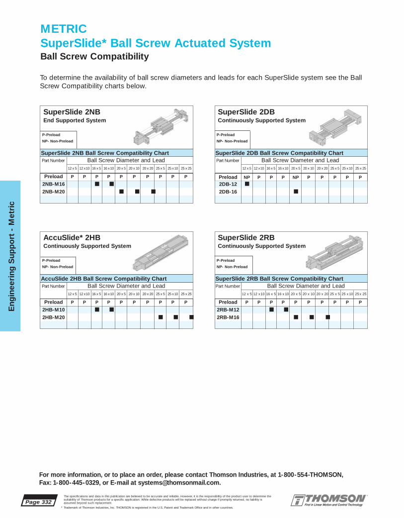
Page 332
Eng
inee
ring
Sup
po
rt -
Met
ric
For more information, or to place an order, please contact Thomson Industries, at 1-800-554-THOMSON, Fax: 1-800-445-0329, or E-mail at [email protected].
The specifications and data in this publication are believed to be accurate and reliable. However, it is the responsibility of the product user to determine thesuitability of Thomson products for a specific application. While defective products will be replaced without charge if promptly returned, no liability isassumed beyond such replacement.
* Trademark of Thomson Industries, Inc. THOMSON is registered in the U.S. Patent and Trademark Office and in other countries.
Preload P P P P P P P P P P
2RB-M12 ■ ■
2RB-M16 ■ ■ ■
Preload P P P P P P P P P P
2HB-M10 ■ ■
2HB-M20 ■ ■ ■
Preload NP P P P NP P P P P P
2DB-12 ■
2DB-16 ■
Preload P P P P P P P P P P
2NB-M16 ■ ■
2NB-M20 ■ ■ ■
P-Preload
NP- Non-Preload
SuperSlide 2NBEnd Supported System
METRICSuperSlide* Ball Screw Actuated SystemBall Screw Compatibility
Part Number Ball Screw Diameter and Lead 12 x 5 12 x10 16 x 5 16 x10 20 x 5 20 x 10 20 x 20 25 x 5 25 x10 25 x 25
SuperSlide 2NB Ball Screw Compatibility Chart
P-Preload
NP- Non-Preload
SuperSlide 2DBContinuously Supported System
Part Number Ball Screw Diameter and Lead 12 x 5 12 x10 16 x 5 16 x10 20 x 5 20 x 10 20 x 20 25 x 5 25 x10 25 x 25
SuperSlide 2DB Ball Screw Compatibility Chart
P-Preload
NP- Non-Preload
AccuSlide* 2HBContinuously Supported System
Part Number Ball Screw Diameter and Lead 12 x 5 12 x10 16 x 5 16 x10 20 x 5 20 x 10 20 x 20 25 x 5 25 x10 25 x 25
AccuSlide 2HB Ball Screw Compatibility Chart
P-Preload
NP- Non-Preload
SuperSlide 2RBContinuously Supported System
Part Number Ball Screw Diameter and Lead 12 x 5 12 x10 16 x 5 16 x 10 20 x 5 20 x 10 20 x 20 25 x 5 25 x 10 25 x 25
SuperSlide 2RB Ball Screw Compatibility Chart
To determine the availability of ball screw diameters and leads for each SuperSlide system see the BallScrew Compatibility charts below.
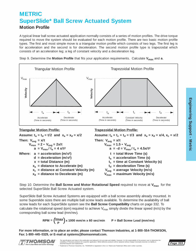
Eng
ineering S
upp
ort - M
etric
Page 333
For more information, or to place an order, please contact Thomson Industries, at 1-800-554-THOMSON, Fax: 1-800-445-0329, or E-mail at [email protected].
The specifications and data in this publication are believed to be accurate and reliable. However, it is the responsibility of the product user to determine thesuitability of Thomson products for a specific application. While defective products will be replaced without charge if promptly returned, no liability isassumed beyond such replacement.
* Trademark of Thomson Industries, Inc. THOMSON is registered in the U.S. Patent and Trademark Office and in other countries.
METRICSuperSlide* Ball Screw Actuated SystemMotion Profile
A typical linear ball screw actuated application normally consists of a series of motion profiles. The drive torquerequired to move the system should be evaluated for each motion profile. There are two basic motion profiletypes. The first and most simple move is a triangular motion profile which consists of two legs. The first leg isfor acceleration and the second is for deceleration. The second motion profile type is trapezoidal which consists of an acceleration leg; a leg of constant velocity and a deceleration leg.
Vmax Vmax
ta td
Accelerate(Time in seconds)
Decelerate(Time in seconds)
ta
Accelerate(Time in seconds)
td
Decelerate(Time in seconds)
tc
Constant Velocity(Time in seconds)
Velo
city
Velo
city
Triangular Motion Profile Trapezoidal Motion Profile
Step 9. Determine the Motion Profile that fits your application requirements. Calculate Vmax and a.
SuperSlide Ball Screw Actuated Systems are equipped with a ball screw assembly already mounted. Insome Superslide sizes there are multiple ball screw leads available. To determine the availability of ballscrew leads for each SuperSlide system see the Ball Screw Compatibility charts on page 332. To calculate the rotational speed (rpm) required to achieve Vmax simply divide the linear speed (m/s) by thecorresponding ball screw lead (mm/rev).
RPM = (Vmax) x 1000 mm/m x 60 sec/min P = Ball Screw Lead (mm/rev)P
Step 10. Determine the Ball Screw and Motor Rotational Speed required to move at Vmax for theselected SuperSlide Ball Screw Actuated system.
Trapezoidal Motion Profile:
Assume: ta = tc = td = t/3 and xa = xd = x/4, xc = x/2
Then: Vavg = x/tVmax = 1.5 • Vavg
a = -d = Vmax / ta = 4.5x/t2
t = total Move Time (s)ta = acceleration Time (s)tc = time at Constant Velocity (s)td = deceleration Time (s)
Vavg = average Velocity (m/s)Vmax = maximum Velocity (m/s)
Triangular Motion Profile:
Assume: ta = td = t/2 and xa = xd = x/2
Then: Vavg = x/tVmax = 2 • Vavg = 2x/t
a = Vmax / ta = 4 x/t2
Where: a = acceleration (m/s2)d = deceleration (m/s2)x = total Distance (m)
xa = distance to Accelerate (m)xc = distance at Constant Velocity (m)xd = distance to Decelerate (m)

Page 334
Eng
inee
ring
Sup
po
rt -
Met
ric
For more information, or to place an order, please contact Thomson Industries, at 1-800-554-THOMSON, Fax: 1-800-445-0329, or E-mail at [email protected].
The specifications and data in this publication are believed to be accurate and reliable. However, it is the responsibility of the product user to determine thesuitability of Thomson products for a specific application. While defective products will be replaced without charge if promptly returned, no liability isassumed beyond such replacement.
* Trademark of Thomson Industries, Inc. THOMSON is registered in the U.S. Patent and Trademark Office and in other countries.
Each SuperSlide Ball Screw Actuated System has a Maximum Acceptable Travel Rate based onthe natural frequency of the whirling vibration of the ball screw. To determine the SuperSlide system that is capable of achieving the applications speeds, simply enter the graph with theMaximum Ball Screw Rotational Speed from step 10 and the required system length. Select theSuperslide system characteristic curve to the right or above the plotted point.
Step 11. Confirm the system application Maximum Ball Screw Rotational Speed is below theMaximum Acceptable Travel Rate.
METRICSuperSlide* Ball Screw Actuated SystemMaximum Acceptable Travel Rate
Maximum AcceptableTravel Rate✝
5000
1000
500
System Length (mm)✝80% of Critical Speed
400 1000 2000
Ro
tati
ona
l Sp
eed
(rev
/min
)
1003000
16 x 5 P, 16 x 10P, 16 x 16P
25 x 5 P, 25 x 10 P, 25 x 25 P
20 x 5 P, 20 x 10 P, 20 x 20 P

Eng
ineering S
upp
ort - M
etric
Page 335
For more information, or to place an order, please contact Thomson Industries, at 1-800-554-THOMSON, Fax: 1-800-445-0329, or E-mail at [email protected].
The specifications and data in this publication are believed to be accurate and reliable. However, it is the responsibility of the product user to determine thesuitability of Thomson products for a specific application. While defective products will be replaced without charge if promptly returned, no liability isassumed beyond such replacement.
* Trademark of Thomson Industries, Inc. THOMSON is registered in the U.S. Patent and Trademark Office and in other countries.
Compressive Load
10000
1000
500
Co
mp
ress
ive
Load
on
Scr
ew (N
)
10 100
1000
2000
Mass on Carriage (kg)
Acceleration (m/s2)30 20 10
8
65
4
3
2
1
100
Maximum AllowableCompressive Load
10000
1000
500
Max
imum
Allo
wab
le C
om
pre
ssiv
e Lo
ad (N
)
1000
System Length (mm)
100
100 2000 3000
16 x 5 P
25 x 5 P
25 x 10 P
20 x 20 P20 x 5 P
25 x 25 P
16 x 10 P16 x 16 P
20 x 10 P
METRICSuperSlide* Ball Screw Actuated SystemMaximum Compressive Load
Step 12. Determine if the application loads on the SuperSlide exceed the maximum compressiveload limits of the ball screw. Determine the Actual Compressive Load and the MaximumAllowable Compressive Load.
Graph SBSM13.1 is used to determine the Actual Compressive Load on the system ball screwcaused by the load on the carriage and the system acceleration. To determine the ActualCompressive Load, enter the graph with the mass on the carriage and intersect this line with the system acceleration and locate the compressive load on the ball screw.
Graph SBSM13.2 is used to determine the Maximum Allowable Compressive Load for eachSuperslide Ball Screw Actuated system. To determine the Maximum Allowable CompressiveLoad, enter the graph with the actual compressive load from (Graph 13.1) and intersect this linewith the system length. Select a system with a rated maximum compressive load characteristiccurve above or to the right of your plotted point.
Note: If the Actual Compressive Load is higher that the Maximum Allowable CompressiveLoad than the system size, length, load or acceleration should be reconsidered.
Graph (SBSM 13.1) Graph (SBSM 13.2)

Page 336
Eng
inee
ring
Sup
po
rt -
Met
ric
For more information, or to place an order, please contact Thomson Industries, at 1-800-554-THOMSON, Fax: 1-800-445-0329, or E-mail at [email protected].
The specifications and data in this publication are believed to be accurate and reliable. However, it is the responsibility of the product user to determine thesuitability of Thomson products for a specific application. While defective products will be replaced without charge if promptly returned, no liability isassumed beyond such replacement.
* Trademark of Thomson Industries, Inc. THOMSON is registered in the U.S. Patent and Trademark Office and in other countries.
METRICSuperSlide Ball Screw Actuated SystemTorque Calculations
Step 13. In order to size a motor for your SuperSlide Ball Screw Actuated system it is important to calculatethe torque required to meet your application requirements with all of the parameters in mind. If you are actu-ating your system with a stepping motor, then a maximum or peak torque (Tpeak) calculation is required.Peak torque is usually seen at the time of maximum acceleration, however, other factors such as torque dueto external forces can affect when peak torque occurs. It is important to calculate for all torque conditions(Torque due to acceleration (TA), Torque at constant velocity (Tcv), Torque due to deceleration (TD), andTorque required to hold at rest (TH)), and take that torque with the largest magnitude as the Peak Torque(Tpeak).
TA = TJ + TF + Tg + Te (N • m)Tcv = TF + Tg + Te (N • m)TD = TJ - TF - Tg - Te (N • m)TH = -TF + Tg + Te (N • m)
where: TJ = Torque due to system inertia (N • m)TF = Torque due to friction (N • m)Tg = Torque due to gravity (N • m)Te = Torque due to external forces (N • m)
Should you be actuating your Superslide system with a servo motor system then it is also necessary to calculate a Root-Mean-Square Torque (TRMS) or Continuous Torque.
TRMS = ta ( TA)2 + tcv (Tcv)2 + td (TD)2 + th (TH)2 (N • m)
ta + tcv + td + th
where: ta = time to accelerate (s)tcv = time at constant velocity (s)td = time to decelerate (s)th = time at rest (s)
Step 13a. Calculate Torque due to system inertia (TJ):
TJ = v JL + JB + JM (N • m)g • ta jscrew
where: v = angular velocity (rad/s)JL = Load inertia (N • m2)JB = Ball Screw inertia (N • m2)JM = Motor inertia (N • m2)(1) (1 g • cm2 = 10- 8 N • m2)ta = Time for acceleration (s) (from step 9)g = Acceleration due to gravity = 9.81 m/s2
jscrew = Efficiency of Ball Screw = 90%(1) For motor inertia data see the Motion Control Section, page 431
Calculate Load inertia (JL):
JL = (Wc + Wp) (P/1000)2 (N • m2)
(2p)2
where: Wc = Weight of the Carriage (N) (from table on next page)Wp = Weight of Payload (N) (from Application Data)
P = Lead of Ball or Lead Screw (mm) (from table on page 338)p = 3.1416
]]

2DB-12 12 16,7 0,002 4 0,72DB-16 16 34,3 0,002 4 1,2
2RB-M12 12 8,8 0,002 8 0,52RB-M16 16 16,7 0,002 8 0,7
2HB-M10 10 3,9 0,003 4 0,92HB-M20 20 26,5 0,003 4 7,0
Eng
ineering S
upp
ort - M
etric
Page 337
For more information, or to place an order, please contact Thomson Industries, at 1-800-554-THOMSON, Fax: 1-800-445-0329, or E-mail at [email protected].
The specifications and data in this publication are believed to be accurate and reliable. However, it is the responsibility of the product user to determine thesuitability of Thomson products for a specific application. While defective products will be replaced without charge if promptly returned, no liability isassumed beyond such replacement.
* Trademark of Thomson Industries, Inc. THOMSON is registered in the U.S. Patent and Trademark Office and in other countries.
2NB-M16 16 0,002 8 0,72NB-M20 20 22,6 0,002 8 1,2
Part System Carriage Carriage Number SealNumber Size Weight Friction of Drag
(N) Coefficient Seals (N)
SuperSlide 2NB
Part System Carriage Carriage Number SealNumber Size Weight Friction of Drag
(N) Coefficient Seals (N)
SuperSlide 2RB Ball Screw Actuated System Data
SuperSlide 2DB
Part System Carriage Carriage Number SealNumber Size Weight Friction of Drag
(N) Coefficient Seals (N)
AccuSlide 2NB Ball Screw Actuated System Data
AccuSlide 2HB
Part System Carriage Carriage Number SealNumber size Weight Friction of Drag
(N) Coefficient Seals (N)
SuperSlide 2RB Ball Screw Actuated System Data
SuperSlide 2RB
SuperSlide 2NB Ball Screw Actuated System Data
Calculate Ball or Lead Screw inertia (JB):
JB = p L r (d/1000)4 (N • m2)32
L = Length of Ball Screw (m)r = Density of Ball Screw = 76,400 N/m3
d = Diameter of Ball Screw (mm) (from table on next page)
Calulate angular velocity (v):
v = 2p Vmax (rad/S)
(P/1000)
where: Vmax = Maximum Linear Speed (m/s) (from step 9)P = Lead of Ball Screw (mm) (from table on next page)
With the calculated values of Load inertia (JL), Ball or Lead Screw inertia (JB), and Angular Velocity (v )you can now calculate Torque due to system inertia (TJ):
TJ = v JL + JB + JM (N • m)g • ta jscrew
Step 13b. Calculate Torque due to friction (TF)
TF = (P/1000) • Pf + Tr (N • m)2p jscrew
]]
METRICSuperSlide* Ball Screw Actuated System

Page 338
Eng
inee
ring
Sup
po
rt -
Met
ric
For more information, or to place an order, please contact Thomson Industries, at 1-800-554-THOMSON, Fax: 1-800-445-0329, or E-mail at [email protected].
The specifications and data in this publication are believed to be accurate and reliable. However, it is the responsibility of the product user to determine thesuitability of Thomson products for a specific application. While defective products will be replaced without charge if promptly returned, no liability isassumed beyond such replacement.
* Trademark of Thomson Industries, Inc. THOMSON is registered in the U.S. Patent and Trademark Office and in other countries.
2RB-M12-ODM-G 12 16 x 5 0,092RB-M12-ODM-H 12 16 x 10 0,092RB-M16-ODM-I 16 20 x 5 0,12RB-M16-ODM-J 16 20 x 10 0,12RB-M16-ODM-K 16 20 x 20 0,1
2HB-M10-OYP-G 10 16 x 5 0,092HB-M10-OYP-H 10 16 x 10 0,092HB-M20-OYP-L 20 25 x 5 0,12HB-M20-OYP-M 20 25 x 10 0,12HB-M10-OYP-N 20 25 x 25 0,1
2DB-12-OUK-B 12 12 x 5 0,052DB-16-OUK-D 16 20 x 5 0,07
2NB-M20-OGL-I 20 20 X 5 0,12NB-M20-OGL-J 20 20 X 10 0,12NB-M20-OGL-K 20 20 X 20 0,1
SuperSlide 2NB Ball Screw Act. System DataPart Nominal Ball Screw Frictional
Number Dia. Dia.x lead Torque N-m(mm) Tr †
SuperSlide 2NB
Part System Ball Screw Frictional Number Dia. Dia.x lead Torque N-m
(mm) Tr †
SuperSlide 2DB Ball Screw Act. System Data
Part Nominal Ball Screw Frictional Number Size Dia.x lead Torque N-m
(mm) Tr †
AccuSlide 2HB Ball Screw Act. System Data
AccuSlide* 2HB SuperSlide 2RB
SuperSlide 2DB
Part Nominal Ball Screw Frictional Number Dia. Dia.x lead Torque N-m
(mm) Tr †
SuperSlide 2RB Ball Screw Act. System Data
† Values of Tr are provided for calculation purposes. Measured values of Tr will vary with radial bearing and ball nut preload.
where: P = Lead of Ball Screw (mm) (from table above)p = 3.1416
j screw = Efficiency of Ball Screw = 90%
Calculate Friction Force (Pf):
Pf = (Wc + Wp) • msys + n• Ds (N)
where: Wc = Weight of Carriage (N) (from table on previous page)Wp = Weight of Payload (N) (from Application Data)
msys = Coefficient of friction of carriage (from table on previous page)n = number of seals (from table on previous page)
Ds = Seal Drag (N) (from table on previous page)
With the calculated value of Frictional Force (PF), locate Frictional Torque (Tr) (N • m) in theappropriate table above and calculate Torque due to friction (TF) from the formula on the previouspage.
Step 13c. Calculate Torque due to gravity (Tg):
Tg = (P/1000) • Pg (N • m)2p jscrew
where: P = Lead of Ball Screw (mm) (from table above)p = 3.1416
jscrew = Efficiency of Ball Screw = 90%
METRICSuperSlide* Ball Screw Actuated System
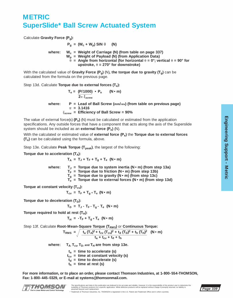
Eng
ineering S
upp
ort - M
etric
Page 339
For more information, or to place an order, please contact Thomson Industries, at 1-800-554-THOMSON, Fax: 1-800-445-0329, or E-mail at [email protected].
The specifications and data in this publication are believed to be accurate and reliable. However, it is the responsibility of the product user to determine thesuitability of Thomson products for a specific application. While defective products will be replaced without charge if promptly returned, no liability isassumed beyond such replacement.
* Trademark of Thomson Industries, Inc. THOMSON is registered in the U.S. Patent and Trademark Office and in other countries.
Calculate Gravity Force (Pg):
Pg = (Wc + Wp) SIN θ (N)
where: Wc = Weight of Carriage (N) (from table on page 337)Wp = Weight of Payload (N) (from Application Data)
u = Angle from horizontal (for horizontal u = 0°; vertical u = 90° forupstroke, u = 270° for downstroke)
With the calculated value of Gravity Force (Pg) (N), the torque due to gravity (Tg) can be calculated from the formula on the previous page.
Step 13d. Calculate Torque due to external forces (Te):
Te = (P/1000) • Pe (N • m)2p ξscrew
where: P = Lead of Ball Screw (mm/rev) (from table on previous page)p = 3.1416
jscrew = Efficiency of Ball Screw = 90%
The value of external force(s) (Pe) (N) must be calculated or estimated from the application specifications. Any outside forces that have a component that acts along the axis of the Superslidesystem should be included as an external force (Pe) (N).
With the calculated or estimated value of external force (Pe) the Torque due to external forces(Te) can be calculated using the formula, above.
Step 13e. Calculate Peak Torque (Tpeak), the largest of the following:
Torque due to acceleration (TA):TA = TJ + TF + Tg + Te (N • m)
where: TJ = Torque due to system inertia (N • m) (from step 13a)TF = Torque due to friction (N • m) (from step 13b)Tg = Torque due to gravity (N • m) (from step 13c)Te = Torque due to external forces (N • m) (from step 13d)
Torque at constant velocity (Tcv):Tcv = TF + Tg + Te (N • m)
Torque due to deceleration (TD):TD = TJ - TF - Tg - Te (N • m)
Torque required to hold at rest (TH):TH = -TF + Tg + Te (N • m)
Step 13f. Calculate Root-Mean-Square Torque (TRMS) or Continuous Torque:TRMS = ta (TA)2 + tcv (Tcv)2 + td (TD)2 + th (TH)2 (N • m)
ta + tcv + td + th
where: TA, Tcv, TD, and TH are from step 13e.
ta = time to accelerate (s)tcv = time at constant velocity (s)td = time to decelerate (s)th = time at rest (s)
METRICSuperSlide* Ball Screw Actuated System

Page 340
Eng
inee
ring
Sup
po
rt -
Met
ric
For more information, or to place an order, please contact Thomson Industries, at 1-800-554-THOMSON, Fax: 1-800-445-0329, or E-mail at [email protected].
The specifications and data in this publication are believed to be accurate and reliable. However, it is the responsibility of the product user to determine thesuitability of Thomson products for a specific application. While defective products will be replaced without charge if promptly returned, no liability isassumed beyond such replacement.
* Trademark of Thomson Industries, Inc. THOMSON is registered in the U.S. Patent and Trademark Office and in other countries.
Graph SBSM18.1
Motor Speed vs. Torque Curve
Graph SBSM18.1 is an example of a speedvs. torque curve for a NEMA 23 motor fromthe Motion Control section. BLX Seriesmotors are available in standard NEMA framesizes 23, 34 and 42 and can be combinedwith either a one, two, three or four axis controller. To determine the motor speed vs.torque curve that best suits the applicationand for a continuation of features and specifications refer to the Motion Control section, page 381.
Speed vs. Torque Curve with Gearhead
There is an increased torque capability when using a gearhead. The use of a gearhead also requires the motor torun at a higher speed. Gearheads are available in standardNEMA frame sizes 23, 34 and 42 and in ratios 1:1, 3:1, 5:1 and10:1. (other ratios are available). To determine the motor speedvs. torque curve that best suits the application and for a continuation of features and specifications refer to the MotionControl section, page 381.
RPM = Vmax • 60000 • iP
where: Vmax = maximum linear speed (m/s) (from step 9)P = lead of Ball Screw (mm/rev)i = gearhead ratio (from Application Data)
METRICSuperSlide* Ball Screw Actuated SystemSpeed vs Torque
Step 14. Determine the proper motor selection. Plot Peak Torque (Tpeak) against the Required MotorSpeed from step 10 and enter the Motor Speed vs. Torque graph (SBSM 18.1). If the plotted point isbelow the curve for intermittent duty, then you have made a proper selection. Now plot ContinuousTorque (TRMS) against the Required Motor Speed from step 10 and enter the graph again. If the plotted point is below the curve for continuous duty, then you have made a proper selection. If either ofthe plotted points fall above their respective curve then either a larger frame motor or a speed reducinggearhead must be employed. Check mounting flange availability when increasing the motor frame size.See the example at the bottom of this page if you choose to employ a speed reducing gearhead.
To determine motor speed, use the following formula:
APx-232A-D010-Lxx
0
2
4
6
8
10
12
14
16
0 1000 2000 3000 4000 5000 6000
rpm
in-l
b

TNUT-01-M3 7 4 1,75 1,25 3 M3TNUT-02-M4 9,5 5,5 2,25 1,75 4 M4TNUT-03-M4 12 7 2,5 2,5 5 M4TNUT-03-M5 12 7 2,5 2,5 5 M5TNUT-04-M4 16,5 7,9 4,8 1,2 6 M4TNUT-04-M5 M5TNUT-04-M6 M6TNUT-05-M4 19,5 9,8 5,8 2,8 8,6 M4TNUT-05-M5 M5TNUT-05-M6 M6TNUT-05-M8 M8
Eng
ineering S
upp
ort - M
etric
Page 341
For more information, or to place an order, please contact Thomson Industries, at 1-800-554-THOMSON, Fax: 1-800-445-0329, or E-mail at [email protected].
The specifications and data in this publication are believed to be accurate and reliable. However, it is the responsibility of the product user to determine thesuitability of Thomson products for a specific application. While defective products will be replaced without charge if promptly returned, no liability isassumed beyond such replacement.
* Trademark of Thomson Industries, Inc. THOMSON is registered in the U.S. Patent and Trademark Office and in other countries.
METRICSuperSlide* Ball Screw Actuated SystemSystem Mounting
The SuperSlide 2NB and 2RB Ball Screw Actuated Systems can be mounted using the T-nuts and T-slots from above with clamping fixtures as shown below. In addition, SuperSlide Ball Screw Actuated Systems 2NB and 2RB can be mounted using the bolt down attachment holes found in each end block (System2NB) or system support base (System 2RB). For other mounting fixity contact Thomson SystemsApplication Engineering.
Figure 1: Mounting from above using T-slotsor from above through mounting holes.
SuperSlide 2RB
Figure 2: Mounting from below using T-slotsor from above through mounting holes.
SuperSlide 2NB
B
EC
D
F
A
45o
Standard T-Nut Dimensions
T-Nuts for Mounting
Standard T-Nut Dimensions (Dimensions in mm)Part Number A B C D E F
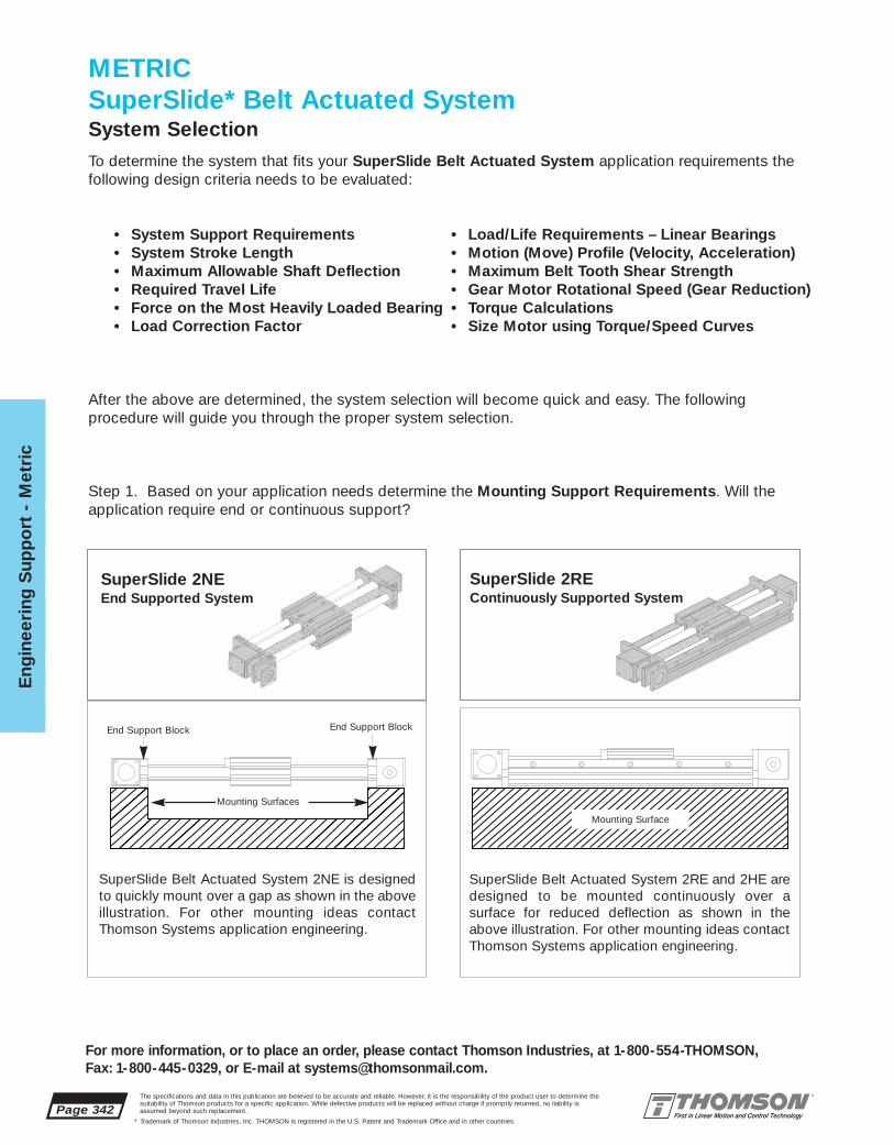
Page 342The specifications and data in this publication are believed to be accurate and reliable. However, it is the responsibility of the product user to determine thesuitability of Thomson products for a specific application. While defective products will be replaced without charge if promptly returned, no liability isassumed beyond such replacement.
* Trademark of Thomson Industries, Inc. THOMSON is registered in the U.S. Patent and Trademark Office and in other countries.
Eng
inee
ring
Sup
po
rt -
Met
ric
For more information, or to place an order, please contact Thomson Industries, at 1-800-554-THOMSON, Fax: 1-800-445-0329, or E-mail at [email protected].
METRICSuperSlide* Belt Actuated SystemSystem Selection
Mounting Surfaces
End Support Block End Support Block
To determine the system that fits your SuperSlide Belt Actuated System application requirements the following design criteria needs to be evaluated:
• System Support Requirements • Load/Life Requirements – Linear Bearings• System Stroke Length • Motion (Move) Profile (Velocity, Acceleration)• Maximum Allowable Shaft Deflection • Maximum Belt Tooth Shear Strength• Required Travel Life • Gear Motor Rotational Speed (Gear Reduction)• Force on the Most Heavily Loaded Bearing • Torque Calculations• Load Correction Factor • Size Motor using Torque/Speed Curves
After the above are determined, the system selection will become quick and easy. The following procedure will guide you through the proper system selection.
Step 1. Based on your application needs determine the Mounting Support Requirements. Will the application require end or continuous support?
Mounting Surface
SuperSlide 2NEEnd Supported System
SuperSlide 2REContinuously Supported System
SuperSlide Belt Actuated System 2NE is designedto quickly mount over a gap as shown in the aboveillustration. For other mounting ideas contactThomson Systems application engineering.
SuperSlide Belt Actuated System 2RE and 2HE aredesigned to be mounted continuously over a surface for reduced deflection as shown in theabove illustration. For other mounting ideas contactThomson Systems application engineering.
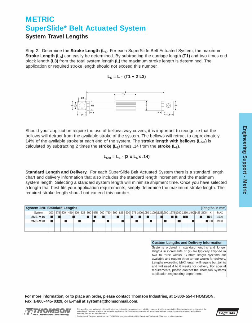
The specifications and data in this publication are believed to be accurate and reliable. However, it is the responsibility of the product user to determine thesuitability of Thomson products for a specific application. While defective products will be replaced without charge if promptly returned, no liability isassumed beyond such replacement.
* Trademark of Thomson Industries, Inc. THOMSON is registered in the U.S. Patent and Trademark Office and in other countries.
Eng
ineering S
upp
ort - M
etric
Page 343
For more information, or to place an order, please contact Thomson Industries, at 1-800-554-THOMSON, Fax: 1-800-445-0329, or E-mail at [email protected].
2NE-M16 ■ ■ ■ ■ ■ ■ ■ ■ ■ ■ ■ ■ ■
2NE-M20 ■ ■ ■ ■ ■ ■ ■ ■ ■ ■
Should your application require the use of bellows way covers, it is important to recognize that the bellows will detract from the available stroke of the system. The bellows will retract to approximately14% of the available stroke at each end of the system. The stroke length with bellows (LS/B) is calculated by subtracting 2 times the stroke (LS) times .14 from the stroke (LS).
LS/B = LS - (2 x LS x .14)
Standard Length and Delivery. For each SuperSlide Belt Actuated System there is a standard lengthchart and delivery information that also includes the standard length increment and the maximum system length. Selecting a standard system length will minimize shipment time. Once you have selecteda length that best fits your application requirements, simply determine the maximum stroke length. Therequired stroke length should not exceed this number.
L
L4
H4
L3
C3
T1
C3 H2 H
L5L3
H4
Custom Lengths and Delivery InformationSystems ordered in standard lengths and longerlengths in increments of (X) are typically shipped intwo to three weeks. Custom length systems are available and require three to four weeks for delivery.Lengths exceeding MAX length will require butt jointsand will need 4 to 6 weeks for delivery. For specialrequirements, please contact the Thomson Systemsapplication engineering department.
Step 2. Determine the Stroke Length (Ls). For each SuperSlide Belt Actuated System, the maximumStroke Length (LS) can easily be determined. By subtracting the carriage length (T1) and two times endblock length (L3) from the total system length (L) the maximum stroke length is determined. The application or required stroke length should not exceed this number.
LS = L - (T1 + 2 L3)
METRICSuperSlide* Belt Actuated SystemSystem Travel Lengths
System 2NE Standard Lengths (Lengths in mm)System 300 375 400 450 500 525 600 675 700 750 800 825 900 975 1000 1050 1100 11251200
■ ■ ■ ■75 1500■ ■ ■ 100 2000
1275 1300 1350 1400 1425 1500 X MAX

Page 344The specifications and data in this publication are believed to be accurate and reliable. Howevsuitability of Thomson products for a specific application. While defective products will be replassumed beyond such replacement.
* Trademark of Thomson Industries, Inc. THOMSON is registered in the U.S. Patent and Tradem
Eng
inee
ring
Sup
po
rt -
Met
ric
For more information, or to place an order, please coFax: 1-800-445-0329, or E-mail at systems@thomson
Step 4. Determine the Required Travel Life (km
Lt= 2 • s • f • Lh • 60
Travel Life
106
100 000
50 000
20 000
10 000
5 000
2 000
1 000
500
200
1000 1 2
System Length (m)
Load
on
Sys
tem
(N)
Maximum Recommended Load on System
2NE-M20
2NE-M16
Step 3. For end supported systems, determine if the system selected meets the Maximum AllowableDeflection criteria.
In end supported applications the bearing system canwithstand a substantial amount of system deflection andstill run smoothly due to the universal self-aligning feature of the Super Smart Ball Bushing* bearing. In aBelt actuated end supported application, deflection islimited by the amount of LinearRace* shaft curvature aBall Bushing bearing can withstand. Step 3 will deter-mine if the system size and length can handle theapplied load with respect to the deflection limit. ForSuperSlide Belt Actuated System 2NE there is a graph(SBM 9) that gives the maximum recommended load onthe system based on LinearRace deflection. To deter-mine the system that best meets your applicationrequirements, simply enter the graph with the total load(including any dynamic loads) on the system and theoverall system length. Select a system characteristiccurve that is above or to the right of the plotted point. To
SuperSlide 2NEEnd Supported System – Horizontal Orientation
Graph (SBM 9)
METRICSuperSlide* Belt Actuated SystemSystem Deflection
determine the actual deflection see the EngineeringSupport Appendix, page 378.
er, it is the responsibility of the product user to determine theaced without charge if promptly returned, no liability is
ark Office and in other countries.
ntact Thomson Industries, at 1-800-554-THOMSON, mail.com.
).
Lt = required travel life (km)s = stroke (mm)f = frequency (cycles/minute)Lh = service life (hrs)
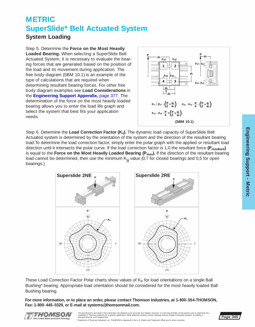
The specifications and data in this publication are believed to be accurate and reliable. However, it is the responsibility of the product user to determine thesuitability of Thomson products for a specific application. While defective products will be replaced without charge if promptly returned, no liability isassumed beyond such replacement.
* Trademark of Thomson Industries, Inc. THOMSON is registered in the U.S. Patent and Trademark Office and in other countries.
Eng
ineering S
upp
ort - M
etric
Page 345
For more information, or to place an order, please contact Thomson Industries, at 1-800-554-THOMSON, Fax: 1-800-445-0329, or E-mail at [email protected].
Step 6. Determine the Load Correction Factor (Kθ). The dynamic load capacity of SuperSlide BeltActuated system is determined by the orientation of the system and the direction of the resultant bearingload.To determine the load correction factor, simply enter the polar graph with the applied or resultant load direction until it intersects the polar curve. If the load correction factor is 1,0 the resultant force (Presultant)is equal to the Force on the Most Heavily Loaded Bearing (Pmax). If the direction of the resultant bearingload cannot be determined, then use the minimum Kθ value (0,7 for closed bearings and 0,5 for openbearings.)
Superslide 2NE
Step 5. Determine the Force on the Most HeavilyLoaded Bearing. When selecting a SuperSlide BeltActuated System, it is necessary to evaluate the bear-ing forces that are generated based on the position ofthe load and its movement during application. Thefree body diagram (SBM 10.1) is an example of thetype of calculations that are required when determining resultant bearing forces. For other freebody diagram examples see Load Considerations inthe Engineering Support Appendix, page 377. The determination of the force on the most heavily loadedbearing allows you to enter the load life graph andselect the system that best fits your applicationneeds.
METRICSuperSlide* Belt Actuated SystemSystem Loading
KθKθ
P P
P Superslide 2REP
1 2
4 3
P P
2
d2
d0
d0
d3
d1
F1z F2z
F1Y, F2Y
F4z
F3Y,
F3z
F4Y
F1Y F4YP2
d3
d1∼ =( (X
F1z F4z P2
P4
d2
d0== ( X+ (
24 d0F2z F3z PP d2== ( (X-
(SBM 10.1)
These Load Correction Factor Polar charts show values of Kθ for load orientations on a single BallBushing* bearing. Appropriate load orientation should be considered for the most heavily loaded BallBushing bearing.
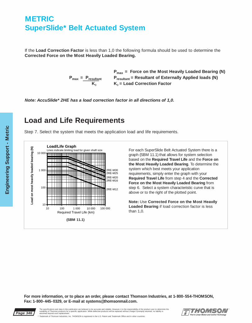
Page 346The specifications and data in this publication are believed to be accurate and reliable. However, it is the responsibility of the product user to determine thesuitability of Thomson products for a specific application. While defective products will be replaced without charge if promptly returned, no liability isassumed beyond such replacement.
* Trademark of Thomson Industries, Inc. THOMSON is registered in the U.S. Patent and Trademark Office and in other countries.
Eng
inee
ring
Sup
po
rt -
Met
ric
For more information, or to place an order, please contact Thomson Industries, at 1-800-554-THOMSON, Fax: 1-800-445-0329, or E-mail at [email protected].
Load/Life GraphLines indicate limiting load for given shaft size
Lo
ad o
n m
ost
hea
vily
load
ed b
eari
ng
(N
)
1010
100
100
1 000
1 000
10 000
10 000
100 000
Required Travel Life (km)
2RE-M16
2RE-M302RE-M25
2RE-M20
2RE-M12
For each SuperSlide Belt Actuated System there is agraph (SBM 11.1) that allows for system selectionbased on the Required Travel Life and the Force onthe Most Heavily Loaded Bearing. To determine thesystem which best meets your application requirements, simply enter the graph with yourRequired Travel Life from step 4 and the CorrectedForce on the Most Heavily Loaded Bearing fromstep 6. Select a system characteristic curve that isabove or to the right of the plotted point.
Note: Use Corrected Force on the Most HeavilyLoaded Bearing if load correction factor is less than 1,0.
Step 7. Select the system that meets the application load and life requirements.
(SBM 11.1)
Load and Life Requirements
If the Load Correction Factor is less than 1,0 the following formula should be used to determine theCorrected Force on the Most Heavily Loaded Bearing.
Pmax = Force on the Most Heavily Loaded Bearing (N)Pmax = Presultant Presultant = Resultant of Externally Applied loads (N)
Ku Ku = Load Correction Factor
Note: AccuSlide* 2HE has a load correction factor in all directions of 1,0.
METRICSuperSlide* Belt Actuated System

The specifications and data in this publication are believed to be accurate and reliable. However, it is the responsibility of the product user to determine thesuitability of Thomson products for a specific application. While defective products will be replaced without charge if promptly returned, no liability isassumed beyond such replacement.
* Trademark of Thomson Industries, Inc. THOMSON is registered in the U.S. Patent and Trademark Office and in other countries.
Eng
ineering S
upp
ort - M
etric
Page 347
For more information, or to place an order, please contact Thomson Industries, at 1-800-554-THOMSON, Fax: 1-800-445-0329, or E-mail at [email protected].
Trapezoidal Motion Profile:
Assume: ta = tc = td = t/3 and xa = xd = x/4, xc = x/2
Then: Vavg = x/tVmax = 1.5 • Vavg
a = -d = Vmax / ta = 4.5x/t2
t = total Move Time (s)ta = acceleration Time (s)tc = time at Constant Velocity (s)td = deceleration Time (s)
Vavg = average Velocity (m/s)Vmax = maximum Velocity (m/s)
METRICSuperSlide* Belt Actuated SystemMotion ProfileA typical linear belt actuated application normally consists of a series of motion profiles. The actuatedtorque required to move the system should be evaluated for each motion profile. There are two basicmotion profile types. The first and most simple move is a triangular motion profile which consists of twolegs. The first leg is for acceleration and the second is for deceleration. The second motion profile type istrapezoidal which consists of an acceleration leg, a leg of constant velocity and a deceleration leg.
Vmax
ta td
Accelerate(Time in seconds)
Decelerate(Time in seconds)
Vmax
ta
Accelerate(Time in seconds)
Decelerate(Time in seconds)
tc td
Constant Velocity(Time in seconds)
Velo
city
Velo
city
Triangular Motion Profile Trapezoidal Motion Profile
Triangular Motion Profile:
Assume: ta = td = t/2 and xa = xd = x/2
Then: Vavg = x/tVmax = 2 • Vavg = 2x/t
a = Vmax / ta = 4 x/t2
Where: a = acceleration (m/s2)d = deceleration (m/s2)x = total Distance (m)
xa = distance to Accelerate (m)xc = distance at Constant Velocity (m)xd = distance to Decelerate (m)
Step 8. Determine the Motion Profile that fits your application requirements. Calculate Vmax and a.
Maximum Belt Tooth Shear Strength
Step 9. Calculate the Total Axial Forces on the system belt and determine whether they are within the limitsof the Belt Pre-Tension Force and Maximum Allowable Tooth Shear of the belt. The Total Axial SystemBelt Force (Ps) is the summation of External Force (Pe), Acceleration Force (Pa) and Frictional Force (Pf).
Ps = Pe + Pa + Pf
Step 9a. Determine the External Axial Forces (Pe). External axial forces seen by the Superslide BeltActuated system can be the result of application forces such as stretching fabric in a textile applicationor compressing boxing in a packaging application. In a vertical application, the external force is the addition of gravity acting on the payload. In those vertical applications the motor must be mountedabove the load on the carriage.

Page 348The specifications and data in this publication are believed to be accurate and reliable. However, it is the responsibility of the product user to determine thesuitability of Thomson products for a specific application. While defective products will be replaced without charge if promptly returned, no liability isassumed beyond such replacement.
* Trademark of Thomson Industries, Inc. THOMSON is registered in the U.S. Patent and Trademark Office and in other countries.
Eng
inee
ring
Sup
po
rt -
Met
ric
For more information, or to place an order, please contact Thomson Industries, at 1-800-554-THOMSON, Fax: 1-800-445-0329, or E-mail at [email protected].
2HE-M10 10 3,9 0,4 0,003 4 0,9 225 4852HE-M20 20 26,5 1,75 0,003 4 7,0 1260 1488
2RE-M12 12 8,8 0,4 0,002 8 0,5 225 4852RE-M16 16 16,7 1,12 0,002 8 0,7 780 817
2NE-M16 16 0,4 0,002 8 0,7 225 4852NE-M20 20 22,6 1,12 0,002 8 1,2 780 817
Step 9b. Determine the Acceleration force (Pa). To overcome the inertia generated by the payload, the carriage assembly and the belt force due to acceleration must be evaluated.
Pa = a • (Wc + Wp + (Wb • L • 2))g
a = Vmax / ta = linear acceleration (m/s2) (from step 8)
Part Nominal Carriage Belt Coefficient Number Seal Belt Pre- MaximumNumber Dia. Weight Weight Friction of Seals Drag Tension Axial Force,
(N) (N/m) Carriage (N) Force (N) Belt (N)
SuperSlide 2NE Belt Actuated System Data
SuperSlide 2NE
Part Nominal Carriage Belt Coefficient Number Seal Belt Pre- MaximumNumber Dia. Weight Weight Friction of Seals Drag Tension Axial Force,
(N) (N/m) Carriage (N) Force (N) Belt (N)
SuperSlide 2RE Belt Actuated System Data
SuperSlide 2RE
Part Nominal Carriage Belt Coefficient Number Seal Belt Pre- MaximumNumber Size Weight Weight Friction of Seals Drag Tension Axial Force,
(N) (N/m) Carriage (N) Force (N) Belt (N)
AccuSlide 2HE Belt Actuated System Data
AccuSlide* 2HE
Step 9c. Determine theFrictional Force (Pf). The totalFrictional force is the sum of thepayload and carriage weighttimes the system coefficient offriction plus the additional sealdrag.
Pf = [ msys• (Wp + Wc) + n • Ds]
Wp= payload weight (N)
Wc= carriage weight (N)(see table at left)
msys= system coefficient of friction (see table at left)
DS= seal Drag (N) (see table at left)
n= number of seals (see table at left)
In the case of vertical axis orientation, this Pf term may beomitted.
Step 9d. Calculate Total AxialSystem Belt Force (Ps):
Ps = Pe + Pa + Pf
METRICSuperSlide* Belt Actuated SystemMaximum Belt Tooth Shear Strength (continued)
= 4.5 • xt2
Vmax = maximum velocity (m/s) (from Step 8)ta = acceleration time (s)xa = distance to accelerate (m)L = overall length of system (m)x = total distance (m)t = total move time (s)
Wc = carriage Weight (N) (from table below)Wp = weight of Payload (N) (from Application Data)Wb = weight of Belt (N/m) (from table below)
g = acceleration due to gravity = 9,81 m/s2

The specifications and data in this publication are believed to be accurate and reliable. However, it is the responsibility of the product user to determine thesuitability of Thomson products for a specific application. While defective products will be replaced without charge if promptly returned, no liability isassumed beyond such replacement.
* Trademark of Thomson Industries, Inc. THOMSON is registered in the U.S. Patent and Trademark Office and in other countries.
Eng
ineering S
upp
ort - M
etric
Page 349
For more information, or to place an order, please contact Thomson Industries, at 1-800-554-THOMSON, Fax: 1-800-445-0329, or E-mail at [email protected].
2RE-M12 12 26,74 84 12 20 3 1:1, 3:1, 5:1, 10:1 4852RE-M16 16 35,01 110 11 32 5 1:1, 3:1, 5:1, 10:1 817
2HE-M10 10 26,74 84 12 20 3 1:1, 3:1, 5:1, 10:1 4852HE-M20 20 47,75 150 12 50 5 1:1, 3:1, 5:1, 10:1 1488
2NE-M16 16 26,74 84 12 20 3 1:1, 3:1, 5:1, 10:1 4852NE-M20 20 35,01 110 11 32 5 1:1, 3:1, 5:1, 10:1 817
Step 9e. Compare the calculated Total Axial System Belt Force (PS) with the Belt Pre-Tension Forcein the tables on the previous page. If the calculated value exceeds the Pre-Tension Force in the tablethen the application parameters or the size of the system should be reconsidered, as the possibilityexists that the belt could go into a slackened condition causing slippage on the pulley. In no caseshould the Total Axial Belt Force (PS) ever exceed the Maximum Axial Force for the belt in the tableson the previous page.
Maximum Belt Tooth Shear CapacityStep 10. It is also important to check that the application parameters are within the limits of the BeltTooth Shear Capacity.
Part Nominal Pitch Circle Lead Number of Belt Belt Standard MaximumNumber Dia. Diameter (mm/rev.) Effective Width Pitch Gear Axial
(mm) Teeth (mm) (mm) Ratios Force (N)
SuperSlide 2NE Belt Actuated System Data
SuperSlide 2NE
Part Nominal Pitch Circle Lead Number of Belt Belt Standard MaximumNumber Size Diameter (mm/rev.) Effective Width Pitch Gear Axial
(mm) Teeth (mm) (mm) Ratios Force (N)
AccuSlide 2HE Belt Actuated System Data
AccuSlide* 2HE
Part Nominal Pitch Circle Lead Number of Belt Belt Standard MaximumNumber Dia. Diameter (mm/rev.) Effective Width Pitch Gear Axial
(mm) Teeth (mm) (mm) Ratios Force (N)
SuperSlide 2RE Belt Actuated System Data
SuperSlide 2RE
METRICSuperSlide* Belt Actuated System
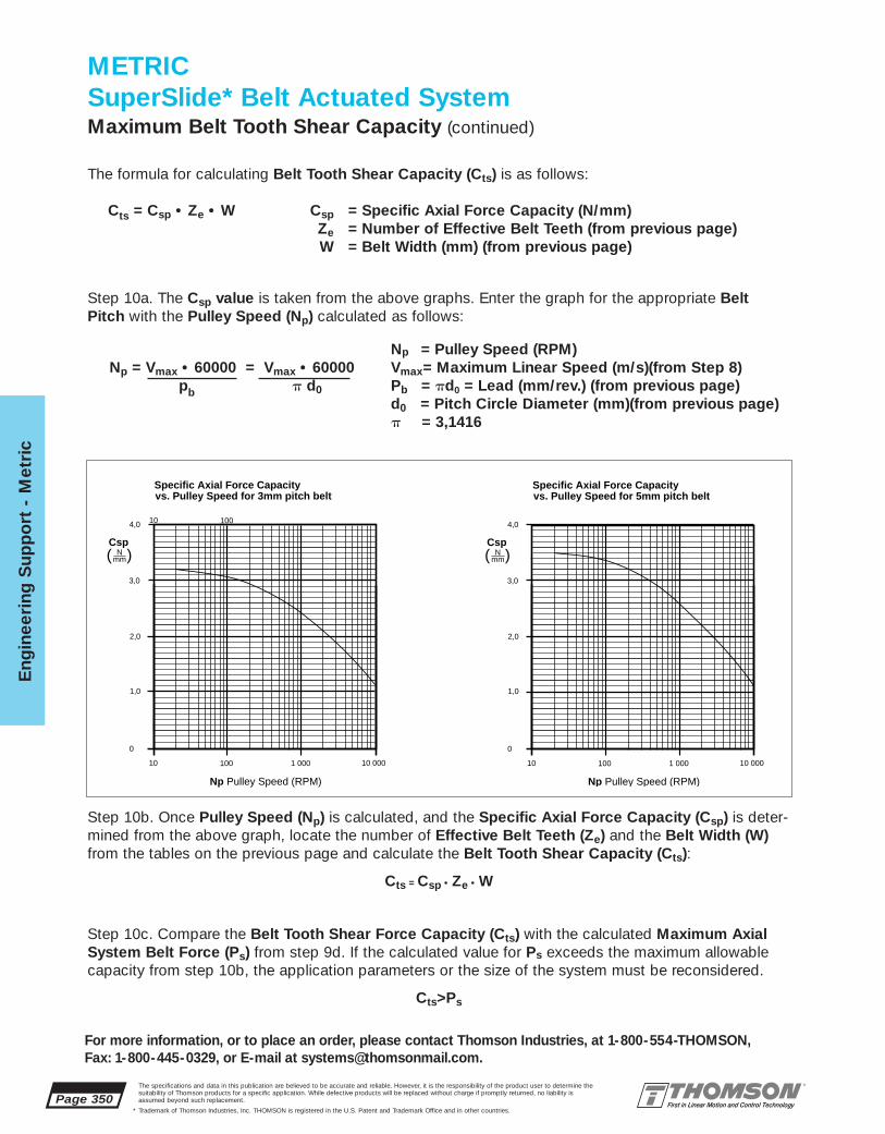
Page 350The specifications and data in this publication are believed to be accurate and reliable. However, it is the responsibility of the product user to determine thesuitability of Thomson products for a specific application. While defective products will be replaced without charge if promptly returned, no liability isassumed beyond such replacement.
* Trademark of Thomson Industries, Inc. THOMSON is registered in the U.S. Patent and Trademark Office and in other countries.
Eng
inee
ring
Sup
po
rt -
Met
ric
For more information, or to place an order, please contact Thomson Industries, at 1-800-554-THOMSON, Fax: 1-800-445-0329, or E-mail at [email protected].
The formula for calculating Belt Tooth Shear Capacity (Cts) is as follows:
Cts = Csp • Ze • W Csp = Specific Axial Force Capacity (N/mm) Ze = Number of Effective Belt Teeth (from previous page)W = Belt Width (mm) (from previous page)
Specific Axial Force Capacityvs. Pulley Speed for 3mm pitch belt
Np Pulley Speed (RPM)
10 100
1,0
1 000 10 000
2,0
3,0
4,0
0
Csp( N )
mm
10 100
Specific Axial Force Capacityvs. Pulley Speed for 5mm pitch belt
Np Pulley Speed (RPM)
10 100
1,0
1 000 10 000
2,0
3,0
4,0
0
Csp( N )
mm
Step 10a. The Csp value is taken from the above graphs. Enter the graph for the appropriate BeltPitch with the Pulley Speed (Np) calculated as follows:
Np = Pulley Speed (RPM)Np = Vmax • 60000 = Vmax • 60000 Vmax= Maximum Linear Speed (m/s)(from Step 8)
pb p d0 Pb = pd0 = Lead (mm/rev.) (from previous page)d0 = Pitch Circle Diameter (mm)(from previous page)p = 3,1416
Step 10b. Once Pulley Speed (Np) is calculated, and the Specific Axial Force Capacity (Csp) is deter-mined from the above graph, locate the number of Effective Belt Teeth (Ze) and the Belt Width (W)from the tables on the previous page and calculate the Belt Tooth Shear Capacity (Cts):
Cts = Csp • Ze • W
Step 10c. Compare the Belt Tooth Shear Force Capacity (Cts) with the calculated Maximum AxialSystem Belt Force (Ps) from step 9d. If the calculated value for Ps exceeds the maximum allowablecapacity from step 10b, the application parameters or the size of the system must be reconsidered.
Cts>Ps
METRICSuperSlide* Belt Actuated SystemMaximum Belt Tooth Shear Capacity (continued)

The specifications and data in this publication are believed to be accurate and reliable. However, it is the responsibility of the product user to determine thesuitability of Thomson products for a specific application. While defective products will be replaced without charge if promptly returned, no liability isassumed beyond such replacement.
* Trademark of Thomson Industries, Inc. THOMSON is registered in the U.S. Patent and Trademark Office and in other countries.
Eng
ineering S
upp
ort - M
etric
Page 351
For more information, or to place an order, please contact Thomson Industries, at 1-800-554-THOMSON, Fax: 1-800-445-0329, or E-mail at [email protected].
2HE-M10 10 26,74 84 NEMA 23 1:1, 3:1, 5:1, 10:12HE-M20 20 47,75 150 NEMA 34 1:1, 3:1, 5:1, 10:1
2NE-M16 16 26,74 84 NEMA 23 1:1, 3:1, 5:1, 10:12NE-M20 20 35,01 110 NEMA 23 1:1, 3:1, 5:1, 10:1
2RE-M12 12 26,74 84 NEMA 23 1:1, 3:1, 5:1, 10:12RE-M16 16 35,01 110 NEMA 23 1:1, 3:1, 5:1, 10:1
Step 11. Determine the Motor Rotational Speed required to move at Vmax for all system ratios.
The SuperSlide Belt Actuated System is equipped with a Thomson Micron True Planetary* PrecisionGearhead already mounted. Each gearhead ratio (greater than 1:1) provides an increase in output torqueand requires the motor to operate at a higher speed.
METRICSuperSlide* Belt Actuated SystemSpeed RequirementsRotational vs. Linear
Part Nominal Pitch Lead Motor StandardNumber Dia. Circle (mm/rev) Frame Gear
Dia. (mm) Size Ratios
SuperSlide 2NE Belt Actuated System Data
SuperSlide 2NE
Part Nominal Pitch Lead Motor StandardNumber Dia. Circle (mm/rev) Frame Gear
Dia. (mm) Size Ratios
SuperSlide 2RE Belt Actuated System Data
SuperSlide 2RE
Part Nominal Pitch Lead Motor StandardNumber Size Circle (mm/rev) Frame Gear
Dia. (mm) Size Ratios
AccuSlide 2HE Belt Actuated System Data
AccuSlide* 2HE
Calculate the Maximum Motor Speed (Nmax) at the system Maximum Linear Speed (Vmax) from Step 8 using the following formula:
Vmax= Maximum Linear Speed (m/s)Nmax = Vmax i i = Gear Ratio
pb d0 = Pitch Circle Diameter (mm) (from tables above)pb = pd0 = Lead (mm/rev.) (from tables above)
or with unit conversions and constants: p= 3,1416
Nmax = Vmax • i • (1000mm/m) • (60 sec/min) = Vmax • i • (19 100) (RPM)pd0 d0

Page 352The specifications and data in this publication are believed to be accurate and reliable. However, it is the responsibility of the product user to determine thesuitability of Thomson products for a specific application. While defective products will be replaced without charge if promptly returned, no liability isassumed beyond such replacement.
* Trademark of Thomson Industries, Inc. THOMSON is registered in the U.S. Patent and Trademark Office and in other countries.
Eng
inee
ring
Sup
po
rt -
Met
ric
For more information, or to place an order, please contact Thomson Industries, at 1-800-554-THOMSON, Fax: 1-800-445-0329, or E-mail at [email protected].
METRICSuperSlide* Belt Actuated SystemTorque Calculations
Step 12. In order to size a motor for your SuperSlide Belt Actuated system it is important to calculate the torque required to meet your application requirements with all of the parameters in mind. If you are actuating your system with a stepping motor, then a maximum or peak torque (Tpeak) calculation isrequired. Peak torque is usually seen at the time of maximum acceleration, however, other factorssuch as torque due to external forces can affect when peak torque occurs. It is important to calculatefor all torque conditions (Torque due to acceleration (TA), Torque at constant velocity (Tcv), Torquedue to deceleration (TD), and Torque required to hold at rest (TH)), and take that torque with thelargest magnitude as the Peak Torque (Tpeak).
TA = TJ + TF + Tg + Te (N • m)Tcv = TF + Tg + Te (N • m)TD = TJ - TF - Tg - Te (N • m)TH = -TF + Tg + Te (N • m)
where: TJ = Torque due to system inertia (N • m)TF = Torque due to friction (N • m)Tg = Torque due to gravity (N • m)Te = Torque due to external forces (N • m)
Should you be actuating your SuperSlide system with a servo motor system then it is also necessaryto calculate a Root-Mean-Square Torque (TRMS) or Continuous Torque.
TRMS = ta ( TA)2 + tcv (Tcv)2 + td (TD)2 + th (TH)2 (N • m)
ta + tcv + td + th
where: ta = time to accelerate (s)tcv = time at constant velocity (s)td = time to decelerate (s)th = time at rest (s)
Step 12a. Calculate Torque due to system inertia (TJ):
TJ = 1000 • 2 • a • Jp + JM • i + Jg • i + TL (N • m)d0 i2 • jg
and
TL = Pa • d0 (N • m)1000 • 2 • i • jg • jb
where: TL = Torque due to payload (N • m)a = required linear acceleration (m/s2) (from step 8)
d0 = pulley pitch circle diameter (mm) (from table on next page)Jp = drive pulley inertia (Kg • m2) (from table on next page)JM = motor inertia (Kg • m2)(1) (g • cm2 = Kg • m2 x 10-7)Jg = gearbox inertia (Kg • m2) (from table on next page)
i = gearbox ratio (from Application Data)jg = gearbox efficiency = 90%jb = belt efficiency = 90%Pa = acceleration force (N)
(1) For motor inertia data see the Motion Control Section, page 431.
]] ]]

Part System Pitch Pulley Carriage BeltNumber Size Circle inertia Weight Weight
Diameter (kg • m2) (N) (N/m)(mm)
The specifications and data in this publication are believed to be accurate and reliable. However, it is the responsibility of the product user to determine thesuitability of Thomson products for a specific application. While defective products will be replaced without charge if promptly returned, no liability isassumed beyond such replacement.
* Trademark of Thomson Industries, Inc. THOMSON is registered in the U.S. Patent and Trademark Office and in other countries.
Eng
ineering S
upp
ort - M
etric
Page 353
For more information, or to place an order, please contact Thomson Industries, at 1-800-554-THOMSON, Fax: 1-800-445-0329, or E-mail at [email protected].
2RE-M12 12 26,74 7,3 x 10⁻⁶ 8,8 0,4
2RE-M16 16 35,01 3,02 x 10⁻⁵ 16,7 1,12
2HE-M10 10 26,74 7,3 x 10⁻⁶ 3,9 0,42HE-M20 20 47,75 1,54x 10⁻⁴ 26,5 1,75
2HE-M10-OZP-A 1:1 NEMA23 NT-23-1 8,14 x 10⁻⁴
2HE-M10-OZP-B 3:1 NEMA23 NT-23-3 7,82 x 10⁻⁴
2HE-M10-OZP-C 5:1 NEMA23 NT-23-5 2,58 x 10⁻⁴
2HE-M10-OZP-D 10:1 NEMA23 NT-23-10 1,61 x 10⁻⁴
2HE-M20-OZP-E 1:1 NEMA34 NT-34-1 4,9 x 10⁻³
2HE-M20-OZP-F 3:1 NEMA34 NT-34-3 4,51 x 10⁻³
2HE-M20-OZP-G 5:1 NEMA34 NT-34-5 1,39 x 10⁻³
2HE-M20-OZP-H 10:1 NEMA34 NT-34-10 7,56 x 10⁻⁴
2RE-M12-OEM-A 1:1 NEMA23 NT-23-1 8,14 x 10⁻⁴
2RE-M12-OEM-B 3:1 NEMA23 NT-23-3 7,82 x 10⁻⁴
2RE-M12-OEM-C 5:1 NEMA23 NT-23-5 2,58 x 10⁻⁴
2RE-M12-OEM-D 10:1 NEMA23 NT-23-10 1,61 x 10⁻⁴
2RE-M16-OEM-A 1:1 NEMA23 NT-23-1 8,14 x 10⁻⁴
2RE-M16-OEM-B 3:1 NEMA23 NT-23-3 7,82 x 10⁻⁴
2RE-M16-OEM-C 5:1 NEMA23 NT-23-5 2,58 x 10⁻⁴
2RE-M16-OEM-D 10:1 NEMA23 NT-23-10 1,61 x 10⁻⁴
2NE-M16-OLL-A 1:1 NEMA23 NT-23-1 8,14 x 10⁻⁴
2NE-M16-OLL-B 3:1 NEMA23 NT-23-3 7,82 x 10⁻⁴
2NE-M16-OLL-C 5:1 NEMA23 NT-23-5 2,58 x 10⁻⁴
2NE-M16-OLL-D 10:1 NEMA23 NT-23-10 1,61 x 10⁻⁴
2NE-M20-OLL-A 1:1 NEMA23 NT-23-1 8,14 x 10⁻⁴
2NE-M20-OLL-B 3:1 NEMA23 NT-23-3 7,82 x 10⁻⁴
2NE-M20-OLL-C 5:1 NEMA23 NT-23-5 2,58 x 10⁻⁴
2NE-M20-OLL-D 10:1 NEMA23 NT-23-10 1,61 x 10⁻⁴
2NE-M16 16 26,74 7,3 x 10⁻⁶ 0,42NE-M20 20 35,01 3,02 x 10⁻⁵ 22,6 1,12
Part System Pitch Pulley Carriage BeltNumber Size Circle inertia Weight Weight
Diameter (kg • m2) (N) (N/m)(mm)
SuperSlide 2NE Belt Actuated System Data
SuperSlide 2NE
SuperSlide 2RE Belt Actuated System Data
SuperSlide 2RE
Part System Pitch Pulley Carriage BeltNumber Size Circle inertia Weight Weight
Diameter (kg • m2) (N) (N/m)(mm)
AccuSlide 2HE Belt Actuated System Data
AccuSlide* 2HE
Calculate acceleration force (Pa) (N)
Pa = a • (Wc + Wp + WB • L • 2) (N)g
Wc = weight of carriage (N) (from table below)Wp= weight of payload (N) (from application data)WB= weight of belt (N/m) (from table below)L= overall system length (m)a= required linear acceleration (m/s2) (from step 8)g= acceleration due to gravity = 9,81 m/s2
SuperSlide 2NESystem Gear Motor Gearbox Gearbox
Part Number Ratio Frame Size Part Number inertia (Kg•m2)
AccuSlide 2HESystem Gear Motor Gearbox Gearbox
Part Number Ratio Frame Size Part Number inertia (Kg•m2)
SuperSlide 2RESystem Gear Motor Gearbox Gearbox
Part Number Ratio Frame Size Part Number inertia (Kg•m2)
METRICSuperSlide* Belt Actuated System

Page 354The specifications and data in this publication are believed to be accurate and reliable. However, it is the responsibility of the product user to determine thesuitability of Thomson products for a specific application. While defective products will be replaced without charge if promptly returned, no liability isassumed beyond such replacement.
* Trademark of Thomson Industries, Inc. THOMSON is registered in the U.S. Patent and Trademark Office and in other countries.
Eng
inee
ring
Sup
po
rt -
Met
ric
For more information, or to place an order, please contact Thomson Industries, at 1-800-554-THOMSON, Fax: 1-800-445-0329, or E-mail at [email protected].
2HE-M10 10 3,9 0,4 0,003 4 0,92HE-M20 20 26,5 1,75 0,003 4 7,0
2RE-M12 12 8,8 0,4 0,002 8 0,52RE-M16 16 16,7 1,12 0,002 8 0,7
2NE-M16 16 0,4 0,002 8 0,72NE-M20 20 22,6 1,12 0,002 8 1,2
Part Nominal Carriage Belt Coefficient Number SealNumber Dia. Weight Weight Friction of Seals Drag
(N) (N/m) Carriage (N)
SuperSlide 2NE Belt Actuated System Data
SuperSlide 2NE
Part Nominal Carriage Belt Coefficient Number SealNumber Dia. Weight Weight Friction of Seals Drag
(N) (N/m) Carriage (N)
SuperSlide 2RE Belt Actuated System Data
SuperSlide 2RE
Part Nominal Carriage Belt Coefficient Number SealNumber Size Weight Weight Friction of Seals Drag
(N) (N/m) Carriage (N)
AccuSlide 2HE Belt Actuated System Data
AccuSlide* 2HE
Calculate Torque due to payload (TL ):
TL = Pa • d0 (N • m)
1000 • 2 • i • jg • jb
Calculate Torque due to system inertia (TJ) :
TJ = 1000 • 2 • a • Jp + JM • i + Jg • i + TL (N • m)d0 i2 • jg
]] ]]
METRICSuperSlide* Belt Actuated System

The specifications and data in this publication are believed to be accurate and reliable. However, it is the responsibility of the product user to determine thesuitability of Thomson products for a specific application. While defective products will be replaced without charge if promptly returned, no liability isassumed beyond such replacement.
* Trademark of Thomson Industries, Inc. THOMSON is registered in the U.S. Patent and Trademark Office and in other countries.
Eng
ineering S
upp
ort - M
etric
Page 355
For more information, or to place an order, please contact Thomson Industries, at 1-800-554-THOMSON, Fax: 1-800-445-0329, or E-mail at [email protected].
Step 12b. Calculate Torque due to Friction (TF) :
TF = d0 •Pf
1000 • 2 i • jg •jb
andPf = (Wp + Wc)) • msys + n • Ds
where: Pf = Force due to Friction (N)Wp = Weight of Payload (N) (from Application Data)Wc = Weight of Carriage (N) (from table on previous page)
msys = Coefficient of friction of carriage (from table on previous page)n = Number of seals (from table on previous page)
Ds = Seal Drag (N) (from table on previous page)d0 = Pulley pitch circle diameter (mm) (from table on page 353)
i = Gearbox ratio (from Application Data)jg = Gearbox efficiency = 90%jb = Belt efficiency = 90%
First calculate Force due to friction (Pf) and with this value calculate Torque due to friction (Tf) usingthe formula, above.
Step 12c. Calculate Torque due to gravity (Tg):
Tg = d0 • Pg (N • m)
1000 • 2 i • jg • jb andPg = (Wp + Wc) SINu (N)
where: Pg = Force due to Gravity (N)Wp = Weight of Payload (N) (from Application Data)Wc = Weight of Carriage (N) (from table on previous page)
u = Angle from horizontal (for horizontal u = 0˚, vertical u = 90˚ forupstroke u = 270° for downstroke)
d0 = Pulley pitch circle diameter (mm) (from table on page 353)i = Gearbox ratio (from Application Data)
jg = Gearbox efficiency = 90%jb = Belt efficiency = 90%
First calculate Force due to gravity (Pg) and with this value calculate Torque due to gravity (Tg) usingthe formula, above.
Step 12d. Calculate Torque due to external forces (Te):
Te = d0 •Pe (N • m)
1000 • 2 i • jg • jb
where: d0 = Pulley pitch circle diameter (mm) (from table on page 353)i = Gearbox ratio (from Application Data)
jg = Gearbox efficiency = 90%jb = Belt efficiency = 90%
]] ]]
]] ]]
]] ]]
METRICSuperSlide* Belt Actuated System
Page 356The specifications and data in this publication are believed to be accurate and reliable. However, it is the responsibility of the product user to determine thesuitability of Thomson products for a specific application. While defective products will be replaced without charge if promptly returned, no liability isassumed beyond such replacement.
* Trademark of Thomson Industries, Inc. THOMSON is registered in the U.S. Patent and Trademark Office and in other countries.
Eng
inee
ring
Sup
po
rt -
Met
ric
For more information, or to place an order, please contact Thomson Industries, at 1-800-554-THOMSON, Fax: 1-800-445-0329, or E-mail at [email protected].
The value of external force(s) (Pe) (N) must be calculated or estimated from the application specifications. Any outside forces that have a component that acts along the axis of the Superslidesystem should be included as an external force (Pe) (N).
With the calculated or estimated value of external force (Pe), the Torque due to external force (Te)can be calculated from the formula on the previous page.
Step 12e. Calculate Peak Torque (Tpeak), the largest of the following:
Torque due to acceleration (TA):
TA = TJ + TF + Tg + Te (N • m)
where: TJ = Torque due to system inertia (N • m) (from step 12a)TF = Torque due to friction (N • m) (from step 12b)Tg = Torque due to gravity (N • m) (from step 12c)Te = Torque due to external forces (N • m) (from step 12d)
Torque at constant velocity (Tcv):
Tcv = TF + Tg + Te (N • m)
Torque due to deceleration (TD):
TD = TJ - TF - Tg - Te (N • m)
Torque required to hold at rest (TH):
TH = -TF + Tg + Te (N • m)
Step 12f. Calculate Root-Mean-Square Torque (TRMS) or Continuous Torque:
TRMS = ta (TA)2 + tcv (Tcv)2 + td (TD)2 + th (TH)2 (N • m)ta + tcv + td + th
where: TA, Tcv, TD, and TH are from step 12e.
ta = time to accelerate (s)tcv = time at constant velocity (s)td = time to decelerate (s)th = time at rest (s)
METRICSuperSlide* Belt Actuated System

The specifications and data in this publication are believed to be accurate and reliable. However, it is the responsibility of the product user to determine thesuitability of Thomson products for a specific application. While defective products will be replaced without charge if promptly returned, no liability isassumed beyond such replacement.
* Trademark of Thomson Industries, Inc. THOMSON is registered in the U.S. Patent and Trademark Office and in other countries.
Eng
ineering S
upp
ort - M
etric
Page 357
For more information, or to place an order, please contact Thomson Industries, at 1-800-554-THOMSON, Fax: 1-800-445-0329, or E-mail at [email protected].
Graph SBSM22.1
Motor Speed vs. Torque Curve
Graph SBSM22.1 is an example of a Speedvs. Torque curve for a NEMA 23 motor fromthe Motion Control section. BLX Seriesmotors are available in standard NEMA framesizes 23, 34 and 42 and can be combinedwith either a one, two, three or four axis controller. To determine the motor speed vs.torque curve that best suits the applicationand for a continuation of features and specifications refer to the Motion Control section, page 381.
Motor RPM = Vmax • 60 • i(PB/1000)
where: Vmax = maximum linear speed (m/s) (from step 8)i = gearhead ratio (from Application Data)
PB = belt lead (mm)(from table in step 10)
METRICSuperSlide* Belt Actuated SystemSpeed vs Torque
Step 13. Determine the proper motor selection. Plot Peak Torque (Tpeak) against the Required MotorSpeed from step 11 and enter the Motor Speed vs. Torque graph. (See the Motion Control Section,page 381). If the plotted point is below the curve for intermittent duty, then you have made a properselection. Now plot Continuous Torque (TRMS) against the Required Motor Speed from step 11 andenter the graph again. If the plotted point is below the curve for continuous duty, then you have made aproper selection. If either of the plotted points fall above their respective curve then either a larger framemotor or a different gear ratio gearbox must be employed. Check mounting flange availability whenincreasing the motor frame size. Use of a system with a gearbox with a different gear ratio entails recalculating steps 11 and 12 with the new gear ratio in mind.
To determine motor speed, use the following formula:
APx-232A-D010-Lxx
0
2
4
6
8
10
12
14
16
0 1000 2000 3000 4000 5000 6000
rpm
in-l
b

TNUT-01-M3 7 4 1,75 1,25 3 M3TNUT-02-M4 9,5 5,5 2,25 1,75 4 M4TNUT-03-M4 12 7 2,5 2,5 5 M4TNUT-03-M5 12 7 2,5 2,5 5 M5TNUT-04-M4 16,5 7,9 4,8 1,2 6 M4TNUT-04-M5 M5TNUT-04-M6 M6TNUT-05-M4 19,5 9,8 5,8 2,8 8,6 M4TNUT-05-M5 M5TNUT-05-M6 M6TNUT-05-M8 M8
Page 358The specifications and data in this publication are believed to be accurate and reliable. However, it is the responsibility of the product user to determine thesuitability of Thomson products for a specific application. While defective products will be replaced without charge if promptly returned, no liability isassumed beyond such replacement.
* Trademark of Thomson Industries, Inc. THOMSON is registered in the U.S. Patent and Trademark Office and in other countries.
Eng
inee
ring
Sup
po
rt -
Met
ric
For more information, or to place an order, please contact Thomson Industries, at 1-800-554-THOMSON, Fax: 1-800-445-0329, or E-mail at [email protected].
METRICSuperSlide* Belt Actuated SystemSystem Mounting
Figure 2: Mounting from above using T-slotsor from above through mounting holes.
Figure 1: Mounting from below using T-slotsor from above through mounting holes.
The SuperSlide Belt Actuated System can be mounted using the T-nuts and T-slots from above with clamping fixtures and below as shown below. In addition, SuperSlide Belt Actuated System can alsobe mounted using the bolt down attachment holes found in each end block (System 2NE) or system support base (System 2RE). For other mounting fixity contact Thomson Systems Application Engineering.
SuperSlide 2RESuperSlide 2NE
B
EC
D
F
A
45o
Standard T-Nut Dimensions
T-Nuts for Mounting
Standard T-Nut Dimensions (Dimensions in mm)Part Number A B C D E F

Eng
ineering S
upp
ort - M
etric
Page 359
For more information, or to place an order, please contact Thomson Industries, at 1-800-554-THOMSON, Fax: 1-800-445-0329, or E-mail at [email protected].
The specifications and data in this publication are believed to be accurate and reliable. However, it is the responsibility of the product user to determine thesuitability of Thomson products for a specific application. While defective products will be replaced without charge if promptly returned, no liability isassumed beyond such replacement.
* Trademark of Thomson Industries, Inc. THOMSON is registered in the U.S. Patent and Trademark Office and in other countries.
METRICTurbo Module* Belt Actuated SystemSystem Selection
MountingSurface
MountingSurface
End Supported System Continuously Supported System
To determine the Turbo Module Belt Actuated System that best fits the application requirements the following design criteria should be evaluated:
Note: For multi-axis application mounting and specifications contact the Thomson Systems Application Engineering Department
Min:1mm
Note: Only the systemlength (L) should besupported. The TurboModule end blocks arenot designed to carry the system load andshould be mounted with clearance.
LEnd Block End Block
Turbo Module Belt Actuated System 2GE can be mounted at each end as shown above in gantry or incantilevered configurations. Stiffness of the mounting base and allowable deflection in the application should be considered. For other mounting ideas contact Thomson Systems application engineering.
Turbo Module Belt Actuated System 2GE isdesigned to be mounted continuously over a surfacefor reduced deflection as shown in the above illustration. For other mounting ideas contactThomson Systems application engineering.
Mounting Surface
• System Support Requirements• System Stroke Length• Maximum Allowable System Deflection• Required Travel Life• Force on the Most Heavily Loaded Bearing• Load/Life Requirements – Linear Bearings
• Motion (Move) Profile (Velocity, Acceleration)• Maximum Belt Tooth Shear Strength• Gear Motor Rotational Speed (Gear
Reduction)• Torque Calculations• Size Motor using Torque/Speed Curves
Step 1. Based on your application needs determine the Mounting Support Requirements. Will the application require end or continuous support?

Page 360
Eng
inee
ring
Sup
po
rt -
Met
ric
For more information, or to place an order, please contact Thomson Industries, at 1-800-554-THOMSON, Fax: 1-800-445-0329, or E-mail at [email protected].
The specifications and data in this publication are believed to be accurate and reliable. However, it is the responsibility of the product user to determine thesuitability of Thomson products for a specific application. While defective products will be replaced without charge if promptly returned, no liability isassumed beyond such replacement.
* Trademark of Thomson Industries, Inc. THOMSON is registered in the U.S. Patent and Trademark Office and in other countries.
System 410 530 610 650 770 890 930 1010 1090 1130 1250 X Max.2GE-M25 ■ ■ ■ ■ ■ ■ ■ ■ 120 40102GE-M35 ■ ■ ■ ■ ■ 160 3970
H3
L3 L
T1
L4
Standard Length and Delivery. For each Turbo Module Belt Actuated System there is a standardlength chart and delivery information that also includes the standard length increment and the maximum system length. Selecting a standard system length will minimize shipment time. Once youhave selected a length that best fits your application requirements, simply determine the Maximumstroke length. The required stroke length should not exceed this number.
METRICTurbo Module* Belt Actuated SystemSystem Travel Lengths
Step 2. Determine the Maximum Stroke Length. For each Turbo Module Belt Actuated System, theMaximum Stroke Length can easily be determined. By subtracting the carriage length (T1) from thetotal system length (L) the maximum stroke length is determined. The application or required strokelength should not exceed this number.
System 2GE Standard Lengths (L) (Lengths in mm)
Custom Lengths and Delivery InformationSystems ordered in standard lengths and longerlengths in increments of (X) are typically shipped intwo to three weeks. Custom length systems areavailable and require three to four weeks for delivery.For special requirements, please contact theThomson Systems application engineering department.

Eng
ineering S
upp
ort - M
etric
Page 361
For more information, or to place an order, please contact Thomson Industries, at 1-800-554-THOMSON, Fax: 1-800-445-0329, or E-mail at [email protected].
The specifications and data in this publication are believed to be accurate and reliable. However, it is the responsibility of the product user to determine thesuitability of Thomson products for a specific application. While defective products will be replaced without charge if promptly returned, no liability isassumed beyond such replacement.
* Trademark of Thomson Industries, Inc. THOMSON is registered in the U.S. Patent and Trademark Office and in other countries.
2GE-M15 152GE-M25 25 5.76 X 10⁶ 8.23 X 10⁶ 3.97 X 10¹¹ 5.67 X 10¹¹ 0,186 93,2 20,62GE-M35 35 2.84 X 10⁷ 3.73 X 10⁷ 1.96 X 10¹² 2.57 X 10¹² 0,353 270,6 109,8
Part Nominal Moment of Inertia Stiffness Unit Weight Weight of Weight ofNumber Size Motor End Support End
Ixx Iyy EIxx EIyy W Block Assy. Block Assy.(mm4) (mm4) (N•mm2) (N•mm2) (N/mm) (N) (N)
L
δ
Load
PL/2
x
L
a
Load
P
δ
x
METRICTurbo Module* Belt Actuated SystemSystem Deflection
Step 3. Determine the Turbo Module System Deflection. The Turbo Module 2GE is designed for themost stringent motion control requirements. Due to its unique structure, the Turbo Module can bemounted on simple or cantilevered supports. To maximize system reliability maximum system deflec-tion should be considered in any simply supported application. Calculate deflection (d) using one ofthe following formulae for the appropriate system support condition:
Turbo Module 2GE Belt Actuated System Data
Turbo Module 2GE
Step 3a. The end or simply supported case – deflection at center.
Step 3b. The cantilevered case – deflection at end.
d = Px3+
5Wx4
48EI 384EIP = Load on System (N)
x = Distance between supports (mm)
EI= Stiffness (from table below) (N • mm2)
W = Weight per Unit Length (N/mm)
d = Px3+
Wa4
3EI 8EIP = Load on System (N)
x = Distance between center of gravity of load to support (mm)
EI= Stiffness (from table below) (N • mm2)
W = Weight per Unit Length (N/mm)
a = Unsupported length of base (mm)
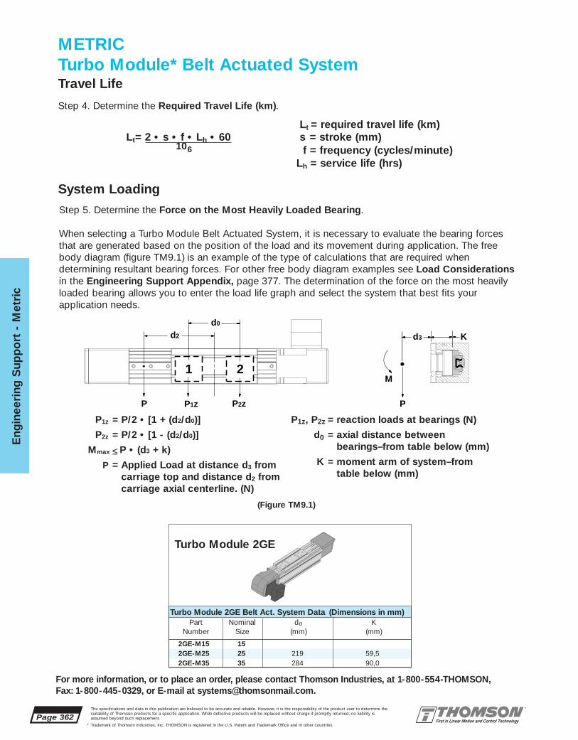
Page 362
Eng
inee
ring
Sup
po
rt -
Met
ric
For more information, or to place an order, please contact Thomson Industries, at 1-800-554-THOMSON, Fax: 1-800-445-0329, or E-mail at [email protected].
The specifications and data in this publication are believed to be accurate and reliable. However, it is the responsibility of the product user to determine thesuitability of Thomson products for a specific application. While defective products will be replaced without charge if promptly returned, no liability isassumed beyond such replacement.
* Trademark of Thomson Industries, Inc. THOMSON is registered in the U.S. Patent and Trademark Office and in other countries.
2GE-M15 152GE-M25 25 219 59,52GE-M35 35 284 90,0
P2zP1zP
d3
P
M
K
1 2
d2
d0
Step 5. Determine the Force on the Most Heavily Loaded Bearing.
When selecting a Turbo Module Belt Actuated System, it is necessary to evaluate the bearing forcesthat are generated based on the position of the load and its movement during application. The freebody diagram (figure TM9.1) is an example of the type of calculations that are required when determining resultant bearing forces. For other free body diagram examples see Load Considerationsin the Engineering Support Appendix, page 377. The determination of the force on the most heavilyloaded bearing allows you to enter the load life graph and select the system that best fits yourapplication needs.
Step 4. Determine the Required Travel Life (km).
Lt = required travel life (km)Lt= 2 • s • f • Lh • 60 s = stroke (mm)
f = frequency (cycles/minute)Lh = service life (hrs)
106
METRICTurbo Module* Belt Actuated SystemTravel Life
System Loading
Part Nominal do KNumber Size (mm) (mm)
Turbo Module 2GE Belt Act. System Data (Dimensions in mm)
Turbo Module 2GE
P1z, P2z = reaction loads at bearings (N)
d0 = axial distance between bearings–from table below (mm)
K = moment arm of system–fromtable below (mm)
P1z = P/2 • [1 + (d2/d0)]
P2z = P/2 • [1 - (d2/d0)]
Mmax ≤ P • (d3 + k)
P = Applied Load at distance d3 from carriage top and distance d2 fromcarriage axial centerline. (N)
(Figure TM9.1)

Eng
ineering S
upp
ort - M
etric
Page 363
For more information, or to place an order, please contact Thomson Industries, at 1-800-554-THOMSON, Fax: 1-800-445-0329, or E-mail at [email protected].
The specifications and data in this publication are believed to be accurate and reliable. However, it is the responsibility of the product user to determine thesuitability of Thomson products for a specific application. While defective products will be replaced without charge if promptly returned, no liability isassumed beyond such replacement.
* Trademark of Thomson Industries, Inc. THOMSON is registered in the U.S. Patent and Trademark Office and in other countries.
Motion ProfileA typical linear belt actuated application normally consists of a series of motion profiles. The drivetorque required to move the system should be evaluated for each motion profile. There are two basicmotion profile types. The first and most simple move is a triangular motion profile which consists of twolegs. The first leg is for acceleration and the second is for deceleration. The second motion profile typeis trapezoidal which consists of an acceleration leg, a leg of constant velocity and a deceleration leg.
Step 7. Determine the Motion Profile that fits your application requirements. Calculate Vmax and a.
Vmax
ta td
Accelerate(Time in seconds)
Decelerate(Time in seconds)
ta
Accelerate(Time in seconds)
td
Decelerate(Time in seconds)
tc
Constant Velocity(Time in seconds)
Velo
city
Velo
city
Triangular Motion Profile Trapezoidal Motion Profile
For each Turbo Module Belt Actuated Systemthere is a graph (figure TM10.2) that allowsfor system selection based on the RequiredTravel Life and the Force on the MostHeavily Loaded Bearing. To determine thesystem which best meets your applicationrequirements, simply enter the graph withyour required travel life from step 4 and theload on the most heavily loaded bearing fromstep 5. Select a system with a characteristiccurve that is above or to the right of the plotted point.
Step 6. Selecting the system that meets load and life requirements.
Load/Life GraphLines indicate limiting load for given shaft size
Lo
ad o
n m
ost
hea
vily
load
ed b
eari
ng
(N
)
10100
100
1 000
1 000
10 000
10 000
100 000
100 000
Required Travel Life (km)
2GE-25
2GE-35
(Figure TM 10.2)
Trapezoidal Motion Profile:
Assume: ta = tc = td = t/3 and xa = xd = x/4, xc = x/2
Then: Vavg = x/tVmax = 1.5 • Vavg
a = -d = Vmax / ta = 4.5x/t2
t = tTotal Move Time (s)ta = acceleration Time (s)tc = time at Constant Velocity (s)td = deceleration Time (s)
Vavg = average Velocity (m/s)Vmax = maximum Velocity (m/s)
Triangular Motion Profile:
Assume: ta = td = t/2 and xa = xd = x/2
Then: Vavg = x/tVmax = 2 • Vavg = 2x/t
a = Vmax / ta = 4 x/t2
Where: a = acceleration (m/s2)d = deceleration (m/s2)x = total Distance (m)
xa = distance to Accelerate (m)xc = distance at Constant Velocity (m)xd = distance to Decelerate (m)
Vmax
METRICTurbo Module* Belt Actuated SystemLoad and Life Requirements

Page 364
Eng
inee
ring
Sup
po
rt -
Met
ric
The specifications and data in this publication are believed to be accurate and reliable. However, it is the responsibility of the product user to determine thesuitability of Thomson products for a specific application. While defective products will be replaced without charge if promptly returned, no liability isassumed beyond such replacement.
* Trademark of Thomson Industries, Inc. THOMSON is registered in the U.S. Patent and Trademark Office and in other countries.
2GE-M15 15 0,003 2,8 22GE-M25 25 42,07 2,75 0,003 7,5 2 2250 33072GE-M35 35 122,58 7,80 0,003 18,0 2 5400 9234
For more information, or to place an order, please contact Thomson Industries, at 1-800-554-THOMSON, Fax: 1-800-445-0329, or E-mail at [email protected].
Part Nominal Carriage Belt Carriage Seal Number Belt Pre MaximumNumber Size Weight Weight Friction Drag of Tension Axial Force,
(N) (N/m) Coefficient (N) Seals Force (N) Belt (N)
Turbo Module 2GE Belt Actuated System Data
Turbo Module 2GE
METRICTurbo Module* Belt Actuated SystemMaximum Belt Tooth Shear Strength
Step 8. Calculate the Total Axial Forces on the system belt and determine whether they are within the limitsof the Belt Pre-Tension Force and Maximum Allowable Tooth Shear of the belt. The Total Axial SystemBelt Force (Ps) is the summation of External Force (Pe), Acceleration Force (Pa), and Frictional Force (Pf).
Ps = Pe + Pa + Pf
Step 8a. Determine the External Axial Forces (Pe). External axial forces seen by the Turbo Module Belt Actuated system can be the result of application forces such as stretching fabric in a textile application or compressing boxing in a packaging application. In a vertical application, the external force is the addition of gravity acting on the payload. In those vertical applications the motor must be mounted above the load on the carriage.
Step 8c. Determine the Frictional Force (Pf). The total Frictional force is the sum of the payload andcarriage mass times the system coefficient of friction plus the additional seal drag.
Pf = [ msys • (Wp + Wc ) + n • Ds ]
Wp = payload weight (N) (from Application Data)
Wc = carriage weight (N) (see table above)msys= system coefficient of friction (see table above)
Step 8d. Calculate Total Axial System Belt Force (Ps): Ps = Pe + Pa + Pf
Step 8e. Compare the calculated Total Axial System Belt Force (Ps) with the Belt Pre-Tension Forcein the tables above. If the calculated value exceeds the Pre-Tension Force in the table then the appli-cation parameters or the size of the system should be reconsidered, as the possibility exists that thebelt could go into a slackened condition causing slippage on the pulley. In no case should the TotalAxial Belt Force (PS) ever exceed the Maximum Axial Force for the belt in the tables above.
DS = seal Drag (N) (see table above)n= number of seals (see table above)
Step 8b. Determine the Acceleration force (Pa). To overcome the inertia generated by the payload, the carriage assembly and the belt force due to acceleration must be evaluated.
Pa = a • (Wc + Wp + (Wb • L • 2))g
a = Vmax / ta = linear acceleration (m/s2) (from step 7)= 4.5 • xt2
Vmax = maximum velocity (m/s) (from Step 8)ta = acceleration time (s)xa = distance to accelerate (m)L = overall length of system (m)x = total distance (m)t = total time (s)
Wc = carriage Weight (N) Wp = Weight of Payload (N)Wb = Weight of Belt (N/m)
g = acceleration due to gravity = 9,81 m/s2
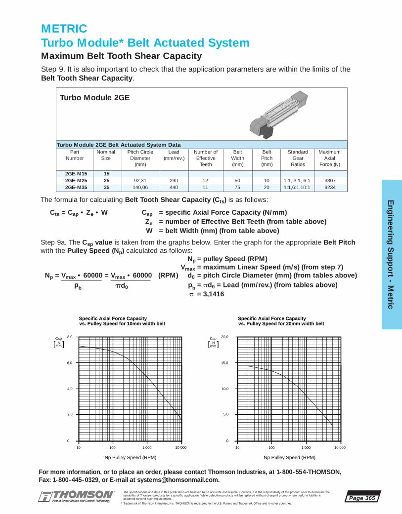
Eng
ineering S
upp
ort - M
etric
Page 365
For more information, or to place an order, please contact Thomson Industries, at 1-800-554-THOMSON, Fax: 1-800-445-0329, or E-mail at [email protected].
The specifications and data in this publication are believed to be accurate and reliable. However, it is the responsibility of the product user to determine thesuitability of Thomson products for a specific application. While defective products will be replaced without charge if promptly returned, no liability isassumed beyond such replacement.
* Trademark of Thomson Industries, Inc. THOMSON is registered in the U.S. Patent and Trademark Office and in other countries.
2GE-M15 152GE-M25 25 92,31 290 12 50 10 1:1, 3:1, 6:1 33072GE-M35 35 140,06 440 11 75 20 1:1,6:1,10:1 9234
Step 9. It is also important to check that the application parameters are within the limits of theBelt Tooth Shear Capacity.
Part Nominal Pitch Circle Lead Number of Belt Belt Standard MaximumNumber Size Diameter (mm/rev.) Effective Width Pitch Gear Axial
(mm) Teeth (mm) (mm) Ratios Force (N)
Turbo Module 2GE Belt Actuated System Data
Turbo Module 2GE
METRICTurbo Module* Belt Actuated SystemMaximum Belt Tooth Shear Capacity
Step 9a. The Csp value is taken from the graphs below. Enter the graph for the appropriate Belt Pitchwith the Pulley Speed (Np) calculated as follows:
Np = pulley Speed (RPM)Vmax = maximum Linear Speed (m/s) (from step 7)
Np = Vmax • 60000 = Vmax • 60000 (RPM) d0 = pitch Circle Diameter (mm) (from tables above)pb pd0 pb = pd0 = Lead (mm/rev.) (from tables above)
p = 3,1416
Specific Axial Force Capacityvs. Pulley Speed for 10mm width belt
Np Pulley Speed (RPM)
10 100
2,0
1 000 10 000
4,0
6,0
8,0
0
Csp
[ N ]
mm
Specific Axial Force Capacityvs. Pulley Speed for 20mm width belt
Np Pulley Speed (RPM)
10 100
5,0
1 000 10 000
10,0
15,0
20,0
0
Csp
[ N ]
mm
The formula for calculating Belt Tooth Shear Capacity (Cts) is as follows:
Cts = Csp • Ze • W Csp = specific Axial Force Capacity (N/mm) Ze = number of Effective Belt Teeth (from table above)W = belt Width (mm) (from table above)

Page 366
Eng
inee
ring
Sup
po
rt -
Met
ric
For more information, or to place an order, please contact Thomson Industries, at 1-800-554-THOMSON, Fax: 1-800-445-0329, or E-mail at [email protected].
The specifications and data in this publication are believed to be accurate and reliable. However, it is the responsibility of the product user to determine thesuitability of Thomson products for a specific application. While defective products will be replaced without charge if promptly returned, no liability isassumed beyond such replacement.
* Trademark of Thomson Industries, Inc. THOMSON is registered in the U.S. Patent and Trademark Office and in other countries.
2GE-M15 152GE-M25 25 92,31 290 1:1, 3:1, 6:12GE-M35 35 140,06 440 1:1, 6:1,10:1
Step 9b. Once Pulley Speed (Np) is calculated, and the Specific Axial Force Capacity (Csp) is determined from the graph on the previous page, locate the number of Effective Belt Teeth (Ze) and theBelt Width (W) from the tables on the previous page and calculate the Belt Tooth Shear Capacity (Cts):
Cts = Csp • Ze • W
Step 9c. Compare the Belt Tooth Shear Force Capacity (Cts) with the calculated Total Axial SystemBelt Force (Ps) from step 8e. If the calculated value exceeds the maximum allowable capacitiy fromstep 9c, the application parameters or the size of the system must be reconsidered.
Cts>Ps
Step 10. Determine the Motor Rotational Speed required to move at Vmax for all system ratios.
The Turbo Module Belt Actuated System is equipped with an AccuTRUE* Planetary Precision Gearheadalready mounted. Each gearhead ratio (greater than 1:1) provides an increase in output torque andrequires the motor to operate at a higher speed.
Speed RequirementsRotational vs. Linear
Calculate the Maximum Motor Speed (Nmax) at the system Maximum Linear Speed (Vmax) from Step 7. using the following formula:
Vmax = Maximum Linear Speed (m/s)Nmax = Vmax i i = Gear Ratio(input/output)
pb d0 = Pitch Circle Diameter (mm) (from table above)pb = pd0 = Lead (mm/rev.) (from table above)
or with unit conversions and constants: p = 3,1416
Nmax = Vmax • i • (1000mm/m) • (60 sec/min) = Vmax • i • (19 100) (RPM)pd0 d0
Part Nominal Pitch Lead StandardNumber Size Circle (mm/rev) Gear
Dia. (mm) Ratios
Turbo Module 2GE Belt Actuated System Data
Turbo Module 2GE
METRICTurbo Module* Belt Actuated System

Eng
ineering S
upp
ort - M
etric
Page 367
For more information, or to place an order, please contact Thomson Industries, at 1-800-554-THOMSON, Fax: 1-800-445-0329, or E-mail at [email protected].
The specifications and data in this publication are believed to be accurate and reliable. However, it is the responsibility of the product user to determine thesuitability of Thomson products for a specific application. While defective products will be replaced without charge if promptly returned, no liability isassumed beyond such replacement.
* Trademark of Thomson Industries, Inc. THOMSON is registered in the U.S. Patent and Trademark Office and in other countries.
METRICTurbo Module* Belt Actuated SystemTorque Calculations
Step 11. In order to size a motor for your Turbo Module Belt Actuated system it is important to calcu-late the torque required to meet your application requirements with all of the parameters in mind. A maximum or peak torque (Tpeak) calculation is required. Peak torque is usually seen at the time ofmaximum acceleration, however, other factors such as torque due to external forces can affect whenpeak torque occurs. It is important to calculate for all torque conditions (Torque due to acceleration(TA), Torque at constant velocity (Tcv), Torque due to deceleration (TD), and Torque required tohold at rest (TH)), and take that torque with the largest magnitude as the Peak Torque (Tpeak).
TA = TJ + TF + Tg + Te (N • m)Tcv = TF + Tg + Te (N • m)TD = TJ - TF - Tg - Te (N • m)TH = -TF + Tg + Te (N • m)
where: TJ = Torque due to system inertia (N • m)TF = Torque due to friction (N • m)Tg = Torque due to gravity (N • m)Te = Torque due to external forces (N • m)
It is also necessary to calculate a Root-Mean-Square Torque (TRMS) or Continuous Torque.
TRMS = ta ( TA)2 + tcv (Tcv)2 + td (TD)2 + th (TH)2 (N • m)
ta + tcv + td + th
where: ta = time to accelerate (s)tcv = time at constant velocity (s)td = time to decelerate (s)th = time at rest (s)
Step 11a. Calculate Torque due to system inertia (TJ):
TJ = 1000 • 2 • a • Jp + JM • i + Jg • i + TL (N • m)d0 i2 • jg
and
TL = Pa • d0 (N • m)1000 • 2 • i • jg • jb
where: TL = torque due to payload (N •m)a = required linear acceleration (m/s2) (from step 7)
d0 = pulley pitch circle diameter (mm) (from table on next page)Jp = drive pulley inertia (Kg • m2) (from table on next page)JM = motor inertia (Kg • m2)(1) (g • cm2 x 10-6 = Kg • m2)Jg = gearbox inertia (Kg • m2) (from table on next page)
i = gearbox ratio (from Application Data)jg = gearbox efficiency = 90%jb = belt efficiency = 90%Pa = acceleration force (N)
(1) For motor inertia data refer to technical information for your MotionControl System, page 431.
]] ]]

Page 368
Eng
inee
ring
Sup
po
rt -
Met
ric
For more information, or to place an order, please contact Thomson Industries, at 1-800-554-THOMSON, Fax: 1-800-445-0329, or E-mail at [email protected].
The specifications and data in this publication are believed to be accurate and reliable. However, it is the responsibility of the product user to determine thesuitability of Thomson products for a specific application. While defective products will be replaced without charge if promptly returned, no liability isassumed beyond such replacement.
* Trademark of Thomson Industries, Inc. THOMSON is registered in the U.S. Patent and Trademark Office and in other countries.
2GE-M15 152GE-M25 25 92,31 2,18 x 10⁻³ 42,07 2,752GE-M35 35 140,06 1,94 x 10⁻² 122,58 7,80
2GE-M25-OQN-K 1:1 AT-10-1 7,0 x 10⁻²
2GE-M25-OQN-L 3:1 AT-10-3 2,34 x 10⁻³
2GE-M25-OQN-M 6:1 AT-10-6 1,00 x 10⁻³
2GE-M35-OQN-N 1:1 AT-14-1 1,99 x 10⁻¹
2GE-M35-OQN-P 6:1 AT-14-6 3,43 x 10⁻³
2GE-M35-OQN-Q 10:1 AT-14-10 2,55 x 10⁻³
Part System Pitch Circle Pulley Inertia Carriage BeltNumber Size Dia. (mm) (kg • m2) Weight (N) Weight (N/m)
Turbo Module 2GE Belt Actuated System Data
Turbo Module 2GE System Gear Gearbox GearboxPart Number Ratio Part Number inertia (Kg • m2)
Turbo Module 2GE Gearbox Data
Calculate acceleration force (Pa) (N)
Pa = a • (Wc + Wp + WB • L • 2) (N)g
Wc = weight of carriage (N) (from table on next page)Wp = weight of payload (N) (from application data)WB = weight of belt (N/m) (from table on next page)
L = overall system length (m)a = required linear acceleration (m/s2)g = acceleration due to gravity = 9,81 m/s2
Calculate Torque due to payload (TL):
TL = Pa • d0 (N • m)
1000 • 2 • i • jg • jb
Calculate Torque due to system inertia (TJ) :
TJ = 1000 • 2 • a • Jp + JM • i + Jg • i + TL (N • m)d0 i2 • jg
Step 11b. Calculate Torque due to Friction (TF) :
TF = d0 •Pf
1000 • 2 i • jg • jb
andPf = (Wp + Wc)) • msys + n • Ds
where: Pf = force due to Friction (N)Wp = weight of Payload (N) (from Application Data)Wc = weight of Carriage (N) (from table on next page)
msys = coefficient of friction of carriage (from table on next page)n = number of seals (from table on next page)
Ds = seal Drag (N) (from table on next page)d0 = pulley pitch circle diameter (mm) (from table on next page)
i = gearbox ratio (from Application Data)jg = gearbox efficiency = 90%jb = belt efficiency = 90%
First calculate Force due to friction (Pf) and with this value calculate Torque due to friction (Tf) usingthe formula, above.
]] ]]
]] ]]
METRICTurbo Module* Belt Actuated System

Eng
ineering S
upp
ort - M
etric
Page 369The specifications and data in this publication are believed to be accurate and reliable. However, it is the responsibility of the product user to determine thesuitability of Thomson products for a specific application. While defective products will be replaced without charge if promptly returned, no liability isassumed beyond such replacement.
* Trademark of Thomson Industries, Inc. THOMSON is registered in the U.S. Patent and Trademark Office and in other countries.
2GE-M15 152GE-M25 25 42,07 2,75 0,003 2 7,52GE-M35 35 122,58 7,80 0,003 2 18
For more information, or to place an order, please contact Thomson Industries, at 1-800-554-THOMSON, Fax: 1-800-445-0329, or E-mail at [email protected].
Part Nominal Carriage Belt Coefficient Number SealNumber Size Weight Weight Friction of Seals Drag
(N) (N/m) Carriage (N)
Turbo Module 2GE Belt Actuated System Data
Turbo Module 2GE
Step 11c. Calculate Torque due to gravity (Tg):
Tg = d0 • Pg (N • m)1000 • 2 i • jg • jb
andPg = (Wp + Wc) SINu (N)
where: Pg = Force due to Gravity (N)Wp = Weight of Payload (N) (from Application Data)Wc = Weight of Carriage (N) (from table above)
u = Angle from horizontal (for horizontal u = 0˚, vertical u = 90˚ forupstroke u = 270° for downstroke
d0 = Pulley pitch circle diameter (mm) (from table on previous page)i = Gearbox ratio (from Application Data)
jg = Gearbox efficiency = 90%jb = Belt efficiency = 90%
First calculate Force due to gravity (Pg) and with this value calculate Torque due to gravity (Tg) usingthe formula, above.
Step 11d. Calculate Torque due to external forces (Te):
Te = d0 •Pe (N • m)
1000 • 2 i • jg • jb
where: d0 = Pulley pitch circle diameter (mm) (from table on previous page)i = Gearbox ratio (from Application Data)
jg = Gearbox efficiency = 90%jb = Belt efficiency = 90%
The value of external force(s) (Pe) (N) must be calculated or estimated from the application specifications.Any outside forces that have a component that acts along the axis of the Turbo Module system shouldbe included as an external force (Pe) (N).
With the calculated or estimated value of external force (Pe), the Torque due to external forces (Te)can be calculated from the formula above.
Step 11e. Calculate Peak Torque (Tpeak), the largest of the following:
Torque due to acceleration (TA):TA = TJ + TF + Tg + Te (N • m)
where: TJ = Torque due to system inertia (N • m) (from step 11a)TF = Torque due to friction (N • m) (from step 11b)Tg = Torque due to gravity (N • m) (from step 11c)Te = Torque due to external forces (N • m) (from step 11d)
]] ]]
]] ]]
METRICTurbo Module* Belt Actuated System
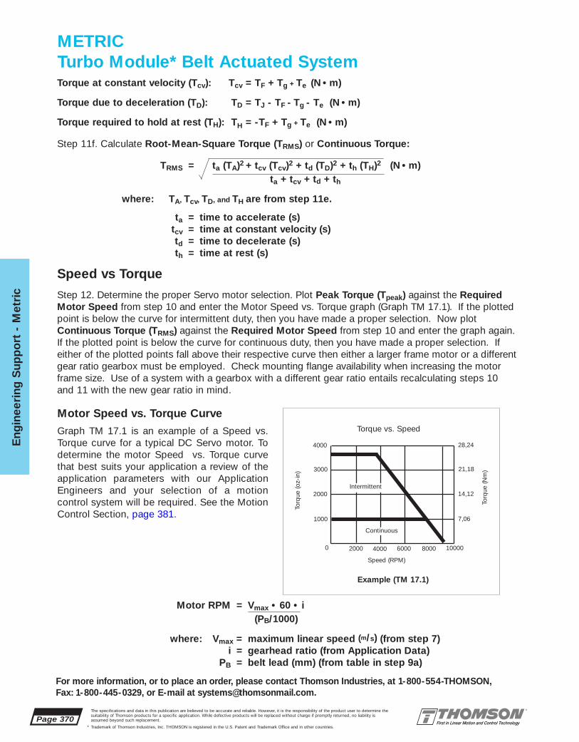
Page 370
Eng
inee
ring
Sup
po
rt -
Met
ric
For more information, or to place an order, please contact Thomson Industries, at 1-800-554-THOMSON, Fax: 1-800-445-0329, or E-mail at [email protected].
The specifications and data in this publication are believed to be accurate and reliable. However, it is the responsibility of the product user to determine thesuitability of Thomson products for a specific application. While defective products will be replaced without charge if promptly returned, no liability isassumed beyond such replacement.
* Trademark of Thomson Industries, Inc. THOMSON is registered in the U.S. Patent and Trademark Office and in other countries.
Motor Speed vs. Torque Curve
Graph TM 17.1 is an example of a Speed vs.Torque curve for a typical DC Servo motor. Todetermine the motor Speed vs. Torque curvethat best suits your application a review of theapplication parameters with our ApplicationEngineers and your selection of a motion control system will be required. See the MotionControl Section, page 381.
4000
3000
2000
1000
0 2000 4000 6000 8000
Torque vs. Speed
Torq
ue (o
z-in
)
Speed (RPM)
Example (TM 17.1)
Continuous
Intermittent
10000
Torq
ue (N
m)
28,24
21,18
14,12
7,06
Torque at constant velocity (Tcv): Tcv = TF + Tg + Te (N • m)
Torque due to deceleration (TD): TD = TJ - TF - Tg - Te (N • m)
Torque required to hold at rest (TH): TH = -TF + Tg + Te (N • m)
Step 11f. Calculate Root-Mean-Square Torque (TRMS) or Continuous Torque:
TRMS = ta (TA)2 + tcv (Tcv)2 + td (TD)2 + th (TH)2 (N • m)ta + tcv + td + th
where: TA, Tcv, TD, and TH are from step 11e.
ta = time to accelerate (s)tcv = time at constant velocity (s)td = time to decelerate (s)th = time at rest (s)
Motor RPM = Vmax • 60 • i(PB/1000)
where: Vmax = maximum linear speed (m/s) (from step 7)i = gearhead ratio (from Application Data)
PB = belt lead (mm) (from table in step 9a)
Speed vs Torque
Step 12. Determine the proper Servo motor selection. Plot Peak Torque (Tpeak) against the RequiredMotor Speed from step 10 and enter the Motor Speed vs. Torque graph (Graph TM 17.1). If the plottedpoint is below the curve for intermittent duty, then you have made a proper selection. Now plotContinuous Torque (TRMS) against the Required Motor Speed from step 10 and enter the graph again.If the plotted point is below the curve for continuous duty, then you have made a proper selection. Ifeither of the plotted points fall above their respective curve then either a larger frame motor or a differentgear ratio gearbox must be employed. Check mounting flange availability when increasing the motorframe size. Use of a system with a gearbox with a different gear ratio entails recalculating steps 10and 11 with the new gear ratio in mind.
METRICTurbo Module* Belt Actuated System

Eng
ineering S
upp
ort A
pp
endix
Page 371
For more information, or to place an order, please contact Thomson Industries, at 1-800-554-THOMSON, Fax: 1-800-445-0329, or E-mail at [email protected].
The specifications and data in this publication are believed to be accurate and reliable. However, it is the responsibility of the product user to determine thesuitability of Thomson products for a specific application. While defective products will be replaced without charge if promptly returned, no liability isassumed beyond such replacement.
* Trademark of Thomson Industries, Inc. THOMSON is registered in the U.S. Patent and Trademark Office and in other countries.
Engineering Support Appendix
Evaluating your needs and providing you with the information to make the system selection that’s right for you.
Thomson Linear Motion Systems have been designed to fit a broad spectrum oflinear motion applications. From light to heavy loads from short stroke to nearlyinfinite length from modular to completely integrated units, our Systems are built tomeet your needs. Unactuated or actuated with ball screws or belts in both inchand metric sizes, we provide a complete solution to your Linear Motion requirements.
This support section includes the basic engineering data and formulae to determine deflection, load-life relationships, free body diagrams, and materialspecifications needed to select the proper system for your design needs.
Each section of the catalog is preceded with a concise selection section designedto be a road map to your Linear Motion Solution. Each section concludes with anApplication Analysis required for a proper system selection. Simply fax yourApplication Analysis to Thomson Application Engineering at 1-516-883-9039 andreceive quick, accurate answers to your selection questions.

Page 372
Eng
inee
ring
Sup
po
rt A
pp
end
ix
The specifications and data in this publication are believed to be accurate and reliable. However, it is the responsibility of the product user to determine thesuitability of Thomson products for a specific application. While defective products will be replaced without charge if promptly returned, no liability isassumed beyond such replacement.
* Trademark of Thomson Industries, Inc. THOMSON is registered in the U.S. Patent and Trademark Office and in other countries.
Many variables influence the selection of a Linear MotionSystem. The best solutiondemands a thorough evaluation ofthe design application. Only thencan the design criteria be established.
The following basic design criteria should be considered whenselecting a linear motion system:• system support requirements• system stroke length• system deflection• envelope limitations• system load capacity• actuator load capacity• speed and acceleration• drive requirements• accuracy and repeatability• environment
If your application has specialrequirements, they should beadded to the list of criteria.
Calculating Bearing and InnerRace SizeThe factors which influence bear-ing size are maximum load on asingle bearing and total travellife. Calculating stroke length andduty cycle will provide an accuratetravel life requirement.
Applied load and travel life arerelated through the following formula:
Life = (C/F)3 x 107 (in) = (C/F)3 x 250 (km)
where:c = dynamic load rating of the
Super Smart Ball bushing* bearing
F = applied load
Thomson Super Smart Ball bush-ing bearings will provide 10 millioninches or 250 km of travel life attheir rated load capacities, andextended life under reduced load.
The load/life graphprovides a quickevaluation of bear-ing performancebased on maximumload on a singlebearing and travellife requirements.
To determine yourbearing/inner racesize, plot your maxi-mum load on themost heavily loadedbearing and requiredtravel life. If theplotted point occursabove a bearing performancecurve, specify the next largest sizeSystem.
It is also important to keep in mindthat the orientation of load caneffect the load carrying capacity ofthe Ball Bushing bearing. For thisreason polar graphs are providedin each system selection section.The force on the must heavilyloaded bearing used in theLoad/Life graph should be thequotient of the resultant appliedload and the Kθ value from thepolar graph.
Determining Stroke, SystemLength, Envelope.A primary consideration for yourapplication will be the maximumstroke required. Each ThomsonSystem dimension chart lists theformula for maximum stroke and apre-calculated summation of com-ponents which limit the stroke.
Maximum Stroke Length is determined by subtracting the carriage length (T1 or T2) and 2times the end support block length(L3), where necessary, from thetotal system length (L). For sys-tems requiring protective bellows,consult the appropriate selectionsection for stroke reduction for-mulae. Thomson systems are supplied in a variety of standardlengths which vary with Systemtype and size. A standard lengthchart has been provided whichaccompanies each System’s technical data. Standard lengthsrequire shorter lead times and aremore economical.
Custom lengths are available inmost linear motion systems. Careful consideration and evalua-tion of design criteria should occurbefore specifying a custom lengthSystem. Contact the ThomsonSystems application engineeringdepartment for assistance inaddressing custom requirements.
Engineering Support
Choosing A Thomson Linear Motion System
Kθ
F
P
SuperSlide 2RB
Load/Life GraphLines indicate limiting load for given shaft size
Lo
ad o
n m
ost
hea
vily
load
ed b
eari
ng
(N
)
1010
100
100
1 000
1 000
10 000
10 000
100 000
Required Travel Life (km)
2RB-M16
2RB-M302RB-M25
2RB-M20
2RB-M12

Eng
ineering S
upp
ort A
pp
endix
Page 373
For more information, or to place an order, please contact Thomson Industries, at 1-800-554-THOMSON, Fax: 1-800-445-0329, or E-mail at [email protected].
The specifications and data in this publication are believed to be accurate and reliable. However, it is the responsibility of the product user to determine thesuitability of Thomson products for a specific application. While defective products will be replaced without charge if promptly returned, no liability isassumed beyond such replacement.
® Teflon is a registered trademark of E.I. DuPont de Nemours & Company.* Trademark of Thomson Industries, Inc. THOMSON is registered in the U.S. Patent and Trademark Office and in other countries.
Thomson Linear Motion Systemsare pre-lubricated with a rust pre-ventative oil. This process isdesigned to inhibit the corrosion ofthe steel components within thesystem during transport.
Available upon special request,LinearLube* lubricant can beapplied to the ball tracks of theBall Bushing* bearings. This specially formulated lubricant provides optimum performance formost applications. LinearLube is asynthetic lubricant utilizing sus-pended Teflon® in a specially formulated base compound.
LinearLube provides excellent performance characteristics in awide range of applications. It isFDA listed, non-polluting, non-corrosive. LinearLube will not stainand adheres tightly to parts, form-ing a water resistant barrier andairtight seal against contaminant’s.
LinearLube reduces overall maintenance and extends serviceintervals, which helps decreaseyour maintenance costs.
• Maintains properties in operating temperatures from -65˚F to 450˚F
• U.S.D.A. Rated H1 (Non-Toxic)• Inhibits wear, rust, and
corrosion• Will not oxidize in use• 100% water resistant
*LinearLube is an NLGI Grade II class materialwhich contains PTFE (Teflon®) particles suspend-ed in a specially compounded base.
All Thomson Ball Bushing bearingsrequire a small amount of greaseor oil to operate. For mostapplications, lubricant is recom-mended to prevent wearing andrusting of the bearing surfaces.When linear speeds are high, alight oil should be used and thebearing should be prevented fromrunning dry for a prolonged periodof time.
A medium to heavy oil or lightgrease has greater adhesion properties that afford longer bearing protection and minimizesealing problems. The numerousbuilt-in pockets in the Ball Bushingbearing retainer allow grease to bestored for an extended period oftime. Though not generally recom-mended, in some lightly loaded, low speed and highly contaminat-ed applications, Ball Bushing bearings have been used withoutlubrication. For these types ofapplications contact Thomsonapplication engineering.
Specifying a Thomson linearmotion system.Thomson linear motion systemsare specified quickly and easilywith a single part number. Whenyou have evaluated your linearmotion requirements and selecteda System which best meets yourcriteria, review the System part
number, System length, and anyspecial options to generate a single order number.
Custom lengths or special require-ments should be reviewed with theThomson systems applicationengineering department.
System ReplacementComponentsReplacement components formsystems are available fromThomson. Assure the accuracyand repeatability of your system byspecifying a -XS after the compo-nent part number.
Thomson Linear Motion systemsare designed and manufacturedthrough advanced processes withhigh grade materials chosen fortheir strength, durability, and hard-ness. The following is a compre-hensive list of the materials utilizedthroughout Thomson systems.
Engineering Support
Lubrication, Materials and Part Number Specifications
Ball Bushing BearingComponents MaterialSuper Smart Ball Bushing* bearings• Sleeve and Retainers Thomson Engineered Plastic††• Bearing Plates Hardened Bearing Steel• Balls Chrome Alloy Steel• Seals Synthetic RubberPillow Block Housing Aluminum Alloy†Supports• Type ASB End Support Aluminum Alloy†• Type SB End Support Iron• Type SRA Rail Support Aluminum Alloy†• Twin Shaft End Support Aluminum Alloy†• Twin Shaft Web End Support Aluminum Alloy†• Integrated End Support Aluminum Alloy†• Dual Shaft Support Rail Aluminum Alloy†Inner Race (60 Case™ Shafting) Case Hardened High Carbon SteelCarriage• Universal Carriage Aluminum Alloy†• Twin Shaft Carriage Aluminum Alloy†• Twin Shaft Web Carriage Aluminum Alloy†• Modular Dual Shaft Carriage Aluminum Alloy†• Integrated Dual Shaft Carriage Aluminum Alloy††Custom Black Anodized for inch size systems ††Limited to a Max. Temperature of 185˚F (85˚C)
Custom Grey Anodized for metric size systemsCustom system lengths may require black paint to protect machine cut-off ends on Dual shaft RailAssemblies and Shaft support Rails. If a specific surface finish is required contact the ThomsonSystems application engineering department.

Page 374
Eng
inee
ring
Sup
po
rt A
pp
end
ix
For more information, or to place an order, please contact Thomson Industries, at 1-800-554-THOMSON, Fax: 1-800-445-0329, or E-mail at [email protected].
The specifications and data in this publication are believed to be accurate and reliable. However, it is the responsibility of the product user to determine thesuitability of Thomson products for a specific application. While defective products will be replaced without charge if promptly returned, no liability isassumed beyond such replacement.
* Trademark of Thomson Industries, Inc. THOMSON is registered in the U.S. Patent and Trademark Office and in other countries.
Coefficient of FrictionThe coefficient of friction of Thomson Ball Bushing*bearings ranges from 0.001 to 0.004. There are twocomponents of the coefficient of friction, the rolling oroperating friction and the static or breakaway friction.
Coefficient of Rolling FrictionThe rolling coefficient of friction is measured by theforce required to operate the Ball Bushing at a con-stant rate of travel. The formula for determining fric-tional resistance during operation is as follows:
Pf = P x fr
where: Pf =Frictional resistance (lbf)P =Resultant of externally applied loads (lbf)fr =Coefficient of rolling friction
The following table describes the coefficient of rollingfriction of Ball Bushing bearings operating onThomson 60 Case* LinearRace*. These values aregrouped according to the number of ball circuits ineach bearing. Friction coefficients are constant amongbearings having three and four ball circuits, but slightlyless for bearings with five or six ball circuits. A dryBall Bushing bearing has the lowest coefficient of fric-tion due to the complete absence of lubricant surfacetension effects. Values for grease lubrication rangesfrom 100% greater in the smaller sizes to 20% to50% greater in the larger sizes. Oil lubrication
(medium/heavy, viscosity 64 cs @ 100˚F) achieves frictional values slightly higher than those for greaselubrication.
Coefficient of Static Friction
The coefficient of static or breakaway friction is measured by the force required to initiate Ball Bushingbearing movement. The formula used to determinestatic frictional resistance is:
Pf = P x fo
where: fo = Coefficient of static friction
The values for the coefficient of static friction or break-away friction are not measurably affected by the number of ball circuits in the bearing or by the lubrication condition.
Seal Drag Another variable that affects the frictional resistance ina Ball Bushing bearing system is seal drag. Whenseals are used to retain lubricant or to prevent entry offoreign particles, frictional resistance must be takeninto account for determining total frictional drag. Inapplications where contamination is minimal, the sealscan be removed to reduce frictional drag. In highlycontaminated applications, seals, wipers and or scrap-ers are used to minimize the ingress of contaminationinto the bearing. This protective measure adds to thefrictional drag of the bearing system. There is a fineline between minimizing frictional drag and maximizingcontaminant protection which is controlled by theaddition or removal of seals, wipers or scrapers. Inapplications that require low frictional drag in highlycontaminated environments, contact Thomson application engineering.
Engineering Support
Part Number Specifications
2RE-M16-OEM-A- L800
System Lengthfor inch sizes in inchesfor metric sizes in mm
Type of Ball Screw,Type of Lead Screw, orType of Gearbox
Type of Carriage
Type of Linear Race Support
System Basic Prefix
"M" signifies Metric Size
Shaft Diameter or SystemSize for inch: 1/16 inch incrementsi.e. size 12 = 3/4 inch dia.for metric: size is the dia. in mm
Type of Bearing Block
Coefficient of Friction and Seal Drag
Bearing Number Condition Load in % of Rolling Load RatingI.D. of Ball of (for 2,000,000 inches of travel)
Circuits Lubrication 125% 100% 75% 50% 25%
The following is anexplanation of the partnumbering system:
125% 100% 75% 50% 25%.0028 .0030 .0033 .0036 .0040
Ball bushing Bearing coefficients of static friction (f0)Load in % of Rolling Load Rating
Ball bushing Bearing coefficients of rolling friction (fr)
1/4”, 3/8” No Lube .0011 .0011 .0012 .0016 .00251/2”, 5/8” 3 & 4 Grease Lube .0019 .0021 .0024 .0029 .0044
8 mm Oil Lube .0022 .0023 .0027 .0032 .00453/4”, 1” No Lube .0011 .0011 .0012 .0024 .003312, 16 mm 5 Grease Lube .0018 .0019 .0021 .0024 .0033
Oil Lube .0020 .0021 .0023 .0027 .003611/4” No Lube .0011 .0011 .0012 .0014 .0019thru 4” 6 Grease Lube .0016 .0016 .0017 .0018 .0022
20 thru 40 mm Oil Lube .0011 .0011 .0012 .0013 .00185/8” thru No Lube .0011 .0011 .0012 .0013 .001911/2” 10 Grease Lube .0014 .0014 .0015 .0016 .0019
12 thru 40 mm Oil Lube .0016 .0016 .0017 .0019 .0025

Eng
ineering S
upp
ort A
pp
endix
Page 375
For more information, or to place an order, please contact Thomson Industries, at 1-800-554-THOMSON, Fax: 1-800-445-0329, or E-mail at [email protected].
The specifications and data in this publication are believed to be accurate and reliable. However, it is the responsibility of the product user to determine thesuitability of Thomson products for a specific application. While defective products will be replaced without charge if promptly returned, no liability isassumed beyond such replacement.
* Trademark of Thomson Industries, Inc. THOMSON is registered in the U.S. Patent and Trademark Office and in other countries.
Engineering Support
Super Smart Ball Bushing Bearing
The new Super Smart Ball Bushing* bearing representsa major advancement in linear bearing technologyworldwide. The Super Smart Ball Bushing bearingoffers twice the load capacity or eight times the travellife of the industry standard Thomson Super BallBushing bearing. An enormous technological break-through, considering the Super Ball Bushing Bearingalready offers three times the load capacity or twenty-seven times the travel life of conventional linear bearings.
Technologically Advanced Design
The load carrying component of the Super Smart BallBushing bearing is the combination four hardened andprecision ground, bearing quality steel components(Figures 1 & 2).
The first component is the steel outer ring, whichallows the bearing to maintain its diametrical fit-upeven when installed in a housing that is slightly out-of-round. The unique ring design also allows for bearingadjustment and the removal of diametrical clearance.The second component is the precision ground doubletrack bearing plate that provides twice the load capacity and features universal self-alignment.
The third component is the rolling element. EachSuper Smart Ball Bushing utilizes precision groundballs manufactured to the highest quality standards forroundness and sphericity. The result is maximum loadcapacity, travel life and performance.
The last component is the 60 Case* LinearRace* thatacts as the inner race to the Super Smart Ball BushingBearing. Each 60 Case LinearRace is manufactured tothe highest quality standards for roundness, straight-ness, surface finish and hardness. Roundness is heldunder eighty millionths of an inch (2µm); straightnessto .002 inches per foot (0,050mm per 0,3m); surfacefinish under twelve microinch and hardness between60-65 HRC. The combination of inner and outer raceor 60 Case LinearRace and Super Smart Ball Bushingbearing provides the basis for the RoundRailAdvantage.
The RoundRail Advantage
The RoundRail Advantage is the inherent ability ofSuper Smart Ball Bushing bearing system to accom-modate torsional misalignment (caused by inaccura-cies in carriage or base machining or by machinedeflection) with little increase in stress to bearing com-ponents. Installation time and cost are minimized andsystem performance is maximized.
HardenedPrecision Ring
Double TrackBearing Plate
HardenedPrecision Ring
Double TrackBearing Plate
Retainer
Figure 1
Figure 2
Cut-away view of the Super Smart Ball Bushing Bearing
Cross-section of Super SmartBall Bushing Bearing

Page 376
Eng
inee
ring
Sup
po
rt A
pp
end
ix
The specifications and data in this publication are believed to be accurate and reliable. However, it is the responsibility of the product user to determine thesuitability of Thomson products for a specific application. While defective products will be replaced without charge if promptly returned, no liability isassumed beyond such replacement.
* Trademark of Thomson Industries, Inc. THOMSON is registered in the U.S. Patent and Trademark Office and in other countries.
For more information, or to place an order, please contact Thomson Industries, at 1-800-554-THOMSON, Fax: 1-800-445-0329, or E-mail at [email protected].
Engineering Support
Super Smart Ball Bushing Bearing
Universal Self-Alignment
The bearing plate of the Super Smart Ball Bushing*Bearing is designed with many unique and technologi-cally advanced features. The Universal Self-Alignment feature assures that the Super Smart Ball BushingBearing will achieve maximum performance regardingload capacity, travel life, smooth operation and coeffi-cient of friction. The three components that make upuniversal self-alignment are Rock, Roll and Yaw.
Rock
The bearing plate is designed to rock 0.5˚ about thehardened precision ground outer ring (Figures 3 & 4).This self-aligning feature allows the Super Smart BallBushing bearing to absorb misalignment caused byinaccuracies in housing bore alignment or 60 CaseLinearRace deflection.
This rocking capability provides smooth entry and exitof the precision balls into and out of the load zoneassuring a constant low coefficient of friction. By compensation for misalignment, each bearing ball inthe load carrying area is uniformly loaded providingmaximum load capacity.
Roll
The second key design feature of the Super Smart BallBushing bearing plate is its ability to Roll. The bearingplate is designed with the radius of its outer surfacesmaller than the inside radius of the precision outerring (Figure 5). This allows the bearing plate to compensate for torsional misalignment and evenly distribute the load on each of its two ball tracks. Theroll component assures maximum load capacity andtravel life.
Yaw
The shape formed by the Rock and Roll featuresallows the Super Smart Ball Bushing bearing plate torotate about its center (Figure 6). This allows theSuper Smart Ball Bushing bearing to absorb skewcaused by misalignment. The result is a constant low coefficient of friction and maximum bearing performance.
LOAD
Hardened Precision Ring
Double Lip Wiper
0.5o
Figure 5
Figure 3
Figure 6
Figure 4
Close-up of double track bearing plates showinghow they self-align (roll) to evenly distribute
the load on each of their two ball tracks.
Bearing plates rotate about their center to preventskewing relative to the 60 Case LinearRace.
Close-up of hardened precision ring, showing how the bearing plate self-aligns (rocks) about
the curved surface of the ring.
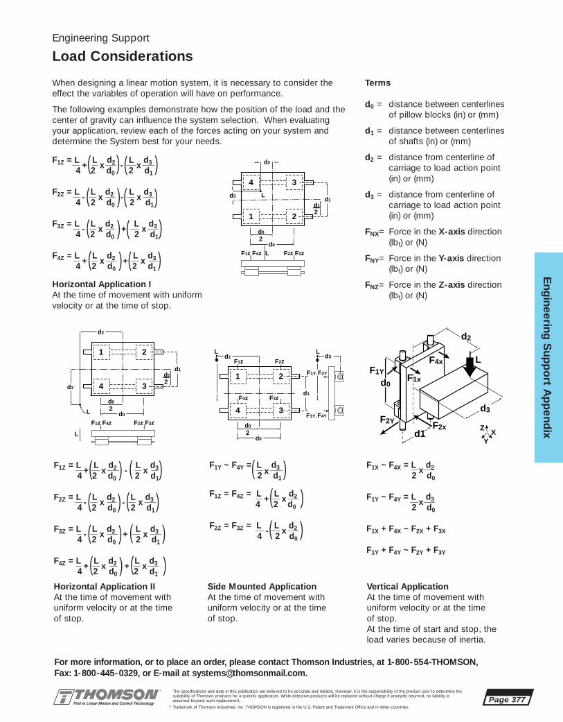
Eng
ineering S
upp
ort A
pp
endix
Page 377
For more information, or to place an order, please contact Thomson Industries, at 1-800-554-THOMSON, Fax: 1-800-445-0329, or E-mail at [email protected].
The specifications and data in this publication are believed to be accurate and reliable. However, it is the responsibility of the product user to determine thesuitability of Thomson products for a specific application. While defective products will be replaced without charge if promptly returned, no liability isassumed beyond such replacement.
* Trademark of Thomson Industries, Inc. THOMSON is registered in the U.S. Patent and Trademark Office and in other countries.
F1Z = L +
Lx
d2 -L
x d3
4 2 d0 2 d1
F2Z = L -
Lx
d2 -L
x d3
4 2 d0 2 d1
F3Z = L -
Lx
d2 +L
x d3
4 2 d0 2 d1
F4Z = L +
Lx
d2 +L
x d3
4 2 d0 2 d1
( ( ( (
( ( ( (
( ( ( (
( ( ( (
Engineering Support
Load Considerations
When designing a linear motion system, it is necessary to consider theeffect the variables of operation will have on performance.
The following examples demonstrate how the position of the load and thecenter of gravity can influence the system selection. When evaluatingyour application, review each of the forces acting on your system anddetermine the System best for your needs.
Terms
d0 = distance between centerlines of pillow blocks (in) or (mm)
d1 = distance between centerlines of shafts (in) or (mm)
d2 = distance from centerline of carriage to load action point (in) or (mm)
d3 = distance from centerline of carriage to load action point (in) or (mm)
FNX= Force in the X-axis direction(lbf) or (N)
FNY= Force in the Y-axis direction (lbf) or (N)
FNZ= Force in the Z-axis direction (lbf) or (N)
Horizontal Application IAt the time of movement with uniformvelocity or at the time of stop.
Horizontal Application IIAt the time of movement with uniform velocity or at the time of stop.
Side Mounted ApplicationAt the time of movement with uniform velocity or at the time of stop.
Vertical ApplicationAt the time of movement with uniform velocity or at the time of stop.At the time of start and stop, theload varies because of inertia.
F1Z = L +
Lx
d2 -L
x d3
4 2 d0 2 d1
F2Z = L -
Lx
d2 -L
x d3
4 2 d0 2 d1
F3Z = L -
Lx
d2 +L
x d3
4 2 d0 2 d1
F4Z = L +
Lx
d2 +L
x d3
4 2 d0 2 d1
1 2
4 3
L
L
2
d2
d0
d0
d1
F1z F4z F2z F3z
d32d1
4 3
1 2
L
L
2
d2
d0
d0
d1
F1z F4z F2z F3z
d3
2d1
1 2
4 3
L L
2
d2
d0
d0
d3
d1
F1z F2z
F1Y, F2Y
F4z
F3Y,
F3z
F4Y
d1F2x
F2Y
d0
d2
F1xF1Y
F4x
d3
L
Z
YX
F1Y ~ F4Y = L x
d32 d1
F1Z = F4Z = L +
L x
d24 2 d0
F2Z = F3Z = L -
L x
d24 2 d0
F1X ~ F4X = L x
d22 d0
F1Y ~ F4Y = L x
d32 d0
F1X + F4X ~ F2X + F3X
F1Y + F4Y ~ F2Y + F3Y
( ( ( (
( (( (
( ( ( (
( ( ( (( (
( (
( (

Page 378
Eng
inee
ring
Sup
po
rt A
pp
end
ix
For more information, or to place an order, please contact Thomson Industries, at 1-800-554-THOMSON, Fax: 1-800-445-0329, or E-mail at [email protected].
The specifications and data in this publication are believed to be accurate and reliable. However, it is the responsibility of the product user to determine thesuitability of Thomson products for a specific application. While defective products will be replaced without charge if promptly returned, no liability isassumed beyond such replacement.
* Trademark of Thomson Industries, Inc. THOMSON is registered in the U.S. Patent and Trademark Office and in other countries.
When a Linear Motion System isused in an end supported con-figuration it is important to ensurethat system deflections at thebearing locations are kept within performance limitations.
These equations give the deflection at the center of an endsupported system. Systems withcontinuous 60 Case* LinearRace*support are not subject to thesame types of deflection.
For more detailed information ofthe deflection characteristics ofThomson linear motion productscontact application engineering.
Engineering Support
System LinearRace Deflection
LEGENDD = Deflection (in) or (mm)W = Load (lbf) or (mm)L = Length of unsupported 60 Case LinearRace (in) or (mm)a = Distance to first bearing with carriage at center position (in) or (mm)S = Unit weight of LinearRace (lbf/in) or (N/mm)E = Modulus of Elasticity (lbf/in2) or (N/mm2)I = Moment of inertia of area through diameter of LinearRace (in4) or (mm4)
Deflection for Twin Shaft Web SystemSince the Twin Shaft Web rail hasdifferent stiffness depending on itsorientation, an appropriate El valuemust be used based upon the direc-tion of loading. Select the orienta-tion of your load from the figurebelow and then use the appropriateEl value in the deflection equation.
60 Case LinearRace Stiffness and Weights
Inch Size Metric Size
Diameter (in) EI (lbf • in2) Weight (lbf / in) Diameter (mm) EI (N • mm2) Weight (N/mm)1/4 5.8 x 10³ 0.014 8 3,83 x 10⁷ 0,00383/8 2.9 x 10⁴ 0.031 12 1,94 x 10⁸ 0,00871/2 9.2 x 10⁴ 0.055 16 6,12 x 10⁸ 0,01545/8 2.3 x 10⁵ 0.086 20 1,50 x 10⁹ 0,02403/4 4.7 x 10⁵ 0.125 25 3,65 x 10⁹ 0,03791 1.5 x 10⁶ 0.222 30 7,57 x 10⁹ 0,0542
11/4 3.6 x 10⁶ 0.348 40 2,39 x 10¹⁰ 0,096811/2 7.5 x 10⁶ 0.500
Simply Supported 60 Case LinearRace with One Block
Simply Supported 60 Case LinearRace with Two Blocks
1/2 1.9 x 10⁵ 3.7 x 10⁶
3/4 9.4 x 10⁵ 1.5 x 10⁷
1 3.0 x 10⁶ 4.7 x 10⁷
Values of El Shaft El Horizontal El Vertical
Dia. (in) (lbf in2) (lbf in2)
DEFLECTION AT CENTER (D)
L1/2 L
D
W
D = WL3 5SL4
48El 384El+
L
D
D = Wa(3L2-4a2) 5SL4
48El 384El+
W2
W2
a a
x x
Horizontal
y y
Vertical

Eng
ineering S
upp
ort A
pp
endix
Page 379
For more information, or to place an order, please contact Thomson Industries, at 1-800-554-THOMSON, Fax: 1-800-445-0329, or E-mail at [email protected].
The specifications and data in this publication are believed to be accurate and reliable. However, it is the responsibility of the product user to determine thesuitability of Thomson products for a specific application. While defective products will be replaced without charge if promptly returned, no liability isassumed beyond such replacement.
* Trademark of Thomson Industries, Inc. THOMSON is registered in the U.S. Patent and Trademark Office and in other countries.
Thomson 60 Case* LinearRace* provides the innerrace for Thomson Ball bushing bearings. All 60 CaseLinearRace is manufactured to extremely close toler-ances for surface finish, roundness, hardness andstraightness to provide long service life with reducedmaintenance.
Specifications:Hardness: HRC 60-65Surface Finish: 12Ra microinch (Ra 0,30 µm) Roundness: 80 millionths of an inch (2µm)Straightness: Standard–.001 inch per foot
(0,050mm per 0,3m)(.002 in or 0,050mm TIR) Special–.0005 inch per foot (0,025mm per 0,3m)cumulative (.001 in or 0,025mm TIR)
Length Tolerance Standard +/-.030 (+/-0,75mm) for diameters up to 1 1/2 inch or 40mm. Special length tolerances available.
Chamfer: Standard chamfer on diameters upto 1 inch or 25mm is .030 x 45˚ or 0.8mm x 45˚ and .060 x 45˚ or 1,6mm x 45˚ for diameters larger than 1 inch or 25mm.
Tensile Strength: Case: 335,000 psi, Core: 100,000 psi2,31 GPa 0,69 GPa
Yield Strength: Case: 250,000 psi, Core: 75,000 psi1,72 GPa 0,52 GPa
Short Stroke Applications
In applications when the stroke length is short, the lifeof the shaft is shorter than that of the Ball Bushingbearing. In short stroke applications, the requireddynamic load capacity must be multiplied by the factorKC found on Figure ESA 9.1.
Application TipsTwo Ball Bushing Bearings per 60 Case LinearRaceWhen using the Super Smart, Super or Precision SteelBall Bushing bearing it is recommended that two BallBushings bearings be used on each 60 Case LinearRace. This will assure system stability as well optimumperformance. If envelope constraints prohibit the useof two Ball Bushing bearings per 60 Case LinearRacecontact application engineering.
Ball Bushing Bearing Spacing v. 60 CaseLinearRace SpacingIn parallel 60 Case LinearRace applications, the ratioof 60 Case LinearRace spacing to Ball Bushing bear-ing spacing should always be less than three to one.This will assure a constant breakaway and operatingfriction.
60 Case LinearRace ParallelismIn most applications the maximum acceptable out ofparallelism condition is .001 inch (0,025 mm) over theentire full system length. In applications where preloadis present a closer 60 Case LinearRace parallelism isrecommended.
Measuring 60 Case LinearRace AlignmentMethods for establishing or checking 60 CaseLinearRace straightness and parallelism depends onthe accuracy required. Lasers, collimator or alignmenttelescopes can be used for very precise applications,while accurate levels, straight edges, micrometers andindicators will suffice for the majority of applicationswhich have less stringent accuracy requirements.
Access for LubricationThomson Super Smart and Super Ball Bushing Pillowblocks in inch sizes are equipped with either an oillubrication fitting or a 1/4-28 access hole for lubrica-tion. To use the oil fitting simply insert a lubricationdevice into the oil nipple by depressing the springloaded ball. The 1/4-28 tapped hole is a standard sizefor most grease and lubrication fittings. Simply installthe lubrication fitting of your choice and it is ready forimmediate use. super Ball Bushing Pillow blocks insizes .250 through .500 inch diameter are equippedwith oil lubrication fittings. Super Ball Bushing pillowblocks in sizes .625 inch and above and all Supersmart Ball Bushing Pillow Blocks are equipped with a1/4-28 access for lubrication.
Super smart Ball Bushing Bearing pillow blocks inmetric sizes are provided with an M6 x 0,1 access forlubrication. Simply install the appropriate lubricationfitting and it is ready for immediate use.
Engineering Support
60 Case LinearRace Specifications
Figure ESA 9.1

Page 380
Eng
inee
ring
Sup
po
rt A
pp
end
ix
For more information, or to place an order, please contact Thomson Industries, at 1-800-554-THOMSON, Fax: 1-800-445-0329, or E-mail at [email protected].
The specifications and data in this publication are believed to be accurate and reliable. However, it is the responsibility of the product user to determine thesuitability of Thomson products for a specific application. While defective products will be replaced without charge if promptly returned, no liability isassumed beyond such replacement.
* Trademark of Thomson Industries, Inc. THOMSON is registered in the U.S. Patent and Trademark Office and in other countries.
Systems Applications
ApplicationAnalysis
Determining the system which best meets the demands of your application and provides optimum performance requires the evaluation of a number of variables. The accompanying form establishes basic criteria to initiate the analysis of your application. In addition, the Engineering Support Appendix has been designed with pertinent data and formulas used to specify the proper system for your application.If you have questions or special needs a Thomson systems engineer can assist you in evaluating your application and recommending a system solution. Simply call 1-800-554-8466.
Application Description: ❑ Horizontal ❑ Vertical
System Part Number:
Quantity Required:
Weight of Load (lbs) or (N):
Space Requirements (LxHxW):
Stroke Length Requirements (in) or (mm):
Support Requirements: ❑ End Supported ❑ Full Support
Maximum Velocity Requirements (in/s) or (m/s):
Maximum Acceleration Requirements (in/s2) or (m/s2):
Required Straightness of Travel Accuracy (in/ft) or (µm/300mm):
Required Positioning Accuracy (in) or (µm):
Required Repeatability (in) or (µm):
Life Requirement (in) or (km):
Cycle (in/yr) or (km/yr):
Environmental Considerations:
Other Design Criteria:
Production Time Frame:
Company:
Name:
Title:
Address:
City: State: Zip:
Telephone: Fax:
Please Fax your Application Analysis to 516-883-9039 Attention: Application Engineering

www.thomsoncontrol.com
MOTION CONTROL SOLUTIONSMOTION CONTROLSOLUTIONS
MOTION CONTROL• Easy to Specify; Complete Solutions
• Easy to Install; Plug & Play
THOMSON INDUSTRIES, INC.
Engineering Guide for Motion Control
For Application Engineering assistance contact the Thomson Technical HelpLine at 1-800-554-8466.* Trademark of Thomson Industries, Inc. THOMSON is registered in the U.S. Patent and Trademark Office and in other countries. Page 381
Mo
tion C
ontro
l

The specifications and data in this publication are believed to be accurate and reliable. However, it is the responsibility of the product user to determine thesuitability of Thomson products for a specific application. While defective products will be replaced without charge if promptly returned, no liability isassumed beyond such replacement.
* Trademark of Thomson Industries, Inc. THOMSON is registered in the U.S. Patent and Trademark Office and in other countries. Page 382
Mo
tio
n C
ont
rol
MOTION CONTROL SOLUTION GUIDE
INTRODUCTION AND OVERVIEWMOTION CONTROL SOLUTION GUIDE
PRODUCT SUMMARY
For more information, or to place an order, please contact Thomson Industries, at 1-800-554-THOMSON, Fax: 1-800-445-0329, or E-mail at [email protected].
TMC-2000 MOTION CONTROLLER Page 385
• High performance, stand alone, multi axis servo and stepper motor controller
• Performs point to point motion, linear and circular interpolation, contouring,electronic gearing, electronic cam, and jogging
• Powerful yet simple instruction set supports multitasking, user variables andarrays, arithmetic and logic functions, position latch, event triggers, error handling and more.
• Servo Setup Kit* software for Windows® provides communications, programediting, tuning and diagnostics
• All optoisolated I/O
AXI-PAK* Complete Servo Axis Packages Page 397
• A complete servo axis that operates either with a motion controller or as asmart stand alone drive
• Includes a matched BLX brushless motor, OMNIDRIVE* digital servo drive, professionally molded cables, OMNI LINK* setup software, and documentationfor a fast and worry free installation
• The latest technology and most rugged design for a high performance industrialquality turn key motion control solution
OMNIDRIVE Digital Servo Drives Page 413
• Fully digital “smart” brushless servo amplifier with integrated power supply
• Configurable for analog input, step and direction, serial link, encoder follower,electronic gearing.
• Indexing option for stand alone positioning capabilities
• Available in 0.5, 1, 2, 3, 7.5, and 15 kW continuous power ratings
• Included OMNI LINK setup and diagnostic software
BLX Brushless Servo Motors Page 431
• Superior magnetic and thermal design gives exceptional performance and thehighest torque per frame size
• Standard IP65 sealing, MS style fluid tight connectors, oversize bearings, andthermal switch ensure a long and worry free service life
• A variety of frame sizes and winding configurations are available to suit yourprecise application needs
• Internal bearing mounted commutating encoder provides precision and reliability
• Available with planetary gearheads and internal brakes

The specifications and data in this publication are believed to be accurate and reliable. However, it is the responsibility of the product user to determine thesuitability of Thomson products for a specific application. While defective products will be replaced without charge if promptly returned, no liability isassumed beyond such replacement.
* Trademark of Thomson Industries, Inc. THOMSON is registered in the U.S. Patent and Trademark Office and in other countries.
MOTION CONTROL SOLUTION GUIDE
TABLE OF CONTENTS
For more information, or to place an order, please contact Thomson Industries, at 1-800-554-THOMSON, Fax: 1-800-445-0329, or E-mail at [email protected].
Mo
tion C
ontro
l
Page 383
TMC-2000 Multi-axis Motion Controller . . . . . . . . . . . . . . . . . . . . . . . . . . . . . . . . . . . . . . . 385 Ð 396
Description . . . . . . . . . . . . . . . . . . . . . . . . . . . . . . . . . . . . . . . . . . . . . . . . . . . . . . . . . . . . . . . . 386 – 387
Software . . . . . . . . . . . . . . . . . . . . . . . . . . . . . . . . . . . . . . . . . . . . . . . . . . . . . . . . . . . . . . . . . . 388 – 389
Command Summary . . . . . . . . . . . . . . . . . . . . . . . . . . . . . . . . . . . . . . . . . . . . . . . . . . . . . . . . . . . . . . 390
Programming/Application Examples . . . . . . . . . . . . . . . . . . . . . . . . . . . . . . . . . . . . . . . . . . . . . . 391 – 392
Specifications . . . . . . . . . . . . . . . . . . . . . . . . . . . . . . . . . . . . . . . . . . . . . . . . . . . . . . . . . . . . . . . . . . . 393
Connection Pinouts . . . . . . . . . . . . . . . . . . . . . . . . . . . . . . . . . . . . . . . . . . . . . . . . . . . . . . . . . . . . . . . 394
Dimensions . . . . . . . . . . . . . . . . . . . . . . . . . . . . . . . . . . . . . . . . . . . . . . . . . . . . . . . . . . . . . . . . . . . . . 395
Accessories and Ordering Information . . . . . . . . . . . . . . . . . . . . . . . . . . . . . . . . . . . . . . . . . . . . . . . . . 396
AXI-PAK* Servo Axis Packages. . . . . . . . . . . . . . . . . . . . . . . . . . . . . . . . . . . . . . . . . . . . . . . . 397 Ð 412
Modes of Operation . . . . . . . . . . . . . . . . . . . . . . . . . . . . . . . . . . . . . . . . . . . . . . . . . . . . . . . . . . . . . . . 398
Description . . . . . . . . . . . . . . . . . . . . . . . . . . . . . . . . . . . . . . . . . . . . . . . . . . . . . . . 399 – 400, & 402 – 404
Indexing Option . . . . . . . . . . . . . . . . . . . . . . . . . . . . . . . . . . . . . . . . . . . . . . . . . . . . . . . . . . . . . . . . . . 401
Speed-Torque Curves . . . . . . . . . . . . . . . . . . . . . . . . . . . . . . . . . . . . . . . . . . . . . . . . . . . . . . . . . 405 – 410
Dimensions and Specifications, and Accessories . . . . . . . . . . . . . . . . . . . . . . . . . . . . . . . . . . . . . . . . . 411
Ordering Information . . . . . . . . . . . . . . . . . . . . . . . . . . . . . . . . . . . . . . . . . . . . . . . . . . . . . . . . . . . . . . 412
OMNIDRIVE* Digital Servo Drives . . . . . . . . . . . . . . . . . . . . . . . . . . . . . . . . . . . . . . . . . . . . . 413 Ð 430
Features . . . . . . . . . . . . . . . . . . . . . . . . . . . . . . . . . . . . . . . . . . . . . . . . . . . . . . . . . . . . . . . . . . . 414 – 417
OMNI LINK* (software) . . . . . . . . . . . . . . . . . . . . . . . . . . . . . . . . . . . . . . . . . . . . . . . . . . . . . . . . 418 – 419
Indexing Options . . . . . . . . . . . . . . . . . . . . . . . . . . . . . . . . . . . . . . . . . . . . . . . . . . . . . . . . . . . . . . . . . 420
Specifications . . . . . . . . . . . . . . . . . . . . . . . . . . . . . . . . . . . . . . . . . . . . . . . . . . . . . . . . . . . . . . 421 – 422
Connector Pinouts. . . . . . . . . . . . . . . . . . . . . . . . . . . . . . . . . . . . . . . . . . . . . . . . . . . . . . . . . . . . . . . . 423
Dimensions . . . . . . . . . . . . . . . . . . . . . . . . . . . . . . . . . . . . . . . . . . . . . . . . . . . . . . . . . . . . . . . . 424 – 429
Accessories . . . . . . . . . . . . . . . . . . . . . . . . . . . . . . . . . . . . . . . . . . . . . . . . . . . . . . . . . . . . . . . . . . . . 430
BLX Brushless Servo Motors . . . . . . . . . . . . . . . . . . . . . . . . . . . . . . . . . . . . . . . . . . . . . . . . . 431 Ð 440
BLX 23 Series . . . . . . . . . . . . . . . . . . . . . . . . . . . . . . . . . . . . . . . . . . . . . . . . . . . . . . . . . . . . . . . 432 – 433
BLX 34 Series . . . . . . . . . . . . . . . . . . . . . . . . . . . . . . . . . . . . . . . . . . . . . . . . . . . . . . . . . . . . . . . 434 – 435
BLX 42 Series . . . . . . . . . . . . . . . . . . . . . . . . . . . . . . . . . . . . . . . . . . . . . . . . . . . . . . . . . . . . . . . 436 – 437
BLX 60 Series . . . . . . . . . . . . . . . . . . . . . . . . . . . . . . . . . . . . . . . . . . . . . . . . . . . . . . . . . . . . . . . 438 – 439
Common Specs and Ordering Information . . . . . . . . . . . . . . . . . . . . . . . . . . . . . . . . . . . . . . . . . . . . . . 440
Application Examples . . . . . . . . . . . . . . . . . . . . . . . . . . . . . . . . . . . . . . . . . . 441 Ð 443

Page 384
Mo
tio
n C
ont
rol
MOTION CONTROL SOLUTION GUIDE
RECOMMENDED PRODUCT APPLICATION GUIDE
For more information, or to place an order, please contact Thomson Industries, at 1-800-554-THOMSON, Fax: 1-800-445-0329, or E-mail at [email protected].
The specifications and data in this publication are believed to be accurate and reliable. However, it is the responsibility of the product user to determine thesuitability of Thomson products for a specific application. While defective products will be replaced without charge if promptly returned, no liability isassumed beyond such replacement.
* Trademark of Thomson Industries, Inc. THOMSON is registered in the U.S. Patent and Trademark Office and in other countries.
4
4
4
4
4
4
4
4
4
4
4
except for positioning
4
4
4
4
4
4
4
4
4
4
4
4
4
4
4
4
4
4
4
4
4
4
4
4
4
4
4
4
4
4
4
4
single axis, point to pointpositioning
multi-axis, point to pointpositioning
multi-axis, linear and circular interpolation
contouring
electronic gearing
torque control
analog position control
control by PLC I/O
control by another stepper card (step/dir)
control by another servocard (+/- 10V)
control by a host PC
electronic cam
encoder following
electronic gearing
torque control
analog position control
serial port control
auto program execute
except for positioning
except for positioning
IndexingAXI-PAK servoaxis packages
Non-indexingAXI-PAK servoaxis packages
TMC-2000 motioncontroller and non-indexing
AXI-PAK* servoaxis packages

The specifications and data in this publication are believed to be accurate and reliable. However, it is the responsibility of the product user to determine thesuitability of Thomson products for a specific application. While defective products will be replaced without charge if promptly returned, no liability isassumed beyond such replacement.
* Trademark of Thomson Industries, Inc. THOMSON is registered in the U.S. Patent and Trademark Office and in other countries.
FEATURES
■ Controls 1-4 axes of servo and/or stepper motors
■ Stand alone operation with automatic programexecution upon power up
■ Various modes of motion include point to point,linear and circular interpolation, contouring, electronic gearing, electronic cam, and jogging
■ 2 serial RS-232/RS-422 communication ports
■ 32 bit microprocessor gives high performanceservo control through: Full digital PID control withfeed forward; S-curve profiling with accel, velocity, and position changes on the fly; andauxiliary encoder inputs for dual loop and backlash compensation
■ Enhanced I/O including:8 optoisolated digital inputs 8 optoisolated digital outputsDedicated reset and abort inputs and error output 7 analog inputs72 additional OPTO-22 compatible I/O option
■ Dedicated limit and home inputs (optoisolated)
■ Servo Setup Kit* for Windows® software provides:communications, program editing, various autoand manual tuning methods, motion and I/O diagnostics
■ Multitasking allows up to 4 programs running simultaneously
■ Compact industrial enclosure
■ 110V/220V operation
■ Powerful, yet simple two letter instruction set supports: 254 user variables and 8000 array elements; arithmetic and logic functions; highspeed position latch; and, event triggers and sophisticated error handling
The TMC-2000 is a packaged high performance
multi-axis motion controller designed for stand alone
operation. It is capable of controlling 1 - 4 axes of
servo or stepper motors independently, coordinated
(linear and circular interpolation) or synchronized to
external events. Flexible inputs and outputs allow
interfacing to a wide variety of industrial sensors,
relays, or PLCs. A powerful yet easy to use instruction
set allows solving any motion control problem quickly
and easily.
Windows¨ based support software allows
quick program editing, system setup and tuning.
Programs may be permanently stored in memory
and automatically executed upon power up.
TMC-2000 MOTION CONTROLLER
For Application Engineering assistance contact the Thomson Technical HelpLine at 1-800-554-8466.* Trademark of Thomson Industries, Inc. THOMSON is registered in the U.S. Patent and Trademark Office and in other countries. Page 385
Mo
tion C
ontro
l
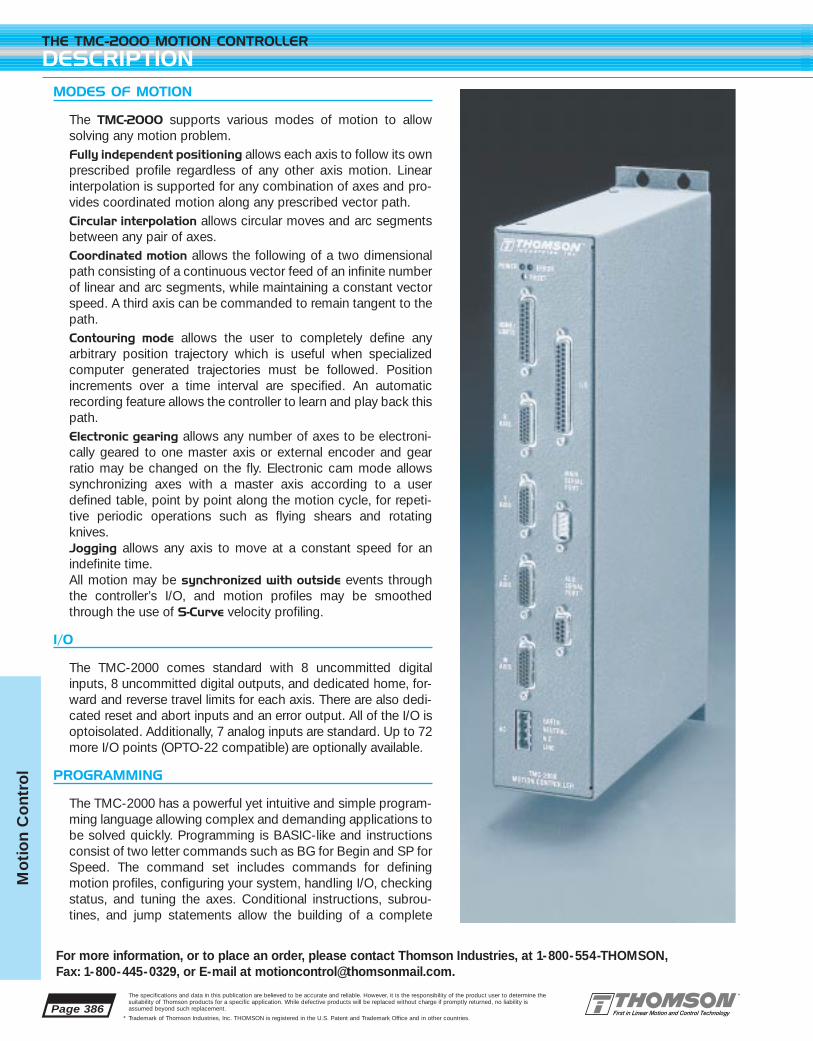
Page 386
THE TMC-2000 MOTION CONTROLLER
DESCRIPTION
For more information, or to place an order, please contact Thomson Industries, at 1-800-554-THOMSON, Fax: 1-800-445-0329, or E-mail at [email protected].
The specifications and data in this publication are believed to be accurate and reliable. However, it is the responsibility of the product user to determine thesuitability of Thomson products for a specific application. While defective products will be replaced without charge if promptly returned, no liability isassumed beyond such replacement.
* Trademark of Thomson Industries, Inc. THOMSON is registered in the U.S. Patent and Trademark Office and in other countries.
Mo
tio
n C
ont
rol
MODES OF MOTION
The TMC-2000 supports various modes of motion to allow solving any motion problem. Fully independent positioning allows each axis to follow its ownprescribed profile regardless of any other axis motion. Linear interpolation is supported for any combination of axes and pro-vides coordinated motion along any prescribed vector path. Circular interpolation allows circular moves and arc segmentsbetween any pair of axes. Coordinated motion allows the following of a two dimensionalpath consisting of a continuous vector feed of an infinite numberof linear and arc segments, while maintaining a constant vectorspeed. A third axis can be commanded to remain tangent to thepath. Contouring mode allows the user to completely define any arbitrary position trajectory which is useful when specialized computer generated trajectories must be followed. Position increments over a time interval are specified. An automaticrecording feature allows the controller to learn and play back thispath. Electronic gearing allows any number of axes to be electroni-cally geared to one master axis or external encoder and gearratio may be changed on the fly. Electronic cam mode allowssynchronizing axes with a master axis according to a userdefined table, point by point along the motion cycle, for repeti-tive periodic operations such as flying shears and rotatingknives. Jogging allows any axis to move at a constant speed for an indefinite time. All motion may be synchronized with outside events throughthe controller’s I/O, and motion profiles may be smoothedthrough the use of S-Curve velocity profiling.
I/O
The TMC-2000 comes standard with 8 uncommitted digitalinputs, 8 uncommitted digital outputs, and dedicated home, for-ward and reverse travel limits for each axis. There are also dedi-cated reset and abort inputs and an error output. All of the I/O isoptoisolated. Additionally, 7 analog inputs are standard. Up to 72more I/O points (OPTO-22 compatible) are optionally available.
PROGRAMMING
The TMC-2000 has a powerful yet intuitive and simple program-ming language allowing complex and demanding applications tobe solved quickly. Programming is BASIC-like and instructionsconsist of two letter commands such as BG for Begin and SP forSpeed. The command set includes commands for definingmotion profiles, configuring your system, handling I/O, checkingstatus, and tuning the axes. Conditional instructions, subrou-tines, and jump statements allow the building of a complete

Page 387
For more information, or to place an order, please contact Thomson Industries, at 1-800-554-THOMSON, Fax: 1-800-445-0329, or E-mail at [email protected].
THE TMC-2000 MOTION CONTROLLER
DESCRIPTION
The specifications and data in this publication are believed to be accurate and reliable. However, it is the responsibility of the product user to determine thesuitability of Thomson products for a specific application. While defective products will be replaced without charge if promptly returned, no liability isassumed beyond such replacement.
* Trademark of Thomson Industries, Inc. THOMSON is registered in the U.S. Patent and Trademark Office and in other countries.
Mo
tion C
ontro
l
machine control program. Use of the arithmetic and logic functionsand the flexibility of 254 user defined symbolic variables allow writ-ing complete self contained application programs. Multiple arraysmay contain up to 8000 elements to capture real time data forteach modes or data collection. Programs can be controlled byevent triggers, timers, and definable input interrupts And the con-troller’s multitasking capabilities allow up to 4 independent orrelated programs to run simultaneously. Programs, arrays, andvariables can be stored in nonvolatile memory and programs maybe set for automatic execution upon power up.
Programming can be performed with the controller’s own internal editor and can be quickly entered and edited with any dumbterminal or PC. However, you’ll probably prefer using the suppliedServo Setup Kit* Windows® based software. Servo Setup Kit willallow you to edit, upload and download your programs. A terminalmode allows direct communication with the controller. Tuning theaxes is simplified through an advanced assortment of autotuningand manual tuning methods. Built in scope and plotting capabilitiesallow graphical representation of position, velocity, position error,motor command, system response, and many other parameters. Allsystem configuration parameters may be viewed and set.
COMMUNICATIONS
The TMC-2000 has two RS-232 serial communication ports whichalso can be configured as RS-422. Baud rates from 300 to 38.4kbps can be used with or without handshaking. Up to 8 controllersmay be daisy chained together for control by a single host computer or by each other. Because all instructions are simple 2 letter ASCII commands, most any PLC, computer, or controller witha serial port can communicate with the TMC-2000.
SERVO PERFORMANCE
The controller supports up to 4 axes of servo and step motors. Highperformance operation is ensured through a fast servo update rate, 16 bit DAC motor command, and a fully digital PID filter withvelocity and acceleration feedforward and integration limits. S-Curve velocity profiling with different acceleration and decelera-tion rates is supported along with the ability to change position,velocity, and acceleration on the fly. Each axis may utilize an auxiliary encoder for automatic dual loop damping and backlashcompensation. And for those applications where a potentiometer or other sensor is used for feedback, the controller can close theloop around the analog inputs.
SAFETY FEATURES AND ERROR HANDLING
Prudent design of any piece of machinery dictates consideration of unexpected problems. The TMC-2000 has both software andhardware limits. The axes may be configured for automatic shut-offon excessive error. Dedicated optoisolated inputs are provided forAbort and Reset. And, sophisticated error handling may beemployed through user definable error and limit routines.
APPLICATIONS
XYZ systems
General Automation
Specialty Machinery
Pick and Place
Dispensing
Laser & Water Jet Cutting
Welding Robots
Food Processing
Coil Winding
Metalworking
Packaging Machinery
Material Handling
Web Synchronization
Tension Control
Printing and Labeling
and more!

Page 388
THE TMC-2000 MOTION CONTROLLER
SOFTWARE
For more information, or to place an order, please contact Thomson Industries, at 1-800-554-THOMSON, Fax: 1-800-445-0329, or E-mail at [email protected].
The specifications and data in this publication are believed to be accurate and reliable. However, it is the responsibility of the product user to determine thesuitability of Thomson products for a specific application. While defective products will be replaced without charge if promptly returned, no liability isassumed beyond such replacement.
* Trademark of Thomson Industries, Inc. THOMSON is registered in the U.S. Patent and Trademark Office and in other countries.
Mo
tio
n C
ont
rol
TERMINALFor programming, development, troubleshooting, oroperation, use the built in terminal for direct interaction with the controller. The program editormay be launched from here to edit, save, upload,download, and print your programs. You also maycreate a log file to capture all activity for laterreview.
STORAGE SCOPESYou can create up to four channels of storage to capture important parameters for any combinationof axes. View critical signals such as commandedposition, actual position, position error, motor command, auxiliary encoder, and I/O levels. Adjustthe trigger method, sample time, trace colors, gridtypes, values, min/max levels, and more.
TUNINGChoose from one of five tuning routines that bestsuits your application. You can completely handsoff auto-tune or, if you prefer, interact by specifying acrossover frequency, gain, or damping. Either way,the resulting system response is displayed.

Page 389
For more information, or to place an order, please contact Thomson Industries, at 1-800-554-THOMSON, Fax: 1-800-445-0329, or E-mail at [email protected].
THE TMC-2000 MOTION CONTROLLER
SOFTWARE
The specifications and data in this publication are believed to be accurate and reliable. However, it is the responsibility of the product user to determine thesuitability of Thomson products for a specific application. While defective products will be replaced without charge if promptly returned, no liability isassumed beyond such replacement.
* Trademark of Thomson Industries, Inc. THOMSON is registered in the U.S. Patent and Trademark Office and in other countries.
Mo
tion C
ontro
l
SYSTEM EVALUATIONEvaluate the servo performance though an absolute stability test, step response test, or frequencyresponse on either the open-loop or closed loopresponse. Check for problems with gain or dampingand get a graphical look at the responsiveness ofyour system.
SYSTEM INFORMATIONA detailed listing of all system parameters can beviewed for diagnostic or troubleshooting purposes.Check the status of error codes, motion relatedvariables, all I/O, limit switches and more.
SYSTEM OVERVIEWA quick overview of the state of important system variables such as encoder positions, digital andanalog I/O status, limit and home switch states.

Page 390
THE TMC-2000 MOTION CONTROLLER
COMMAND SUMMARY
For more information, or to place an order, please contact Thomson Industries, at 1-800-554-THOMSON, Fax: 1-800-445-0329, or E-mail at [email protected].
The specifications and data in this publication are believed to be accurate and reliable. However, it is the responsibility of the product user to determine thesuitability of Thomson products for a specific application. While defective products will be replaced without charge if promptly returned, no liability isassumed beyond such replacement.
* Trademark of Thomson Industries, Inc. THOMSON is registered in the U.S. Patent and Trademark Office and in other countries.
Mo
tio
n C
ont
rol
MOTION
AB Abort MotionAC AccelerationBG Begin MotionCD Contour DataCM Contour ModeCR CircleCS Clear Motion
SequenceDC DecelerationDT Contour Time
IntervalES Ellipse ScalingFE Find EdgeFI Find IndexGA Master Axis for
GearingGR Gear RatioHM HomeIP Increment PositionJG Jog ModeLE Linear Interpolation
EndLI Linear Interpolation
DistanceLM Linear Interpolation
modePA Position AbsolutePR Position RelativeSP SpeedST StopTN TangentVA Vector AccelerationVD Vector DecelerationVE Vector Sequence
EndVM Coordinated Motion
ModeVR Vector Speed RatioVP Vector PositionVS Vector Speed
PROGRAM FLOW
AD After DistanceAI After InputMF After Motion–
Forward DirectionAM After Motion–
CompleteAP After Absolute
PositionAR After Relative
Distance
AS At SpeedAT After TimeAV After Vector
DistanceEA Choose ECAM
MasterEB Enable CAMEG Engage ECAMEM CAM Cycle
CommandEN End ProgramEP CAM Interval and
Starting PointEQ Disengage ECAMET ECAM Table EntryHX Halt ExecutionJP Jump to LocationJS Jump to SubroutineMC After In PositionMF After Motion —
Forward DirectionMG MessageMR After Motion —
Reverse DirectionNO No OperationRE Return from Error
SubroutineRI Return from
InterruptTW Timeout for In
PositionWC Wait for Contour
DataWT WaitXQ Execute ProgramZS Zero Subroutine
Stack
GENERAL CONFIGURATION
AF Analog FeedbackAL Arm LatchBN BurnBP Burn ProgramBV Burn VariablesCB Clear BitCC Configure Com PortCE Configure Encoder
TypeCI Communication
InterruptCN Configure Switches
and StepperCO Configure Outputs
DA Deallocate ArraysDE Define Dual
Encoder PositionDL DownloadDM Dimension ArraysDP Define PositionED Edit ModeEI Enable InterruptsEO Echo OffLS ListMO Motor OffMT Motor Type DefineOB Output BitOP Output PortPF Position FormatQU Upload ArrayQD Download ArrayRA Record ArrayRC RecordRD Record DataRI Interrupt MaskRS ResetSB Set BitUI User InterruptUL UploadVF Variable Format
CONTROL FILTER SETTINGS
DV Damping for Dual Loop
FA Acceleration Feedforward
FV Velocity FeedforwardGN GainIL Integrator LimitIT Smoothing Time
Constant – Independent
KD Derivative Constant
KI Integrator ConstantKP Proportional
ConstantKS Stepper Smoothing
ConstantOF OffsetSH Servo HereTL Torque LimitTM Sample TimeVT Smoothing Time
Constant – VectorZR Zero
STATUS
RP Report Command Position
RL Report LatchSC Stop CodeTB Tell StatusTC Tell Error CodeTD Tell Dual EncoderTE Tell ErrorTI Tell InputTP Tell PositionTR TraceTS Tell SwitchesTT Tell TorqueTV Tell Velocity
ERROR AND LIMITS
BL Reverse Software Limit
ER Error LimitFL Forward Software
LimitOE Off on Error
EDITOR
ED Edit Mode<return> Save Line<cntrl> P Previous Line<cntrl> I Insert Line<cntrl> D Delete Line<cntrl> Q Quit Editor
ARITHMETIC FUNCTIONS
@SIN Sine@COM Complement@COS Cosine@ABS Absolute Value@FRAC Fraction Portion@INT Integer Portion@RND Round@SQR Square Root@IN Return Digital Input@AN Return Analog Input+ Add- Subtract* Multiply/ Divide& And| Or( ) Parentheses
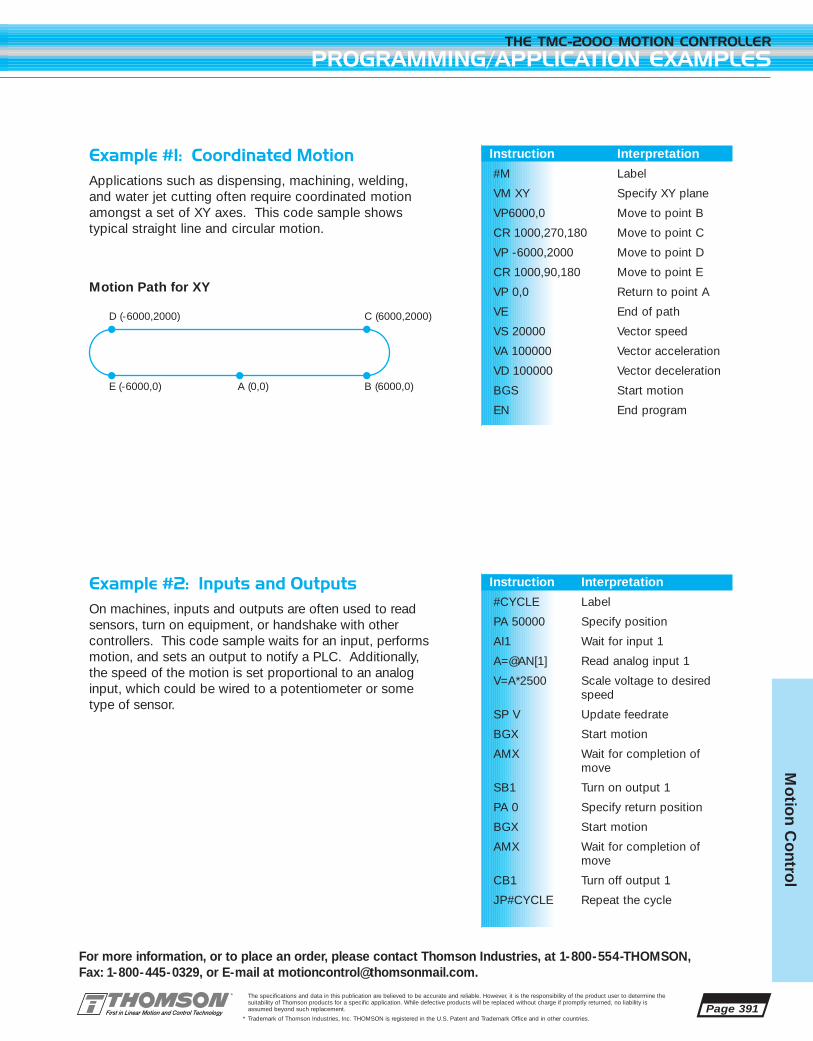
Page 391
For more information, or to place an order, please contact Thomson Industries, at 1-800-554-THOMSON, Fax: 1-800-445-0329, or E-mail at [email protected].
THE TMC-2000 MOTION CONTROLLER
PROGRAMMING/APPLICATION EXAMPLES
The specifications and data in this publication are believed to be accurate and reliable. However, it is the responsibility of the product user to determine thesuitability of Thomson products for a specific application. While defective products will be replaced without charge if promptly returned, no liability isassumed beyond such replacement.
* Trademark of Thomson Industries, Inc. THOMSON is registered in the U.S. Patent and Trademark Office and in other countries.
Mo
tion C
ontro
l
Example #1: Coordinated MotionApplications such as dispensing, machining, welding, and water jet cutting often require coordinated motionamongst a set of XY axes. This code sample shows typical straight line and circular motion.
Motion Path for XY
Example #2: Inputs and OutputsOn machines, inputs and outputs are often used to readsensors, turn on equipment, or handshake with other controllers. This code sample waits for an input, performsmotion, and sets an output to notify a PLC. Additionally,the speed of the motion is set proportional to an analoginput, which could be wired to a potentiometer or sometype of sensor.
Instruction Interpretation
#M Label
VM XY Specify XY plane
VP6000,0 Move to point B
CR 1000,270,180 Move to point C
VP -6000,2000 Move to point D
CR 1000,90,180 Move to point E
VP 0,0 Return to point A
VE End of path
VS 20000 Vector speed
VA 100000 Vector acceleration
VD 100000 Vector deceleration
BGS Start motion
EN End program
Instruction Interpretation
#CYCLE Label
PA 50000 Specify position
AI1 Wait for input 1
A=@AN[1] Read analog input 1
V=A*2500 Scale voltage to desiredspeed
SP V Update feedrate
BGX Start motion
AMX Wait for completion ofmove
SB1 Turn on output 1
PA 0 Specify return position
BGX Start motion
AMX Wait for completion ofmove
CB1 Turn off output 1
JP#CYCLE Repeat the cycle
D (-6000,2000)
E (-6000,0) A (0,0)
C (6000,2000)
B (6000,0)

Page 392
THE TMC-2000 MOTION CONTROLLER
PROGRAMMING/APPLICATION EXAMPLES
For more information, or to place an order, please contact Thomson Industries, at 1-800-554-THOMSON, Fax: 1-800-445-0329, or E-mail at [email protected].
The specifications and data in this publication are believed to be accurate and reliable. However, it is the responsibility of the product user to determine thesuitability of Thomson products for a specific application. While defective products will be replaced without charge if promptly returned, no liability isassumed beyond such replacement.
* Trademark of Thomson Industries, Inc. THOMSON is registered in the U.S. Patent and Trademark Office and in other countries.
Mo
tio
n C
ont
rol
Example #3: Loops and VariablesMachines often need to repeat a cycle a certain numberof times. This code sample shows how a variable, V1,can be used to create a counter. The motion cyclesback and forth, each time incrementing the counter.When 10 cycles are complete, the program ends.
Example #4: Electronic GearingSome applications require axes to follow another masterencoder in a synchronized or geared configuration. Inthis example, three rotating dies repetitively stamp material traversing on a conveyor. It is important thatthe dies rotate at the same surface speed as the materi-al. When the operator presses the start switch, the axesrotate and cycle the dies by following the conveyormotor. The gear ratio is set by an operator depending onthe size of the die.
Instruction Interpretation
#MAIN Label
V1=1 Set counter variable to 1
#LOOP Label for loop
PA 25000 Set move distance
BG X Begin move
AM X Wait for move completion
PA 0 Set move distance
BG X Begin move
AM X Wait for move completion
V1=V1+1 Increment cycle counter
JP #LOOP, V1<10 Loop until counter = 10
EN Program end
Instruction Interpretation
#MAIN Label
IN“Enter die size”, A Prompt operator fordie size
A=A*3.33 Scale gear ratio asrequired
GAW Designate W as master (conveyor) axis
JG,4000 Start conveyor running
#CYCLE Label
AI1 Wait for start switch
GR A,A,A Start stamping by setting ratios for X, Y,and Z
AI2 Wait for stop switch
GR 0,0,0 Stop stamping by disabling gearing
JP #CYCLE

Page 393
For more information, or to place an order, please contact Thomson Industries, at 1-800-554-THOMSON, Fax: 1-800-445-0329, or E-mail at [email protected].
THE TMC-2000 MOTION CONTROLLER
SPECIFICATIONS
The specifications and data in this publication are believed to be accurate and reliable. However, it is the responsibility of the product user to determine thesuitability of Thomson products for a specific application. While defective products will be replaced without charge if promptly returned, no liability isassumed beyond such replacement.
* Trademark of Thomson Industries, Inc. THOMSON is registered in the U.S. Patent and Trademark Office and in other countries.
Mo
tion C
ontro
l
SERVO Number of axes 4 axes, any combination of servo and stepperFeedback Incremental encoder, single ended or differential. Can also use analog voltage
from potentiometer or transducerServo Loop Update Time 500 µsPosition Accuracy +/-1 quadrature countPosition Range +/-2147483647 counts per move; automatic rollover and no limit in jog
or vector modesVelocity Accuracy: Long Term Phase-locked, better than .003%
Short Term System dependentVelocity Range Up to 8,000,000 counts/secVelocity Resolution 2 counts/secAccel/Decel Range 1024 to 67,107,840 counts/s2
Motor Command Resolution 16-bit or 0.0003VBlock Execution Time In contour mode, up to 1000 (moves)/sec with full trajectory generationSynchronization All axes in the same unit are perfectly synchronized and share the same servo
cycle. Multiple controllers may share the same synchronization signal and be perfectly synchronized in the same servo cycle
Position Capture Accuracy 25µs with optoisolation, 0.1µs bypassed optoisolationGear Ratio +/- 127.9999Step Pulse Frequency 2,000,000 pulses/sec maximum
PROGRAMMINGNumber of Variables 254Variable Range +/-2 billionVariable Resolution 1•10-4
Array Size 8000 elements in up to 30 arraysProgram Size 1000 lines x 80 characters
INPUTS / OUTPUTSGeneral Purpose Inputs 8 uncommitted optoisolated, open collector 28V@ 25mA maxGeneral Purpose Outputs 8 uncommitted optoisolated, open collector 28V@ 25mA maxGeneral Purpose Analog Inputs 7 +/- 10V, 12 bit resolutionLimit Inputs Dedicated forward and reverse limit inputs for each axis, optoisolatedHome Inputs Dedicated home input for each axis, optoisolatedOther Reset input, Abort input, and Error output
ELECTRICAL Servo ACMD Amplifier Command +/-10 Volts analog signal. Resolution 16-bit, .0003 Volts. 3 mA maximumEncoder A+,A-,B+,B-,IDX+,IDX- TTL compatible, but can accept up to +/-12 Volts. Quadrature phase
on CHA,CHB. Can accept single-ended (A+,B+ only) or differential (A+,A-,B+,B-). Maximum A, B edge rate: 8 MHz. Minimum IDX pulse width: 120 nsec.
Stepper Pulse TTL (0-5 Volts) level at 50% duty cycle. 2,000,000 pulses/sec maximum frequency
Stepper Direction TTL (0-5 Volts)Uncommitted Inputs, Limits, Home, Reset and Abort Inputs 2.2K ohm in series with optoisolator. Requires at least 1 mA for on. Can accept
up to 28 Volts without additional series resistor. Above 28 Volts requires additional resistor.
AN[1] thru AN[7] Analog Inputs Standard configuration is +/-10 Volt. 12-Bit Analog-to-Digital converter.OUT[1] thru OUT[8] Outputs Optoisolated, open collectorAvailable Power For External Devices + 5V 1.5 A
+12V 750 mA-12V 200 mA
COMMUNICATIONSNumber of Communication Ports 2 serial RS-232 (can be configured for RS-422)Speed 300, 1200, 4800, 9600, 19200, 38400 bpsHandshaking Hardware or none

Page 394
THE TMC-2000 MOTION CONTROLLER
CONNECTION PINOUTS
For more information, or to place an order, please contact Thomson Industries, at 1-800-554-THOMSON, Fax: 1-800-445-0329, or E-mail at [email protected].
The specifications and data in this publication are believed to be accurate and reliable. However, it is the responsibility of the product user to determine thesuitability of Thomson products for a specific application. While defective products will be replaced without charge if promptly returned, no liability isassumed beyond such replacement.
* Trademark of Thomson Industries, Inc. THOMSON is registered in the U.S. Patent and Trademark Office and in other countries.
Mo
tio
n C
ont
rol
RS-232 Main Serial Port
Connector Type: 9 pin male D subPin Function
1 CTS – output2 Transmit Data – output3 Receive Data – input4 RTS – input5 Ground6 CTS – output7 RTS – input8 CTS – output9 No connect/ or
5V or sample clock with jumpers
RS-232 Ð Auxiliary SerialPort Connector
Connector Type: 9 pin female D subPin Function
1 CTS – input2 Transmit Data – input3 Receive Data – output4 RTS – output5 Ground6 CTS – input7 RTS – output8 CTS – input9 5V / or no connect or
sample clock with jumpers
*RS-232 ports can be configured forRS-422 by factory
Pin Function
15,16,17 Controller supplied 5V18,19,20,21 Controller supplied 22,23,24,25 ground1,14 User isolated inputs
Vcc, LSCOM2 X + limit3 X - limit4 X home
Pin Function
5 Y + limit6 Y - limit7 Y home8 Z + limit9 Z - limit10 Z home11 W + limit12 W - limit13 W home
AC Power Connector
Connector Type: 4 position Phoenix screw terminalPin Function
LINE Hot wire of AC power cord – blackN.C. Do not connect (used for key)NEUTRAL Return of AC power cord – whiteEARTH Chassis ground – green
I/O Connector
Connector Type: 37 pin female D sub
Pin Function
28,17 Controllersupplied 5V
10,11, Controller 29,30, supplied 36 Ground16,35 User isolated
inputs Vcc INCOM
1,20 User isolated outputs ground
Pin Function
34 input 1 (latch X)15 input 2 (latch Y)33 input 3 (latch Z)14 input 4 (latch W)32 input 5 13 input 6 31 input 7 12 input 8
Pin Function
2 output 121 output 23 output 3 22 output 44 output 523 output 65 output 724 output 86 analog 1
Pin Function
25 analog 27 analog 3 26 analog 48 analog 527 analog 69 analog 719 abort input37 error output18 reset input
X, Y, Z, W Axis Connectors
Connector Type: 26 pin high densityfemale D sub, one per axisPin # Function
1 enc A+2 enc A-3 enc B+4 enc B-5 enc I+6 enc I-7 enc gnd8 enc 5V9 enc shield10 amp cmd11 amp enable 12 amp PWM/step13 amp sign/dir14 amp enable Vx15 stepper mode enable17 amp gnd18 amp shield16, 23 gnd24 +5V26 +12V25 -12V19,20,21,22 N.C.
HOME/LIMITS Connector
Connector Type: 25 pin female D sub
Auxiliary Encoder Connector J3
Connector Type: 20 pin male ribbon header. It is internallymounted and noted as J3. Remove side cover for access.Pin Function
1 Sampleclock
2 Synch3 B-Aux W4 B+Aux W5 A-Aux W6 A+Aux W7 B-Aux Z
Pin Function
8 B+Aux Z 9 A-Aux Z 10 A+Aux Z11 B-Aux Y12 B+Aux Y13 A-Aux Y14 A+Aux Y
Pin Function
15 B-Aux X16 B+Aux X17 A-Aux X18 A+Aux X19 5 Volt20 Ground

MAINSERIALPORT
AUXSERIALPORT
EARTHNEUTRALN.C. LINE
2.58
Ø.357
1.288
.733
1.11
.190
Ø.187
13.48 14.00
8.00
Page 395
For more information, or to place an order, please contact Thomson Industries, at 1-800-554-THOMSON, Fax: 1-800-445-0329, or E-mail at [email protected].
THE TMC-2000 MOTION CONTROLLER
DIMENSIONS
The specifications and data in this publication are believed to be accurate and reliable. However, it is the responsibility of the product user to determine thesuitability of Thomson products for a specific application. While defective products will be replaced without charge if promptly returned, no liability isassumed beyond such replacement.
* Trademark of Thomson Industries, Inc. THOMSON is registered in the U.S. Patent and Trademark Office and in other countries.
Mo
tion C
ontro
l
NOTE:DIMENSIONS ARE IN INCHES
MOTION CONTROLLER

Page 396
THE TMC-2000 MOTION CONTROLLER
ORDERING INFORMATION
For more information, or to place an order, please contact Thomson Industries, at 1-800-554-THOMSON, Fax: 1-800-445-0329, or E-mail at [email protected].
The specifications and data in this publication are believed to be accurate and reliable. However, it is the responsibility of the product user to determine thesuitability of Thomson products for a specific application. While defective products will be replaced without charge if promptly returned, no liability isassumed beyond such replacement.
* Trademark of Thomson Industries, Inc. THOMSON is registered in the U.S. Patent and Trademark Office and in other countries.
Mo
tio
n C
ont
rol
Ordering InformationTMC 2004-CO 4 axis Motion Controller
Accessories19260A TMC-2000 manual. Note: one manual is included with each controller.
21365B Cable for direct connection of the TMC-2000 motion controller to any OMNIDRIVE* digitalservo drive or AXI-PAK* servo axis package. 36” length
21210B Cable, same as above 21365B, with the addition of a separate pigtail to access all signalsof the OMNIDRIVE that are unused by the TMC-2000 motion controller.

A THOMSON AXI-PAKservo axis package is the simplest way to a highperformance and cost effective servo solution.An AXI-PAK is a tested and proven combination of a BLX brushless servo motor, an OMNIDRIVE*digital servo drive, and the required cables allunder a single part number. Pre-engineered andpre-matched components ensure optimized performance and take the guesswork and worryout of compatibility and installation issues. Weput it together so you can put it to work.
An AXI-PAK can operate as a smart standalone drive, or if the application requires it, caneasily connect to a motion controller (such as incoordinated multi-axis systems). As a smart digital drive, it can be configured to operate in
torque, velocity, or position modes. It can accept
the standard +/- 10V analog command signal
from a motion control card, digital commands
from a host computer via its serial link, or step
and direction inputs and function as a high
performance alternative to a stepper drive.
Its programmable I/O and preset speeds
allow it to be used as a variable speed drive.
It can even follow a master encoder with
electronic gearing.
AXI-PAK servo axis packages are also available
in an indexing version capable of executing up to
eight different position moves initiated by the digi-
tal I/O as well as a user defined homing routine.
This indexing option eliminates the need for a
separate motion control card in many applications.
FEATURES
■ A turnkey motor and drive package
■ Operates with a motion controlleror as a smart stand alone drive
■ Four motor frame sizes to fit yourrequirements
■ Continuous torque ratings from 4.2to 280 in-lb, peak torque ratingsfrom 11.0 in-lb to 840 in-lb
■ Includes all cabling
■ Digital drives operate in torque,velocity, or position modes
■ High torque maintenance freebrushless servo motors featureIP65 sealing, MS style fluid tightconnectors, oversize bearings, and a winding thermal switch and internal 2000 (8000 count) linecommutating encoder
■ Simple one cable connection toTMC-2000 controller for complexor multi axis applications
■ All components carry UL, cUL,and CE approvals
■ Off-the-shelf delivery
Page 397
AXI-PAK* SERVO AXIS PACKAGE
For Application Engineering assistance contact the Thomson Technical HelpLine at 1-800-554-8466.* Trademark of Thomson Industries, Inc. THOMSON is registered in the U.S. Patent and Trademark Office and in other countries.
Mo
tion C
ontro
l

Page 398
AXI-PAK* SERVO AXIS PACKAGE
MODES OF OPERATION
For more information, or to place an order, please contact Thomson Industries, at 1-800-554-THOMSON, Fax: 1-800-445-0329, or E-mail at [email protected].
The specifications and data in this publication are believed to be accurate and reliable. However, it is the responsibility of the product user to determine thesuitability of Thomson products for a specific application. While defective products will be replaced without charge if promptly returned, no liability isassumed beyond such replacement.
* Trademark of Thomson Industries, Inc. THOMSON is registered in the U.S. Patent and Trademark Office and in other countries.
Mo
tio
n C
ont
rol
CONTROL BY SERVO OR STEPPER CONTROLLER
Use an AXI-PAK servo axis package without indexing for direct control by any servo or stepper controller. Either a+/- 10V torque/velocity command or step and direction signals may be used as a command source. Ideal for usewith the TMC-2000 multi-axis controller.
STAND ALONE BASIC POSITIONING
For basic point to point positioning applications, the AXI-PAK with servo axis package indexing option allows thedrive to execute up to eight different position moves initiated by the drive’s digital I/O. In many cases, a separatemotion control card is not needed. Connect to your I/O card, PLC, or switch panel for a simple solution
SLAVE TO A MASTER ENCODER
Any AXI-PAK servo axis package can use an incremental encoder source as a command signal. This feature canbe used to have an AXI-PAK follow a master encoder or even another AXI-PAK. Multiple axes can be a slave toa master without requiring a multi-axis controller or a gantry configuration can be easily implemented. The gearratio of this electronic gearing feature is easily set in OMNILINK* setup software.
CONTROL BY HOST THROUGH SERIAL INTERFACE
An AXI-PAK servo axis package can be controlled through its host command language via its serial interface port.In this way, a PC, PLC, or any host computer may constantly change all parameters including acceleration, veloc-ity, move distance, and I/O configuration. This gives the AXI-PAK maximum flexibility.
+/-10 V analog or step/dir
12-24 VDCDigital I/O
RS-232/RS-485
In general, an AXI-PAK without indexing is used when a separate servo or stepper controller (such as the TMC-2000) is utilized. The indexing option is required to give the AXI-PAK basic stand alone positioning capabilities.

Page 399
For more information, or to place an order, please contact Thomson Industries, at 1-800-554-THOMSON, Fax: 1-800-445-0329, or E-mail at [email protected].
AXI-PAK* SERVO AXIS PACKAGE
DESCRIPTION
The specifications and data in this publication are believed to be accurate and reliable. However, it is the responsibility of the product user to determine thesuitability of Thomson products for a specific application. While defective products will be replaced without charge if promptly returned, no liability isassumed beyond such replacement.
* Trademark of Thomson Industries, Inc. THOMSON is registered in the U.S. Patent and Trademark Office and in other countries.
Mo
tion C
ontro
l
OMNIDRIVE Ð Power and Flexibility
The heart of every AXI-PAK servo axis package is anOMNIDRIVE* digital servo drive. Available in both fullsize and mini versions, this fully digital drive is suitablefor a myriad of motion control applications. With theoptional indexing functionality, it makes an ideal stand
alone positioner for basic point to point motion. Withoutthe indexing option, it is a high performance drive usinga command source from a servo or stepper motion controller (such as the TMC-2000), PLC, masterencoder, or host computer.
Communications are providedthrough an RS-232/RS-485 serialport (2 ports on full size drive).OMNI LINK* software running onyour PC is used for quick point andclick configuration.
Various Modes of Operation arepossible including analog torque,velocity, and position, digital presetvelocity or torque, master encoderfollower with electronic gearing,step/dir input, and serial commandsfrom a host computer. The indexingoption adds eight preset positionsas well as homing.
Precise Motor Control of brushlessmotors is provided through fully digital position, velocity, and currentloops. Sine wave commutation viaencoder feedback, special controlalgorithms, and latest generationIGBT power modules ensure peakperformance and reliability.
Fully Digital Design provides theultimate in performance, features,and functionality as well as provid-ing a system that is stable overtime and temperature
The Indexing Option extends thedrives functionality by allowing upto eight different move profiles initiated by the digital I/O as well asa user defined homing routine.
Flexible I/O is user definable.Inputs can be set as: various enableand preset selects, start index, start home, fault reset, drive modeselect, mode override, and more.Outputs can be set as: in position orspeed window, in motion, sequence complete, various fault indicators,home status, and more. Analog outputs can reproduce importantvoltage, current, error, and feedbacksignals.
Power Ratings are 0.5, 1, and 2 kWfor the mini version and 1, 2, 3, 7.5,and 15 kW for the full size version.Full size drives add a 24V user I/Osupply and internal regenerationresistor.
MINI SIZE FULL SIZE

Although an AXI-PAK package comes pre-configuredfor its motor, there may be times where an applica-tion requires special settings. The Drive Parametersscreen may be used to set current limits, error limits,scaling, offsets, and more.
With just a click, the drive can be configured for awide variety of operational modes (torque, velocity,position, step/dir, follower, etc.) Communicationsparameters may be set for single or multi-drop operation.
Page 400
AXI-PAK* SERVO AXIS PACKAGE
DESCRIPTION
For more information, or to place an order, please contact Thomson Industries, at 1-800-554-THOMSON, Fax: 1-800-445-0329, or E-mail at [email protected].
The specifications and data in this publication are believed to be accurate and reliable. However, it is the responsibility of the product user to determine thesuitability of Thomson products for a specific application. While defective products will be replaced without charge if promptly returned, no liability isassumed beyond such replacement.
* Trademark of Thomson Industries, Inc. THOMSON is registered in the U.S. Patent and Trademark Office and in other countries.
Mo
tio
n C
ont
rol
Digital inputs can be configured for homing, reset,enable, indexing, and more. Digital outputs may bedefined for various signals as well. Analog outputsmay be set for a variety of position, velocity, current,voltage and error signals.
All important drive signals may be plotted realtimeusing the oscilloscope utility. Additional windowsallow a numerical display of all signals as well aserror codes, status codes, fault history, tuning para-meters, and more.
OMNI LINK* Setup Software
Every AXI-PAK servo axis package comes with OMNILINK software, a Windows® based interface tool forsetup, configuration, and diagnostics. OMNI LINK soft-ware provides a complete graphical interface to the drivewith absolutely no programming language to learn. A
drive is configured by simply clicking on the appropriateoption box or entering values in existing fields. A varietyof intuitive screens guide you through configuration, signal monitoring, and diagnostics.

Page 401
For more information, or to place an order, please contact Thomson Industries, at 1-800-554-THOMSON, Fax: 1-800-445-0329, or E-mail at [email protected].
AXI-PAK* SERVO AXIS PACKAGE
INDEXING OPTION
The specifications and data in this publication are believed to be accurate and reliable. However, it is the responsibility of the product user to determine thesuitability of Thomson products for a specific application. While defective products will be replaced without charge if promptly returned, no liability isassumed beyond such replacement.
* Trademark of Thomson Industries, Inc. THOMSON is registered in the U.S. Patent and Trademark Office and in other countries.
Mo
tion C
ontro
l
Indexing Option
When not using an AXI-PAK servo axis package in conjunction with a separate motion controller, you’ll likely be interested in the indexing option. This indexingcapability allows an AXI-PAK to act as a simple controllerfor basic point-to-point positioning applications. Using the OMNI LINK* setup software, the drive may beconfigured for up to eight different position moves (index-es) initiated by the drive’s digital I/O. As the OMNI LINKsoftware only requires you to enter parameters in existingfields, there is no programming language to learn. Themoves may be incremental (a distance relative to the current position), absolute (a distance relative to home
position), or registration (a distance relative to the registration sensor input). Velocity, acceleration, andmove distance may be specified for each index, as wellas a batch count that will automatically repeat any indexa specified number of times. A dwell time between movesalso may be set. Through an “action when complete”setting, each index may be linked to any other for auto-matic subsequent execution. And for those cases wherea host computer is employed, an infinite number of moves may be executed by sending parameter infor-mation to the drive via the serial interface. The indexingoption also includes a user defined homing routine.
No Programming Language to Learn!
Up to eight indexes are defined using OMNI LINK setupsoftware with a simple point and click. Absolute, relative,and registration moves are supported. Moves are initiated by the drive’s digital I/O.
User Defined Homing Routine
You can home to a sensor switch and/or encoder marker,as well as set homing speed and acceleration, and enteran offset distance. Homing may begin automatically upondrive enable or through an assignable input.

Page 402
AXI-PAK* SERVO AXIS PACKAGE
DESCRIPTION
For more information, or to place an order, please contact Thomson Industries, at 1-800-554-THOMSON, Fax: 1-800-445-0329, or E-mail at [email protected].
The specifications and data in this publication are believed to be accurate and reliable. However, it is the responsibility of the product user to determine thesuitability of Thomson products for a specific application. While defective products will be replaced without charge if promptly returned, no liability isassumed beyond such replacement.
* Trademark of Thomson Industries, Inc. THOMSON is registered in the U.S. Patent and Trademark Office and in other countries.
Mo
tio
n C
ont
rol
A Motor Built To Last
Each AXI-PAK servo axis package includes a Thomson BLX Seriesbrushless servo motor. There are four frame sizes of motors avail-able, each with a variety of winding configurations that are an engineered match to the OMNIDRIVE* servo drive. This high performance, industrial quality motor is built to last. Brushless construction, oversize lifetime lubricated bearings, MS style fluidtight connectors, IP65 sealing, and a winding thermal switchensure a long and trouble free life in the harshest and most challenging applications. An internally mounted 2000 line encoder(8000 counts) with integral commutation sensors and its own bearing system provides the precision and resolution for your highperformance application.
• Maintenance free brushless construction
• High energy rare earth magnets
• Standard IP65 for washdown environments
• MS style connectors for durability
• Internal winding thermal switch
• UL and cUL recognized
The Right Cables
“The devil is in the details” – a saying quite appropriate for sucha seemingly simple item as cabling. Experienced engineers andtechnicians know very well that properly built cables make the difference in getting a machine up and running quickly – and keeping it running. That is why Thomson has tooled up to provide you with professionally molded, high quality cable assem-blies that just drop in, saving you time and worry. Our cablesincorporate features such as 360° shielding of both cable andconnectors for EMC compliance, UL approved oil and chemicalresistant cable, and fully molded connector housings with integralstrain reliefs. Each AXI-PAK includes all cables for a quick, complete and trouble-free installation.
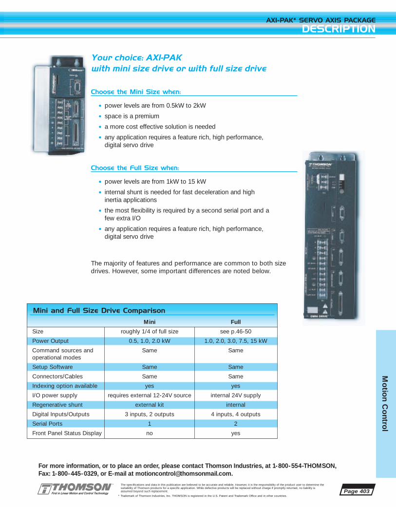
Page 403
For more information, or to place an order, please contact Thomson Industries, at 1-800-554-THOMSON, Fax: 1-800-445-0329, or E-mail at [email protected].
AXI-PAK* SERVO AXIS PACKAGE
DESCRIPTION
The specifications and data in this publication are believed to be accurate and reliable. However, it is the responsibility of the product user to determine thesuitability of Thomson products for a specific application. While defective products will be replaced without charge if promptly returned, no liability isassumed beyond such replacement.
* Trademark of Thomson Industries, Inc. THOMSON is registered in the U.S. Patent and Trademark Office and in other countries.
Mo
tion C
ontro
l
Your choice: AXI-PAKwith mini size drive or with full size drive
Choose the Mini Size when:
• power levels are from 0.5kW to 2kW
• space is a premium
• a more cost effective solution is needed
• any application requires a feature rich, high performance, digital servo drive
Choose the Full Size when:
• power levels are from 1kW to 15 kW
• internal shunt is needed for fast deceleration and high inertia applications
• the most flexibility is required by a second serial port and a few extra I/O
• any application requires a feature rich, high performance, digital servo drive
The majority of features and performance are common to both size drives. However, some important differences are noted below.
Mini and Full Size Drive Comparison
Mini Full
Size roughly 1/4 of full size see p.46-50
Power Output 0.5, 1.0, 2.0 kW 1.0, 2.0, 3.0, 7.5, 15 kW
Command sources and Same Sameoperational modes
Setup Software Same Same
Connectors/Cables Same Same
Indexing option available yes yes
I/O power supply requires external 12-24V source internal 24V supply
Regenerative shunt external kit internal
Digital Inputs/Outputs 3 inputs, 2 outputs 4 inputs, 4 outputs
Serial Ports 1 2
Front Panel Status Display no yes
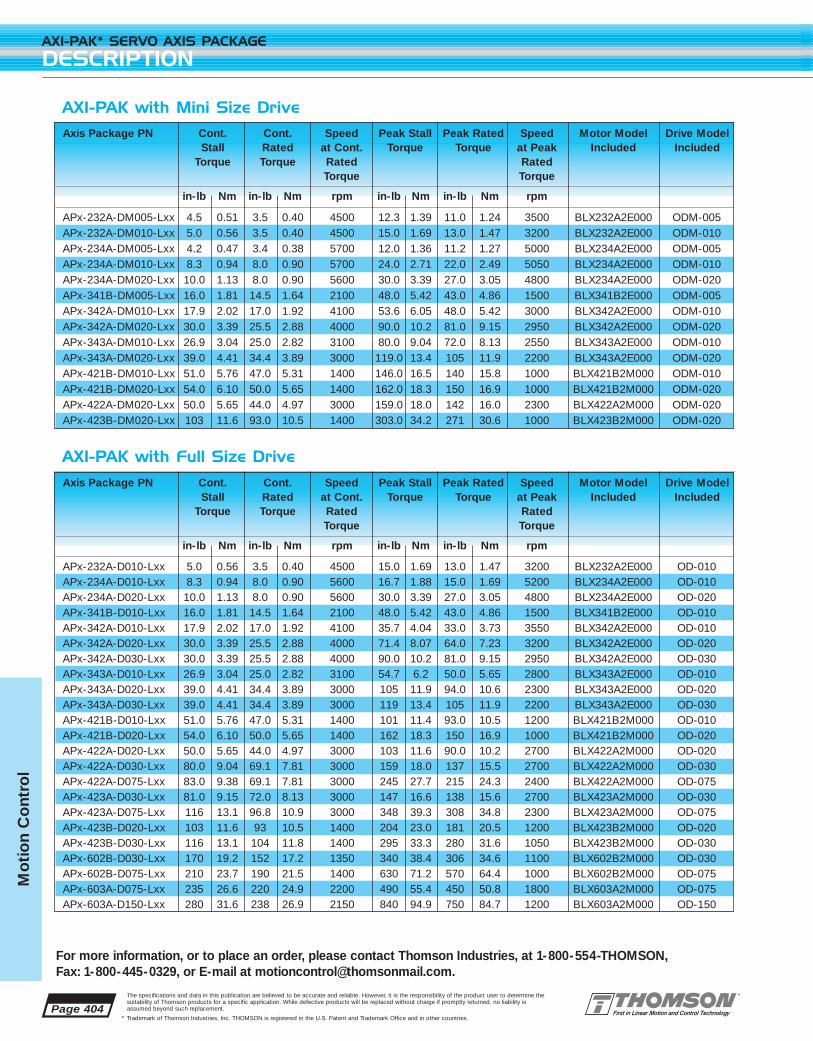
Page 404
AXI-PAK* SERVO AXIS PACKAGE
DESCRIPTION
For more information, or to place an order, please contact Thomson Industries, at 1-800-554-THOMSON, Fax: 1-800-445-0329, or E-mail at [email protected].
The specifications and data in this publication are believed to be accurate and reliable. However, it is the responsibility of the product user to determine thesuitability of Thomson products for a specific application. While defective products will be replaced without charge if promptly returned, no liability isassumed beyond such replacement.
* Trademark of Thomson Industries, Inc. THOMSON is registered in the U.S. Patent and Trademark Office and in other countries.
Mo
tio
n C
ont
rol
Axis Package PN Cont. Cont. Speed Peak Stall Peak Rated Speed Motor Model Drive ModelStall Rated at Cont. Torque Torque at Peak Included Included
Torque Torque Rated RatedTorque Torque
in-lb Nm in-lb Nm rpm in-lb Nm in-lb Nm rpm
APx-232A-DM005-Lxx 4.5 0.51 3.5 0.40 4500 12.3 1.39 11.0 1.24 3500 BLX232A2E000 ODM-005APx-232A-DM010-Lxx 5.0 0.56 3.5 0.40 4500 15.0 1.69 13.0 1.47 3200 BLX232A2E000 ODM-010APx-234A-DM005-Lxx 4.2 0.47 3.4 0.38 5700 12.0 1.36 11.2 1.27 5000 BLX234A2E000 ODM-005APx-234A-DM010-Lxx 8.3 0.94 8.0 0.90 5700 24.0 2.71 22.0 2.49 5050 BLX234A2E000 ODM-010APx-234A-DM020-Lxx 10.0 1.13 8.0 0.90 5600 30.0 3.39 27.0 3.05 4800 BLX234A2E000 ODM-020APx-341B-DM005-Lxx 16.0 1.81 14.5 1.64 2100 48.0 5.42 43.0 4.86 1500 BLX341B2E000 ODM-005APx-342A-DM010-Lxx 17.9 2.02 17.0 1.92 4100 53.6 6.05 48.0 5.42 3000 BLX342A2E000 ODM-010APx-342A-DM020-Lxx 30.0 3.39 25.5 2.88 4000 90.0 10.2 81.0 9.15 2950 BLX342A2E000 ODM-020APx-343A-DM010-Lxx 26.9 3.04 25.0 2.82 3100 80.0 9.04 72.0 8.13 2550 BLX343A2E000 ODM-010APx-343A-DM020-Lxx 39.0 4.41 34.4 3.89 3000 119.0 13.4 105 11.9 2200 BLX343A2E000 ODM-020APx-421B-DM010-Lxx 51.0 5.76 47.0 5.31 1400 146.0 16.5 140 15.8 1000 BLX421B2M000 ODM-010APx-421B-DM020-Lxx 54.0 6.10 50.0 5.65 1400 162.0 18.3 150 16.9 1000 BLX421B2M000 ODM-020APx-422A-DM020-Lxx 50.0 5.65 44.0 4.97 3000 159.0 18.0 142 16.0 2300 BLX422A2M000 ODM-020APx-423B-DM020-Lxx 103 11.6 93.0 10.5 1400 303.0 34.2 271 30.6 1000 BLX423B2M000 ODM-020
AXI-PAK with Mini Size Drive
AXI-PAK with Full Size Drive
Axis Package PN Cont. Cont. Speed Peak Stall Peak Rated Speed Motor Model Drive ModelStall Rated at Cont. Torque Torque at Peak Included Included
Torque Torque Rated RatedTorque Torque
in-lb Nm in-lb Nm rpm in-lb Nm in-lb Nm rpm
APx-232A-D010-Lxx 5.0 0.56 3.5 0.40 4500 15.0 1.69 13.0 1.47 3200 BLX232A2E000 OD-010APx-234A-D010-Lxx 8.3 0.94 8.0 0.90 5600 16.7 1.88 15.0 1.69 5200 BLX234A2E000 OD-010APx-234A-D020-Lxx 10.0 1.13 8.0 0.90 5600 30.0 3.39 27.0 3.05 4800 BLX234A2E000 OD-020APx-341B-D010-Lxx 16.0 1.81 14.5 1.64 2100 48.0 5.42 43.0 4.86 1500 BLX341B2E000 OD-010APx-342A-D010-Lxx 17.9 2.02 17.0 1.92 4100 35.7 4.04 33.0 3.73 3550 BLX342A2E000 OD-010APx-342A-D020-Lxx 30.0 3.39 25.5 2.88 4000 71.4 8.07 64.0 7.23 3200 BLX342A2E000 OD-020APx-342A-D030-Lxx 30.0 3.39 25.5 2.88 4000 90.0 10.2 81.0 9.15 2950 BLX342A2E000 OD-030APx-343A-D010-Lxx 26.9 3.04 25.0 2.82 3100 54.7 6.2 50.0 5.65 2800 BLX343A2E000 OD-010APx-343A-D020-Lxx 39.0 4.41 34.4 3.89 3000 105 11.9 94.0 10.6 2300 BLX343A2E000 OD-020APx-343A-D030-Lxx 39.0 4.41 34.4 3.89 3000 119 13.4 105 11.9 2200 BLX343A2E000 OD-030APx-421B-D010-Lxx 51.0 5.76 47.0 5.31 1400 101 11.4 93.0 10.5 1200 BLX421B2M000 OD-010APx-421B-D020-Lxx 54.0 6.10 50.0 5.65 1400 162 18.3 150 16.9 1000 BLX421B2M000 OD-020APx-422A-D020-Lxx 50.0 5.65 44.0 4.97 3000 103 11.6 90.0 10.2 2700 BLX422A2M000 OD-020APx-422A-D030-Lxx 80.0 9.04 69.1 7.81 3000 159 18.0 137 15.5 2700 BLX422A2M000 OD-030APx-422A-D075-Lxx 83.0 9.38 69.1 7.81 3000 245 27.7 215 24.3 2400 BLX422A2M000 OD-075APx-423A-D030-Lxx 81.0 9.15 72.0 8.13 3000 147 16.6 138 15.6 2700 BLX423A2M000 OD-030APx-423A-D075-Lxx 116 13.1 96.8 10.9 3000 348 39.3 308 34.8 2300 BLX423A2M000 OD-075APx-423B-D020-Lxx 103 11.6 93 10.5 1400 204 23.0 181 20.5 1200 BLX423B2M000 OD-020APx-423B-D030-Lxx 116 13.1 104 11.8 1400 295 33.3 280 31.6 1050 BLX423B2M000 OD-030APx-602B-D030-Lxx 170 19.2 152 17.2 1350 340 38.4 306 34.6 1100 BLX602B2M000 OD-030APx-602B-D075-Lxx 210 23.7 190 21.5 1400 630 71.2 570 64.4 1000 BLX602B2M000 OD-075APx-603A-D075-Lxx 235 26.6 220 24.9 2200 490 55.4 450 50.8 1800 BLX603A2M000 OD-075APx-603A-D150-Lxx 280 31.6 238 26.9 2150 840 94.9 750 84.7 1200 BLX603A2M000 OD-150

Page 405
For more information, or to place an order, please contact Thomson Industries, at 1-800-554-THOMSON, Fax: 1-800-445-0329, or E-mail at [email protected].
AXI-PAK* SERVO AXIS PACKAGE
SPEED TORQUE CURVES
The specifications and data in this publication are believed to be accurate and reliable. However, it is the responsibility of the product user to determine thesuitability of Thomson products for a specific application. While defective products will be replaced without charge if promptly returned, no liability isassumed beyond such replacement.
* Trademark of Thomson Industries, Inc. THOMSON is registered in the U.S. Patent and Trademark Office and in other countries.
Mo
tion C
ontro
l
Peak, 230 VAC Continuous, 230 VAC 115 VAC23 FRAME AXI-PAK
APx-232A-D010-Lxx
0
2
4
6
8
10
12
14
16
0 1000 2000 3000 4000 5000 6000
rpm
in-l
b
APx-232A-DM010-Lxx
0
2
4
6
8
10
12
14
16
0 1000 2000 3000 4000 5000 6000
rpm
in-l
b
APx-234A-D020-Lxx
0
5
10
15
20
25
30
35
0 1000 2000 3000 4000 5000 6000 7000
rpm
in-l
b
APx-234A-DM010-Lxx
0
5
10
15
20
25
30
0 1000 2000 3000 4000 5000 6000 7000
rpm
in-l
b
APx-232A-DM005-Lxx
0
2
4
6
8
10
12
14
0 1000 2000 3000 4000 5000 6000
rpm
in-l
b
APx-234A-D010-Lxx
0
2
4
6
8
10
12
14
16
18
0 1000 2000 3000 4000 5000 6000 7000
rpm
in-l
b
APx-234A-DM005-Lxx
0
2
4
6
8
10
12
14
0 1000 2000 3000 4000 5000 6000 7000
rpmin
-lb
APx-234A-DM020-Lxx
0
5
10
15
20
25
30
35
0 1000 2000 3000 4000 5000 6000 7000
rpm
in-l
b
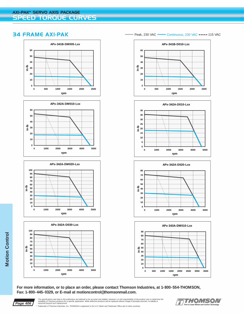
Page 406
AXI-PAK* SERVO AXIS PACKAGE
SPEED TORQUE CURVES
For more information, or to place an order, please contact Thomson Industries, at 1-800-554-THOMSON, Fax: 1-800-445-0329, or E-mail at [email protected].
The specifications and data in this publication are believed to be accurate and reliable. However, it is the responsibility of the product user to determine thesuitability of Thomson products for a specific application. While defective products will be replaced without charge if promptly returned, no liability isassumed beyond such replacement.
* Trademark of Thomson Industries, Inc. THOMSON is registered in the U.S. Patent and Trademark Office and in other countries.
Mo
tio
n C
ont
rol
34 FRAME AXI-PAK
APx-341B-DM005-Lxx
0
10
20
30
40
50
60
0 500 1000 1500 2000 2500
rpm
in-l
b
APx-342A-D010-Lxx
0
5
10
15
20
25
30
35
40
0 1000 2000 3000 4000 5000
rpm
in-l
b
APx-342A-D030-Lxx
0
10
20
30
40
50
60
70
80
90
100
0 1000 2000 3000 4000 5000
rpm
in-l
b
APx-342A-DM020-Lxx
0
10
20
30
40
50
60
70
80
90
100
0 1000 2000 3000 4000 5000
rpm
in-l
b
APx-341B-D010-Lxx
0
10
20
30
40
50
60
0 500 1000 1500 2000 2500
rpm
in-l
b
APx-342A-D020-Lxx
0
10
20
30
40
50
60
70
80
0 1000 2000 3000 4000 5000
rpm
in-l
b
APx-342A-DM010-Lxx
0
10
20
30
40
50
60
0 1000 2000 3000 4000 5000
rpm
in-l
b
APx-343A-DM010-Lxx
0
10
20
30
40
50
60
70
80
90
0 500 1000 1500 2000 2500 3000 3500
rpm
in-l
b
Peak, 230 VAC Continuous, 230 VAC 115 VAC

Page 407
For more information, or to place an order, please contact Thomson Industries, at 1-800-554-THOMSON, Fax: 1-800-445-0329, or E-mail at [email protected].
AXI-PAK* SERVO AXIS PACKAGE
SPEED TORQUE CURVES
The specifications and data in this publication are believed to be accurate and reliable. However, it is the responsibility of the product user to determine thesuitability of Thomson products for a specific application. While defective products will be replaced without charge if promptly returned, no liability isassumed beyond such replacement.
* Trademark of Thomson Industries, Inc. THOMSON is registered in the U.S. Patent and Trademark Office and in other countries.
Mo
tion C
ontro
l
34 FRAME AXI-PAK
APx-343A-D010-Lxx
0
10
20
30
40
50
60
0 500 1000 1500 2000 2500 3000 3500
rpm
in-l
b
APx-343A-D020-Lxx
0
20
40
60
80
100
120
0 500 1000 1500 2000 2500 3000 3500
rpm
in-l
b
APx-343A-D030-Lxx
0
20
40
60
80
100
120
140
0 500 1000 1500 2000 2500 3000 3500
rpm
in-l
b
APx-343A-DM020-Lxx
0
20
40
60
80
100
120
140
0 500 1000 1500 2000 2500 3000 3500
rpm
in-l
b
Peak, 230 VAC Continuous, 230 VAC 115 VAC

APx-421B-D020-Lxx
0
20
40
60
80
100
120
140
160
180
0 500 1000 1500 2000
rpm
in-l
b
Page 408
AXI-PAK* SERVO AXIS PACKAGE
SPEED TORQUE CURVES
For more information, or to place an order, please contact Thomson Industries, at 1-800-554-THOMSON, Fax: 1-800-445-0329, or E-mail at [email protected].
The specifications and data in this publication are believed to be accurate and reliable. However, it is the responsibility of the product user to determine thesuitability of Thomson products for a specific application. While defective products will be replaced without charge if promptly returned, no liability isassumed beyond such replacement.
* Trademark of Thomson Industries, Inc. THOMSON is registered in the U.S. Patent and Trademark Office and in other countries.
Mo
tio
n C
ont
rol
42 FRAME AXI-PAK
APx-422A-D075-Lxx (1 phase)
0
50
100
150
200
250
0 500 1000 1500 2000 2500 3000 3500
rpm
in-l
b
APx-421B-DM010-Lxx
0
20
40
60
80
100
120
140
160
0 500 1000 1500 2000
rpm
in-l
b
APx-422A-D020-Lxx
0
20
40
60
80
100
120
0 500 1000 1500 2000 2500 3000 3500
rpm
in-l
b
APx-421B-D010-Lxx
0
20
40
60
80
100
120
0 500 1000 1500 2000
rpm
in-l
b
APx-421B-DM020-Lxx
0
20
40
60
80
100
120
140
160
180
0 500 1000 1500 2000
rpm
in-l
b
APx-422A-D030-Lxx
0
20
40
60
80
100
120
140
160
180
0 500 1000 1500 2000 2500 3000 3500
rpm
in-l
b
APx-422A-DM020-Lxx
0
20
40
60
80
100
120
140
160
180
0 500 1000 1500 2000 2500 3000 3500
rpm
in-l
b
Peak, 230 VAC Continuous, 230 VAC 115 VAC

Page 409
For more information, or to place an order, please contact Thomson Industries, at 1-800-554-THOMSON, Fax: 1-800-445-0329, or E-mail at [email protected].
AXI-PAK* SERVO AXIS PACKAGE
SPEED TORQUE CURVES
The specifications and data in this publication are believed to be accurate and reliable. However, it is the responsibility of the product user to determine thesuitability of Thomson products for a specific application. While defective products will be replaced without charge if promptly returned, no liability isassumed beyond such replacement.
* Trademark of Thomson Industries, Inc. THOMSON is registered in the U.S. Patent and Trademark Office and in other countries.
Mo
tion C
ontro
l
42 FRAME AXI-PAK
APx-423B-D020-Lxx
0
50
100
150
200
250
0 500 1000 1500 2000
rpm
in-l
b
APx-423A-D075-Lxx (3 phase)
0
50
100
150
200
250
300
350
400
0 500 1000 1500 2000 2500 3000 3500
rpmin
-lb
APx-423B-D075-Lxx (1 or 3 phase)
0
50
100
150
200
250
300
350
400
0 500 1000 1500 2000
rpm
in-l
b
APx-423A-D075-Lxx (1 phase)
0
50
100
150
200
250
300
0 500 1000 1500 2000 2500 3000 3500
rpm
in-l
b
APx-423B-D030-Lxx
0
50
100
150
200
250
300
350
0 500 1000 1500 2000
rpm
in-l
bAPx-423A-D030-Lxx
0
20
40
60
80
100
120
140
160
0 500 1000 1500 2000 2500 3000 3500
rpm
in-l
b
APx-423B-DM020-Lxx
0
50
100
150
200
250
300
350
0 500 1000 1500 2000
rpm
in-l
bAPx-422A-D075-Lxx
(3 phase)
0
50
100
150
200
250
0 500 1000 1500 2000 2500 3000 3500
rpm
in-l
b
Peak, 230 VAC Continuous, 230 VAC

Page 410
AXI-PAK* SERVO AXIS PACKAGE
SPEED TORQUE CURVES
For more information, or to place an order, please contact Thomson Industries, at 1-800-554-THOMSON, Fax: 1-800-445-0329, or E-mail at [email protected].
The specifications and data in this publication are believed to be accurate and reliable. However, it is the responsibility of the product user to determine thesuitability of Thomson products for a specific application. While defective products will be replaced without charge if promptly returned, no liability isassumed beyond such replacement.
* Trademark of Thomson Industries, Inc. THOMSON is registered in the U.S. Patent and Trademark Office and in other countries.
Mo
tio
n C
ont
rol
60 FRAME AXI-PAK
APx-602B-D075-Lxx (1 phase)
0
100
200
300
400
500
600
0 500 1000 1500 2000
rpm
in-l
b
APx-602B-D075-Lxx (3 phase)
0
100
200
300
400
500
600
700
0 500 1000 1500 2000
rpm
in-l
b
APx-603A-D150-Lxx
0
100
200
300
400
500
600
700
800
900
0 500 1000 1500 2000 2500 3000
rpm
in-l
b
APx-602B-D030-Lxx
0
50
100
150
200
250
300
350
400
0 500 1000 1500 2000
rpm
in-l
b
APx-603A-D075-Lxx (3 phase)
0
100
200
300
400
500
600
0 500 1000 1500 2000 2500 3000
rpm
in-l
b
Peak, 230 VAC Continuous, 230 VAC

Page 411
For more information, or to place an order, please contact Thomson Industries, at 1-800-554-THOMSON, Fax: 1-800-445-0329, or E-mail at [email protected].
AXI-PAK* SERVO AXIS PACKAGE
ACCESSORIES
The specifications and data in this publication are believed to be accurate and reliable. However, it is the responsibility of the product user to determine thesuitability of Thomson products for a specific application. While defective products will be replaced without charge if promptly returned, no liability isassumed beyond such replacement.
* Trademark of Thomson Industries, Inc. THOMSON is registered in the U.S. Patent and Trademark Office and in other countries.
Mo
tion C
ontro
l
Dimensions and SpecificationsFor details on motors used in an AXI-PAK servo axis package, see the BLX Brushless Motor section starting on page 53.
For details on Servo Drives used in an AXI-PAK servo axis package, see theOMNIDRIVE* section starting on page 35.
Accessories
Touchpad TP-001
The optional Touchpad gives you the convenience of OMNI LINK* software inthe palm of your hand. The Touchpad plugs into the RS-232/RS-485 port onthe drive. One Touchpad communicates with all drive types. The Touchpadscan be left attached to the drive for constant operator use, or in a toolbox to be used as needed. The Touchpad is the best solution for maintenancetechnicians and engineers troubleshooting and testing on the floor.
Touchpad commands are entered by pressing a single key or combination ofkeys. Two modes of operation are available. Display mode allows you tomove through the touchpad command tree to each parameter. Modify modeallows you to monitor and change each parameter. Most parameters can bemodified or viewed while the drive is running or disabled.
Cables
Professionally molded, high quality cable assemblies just drop in, saving youtime and worry. Our cables incorporate features such as 360° shielding of bothcable and connectors for EMC compliance, UL approved oil and chemicalresistant cable, and fully molded connector housings with integral strain reliefs.
21365B Cable for direct connection of any AXI-PAK servo axis pack-age to the TMC-2000 motion controller. 36” length
21210B Cable, same as above 21365B with the addition of a separatepigtail to access all signals of the OMNIDRIVE digital servodrive that are unused by the TMC-2000 motion controller.
21380B10 Serial interface cable for connection to a PC or any RS-232/RS-485. 10ft. length. Note: one serial interface cableis included in each AXI-PAK servo axis package.
21468B-xx J1 interface cable. Available in lengths of 10 ft (xx=10) and 25 ft (xx=25). Note: one 10 ft cable is included in each AXI-PAK with indexing.
TOUCHPAD TP-001
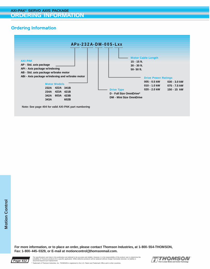
Page 412
AXI-PAK* SERVO AXIS PACKAGE
ORDERING INFORMATION
For more information, or to place an order, please contact Thomson Industries, at 1-800-554-THOMSON, Fax: 1-800-445-0329, or E-mail at [email protected].
The specifications and data in this publication are believed to be accurate and reliable. However, it is the responsibility of the product user to determine thesuitability of Thomson products for a specific application. While defective products will be replaced without charge if promptly returned, no liability isassumed beyond such replacement.
* Trademark of Thomson Industries, Inc. THOMSON is registered in the U.S. Patent and Trademark Office and in other countries.
Mo
tio
n C
ont
rol
APx-232A-DM-005-Lxx
030 - 3.0 kW075 - 7.5 kW150 - 15 kW
Note: See page 404 for valid AXI-PAK part numbering
AXI-PAKAP - Std. axis packageAPi - Axis package w/indexingAB - Std. axis package w/brake motorABi - Axis package w/indexing and w/brake motor
Motor Cable Length15 - 15 ft.30 - 30 ft.50- 50 ft.
Drive TypeD - Full Size OmniDrive* DM - Mini Size OmniDrive
Drive Power Ratings005 - 0.5 kW010 - 1.0 kW020 - 2.0 kW422A
423A603A
341B421B423B602B
Motor Models232A234A342A343A
Ordering Information

The specifications and data in this publication are believed to be accurate and reliable. However, it is the responsibility of the product user to determine thesuitability of Thomson products for a specific application. While defective products will be replaced without charge if promptly returned, no liability isassumed beyond such replacement.
* Trademark of Thomson Industries, Inc. THOMSON is registered in the U.S. Patent and Trademark Office and in other countries.
FEATURES
■ High performance microcontroller technology provides fully digital velocity,position, and current loop control as well as motor commutation
■ Software configurable for various modesincluding analog velocity and torque,encoder follower, step/direction, presetvelocities, and serial commands
■ Indexing versions are capable of storingmultiple move profiles for basic stand alonepositioning applications
■ Includes OMNI LINK Windows® based setup software – no programming language to learn!
■ Output power ratings from 0.5kW to 15kW
■ User configurable optically isolated I/O
■ Available in both space saving mini and full size versions
The Thomson OMNIDRIVE line of
digital brushless servo drives delivers the
high performance and reliability required
for any motion control application. Available
in continuous output power ratings from
0.5 kW to 15 kW, an OMNIDRIVE digital
servo drive flexibility allows it to be config-
ured for various command sources for
operation with a separate motion controller,
PLC, or as a stand alone drive or positioner.
The setup, operation, and control of an
OMNIDRIVE is just a point and click away
with full featured Windows¨ based OMNI
LINK* software or the available touchpad.
There is no programming language to learn.
For Application Engineering assistance contact the Thomson Technical HelpLine at 1-800-554-8466.* Trademark of Thomson Industries, Inc. THOMSON is registered in the U.S. Patent and Trademark Office and in other countries. Page 413
OMNIDRIVE* DIGITAL SERVO DRIVE
Mo
tion C
ontro
l
Page 414
OMNIDRIVE* DIGITAL SERVO DRIVE
FEATURES
For more information, or to place an order, please contact Thomson Industries, at 1-800-554-THOMSON, Fax: 1-800-445-0329, or E-mail at [email protected].
The specifications and data in this publication are believed to be accurate and reliable. However, it is the responsibility of the product user to determine thesuitability of Thomson products for a specific application. While defective products will be replaced without charge if promptly returned, no liability isassumed beyond such replacement.
* Trademark of Thomson Industries, Inc. THOMSON is registered in the U.S. Patent and Trademark Office and in other countries.
Mo
tio
n C
ont
rol
A Fully Digital Design Gives Unrivaled Functionality and Performance
OMNIDRIVE digital servo drives incorporate high performance micro-controllers giving the features, flexibility, performance, and ease of use onlypossible in a fully digital design. An OMNIDRIVE can be configured to control a brushless servo motor in conjunction with a separate motion controller, PLC, or as a stand alone drive or positioner. All aspects of configuration, adjustments, and diagnostics are done completely in software. Current, velocity, and position loops are controlled digitally, aswell as motor commutation. Intelligent Power Module (IPM) technologybased on the latest generation IGBTs provides the highest possible reliability. Brushless motors are controlled with a pulse width modulated(PWM) sine wave in a smooth and efficient method utilizing feedback froma motor mounted encoder. Onboard electrically erasable programmableread only memory (EEPROM) stores all motor and configuration parametersto ensure reliability and repeatability over time and temperature.
Multiple Command Sources
■ +/- 10V analog input for torque, velocity, or position modes
■ Step/Direction input or step up/step down with electronic gearing for a highperformance replacement for step motors
■ Auxiliary master encoder input with electronic gearing
■ Eight preset torques or speeds selected via the digital inputs
■ Basic positioning capability through eight preset move profiles and a homing routine (indexing version only)
■ RS-232/RS-485 serial host command language control for unlimited torque,velocity, position, and configuration control
■ Command source and mode of operation may be changed during operationby toggling of an input
An Easy to Use Package
All sizes of the OMNIDIVE digital servo drive share the same connectors for commonality. All connector locations are clearly marked on the front panel.Electronics and power supplies are fully enclosed in a single panel mountedpackage, eliminating the need for external transformers.
Host Command Language
A serial port provides the connection for the OMNIDRIVE to PCs, PLCs, orother smart systems that can communicate via a RS-232/RS-485 interface.The host command language is a rich serial command set which allows realtime control of multiple drives up to 32 addresses. The command languagegives remote access to all OMNIDRIVE parameters and functions.
Flexible I/O
Optically isolated digital inputs and outputs work with 12-24VDC and are userdefinable for various functions.

Page 415
For more information, or to place an order, please contact Thomson Industries, at 1-800-554-THOMSON, Fax: 1-800-445-0329, or E-mail at [email protected].
OMNIDRIVE* DIGITAL SERVO DRIVE
FEATURES
The specifications and data in this publication are believed to be accurate and reliable. However, it is the responsibility of the product user to determine thesuitability of Thomson products for a specific application. While defective products will be replaced without charge if promptly returned, no liability isassumed beyond such replacement.
* Trademark of Thomson Industries, Inc. THOMSON is registered in the U.S. Patent and Trademark Office and in other countries.
Mo
tion C
ontro
l
Choose the Mini Size when:
■ power levels are 0.5kW to 2kW
■ space is a premium
■ a more cost effective solution is needed
■ any application requires a feature rich, high performance, digital servo drive
Choose the Full Size when:
■ power levels are 1kW to 15 kW
■ internal shunt is needed for fast deceleration and high inertia applications
■ the most flexibility is required by a second serial port and a few extra I/O
■ any application requires a feature rich, high performance, digital servo drive
Multiple Protection Features
Multiple protection circuits monitor all critical parameters so in the unlikelyevent of trouble, your system shuts down safely and predictably. OMNI LINK*software provides a fault history which stores error messages allowing you toeasily troubleshoot what went wrong. OMNIDRIVE digital servo drives self-protect from input over/under voltage, phase to phase and phase to ground short circuit, overcurrent, drive and motor overtemperature, motoroverspeed, and various other errors. Additionally, watchdog timers provideadditional protection.
OMNIDRIVE Mini and OMNIDRIVE Full SizeTo satisfy the widest range of application requirements, OMNIDRIVE digital servo drivers are available in a full size version as well as a reduced size mini version.
Inputs may be configured as:
drive mode selectintegrator inhibitfollower enableforward enablereverse enable mode override
preset/index selectstart index
define homestart homing
fault resetregistration sensor
Outputs may be configured as:
in positionwithin windowzero speedspeed windowcurrent limitup to speeddrive enabledbus chargeddisabling faultin motionin dwellsequence completeregisteredat home
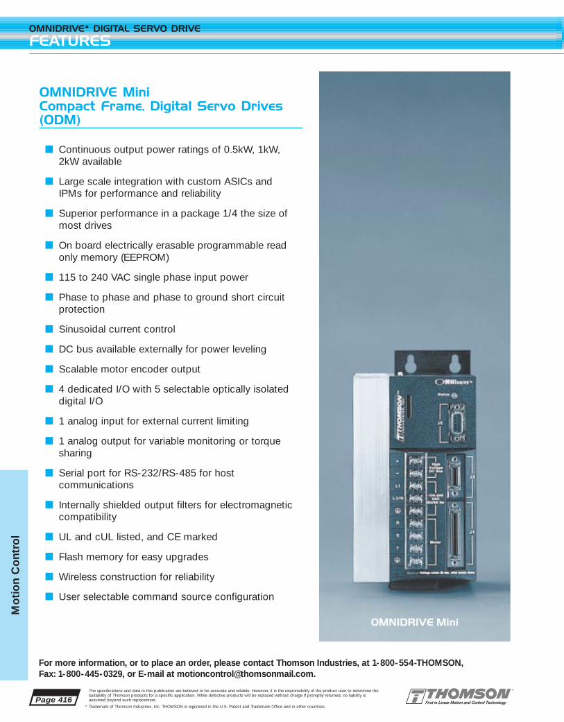
Page 416
OMNIDRIVE* DIGITAL SERVO DRIVE
FEATURES
For more information, or to place an order, please contact Thomson Industries, at 1-800-554-THOMSON, Fax: 1-800-445-0329, or E-mail at [email protected].
The specifications and data in this publication are believed to be accurate and reliable. However, it is the responsibility of the product user to determine thesuitability of Thomson products for a specific application. While defective products will be replaced without charge if promptly returned, no liability isassumed beyond such replacement.
* Trademark of Thomson Industries, Inc. THOMSON is registered in the U.S. Patent and Trademark Office and in other countries.
Mo
tio
n C
ont
rol
OMNIDRIVE Mini Compact Frame, Digital Servo Drives(ODM)
■ Continuous output power ratings of 0.5kW, 1kW,2kW available
■ Large scale integration with custom ASICs andIPMs for performance and reliability
■ Superior performance in a package 1/4 the size ofmost drives
■ On board electrically erasable programmable readonly memory (EEPROM)
■ 115 to 240 VAC single phase input power
■ Phase to phase and phase to ground short circuit protection
■ Sinusoidal current control
■ DC bus available externally for power leveling
■ Scalable motor encoder output
■ 4 dedicated I/O with 5 selectable optically isolated digital I/O
■ 1 analog input for external current limiting
■ 1 analog output for variable monitoring or torquesharing
■ Serial port for RS-232/RS-485 for host communications
■ Internally shielded output filters for electromagnetic compatibility
■ UL and cUL listed, and CE marked
■ Flash memory for easy upgrades
■ Wireless construction for reliability
■ User selectable command source configuration
OMNIDRIVE Mini

Page 417
For more information, or to place an order, please contact Thomson Industries, at 1-800-554-THOMSON, Fax: 1-800-445-0329, or E-mail at [email protected].
OMNIDRIVE* DIGITAL SERVO DRIVE
FEATURES
The specifications and data in this publication are believed to be accurate and reliable. However, it is the responsibility of the product user to determine thesuitability of Thomson products for a specific application. While defective products will be replaced without charge if promptly returned, no liability isassumed beyond such replacement.
* Trademark of Thomson Industries, Inc. THOMSON is registered in the U.S. Patent and Trademark Office and in other countries.
Mo
tion C
ontro
l
OMNIDRIVE Full SizeFull Featured Digital Servo Drives (OD)
■ Continuous output power ratings of 1kW, 2kW,3kW, 7.5kW, 15kW available
■ Advanced multi-processor design for all digital current, velocity and position loops
■ On board electrically erasable programmable readonly memory (EEPROM)
■ 115 to 240 VAC input power single phase(for OD-075 and OD-150 max power with 3 phase)
■ Phase to phase and phase to ground short circuit protection
■ Internal power supplies including a 24 V I/O supply, only AC line required
■ Sinusoidal current control
■ Removable personality module to store setup parameters
■ Large scale integration with custom ASICs andIPMs for performance and reliability
■ Flash memory for easy upgrades
■ DC bus available externally for power leveling
■ Scalable motor encoder output
■ 4 dedicated I/O with 8 selectable optically isolated digital I/O
■ 2 analog input for external current limiting
■ 2 analog output for variable monitoring or torquesharing
■ 2 serial ports for RS-232/RS-485 host communications
■ Internally shielded output filters for electromagnetic compatibility
■ Wireless construction for reliability
■ Internal or external resistive shunt
■ UL and cUL listed, and CE marked
OMNIDRIVE Full Size
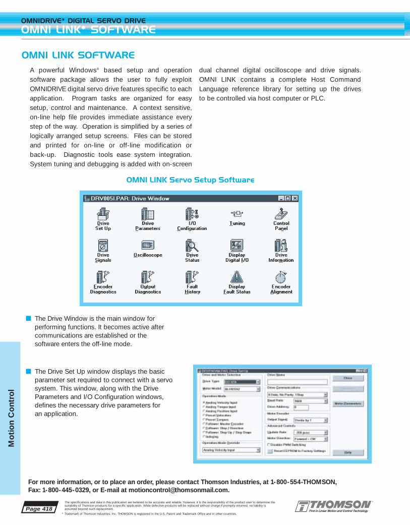
Page 418
OMNIDRIVE* DIGITAL SERVO DRIVE
OMNI LINK* SOFTWARE
For more information, or to place an order, please contact Thomson Industries, at 1-800-554-THOMSON, Fax: 1-800-445-0329, or E-mail at [email protected].
The specifications and data in this publication are believed to be accurate and reliable. However, it is the responsibility of the product user to determine thesuitability of Thomson products for a specific application. While defective products will be replaced without charge if promptly returned, no liability isassumed beyond such replacement.
* Trademark of Thomson Industries, Inc. THOMSON is registered in the U.S. Patent and Trademark Office and in other countries.
Mo
tio
n C
ont
rol
OMNI LINK SOFTWARE
OMNI LINK Servo Setup Software
■ The Drive Window is the main window for performing functions. It becomes active after communications are established or the software enters the off-line mode.
■ The Drive Set Up window displays the basic parameter set required to connect with a servosystem. This window, along with the DriveParameters and I/O Configuration windows,defines the necessary drive parameters for an application.
A powerful Windows® based setup and operation software package allows the user to fully exploitOMNIDRIVE digital servo drive features specific to eachapplication. Program tasks are organized for easysetup, control and maintenance. A context sensitive, on-line help file provides immediate assistance everystep of the way. Operation is simplified by a series oflogically arranged setup screens. Files can be storedand printed for on-line or off-line modification or back-up. Diagnostic tools ease system integration.System tuning and debugging is added with on-screen
dual channel digital oscilloscope and drive signals.OMNI LINK contains a complete Host CommandLanguage reference library for setting up the drives to be controlled via host computer or PLC.

Page 419
For more information, or to place an order, please contact Thomson Industries, at 1-800-554-THOMSON, Fax: 1-800-445-0329, or E-mail at [email protected].
OMNIDRIVE* DIGITAL SERVO DRIVE
OMNI LINK* SOFTWARE
The specifications and data in this publication are believed to be accurate and reliable. However, it is the responsibility of the product user to determine thesuitability of Thomson products for a specific application. While defective products will be replaced without charge if promptly returned, no liability isassumed beyond such replacement.
* Trademark of Thomson Industries, Inc. THOMSON is registered in the U.S. Patent and Trademark Office and in other countries.
Mo
tion C
ontro
l
■ The I/O Configuration window routes signals from digital inputs, assigns drivesignals to digital or analog outputs, andsets both active and inactive BRAKEdelays. This window, along with the DriveSet Up and the Drive Parameters windows,define the necessary drive parameters foran application.
■ The Tuning window displays the connecteddrive’s velocity and position servo loopgains. It provides various means for tuningthe servo loops and monitoring drive performance.
■ The Control Panel window is used as a set up and testing tool to verify that the drive isfunctioning.
■ The Oscilloscope window, along with theDrive Signals window, display the values ofselected drive signals in the connecteddrive.
■ The Encoder Diagnostics window is usedfor diagnosing encoder problems. It is usedto display the count from the motorencoder, the resolution and the position ofthe encoder index. If the drive’s OperationMode is set to Step/Direction or StepUp/Step Down, it also displays the countfrom the master input. If the drive’sOperation Mode is set to Master Encoder,it also displays the count from the masterencoder, the resolution and the position ofthe encoder index.
■ The Output Diagnostics window providescontrolled outputs for verification of analogand digital output signals. When this window is opened, the drive firmwareenters a special mode where the outputsare controlled by this window, rather thanby the state of the drive.
■ The Fault History window displays thefaults that are stored in the drive’s non-volatile memory. The fault list is arrangedfrom the most recent to the least recent.
■ The Fault Status window displays the stateof various potential fault sources. Faultswhich are active appear “lighted.” Refer tothe troubleshooting guide in the Hardwareand Installation Manual for determining thecause and appropriate actions.

Page 420
OMNIDRIVE* DIGITAL SERVO DRIVE
INDEXING OPTIONS
For more information, or to place an order, please contact Thomson Industries, at 1-800-554-THOMSON, Fax: 1-800-445-0329, or E-mail at [email protected].
The specifications and data in this publication are believed to be accurate and reliable. However, it is the responsibility of the product user to determine thesuitability of Thomson products for a specific application. While defective products will be replaced without charge if promptly returned, no liability isassumed beyond such replacement.
* Trademark of Thomson Industries, Inc. THOMSON is registered in the U.S. Patent and Trademark Office and in other countries.
Mo
tio
n C
ont
rol
INDEXING OPTION
When not using an AXI-PAK* digital servo drive in conjunction with a separate motion controller, you’lllikely be interested in the indexing option. This indexingcapability allows an AXI-PAK to act as a simple controller for basic point to point positioning applica-tions. Using the OMNI LINK* setup software, the drivemay be configured for up to eight different positionmoves (indexes) initiated by the drive’s digital I/O. Asthe OMNI LINK software only requires you to enterparameters in existing fields, there is no programminglanguage to learn. The moves may be incremental (a distance relative to the current position), absolute (a distance relative to home position) or registration
(a distance relative to the registration sensor input).Velocity, acceleration, and move distance may be specified for each index, as well as a batch count thatwill automatically repeat any index a specified numberof times. A dwell time between moves may also be set.Through an “action when complete” setting, each indexmay be linked to any other for automatic subsequentexecution. And for those cases where a host computeris employed, an infinite number of moves may be executed by sending parameter information to the drivevia the serial interface. The indexing option alsoincludes a user defined homing routine.
No Programming Language to Learn!
Up to eight indexes are defined using OMNI LINK setup soft-ware with a simple point and click. Absolute, relative, andregistration moves are supported. Moves are initiated by thedrive’s digital I/O.
User Defined Homing Routine
You can home to a sensor switch and/or encoder marker, aswell as set homing speed and acceleration, and enter a offsetdistance. Homing may begin automatically upon drive enableor through an assignable input.

Page 421
For more information, or to place an order, please contact Thomson Industries, at 1-800-554-THOMSON, Fax: 1-800-445-0329, or E-mail at [email protected].
OMNIDRIVE* DIGITAL SERVO DRIVE
SPECIFICATIONS
The specifications and data in this publication are believed to be accurate and reliable. However, it is the responsibility of the product user to determine thesuitability of Thomson products for a specific application. While defective products will be replaced without charge if promptly returned, no liability isassumed beyond such replacement.
* Trademark of Thomson Industries, Inc. THOMSON is registered in the U.S. Patent and Trademark Office and in other countries.
Mo
tion C
ontro
l
SERIAL COMMUNICATION PORT (ALL DRIVES)
RS-232, Four wire RS-4851200-19200 Baud rateMaximum 32 drives connected for multiple drive addressing
INTERNAL POWER SUPPLY SPECIFICATIONS
OD-010/020/030/075 Min Max Max Output Current
24 Vdc power supply 21.6 26.4 500 mA5 Vdc power supply 4.75 5.25 250 mA
ENVIRONMENTAL
Operating Temperature -5°C to 55°CHumidity 5% to 90% non-condensingAltitude 1500m/5000ftVibration 10 to 2000 Hz at 2gShock 15g 11msec half sine
OD-010/020/030/075/150 I/O (FULL SIZE)
4 Digital INPUTS4 Digital OUTPUTSDedicated Digital ENABLE InputDedicated Digital FAULT RESETDedicated BRAKE and DRIVE READY Relay Outputs2 External Current Limit Analog Input 0–10 volt2 User Set Analog Output +/-10 vEncoder Output Scalable by 1, 1/2, 1/4, 1/8
SELECTABLE I/O
Inputs and outputs are configurable in software as follows:
Selectable Outputs Selectable Inputs
In Position Drive Mode SelectWithin Window Integrator InhibitZero Speed Forward EnableSpeed Window Follower EnableCurrent Limit Reverse EnableUp to Speed Operation Mode OverrideDrive Enabled Preset Select 0–7Bus Charged Start IndexDisabling Fault Define HomeIn Motion Remove Command OffsetIn Dwell Registration SensorSequence CompleteRegisteredAt Home
ODM-005/010/020 I/O (MINI SIZE)
3 Selectable Digital INPUTS2 Selectable Digital OUTPUTSDedicated Digital ENABLE InputDedicated Digital FAULT RESETDedicated BRAKE and DRIVE READY Relay Outputs1 External Current Limit Analog Input 0–10 volt1 User Set Analog Output +/-10 vEncoder Output Scalable by 1, 1/2, 1/4, 1/8

Page 422
OMNIDRIVE* DIGITAL SERVO DRIVE
SPECIFICATIONS
For more information, or to place an order, please contact Thomson Industries, at 1-800-554-THOMSON, Fax: 1-800-445-0329, or E-mail at [email protected].
The specifications and data in this publication are believed to be accurate and reliable. However, it is the responsibility of the product user to determine thesuitability of Thomson products for a specific application. While defective products will be replaced without charge if promptly returned, no liability isassumed beyond such replacement.
* Trademark of Thomson Industries, Inc. THOMSON is registered in the U.S. Patent and Trademark Office and in other countries.
Mo
tio
n C
ont
rol
MIN I
ODM-005 ODM-010 ODM-020
Peak Output 7.5 Amps 15 Amps 30 AmpsCurrent (Amps)
Continuous Output 2.5 Amps 5 Amps 10 AmpsCurrent (Amps)
Continuous Output 0.5 kW 1 kW 2 kWPower (kW)
Continuous Input 5 9 18Current (Amps)
Input Voltage 100 to 240 VAC 100 to 240 VAC 100 to 240 VACand Frequency 47-63 Hz 47-63 Hz 47-63 Hz
Velocity Loop 300 Hz 300 Hz 300 HzBandwidth Maximum
Weight Lbs (kg) 3.7 (1.68) 4.5 (2.03) 4.4 (2.0)
FULL S IZE
OD-010 OD-020 OD-030 OD-075 OD-075 OD-150Single Phase Three Phase Three Phase
Input Input Input
Peak Output 10 Amps 20 Amps 30 Amps 50 Amps 75 Amps 150 AmpsCurrent (Amps)
Continuous Output 5 Amps 10 Amps 15 Amps 15 Amps 35 Amps 65 AmpsCurrent (Amps)
Continuous Output 1 kW 2 kW 3 kW 3 kW 7.5 kW 15 kWPower (kW)
Continuous Input 19 28 28 28 30 46Current (Amps)
Input Voltage 100-240 VAC 100-240 VAC 100-240 VAC 100-240 VAC 100-240 VAC 100-240 VACand Frequency 47-63 Hz 47-63 Hz 47-63 Hz 47-63 Hz 47-63 Hz 47-63 Hz
Velocity Loop 400 Hz 400 Hz 400 Hz 400 Hz 400 Hz 400 HzBandwidth Maximum
Weight Lbs (kg) 12.8 (5.80) 14 (6.36) 14.3 (6.48) 21.3 (9.67) 21.3 (9.67) 31 (14.06)

Page 423
For more information, or to place an order, please contact Thomson Industries, at 1-800-554-THOMSON, Fax: 1-800-445-0329, or E-mail at [email protected].
OMNIDRIVE* DIGITAL SERVO DRIVE
CONNECTOR PINOUTS
The specifications and data in this publication are believed to be accurate and reliable. However, it is the responsibility of the product user to determine thesuitability of Thomson products for a specific application. While defective products will be replaced without charge if promptly returned, no liability isassumed beyond such replacement.
* Trademark of Thomson Industries, Inc. THOMSON is registered in the U.S. Patent and Trademark Office and in other countries.
Mo
tion C
ontro
l
J5 - Serial Port
Pin Function
1 RCV + RS-4852 RCV RS-2323 XMT RS-2324 XMT + RS-4855 COM6 Reserved7 RCV - RS-4858 XMT - RS-4859 Reserved
J2 - Encoder
Pin Function
1 Encoder +5V Pwr2 Encoder VCOM3 Encoder +5V Pwr4 Encoder VCOM5 Reserved6 Reserved7 Mtr Encdr Input Chnl A+8 Mtr Encdr Input Chnl A-9 Mtr Encdr Input Chnl B+10 Mtr Encdr Input Chnl B-
Pin Function
11 Mtr Encdr Input Chnl I+12 Mtr Encdr Input Chnl I-13 Hall A14 Hall B15 Hall C16 Absolute Position17 Reserved18 Reserved19 Thermal Switch +20 Thermal Switch -
J1 - Controller
Pin Function
1 Encoder +5VDC2 Encoder COM3 Encoder +5VDC4 Encoder COM5 External +24 VDC6 External 24VCOM7 Mtr Encdr Output Chnl A+8 Mtr Encdr Output Chnl A-9 Mtr Encdr Output Chnl B+10 Mtr Encdr Output Chnl B-11 Mtr Encdr Output Chnl I+12 Mtr Encdr Output Chnl I-13 External 24V Com
Pin Function
14 Auxiliary Chnl A+15 Auxiliary Chnl A-16 Auxiliary Chnl B+17 Auxiliary Chnl B-18 Auxiliary Chnl I+19 Auxiliary Chnl I-20 Drive Enable21 Fault Reset22 Analog Cmnd +23 Analog Cmnd -24 Drive Ready +25 Drive Ready -26 External +24 VDC
Pin Function
27 +I Limit28 Analog Com29 -I Limit30 Reserved31 Analog Output 132 Selectable Input 133 Selectable Input 234 Selectable Input 335 Reserved36 Reserved37 Reserved38 Reserved39 Reserved
Pin Function
40 Reserved41 Reserved42 Selectable Output 143 Selectable Output 244 Reserved45 Reserved46 Reserved47 Reserved48 Reserved49 Brake Enable +50 Brake Enable -
Pin Function
1 RCV + RS-4852 RCV RS-2323 XMT RS-2324 XMT + RS-4855 COM6 Reserved7 RCV - RS-4858 XMT - RS-4859 Reserved
J2 - Encoder
Pin Function
1 Encoder Pwr2 Encoder Com3 Encoder Pwr4 Encoder Com5 Encoder Pwr Sense +6 Encoder Pwr Sense -7 Mtr Encdr Input Chnl A+8 Mtr Encdr Input Chnl A-9 Mtr Encdr Input Chnl B+10 Mtr Encdr Input Chnl B-
Pin Function
11 Mtr Encdr Input Chnl I+12 Mtr Encdr Input Chnl I-13 Hall Effect A14 Hall Effect B15 Hall Effect C16 Absolute Position17 Reserved18 Reserved19 Thermal Switch +20 Thermal Switch -
J1 - Controller
Pin Function
1 Encoder +5V DC2 Encoder Com3 Encoder +5V DC4 Encoder Com5 External +24 VDC6 External 24V COM7 Mtr Output Chnl A+8 Mtr Output Chnl A-9 Mtr Output Chnl B+10 Mtr Output Chnl B-11 Mtr Output Chnl I+12 Mtr Output Chnl I-13 Isolated 24V Com
Pin Function
14 Auxiliary Chnl A+15 Auxiliary Chnl A-16 Auxiliary Chnl B+17 Auxiliary Chnl B-18 Auxiliary Chnl I+19 Auxiliary Chnl I-20 Drive Enable21 Fault Reset22 Analog Cmnd +23 Analog Cmnd -24 Drive Ready +25 Drive Ready -26 Isolated +24 VDC
Pin Function
27 +I Limit28 Analog Com29 -I Limit30 Analog Output 131 Analog Output 232 Selectable Input 133 Selectable Input 234 Selectable Input 335 Selectable Input 436 Reserved37 Reserved38 Reserved39 Reserved
Pin Function
40 Reserved41 Reserved42 Selectable Output 143 Selectable Output 244 Selectable Output 345 Selectable Output 446 Reserved47 Reserved48 Reserved49 Brake Enable +50 Brake Enable -
OD-010, OD-020, OD-030, OD-075, and OD-150
ODM-005, ODM010 and ODM-020
J4and J5 - Serial Port
Pin Function
Duplicates J1 pins 1–26
J3 - Auxiliary Port
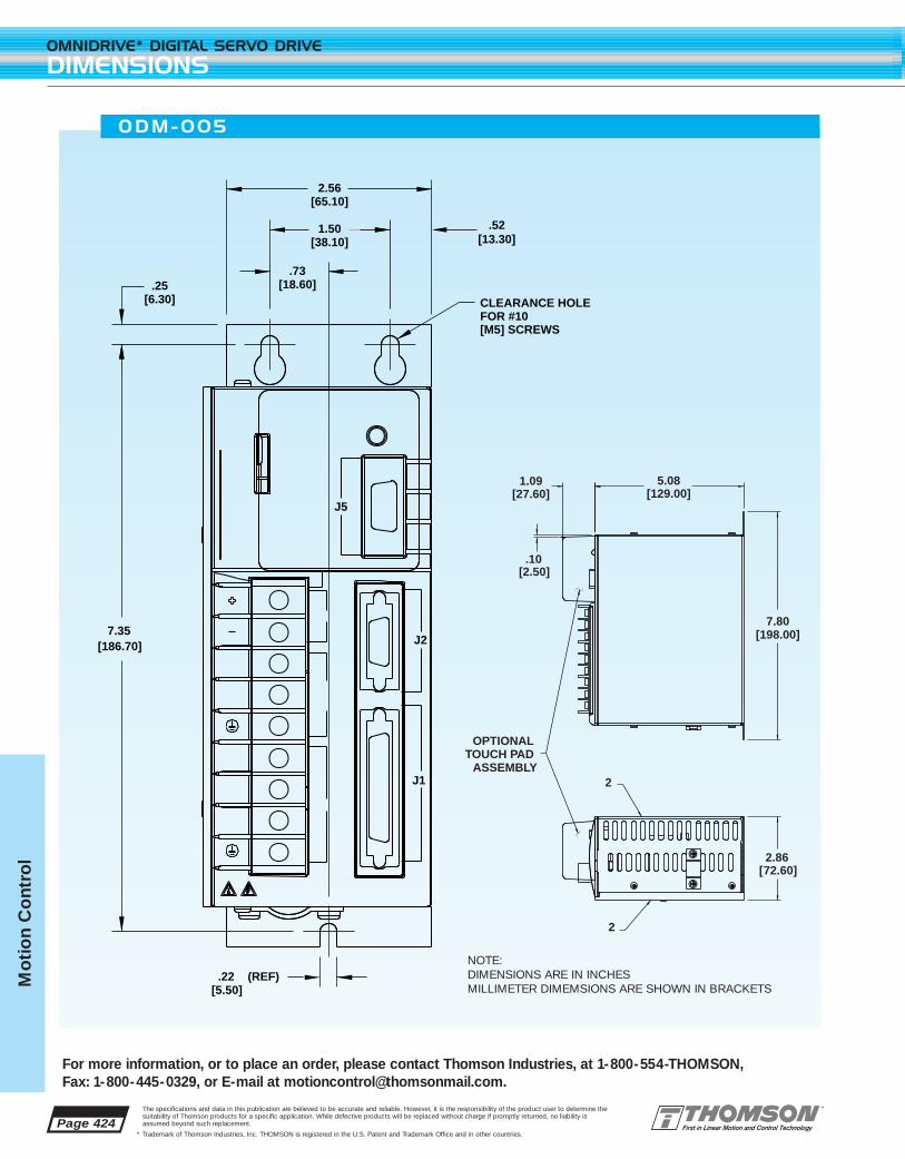
Page 424
OMNIDRIVE* DIGITAL SERVO DRIVE
DIMENSIONS
For more information, or to place an order, please contact Thomson Industries, at 1-800-554-THOMSON, Fax: 1-800-445-0329, or E-mail at [email protected].
The specifications and data in this publication are believed to be accurate and reliable. However, it is the responsibility of the product user to determine thesuitability of Thomson products for a specific application. While defective products will be replaced without charge if promptly returned, no liability isassumed beyond such replacement.
* Trademark of Thomson Industries, Inc. THOMSON is registered in the U.S. Patent and Trademark Office and in other countries.
Mo
tio
n C
ont
rol
[27.60]1.09
[129.00]5.08
[2.50].10
2
2
OPTIONAL TOUCH PAD
ASSEMBLY
[198.00]7.80
[72.60]2.86
[65.10]2.56
[13.30].52
J5
J2
J1
CLEARANCE HOLE FOR #10 [M5] SCREWS
[38.10]1.50
[18.60].73
[6.30].25
[186.70]7.35
[5.50].22 (REF)
ODM-005
NOTE:DIMENSIONS ARE IN INCHESMILLIMETER DIMEMSIONS ARE SHOWN IN BRACKETS

Page 425
For more information, or to place an order, please contact Thomson Industries, at 1-800-554-THOMSON, Fax: 1-800-445-0329, or E-mail at [email protected].
OMNIDRIVE* DIGITAL SERVO DRIVE
DIMENSIONS
The specifications and data in this publication are believed to be accurate and reliable. However, it is the responsibility of the product user to determine thesuitability of Thomson products for a specific application. While defective products will be replaced without charge if promptly returned, no liability isassumed beyond such replacement.
* Trademark of Thomson Industries, Inc. THOMSON is registered in the U.S. Patent and Trademark Office and in other countries.
Mo
tion C
ontro
l
OPTIONAL TOUCH PAD
ASSEMBLY
[27.60]1.09
[129.00]5.08
[2.40]
AIR EXHAUST
AIR INTAKE
.09
2
2 FAN ON ODM-020 ONLY
[198.00]7.80
[97.30]3.83
[13.30].52
CLEARANCE HOLE FOR #10[M5] SCREWS
[65.10]2.56
[38.10]1.50
[18.60].73
[6.30].25
[186.70]7.35
[5.50].22 (REF)
J5
J2
J1
ODM-0 10 AND ODM-020
NOTE:DIMENSIONS ARE IN INCHESMILLIMETER DIMEMSIONS ARE SHOWN IN BRACKETS

Page 426
OMNIDRIVE* DIGITAL SERVO DRIVE
DIMENSIONS
For more information, or to place an order, please contact Thomson Industries, at 1-800-554-THOMSON, Fax: 1-800-445-0329, or E-mail at [email protected].
The specifications and data in this publication are believed to be accurate and reliable. However, it is the responsibility of the product user to determine thesuitability of Thomson products for a specific application. While defective products will be replaced without charge if promptly returned, no liability isassumed beyond such replacement.
* Trademark of Thomson Industries, Inc. THOMSON is registered in the U.S. Patent and Trademark Office and in other countries.
Mo
tio
n C
ont
rol
13.75[349.3]
0.25[6.4]
14.20[360.6]
2.00[50.8]
1.00[25.4]
[104.1]4.10
1.05[26.6]
0
21
3456789ABCDEF
AUX
A 1
A 2
COM
L1 AUX
L1
L2/N
DC BUS-
L2/N
DC BUS+
DC BUS
MO
TOR
100-
240
VAC
50/
60 H
z
R
S
T
TB1
TB2
3
1
2
EX
TE
RN
AL
SH
UN
T
STATUS
INT
ER
NA
L
CLEARANCE HOLES FOR #10[M5] MOUNTING SCREWS
CO
NT
RO
LL
ER
SE
RIA
L 2
SE
RIA
L 1
AU
XIL
IAR
YM
OTO
R E
NC
OD
ER
J3
J4
J5
J2
J1
WARNING: HIGH VOLTAGE MAY EXIST UP TO FIVE MINUTES AFTER REMOVING POWER.
OMNIDRIVE
AIR
8.93[226.8]
EXHAUST
AIR INTAKE
OD-0 10 , OD -020 AND OD -030
NOTE:DIMENSIONS ARE IN INCHESMILLIMETER DIMEMSIONS ARE SHOWN IN BRACKETS
NOTE:DIMENSIONS ARE IN INCHESMILLIMETER DIMEMSIONS ARE SHOWN IN BRACKETS

Page 427
For more information, or to place an order, please contact Thomson Industries, at 1-800-554-THOMSON, Fax: 1-800-445-0329, or E-mail at [email protected].
OMNIDRIVE* DIGITAL SERVO DRIVE
DIMENSIONS
The specifications and data in this publication are believed to be accurate and reliable. However, it is the responsibility of the product user to determine thesuitability of Thomson products for a specific application. While defective products will be replaced without charge if promptly returned, no liability isassumed beyond such replacement.
* Trademark of Thomson Industries, Inc. THOMSON is registered in the U.S. Patent and Trademark Office and in other countries.
Mo
tion C
ontro
l
14.20[360.7]
0.27[7.0]
13.75[349.3]
1.99[50.5]
5.97[151.7]
1.00[25.4]
1.00[25.4]
AUXL2/N
A 1
A 2
COM
STATUS
L1 AUX
L1
L2/N
L3
DC BUS-
DC BUS+
DC BUS
MO
TOR
100-
240
VAC
50/
60 H
z
R
S
T
TB1
TB2
3
1
2
EX
TE
RN
AL
SH
UN
T
INT
ER
NA
L
00221133445566 77
8899
AABBCCDDEE
FF
CO
NT
RO
LL
ER
SE
RIA
L 2
SE
RIA
L 1
AU
XIL
IAR
YM
OTO
R E
NC
OD
ER
J3
J4
J5
J2
J1
WARNING: HIGH VOLTAGE MAY EXIST UP TO FIVE MINUTES AFTER REMOVING POWER.
OMNIDRIVE
8.84[224.5]
AIR INTAKE
AIR EXHAUST
AIR INTAKE
NOTE:DIMENSIONS ARE IN INCHESMILLIMETER DIMEMSIONS ARE SHOWN IN BRACKETS
OD-075
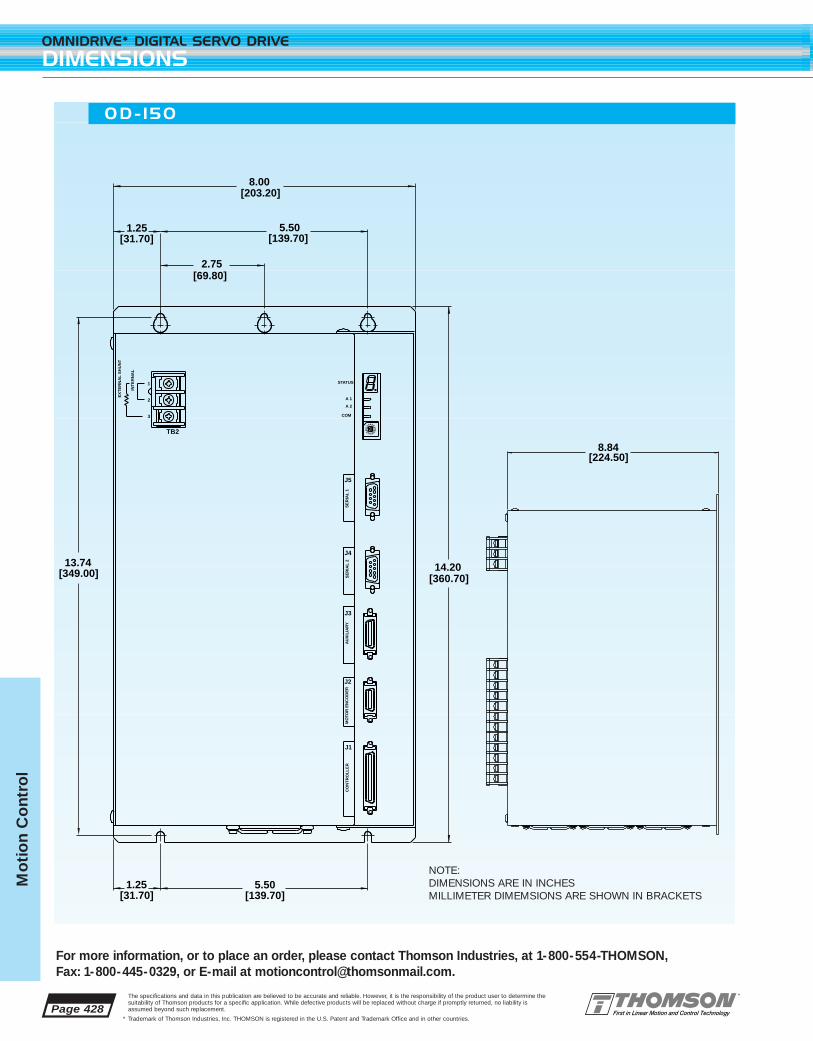
Page 428
OMNIDRIVE* DIGITAL SERVO DRIVE
DIMENSIONS
For more information, or to place an order, please contact Thomson Industries, at 1-800-554-THOMSON, Fax: 1-800-445-0329, or E-mail at [email protected].
The specifications and data in this publication are believed to be accurate and reliable. However, it is the responsibility of the product user to determine thesuitability of Thomson products for a specific application. While defective products will be replaced without charge if promptly returned, no liability isassumed beyond such replacement.
* Trademark of Thomson Industries, Inc. THOMSON is registered in the U.S. Patent and Trademark Office and in other countries.
Mo
tio
n C
ont
rol
5.50[139.70]
8.00[203.20]
2.75[69.80]
1.25[31.70]
14.20[360.70]
13.74[349.00]
1.25[31.70]
5.50[139.70]
3
EX
TE
RN
AL
SH
UN
T
1
2
INT
ER
NA
L
TB2
CO
NT
RO
LL
ER
J1
MO
TOR
EN
CO
DE
R
J2
AU
XIL
IAR
Y
J3
J4
SE
RIA
L 2
SE
RIA
L 1
J5
0
21
3456
78
9
ABCDE
F
A 1
A 2
COM
STATUS
8.84[224.50]
NOTE:DIMENSIONS ARE IN INCHESMILLIMETER DIMEMSIONS ARE SHOWN IN BRACKETS
OD- 150
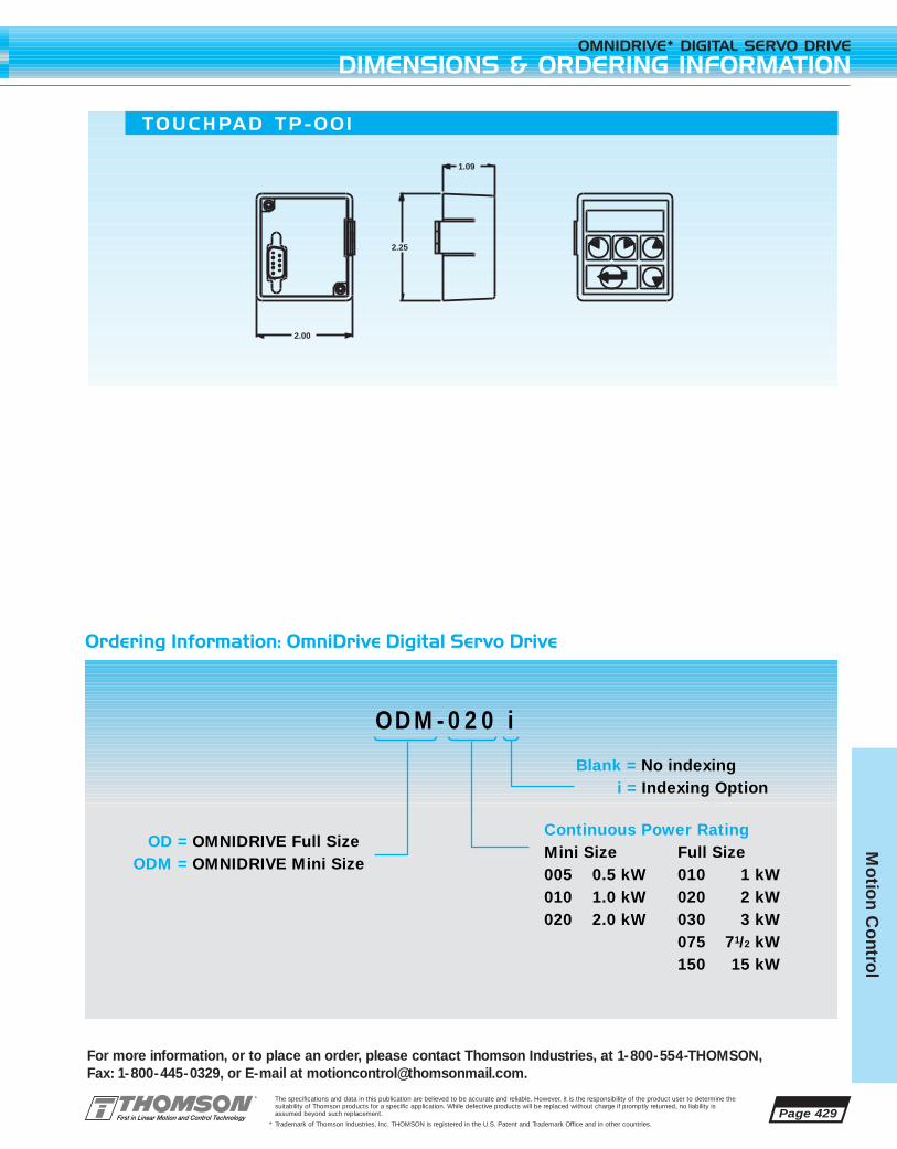
Page 429
For more information, or to place an order, please contact Thomson Industries, at 1-800-554-THOMSON, Fax: 1-800-445-0329, or E-mail at [email protected].
OMNIDRIVE* DIGITAL SERVO DRIVE
DIMENSIONS & ORDERING INFORMATION
The specifications and data in this publication are believed to be accurate and reliable. However, it is the responsibility of the product user to determine thesuitability of Thomson products for a specific application. While defective products will be replaced without charge if promptly returned, no liability isassumed beyond such replacement.
* Trademark of Thomson Industries, Inc. THOMSON is registered in the U.S. Patent and Trademark Office and in other countries.
Mo
tion C
ontro
l
Ordering Information: OmniDrive Digital Servo Drive
2.25
2.00
1.09
TOUCHPAD TP-00 1
ODM-020 i
OD = OMNIDRIVE Full SizeODM = OMNIDRIVE Mini Size
Blank = No indexing i = Indexing Option
Full Size010 1 kW020 2 kW030 3 kW075 71/2 kW150 15 kW
Continuous Power RatingMini Size005 0.5 kW010 1.0 kW020 2.0 kW

Page 430
OMNIDRIVE* DIGITAL SERVO DRIVE
ACCESSORIES
For more information, or to place an order, please contact Thomson Industries, at 1-800-554-THOMSON, Fax: 1-800-445-0329, or E-mail at [email protected].
The specifications and data in this publication are believed to be accurate and reliable. However, it is the responsibility of the product user to determine thesuitability of Thomson products for a specific application. While defective products will be replaced without charge if promptly returned, no liability isassumed beyond such replacement.
* Trademark of Thomson Industries, Inc. THOMSON is registered in the U.S. Patent and Trademark Office and in other countries.
Mo
tio
n C
ont
rol
AXI-PAK* Servo Axis Packages
Thomson Industries engineered AXI-PAK servo axispackages are proven combinations of OMNIDRIVEdigital dervo drives, BLX servo motors and cablingdesigned to deliver the best performing, lowest costsolutions for the widest variety of applications. Seepage 431 for details.
TouchPad P/N TP-001
The optional Touchpad gives you the flexibility and power of OMNI LINK* software in the palm of your hand. The Touchpad plugs into the RS-232/RS-485 port on the drive. One Touchpad communicates with all drivetypes. The Touchpads can be left attached to the drive for constant operatoruse or in a toolbox to be used as needed. The Touchpad is a convenient solu-tion for maintenance technicians and engineers troubleshooting and testing onthe floor.
Touchpad commands are entered by pressing a single key or combination ofkeys. Two modes of operation are available. Display mode allows you tomove through the touchpad command tree to each parameter. Modify modeallows you to monitor and change each parameter. Most parameters can bemodified or viewed while the drive is running or disabled.
CABLES
Professionally molded, high quality cable assemblies just drop in, saving youtime and worry. Our cables incorporate features such as 360° shielding of bothcable and connectors for EMC compliance, UL approved oil and chemicalresistant cable, and fully molded connector housings with integral strain reliefs.
21209B-xx Power/feedback cable for all BLX23 motors w/o brake21305B-xx Power/feedback cable for all BLX23 motors w/ brake21207B-xx Feedback cable for all BLX 34, 42, 60 motors21290B-xx Power cable for BLX 34x, 421, 422 motors w/o brake21206B-xx Power cable for BLX 34x, 421, 422 motors w/ brake21208B-xx Power cable for BLX 423, 60x motors w/o brake21306B-xx Power cable for BLX 423, 60x motors w/ brake21210B OMNIDRIVE to TMC-2000 interface w/breakout21365B OMNIDRIVE to TMC-2000 interface21380B10 RS232 serial cable, 10 ft21468B-xx J1 interface pigtail, xx= 10 ft. or 25 ft. only
xx = standard cable length designator, 15=15ft, 30=30ft, 50=50ft except for 21468B-xx which is10ft or 25ft only.

Mo
tion C
ontro
l
FEATURES
■ Four frame sizes to fit your requirements
■ High energy magnets for extremely high torque
■ Maintenance free brushless construction
■ Standard IP65 sealing for wash down environments
■ MS style connectors for durability
■ Internal 2000 line (8000 count) commutating encoder
■ Internal thermal switch
■ UL and cUL recognized
■ Optional internal 24VDC brake
■ Optional Thomson Micron True Planetary* gearheads
■ Available matching OMNIDRIVE digital servo drives and pre-made cables
■ Off-the-shelf delivery
The BLX Series of brushless servo motors are industrial quality motors designed for high
performance and durability. A superior magnetic and thermal design gives exceptional
performance and the highest torque per frame size. A wide variety of frame sizes and
winding configurations are available to suit your application needs.
BLX servo motors are built to last. Brushless construction and lifetime lubricated bearings
eliminate all maintenance issues. Standard IP65 sealing, MS style fluid tight connectors, over-
size bearings, and a winding thermal switch ensure a long and worry-free service life in the
harshest and most challenging applications.
For a complete motor control solution, BLX motors are available with matched OMNIDRIVE*
digital servo drives and pre-made cables for a quick, easy and trouble-free installation.
For Application Engineering assistance contact the Thomson Technical HelpLine at 1-800-554-8466.* Trademark of Thomson Industries, Inc. THOMSON is registered in the U.S. Patent and Trademark Office and in other countries. Page 431
BLX BRUSHLESS SERVO MOTORS

Page 432
BLX BRUSHLESS SERVO MOTORS
BLX 23 SERIES
For more information, or to place an order, please contact Thomson Industries, at 1-800-554-THOMSON, Fax: 1-800-445-0329, or E-mail at [email protected].
The specifications and data in this publication are believed to be accurate and reliable. However, it is the responsibility of the product user to determine thesuitability of Thomson products for a specific application. While defective products will be replaced without charge if promptly returned, no liability isassumed beyond such replacement.
* Trademark of Thomson Industries, Inc. THOMSON is registered in the U.S. Patent and Trademark Office and in other countries.
Mo
tio
n C
ont
rol NOTES:
1. With 230VAC drive line input voltage.2. 25°C ambient, motor mounted on a 8”x8”x1/2” aluminum heat sink and
the lower of 155°C winding or 100°C encoder temperature.3. Peak value of a sinusoidal waveform.4. Add brake inertia if applicable.COMMENTS:a) Thermostat in stator windings will open if
winding temperature exceeds 155°C.b) Above data represent typical values. Actual performance is dependent
on amplifier, controller, and system installed.
MOTOR DATA
PARAMETER SYMBOL UNITS BLX232A BLX234A
Rated Power (1)(2) Pr Hp 0.22 0.47
Kw 0.16 0.36
Speed at Rated Power N rated rpm 4000 5000
Max Operating Speed (1) N max rpm 5000 6500
Continuous Stall Torque (2) Tc in-lb 5 10
Nm 0.56 1.12
Peak Torque Tp in-lb 15 30
Nm 1.7 3.36
Rotor Inertia (4) Jm lb-in-s2 0.000097 0.000184
Kg-m2 0.0000109 0.0000207
Weight W lb 3 3.7
Kg 1.3 1.68
Number of Poles - - 4 4
Torque Constant, sinewave
(line-line) (3) Kt in-lb/A 1.81 1.81
Nm/A 0.204 0.204
Voltage Constant Ke Vrms /Krpm 18.2 17.8
(line-line)
Vrms /rad/sec 0.174 0.17
Resistance (cold) Rc ohm 8.4 3.1
(line-line)
Resistance (hot) Rh ohm 12.6 4.65
(line-line)
Inductance L mH 11.6 5.1
(line-line)
Peak Current (3) Ip A 8.28 18
Continuous Current (3) Ic A 2.76 6
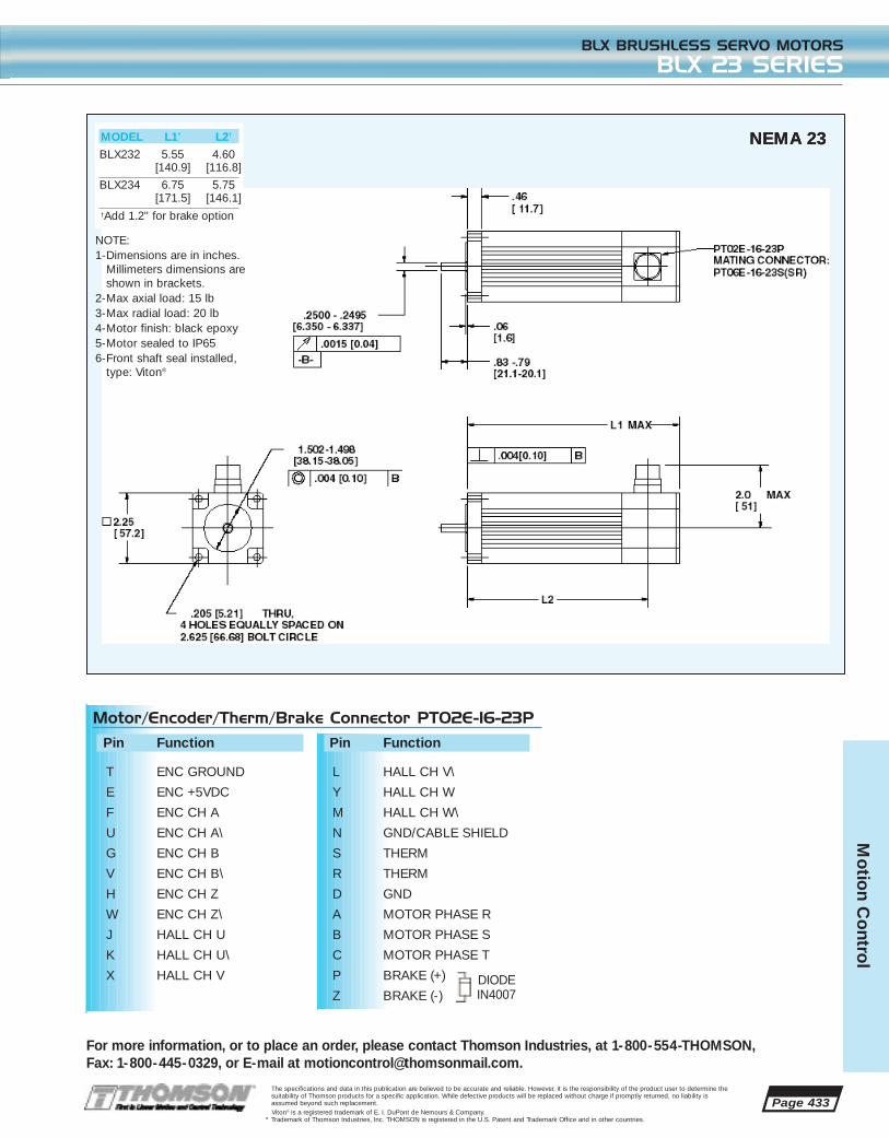
Page 433
For more information, or to place an order, please contact Thomson Industries, at 1-800-554-THOMSON, Fax: 1-800-445-0329, or E-mail at [email protected].
BLX BRUSHLESS SERVO MOTORS
BLX 23 SERIES
The specifications and data in this publication are believed to be accurate and reliable. However, it is the responsibility of the product user to determine thesuitability of Thomson products for a specific application. While defective products will be replaced without charge if promptly returned, no liability isassumed beyond such replacement.Viton® is a registered trademark of E. I. DuPont de Nemours & Company.
* Trademark of Thomson Industries, Inc. THOMSON is registered in the U.S. Patent and Trademark Office and in other countries.
Mo
tion C
ontro
l
MODEL L1† L2†
BLX232 5.55 4.60[140.9] [116.8]
BLX234 6.75 5.75[171.5] [146.1]
†Add 1.2" for brake option
DIODEIN4007
Motor/Encoder/Therm/Brake Connector PT02E-16-23P
Pin Function
T ENC GROUND
E ENC +5VDC
F ENC CH A
U ENC CH A\
G ENC CH B
V ENC CH B\
H ENC CH Z
W ENC CH Z\
J HALL CH U
K HALL CH U\
X HALL CH V
Pin Function
L HALL CH V\
Y HALL CH W
M HALL CH W\
N GND/CABLE SHIELD
S THERM
R THERM
D GND
A MOTOR PHASE R
B MOTOR PHASE S
C MOTOR PHASE T
P BRAKE (+)
Z BRAKE (-)
NOTE:1-Dimensions are in inches.
Millimeters dimensions areshown in brackets.
2-Max axial load: 15 lb3-Max radial load: 20 lb4-Motor finish: black epoxy5-Motor sealed to IP656-Front shaft seal installed,
type: Viton®
NEMA 23NEMA 23

Page 434
BLX BRUSHLESS SERVO MOTORS
BLX 34 SERIES
For more information, or to place an order, please contact Thomson Industries, at 1-800-554-THOMSON, Fax: 1-800-445-0329, or E-mail at [email protected].
The specifications and data in this publication are believed to be accurate and reliable. However, it is the responsibility of the product user to determine thesuitability of Thomson products for a specific application. While defective products will be replaced without charge if promptly returned, no liability isassumed beyond such replacement.
* Trademark of Thomson Industries, Inc. THOMSON is registered in the U.S. Patent and Trademark Office and in other countries.
Mo
tio
n C
ont
rol NOTES:
1. With 230VAC drive line input voltage.2. 25°C ambient, motor mounted on a 8"x 8"x 1/2" aluminum heat sink and
the lower of 155°C winding or 100°C encoder temperature.3. Peak value of a sinusoidal waveform.4. Add brake inertia if applicable.COMMENTS:a) Thermostat in stator windings will open if winding temperature exceeds
155°C.b) Above data represent typical values. Actual performance is dependent
on amplifier, controller, and system installed.
MOTOR DATA
PARAMETER SYMBOL UNITS BLX341B BLX342A BLX343A
Rated Power (1)(2) Pr Hp 0.55 1.62 1.96
Kw 0.41 1.20 1.46
Speed at Rated Power N rated rpm 2400 4000 3600
Max Operating Speed (1) N max rpm 3000 5000 4100
Continuous Stall Torque (2) Tc in-lb 16.0 30 39
Nm 1.81 3.4 4.4
Peak Torque Tp in-lb 48.0 90 117
Nm 5.43 10.2 13.2
Rotor Inertia (4) Jm lb-in-s2 0.000615 0.000991 0.00137
Kg-m2 0.0000693 0.0001116 0.000154
Weight W lb 8.3 9.3 14.6
Kg 3.8 4.2 6.6
Number of Poles - - 6 6 6
Torque Constant, sinewave Kt in-lb/A 7.65 3.91 5.58
( line-line) (3)
Nm/A 0.864 0.442 0.63
Voltage Constant Ke Vrms /Krpm 75.2 36.6 55
(line-line)
Vrms /rad/sec 0.72 0.35 0.53
Resistance (cold) Rc ohm 15.4 1.5 1.9
(line-line)
Resistance (hot) Rh ohm 23.1 2.25 2.85
(line-line)
Inductance L mH 39.6 5.1 7.5
(line-line)
Peak Current (3) Ip A 6.57 25.2 21.75
Continuous Current (3) Ic A 2.19 8.4 7.25

Page 435
For more information, or to place an order, please contact Thomson Industries, at 1-800-554-THOMSON, Fax: 1-800-445-0329, or E-mail at [email protected].
BLX BRUSHLESS SERVO MOTORS
BLX 34 SERIES
The specifications and data in this publication are believed to be accurate and reliable. However, it is the responsibility of the product user to determine thesuitability of Thomson products for a specific application. While defective products will be replaced without charge if promptly returned, no liability isassumed beyond such replacement. Viton® is a registered trademark of E. I. DuPont de Nemours & Company.
* Trademark of Thomson Industries, Inc. THOMSON is registered in the U.S. Patent and Trademark Office and in other countries.
Mo
tion C
ontro
l
MODEL L1† L2†
BLX341 7.24 5.89[183.9] [149.6]
BLX342 8.74 7.39[222] [187.7]
BLX343 10.24 8.79[260.1] [223.3]
†Add 1.5" for brakeoption
DIODEIN4007
Encoder/Therm Connector PT02E-16-23PPin Function
T ENC GROUND
E ENC +5VDC
F ENC CH A
U ENC CH A\
G ENC CH B
V ENC CH B\
H ENC CH Z
W ENC CH Z\
J HALL CH U
K HALL CH U\
X HALL CH V
Pin Function
L HALL CH V\
Y HALL CH W
M HALL CH W\
N GND/CABLE SHIELD
S THERM
R THERM
D GND
A NO CONNECTION
B NO CONNECTION
C NO CONNECTION
P NO CONNECTION
Z NO CONNECTION
Motor/Brake Connector PT02E-16-8PPin Function
A MOTOR PHASE R
B MOTOR PHASE S
C MOTOR PHASE T
D PE GND
E BRAKE SHLD
F BRAKE (+)
G BRAKE (-)
H NO CONNECTION
NOTE:1-Dimensions are in inches.
Millimeters dimensions areshown in brackets.
2-Max Axial Load: 15 lb3-Max Radial Load: 20 lb4-Motor Finish: Black Epoxy5-Motor Sealed to IP656-Front Shaft Seal Installed,
Type: Viton®
NEMA 34
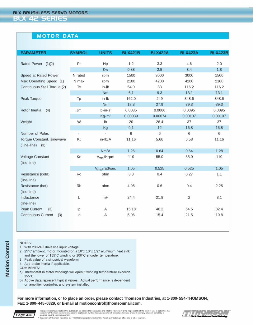
Page 436
BLX BRUSHLESS SERVO MOTORS
BLX 42 SERIES
For more information, or to place an order, please contact Thomson Industries, at 1-800-554-THOMSON, Fax: 1-800-445-0329, or E-mail at [email protected].
The specifications and data in this publication are believed to be accurate and reliable. However, it is the responsibility of the product user to determine thesuitability of Thomson products for a specific application. While defective products will be replaced without charge if promptly returned, no liability isassumed beyond such replacement.
* Trademark of Thomson Industries, Inc. THOMSON is registered in the U.S. Patent and Trademark Office and in other countries.
Mo
tio
n C
ont
rol
MOTOR DATA
PARAMETER SYMBOL UNITS BLX421B BLX422A BLX423A BLX423B
Rated Power (1)(2) Pr Hp 1.2 3.3 4.6 2.0
Kw 0.88 2.5 3.4 1.8
Speed at Rated Power N rated rpm 1500 3000 3000 1500
Max Operating Speed (1) N max rpm 2100 4200 4200 2100
Continuous Stall Torque (2) Tc in-lb 54.0 83 116.2 116.2
Nm 6.1 9.3 13.1 13.1
Peak Torque Tp in-lb 162.0 249 348.6 348.6
Nm 18.3 27.9 39.3 39.3
Rotor Inertia (4) Jm lb-in-s2 0.0035 0.0066 0.0095 0.0095
Kg-m2 0.00039 0.00074 0.00107 0.00107
Weight W lb 20 26.4 37 37
Kg 9.1 12 16.8 16.8
Number of Poles - - 6 6 6 6
Torque Constant, sinewave Kt in-lb/A 11.16 5.66 5.58 11.16
( line-line) (3)
Nm/A 1.26 0.64 0.64 1.28
Voltage Constant Ke Vrms /Krpm 110 55.0 55.0 110
(line-line)
Vrms /rad/sec 1.05 0.525 0.525 1.05
Resistance (cold) Rc ohm 3.3 0.4 0.27 1.1
(line-line)
Resistance (hot) Rh ohm 4.95 0.6 0.4 2.25
(line-line)
Inductance L mH 24.4 21.8 2 8.1
(line-line)
Peak Current (3) Ip A 15.18 46.2 64.5 32.4
Continuous Current (3) Ic A 5.06 15.4 21.5 10.8
NOTES:1. With 230VAC drive line input voltage.2. 25°C ambient, motor mounted on a 10"x 10"x 1/2" aluminum heat sink
and the lower of 155°C winding or 100°C encoder temperature.3. Peak value of a sinusoidal waveform.4. Add brake inertia if applicable.COMMENTS:a) Thermostat in stator windings will open if winding temperature exceeds
155°C.b) Above data represent typical values. Actual performance is dependent
on amplifier, controller, and system installed.

Page 437
For more information, or to place an order, please contact Thomson Industries, at 1-800-554-THOMSON, Fax: 1-800-445-0329, or E-mail at [email protected].
BLX BRUSHLESS SERVO MOTORS
BLX 42 SERIES
The specifications and data in this publication are believed to be accurate and reliable. However, it is the responsibility of the product user to determine thesuitability of Thomson products for a specific application. While defective products will be replaced without charge if promptly returned, no liability isassumed beyond such replacement. Viton® is a registered trademark of E. I. DuPont de Nemours & Company.
* Trademark of Thomson Industries, Inc. THOMSON is registered in the U.S. Patent and Trademark Office and in other countries.
Mo
tion C
ontro
l
MODEL L1† L2† A
BLX421 218.2 183.7 19.0[8.59] [7.209] [0.748]
BLX422 281.7 246.4 24.00[11.09] [9.70] [0.9449]
BLX423 345.2 308.9 24.00[13.59] [12.20] [0.9449]
†Add 2.0" for brake option
DIODEIN4007
Encoder/Therm Connector PT02E-16-23PPin Function
T ENC GROUND
E ENC +5VDC
F ENC CH A
U ENC CH A\
G ENC CH B
V ENC CH B\
H ENC CH Z
W ENC CH Z\
J HALL CH U
K HALL CH U\
X HALL CH V
Pin Function
L HALL CH V\
Y HALL CH W
M HALL CH W\
N GND/CABLE SHIELD
S THERM
R THERM
D GND
A NO CONNECTION
B NO CONNECTION
C NO CONNECTION
P NO CONNECTION
Z NO CONNECTION
Motor/Brake Connector PT02E-16-8PPin Function
A MOTOR PHASE R
B MOTOR PHASE S
C MOTOR PHASE T
D PE GND
E BRAKE SHLD
F BRAKE (+)
G BRAKE (-)
H NO CONNECTION
NOTE:1-Dimensions are in millimeters.
Inch dimensions are shown inbrackets.
2-Max Axial Load: 25 lb3-Max Radial Load: 40 lb4-Motor Finish: Black Epoxy5-Motor Sealed to IP656-Front Shaft Seal Installed,
Type: Viton®

Page 438
BLX BRUSHLESS SERVO MOTORS
BLX 60 SERIES
For more information, or to place an order, please contact Thomson Industries, at 1-800-554-THOMSON, Fax: 1-800-445-0329, or E-mail at [email protected].
The specifications and data in this publication are believed to be accurate and reliable. However, it is the responsibility of the product user to determine thesuitability of Thomson products for a specific application. While defective products will be replaced without charge if promptly returned, no liability isassumed beyond such replacement.
* Trademark of Thomson Industries, Inc. THOMSON is registered in the U.S. Patent and Trademark Office and in other countries.
Mo
tio
n C
ont
rol NOTES:
1. With 230VAC drive line input voltage.2. 25°C ambient, motor mounted on a 12" x 12" x 1/2" aluminum heat sink
and the lower of 155°C winding or 100°C encoder temperature.3. Peak value of a sinusoidal waveform.4. Add brake inertia if applicable.COMMENTS:a) Thermostat in stator windings will open if winding temperature exceeds
155°C.b) Above data represent typical values. Actual performance is dependent
on amplifier, controller, and system installed.
MOTOR DATA
PARAMETER SYMBOL UNITS BLX602B BLX603A
Rated Power (1)(2) Pr Hp 4.5 9.1
Kw 3.4 6.8
Speed at Rated Power N rated rpm 1500 2400
Max Operating Speed (1) N max rpm 1750 2700
Continuous Stall Torque (2) Tc in-lb 210 280
Nm 23.7 31.5
Peak Torque Tp in-lb 630 840
Nm 70.8 94.4
Rotor Inertia (4) Jm lb-in-s2 0.0016 0.0276
Kg-m2 0.00212 0.00307
Weight W lb 51 64
Kg 23.1 29
Number of Poles - - 6 6
Torque Constant, sinewave Kt in-lb/A 12.0 7.11
(line-line) (3)
Nm/A 1.35 0.8
Voltage Constant Ke Vrms /Krpm 1.1 0.669
(line-line)
Vrms /rad/sec 0.72 0.13
Resistance (cold) Rc ohm 1.08 0.2
(line-line)
Resistance (hot) Rh ohm 12.6 4.65
(line-line)
Inductance L mH 6.1 1.4
(line-line)
Peak Current (3) Ip A 54.5 122
Continuous Current (3) Ic A 18.2 40.7
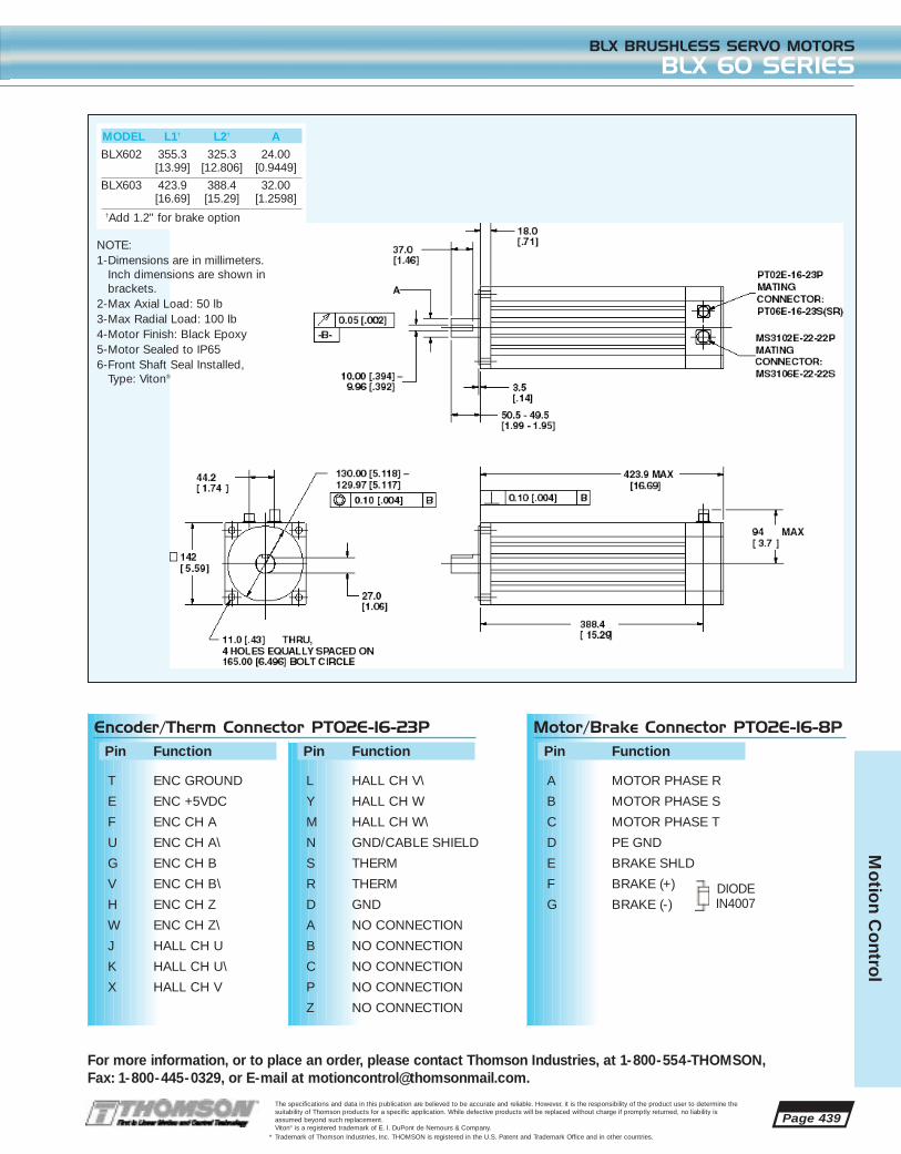
Page 439
For more information, or to place an order, please contact Thomson Industries, at 1-800-554-THOMSON, Fax: 1-800-445-0329, or E-mail at [email protected].
BLX BRUSHLESS SERVO MOTORS
BLX 60 SERIES
The specifications and data in this publication are believed to be accurate and reliable. However, it is the responsibility of the product user to determine thesuitability of Thomson products for a specific application. While defective products will be replaced without charge if promptly returned, no liability isassumed beyond such replacement. Viton® is a registered trademark of E. I. DuPont de Nemours & Company.
* Trademark of Thomson Industries, Inc. THOMSON is registered in the U.S. Patent and Trademark Office and in other countries.
Mo
tion C
ontro
l
MODEL L1† L2† A
BLX602 355.3 325.3 24.00[13.99] [12.806] [0.9449]
BLX603 423.9 388.4 32.00[16.69] [15.29] [1.2598]
†Add 1.2" for brake option
DIODEIN4007
Encoder/Therm Connector PT02E-16-23PPin Function
T ENC GROUND
E ENC +5VDC
F ENC CH A
U ENC CH A\
G ENC CH B
V ENC CH B\
H ENC CH Z
W ENC CH Z\
J HALL CH U
K HALL CH U\
X HALL CH V
Pin Function
L HALL CH V\
Y HALL CH W
M HALL CH W\
N GND/CABLE SHIELD
S THERM
R THERM
D GND
A NO CONNECTION
B NO CONNECTION
C NO CONNECTION
P NO CONNECTION
Z NO CONNECTION
Motor/Brake Connector PT02E-16-8PPin Function
A MOTOR PHASE R
B MOTOR PHASE S
C MOTOR PHASE T
D PE GND
E BRAKE SHLD
F BRAKE (+)
G BRAKE (-)
NOTE:1-Dimensions are in millimeters.
Inch dimensions are shown inbrackets.
2-Max Axial Load: 50 lb3-Max Radial Load: 100 lb4-Motor Finish: Black Epoxy5-Motor Sealed to IP656-Front Shaft Seal Installed,
Type: Viton®

Page 440
BLX BRUSHLESS SERVO MOTORS
COMMON SPECS
For more information, or to place an order, please contact Thomson Industries, at 1-800-554-THOMSON, Fax: 1-800-445-0329, or E-mail at [email protected].
The specifications and data in this publication are believed to be accurate and reliable. However, it is the responsibility of the product user to determine thesuitability of Thomson products for a specific application. While defective products will be replaced without charge if promptly returned, no liability isassumed beyond such replacement.
* Trademark of Thomson Industries, Inc. THOMSON is registered in the U.S. Patent and Trademark Office and in other countries.
Mo
tio
n C
ont
rol
ENCODER NOTES
1. Resolution = 2000 lines/rev. (8000 counts)
2. Power Supply = 5VDC±5%, 200mA max.
3. Output circuit is 26LS31 differential line driver,20mA max sink/source
4. Commutation sensors in encoder have differentialoutputs.
Note: All motor and sensor timing for CW rotation as viewed from shaft end

The specifications and data in this publication are believed to be accurate and reliable. However, it is the responsibility of the product user to determine thesuitability of Thomson products for a specific application. While defective products will be replaced without charge if promptly returned, no liability isassumed beyond such replacement.
* Trademark of Thomson Industries, Inc. THOMSON is registered in the U.S. Patent and Trademark Office and in other countries.
Mo
tion C
ontro
l
Page 441
For more information, or to place an order, please contact Thomson Industries, at 1-800-554-THOMSON, Fax: 1-800-445-0329, or E-mail at [email protected].
MOTION CONTROL SOLUTION GUIDE
APPLICATION EXAMPLE
Rolling Dies
DRVINFO
Application Description
Flat stock clamped to a positioning stage is drawn through two rolling dies which form the material into a profile. At the end of a pre-determined stroke length, the clamp releases, the slideretracts, and the material is cut off. The material is once again clamped and the action repeats.The actual cutoff and clamping mechanisms are located on a Thomson belt driven linear motionslide which is energized by outputs from the drives. The length of the material must be alteredas required for the job.
Requirements
• One axis stand alone capability• Configurable I/O• On the floor programmability
The Solution
(1) APi-421B-DM020-L15 AXI-PAK* digital servo drive package with indexing(1) TP-001 Touchpad
A Thomson Industries AXI-PAK drive/motor combination with indexing capability and touch padhas been selected to satisfy this application. The drive’s programmable outputs are configuredto fire when moves are complete thus initiating the clamp and cut operations. The touch pad allows the move lengths, speeds, accelerations, etc. to be set on the factory floor without a separate computer. The drive is homed automatically upon power up.
Application: Draw and cut to length

Page 442
Mo
tio
n C
ont
rol
MOTION CONTROL SOLUTION GUIDE
APPLICATION EXAMPLE
For more information, or to place an order, please contact Thomson Industries, at 1-800-554-THOMSON, Fax: 1-800-445-0329, or E-mail at [email protected].
The specifications and data in this publication are believed to be accurate and reliable. However, it is the responsibility of the product user to determine thesuitability of Thomson products for a specific application. While defective products will be replaced without charge if promptly returned, no liability isassumed beyond such replacement.
* Trademark of Thomson Industries, Inc. THOMSON is registered in the U.S. Patent and Trademark Office and in other countries.
Application Description
Sheet stock, which has been clamped in place on an X-Y table, will be guided under the headof a focusing beam laser. As these pre-programmed patterns are being traced, any height deviations of the sheet metal with respect to the laser head will jeopardize the integrity and accuracy of the cut. This condition will be compensated for by a sensor attached to the laserhead mounted on the Z axis.
Requirements
• Three axis control, smooth motion, high accuracy• Stand alone operation• Linear and circular Interpolation, and contouring• Analog inputs• Multi-tasking capabilities• User defined I/O
The Solution
(1) TMC-2004-CO multi-axis motion controller(2) AP-342A-DM020-L15 AXI-PAK* servo axis packages for X and Y(1) AP-232A-DM005-L15 AXI-PAK servo axis packages for Z
Thomson Industries TMC-2004-CO multi-tasking controller has been selected to control threeAXI-PAK servo axis packages. The controller provides coordinated motion between the X andY axes while, at the same time closing a position loop around the Z axis and the analog input towhich the height sensor is connected. The cut progresses smoothly and accurately as the controller processes these two programs simultaneously, while having the additional capabilityto run two more programs, for a total capacity of four. These two additional programs can beused to monitor laser beam quality and/or safety devices located on the machine.

Mo
tion C
ontro
l
Page 443
For more information, or to place an order, please contact Thomson Industries, at 1-800-554-THOMSON, Fax: 1-800-445-0329, or E-mail at [email protected].
MOTION CONTROL SOLUTION GUIDE
APPLICATION EXAMPLE
The specifications and data in this publication are believed to be accurate and reliable. However, it is the responsibility of the product user to determine thesuitability of Thomson products for a specific application. While defective products will be replaced without charge if promptly returned, no liability isassumed beyond such replacement.
* Trademark of Thomson Industries, Inc. THOMSON is registered in the U.S. Patent and Trademark Office and in other countries.
Application Description
Automate a material transfer process by integrating assembly workstations and the necessarylinear and rotary motion stages into one machine. All motion is to be coordinated with an existing PLC. Finished assemblies will be sensed and picked on a first in first out basis andtransferred to an offload conveyor which will index as necessary. Product is then forwarded to apackaging station.
Requirements
• Smooth, quick motion• High reliability• High-speed indexing for increased throughput• Interface with a PLC• Accurate position control• Non-volatile memory for move profiles
The Solution
(3) APi-234A-DM010-L15 AXI-PAK* digital servo drive packages with indexing
Three Thomson Industries AXI-PAK digital servo drive packages have been selected. Each willuse its indexing capability to execute up to 8 preset move profiles while communicating with the PLC through user defined I/O. Finished assemblies are placed in “out” boxes by their respective assemblers and sensed by the PLC. A Thomson linear motion belt driven slide, controlled by an AXI-PAK, will be directed to the out box. The rotary stage indexes as requiredand pneumatics make the pick. Product is then transferred to the offload conveyor, which indexes ahead as necessary. The process repeats itself, with the PLC sequencing a total of 24move profiles provided by the Thomson drives.
Application: Offload transfer line

The specifications and data in this publication are believed to be accurate and reliable. However, it is the responsibility of the product user to determine thesuitability of Thomson products for a specific application. While defective products will be replaced without charge if promptly returned, no liability isassumed beyond such replacement.
* Trademark of Thomson Industries, Inc. THOMSON is registered in the U.S. Patent and Trademark Office and in other countries.
Servo Sizing SoftwareSelecting the right servo solution has never
been easier or more accurate. Thomson
servo sizing software gives you the exact part
number(s) for the solution to your motion
control application. Ballscrew (leadscrew), belt
drive, and direct drive configurations are
supported. If using a Thomson linear motion
system, simply choose the part number from
a list box and all system parameters are auto-
matically entered. You can also design your
own system with Thomson components or
your own. Then, specify your move profile
and the suitable AXI-PAK* engineered servo
axis packages are listed.
If using a Thomson system, simply enter its part number tohave all system parameters automatically entered. Youmay also design your own system using Thomson components or your own/generic components. Screw,belt, and direct driven systems are supported.
Actual AXI-PAK servo axis package part numbers are generated for a matched motor-drive-cable solution. Allavailable solutions are listed with the suitable packageshighlighted. Torque margins are displayed for convenience.
Your move profile is easily entered in a graphical way.Simply drag the profile as desired and all values are updated. Triangular, trapezoidal, or complex multi-speed/acceleration/deceleration moves are supported.
In addition to the program’s rich graphical output bothon screen and printed, tabulated values are available forall design parameters, move profile, torque require-ments, and chosen motion control components.
Call 1-800-55-4-THOMSON for your FREE copy of Thomson
servo sizing software
FREE
Page 444For Application Engineering assistance contact the Thomson Technical HelpLine at 1-800-554-8466.
* Trademark of Thomson Industries, Inc. THOMSON is registered in the U.S. Patent and Trademark Office and in other countries.
Mo
tio
n C
ont
rol

Page 445
Free from theThomson Technology Library
*Trademark of Thomson Industries, Inc. THOMSON is registered in the U.S. Patent and Trademark Office and in other countries.
It’s as easy as checking a box. Make sure your Thomson Engineering Library is up to date.

Page 446
Thomson Micron*
Complete engineering data and selection guide forTrue Planetary* gearheads and position feedbacktransducers.Literature No. 10-00-000-6001
TRUE PLANETARY GEARHEAD SELECTION GUIDEAND ENGINEERING CATALOG
Linear Bearings & Components (Inch)
144-page guide includes specifications of all linearBall Bushing* bearings, pillow blocks and supportrails. Also featured are the new Super Smart BallBushing* bearings, Super Ball Bushing* bearings andRoundWay* linear roller bearings.Literature No. 01-00-000-6001-03
ADVANCED LINEAR MOTION TECHNOLOGY GUIDE
Linear Bearings & Components (Metric)
A 66-page comprehensive catalog provides information and specifications on advanced linearmotion metric products. These include Super SmartBall Bushing bearings, Smart MultiTrac BallBushing* bearings and Smart Rail* linear guides.Literature No. 01-50-000-6001-02
ADVANCED LINEAR MOTION METRIC PRODUCTS
Thomson Saginaw
This 92-page technology guide is a complete sourceof information on high performance ThomsonSaginaw* ball screws, including rolled thread assemblies, precision ground assemblies and ballsplines. Also included are product descriptions,applications, specifications, design and selection criteria and mounting instructions.Literature No. 06-00-000-6001-02
ADVANCED LINEAR ACTUATOR GUIDE
Thomson 60 Case
60-page catalog describing the features, benefits andtechnical specifications of the complete line of 60Case* LinearRace* shafting. Engineering templatesare provided for ease of ordering.Literature No. 02-00-000-6001
THOMSON 60 CASE LINEARRACE SHAFTING CATALOG
Thomson Airpax Mechatronics
Features the largest and most powerful capabilityper size in the industry and:•Ideal for valve actuators, fluid displacement
pumps, copiers, printers, fax machines, paper feeddevices, character positioning devices, climate con-trol, and fluid flow-rate management
•Customization to meet your precise design needs•Fast, powerful, precise positioning•Large selection of permanent magnet stepper
motors – from 15mm to 60mm•Pioneer in digital linear actuator (DLA) technologyLiterature No. 12-00-000-6001
PRODUCT SELECTION AND ENGINEERING GUIDE
Thomson Saginaw
Brochure describes ball screw repair services fromThomson Saginaw that can save a customer up to90% of the cost of a new ball screw. Topics includerepair capabilities, inspection procedures, and special programs such as emergency repairs, train-ing seminars, and preventive maintenance. Brochurealso includes information on how a ball screw operates and what causes damage and wear.Literature No. 06-16-000-6400-01
EXPERT BALL SCREW RECONDITIONING FOR ANY DESIGN OR MAKE
Thomson Micron
Gearhead Express* ships True Planetary* gearheadswithin 24 hours–the fastest delivery of planetarygearheads available from any industry source. Theprogram offers two precision classes; high precisionDuraTrue* gearheads and Ultra precision UltraTrue*gearheads. Both gearhead product groups mountwith the error-free Redimount* motor mounting system.Literature No. 10-08-000-6001
GEARHEAD EXPRESS
Thomson Saginaw
This 28-page catalog describes the ThomsonSaginaw* Performance Pak, PPA*, actuators andaccessories for commercial, institutional and industrial linear actuation. PPA’s combine the efficiency of a ball screw with an electric motor for a ready-to-install positioning system. Includescomplete engineering and selection data and application examples. Literature No. 09-00-000-6001-01
PERFORMANCE PAK ACTUATORS–ENGINEERING AND SELECTION GUIDE
1-888-55-4-MOTION
TRUE PLANETARY™ GEARHEADS
HIGH PRECISION • LOW BACKLASH • EASY TO MOUNT
™
*Trademark of Thomson Industries, Inc. THOMSON is registered in the U.S. Patent and Trademark Office and in other countries.
Linear Motion Solutions
450-page guide permits quick selection of standardoff-the-shelf linear motion systems and accessories.Easy to use, it presents inch and metric systems sep-arately and has special sections on motion control, accessories and engineering support. Using thegraphs, formulas and illustrations included through-out, complete systems can be designed, specifiedand ordered with a single part number. Literature No. 99-40-000-6100
LINEAR GUIDES, SYSTEMS, SLIDES & STAGES, AND MOTION CONTROL SOLUTION GUIDE

Page 447
Corporate
When buying linear motion products you want toget the very best. This brochure explains why youshould specify Thomson products. Thomson products offer the highest loads, longest life, and the most advanced features and benefits available in the world. Thomson offers 10,000 standard off-the-shelf linear motion products. Literature No. 99-00-000-6416-01
WHY YOU SHOULD SPECIFY THOMSON LINEAR MOTION PRODUCTS
Corporate
A simple one-page brochure that explains how to use the LinearFax* technical data system. Lists the product information available through this service. Literature No. 99-00-000-6401
INFORMATION BY FAX!
Systems
This brochure presents an overview ofThomson linear motion systems, both pre-engineered, off-the-shelf designs andcurrently engineered custom designs forproprietary equipment. Typical applica-tions in the semiconductor industryinclude wafer processing and inspection,wafer furnaces, robotic wafer arms, trans-port and flat panel display processing. Literature No. 03-00-000-6402
LINEAR MOTION SYSTEMS FORSEMICONDUCTOR PROCESSING
Systems
This brochure shows 1-to 4-axis modularservo systems complete with motors andcontrols. These systems reduce productdevelopment time and time-to-market fornew packaging equipment with such appli-cations as width adjustment, stretch wrap-ping and fluid dispensing. The componentsof these systems are stocked for quickassembly, matching of motors and controls,shipment and ease of in-plant operation. Literature No. 03-00-000-6403
THOMSON LINEAR MOTION SYSTEMS FOR PACKAGING MACHINERY
THOMSON INDUSTRIES, INC.2 Channel Drive • Port Washington, NY 11050 USA
(1 (800) 554-8466 • Fax: 1 (800) 445-0329E-mail: [email protected]
Download literature from
www.thomsonindustries.com orliterature by fax:
LinearFax* 1-800-554-THOMSON *Trademark of Thomson Industries, Inc. THOMSON is registered in the U.S. Patent and Trademark Office and in other countries.
Corporate
An eight-page brochure featuring a listing ofThomson’s linear motion products. Included arebrief descriptions of each product line.Literature No. 99-00-000-6430
THE WORLD’S MOST COMPLETE LINEAR MOTION & CONTROL LINE
Molded Products
20-page design guide for Nyliner engineered polymer bearings includes easy-to-use technical andselection data, specification and application guide-lines. Special section included on Nyliner Plus* bearings. They are composed of advanced thermo-plastics for increased PV ratings and operation athigher temperature and lower friction.Literature No. 04-00-000-6001-03
NYLINER BEARING DESIGNER’S GUIDE
Thomson Precision Ball
A 22-page catalog covers standard and custom precision balls, guaranteed to meet ABMAstandards. Available in chrome and stainless steeland many special materials-and in 0.005” to 1”diameters, in grades 3-1000. The catalog also features a full-line of balls in ferrous, non-ferrousand ceramic materials: from 0.0525 in.; and inGrades 10-1000. Literature No. 07-00-000-6001-02
THOMSON PRECISION BALL CATALOG

FAX ALL REQUESTS TO 516-944-1045 (in UK 0800 9751001)To request, simply check the box next to the literature listing and enter the quantity desired.
All requests filled within 72 hours after receipt of form.
LINEAR MOTION SYSTEMS QTYLinear Motion & Control Solutions CatalogCT Literature No. 99-40-000-6100Advanced Linear Motion Systems Product OverviewCT Literature No. 03-00-000-6005-03Thomson Linear Motion Systems for Semiconductor ProcessingCT Literature No. 03-00-000-6402Thomson Linear Motion Systems for Packaging MachineryCT Literature No. 03-00-000-6403MicroStage* SystemsTB Literature No. 03-55-000-6001Motion Control Solutions CatalogCT Literature No. 03-14-000-6001Linear Motion System Catalog on CD ROMincluding 2D DFX CAD Files and Linear Selector* SoftwareCD Literature No. 03-00-000-6005
LINEAR BEARINGS QTYAdvanced Linear Motion Technology GuideCT Literature No. 01-00-000-6001-03Advanced Linear Motion Metric ProductsCT Literature No. 01-50-000-6001-02UltraProof* Ball Bushing* bearingTB Literature No. 01-01-100-6501Smart MultiTrac Ball Bushing* blockTB Literature No. 01-58-300-6501Super Smart Ball Bushing* bearing Rigid Pillow BlockTB Literature No. 01-01-200-6501Miniature Instrument Ball Bushing bearingsand Matched SetsTB Literature No. 01-03-104-6001Metric Miniature Ball Bushing* bearingsTB Literature No. 01-03-104-6500-01Super Smart Ball Bushing* bearings (JIS)TB Literature No. 01-81-100-6001-03Super Smart Ball Bushing* bearings(6-Track) Inch & ISOTB Literature No. 01-01-400-6001Linear Motion Products Price BookPL Literature No. 01-00-000-6901Thomson Linear Motion Products MetricInterchange GuideMS Literature No. 01-50-000-6003
60 CASE LINEARRACE shafting QTYGenuine 60 Case* LinearRace* shaftingCT Literature No. 02-00-000-6001Thomsalloy* 60 Case LinearRace shafting TB Literature No. 02-02-006-600260 Case Flanged Shaft Support BlocksTB Literature No.02-03-103-6001-0160 Case LinearRace JIT shaftingTB Literature No.02-02-005-6001-01Linear Motion Products Price BookPL Literature No.01-00-000-690160 Case shafting Poster (Rolled in Tube)MS Literature No. 02-02-000-640260 Case shafting Poster (Folded)MS Literature No. 02-02-000-640260 Case shafting & Super Smart Ball Bushing* bearing Poster MS Literature No. 99-00-000-6424
LINEAR GUIDES QTYLinear Motion & Control Solutions CatalogCT Literature No. 99-40-000-6100Maintenance-Free Linear GuidesTB Literature No. 14-00-000-6800AccuGlide* Miniature R-Series Linear Guides TB Literature No. 14-03-100-6001AccuGlide Protective BellowsTB Literature No. 05-02-100-6001AccuGlide Scraper OptionTB Literature No. 14-50-100-6001Linear Guides Price BookPL Literature No. 14-00-000-6901Linear Guides Interchange Guide(THK/STAR to Thomson)MS Literature No. 05-02-000-6014Choosing Linear Guides for Smooth Moves(MD Article 5/98)MS Literature No. 14-00-000-6200Linear Guide CAD (.dxf) filesCD Literature No. 14-00-000-6301AccuMax* Linear Guide VideoVO Literature No. 05-03-000-6800
SAGINAW* BALL SCREWS QTYAdvanced Linear Actuator GuideCT Literature No. 06-00-000-6001-02Expert Ball Screw Reconditioning for any Design or Make CT Literature No. 06-16-000-6400-01Performance Pak* Actuators/Engineering and Selection Guide CT Literature No. 09-00-000-6001-01Ball Screw Alignment Procedures CT Literature No. 06-00-000-6403High Capacity Miniature Ball Screws TB Literature No. 06-01-005-6001-02Ball Screw Inspection KitTB Literature No. 06-16-000-6001Quick Mount* V-Series Bearing Support BlocksTB Literature No: 06-21-100-6001Thomson T/K Modified Acme AssembliesLiterature No. 06-30-000-6001-01Telescoping Ball Screws TB Literature No. 06-35-000-6001Precision Gear Drive Units TB Literature No. 06-36-000-6001Class 5 Metric Precision Ball Screw AssemblyTB Literature No. 06-51-000-6001-01Class 3 Metric Precision Ball Screw AssemblyTB Literature No. 06-52-000-6001High-Speed HPD In-Line Ball Screw ActuatorTB Literature No. 09-11-100-6001
Ball Screw and PPA Price ListPL Literature No. 06-00-000-6900-1Actuators for All-Weather Antenna PositioningMS Literature No. 09-10-000-6400
MOLDED PRODUCTS QTYNyliner* Bearing Designer’s GuideCT Literature No. 04-00-000-6001-03Nyliner Plus* Bearing Test & Evaluation KitTB Literature No. 04-01-100-6001-02 Nyliner Bushing Bearings TB Literature No. 04-02-000-6501Repair Tool KitMS Literature No 04-02-100-6001FluoroNyliner* Bushing Bearings TB Literature No. 04-03-000-6001-3Zero Clearance BearingsTB Literature No. 04-04-000-6001Nyliner, Nylined*, & Nyliner Plus EngineeredPolymer Bearings - Complete Price Guide PL Literature No. 04-00-000-6902Nyliner Bushing Bearings/FluoroNyliner Bushing Bearings - Complete Price GuidePL Literature No. 04-00-000-6903FluoroNyliner Bushing Bearings CompleteInterchange ListPL Literature No. 04-03-000-6003
MICRON* TRUE PLANETARY* GEARHEADS QTYMicron Consolidated CatalogCT Literature No. 10-00-000-6001Gearhead Express BrochureCT Literature No. 10-008-000-6001Programmable Limit Switches TB Literature No. 10-05-000-6001
THOMSON AIRPAX MECHATRONICS QTYAirpax Consolidated CatalogTB Literature No. 12-00-000-6001
THOMSON PRECISION BALL QTYThomson Precision Ball CatalogCT Literature No. 07-00-000-6001-02
CORPORATE CATALOGS & BROCHURES QTYWhy You Should Specify Thomson Linear Motion ProductsCT Literature No. 199-00-000-6416-01LinearFax* Technical DataTB Literature No. 99-00-000-6401The World's Most Complete Linear Bearing LineTB Literature No. 99-00-000-6430Thomson 2000VO Literature No. 99-00-000-6301
IBL BALL SCREWS QTYCT LITERATURE NO. 08-00-000-6002
Code: CT-Catalog/Brochure; TB-Technical Bulletin; PL-Price List; CD-CD ROM; MS-Miscellaneous; VO-Video
COMPANY NAME
NAME
ADDRESS
CITY STATE ZIP
COUNTRY
PHONE FAX E-MAIL
*Trademark of Thomson Industries, Inc. THOMSON is registered in the U.S. Patent and Trademark Office and in other countries. Page 448

ENGINEERING CONVERSION FACTORS
For Application Engineering assistance contact the Thomson Technical HelpLine at 1-800-554-8466.* Trademark of Thomson Industries, Inc. THOMSON is registered in the U.S. Patent and Trademark Office and in other countries. Page 449
ACCELERA-TION
Feet persecondsquared
ft./s2
Meters persecondsquared
m/s2
Metres persecondsquared
m/s2
POWERFoot pound per
minutelbf-ft./min.
Force per secondkgf-m/s
Newton Metreper
secondNm/s
VELOCITYFeet persecond
ft./s
Meters persecond
m/s
Meters persecond
m/s
TORQUEor
WORK
Inch Poundslbf-in.
KilogramMeterskgf-m
Newton-Metres
Nm
STRESSor
PRESSURE
Pounds persquare inch
lbf/in.2
Kilograms persquare meter
kgf/m2
PascalPa
FORCEPound Force
lbf
Kilogram Forcekgf
NewtonN
MASSPound
lbmKilogram
kgKilogram
kg
AREASquare Inch
in.2
Square Meterm2
Square Metrem2
LENGTHInchin.
Meterm
Metrem
Metrem
1 in. = 25.4 mm1 mm = 0.03937 in.1 m = 3.2808 ft.1 ft. = 0.3048 m
1 in.2 = 6.4516 cm2
1 cm2 = 0.155 in.2
1 m2 = 10.764 ft2
1 ft.2 = 0.092903 m2
1 lbm = 0.45359237 kg
1 kg = 2.2046 lb
1 lbf = 0.45359237 kgf1 lbf = 4.44822 N1 kgf = 2.2046lbf1 kgf = 9.80665 N1 N = 0.1019716 kgf1 N = 0.224809 lbf
1 MPa = 106 N/m2 = N/mm2
1 kPa = 103 N/m2
1 lbf/inch2 = 0.070307 kgf/cm2
1 lbf/inch2 = 7.0307 x 10⁻⁴ kgf/mm2
1 lbf/inch2 = 6.8947 x 10⁻³ N/mm2 (MPa)1 kgf/cm2 = 14.2233 lbf/in.2
1 kgf/cm2 = 9.80665 x 10⁻² N/mm2 (MPa)
1 lbf-in. = 1.1521 kgf-cm1 kgf-cm = 0.8679 lbf-in.1 lbf-in. = 0.1129848 Nm1 kgf-m = 9.80665 Nm1 kgf-cm = 9.80665 x 10⁻² Nm1 Nm = 8.85 lbf-in.1 Nm = 10.19716 kgf-cm
1 kW = 1000Nm/s1 kW = 60,000 Nm/s1 kW = 44,220 lbf-ft./min.1 kW = 1.341 hp1 hp = 75 kgf-m/s1 hp = 44,741 Nm/min.1 hp = 33,000 lbf-ft.min.1 hp = 0.7457 kW
1 ft./sec. = 0.3048 m/s1 in./sec. = 2.54 cm/s1 ft./sec. = 0.00508 m/s1 mile/hr. = 0.44704 m/s1 km/hr. = 0.27777 m/s1 mile/hr = 1.609344 km/hr.
1 ft./s2 = 0.3048 m/s2
QUANTITYCONVENTIONAL
Inch Unit Metric Unit (MKS)SI UNIT CONVERSION FACTORS

ITT Industries
Two-time winnerGold Award
1800 DISTRIBUTORS WORLD WIDE!In North America: 1-800-554-THOMSON
Europe: (44) 1271 334 500Elsewhere: 516-883-8000
ONE SOURCE FOR ALL LINEAR MOTION AND CONTROL APPLICATIONS
2 Channel DrivePort Washington, NY 11050 USA
All Thomson Industries Manufacturing Locations areISO 9000 Certified and Automotive Facilities
Operate to QS-9000 StandardsThree-time winner General Motors Supplier of the Year
ISO 9000
Trademark of Thomson Industries, Inc. THOMSON is registered in the U.S. Patent and Trademark Office and in other countries. The specifications in this publication are believed to be accurateand reliable. However, it is the responsibility of the product user to determine the suitability of Thomson products for a specific application. While defective products will be replaced without chargeif promptly returned, no liability is assumed beyond such replacement. ©1999 Thomson Industries, Inc. Printed in the U.S.A. RIPON 250K HAP/CP 12-14-99 9808-16.qxd 99-40-000-6100
*
FOR IMMEDIATE ASSISTANCE:
USA, Canada Free =: 1 (800) 554-8466or Mexico: Free Fax: 1 (800) 445-0329
Internet: www.thomsonindustries.comE-mail: [email protected]: [email protected]*: 1 (800) 55-4-THOMSON
Europe: =: (44) 1271 334 500Sales Fax: (44) 1271 334 502
UK Free =: 0800 9751000Free Fax: 0800 9751001
France Free =: 0800 90 5721Free Fax: 0800 91 6315
Germany Free =: 0130 816 553Free Fax: 0130 816 552
Elsewhere: =: 1 (516) 883-8937Fax: 1 (516) 883-7109
or write:Thomson Industries, Inc.2 Channel Drive Port Washington, NY 11050 USA
PRESORTED STANDARD
U.S. POSTAGE PAIDTHOMSON
INDUSTRIES, INC.
Worldwide Manufacturing, Service & SalesUSA • HEADQUARTERS: Port Washington, NY
• Farmingdale, NY • Ronkonkoma, NY • Lancaster, PA • Bristol, CT • Unionville, CT • Cheshire, CT • Saginaw, MI • Bay City, MI
Mexico • Tijuana
United Kingdom • Barnstaple • Farnborough
Malaysia • Kluang
Singapore
G M
S U P P L I E R
OF THE
Y E A R
www.thomsonindustries.com