linear motion slides - componentsstock.comcomponentsstock.com/shop/pdf/optima.pdf · thickness:-15...
TRANSCRIPT
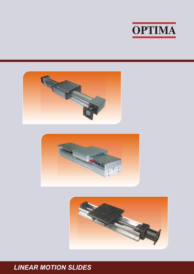
LINEAR MOTION SLIDES

INTRODUCTION
CONTENTS
Efficiency in automation can only be attained with simplified
processes and systems. To achieve this task, aluminum profile
systems and modules suitable for automated applications are
available. The simplicity of aluminum profile systems and integrated
components ensures functionality and reliability. All the components
individually and in sets, are designed and constructed in such a way
that they can be assembled without any problem and therefore
provide an economical solution.
These systems find excellent solutions for a wide range of
automation applications, including packaging equipment, pick and
place units, guard door slides, plasma cutting, painting, dispensing,
welding, cut off machine and many other industrial machines.
Standard sizes and configuration are available at short notice, but
custom solutions can be designed, engineered and manufactured to
meet specific requirements.
Description Page 1 LFR Modules 1 - 13
1 LM Slide Units 14 -18
1 Positioner Pipe Slide 19
1 Cross Roller Guides 20 - 23
1 Frictionless Slides 24 - 25
1 Dust Proof Slide 26 - 27
1 M + V Guides 28
1 Spindle Unit 29
1 Chamfering Machine 30
1 Application Examples 31

LFR MODULES
1
LINEAR MODULES WITH DRIVE SYSTEMS
Linear guidance system is manufactured using Aluminum extrusions, Precision linear shafts, LFR Track Rollers. The aluminum-extruded profile is stabilized and anodized. Aluminum extrusion forms the main support element, and the hardened steel rods inserted in the raceway forms the guiding surface. Guide rods are induction hardened, ground and hard chrome plated. The complete system is strong, lightweight and compact design. The combined features of the two materials and the relevant working technologies enable the system to be used in many applications as carrying structures.
The features include track rollers life lubrication and continuous lubricated on shafts through oil, felt at both ends of carriage plate.
Linear accuracy can be achieved within 0.100mm and most of the systems have no stroke limitations, maximum stroke up to 50mts in length have been executed so far. These sliding systems can be driven by ball screw, timing belts, rack & pinion, lead screw, pneumatic/hydraulic cylinders, chains, etc. The construction is modular; gantry and bridge construction can be easily achieved for multi axis applications with maximum speed of 2m/s for tooth belt drive and 1 m/s for ball screw.
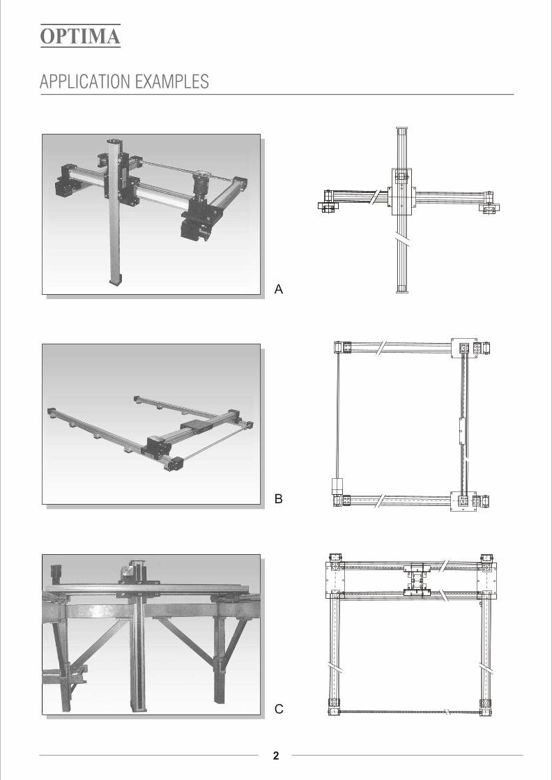
APPLICATION EXAMPLES
2
A
B
C

APPLICATION EXAMPLES
3
XYZ Slide
LFR 20 XY Slide
LMG Slide
Vertical Slide

APPLICATION EXAMPLES
4
Positioner Pipe Slide
Cylinder operating Slide
Positioner Pipe YZ Slide
LMC XY Slide
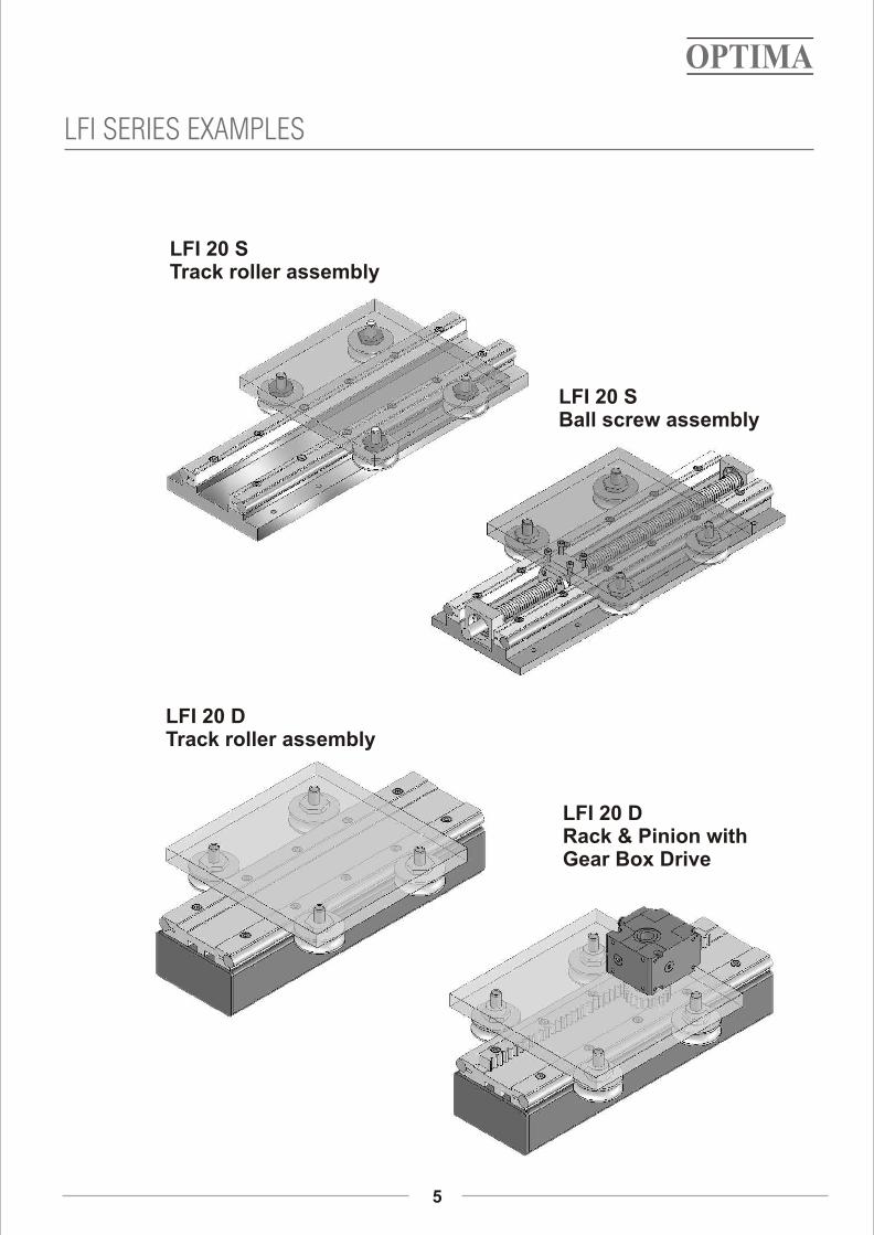
LFI SERIES EXAMPLES
LFI 20 STrack roller assembly
LFI 20 DTrack roller assembly
LFI 20 DRack & Pinion withGear Box Drive
LFI 20 SBall screw assembly
5
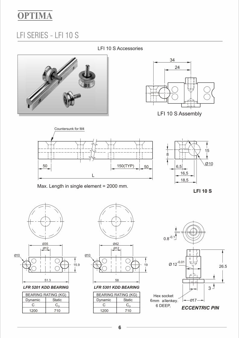
LFI SERIES - LFI 10 S
6
LFI 10 S Accessories
16,5
6,5
15
Ø10
18,5
8
50150(TYP)50
LFI 10 SMax. Length in single element = 2000 mm.
L
Hex socket6mm allenkey.
6 DEEP,
Ø17
26.5Ø 12
0.8
ECCENTRIC PIN
3
-0.1
-0.01
LFR 5301 KDD BEARING
Ø10
58
19
Ø42
Ø12
BEARING RATING (KG)
Dynamic Static
C CO
1200 710
34
24
LFI 10 S Assembly
LFR 5201 KDD BEARING
BEARING RATING (KG)
Dynamic Static
C CO
1200 710
Ø10
51.3
15.9
Ø35
Ø12
Countersunk for M4
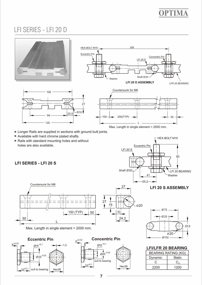
LFI/LFR 20 BEARINGBEARING RATING (KG)
Dynamic Static
C CO
2200 1200
25,8
Ø102
Ø 72
Ø 25
Ø20
Ø16+0.1
±0.133 Hex36
Ø25-0.02
1,5
Eccentric Pin
suit to bearing
8
Concentric Pin
Ø16+0.1
±0.133 Hex36
Ø25-0.02
suit to bearing
8±0.02
±0.02
Max. Length in single element = 2000 mm.
60
M16
55.2
LFI 20 S ASSEMBLY
LFI 20 S
Eccentric Pin
Washer
Shaft Ø20 LFI 20 BEARING
HEX-BOLT
41
7
LFI SERIES - LFI 20 S
LFI SERIES - LFI 20 D
Longer Rails are supplied in sections with ground butt joints.
Available with hard chrome plated shafts.
Rails with standard mounting holes and without
holes are also available.
Eccentric Pin
HEX-BOLT M16
LFI 20 D
Shaft Ø20
LFR 20 BEARING
Washer
LFI 20 D ASSEMBLY
Concentric Pin
208
200(TYP) 50
Max. Length in single element = 2500 mm.
L
100
R10
27
135
9420.5
126
1527
24.2
Ø20
27
50150 (TYP)
50
10
L
Countersunk for M6
Countersunk for M8

LFR-10 EXTERNAL
8
Size LFR 10
E=elastic modulus 7135
I=second moment of area
f=deflection
F=load
L=free length2
(kg/mm )4
(mm )
(mm)
(Kg)
(mm)
Area moment of inertia of aluminium profile
2E-Modul kg/mm
4Ly mm
4Lx mm
7135
56,79x10
56,97 x 10
Forces/torques
Speed
Forces/torques
Fz(Kg)Fx(Kg)dyn Fy(Kg)
(m/sec)max 6
200- 150
Fx(Kg)state
200- 200
Fy(Kg) Fz(Kg)
My (Kgm)Mx (Kgm) Mz (Kgm)
4.3 7.8 12
6.7 13
Mx (Kgm) My (Kgm)
12
Mz (Kgm)
Mx
fy
FxMy
Mz
Fz
ExIx192
3f=FxLF
L
f
L1= 60 + 20 + 160 + 60 + =
L1=END BLOCK+2 LUBRICATION PLATES+TOP PLATE+END BLOCK+STROKE.
4-NOS, M6106
160
63,6
87,3
L1
60
47
47 M5 TAP.
60
86
STOPPER
180
160
106
86
L
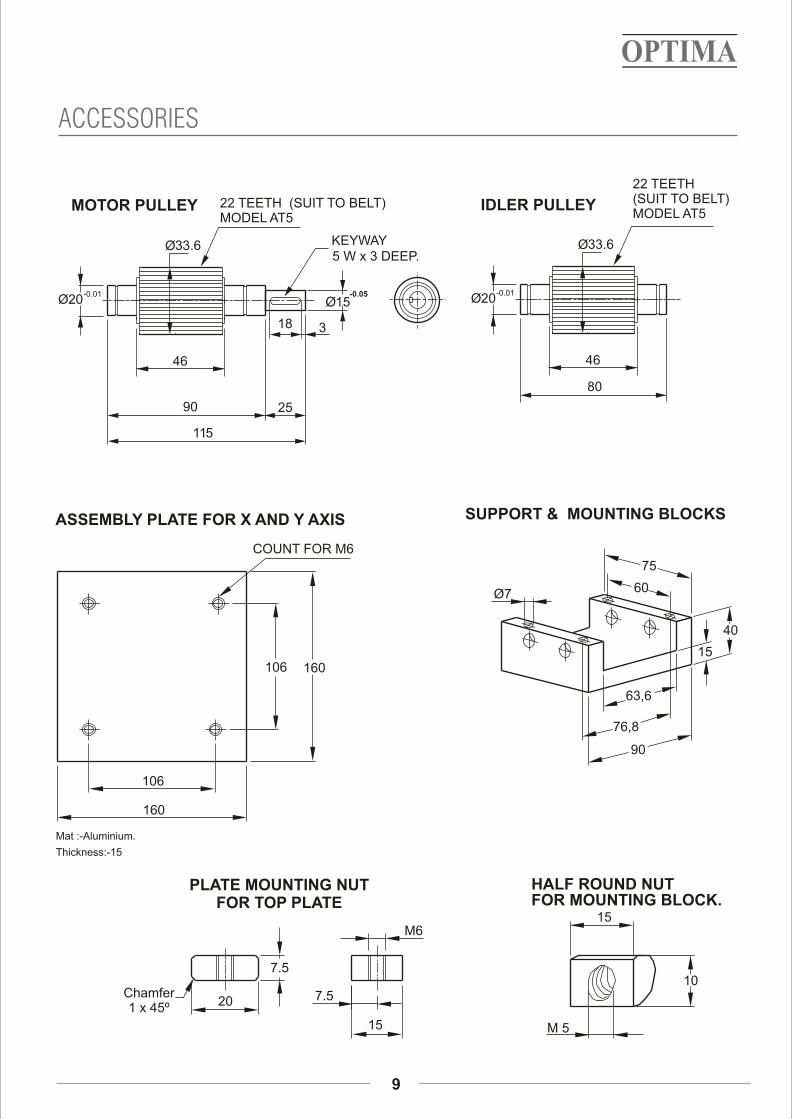
ACCESSORIES
9
Thickness:-15
Mat :-Aluminium.
COUNT FOR M6
106
160
160106
ASSEMBLY PLATE FOR X AND Y AXIS
15
10
M 5
HALF ROUND NUTFOR MOUNTING BLOCK.
PLATE MOUNTING NUTFOR TOP PLATE
Chamfer 1 x 45º 20
7.5
M6
15
7.5
SUPPORT & MOUNTING BLOCKS
63,6
90
75
76,8
60Ø7
40
15
46
Ø33.6
Ø20-0.01
MOTOR PULLEY 22 TEETH (SUIT TO BELT)MODEL AT5
25
Ø15-0.05
KEYWAY5 W x 3 DEEP.
18 3
115
90
46
Ø33.6
Ø20-0.01
22 TEETH(SUIT TO BELT)MODEL AT5
80
IDLER PULLEY

LFR-10 INTERNAL
10
L=END BLOCK+TOP PLATE+STROKE+G.STROKE+END BLOCKL= 62 + 250 + + 25 + 62
My (kgm)
My (kgm)
4Lx mm
2E-Modul N/mm
4Ly mm
7135
Forces/torques
Forces/torques
Speed
Size
Fy(kg)
Area moment of inertia of aluminium profile
(m/sec)max 6
dyn Fx(kg)
-
-
Mx (kgm)Fz(kg)
153
204 204
4.3 7.8
6.7 13
Fy(kg)
LFR 10
state Fx(kg) Mx (kgm)Fz(kg)
Mz (kgm)
12
12
Mz (kgm)
204
56,79x10
56,97x10
250
62
86
62
8660
85,566
86
4-NOS,M5 STOPPER
47
47
L
Mx
Fx
Fz
Mz
My
fy
3f=FxL
ExIx192
f=deflection
F=load
L=free length
E=elastic modulus 7135
I=second moment of area
(mm)
(kg)
(mm)2
(kg/mm )4
(mm )
L
F
f

ACCESSORIES
11
Mounting from above Mounting from below
Ø33,6
46±0.05
22 TEETH (SUIT TO BELT)MODEL AT5
9
60
5.5
11.5
6
5
19,5
47
M5
86
19,5
A
R7,5
6,310,3
Detail : A
46
Ø33.6
Ø20-0.01
MOTOR PULLEY 22 TEETH (SUIT TO BELT)MODEL AT5
25
Ø15-0.05
KEYWAY5 W x 3 DEEP.
18 3
115
90
IDLER PULLEY

LFR-20
12
LFR20 BALLSCREW.
LFR20 TIMER BELT.
75 75
150
200/400(TYP)50/100
300
250
91
23
140
124
55
250
300
BELT=AT10/5
PLATE WITH WIPER &LUBRICATION UNIT
SHEET COVERØ 9 TAP BASEMOUNTING HOLE
4-NOS, M8 TAP TOPMOUNTING HOLE
L
250
300
200/400 (TYP)50/100
44
140
124
23
91
300
250
SHEET COVER Ø9 TAP BASEMOUNTING HOLE
4-NOS, M8 TAP TOPMOUNTING HOLE
MOTOR
BRACKET BALL SCREW
MOUNTING
L
PLATE WITH WIPER &RELUBRICATION FELT.
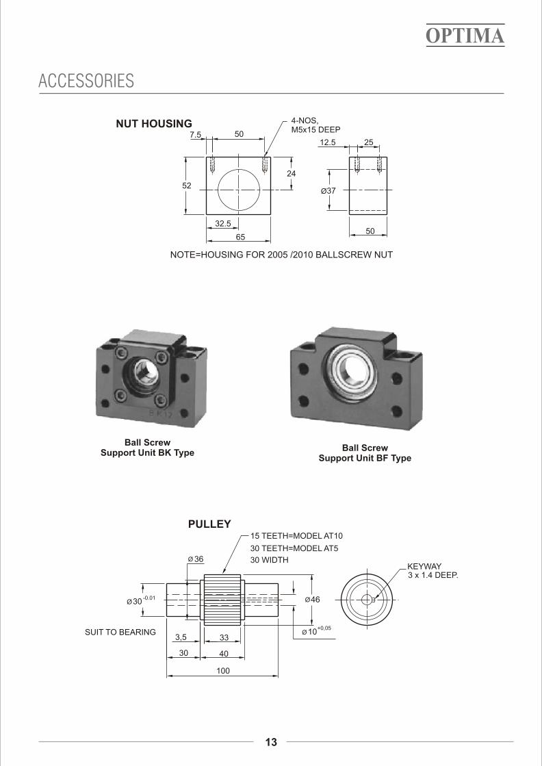
13
ACCESSORIES
Ball Screw Support Unit BK Type
Ball Screw Support Unit BF Type
Ø 10+0,05
Ø 36
3,5
30
100
33
40
Ø30-0.01 Ø46
PULLEY
KEYWAY3 x 1.4 DEEP.
SUIT TO BEARING
30 TEETH=MODEL AT5
30 WIDTH
15 TEETH=MODEL AT10
24
52
6550
Ø37
502512.5
7.5
32.5
4-NOS,M5x15 DEEP
NUT HOUSING
NOTE=HOUSING FOR 2005 /2010 BALLSCREW NUT
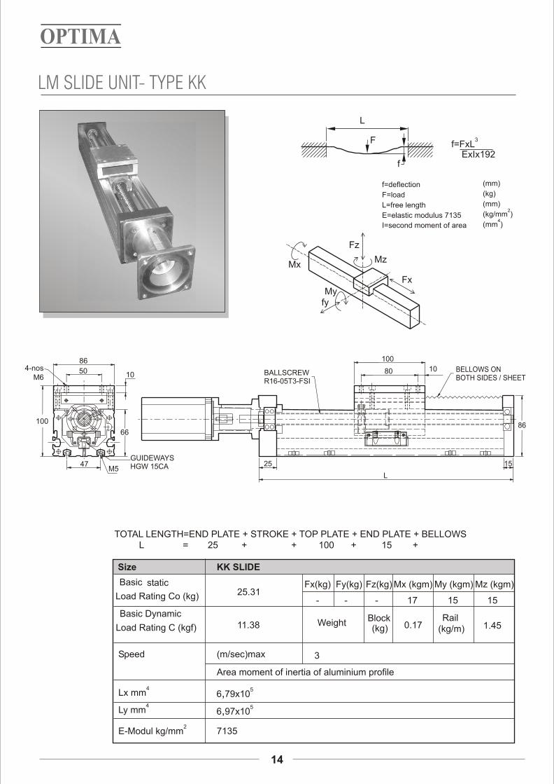
LM SLIDE UNIT- TYPE KK
14
TOTAL LENGTH=END PLATE + STROKE + TOP PLATE + END PLATE + BELLOWS25
My (kgm)
4Lx mm
2E-Modul kg/mm
4Ly mm
7135
Basic Dynamic
Speed
Size
Area moment of inertia of aluminium profile
(m/sec)max 3
25.31- - - 17 15
Fy(kg)
KK SLIDE
Fx(kg) Mx (kgm)Fz(kg)
15
Mz (kgm)
Load Rating C (kgf)Weight
Block(kg) 0.17
Rail(kg/m) 1.45
Load Rating Co (kg)
Basic static
+ + + +100 15
11.38
L =
L
3f=FxL ExIx192
f=deflection
F=load
L=free length
E=elastic modulus 7135
I=second moment of area
(mm)
(kg)
(mm)2
(kg/mm )4
(mm )
F
f
Mx
Fz
Mz
Myfy
Fx
56,79x10
56,97x10
4-nosM6
50
86
10
66
47M5
GUIDEWAYSHGW 15CA
BALLSCREWR16-05T3-FSI
25
L
15
86
80 10
100
BELLOWS ONBOTH SIDES / SHEET
100

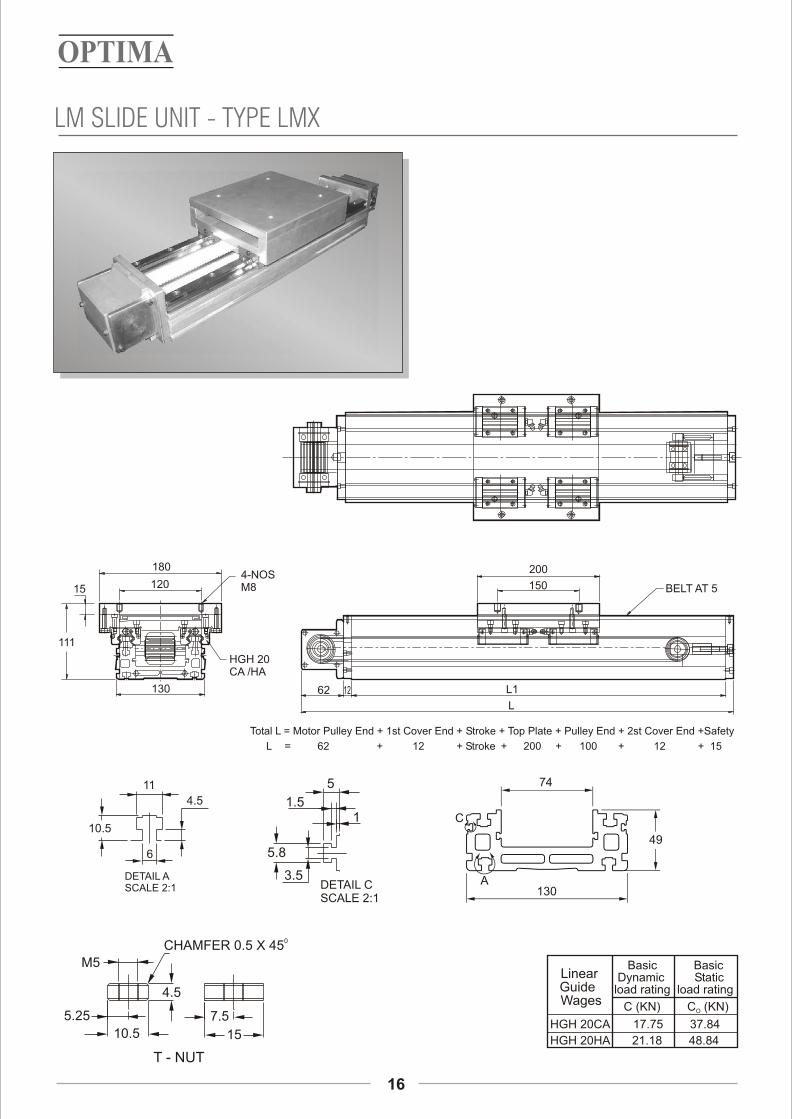
LM SLIDE UNIT - TYPE LMX
15
Basic Basic Dynamic Static load rating load rating
C (KN) C (KN) O
HGH 20CA 17.75 37.84
HGH 20HA 21.18 48.84
Linear Guide
Wages
4.5
11
10.5
6
DETAIL A SCALE 2:1
5
1.5
5.8
3.5DETAIL CSCALE 2:1
1
5.25
10.5
4.5
15
7.5
M5
0CHAMFER 0.5 X 45
T - NUT
74
130
49
C
A
ALS-040-Y(CLAMPING TYPE)COUPLING
MS SHEET (COVER) / BELLOWS
200
15025 R20-05T3-FSIBALL SCREW
L
120
53
180
120
130
HGH20CA /HA
15
4-NOSM8
TOTAL LENGTH=1st END PLATE + STROKE + TOP PLATE + 2nd END PLATE + SAFETY
120 STROKE+ + + + 15200 20L =
LM SLIDE UNIT - TYPE LMX
16
Basic Basic Dynamic Static load rating load rating
C (KN) C (KN) O
HGH 20CA 17.75 37.84
HGH 20HA 21.18 48.84
Linear Guide
Wages
4.5
11
10.5
6
DETAIL A SCALE 2:1
5
1.5
5.8
3.5DETAIL CSCALE 2:1
1
5.25
10.5
4.5
15
7.5
M5
0CHAMFER 0.5 X 45
T - NUT
180
12015
111
HGH 20 CA /HA
130 62 12 L1
150
200
BELT AT 5
L
4-NOSM8
74
130
49
C
A
Total L = Motor Pulley End + 1st Cover End + Stroke + Top Plate + Pulley End + 2st Cover End +Safety
62 Stroke + + + + 15100 12L = + + 20012
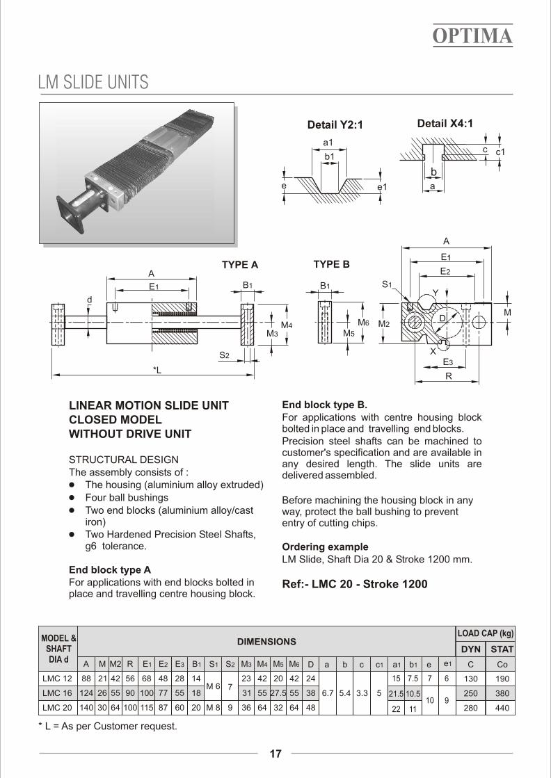
End block type B. LINEAR MOTION SLIDE UNITFor applications with centre housing block CLOSED MODELbolted in place and travelling end blocks.
WITHOUT DRIVE UNITPrecision steel shafts can be machined to customer's specification and are available in
STRUCTURAL DESIGN any desired length. The slide units areThe assembly consists of : delivered assembled.1 The housing (aluminium alloy extruded)
1 Four ball bushings Before machining the housing block in any 1 Two end blocks (aluminium alloy/cast way, protect the ball bushing to prevent
iron) entry of cutting chips.1 Two Hardened Precision Steel Shafts,
g6 tolerance. Ordering example LM Slide, Shaft Dia 20 & Stroke 1200 mm.
End block type AFor applications with end blocks bolted in Ref:- LMC 20 - Stroke 1200place and travelling centre housing block.
DIMENSIONS LOAD CAP (kg)
DYN STAT
C Co
LMC 12
LMC 16
LMC 20
A
88
124
140
M
21
26
30
M2
42
55
64
R
56
90
100
E1
68
100
115
S1
M 6
M 8
E2
48
77
87
M3
23
31
36
MODEL &SHAFTDIA d
E3
28
55
60
B1
14
18
20
S2
7
9
M4
42
55
64
M5
20
27.5
32
M6
42
55
64
* L = As per Customer request.
130 190
250 380
280 440
24
38
48
D a
6.7 5.4
b
3.3
c c1
5
15
21.5
22
a1
7.5
10.5
11
b1
7
10
e
6
e1
9
LM SLIDE UNITS
17
a
c
b
c1a1
b1
e e1
Detail Y2:1 Detail X4:1
18
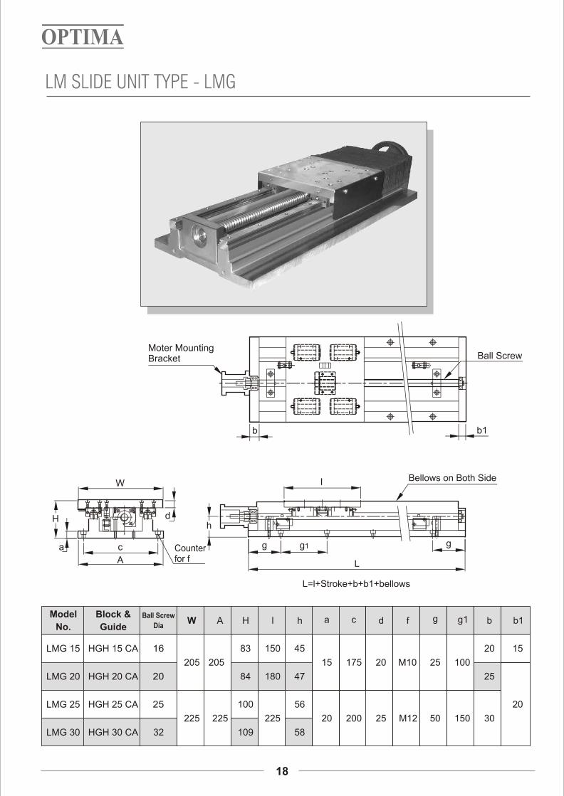
Model
No.
LMG 15
LMG 20
LMG 25
LMG 30
Block &
Guide
HGH 15 CA
HGH 20 CA
HGH 25 CA
HGH 30 CA
Ball Screw
Dia
16
20
25
32
W
205
225
A
205
225
H
83
84
100
109
l
150
180
225
h
45
47
56
58
a
15
20
c
175
200
d
20
25
f
M10
M12
g
25
50
g1
100
150
b
20
25
30
b1
15
20
LM SLIDE UNIT TYPE - LMG
I
19
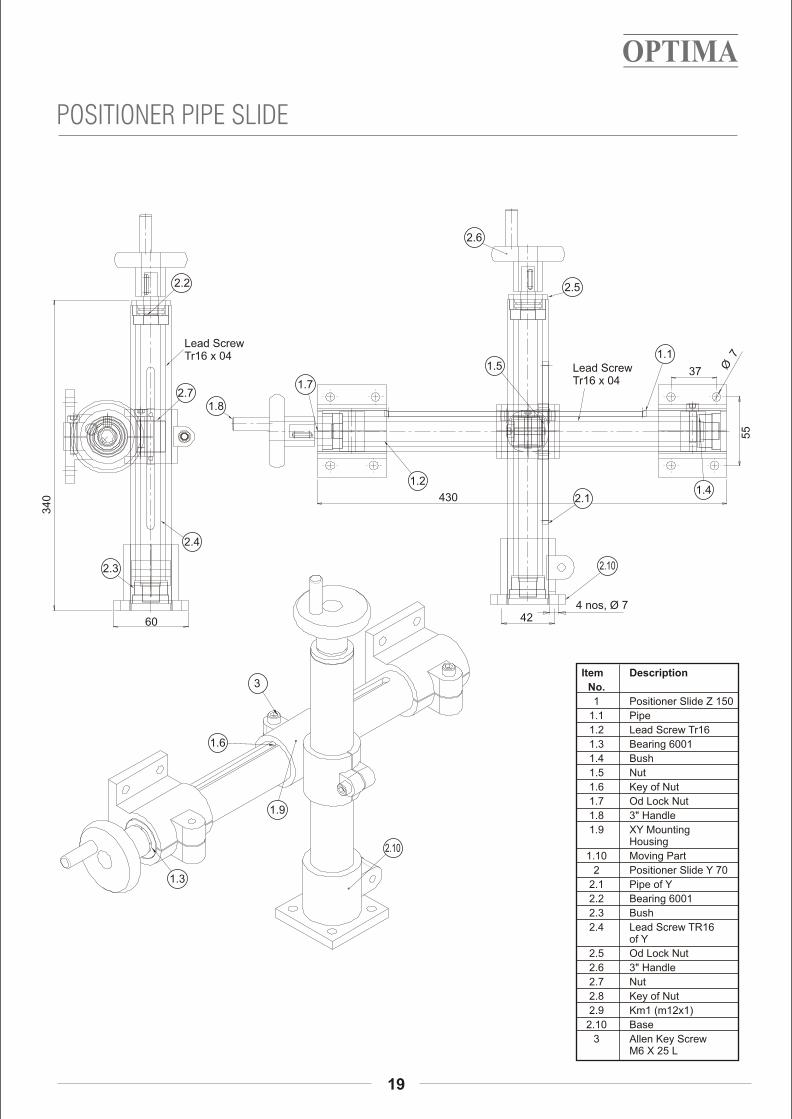
POSITIONER PIPE SLIDE
Item Description
No.
1 Positioner Slide Z 150
1.1 Pipe
1.2 Lead Screw Tr16
1.3 Bearing 6001
1.4 Bush
1.5 Nut
1.6 Key of Nut
1.7 Od Lock Nut
1.8 3" Handle
1.9 XY MountingHousing
1.10 Moving Part
2 Positioner Slide Y 70
2.1 Pipe of Y
2.2 Bearing 6001
2.3 Bush
2.4 Lead Screw TR16of Y
2.5 Od Lock Nut
2.6 3" Handle
2.7 Nut
2.8 Key of Nut
2.9 Km1 (m12x1)
2.10 Base
3 Allen Key ScrewM6 X 25 L
2.2
Lead Screw Tr16 x 04
2.71.7
1.8
1.2
1.5
2.6
2.5
1.1
1.42.1
2.10
2.4
2.3
1.6
2.10
1.9
1.3
34
0
60
37 Ø 7
55
430
424 nos, Ø 7
Lead Screw Tr16 x 04
3

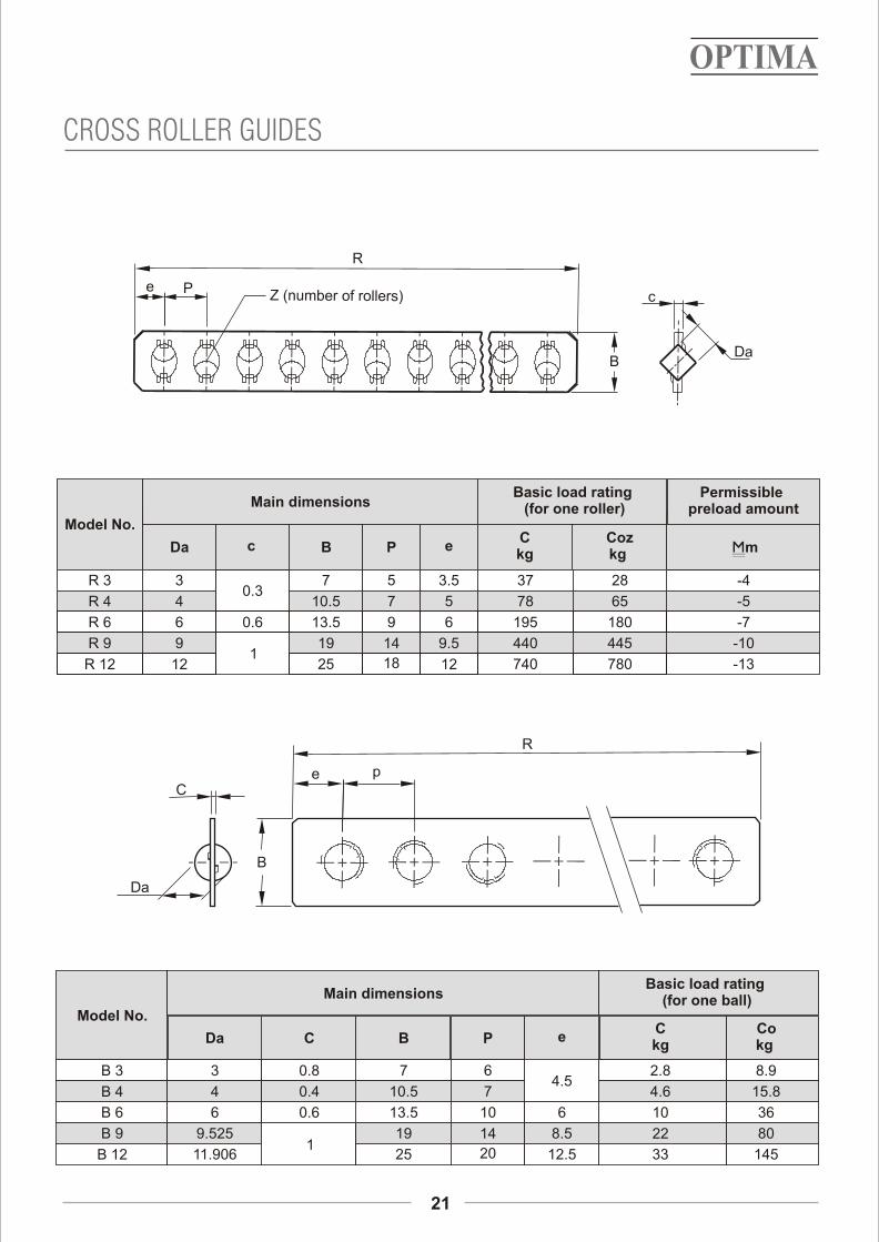
ModelNo.
Rollerdiameter
(balldiameter)
Da
A H W g M d1 d2 h
Main dimensions
Length L[Number of rollers per
roller cage (Z)]F E
kg/m
t
R 3
R 4
R 6
R 9
R 12
3
4
6
9
12
18
22
31
44
58
8
11
15
22
28
8.3
10
14
20.2
26.9
3.5
4.5
6
9
12
M4
M5
M6
M8
M10
3.3
4.3
5.3
6.8
8.5
6
7.5
9.5
10.5
13.5
3.1
4.1
5.2
6.2
8.2
25
40
50
100
12.5
20
25
50
2
3
R
(1) 42, (2) 62, (3) 82, (4) 102, (5) 122 (6) 142, (7) 162, (8) 182,
(9) 202, (10) 222, (11)242
(1) 73, (2) 101, (3) 136, (4) 164, (5) 199, (6) 227, (7) 262, (8) 297,
(9) 325, (10) 360, (11)388
(1) 84, (2) 129, (3) 165, (4) 210, (5) 246, (6) 282, (7) 327, (8) 363,
(9) 408, (10) 444, (11)489.
(1) 173, (2)257, (3) 327, (4) 411, (5) 495, (6) 565, (7) 649, (8) 733,
(9) 817, (10)887, (11) 971.
(1) 168, (2) 258, (3) 330, (4) 420, (5) 492, (6) 564, (7) 654, (8) 726,
(9) 816, (10) 888, (11) 978
(1) 50(8), (2) 75(12), (3) 100(16), (4) 125(20), (5) 150(24) (6) 175(28),
(7) 200(32), (8) 225(36), (9) 250(40), (10) 275(44), (11)300(48)
(1) 80(10), (2) 120(14), (3) 160(19), (4) 200(23), (5) 240(28), (6) 280(32), (7) 320(37), (8) 360(42), (9) 400(46),
(10) 440(51), (11)480(55)
(1) 100(9), (2) 150(14), (3) 200(18), (4) 250(23), (5) 300(27), (6) 350(31), (7) 400(36), (8) 450(40), (9) 500(45),
(10) 550(49), (11)600(54).
(1) 200(9), (2)300(14), (3) 400(18), (4) 500(23), (5) 600(27), (6) 700(31), (7) 800(36), (8) 900(40), (9) 1000(45),
(10)1100(49), (11) 1200(54).
(1) 200(9), (2) 300(14), (3) 400(18), (4) 500(23), (5) 600(27), (6) 700(31), (7) 800(36), (8) 900(40), (9) 1000(45),
(10) 1100(49), (11) 1200(54)
Mass (Ref)
0.5
0.82
1.57
3.3
5.57
Roller2Cage( )
g
1Way( )
2.96
6.91
20.3
64.8
9.46
Note:- The values in brackets for the dimension A show the dimensions for combination with the Ball cage type B.1 ( ) This value shows mass per one meter for individual way. 2 ( ) This value shows mass of one roller cage in which ten rollers are incorporated.
CROSS ROLLER GUIDES
20
L
EFEt
A
w
M
gd1h
d2
t H
Da C B P eC kg
Co kg
B 3
B 4
B 6
B 9
B 12
3
4
6
9.525
11.906
7
10.5
13.5
19
25
6
7
10
14
20
4.5
6
8.5
12.5
2.8
4.6
10
22
33
8.9
15.8
36
80
145
R 3
R 4
R 6
R 9
R 12
3
4
6
9
12
0.3
0.6
1
7
10.5
13.5
19
25
5
7
9
14
18
3.5
5
6
9.5
12
37
78
195
440
740
28
65
180
445
780
-4
-5
-7
-10
-13
Model No.
mm
Main dimensionsBasic load rating (for one roller)
Permissible preload amount
Da c B P eC kg
Coz kg
Model No.
Main dimensionsBasic load rating
(for one ball)
0.8
0.4
0.6
1
21
CROSS ROLLER GUIDES
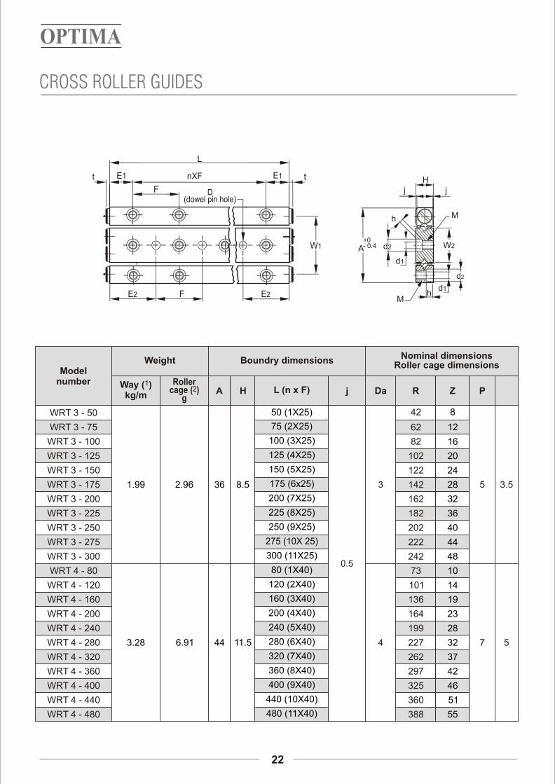
Model number
Weight Boundry dimensionsNominal dimensions
Roller cage dimensions
1Way ( )kg/m
Roller2cage ( )
gA H L (n x F) j Da R Z P
WRT 3 - 50
WRT 3 - 75
WRT 3 - 100
WRT 3 - 125
WRT 3 - 150
WRT 3 - 175
WRT 3 - 200
WRT 3 - 225
WRT 3 - 250
WRT 3 - 275
WRT 3 - 300
WRT 4 - 80
WRT 4 - 120
WRT 4 - 160
WRT 4 - 200
WRT 4 - 240
WRT 4 - 280
WRT 4 - 320
WRT 4 - 360
WRT 4 - 400
WRT 4 - 440
WRT 4 - 480
1.99
3.28
2.96
6.91
36
44
8.5
11.5
50 (1X25)
75 (2X25)
100 (3X25)
125 (4X25)
150 (5X25)
175 (6x25)
200 (7X25)
225 (8X25)
250 (9X25)
275 (10X 25)
300 (11X25)
80 (1X40)
120 (2X40)
160 (3X40)
200 (4X40)
240 (5X40)
280 (6X40)
320 (7X40)
360 (8X40)
400 (9X40)
440 (10X40)
480 (11X40)
0.5
3
4
42
82
102
122
142
162
182
202
222
242
73
101
136
164
199
227
262
297
325
360
388
8
62 12
16
20
24
28
32
36
40
44
48
10
14
19
23
28
32
37
42
46
51
55
5
7
3.5
22
CROSS ROLLER GUIDES
5

Mounting dimensions
D Tolerance
t
Basic dynamic
load rating 3C ( )
kg
Basic static
load rating 3Co ( )
kg
Allowable load
3Fu ( ) kg
29
35
16.6
20
12.5
20
25
40
M4
M5
3.3
4.3
6
7.5
3.1
4.1
4+0.01200.0000
5+0.01200.0000
2
68
130
62
120
21
40
W1 W2 E1 E2 M d1 d2 h
23
CROSS ROLLER GUIDES

24
100
load, improved performance. Most importantly, the FRICTIONLESS TABLES Frictionless tables offer designers additional frictionless tables provide high accuracy and
flexibility in their choice of ready to install repeatability. Their overall performance is better
components for precision linear motion. The than ball slides especially in applications where
crossed roller slides, when compared to other loads must be moved in compact assemblies.
products of equal size, offer higher load carrying Further these slides can be made light weight using
capacity & when operating at high cycle rates or with aluminium carriage and aluminium base.
shock and over hanging
Model No.
NK3 - 55
NK3 - 80
NK3 - 105
NK3 - 130
NK3 - 155
NK3 - 180
NK3 - 205
NK6 - 110
NK6 - 160
NK6 - 210
NK6 - 260
NK6 - 310
NK6 - 360
NK6 - 410
NK9 - 210
NK9 - 310
NK9 - 410
NK9 - 510
NK9 - 610
NK9 - 710
NK9 - 810
A
28
45
60
BStroke
S
30
45
60
75
90
105
130
60
95
130
165
200
235
265
130
180
350
450
550
650
750
n1
-
15
20
n
5.5
8
11
L
55
80
105
130
155
180
205
110
160
210
260
310
360
410
210
310
410
510
610
710
810
L1
1x25
2x25
3x25
4x25
5x25
6x25
7x25
1x50
2x50
3x50
4x50
5x50
6x50
7x50
1x100
2x100
3x100
4x100
5x100
6x100
7x100
L2
15
30
55
L3
-
1x25
2x25
3x25
4x25
5x25
6x25-
1x50
2x50
3x50
4x50
5x50
6x50-
1x100
2x100
3x100
4x100
5x100
6x100
L4
27.5
55
105
L5
5.5
10.5
15.5
20.5
25.5
30.5
30.5
16.5
24
31.5
39
46.5
54
64
27
52
17
60
145
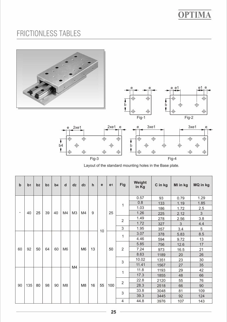
FRICTIONLESS TABLES
d3d2Counter for d
Top plateBase plate
n
b2 b b1B b4
n1
h
AA0.1
b3
L
L3
=
L4
=L5
L4
L5
L1L2 L2
-
60
90
b b1
40
92
135
b2
25
50
80
b3
39
64
98
Fig
1
2
3
1
2
3
1
2
3
4
Weight in Kg
0.570.8
1.03
1.26
1.49
1.72
1.95
3.07
4.46
5.85
7.24
8.63
10.02
11.41
11.8
17.3
22.8
28.3
33.8
39.3
44.8
C in kg
93
133
186
225
278
327
357
378
594
756
973
1189
1351
1567
1193
1855
2120
2518
3048
3445
3976
Ml in kg MQ in kgd
M4
M6
M8
M3 M4 9 25
10
M4
M6 13 50
M8 16 55 100
d2 d3 h e e1b4
40
60
90
0.79
1.19
1.72
2.12
2.56
3
3.4
5.83
9.72
12.6
16.5
20
23
27
29
48
55
66
81
92
107
1.29
1.85
2.5
3
3.8
4.4
5
8.5
13
17
21
26
30
35
42
66
76
90
109
124
143
25
FRICTIONLESS TABLES
Layout of the standard mounting holes in the Base plate.
Fig-3 Fig-4
Fig-2Fig-1
2xe1
b4
e 3xe1
b
e2xe1 e 3xe1 e
e
b
e1e1 ee e
b
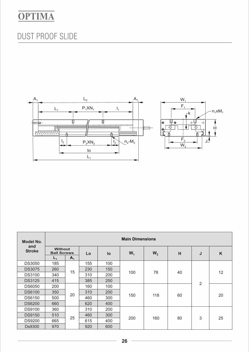
Model No. and
Stroke
DS3050
DS3075
DS3100
DS3125
DS6050
DS6100
DS6150
DS6200
DS9100
DS9150
DS9200
Ds9300
185
260
340
415
200
350
500
660
360
510
665
970
15
20
25
Without Ball Screws
L1 A1
Lo
155
230
310
385
160
310
460
620
310
460
615
920
100
150
200
250
100
200
300
400
200
300
400
600
lo
Main Dimensions
W 1 W2 H J K
100 78 40 12
150 118 60
2
20
200 160 80 3 25
26
DUST PROOF SLIDE
l1
I2
L0
L1
XNP2 2I2
L1
A1
P XN1 1
A1
lo
n -M22
k
H
JW2
F2
W1
F1
xn M1 1
Base Mounting HolesTop Mounting Holes
l1 P xN xF 1 1 1 n 1 M 1 l 2 P xN xF 2 2 2
n 2 M2
52.5 50 x 1 x 50 4
6
80 50 x 3 x 50 8
10
30 50 x 2 x 80
105 50 x 2 x 80 6
130 50 x 4 x 80 10
160 50 x 6 x 80 14
80 50 x 3 x 100
155 50 x 3 x 100 8
182.5 50 x 5 x 100 12
260 100 x 4 x 100 10
65 50 x 2 x 50
92.5 50 x 4 x 50
M5 25
M6
M8
50
50 x 1 x 65 4
50 x 2 x 65 6
50 x 3 x 65 8
50 x 4 x 65 10
50 x 1 x 95 4
50 x 2 x 95 6
50 x 4 x 95 10
50 x 6 x 95 14
100 x 1 x 130 4
100 x 2 x 130 6
100 x 3 x 130 8
100 x 5 x 130 12
4.1
5.7
7.4
9.1
10.2
17.6
25.1
32.8
31.6
44.4
58.4
83.3
M5
M6
M8
Total Weight
KgF
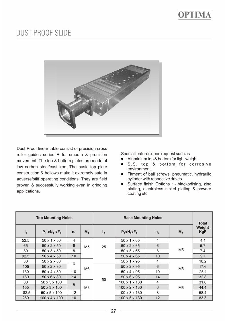
Dust Proof linear table consist of precision cross Special features upon request such asroller guides series R for smooth & precision Aluminium top & bottom for light weight.movement. The top & bottom plates are made of S . S . t o p & b o t t o m f o r c o r r o s i v e
low carbon steel/cast iron. The basic top plate environment.construction & bellows make it extremely safe in Fitment of ball screws, pneumatic, hydraulic
cylinder with respective drives.adverse/stiff operating conditions. They are field Surface finish Options : - blackodising, zinc proven & successfully working even in grinding
plating, electroless nickel plating & powder applications.
coating etc.
1
1
1
1
DUST PROOF SLIDE
27

Features:Needle roller guides type N/O1 High load carrying capacity.
1 Low co-efficient of friction.The guides are hardened (60-62 Hrc) and can 1 Light and compact design.be used with needle rollers in steel /plastic
cages. One Set includes:N/O guides are useful for accurate positioning 1 2 N railsand inspection systems. 1 2 O railsThese work both in horizontal & vertical 1 4 end piecesapplication.
1 Plastic/steel cage needle
roller bearing elements.
BearingNumber
Dimensions
Da A B L d h M d1 F G E g g1 C
N/O
92025
N/O
2025
N/O
2535
N/O
3045
2
2.5
3
44
52
62
74
22
25
30
35
200 300 400 500
600 700 800
200 300 400 500
600 700 800 1000
300 400 500
600 700 800 1000
400 500
600 700 800 1000
10.5
13.5
16.5
18.5
6.2
8.2
10.2
12.2
M 8
M 10
M 12
M 14
6.8
8.5
10.5
12.5
50 100
9
10
12
14
24
28
34
42.5
24.5
29
35
40
15
18
22
25
Note : Longer lengths upon request.
M + V GUIDES
28
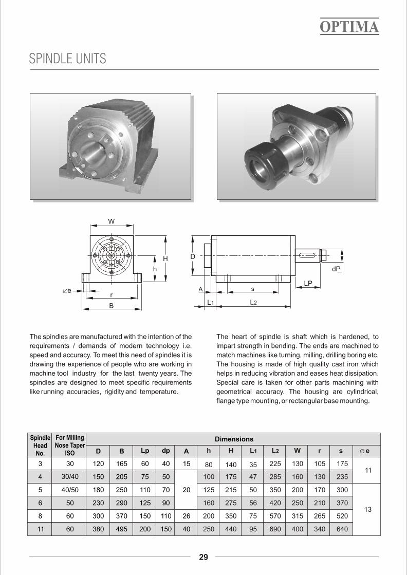
The spindles are manufactured with the intention of the The heart of spindle is shaft which is hardened, to
requirements / demands of modern technology i.e. impart strength in bending. The ends are machined to
speed and accuracy. To meet this need of spindles it is match machines like turning, milling, drilling boring etc.
drawing the experience of people who are working in The housing is made of high quality cast iron which
machine tool industry for the last twenty years. The helps in reducing vibration and eases heat dissipation.
spindles are designed to meet specific requirements Special care is taken for other parts machining with
like running accuracies, rigidity and temperature. geometrical accuracy. The housing are cylindrical,
flange type mounting, or rectangular base mounting.
3
4
5
6
8
11
30
30/40
40/50
50
60
60
D
120
150
180
230
300
380
B
165
205
250
290
370
495
Lp
60
75
110
125
150
200
dp
40
50
70
90
110
150
A
15
20
26
40
Spindle Head No.
For Milling Nose Taper
ISO
Dimensions
h H L1 L2
80
100
125
160
200
250
140
175
215
275
350
440
35
47
50
56
75
95
225
285
350
420
570
690
r
105
130
170
210
265
340
W
130
160
200
250
315
400
s e
175
235
300
370
520
640
11
13
SPINDLE UNITS
29
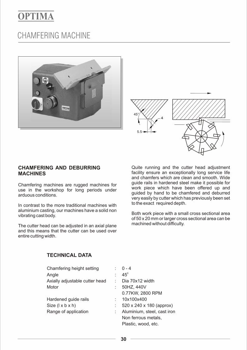
Quite running and the cutter head adjustment CHAMFERING AND DEBURRINGfacility ensure an exceptionally long service life MACHINESand chamfers which are clean and smooth. Wide guide rails in hardened steel make it possible for Chamfering machines are rugged machines for work piece which have been offered up and use in the workshop for long periods under guided by hand to be chamfered and deburred arduous conditions.very easily by cutter which has previously been set to the exact required depth.In contrast to the more traditional machines with
aluminium casting, our machines have a solid non Both work piece with a small cross sectional area vibrating cast body.of 50 x 20 mm or larger cross sectional area can be machined without difficulty.The cutter head can be adjusted in an axial plane
and this means that the cutter can be used over entire cutting width.
TECHNICAL DATA
Chamfering height setting : 0 - 40
Angle : 45
Axially adjustable cutter head : Dia 70x12 width
Motor : 50HZ, 440V
0.77KW, 2800 RPM
Hardened guide rails : 10x100x400
Size (l x b x h) : 520 x 240 x 180 (approx)
Range of application : Aluminium, steel, cast iron
Non ferrous metals,
Plastic, wood, etc.
CHAMFERING MACHINE
30
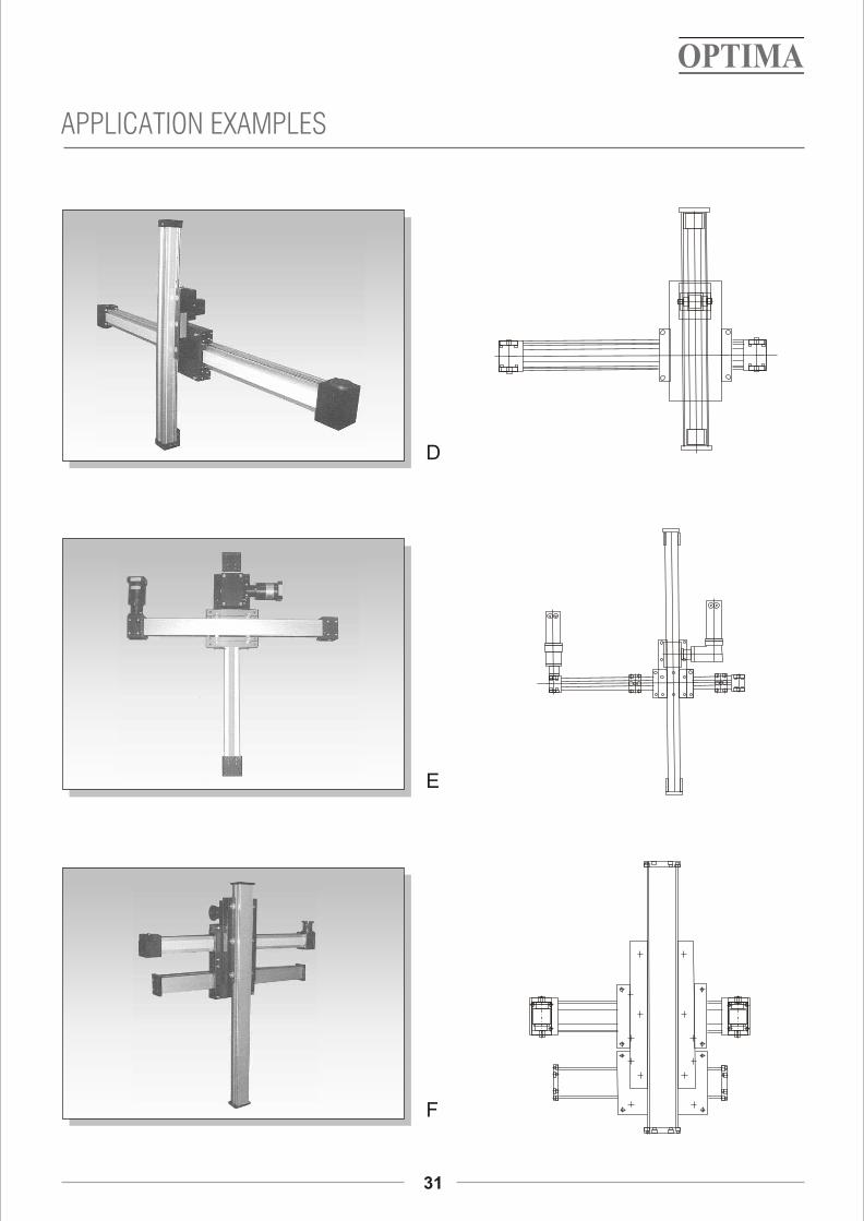
APPLICATION EXAMPLES
31
D
E
F
32
REQUEST FORM
Request for quotation
Customer Name Date :
Phone :
Address Fax :
Email :
Country :
Delivery Point:
Quantity :
Desired Delivery Date:
Type of Slide 1. Horizontal
2. Vertical
3. 3 Axis (X,Y,Z)
Required Specification
1. Slide Name
2. Load
3. Stroke
4. Application
i) Horizontal
ii) Vertical
iii) 3 Axis (X,Y,Z)
5. Speed
6. Motor Power
7. R.P.M.
8. Acceleration
9. Gear Box
10. Accuracy
11. V.F.D.
Customer special requirements
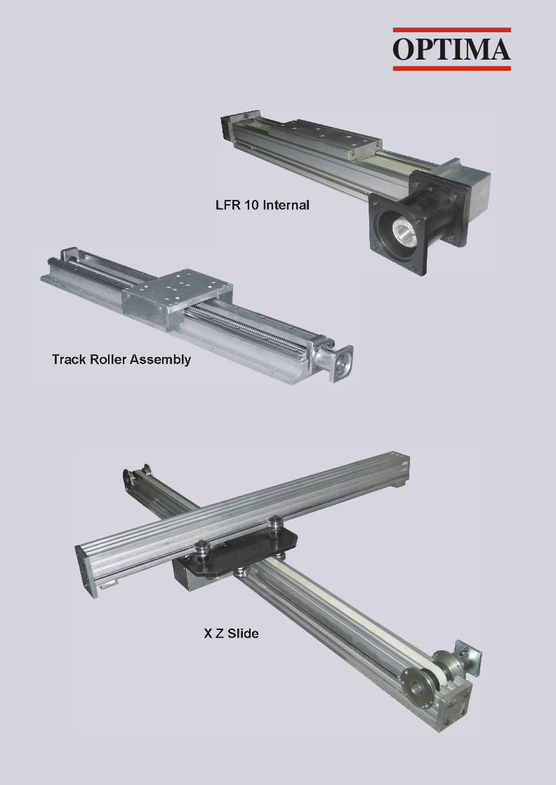
Track Roller Assembly
X Z Slide
LFR 10 Internal
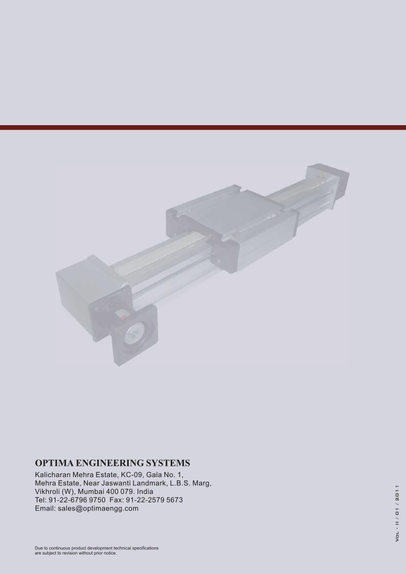
Kalicharan Mehra Estate, KC-09, Gala No. 1, Mehra Estate, Near Jaswanti Landmark, L.B.S. Marg, Vikhroli (W), Mumbai 400 079. IndiaTel: 91-22-6796 9750 Fax: 91-22-2579 5673Email: [email protected]
OPTIMA ENGINEERING SYSTEMS
Vol - II / 01 / 2
011