linear to success. - bibusnew.bibus.cz/pdf/danmot_tollo_neff/shg_e.pdf · 4 what requirements must...
TRANSCRIPT

Linear to success.Movement starts in the head and then has to be con-
sistently turned into innovative product solutions of a
high technical standard. As a first-class supplier of
components for electrically powered linear technology,
NEFF offers carefully designed standard products that
can be flexibly modified to suit individual customer
requirements. In-house development and research,
design and production combined with total quality
management guarantee that our versatile product
range and complete accessory programme meet the
highest possible standards. Our international sales
division with the NEFF Business Service is always
ready to help – consulting advice, help with product
selection and carrying out repairs – worldwide.
Worm gear screw jacks MULIa, JUMBOa 4–7Requirements and solutions . . . . . . . . . . . . . . . . . . . . . . . . . . . . . . . . . . . . . . . . . . . . . . . . . .4Systematic gear technology . . . . . . . . . . . . . . . . . . . . . . . . . . . . . . . . . . . . . . . . . . . . . . . . . . .5Selection of worm gear screw jacks . . . . . . . . . . . . . . . . . . . . . . . . . . . . . . . . . . . . . . . . . . .6–7
Technical data MULIa, JUMBOa 8–23Design versions . . . . . . . . . . . . . . . . . . . . . . . . . . . . . . . . . . . . . . . . . . . . . . . . . . . . . . . . .10–11General technical data . . . . . . . . . . . . . . . . . . . . . . . . . . . . . . . . . . . . . . . . . . . . . . . . . . . .12–13Dimensions, version N, V . . . . . . . . . . . . . . . . . . . . . . . . . . . . . . . . . . . . . . . . . . . . . . . . . . . .14Dimensions, version R . . . . . . . . . . . . . . . . . . . . . . . . . . . . . . . . . . . . . . . . . . . . . . . . . . . . . .15Accessories trapezoidal screw nuts . . . . . . . . . . . . . . . . . . . . . . . . . . . . . . . . . . . . . . . . . . . .16Accessories ball screw nuts . . . . . . . . . . . . . . . . . . . . . . . . . . . . . . . . . . . . . . . . . . . . . . . . . .17Accessories mounting feet L, trunnion mountings K . . . . . . . . . . . . . . . . . . . . . . . . . . . . . .18Accessories universal joint adapter KAR, adapter bracket KON . . . . . . . . . . . . . . . . . . . . . .19Accessories top plate BP, fork end GA . . . . . . . . . . . . . . . . . . . . . . . . . . . . . . . . . . . . . . . . . .20Accessories clevis end GK . . . . . . . . . . . . . . . . . . . . . . . . . . . . . . . . . . . . . . . . . . . . . . . . . . . .21Accessories bellows F . . . . . . . . . . . . . . . . . . . . . . . . . . . . . . . . . . . . . . . . . . . . . . . . . . . . . . .22Accessories limit switches ES . . . . . . . . . . . . . . . . . . . . . . . . . . . . . . . . . . . . . . . . . . . . . . . . .23
Drive technology 24–43Motor adapter flanges MG . . . . . . . . . . . . . . . . . . . . . . . . . . . . . . . . . . . . . . . . . . . . . . . .26–273-phrase motors M . . . . . . . . . . . . . . . . . . . . . . . . . . . . . . . . . . . . . . . . . . . . . . . . . . . . . .28–29Flexible couplings RA, RG . . . . . . . . . . . . . . . . . . . . . . . . . . . . . . . . . . . . . . . . . . . . . . . . . . . .30Handwheels HR . . . . . . . . . . . . . . . . . . . . . . . . . . . . . . . . . . . . . . . . . . . . . . . . . . . . . . . . . . . .31Pillow blocks UKP . . . . . . . . . . . . . . . . . . . . . . . . . . . . . . . . . . . . . . . . . . . . . . . . . . . . . . . . . .32Safety nuts SFM . . . . . . . . . . . . . . . . . . . . . . . . . . . . . . . . . . . . . . . . . . . . . . . . . . . . . . . . . . .33Bevel gear boxes KRG . . . . . . . . . . . . . . . . . . . . . . . . . . . . . . . . . . . . . . . . . . . . . . . . . . . .34–40Universal joint shafts GX . . . . . . . . . . . . . . . . . . . . . . . . . . . . . . . . . . . . . . . . . . . . . . . . . .41–42Connecting shafts VW . . . . . . . . . . . . . . . . . . . . . . . . . . . . . . . . . . . . . . . . . . . . . . . . . . . . . .43
Drive sizing 44–54Sizing and selection . . . . . . . . . . . . . . . . . . . . . . . . . . . . . . . . . . . . . . . . . . . . . . . . . . . . . . . .44Examples for the direction of rotation . . . . . . . . . . . . . . . . . . . . . . . . . . . . . . . . . . . . . . . . .45Selecting a worm gear screw jack and corresponding drive unit . . . . . . . . . . . . . . . . . . . .46Duty circle and drive power . . . . . . . . . . . . . . . . . . . . . . . . . . . . . . . . . . . . . . . . . . . . . . . . . .47Critical buckling force of a screw jack under compressive loads . . . . . . . . . . . . . . . . . . . . .48Critical speed of the worm gear screw jack . . . . . . . . . . . . . . . . . . . . . . . . . . . . . . . . . . . . .49Required drive torque . . . . . . . . . . . . . . . . . . . . . . . . . . . . . . . . . . . . . . . . . . . . . . . . . . . . . .50Drive sizing . . . . . . . . . . . . . . . . . . . . . . . . . . . . . . . . . . . . . . . . . . . . . . . . . . . . . . . . . . . . . . .51Performance tables for MULIa worm gear screw jack . . . . . . . . . . . . . . . . . . . . . . . . . . . . .52Performance tables for JUMBOa worm gear screw jack . . . . . . . . . . . . . . . . . . . . . . . . . . .53Installation and maintenance . . . . . . . . . . . . . . . . . . . . . . . . . . . . . . . . . . . . . . . . . . . . . . . . .54
Order Code 55Inquiry data MULIa, JUMBOa 56NEFF International 57–58
Contents
4
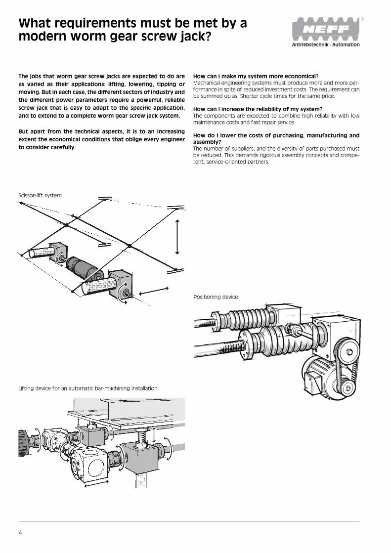
What requirements must be met by amodern worm gear screw jack?
The jobs that worm gear screw jacks are expected to do are
as varied as their applications: lifting, lowering, tipping or
moving. But in each case, the different sectors of industry and
the different power parameters require a powerful, reliable
screw jack that is easy to adapt to the specific application,
and to extend to a complete worm gear screw jack system.
But apart from the technical aspects, it is to an increasing
extent the economical conditions that oblige every engineer
to consider carefully:
How can I make my system more economical?Mechanical engineering systems must produce more and more per-formance in spite of reduced investment costs. The requirement canbe summed up as: Shorter cycle times for the same price.
How can I increase the reliability of my system?The components are expected to combine high reliability with lowmaintenance costs and fast repair service.
How do I lower the costs of purchasing, manufacturing andassembly?The number of suppliers, and the diversity of parts purchased mustbe reduced. This demands rigorous assembly concepts and compe-tent, service-oriented partners.
Scissor-lift system
Lifting device for an automatic bar-machining installation
Positioning device

5
NEFF worm gear screw jacks:Systematic gear technology
The MULI ®, JUMBO® worm gear screw jack program stands for
reliability in use and versatility in application. Technically
matured, and with its easy-to-mount, rectangular housing, it
can easily be extended to form wide-area jack systems with
the help of its wide range of accessories. And last but not
least, the heart of every NEFF screw jack is a precision trape-
zoidal or ball screw drive in acknowledged high quality from
our own screw production.
You will find the answers here:
■ The comprehensive portfolio offers a wide range of types andsizes of gears. These permit even heavy loads to be moved at highspeed.
■ The consistent high quality of the com-ponents used, rationalised manufac-turing and the NEFF 24-hour repair ser-vice guarantee smooth, reliable use ofyour machine.
■ We undertake the entire dimensioningof the jack system for you, includingthe drive technology. And you are savedthe time-consuming procurement oflots of individual components.

6
Selection of worm gear screw jacksThe optimum solution for every application
Axially translating screwThe rotary motion of precisionworm gearing (worm shaftand internally threaded wormwheel) is converted into axiallinear motion of the screw,which travels/translatesthrough the gear box housing.The load is attached to theend of the screw.
Rotating screwDriven by a precision wormgearing (screw keyed to theworm wheel), the rotarymotion of the screw is trans-lated into linear motion of thetravelling nut on the screw.
MULI® 1 to MULI® 5(5 –100 kN)
JUMBO® 1 toJUMBO® 5(150–500 kN)
Version N
Version V
Version R

7
Version N
Rotation of the screw isprevented by its permanentattachment to the guidedload.
Version V
Version V with anti-rotationdevice is recommended ifthe srew cannot be securedexternally to prevent rota-tion.
Version R
Gear ratio H
One full turn of the wormshaft produces a stroke of1mm.
Trapeziodal screw
For tough conditions, goodprice/performance ratio.
Gear ratio L
One full turn of the wormshaft produces a stroke of0.25 mm.
Ball srew
For longer duty cycles, withhigher efficiency, highpositional accuracy.

Surveying axles for rodlocomotives, Hörmann Railway Technology,Germany

Worm gear screw jacksMULI®, JUMBO®
9
NEFF worm gear screw jacks ofthe MULI® and JUMBO® seriesare manufactured for loadsfrom 5 to 500kN. All models aredesigned for both pushing andpulling forces, and for position-independent functioning.
The cubic housing, standardisedmounting material and end-pieces, and pre-drilled flangeholes permit the ideal installa-tion of motor, gears and shaftencoder.
Synchronisation of severalworm gear screw jacks is simplewith the complete range ofaccessories.

10
Axially translatingscrewVersion N or V
The rotary motion of precisionworm gearing (worm shaft andinternally threaded worm wheel)is converted into axial linearmotion of the screw, whichtravels/translates through thegear box housing. The load isattached to the end of thescrew.
Functional DesignThe cubic housing with its pre-drilled flange holes makes forsimple mounting, and allowslonger power-on times.Because the heat is moreefficiently dissipated, ensuringlonger lubricant lifetimes.
Lubrication of theWorm WheelRadial lubrication holes in theworm wheel grease thetrapezoidal screw. The resultant lower friction andwarming lead to an increasedlifetime, especially in the caseof longer strokes.
Heavy Duty BearingsRadial deep-groove ball bear-ings (Muli® 1–3) and conicalroller bearings (Muli® 4+5 andJUMBO® 1–5) on the screw shaftmake it possible to handleheavy loads. Axial ball bearingsas the main pressure bearings(for all sizes) give a large safetymargin, and increase the overalllifetime.
Overview of NEFF worm gear screw jacksDesign versions
➀
➄
➃
➂ a ➂ b
➂ a
➁
➁➀

11
Housing MaterialThe housing in aluminium (Muli® 1+2) or highly stablespheroidal graphite cast iron(Muli® 3 and higher) providesmore stability, especially athigher temperatures. Thisprovides a safety margin, even under rugged conditions.
Rotating screwVersion R
Driven by a precision wormgearing (screw keyed to theworm wheel), the rotary motionof the screw is translated intolinear motion of the travellingnut on the screw.
Central LubricationThe worm gear screw jack isconveniently lubricated at onepoint. Maintenance – whethermanual or automatic – is child’splay.
Heavy Duty BearingsRadial deep-groove ball bear-ings (Muli® 1– 3) and conicalroller bearings (Muli® 4+5 andJUMBO® 1–5) on the screw shaftmake it possible to handleheavy loads. Axial ball bearingsas the main pressure bearings(for all sizes) give a large safetymargin, and increase the overalllifetime.
➀
➄
➄
➃
➃
➂ a ➂ b
➂ b
12
Tolerances andbacklash■ The gearbox housings are
machined on the four moun-ting sides. The tolerancesconform to DIN ISO 2768-mH.The sides that are not machi-ned (the cooling ribs) con-form to DIN 1688-T1/GTA 16for MULI® 1+2, DIN 1685, GTB 18–GGG-40 from MULI® 3.
■ The axial backlash of the jackscrew under alternating loadis as follows:– Trapezoidal screws:
up to 0.4 mm (to DIN 103)– Ball screws: 0.08 mm.
■ The lateral play between theoutside diameter of the screwand the guide diameter is0.2mm.
■ The backlash in the wormgears is ±4 ° for gear ratio Land ±1° for gear ratio H.
■ Trapezoidal screws are manu-factured to a straightness of0.3–1.5 mm/m, ball screws toa straightness of 0.08mm/mover a length of 1000mmand to the following pitchaccuracies:MULIa 1–MULIa 5:0.05 mm/300 mm lengthJUMBOa 1–JUMBOa 5:0.2 mm/300 mm length.
Lateral forces on the jackscrew.Any lateral forces that mayoccur should be taken by anexternal guide rail.
MULI®, JUMBO®
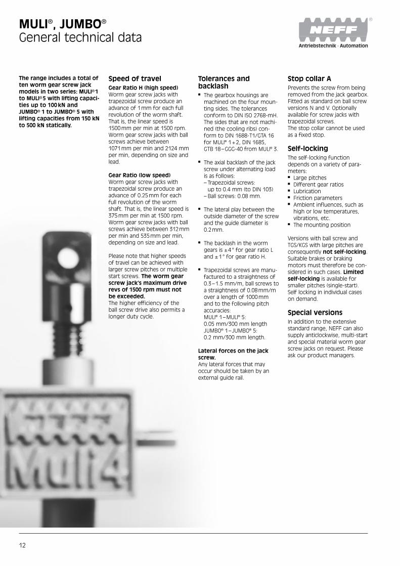
General technical data
The range includes a total often worm gear screw jackmodels in two series: MULIa1to MULIa5 with lifting capaci-ties up to 100 kN andJUMBOa 1 to JUMBOa 5 withlifting capacities from 150 kNto 500 kN statically.
Speed of travelGear Ratio H (high speed)Worm gear screw jacks withtrapezoidal screw produce anadvance of 1mm for each fullrevolution of the worm shaft.That is, the linear speed is1500mm per min at 1500 rpm.Worm gear screw jacks with ballscrews achieve between1071mm per min and 2124 mmper min, depending on size andlead.
Gear Ratio (low speed)Worm gear screw jacks withtrapezoidal screw produce anadvance of 0.25mm for eachfull revolution of the wormshaft. That is, the linear speed is375mm per min at 1500 rpm.Worm gear screw jacks with ballscrews achieve between 312mmper min and 535mm per min,depending on size and lead.
Please note that higher speedsof travel can be achieved withlarger screw pitches or multiplestart screws. The worm gearscrew jack’s maximum driverevs of 1500 rpm must notbe exceeded.The higher efficiency of theball screw drive also permits alonger duty cycle.
Stop collar APrevents the screw from beingremoved from the jack gearbox.Fitted as standard on ball screwversions N and V. Optionallyavailable for screw jacks withtrapezoidal screws.The stop collar cannot be usedas a fixed stop.
Self-lockingThe self-locking functiondepends on a variety of para-meters:■ Large pitches■ Different gear ratios■ Lubrication■ Friction parameters■ Ambient influences, such as
high or low temperatures,vibrations, etc.
■ The mounting position
Versions with ball screw andTGS/KGS with large pitches areconsequently not self-locking.Suitable brakes or brakingmotors must therefore be con-sidered in such cases. Limitedself-locking is available forsmaller pitches (single-start).Self locking in individual caseson demand.
Special versionsIn addition to the extensivestandard range, NEFF can alsosupply anticlockwise, multi-startand special material worm gearscrew jacks on request. Pleaseask our product managers.

13
MULI®, JUMBO®
General technical data
Trapezoidal srews
MULI 1 MULI 2 MULI 3 MULI 4 MULI 5 JUMBO 1 JUMBO 2 JUMBO 3 JUMBO 4 JUMBO 5
Maximum lifting capacity [kN]1) 5 10 25 50 100 150 200 250 350 500
Screw diameter and pitch [mm] 18 x 4 20 x 4 30 x 6 40 x 7 55 x 9 60 x 9 70 x 10 80 x 10 100 x 10 120 x 14
Stroke in mm per full turn Ratio H2) 1 1 1 1 1 1 1 1 1 1
of the worm shaft [mm] Ratio L2) 0.25 0.25 0.25 0.25 0.25 0.25 0.25 0.25 0.25 0.25
Gear ratio Ratio H2) 4:1 4:1 6:1 7:1 9:1 9:1 10:1 10:1 10:1 14:1
Ratio L2) 16:1 16:1 24:1 28:1 36:1 36:1 40:1 40:1 40:1 56:1
Efficiency [%]3) Ratio H2) 31 29 29 26 24 23 22 20 19 19
Ratio L2) 25 23 23 21 19 18 17 15 15 15
Weight [kg] (zero stroke) 1,2 2,1 6 17 32 41 57 57 85 160
Weight [kg per 100 mm stroke] 0.26 0.42 1.14 1.67 3.04 3.1 4.45 6.13 7.9 11.5
Idling torque [Nm] H 0.04 0.11 0.15 0.35 0.84 0.88 1.28 1.32 1.62 1.98
L 0.03 0.10 0.12 0.25 0.51 0.57 0.92 0.97 1.10 1.42
Housing material G – AL GGG – 40
Ball screws
MULI 1 MULI 2 MULI 3 MULI 4 MULI 5 JUMBO 3
Maximum lifting capacity [kN]1) 5 10 12.5 22 42 65 78
Screw diameter and pitch [mm] 1605 2005 2505 4005 4010 5010 8010
Stroke in mm per full turn Ratio H2) 1.25 1.25 0.83 0.71 1.43 1.1 1
of the worm shaft [mm] Ratio L2) 0.31 0.31 0.21 0.18 0.36 0.28 0.25
Gear ratio Ratio H2) 4:1 4:1 6:1 7:1 9:1 10:1
Ratio L2) 16:1 16:1 24:1 28:1 36:1 40:1
Efficiency [%]3) Ratio H2) 57 56 55 53 56 47 45
Ratio L2) 46 44 43 43 45 37 34
Weight [kg] (zero stroke) 1.3 2.3 7 19 35 63
Weight [kg per 100 mm stroke] 0.26 0.42 1.14 1.67 3.04 6.13
Idling torque [Nm] H 0.04 0.11 0.15 0.35 0.84 1.32
L 0.03 0.10 0.12 0.25 0.51 0.97
Housing material G – AL GGG – 40
2) H=high travel speed,L= low travel speed.
Note:Initial breakaway torque:approx. 2–3 times nominaltorque in run-up (FU operation!)
1) Dependent on speed of stroke,power-on time, etc. (see p. 12)
Order-Code see page 55
3) The specified efficiency values areaverage values.

14
MULI®, JUMBO®
Dimensions, versions N, V
Size Dimensions [mm]
A11) A2 A3 a1 a2 B1 B2 B3 B4 b1 b2 b3 b4 b5 C1 C2 C32)
MULI 1 80 25 24 60 10 24 72 120 77 52 18 3 13 1.5 20 62 35(46)
MULI 2 100 32 28 78 11 27.5 85 140 90 63 20 5 15 1.5 30 75 45(48.5)
MULI 3 130 45 31 106 12 45 105 195 110 81 36 5 15 2 30 82 50
MULI 4 180 63 39 150 15 47.5 145 240 150 115 36 6 16 2 45 117 65
MULI 5 200 71 46 166 17 67.5 165 300 170 131 56 8 30 2.5 55 160 95
JUMBO 1 210 71 49 170 20 65 195 325 200 155 56 8 40 8 55 175 95
JUMBO 2 240 80 60 190 25 67.5 220 355 225 170 56 8 45 8 55 165 110
JUMBO 3 240 80 60 190 25 67.5 220 355 225 170 56 8 45 8 55 165 110
JUMBO 4 290 100 65 230 30 65 250 380 255 190 56 10 54 8 65 220 140
JUMBO 5 360 135 75 290 35 100 300 500 305 230 90 14 80 8 90 266 200
Size Dimensions [mm]
C43) C5 C6 D1k64) D25) D36) D4Tr D4KGT D53) D6 D7H7 D8 D9xb67) R (TK)7) V-KGT5)
MULI 1 12(23) 19 31 10 x 21.5 32 M12 x 1.75 Tr18 x 4 1605 29.6(48) M8 28 12 M5 x 8 32 (45.25) 30 x 30
MULI 2 18(21.5) 20 37.5 14 x 25 40 M14 x 2.0 Tr20 x 4 2005 38.7(61) M8 35 15 M6 x 9 35 (49.5) 40 x 40
MULI 3 23 22 41 16 x 42.5 50 M20 x 2.5 Tr30 x 6 2505 46 M10 35 17 M8 x 10 44 (62.2) 50 x 50
MULI 4 32 29 58.5 20 x 45 60 M30 x 3.5 Tr40 x 7 4005/4010 60 M12 52 25 M10 x 14 55 (77.8) 60 x 60
MULI 5 40 48 80 25 x 65 82 M36 x 4 Tr55 x 9 5010 85 M20 52 28 M12 x 16 60 (84.85) 80 x 80
JUMBO 1 40 48 87.5 25 x 62.5 90 M48 x 2 Tr60 x 9 – 90 M24 52 28 M12 x 16 60 (84.85) –
JUMBO 2 40 58 82.5 30 x 65 115 M56 x 2 Tr70 x 10 – 105 M30 58 32 M12 x 18 (80) –
JUMBO 3 40 58 82.5 30 x 65 115 M64 x 3 Tr80 x 10 8010 120 M30 58 32 M12 x 18 (80) 120 x 120
JUMBO 4 50 78 110 35 x 62.5 133 M72 x 3 Tr100 x 10 – 145 M36 72 40 M16 x 30 (100) –
JUMBO 5 60 118 133 48 x 97.5 153 M100 x 3 Tr120 x 14 – 170 M42 80 50 M16 x 40 (115) –
1) Dimension A1 for MULI 1+2 toDIN 1688-T1/GTA 16, from MULI 3 toDIN 1685 GTB 18.
Order-Code see page 55
2) This dimension refers to the closedheight and represents a minimum. It must be increased if bellows areused (see page 22).
3) The values in brackets refer toversion with ball screw.
4) Diameter and length to shoulder.5) Square tube for version with ball
screw and anti-rotation device.
6) In accordance to DIN 13 screw thread:MULI. In accordance to DIN 13 fine pitchthread: JUMBO.
7) JUMBO 2–5 only 3 holes.
Grease nipple
Effective stroke + C1
D6
(4x
per
side
)
If attachments are to be fitted, please specify on which side (A/B)!
Note:Subject to change without notice.
15
MULI®, JUMBO®
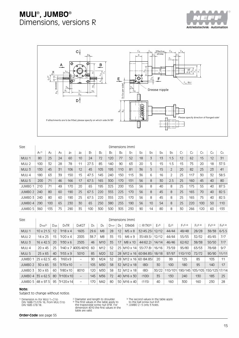
Dimensions, versions R
Size Dimensions [mm]
A11) A2 A3 a1 a2 B1 B2 B3 B4 b1 b2 b3 b4 b5 C1 C2 C3 C4 C6
MULI 1 80 25 24 60 10 24 72 120 77 52 18 3 13 1.5 12 62 15 12 31
MULI 2 100 32 28 78 11 27.5 85 140 90 63 20 5 15 1.5 15 75 20 18 37.5
MULI 3 130 45 31 106 12 45 105 195 110 81 36 5 15 2 20 82 25 23 41
MULI 4 180 63 39 150 15 47.5 145 240 150 115 36 6 16 2 25 117 30 32 58.5
MULI 5 200 71 46 166 17 67.5 165 300 170 131 56 8 30 2.5 25 160 45 40 80
JUMBO 1 210 71 49 170 20 65 195 325 200 155 56 8 40 8 25 175 55 40 87.5
JUMBO 2 240 80 60 190 25 67.5 220 355 225 170 56 8 45 8 25 165 70 40 82.5
JUMBO 3 240 80 60 190 25 67.5 220 355 225 170 56 8 45 8 25 165 75 40 82.5
JUMBO 4 290 100 65 230 30 65 250 380 255 190 56 10 54 8 25 220 100 50 110
JUMBO 5 360 135 75 290 35 100 300 500 305 230 90 14 80 8 30 266 120 60 133
Size Dimensions [mm]
D1k62) D2j6 D4TR D4KGT D5 D6 D7H7 D8 D9xb6 R (TK)5) E13) E23) F13) 4) F23) 4) F33) 4) F43) 4)
MULI 1 10 x 21.5 12 Tr18 x 4 1605 29.6 M8 28 12 M5 x 8 32 (45.25) 12/12 44/44 48/48 28/28 38/38 6/5.5
MULI 2 14 x 25 15 Tr20 x 4 2005 38.7 M8 35 15 M6 x 9 35 (49.5) 12/12 44/44 55/55 32/32 45/45 7/7
MULI 3 16 x 42.5 20 Tr30 x 6 2505 46 M10 35 17 M8 x 10 44 (62.2) 14/14 46/46 62/62 38/38 50/50 7/7
MULI 4 20 x 45 25 Tr40 x 7 4005/4010 60 M12 52 25 M10 x 14 55 (77.8) 16/16 73/59 95/80 63/53 78/68 9/7
MULI 5 25 x 65 40 Tr55 x 9 5010 85 M20 52 28 M12 x 16 60 (84.85) 18/18 97/97 110/110 72/72 90/90 11/11
JUMBO 1 25 x 62.5 45 Tr60x9 – 90 M24 52 28 M12 x 16 60 (84.85) 20 99 125 85 105 11
JUMBO 2 30 x 65 55 Tr70x10 – 105 M30 58 32 M12 x 18 (80) 30 100 180 95 140 17
JUMBO 3 30 x 65 60 Tr80x10 8010 120 M30 58 32 M12 x 18 (80) 30/22 110/101 190/145 105/105 150/125 17/14
JUMBO 4 35 x 62.5 80 Tr100x10 – 145 M36 72 40 M16 x 30 (100) 35 130 240 130 185 25
JUMBO 5 48 x 97.5 95 Tr120x14 – 170 M42 80 50 M16 x 40 (115) 40 160 300 160 230 28
4) The second values in the table applyto the ball screw nut KGF.
5) JUMBO 2–5 only 3 holes.
1) Dimension A1 for MULI 1+2 toDIN 1688-T1/GTA 16, from MULI 3 toDIN 1685 GTB 18.
Order-Code see page 55
2) Diameter and length to shoulder.3) The first values in the table apply to
the trapezoidal screw nut EFM. Fordimension 4010 the first values in thetable are valid.
Effectivestroke
Grease nipple
D6
(4x
per
side
)If attachments are to be fitted, please specify on which side (A/B)!
Please specify direction of flanged side!
Note:Subject to change without notice.

16
Complete bronze nutEFM
For drive units in continuousoperation with particularly goodwear properties. Can be used assafety nut; “sea water resistant”in combination with stainlessscrews. EFM nuts have thesame dimensions as ball nutsKGF-N and can therefore befitted together with the nutmountings KON-N and KAR-N.Material:G-CuSn 7 ZnPg (Rg 7)∂B =269 N/mm2; HB 10=75
Accessories MULI®, JUMBO®
Trapezoidal nuts
Adapter for attach-ment of the secondbellows
Version R only
Size Type/Size Dimensions [mm]
D1h9 D4 D5 6xD6 L1 L2 L3 L4 L5
MULI 1 EFM Tr 18 x 4 28 48 38 6 44 12 8 15 20
MULI 2 EFM Tr 20 x 4 32 55 45 7 44 12 8 15 20
MULI 3 EFM Tr 30 x 6 38 62 50 7 46 14 8 20 25
MULI 4 EFM Tr 40 x 7 63 95 78 9 73 16 10 20 25
MULI 5 EFM Tr 55 x 9 72 110 90 11 97 18 10 20 25
JUMBO 1 EFM Tr 60 x 9 85 125 105 11 99 20 10 20 25
JUMBO 2 EFM Tr 70 x 10 95 180 140 17 100 30 16 20 25
JUMBO 3 EFM Tr 80 x 10 105 190 150 17 110 30 16 20 25
JUMBO 4 EFM Tr 100 x 10 130 240 185 25 130 35 16 25 30
JUMBO 5 EFM Tr 120 x 14 160 300 230 28 160 40 20 30 35
Order-Code see page 55

17
Flanged ball nut KGFFlanged ball screw nut withmounting and lubrication holesand with profiled gaskets(reduces lubricant leakage andprevents ingress of dirt particles)for ball screw KGS.Material: 1.7131 (ESP 65).Note:For KSG version, please specifyinstallation direction of nut.
Zero-backlash units KGT-FF/KGT-MM/KGT-FMFactory adjusted and assembledcombinations of two cylindricalnuts (MM), two flanged nuts(FF) or one flanged and onecylindrical nut (FM). Only avail-able as screw mechanism, i.e.nut preassembled on thecorresponding ball screw.
Accessories MULI®, JUMBO®
Ball nuts
1) Dynamic load rating to DIN 69051Part 4, draft version 1978.
2) Dynamic load rating to DIN 69051Part 4, draft version 1989.
3) EE=rubber wiper
Adapter for attach-ment of the secondbellow
Version R only
Size Type/ Dimensions [mm] Axial No. Load rating [kN]Diameter [mm]/ backlash ofLead [mm]/ D1 D4 D5 D6 L1 L2 L4 L5 L7 L9 L10 G max. circuits C1) C2) Co =Coa
[mm]
MULI 1 KGF-N 1605 RH-EE3) 28 38 5.5 48 8 44 15 20 12 8 6 M6 0.08 3 12.0 9.3 13.1
MULI 2 KGF-N 2005 RH-EE3) 32 45 7 55 8 44 15 20 12 8 6 M6 0.08 3 14.0 10.5 16.6
MULI 3 KGF-N 2505 RH-EE3) 38 50 7 62 8 46 20 25 14 8 7 M6 0.08 3 15.0 12.3 22.5
MULI 4 KGF-N 4005 RH-EE3) 53 68 7 80 10 59 20 25 16 8 8 M6 0.08 5 26.0 23.8 63.1
MULI 4 KGF-N 4010 RH-EE3) 63 78 9 95 10 73 20 25 16 8 8 M8x1 0.08 3 50.0 38.0 69.1
MULI 5 KGF-N 5010 RH-EE3) 72 90 11 110 10 97 20 25 18 8 9 M8x1 0.08 5 78.0 68.7 155.8
JUMBO 3 KGF-N 8010 RH-EE3) 105 125 14 145 10 101 20 25 22 8 11 M8x1 0.08 5 93.0 86.2 262.4
Order-Code see page 55

18
Supplied loose with mountingbolts for jack. Burnished. Muli 1+2 with version N-KGTnot on side F. Standard: side E.(see page 14/15)
Mounting feet L
Accessories MULI®, JUMBO®
Mountings
Supplied loose with mountingbolts for jack. Burnished.Standard: side E.Side F please specify.(see page 14/15)
Trunnion mountings K
Size Dimensions [mm] WeightA1 A2 A3 A4 A5 A6 A7 A8 [kg]
L MULI 1 72 52 8.5 20 100 120 10 10 0.3
L MULI 2 85 63 8.5 20 120 140 10 10 0.4
L MULI 3 105 81 11 24 150 170 10 12 0.8
L MULI 4 145 115 13.5 30 204 230 13 16 1.7
L MULI 5 171 131 22 40 236 270 17 25 3.9
L JUMBO 1 205 155 26 50 250 290 20 30 5.8
L JUMBO 2 230 170 32 65 290 340 25 40 10
L JUMBO 3 230 170 32 65 290 340 25 40 10
L JUMBO 4 270 190 39 80 350 410 30 50 20.8
L JUMBO 5 330 230 45 100 430 500 35 60 34.4
Size Dimensions [mm] WeightL1 L2 L3 L4 L5 L6 Df8 D1 D2 B [kg]
K MULI 1 110 80 49 9 72 13 15 44 18 20 0.76
K MULI 2 140 100 60 10 85 18 20 58 23 25 1.44
K MULI 3 170 130 76 11 105 18 25 72 28 30 2.80
K MULI 4 240 180 102 12 145 28 35 86 38 40 7.40
K MULI 5 270 200 117 17 165 33 45 115 48 50 10.72
K JUMBO 1 290 210 120 15 195 38 50 130 56 60 11.8
K JUMBO 2 330 240 140 20 220 43 70 170 76 80 26.1
K JUMBO 3 330 240 140 20 220 43 70 170 76 80 26.1
K JUMBO 4 410 290 165 20 250 58 80 160 88 90 40.2
K JUMBO 5 520 360 210 30 300 78 90 175 96 100 67.7

19
Accessories MULI®, JUMBO®
Mountings
Universal joint adapterKAR
Size Type Dimensions [mm] Weightfor KGF for EFM A2 B1 B2 B3 C1 D1 D4 G x T [kg]
KAR MULI 1 KAR 1605 Tr 16x4/Tr 18x4 12 70 50 10 20 28 38 M5x10 0.20
KAR MULI 2 KAR 2005 Tr 20x4/Tr 24x4 16 85 58 13.5 25 32 45 M6x12 0.30
KAR MULI 3 KAR 2505 Tr 30x6 18 95 65 15 25 38 50 M6x12 0.50
KAR MULI 4 KAR 4005 25 125 85 20 30 53 68 M6x12 1.20
KAR 4010 Tr 40x7 30 140 100 20 40 63 78 M8x14 2.50
KAR MULI 5 KAR 5010 Tr 55x9 40 165 115 25 50 72 90 M10x16 2.80
KAR JUMBO 1 KAR 6310 Tr 60x9 40 180 130 25 50 85 105 M10x16 3.30
KAR JUMBO 3 KAR 8010 50 200 150 25 60 105 125 M12x18 4.80
Universal joint adapter for trun-nion mounting of flanged ballnut KGF and flanged trapezoidalnut EFM.
Material:1.0065 (St37) or 1.0507 (St52)
Adapter bracket KONAdapter bracket for the radialfixing of flanged ball nut KGF.
Material:1.0065 (St37) or 1.0507 (St52)
Type for KGF Dimensions [mm]
A1 A2 max1) A2 min B1 B2 C1 C2 C41) D1 D4 G x T
KON 1605 60 35 25 50 34 40 24 M 8x15 28 38 M 5x10
KON 2005 68 37.5 29 58 39 40 24 M 8x15 32 45 M 6x12
KON 2020/2050 75 42.5 32.5 65 49 40 24 M 10x15 35 50 M 6x12
KON 2505 75 42.5 32.5 65 49 40 24 M 10x15 38 50 M 6x12
KON 3205 82 45 37 75 54 50 30 M 10x12 45 58 M 6x12
KON 3210/3240/4005 92 50 42 85 60 50 30 M 12x15 53 68 M 6x12
KON 4010 120 70 50 100 76 65 41 M 14x25 63 78 M 8x14
KON 5010 135 77.5 57.5 115 91 88 64 M 16x25 72 90 M 10x16
KON 6310 152 87.5 65 130 101 88 64 M 16x30 85 105 M 10x16
1) Standard = A2 max (delivery status)

20
Accessories MULI®, JUMBO®
Attachments
Screwed onto the mountingthread of the jack screw andprotected against rotation.Supplied with split pins andcollar pins. Galvanized.Standard: Collar pin mountedparallel to the drive shaft.Note: Please specify alignmentat version V.
Fork end GA
Size Dimensions [mm] WeightG2 G3 G4H9 G5 ❋ G6B12 G7 G8 G9 G10 G11 [kg]
GA MULI 1 48 24 12 24 12 M5 M12 18 62 20 0.15
GA MULI 2 56 28 14 28 14 M6 M14 22 72 24.5 0.2
GA MULI 3 80 40 20 40 20 M8 M20 30 105 34 0.8
GA MULI 4 120 60 30 60 30 M8 M30 43 160 52 2.5
GA MULI 5 144 72 35 70 35 M10 M36 54 188 60 3.8
Screwed onto the mountingthread of the jack screw andprotected against rotation.Standard: Hole-pattern BP sym-metrically to SHG housing.Note: Please specify alignmentat version V.
Top plate BP
Size Dimensions [mm] WeightB1 B2 ø B3 B4 B5 B6 B7x4 B8 [kg]
BP MULI 1 20 7 65 48 29.3 M12 9 M5 0.2
BP MULI 2 21 8 80 60 38.7 M14 11 M6 0.3
BP MULI 3 23 10 90 67 46 M20 11 M8 0.6
BP MULI 4 30 15 110 85 60 M30 13 M8 1.2
BP MULI 5 50 20 150 117 85 M36 17 M10 4.8
BP JUMBO 1 50 25 170 130 90 M48x2 21 M10 5
BP JUMBO 2 60 30 200 155 105 M56x2 25 M12 7.7
BP JUMBO 3 60 30 220 170 120 M64x3 25 M12 9.8
BP JUMBO 4 80 40 260 205 145 M72x3 32 M12 18.4
BP JUMBO 5 120 40 310 240 170 M100x3 38 M12 29.6

21
Screwed onto the mountingthread of the jack screw andprotected against rotation.Standard: Collar pin mountedparallel to the drive shaft.Note: Please specify alignmentat version V.
Clevis end GK
Accessories MULI®, JUMBO®
Attachments
Size Dimensions [mm] WeightG1 G2 G3 G4H8 G6H10 G7 G8 G9 [kg]
GK MULI 1 55 40 15 10 15 30 M12 M5 0.2
GK MULI 2 63 45 18 12 20 39 M14 M6 0.3
GK MULI 3 78 53 20 16 30 45 M20 M8 0.6
GK MULI 4 100 70 30 20 35 60 M30 M8 1.2
GK MULI 5 130 97 33 22 40 85 M36 M10 2.5
GK JUMBO 1 120 75 45 40 60 90 M48x2 M10 4.8
GK JUMBO 2 130 90 50 50 70 105 M56x2 M12 4.8
GK JUMBO 3 155 105 60 60 80 120 M64x3 M12 8.0
GK JUMBO 4 220 135 85 80 110 145 M72x3 M12 22.5
GK JUMBO 5 300 200 100 90 120 170 M100x3 M12 31.5

22
Bellows FBellow cover for protectionagainst external influences.Suitable for horizontal or verti-cal installation.Material: PVC-coated polyester,stitched construction.Temperature range -30 °C to70 °C.Calculation: For each 150mmof open length up to 1.80mallow 8mm when calculatingthe closed length. Allow 10mmfor each 150mm over 1.80m.The calculated length is addedto value C3 (see page 14) as thescrew extension. Diameter F2 may differ on theopposite side, depending onthe attachment fitted.
Installation:Installation position must bespecified: horizontal installationrequires internal support wash-ers; in the case of vertical instal-lation, bellows over 2m havetextile strips. Attachment is byhose clamps.Note: Version R (rotating screw)includes two bellows with bel-lows holder (please specifyinstallation details for secondbellows, see pp. 14/15). Theattachment of the second bel-lows at the end of the screw iscarried out by the customer.Please always specify the flangedirection of the nut.
Spiral spring covers SFAvailable on request (refer alsoto the catalogue Screw Drivespage 30/31).
Accessories MULI®, JUMBO®
Protection
Size Dimensions [mm]
For design F1 F2 F3 F4
F MULI 1 N/V TGS1) 12 30 30 101
N/V KGS1) 12 48 30 101
R 12 30 28 101
F MULI 2 N/V TGS1) 12 39 39 113
N/V KGS1) 12 61 39 113
R 12 39 32 113
F MULI 3 N/V 20 46 46 127
R 20 46 38 127
F MULI 4 N/V 20 60 60 140
R TGS/KGS-4010 20 60 63 140
R KGS-4005 20 60 53 140
F MULI 5 N/V 20 85 85 152
R 20 85 72 152
F JUMBO 1 N/V 20 90 90 165
R 20 90 85 165
F JUMBO 2 N/V 20 105 105 175
R 20 105 95 175
F JUMBO 3 N/V 20 120 120 191
R 20 120 105 191
F JUMBO 4 N/V 20 145 145 201
R 20 145 130 201
F JUMBO 5 N/V 20 170 170 245
R 20 170 160 245
1) TGS = Trapezoidal screwKGS = Ball srew
to 1800 mm:Fmin = 2 · F1 + rounding (stroke) · 8 [mm]150
to 1800 mm:Fmin = 2 · F1 + rounding (stroke) · 10 [mm]150
Fmax = Fmin + stroke
23
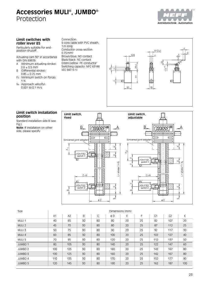
Limit switches withroller lever ESParticularly suitable for end-position shutoff.
Actuating cam 30° in accordancewith DIN 69639:A (Minimum actuating stroke):
2.6 ± 0.5 mmB (Differential stroke):
0.85 ± 0.25 mmFO (Minimum switch-on force):
1 NVe (Approach velocity):
0.001 to 0.1 m/s
Accessories MULI®, JUMBO®
Protection
Size Dimensions [mm]
A1 A2 B C ø D E F G1 G2 K
MULI 1 40 65 30 80 80 20 25 82 107 20
MULI 2 45 70 30 80 80 20 25 87 112 25
MULI 3 50 75 30 80 90 20 25 92 117 30
MULI 4 60 85 30 80 100 20 25 102 127 40
MULI 5 70 95 30 80 120 20 25 112 137 50
JUMBO 1 80 105 30 80 140 20 25 122 147 60
JUMBO 2 100 125 30 80 160 20 25 142 167 80
JUMBO 3 100 125 30 80 160 20 25 142 167 80
JUMBO 4 110 135 30 80 170 20 25 152 177 90
JUMBO 5 120 145 30 80 190 20 25 162 187 100
Connection:5-core cable with PVC sheath,1m longConductor cross-section0.75mm2
Brown/blue: NO contactBlack/black: NC contactGreen/yellow: PE conductorSwitching capacity: NFC 63146(IEC 947-5-1)
Limit switch installationpositionStandard installation side B (seeFig.).Note: If installation on otherside, please specify
Limit switch,adjustable
Limit switch,fixed
(Universal joint adapter) (Universal joint adapter)
switch 1
switch 2
switch 1
switch 2
L =
stro
ke 1
+ G
1
L =
stro
ke 1
+ G
2

Loading a wing for finalassembly at Airbus S.E.S.in Toulouse, France..

25
Motors and motor adapterflanges from NEFF comple-ment the MULI® and JUMBO®
worm gear screw jacks toproduce powerful drivepackages that can be put touse quickly and withoutcomplications. They areintended to have 3-phasemotors attached as standard.
Drive technology fromNEFF–Your benefit:
Optimum price-performanceratioSystem application, screw jackand drive all perfectly matched–everything from a single source.
Drive technologyWorm gear screw jacks and electric drive froma single source – what do you get out of it?
No hidden costsCalculation, planning, choice ofcomponents and parameteriza-tion are all handled by NEFF.
NoteThe offering presented here isthe standard program for theGerman market. As a rule, theinternational NEFF partners havea different range of motors andgears.
One contactFor all drive questions from cal-culation up to maintenance andservice you have one responsi-ble competent partner.
26
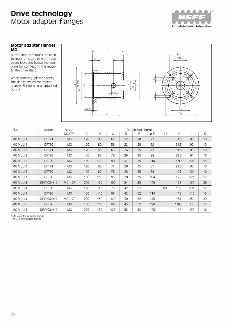
Motor adapter flangesMGMotor adapter flanges are usedto mount motors to worm gearscrew jacks and house the cou-pling for connecting the motorto the drive shaft.
When ordering, please specifythe side to which the motoradapter flange is to be attached(A or B)
Drive technologyMotor adapter flanges
Size Motor Design Dimensions [mm]MG/ZF1) A B C D E ø F F H I K
MG MULI 1 DFT71 MG 120 80 65 22 28 77 81.5 80 10
MG MULI 1 DFT80 MG 120 80 56 22 28 62 91.5 90 10
MG MULI 2 DFT71 MG 120 80 65 26 35 77 81.5 80 10
MG MULI 2 DFT80 MG 120 80 78 26 35 88 92.5 91 10
MG MULI 2 DFT90 MG 160 110 90 31 35 110 109.5 108 15
MG MULI 3 DFT71 MG 120 80 77 28 35 87 91.5 90 10
MG MULI 3 DFT80 MG 120 80 78 28 35 88 103 101 10
MG MULI 3 DFT90 MG 160 110 95 28 35 104 125 123 12
MG MULI 3 DFV100/112 MG + ZF 200 130 100 24 35 145 133 131 29
MG MULI 4 DFT80 MG 120 80 75 42 52 – 88 105 103 12
MG MULI 4 DFT90 MG 160 110 98 42 52 114 118 116 15
MG MULI 4 DFV100/112 MG + ZF 200 130 120 30 52 145 134 131 29
MG MULI 5 DFT90 MG 160 110 105 45 52 120 138.5 136 15
MG MULI 5 DFV100/112 MG 200 130 125 35 52 145 154 152 16
1) MG = Motor adapter flangeZF = Intermediate flange

27
Motor adapter flangesMGIntermediate flange ZF
Drive technologyMotor adapter flanges
1) When ordering, specify explicitly thediameter of the hole drilling in themotor side of the coupling half.
Dimensions [mm] Coupling Coupling half1) Coupling half1)
L M N R1 R2 S1 S2 T U Size MULI Motor
72 3.5 20 70.7 32 100 45.3 6.6 5.5 RA19 RA19 ø10 RA19 ø14
85 3.5 20 70.7 32 100 45.3 6.6 5.5 RA19 RA19 ø10 RA19 ø19
73 3.5 22 70.7 35 100 49.5 6.6 6.6 RA19 RA19 ø14 RA19 ø14
84 3.5 22 70.7 35 100 49.5 6.6 6.6 RA19 RA19 ø14 RA19 ø19
100 4 27 92 35 130 49.5 9 6.6 RA24 RA24 ø14 RA24 ø24
83 3.5 27 70.7 44 100 62.2 6.6 9 RA19 RA19 ø16 RA19 ø14
93 3.5 32 70.7 44 100 62.2 6.6 9 RA19 RA19 ø16 RA19 ø19
114 4 30 92 44 130 62.2 9 9 RA24 RA24 ø16 RA24 ø24
119 4.5 40 116.7 44 165 62.2 M10 9 RA28 RA28 ø16 RA28 ø28
94 3.5 35 70.7 55 100 78 6.6 11 RA24 RA24 ø20 RA24 ø19
106 4 30 92 55 130 78 M8 11 RA24 RA24 ø20 RA24 ø24
119 4.5 38 116.7 55 165 78 M10 11 RA28 RA28 ø20 RA28 ø28
122 4 48 92 60 130 85 M8 13.5 RA28 RA28 ø25 RA28 ø24
138 7 50 116.7 60 165 85 M10 13.5 RA28 RA28 ø25 RA28 ø28
Additionalflange forMULI3/MULI4C200

28
3-phase motors M3-phase 4-pole motors(1500rpm) in totally enclosedfan-cooled designs in accor-dance with VDE 0530 Part 1.Standard degree of protection:IP55. Temperature class F. OtherSEW motors on request.Notes: If the free shaft end ofthe motor is used as shaft for aslip-on emergency hand wheel,a device will be required witchinterrupts the power supplybefore the crank engages.Motors with different speedsand brake on request.
Drive technology3-phase motors
Performance data
Size Nominal Nominal Power Nominal Rel. locked- Nominal Rel. locked- Rel. Run- Rotor inertia Rotor inertia Brakingpower speed factor current at rotor cur- moment rotor torque up moment JMot JBremsmot moment[kW] [rpm] cos ϕ 400 V [A] rent IA/IN [Nm] MA/MN MH/MN [10-4kgm2] [10-4kgm2] [Nm]
DT71K4 0.15 1380 0.67 0.61 2.9 1.0 1.8 1.7 4.6 5.5 5.0
DT71C4 0.25 1380 0.70 0.80 2.8 1.7 1.8 1.7 4.6 5.5 5.0
DT71D4 0.37 1380 0.76 1.15 3.0 2.6 1.8 1.7 4.6 5.5 5.0
DT80K4 0.55 1360 0.72 1.75 3.4 3.9 2.1 1.8 7.5 7.5 10
DT80N4 0.75 1380 0.73 2.1 3.8 5.2 2.2 2.0 8.7 9.6 10
DT90S4 1.1 1400 0.77 2.8 4.3 7.5 2.0 1.9 25 31 20
DT90L4 1.5 1410 0.78 3.55 5.3 10.2 2.6 2.3 34 40 20
DV100M4 2.2 1410 0.83 4.7 5.9 15.0 2.7 2.3 53 59 40
DV100L4 3.0 1400 0.83 6.3 5.6 20.5 2.7 2.2 65 71 40
DV112M4 4.0 1420 0.84 8.7 5.4 26.9 2.4 2.1 98 110 55
a 1
f1
l11
l12 l1
l14 l13 u1
t 1
c1g1x9
i2
l2
k0
k
x
u
l
st
d
t d
y gb1
d1 s 1
p2
p
e 1
Flange shape
Foot shape
øs
n
k
x
b
f e
a
c
y
h
ød g
w2
g2
m1
w1
p2
x9

Drive technology3-phase motors
DimensionsThe values in brackets refer tomotors with brake.
Flange shape
Size Dimensions [mm]a1 b1 c1 d d1 e1 f1 g g1 i2 k k0 I I11
DFT71K4 120 80 8 14 11 100 3 145 122(127) 24 232 (296) 208 (296) 30 4
DFT71C4 120 80 8 14 11 100 3 145 122(127) 24 232 (296) 208 (272) 30 4
DFT71D4 120 80 8 14 11 100 3 145 122(127) 24 232 (296) 208 (272) 30 4
DFT80K4 120 80 8 19 14 100 3 145 122(127) 34 292 (356) 258 (322) 40 4
DFT80N4 120 80 8 19 14 100 3 145 122(127) 34 292 (356) 258 (322) 40 4
DFT90S4 160 110 10 24 19 130 3.5 197 154(161) 53.5 323 (408) 273 (358) 50 5
DFT90L4 160 110 10 24 19 130 3.5 197 154(161) 53.5 323 (408) 273 (358) 50 5
DFV100M4 200 130 10 28 19 165 3.5 197 166 60 371 (456) 311 (396) 60 5
DFV100L4 200 130 10 28 19 165 3.5 197 166 60 401 (486) 341 (426) 60 5
DFV112M4 200 130 11 28 24 165 3.5 221 179(182) 64 409 (489) 345 (425) 60 5
Foot shape
Size Dimensions [mm]a b c e f h m1 n s w1 w2
DT71K4 90 112 5 115 144 71 32 31 7 45 75
DT71C4 90 112 5 115 144 71 32 31 7 45 75
DT71D4 90 112 5 115 144 71 32 31 7 45 75
DT80K4 100 125 10 125 149 80 28 33 9 50 90
DT80N4 100 125 10 125 149 80 28 33 9 50 90
DT90S4 125 140 8 152 176 90 32 32 9 56 106
DT90L4 125 140 8 152 176 90 32 32 9 56 106
DV100M4 140 160 12 170 188 100 35 38 12 63 123
DV100L4 140 160 12 170 188 100 35 38 12 63 123
DV112M4 140 190 14 170 220 112 35 44 12 70 130
Size Dimensions [mm]I12 l1 l2 l13 l14 s1 t u t1 u1 x x9 y p2
DFT71K4 22 23 24 1 20 6.6 16 5 12.5 4 87 (127) 61 (86) 97 50
DFT71C4 22 23 24 1 20 6.6 16 5 12.5 4 87 (127) 61 (86) 97 50
DFT71D4 22 23 24 1 20 6.6 16 5 12.5 4 87 (127) 61 (86) 97 50
DFT80K4 32 30 31 4 22 6.6 21.5 6 16 5 87 (127) 61 (86) 97 50
DFT80N4 32 30 31 4 22 6.6 21.5 6 16 5 87 (127) 61 (86) 97 50
DFT90S4 40 40 42 4 32 9 27 8 21.5 6 87 (127) 76 (121) 97 50
DFT90L4 40 40 42 4 32 9 27 8 21.5 6 87 (127) 76 (121) 97 50
DFV100M4 50 40 42 4 32 11 31 8 21.5 6 106 (139) 74 (125) 109 56
DFV100L4 50 40 42 4 32 11 31 8 21.5 6 106 (139) 74 (125) 109 56
DFV112M4 50 50 55 5 40 11 31 8 27 8 106 (139) 91 (131) 109 56
29

30
Flexible couplings RA, RGFlexible couplings transmit thetorque by positive locking, andcompensate for slight non-alignment, stagger and offsetof shafts.Standard toothed ring 92 Shore A.
Drive technologyCouplings
Size Ver- max. Dimensions [mm] Offsets Locking Weightsion torque max. max. radial ∆ Kw [°] screw
axial- non-alignment max. angle staggerstagger n=1500 rpm at n=1500 rpm Dim. Dim.
[Nm] A1 E F B b D1 D d Cmin1) Cmax1) ∆ Ka [mm] ∆ Kr [mm] ∆ Kw [mm] G t [kg]
RA 14 1a 7.5 35 – 11 13 10 – 30 10 6 15 1.0 0.17 1.2 0.67 M4 5 0.05
RA 19 1 10 66 20 25 16 12 32 40 18 10 19 1.2 0.20 1.2 0.82 M5 10 0.15
RA 19 1a 10 66 – 25 16 12 – 41 18 19 24 1.2 0.20 1.2 0.82 M5 10 0.15
RA 24 1 35 78 24 30 18 14 40 55 27 14 24 1.4 0.22 0.9 0.85 M5 10 0.25
RA 24 1a 35 78 – 30 18 14 – 56 27 22 28 1.4 0.22 0.9 0.85 M5 10 0.35
RA 28 1 95 90 28 35 20 15 48 65 30 14 28 1.5 0.25 0.9 1.05 M6 15 0.40
RA 28 1a 95 90 – 35 20 15 – 67 30 28 38 1.5 0.25 0.9 1.05 M6 15 0.55
RG 38 1 190 114 37 45 24 18 66 80 38 16 38 1.8 0.28 1.0 1.35 M8 15 0.85
RG 42 1 265 126 40 50 26 20 75 95 46 28 42 2.0 0.32 1.0 1.70 M8 20 1.2
RG 48 1 310 140 45 56 28 21 85 105 51 28 48 2.1 0.36 1.1 2.00 M8 20 1.7
RG 55 1 410 160 52 65 30 22 98 120 60 30 55 2.2 0.38 1.1 2.30 M10 20 7.3
RG 65 1 625 185 61 75 35 26 115 135 68 40 65 2.6 0.42 1.2 2.70 M10 20 11.0
RG 75 1 975 210 69 85 40 30 135 160 80 40 75 3.0 0.48 1.2 3.30 M10 25 17.9
RG 90 1 2400 245 81 100 45 34 160 200 100 50 90 3.4 0.50 1.2 4.30 M12 30 28.5
1) This catalogue does not list allintermediate sizes. Further sizes on request.
OffsetsIn the case of the standard andlarge hubs RA 14–48, thetapped hole G for the lockingscrew is located opposite thegroove.Locking screws according toDIN916 with toothed washer.
Lmax. = L + ∆Ka
Axialverlagerung ∆Ka Radialverlagerung ∆Kr Winkelverlagerung ∆Kw [Grad]
∆KW [mm] = Lmax – Lmin
Version 1 Version 1a
Axial offset ∆ Ka Radial offset ∆ Kr Angular offset ∆ Kw [Grad]

31
Handwheels HR 2-spoke handwheel of chill-castlight aluminium RN 9501, polis-hed, with rotating conical handleof black plastic. Bore keyed toDIN 6885.
Drive technologyHandwheels
Size Dimensions [mm] BoreA D d d1 d2 H7 L1 L l1 l2
HR 80 10 80 31 21 ø10 16 29 50 2.5
HR 80 10 80 31 21 ø14 16 29 50 2.5
HR 100 10 100 33 21 ø10 17 33 50 2.5
HR 100 10 100 33 21 ø14 17 33 50 2.5
HR 125 13 125 35 22 ø10 18 36 56 2.5
HR 125 13 125 35 22 ø14 18 36 56 2.5
HR 140 13 140 37 22 ø14 19 39 56 2.5
HR 140 13 140 37 22 ø16 19 39 56 2.5
HR 160 16 160 40 23 ø14 20 40 65 2.5
HR 160 16 160 40 23 ø16 20 40 65 2.5
HR 200 16 200 45 26 ø16 24 45 80 2.5
HR 200 16 200 45 26 ø20 24 45 80 2.5
HR 250 19 250 52 31 ø20 28 50 102 2.5
HR 250 19 250 52 31 ø25 28 50 102 2.5

32
Pillow block UKP The standard range for housingbearings with clamping sleeve.Cast iron housing with surfacepainted for protection fromcorrosion. The bearing insets inrolled steel have forged rings,which prolong the lifetime ofthe bearings.
Drive technologyPillow blocks
Size Shaft Size Dimensions [mm] Dynamic Static Weightdiam- GX- Load Loadeter shaft rating rating[mm] L H A1 A J N N1 L1 H1 H2 s1 B D2 G [kN] [kN] [kg]
UKP205H 20 140 36.5 26 38 105 13 19 42 16 70 18.5 35 38 M6x1 14.0 7.88 0.8
UKP206H 25 165 42.9 30 48 121 17 21 54 18 83 20.5 38 45 M6x1 19.5 11.2 1.4
UKP207H 30 1 167 47.6 31 48 127 17 21 54 19 94 22.5 43 52 M6x1 25.7 15.2 1.8
UKP208H 35 184 49.2 34 54 137 17 23 52 19 100 24.5 46 58 M6x1 29.6 18.2 2.2
UKP209H 40 2 190 54.0 37 54 146 17 23 60 20 108 26 50 65 M6x1 31.85 20.8 2.5
UKP210H 45 4 206 57.2 39 60 159 20 25 65 22 114 27.5 55 70 M6x1 35.1 23.2 3.1
UKP211H 50 219 63.5 40 60 171 20 25 70 22 126 29 59 75 M6x1 43.55 29.2 3.7
UKP212H 55 241 69.8 44 70 184 20 25 70 25 138 31 62 80 M6x1 52.5 32.8 5.0
UKP213H 60 8 265 76.2 46 70 203 25 29 77 27 150 32 65 85 M6x1 57.2 40.0 6.1
33
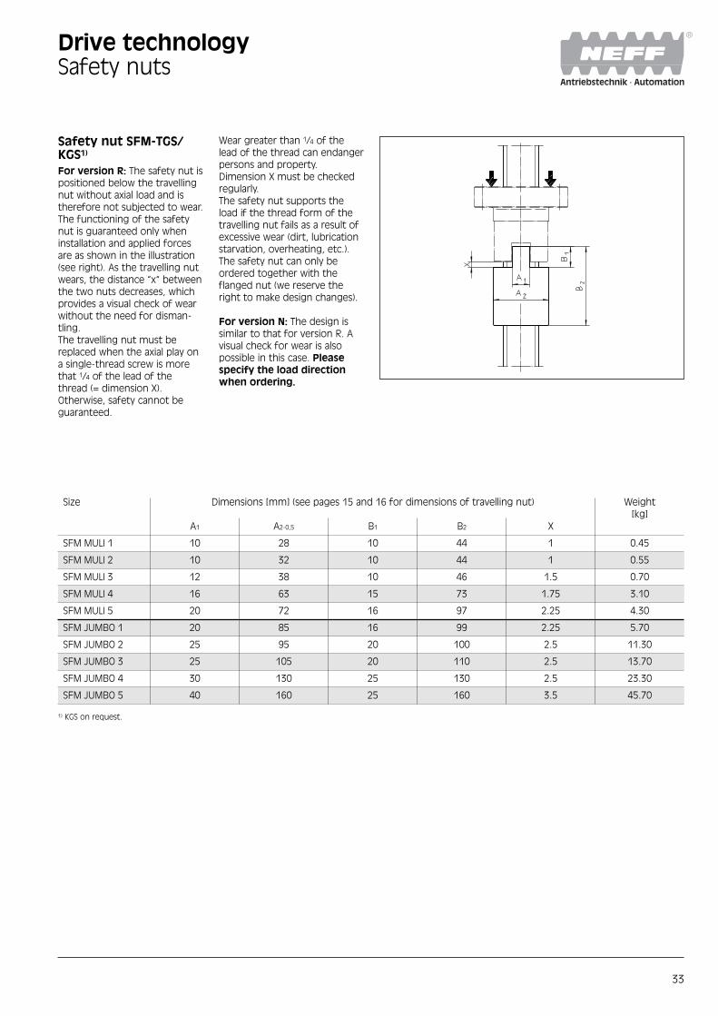
Safety nut SFM-TGS/KGS1)
For version R: The safety nut ispositioned below the travellingnut without axial load and istherefore not subjected to wear.The functioning of the safetynut is guaranteed only wheninstallation and applied forcesare as shown in the illustration(see right). As the travelling nutwears, the distance “x“ betweenthe two nuts decreases, whichprovides a visual check of wearwithout the need for disman-tling.The travelling nut must bereplaced when the axial play ona single-thread screw is morethat 1/4 of the lead of thethread (= dimension X).Otherwise, safety cannot beguaranteed.
Wear greater than 1/4 of thelead of the thread can endangerpersons and property.Dimension X must be checkedregularly.The safety nut supports theload if the thread form of thetravelling nut fails as a result ofexcessive wear (dirt, lubricationstarvation, overheating, etc.).The safety nut can only beordered together with theflanged nut (we reserve theright to make design changes).
For version N: The design issimilar to that for version R. Avisual check for wear is alsopossible in this case. Pleasespecify the load directionwhen ordering.
Size Dimensions [mm] (see pages 15 and 16 for dimensions of travelling nut) Weight[kg]
A1 A2-0,5 B1 B2 X
SFM MULI 1 10 28 10 44 1 0.45
SFM MULI 2 10 32 10 44 1 0.55
SFM MULI 3 12 38 10 46 1.5 0.70
SFM MULI 4 16 63 15 73 1.75 3.10
SFM MULI 5 20 72 16 97 2.25 4.30
SFM JUMBO 1 20 85 16 99 2.25 5.70
SFM JUMBO 2 25 95 20 100 2.5 11.30
SFM JUMBO 3 25 105 20 110 2.5 13.70
SFM JUMBO 4 30 130 25 130 2.5 23.30
SFM JUMBO 5 40 160 25 160 3.5 45.70
Drive technologySafety nuts
1) KGS on request.

34
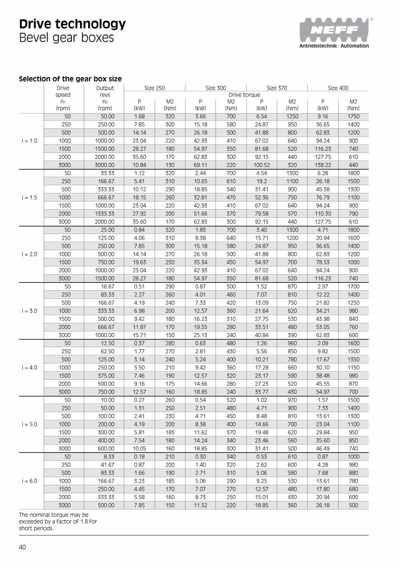
Drive technologyBevel gear boxes
Bevel gear boxes KRGThe spiral bevel gear boxesoffer numerous advantagesto the designer and havebeen specially selected tocomplement the NEFF rangeof worm gear screw jacksand accessories. A total ofeight box sizes and accesso-ries are available as standard.The gear boxes are fullymachined with tapped holesfor universal mounting, thusoffering six possible mount-ing positions.
Housing and Flange:Version: CubeMaterial: Lamellar graphite cast
iron EN-GJL-250 (0.6025) orspheroidal graphite cast ironENGJS- 400-15 (0.7040) or G-AlSi 10 Mg (0.1645)
Shaft:Version: Shaft centring accord-
ing to DIN 332 Sheet 2, feath-er key according to DIN 6885,Sheet 1
Tolerance: j6 or k6Material: C45 (1.0503) or
42 CrMo 4 (1.7225)
Hollow shafts:Version: With keyway or smooth,
with shrink-fit washerTolerance: Hole H7Material: C 45 (1.0503)
Bevel gears:Version: Klingelnberg Palloid or
Klingelnberg Zyklo-Palloid spi-ral teeth, optimised toothflanks and profile geometry,tooth flanks milled, hardenedand lapped
Material: Stainless steel 16 MnCr 5 (1.7131) or 17 Cr NiMo 6 (1.6587)
Shaft-hub connection:Version: Non-positive or positive
locking, parts are fitted warm
Shaft seal:Version: With or without dust
scraper according to DIN 3760Material: NBR or Viton
Bearings:Version: Conical roller bearings
or roller bearings, dependingon version
Lubricants:Version: According to DIN51502
mineral grease or oil,depending on revs.
Installation position: Please specify when ordering.
Volume: Depends on installationposition, see OperatingInstructions.
Surface treatment:Version: Nitro-cellulose base
coatColour: RAL 7035 light grey
Noise:Approx. 75 dB(A) at 1m distance
Lifetime of bearings:Approx. 20,000 operating hours
Max. permitted geartemperature:80° C
Mechanical Gear sizeefficiency η 50 100–230 250–400
At nominal moment 0.85 ≤ η ≤ 0.9 0.9 ≤ η ≤ 0.94 0.95 ≤ η ≤ 0.96
Type L
Ba 30 Ba 40 Ba 50 Ba 60
Type ML
Ba 30 Ba 40 Ba 50 Ba 60

35
Dimensions [mm]Type L 50
Drive technologyBevel gear boxes
Size Gear ratio D1 D2 D3 D7 D11 D12 D13 D21 D22 D23 D31 D32 D33
1 – 250 12j6 12j6 12j6 M6 44f7 64,5 54 44f7 64.5 54 44f7 64.5 54
3 + 4
Size Gear ratio L30 L32 L34 L71 R Feather key D1 Feather key D2 + D3
1 – 250 72 42 2 45 0.8 4 x 4 x 20 4 x 4 x 20
3 + 4
Size Gear ratio L L1 L2 L3 L7 L10 L12 L14 L20 L22 L24
1 – 2 10050 144 26 26 26 65 42 2 72 42 2
3 + 4 115

36
Size Gear ratio D1 D2 D3 D7 D8 D11 D12 D13 D21 D31 L L1 L2 L3
1 – 2 18j6 35
100 3 + 4 15j6 18j6 18j6 M8 9 60f7 89f7 75 60f7 60f7 190 30 35 35
5 + 6 12j6 25
1 – 2 25j6 45
200 3 + 4 20j6 25j6 25j6 M10 11 80f7 119f7 100 80f7 80f7 244 40 45 45
5 + 6 15j6 30
Size Gear ratio L7 L10 L12 L14 L20 L22 L24 L30 L32 L34 L71 R Feather key D1 Feather key D2 + D3
1 – 2 122 6 x 6 x 25
100 3 + 4 90 127 55 2 95 55 2 95 55 2 70 1 5 x 5 x 20 6 x 6 x 25
5 + 6 122 4 x 4 x 16
1 – 2 162 8 x 7 x 36
200 3 + 4 120 157 75 2 122 72 3 122 72 3 100 1 6 x 6 x 30 8 x 7 x 36
5 + 6 147 5 x 5 x 20
Drive technologyBevel gear boxes
Dimensions [mm]Type L 100 – 200

37
Size Gear ratio D1 D2 D3 D7 D8 D11 D12 D13 D21 D31 L L1 L2 L3
1 – 2 32j6
230 3 + 4 28j6 32j6 32j6 M10 11 95f7 135f7 115 100f7 100f7 274 50 50 50
5 + 6 24j6
1 – 2 35j6 60
250 3 + 4 28j6 35j6 35j6 M12 13.5 110f7 158f7 135 110f7 110f7 320 55 60 60
5 + 6 24j6 50
1 – 2 42j6 80
300 3 + 4 35j6 42j6 42j6 M12 13.5 120f7 198f7 175 120f7 120f7 406 68 80 80
5 + 6 28j6 55
1 – 2 55j6 150f7 90
370 3 + 4 40j6 55j6 55j6 M16 17.5 225f7 200 150f7 150f7 454 80 90 90140f7
5 + 6 35j6 70
1 – 2 60j6 110
400 3 + 4 50j6 60j6 60j6 M16 17.5 160f7 258f7 230 180f7 180f7 570 110 11090
5 + 6 45j6
Drive technologyBevel gear boxes
Dimensions [mm]Type L 230 – 400
Size Gear ratio L7 L10 L12 L14 L20 L22 L24 L30 L32 L34 L71 R Feather key D1 Feather key D2 + D3
1 – 2 180 10 x 8 x 45
230 3 + 4 140 83 2 137 82 3 137 82 3 110 2 8 x 7 x 40 10 x 8 x 45195
5 + 6 8 x 7 x 40
1 – 2 212 10 x 8 x 45
250 3 + 4 160 227 95 2 160 95 3 160 95 3 120 2 8 x 7 x 40 10 x 8 x 45
5 + 6 222 8 x 7 x 40
1 – 2 273 3 12 x 8 x 60
300 3 + 4 200 261 120 203 117 3 203 117 3 160 3 10 x 8 x 45 12 x 8 x 602
5 + 6 248 8 x 7 x 45
1 – 2 305 16 x 10 x 80
370 3 + 4 230 310 135 2 227 132 3 227 132 3 180 5 12 x 8 x 60 16 x 10 x 80
5 + 6 300 10 x 8 x 50
1 – 2 380 5 18 x 11 x 90
400 3 + 4 260 150 5 285 150 20 285 150 20 220 14 x 9 x 70 18 x 11 x 90360 10
5 + 6 14 x 9 x 70

38
Drive technologyBevel gear boxes
Dimensions [mm]Type ML 50/100/200
Size Gear ratio d G7 b1 e1 a1 a2 s2 l1
9 70 85 75 100 4 x ø7 23
50 1 – 4 11 80 100 90 120 4 x ø7 26
14 95 115 115 140 4 x ø9 33
9 70 85 95 105 4 x ø7 23
11 80 100 95 120 4 x ø7 26100 1 – 6
14 95 115 115 140 4 x ø9 35
19 110 130 140 160 4 x ø9 45
11 80 100 125 140 4 x ø7 26
14 95 115 125 140 4 x ø9 35
200 1 – 6 19 110 130 140 160 4 x ø9 45
24 110 130 140 160 4 x ø9 55
28 130 165 140 190 4 x ø11 65
Size Gear ratio f1 c1 D16 L15 L16 L17
50 1 – 4 4.5 16 8.5 90 9.5 10
100 1 – 6 5 22 10 125 13 12.5
200 1 – 6 5 25 14 145 15 16.5

39
Drive technologyBevel gear boxes
Selection of the gear box sizeDrive Output Size 50 Size 100 Size 200 Size 230speed revs Drive torque
n1 n2 P M2 P M2 P M2 P M2[rpm] [rpm] [kW] [Nm] [kW] [Nm] [kW] [Nm] [kW] [Nm]
50 50.00 0.09 18 0.26 50 0.68 130 1.05 200
250 1000.00 0.47 18 1.28 49 3.14 120 4.71 180
500 500.00 0.89 17 2.41 46 5.76 110 8.90 170
i = 1.0 1000 1000.00 1.68 16 4.40 42 9.42 90 15.71 150
1500 1500.00 2.20 14 5.81 37 12.88 82 20.42 130
2000 2000.00 2.51 12 6.91 33 12.29 73 25.13 120
3000 3000.00 3.14 10 8.80 28 18.85 60 28.27 90
50 33.33 0.06 18 0.17 50 0.45 130 0.70 200
250 166.67 0.31 18 0.86 49 2.09 120 3.32 190
500 333.33 0.59 17 1.68 48 3.84 110 6.28 180
i = 1.5 1000 666.67 1.12 16 3.07 44 6.98 100 11.17 160
1500 1000.00 1.57 15 4.19 40 9.42 90 15.71 150
2000 1333.33 1.95 14 5.31 38 11.87 85 19.55 140
3000 2000.00 2.51 12 6.91 33 15.29 73 25.13 120
50 25.00 0.05 18 0.13 50 0.34 130 0.52 200
250 125.00 0.24 18 0.64 49 1.64 125 2.49 190
500 250.00 0.47 18 1.26 48 3.14 120 4.71 180
i = 2.0 1000 500.00 0.89 17 2.36 45 5.76 110 8.90 170
1500 750.00 1.26 16 3.38 43 7.85 100 12.57 160
2000 1000.00 1.57 15 4.19 40 9.42 90 15.71 150
3000 1500.00 2.20 14 5.81 37 12.88 82 20.42 130
50 16.67 0.03 16 0.07 40 0.17 95 0.31 175
250 83.33 0.13 15 0.34 39 0.77 88 1.48 170
500 166.67 0.26 15 0.66 38 1.47 84 2.79 160
i = 3.0 1000 333.33 0.49 14 1.29 37 2.62 75 5.24 150
1500 500.00 0.68 13 1.83 35 3.51 67 6.81 130
2000 666.67 0.84 12 2.23 32 4.54 65 8.38 120
3000 1000.00 1.15 11 2.93 28 5.45 52 10.47 100
50 12.50 0.02 15 0.05 38 0.12 95 0.23 175
250 62.50 0.10 15 0.25 38 0.60 92 1.11 170
500 125.00 0.18 14 0.48 37 1.15 88 2.16 165
i = 4.0 1000 250.00 0.34 13 0.92 35 2.09 80 3.93 150
1500 375.00 0.51 13 1.34 34 2.91 74 5.50 140
2000 500.00 0.63 12 1.62 31 3.56 68 6.81 130
3000 750.00 0.86 11 2.28 29 4.71 60 7.85 100
50 10.00 0.04 38 0.10 95 0.18 175
250 50.00 0.19 37 0.48 92 0.89 170
500 100.00 0.37 35 0.92 88 1.68 160
i = 5.0 1000 200.00 0.69 33 1.68 80 2.93 140
1500 300.00 0.94 30 2.29 73 3.77 120
2000 400.00 1.17 28 2.85 68 4.61 110
3000 600.00 1.70 27 3.77 60 6.28 100
50 8.33 0.03 32 0.06 74 0.14 160
250 41.67 0.14 31 0.31 70 0.65 150
500 83.33 0.26 30 0.60 69 1.22 140
i = 6.0 1000 166.67 0.51 29 1.19 68 2.27 130
1500 250.00 0.73 28 1.68 64 3.14 120
2000 333.33 0.94 27 2.09 60 3.84 110
3000 500.00 1.36 26 2.72 52 4.97 95
The nominal torque may beexceeded by a factor of 1.8 forshort periods.
40
Drive technologyBevel gear boxes
Selection of the gear box sizeDrive Output Size 250 Size 300 Size 370 Size 400speed revs Drive torque
n1 n2 P M2 P M2 P M2 P M2[rpm] [rpm] [kW] [Nm] [kW] [Nm] [kW] [Nm] [kW] [Nm]
50 50.00 1.68 320 3.66 700 6.54 1250 9.16 1750
250 250.00 7.85 300 15.18 580 24.87 950 36.65 1400
500 500.00 14.14 270 26.18 500 41.88 800 62.83 1200
i = 1.0 1000 1000.00 23.04 220 42.93 410 67.02 640 94.24 900
1500 1500.00 28.27 180 54.97 350 81.68 520 116.23 740
2000 2000.00 35.60 170 62.83 300 92.15 440 127.75 610
3000 3000.00 10.84 130 69.11 220 100.52 320 138.22 440
50 33.33 1.12 320 2.44 700 4.54 1300 6.28 1800
250 166.67 5.41 310 10.65 610 19.2 1100 26.18 1500
500 333.33 10.12 290 18.85 540 31.41 900 45.38 1300
i = 1.5 1000 666.67 18.15 260 32.81 470 52.36 750 76.79 1100
1500 1000.00 23.04 220 42.93 410 67.02 640 94.24 900
2000 1333.33 27.92 200 51.66 370 79.58 570 110.30 790
3000 2000.00 35.60 170 62.83 300 92.15 440 127.75 610
50 25.00 0.84 320 1.83 700 3.40 1300 4.71 1800
250 125.00 4.06 310 8.38 640 15.71 1200 20.94 1600
500 250.00 7.85 300 15.18 580 24.87 950 36.65 1400
i = 2.0 1000 500.00 14.14 270 26.18 500 41.88 800 62.83 1200
1500 750.00 19.63 250 35.34 450 54.97 700 78.53 1000
2000 1000.00 23.04 220 42.93 410 67.02 640 94.24 900
3000 1500.00 28.27 180 54.97 350 81.68 520 116.23 740
50 16.67 0.51 290 0.87 500 1.52 870 2.97 1700
250 83.33 2.27 260 4.01 460 7.07 810 12.22 1400
500 166.67 4.19 240 7.33 420 13.09 750 21.82 1250
i = 3.0 1000 333.33 6.98 200 12.57 360 21.64 620 34.21 980
1500 500.00 9.42 180 16.23 310 27.75 530 43.98 840
2000 666.67 11.87 170 19.55 280 33.51 480 53.05 760
3000 1000.00 15.71 150 25.13 240 40.84 390 62.83 600
50 12.50 0.37 280 0.63 480 1.26 960 2.09 1600
250 62.50 1.77 270 2.81 430 5.56 850 9.82 1500
500 125.00 3.14 240 5.24 400 10.21 780 17.67 1350
i = 4.0 1000 250.00 5.50 210 9.42 360 17.28 660 30.10 1150
1500 375.00 7.46 190 12.57 320 23.17 590 38.48 980
2000 500.00 9.16 175 14.66 280 27.23 520 45.55 870
3000 750.00 12.57 160 18.85 240 33.77 430 54.97 700
50 10.00 0.27 260 0.54 520 1.02 970 1.57 1500
250 50.00 1.31 250 2.51 480 4.71 900 7.33 1400
500 100.00 2.41 230 4.71 450 8.48 810 13.61 1300
i = 5.0 1000 200.00 4.19 200 8.38 400 14.66 700 23.04 1100
1500 300.00 5.81 185 11.62 370 19.48 620 29.84 950
2000 400.00 7.54 180 14.24 340 23.46 560 35.60 850
3000 600.00 10.05 160 18.85 300 31.41 500 46.49 740
50 8.33 0.18 210 0.30 340 0.53 610 0.87 1000
250 41.67 0.87 200 1.40 320 2.62 600 4.28 980
500 83.33 1.66 190 2.71 310 5.06 580 7.68 880
i = 6.0 1000 166.67 3.23 185 5.06 290 9.25 530 13.61 780
1500 250.00 4.45 170 7.07 270 12.57 480 17.80 680
2000 333.33 5.58 160 8.73 250 15.01 430 20.94 600
3000 500.00 7.85 150 11.52 220 18.85 360 26.18 500
The nominal torque may beexceeded by a factor of 1.8 forshort periods.

41
Universal joint shaftsGXUniversal joint shafts are usedto connect several worm gearscrew jacks together. The shaftsattenuate noise, vibrations andimpacts and compensate foraxial, radial and angular errors.They offer exceptional torsionalrigidity, high temperature andoil resistance and are particular-ly suitable where long lengthsand/or high speeds are a factor.Elastic universal joint shafts aremaintenance-free; the centralsection can be removed radially(to the side) without axial dis-placement of the connectedunits.
They are supplied as a length oftube (dimension L to be speci-fied by customer) fitted withcoupling assemblies at bothends. Pillow blocks are generallynot required, except for verylong connections.For optimum alignment of thejack gear screws, we recom-mend the use of universal-jointed shafts with clampingsets.
Drive technologyUniversal joint shafts
Size Dimensions [mm] WeightM1) m12) m23)
[Nm] A B d2 min d2 max d3 d4 L2 N2 R [kg] [kg/m]
GX 1 10 24 7 10 25 56 56 24 36 30 0.47 1.05
GX 2 30 24 8 14 38 85 88 28 55 40 1.06 1.42
GX 4 60 28 8 16 45 100 100 30 65 45 2.31 1.61
GX 8 120 32 10 20 55 120 125 42 80 60 3.55 2.16
GX 16 240 42 12 22 70 150 155 50 100 70 6.16 2.53
GX 25 370 46 14 22 85 170 175 55 115 85 9.5 3.09
GX 30 550 58 16 28 100 200 205 66 140 100 15.21 3.64
Universal joint shaftdiagramas a function of length andspeed.
1) Transmittable torque 2) m1 = Weight without central section 3) m2 = Weight of central section permetre
Spee
d n
Universal joint shaft size[rpm]
Length of centre section L

42
Drive technologyLength of the universal joint shaft for MULI® with tensioner
MULI® 1with DKWN tensioner (10–20)Starting torque of thetensioning element 1.2 Nm
MULI® 2with DKWN tensioner (14–26)Starting torque of thetensioning element 2.1 Nm
MULI® 3with DKWN tensioner (16–32)Starting torque of thetensioning element 4.9 Nm
MULI® 4with DKWN tensioner (20–38)Starting torque of thetensioning element 9.7 Nm
MULI® 5with DKWN tensioner (25–47)Starting torque of thetensioning element 16.5 Nm
Center distance A
Length of joint shaft L
Center distance A
Length of joint shaft L
Center distance A
Length of joint shaft L
Center distance A
Length of joint shaft L
Center distance A
Length of joint shaft L

43
Connecting shaftdiagramas a function of length andspeed.
Drive technologyConnecting shafts
Connecting shafts VWThe Series VW connectingshafts are rigid shafts with a key way at each end. Forgreater distances and diametersof axle, some of these shaftsare available as tubular shafts. The holes in the couplings mustbe drilled to fit the diameter ofthe shaft.(Torques see chart “couplings”on page 30.)
Size Dimensions [mm]
D C B T
VW 20 20 30 6 3.5
VW 25 25 35 8 4
VW 30 30 40 8 4
VW 35 35 40 10 5
VW 40 40 50 12 5
VW 45 45 50 14 5.5
VW 50 50 70 14 5.5
Connecting shaft size
Spee
d n
Length of centre section L
[rpm]
44
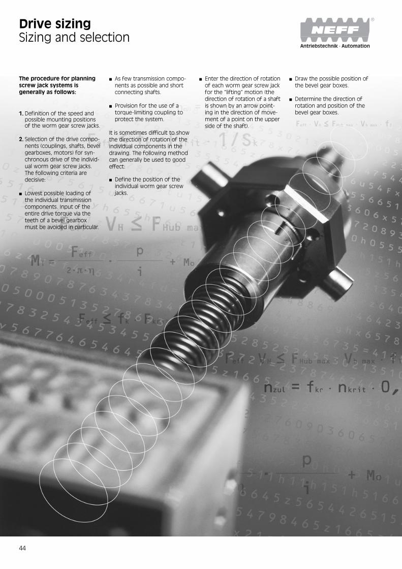
The procedure for planningscrew jack systems isgenerally as follows:
1. Definition of the speed andpossible mounting positionsof the worm gear screw jacks.
2. Selection of the drive compo-nents (couplings, shafts, bevelgearboxes, motors) for syn-chronous drive of the individ-ual worm gear screw jacks.The following criteria aredecisive:
■ Lowest possible loading ofthe individual transmissioncomponents. Input of theentire drive torque via theteeth of a bevel gearboxmust be avoided in particular.
■ As few transmission compo-nents as possible and shortconnecting shafts.
■ Provision for the use of atorque-limiting coupling toprotect the system.
It is sometimes difficult to showthe direction of rotation of theindividual components in thedrawing. The following methodcan generally be used to goodeffect:
■ Define the position of theindividual worm gear screwjacks.
Drive sizingSizing and selection
■ Enter the direction of rotationof each worm gear screw jackfor the “lifting“ motion (thedirection of rotation of a shaftis shown by an arrow point-ing in the direction of move-ment of a point on the upperside of the shaft).
■ Draw the possible position ofthe bevel gear boxes.
■ Determine the direction ofrotation and position of thebevel gear boxes.

45
Drive sizingExamples for the direction of rotation
Fig. 1Illustration of direction ofrotation
Fig. 2Direction of rotation of a wormgear screw jack (N) for “lifting“motion, top view.
Fig. 3Jack system with four wormgear screw jacks and two bevelgear boxes
Fig. 4Jack system, variant 1:Different position of drivemotor, but only ratio 1:1possible.
Fig. 5Jack system, variant 2:Very economical.
Worm gear screw jack Bevel gear box
Universal joint shaft Coupling
lifting
lifting
Fig. 3
Fig. 4 Fig. 5
Fig. 1 Fig. 2

46
Feff = Axial force acting on thejack screw
FS = Result of all lateral forcesacting on the jack screw
M = Torque of the jack screwor nut (not applicable inthe case of version V)
VH = Lifting speedFax = Axial force acting on drive
shaftFr = Radial force acting on
drive shaftMT = Drive torquenT = Drive speed
Selection of a wormgear screw jack andcorresponding driveunitAfter selecting the drive unit, itis important to check whetherthe worm gear screw jack orany transmission componentsmay be overloaded by the driveunit (see page 47).The following points should alsobe established:1. On which side is the motor to
be mounted2. Direction of rotation of the
jack systems.
Forces and torquevalues acting on theworm gear screw jackNote:Forces and torque values canonly be estimated by makingsimplified assumptions. Thecoefficients of friction of slidingpairs, and thus the heat whichthese generate, and the resul-tant service lifetime depend onload, speed, temperature andlubrication conditions. Criticalspeeds and buckling lengthsdepend on the rigidity andmass of the clamping systemsand machine frames, etc.
Drive sizing
Hubspindel
Antriebswelle(Schneckenwelle)
Jack screw
Drive shaft(worm shaft)
47
Drive sizing
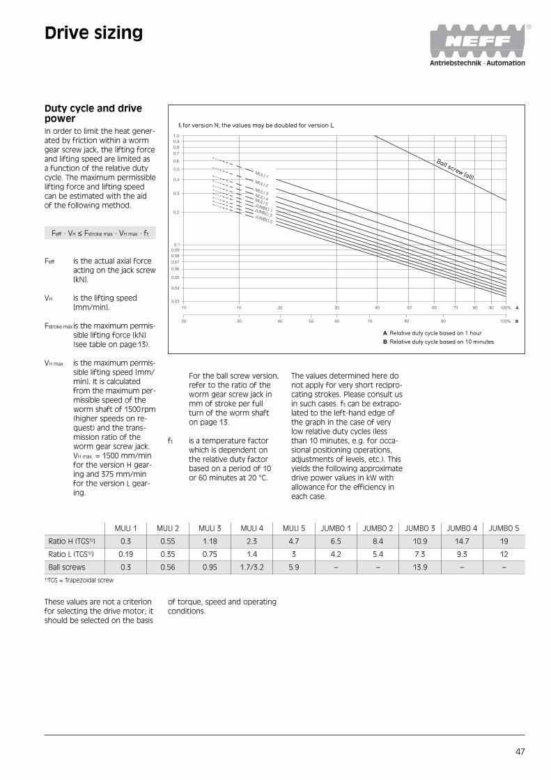
The values determined here donot apply for very short recipro-cating strokes. Please consult usin such cases. ft can be extrapo-lated to the left-hand edge ofthe graph in the case of verylow relative duty cycles (lessthan 10 minutes, e.g. for occa-sional positioning operations,adjustments of levels, etc.). Thisyields the following approximatedrive power values in kW withallowance for the efficiency ineach case.
Duty cycle and drivepowerIn order to limit the heat gener-ated by friction within a wormgear screw jack, the lifting forceand lifting speed are limited asa function of the relative dutycycle. The maximum permissiblelifting force and lifting speedcan be estimated with the aidof the following method.
Feff · VH ≤ Fstroke max · VH max · ft
Feff is the actual axial forceacting on the jack screw[kN].
VH is the lifting speed[mm/min].
Fstroke max is the maximum permis-sible lifting force [kN](see table on page13).
VH max is the maximum permis-sible lifting speed [mm/min]. It is calculatedfrom the maximum per-missible speed of theworm shaft of 1500rpm(higher speeds on re-quest) and the trans-mission ratio of theworm gear screw jack.VH max. = 1500 mm/minfor the version H gear-ing and 375 mm/minfor the version L gear-ing.
For the ball screw version,refer to the ratio of theworm gear screw jack inmm of stroke per fullturn of the worm shafton page 13.
ft is a temperature factorwhich is dependent onthe relative duty factorbased on a period of 10or 60 minutes at 20 °C.
MULI 1 MULI 2 MULI 3 MULI 4 MULI 5 JUMBO 1 JUMBO 2 JUMBO 3 JUMBO 4 JUMBO 5
Ratio H (TGS1)) 0.3 0.55 1.18 2.3 4.7 6.5 8.4 10.9 14.7 19
Ratio L (TGS1)) 0.19 0.35 0.75 1.4 3 4.2 5.4 7.3 9.3 12
Ball screws 0.3 0.56 0.95 1.7/3.2 5.9 – – 13.9 – –
These values are not a criterionfor selecting the drive motor; itshould be selected on the basis
of torque, speed and operatingconditions.
0,90,8
ft für Ausführung H: für Ausführung L können die doppelten Werte angenommen werden
0,7
0,6
0,5
0,4
0,3
0,2
0,10,090,080,07
0,06
0,05
0,04
0,03
10
20
15 20
30 40
30
50 60
40 50
70 80
60
90
70 80 90 100%
100%
A
B
A: Relative Einschaltdauer bezogen auf 1 h
B: Relative Einschaltdauer bezogen auf 10 min
MULI 1MULI 2MULI 3MULI 4MULI 5JUMBO 1JUMBO 3JUMBO 5
KGT (alle)
1,0
ft for version N; the values may be doubled for version L
Ball screw (all)
A: Relative duty cycle based on 1 hour
B: Relative duty cycle based on 10 minutes
1)TGS = Trapezoidal screw
48
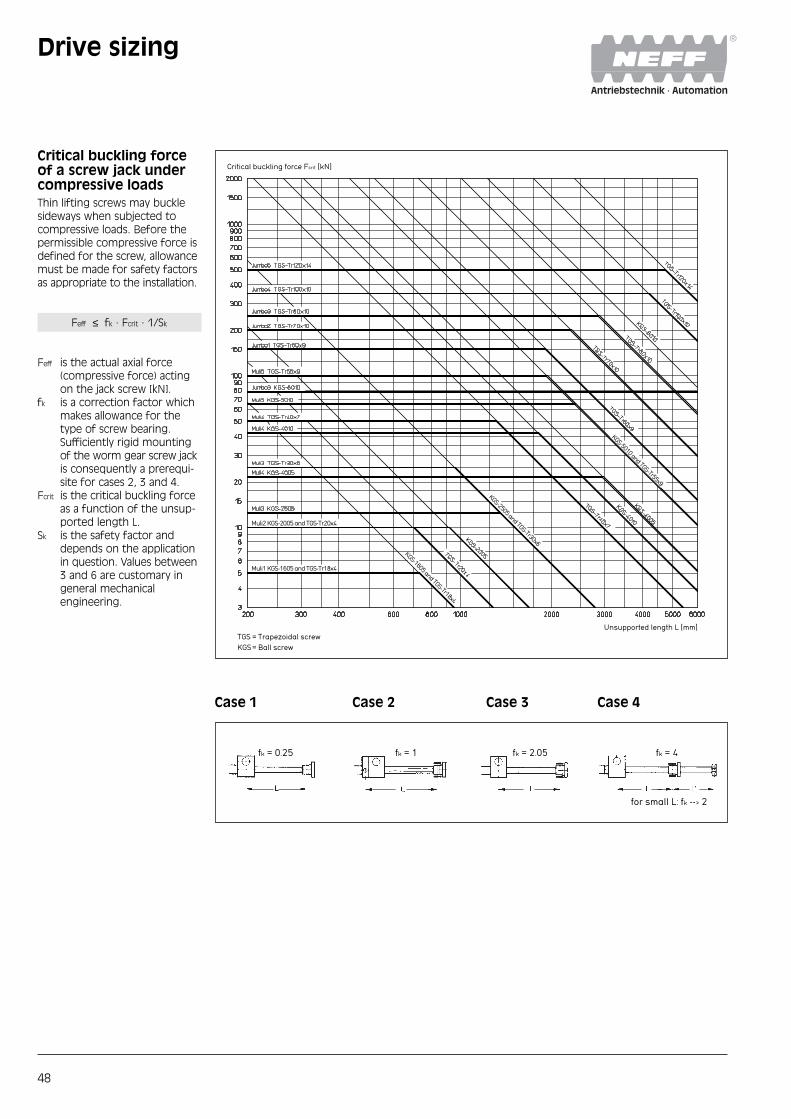
Critical buckling forceof a screw jack undercompressive loadsThin lifting screws may bucklesideways when subjected tocompressive loads. Before thepermissible compressive force isdefined for the screw, allowancemust be made for safety factorsas appropriate to the installation.
Feff ≤ fk · Fcrit · 1/Sk
Feff is the actual axial force(compressive force) actingon the jack screw [kN].
fk is a correction factor whichmakes allowance for thetype of screw bearing.Sufficiently rigid mountingof the worm gear screw jackis consequently a prerequi-site for cases 2, 3 and 4.
Fcrit is the critical buckling forceas a function of the unsup-ported length L.
Sk is the safety factor anddepends on the applicationin question. Values between3 and 6 are customary ingeneral mechanicalengineering.
Drive sizing
Case 1 Case 2 Case 3 Case 4
fk = 2,05
für kleine L gilt: fk --› 2
fk = 4fk = 1fk = 0,25
Critical buckling force Fcrit [kN]
Unsupported length L [mm]TGS = Trapezoidal screwKGS= Ball screw
Muli2 KGS-2005 and TGS-Tr20x4
Muli1 KGS-1605 and TGS-Tr18x4
KGS-1605 and TGS-Tr18x4
KGS-2505 and TGS-Tr30x6
KGS-5010 and TGS-Tr55x9
fk = 0.25 fk = 1 fk = 2.05 fk = 4
for small L: fk --> 2

49
Critical speed of jackscrews(Version R only)Resonant bending vibration maydevelop with thin screws rotat-ing at high speed. Assuming asufficiently rigid assembly, theresonant frequency can be esti-mated with the aid of the fol-lowing method.
nperm = fkr · ncrit · 0.8
nperm is the maximum permissi-ble screw speed [rpm].
fkr is a correction factor whichmakes allowance for thetype of screw bearing.Sufficiently rigid mountingof the worm gear screwjack and bearing is conse-quently a prerequisite forcases 2, 3 and 4.
ncrit is the critical screw speed;it corresponds to the basicbending vibration of thescrew and leads to reso-nance effects.
Worm gear screw jacks withmulti-start screws are also avail-able for applications with highlifting speeds. These versionsrun at a considerably lower screwspeed and better efficiency forthe same lifting speed. They aregenerally not self-locking.
Drive sizing
Case 1 Case 2 Case 3 Case 4
fkr = 0,36 fk = 1 fkr = 2,23fkr = 1,47
Theoretical critical speed ncrit [rpm]
Unsupported length L [mm]
Speed limit
TGS = Trapezoidal screwKGS= Ball screw
fkr = 0.36 fkr = 1 fkr = 1.47 fkr = 2.23

50
Required drive torqueof a worm gear screwjackThe required drive torque of aworm gear screw jack is gov-erned by the axial load actingon the jack screw, the transmis-sion ratio and the efficiency. Itshould be noted that the break-away torque may be consider-ably higher than the torque re-quired for continuous running.This applies in particular to wormgear screw jacks with low effi-ciency after a long standstill
period. The acceleration torqueshould be checked if necessaryin cases with large screw pitchesand very short run-up times.
MT is the required drive torqueof the worm gear screwdrive at the worm shaft[Nm].
Feff is the actual force actingon the jack screw [kN].
η is the efficiency of theworm gear screw jack indecimal notiation, e.g. 0.32instead of 32% (for values,see table on page 13). η isan average value deter-mined by measurement.
p is the transmission ratio ofi the worm gear screw drive
in mm stroke length perrevolution of the wormshaft.
MT SHG1 is the required drivetorque for the wormgear screw jack SHG1. It should be noted thatthe start-up torque(breakaway torque andpossibly accelerationtorque) may be consider-ably higher than thetorque required for con-tinuous running. Thisapplies in particular toworm gear screw jackswith low efficiency aftera long standstill period.
ηv1 (V1) includes the static anddynamic frictional losses inthe pillow blocks and cou-plings.
ηv2 is the efficiency of con-necting shaft V2
ηv = 0,75...0,95 depending onthe length of the shaft andnumber of pillow blocks.
ηK is the efficiency of thebevel gear box (only forthe force flow via thetoothing, i.e. betweenconnecting shaft V2 andthe drive motor).ηK = 0.90
Mo is the idle torque of theworm gear screw drive [Nm]. Mo is determined bymeasurements undertakenafter a brief running-inperiod with liquid greaselubrication at room temper-ature. It represents an aver-age value which may vary toa greater or lesser extent,depending on the running-in state, lubricant and tem-perature. For values, seetable on page 13.
1Mdrive motor = MT SHG1 · +
ηV1
+ MT SHG2 +
1 1+ MT SHG3 · ·
ηV2 ηK
Required drive torquefor a worm gear screwjack systemThe required drive torque for aworm gear screw jack system isgoverned by the drive torquevalues for the individual jackswith allowance for the staticand dynamic frictional losses intransmission components (cou-pling, universal joint shafts, pil-low blocks, angle gear boxes,etc.). It is useful to draw a dia-gram illustrating the flow offorces.
Drive sizing
Example (simplified interpretation)
Feff pMT = · + Mo
2 · π· η i
Universal joint shaft V1
Un
iver
sal j
oin
t sh
aft
V2
Bevel gear box K

51
Maximum drive torqueIf the worm gear screw jackjams as a result of the screwcoming into contact with anobstacle, the toothing can stillabsorb the following maximumtorque values MT at the driveshaft.In the case of screw jacks con-nected in series, the screw jackclosest to the drive can absorbthis torque at its drive shaft.
Size MT max [Nm]
MULI 1 3.4
MULI 2 7.1
MULI 3 18
MULI 4 38
MULI 5 93
JUMBO 1 148
JUMBO 2 178
JUMBO 3 240
JUMBO 4 340
JUMBO 5 570
Acceleration valuesRotary current asynchronousmotor, 4-pole:
■ Approx. 0.5 m/s2 (whenswitched on directly)
Servo motor:■ Max. 5 m/s2 (limited by max.drive torque).
When using gear jacks in con-junction with servo motors,note that:
■ Greater masses are moved,compared with linear axes.
■ Predominantly, constantspeeds with different revsare used.
■ Use is often in the area ofthe adjustment/positioningof equipment.
■ Positions with comparativelyshort power-on times aretravelled to, and high accel-eration values are thereforeless frequently called for.
■ High acceleration valueshave only a negligible effecton the overall stroke time,because of the low strokespeeds.
Forces and torquevalues acting on thedrive shaft If worm gear screw jacks arenot driven free of lateral forcesby means of a coupling con-nected to the motor shaft, butare instead driven by chains orbelts, care must be taken toensure that the radial force act-ing on the drive shaft does notexeed the limit values (seebelow).In the worst case due to deflec-tion through the radial force FR
the worm shaft will lift off ofthe worm wheel. This must beavoided, since it impairs theengagement between wormshaft and worm wheel andleads to higher wear.
Size FR max [kN]
MULI 1 0.1
MULI 2 0.2
MULI 3 0.3
MULI 4 0.5
MULI 5 0.8
JUMBO 1 0.8
JUMBO 2 1.3
JUMBO 3 1.3
JUMBO 4 2.1
JUMBO 5 3.1
Selection of drivemotorA suitable drive motor can beselected when the requireddrive torque and drive speedare known. After selecting adrive motor, check that it willnot overload any of the wormgear screw jacks or transmissioncomponents. This risk may occur,in particular, in installations withseveral screw jacks if they areloaded unevenly. It will generallybe necessary to install limitswitches or torque-limiting cou-plings to protect the installationagainst impacting against endpositions and obstacles.
Forces and torquevalues on the motorshaftToothed-belt or chain drivesmay exert considerable radialforces on the motor shaft if avery small sprocket is used.Please consult the motor man-ufacturer in cases of doubt.
Selection of a bevelgear boxSelection of a bevel gearbox isgoverned by the following fac-tors:
■ Drive torque■ Drive speed
(see dimensional tables)■ Duty cycle and drive power■ Forces and torque values
acting on the ends of theshaft (please consult us incases of doubt)
Required drive speedThe required drive speed isgoverned by the desired liftingspeed, the transmission ratio ofthe jack and the transmissionratio of the other transmissioncomponents. A particular liftingspeed can normally be achievedin several ways. Correct selec-tion depends on the followingcriteria:
■ Favourable efficiency■ Minimum load on transmis-
sion components in order toachieve compact, low-costdesign
■ Avoiding critical speeds forjack screws and connectingshafts.
Jack screw nut torquesThe nut torque (M) of the jackscrew is the torque that thejack screw exerts on the mount-ing plate (all N versions exceptV), or the torque that the screwapplies to the travelling nut (RVersion). It is not to be con-fused with the dirve torque(MT) of the screw jack gears onthe worm shaft.
M [Nm] = Feff [kN] · fM
(applicable in the areas ofmoderate and high loads)
M is the jack screw nuttorque [Nm] for the “Liftunder Load“ movement.
Feff is the actual supportedaxial force [kN].
fM is a conversion factor thataccounts for screw geome-try and friction. The value isapplicable under normallubrication conditions. Thehigher value needs to beused for dry friction andstatic friction. In the case ofball screw drives, fM is prac-tically constant.
Size fM fM
(trapezoidal)(ball screw)
MULI 1 1.6 1.6
MULI 2 1.8 1.6
MULI 3 2.7 1.6
MULI 4 3.4 1.6/3.2
MULI 5 4.6 3.2
JUMBO 1 5.5 –
JUMBO 2 6.4 –
JUMBO 3 7.2 3.2
JUMBO 4 8.0 –
JUMBO 5 10.6 –
Drive sizing

52
Speed Lifting Lifting force [kN][rmp] speed 5 4 3 2 1,5 1
[m/min] H L H L H L H L H L H LH L [Nm] [kW] [Nm] [kW] [Nm] [kW] [Nm] [kW] [Nm] [kW] [Nm] [kW] [Nm] [kW] [Nm] [kW] [Nm] [kW] [Nm] [kW] [Nm] [kW] [Nm] [kW]
1500 1.500 0.375 2.61 0.41 0.83 0.13 2.09 0.33 0.67 0.10 1.58 0.25 0.51 0.08 1.07 0.17 0.35 0.05 0.81 0.13 0.27 0.04 0.55 0.09 0.19 0.03
1000 1.000 0.250 2.61 0.27 0.83 0.09 2.09 0.22 0.67 0.07 1.58 0.17 0.51 0.05 1.07 0.11 0.35 0.04 0.81 0.08 0.27 0.03 0.55 0.06 0.15 0.02
750 0.750 0.187 2.61 0.20 0.83 0.06 2.09 0.16 0.67 0.05 1.58 0.12 0.51 0.04 1.07 0.08 0.35 0.03 0.81 0.06 0.27 0.02 0.55 0.04 0.19 0.01
500 0.500 0.125 2.61 0.14 0.83 0.04 2.09 0.11 0.67 0.03 1.58 0.08 0.51 0.03 1.07 0.06 0.35 0.02 0.81 0.04 0.27 0.01 0.55 0.03 0.19 0.01
Performance tables forMULI® worm gear screw jacks
MULI® 1–MULI® 5 with gear ratioH and L with single-start trape-zoidal screw and 20% duty cycleper hour at a normal tempera-ture of 20 °C.
The screw jacks can overheator an excessive area pressuredevelop in the screw thread atthe speeds stated in the shadedfields. NEFF cannot assumeany liability for this range.
MULI® 5 – screw Tr 55x9
MULI® 4 – screw Tr 40x7
MULI® 3 – screw Tr 30x6
MULI® 2 – screw Tr 20x4Speed Lifting Lifting force [kN][rmp] speed 10 7,5 5 4 3 2
[m/min] H L H L H L H L H L H LH L [Nm] [kW] [Nm] [kW] [Nm] [kW] [Nm] [kW] [Nm] [kW] [Nm] [kW] [Nm] [kW] [Nm] [kW] [Nm] [kW] [Nm] [kW] [Nm] [kW] [Nm] [kW]
1500 1.500 0.375 5.60 0.88 1.83 0.29 4.23 0.66 1.40 0.22 2.86 0.45 0.97 0.15 2.31 0.36 0.79 0.12 1.76 0.28 0.62 0.10 1.21 0.19 0.45 0.07
1000 1.000 0.250 5.60 0.59 1.83 0.19 4.23 0.44 1.40 0.15 2.86 0.30 0.97 0.10 2.31 0.24 0.79 0.08 1.76 0.18 0.62 0.06 1.21 0.13 0.45 0.05
750 0.750 0.187 5.60 0.44 1.83 0.14 4.23 0.33 1.40 0.11 2.86 0.22 0.97 0.08 2.31 0.18 0.79 0.06 1.76 0.14 0.62 0.05 1.21 0.09 0.45 0.04
500 0.500 0.125 5.60 0.29 1.83 0.10 4.23 0.22 1.40 0.07 2.86 0.15 0.97 0.05 2.31 0.12 0.79 0.04 1.76 0.09 0.62 0.03 1.21 0.06 0.45 0.02
Speed Lifting Lifting force [kN][rmp] speed 25 20 15 10 5 2,5
[m/min] H L H L H L H L H L H LH L [Nm] [kW] [Nm] [kW] [Nm] [kW] [Nm] [kW] [Nm] [kW] [Nm] [kW] [Nm] [kW] [Nm] [kW] [Nm] [kW] [Nm] [kW] [Nm] [kW] [Nm] [kW]
1500 1.500 0.375 13.88 2.18 4.45 0.70 11.13 1.75 3.58 0.56 8.39 1.32 2.72 0.43 5.64 0.89 1.85 0.29 2.90 0.45 0.99 0.15 1.52 0.24 0.55 0.09
1000 1.000 0.250 13.88 1.45 4.45 0.47 11.13 1.17 3.58 0.38 8.39 0.88 2.72 0.28 5.64 0.59 1.85 0.19 2.90 0.30 0.99 0.10 1.52 0.16 0.55 0.06
750 0.750 0.187 13.88 1.09 4.45 0.35 11.13 0.87 3.58 0.28 8.39 0.66 2.72 0.21 5.64 0.44 1.85 0.15 2.90 0.23 0.99 0.08 1.52 0.12 0.55 0.04
500 0.500 0.125 13.88 0.73 4.45 0.23 11.13 0.58 3.58 0.19 8.39 0.44 2.72 0.14 5.64 0.30 1.85 0.10 2.90 0.15 0.99 0.05 1.52 0.08 0.55 0.03
Speed Lifting Lifting force [kN][rmp] speed 50 40 30 20 10 5
[m/min] H L H L H L H L H L H LH L [Nm] [kW] [Nm] [kW] [Nm] [kW] [Nm] [kW] [Nm] [kW] [Nm] [kW] [Nm] [kW] [Nm] [kW] [Nm] [kW] [Nm] [kW] [Nm] [kW] [Nm] [kW]
1500 1.500 0.375 30.97 4.86 9.73 1.53 24.85 3.90 7.83 1.23 18.72 2.94 5.94 0.93 12.60 1.98 4.04 0.63 6.47 1.02 2.15 0.34 3.41 0.54 1.20 0.19
1000 1.000 0.250 30.97 3.24 9.73 1.02 24.85 2.60 7.83 0.82 18.72 1.96 5.94 0.62 12.60 1.32 4.04 0.42 6.47 0.68 2.15 0.22 3.41 0.36 1.20 0.13
750 0.750 0.187 30.97 2.43 9.73 0.76 24.85 1.95 7.83 0.62 18.72 1.47 5.94 0.47 12.60 0.99 4.04 0.32 6.47 0.51 2.15 0.17 3.41 0.27 1.20 0.09
500 0.500 0.125 30.97 1.62 9.73 0.51 24.85 1.30 7.83 0.41 18.72 0.98 5.94 0.31 12.60 0.66 4.04 0.21 6.47 0.34 2.15 0.11 3.41 0.18 1.20 0.06
Speed Lifting Lifting force [kN][rmp] speed 100 80 60 40 20 10
[m/min] H L H L H L H L H L H LH L [Nm] [kW] [Nm] [kW] [Nm] [kW] [Nm] [kW] [Nm] [kW] [Nm] [kW] [Nm] [kW] [Nm] [kW] [Nm] [kW] [Nm] [kW] [Nm] [kW] [Nm] [kW]
1500 1.500 0.375 67.19 10.5521.46 3.37 53.92 8.47 17.27 2.71 40.65 6.38 13.08 2.05 27.38 4.30 8.89 1.40 14.11 2.22 4.70 0.74 7.47 1.17 2.61 0.41
1000 1.000 0.250 67.19 7.04 21.46 2.25 53.92 5.65 17.27 1.81 40.65 4.26 13.08 1.37 27.38 2.87 8.89 0.93 14.11 1.48 4.70 0.49 7.47 0.78 2.61 0.27
750 0.750 0.187 67.19 5.28 21.46 1.69 53.92 4.23 17.27 1.36 40.65 3.19 13.08 1.03 27.38 2.15 8.89 0.70 14.11 1.11 4.70 0.37 7.47 0.59 2.61 0.20
500 0.500 0.125 67.19 3.52 21.46 1.12 53.92 2.82 17.27 0.90 40.65 2.13 13.08 0.68 27.38 1.43 8.89 0.47 14.11 0.74 4.70 0.25 7.47 0.39 2.61 0.14
MULI® 1 – screw Tr 18x4

53
JUMBO® 5 – screw Tr 120 x14
JUMBO® 4 – screw Tr 100 x10
JUMBO® 3 – screw Tr 80x10
JUMBO® 2 – screw Tr 70x10
JUMBO® 1 – screw Tr 60x9
Performance tables forJUMBO® worm gear screw jacks
JUMBO® 1–JUMBO® 5 with gearratio H and L with single-starttrapezoidal screw and 20% dutycycle per hour at a normal tem-perature of 20 °C.
The screw jacks can overheator an excessive area pressuredevelop in the screw thread atthe speeds stated in the shadedfields. NEFF cannot assumeany liability for this range.
Speed Lifting Lifting force [kN][rpm] speed 150 100 80 60 40 20
[m/min] H L H L H L H L H L H LH L [Nm] [kW] [Nm] [kW] [Nm] [kW] [Nm] [kW] [Nm] [kW] [Nm] [kW] [Nm] [kW] [Nm] [kW] [Nm] [kW] [Nm] [kW] [Nm] [kW] [Nm] [kW]
1500 1.500 0.375 104.7316.45 33.74 5.30 70.1111.01 22.69 3.56 56.27 8.84 18.26 2.87 42.42 6.66 13.84 2.17 28.57 4.49 9.42 1.48 14.73 2.31 4.99 0.78
1000 1.000 0.250 104.7310.97 33.74 3.53 70.11 7.34 22.69 2.38 56.27 5.89 18.26 1.91 42.42 4.44 13.84 1.45 28.57 2.29 9.42 0.99 14.73 1.54 4.99 0.52
750 0.750 0.187 104.738.22 33.74 2.65 70.11 5.51 22.69 1.78 56.27 4.42 18.26 1.43 42.42 3.33 13.84 1.09 28.57 2.24 9.42 0.74 14.73 1.16 4.99 0.39
500 0.500 0.125 104.735.48 33.74 1.77 70.11 3.67 22.69 1.19 56.27 2.95 18.26 0.96 42.42 2.22 13.84 0.72 28.57 1.50 9.42 0.49 14.73 0.77 4.99 0.26
Speed Lifting Lifting force [kN][rpm] speed 200 170 130 100 75 50
[m/min] H L H L H L H L H L H LH L [Nm] [kW] [Nm] [kW] [Nm] [kW] [Nm] [kW] [Nm] [kW] [Nm] [kW] [Nm] [kW] [Nm] [kW] [Nm] [kW] [Nm] [kW] [Nm] [kW] [Nm] [kW]
1500 1,500 0,375 146,0422,94 47,75 7,50 124,3319,53 40,73 6,40 95,37 14,98 31,36 4,93 73,66 11,57 24,34 3,82 55,56 8,73 18,48 2,90 30,47 5,89 12,63 1,98
1000 1,000 0,250 146,0415,29 47,75 5,00 124,3313,02 40,73 4,26 95,37 9,99 31,36 3,28 73,66 7,71 24,34 2,55 55,56 5,82 18,48 1,94 30,47 3,92 12,63 1,32
750 0,750 0,187 146,0411,47 47,75 3,75 124,33 9,76 40,73 3,20 95,37 7,49 31,36 2,46 73,66 5,78 24,34 1,91 55,56 4,36 18,48 1,45 30,47 2,94 12,63 0,99
500 0,500 0,125 146,04 7,65 47,75 2,50 124,33 6,31 40,73 2,13 95,37 4,99 31,36 1,64 73,66 3,86 24,34 1,27 55,56 2,91 18,48 0,97 30,47 1,96 12,63 0,66
Speed Lifting Lifting force [kN][rpm] speed 250 200 160 130 100 75
[m/min] H L H L H L H L H L H LH L [Nm] [kW] [Nm] [kW] [Nm] [kW] [Nm] [kW] [Nm] [kW] [Nm] [kW] [Nm] [kW] [Nm] [kW] [Nm] [kW] [Nm] [kW] [Nm] [kW] [Nm] [kW]
1500 1,500 0,375 200 31,47 67,3210,57160,5625,22 54,05 8,49 128,7120,22 43,43 6,82 104,8216,46 35,47 5,37 80,9412,7127,51 4,32 61,03 9,59 20,87 3,28
1000 1,000 0,250 200 20,98 67,32 7,05 160,5616,8154,05 5,66 128,7113,48 43,43 4,55 104,8210,98 35,47 3,71 80,94 8,48 27,51 2,88 61,03 6,39 20,87 2,19
750 0,750 0,187 200 15,74 67,32 5,29 160,5612,61 54,05 4,24 128,7110,1143,43 3,41 104,828,23 35,47 2,79 80,94 6,36 27,51 2,16 61,03 4,79 20,87 1,64
500 0,500 0,125 200 10,49 67,32 3,52 160,56 8,41 54,05 2,83 128,716,74 43,43 2,27 104,825,49 35,47 1,86 80,94 4,24 27,51 1,44 61,03 3,20 20,87 1,09
Speed Lifting Lifting force [kN][rpm] speed 350 300 250 200 150 100
[m/min] H L H L H L H L H L H LH L [Nm] [kW] [Nm] [kW] [Nm] [kW] [Nm] [kW] [Nm] [kW] [Nm] [kW] [Nm] [kW] [Nm] [kW] [Nm] [kW] [Nm] [kW] [Nm] [kW] [Nm] [kW]
1500 1,500 0,375 294,2546,33 93,99 14,76253,0439,75 80,72 12,68 211,14 33,16 67,45 10,59169,2426,58 54,18 8,51 127,3320,00 40,91 6,43 85,4313,42 27,64 4,34
1000 1,000 0,250 294,2530,83 93,99 9,84 253,0426,50 80,72 8,45 211,1422,11 67,45 7,06 169,2417,72 54,18 5,67 127,3313,33 40,91 4,28 85,43 8,95 27,64 2,89
750 0,750 0,187 294,2523,16 93,99 7,38 253,0419,87 80,72 6,34 211,1416,58 67,45 5,30 169,2413,29 54,18 4,25 127,3310,00 40,91 3,21 85,43 6,71 27,64 2,17
500 0,500 0,125 294,2515,44 93,99 4,92253,0413,25 80,72 4,23 211,1411,05 67,45 3,53 169,24 8,86 54,18 2,84 127,336,67 40,91 2,14 85,43 4,47 27,64 1,45
Speed Lifting Lifting force [kN][rpm] speed 500 400 300 200 100 50
[m/min] H L H L H L H L H L H LH L [Nm] [kW] [Nm] [kW] [Nm] [kW] [Nm] [kW] [Nm] [kW] [Nm] [kW] [Nm] [kW] [Nm] [kW] [Nm] [kW] [Nm] [kW] [Nm] [kW] [Nm] [kW]
1500 1,500 0,375 421,0266,13 134,1221,07 337,2152,97 107,5816,90 253,4039,80 81,04 12,73169,60 26,64 54,50 8,56 85,79 13,47 27,69 4,39 43,88 6,89 14,69 2,31
1000 1,000 0,250 421,0244,09 134,1214,04 337,2135,31 107,5811,26 253,4026,53 81,04 8,49 169,60 17,76 54,50 5,71 85,79 8,98 27,69 2,93 43,88 4,60 14,69 1,54
750 0,750 0,187 421,0233,06 134,12 10,53 337,2126,48 107,58 8,45 253,4019,90 81,04 6,36 169,60 13,32 54,50 4,28 85,79 6,74 27,69 2,20 43,88 3,45 14,69 1,15
500 0,500 0,125 421,0222,04 134,12 7,02 337,2117,66 107,58 5,63 253,4013,27 81,04 4,24 169,60 8,88 54,50 2,85 85,79 4,49 27,69 1,46 43,88 2,30 14,69 0,77

54
Installation of wormgear screw jacksystemsDirection of rotation: Beforestarting installation work, thedirection of rotation of all wormgear screw jacks, bevel gearboxes and the drive motormust be checked with regard to the feed direction of eachindividual worm gear screw jack.
Alignment errors: All compo-nents must be carefully alignedduring installation. Alignmenterrors and stresses increasepower consumption and lead to overheating and prematurewear. Before a drive unit is at-tached, each worm gear screwjack should be turned throughits entire length by hand with-out load. Variations in theamount of force required and/or axial marks on the outsidediameter of the screw indicatealignment errors between theworm gear screw jack and itsadditional guides. In this case,the relevant mounting boltsmust be loosened and theworm gear screw jack turnedthrough by hand again. If theamount of force required isnow constant throughout, theappropriate components mustbe aligned. If not, the align-ment error must be localized by loosening additional mount-ing bolts.
Test run: The direction of rota-tion of the complete systemand correct operation of thelimit switches must be checkedagain before attaching the drivemotor. In the case of version N(translating screw jack), checkthat the screw is lubricated withgrease from the interior of thegear box and relubricate if nec-essary. In the case of version R(rotating screw jack), the jackscrew should be coated withsuitable grease to provide lubri-cation for lifting operation. Thefirst test runs can then be car-ried out without load.A maximum operating time of30 % can not be exceeded attrial runs under weight for wormgear screw jacks with trapezoidalscrews.
Operation: The loads, speedsand operating conditions speci-fied for the worm gear screwjacks and transmission compo-nents must not be exceededeven briefly. Failure to observethis condition will invalidate allclaims under guarantee.
Maintenance of wormgear screw jacksSafety: All mounting bolts mustbe retightened after a shortperiod of operation. Underextreme operating conditions,the wear on the screw nut(worm gear) must be checkedat shorter intervals, dependingon the power-on time, by in-specting the play in the thread.The screw nut (worm gear) mustbe replaced if the axial backlashwith a single-start thread ismore than one-quarter of thethread pitch.
Lubrication: The worm gearscrew jacks are lubricated by themanufacturer and are ready foroperation on delivery. The ver-sions N/V must be lubricated viatheir grease nipples with one ofthe greases specified below atintervals of 30 – 50 operatinghours. The screw should becleaned and greased at thesame time. We recommendthat the gear box be cleaned toremove old grease and refilledwith fresh grease after approx.700 operating hours or18 months. The worm gearscrew jacks can be dismantledrelatively easily:
� Unscrew the two threadedpins securing the bearingcover.
� Unscrew the screw and re-move the screw protection if necessary.
� Unscrew the bearing coverwith the aid of a face span-ner.
Proceed as follows to refit thebearing cover: fit the bearingcover firmly (using approx. tentimes the force shown in thetable of “Guideline values forfitting bearing cover”). Thenrelease it and refit it with theguide-line value from the table,checking the axial backlash andsmooth running.
Standard grease:Lithogrease G 421Zeller+Gmelin, AalenGermany
Recommended greases:
Castrol Spheerol BM2Mobil Mobilgrease XHPShell Retinax HD2
Guideline values for fittingbearing cover
Type Torque [Nm]
MULI 1 5
MULI 2 9
MULI 3 13
MULI 4 32
MULI 5 60
JUMBO 1 70
JUMBO 2 150
JUMBO 3 150
JUMBO 4 220
JUMBO 5 300
Installation and maintenance

55
Structure of the order code:
Ordering example:
1. SizeM1 – M5J1 – J5
2. VersionNRV
3. Gear ratioHL
4. Screw typeTGS (Trapezoidal screw)KGS (Ball screw)
5. Stroke[mm]
6. Stroke endG = Standard screw D3
Z = With cylindrical end D2j6
0 = No end machiningS = Special (to customers
specs)
7. End fitting0 = WithoutBP = Top plateGA = Fork endGK = Clevis end
8. Bellows0 = WithoutF = With bellows
9. Nut0 = Without1 = EFM (Complete bronze
nut)2 = KGF (Flanged ball nut)3 = KGM (Cylindrical ball nut)Standard: Flange towards the
endof the screw
10. Stop collar0 = WithoutA = With
11. Special features0 = WithoutZ = Standard accessories as
per catalogue, for directmounting on the gears
S = Special accessories, oraccessories for construc-tional alterations to thestandard version.Alignment GK/GA in VVersion
12. Screw dimensions0 = For all sizes except
MULIa 4-KGS1 = KGS 40052 = KGS 4010
1. 4. 7.5.2. 3. 6. 10. 11. 12.9.8.
-----------
1. SizeM3 = MULIa3
2. Design versionN
3. Gear ratioH
4. Screw typeKGS (Ball screw)
5. Stroke425 mm
6. Screw endG = Standard thread D3
7. End fittingBP = Top to plate
8. BellowsF = With bellows
9. Nut0 = Without
10. Stop collarA = With
11. Special features0 = Without
12. Screw dimensions0 = For all sizes except
MULIa 4-KGS
1. 4. 7.5.2. 3. 6. 10. 11.9.8.
----------M 3 0A0FG B PN H K G S 0 4 2 5
Order codeMULI®/JUMBO®
12.
- 0

56
Company
Address
Application details
Date
Contact
Department
Telephone Fax
Worm gear screw jacks MULI®/JUMBO®
Ask our specialists!Fax: +49 (0) 71 57/1 24-210
1. Axial load 2. Type of load
4. Installed position
7. Duty cycleRefering to 1 h/10 min
9. External guide railFriction factor for externalguide rail
11. Shift working
12. Operating conditionsTemperature [°C]if < 10 °C and > 60 °CRel. humidity [%]Extreme ambient conditions
15. Accessories (please mark)
5. Linear speed[mm/min]
6. Stroke length [mm]
8. No. of shifts
10. Drive
13. Basic jack version
14. Screw type
16. Drives and drive components
3. Total load onDynamic [kN] Static [kN]
Compressive loads
Tensile loads
❐ Constant
❐ Oscillating
❐ Reversing
❐ Shock
❐ Vibration
❐ 1
❐ 2
❐ 3
❐ 4
jacks
❐ Without ❐ Handwheel
❐ Motor
❐ Translating [N]
❐ Anti-rotation [V]
❐ Rotation [R]
❐ Trapezoidal screw TGS
❐ Ball screw KGS
❐ Vertical
❐ Horizontal
❐ Vertikal ❐ Chips ❐ Dangerous materials ❐ Outdoor
❐ Transport of persons
❐ Complete bronze nut EFM
❐ Flanged ball nut KGF
❐ Mounting feet L
❐ Trunnion mounting K
❐ Adapter bracket KON
❐ Universal joint adapter KAR
❐ Top plate BP
❐ Fork end GA
❐ Clevis end GK
❐ Bellows F
❐ Limited switch
❐ Stop collar A
❐ Motor adapter flange MG
❐ 3-phase motor M
❐ Flexible coupling RA, RG
❐ Handwheel HR
❐ Pillow block UKP
❐ Safety nut SFM
❐ Bevel gear box K
❐ Universal joint shaft GX, VW
❐ Stopping brake
❐ Frequency converter
❐ Screw pointing up
❐ Screw pointing down
❐ Yes ❐ No
❐ Single-shift ❐ Two-shift
❐ Three-shift
[s] or [min]
NEFF · Antriebstechnik · Automation · GmbH · Bonholzstraße 17 · D-71111 Waldenbuch · Telephone: (00 49) 71 57-124-0 · Fax: (00 49) 71 57-124-210 ✁

57
NEFF InternationalDeutschland/Europa
ZentraleNEFF Antriebstechnik Automation GmbHPostfach 12 29D-71108 WaldenbuchBonholzstraße 17D-71111 WaldenbuchTel.: + 49 (0) 71 57-1 24-0Fax: + 49 (0) 71 57-40 [email protected]
AustriaSiegfried ReckenfelderbäumerNEFF VerkaufsbüroUntermühle 1D – 83556 GriesstättTel.: + 49 (0) 80 38 69 94 38Fax: + 49 (0) 80 38 69 94 39Mobil: + 49 (0)1 72-8 20 36 [email protected](ML, SHG, GT)
FranceClaude RebmannBureau de vente NEFF11. Rue du SouvenirF – 67690 HattenTel.: +33 (0) 3-88 80 06 46Fax: +33 (0) 3-88 80 06 97Mobil: +33-6 75 86 11 [email protected](ML, SHG)
ItaliaMassimo ColomboUfficio commerciale NEFFPiazza del Rosario 2I – 20144 MilanoTel.: +39 02 48 02 44 38Fax: +39 02 48 11 02 15Mobil: +39 34 71 17 39 [email protected](ML, SHG, GT)
➀ Esther LiebUntere Gerberstraße 172764 ReutlingenTel.: (0 71 21) 30 46 02Fax: (0 71 21) 30 46 03Mobil: (01 72) 7 11 12 [email protected]
➁ Jörg SeyfriedTübinger Straße 7071111 WaldenbuchTel.: (0 71 57) 98 73 52Fax: (0 71 57) 98 73 53Mobil: (01 72) 7 16 98 [email protected]
➂ SiegfriedReckenfelderbäumer
Untermühle 183556 GriesstättTel.: (0 80 38) 69 94 38Fax: (0 80 38) 69 94 39Mobil: (01 72) 8 20 36 [email protected]
➄ Stefan FischerAlkener Weg 6156332 OberfellTel.: (0 26 05) 8 45 90Fax: (0 26 05) 95 38 93Mobil: (01 72) 7 11 38 [email protected]
➅ Christian PöpperlAdolf-Kolping-Weg 1757250 NetphenTel.: (0 27 38) 69 19 90Fax: (0 27 38) 64 45Mobil: (01 72) 7 11 38 [email protected]
➆ Joachim MüssigBarbaraweg 933758 Schloß Holte/StukenbrockTel.: (0 52 57) 13 46Fax: (0 52 57) 93 45 46Mobil: (01 72) 7 11 38 [email protected]
➃ Ronald ConradSeligmannstraße 1891083 BaiersdorfTel.: (0 91 33) 78 99 24Fax: (0 91 33) 78 98 25Mobil: (01 72) 7 11 69 [email protected]
ML = Mechanische Lineareinheiten SHG = Spindelhubgetriebe GT = GewindetriebeMechanical linear drive units Worm gear screw jacks Srew drivesUnités linéaires mécaniques Vérins à vis Systèmes vis à billesModuli lineari meccanici Martinetti meccanici a vite Azionamenti a vite
NEFF Kundenberater im Außendienst Deutschland

58
NEFF worldwide
Australia
Numericon Pty. Ltd.115 Bath RoadAUS-Kirrawee N.S.W. 2232Tel.: +61 (0) 2-95 21 84 66Fax: +61 (0) 2-95 21 48 04e-mail: [email protected](ML, SHG, GT)
INA BearingsAustralia Pty. Ltd.142 Parra Weena RoadAUS-Taren Point N.S.W. 2229Tel.: +61 (0) 297 10 11 32Fax: +61 (0) 295 40 32 99e-mail: [email protected](GT)
Austria
Eichbauer GmbHAntriebstechnik AutomationKristein 2A-4470 EnnsTel.: +43 (0) 72 23-83 98 0Fax: +43 (0) 72 23-83 98 012e-mail: [email protected](ML, SHG, GT)
Belgium
CARON Vector S.A.Avenue Eiffellaan 5B-1300 WavreTel.: +32 (0) 10-23 13 11Fax: +32 (0) 10-23 13 36e-mail: [email protected](ML, SHG, GT)
Brasil
INA Brasil Ltda.Av. Independencia, 3500BR-103-000-Sorocaba-SPCEP 18087-050Tel.: +55 (0) 15-235-1668Fax: +55 (0) 15-235-1966e-mail: [email protected](GT)
Bulgaria
INA Lageri OODKompl. „Krasno Selo”BI. 194, Eing. W, App. 54, PK 97BG-1618 SofiaTel.: +359 (0) 2-9 55 91 56Fax: +359 (0) 2-9 55 92 69e-mail: [email protected](GT)
China
PC Automation Co. Ltd.Beitaipingzhuang Rd. 25Huawei BuildingAdd. Room 110PRC-100088 BeijingTel.: +86 (0) 10-62 45 63 35Fax: +86 (0) 10-62 46 87 98e-mail: [email protected](ML, SHG, GT)
Croatia
Bibus Zagreb d.o.o.Anina 91HR-1000 ZagrebTel.: +385 (0) 13 81 80 04Fax: +385 (0) 13 81 80 05e-mail: [email protected](ML, SHG, GT)
Czech Republic
BIBUS s.r.o.Videnska 125CZ-63927 BrünnTel.: +420 (0) 5-47 12 53 00Fax: +420 (0) 5-47 12 53 10e-mail: [email protected](ML, SHG, GT)
Denmark
CFT Tandhjulsfabrik A/S Ravnsbjergvej 8DK-3670 Veskø/SøsumTel.: +45 (0) 47-17 02 60Fax: +45 (0) 47-17 01 05e-mail: [email protected](GT, SHG)
INA Danmark ApSMeterbuen 32DK-2740 SkovlundeTel.: +45 (0) 44-84 13 00Fax: +45 (0) 44-84 22 23e-mail: [email protected](GT)
Korea
Hansan Linear System Co., Ltd.RN-212, Youngwha B/D. 610–16Kuro-Dong, Kuro-KuROK-Seoul, 152-050Tel.: +82 (0) 22-6 33 34 32Fax: +82 (0) 22-6 33 33 10e-mail: [email protected](ML, GT)
Malaysia
Automation Industry Systems(M) SDN BHD 50, Lorong Nagasari IITaman NagasariMAL-13600 PenangTel.: +60 (0) 43-0 56 07Fax: +60 (0) 43-99 73 27e-mail: [email protected](ML, SHG, GT)
Netherlands
AXIS & Stuifmeel Techniek BVAXIS-Aandrijvingen BVCoenecoop 133NL-2741 PJ WaddinxveenTel.: +31 (182) 647 070Fax: +31 (182) 632 632e-mail: [email protected](ML, SHG, GT)
North America
Precision Technology USAP.O.Box 13324USA-Roanoke VA 24033-3326Tel.: +1 540-8 57 98 71Fax: +1 540-8 57 98 76e-mail: [email protected](ML, SHG, GT)
Norway
Centa Transmisjoner asP.B. 1551N-3206 SandefjordTel.: +47 (0) 33-48 31 00Fax: +47 (0) 33-48 31 10e-mail: [email protected](ML, SHG, GT)
INA Norge ASNils Hansens vei 2P.O.Box 6404 EtterstadN-0604 OsloTel.: +47 (0) 22 64 85 30Fax: +47 (0) 22 64 54 11e-mail: [email protected](GT)
Poland
BIBUS Menos Sp. z o. o.ul. Tadeusza Wendy 7/9PL-81-341 GdyniaTel.: +48 (0) 58-660 95 70Fax: +48 (0) 58-661 71 32e-mail: [email protected](ML, SHG, GT)
Portugal
INA Rolamentos Lda.Av. Fontes Pereira de Melo 470P-4100 PortoTel.: +351 (0) 22-6 10 42 08Fax: +351 (0) 22-6 10 42 20e-mail: [email protected](GT)
Romania
CN Industrial GroupBd. Garii Obor 8 D, Sector 2RO-BucurestiTel.: +40 (0) 21-252 98 61Fax: +40 (0) 21-252 98 60e-mail: [email protected](GT)
Singapore
PBA (S.) PTE. Ltd.157 Sin Ming Road02-01 Amtech Building Annex B1SGP-575 624 SingaporeTel.: +65 (0) 5 52-79 92Fax: +65 (0) 5 52-69 92e-mail: [email protected](ML, SHG, GT)
Slovenia
Inoteh d.o.o.Vorohova 20SI-2345 Bistrica ob DraviTel.: +386 62-665 11 31Fax: +386 62-665 20 81e-mail: [email protected](ML, SHG, GT)
Slowak Republic
BIBUS SK s.r.o.Priemyselna 4SK-94901 NitraTel.: +421 (0) 37-7 41 25 25/26Fax: +421 (0) 37-6 51 67 01e-mail: [email protected](ML, SHG, GT)
Senzor s.p.Park Angelinum 19SK-04004 KosiceTel.: +421 (0) 55-6 22 30 13Fax: +421 (0) 55-6 22 29 02www.senzor.sk(ML)
South Africa
INA BEARINGS (PTY) Ltd.Walmer 6065P.O.Box 400 30SA-Port Elizabeth 6001Tel.: +27 (0) 41-501 28 00Fax: +27 (0) 41-581 04 35e-mail: [email protected](GT)
Spain
N.I.A.S.APol. Ibalondo 2-10E-20160 Lasarte (Guipuzcoa)Tel.: +34 (0) 9 43-36 60 16Fax: +34 (0) 9 43-36 66 33e-mail: [email protected](SHG, GT)
Sweden
INA Sverige ABBox 41S-19586 ArlandastadTel.: +46 (0) 85-95-10-900Fax: +46 (0) 85-95-10-960e-mail: [email protected](GT)
A. Karlson IndustriteknikP.O. Box 290S-12725 SkärholmenTel.: +46 (0) 8-53 19 43 80Fax: +46 (0) 8-53 19 43 99e-mail: [email protected](ML, SHG)
Switzerland
BIBUS AGHertistraße 1CH-8304 WallisellenTel.: +41 (0) 1-8 77 50 11Fax: +41 (0) 1-8 77 58 52e-mail: [email protected](ML, SHG, GT)
Taiwan
Active Automatic Int’lEnterprise Co., Ltd.No. 91, Likung Rd.Tai-Ping City, TaichungROC-TaiwanTel.: +886 (0) 4-3 95 14 22Fax: +886 (0) 4-3 95 07 74e-mail: [email protected](ML, SHG, GT)
Turkey
E.M.C. DIS TICARET Ltd. STI.Ethem Efendi Cd. 110/10TR-81080 Erenkõy-IstanbulTel.: +90 (0) 216-4 78 19 46/47Fax: +90 (0) 216-4 78 19 48e-mail: [email protected](ML, SHG, GT)
INA Rulmanlari TIC. LTD. STI.Aydin Sodak 4,Dagli Apt. D:10, 1. LeventTR-80600 IstanbulTel.: +90 (0) 212-279 27 41Fax: +90 (0) 212-281 66 45e-mail: [email protected](GT)
HANO Elektroteknik A/SOve Gjeddes Vej 9bDK-5220 Odense SØTel.: +45 (0) 70-20 16 70Fax: +45 (0) 70-20 16 71e-mail: [email protected](ML)
Finland
SKS Tekniikka OyP.O. Box 122SF-01720 VantaaTel.: +358 (0) 985-26 61Fax: +358 (0) 985-2 68 20e-mail: [email protected](ML, SHG, GT)
France
INA France93, route de Bitche67501 Haguenau-CédexTel.: +33 (0) 3 88-63 40 50Fax: +33 (0) 3 88-63 40 51e-mail: [email protected](GT)
Great Britain
INA Linear SystemsDivision of INA Bearing Co. Ltd.Forge Lane, MinworthGB-Sutton ColdfieldWest Midlands B 76 1 APTel.: +44 (0) 1 21-3 51-38 33Fax: +44 (0) 1 21-3 51-76 86e-mail: [email protected](SHG, GT)
Modular Robotic Systems Ltd.NEFF HouseKirkless Industrial Estate Cale LaneGB-Wigan WN2 1HQTel.: +44 (0) 19 42-82 00 88Fax: +44 (0) 19 42-82 04 31e-mail: [email protected](ML)
Power Jacks Ltd.Maconochie RoadFraserburghGB-AB43 8TE, ScotlandTel.: +44 (0) 13 46 51 31 31Fax: +44 (0) 13 46 51 97 37e-mail: [email protected](GT, SHG)
Hungary
BIBUS KftÛjhegyi ut 2.H-1103 BudapestTel.: +36 (0) 1-265 27 33Fax: +36 (0) 1-254 89 00e-mail: [email protected](ML, SHG, GT)
India
CNC Ballscrews Bearing Co.Plot no. 130, K.I.A.D.B. AreaBaikampadyIND New Mangalore 575011Tel.: +91 (0) 22-8 72 31 95Fax: +91 (0) 22-8 72 26 85e-mail: [email protected](GT)
Israel
DELTA ELKONHaHarutzim Str. 19P.O. Box 8262New Industrial ZoneSouth Netaneya 42504Tel.: +972 (0) 98 65 84 78/80/82Fax: +972 (0) 98 65 84 92e-mail: [email protected](ML, SHG, GT)
Italy
NC ComponentiVia Francesco Raimondo 11/B10090 CascineVica-Rivoli/TorinoTel.: +39 011-9 57 52 22Fax: +39 011-9 57 51 13e-mail: [email protected](ML, SHG, GT)
Japan
MIWA Co. Ltd.67, Takatsubo, SekoMoriyama-KuJ-Nagoya 463-0078Tel.: +81 (0) 52-795 60 11Fax: +81 (0) 52-795 33 66e-mail: [email protected](ML, SHG, GT)
ML = Mechanische Lineareinheiten SHG = Spindelhubgetriebe GT = GewindetriebeMechanical linear drive units Worm gear screw jacks Srew drivesUnités linéaires mécaniques Vérins à vis Systèmes vis à billesModuli lineari meccanici Martinetti meccanici a vite Azionamenti a vite
AUS
E
I
SGP
SLO
SK
ZA
S
CH
ROC
TR
J
ROK
MAL
NL
USAMEXCDN
N
PL
P
RO
FIN
F
GB
H
IND
IL
A
B
BR
BG
PRC
HR
CZ
DK

This is how we understand service
Consultation on site
Technical advice from your internationalNEFF export partner.
CAD and software support
3D-CAD files of many NEFF products are now availableonline and free of charge under www.partserver.de.The product catalogue is being created at themoment and will gradually be accomplished. The NEFF CD-ROM with the determination softwareWiesel , 2D-CAD files of all NEFF products andinformation to mounting and maintenance is availablefree of charge by post or under www.neffaa.de
Determination of drive technology
Available for all NEFF linear drive unitsand worm gear screw jacks.
Motor adapter flange
With budget-priced standard motor adapters flange or individual customised solutions.
Remote-analysis via monitor-data transmission
Fast damage analysis through digital registration ofyour damage sent to us by e-mail.
The direct wayto NEFF
Head Office
Mon.– Thur. 8.00 till 17.00 hFriday 8.00 till 14.30 h
Tel.: +49 (0) 71 57/1 24-0Fax: +49 (0) 71 57/40 98e-mail: [email protected]
Technical consultation
Tel.: +49 (0) 71 57/1 24-0Fax: +49 (0) 71 57/1 24-210
Service
e-mail: [email protected]
Internet
www.neffaa.de