liner plates - dsi tunneling · tunneling and shaft construction made in the usa (louisville,...
TRANSCRIPT

Liner Plates

2

Introduction
4-flange steel liner plates, a system which has been successfully used since 1926, provide light-weight, easy-to-handle, and safe support for soft ground Tunneling and shaft construction made in the USA (Louisville, Kentucky).
4-flange liner plates manufactured by DSI Underground Systems are available in 16" and 24" widths as corrugated or smooth plates. Liner plates are formed from one piece of steel to provide longitudinal and circumferential flanges with optimum lload-bearing and bending resistance characteristics.
4-flange liner plates can be galvanized, bituminous coated, and polymer coated (Obduro®). Grout holes and plugs can also be coated. For special conditions, gasketed liner plates and tapered liner plates can also be manufactured. Liner plates can be installed as stand alone structures or in conjunction with steel ribs if additional support is required.
Diameters of tunnels and shafts supported solely with 4-flange liner plates can vary from 4' to 20' (1.2 to 6.1 [m]).
The liner plate assembly simply distributes and transmits the load to the surrounding ground. As a steel liner plate ring takes load vertically, it tends to deflect inward at the top and outward at the sides. Thereby, the ground resists deflection of the lining by developing a passive force equal in magnitude and opposite in direction to the force exerted by that of the lining.
Contents
Introduction ..........................................................................................................................................................................................3
Fields of Application .............................................................................................................................................................................4
Main Advantages ..................................................................................................................................................................................4
System Components ............................................................................................................................................................................4
System Description ..............................................................................................................................................................................4
Specifications .......................................................................................................................................................................................5
Characteristics ...................................................................................................................................................................................10
Liner Plate Support Types ..................................................................................................................................................................10
Installation Procedure .........................................................................................................................................................................11
Further References .............................................................................................................................................................................11
3

R = Ground Resistance
Force
Tunnel before loading
R R
R R
R R
R R
R RR RR
System Description
4-flange steel liner plates provide a relatively light-weight, easy-to-handle, and safe support for soft ground Tunneling because the ground that supplies the loading also supplies the respective resistance. The liner plate assembly simply distributes and transmits the load to the surrounding ground. As a steel liner plate ring takes load vertically, it tends to deflect inward at the top and outward at the sides. The ground resists deflection of the lining by developing a passive force equal in magnitude and opposite in direction to the force exerted by that of the lining.
The ability of the surrounding ground to resist the outward bulge of the liner plate ring is the key to vertical load support. With the ring confined to a small amount of deflection, the thrust line induced by the load is forced to follow the ring of liner plates. Thus, the ability of the assembly to withstand the
applied load depends upon its ability to transmit ring thrust from plate to plate around the ring. Obviously, this ability is enhanced by the four-flange design of DSI Underground Systems.
There are various methods for determining the required strength of tunnel linings. Nevertheless, type of ground, location and depth of cover, size and length of the tunnel, level of ground water, superimposed loading, and history always guide these calculations. DSI Underground designs conform to the latest guidance of AASHTO (American Association of State Highway and Transportation Officials) and AREMA (The American Railway Engineering and Maintenance-of-Way Association).
Diagram of Load and Load Reactions
Fields of Application
■ Ground support in conventional excavation
■ Soft ground Tunneling ■ Vertical and inclined tunnels ■ TBM and MTBM jacking load resistance system
■ Shaft and cofferdam support ■ Smooth liner plates: shield excavation or tunnel boring machines
■ Gasketed liner plates: hydrostatic conditions and reduction of water inflow
■ Tapered liner plates: used for changes in alignment, both horizontal and vertical
Main Advantages
■ Optimized cycle times and manpower requirements
■ Maximum consistent passive support strength with minimum weight of steel
■ Safe support system ■ Easy to store, handle, and erect ■ Flexible design for different tunnel geometries and ground conditions
■ Fire resistant system components ■ Optional gasket plates for sealing of joints available on request
■ DSI Underground 4-flange smooth liner plates are the only liner plate type capable of resisting tunnel boring machine jacking loads without any supplemental structural support
System Components
■ Cold-formed 4-flange steel liner plates, 16” and 24” (406 and 610 [mm]) widths
■ Thicknesses of 12, 10, 8, 7, 5, 3 gages, 5/16”, or 3/8” available
■ Corrugated or smooth plate, steel grade according to ASTM A1011
■ Galvanized (ASTM A 123) and/or bituminous coated (AASHTO M190) versions available
■ Customized partial plates are available to meet specific dimensions
■ Liner plate gaskets and 2” (51 [mm]) grout holes available on request
■ Bolts and nuts with quick acting coarse thread according to ASTM A 307 (hot-dip galvanized: ASTM A 153)
■ Obduro® polymer coating according to the aerospace standard SAE AS1003
4

Specifications
Permissible Safe Loads on Circular Tunnels of Various Diameters or Arches for 16" Wide Corrugated Liner Plates 1)
Safe Load Table (Loads Given in [psf]) Safe Load Table (Loads Given in [kN/m²])
Thickness[in]
12 gage
10 gage
8 gage
7 gage
5 gage
3 gage 5/16" 3/8" Thickness
[mm]
12 gage
10 gage
8 gage
7 gage
5 gage
3 gage 5/16" 3/8"
0.1046 0.1345 0.1644 0.1793 0.2092 0.2391 0.3125 0.375 2.66 3.42 4.18 4.55 5.31 6.07 7.94 9.53
Diameter[ft]
Diameter [m]
4 4,335 7,135 8,335 9,000 11,075 12,580 16,200 19,320 1.2 208 342 399 431 530 602 776 925
5 3,465 5,710 6,665 7,200 8,860 10,065 12,960 15,455 1.5 166 273 319 345 424 482 621 740
6 2,890 4,755 5,555 6,000 7,380 8,385 10,800 12,880 1.8 138 228 266 287 353 401 517 617
7 2,475 4,080 4,760 5,145 6,325 7,190 9,260 11,040 2.1 119 195 228 246 303 344 443 529
8 2,165 3,570 4,165 4,500 5,535 6,290 8,100 9,660 2.4 104 171 199 215 265 301 388 463
9 2,985 3,705 4,000 4,920 5,590 7,200 8,585 2.7 143 177 192 236 268 345 411
10 2,310 3,080 3,350 4,220 4,705 6,480 7,730 3.0 111 147 160 202 225 310 370
11 2,380 2,590 3,370 3,735 5,380 6,755 3.4 114 124 161 179 258 323
12 1,995 2,635 2,900 4,330 5,535 3.7 96 126 139 207 265
13 2,070 2,280 3,420 4,445 4.0 99 109 164 213
14 1,660 1,825 2,740 3,560 4.3 79 87 131 170
15 2,225 2,895 4.6 107 139
16 1,835 2,385 4.9 88 114
17 1,530 1,990 5.2 73 95
18 1,675 5.5 80
19 1,425 5.8 68
20 1,220 6.1 58
1) Note: 4-flange liner plates for tunnel diameters other than those shown in the tables are available. Please refer to DSI Underground engineering staff for a safe load determination outline.
Sectional Properties for 16" Wide Corrugated Liner Plates
US Customary UnitsPlate Thickness Dimensions Theoretical Area Effective
AreaMoment of Inertia Radius of
GyrationWeight
Gage Decimal X Y Side Flange Full Plate Half Plate
[in] [in] [in] [in] [in2] [in2/in] [in2/ft] [in4] [in4/in] [in] [lbs] [lbs]
12 0.1046 0.614 1.948 2.000 2.1268 0.1329 0.7976 0.6766 0.0423 0.56 24.2 12.9
10 0.1345 0.616 1.946 2.000 2.7184 0.1699 1.0194 0.8788 0.0549 0.57 31.2 16.5
8 0.1644 0.664 2.023 2.125 3.3442 0.2090 1.2541 1.1882 0.0743 0.60 38.2 20.6
7 0.1793 0.664 2.023 2.125 3.6368 0.2273 1.3638 1.2964 0.0810 0.60 40.9 21.7
5 0.2092 0.695 2.117 2.250 4.2182 0.2636 1.5818 1.7288 0.1081 0.64 48.6 26.2
3 0.2391 0.718 2.094 2.250 4.7924 0.2995 1.7972 1.9146 0.1197 0.63 54.9 28.9
5/16" 0.3125 0.763 2.174 2.375 6.1718 0.3857 2.3144 2.8418 0.1776 0.68 68.6 36.1
3/8" 0.3750 0.913 2.149 2.500 7.3598 0.4600 2.7600 3.7020 0.2314 0.71 82.3 43.3
SI UnitsPlate Thickness Dimensions Theoretical Area Effective
AreaMoment of Inertia Radius of
GyrationWeight
Gage Decimal X Y Side Flange Full Plate Half Plate
[mm] [mm] [mm] [mm] [mm2] [mm2/mm] [mm2/mm] [mm4] [mm4/mm] [mm] [kg] [kg]
12 2.657 15.60 49.48 50.80 1372.13 3.38 1.73 2,816,166 693.2 14.22 11.0 5.9
10 3.416 15.65 49.43 50.80 1753.80 4.32 2.21 3,657,769 899.6 14.48 14.2 7.5
8 4.176 16.87 51.38 53.98 2157.54 5.31 2.72 4,945,563 1217.6 15.24 17.3 9.3
7 4.554 16.87 51.38 53.98 2346.32 5.77 2.95 5,395,917 1327.4 15.24 18.6 9.8
5 5.314 17.65 53.77 57.15 2721.41 6.70 3.43 7,195,666 1771.4 16.26 22.0 11.9
3 6.073 18.24 53.19 57.15 3091.86 7.61 3.89 7,969,008 1961.5 16.00 24.9 13.1
5/16" 7.938 19.38 55.22 60.33 3981.80 9.80 5.01 11,828,229 2910.3 17.27 31.1 16.4
3/8" 9.525 23.19 54.58 63.50 4748.25 11.68 5.98 15,408,581 3792.0 18.03 37.3 19.6
5

Sectional Properties for 16" Wide Smooth Liner Plates
US Customary UnitsPlate Thickness Dimensions Theoretical Area Effective
AreaMoment of Inertia Radius of
GyrationWeight
Gage Decimal X Y Side Flange Full Plate Half Plate
[in] [in] [in] [in] [in2] [in2/in] [in2/ft] [in4] [in4/in] [in] [lbs] [lbs]
12 0.1046 0.246 1.754 2 2.0482 0.1280 0.7681 0.3386 0.0212 0.46 24.2 12.9
10 0.1345 0.260 1.740 2 2.6176 0.1636 0.9816 0.5544 0.0346 0.46 31.2 16.5
8 0.1644 0.295 1.830 2.125 3.2209 0.2013 1.2078 0.7944 0.0497 0.50 38.2 20.6
7 0.1793 0.301 1.824 2.125 3.5025 0.2189 1.3134 0.8583 0.0536 0.50 40.9 21.7
5 0.2092 0.338 1.912 2.250 4.1136 0.2571 1.5426 1.1647 0.0728 0.53 48.6 26.2
3 0.2391 0.351 1.899 2.250 4.6729 0.2921 1.7523 1.3083 0.0818 0.53 54.9 28.9
5/16" 0.3125 0.408 1.967 2.375 6.0938 0.3809 2.2852 1.9294 0.1206 0.56 68.6 36.1
3/8" 0.3750 0.460 2.040 2.500 7.3126 0.4570 2.7422 2.6142 0.1634 0.60 82.3 43.3
SI UnitsPlate Thickness Dimensions Theoretical Area Effective
AreaMoment of Inertia Radius of
GyrationWeight
Gage Decimal X Y Side Flange Full Plate Half Plate
[mm] [mm] [mm] [mm] [mm2] [mm2/mm] [mm2/mm] [mm4] [mm4/mm] [mm] [kg] [kg]
12 2.657 6.25 44.55 50.80 1,321.42 3.25 1.66 140,936 347.4 11.68 11.0 5.9
10 3.416 6.60 44.20 50.80 1,688.77 4.16 2.13 230,759 567.0 11.68 14.2 7.5
8 4.176 7.49 46.48 53.98 2,078.00 5.11 2.62 330,654 814.4 12.70 17.3 9.3
7 4.554 7.65 46.33 53.98 2,259.67 5.56 2.85 357,251 878.3 12.70 18.6 9.8
5 5.314 8.59 48.56 57.15 2,653.93 6.53 3.34 484,785 1,193.0 13.46 22.0 11.9
3 6.073 8.92 48.23 57.15 3,014.77 7.42 3.80 544,556 1,340.5 13.46 24.9 13.1
5/16" 7.938 10.36 49.96 60.33 3,931.48 9.67 4.95 803,077 1,976.3 14.22 31.1 16.4
3/8" 9.525 11.68 51.82 63.50 4,717.80 11.61 5.94 1,088,112 2,677.6 15.24 37.3 19.6
Specifications
Permissible Safe Loads on Circular Tunnels of Various Diameters or Arches for 16" Wide Smooth Liner Plates 1)
Safe Load Table (Loads Given in [psf]) Safe Load Table (Loads Given in [kN/m²])
Thickness[in]
12 gage 10 gage 8 gage 7 gage 5 gage 3 gage 5/16" 3/8" Thickness[mm]
12 gage 10 gage 8 gage 7 gage 5 gage 3 gage 5/16" 3/8"
0.1046 0.1345 0.1644 0.1793 0.2092 0.2391 0.3125 0.375 2.66 3.42 4.18 4.55 5.31 6.07 7.94 9.53
Diameter [ft]
Diameter [m]
4 4,335 6,870 8,335 9,000 10,800 12,265 15,995 19,195 1.2 208 329 399 431 517 587 766 919
5 3,465 5,495 6,665 7,200 8,640 9,815 12,795 15,355 1.5 166 263 319 345 414 470 613 735
6 2,890 4,580 5,555 6,000 7,200 8,175 10,665 12,795 1.8 138 219 266 287 345 391 511 613
7 – 3,850 4,760 5,145 6,170 7,010 9,140 10,970 2.1 – 184 228 246 295 336 438 525
8 – – 3,915 4,255 5,340 6,065 8,000 9,600 2.4 – – 187 204 256 290 383 460
9 – – 2,905 3,160 4,095 4,650 6,545 8,490 2.7 – – 139 151 196 223 313 407
10 – – – – 3,045 3,455 5,020 6,735 3.0 – – – – 146 165 240 322
11 – – – – 2,285 2,595 3,780 5,210 3.4 – – – – 109 124 181 249
12 – – – – – 2,000 2,910 4,010 3.7 – – – – – 96 139 192
13 – – – – – – 2,290 3,155 4.0 – – – – – – 110 151
14 – – – – – – 1,835 2,525 4.3 – – – – – – 88 121
15 – – – – – – – 2,055 4.6 – – – – – – – 98
16 – – – – – – – 1,690 4.9 – – – – – – – 81
17 – – – – – – – 1,410 5.2 – – – – – – – 68
18 – – – – – – – – 5.5 – – – – – – – –
19 – – – – – – – – 5.8 – – – – – – – –
20 – – – – – – – – 6.1 – – – – – – – –
1) Note: 4-flange liner plates for tunnel diameters other than those shown in the tables are available. Please refer to DSI Underground engineering staff for a safe load determination outline.
6

Sectional Properties for 24" Wide Corrugated Liner Plates
US Customary UnitsPlate Thickness Dimensions Theoretical Area Effective
AreaMoment of Inertia Radius of
GyrationWeight
Gage Decimal X Y Side Flange Full Plate Half Plate
[in] [in] [in] [in] [in2] [in2/in] [in2/ft] [in4] [in4/in] [in] [lbs] [lbs]
12 0.1046 0.584 2.041 2 2.9379 0.1224 0.7345 0.7832 0.0326 0.52 34.5 18.7
10 0.1345 0.597 2.028 2 3.7532 0.1564 0.9383 0.9910 0.0413 0.51 44.2 23.6
8 0.1644 0.628 2.122 2.125 4.5984 0.1916 1.1496 1.3683 0.0570 0.55 52.8 28.4
7 0.1793 0.635 2.115 2.125 4.9990 0.2083 1.2498 1.4814 0.0617 0.54 56.9 30.7
5 0.2092 0.667 2.208 2.250 5.8468 0.2436 1.4617 1.9463 0.0811 0.58 68.5 37.0
3 0.2391 0.680 2.195 2.250 6.6383 0.2766 1.6596 2.1933 0.0914 0.58 80.2 43.2
5/16" 0.3125 0.731 2.269 2.375 8.6130 0.3589 2.1533 3.1563 0.1315 0.61 101.6 54.0
3/8" 0.3750 0.779 2.346 2.50 10.2846 0.4285 2.5712 4.1816 0.1742 0.64 121.9 65.8
SI UnitsPlate Thickness Dimensions Theoretical Area Effective
AreaMoment of Inertia Radius of
GyrationWeight
Gage Decimal X Y Side Flange Full Plate Half Plate
[mm] [mm] [mm] [mm] [mm2] [mm2/mm] [mm2/mm] [mm4] [mm4/mm] [mm] [kg] [kg]
12 2.657 14.83 51.84 50.80 1,895.42 3.11 1.59 325,992 534.2 13.21 15.6 8.5
10 3.416 15.16 51.51 50.80 2,421.41 3.97 2.03 412,485 676.8 12.95 20.0 10.7
8 4.176 15.95 53.90 53.98 2,966.70 4.87 2.49 569,529 934.1 13.97 23.9 12.9
7 4.554 16.13 53.72 53.98 3,225.15 5.29 2.71 616,605 1011.1 13.72 25.8 13.9
5 5.314 16.94 56.08 57.15 3,772.12 6.19 3.17 810,111 1329.0 14.73 31.1 16.8
3 6.073 17.27 55.75 57.15 4,282.77 7.03 3.60 912,920 1497.8 14.73 36.4 19.6
5/16" 7.938 18.57 57.63 60.33 5,556.76 9.12 4.67 1,313,751 2154.9 15.49 46.1 24.5
3/8" 9.525 19.79 59.59 63.50 6,635.21 10.88 5.57 1,740,513 2854.6 16.26 55.3 29.8
Specifications
Permissible Safe Loads on Circular Tunnels of Various Diameters or Arches for 24" Wide Corrugated Liner Plates 1)
Safe Load Table (Loads Given in [psf]) Safe Load Table (Loads Given in [kN/m²])
Thickness[in]
12 gage 10 gage 8 gage 7 gage 5 gage 3 gage 5/16" 3/8" Thickness[mm]
12 gage 10 gage 8 gage 7 gage 5 gage 3 gage 5/16" 3/8"
0.1046 0.1345 0.1644 0.1793 0.2092 0.2391 0.3125 0.375 2.66 3.42 4.18 4.55 5.31 6.07 7.94 9.53
Diameter [ft]
Diameter [m]
4 2) 4,335 6,570 8,045 8,750 10,230 11,615 15,075 18,000 1.2 2) 208 315 385 419 490 556 722 862
5 3,465 5,255 6,440 7,000 8,185 9,295 12,060 14,400 1.5 166 252 308 335 392 445 577 689
6 2,890 4,380 5,365 5,830 6,820 7,745 10,050 12,000 1.8 138 210 257 279 327 371 481 575
7 2,475 3,755 4,600 5,000 5,845 6,640 8,615 10,285 2.1 119 180 220 239 280 318 412 492
8 – 3,115 4,025 4,375 5,115 5,810 7,535 9,000 2.4 – 149 193 209 245 278 361 431
9 – – 3,215 3,410 4,365 4,955 6,700 8,000 2.7 – – 154 163 209 237 321 383
10 – – 2,440 2,560 3,410 3,870 5,410 6,855 3.0 – – 117 123 163 185 259 328
11 – – – – 2,595 2,945 4,225 5,480 3.4 – – – – 124 141 202 262
12 – – – – 2,000 2,270 3,255 4,280 3.7 – – – – 96 109 156 205
13 – – – – – – 2,560 3,365 4.0 – – – – – – 123 161
14 – – – – – – 2,050 2,695 4.3 – – – – – – 98 129
15 – – – – – – 1,665 2,190 4.6 – – – – – – 80 105
16 – – – – – – – 1,805 4.9 – – – – – – – 86
17 – – – – – – – 1,505 5.2 – – – – – – – 72
18 – – – – – – – – 5.5 – – – – – – – –
19 – – – – – – – – 5.8 – – – – – – – –
20 – – – – – – – – 6.1 – – – – – – – –
1) Note: 4-flange liner plates for tunnel diameters other than those shown in the tables are available. Please refer to DSI Underground engineering staff for a safe load determination outline. 2) Not recommended for circular tunnel applications.
7

Sectional Properties for 24" Wide Smooth Liner Plates
US Customary UnitsPlate Thickness Dimensions Theoretical Area Effective
AreaMoment of Inertia Radius of
GyrationWeight
Gage Decimal X Y Side Flange Full Plate Half Plate
[in] [in] [in] [in] [in2] [in2/in] [in2/ft] [in4] [in4/in] [in] [lbs] [lbs]
12 0.1046 0.190 1.810 2 2.8850 0.1202 0.7210 0.4630 0.0193 0.40 34.5 18.7
10 0.1345 0.203 1.767 2 3.6940 0.1539 0.9235 0.5840 0.0243 0.40 44.2 23.6
8 0.1644 0.233 1.892 2.125 4.5360 0.1890 1.1340 0.8400 0.0350 0.43 52.8 28.4
7 0.1793 0.240 1.885 2.125 4.9370 0.2057 1.2343 0.9080 0.0378 0.43 56.9 30.7
5 0.2092 0.271 1.979 2.25 5.7870 0.2411 1.4468 1.2360 0.0515 0.46 68.5 37.0
3 0.2391 0.284 1.966 2.25 6.5860 0.2744 1.6465 1.3900 0.0579 0.46 80.2 43.2
5/16" 0.3125 0.334 2.041 2.375 8.5940 0.3581 2.1485 2.0610 0.0859 0.49 101.6 54.0
3/8" 0.3750 0.381 2.119 2.5 10.3130 0.4297 2.5783 2.8070 0.1170 0.52 121.9 65.8
SI UnitsPlate Thickness Dimensions Theoretical Area Effective
AreaMoment of Inertia Radius of
GyrationWeight
Gage Decimal X Y Side Flange Full Plate Half Plate
[mm] [mm] [mm] [mm] [mm2] [mm2/mm] [mm2/mm] [mm4] [mm4/mm] [mm] [kg] [kg]
12 2.657 4.83 45.97 50.80 1861.29 3.05 1.56 192,715 316.3 10.16 15.6 8.5
10 3.416 5.16 44.88 50.80 2383.22 3.91 2.00 243,079 398.2 10.16 20.0 10.7
8 4.176 5.92 48.06 53.98 2926.45 4.80 2.46 349,634 573.5 10.92 23.9 12.9
7 4.554 6.10 47.88 53.98 3185.15 5.22 2.67 377,938 619.4 10.92 25.8 13.9
5 5.314 6.88 50.27 57.15 3733.54 6.12 3.13 514,462 843.9 11.68 31.1 16.8
3 6.073 7.21 49.94 57.15 4249.02 6.97 3.57 578,562 948.8 11.68 36.4 19.6
5/16" 7.938 8.48 51.84 60.33 5544.51 9.10 4.66 857,853 1407.6 12.45 46.1 24.5
3/8" 9.525 9.68 53.82 63.50 6653.54 10.91 5.59 1,168,362 1917.3 13.21 55.3 29.8
Specifications
Permissible Safe Loads on Circular Tunnels of Various Diameters or Arches for 24" Wide Smooth Liner Plates 1)
Safe Load Table (Loads Given in [psf]) Safe Load Table (Loads Given in [kN/m²])
Thickness[in]
12 gage 10 gage 8 gage 7 gage 5 gage 3 gage 5/16" 3/8" Thickness[mm]
12 gage 10 gage 8 gage 7 gage 5 gage 3 gage 5/16" 3/8"
0.1046 0.1345 0.1644 0.1793 0.2092 0.2391 0.3125 0.375 2.66 3.42 4.18 4.55 5.31 6.07 7.94 9.53
Diameter [ft]
Diameter [m]
4 2) 4,335 6,465 7,940 8,640 10,130 11,525 15,040 18,050 1.2 2) 208 310 380 414 485 552 720 864
5 3,465 5,170 6,350 6,910 8,100 9,220 12,030 14,440 1.5 166 248 304 331 388 441 576 691
6 – 4,290 5,290 5,760 6,750 7,685 10,025 12,030 1.8 – 205 253 276 323 368 480 576
7 – – 4,110 4,470 5,675 6,460 8,595 10,315 2.1 – – 197 214 272 309 412 494
8 – – – 3,130 4,160 4,735 6,785 8,745 2.4 – – – 150 199 227 325 420
9 – – – – 2,950 3,355 4,970 6,640 2.7 – – – – 141 161 238 319
10 – – – – – 2,445 3,620 4,895 3.0 – – – – – 117 173 236
11 – – – – – – 2,720 3,680 3.4 – – – – – – 130 177
12 – – – – – – 2,095 2,835 3.7 – – – – – – 100 136
13 – – – – – – – 2,230 4.0 – – – – – – – 107
14 – – – – – – – 1,785 4.3 – – – – – – – 86
15 – – – – – – – – 4.6 – – – – – – – –
16 – – – – – – – – 4.9 – – – – – – – –
17 – – – – – – – – 5.2 – – – – – – – –
18 – – – – – – – – 5.5 – – – – – – – –
19 – – – – – – – – 5.8 – – – – – – – –
20 – – – – – – – – 6.1 – – – – – – – –
1) Note: 4-flange liner plates for tunnel diameters other than those shown in the tables are available. Please refer to DSI Underground engineering staff for a safe load determination outline. 2) Not recommended for circular tunnel applications.
8

Specifications
Allowable Jacking Loads on Circular Tunnels of Various Diameters for 16" Wide Smooth Liner Plates 1)
Allowable Load Given in Short Tons (2000 [lbs]) Allowable Load [kN]
Thickness[in]
8 gage 7 gage 5 gage 3 gage 5/16" 3/8" Thickness[mm]
8 gage 7 gage 5 gage 3 gage 5/16" 3/8"
0.1644 0.1793 0.2092 0.2391 0.3125 0.375 4.18 4.55 5.31 6.07 7.94 9.53
Diameter [ft]
Diameter [m]
4 50 59 83 109 192 298 1.2 445 525 738 970 1,708 2,651
5 63 74 103 136 240 372 1.5 560 658 916 1,210 2,135 3,309
6 76 89 124 163 288 447 1.8 676 792 1,103 1,450 2,562 3,977
7 88 104 145 190 336 521 2.1 783 925 1,290 1,690 2,989 4,635
8 101 119 165 217 384 596 2.4 898 1,059 1,468 1,930 3,416 5,302
9 114 134 186 245 432 670 2.7 1,014 1,192 1,655 2,180 3,843 5,960
10 – – 207 272 480 745 3.0 – – 1,841 2,420 4,270 6,628
11 – – 227 299 528 819 3.4 – – 2,019 2,660 4,697 7,286
12 – – – 326 576 894 3.7 – – – 2,900 5,124 7,953
13 – – – – 624 968 4.0 – – – – 5,551 8,611
14 – – – – 672 1,043 4.3 – – – – 5,978 9,279
15 – – – – – 1,117 4.6 – – – – – 9,937
16 – – – – – 1,192 4.9 – – – – – 10,604
17 – – – – – 1,266 5.2 – – – – – 11,262
Allowable Jacking Loads on Circular Tunnels of Various Diameters for 24" Wide Smooth Liner Plates 1)
Allowable Load Given in Short Tons (2000 [lbs]) Allowable Load [kN]
Thickness[in]
8 gage 7 gage 5 gage 3 gage 5/16" 3/8" Thickness[mm]
8 gage 7 gage 5 gage 3 gage 5/16" 3/8"
0.1644 0.1793 0.2092 0.2391 0.3125 0.375 4.18 4.55 5.31 6.07 7.94 9.53
Diameter [ft]
Diameter [m]
4 40 47 63 80 131 196 1.2 356 418 560 712 1,165 1,744
5 51 58 79 100 164 245 1.5 454 516 703 890 1,459 2,180
6 61 70 95 120 197 294 1.8 543 623 845 1,068 1,753 2,615
7 71 82 110 140 229 342 2.1 632 729 979 1,245 2,037 3,042
8 81 93 126 160 262 391 2.4 721 827 1,121 1,423 2,331 3,478
9 – – 142 180 295 440 2.7 – – 1,263 1,601 2,624 3,914
10 – – – 200 328 489 3.0 – – – 1,779 2,918 4,350
11 – – – – 360 538 3.4 – – – – 3,203 4,786
12 – – – – 393 587 3.7 – – – – 3,496 5,222
13 – – – – – 636 4.0 – – – – – 5,658
14 – – – – – 685 4.3 – – – – – 6,094
15 – – – – – – 4.6 – – – – – –
16 – – – – – – 4.9 – – – – – –
17 – – – – – – 5.2 – – – – – –
1) Note: 4-flange liner plates for tunnel diameters other than those shown in the tables are available. Please refer to DSI Underground engineering staff for a safe load determination outline.
9
Section13-Page14 May 2013
Typical Liner Plate Installations
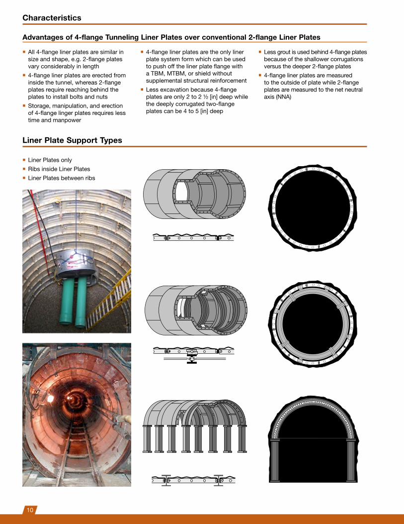
Liner Plates OnlyThe most obvious advantages of this structure are that maximum support per foot of tunnel is obtained with minimum weight of steel. Liner plates, properly groutedorbackfilledastunnelingprogresses, form a dependable structure in either cohesive or non-cohesive ground. Liner plate structures generally require no additional support in tunnels up to 14' in diameter.
Ribs Inside Liner PlatesTo give extra support to a liner plate structure in large diameter or heavy load conditions, ribs can be added inside the ring. Liner plates then act as lagging and are normally lighter in gage.
This additional support usually requires an increase in the diameter of the driven bore to maintain the dimensions of the finishedinsidediameter.Thismethod is often used in shaft construction.
Liner Plates Between RibsThis type of structure is less common than ribs inside liner plates because it is harder to erect. Itdoesofferapracticaltrade-offunder certain tunneling conditions.
Three basic ways sof installing plates in tunnels or shafts are illustrated here; each has its advantage in a particular application or ground condition.
www.dsiunderground.comSection13-Page14 May 2013
Typical Liner Plate Installations
Liner Plates OnlyThe most obvious advantages of this structure are that maximum support per foot of tunnel is obtained with minimum weight of steel. Liner plates, properly groutedorbackfilledastunnelingprogresses, form a dependable structure in either cohesive or non-cohesive ground. Liner plate structures generally require no additional support in tunnels up to 14' in diameter.
Ribs Inside Liner PlatesTo give extra support to a liner plate structure in large diameter or heavy load conditions, ribs can be added inside the ring. Liner plates then act as lagging and are normally lighter in gage.
This additional support usually requires an increase in the diameter of the driven bore to maintain the dimensions of the finishedinsidediameter.Thismethod is often used in shaft construction.
Liner Plates Between RibsThis type of structure is less common than ribs inside liner plates because it is harder to erect. Itdoesofferapracticaltrade-offunder certain tunneling conditions.
Three basic ways sof installing plates in tunnels or shafts are illustrated here; each has its advantage in a particular application or ground condition.
www.dsiunderground.com
Characteristics
Advantages of 4-flange Tunneling Liner Plates over conventional 2-flange Liner Plates
■ All 4-flange liner plates are similar in size and shape, e.g. 2-flange plates vary considerably in length
■ 4-flange liner plates are erected from inside the tunnel, whereas 2-flange plates require reaching behind the plates to install bolts and nuts
■ Storage, manipulation, and erection of 4-flange linger plates requires less time and manpower
■ 4-flange liner plates are the only liner plate system form which can be used to push off the liner plate flange with a TBM, MTBM, or shield without supplemental structural reinforcement
■ Less excavation because 4-flange plates are only 2 to 2 ½ [in] deep while the deeply corrugated two-flange plates can be 4 to 5 [in] deep
■ Less grout is used behind 4-flange plates because of the shallower corrugations versus the deeper 2-flange plates
■ 4-flange liner plates are measured to the outside of plate while 2-flange plates are measured to the net neutral axis (NNA)
Liner Plate Support Types
■ Liner Plates only ■ Ribs inside Liner Plates ■ Liner Plates between ribs
10

Installation Procedure
Introduction
Tunnels excavated by full face, heading and bench, or multiple drift procedures are considered conventional methods. Liner plates used with any construction method utilizing a full or partial shield, a tunneling machine, or other equipment which will exert a force upon the liner plates to propel, steer, or stabilize the equipment are considered special cases and are not covered by these specifications. In any case, liner plates must be assembled in accordance with the manufacturer’s instructions.
Assembly
4-flange liner plates and all accessories required for erection must be transported to the point of installation in advance. Preferably, the unsupported section (span) in the excavation area is always kept at a minimum, and complete liner plate rings are assembled at once. Full-face connection of 4-flange liner plates is accomplished using original bolts and nuts with quick acting coarse thread. The recommended procedure for bolt tightening is “turn of nut” per AISC (American Institute of Steel Construction).
Grouting
It is assumed that grouting is always performed to transfer ground loads to the 4-flange liner plates. Grout holes with plugs shall be provided at a spacing sufficient to allow filling of all voids with grouting material. Grouting or backfilling should start at the lowest grout hole and proceed upward, preferably filling both sides of the tunnel simultaneously. The frequency of grouting depends on ground conditions, tunnel diameter, and total length.
Further References
■ AASHTO Standard Specification for Highway Bridges, Division I, Section 16
■ AREMA Manual for Railway Engineering, Section 4
■ DSI Underground recommendations for the determination of loading on tunnel liner plates
11

0442
7-1U
S/0
5.19
-web
sc
Please note: This brochure serves basic information purposes only. Technical data and information provided herein shall be considered non-binding and may be subject to change without notice. We do not assume any liability for losses or damages attributed to the use of this technical data and any improper use of our products. Should you require further information on particular products, please do not hesitate to contact us.
DSI Tunneling LLC
1032 East Chestnut Street
KY 40204 Louisville
USA
Phone +1-502-473 1010
E-mail [email protected]
www.dsitunneling.com