link techbox / techcard - parker hannifin corporation · · 2008-11-06fitting the techbox to the...
TRANSCRIPT
LI
NK
Tec
hBox
/ T
echC
ard
Product Manual HA470016
!Safety Information
Please read this information BEFORE installing the equipment.
Intended Users
This manual is to be made available to all persons who are required to install, configure or service equipment described herein, or any other associated operation.
The information given is intended to highlight safety issues, and to enable the user to obtain maximum benefit from the equipment.
Application Area
The equipment described is intended for industrial motor speed control using DC or AC motor controllers, with DC motors AC induction or AC synchronous machines.
Personnel Installation, operation and maintenance of the equipment should be carried out by qualified personnel. A qualified person is someone who is technically competent and familiar with all safety information and established safety practices; with the installation process, operation and maintenance of this equipment; and with all the hazards involved.
REFER TO YOUR MAIN PRODUCT MANUAL FOR SPECIFIC SAFETY INFORMATION ABOUT THE
DEVICE YOU ARE CONTROLLING
IMPORTANT It is required that the user be familiar with navigating through the drive MMI menus, be able to select functions and set values and options. For further reading on this topic, refer to the appropriate drive instruction manual. If using DSD, ConfigEd or ConfigEd Lite, it is required the user must be familiar with the software packages.
Copyright © 2008 Parker - SSD Drives All rights strictly reserved. No part of this document may be stored in a retrieval system, or transmitted in any form or by any means to persons not employed by a Parker SSD Drives company without written permission from Parker SSD Drives.
Although every effort has been taken to ensure the accuracy of this document it may be necessary, without notice, to make amendments or correct omissions. Parker SSD Drives cannot accept responsibility for damage, injury, or expenses resulting therefrom.
Printed in the USA HA470016 Issue 5

Contents
Contents.............................................................................................. 3
Chapter 1 - An Overview ..................................................................... 1
6053-LINK-00 TechBox.......................................................................................................1 6055-LINK-00 TechBox.......................................................................................................1 LA463610U003 TechCard.................................................................................................1 Product Features...............................................................................................................2 Part Number and Identification .....................................................................................2
Chapter 2 - Installation ....................................................................... 3
Installing the Option .........................................................................................................3 Wiring ..................................................................................................................................3 Fitting the TechBox to the frame B 605 and 690+ Drives ............................................5 Fitting the TechCard to the 584SV .................................................................................6 Fitting the TechBox to a 590+ and 605/690+frames C and above ..........................7
Chapter 3 - Initial Set-up..................................................................... 8
Configuring the Drive .......................................................................................................8
Chapter 4 - Using DSD Macros and Templates................................. 10
590+ and 690+ Macros/Templates ..............................................................................10
Chapter 5 - Sample Projects ............................................................. 15
Step 1 – Plan the project ...............................................................................................15 Step 2 – Configure the Drive .........................................................................................15 Step 3 – Create a LINK Project .....................................................................................18 Step 4 – Configure the TechCard ................................................................................18 Step 5 – Configure the Touchscreen ...........................................................................18 690+ Macro Sample Configuration .............................................................................24
Chapter 6 – Troubleshooting............................................................. 30
Health and Run LED’s .....................................................................................................30 Module LED......................................................................................................................30 Network LED.....................................................................................................................31 Macro/Drive Diagnostic Functions...............................................................................33
Appendix A-Using Tag Readers and Tag Writers.............................. 34
Link Data Types ...............................................................................................................35 Tag Readers and Writers................................................................................................36
Notes................................................................................................. 39


1
LINK TechBox/TechCard Instruction Manual - HA470016 Issue 5
Chapter 1 - An Overview The LINK TechBox/TechCard option allows standard drives to be a part of the LINK fiber optic network. A computer may be used to provide supervision and monitoring for each drive and other LINK modules in the system.
6053-LINK-00 TechBox This techbox is to be used with the 605 and 690+ frame B. The 6053-L-00 fits into the same location normally occupied by the keypad. If the keypad is needed for the application, it may still be used with a remote mounting kit. An auxiliary 24VDC power supply input allows the techbox to be powered separately from the drive. If the drive shuts down, the network remains intact. A three- position switch provides adjustment of the light intensity transmitted through the fiber.
6055-LINK-00 TechBox This techbox is to be used with the 590+ all frames, 605 and 690+ frames C and higher. The 6055-L-00 plugs into the right side technology box slot beneath the front cover of the drive. The left side location is reserved for feedback technology options. The keypad is unaffected by the presence of a techbox. An auxiliary 24VDC power supply input is provided allowing the techbox to be powered separately from the drive. In the event of a drive shut down, the network integrity remains intact. A three-position switch provides adjustment of the light intensity transmitted through the fiber.
LA463610U003 TechCard For the 584SV, the technology option takes the form of a plug-in card that installs behind the front cover of the drive. The keypad is unaffected by the presence of a techcard. An auxiliary 24VDC power supply input allows the techbox to be powered separately from the drive. If the drive shuts down, the network remains intact. A three-position switch provides adjustment of the light intensity transmitted through the fiber.
Further Reading 605 Drive Instruction Manual. 690+ Drive Instruction Manuals. 590+ Drive Instruction Manual. 584SV Drive Instruction Manual. LINK Overview Manual.
Advantages LINK fiber optic system
1. Inherently noise free since the transmission from module to module is fiber optic. No electrical noise and ground loops to contend with.
2. There is only one fiber that connects the whole network, in place of hundreds of wires. Eliminates wiring mistakes and results in efficient installation and start-up.
3. Network speed is 2.7 MBaud and latency is minimal.
4. Digital transmission is fundamentally less noise-prone than analog methods, and the accuracy of the transmitted data is unaffected by the transmission medium. The use of intelligent devices at either end of the data link allows error checking to be used. This virtually eliminates the effects of electrical noise on data integrity. It is therefore possible to issue setpoints to drives with much higher accuracy using this method.
5. Many hardware devices to choose from, like drives, racks, touchscreens and I/O cards.

2
LINK TechBox/TechCard Instruction Manual - HA470016 Issue 5
Product Features • Available for 605, 690+, 590+ and 584SV products • Compact 5H x 3W x 1D inches • Easy snap on installation • Eliminates hard wired signal connections • Standalone processing with built in macros • Auxiliary power supply input for network backup • Indicator LED’s for Drive and Network status • Direct tag access for all drive parameters
Part Number and Identification The Option can be supplied with the drive or independently. • 605 Drive:
Supplied with the 605 drive: 605/xxx/xxx/x/x/xxx4/xx/xxx
Enclosed in a “Technology Box” for use with the 605 Sizes B: 6053-LINK-00 Enclosed in a “Technology Box” for use with the 605 Sizes C: 6055-LINK-00
• 584SV Drive
Supplied with the 584SV Inverter: 584SV/xxxx/xxx/xxxx/xx/xxx/LINK/xxx/xx/xxx
A “Technology Option” plug-in card for use with the 584SV drive: LA463610U003
• 590+ Drive
Supplied with the 590+ drive: 590P/xxxx/xxx/xxxx/xx/LINK/xxx/xxxx Enclosed in a “Technology Box” for use with the 590+ All Frames: 6055-LINK-00
• 690+ Drive
Supplied with the 690+ drive: 690PB/xxxx/xxx/x/x/xxxx/xxxx/xxxx/LINK/xxx/xxxx
690P/xxxx/xxx/xxxx/xx/xxx/ LINK /xxx/xxx /xxx/xxxx Enclosed in a “Technology Box” for use with the 690+ Size B: 6053-LINK-00 Enclosed in a “Technology Box” for use with the 690+ Sizes C+: 6055-LINK-00

3
LINK TechBox/TechCard Instruction Manual - HA470016 Issue 5
LA463610U003 TECHCARD
Chapter 2 - Installation
Installing the Option
WARNING Before installing, ensure that the drive power is switched off and cannot be
switched on accidentally by other personnel.
Wait 5 minutes after disconnecting power before working on any part of the system or removing the covers from the drive.
Wiring Fiber optic Connections
Recommended Fiber optic Cable Specification CM056316U030
Core Diameter 1000 micron Cable Type Acrylic Bending radius > 1 inch (25.4 mm) Insulation Vinyl > 1KV
For fiber optic connections, use standard 1000 micron acrylic cable (CM056316U030). Connect the fiber optic cable from blue transmit terminal on any one techbox or techcard, to the black receive terminal on the next module until the loop is closed, as shown in Figure 1.
6053-L-00 TECHBOX
To computer
Figure 1-Sample Link
To computer
Fiber optic cable Fiber optic cable
External Power External Power
To computer
External Power
6055-L-00 TECHBOX
Model No: 6055-L-00
Serial No: 1234567890ABCD |||||| ||||||||||||||||||| |||||||||
Internal External
TB1
24V
C
OM
G
ND

4
LINK TechBox/TechCard Instruction Manual - HA470016 Issue 5
Computer Connections – Socket (J2) A computer connected to the RJ15 socket on any LINK module can be used to configure or monitor any element within the Link network. SSD Drives graphic configuration software package Drive System Designer (DSD) version 1.07 or ConfigEd version 5.13 (database properties of platform rev. 14-0, library rev. 114-0, instruction rev. 9-0 and class rev. 904-0), and all subsequent versions supports this option. If you have an older version, updates may be obtained simply by contacting Parker SSD product support.
Use the cable that was supplied with your DSD or ConfigEd package. Plug the larger end into your computer serial port (using the DB9to RJ11 adapter supplied), and the other end (RJ15) into the socket on the LINK TechBox/TechCard.
External Power Connections (Optional) Terminal Block (TB1) The plug-in connectors for TB1 are physically different for the 6055-L-00 TechBox, LA463610U003 TechCard and the 6053-L-00 TechBox.
Note: Power requirements: 24vdc rated for 200ma inrush and 65ma steady state.
CAUTION Terminal orientation will be different for 6055-L-00, LA463610U003 and 6053-L-00. The table below refers to “6055-L-00, LA463610U003 Position” and “6053-L-00 Position”, as viewed from the front of the drive with the Technology Option fitted to the drive. Failure to heed this note will damage the card and void the warranty.
6055-L-00,
Position 6053-L-00 Position
Terminal Description
LEFT RIGHT +24 VDC supply
CENTER CENTER COM (0V) supply
RIGHT LEFT GROUND
External Power Jumper (J3) The “External Power” jumper (on the rear of the 6053-L-00 TechBox) (on the front of the 6055-L-00 TechBox and LA463610U003 TechCard) is factory set for “Internal Power”. This jumper should be left in the “Internal Power” position, unless the techbox is being fed with an external 24 VDC power source. When external power is being selected, move the jumper from the INTERNAL (Left) position and reinsert the jumper in the EXTERNAL (Right) position. Connect the external power leads to TB1 according to the above-mentioned table.
Internal External
LA463610U003TechCard
6053-L-00 and 6055-L-00 TechBox

5
LINK TechBox/TechCard Instruction Manual - HA470016 Issue 5
Transmit Strength Settings - Switch (SW1) Set this switch to select the transmission intensity of the light. Use the table below to choose the position after determining the approximate length of the ‘transmit’ fiber optic cable to the next LINK element.
6055-L-00, LA463610U00
Position
6053-L-00 Position
Intensity Transmit Range
CENTER CENTER LOW 0 – 20 m (0 – 66 ft)
UP DOWN MEDIUM 21 – 40 m (67 – 132 ft)
DOWN UP HIGH 41 – 60 m (133 – 196 ft)
CAUTION Switch orientation is different for 6055-L-00, LA463610U003 and 6053-L-00. The table above refers to “6055-L-00, LA463610U003 Position” and “6053-L-00 Position”, as viewed from the front of the drive with the Technology Option fitted to the drive. Setting the transmit strength switch to the wrong setting will result in incorrect light intensity and may cause the LINK network to malfunction.
Fitting the TechBox to the frame B 605 and 690+ Drives WARNING!
Ensure that all power is off prior to working on the drive
The option is supplied as a “6053-L-00 Technology Box” which fits into the front of the 605 and 690+ drive in place of the keypad or blank cover. • Remove the terminal cover and
screws. • Plug the ribbon cable into the
back of the TechBox and into the socket on the 605B or 690+B drive
• Snap the TechBox into place in the recess on the front of the 605B or 690+B
• Make all user-wiring connections. Connect all shields to the ground post on the chassis. Make a connection from the TechBox TB1 ground terminal to the ground post on the chassis.
• Re-install the terminal cover securely with the screws. Note: If permanently using the keypad with the Technology Box fitted, mount the keypad
remotely using the Panel Mounting Kit with part number (6052). The connecting lead enters the 605 Inverter through the gland plate.
IMPORTANT: Remember to set the transmit strength setting on switch, SW1.

6
LINK TechBox/TechCard Instruction Manual - HA470016 Issue 5
Fitting the TechCard to the 584SV The option is supplied as a “Technology Option” board. It is factory-fitted to the control board inside the drive.
Warning Ensure that all power is off
prior to working on the drive.
Caution When handling the board, observe electrostatic control precautions.
584SV Frames 4, 5 & 6 • Remove the terminal cover with the captive
screws. Slide off the metal cover after removing the retaining screw. The technology option is fitted to the control board, as shown.
• When wiring connections have been made, reinstall the terminal cover and secure with screws. 584SV Frames 7, 8, 9 & 10 • Remove the terminal cover with the
captive screws.
The Technology Option is fitted to the Control Board, as shown.
• When wiring connections have been made, refit the terminal cover and secure with screws.
IMPORTANT: Remember to set SW1 for the correct intensity.
Technology
TerminalCover
Option
Control Board
Metal Cover
Termina lCover
Control Board
TechnologyOption

7
LINK TechBox/TechCard Instruction Manual - HA470016 Issue 5
Fitting the TechBox to a 590+ and 605/690+frames C and above
The option is supplied as a “6055-L-00 TechBox” which fits into the lower right front of the 605C/690+C - F drive.
Note: The 6055-L-00 TechBox does not affect the operation of the 6051/6901 keypad.
WARNING! Ensure that all power is off
prior to working on the drive.
• Remove the terminal cover.
• Plug the techbox into the socket located in the lower right side 605C or 690+C-F drive.
• Tighten the screw to secure the techbox to the drive. This also serves as a ground connection for the TechBox.
• Make all user-wiring connections. Connect all shields to the ground post on the chassis.
• Re-install the terminal cover securely with the screws.
605C, 690+ C-F frames 590+ all frame sizes
IMPORTANT: Remember to set SW1 for the correct intensity.

8
LINK TechBox/TechCard Instruction Manual - HA470016 Issue 5
Chapter 3 - Initial Set-up
Configuring the Drive The first step in using the technology option is configuring the drive to accept the TechBox. The keypad (MMI), DSD/ConfigEd (LINK programming software) or ConfigEd Lite (SSD Drives’ device level configuration software), must be used to configure the TEC OPTION function block parameters inside the drive before commissioning the LINK technology option.
The parameter names/functions in this function block are inter-dependent and will change with different parameter values and various technology options.
The Function Block diagram below shows the DSD and ConfigEd Lite parameter names, which are also displayed on the MMI if no Option is fitted or an incorrect TYPE is selected for the fitted Option.
IMPORTANT The user must be familiar with navigating through the drive MMI menus, be able to select functions and set values and options. For further reading on this topic, refer to the appropriate drive instruction manual. If using DSD/ConfigEd or ConfigEd Lite, the user must be familiar with the software package.
Under TYPE, select LINK.
.
Parameter Descriptions TYPE Range: Enumerated - see belowSelects the type of TechBox.
Enumerated Value : Technology Option 0 : NONE 1 : RS485 2 : PROFIBUS DP 3 : LINK 4 : DEVICENET 5 : CANOPEN 6 : LONWORKS 7 : TYPE 7
MMI Menu Map
1 SETUP PARAMETERS
2 FUNCTION BLOCKS
3 SERIAL LINKS
4 TEC OPTION
TEC OPTION TYPE
TEC OPTION IN 1
TEC OPTION IN 2
TEC OPTION IN 3
TEC OPTION IN 4
TEC OPTION IN 5
TEC OPTION FAULT
TEC OPTION VER
TEC OPTION OUT 1
TEC OPTION OUT 2

9
LINK TechBox/TechCard Instruction Manual - HA470016 Issue 5
FAULT Range: Enumerated - see belowThe fault state of the Technology Option card.
Enumerated Value : Fault State
0 : NONE: Normal operating mode. 1 : PARAMETER: Confirm that tag exists in the LINK Configuration. 2 : TYPE MISMATCH: Confirm that type of tag is valid. 3 : SELF TEST: The self test has failed. Replace TechCard/TechBox. 4 : HARDWARE: Hardware error. Replace TechCard/TechBox. 5 : MISSING: TechCard/TechBox not installed/
VERSION Range: 0000 to FFFF The version of the Technology Option. If no option is fitted then the version is set to zero.
INPUTS (1–5)
Range: 0000 to FFFF
Not used with the LINK Technology Option
OUTPUTS (1–2)
Range: 0 to 9999
Not used with the LINK Technology Option
Other Function blocks While configuring the “TEC OPTION”, you may also insert other Link function blocks into the TechBox template. This can be done by using ConfigEd or DSD.
DSD and ConfigEd When configuring the “TEC OPTION” function block using DSD the TechBox and drive can be programmed completely using the DSD software. Drive System Designer (DSD) provides the TechBox templates for the 590+ and 690+ only. When using ConfigEd to program the TechBox Tag Readers and Tag Writers are used.
Install If using the MMI, remember to save the set-up via the Save Parameters or Save Config menu. If using ConfigEd Lite install the configuration into the drive through the P3 port (RS232 configuration port), using the Command/Install pulldown menu. For more details on installing a configuration, refer to the ConfigEd Lite Instruction Manual (RG352747) Chapter 4 page 4-7. If using ConfigEd or DSD, install the configuration using socket J2 on the Link TechBox (RS232 configuration port) Command/Install pulldown menu. For more details on installing a configuration, refer to the ConfigEd Instruction Manual (RG353792) Chapter 4 page 4-26.
10
LINK TechBox/TechCard Instruction Manual - HA470016 Issue 5
Chapter 4 - Using DSD Macros and Templates
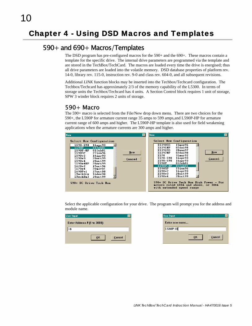
590+ and 690+ Macros/Templates The DSD program has pre-configured macros for the 590+ and the 690+. These macros contain a template for the specific drive. The internal drive parameters are programmed via the template and are stored in the TechBox/TechCard. The macros are loaded every time the drive is energised; thus all drive parameters are loaded into the volatile memory. DSD database properties of platform rev. 14-0, library rev. 115-0, instruction rev. 9-0 and class rev. 604-0, and all subsequent revisions.
Additional LINK function blocks may be inserted into the Techbox/Techcard configuration. The Techbox/Techcard has approximately 2/3 of the memory capability of the L5300. In terms of storage units the Techbox/Techcard has 4 units. A Section Control block requires 1 unit of storage, SPW 3 winder block requires 2 units of storage.
590+ Macro The 590+ macro is selected from the File/New drop down menu. There are two choices for the 590+, the L590P for armature current range 35 amps to 599 amps,and L590P-HP for armature current range of 600 amps and higher. The L590P-HP template is also used for field weakening applications when the armature currents are 300 amps and higher.
Select the applicable configuration for your drive. The program will prompt you for the address and module name.

11
LINK TechBox/TechCard Instruction Manual - HA470016 Issue 5
The macro has some preconfigured inputs and outputs as default. If another tag or parameter is needed, it can be added inside the macro. It is possible to use both the drives’ internal function blocks and the Link function blocks. Simply double-click on the macro to access the 590+ internal function blocks.
The macro has a built in Communications Watchdog. The Watchdog consists of Link system blocks and drive function blocks. If the Link network goes down, the drive will be disabled via digital output 3(B7) and start input (B3).

12
LINK TechBox/TechCard Instruction Manual - HA470016 Issue 5
Modifying inside the macro All the drive functions are available through the TechBox. When using some of the 590+ drive functions it may be necessary to use the Mini-Link block or a system block as the connection point to the TechBox. The purpose for doing this is to ensure proper triggering of non-system function blocks.
Note: The 690+ drive does not require the use of a system block to ensure proper triggering.
Deleting and/or moving an internal connection The connections inside the macro can be deleted or moved in the same fashion that is used in ConfigEd or DSD. When deleting the connection and the connection point be sure the connection outside the macro is deleted first. If the connection is only being moved from one block to another block it is not necessary to delete the external macro connection.
Inserting a new internal connection Input connection points to the 590+ macro do not need to be connected to the Mini-Link block. When you are adding an output connection point to the 590+ macro it may be necessary to connect to the Mini-Link or system block. If the output connection point is originating from a system block it is not necessary to link the connection to the Mini-Link block. The connection is normalized so that scaling the signal is not necessary outside the macro.
Inserting function blocks Link function blocks may be programmed into the TechBox. LINK function blocks should be inserted outside the macro. Do not insert function blocks inside the drive macro. The macro inputs and outputs are normalized when connectioning to the drive through the macro. The function blocks are accessed in the same manner as other Link2 modules.
Inserting and deleting macro inputs/outputs Connections in and out of the macros are made by the following methods.
1. Selecting the inputs and outputs from the BLOCK menu will allow the I/O diamonds to be inserted into the macro. The diamond shaped input and output tags can be dropped anywhere inside the drive macro. Drawing a link from the input/output diamond to the desired connection point will make the connection to outside the macro.
2. Highlighting the tag and pressing the “DELETE” key will delete inputs or outputs. Prior to deleting the tag, be sure to disconnect all external connections to the macro.

13
LINK TechBox/TechCard Instruction Manual - HA470016 Issue 5
Note: Internal tags do not get a module address or slot address. The tag appears as a connection point on the outside of the macro. Double clicking on the diamond will allow you to change the name of the tag. This name will appear inside and outside the macro. The number preceeding the tag name controls the order of appearance on the macro outside connection points. The number may be changed in the same manner as changing the name of the tag. Input connection points to the 590+ macro do not need to be connected to the Mini-Link block. When adding an output connection point to the 590+ macro it may be necessary to connect to the Mini-Link or system blocks.
3. Certain output tags will require an entry for the connection speed. The faster connection speeds require more of the CPU heap usage. If too many fast connections are made, it may be possible to run out of CPU heap and cause an “L-Error” fault. Keep fast connections to a minimum.
14
LINK TechBox/TechCard Instruction Manual - HA470016 Issue 5
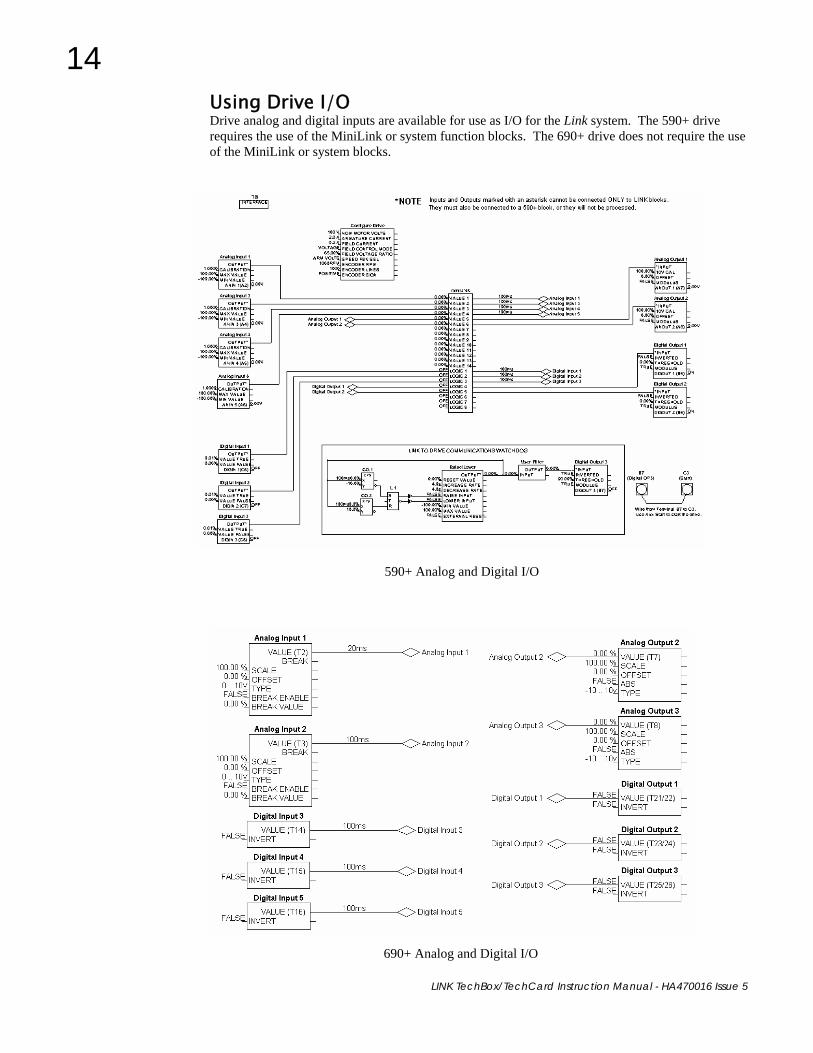
Using Drive I/O Drive analog and digital inputs are available for use as I/O for the Link system. The 590+ drive requires the use of the MiniLink or system function blocks. The 690+ drive does not require the use of the MiniLink or system blocks.
690+ Analog and Digital I/O
590+ Analog and Digital I/O

15
LINK TechBox/TechCard Instruction Manual - HA470016 Issue 5
Chapter 5 - Sample Projects
To demonstrate the use of a LINK Technology Option, here are two simple projects consisting of a 584SV drive, with a LA463610U003 TechCard, or 690+ drive with a 6053/6055 TechBox and an L5392 touchscreen. Our first example uses a 584SV, the second example uses a 690+. By configuring these pieces, we will build a LINK project that will:
• Start, stop and jog the drive from the touchscreen • Display health status and trips • Set line speed • Monitor motor speed, frequency, voltage and current
Step 1 – Plan the project Before any configurations are done, make list of parameters that need to be accessed in the drive. Go to the “Specification Table – Tag Number Order” section in the drive instruction manual to identify all tags. For this example they are:
TAG R / W Description Type Scaling 291 Write Start Command Ordinal - 277 Write Fast Stop Ordinal - 278 Write Coast Stop Ordinal - 294 Write Reverse Direction Ordinal - 280 Write Jog Command Ordinal - 130 Write Speed Setpoint Value 1 = 120% 592 Read Motor Volts Ordinal - 70 Read Motor Load Value 200% = 1 255 Read Speed Feedback Value 120% = 1
6 Read Drive Status Ordinal - 591 Read Output Frequency Ordinal - 52 Read Drive Healthy Ordinal - 285 Read Drive Running Ordinal -
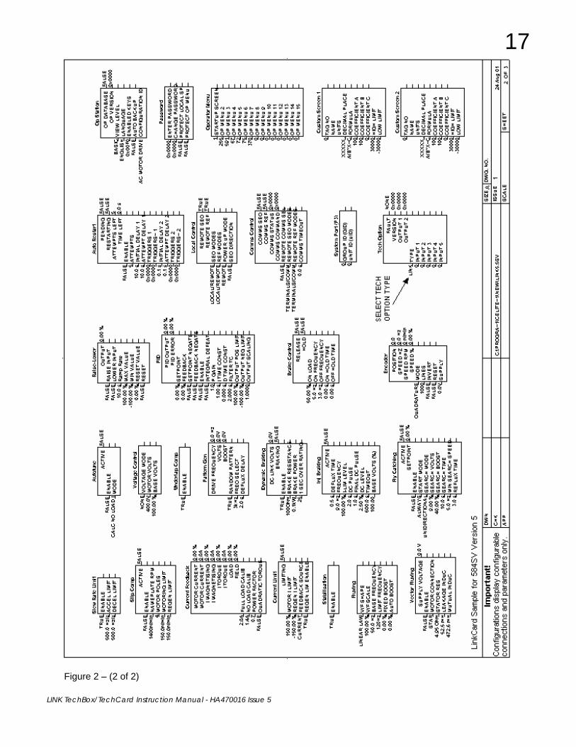
Step 2 – Configure the Drive 584SV/605 Using the drive MMI, preferably ConfigEd Lite, configure the drive as shown in Figure 2. These instructions will also apply to the 690+ if using ConfigEd. The changes from default are:
• Drive Start Command goes to Sequencing Logic\Run Fwd. (Break the default connection to Run Fwd).
• Break all input connections to Value Function 1. (Speed Reference goes to Value Function 1\Input A).

16
LINK TechBox/TechCard Instruction Manual - HA470016 Issue 5
Figure 2 – (1 of 2)
17
LINK TechBox/TechCard Instruction Manual - HA470016 Issue 5
Figure 2 – (2 of 2)

18
LINK TechBox/TechCard Instruction Manual - HA470016 Issue 5
Step 3 – Create a LINK Project In ConfigEd, create a new project by using the Project/Manage menu. Refer to the ConfigEd instruction manual HA353792 for details.
Step 4 – Configure the TechCard 1. In the selected project, open a default Techbox template by going to File/New/LtechBx2.
2. Enter the address (in this case: 10) and the file name (in this case: SVL-10), when prompted.
3. Insert an Ordinal Writer block from the pulldown menu Block/Techbox/Ordinal Writer.
4. Give it a name OR1 (happens automatically) and double-click on it.
5. Under Tag Number, enter 592. Close the window.
6. Similarly, insert the other blocks required and connect them together as shown in Figure 3, to complete the configuration.
Step 5 – Configure the Touchscreen 1. In the correct project, open a default Multi-Page L5392 LinkScreen template by going to
File::New::L5392MP
2. Enter the address (in this case: 11) and the file name (in this case: 5392-11), when prompted.
3. Insert the blocks required and connect them together as shown in Figure 4, to complete the configuration.
4. ANNC.1 is an annunciator block that will show fault messages, should they occur. These legend messages need to be entered in ANNC.1. Decoding information may be found in the “Specification Table: Tag Number Order/ Tag 6” in the drive instruction manual HA463617. Refer to figure 5.
5. The resulting touchscreen layout is shown below.
Drive Healthy
Reverse Jog
Start Stop
Speed Setpoint
Motor Load
Page 1
Fast Stop Coast Stop
Start Stop
Speed Feedback
Frequency
Page 2
Motor Volts
Figure 3

19
LINK TechBox/TechCard Instruction Manual - HA470016 Issue 5
Figure 4 – (1 of 4)

20
LINK TechBox/TechCard Instruction Manual - HA470016 Issue 5
Figure 4 – (2 of 4)

21
LINK TechBox/TechCard Instruction Manual - HA470016 Issue 5
Figure 4 – (3 of 4)

22
LINK TechBox/TechCard Instruction Manual - HA470016 Issue 5
Figure 4 – (4 of 4)

23
LINK TechBox/TechCard Instruction Manual - HA470016 Issue 5
Figure 5

24
LINK TechBox/TechCard Instruction Manual - HA470016 Issue 5
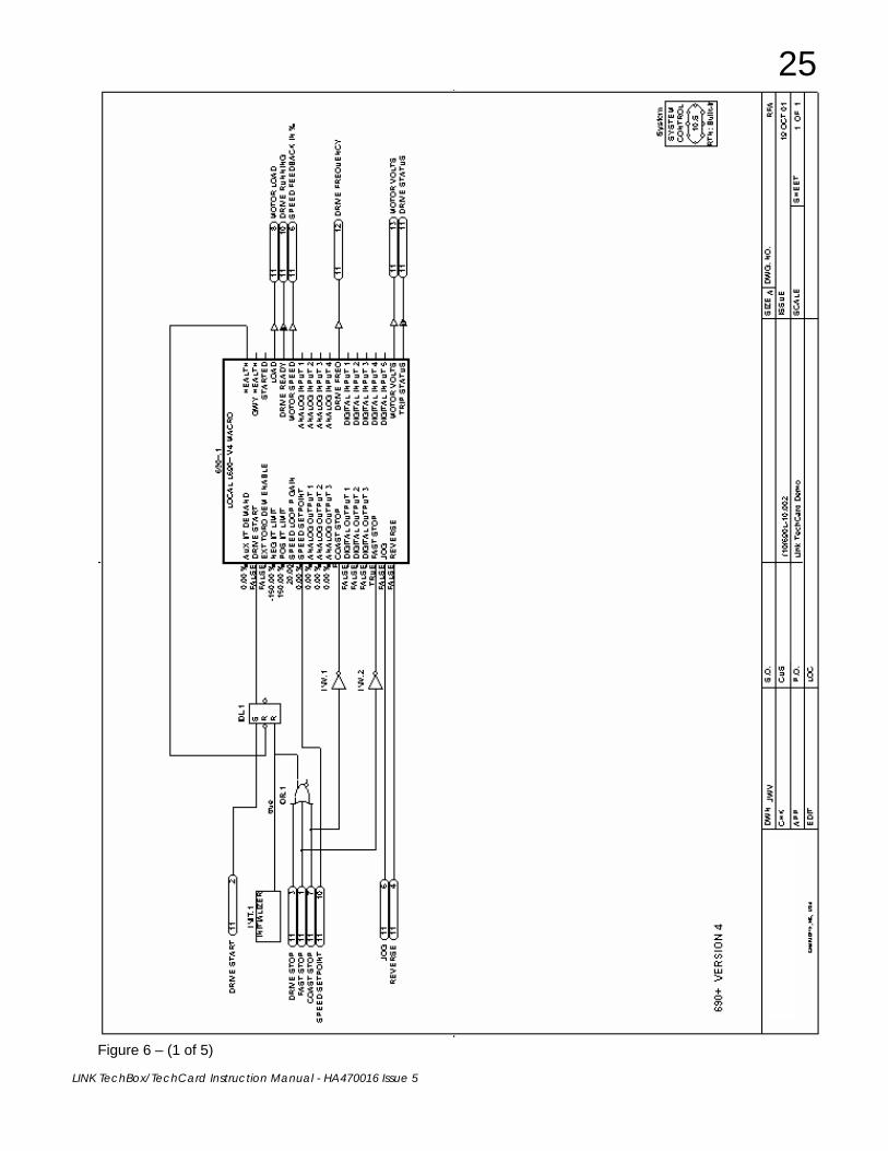
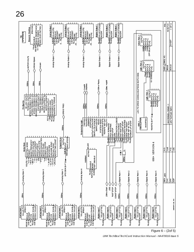
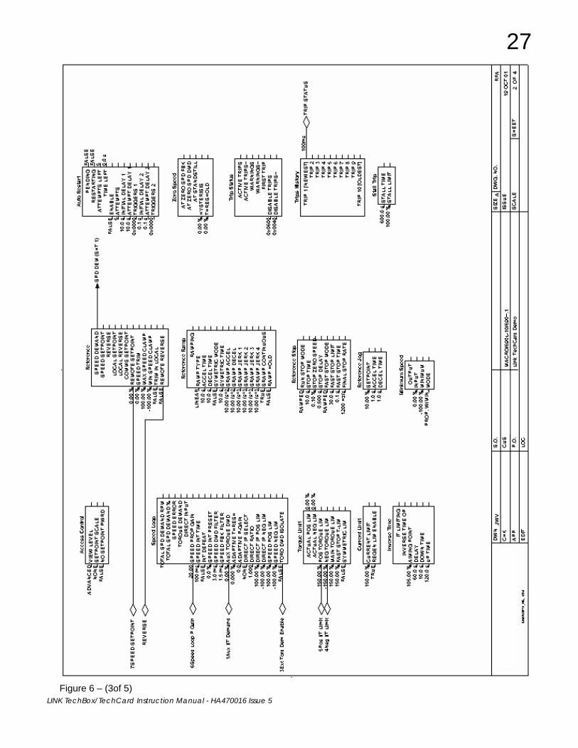
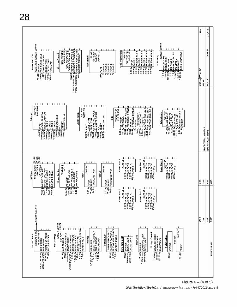
690+ Macro Sample Configuration Select the 690+ template with the correct version firmware from the “NEW” menu.
After completing the above steps you should see the 690+ macro without any Link connections. Make the necessary connections and changes to make the configuration look like Figure 6.
25
LINK TechBox/TechCard Instruction Manual - HA470016 Issue 5
Figure 6 – (1 of 5)
26
LINK TechBox/TechCard Instruction Manual - HA470016 Issue 5
Figure 6 – (2of 5)
27
LINK TechBox/TechCard Instruction Manual - HA470016 Issue 5
Figure 6 – (3of 5)
28
LINK TechBox/TechCard Instruction Manual - HA470016 Issue 5
Figure 6 – (4 of 5)

29
LINK TechBox/TechCard Instruction Manual - HA470016 Issue 5
Figure 6 – (5 of 5)

LINK TechBox/TechCard Instruction Manual - HA470016 Issue 5
LA463610U003 TECHCARD
Chapter 6 – Troubleshooting
Health and Run LED’s Health and Run are drive functions and are not associated with the operation of the technology feature.
On the 605/690 frames A&B the techbox is mounted in place of the keypad or blank cover. The Run and Health LED’s from the keypad are replicated on the face of the techbox. The bottom two LED indicators for the module and network status.
On the 584SV, 605C, 690 frames C and above, 590+ the Run and Health LED’s are on the drive itself. Located on the TechCard and the TechBox are 2 LEDs that indicate the status of the module and the LINK network.
Module LED This indicates the set-up state of the Technology Box/Option
LED STATE FAULT DESCRIPTION OFF No Power If jumper J3 set for INT: Apply power to drive
If jumper J3 set for EXT: Apply external power
SLOW FLASH (2 flashes/sec)
Fault during initialization
Self Test failure Module does not have a valid configuration
QUICK FLASH (4 flashes/sec)
Off LINK network
Module was halted (probably by LINK tools) Module is attempting to go on-line Problem in the configuration (L-error, H-error or duplicate address)
ON None Module is running its configuration and communicating over the LINK network
6055-L-00 TECHBOX
6053-L-00 TECHBOX
Model No: 6055-L-00
Serial No: 1234567890ABCD |||||| ||||||||||||||||||| |||||||||
Internal External
TB1
24V
C
OM
G
ND

31
LINK TechBox/TechCard Instruction Manual - HA470016 Issue 5
Network LED This indicates the state of the connected network.
LED STATUS DESCRIPTION OFF Network failure
Module halted or initializing
ON Network healthy Module peer halted or duplicate address
Note: The NETWORK LED can only be in the ON state when the MODULE LED is ON continuously, indicating that the Option is ready for external communications.
Note: Early versions of the 584SV techcard may not have the LED’s fitted.
NCP STATE Techbox State Module LED Network LED 0 Initializing Initializing Slow Flash Off 1 Halt Config Fast Flash Off
2 No Config Fault Slow Flash *
3 L-error Fault Fast Flash *
4 H-error Fault Fast Flash * 5 Self Test Fail Fault Slow Flash *
6 Shutdown Stopping
7 OK Running On On
8 Network Warning Running On On
9 Network Failure Running On Off
A Checking Network Starting Fast Flash *
B Peer Halted Starting Fast Flash On
C Duplicate Address Fault Fast Flash On
* LED state depends on whether the network is active at this node’s receiver
Ordinal Diagnostic Function Block The Diagnostic Function block is inserted as any other block in ConfigEd mode. Later, while on-line in Setup And Monitor mode (SAM), the tag number of the Diagnostic block may be edited (unlike regular function blocks) to display and monitor different drive parameters.
In ConfigEd mode: From the Block/Techbox menu select Ordinal Diagnostic. Drag and place it in the configuration.
In the SAM mode: Click on Update Full under the Window menu. This accesses the LINK network and opens up a module list that contains all the elements on the ring. Double-click the techbox line and the configuration will open in SAM mode.
LINK TechBox/TechCard Instruction Manual - HA470016 Issue 5
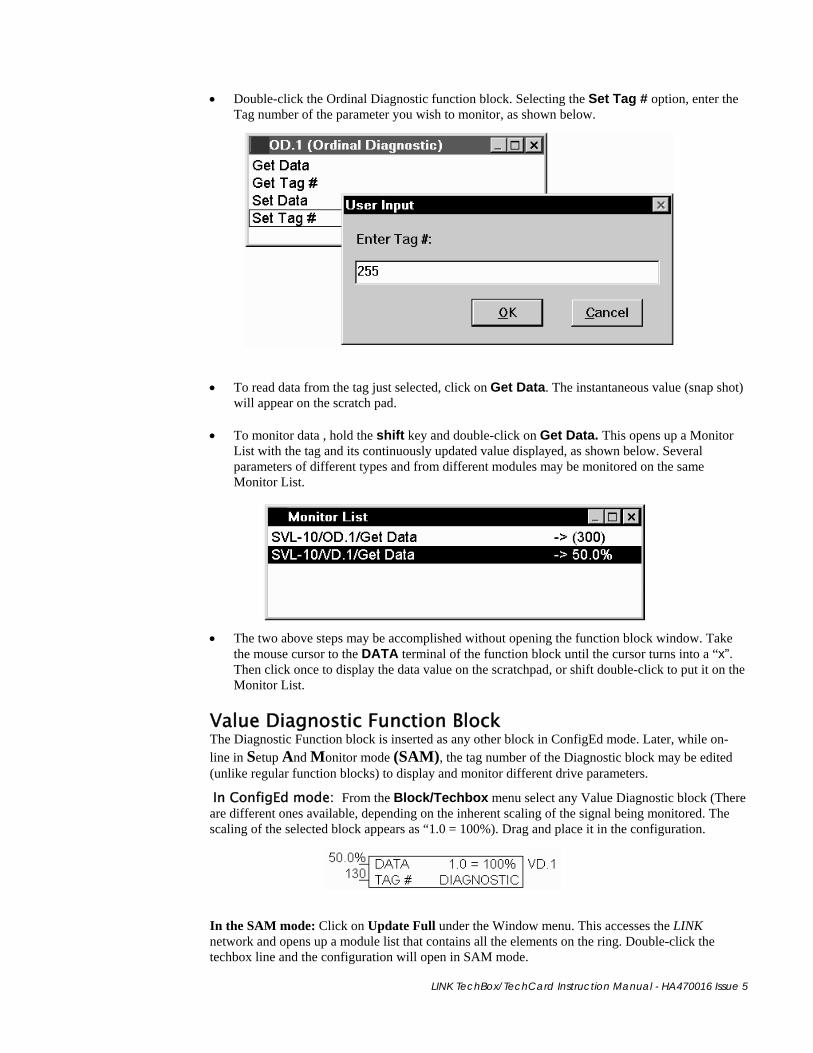
• Double-click the Ordinal Diagnostic function block. Selecting the Set Tag # option, enter the Tag number of the parameter you wish to monitor, as shown below.
• To read data from the tag just selected, click on Get Data. The instantaneous value (snap shot) will appear on the scratch pad.
• To monitor data , hold the shift key and double-click on Get Data. This opens up a Monitor List with the tag and its continuously updated value displayed, as shown below. Several parameters of different types and from different modules may be monitored on the same Monitor List.
• The two above steps may be accomplished without opening the function block window. Take the mouse cursor to the DATA terminal of the function block until the cursor turns into a “x”. Then click once to display the data value on the scratchpad, or shift double-click to put it on the Monitor List.
Value Diagnostic Function Block The Diagnostic Function block is inserted as any other block in ConfigEd mode. Later, while on-line in Setup And Monitor mode (SAM), the tag number of the Diagnostic block may be edited (unlike regular function blocks) to display and monitor different drive parameters.
In ConfigEd mode: From the Block/Techbox menu select any Value Diagnostic block (There are different ones available, depending on the inherent scaling of the signal being monitored. The scaling of the selected block appears as “1.0 = 100%). Drag and place it in the configuration.
In the SAM mode: Click on Update Full under the Window menu. This accesses the LINK network and opens up a module list that contains all the elements on the ring. Double-click the techbox line and the configuration will open in SAM mode.

33
LINK TechBox/TechCard Instruction Manual - HA470016 Issue 5
• Double-click the Value Diagnostic function block. Selecting the Set Tag # option, enter the Tag number of the parameter you wish to monitor, as shown below.
• To read data from the tag just selected, click on Get Data. The instantaneous value (snap shot) will appear on the scratch pad.
• To monitor data , hold the shift key and double-click on Get Data. This opens up a Monitor List with the tag and its continuously updated value displayed, as shown below. Several parameters of different types and from different modules may be monitored on the same Monitor List.
• The two above steps may be accomplished without opening the function block window. Take the mouse cursor to the DATA terminal of the function block until the cursor turns into a “x”. Then click once to display the data value on the scratchpad, or shift double-click to put it on the Monitor List.
Macro/Drive Diagnostic Functions The techbox allows you to monitor the drive inside the macro. The drive function blocks are accessed through the normal Setup And Monitor methods.

LINK TechBox/TechCard Instruction Manual - HA470016 Issue 5
Appendix A-Using Tag Readers and Tag Writers With the drive configured to accept the LINK Technology Option, the interface between the Techbox/Techcard, the drive and the LINK system needs to be programmed for the specific drive and application. The Techbox/Techcard can be perceived as a LINK processor, which treats the host drive as an I/O device. Drive parameters are accessed by tag numbers which are unique to each parameter and can be found under “Specification Table – Tag Number Order” in the drive instruction manual.
Function Blocks ConfigEd has two types of function blocks for the LINK Techbox/TechCard: Tag Reader block that reads a drive parameter; the Tag Writer block that writes to a drive parameter.
Each of these blocks can be subdivided into two classes, Ordinal and Value. Ordinal Readers and Writers handle integer or logic data and cannot be scaled. Value Readers and Writers handle continuous variables and have special scaling assigned to them. Scaling choices are representative of standard ranges found in a drive and include choices of 100%, 120%, 150% and 200%, each representing a full scale “1” within LINK. You will need ConfigEd (version 5.13), or DSD with database properties of platform rev. 14-0, library rev. 115-0, instruction rev. 9-0 and class rev. 604-0, and all subsequent revisions, to build a configuration for the LINK techbox. For details on how to use this package, refer to the ConfigEd instruction manual RG353792.
Additional LINK function blocks may be inserted into the Techbox/Techcard configuration. The Techbox/Techcard has approximately 2/3 of the memory capability of the L5300. In terms of storage units the Techbox/Techcard has 4 units. A Section Control block requires 1 unit of storage, SPW 3 winder block requires 2 units of storage.
Loading a TechBox Function Block
WARNING LINK configurations should be created by qualified personnel who have a thorough understanding of drive systems and who are LINK trained by Parker SSD Drives. Potentially dangerous configurations are possible and Parker SSD
Drives is not responsible for any resulting consequences or damages.
• In ConfigEd, open up the project in which this techbox will appear. • From the File/New menu, pick LTechBx2, the default template for a LINK techbox/techcard.
This template contains an AUTO-TAG LOADER. The AUTO-TAG-LOADER will automatically access and load parameters into the drive during the power up sequence. (The L TechBox template contains a MANUAL-TAG-LOADER function block. The parameters in the tag readers and writers are manually triggered.)
• When prompted, furnish the node address and name for the techbox. • Two blocks should be visible on a blank page, named TBI and System.
Manual Tag Load Automatic Tag LoadSystem Control Block

35
LINK TechBox/TechCard Instruction Manual - HA470016 Issue 5
• No user settings are necessary for this block. When the Tag Load input goes high, the ‘loadable’ writers insert their current values to the respective drive tags.
Double-click on the System Control block to access the three restart preferences, as shown above. In most cases, the defaults are sufficient. For details, refer to the ConfigEd instruction manual (RG353792).
Link Data Types The three types of data in LINK are Logic, Ordinal and Value.
Logic Signals Used for all logic functions, they are True or False signals that take the form of 1 and 0. True = 1, False = 0 All Logic function blocks in LINK, operate this way.
Note: Logic 1 = Ordinal 1, Logic 0 = Ordinal 0
Ordinal Signals Ordinals are whole, unsigned integers, used mainly for counters and enumeration. These numbers range from 0-32,767 or 0-65,535.
Value Signals These are used for signal processing. The range of values is –1 to +1 in LINK, represented by –100% to +100% in DSD or ConfigEd.
Scaling There is no over-range built into the LINK Value number. This means that the maximum value a number can take is 1.0. In drives and control systems, an over-range is necessary to allow feedback control of a variable when it is operating at full range. Therefore, an over-range must be built into the number range when the system is being configured. It is for this reason that LINK values for certain different variables have different scaling properties. These rules need to be followed in the Link system design when interfacing the techbox with other LINK function blocks.
Generic values These are values that need no over-ranging.
100% of the variable = 100% in LINK
Example: A speed ratio signal. Range 75% to 100% Use the Value Reader 100 and Value writer 100 blocks in your techbox configuration.

LINK TechBox/TechCard Instruction Manual - HA470016 Issue 5
Speed values A drive running at full line speed may need to exceed that speed to satisfy a controlled variable.
100% of drive speed = 83.3333% in LINK which is the same as 120% of drive speed = 100% in LINK
Example: A line speed signal from a LINK Master Ramp to a drive section. Range 0% to 83.3333%
When using speed values in LINK configurations, it is necessary to multiply the reference signal to the drive by 83.3333%. Some special function blocks like the Master Ramp already have this multiplier built in. Refer to specific function block help sheets for details.
Note: While it is necessary to multiply the speed reference by 83.3333%, it follows that the speed feedback signal coming back from the drive needs to be divided by 83.3333%. Use the Value Reader 120 and Value Writer 120 blocks in your techbox configuration.
Current values A drive may occasionally need to exceed its rated continuous current and go into a short-term overload condition.
200% of drive current = 100% in LINK
Example: A load indicating signal. Range -200% to +200% When using current (torque/load) values in LINK configurations, it is necessary to multiply the reference signal to the drive by 50%.
Note:While it is necessary to multiply the current (torque) reference by 50%, it follows that the current (torque, load) feedback signal coming back from the drive needs to be divided by 50%. Use the Value Reader 200 and Value Writer 200 blocks in your techbox configuration.
Tag Readers and Writers Ordinal Reader Function Block From the Block/Techbox menu select Ordinal reader. Drag and place it towards the left edge of your sheet.
Double-click on it and select settings, as shown below.
• Select the tag number associated with the parameter to be read. This may be found under “Specification Table – Tag Number Order” in the drive instruction manual.
• Poll period should be set to a realistic value, fast enough to be read continuously, yet not so fast, that it overloads the processor. Reads are typically recommended at 200 ms.
• Click the output terminal and drag it to the next LINK block in the configuration.
Output terminal

37
LINK TechBox/TechCard Instruction Manual - HA470016 Issue 5
Ordinal Writer Function Block From the Block/Techbox menu select Ordinal Writer. Drag and place it towards the right edge of your sheet.
Double-click on it and select settings, as shown below.
• Select the tag number associated with the parameter to be written to. This may be found under “Specification Table – Tag Number Order” in the drive instruction manual.
• If necessary, a preset value may be entered into the Preset field. Remember that this value will be overwritten when a new value comes over the input connection of the function block.
Value Reader Function Blocks From the Block/Techbox menu select any Value reader. Drag and place it towards the left edge of your sheet.
Double-click on it and select settings, as shown below.
• Select the tag number associated with the parameter to be read. This may be found under “Specification Table – Tag Number Order” in the drive instruction manual.
• Poll period should be set to a realistic value, fast enough to be read continuously, yet not so fast, that it overloads the processor. Reads are typically recommended at 200 ms.
• Click the output terminal and drag it to the next LINK block in the configuration. H I N T: There are different value reader function blocks that can be selected, depending on the inherent
scaling of the signal. For example, to read a generic parameter, pick the Value Reader 100 function block, which yields a 100% scaling equal to a full scale “1” in LINK. For a speed feedback signal, pick the Value Reader 120 function block, which yields a 120% scaling equal to a full scale “1” in LINK. Similarly, for a current feedback signal where 200% current equals a “1” in LINK, pick Value Reader 200.
Input terminal
Output terminal
LINK TechBox/TechCard Instruction Manual - HA470016 Issue 5
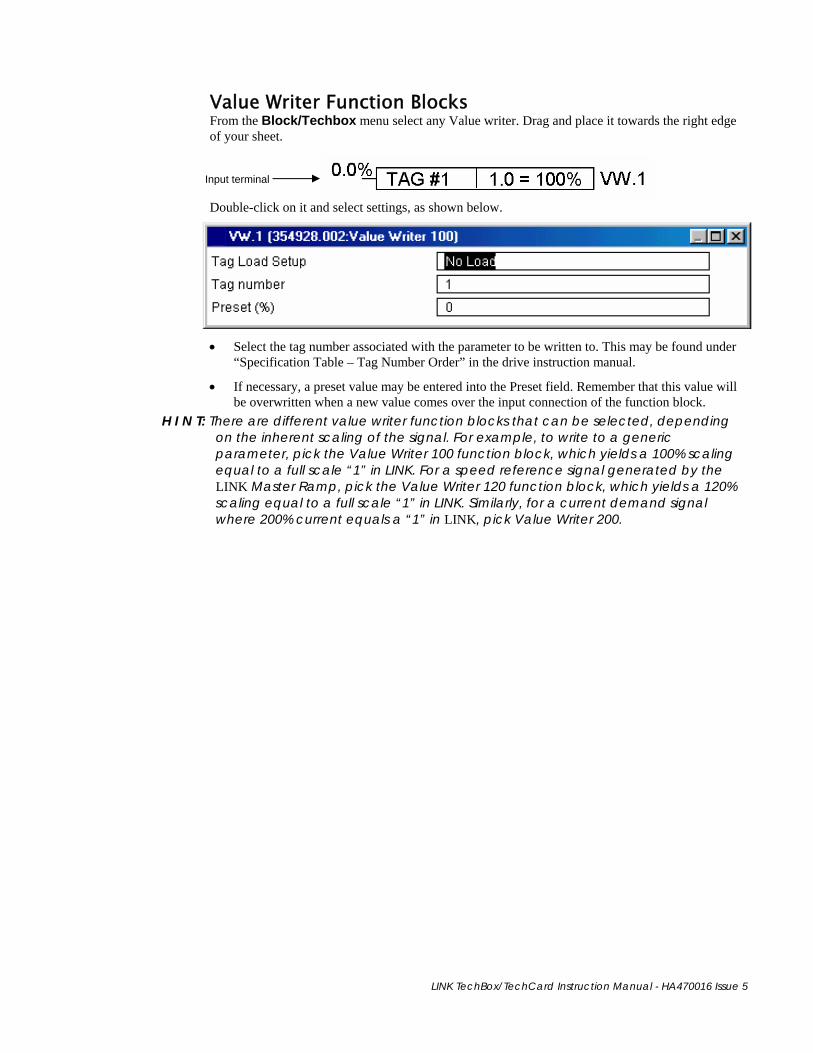
Value Writer Function Blocks From the Block/Techbox menu select any Value writer. Drag and place it towards the right edge of your sheet.
Double-click on it and select settings, as shown below.
• Select the tag number associated with the parameter to be written to. This may be found under “Specification Table – Tag Number Order” in the drive instruction manual.
• If necessary, a preset value may be entered into the Preset field. Remember that this value will be overwritten when a new value comes over the input connection of the function block.
H I N T: There are different value writer function blocks that can be selected, depending on the inherent scaling of the signal. For example, to write to a generic parameter, pick the Value Writer 100 function block, which yields a 100% scaling equal to a full scale “1” in LINK. For a speed reference signal generated by the LINK Master Ramp, pick the Value Writer 120 function block, which yields a 120% scaling equal to a full scale “1” in LINK. Similarly, for a current demand signal where 200% current equals a “1” in LINK, pick Value Writer 200.
Input terminal

39
LINK TechBox/TechCard Instruction Manual - HA470016 Issue 5
Notes

LINK TechBox/TechCard Instruction Manual - HA470016 Issue 5
*HA470016*
HA470016 LINK TechCard / TechBox
Singapore Parker Hannifin Singapore Pte Ltd 11, Fourth Chin Bee Rd 619702 Tel: +65 6887 6300 Fax: +65 6265 5125
Parker Hannifin (Espana) S.A. Parque Industrial Las Monjas Calle de las Estaciones 8 28850 Torrejonde Ardoz Madrid Tel: +34 91 6757300 Fax: +34 91 6757711
Spain
Parker Hannifin AB Montörgatan 7 SE-302 60 Halmstad Tel: +46(35)177300 Fax: +46(35)108407
Sweden
China Parker Hannifin Motion & Control (Shanghai) Co. Ltd. SSD Drives 280 Yunqiao Road Export Processing Zone Pudong District Shanghai 201206 P.R.China Tel: +86(21) 5031 2525 Fax: +86(21) 5854 7599
Parker Hannifin Ltd. Tachbrook Park Drive Tachbrook Park Warwick CV34 6TU Tel: +44(0)1926 317970 Fax: +44(0)1926 317980
UK
Parker Hannifin Corp. SSD Drives Division 9225 Forsyth Park Drive Charlotte NC 28273-3884 Tel: +1(704)588 3246 Fax: +1(704) 588-3249
Sales Offices
Australia Parker Hannifin Pty Ltd 9 Carrington Road Private Bag 4, Castle Hill NSW 1765 Tel: +61 2 9634 7777 Fax: +61 2 9899 6184
Belgium Parker Hannifin SA NV Parc Industriel Sud Zone 11 23, Rue du Bosquet Nivelles B -1400 Belgium Tel: +32 67 280 900 Fax: +32 67 280 999
Brazil Parker Hannifin Ind. e Com. Ltda. Av. Lucas Nogueira Garcez, 2181 Esperança - Caixa Postal 148 Tel: +55 0800 7275374 Fax: +55 12 3954 5262
Canada Parker Motion and Control 160 Chisolm Drive Milton Ontario L9T 3G9 Tel: +1(905)693 3000 Fax: +1(905)876 1958
France Parker SSD Parvex 8 Avenue du Lac B.P. 249 F-21007 Dijon Cedex Tel: +33 (0)3 80 42 41 40 Fax: +33 (0)3 80 42 41 23
Germany Parker Hannifin GmbH Von-Humboldt-Strasse 10 64646 Heppenheim Tel: +49(0)6252 798200 Fax: +49(0)6252 798205
India SSD Drives India Pvt Ltd 151 Developed Plots Estate Perungudi, Chennai, 600 O96 Tel: +91 44 43910799 Fax: +91 44 43910700
Italy Parker Hannifin SPA Via Gounod 1 20092 Cinisello Balsamo Milano Tel: +39 02 66012459 Fax: +39 02 66012808
www.parker.com www.ssddrives.com
© 2008 Parker Hannifin Corporation. All rights reserved.