link viewer
DESCRIPTION
sral linkviewer manualTRANSCRIPT
53-011A2-F00/EIssue 1, September 1999
SRA L
LOW CAPACITY DIGITAL RADIO SYSTEM
LINK VIEWER
OPERATING MANUAL (OMN)SOFTWARE RELEASE 1.9
ManualVolume: 1/1 code: 911-345/02A0190
Equipment code: Approved by:
Responsible for Instruction Manual Department
Signature: Date: �������
Manual printed:

SRA L LOW CAPACITY DIGITAL RADIO SYSTEM
LINK VIEWEROPERATING MANUAL (OMN)
SOFTWARE RELEASE 1.9Volume: 1/1 911-345/02A0190
D.45 D.55
D.25
D.30
D.20
SRA L
LOW CAPACITY DIGITAL RADIO SYSTEM
LINK VIEWER
OPERATING MANUAL (OMN)SOFTWARE RELEASE 1.9
Volume: 1/1 911-345/02A0190
SRA LLOW CAPACITY DIGITAL RADIO
SYSTEM
LINK VIEWER
OPERATING MANUAL (OMN)SOFTWARE RELEASE 1.9
Volume: 1/1 911-345/02A0190
SRA L
LOW CAPACITY DIGITAL RADIO SYSTEM
LINK VIEWER
OPERATING MANUAL (OMN)SOFTWARE RELEASE 1.9
Volume: 1/1 911-345/02A0190
SRA LLOW CAPACITY DIGITAL RADIO
SYSTEMLINK VIEWER
Volume: 1/1 911-345/02A0190SRA L
LOW CAPACITY DIGITAL RADIO SYSTEM
LINK VIEWEROPERATING MANUAL (OMN)
SOFTWARE RELEASE 1.9
Volume: 1/1 911-345/02A0190
OPERATING MANUAL (OMN)SOFTWARE RELEASE 1.9

SRA L - Link Viewer Handbook status
53-011A2-R00/EIssue 1, September 1999 1/2
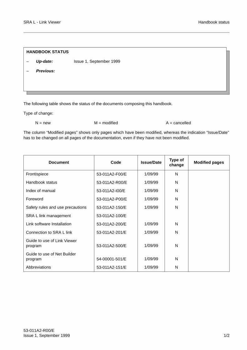
The following table shows the status of the documents composing this handbook.
Type of change:
N = new M = modified A = cancelled
The column “Modified pages” shows only pages which have been modified, whereas the indication “Issue/Date”has to be changed on all pages of the documentation, even if they have not been modified.
Document Code Issue/DateType of change
Modified pages
Frontispiece 53-011A2-F00/E 1/09/99 N
Handbook status 53-011A2-R00/E 1/09/99 N
Index of manual 53-011A2-I00/E 1/09/99 N
Foreword 53-011A2-P00/E 1/09/99 N
Safety rules and use precautions 53-011A2-150/E 1/09/99 N
SRA L link management 53-011A2-100/E
Link software Installation 53-011A2-200/E 1/09/99 N
Connection to SRA L link 53-011A2-201/E 1/09/99 N
Guide to use of Link Viewer program 53-011A2-500/E 1/09/99 N
Guide to use of Net Builder program 54-00001-501/E 1/09/99 N
Abbreviations 53-011A2-151/E 1/09/99 N
HANDBOOK STATUS
– Up-date: Issue 1, September 1999
– Previous:

Handbook status SRA L - Link Viewer
53-011A2-R00/E2/2 Issue 1, September 1999
FINE
BLANK PAGE
SRA L - Link Viewer Index
53-011A2-I00/EIssue 1, September 1999 1/2
Index of ManualFrontispiece 53-011A2-F00/E
Handbook status 53-011A2-R00/EIndex of manual 53-011A2-I00/E
Section 1: INTRODUCTION
Foreword 53-011A2-P00/E
Safety rules and use precautions 53-011A2-150/E
Section 2: OVERVIEW
SRA L link management 53-011A2-150/I
Section 3: SOFTWARE INSTALLATION
Link software Installation 53-011A2-200/E
Connection to SRA L link 53-011A2-201/E
Section 4: GUIDE TO USE OF SOFTWARE
Guide to use of Link Viewer program 53-011A2-500/EGuide to use of Net Builder program 53-00001-501/E
Section 5: ABBREVIATIONS
Abbreviations 53-011A2-151/E

Index SRA L - Link Viewer
53-011A2-I00/E2/2 Issue 1, September 1999
FINE
BLANK PAGE
SRA L - Link ViewerSRA L management system
Foreword
53-011A2-P00/EIssue 1, September 1999

Foreword SRA L - Link Viewer
53-011A2-P00/E2/8 Issue 1, September 1999
BLANK PAGE
SRA L - Link Viewer Foreword
53-011A2-P00/EIssue 1, September 1999 3/8
Contents
1 SUBJECT AND SCOPE OF THE MANUAL . . . . . . . . . . . . . . . . . . . . . . . . 5
2 CONTENTS . . . . . . . . . . . . . . . . . . . . . . . . . . . . . . . . . . . . . . . . . . . . . . . . . 7
3 TESTING AND WARRANTY . . . . . . . . . . . . . . . . . . . . . . . . . . . . . . . . . . . . 7
4 RESPONSIBILITY . . . . . . . . . . . . . . . . . . . . . . . . . . . . . . . . . . . . . . . . . . . . 7
5 DELIVERY . . . . . . . . . . . . . . . . . . . . . . . . . . . . . . . . . . . . . . . . . . . . . . . . . . 8
6 SRA L MANUALS . . . . . . . . . . . . . . . . . . . . . . . . . . . . . . . . . . . . . . . . . . . . 8
Foreword SRA L - Link Viewer
53-011A2-P00/E4/8 Issue 1, September 1999
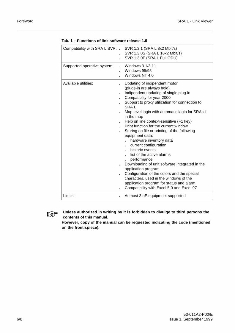
TablesTab. 1 Functions of link software release 1.9 . . . . . . . . . . . . . . . . . . . . . . . . . . . . . . 6
SRA L - Link Viewer Foreword
53-011A2-P00/EIssue 1, September 1999 5/8
1 SUBJECT AND SCOPE OF THE MANUAL
This OMN Manual provides the information required for SRA L link configuration andmanagement by means of the use of link software release 1.9 (code 559-013/76).The link software consists of the following programs:
– Link Viewer: this is program for SRA L link management.
– Net Builder: this is the program for the creation of the link maps which costitute thegraphical interface access the SRA L link.
– SuperTCP: this is the program providing the TCP/IP protocol and related utilities inWindows 3.1/3.11; the utilities can also be installed in Windows 95/NT if theoperator wants to work in graphical mode.It is necessary to install the SuperTCP program also in Windows 95/NT to execute,through FTP, the download of the unit software by remote (Controller unit,
Q-Adapter unit).
For every kind of SRA L, a specific plug-in software is provided, which makes theequipmnet control and configuration possible using Link Viewer.
Table 1 lists the functions of link software release 1.9.
Windows 95/NT uses the TCP/IP protocol provided b y the o peratin g systemitself.
For the modes of usin g the o perative menu, im plemented b y every plug-inSRA L, refer to the relative OMN Manual.
i
i
Foreword SRA L - Link Viewer
53-011A2-P00/E6/8 Issue 1, September 1999
Tab. 1 – Functions of link software release 1.9
Compatibility with SRA L SVR: . SVR 1.3.1 (SRA L 8x2 Mbit/s). SVR 1.3.0S (SRA L 16x2 Mbit/s). SVR 1.3.0F (SRA L Full ODU)
Supported operative system: . Windows 3.1/3.11. Windows 95/98. Windows NT 4.0
Available utilities: . Updating of indipendent motor(plugs-in are always hold)
. Indipendent updating of single plug-in
. Compatibilty for year 2000
. Support to proxy utilization for connection to SRA L
. Map-level login with automatic login for SRAs Lin the map
. Help on line context-sensitive (F1 key)
. Print function for the current window
. Storing on file or printing of the following equipment data:. hardware inventory data. current configuration. historic events. list of the active alarms. performance
. Downloading of unit software integrated in theapplication program
. Configuration of the colors and the specialcharacters, used in the windows of the application program for status and alarm
. Compatibility with Excel 5.0 and Excel 97
Limits: . At most 3 nE equipmnet supported
☞ Unless authorized in writin g by it is forbidden to divul ge to third persons thecontents of this manual.
However, co py of the manual can be re quested indicatin g the code (mentionedon the frontis piece).
SRA L - Link Viewer Foreword
53-011A2-P00/EIssue 1, September 1999 7/8
2 CONTENTS
This manual is subdivided into 5 sections:
– Section 1: Introduction
This section provides:• the information regarding the terms of delivery for the link software and the
Handbook• the safety precautions and regulations of use the personal must observe
when operating the equipment.
– Section 2: General information
This section provides the information required for correct management andconfiguration of the SRA L link.
– Section 3: Software installation
This section provides the information required for correct installation of linksoftware and for the connection to SRA L link.
– Section 4: Guide to use of software
This section provides the information required for the correct use of link software.
– Section 5: Abbreviations
This section summarizes all the abbreviations used in the figures and text of thisHandbook.
3 TESTING AND WARRANTY
Refer to the contract clauses for information regarding the subject matter.
4 RESPONSIBILITY
Refer to the contract clauses for information regarding the subject matter.Besides it is necessary to observe that:
– The manufacturer declines all responsibilities deriving from the incorrect or wronguse of the equipment, from the utilization of unauthorized parts and circuit,component and system software violations.
– The responsibility for the application of safety rules and use prescriptions isentrusted to the technical personnel responsible for the various activities, whichhas to make sure that the authorized personnel is qualified to perform therequested activity and has the required knowledge.
Foreword SRA L - Link Viewer
53-011A2-P00/E8/8 Issue 1, September 1999
5 DELIVERY
The link software release 1.9 (code 559-013/76) is provided on CD-ROM, equipped withrelevant serial numbers and passwords. The CD-ROM contents:
– the software (Link Viewer and Net Builder) to execute the SRA L link management(cof. 448-013/31); it is available as for Windows 3.1/3.11 as for Windows 95/NT
– the SuperTCP program (cod. 448-011/65).
– the set of SRA L software plug-in:• 8x2 Mbit/s SRA L plug-in (cod. 448-011/45)• Full ODUSRA L plug-in (cod. 448-011/46)
• 16x2 Mbit/s SRA L plug-in (cod. 448-011/47).
In case of installation on PC not provided with CD-ROM drive, it is possible to obtain thefloppy disks to install the programs and the olug-in from the relevant copy present onCD-ROM.
6 SRA L MANUALS
The following manuals are available for SRA L equipment:
– Installation Manual (ITMN)Contains the information required for equipment installation and commissioning.
– Operating Manual (OMN)Contains the information required for equipment use and maintenance.
– Hop Manager for PC (OMN)Contains the information required for configuration and control of the SRA L linkand related equipments by means of the service PC.
– Network Manager for PC (OMN)Contains the information required for configuration and control of the SRA Lnetwork and related equipments by means of the network PC.
All the manuals are available in the English language; they can be also provided in otherlanguages, depending on the contract clauses.FINE
The set of SRA L plug-in (cod. 559-011/45) can be provided requeseted also onspecific CD-ROM.i
SRA L - Link ViewerSystem for SRA L management
Safety rules and use precautions
53-011A2-150/EIssue 1, September 1999

Safety rules and use precautions SRA L - Link Viewer
53-011A2-150/E2/4 Issue 1, September 1999
BLANK PAGE
SRA L - Link Viewer Safety rules and use precautions
53-011A2-150/EIssue 1, September 1999 3/4
Contents
1 OVERVIEW . . . . . . . . . . . . . . . . . . . . . . . . . . . . . . . . . . . . . . . . . . . . . . . . . 4
Safety rules and use precautions SRA L - Link Viewer
53-011A2-150/E4/4 Issue 1, September 1999
1 OVERVIEW
Using the Link Viewer program, SRA L equipment operation is supposed to becontrolled by PC only.Using the application program for the management in Net Viewer/Link Viewer, it isassumed that the operation of SRA L equipment is controlled exclusively from the PC.This means that hardware-related safety precautions are not required. For any othertype of operation, the safety precautions contained in the ITMN Manual must beobserved.
FINE
SRA L - Link ViewerLow capacity digital radio system
Link management
53-011A2-100/EIssue 1, September 1999

Link management SRA L - Link Viewer
53-011A2-100/E2/46 Issue 1, September 1999
BLANK PAGE
SRA L - Link Viewer Link management
53-011A2-100/EIssue 1, September 1999 3/46
Contents
1 INTRODUCTION . . . . . . . . . . . . . . . . . . . . . . . . . . . . . . . . . . . . . . . . . . . . . 6
2 ADDRESS FORMAT FOR TCP/IP PROTOCOL . . . . . . . . . . . . . . . . . . . . . 72.1 Host and router . . . . . . . . . . . . . . . . . . . . . . . . . . . . . . . . . . . . . . . . . . . . . . . 72.2 IP address classification . . . . . . . . . . . . . . . . . . . . . . . . . . . . . . . . . . . . . . . . 72.3 Decimal notation of the IP address . . . . . . . . . . . . . . . . . . . . . . . . . . . . . . . . 82.4 Net-Mask. . . . . . . . . . . . . . . . . . . . . . . . . . . . . . . . . . . . . . . . . . . . . . . . . . . . 92.5 Reserved address values . . . . . . . . . . . . . . . . . . . . . . . . . . . . . . . . . . . . . . 10
3 SRA L LINK . . . . . . . . . . . . . . . . . . . . . . . . . . . . . . . . . . . . . . . . . . . . . . . . 123.1 SRA L link structure . . . . . . . . . . . . . . . . . . . . . . . . . . . . . . . . . . . . . . . . . . 123.2 Routing functions of the SRA L. . . . . . . . . . . . . . . . . . . . . . . . . . . . . . . . . . 143.3 Routing tables . . . . . . . . . . . . . . . . . . . . . . . . . . . . . . . . . . . . . . . . . . . . . . . 163.4 Host table . . . . . . . . . . . . . . . . . . . . . . . . . . . . . . . . . . . . . . . . . . . . . . . . . . 163.5 SRA L communication channels . . . . . . . . . . . . . . . . . . . . . . . . . . . . . . . . . 17
4 PROTOCOL STACK FOR SRA L LINK . . . . . . . . . . . . . . . . . . . . . . . . . . . 19
5 TCP/IP PROTOCOL OF THE SERVICE PC . . . . . . . . . . . . . . . . . . . . . . . 22
6 LINK MANAGEMENT SOFTWARE . . . . . . . . . . . . . . . . . . . . . . . . . . . . . . 23
7 AUXILIARY UTILITIES . . . . . . . . . . . . . . . . . . . . . . . . . . . . . . . . . . . . . . . 24
8 CONNECTION WITH A TMN SUPERVISION SYSTEM . . . . . . . . . . . . . . 25
9 PLANNING AND CONFIGURATION OF A SRA L LINK . . . . . . . . . . . . . . 289.1 Planning of IP addresses . . . . . . . . . . . . . . . . . . . . . . . . . . . . . . . . . . . . . . 289.2 Creation of the link map . . . . . . . . . . . . . . . . . . . . . . . . . . . . . . . . . . . . . . . 299.3 Configuration of SRA L link parameters . . . . . . . . . . . . . . . . . . . . . . . . . . . 309.4 Creation of the host table . . . . . . . . . . . . . . . . . . . . . . . . . . . . . . . . . . . . . . 329.5 Testing of the SRA L link . . . . . . . . . . . . . . . . . . . . . . . . . . . . . . . . . . . . . . 32
10 VALIDITY CONDITIONS OF TCP/IP PARAMETERS . . . . . . . . . . . . . . . . 3310.1 General . . . . . . . . . . . . . . . . . . . . . . . . . . . . . . . . . . . . . . . . . . . . . . . . . . . . 3310.2 Validity conditions for IP addresses and Net-Mask. . . . . . . . . . . . . . . . . . . 3310.2.1 IP addresses . . . . . . . . . . . . . . . . . . . . . . . . . . . . . . . . . . . . . . . . . . . . . . . . 3310.2.2 Net-Mask. . . . . . . . . . . . . . . . . . . . . . . . . . . . . . . . . . . . . . . . . . . . . . . . . . . 3510.2.3 IP address - Net-Mask combinations . . . . . . . . . . . . . . . . . . . . . . . . . . . . . 3710.3 Validity conditions for parameters of the static routing table. . . . . . . . . . . . 3810.4 Validity conditions for the F interface parameters (PC) . . . . . . . . . . . . . . . 3910.5 Reset of the TCP/IP parameters. . . . . . . . . . . . . . . . . . . . . . . . . . . . . . . . . 39
11 EXAMPLES OF SRA L LINK . . . . . . . . . . . . . . . . . . . . . . . . . . . . . . . . . . . 40
12 MAIN PROBLEMS OCCURRING IN THE SRA L LINK MANAGEMENT . 4412.1 Common problems in Windows 3.1/3.11 and Windows 95/NT. . . . . . . . . . 4412.2 Common problems in Windows 95/NT . . . . . . . . . . . . . . . . . . . . . . . . . . . . 44
13 BIBLIOGRAPHY . . . . . . . . . . . . . . . . . . . . . . . . . . . . . . . . . . . . . . . . . . . . 45
Link management SRA L - Link Viewer
53-011A2-100/E4/46 Issue 1, September 1999
IllustrationsFig. 1 Structure of IP addresses . . . . . . . . . . . . . . . . . . . . . . . . . . . . . . . . . . . . . . . 8
Fig. 2 Example of Net-Mask for Class B IP address . . . . . . . . . . . . . . . . . . . . . . . 10
Fig. 3 SRA L link structure . . . . . . . . . . . . . . . . . . . . . . . . . . . . . . . . . . . . . . . . . . . 13
Fig. 4 SRA L link structure with Add/Drop repeater . . . . . . . . . . . . . . . . . . . . . . . . 13
Fig. 5 Example of routing strategy in a SRA L link. . . . . . . . . . . . . . . . . . . . . . . . . 15
Fig. 6 Routing architecture of the SRA L . . . . . . . . . . . . . . . . . . . . . . . . . . . . . . . . 15
Fig. 7 SRA L communication channels for the transmission of management
and supervision information . . . . . . . . . . . . . . . . . . . . . . . . . . . . . . . . . . . . . 18
Fig. 8 TCP/IP protocol stack . . . . . . . . . . . . . . . . . . . . . . . . . . . . . . . . . . . . . . . . . 20
Fig. 9 TCP/IP protocol stack for SRA L link . . . . . . . . . . . . . . . . . . . . . . . . . . . . . . 21
Fig. 10 Connection configurations to the TMN supervision system . . . . . . . . . . . . . 26
Fig. 11 Local link between the Q-Adapter unit and the Controller units of the
station SRA Ls . . . . . . . . . . . . . . . . . . . . . . . . . . . . . . . . . . . . . . . . . . . . . . . 27
Fig. 12 Stack of standard Qx/Q3 protocol . . . . . . . . . . . . . . . . . . . . . . . . . . . . . . . . 27
Fig. 13 Example of a stand-alone SRA L link. . . . . . . . . . . . . . . . . . . . . . . . . . . . . . 41
Fig. 14 Example of a Intranet type SRA L link . . . . . . . . . . . . . . . . . . . . . . . . . . . . . 42
Fig. 15 Example of a Internet SRA L link . . . . . . . . . . . . . . . . . . . . . . . . . . . . . . . . . 43
SRA L - Link Viewer Link management
53-011A2-100/EIssue 1, September 1999 5/46
TablasTab. 1 Characteristics of IP addresses . . . . . . . . . . . . . . . . . . . . . . . . . . . . . . . . . . 9
Tab. 2 Reserved and available Internet addresses . . . . . . . . . . . . . . . . . . . . . . . . 11
Tab. 3 TCP/IP protocol of the service PC . . . . . . . . . . . . . . . . . . . . . . . . . . . . . . . 22
Link management SRA L - Link Viewer
53-011A2-100/E6/46 Issue 1, September 1999
1 INTRODUCTION
This document provides the link administrator with useful information regardingconfiguration and management of a SRA L link, i.e. a system based on TCP/IP protocol,normally used in Internet an Intraned network type.The following are detailed descriptions of:
– the main addressing and routing characteristics of TCP/IP networks
– the main characteristics of the TCP/IP protocol used in SRA L link and of thededicated software for the link administrator
– the main characteristics of the connection to a TMN supervision system
– the guidelines for the planning and configuration of a SRA L link.
For general concepts and detailed information regarding the protocol and TCP/IPnetworks please refer to specific documentation in par. 13 ("Bibliography").
Link management SRA L - Link Viewer
53-011A2-100/E7/46 Issue 1, September 1999
2 ADDRESS FORMAT FOR TCP/IP PROTOCOL
2.1 Host and router
Network devices for the TCP/IP protocol are subdivided into:
– Host: device for an application that responds to the TCP/IP protocol
– Router (or gateway): device that manages routing information for various networklines.
The SRA L is a device that can function both as a host and a router.
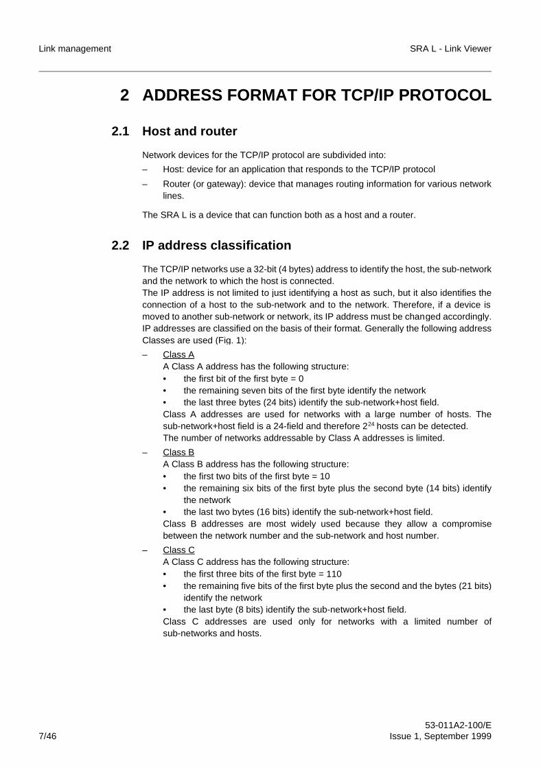
2.2 IP address classification
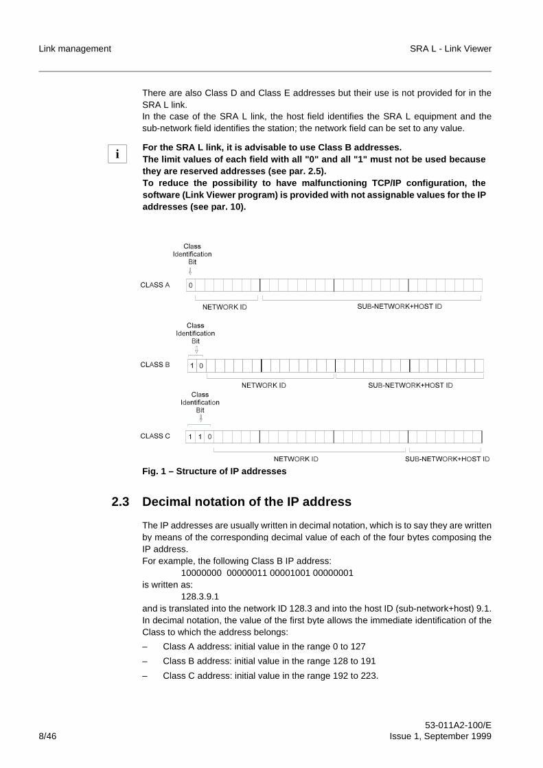
The TCP/IP networks use a 32-bit (4 bytes) address to identify the host, the sub-networkand the network to which the host is connected.The IP address is not limited to just identifying a host as such, but it also identifies theconnection of a host to the sub-network and to the network. Therefore, if a device ismoved to another sub-network or network, its IP address must be changed accordingly.IP addresses are classified on the basis of their format. Generally the following addressClasses are used (Fig. 1):
– Class AA Class A address has the following structure:• the first bit of the first byte = 0• the remaining seven bits of the first byte identify the network• the last three bytes (24 bits) identify the sub-network+host field.Class A addresses are used for networks with a large number of hosts. Thesub-network+host field is a 24-field and therefore 224 hosts can be detected.The number of networks addressable by Class A addresses is limited.
– Class BA Class B address has the following structure:• the first two bits of the first byte = 10• the remaining six bits of the first byte plus the second byte (14 bits) identify
the network• the last two bytes (16 bits) identify the sub-network+host field.Class B addresses are most widely used because they allow a compromisebetween the network number and the sub-network and host number.
– Class CA Class C address has the following structure:• the first three bits of the first byte = 110• the remaining five bits of the first byte plus the second and the bytes (21 bits)
identify the network• the last byte (8 bits) identify the sub-network+host field.Class C addresses are used only for networks with a limited number ofsub-networks and hosts.
Link management SRA L - Link Viewer
53-011A2-100/E8/46 Issue 1, September 1999
There are also Class D and Class E addresses but their use is not provided for in theSRA L link.In the case of the SRA L link, the host field identifies the SRA L equipment and thesub-network field identifies the station; the network field can be set to any value.
Fig. 1 – Structure of IP addresses
2.3 Decimal notation of the IP address
The IP addresses are usually written in decimal notation, which is to say they are writtenby means of the corresponding decimal value of each of the four bytes composing theIP address.For example, the following Class B IP address:
10000000 00000011 00001001 00000001is written as:
128.3.9.1and is translated into the network ID 128.3 and into the host ID (sub-network+host) 9.1.In decimal notation, the value of the first byte allows the immediate identification of theClass to which the address belongs:
– Class A address: initial value in the range 0 to 127
– Class B address: initial value in the range 128 to 191
– Class C address: initial value in the range 192 to 223.
For the SRA L link, it is advisable to use Class B addresses.The limit values of each field with all "0" and all "1" must not be used becausethey are reserved addresses (see par. 2.5).To reduce the possibility to have malfunctioning TCP/IP configuration, thesoftware (Link Viewer program) is provided with not assignable values for the IPaddresses (see par. 10).
i
Link management SRA L - Link Viewer
53-011A2-100/E9/46 Issue 1, September 1999
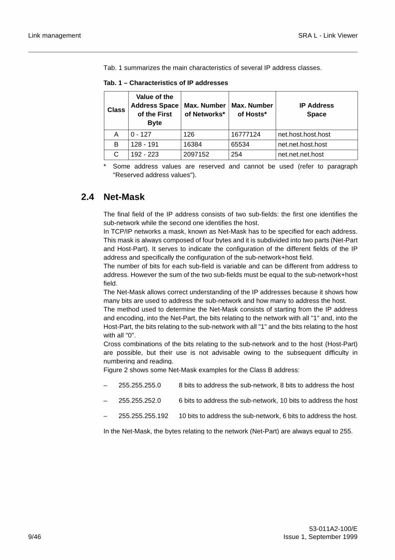
Tab. 1 summarizes the main characteristics of several IP address classes.
Tab. 1 – Characteristics of IP addresses
* Some address values are reserved and cannot be used (refer to paragraph"Reserved address values").
2.4 Net-Mask
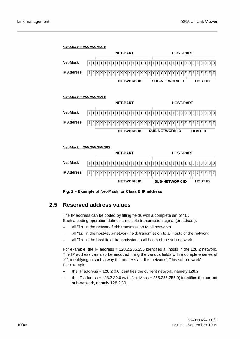
The final field of the IP address consists of two sub-fields: the first one identifies thesub-network while the second one identifies the host.In TCP/IP networks a mask, known as Net-Mask has to be specified for each address.This mask is always composed of four bytes and it is subdivided into two parts (Net-Partand Host-Part). It serves to indicate the configuration of the different fields of the IPaddress and specifically the configuration of the sub-network+host field.The number of bits for each sub-field is variable and can be different from address toaddress. However the sum of the two sub-fields must be equal to the sub-network+hostfield.The Net-Mask allows correct understanding of the IP addresses because it shows howmany bits are used to address the sub-network and how many to address the host.The method used to determine the Net-Mask consists of starting from the IP addressand encoding, into the Net-Part, the bits relating to the network with all "1" and, into theHost-Part, the bits relating to the sub-network with all "1" and the bits relating to the hostwith all "0".Cross combinations of the bits relating to the sub-network and to the host (Host-Part)are possible, but their use is not advisable owing to the subsequent difficulty innumbering and reading.Figure 2 shows some Net-Mask examples for the Class B address:
– 255.255.255.0 8 bits to address the sub-network, 8 bits to address the host
– 255.255.252.0 6 bits to address the sub-network, 10 bits to address the host
– 255.255.255.192 10 bits to address the sub-network, 6 bits to address the host.
In the Net-Mask, the bytes relating to the network (Net-Part) are always equal to 255.
Class
Value of theAddress Space
of the First Byte
Max. Numberof Networks*
Max. Numberof Hosts*
IP AddressSpace
A 0 - 127 126 16777124 net.host.host.host
B 128 - 191 16384 65534 net.net.host.host
C 192 - 223 2097152 254 net.net.net.host
Link management SRA L - Link Viewer
53-011A2-100/E10/46 Issue 1, September 1999
Fig. 2 – Example of Net-Mask for Class B IP address
2.5 Reserved address values
The IP address can be coded by filling fields with a complete set of "1".Such a coding operation defines a multiple transmission signal (broadcast):
– all "1s" in the network field: transmission to all networks
– all "1s" in the host+sub-network field: transmission to all hosts of the network
– all "1s" in the host field: transmission to all hosts of the sub-network.
For example, the IP address = 128.2.255.255 identifies all hosts in the 128.2 network.The IP address can also be encoded filling the various fields with a complete series of"0", identifying in such a way the address as "this network", "this sub-network".For example:
– the IP address = 128.2.0.0 identifies the current network, namely 128.2
– the IP address = 128.2.30.0 (with Net-Mask = 255.255.255.0) identifies the currentsub-network, namely 128.2.30.
1 1 1 1 1 1 1 1 1 1 1 1 1 1 1 1 1 1 1 1 1 1 1 1 0 0 0 0 0 0 0 0
1 0 X X X X X X X X X X X X X X Y Y Y Y Y Y Y Y Z Z Z Z Z Z Z Z
Net-Mask = 255.255.255.0
Net-Mask
IP Address
NETWORK ID SUB-NETWORK ID HOST ID
NET-PART HOST-PART
1 1 1 1 1 1 1 1 1 1 1 1 1 1 1 1 1 1 1 1 1 1 0 0 0 0 0 0 0 0 0 0
1 0 X X X X X X X X X X X X X X Y Y Y Y Y Y Z Z Z Z Z Z Z Z Z Z
Net-Mask = 255.255.252.0
Net-Mask
IP Address
NETWORK ID SUB-NETWORK ID HOST ID
NET-PART HOST-PART
1 1 1 1 1 1 1 1 1 1 1 1 1 1 1 1 1 1 1 1 1 1 1 1 1 1 0 0 0 0 0 0
1 0 X X X X X X X X X X X X X X Y Y Y Y Y Y Y Y Y Y Z Z Z Z Z Z
Net-Mask = 255.255.255.192
Net-Mask
IP Address
NETWORK ID SUB-NETWORK ID HOST ID
NET-PART HOST-PART
SRA L - Link Viewer Link management
53-011A2-100/EIssue 1, September 1999 11/46
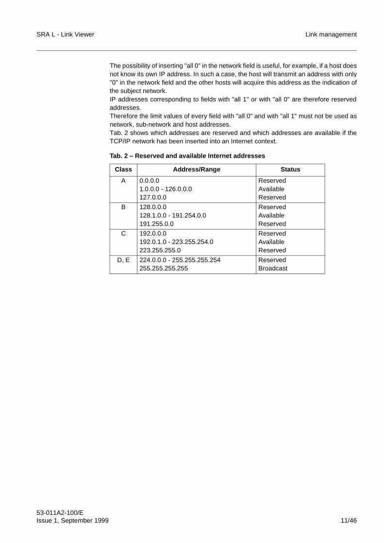
The possibility of inserting "all 0" in the network field is useful, for example, if a host doesnot know its own IP address. In such a case, the host will transmit an address with only"0" in the network field and the other hosts will acquire this address as the indication ofthe subject network.IP addresses corresponding to fields with "all 1" or with "all 0" are therefore reservedaddresses.Therefore the limit values of every field with "all 0" and with "all 1" must not be used asnetwork, sub-network and host addresses.Tab. 2 shows which addresses are reserved and which addresses are available if theTCP/IP network has been inserted into an Internet context.
Tab. 2 – Reserved and available Internet addresses
Class Address/Range Status
A 0.0.0.01.0.0.0 - 126.0.0.0127.0.0.0
ReservedAvailableReserved
B 128.0.0.0128.1.0.0 - 191.254.0.0191.255.0.0
ReservedAvailableReserved
C 192.0.0.0192.0.1.0 - 223.255.254.0223.255.255.0
ReservedAvailableReserved
D, E 224.0.0.0 - 255.255.255.254255.255.255.255
ReservedBroadcast
Link management SRA L - Link Viewer
53-011A2-100/E12/46 Issue 1, September 1999
3 SRA L LINK
3.1 SRA L link structure
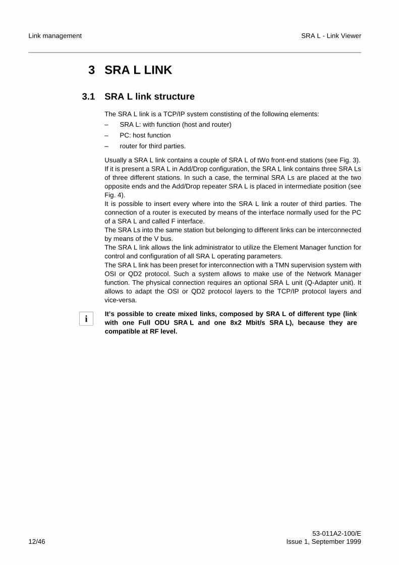
The SRA L link is a TCP/IP system constisting of the following elements:
– SRA L: with function (host and router)
– PC: host function
– router for third parties.
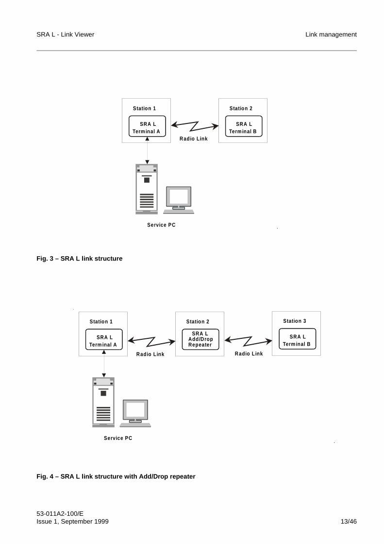
Usually a SRA L link contains a couple of SRA L of tWo front-end stations (see Fig. 3).If it is present a SRA L in Add/Drop configuration, the SRA L link contains three SRA Lsof three different stations. In such a case, the terminal SRA Ls are placed at the twoopposite ends and the Add/Drop repeater SRA L is placed in intermediate position (seeFig. 4).It is possible to insert every where into the SRA L link a router of third parties. Theconnection of a router is executed by means of the interface normally used for the PCof a SRA L and called F interface.The SRA Ls into the same station but belonging to different links can be interconnectedby means of the V bus.The SRA L link allows the link administrator to utilize the Element Manager function forcontrol and configuration of all SRA L operating parameters.The SRA L link has been preset for interconnection with a TMN supervision system withOSI or QD2 protocol. Such a system allows to make use of the Network Managerfunction. The physical connection requires an optional SRA L unit (Q-Adapter unit). Itallows to adapt the OSI or QD2 protocol layers to the TCP/IP protocol layers andvice-versa.
It’s possible to create mixed links, composed by SRA L of different type (linkwith one Full ODU SRA L and one 8x2 Mbit/s SRA L), because they arecompatible at RF level.
i
SRA L - Link Viewer Link management
53-011A2-100/EIssue 1, September 1999 13/46
Fig. 3 – SRA L link structure
Fig. 4 – SRA L link structure with Add/Drop repeater
Station 2
Term inal B
Service PC
Station 1
Term inal ASRA L SRA L
Radio Link
�
�
Station 3
Term inal BSRA L
Station 1
Term inal ASRA L
Station 2
Add/Dro pSRA L
Rep eater
Service PC
Radio L ink Radio L ink
�
�
Link management SRA L - Link Viewer
53-011A2-100/E14/46 Issue 1, September 1999
3.2 Routing functions of the SRA L
Every SRA L is a device with dual function: the host and the router. This feature ispossible because the SRA L is able to identify the destination (the SRA L itself, anotherSRA L, a router, a PC) on the basis of the IP address and consequently to route themessage towards the proper path.As a router, the SRA L is capable of branching the signal over different routes:
– toward its own circuits; in this case the SRA L behaves a host
– toward a local PC or router, through serial line (F interface)
– toward a SRA L of the same station, through LAN (V bus)
– toward a SRA L of another station, through radio (R and D channels).
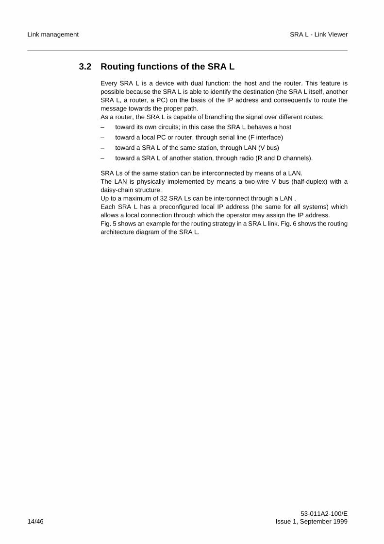
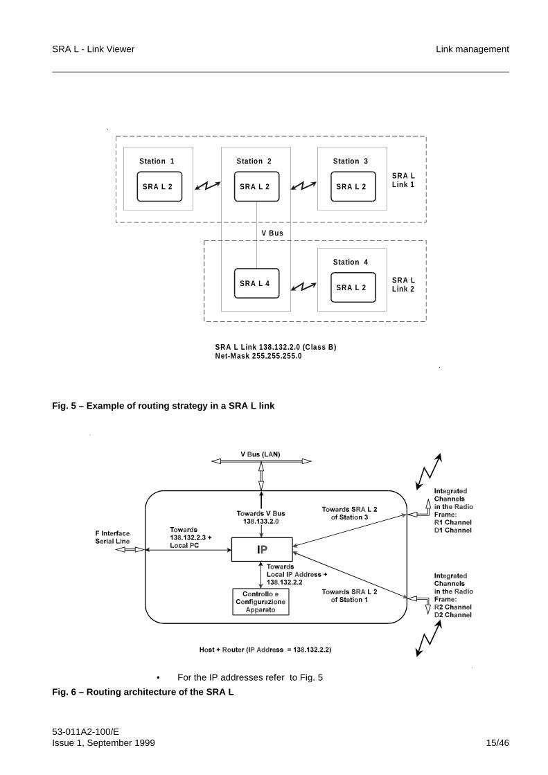
SRA Ls of the same station can be interconnected by means of a LAN.The LAN is physically implemented by means a two-wire V bus (half-duplex) with adaisy-chain structure.Up to a maximum of 32 SRA Ls can be interconnect through a LAN .Each SRA L has a preconfigured local IP address (the same for all systems) whichallows a local connection through which the operator may assign the IP address.Fig. 5 shows an example for the routing strategy in a SRA L link. Fig. 6 shows the routingarchitecture diagram of the SRA L.
SRA L - Link Viewer Link management
53-011A2-100/EIssue 1, September 1999 15/46
Fig. 5 – Example of routing strategy in a SRA L link
• For the IP addresses refer to Fig. 5
Fig. 6 – Routing architecture of the SRA L
Station 4
SRA L Link 138.132.2.0 (C lass B )Net-Mask 255.255.255.0
SRA L 2
Station 1
SRA L 2
Station 2
V Bus
SRA L 2
Station 3
SRA L 2
SRA LLink 2
SRA L 4
SRA LLink 1
�
�
Link management SRA L - Link Viewer
53-011A2-100/E16/46 Issue 1, September 1999
3.3 Routing tables
In a TCP/IP network, element with router function manages the routing according torouting tables which specify the parameters for every possible route. The routing tablescan be of two different types:
– Static routing tables: These tables are defined by the network administrator and arefixed in advance. In case of network expansion or change they have to be updated.
– Dynamic routing tables: These tables are generated by the various networkelements with router function on the basis of to the information acquired by thenetwork. In case of network expansion or change these tables are automaticallyupdated by means of a routing protocol.
For this purpose the SRA L supports the RIP protocol version 1. Consequently, everySRA L is able, depending on information acquired from the link, to obtain a completeoverview of the link structure. Dynamic routing tables are created automatically,enabling the SRA L to define a routing over the most suitable path.In the presence of expansion, change or failure/interruption of the SRA L link, eachSRA L automatically updates the corresponding dynamic routing tables, thus adaptingthe tables to the new SRA L link structure.
Static routing tables are required if routers not supporting the RIP protocol are usedinside the SRA L link.A specific routing table can be created to exit from the SRA L link, which via the RIPprotocol is recognized by all SRA Ls as the default outlet of the SRA L link.
3.4 Host table
The creation and use of a host table on the service PC, allows to associate a mnemonicacronym with each SRA L which can be used instead of the numeric IP address.In the host table, the correspondence between mnemonic acronyms and numeric IPaddresses must be specified for all hosts in the link.The host table can be dynamically defined by means of DNS, if a device with thisfunction is connected to the SRA L link.The procedure for creation of the host table is described in the document "Installation oflink software".
☞ The RIP protocol version 1 re quires the same Net-Mask in the entire the SRA Llink.
SRA L - Link Viewer Link management
53-011A2-100/EIssue 1, September 1999 17/46
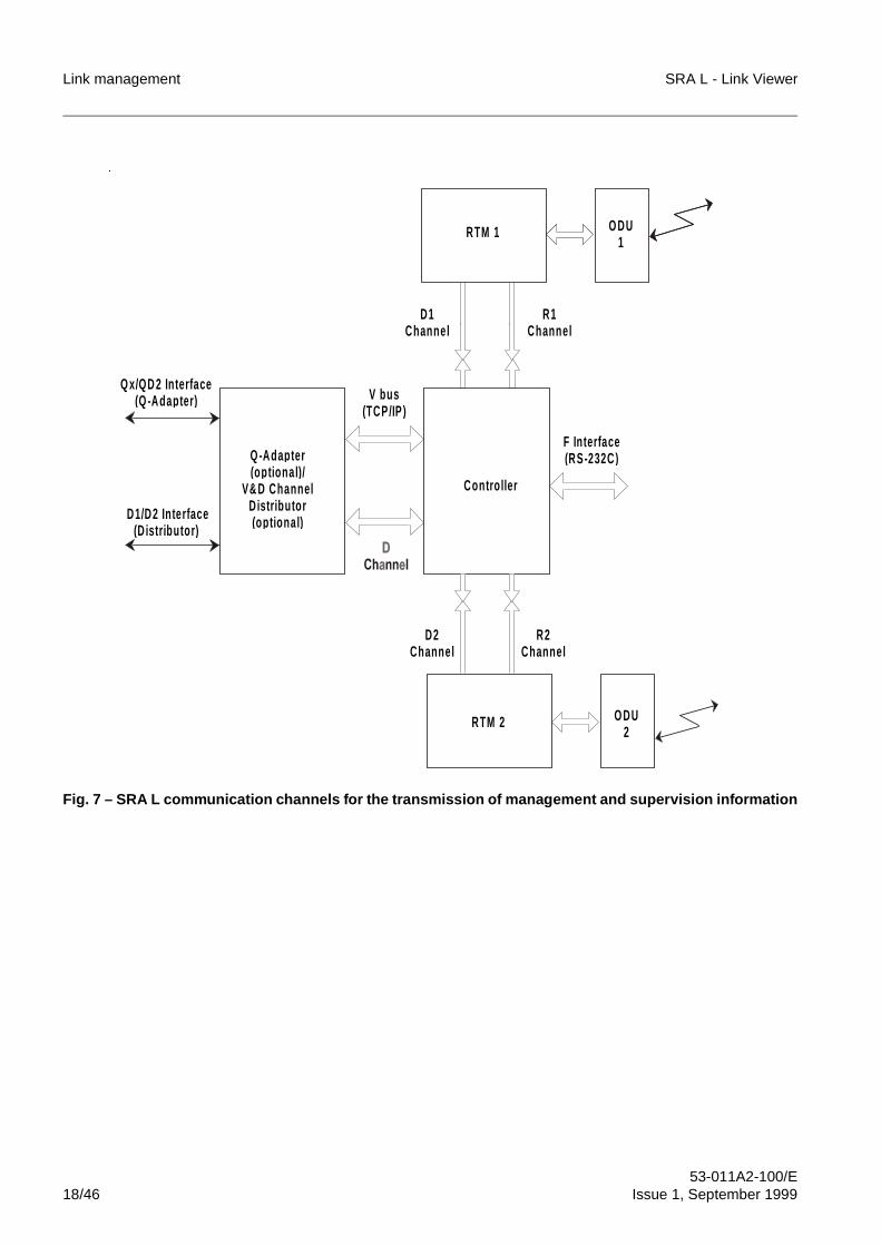
3.5 SRA L communication channels
Several communication channels are used in SRA L, for the transmission of SRA L linkmanagement and supervision information:
– Integrated channel R1/R2The integrated R channel is a 64 kbit/s synchronous data channel with TCP/IPprotocol.It is a reserved channel in the radio frame and is used for the transmission ofmanagement information between two SRA Ls of two different stations via radio.In case of SRA L with 2x(1+0) and A/D-RPT configuration, there are two differentintegrated channels (R1 and R2).In case of SRA L with (1+1) configuration, the two channels R1 and R2 are used inprotected mode; the redundancy is managed by SRA L hardware.
– PC channel (F interface)The PC channel is a 19.2 kbit/s asynchronous data channel (RS-232C standard).It is used for transmission of management information between the SRA L and aPC or a router through a serial line.The connection with the PC channel can be realized by means of a modem.
– V busThe V bus is a 128 kbit/s data bus with burst mode (HDLC frame) and TCP/IPprotocol.It is used for the transmission of management information between SRA Ls of thesame station.
– Q channelThe Q channel is used for the transmission of management information betweenthe SRA L and a TMN supervision system.The Q channel is available with two different protocols, depending on the type ofsupervision system:• QD2: connection to Access Integrator or other QD2 managers• Ethernet (10BASE2): connection to EM-OS with standard OSI protocol.The Q channel is present if the SRA L is equipped with the Q-Adapter unit.
– D1/D2 channelThe D channel is a 64 kbit/s synchronous data channel with TCP/IP protocol. It isa reserved channel of the radio frame and it is used for the transmission of the TMNsupervision information on one slot of the 2 Mbit/s tributary stream (slot andtributary are programmable).In such a way the supervision information can cross different transmission systems(e.g.: optical fibre systems) and reach other SRA L links/networks.In case of SRA L in 2x(1+0) and A/D-RPT configuration, there are two independentD1 and D2 channels. In case of SRA L in (1+1) configuration, the two channels areused with protected mode and the SRA L hardware manages the redundancy.In case of equipment provided with V&D Channel Distributor unit, the D1 and D2channels are available at connector, for the possible connection towards othertransmission systems; in such a way the supervision information (TCP/IP) canreach SRA L links/networks.
Fig. 7 shows the communication channels available in the SRA L.
Link management SRA L - Link Viewer
53-011A2-100/E18/46 Issue 1, September 1999
Fig. 7 – SRA L communication channels for the transmission of management and supervision information
V bus(TCP/IP )
Q -Ada p ter(o p tional )/
V& D ChannelD istributor(o p tional )
RTM 1 O DU1
Contro ller
RTM 2 O DU2
F In terface(RS-232C)
R1Channel
D1Channel
R2Channel
D2Channel
D1/D2 In terface(D istributor )
Q x/QD 2 In terface(Q -Ada p ter )
�
SRA L - Link Viewer Link management
53-011A2-100/EIssue 1, September 1999 19/46
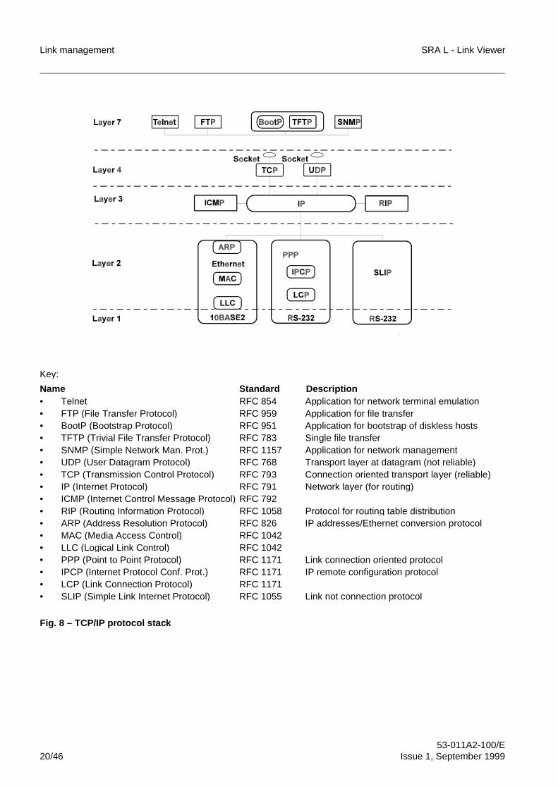
4 PROTOCOL STACK FOR SRA L LINK
The TCP/IP protocol is a layered protocol, consisting of:
– Application layer
– Transport layer
– Network layer
– Data connection and physical connection layer.
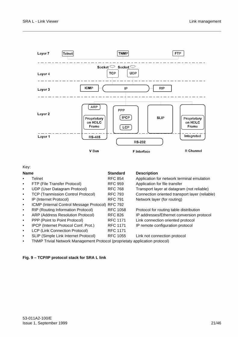
The TCP/IP protocol stack is shown in Fig. 8.Fig. 9 shows the TCP/IP protocol stack used in SRA L link.
Link management SRA L - Link Viewer
53-011A2-100/E20/46 Issue 1, September 1999
Key:
Name Standard Description • Telnet RFC 854 Application for network terminal emulation• FTP (File Transfer Protocol) RFC 959 Application for file transfer• BootP (Bootstrap Protocol) RFC 951 Application for bootstrap of diskless hosts• TFTP (Trivial File Transfer Protocol) RFC 783 Single file transfer• SNMP (Simple Network Man. Prot.) RFC 1157 Application for network management• UDP (User Datagram Protocol) RFC 768 Transport layer at datagram (not reliable)• TCP (Transmission Control Protocol) RFC 793 Connection oriented transport layer (reliable)• IP (Internet Protocol) RFC 791 Network layer (for routing)• ICMP (Internet Control Message Protocol) RFC 792• RIP (Routing Information Protocol) RFC 1058 Protocol for routing table distribution• ARP (Address Resolution Protocol) RFC 826 IP addresses/Ethernet conversion protocol• MAC (Media Access Control) RFC 1042• LLC (Logical Link Control) RFC 1042• PPP (Point to Point Protocol) RFC 1171 Link connection oriented protocol• IPCP (Internet Protocol Conf. Prot.) RFC 1171 IP remote configuration protocol• LCP (Link Connection Protocol) RFC 1171• SLIP (Simple Link Internet Protocol) RFC 1055 Link not connection protocol
Fig. 8 – TCP/IP protocol stack
SRA L - Link Viewer Link management
53-011A2-100/EIssue 1, September 1999 21/46
Key:
Name Standard Description • Telnet RFC 854 Application for network terminal emulation• FTP (File Transfer Protocol) RFC 959 Application for file transfer• UDP (User Datagram Protocol) RFC 768 Transport layer at datagram (not reliable)• TCP (Tranmission Control Protocol) RFC 793 Connection oriented transport layer (reliable)• IP (Internet Protocol) RFC 791 Network layer (for routing)• ICMP (Internal Control Message Protocol) RFC 792• RIP (Routing Information Protocol) RFC 1058 Protocol for routing table distribution• ARP (Address Resolution Protocol) RFC 826 IP addresses/Ethernet conversion protocol• PPP (Point to Point Protocol) RFC 1171 Link connection oriented protocol• IPCP (Internet Protocol Conf. Prot.) RFC 1171 IP remote configuration protocol• LCP (Link Connection Protocol) RFC 1171• SLIP (Simple Link Internet Protocol) RFC 1055 Link not connection protocol• TNMP Trivial Network Management Protocol (proprietaty application protocol)
Fig. 9 – TCP/IP protocol stack for SRA L link
Link management SRA L - Link Viewer
53-011A2-100/E22/46 Issue 1, September 1999
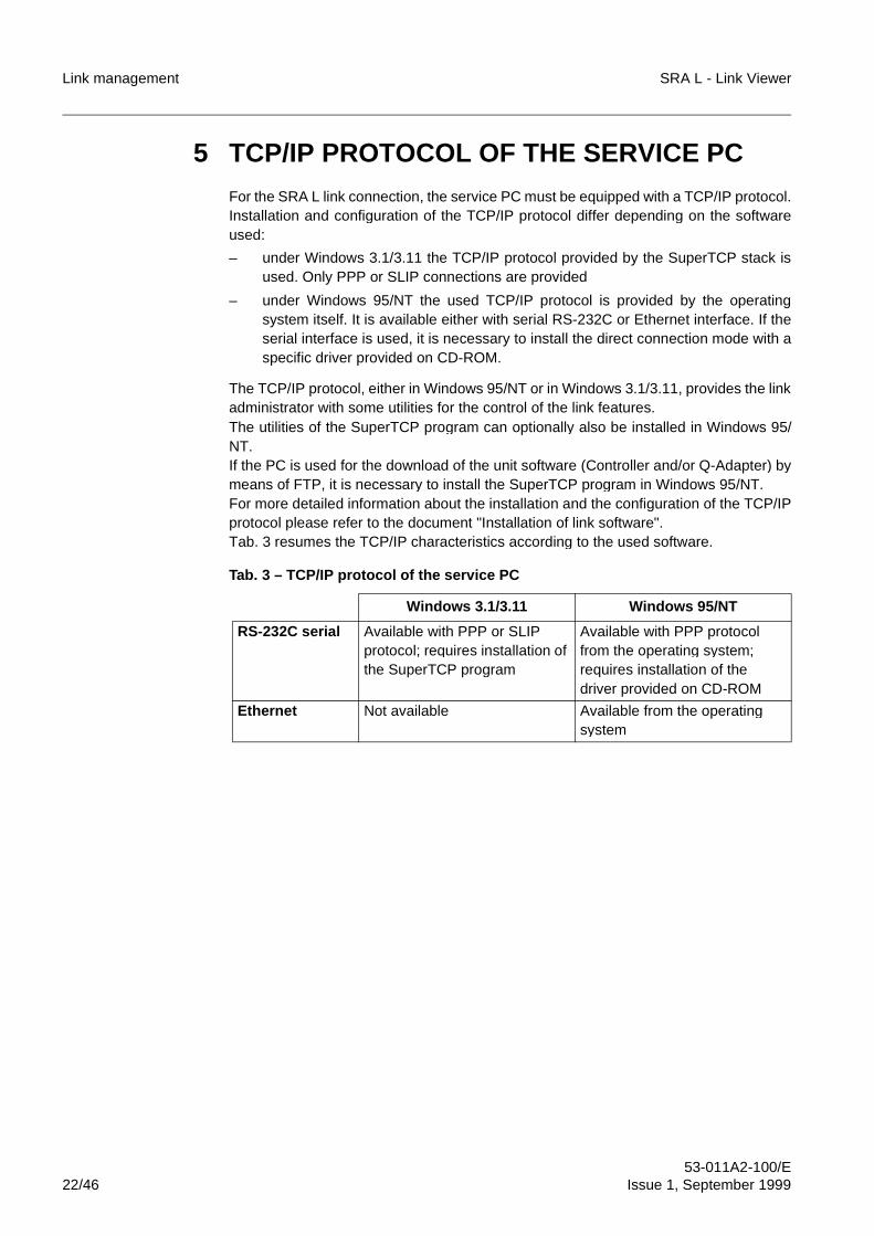
5 TCP/IP PROTOCOL OF THE SERVICE PC
For the SRA L link connection, the service PC must be equipped with a TCP/IP protocol.Installation and configuration of the TCP/IP protocol differ depending on the softwareused:
– under Windows 3.1/3.11 the TCP/IP protocol provided by the SuperTCP stack isused. Only PPP or SLIP connections are provided
– under Windows 95/NT the used TCP/IP protocol is provided by the operatingsystem itself. It is available either with serial RS-232C or Ethernet interface. If theserial interface is used, it is necessary to install the direct connection mode with aspecific driver provided on CD-ROM.
The TCP/IP protocol, either in Windows 95/NT or in Windows 3.1/3.11, provides the linkadministrator with some utilities for the control of the link features.The utilities of the SuperTCP program can optionally also be installed in Windows 95/NT.If the PC is used for the download of the unit software (Controller and/or Q-Adapter) bymeans of FTP, it is necessary to install the SuperTCP program in Windows 95/NT.For more detailed information about the installation and the configuration of the TCP/IPprotocol please refer to the document "Installation of link software".Tab. 3 resumes the TCP/IP characteristics according to the used software.
Tab. 3 – TCP/IP protocol of the service PC
Windows 3.1/3.11 Windows 95/NT
RS-232C serial Available with PPP or SLIP protocol; requires installation of the SuperTCP program
Available with PPP protocol from the operating system; requires installation of the driver provided on CD-ROM
Ethernet Not available Available from the operating system
SRA L - Link Viewer Link management
53-011A2-100/EIssue 1, September 1999 23/46
6 LINK MANAGEMENT SOFTWARE
The SRA L link management software provided for the link administrator consists of twoapplication programs for Windows which are available on CD-ROM:
– Link Viewer programThis program allows to configure the SRA L link and to manage control andconfiguration of all SRA Ls in the network. For SRA L link configuration, theprogram allows the configuration of parameters TCP/IP and static tables for everySRA L. If a TMN system with OSI/QD2 protocol is connected, the program alsoallows to configure the TMN connection parameters for SRA L which act as a
gateway. This program is intended for normal operators.
– Net Builder programThis program allows to create the link map. These maps constitute the graphicalinterface of the Link Viewer program for connection to the SRA L. This program isintended for link administrators.
The programs are available both for Windows 3.1/3.11 and Windows 95/NT.For more detailed information regarding the operating modes of the programs pleaserefer to the documents "Guide to use of Link Viewer program" and "Guide to use of NetBuilder program".
For every Kind of SRA L, a specific plug-in software is provided, which makesthe equipment control and configuration possible, using Link Viewer.i
Link management SRA L - Link Viewer
53-011A2-100/E24/46 Issue 1, September 1999
7 AUXILIARY UTILITIES
The link administrator can use the software utilities of the TCP/IP protocol to check theSRA L link features.The TCP/IP protocol of the Windows 95/NT operating system makes the followingutilities available as DOS commands:
– PingIt is possible to send a ping command towards a host in order to verify if the TCP/IP stack of the addressed host is visible and to measure the transmission time inthe go and return direction.
– NetStatThis is a typical Windows 95/NT utility which allows to call statistics all active TCP/IP connections.
– TraceRTIt is possible to send a TraceRT command towards a host in order to verify if thepath to reach the addressed host is the intended path and is free from failures and/or conflicts.
– RouteIt allows managing the local TCP/IP routing table (route). In particular, the "PRINT"option allows the displaying of the entire routing table.
– Ipconfig (only for Windows NT)It allows checking the configuration of the PC interfaces that use the TCP/IPprotocol.
In Windows 95, the Winipcfg utility with graphical mode is available: it has the samefunctions of the Ipconfig utility used in Windows NT.The optional TelNet utility with graphical mode is available in Windows 95/NT. Such autility allows opening a virtual terminal in the TCP/IP stack of the specified host.Similar software utilities with graphical mode are provided in Windows 3.1/3.11 by theSuperTCP program.If the operator wants to work with graphical mode utilities instead of DOS commandmodes, the utilities of the SuperTCP program can also be installed in Windows 95/NT.The SuperTCP program, then, makes available as in Windows 3.1/3.11 as in Windows95/NT the FTP Client and FTP Server utilities.Such utilities allow the download procedure from remote of the software of the Controllerunits (FTP Client) and of the Q-Adapter units (FTP server).
SRA L - Link Viewer Link management
53-011A2-100/EIssue 1, September 1999 25/46
8 CONNECTION WITH A TMN SUPERVISIONSYSTEM
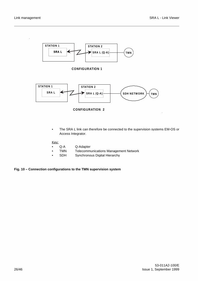
The connection feature between SRA L link and TMN supervision system (EM-OS) isrealised by the Q-Adapter unit. Such a unit provides the translation between TCP/IPprotocol (SRA L link) and standard Qx/Q3 protocol (TMN supervision system).A number of different configurations are possible (refer to Fig. 10):
– Configuration 1: Q-Adapter unit connected directly to the supervision system
– Configuration 2: Q-Adapter connected to the supervision system through the SDHnetwork.
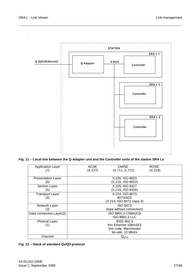
An Ethernet (ISO 8802.3) interface is used, to connect Q-Adapter unit to EM-OS .As an alternative, the Q-Adapter unit allows connection of the SRA L link to the AccessIntegrator supervision system or other QD2 managers by means of the QD2 interface.The Q-Adapter unit is connected to the controller of the same SRA L and to thecontrollers of other SRA Ls in the station through the V bus (refer to Fig. 11).Full ODU SRA L is not equipped with the Q-Adapter unit. However, a Full ODU SRA Lcan be supervisioned by a TMN system, using the Q-Adapter unit of another SRA L forthe connection (8x2 Mbit/s SRA L or 16x2 Mbit/s SRA L) The following cases arepossible:
– mixed link, the last one is equipped with the Q-Adapter unit
– connection between a Full ODU STA L to another SRA L in the station, via V bus.The second SRA L is equipped with the Q-Adapter unit.
Fig. 12 shows the stack of the standard Qx/Q3 protocol.
Link management SRA L - Link Viewer
53-011A2-100/E26/46 Issue 1, September 1999
• The SRA L link can therefore be connected to the supervision systems EM-OS orAccess Integrator.
Key:• Q-A Q-Adapter• TMN Telecommunications Management Network• SDH Synchronous Digital Hierarchy
Fig. 10 – Connection configurations to the TMN supervision system
STATIO N 1 STATIO N 2
TMN
STATIO N 2
TMN
SDH NETW O RK
SRA LSRA L
STATIO N 1
SRA L (Q-A)SRA LSRA L
SRA L (Q-A)
CONFIGURATION 2
CONFIGURATION 1
SRA L
SRA L
�
�
SRA L - Link Viewer Link management
53-011A2-100/EIssue 1, September 1999 27/46
Fig. 11 – Local link between the Q-Adapter unit and the Controller units of the station SRA Ls
Fig. 12 – Stack of standard Qx/Q3 protocol
Application Layer(7)
ACSE CMISE ROSE(X.227) (X.711, X.712) (X.229)
Presentation Layer(6)
X.226, ISO 8823(X.216, ISO 8822)
Section Layer(5)
X.225, ISO 8327(X.215, ISO 8326)
Transport Layer(4)
X.224, ISO 80738073/AD2
(X.214, ISO 8072 class 4)Network Layer
(3)ISO 8473
(type without connection)Data connection Layer(2) ISO 8802.3 CSMA/CD
ISO 8802.2 LLCPhisical Layer
(1)IEEE 802.3
thin Ethernet 10BASE2line code: Manchester
bit-rate: 10 Mbit/sChannel QETH
SRA L 1
SRA L 3
SRA L 2
V BUSQ (QD2/Ethernet)
STATIO N
Q -AdapterContro ller
Contro ller
Contro ller
�
Link management SRA L - Link Viewer
53-011A2-100/E28/46 Issue 1, September 1999
9 PLANNING AND CONFIGURATION OF ASRA L LINK
9.1 Planning of IP addresses
For the assignment of IP addresses for the SRA L link, the link administrator has toproceed as follows.
1. Choose the IP address type to be used for the SRA L link:• Class A• Class B• Class C.If Class A is selected, please note that the last 2 bytes of the IP address of all theSRA L systems on a single V bus must be different, because they are used as MACaddresses (see Fig. 8) on the same bus.
2. Assign the network ID of the IP address. During the assignment of the network ID,pay attention to the current SRA L link type.• stand-alone type SRA L link: it is possible to use any network ID.• Intranet type SRA L link: it is necessary to use a network ID that has not been
yet assigned, otherwise, there will be conflicts and routing failures betweenthe interconnected networks.
• Internet type SRA L link: it is necessary to request the IP address assignmentfrom the authorised entity (IANA).
3. Assign the Net-Mask; it must be unique for all the SRA L link to define how manybits, of the sub-network + host of the IP addresses field, have to be used for thesub-network addressing (station) and hor many for the host addressing (SRA L orservice PC).
4. Identify every station with its relevant IP address, assigning the sub-network ID ofthe IP addresses.
5. Identify every SRA L with its relevant IP address, assigning the host ID of the IPaddress, follow the rules listed below:
• Addresses with fields coded with "all-1" and "all-0", must not be used for asingle link element because they are reserved addresses of a TCP/IPnetwork.
• Every station LAN can contain up to a maximum of 32 SRA Ls and hence canseize up to 64 different IP addresses (32 IP addresses for the SRA L + 32 IPaddresses for the corresponding F interface).
• With Q-Adapter unit equipped, it is necessary to assign an IP address also tothe V interface of the unit itself.
The TCP/IP parameter validity conditions (see par. 10), of the software (LinkViewer program), has to be considered when the configuration and planning ofthe SRA L link has to be carried out.
For the SRA L link, it is advisable to use Class B addresses.
i
i
SRA L - Link Viewer Link management
53-011A2-100/EIssue 1, September 1999 29/46
6. Define the static routing tables.Static routing tables are strictly required for SRA Ls connected to routers notsupporting the RIP protocol.The information contained in the static routing table of a specific SRA L can beacquired via RIP protocol, also from all other SRA Ls in the link.
7. Define, if desired, the host table in such a manner as to associate a mnemonicacronym with every IP address in order to facilitate the operator’s task in locatingand identifying the various SRA Ls in the link. For a detailed description of theprocedure for drawing up a host table, please refer to the document "Installation oflink software".
9.2 Creation of the link map
The link map constitutes the necessary graphical interface for connection to the SRA Lwhen the link management software is used.To create the maps, it is necessary to use the proper Net Builder program. Such aprogram has the following features:
– If it is desired to have a graphical link layout as background, it is possible to importa drawing of the SRA L link in ".BMP" format.
– Positioning of SRA L icons in pre-arranged positions.
– Assignation of the relevant IP address to each SRA L. During definition of the hosttable, it is possible to use mnemonic acronyms instead of numeric IP addresses.
– Saving the created map in ".MAP" file format with the desired name.
In addition, the program allows modification of the pre-existing maps.A map is also required for connection to the local SRA L. The software is delivered witha standard map for connection to the local SRA L .To realise the SRA L link drawing one of the graphical application programs in Windowsmust be used (either in Windows 3.1/3.11 or in Windows 95/NT) which supports thegraphical ".BMP" format (e.g.: Paintbrush).The SRA L link drawing can be of any type, for example:
– a geographic map pointing out location of the various stations
– a block-diagram pointing out all link interconnections.
☞ The SRA L IP addresses have to be assigned in steps of two because for everySRA L an IP address corresponding to the F interface (service PC or router) isautomatically added. Such an address is equal to the SRA L IP address plus one;e.g. in case of Net-Mask = 255.255.255.0:• SRA L IP address = 150.166.32.2• SRA L F interface IP address = 150.166.32.3.It is advisable to follow a systematic rule such as using only even IP addressesfor the SRA L.
☞ An incorrect settin g in a static table can cause a wron g routin g of mana gementinformation into the link and hence ma y endan ger operation of the whole SRA Llink.
Link management SRA L - Link Viewer
53-011A2-100/E30/46 Issue 1, September 1999
When creating the drawing please be careful to leave enough space in the various SRAL positions to allow for future positioning of the respective icons in order to end up witha clear and neat map. For help on how to use the Net Builder program please refer tothe document "Guide to use of Net Builder program".
9.3 Configuration of SRA L link parameters
Once the link plan is defined all link parameters must be assigned to the SRA Lequipment, taking into account the validity conditions provided by the software (refer topar. 10).
The following link parameters can be set through software:
– Equipment IP address and the corresponding Net-Mask (the same Net-Mask forthe entire SRA L link), according to the planning of the IP addresses of the SRA Llink.
– F interface parameters:• Communication protocol: PPP or SLIP. Preferably, always set the PPP
protocol. The SLIP protocol should be used only if the PC hardware does notsupport the PPP protocol. The PPP protocol allows the service PC to detectthe IP address assigned to the F interface automatically. On the contrary, ifthe SLIP protocol is used, it is necessary to set the IP address manually onthe service PC before connecting it to the SRA L.
• Baud-rate: 9600 bps or 19200 bps. Preferably, always set 19200 bps; 9600bps should be used only if the PC hardware does not support a baud-rate of19200 bps.
– Static routing table, if necessary. It is possible to set up to a maximum of threedifferent routings for each SRA L. For every routing it is necessary to specify thefollowing data:• the SRA L interface for which the routing is defined: F interface, V bus,
integrated R1 channel, integrated R2 channel (not available in (1+0) and(1+1) configurations)
• the network IP address and destination gateway address.
– Q-Adapter unit parameters (if installed):• IP address and relevant Net-Mask of the V interface for the connection
towards SRA L link, according to the IP address planning of the SRA L link.• IP address and relevant Net-Mask of the Ethernet interface for the connection
towards supervision system. Such parameters must be assigned by theadministrator of the used network to communicate with the supervisionsystem.
☞ When the settin g of SRA L link parameters is performed for the first time, it isnecessar y to isolate the SRA L itself be from the rest of the link. Otherwiseconflicts ma y occur in the link.
☞ The setting of the gateway IP address is only necessary in case of routing on aV bus, because on the V bus it is necessary to specify the SRA L of destinationwhile this is optional in other cases.In a SRA L link only a single default routing can be set (multiple transmission toall networks). To assign the default routing, set the IP address = 0.0.0.0.
SRA L - Link Viewer Link management
53-011A2-100/EIssue 1, September 1999 31/46
• OSI/QD2 address of the Qx/QD2 interface. Such address must be assignedby the administrator of the supervision system.
– D channel Add/Drop on the 2 Mbit/s tributary streams (if it is necessary). It ispossible enable the D channel Add/Drop operation on 2 Mbit/s tributary streams,
selecting the tributary and the relevant slot to be used.
For help on how to use the Link Viewer program refer to the "Guide to use of Link Viewerprogram".
In case of SRA L in 2x(1+0) and A/D-RPT configuration, there are twoindependent D channels.The D channel setting is necessary only on the SRA Ls acting as branchingpoints towards other systems.
i
Link management SRA L - Link Viewer
53-011A2-100/E32/46 Issue 1, September 1999
9.4 Creation of the host table
The creation mode of the host table is different depending on to the operating system ofthe service PC (see doc. “Installation of link software”):
– Windows 95/NTIn the "hosts" file, placed in the Windows 95/NT system directory (typically"c:\windows"), it is necessary to specify the correspondence between the SRA Lnumeric IP address and the corresponding mnemonic acronym. To open and editthe "hosts" file use an editor program. The file has to be saved in ASCII formatwithout any extensions in such a way that Windows 95/NT can detect it as a systemfile.
– Windows 3.11/3.11The special menu SetupTCP of the SuperTCP software must be used to specifythe correspondence between the SRA L numeric IP address and the relevantmnemonic acronym.
9.5 Testing of the SRA L link
After execution of the planning and configuration procedure of the SRA L link, the linkadministrator has to carry out, by means of the software utilities of the TCP/IP protocol,its testing to check that:1. There are no conflicts on the link.2. All SRA Ls can be reached and answer the connection request.3. All possible routes of the link are free of routing errors.
For more detailed information about the use of the software utilities refer to the Windows95/NT handbooks.
SRA L - Link Viewer Link management
53-011A2-100/EIssue 1, September 1999 33/46
10 VALIDITY CONDITIONS OF TCP/IPPARAMETERS
10.1 General
The TCP/IP parameters that can be configured via software are the following ones:
– IP address of the SRA L and relevant Net-Mask
– static routing table
– connection parameters between SRA L and PC (F interface).
To minimize the possible presence fo malfunctioning TCP/IP configurations, thesoftware (Link Viewer program) provides some values that can not be assigned for eachsome values that can not be assigned for each TCP/IP parameter.The detection for each parameters of the validity conditions and of the not validity onesis based upon the RFC standards and upon the SRA L particular structure.The validity and not validity condition for the IP addresses and the Net-Masks contentsalso the combinations between the two parameters. In fact some values, considered asvalid if they are singularly taken into account, can define, if they are combined, some notvalid sub-network or host values.The setting of a not valid value is signalled by the software on the video through anegative answer like "out of range".Then it is provided a reset mode of the TCP/IP parameters.
10.2 Validity conditions for IP addresses and Net-Mask
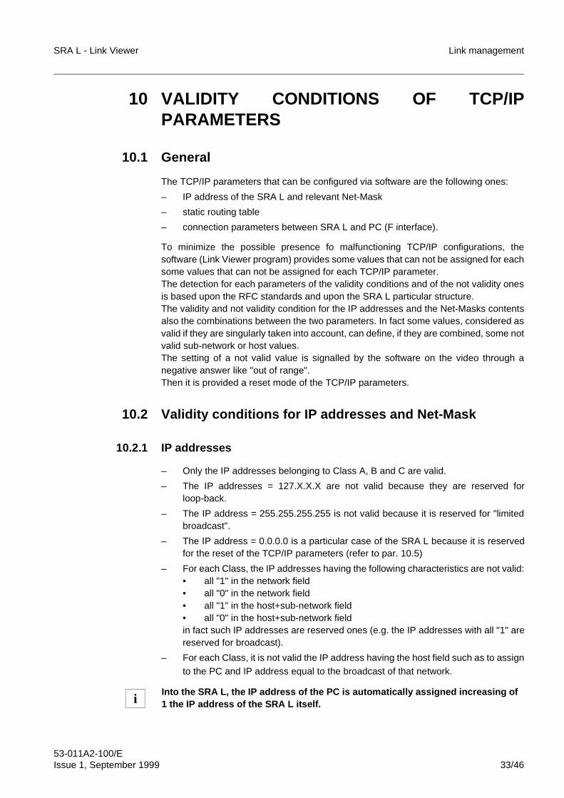
10.2.1 IP addresses
– Only the IP addresses belonging to Class A, B and C are valid.
– The IP addresses = 127.X.X.X are not valid because they are reserved forloop-back.
– The IP address = 255.255.255.255 is not valid because it is reserved for "limitedbroadcast".
– The IP address = 0.0.0.0 is a particular case of the SRA L because it is reservedfor the reset of the TCP/IP parameters (refer to par. 10.5)
– For each Class, the IP addresses having the following characteristics are not valid:• all "1" in the network field• all "0" in the network field• all "1" in the host+sub-network field• all "0" in the host+sub-network fieldin fact such IP addresses are reserved ones (e.g. the IP addresses with all "1" arereserved for broadcast).
– For each Class, it is not valid the IP address having the host field such as to assignto the PC and IP address equal to the broadcast of that network.
Into the SRA L, the IP address of the PC is automatically assigned increasing of1 the IP address of the SRA L itself.i
Link management SRA L - Link Viewer
53-011A2-100/E34/46 Issue 1, September 1999
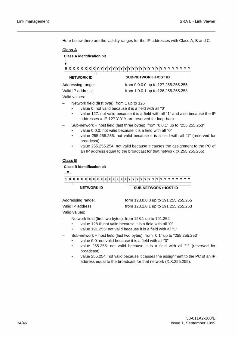
Here below there are the validity ranges for the IP addresses with Class A, B and C.
Class A
Addressing range: from 0.0.0.0 up to 127.255.255.255
Valid IP address: from 1.0.0.1 up to 126.255.255.253
Valid values:
– Network field (first byte): from 1 up to 126• value 0: not valid because it is a field with all "0"• value 127: not valid because it is a field with all "1" and also because the IP
addresses = IP 127.Y.Y.Y are reserved for loop-back
– Sub-network + host field (last three bytes): from "0.0.1" up to "255.255.253"• value 0.0.0: not valid because it is a field with all "0"• value 255.255.255: not valid because it is a field with all "1" (reserved for
broadcast)• value 255.255.254: not valid because it causes the assignment to the PC of
an IP address equal to the broadcast for that network (X.255.255.255).
Class B
Addressing range: form 128.0.0.0 up to 191.255.255.255
Valid IP address: from 128.1.0.1 up to 191.255.255.253
Valid values:
– Network field (first two bytes): from 128.1 up to 191.254• value 128.0: not valid because it is a field with all "0"• value 191.255: not valid because it is a field with all "1"
– Sub-network + host field (last two bytes): from "0.1" up to "255.255.253"• value 0.0: not valid because it is a field with all "0"• value 255.255: not valid because it is a field with all "1" (reserved for
broadcast)• value 255.254: not valid because it causes the assignment to the PC of an IP
address equal to the broadcast for that network (X.X.255.255).
0 X X X X X X X Y Y Y Y Y Y Y Y Y Y Y Y Y Y Y Y Y Y Y Y Y Y Y Y
Class A identification bit
NETWORK ID SUB-NETWORK+HOST ID
1 0 X X X X X X X X X X X X X X Y Y Y Y Y Y Y Y Y Y Y Y Y Y Y Y
Class B identification bit
NETWORK ID SUB-NETWORK+HOST ID
SRA L - Link Viewer Link management
53-011A2-100/EIssue 1, September 1999 35/46
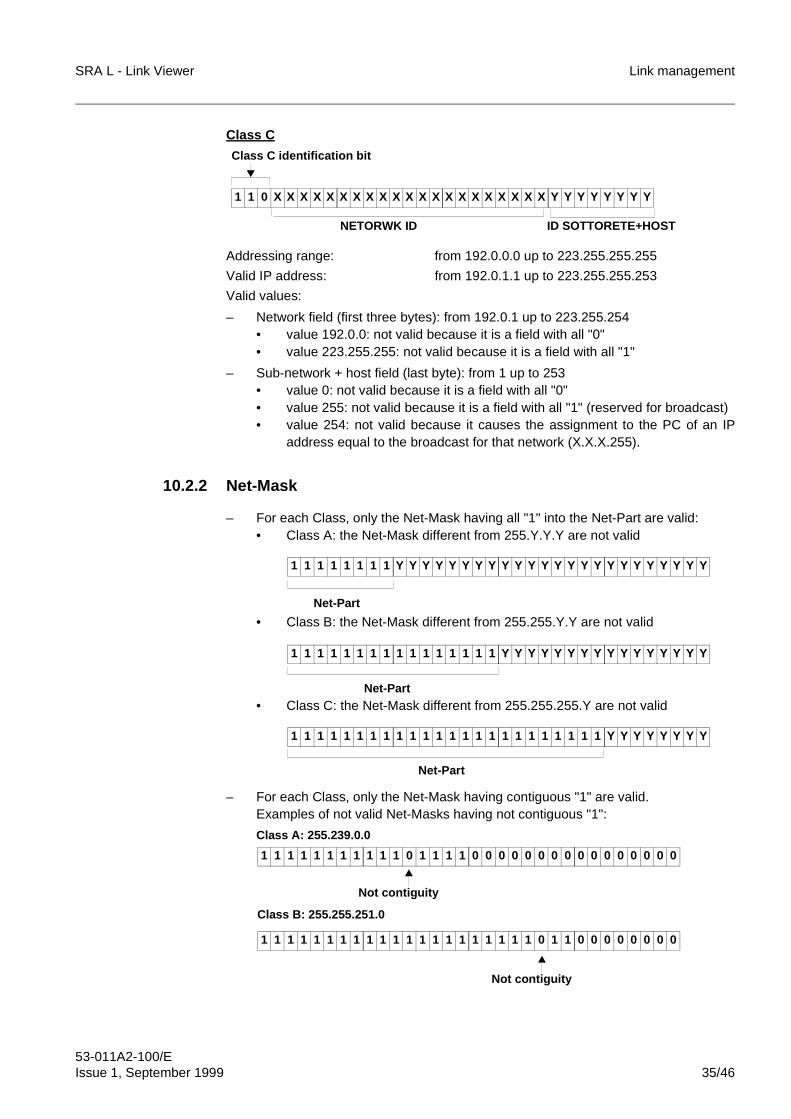
Class C
Addressing range: from 192.0.0.0 up to 223.255.255.255
Valid IP address: from 192.0.1.1 up to 223.255.255.253
Valid values:
– Network field (first three bytes): from 192.0.1 up to 223.255.254• value 192.0.0: not valid because it is a field with all "0"• value 223.255.255: not valid because it is a field with all "1"
– Sub-network + host field (last byte): from 1 up to 253• value 0: not valid because it is a field with all "0"• value 255: not valid because it is a field with all "1" (reserved for broadcast)• value 254: not valid because it causes the assignment to the PC of an IP
address equal to the broadcast for that network (X.X.X.255).
10.2.2 Net-Mask
– For each Class, only the Net-Mask having all "1" into the Net-Part are valid:• Class A: the Net-Mask different from 255.Y.Y.Y are not valid
• Class B: the Net-Mask different from 255.255.Y.Y are not valid
• Class C: the Net-Mask different from 255.255.255.Y are not valid
– For each Class, only the Net-Mask having contiguous "1" are valid.Examples of not valid Net-Masks having not contiguous "1":
1 1 0 X X X X X X X X X X X X X X X X X X X X X Y Y Y Y Y Y Y Y
Class C identification bit
NETORWK ID ID SOTTORETE+HOST
1 1 1 1 1 1 1 1 Y Y Y Y Y Y Y Y Y Y Y Y Y Y Y Y Y Y Y Y Y Y Y Y
Net-Part
1 1 1 1 1 1 1 1 1 1 1 1 1 1 1 1 Y Y Y Y Y Y Y Y Y Y Y Y Y Y Y Y
Net-Part
1 1 1 1 1 1 1 1 1 1 1 1 1 1 1 1 1 1 1 1 1 1 1 1 Y Y Y Y Y Y Y Y
Net-Part
1 1 1 1 1 1 1 1 1 1 1 0 1 1 1 1 0 0 0 0 0 0 0 0 0 0 0 0 0 0 0 0
Not contiguity
Class A: 255.239.0.0
1 1 1 1 1 1 1 1 1 1 1 1 1 1 1 1 1 1 1 1 1 0 1 1 0 0 0 0 0 0 0 0
Not contiguity
Class B: 255.255.251.0
Link management SRA L - Link Viewer
53-011A2-100/E36/46 Issue 1, September 1999
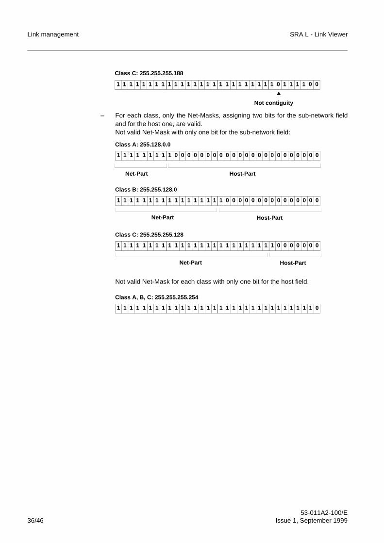
– For each class, only the Net-Masks, assigning two bits for the sub-network fieldand for the host one, are valid.Not valid Net-Mask with only one bit for the sub-network field:
Not valid Net-Mask for each class with only one bit for the host field.
1 1 1 1 1 1 1 1 1 1 1 1 1 1 1 1 1 1 1 1 1 1 1 1 1 0 1 1 1 1 0 0
Not contiguity
Class C: 255.255.255.188
1 1 1 1 1 1 1 1 1 0 0 0 0 0 0 0 0 0 0 0 0 0 0 0 0 0 0 0 0 0 0 0
Class A: 255.128.0.0
Net-Part Host-Part
1 1 1 1 1 1 1 1 1 1 1 1 1 1 1 1 1 0 0 0 0 0 0 0 0 0 0 0 0 0 0 0
Class B: 255.255.128.0
Host-PartNet-Part
1 1 1 1 1 1 1 1 1 1 1 1 1 1 1 1 1 1 1 1 1 1 1 1 1 0 0 0 0 0 0 0
Class C: 255.255.255.128
Host-PartNet-Part
1 1 1 1 1 1 1 1 1 1 1 1 1 1 1 1 1 1 1 1 1 1 1 1 1 1 1 1 1 1 1 0
Class A, B, C: 255.255.255.254
SRA L - Link Viewer Link management
53-011A2-100/EIssue 1, September 1999 37/46
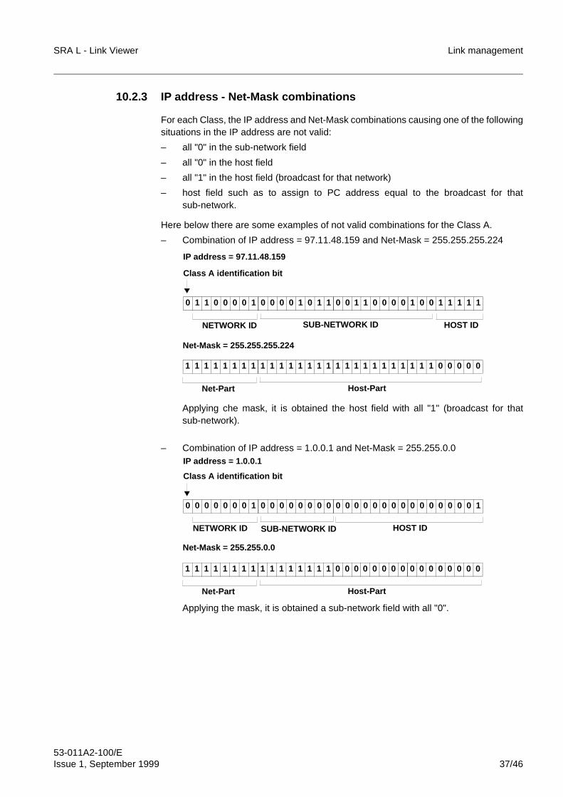
10.2.3 IP address - Net-Mask combinations
For each Class, the IP address and Net-Mask combinations causing one of the followingsituations in the IP address are not valid:
– all "0" in the sub-network field
– all "0" in the host field
– all "1" in the host field (broadcast for that network)
– host field such as to assign to PC address equal to the broadcast for thatsub-network.
Here below there are some examples of not valid combinations for the Class A.
– Combination of IP address = 97.11.48.159 and Net-Mask = 255.255.255.224
Applying che mask, it is obtained the host field with all "1" (broadcast for thatsub-network).
– Combination of IP address = 1.0.0.1 and Net-Mask = 255.255.0.0
Applying the mask, it is obtained a sub-network field with all "0".
0 1 1 0 0 0 0 1 0 0 0 0 1 0 1 1 0 0 1 1 0 0 0 0 1 0 0 1 1 1 1 1
Class A identification bit
NETWORK ID SUB-NETWORK ID
IP address = 97.11.48.159
HOST ID
1 1 1 1 1 1 1 1 1 1 1 1 1 1 1 1 1 1 1 1 1 1 1 1 1 1 1 0 0 0 0 0
Net-Part
Net-Mask = 255.255.255.224
Host-Part
0 0 0 0 0 0 0 1 0 0 0 0 0 0 0 0 0 0 0 0 0 0 0 0 0 0 0 0 0 0 0 1
Class A identification bit
NETWORK ID SUB-NETWORK ID
IP address = 1.0.0.1
HOST ID
1 1 1 1 1 1 1 1 1 1 1 1 1 1 1 1 0 0 0 0 0 0 0 0 0 0 0 0 0 0 0 0
Net-Part
Net-Mask = 255.255.0.0
Host-Part
Link management SRA L - Link Viewer
53-011A2-100/E38/46 Issue 1, September 1999
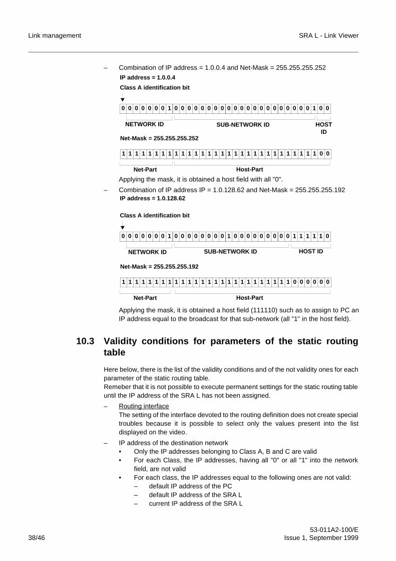
– Combination of IP address = 1.0.0.4 and Net-Mask = 255.255.255.252
Applying the mask, it is obtained a host field with all "0".
– Combination of IP address IP = 1.0.128.62 and Net-Mask = 255.255.255.192
Applying the mask, it is obtained a host field (111110) such as to assign to PC anIP address equal to the broadcast for that sub-network (all "1" in the host field).
10.3 Validity conditions for parameters of the static routingtable
Here below, there is the list of the validity conditions and of the not validity ones for eachparameter of the static routing table.Remeber that it is not possible to execute permanent settings for the static routing tableuntil the IP address of the SRA L has not been assigned.
– Routing interfaceThe setting of the interface devoted to the routing definition does not create specialtroubles because it is possible to select only the values present into the listdisplayed on the video.
– IP address of the destination network• Only the IP addresses belonging to Class A, B and C are valid• For each Class, the IP addresses, having all "0" or all "1" into the network
field, are not valid• For each class, the IP addresses equal to the following ones are not valid:
– default IP address of the PC– default IP address of the SRA L– current IP address of the SRA L
0 0 0 0 0 0 0 1 0 0 0 0 0 0 0 0 0 0 0 0 0 0 0 0 0 0 0 0 0 1 0 0
Class A identification bit
NETWORK ID SUB-NETWORK ID
IP address = 1.0.0.4
HOSTID
1 1 1 1 1 1 1 1 1 1 1 1 1 1 1 1 1 1 1 1 1 1 1 1 1 1 1 1 1 1 0 0
Net-Part
Net-Mask = 255.255.255.252
Host-Part
0 0 0 0 0 0 0 1 0 0 0 0 0 0 0 0 1 0 0 0 0 0 0 0 0 0 1 1 1 1 1 0
Class A identification bit
NETWORK ID SUB-NETWORK ID
IP address = 1.0.128.62
HOST ID
1 1 1 1 1 1 1 1 1 1 1 1 1 1 1 1 1 1 1 1 1 1 1 1 1 1 0 0 0 0 0 0
Net-Part
Net-Mask = 255.255.255.192
Host-Part
SRA L - Link Viewer Link management
53-011A2-100/EIssue 1, September 1999 39/46
– IP address of the local sub-network– IP address for broadcast of the local sub-network.
– IP address of the gateway • The same validity conditions of the SRA L IP addresses are valid (refer to par.
10.2)• For each Class, the current IP address of the SRA L is not valid.
10.4 Validity conditions for the F interface parameters (PC)
The setting of the F interface parameters (link and baud-rate protocol) does not createspecial troubles because it is possible to select only the values present into the listdisplayed on the video.Check that the used hardware (PC and, in case of remote connection, modem) supportsthe executed settings.
10.5 Reset of the TCP/IP parameters
It is possible to execute the reset of the TCP/IP parameters assigning the IP address =0.0.0.0.This operation causes the deleting as of the IP address and of the relevant Net-Mask asthe settings into the static routing table.On the contrary, the protocol and the baud-rate relevant to the F interface remains thecurrent ones.Then the reset of the TCP/IP parameters is automatically executed when the followingconditions are present:
– when it is changed the IP address of the SRA L
– when during the start-up phase, the system detects some IP address andNet-Mask values or combinations not valid.
Link management SRA L - Link Viewer
53-011A2-100/E40/46 Issue 1, September 1999
11 EXAMPLES OF SRA L LINK
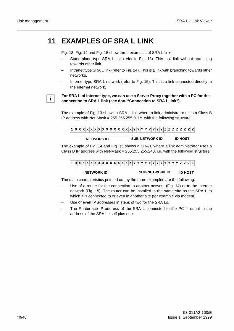
Fig. 13, Fig. 14 and Fig. 15 show three examples of SRA L link:
– Stand-alone type SRA L link (refer to Fig. 13). This is a link without branchingtowards other link.
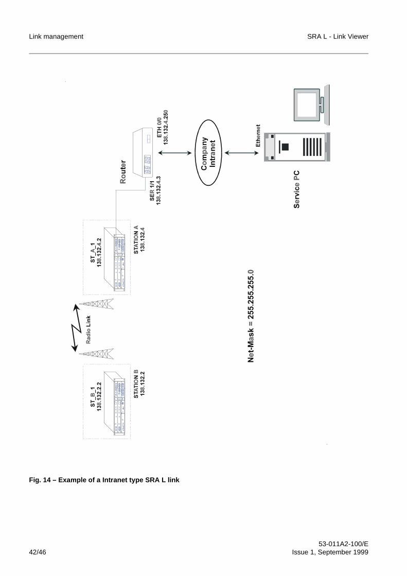
– Intranet type SRA L link (refer to Fig. 14). This is a link with branching towards othernetworks.
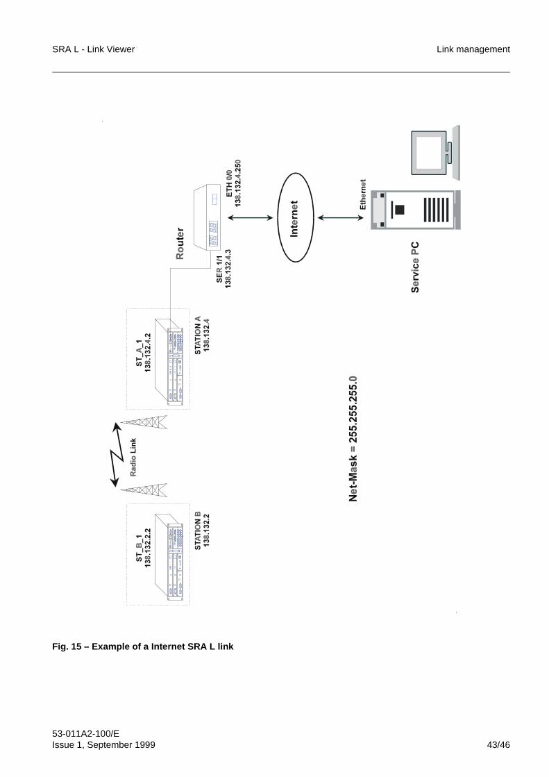
– Internet type SRA L network (refer to Fig. 15). This is a link connected directly tothe Internet network.
The example of Fig. 13 shows a SRA L link where a link administrator uses a Class BIP address with Net-Mask = 255.255.255.0, i.e. with the following structure:
The example of Fig. 14 and Fig. 15 shows a SRA L where a link administrator uses aClass B IP address with Net-Mask = 255.255.255.240, i.e. with the following structure:
The main characteristics pointed out by the three examples are the following:
– Use of a router for the connection to another network (Fig. 14) or to the Internetnetwork (Fig. 15). The router can be installed in the same site as the SRA L towhich it is connected to or even in another site (for example via modem).
– Use of even IP addresses in steps of two for the SRA Ls.
– The F interface IP address of the SRA L connected to the PC is equal to theaddress of the SRA L itself plus one.
For SRA L of Internet type, we can use a Server Proxy together with a PC for theconnection to SRA L link (see doc. “Connection to SRA L link”).i
1 0 X X X X X X X X X X X X X X Y Y Y Y Y Y Y Y Z Z Z Z Z Z Z Z
NETWORK ID SUB-NETWORK ID ID HOST
1 0 X X X X X X X X X X X X X X Y Y Y Y Y Y Y Y Y Y Y Y Z Z Z Z
NETWORK ID SUB-NETWORK ID ID HOST
SRA L - Link Viewer Link management
53-011A2-100/EIssue 1, September 1999 41/46
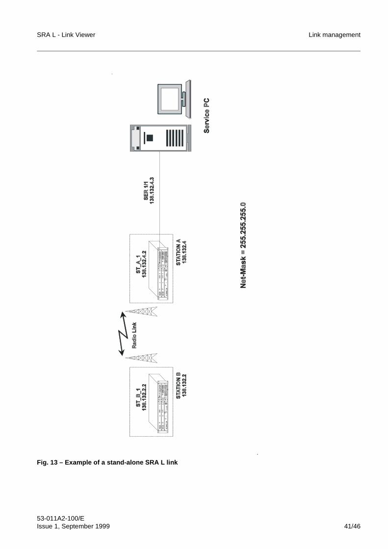
Fig. 13 – Example of a stand-alone SRA L link
Link management SRA L - Link Viewer
53-011A2-100/E42/46 Issue 1, September 1999
Fig. 14 – Example of a Intranet type SRA L link
SRA L - Link Viewer Link management
53-011A2-100/EIssue 1, September 1999 43/46
Fig. 15 – Example of a Internet SRA L link
Link management SRA L - Link Viewer
53-011A2-100/E44/46 Issue 1, September 1999
12 MAIN PROBLEMS OCCURRING IN THESRA L LINK MANAGEMENT
12.1 Common problems in Windows 3.1/3.11 and Windows 95/NT
• F interface: no possibilit y to ne gotiate the TCP Protocol with the SRA L.Verify the correct configuration of the service PC (remote access or Ethernetnetwork board for Windows 95/NT, SuperTCP setup for Windows 3.1/3.11).In case the serial interface is used, check the interconnection cable PC - IDU.Check whether the SRA L is on and has completed the reset operation.
• F interface: durin g loadin g of the localsral ma p, the icon remains grey.Close the Link Viewer and check whether the TCP protocol is correctly operating.
• F interface: the o perator cannot remember the IP address of the SRA L.Estblish a connection with the SRA L using the default address (loca map) andcheck the IP address. As an alternative, execute Ping from DOS to check whetherthe protocol is operating. The SRA L will reply signalling its specific IP address. Inthis case, it will be the default address.
• F interface: the su pervision is lost when chan ging the SRA L IP address.Every time an IP address or the system type of the SRA L is changed, a newstart-up of the working session is required (application program and protocol).
• V bus: after havin g executed the connection, it is not possible to "see" theSRA L installed downstream of the bus.Check whether all the hosts on the V bus belong to the same sub-network. Checkwhether the V bus is has the correct terminations.
• Address plannin g: usin g Class A addresses, it is not possible to monitor allthe SRA Ls.Check whether for the Class A addresses a Net-Mask is used which is at leastequal to 16 (255.255.0.0).
12.2 Common problems in Windows 95/NT
• "hosts" file: after havin g updated the "hosts" file, the icons on the ma premain grey.The "hosts" file is read by Windows 95/NT only during the opening. To activateevery possible change on such a file, it is necessary to start Windows and the LinkViewer application again.
SRA L - Link Viewer Link management
53-011A2-100/EIssue 1, September 1999 45/46
13 BIBLIOGRAPHY
– Internetworking with TCP/IPDouglas - E. ComerGruppo Editoriale JacksonISBN 88-256-0346-0
– TCP/IP HandbookUyless BlackMcGraw-HillISBN 88-386-0346-4
– TCP/IP vs. OSIPlanning for a Open Systems StandardComputer Technology Research Corp.ISBN 1-56607-012-0
– Microsoft Windows 95Resource KitMicrosoft Professional EditionISBN 1-55615-678-2
– Microsoft Windows 98Resource KitMicrosoft Professional EditionISBN 1-57231-644-6
– Microsfot Windows NT Server 4.0Resource KitMicrosoft Professinal EditionISBN 1-57231-344-7
– Microsoft Windows NT Workstation 4.0Resource KitMicrosoft Professional EditionISBN 1-57231-343-9

Link management SRA L - Link Viewer
53-011A2-100/E46/46 Issue 1, September 1999
FINE
BLANK PAGE
65$�/���/LQN�9LHZHU65$�/�PDQDJHPHQW�V\VWHP�
,QVWDOODWLRQ�RI�OLQN�VRIWZDUH
������$������(,VVXH����6HSWHPEHU�����

Installation of link software SRA L - Link Viewer
53-011A2-200/E2/128 Issue 1, September 1999
BLANK PAGE
SRA L - Link Viewer Installation of link software
53-011A2-200/EIssue 1, September 1999 3/128
Contents
1 OVERVIEW . . . . . . . . . . . . . . . . . . . . . . . . . . . . . . . . . . . . . . . . . . . . . . . . . 8
2 SYSTEM REQUIREMENTS . . . . . . . . . . . . . . . . . . . . . . . . . . . . . . . . . . . . 92.1 System requirements under Windows 3.1/3.11 . . . . . . . . . . . . . . . . . . . . . . 92.2 System requirements under Windows 95/NT 4.0 . . . . . . . . . . . . . . . . . . . . 10
3 CONNECTION BETWEEN THE SERVICE PC AND THE SRA L LINK . . 11
4 SOFTWARE INSTALLATION IN WINDOWS 3.1/3.11 . . . . . . . . . . . . . . . 124.1 Installation of the SuperTCP program. . . . . . . . . . . . . . . . . . . . . . . . . . . . . 124.2 Configuration of the serial service PC interface . . . . . . . . . . . . . . . . . . . . . 294.3 Installation of Link Viewer software. . . . . . . . . . . . . . . . . . . . . . . . . . . . . . . 364.4 Installation of SRA L software plugs-in . . . . . . . . . . . . . . . . . . . . . . . . . . . . 42
5 SOFTWARE INSTALLATION IN WINDOWS 95/NT 4.0 . . . . . . . . . . . . . . 435.1 Configuration of the connection with the SRA L link
. . . . . . . . . . . . . . . by means of a serial RS-232C interface in Windows 95435.1.1 Check whether software requirements are met . . . . . . . . . . . . . . . . . . . . . 445.1.2 Installation of the direct connection via cable . . . . . . . . . . . . . . . . . . . . . . . 465.1.3 Creation and configuration of the dial-up connection with SRA L. . . . . . . . 535.1.4 Configuration of the TCP/IP protocol . . . . . . . . . . . . . . . . . . . . . . . . . . . . . 645.2 Configuration of the connection to the SRA L link by
. . . . . . . . . . . . . . . . . . means of RS-232C serial interface in Windows NT695.2.1 Installation and configuration of the direct connection via cable. . . . . . . . . 705.2.2 Configuration of the remote access service (RAS) . . . . . . . . . . . . . . . . . . . 785.2.3 Creation and configuration of the dial-up connection towards SRA L. . . . . 835.3 Configuration of the connection to the SRA L link by
. . . . . . . . . . . . . . . . . . . . . means of Ethernet interface in Windows 95/NT975.3.1 Configuration of the TCP/IP protocol in Windows 95 . . . . . . . . . . . . . . . . . 975.3.2 Configuration of the TCP/IP protocol in Windows NT . . . . . . . . . . . . . . . . 1055.4 Installation of the link software . . . . . . . . . . . . . . . . . . . . . . . . . . . . . . . . . 1105.4.1 Installation of Link Viewer software. . . . . . . . . . . . . . . . . . . . . . . . . . . . . . 1105.4.2 . . . . . . . . . . . . . . . . . . . . . . . . . . . . Installation of the program SuperTCP1165.5 Installation of SRA L software plugs-in . . . . . . . . . . . . . . . . . . . . . . . . . . . 122
6 CREATION OF THE HOST TABLE . . . . . . . . . . . . . . . . . . . . . . . . . . . . . 1226.1 Creation of the host table under Windows 3.1/3.11 . . . . . . . . . . . . . . . . . 1236.2 Creation of the host table under Windows 95/NT . . . . . . . . . . . . . . . . . . . 127
Installation of link software SRA L - Link Viewer
53-011A2-200/E4/128 Issue 1, September 1999
IllustrationsFig. 1 Installation of the SuperTCP program (1/12) . . . . . . . . . . . . . . . . . . . . . . . . 14
Fig. 2 Installation of the SuperTCP program (2/12) . . . . . . . . . . . . . . . . . . . . . . . . 15
Fig. 3 Installation of the SuperTCP program (3/12) . . . . . . . . . . . . . . . . . . . . . . . . 15
Fig. 4 Installation of the SuperTCP program (4/12) . . . . . . . . . . . . . . . . . . . . . . . . 16
Fig. 5 Installation of the SuperTCP program (5/12) . . . . . . . . . . . . . . . . . . . . . . . . 16
Fig. 6 Installation of the SuperTCP program (6/12) . . . . . . . . . . . . . . . . . . . . . . . . 17
Fig. 7 Installation of the SuperTCP program (7/12) . . . . . . . . . . . . . . . . . . . . . . . . 17
Fig. 8 Installation of the SuperTCP program (8/12) . . . . . . . . . . . . . . . . . . . . . . . . 18
Fig. 9 Installation of the SuperTCP program (9/12) . . . . . . . . . . . . . . . . . . . . . . . . 18
Fig. 10 Installation of the SuperTCP program (10/12) . . . . . . . . . . . . . . . . . . . . . . . 19
Fig. 11 Installation of the SuperTCP program (11/12) . . . . . . . . . . . . . . . . . . . . . . . 19
Fig. 12 Installation of the SuperTCP program (12/12) . . . . . . . . . . . . . . . . . . . . . . . 20
Fig. 13 SuperTCP program configuration (1/16) . . . . . . . . . . . . . . . . . . . . . . . . . . . 20
Fig. 14 SuperTCP program configuration (2/16) . . . . . . . . . . . . . . . . . . . . . . . . . . . 21
Fig. 15 SuperTCP program configuration (3/16) . . . . . . . . . . . . . . . . . . . . . . . . . . . 21
Fig. 16 SuperTCP program configuration (4/16) . . . . . . . . . . . . . . . . . . . . . . . . . . . 22
Fig. 17 SuperTCP program configuration (5/16) . . . . . . . . . . . . . . . . . . . . . . . . . . . 22
Fig. 18 SuperTCP program configuration (6/16) . . . . . . . . . . . . . . . . . . . . . . . . . . . 23
Fig. 19 SuperTCP program configuration (7/16) . . . . . . . . . . . . . . . . . . . . . . . . . . . 23
Fig. 20 SuperTCP program configuration (8/16) . . . . . . . . . . . . . . . . . . . . . . . . . . . 24
Fig. 21 SuperTCP program configuration (9/16) . . . . . . . . . . . . . . . . . . . . . . . . . . . 24
Fig. 22 SuperTCP program configuration (10/16) . . . . . . . . . . . . . . . . . . . . . . . . . . 25
Fig. 23 SuperTCP program configuration (11/16) . . . . . . . . . . . . . . . . . . . . . . . . . . 25
Fig. 24 SuperTCP program configuration (12/16) . . . . . . . . . . . . . . . . . . . . . . . . . . 26
Fig. 25 SuperTCP program configuration (13/16) . . . . . . . . . . . . . . . . . . . . . . . . . . 26
Fig. 26 SuperTCP program configuration (14/16) . . . . . . . . . . . . . . . . . . . . . . . . . . 27
Fig. 27 SuperTCP program configuration (15/16) . . . . . . . . . . . . . . . . . . . . . . . . . . 27
Fig. 28 SuperTCP program configuration (16/16) . . . . . . . . . . . . . . . . . . . . . . . . . . 28
Fig. 29 . Example of “autoexec.bat” file after installation of the SuperTCP program28
Fig. 30 Serial interface configuration (1/11) . . . . . . . . . . . . . . . . . . . . . . . . . . . . . . . 30
Fig. 31 Serial interface configuration (2/11) . . . . . . . . . . . . . . . . . . . . . . . . . . . . . . . 31
Fig. 32 Serial interface configuration (3/11) . . . . . . . . . . . . . . . . . . . . . . . . . . . . . . . 31
Fig. 33 Serial interface configuration (4/11) . . . . . . . . . . . . . . . . . . . . . . . . . . . . . . . 32
Fig. 34 Serial interface configuration (5/11) . . . . . . . . . . . . . . . . . . . . . . . . . . . . . . . 32
Fig. 35 Serial interface configuration (6/11) . . . . . . . . . . . . . . . . . . . . . . . . . . . . . . . 33
Fig. 36 Serial interface configuration (7/11) . . . . . . . . . . . . . . . . . . . . . . . . . . . . . . . 33
Fig. 37 Serial interface configuration (8/11) . . . . . . . . . . . . . . . . . . . . . . . . . . . . . . . 34
Fig. 38 Serial interface configuration (9/11) . . . . . . . . . . . . . . . . . . . . . . . . . . . . . . . 34
Fig. 39 Serial interface configuration (10/11) . . . . . . . . . . . . . . . . . . . . . . . . . . . . . . 35
Fig. 40 Serial interface configuration (11/11) . . . . . . . . . . . . . . . . . . . . . . . . . . . . . . 35
Fig. 41 Installation of Link Viewer software (1/9) . . . . . . . . . . . . . . . . . . . . . . . . . . . 37
Fig. 42 Installation of Link Viewer software (2/9) . . . . . . . . . . . . . . . . . . . . . . . . . . . 37
Fig. 43 Installation of Link Viewer software (3/9) . . . . . . . . . . . . . . . . . . . . . . . . . . . 38
SRA L - Link Viewer Installation of link software
53-011A2-200/EIssue 1, September 1999 5/128
Fig. 44 Installation of Link Viewer software (4/9) . . . . . . . . . . . . . . . . . . . . . . . . . . 38
Fig. 45 Installation of Link Viewer software (5/9) . . . . . . . . . . . . . . . . . . . . . . . . . . 39
Fig. 46 Installation of Link Viewer software (6/9) . . . . . . . . . . . . . . . . . . . . . . . . . . 39
Fig. 47 Installation of Link Viewer software (7/9) . . . . . . . . . . . . . . . . . . . . . . . . . . 40
Fig. 48 Installation of Link Viewer software (8/9) . . . . . . . . . . . . . . . . . . . . . . . . . . 40
Fig. 49 Installation of Link Viewer software (9/9) . . . . . . . . . . . . . . . . . . . . . . . . . . 41
Fig. 50 Check whether software requirements are met (1/4) . . . . . . . . . . . . . . . . . 44
Fig. 51 Check whether software requirements are met (2/4) . . . . . . . . . . . . . . . . . 45
Fig. 52 Check whether software requirements are met (3/4) . . . . . . . . . . . . . . . . . 45
Fig. 53 Check whether software requirements are met (4/4) . . . . . . . . . . . . . . . . . 46
Fig. 54 Installation of the direct connection (1/11) . . . . . . . . . . . . . . . . . . . . . . . . . 47
Fig. 55 Installation of the direct connection (2/11) . . . . . . . . . . . . . . . . . . . . . . . . . 48
Fig. 56 Installation of the direct connection (3/11) . . . . . . . . . . . . . . . . . . . . . . . . . 48
Fig. 57 Installation of the direct connection (4/11) . . . . . . . . . . . . . . . . . . . . . . . . . 49
Fig. 58 Installation of the direct connection (5/11) . . . . . . . . . . . . . . . . . . . . . . . . . 49
Fig. 59 Installation of the direct connection (6/11) . . . . . . . . . . . . . . . . . . . . . . . . . 50
Fig. 60 Installation of the direct connection (7/11) . . . . . . . . . . . . . . . . . . . . . . . . . 50
Fig. 61 Installation of the direct connection (8/11) . . . . . . . . . . . . . . . . . . . . . . . . . 51
Fig. 62 Installation of the direct connection (9/11) . . . . . . . . . . . . . . . . . . . . . . . . . 51
Fig. 63 Installation of the direct connection (10/11) . . . . . . . . . . . . . . . . . . . . . . . . 52
Fig. 64 Installation of the direct connection (11/11) . . . . . . . . . . . . . . . . . . . . . . . . 52
Fig. 65 Creation of the dial-up connection with SRA L (1/10) . . . . . . . . . . . . . . . . . 54
Fig. 66 Creation of the dial-up connection with SRA L (2/10) . . . . . . . . . . . . . . . . . 55
Fig. 67 Creation of the dial-up connection with SRA L (3/10) . . . . . . . . . . . . . . . . . 55
Fig. 68 Creation of the dial-up connection with SRA L (4/10) . . . . . . . . . . . . . . . . . 56
Fig. 69 Creation of the dial-up connection with SRA L (5/10) . . . . . . . . . . . . . . . . . 56
Fig. 70 Creation of the dial-up connection with SRA L (6/10) . . . . . . . . . . . . . . . . . 57
Fig. 71 Creation of the dial-up connection with SRA L (7/10) . . . . . . . . . . . . . . . . . 57
Fig. 72 Creation of the dial-up connection with SRA L (8/10) . . . . . . . . . . . . . . . . . 58
Fig. 73 Creation of the dial-up connection with SRA L (9/10) . . . . . . . . . . . . . . . . . 58
Fig. 74 Creation of the dial-up connection with SRA L (10/10) . . . . . . . . . . . . . . . . 59
Fig. 75 Creation of the dial-up connection with SRA L (1/10) . . . . . . . . . . . . . . . . . 59
Fig. 76 Creation of the dial-up connection with SRA L (2/10) . . . . . . . . . . . . . . . . . 60
Fig. 77 Creation of the dial-up connection with SRA L (3/10) . . . . . . . . . . . . . . . . . 60
Fig. 78 Creation of the dial-up connection with SRA L (4/10) . . . . . . . . . . . . . . . . . 61
Fig. 79 Creation of the dial-up connection with SRA L (5/10) . . . . . . . . . . . . . . . . . 61
Fig. 80 Creation of the dial-up connection with SRA L (6/10) . . . . . . . . . . . . . . . . . 62
Fig. 81 Creation of the dial-up connection with SRA L (7/10) . . . . . . . . . . . . . . . . . 62
Fig. 82 Creation of the dial-up connection with SRA L (8/10) . . . . . . . . . . . . . . . . . 63
Fig. 83 Creation of the dial-up connection with SRA L (9/10) . . . . . . . . . . . . . . . . . 63
Fig. 84 Creation of the dial-up connection with SRA L (10/10) . . . . . . . . . . . . . . . . 64
Fig. 85 TCP/IP protocol configuration (1/9). . . . . . . . . . . . . . . . . . . . . . . . . . . . . . . 65
Fig. 86 TCP/IP protocol configuration (2/9). . . . . . . . . . . . . . . . . . . . . . . . . . . . . . . 65
Fig. 87 TCP/IP protocol configuration (3/9). . . . . . . . . . . . . . . . . . . . . . . . . . . . . . . 66
Installation of link software SRA L - Link Viewer
53-011A2-200/E6/128 Issue 1, September 1999
Fig. 88 TCP/IP protocol configuration (4/9) . . . . . . . . . . . . . . . . . . . . . . . . . . . . . . . 66
Fig. 89 TCP/IP protocol configuration (5/9) . . . . . . . . . . . . . . . . . . . . . . . . . . . . . . . 67
Fig. 90 TCP/IP protocol configuration (6/9) . . . . . . . . . . . . . . . . . . . . . . . . . . . . . . . 67
Fig. 91 TCP/IP protocol configuration (7/9) . . . . . . . . . . . . . . . . . . . . . . . . . . . . . . . 68
Fig. 92 TCP/IP protocol configuration (8/9) . . . . . . . . . . . . . . . . . . . . . . . . . . . . . . . 68
Fig. 93 TCP/IP protocol configuration (9/9) . . . . . . . . . . . . . . . . . . . . . . . . . . . . . . . 69
Fig. 94 Installation and configuration of the direct connection (1/14). . . . . . . . . . . . 71
Fig. 95 Installation and configuration of the direct connection (2/14). . . . . . . . . . . . 71
Fig. 96 Installation and configuration of the direct connection (3/14). . . . . . . . . . . . 72
Fig. 97 Installation and configuration of the direct connection (4/14). . . . . . . . . . . . 72
Fig. 98 Installation and configuration of the direct connection (5/14). . . . . . . . . . . . 73
Fig. 99 Installation and configuration of the direct connection (6/14). . . . . . . . . . . . 73
Fig. 100 Installation and configuration of the direct connection (7/14). . . . . . . . . . . . 74
Fig. 101 Installation and configuration of the direct connection (8/14). . . . . . . . . . . . 74
Fig. 102 Installation and configuration of the direct connection (9/14). . . . . . . . . . . . 75
Fig. 103 Installation and configuration of the direct connection (10/14). . . . . . . . . . . 75
Fig. 104 Installation and configuration of the direct connection (11/14). . . . . . . . . . . 76
Fig. 105 Installation and configuration of the direct connection (12/14). . . . . . . . . . . 76
Fig. 106 Installation and configuration of the direct connection (13/14). . . . . . . . . . . 77
Fig. 107 Installation and configuration of the direct connection (14/14). . . . . . . . . . . 77
Fig. 108 Configuration of the RAS service (1/9). . . . . . . . . . . . . . . . . . . . . . . . . . . . . 79
Fig. 109 Configuration of the RAS service (2/9). . . . . . . . . . . . . . . . . . . . . . . . . . . . . 79
Fig. 110 Configuration of the RAS service (3/9). . . . . . . . . . . . . . . . . . . . . . . . . . . . . 80
Fig. 111 Configuration of the RAS service (4/9). . . . . . . . . . . . . . . . . . . . . . . . . . . . . 80
Fig. 112 Configuration of the RAS service (5/9). . . . . . . . . . . . . . . . . . . . . . . . . . . . . 81
Fig. 113 Configuration of the RAS service (6/9). . . . . . . . . . . . . . . . . . . . . . . . . . . . . 81
Fig. 114 Configuration of the RAS service (7/9). . . . . . . . . . . . . . . . . . . . . . . . . . . . . 82
Fig. 115 Configuration of the RAS service (8/9). . . . . . . . . . . . . . . . . . . . . . . . . . . . . 82
Fig. 116 Configuration of the RAS service (9/9). . . . . . . . . . . . . . . . . . . . . . . . . . . . . 83
Fig. 141 Configuration of the TCP/IP protocol (1/12) . . . . . . . . . . . . . . . . . . . . . . . . . 98
Fig. 142 Configuration of the TCP/IP protocol (2/12) . . . . . . . . . . . . . . . . . . . . . . . . . 99
Fig. 143 Configuration of the TCP/IP protocol (3/12) . . . . . . . . . . . . . . . . . . . . . . . . . 99
Fig. 144 Configuration of the TCP/IP protocol (4/12) . . . . . . . . . . . . . . . . . . . . . . . . 100
Fig. 145 Configuration of the TCP/IP protocol (5/12) . . . . . . . . . . . . . . . . . . . . . . . . 100
Fig. 146 Configuration of the TCP/IP protocol (6/12) . . . . . . . . . . . . . . . . . . . . . . . . 101
Fig. 147 Configuration of the TCP/IP protocol (7/12) . . . . . . . . . . . . . . . . . . . . . . . . 101
Fig. 148 Configuration of the TCP/IP protocol (8/12) . . . . . . . . . . . . . . . . . . . . . . . . 102
Fig. 149 Configuration of the TCP/IP protocol (9/12) . . . . . . . . . . . . . . . . . . . . . . . . 102
Fig. 150 Configuration of the TCP/IP protocol (10/12) . . . . . . . . . . . . . . . . . . . . . . . 103
Fig. 151 Configuration of the TCP/IP protocol (11/12) . . . . . . . . . . . . . . . . . . . . . . . 103
Fig. 152 Configuration of the TCP/IP protocol (12/12) . . . . . . . . . . . . . . . . . . . . . . . 104
Fig. 153 TCP/IP protocol configuration (1/9) . . . . . . . . . . . . . . . . . . . . . . . . . . . . . . 106
Fig. 154 TCP/IP protocol configuration (2/9) . . . . . . . . . . . . . . . . . . . . . . . . . . . . . . 106
Fig. 155 TCP/IP protocol configuration (3/9) . . . . . . . . . . . . . . . . . . . . . . . . . . . . . . 107
SRA L - Link Viewer Installation of link software
53-011A2-200/EIssue 1, September 1999 7/128
Fig. 156 TCP/IP protocol configuration (4/9). . . . . . . . . . . . . . . . . . . . . . . . . . . . . . 107
Fig. 157 TCP/IP protocol configuration (5/9). . . . . . . . . . . . . . . . . . . . . . . . . . . . . . 108
Fig. 158 TCP/IP protocol configuration (6/9). . . . . . . . . . . . . . . . . . . . . . . . . . . . . . 108
Fig. 159 TCP/IP protocol configuration (7/9). . . . . . . . . . . . . . . . . . . . . . . . . . . . . . 109
Fig. 160 TCP/IP protocol configuration (8/9). . . . . . . . . . . . . . . . . . . . . . . . . . . . . . 109
Fig. 161 TCP/IP protocol configuration (9/9). . . . . . . . . . . . . . . . . . . . . . . . . . . . . . 110
Fig. 162 Installation of Link Viewer software (1/9) . . . . . . . . . . . . . . . . . . . . . . . . . 112
Fig. 163 Installation of Link Viewer software (2/9) . . . . . . . . . . . . . . . . . . . . . . . . . 112
Fig. 164 Installation of Link Viewer software (3/9) . . . . . . . . . . . . . . . . . . . . . . . . . 113
Fig. 165 Installation of Link Viewer software (4/9) . . . . . . . . . . . . . . . . . . . . . . . . . 113
Fig. 166 Installation of Link Viewer software (5/9) . . . . . . . . . . . . . . . . . . . . . . . . . 114
Fig. 167 Installation of Link Viewer software (6/9) . . . . . . . . . . . . . . . . . . . . . . . . . 114
Fig. 168 Installation of Link Viewer software (7/9) . . . . . . . . . . . . . . . . . . . . . . . . . 115
Fig. 169 Installation of Link Viewer software (8/9) . . . . . . . . . . . . . . . . . . . . . . . . . 115
Fig. 170 Installation of Link Viewer software (9/9) . . . . . . . . . . . . . . . . . . . . . . . . . 116
Fig. 171 Installation of the SuperTCP program (1/9) . . . . . . . . . . . . . . . . . . . . . . . 117
Fig. 172 Installation of the SuperTCP program (2/9) . . . . . . . . . . . . . . . . . . . . . . . 118
Fig. 173 Installation of the SuperTCP program (3/9) . . . . . . . . . . . . . . . . . . . . . . . 118
Fig. 174 Installation of the SuperTCP program (4/9) . . . . . . . . . . . . . . . . . . . . . . . 119
Fig. 175 Installation of the SuperTCP program (5/9) . . . . . . . . . . . . . . . . . . . . . . . 119
Fig. 176 Installation of the SuperTCP program (6/9) . . . . . . . . . . . . . . . . . . . . . . . 120
Fig. 177 Installation of the SuperTCP program (7/9) . . . . . . . . . . . . . . . . . . . . . . . 120
Fig. 178 Installation of the SuperTCP program (8/9) . . . . . . . . . . . . . . . . . . . . . . . 121
Fig. 179 Installation of the SuperTCP program (9/9) . . . . . . . . . . . . . . . . . . . . . . . 121
Fig. 180 Creation of the host table (1/6) . . . . . . . . . . . . . . . . . . . . . . . . . . . . . . . . . 124
Fig. 181 Creation of the host table (2/6) . . . . . . . . . . . . . . . . . . . . . . . . . . . . . . . . . 124
Fig. 182 Creation of the host table (3/6) . . . . . . . . . . . . . . . . . . . . . . . . . . . . . . . . . 125
Fig. 183 Creation of the host table (4/6) . . . . . . . . . . . . . . . . . . . . . . . . . . . . . . . . . 125
Fig. 184 Creation of the host table (5/6) . . . . . . . . . . . . . . . . . . . . . . . . . . . . . . . . . 126
Fig. 185 Creation of the host table (6/6) . . . . . . . . . . . . . . . . . . . . . . . . . . . . . . . . . 126
Fig. 186 Example for the file “hosts” . . . . . . . . . . . . . . . . . . . . . . . . . . . . . . . . . . . . 127
SRA L - Link Viewer Installation of link software
53-011A2-200/EIssue 1, September 1999 8/128
1 OVERVIEWThe link software is provided on CD-ROM, with the serial number and the passwordannexed.The installation CD-ROM contents:
– the software for the SRA L link management
– the SuperTCP program
– SRA L software plugs-in:• 8x2 Mbit/s software plug-in SRA L • 16x2 Mbit/s software plug-in SRA L • Full ODU software plug-in SRA L
– the drivers for the connection via cable for Windows 95/NT.
In case of installation on PC not equipped with CD-ROM drive, it is possible to obtainthe installation floppy-disks of the programs and the plug-in from the relevant copypresent on CD-ROM.
The SRA L link management program is composed by two application programs forWindows:
– Link Viewer, which constitutes the true control and configuration program of theSRA L link; for each type of SRA L, there is a specific plug-in software, whichmakes the Link Viewer program able to manage the equipment
– Net Builder, for the creation of link maps.
For connection to the SRA L link, the service PC must be equipped with the TCP/IPprotocol.
The set of SRA L plugs_in can be requested/provided also on the specificCD-ROM.
To obtain the version of a program on floppy-disk, it is necessary to assure theuse of formatted floppy-disk, completely empty, without label and free fromdamages clusters and viruses.7KH�LPDJH�RQ�&'�RI�WKH�IORSS\�GLVN����RI�WKH�6XSHU7&3�SURJUDP�LV�ELJJHU�WKDQWKH�PD[LPXP�FDSDFLW\�RI�D�IORSS\�GLVN�7R�REWDLQ�WKH�IORSS\�GLVN����LW�LV�QHFHVVDU\�WR�H[HFXWH�WKH�IROORZLQJ�SURFHGXUH��• FRS\�DOO�WKH�ILOHV�IURP�WKH�³����?7FS�LQV?)ORSS\?7FSBGLVN���´�GLUHFWRU\��ZLWK
WKH�H[FHSWLRQ�RI�WKH�³7XWWRF�KOS´�ILOH��WR�WKH�IORSS\�GLVN���• FRS\�WKH�³7XWWRF�KOS´�ILOH�RQ�D�UHVHUYH�IORSS\�GLVN�'XULQJ�WKH�6XSHU7&3�SURJUDP�LQVWDOODWLRQ�IURP�IORSS\�GLVN�DW�WKH�UHTXHVW�RI�WKHIORSS\�GLVN�����LW�LV�QHFHVVDU\�WR�H[HFXWH�WKH�IROORZLQJ�SURFHGXUH�• LQVHUW�WKH�IORSS\�GLVN���• ZKHQ� WKH� HUURU� PHVVDJH� LV� GLVSOD\HG�� LQVHUW� WKH� UHVHUYH� IORSS\�GLVN
SURYLGHG�ZLWK�WKH�³7XWWRF�KOS´�ILOH• ZKHQ� WKH� QHZ� HUURU� PHVVDJH� LV� GLVSOD\HG� DW� WKH� HQG� RI� WKH� ORDGLQJ
SURFHGXUH�RI�WKH�³7XWWRF�KOS´�ILOH��LQVHUW�DJDLQ�WKH�IORSS\�GLVN����
i
i
Installation of link software SRA L - Link Viewer
53-011A2-200/E9/128 Issue 1, September 1999
The installation and configuration of the TCP/IP protocol differs depending on thesoftware:
– Windows 3.1/3.11The TCP/IP protocol provided by the SuperTCP program is used. The TCP/IPprotocol is available only with RS-232C serial interface (PPP or SLIP protocol).
– Windows 95/NT 4.0The TCP/IP protocol provided by the operating system itself is used, availableeither with serial RS-232C interface (PPP or SLIP protocol) or Ethernet interface.If the serial interface is used, it is necessary to install the direct connection mode.It is necessary to install the SuperTCP program also in Windows 95/NT, if theoperator wants to use the PC to execute the download of the unit software
(Controller unit, Q-Adapter unit) from remote, by means of FTP.
2 6<67(0�5(48,5(0(176
The following is a list of requirements for the service PC to manage a link SRA L,depending on the software.
2.1 6\VWHP�UHTXLUHPHQWV�XQGHU�:LQGRZV���������
– CPU Pentium 133 or higher
– 32 Mbyte RAM minimum
– 1 Gbyte Hard-disk minimum
– 1.4 Mbyte 3.5” floppy-disk drive
– VGA or higher video card
– CD-ROM drive
– Two RS-232C serial ports
– Mouse
– Pin-to-pin non-modem serial cable
Under Windows 95/NT, only the utilities of the SuperTCP program are installedbecause the software automatically detects the presence of the TCP/IP protocol.7KH�6XSHU7&3�SURJUDP�XWLOLWLHV�DOORZ�WR�ZRUN�XQGHU�:LQGRZV����17�LQ�JUDSKLFPRGH�
7KH�XVH�RI�D�3&�ZLWK�GRXEOH�ERRW�LV�QRW�UHFRPPHQGHG��,Q�D�/DSWRS�3&�RU�3&�ZLWK3RZHU�0DQDJHPHQW��WKLV�IXQFWLRQ�PXVW�QRW�EH�DFWLYDWHG�%HIRUH� UHPRYLQJ� WKH�VHULDO�FRQQHFWLRQ�FDEOH�� LW� LV�QHFHVVDU\� WR�H[LW�FRUUHFWO\IURP�DOO�UXQQLQJ�DSSOLFDWLRQ�SURJUDPV�LQ�RUGHU�WR�SUHYHQW�SRVVLEOH�FUDVKHV�
i
i
SRA L - Link Viewer Installation of link software
53-011A2-200/EIssue 1, September 1999 10/128
2.2 6\VWHP�UHTXLUHPHQWV�XQGHU�:LQGRZV����17����
– Hardware requirements:• CPU Pentium 133 or higher• 32 Mbyte RAM minimum• 1 Gbyte Hard-disk minimum• 1.4 Mbyte 3.5” floppy-disk drive• VGA or higher video card• CD-ROM drive• Two RS-232C serial ports• Mouse• Pin-to-pin non-modem serial cable (necessary only for connections via serial
interface)
– Software requirements in Windows 95:• Dial-up connection and direct connection over cable are supported
(necessary only for local connection via serial interface)• TCP/IP communication protocol installed for remote access (connection via
serial interface) or network card (connection via Ethernet interface)
– Software requirements in Windows NT 4.0:• TCP/IP communication protocol installed• Remote access service (RAS) installed (necessary only for local connection
via serial interface); in case of Windows NT Server, we advise you to install
the RRAS service instead of RAS service
)RU�VRIWZDUH�LQVWDOODWLRQ�XQGHU�:LQGRZV����17��WKH�:LQGRZV����17�LQVWDOODWLRQ&'�PXVW�EH�XVHG�)RU�FRQQHFWLRQV�YLD�(WKHUQHW� LQWHUIDFH��DOVR� WKH� IORSS\�GLVN�&'�520�ZLWK�WKHQHWZRUN�FDUG�GULYHUV�PXVW�EH�LQVWDOOHG�RQ�WKH�VHUYLFH�3&�
i
Installation of link software SRA L - Link Viewer
53-011A2-200/E11/128 Issue 1, September 1999
3 &211(&7,21�%(7:((1�7+(�6(59,&(�3&$1'�7+(�65$�/�/,1.
Several modes are available for the connection between the service PC and the SRA Llink:
– Direct connection through RS-232C serial interfaceThe service PC is connected directly by means of the proper cable to the localSRA L acting as the link access point.
– Remote connection through RS-232C serial interfaceA modem is used for the connection between the service PC and the SRA L link,which acts as link access point.
– Remote connection through Ethernet interface (not available for Windows 3.1/3.11). The router is connected in the network, via Ethernet interface, with theservice PC and it is directly connected, via modem, using the RS-232C serialinterface, with the SRA L, which operates as link access point.
– Remote connection on Ethernet interface via Server Proxy (not available forWindows 3.1/3.11)The PC with the Server Proxy currently in execution is connected, on the Ethernetinterface, to the Service PC and it is connected, directly or via modem, on RS-232Cserial interface, to the SRA L, which acts like link access point.
For more information, refer to doc. “Connection to SRA L link”.i
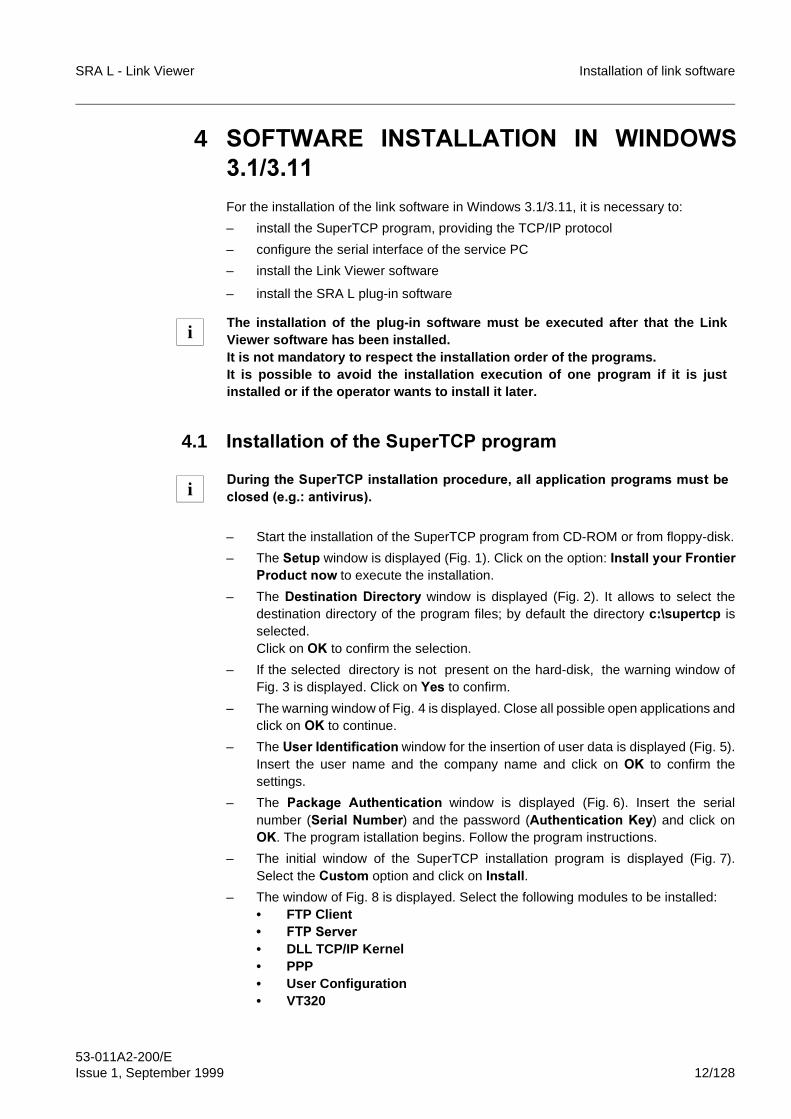
SRA L - Link Viewer Installation of link software
53-011A2-200/EIssue 1, September 1999 12/128
4 62)7:$5(� ,167$//$7,21� ,1� :,1'2:6��������
For the installation of the link software in Windows 3.1/3.11, it is necessary to:
– install the SuperTCP program, providing the TCP/IP protocol
– configure the serial interface of the service PC
– install the Link Viewer software
– install the SRA L plug-in software
4.1 ,QVWDOODWLRQ�RI�WKH�6XSHU7&3�SURJUDP
– Start the installation of the SuperTCP program from CD-ROM or from floppy-disk.
– The 6HWXS window is displayed (Fig. 1). Click on the option: ,QVWDOO�\RXU�)URQWLHU3URGXFW�QRZ to execute the installation.
– The 'HVWLQDWLRQ�'LUHFWRU\�window is displayed (Fig. 2). It allows to select thedestination directory of the program files; by default the directory c:\supertcp isselected.Click on 2. to confirm the selection.
– If the selected directory is not present on the hard-disk, the warning window ofFig. 3 is displayed. Click on <HV to confirm.
– The warning window of Fig. 4 is displayed. Close all possible open applications andclick on 2. to continue.
– The 8VHU�,GHQWLILFDWLRQ window for the insertion of user data is displayed (Fig. 5).Insert the user name and the company name and click on 2. to confirm thesettings.
– The 3DFNDJH� $XWKHQWLFDWLRQ window is displayed (Fig. 6). Insert the serialnumber (6HULDO�1XPEHU) and the password ($XWKHQWLFDWLRQ�.H\) and click on2.. The program istallation begins. Follow the program instructions.
– The initial window of the SuperTCP installation program is displayed (Fig. 7).Select the &XVWRP option and click on�,QVWDOO.
– The window of Fig. 8 is displayed. Select the following modules to be installed:• FTP Client� )73�6HUYHU• DLL TCP/IP Kernel• PPP• User Configuration• VT320
The installation of the plug-in software must be executed after that the LinkViewer software has been installed.It is not mandatory to respect the installation order of the programs.It is possible to avoid the installation execution of one program if it is justinstalled or if the operator wants to install it later.
'XULQJ�WKH�6XSHU7&3�LQVWDOODWLRQ�SURFHGXUH��DOO�DSSOLFDWLRQ�SURJUDPV�PXVW�EHFORVHG��H�J���DQWLYLUXV��
i
i
Installation of link software SRA L - Link Viewer
53-011A2-200/E13/128 Issue 1, September 1999
and click on�,QVWDOO.
– After completion of the installation phase, the window of Fig. 9 is displayed. Clickon 'RQH to confirm.
– Should the warning window of Fig. 10 be displayed, click on 2. to continue.
– At this point the group )URQWLHU�7HFKQRORJLHV is created in the window and thewarning window of Fig. 11 is displayed. Click on 2. to continue.
– The warning window, shown in Fig. 12 is displayed; click on 2. to continue.
– The initial window of the SuperTCP configuration program (Fig. 13) is displayed.Click on 1H[W.
– The window of Fig. Fig. 14 is displayed. Click on�1H[W.
– The window of Fig. 15 is displayed. Select the option ���2WKHU��333�����and click on1H[W.
– The window of Fig. 16 is displayed. Insert the following parameters:• SralProvider• 1234567and click on 1H[W.
– The 8VHUQDPH�3DVVZRUG window (Fig. 17) is displayed. Insert the user name andclick on 1H[W.
– The $XWKHQWLFDWLRQ�8VDJH window (Fig. 18) is displayed. Select the option 1RQHand click on 1H[W.
– The ,3�$GGUHVV�7\SH�6HOHFWLRQ window (Fig. 19) is displayed. Select the option'\QDPLF�$GGUHVVLQJ and click on 1H[W.
– The 0DFKLQH�DQG�'RPDLQ�1DPH window (Fig. 20) is displayed. Set the followingparameters:• IP Address Mask: 0.0.0.0and click on 1H[W.
– The 0DFKLQH�DQG�'RPDLQ�1DPH window (Fig. 21) is displayed. Set the followingparameters:• Machine Name: SralLpc• Domain Name: SralProviderand click on 1H[W.
– The window 'RPDLQ�1DPH�6HUYLFH (Fig. 22) is displayed. In this window the value������� is selected by default for the parameter 0DLQ�'RPDLQ�1DPH�6HUYHU. Click on 1H[W to continue.
– The window 'HIDXOW� *DWHZD\� (Fig. 23) is displayed. In this window the value������� is selected by default for the parameter ,3� $GGUHVV� RI� <RXU� 'HIDXOW*DWHZD\ .Click on 1H[W to continue.
– The window 0RGHP� 7\SH� 6HOHFWLRQ (Fig. 24) is displayed. Select the option���2WKHU��� and click on 1H[W.
– The window 0RGHP�&RQILJXUDWLRQ (Fig. 25) is displayed. Disactivate the options8VH�+DUGZDUH�)ORZ�&RQWURO and 8VHU�&DUULHU�'HWHFWLRQ and set the followingparameter for the serial port (usually COM1):• Baud Rate: 19200.Click on 1H[W to continue.
– The final window of the SuperTCP configuration program (Fig. 26) is displayed.Click on )LQLVK to end and exit.
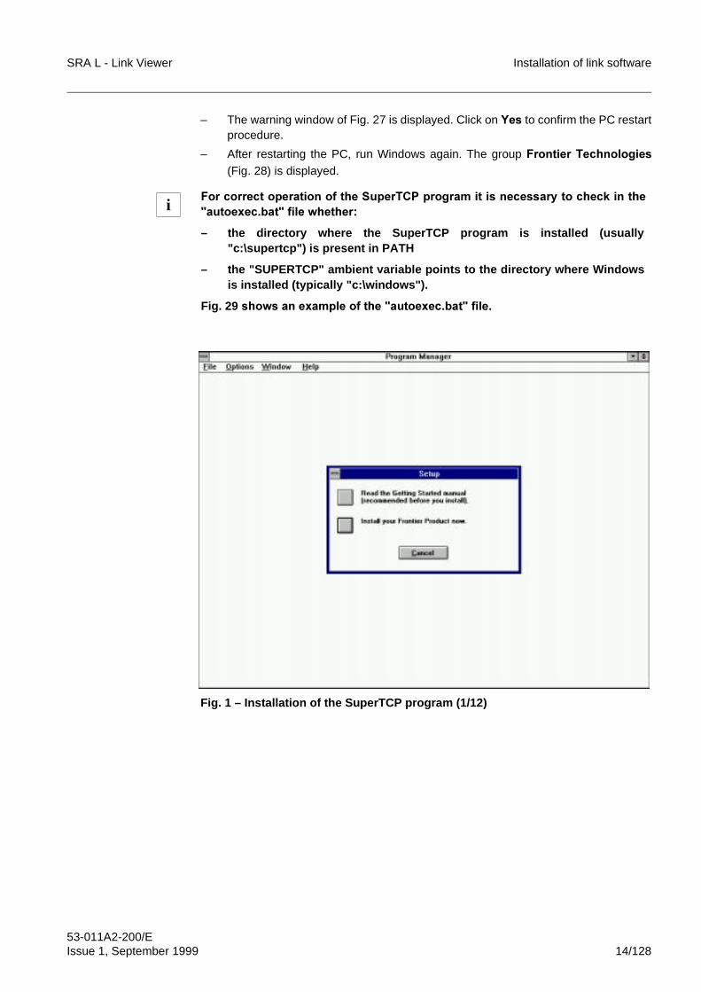
SRA L - Link Viewer Installation of link software
53-011A2-200/EIssue 1, September 1999 14/128
– The warning window of Fig. 27 is displayed. Click on <HV to confirm the PC restartprocedure.
– After restarting the PC, run Windows again. The group )URQWLHU�7HFKQRORJLHV(Fig. 28) is displayed.
Fig. 1 – Installation of the SuperTCP program (1/12)
)RU�FRUUHFW�RSHUDWLRQ�RI�WKH�6XSHU7&3�SURJUDP�LW�LV�QHFHVVDU\�WR�FKHFN�LQ�WKH�DXWRH[HF�EDW��ILOH�ZKHWKHU�
– the directory where the SuperTCP program is installed (usually"c:\supertcp") is present in PATH
– the "SUPERTCP" ambient variable points to the directory where Windowsis installed (typically "c:\windows").
Fig. 29 �VKRZV�DQ�H[DPSOH�RI�WKH��DXWRH[HF�EDW��ILOH�
i
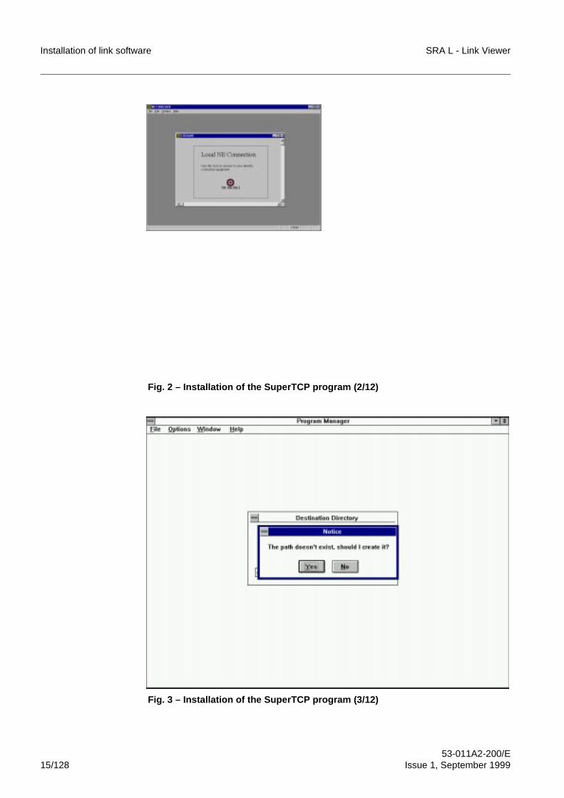
Installation of link software SRA L - Link Viewer
53-011A2-200/E15/128 Issue 1, September 1999
Fig. 2 – Installation of the SuperTCP program (2/12)
Fig. 3 – Installation of the SuperTCP program (3/12)
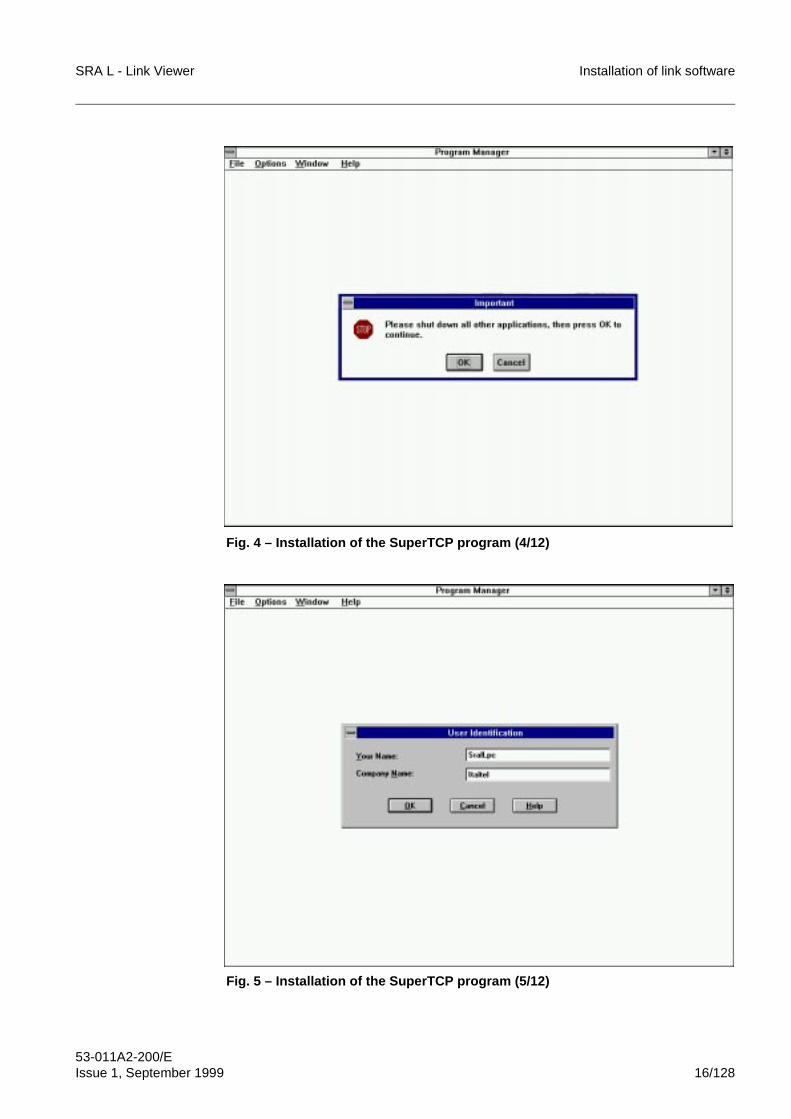
SRA L - Link Viewer Installation of link software
53-011A2-200/EIssue 1, September 1999 16/128
Fig. 4 – Installation of the SuperTCP program (4/12)
Fig. 5 – Installation of the SuperTCP program (5/12)
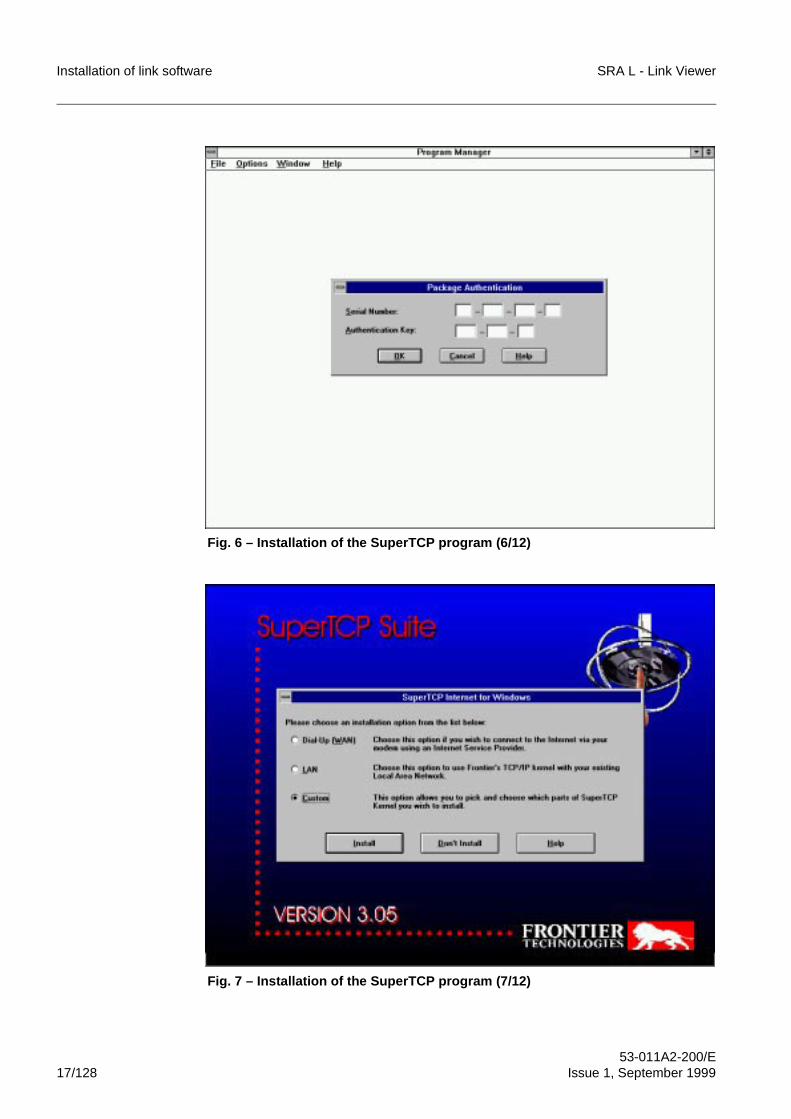
Installation of link software SRA L - Link Viewer
53-011A2-200/E17/128 Issue 1, September 1999
Fig. 6 – Installation of the SuperTCP program (6/12)
Fig. 7 – Installation of the SuperTCP program (7/12)
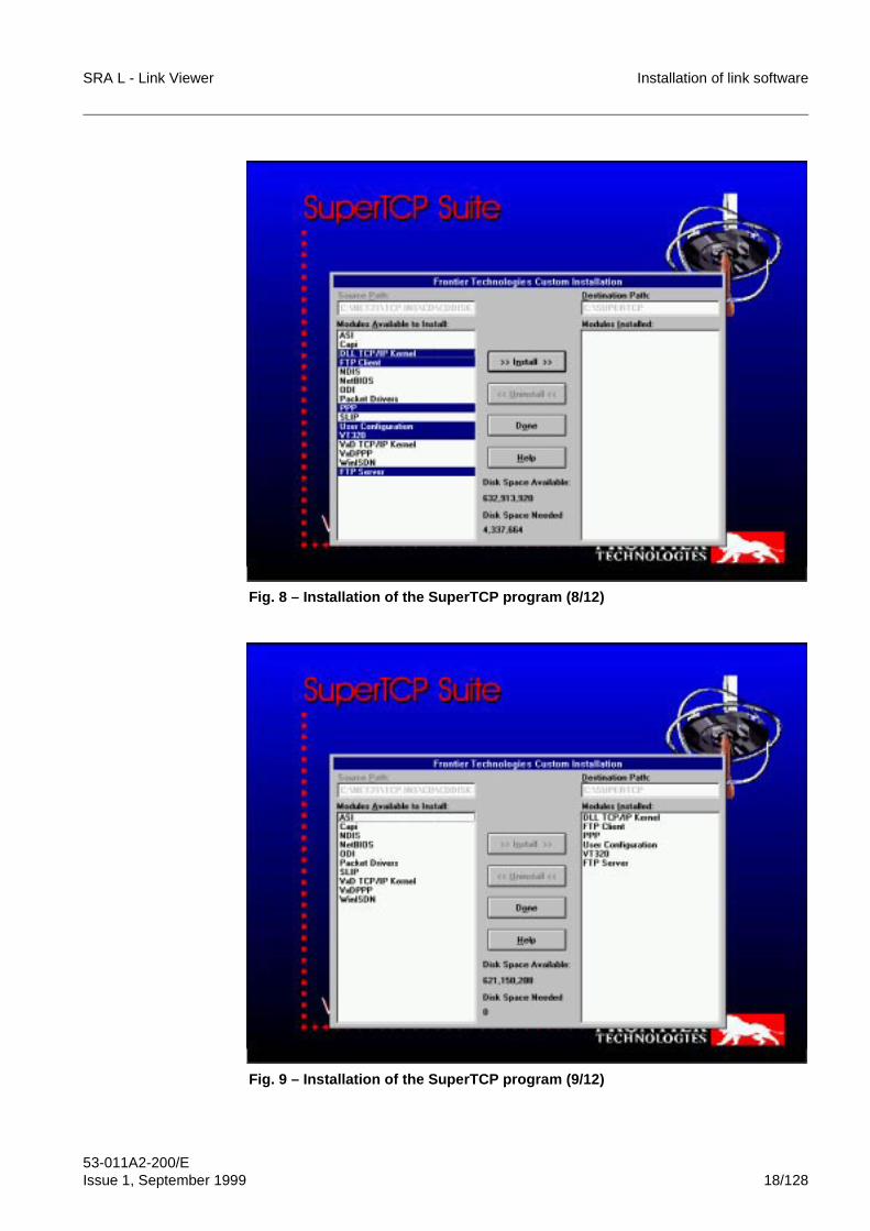
SRA L - Link Viewer Installation of link software
53-011A2-200/EIssue 1, September 1999 18/128
Fig. 8 – Installation of the SuperTCP program (8/12)
Fig. 9 – Installation of the SuperTCP program (9/12)
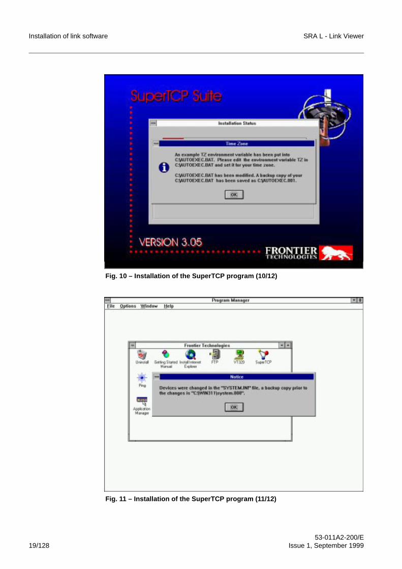
Installation of link software SRA L - Link Viewer
53-011A2-200/E19/128 Issue 1, September 1999
Fig. 10 – Installation of the SuperTCP program (10/12)
Fig. 11 – Installation of the SuperTCP program (11/12)
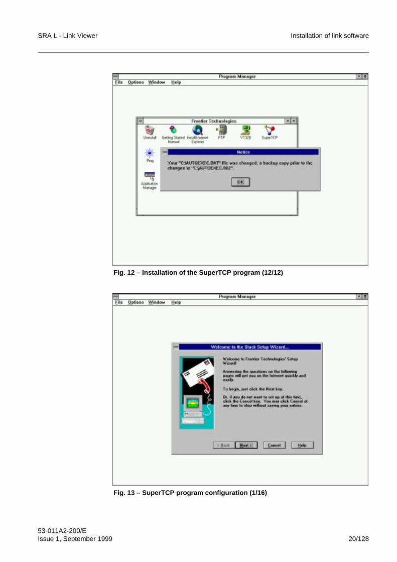
SRA L - Link Viewer Installation of link software
53-011A2-200/EIssue 1, September 1999 20/128
Fig. 12 – Installation of the SuperTCP program (12/12)
Fig. 13 – SuperTCP program configuration (1/16)
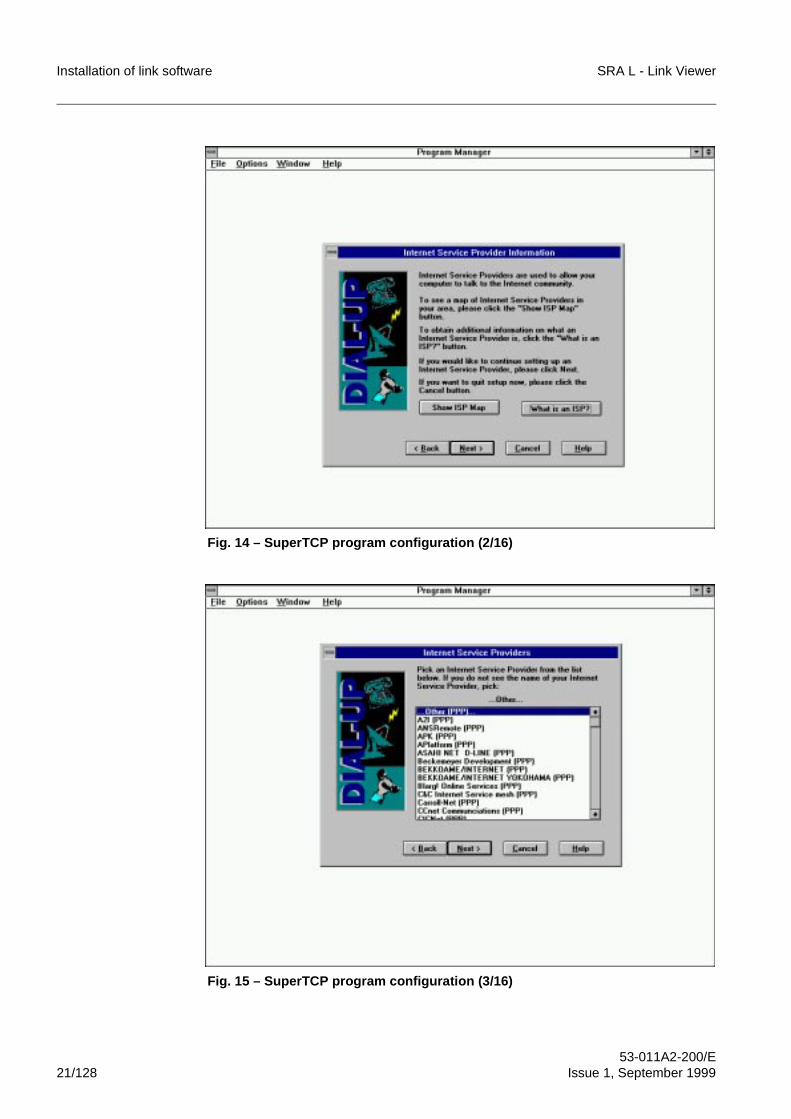
Installation of link software SRA L - Link Viewer
53-011A2-200/E21/128 Issue 1, September 1999
Fig. 14 – SuperTCP program configuration (2/16)
Fig. 15 – SuperTCP program configuration (3/16)
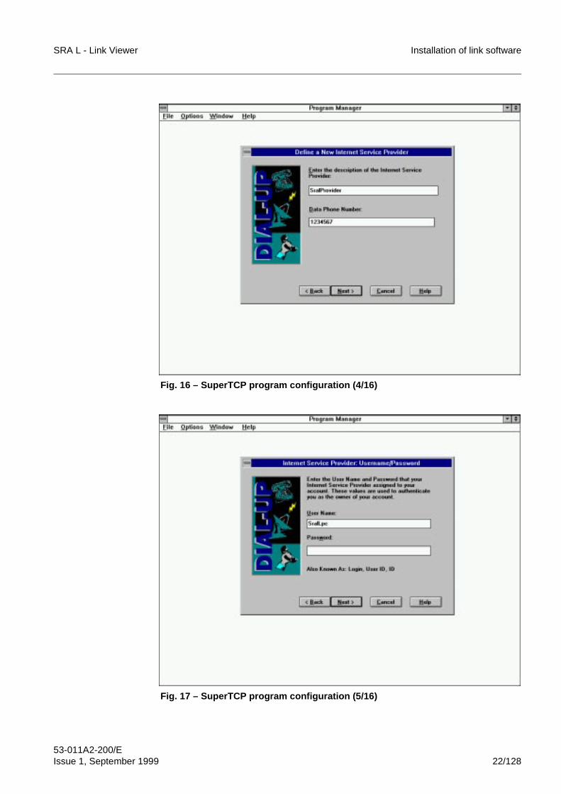
SRA L - Link Viewer Installation of link software
53-011A2-200/EIssue 1, September 1999 22/128
Fig. 16 – SuperTCP program configuration (4/16)
Fig. 17 – SuperTCP program configuration (5/16)
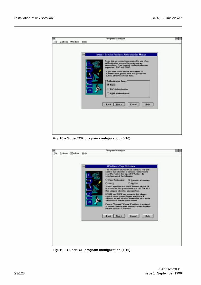
Installation of link software SRA L - Link Viewer
53-011A2-200/E23/128 Issue 1, September 1999
Fig. 18 – SuperTCP program configuration (6/16)
Fig. 19 – SuperTCP program configuration (7/16)
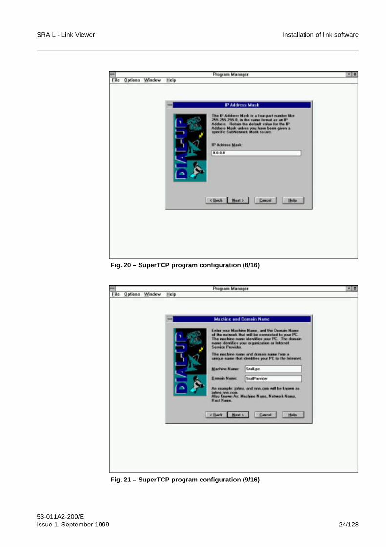
SRA L - Link Viewer Installation of link software
53-011A2-200/EIssue 1, September 1999 24/128
Fig. 20 – SuperTCP program configuration (8/16)
Fig. 21 – SuperTCP program configuration (9/16)
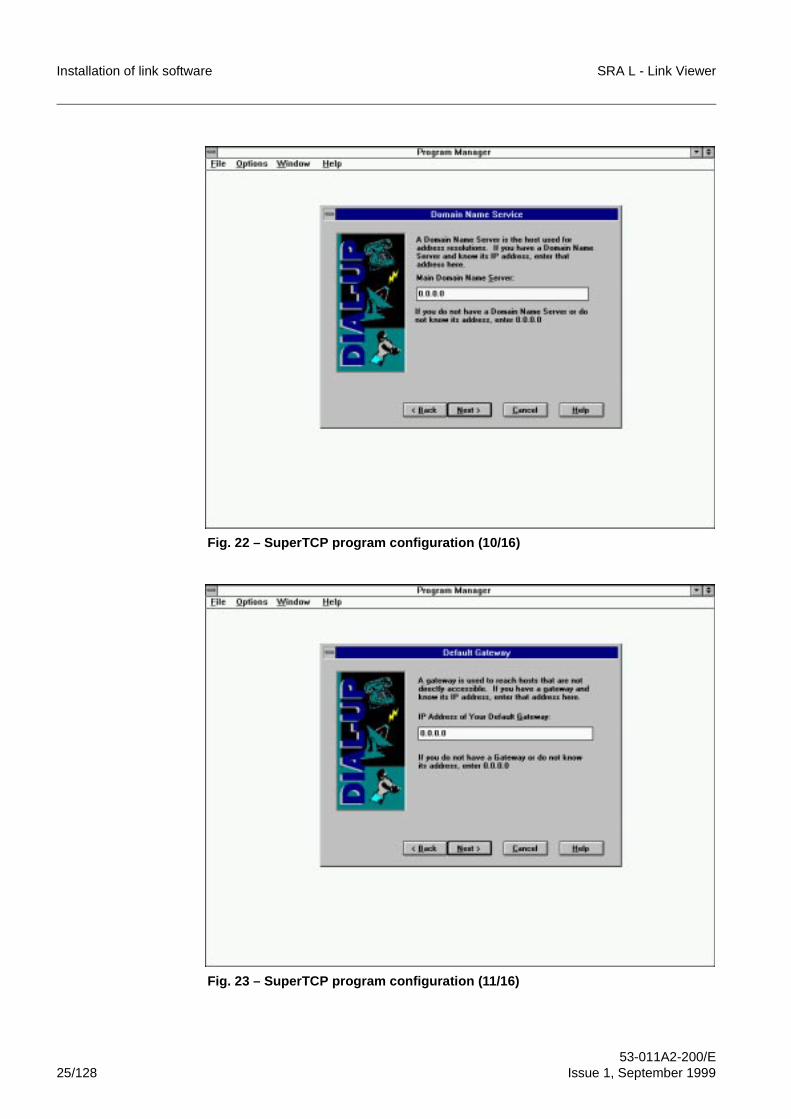
Installation of link software SRA L - Link Viewer
53-011A2-200/E25/128 Issue 1, September 1999
Fig. 22 – SuperTCP program configuration (10/16)
Fig. 23 – SuperTCP program configuration (11/16)
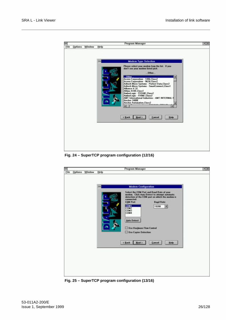
SRA L - Link Viewer Installation of link software
53-011A2-200/EIssue 1, September 1999 26/128
Fig. 24 – SuperTCP program configuration (12/16)
Fig. 25 – SuperTCP program configuration (13/16)
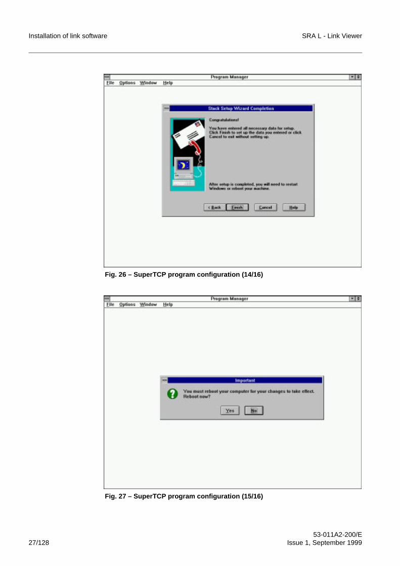
Installation of link software SRA L - Link Viewer
53-011A2-200/E27/128 Issue 1, September 1999
Fig. 26 – SuperTCP program configuration (14/16)
Fig. 27 – SuperTCP program configuration (15/16)
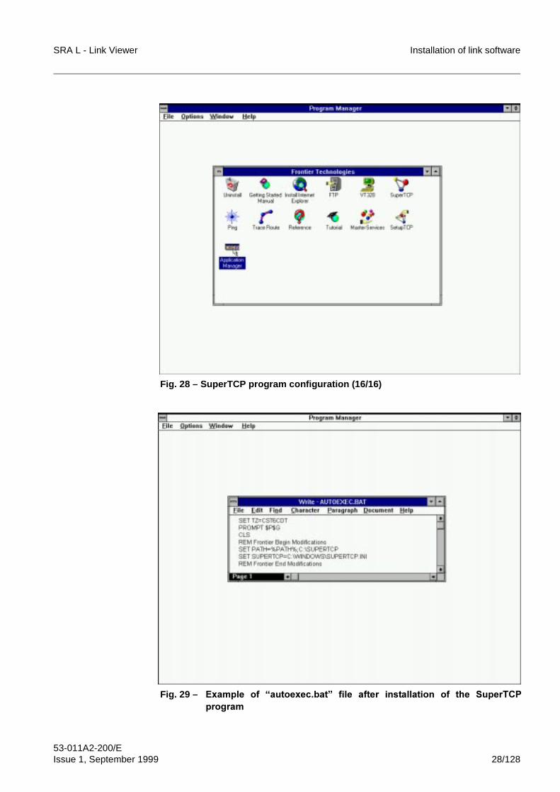
SRA L - Link Viewer Installation of link software
53-011A2-200/EIssue 1, September 1999 28/128
Fig. 28 – SuperTCP program configuration (16/16)
Fig. 29 – ([DPSOH� RI� ³DXWRH[HF�EDW´� ILOH� DIWHU� LQVWDOODWLRQ� RI� WKH� 6XSHU7&3SURJUDP
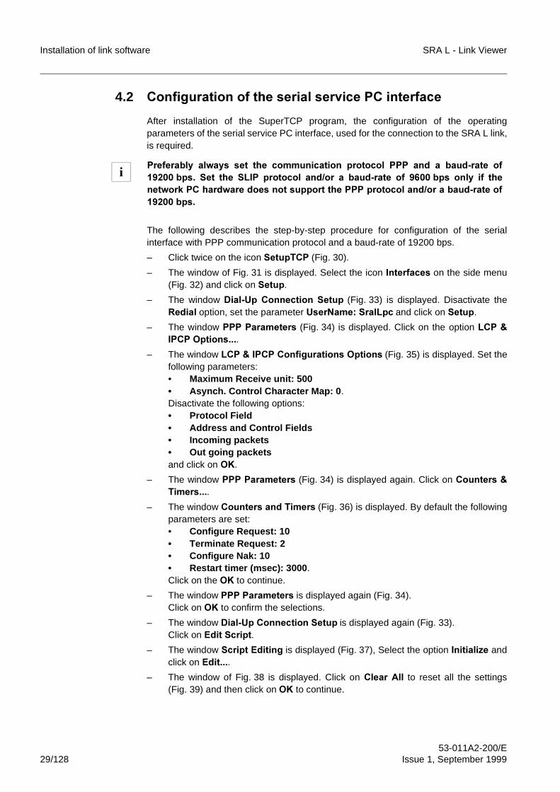
Installation of link software SRA L - Link Viewer
53-011A2-200/E29/128 Issue 1, September 1999
4.2 &RQILJXUDWLRQ�RI�WKH�VHULDO�VHUYLFH�3&�LQWHUIDFH
After installation of the SuperTCP program, the configuration of the operatingparameters of the serial service PC interface, used for the connection to the SRA L link,is required.
The following describes the step-by-step procedure for configuration of the serialinterface with PPP communication protocol and a baud-rate of 19200 bps.
– Click twice on the icon 6HWXS7&3 (Fig. 30).
– The window of Fig. 31 is displayed. Select the icon�,QWHUIDFHV on the side menu(Fig. 32) and click on 6HWXS.
– The window 'LDO�8S�&RQQHFWLRQ�6HWXS (Fig. 33) is displayed. Disactivate the5HGLDO option, set the parameter 8VHU1DPH��6UDO/SF and click on 6HWXS.
– The window 333�3DUDPHWHUV (Fig. 34) is displayed. Click on the�option /&3�,3&3�2SWLRQV���.
– The window /&3��,3&3�&RQILJXUDWLRQV�2SWLRQV (Fig. 35) is displayed. Set thefollowing parameters:• Maximum Receive unit: 500• Asynch. Control Character Map: 0 .Disactivate the following options:• Protocol Field• Address and Control Fields• Incoming packets• Out going packetsand click on 2..
– The window 333�3DUDPHWHUV (Fig. 34) is displayed again. Click on &RXQWHUV�7LPHUV���.
– The window &RXQWHUV�DQG�7LPHUV (Fig. 36) is displayed. By default the followingparameters are set:• Configure Request: 10• Terminate Request: 2• Configure Nak: 10• Restart timer (msec): 3000 .Click on the 2. to continue.
– The window 333�3DUDPHWHUV is displayed again (Fig. 34). Click on 2. to confirm the selections.
– The window 'LDO�8S�&RQQHFWLRQ�6HWXS is displayed again (Fig. 33).Click on (GLW�6FULSW.
– The window 6FULSW�(GLWLQJ is displayed (Fig. 37), Select the option ,QLWLDOL]H andclick on (GLW���.
– The window of Fig. 38 is displayed. Click on &OHDU�$OO to reset all the settings(Fig. 39) and then click on 2. to continue.
3UHIHUDEO\� DOZD\V� VHW� WKH� FRPPXQLFDWLRQ� SURWRFRO� 333� DQG� D� EDXG�UDWH� RI����� ESV�� 6HW� WKH� 6/,3� SURWRFRO� DQG�RU� D� EDXG�UDWH� RI� ���� ESV� RQO\� LI� WKHQHWZRUN�3&�KDUGZDUH�GRHV�QRW�VXSSRUW�WKH�333�SURWRFRO�DQG�RU�D�EDXG�UDWH�RI������ESV�
i
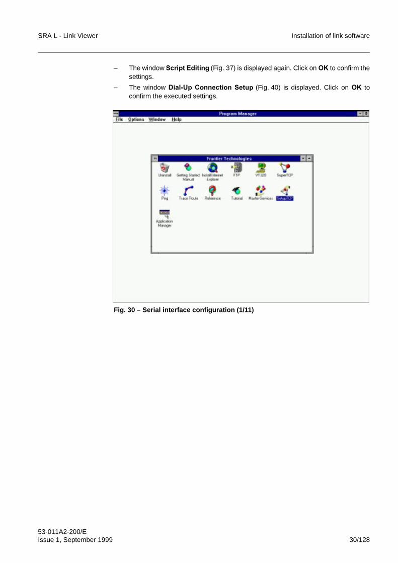
SRA L - Link Viewer Installation of link software
53-011A2-200/EIssue 1, September 1999 30/128
– The window 6FULSW�(GLWLQJ (Fig. 37) is displayed again. Click on 2. to confirm thesettings.
– The window 'LDO�8S�&RQQHFWLRQ�6HWXS (Fig. 40) is displayed. Click on 2. toconfirm the executed settings.
Fig. 30 – Serial interface configuration (1/11)
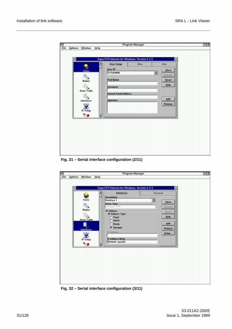
Installation of link software SRA L - Link Viewer
53-011A2-200/E31/128 Issue 1, September 1999
Fig. 31 – Serial interface configuration (2/11)
Fig. 32 – Serial interface configuration (3/11)
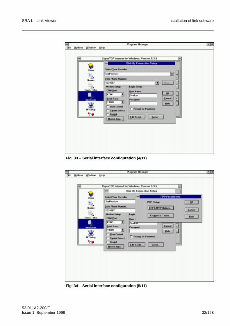
SRA L - Link Viewer Installation of link software
53-011A2-200/EIssue 1, September 1999 32/128
Fig. 33 – Serial interface configuration (4/11)
Fig. 34 – Serial interface configuration (5/11)
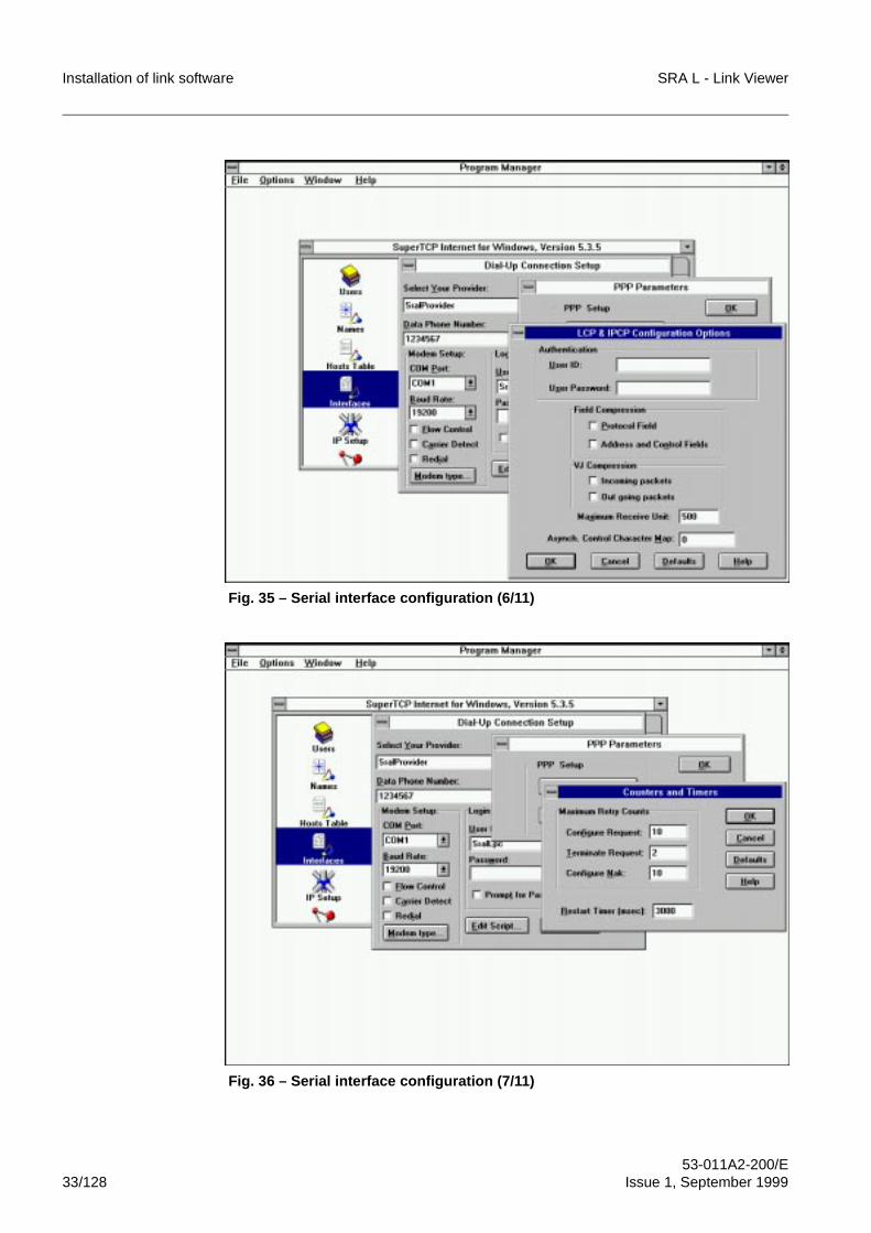
Installation of link software SRA L - Link Viewer
53-011A2-200/E33/128 Issue 1, September 1999
Fig. 35 – Serial interface configuration (6/11)
Fig. 36 – Serial interface configuration (7/11)
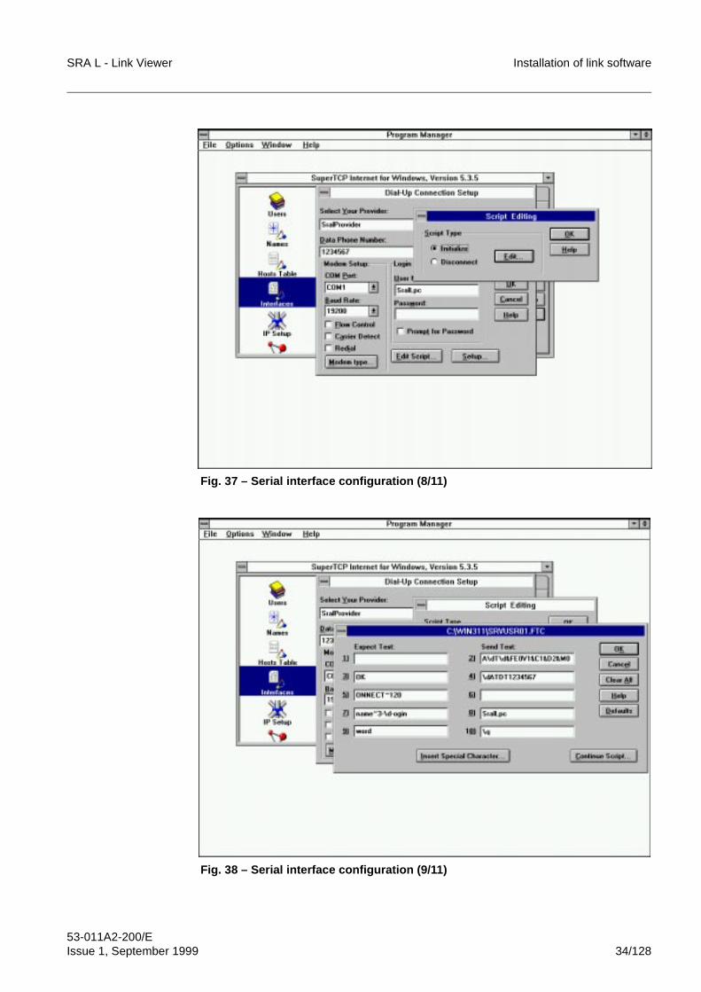
SRA L - Link Viewer Installation of link software
53-011A2-200/EIssue 1, September 1999 34/128
Fig. 37 – Serial interface configuration (8/11)
Fig. 38 – Serial interface configuration (9/11)
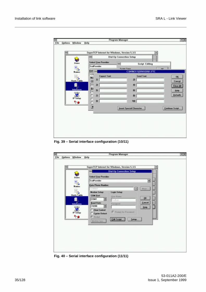
Installation of link software SRA L - Link Viewer
53-011A2-200/E35/128 Issue 1, September 1999
Fig. 39 – Serial interface configuration (10/11)
Fig. 40 – Serial interface configuration (11/11)
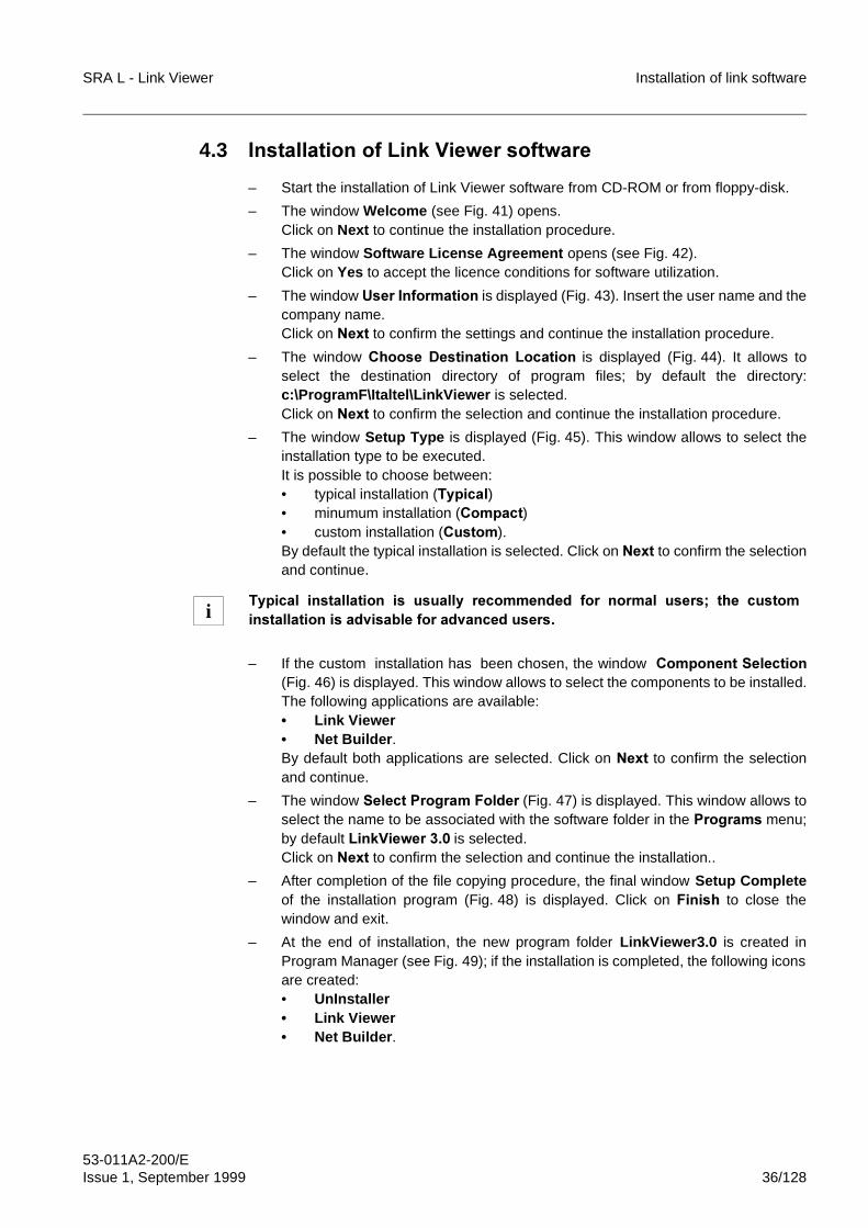
SRA L - Link Viewer Installation of link software
53-011A2-200/EIssue 1, September 1999 36/128
4.3 ,QVWDOODWLRQ�RI�/LQN�9LHZHU�VRIWZDUH
– Start the installation of Link Viewer software from CD-ROM or from floppy-disk.
– The window Welcome (see Fig. 41) opens. Click on Next to continue the installation procedure.
– The window Software License Agreement opens (see Fig. 42).Click on Yes to accept the licence conditions for software utilization.
– The window 8VHU�,QIRUPDWLRQ is displayed (Fig. 43). Insert the user name and thecompany name.Click on 1H[W to confirm the settings and continue the installation procedure.
– The window &KRRVH� 'HVWLQDWLRQ� /RFDWLRQ is displayed (Fig. 44). It allows toselect the destination directory of program files; by default the directory:c:\ProgramF\Italtel\LinkViewer�is selected.Click on 1H[W to confirm the selection and continue the installation procedure.
– The window Setup Type is displayed (Fig. 45). This window allows to select theinstallation type to be executed.It is possible to choose between:• typical installation (7\SLFDO)• minumum installation (&RPSDFW)• custom installation (&XVWRP).By default the typical installation is selected. Click on 1H[W to confirm the selectionand continue.
– If the custom installation has been chosen, the window &RPSRQHQW�6HOHFWLRQ(Fig. 46) is displayed. This window allows to select the components to be installed.The following applications are available:• Link Viewer• Net Builder .By default both applications are selected. Click on 1H[W to confirm the selectionand continue.
– The�window 6HOHFW�3URJUDP�)ROGHU (Fig. 47) is displayed. This window allows toselect the name to be associated with the software folder in the 3URJUDPV menu;by default /LQN9LHZHU�����is selected.Click on 1H[W to confirm the selection and continue the installation..
– After completion of the file copying procedure, the final window Setup Completeof the installation program (Fig. 48) is displayed. Click on� )LQLVK to close thewindow and exit.
– At the end of installation, the new program folder LinkViewer3.0 is created inProgram Manager (see Fig. 49); if the installation is completed, the following iconsare created:• UnInstaller• Link Viewer• Net Builder .
7\SLFDO� LQVWDOODWLRQ� LV� XVXDOO\� UHFRPPHQGHG� IRU� QRUPDO� XVHUV�� WKH� FXVWRPLQVWDOODWLRQ�LV�DGYLVDEOH�IRU�DGYDQFHG�XVHUV�i
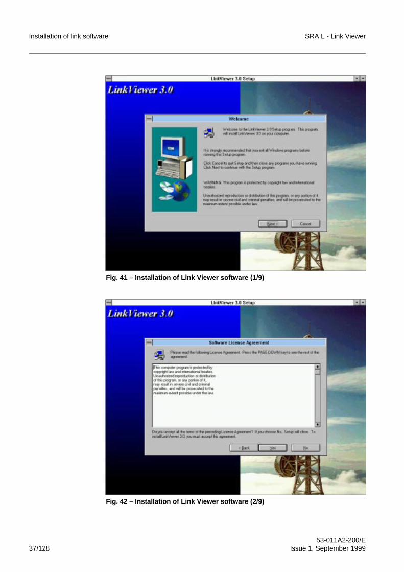
Installation of link software SRA L - Link Viewer
53-011A2-200/E37/128 Issue 1, September 1999
Fig. 41 – Installation of Link Viewer software (1/9)
Fig. 42 – Installation of Link Viewer software (2/9)
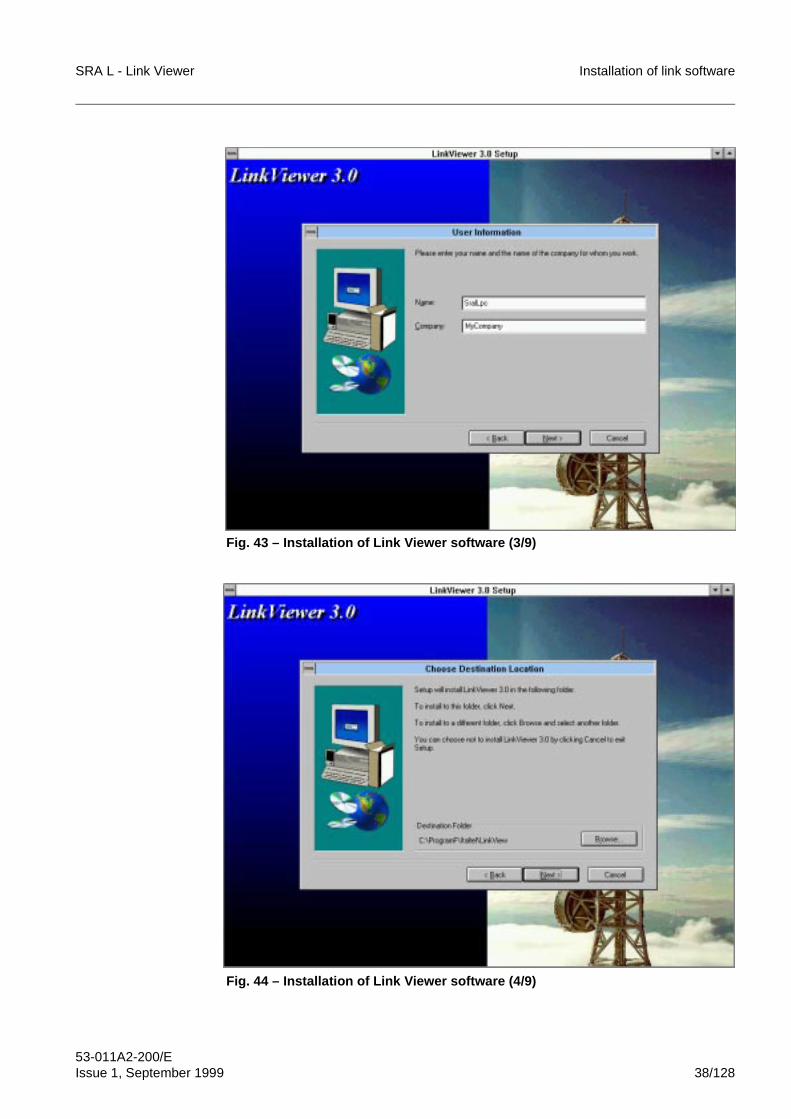
SRA L - Link Viewer Installation of link software
53-011A2-200/EIssue 1, September 1999 38/128
Fig. 43 – Installation of Link Viewer software (3/9)
Fig. 44 – Installation of Link Viewer software (4/9)
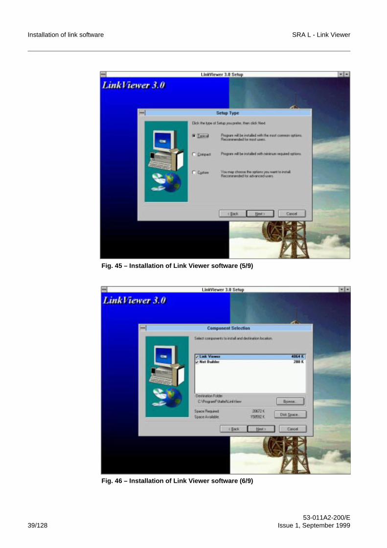
Installation of link software SRA L - Link Viewer
53-011A2-200/E39/128 Issue 1, September 1999
Fig. 45 – Installation of Link Viewer software (5/9)
Fig. 46 – Installation of Link Viewer software (6/9)
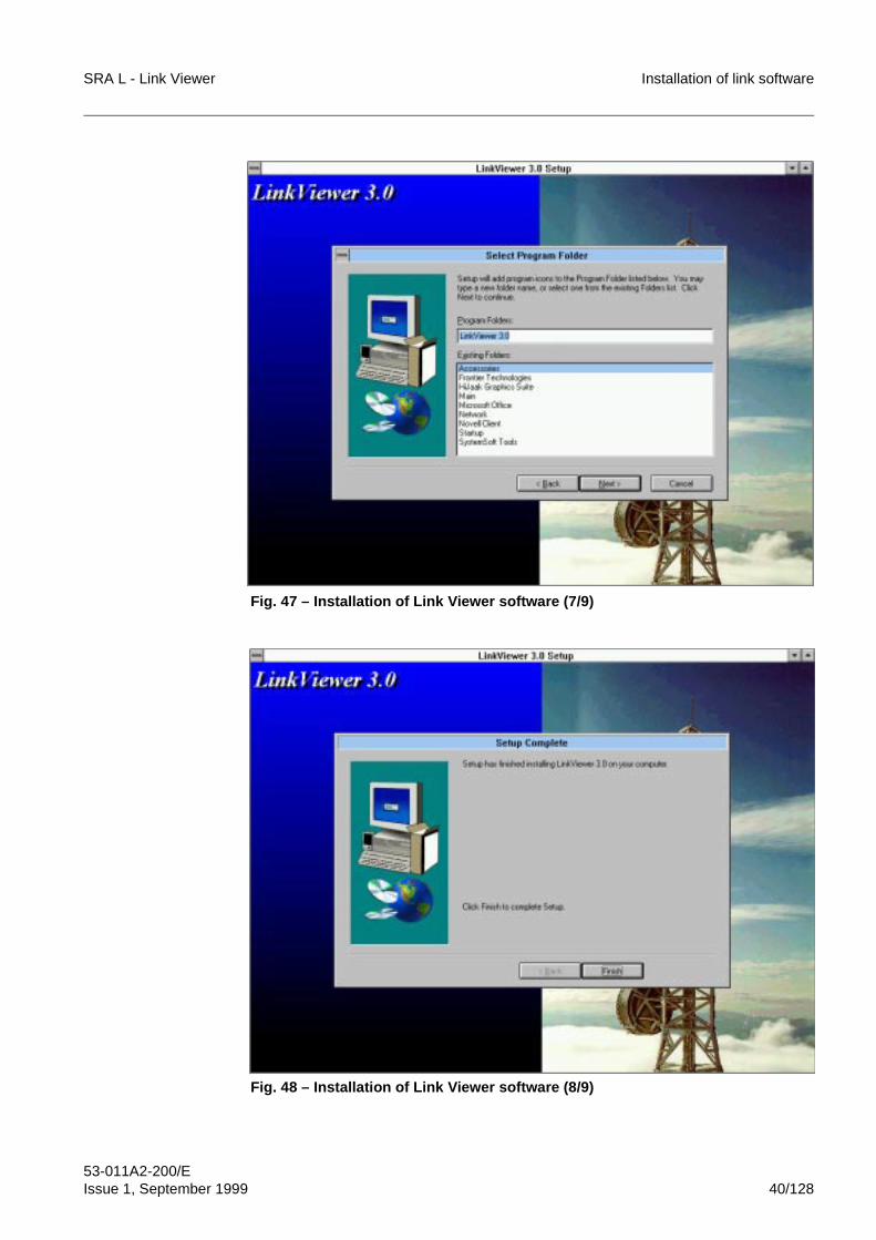
SRA L - Link Viewer Installation of link software
53-011A2-200/EIssue 1, September 1999 40/128
Fig. 47 – Installation of Link Viewer software (7/9)
Fig. 48 – Installation of Link Viewer software (8/9)
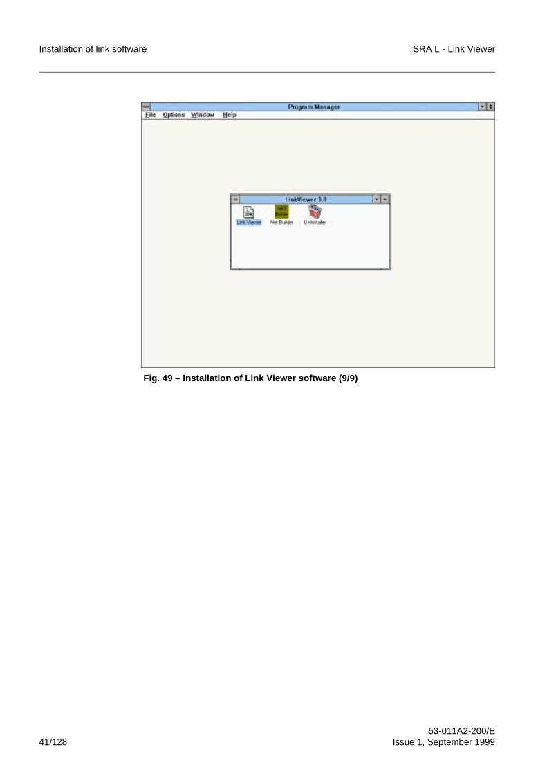
Installation of link software SRA L - Link Viewer
53-011A2-200/E41/128 Issue 1, September 1999
Fig. 49 – Installation of Link Viewer software (9/9)
SRA L - Link Viewer Installation of link software
53-011A2-200/EIssue 1, September 1999 42/128
4.4 Installation of SRA L software plugs-in
Once the LinkViewer software has been succesfully installed, we must install the plug-insoftware for the different SRA Ls.It is necessary to install only the plug-in software concerning the SRA Ls used in the link.
The Link Viewer program can recognize and, then, manage only the SRA Ls, whoseplug-in has been installed.The installation of a software plug-in causes:
– the capacity for the Link Viewer program to manage the corresponding type ofSRA L;
– the addition of the Help program, corresponding to this SRA L managementapplication program, in the Help menu of Link Viewer program.
To install a plug-in software, we must start the relative installation executable file fromCD-ROM or from floppy disk and, then, follow the instructions shown on the video.The installation program automatically copies the plug-in files in the same directory inwhich the Link Viewer software is installed.
After the plug-in installation, we must exit and, then, restart the Link Viewer program (ifit was already functioning) to apply the changes.
To install the plug-in software, the LinkViewer program must be alreadyinstalled; otherwise, install first the LinkViewer program and, then, the plug-in(see par. 4.3).
The installation procedure for each plug-in is described, in every detail, in thecorresponding SRA L OMN Manual.
i
i
Installation of link software SRA L - Link Viewer
53-011A2-200/E43/128 Issue 1, September 1999
5 62)7:$5(� ,167$//$7,21� ,1� :,1'2:6���17����
For the installation in Windows 95/NT it is necessary to:
– use the TCP/IP protocol to configure and activate the connection between theservice PC and the SRA L link, using the functions available in Windows 95/NTitself; the connection can be made by means of a serial RS-232C or Ethernetinterface
– install link software: Link Viewer program and, if requested, the SuperTCP program(optional)
– install the plug-in software for the different SRA Ls.
5.1 &RQILJXUDWLRQ�RI�WKH�FRQQHFWLRQ�ZLWK�WKH�65$�/�OLQNE\�PHDQV�RI�D�VHULDO�56����&�LQWHUIDFH�LQ�:LQGRZV���
For the configuration of a connection with the SRA L link through a serial RS-232Cinterface, the following operations are required:
– check whether software requirements are met
– installation of the direct connection via cable
– creation and configuration of the dial-up connection with the SRA L link
– configuration of the TCP/IP protocol.
)RU�VRIWZDUH�LQVWDOODWLRQ�XQGHU�:LQGRZV����17�WKH�:LQGRZV����17�LQVWDOODWLRQ&'�520� PXVW� EH� XVHG�� )RU� FRQQHFWLRQV� YLD� (WKHUQHW� LQWHUIDFH� DOVR� WKHIORSS\�GLVN�&'�520� ZLWK� WKH� QHWZRUN� FDUG� GULYHUV� PXVW� EH� LQVWDOOHG� RQ� WKHQHWZRUN�3&�
The SRA L plug-in software installation must be executed after that the LinkViewer software has been succesfully installed.
8QGHU�:LQGRZV����WKH�IROORZLQJ�VRIWZDUH�FRPSRQHQWV�PXVW�EH�LQVWDOOHG�RQ�WKHQHWZRUN�3&�
– direct cable connection
– TCP/IP communication protocol.
Otherwise the software must be installed using the Windows 95 installationCD-ROM.
i
i
i
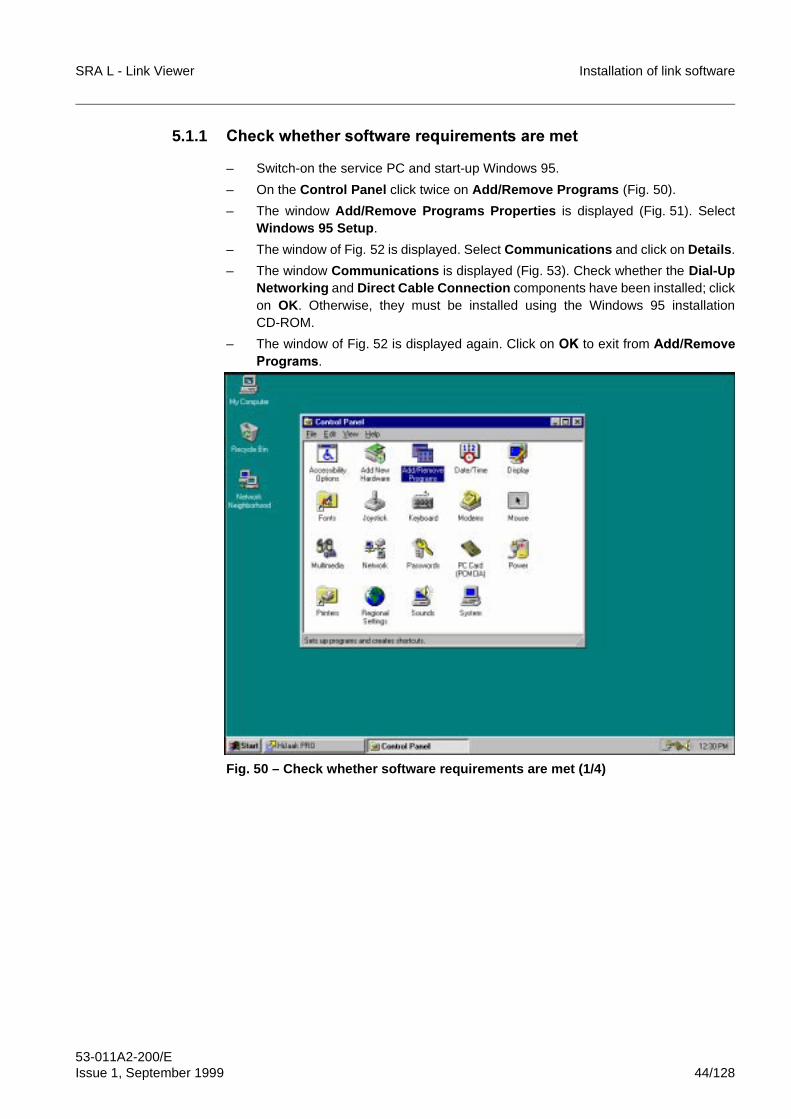
SRA L - Link Viewer Installation of link software
53-011A2-200/EIssue 1, September 1999 44/128
5.1.1 &KHFN�ZKHWKHU�VRIWZDUH�UHTXLUHPHQWV�DUH�PHW
– Switch-on the service PC and start-up Windows 95.
– On the Control Panel click twice on Add/Remove Programs (Fig. 50).
– The window Add/Remove Programs Properties is displayed (Fig. 51). SelectWindows 95 Setup.
– The window of Fig. 52 is displayed. Select Communications and click on Details.
– The window Communications is displayed (Fig. 53). Check whether the Dial-UpNetworking and Direct Cable Connection components have been installed; clickon OK. Otherwise, they must be installed using the Windows 95 installationCD-ROM.
– The window of Fig. 52 is displayed again. Click on 2. to exit from $GG�5HPRYH3URJUDPV.
Fig. 50 – Check whether software requirements are met (1/4)
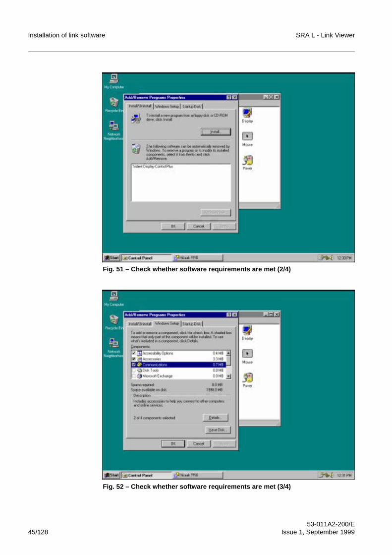
Installation of link software SRA L - Link Viewer
53-011A2-200/E45/128 Issue 1, September 1999
Fig. 51 – Check whether software requirements are met (2/4)
Fig. 52 – Check whether software requirements are met (3/4)
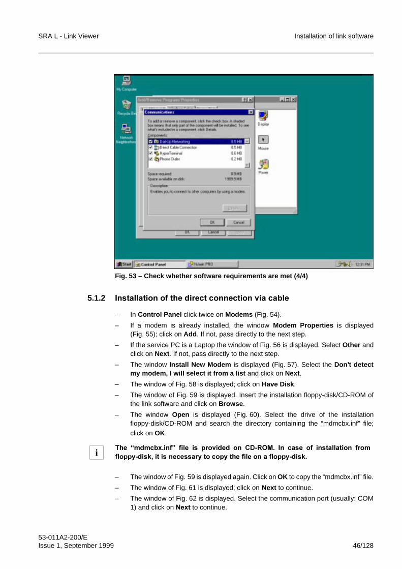
SRA L - Link Viewer Installation of link software
53-011A2-200/EIssue 1, September 1999 46/128
Fig. 53 – Check whether software requirements are met (4/4)
5.1.2 ,QVWDOODWLRQ�RI�WKH�GLUHFW�FRQQHFWLRQ�YLD�FDEOH
– In Control Panel click twice on Modems (Fig. 54).
– If a modem is already installed, the window Modem Properties is displayed(Fig. 55); click on Add. If not, pass directly to the next step.
– If the service PC is a Laptop the window of Fig. 56 is displayed. Select Other andclick on Next. If not, pass directly to the next step.
– The window Install New Modem is displayed (Fig. 57). Select the Don’t detectmy modem, I will select it from a list and click on Next.
– The window of Fig. 58 is displayed; click on Have Disk.
– The window of Fig. 59 is displayed. Insert the installation floppy-disk/CD-ROM ofthe link software and click on Browse.
– The window Open is displayed (Fig. 60). Select the drive of the installationfloppy-disk/CD-ROM and search the directory containing the “mdmcbx.inf” file;
click on OK.
– The window of Fig. 59 is displayed again. Click on OK to copy the “mdmcbx.inf” file.
– The window of Fig. 61 is displayed; click on Next to continue.
– The window of Fig. 62 is displayed. Select the communication port (usually: COM1) and click on 1H[W to continue.
7KH� ³PGPFE[�LQI´� ILOH� LV� SURYLGHG� RQ� &'�520�� ,Q� FDVH� RI� LQVWDOODWLRQ� IURPIORSS\�GLVN��LW�LV�QHFHVVDU\�WR�FRS\�WKH�ILOH�RQ�D�IORSS\�GLVN�i
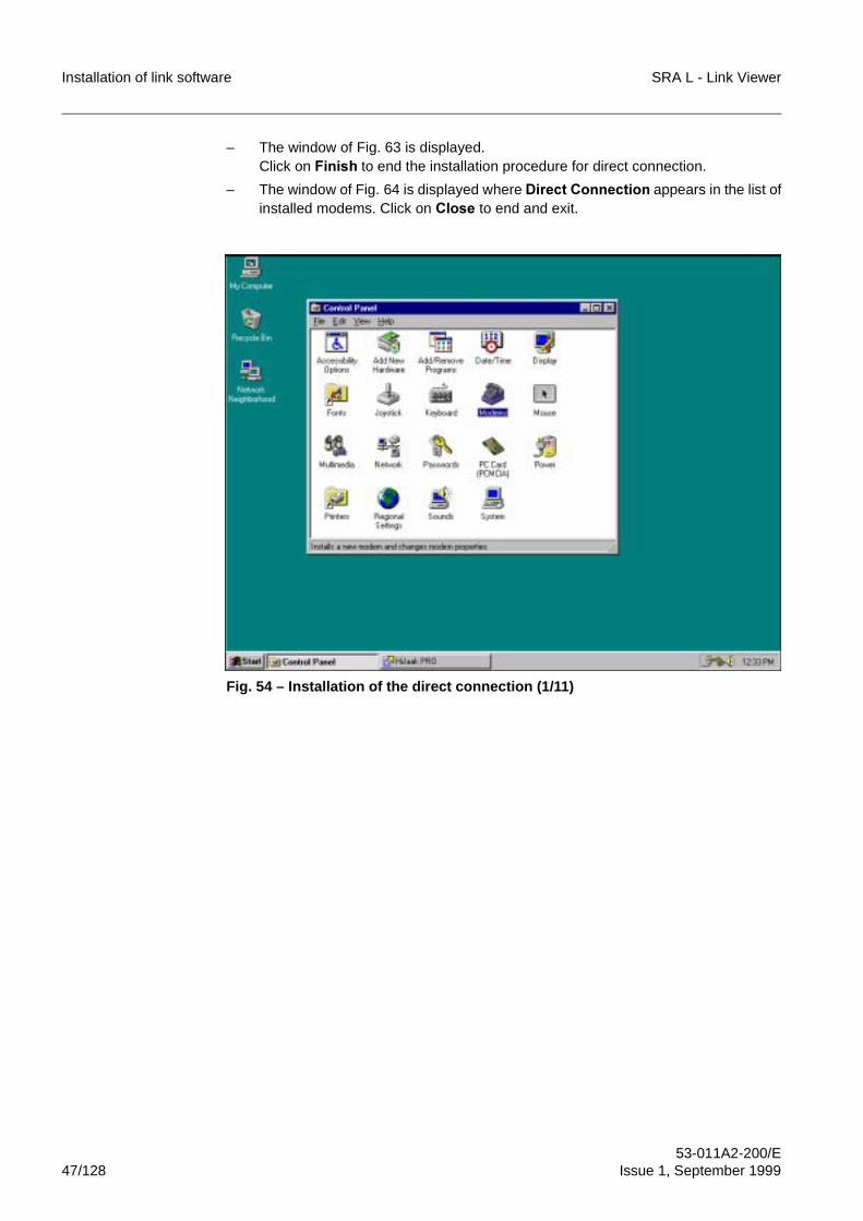
Installation of link software SRA L - Link Viewer
53-011A2-200/E47/128 Issue 1, September 1999
– The window of Fig. 63 is displayed. Click on )LQLVK to end the installation procedure for direct connection.
– The window of Fig. 64 is displayed where 'LUHFW�&RQQHFWLRQ appears in the list ofinstalled modems. Click on &ORVH to end and exit.
Fig. 54 – Installation of the direct connection (1/11)
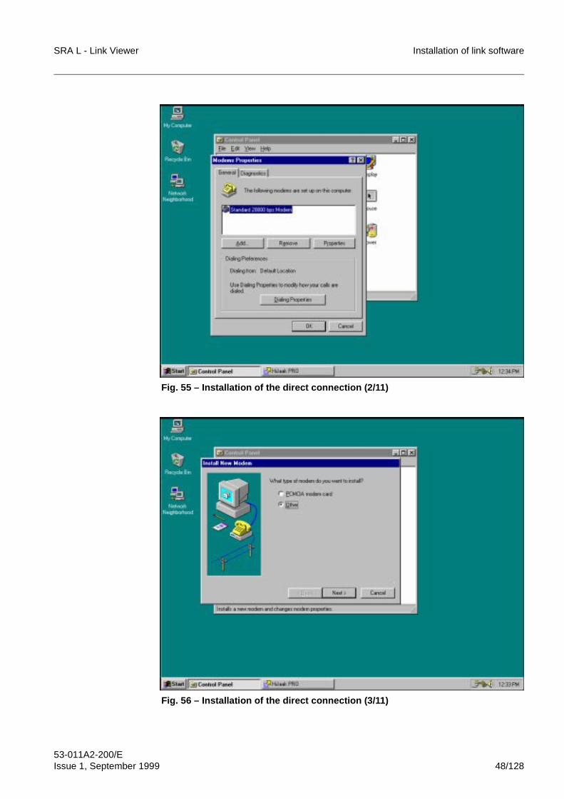
SRA L - Link Viewer Installation of link software
53-011A2-200/EIssue 1, September 1999 48/128
Fig. 55 – Installation of the direct connection (2/11)
Fig. 56 – Installation of the direct connection (3/11)
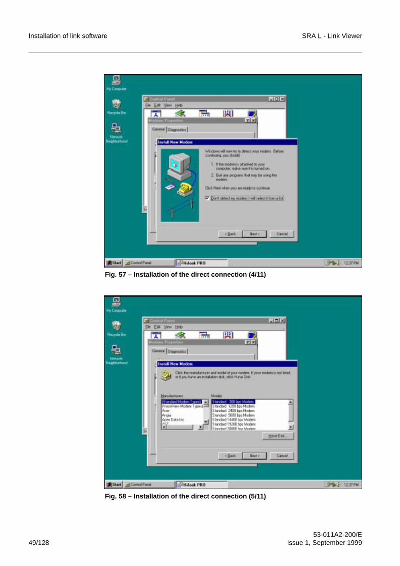
Installation of link software SRA L - Link Viewer
53-011A2-200/E49/128 Issue 1, September 1999
Fig. 57 – Installation of the direct connection (4/11)
Fig. 58 – Installation of the direct connection (5/11)
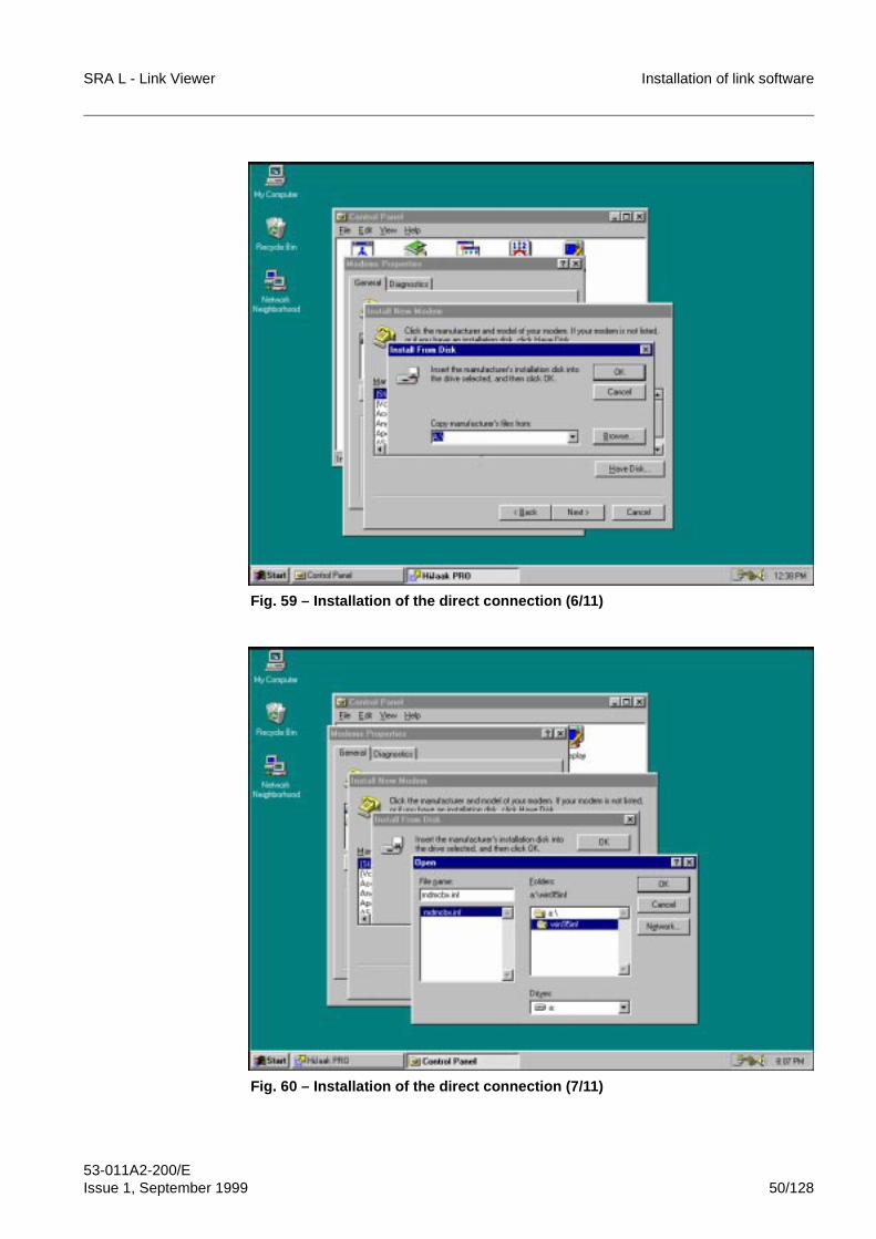
SRA L - Link Viewer Installation of link software
53-011A2-200/EIssue 1, September 1999 50/128
Fig. 59 – Installation of the direct connection (6/11)
Fig. 60 – Installation of the direct connection (7/11)
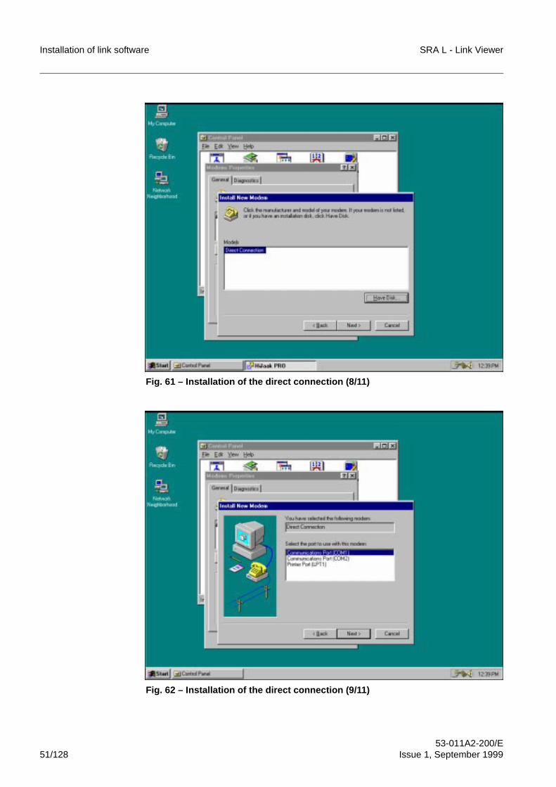
Installation of link software SRA L - Link Viewer
53-011A2-200/E51/128 Issue 1, September 1999
Fig. 61 – Installation of the direct connection (8/11)
Fig. 62 – Installation of the direct connection (9/11)
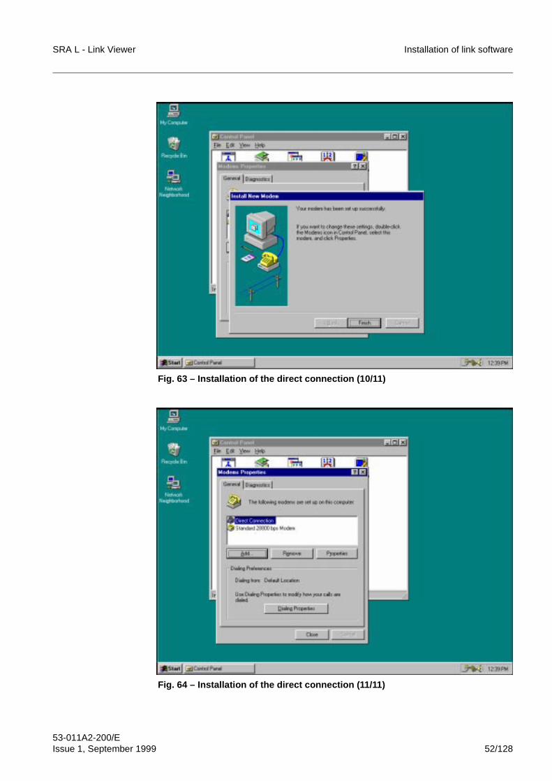
SRA L - Link Viewer Installation of link software
53-011A2-200/EIssue 1, September 1999 52/128
Fig. 63 – Installation of the direct connection (10/11)
Fig. 64 – Installation of the direct connection (11/11)
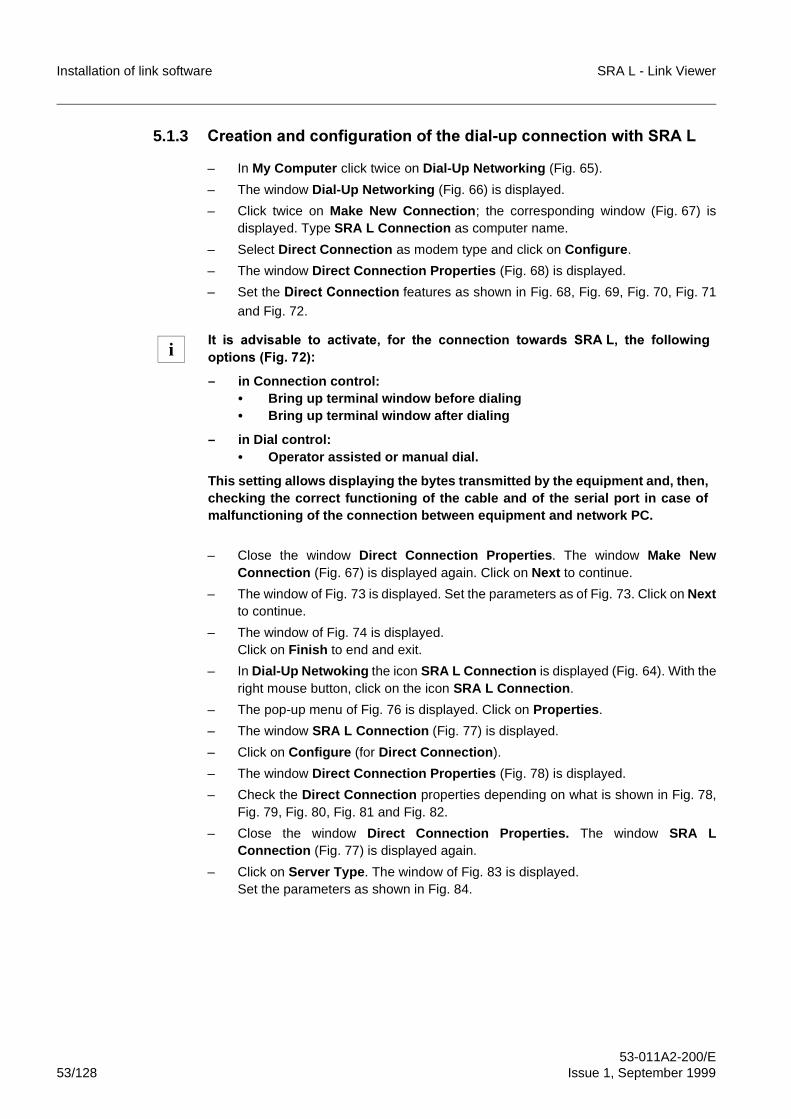
Installation of link software SRA L - Link Viewer
53-011A2-200/E53/128 Issue 1, September 1999
5.1.3 &UHDWLRQ�DQG�FRQILJXUDWLRQ�RI�WKH�GLDO�XS�FRQQHFWLRQ�ZLWK�65$�/
– In My Computer click twice on Dial-Up Networking (Fig. 65).
– The window Dial-Up Networking (Fig. 66) is displayed.
– Click twice on Make New Connection; the corresponding window (Fig. 67) isdisplayed. Type SRA L Connection as computer name.
– Select Direct Connection as modem type and click on Configure.
– The window Direct Connection Properties (Fig. 68) is displayed.
– Set the 'LUHFW�&RQQHFWLRQ features as shown in Fig. 68, Fig. 69, Fig. 70, Fig. 71
and Fig. 72.
– Close the window Direct Connection Properties. The window Make NewConnection (Fig. 67) is displayed again. Click on Next to continue.
– The window of Fig. 73 is displayed. Set the parameters as of Fig. 73. Click on Nextto continue.
– The window of Fig. 74 is displayed.Click on Finish to end and exit.
– In Dial-Up Netwoking the icon SRA L Connection is displayed (Fig. 64). With theright mouse button, click on the icon SRA L Connection.
– The pop-up menu of Fig. 76 is displayed. Click on Properties.
– The window SRA L Connection (Fig. 77) is displayed.
– Click on Configure (for Direct Connection).
– The window Direct Connection Properties (Fig. 78) is displayed.
– Check the Direct Connection properties depending on what is shown in Fig. 78,Fig. 79, Fig. 80, Fig. 81 and Fig. 82.
– Close the window Direct Connection Properties. The window SRA LConnection (Fig. 77) is displayed again.
– Click on Server Type. The window of Fig. 83 is displayed.Set the parameters as shown in Fig. 84.
,W� LV� DGYLVDEOH� WR� DFWLYDWH�� IRU� WKH� FRQQHFWLRQ� WRZDUGV� 65$ /�� WKH� IROORZLQJRSWLRQV��)LJ� ����
– in Connection control:• Bring up terminal window before dialing• Bring up terminal window after dialing
– in Dial control:• Operator assisted or manual dial.
This setting allows displaying the bytes transmitted by the equipment and, then,checking the correct functioning of the cable and of the serial port in case ofmalfunctioning of the connection between equipment and network PC.
i
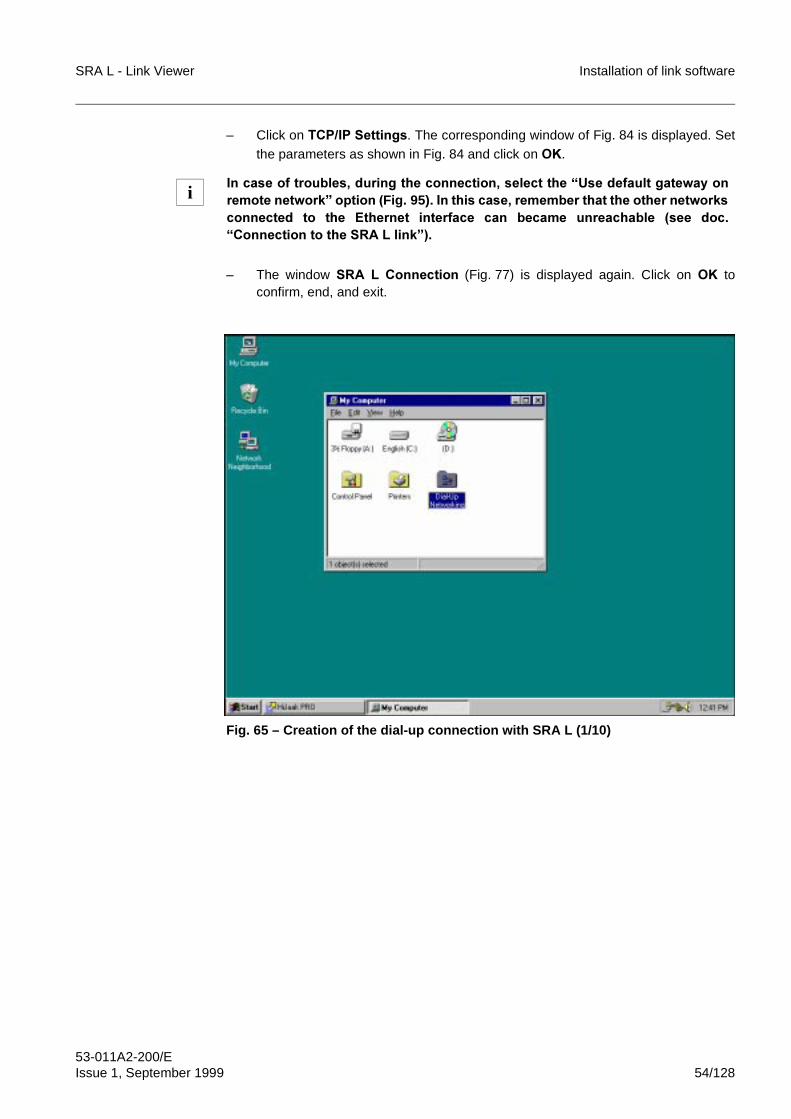
SRA L - Link Viewer Installation of link software
53-011A2-200/EIssue 1, September 1999 54/128
– Click on�7&3�,3 6HWWLQJV. The corresponding window of Fig. 84 is displayed. Setthe parameters as shown in Fig. 84 and click on 2..
– The window 65$� /� &RQQHFWLRQ� (Fig. 77) is displayed again. Click on 2. toconfirm, end, and exit.
Fig. 65 – Creation of the dial-up connection with SRA L (1/10)
,Q�FDVH�RI�WURXEOHV��GXULQJ�WKH�FRQQHFWLRQ��VHOHFW�WKH�³8VH�GHIDXOW�JDWHZD\�RQUHPRWH�QHWZRUN´�RSWLRQ��Fig. 95) ��,Q�WKLV�FDVH��UHPHPEHU�WKDW�WKH�RWKHU�QHWZRUNVFRQQHFWHG� WR� WKH� (WKHUQHW� LQWHUIDFH� FDQ� EHFDPH� XQUHDFKDEOH� �VHH� GRF�³&RQQHFWLRQ�WR�WKH�65$ /�OLQN´��
i
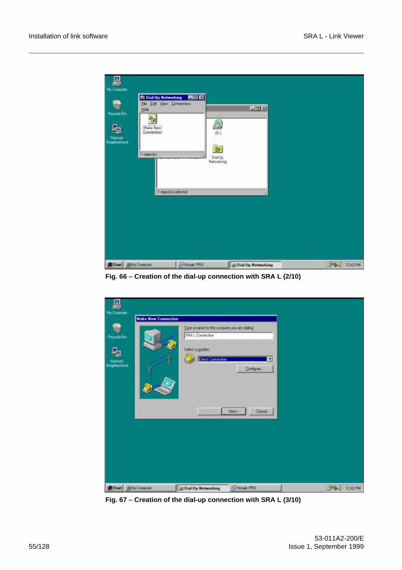
Installation of link software SRA L - Link Viewer
53-011A2-200/E55/128 Issue 1, September 1999
Fig. 66 – Creation of the dial-up connection with SRA L (2/10)
Fig. 67 – Creation of the dial-up connection with SRA L (3/10)
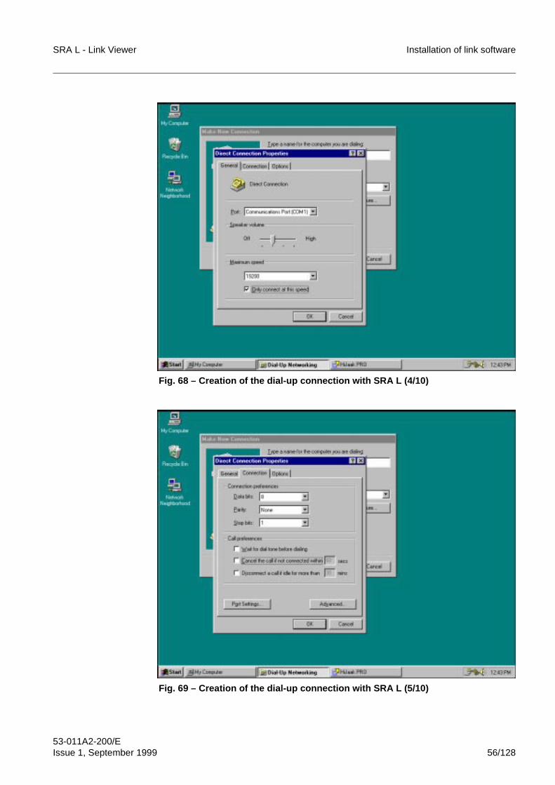
SRA L - Link Viewer Installation of link software
53-011A2-200/EIssue 1, September 1999 56/128
Fig. 68 – Creation of the dial-up connection with SRA L (4/10)
Fig. 69 – Creation of the dial-up connection with SRA L (5/10)
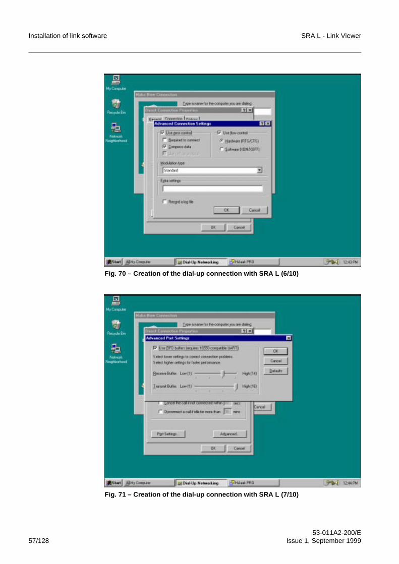
Installation of link software SRA L - Link Viewer
53-011A2-200/E57/128 Issue 1, September 1999
Fig. 70 – Creation of the dial-up connection with SRA L (6/10)
Fig. 71 – Creation of the dial-up connection with SRA L (7/10)
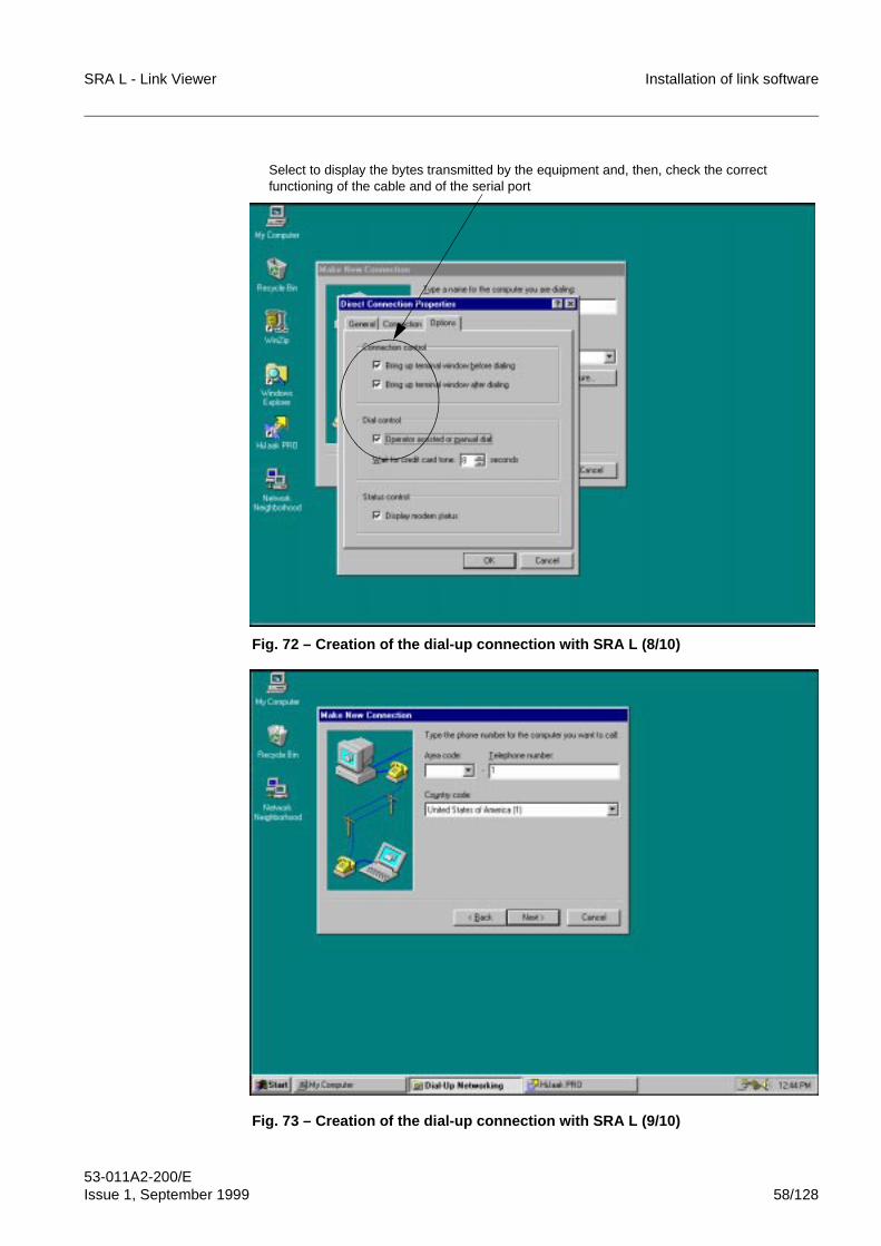
SRA L - Link Viewer Installation of link software
53-011A2-200/EIssue 1, September 1999 58/128
Fig. 72 – Creation of the dial-up connection with SRA L (8/10)
Fig. 73 – Creation of the dial-up connection with SRA L (9/10)
Select to display the bytes transmitted by the equipment and, then, check the correct functioning of the cable and of the serial port
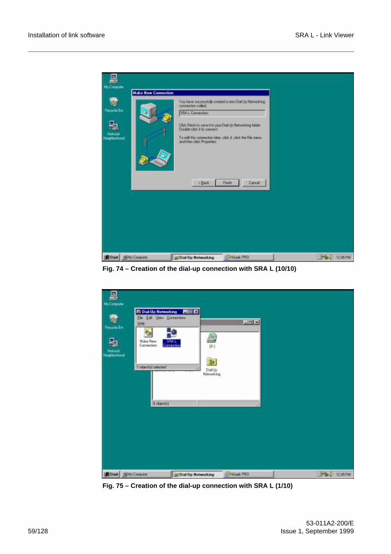
Installation of link software SRA L - Link Viewer
53-011A2-200/E59/128 Issue 1, September 1999
Fig. 74 – Creation of the dial-up connection with SRA L (10/10)
Fig. 75 – Creation of the dial-up connection with SRA L (1/10)
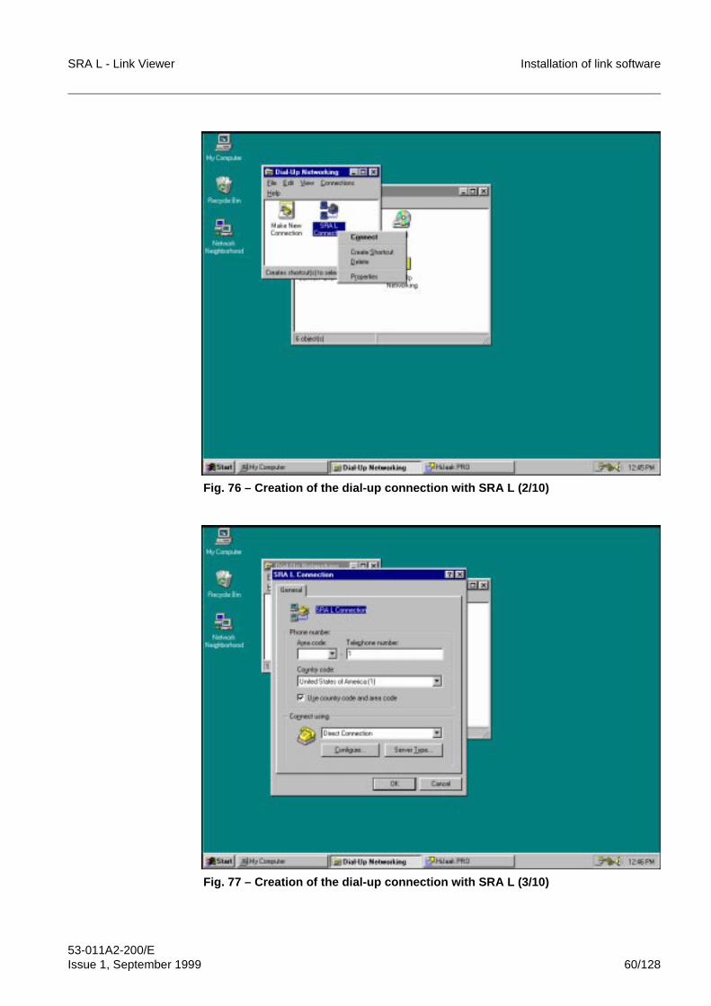
SRA L - Link Viewer Installation of link software
53-011A2-200/EIssue 1, September 1999 60/128
Fig. 76 – Creation of the dial-up connection with SRA L (2/10)
Fig. 77 – Creation of the dial-up connection with SRA L (3/10)
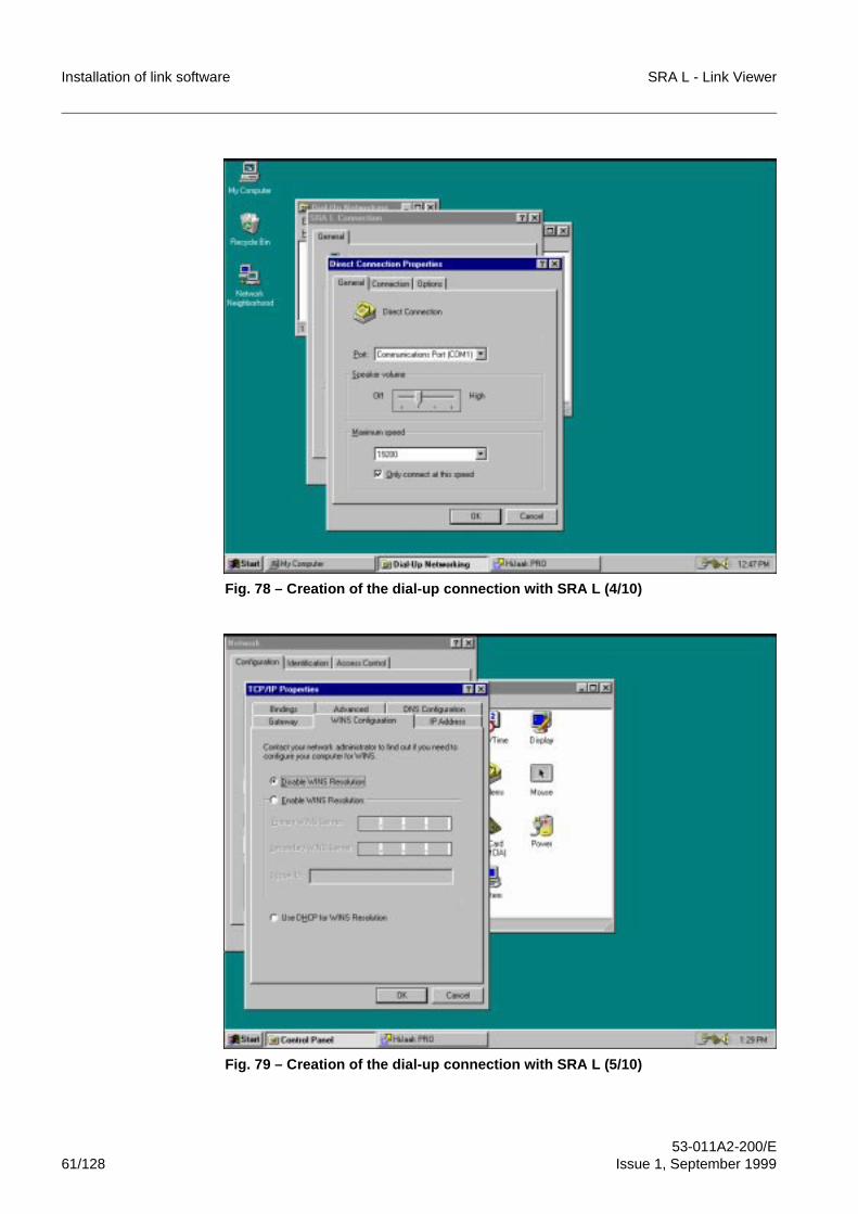
Installation of link software SRA L - Link Viewer
53-011A2-200/E61/128 Issue 1, September 1999
Fig. 78 – Creation of the dial-up connection with SRA L (4/10)
Fig. 79 – Creation of the dial-up connection with SRA L (5/10)
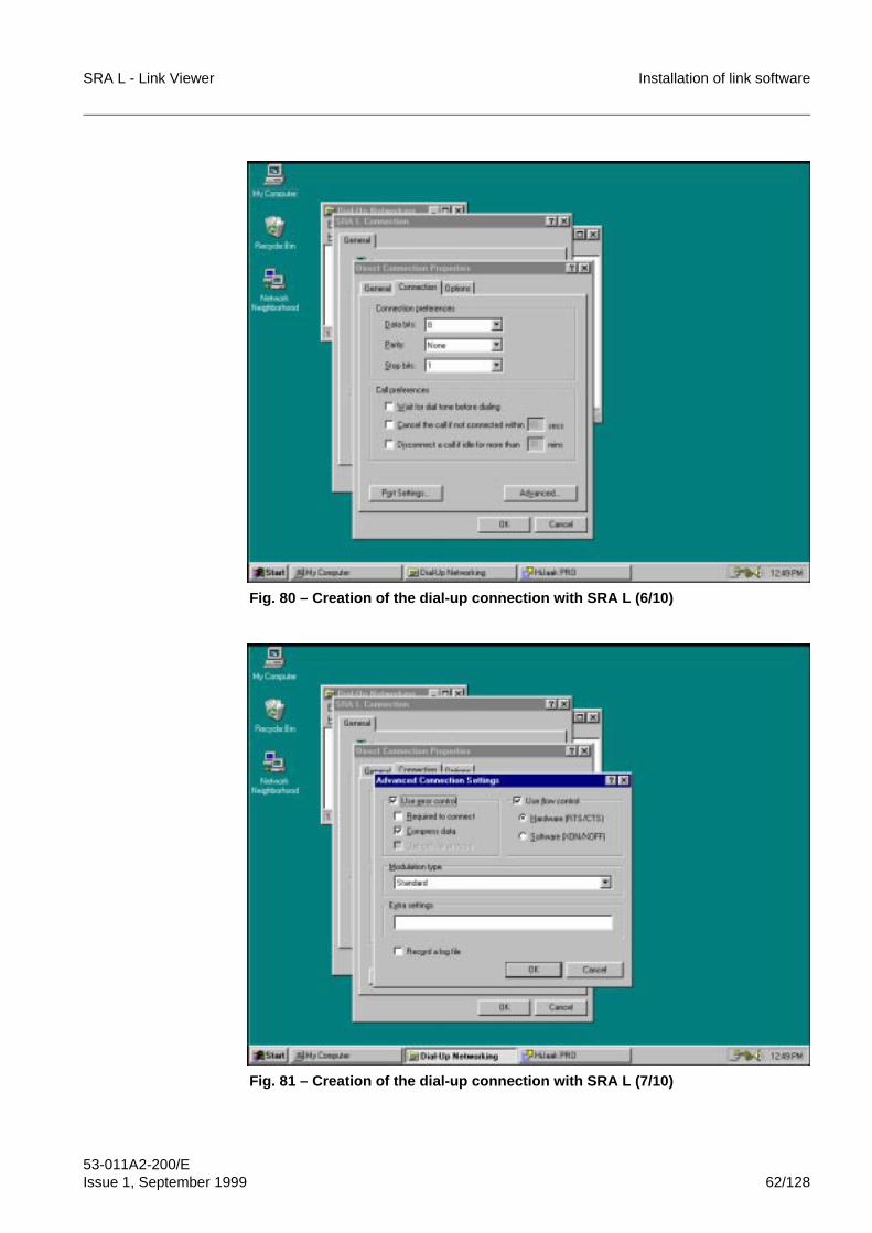
SRA L - Link Viewer Installation of link software
53-011A2-200/EIssue 1, September 1999 62/128
Fig. 80 – Creation of the dial-up connection with SRA L (6/10)
Fig. 81 – Creation of the dial-up connection with SRA L (7/10)
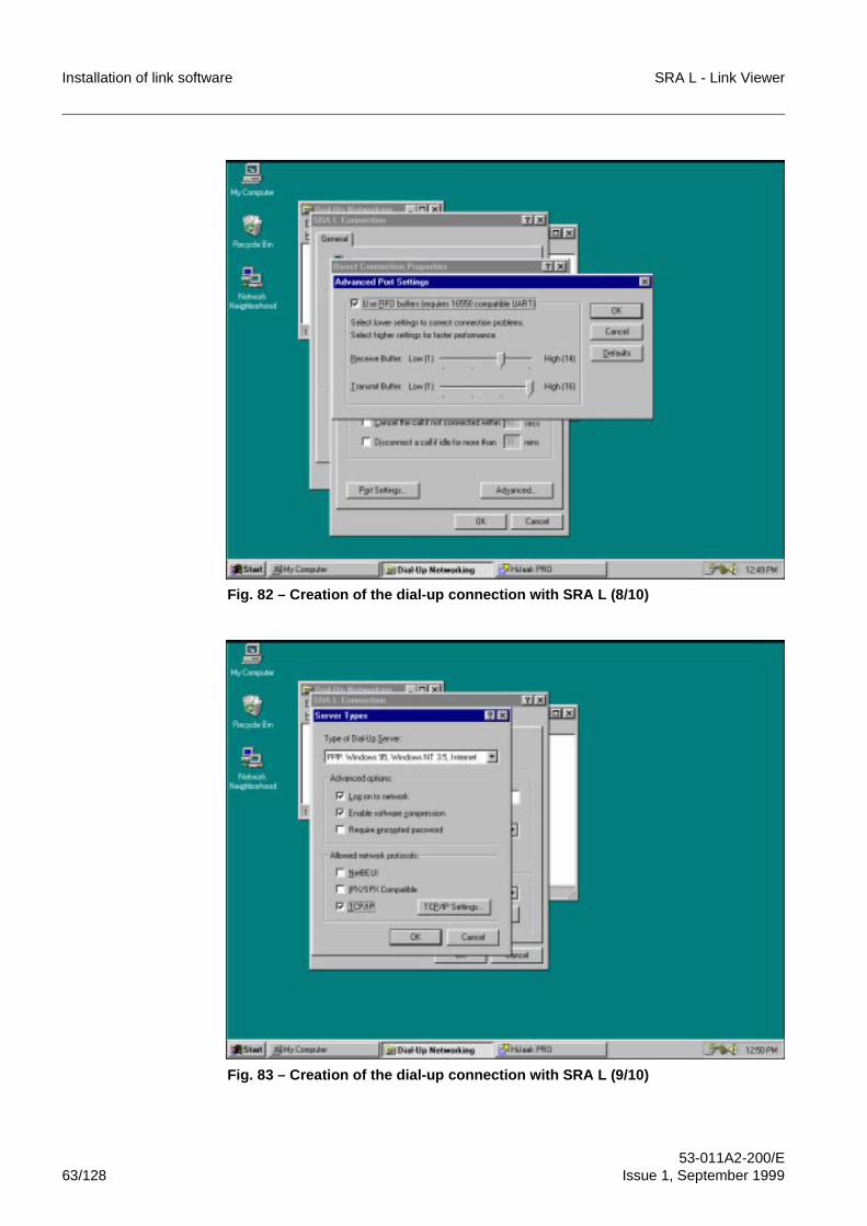
Installation of link software SRA L - Link Viewer
53-011A2-200/E63/128 Issue 1, September 1999
Fig. 82 – Creation of the dial-up connection with SRA L (8/10)
Fig. 83 – Creation of the dial-up connection with SRA L (9/10)
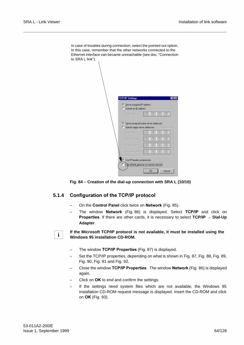
SRA L - Link Viewer Installation of link software
53-011A2-200/EIssue 1, September 1999 64/128
Fig. 84 – Creation of the dial-up connection with SRA L (10/10)
5.1.4 &RQILJXUDWLRQ�RI�WKH�7&3�,3�SURWRFRO
– On the &RQWURO�3DQHO click twice on�1HWZRUN (Fig. 85).
– The window 1HWZRUN (Fig. 86) is displayed. Select 7&3�,3 and click on3URSHUWLHV. If there are other cards, it is necessary to select TCP/IP → Dial-UpAdapter.
– The window 7&3�,3�3URSHUWLHV (Fig. 87) is displayed.
– Set the TCP/IP properties, depending on what is shown in Fig. 87, Fig. 88, Fig. 89,Fig. 90, Fig. 91 and Fig. 92.
– Close the window 7&3�,3�3URSHUWLHV . The window 1HWZRUN (Fig. 86) is displayedagain.
– Click on 2. to end and confirm the settings.
– If the settings need system files which are not available, the Windows 95installation CD-ROM request message is displayed. Insert the CD-ROM and clickon 2. (Fig. 93).
If the Microsoft TCP/IP protocol is not available, it must be installed using theWindows 95 installation CD-ROM.
In case of troubles during connection, select the pointed out option. In this case, remember that the other networks connected to the Ethernet interface can became unreachable (see doc. “Connection to SRA L link”).
i
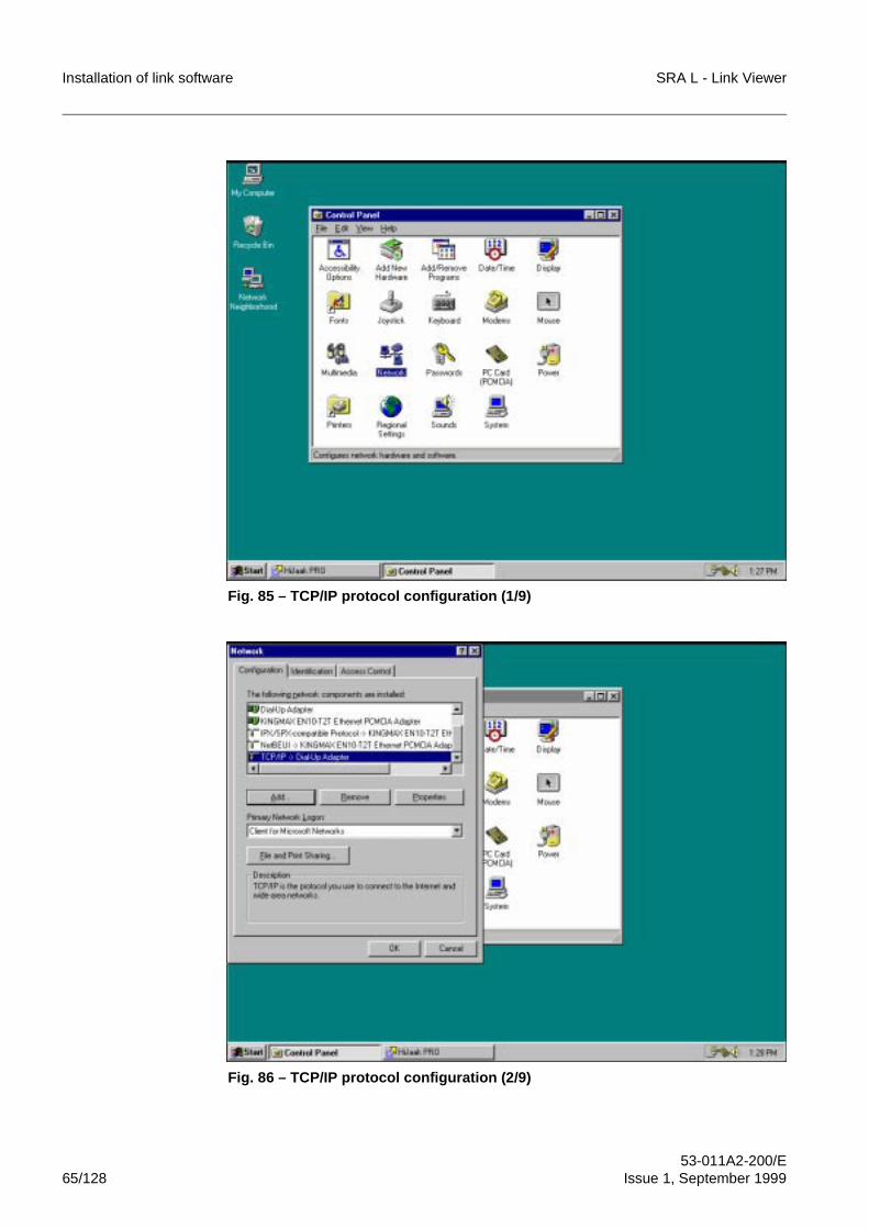
Installation of link software SRA L - Link Viewer
53-011A2-200/E65/128 Issue 1, September 1999
Fig. 85 – TCP/IP protocol configuration (1/9)
Fig. 86 – TCP/IP protocol configuration (2/9)
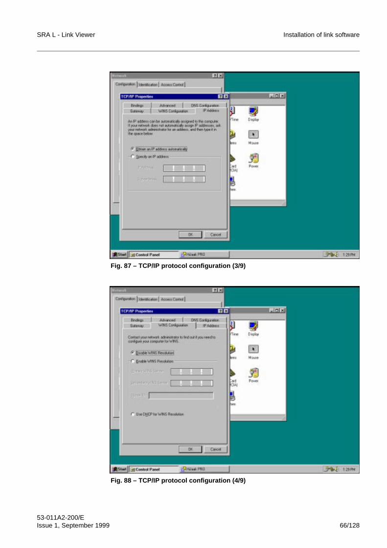
SRA L - Link Viewer Installation of link software
53-011A2-200/EIssue 1, September 1999 66/128
Fig. 87 – TCP/IP protocol configuration (3/9)
Fig. 88 – TCP/IP protocol configuration (4/9)
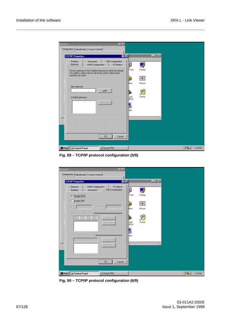
Installation of link software SRA L - Link Viewer
53-011A2-200/E67/128 Issue 1, September 1999
Fig. 89 – TCP/IP protocol configuration (5/9)
Fig. 90 – TCP/IP protocol configuration (6/9)
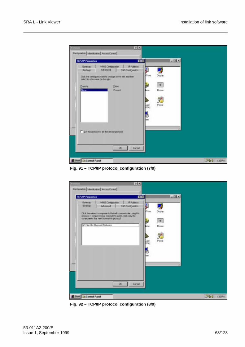
SRA L - Link Viewer Installation of link software
53-011A2-200/EIssue 1, September 1999 68/128
Fig. 91 – TCP/IP protocol configuration (7/9)
Fig. 92 – TCP/IP protocol configuration (8/9)
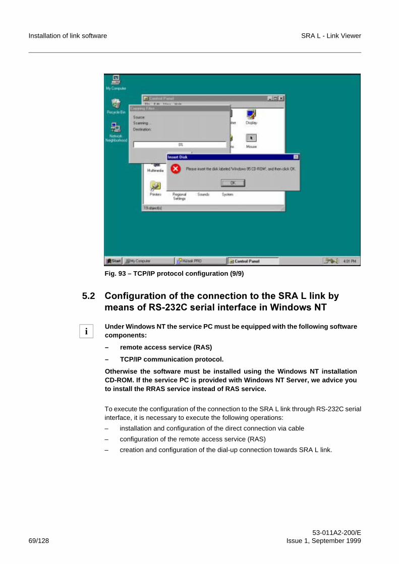
Installation of link software SRA L - Link Viewer
53-011A2-200/E69/128 Issue 1, September 1999
Fig. 93 – TCP/IP protocol configuration (9/9)
5.2 &RQILJXUDWLRQ�RI�WKH�FRQQHFWLRQ�WR�WKH�65$�/�OLQN�E\PHDQV�RI�56����&�VHULDO�LQWHUIDFH�LQ�:LQGRZV�17
To execute the configuration of the connection to the SRA L link through RS-232C serialinterface, it is necessary to execute the following operations:
– installation and configuration of the direct connection via cable
– configuration of the remote access service (RAS)
– creation and configuration of the dial-up connection towards SRA L link.
Under Windows NT the service PC must be equipped with the following softwarecomponents:
– remote access service (RAS)
– TCP/IP communication protocol.
Otherwise the software must be installed using the Windows NT installationCD-ROM. If the service PC is provided with Windows NT Server, we advice youto install the RRAS service instead of RAS service.
i
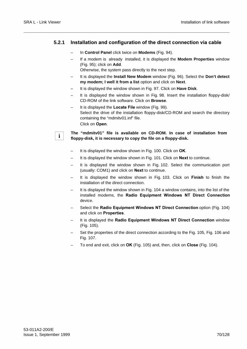
SRA L - Link Viewer Installation of link software
53-011A2-200/EIssue 1, September 1999 70/128
5.2.1 ,QVWDOODWLRQ�DQG�FRQILJXUDWLRQ�RI�WKH�GLUHFW�FRQQHFWLRQ�YLD�FDEOH
– In Control Panel click twice on Modems (Fig. 94).
– If a modem is already installed, it is displayed the Modem Properties window(Fig. 95); click on Add.Otherwise, the system pass directly to the next step.
– It is displayed the Install New Modem window (Fig. 96). Select the Don’t detectmy modem; I well it from a list option and click on Next .
– It is displayed the window shown in Fig. 97. Click on Have Disk.
– It is displayed the window shown in Fig. 98. Insert the installation floppy-disk/CD-ROM of the link software. Click on Browse.
– It is displayed the /RFDWH�)LOH window (Fig. 99).Select the drive of the installation floppy-disk/CD-ROM and search the directorycontaining the “mdmitv01.inf” file.Click on 2SHQ.
– It is displayed the window shown in Fig. 100. Click on 2..
– It is displayed the window shown in Fig. 101. Click on 1H[W to continue.
– It is displayed the window shown in Fig. 102. Select the communication port(usually: COM1) and click on 1H[W to continue.
– It is displayed the window shown in Fig. 103. Click on )LQLVK to finish theinstallation of the direct connection.
– It is displayed the window shown in Fig. 104 a window contains, into the list of theinstalled modems, the 5DGLR� (TXLSPHQW� :LQGRZV� 17� 'LUHFW� &RQQHFWLRQdevice.
– Select the 5DGLR�(TXLSPHQW�:LQGRZV�17�'LUHFW�&RQQHFWLRQ option (Fig. 104)and click on 3URSHUWLHV.
– It is displayed the 5DGLR�(TXLSPHQW�:LQGRZV�17�'LUHFW�&RQQHFWLRQ window(Fig. 105).
– Set the properties of the direct connection according to the Fig. 105, Fig. 106 andFig. 107.
– To end and exit, click on 2. (Fig. 105) and, then, click on &ORVH (Fig. 104).
The “mdmitv01” file is available on CD-ROM. In case of installation fromfloppy-disk, it is necessary to copy the file on a floppy-disk.i
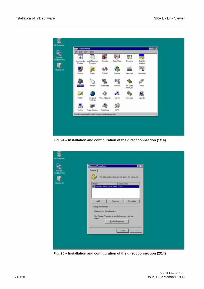
Installation of link software SRA L - Link Viewer
53-011A2-200/E71/128 Issue 1, September 1999
Fig. 94 – Installation and configuration of the direct connection (1/14)
Fig. 95 – Installation and configuration of the direct connection (2/14)
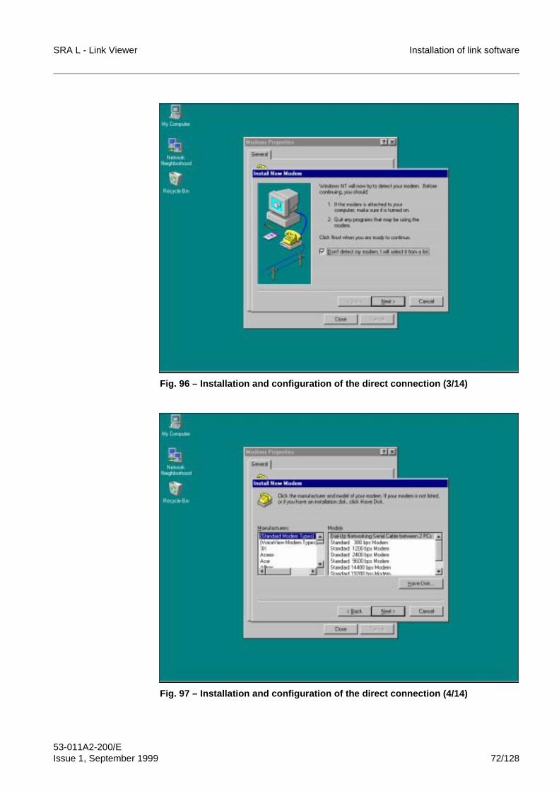
SRA L - Link Viewer Installation of link software
53-011A2-200/EIssue 1, September 1999 72/128
Fig. 96 – Installation and configuration of the direct connection (3/14)
Fig. 97 – Installation and configuration of the direct connection (4/14)
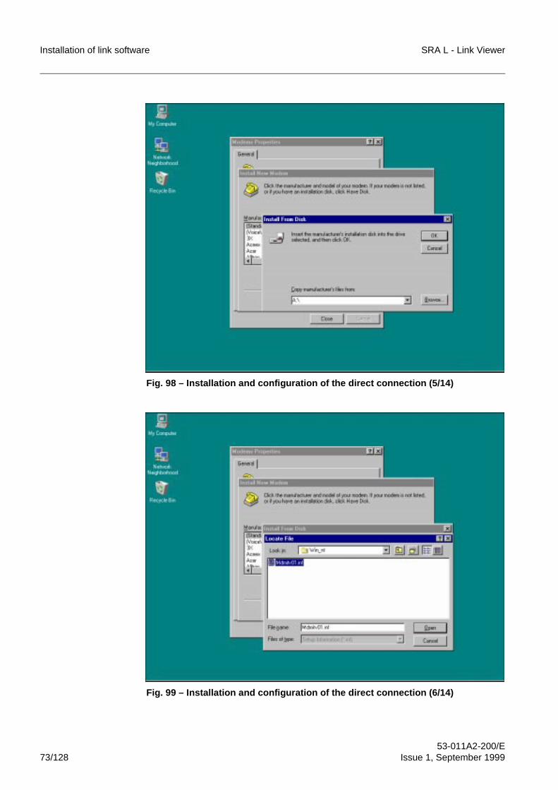
Installation of link software SRA L - Link Viewer
53-011A2-200/E73/128 Issue 1, September 1999
Fig. 98 – Installation and configuration of the direct connection (5/14)
Fig. 99 – Installation and configuration of the direct connection (6/14)
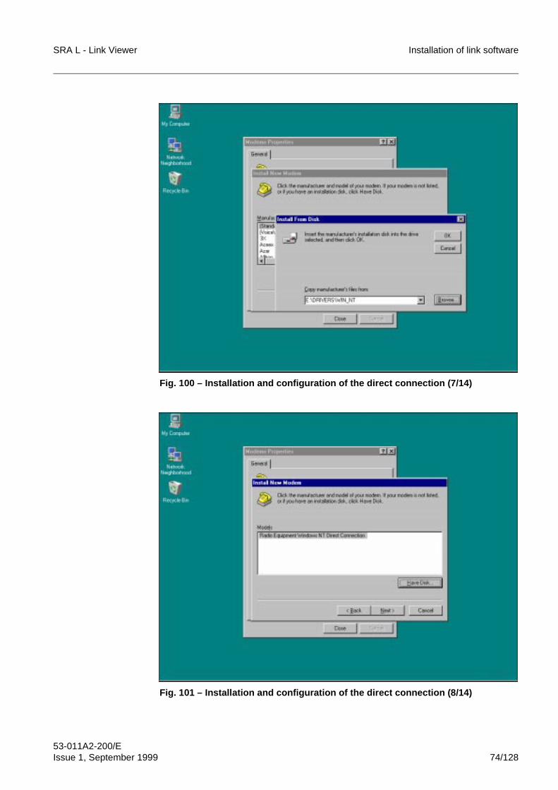
SRA L - Link Viewer Installation of link software
53-011A2-200/EIssue 1, September 1999 74/128
Fig. 100 – Installation and configuration of the direct connection (7/14)
Fig. 101 – Installation and configuration of the direct connection (8/14)
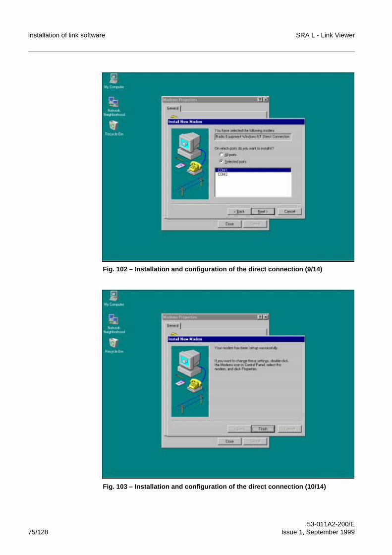
Installation of link software SRA L - Link Viewer
53-011A2-200/E75/128 Issue 1, September 1999
Fig. 102 – Installation and configuration of the direct connection (9/14)
Fig. 103 – Installation and configuration of the direct connection (10/14)
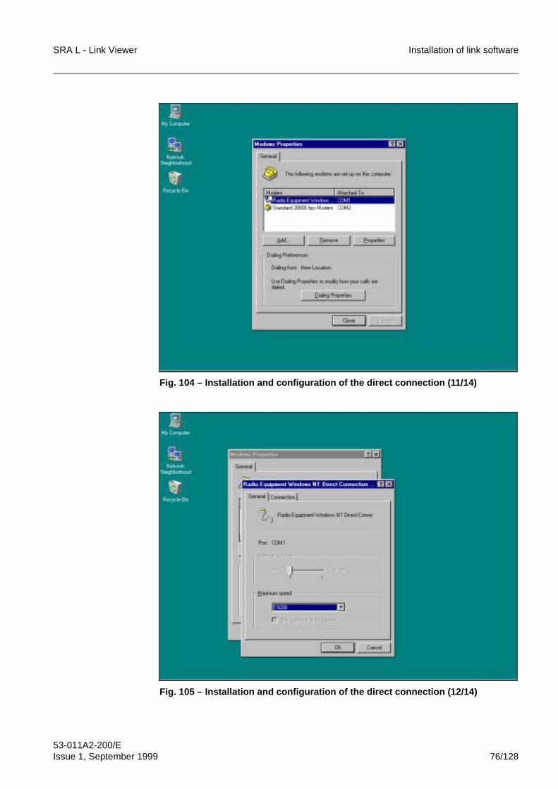
SRA L - Link Viewer Installation of link software
53-011A2-200/EIssue 1, September 1999 76/128
Fig. 104 – Installation and configuration of the direct connection (11/14)
Fig. 105 – Installation and configuration of the direct connection (12/14)
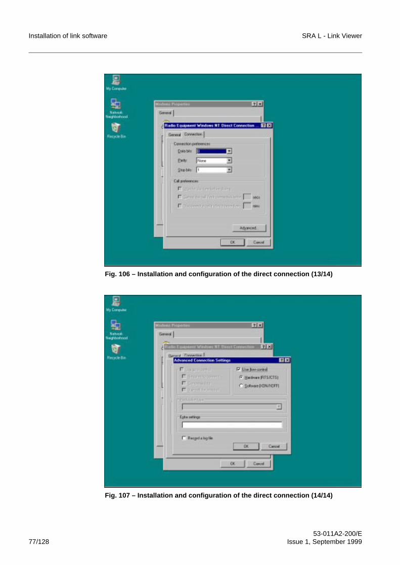
Installation of link software SRA L - Link Viewer
53-011A2-200/E77/128 Issue 1, September 1999
Fig. 106 – Installation and configuration of the direct connection (13/14)
Fig. 107 – Installation and configuration of the direct connection (14/14)
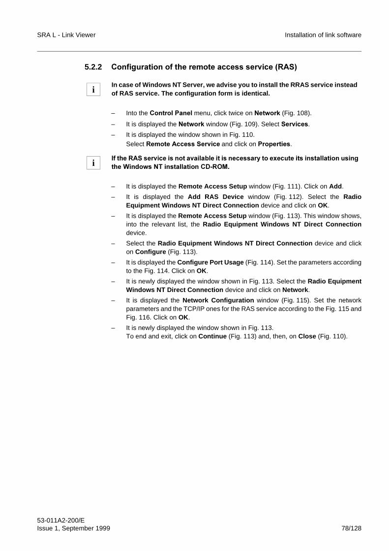
SRA L - Link Viewer Installation of link software
53-011A2-200/EIssue 1, September 1999 78/128
5.2.2 &RQILJXUDWLRQ�RI�WKH�UHPRWH�DFFHVV�VHUYLFH��5$6�
– Into the &RQWURO�3DQHO�menu, click twice on 1HWZRUN (Fig. 108).
– It is displayed the 1HWZRUN window (Fig. 109). Select 6HUYLFHV.
– It is displayed the window shown in Fig. 110.Select 5HPRWH�$FFHVV�6HUYLFH and click on 3URSHUWLHV.
– It is displayed the Remote Access Setup window (Fig. 111). Click on Add.
– It is displayed the Add RAS Device window (Fig. 112). Select the RadioEquipment Windows NT Direct Connection device and click on OK.
– It is displayed the Remote Access Setup window (Fig. 113). This window shows,into the relevant list, the Radio Equipment Windows NT Direct Connectiondevice.
– Select the Radio Equipment Windows NT Direct Connection device and clickon Configure (Fig. 113).
– It is displayed the Configure Port Usage (Fig. 114). Set the parameters accordingto the Fig. 114. Click on OK.
– It is newly displayed the window shown in Fig. 113. Select the Radio EquipmentWindows NT Direct Connection device and click on Network.
– It is displayed the Network Configuration window (Fig. 115). Set the networkparameters and the TCP/IP ones for the RAS service according to the Fig. 115 andFig. 116. Click on OK.
– It is newly displayed the window shown in Fig. 113.To end and exit, click on Continue (Fig. 113) and, then, on Close (Fig. 110).
In case of Windows NT Server, we advise you to install the RRAS service insteadof RAS service. The configuration form is identical.
,I�WKH�5$6�VHUYLFH�LV�QRW�DYDLODEOH�LW�LV�QHFHVVDU\�WR�H[HFXWH�LWV�LQVWDOODWLRQ�XVLQJWKH�:LQGRZV�17�LQVWDOODWLRQ�&'�520�
i
i
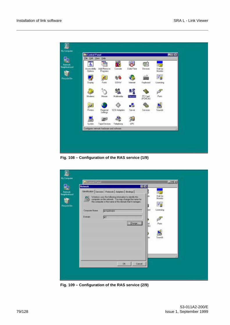
Installation of link software SRA L - Link Viewer
53-011A2-200/E79/128 Issue 1, September 1999
Fig. 108 – Configuration of the RAS service (1/9)
Fig. 109 – Configuration of the RAS service (2/9)
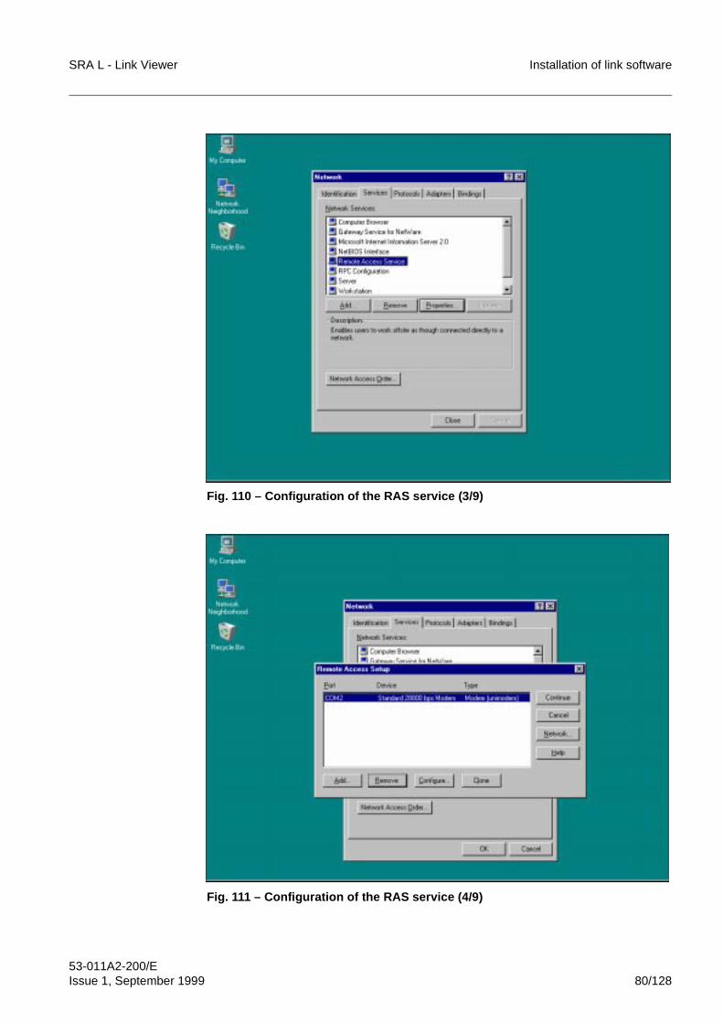
SRA L - Link Viewer Installation of link software
53-011A2-200/EIssue 1, September 1999 80/128
Fig. 110 – Configuration of the RAS service (3/9)
Fig. 111 – Configuration of the RAS service (4/9)
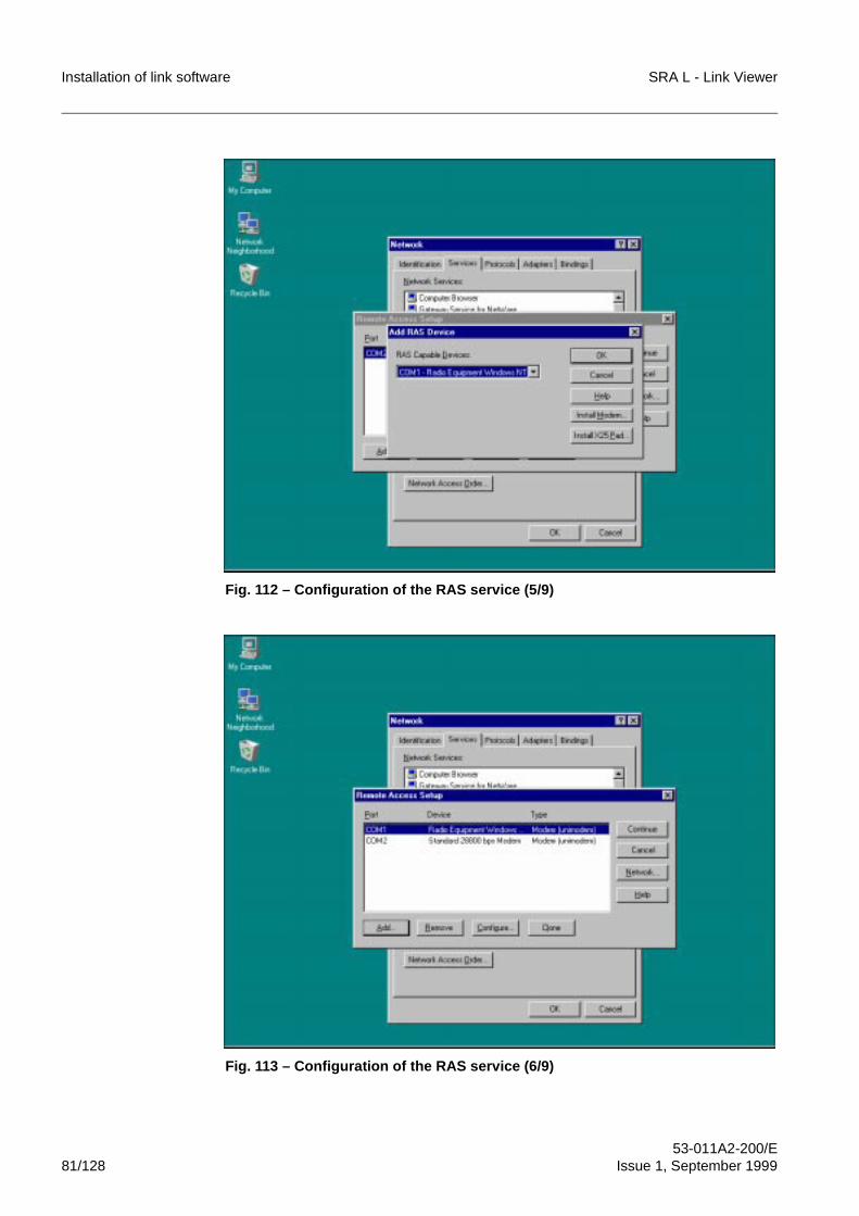
Installation of link software SRA L - Link Viewer
53-011A2-200/E81/128 Issue 1, September 1999
Fig. 112 – Configuration of the RAS service (5/9)
Fig. 113 – Configuration of the RAS service (6/9)
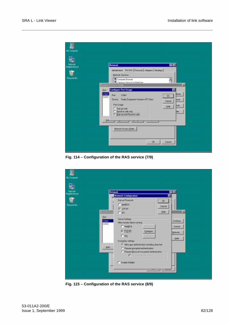
SRA L - Link Viewer Installation of link software
53-011A2-200/EIssue 1, September 1999 82/128
Fig. 114 – Configuration of the RAS service (7/9)
Fig. 115 – Configuration of the RAS service (8/9)
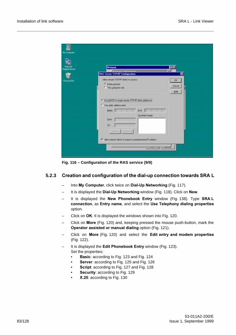
Installation of link software SRA L - Link Viewer
53-011A2-200/E83/128 Issue 1, September 1999
Fig. 116 – Configuration of the RAS service (9/9)
5.2.3 &UHDWLRQ�DQG�FRQILJXUDWLRQ�RI�WKH�GLDO�XS�FRQQHFWLRQ�WRZDUGV�65$ /
– Into 0\�&RPSXWHU, click twice on 'LDO�8S�1HWZRUNLQJ (Fig. 117).
– It is displayed the 'LDO�8S�1HWZRUNLQJ window (Fig. 118). Click on 1HZ.
– It is displayed the 1HZ� 3KRQHERRN� (QWU\ window (Fig. 138). Type 65$ /FRQQHFWLRQ, as (QWU\�QDPH, and select the 8VH�7HOHSKRQ\�GLDOLQJ�SURSHUWLHVoption.
– Click on 2.. It is displayed the windows shown into Fig. 120.
– Click on 0RUH (Fig. 120) and, keeping pressed the mouse push-button, mark the2SHUDWRU�DVVLVWHG�RU�PDQXDO�GLDOLQJ option (Fig. 121).
– Click on 0RUH (Fig. 120) and select the (GLW�HQWU\�DQG�PRGHP�SURSHUWLHV(Fig. 122).
– It is displayed the (GLW�3KRQHERRN�(QWU\ window (Fig. 123).Set the properties:• %DVLF: according to Fig. 123 and Fig. 124• 6HUYHU: according to Fig. 125 and Fig. 126• 6FULSW: according to Fig. 127 and Fig. 128• 6HFXULW\: according to Fig. 129 • ;���: according to Fig. 130
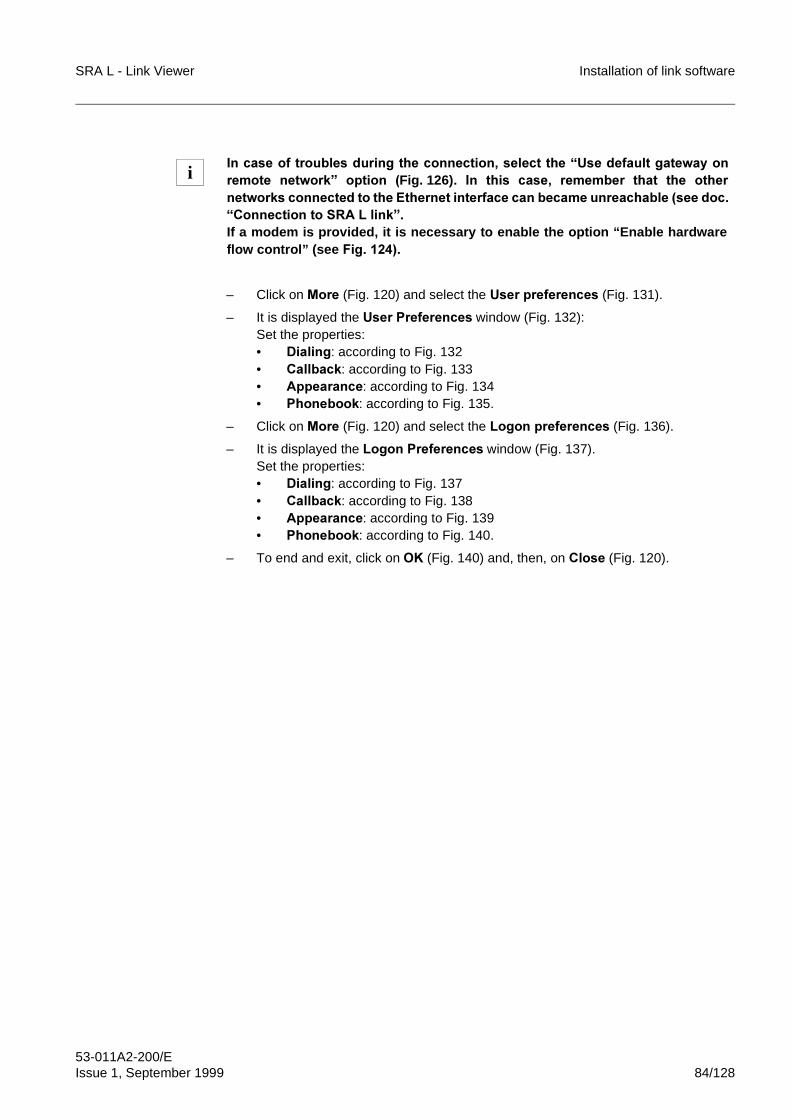
SRA L - Link Viewer Installation of link software
53-011A2-200/EIssue 1, September 1999 84/128
– Click on 0RUH (Fig. 120) and select the 8VHU SUHIHUHQFHV (Fig. 131).
– It is displayed the 8VHU�3UHIHUHQFHV�window (Fig. 132):Set the properties:• 'LDOLQJ: according to Fig. 132 • &DOOEDFN: according to Fig. 133• $SSHDUDQFH: according to Fig. 134 • 3KRQHERRN: according to Fig. 135.
– Click on 0RUH (Fig. 120) and select the /RJRQ�SUHIHUHQFHV�(Fig. 136).
– It is displayed the /RJRQ�3UHIHUHQFHV�window (Fig. 137).Set the properties:• 'LDOLQJ: according to Fig. 137 • &DOOEDFN: according to Fig. 138• $SSHDUDQFH: according to Fig. 139 • 3KRQHERRN: according to Fig. 140.
– To end and exit, click on 2. (Fig. 140) and, then, on &ORVH (Fig. 120).
,Q�FDVH�RI�WURXEOHV�GXULQJ�WKH�FRQQHFWLRQ��VHOHFW�WKH�³8VH�GHIDXOW�JDWHZD\�RQUHPRWH� QHWZRUN´� RSWLRQ� �Fig. 126)�� ,Q� WKLV� FDVH�� UHPHPEHU� WKDW� WKH� RWKHUQHWZRUNV�FRQQHFWHG�WR�WKH�(WKHUQHW�LQWHUIDFH�FDQ�EHFDPH�XQUHDFKDEOH��VHH�GRF�³&RQQHFWLRQ�WR�65$ /�OLQN´�If a modem is provided, it is necessary to enable the option “Enable hardwareflow control” (see )LJ� �����
i
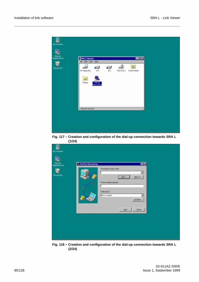
Installation of link software SRA L - Link Viewer
53-011A2-200/E85/128 Issue 1, September 1999
.
Fig. 117 – Creation and configuration of the dial-up connection towards SRA L (1/24)
Fig. 118 – Creation and configuration of the dial-up connection towards SRA L (2/24)
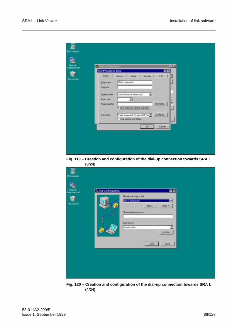
SRA L - Link Viewer Installation of link software
53-011A2-200/EIssue 1, September 1999 86/128
Fig. 119 – Creation and configuration of the dial-up connection towards SRA L (3/24)
Fig. 120 – Creation and configuration of the dial-up connection towards SRA L (4/24)
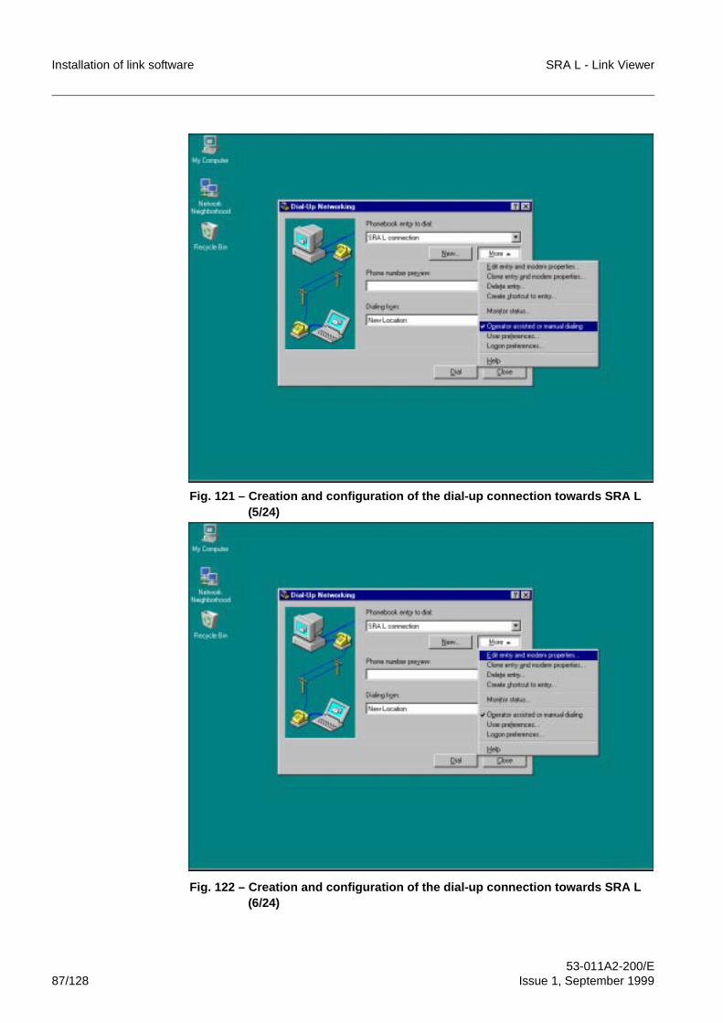
Installation of link software SRA L - Link Viewer
53-011A2-200/E87/128 Issue 1, September 1999
Fig. 121 – Creation and configuration of the dial-up connection towards SRA L (5/24)
Fig. 122 – Creation and configuration of the dial-up connection towards SRA L (6/24)
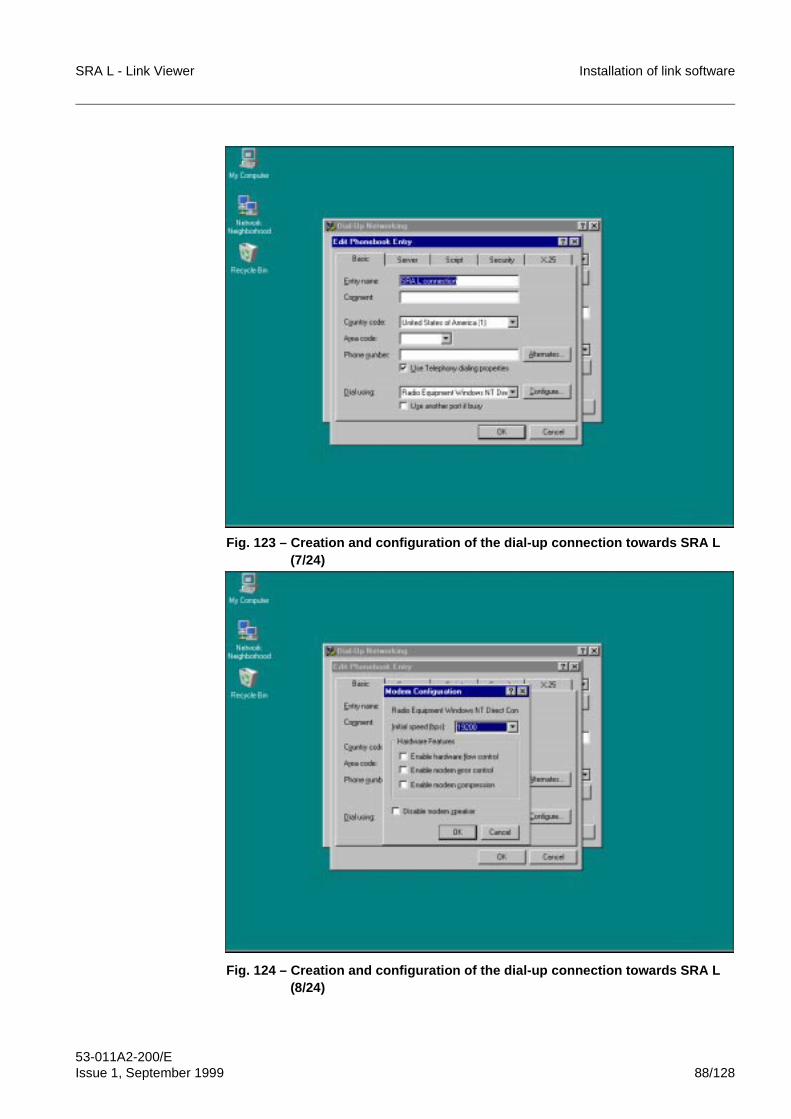
SRA L - Link Viewer Installation of link software
53-011A2-200/EIssue 1, September 1999 88/128
Fig. 123 – Creation and configuration of the dial-up connection towards SRA L (7/24)
Fig. 124 – Creation and configuration of the dial-up connection towards SRA L (8/24)
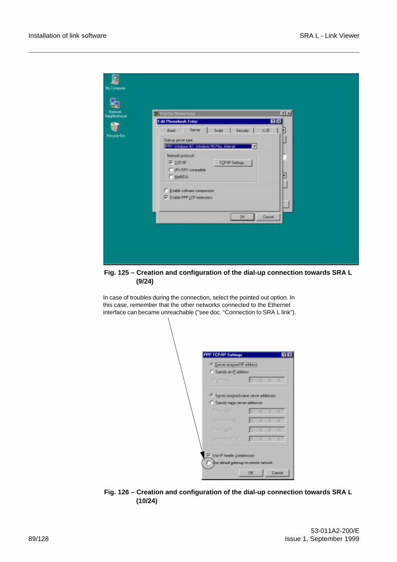
Installation of link software SRA L - Link Viewer
53-011A2-200/E89/128 Issue 1, September 1999
Fig. 125 – Creation and configuration of the dial-up connection towards SRA L (9/24)
Fig. 126 – Creation and configuration of the dial-up connection towards SRA L(10/24)
In case of troubles during the connection, select the pointed out option. In this case, remember that the other networks connected to the Ethernet interface can became unreachable (“see doc. “Connection to SRA L link”).
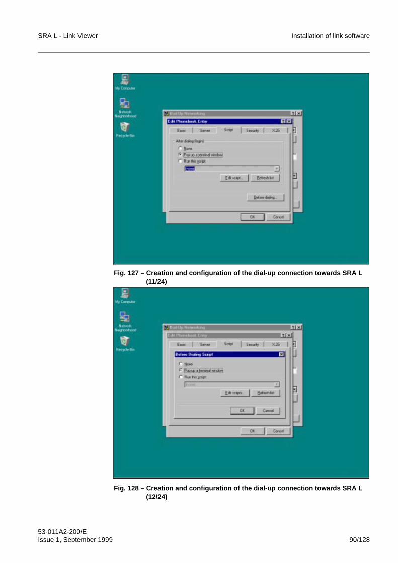
SRA L - Link Viewer Installation of link software
53-011A2-200/EIssue 1, September 1999 90/128
Fig. 127 – Creation and configuration of the dial-up connection towards SRA L(11/24)
Fig. 128 – Creation and configuration of the dial-up connection towards SRA L(12/24)
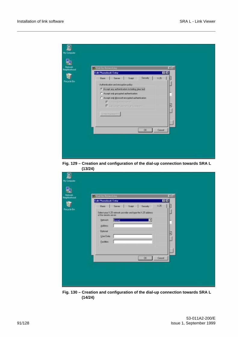
Installation of link software SRA L - Link Viewer
53-011A2-200/E91/128 Issue 1, September 1999
Fig. 129 – Creation and configuration of the dial-up connection towards SRA L(13/24)
Fig. 130 – Creation and configuration of the dial-up connection towards SRA L(14/24)
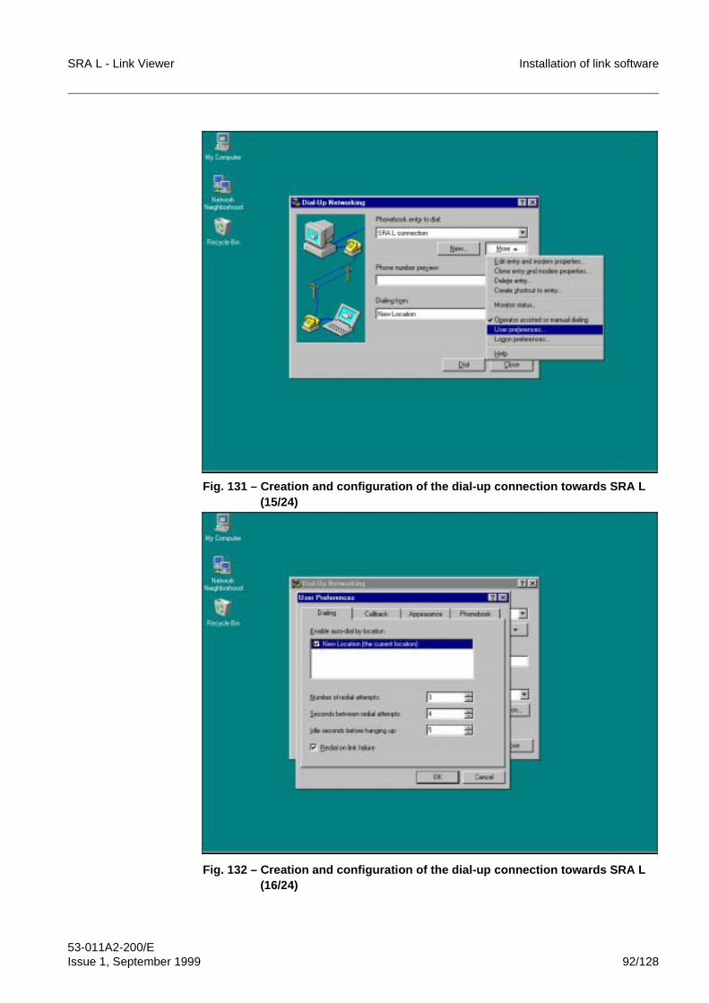
SRA L - Link Viewer Installation of link software
53-011A2-200/EIssue 1, September 1999 92/128
Fig. 131 – Creation and configuration of the dial-up connection towards SRA L(15/24)
Fig. 132 – Creation and configuration of the dial-up connection towards SRA L(16/24)
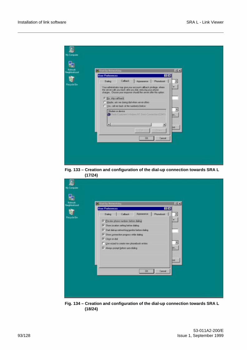
Installation of link software SRA L - Link Viewer
53-011A2-200/E93/128 Issue 1, September 1999
Fig. 133 – Creation and configuration of the dial-up connection towards SRA L(17/24)
Fig. 134 – Creation and configuration of the dial-up connection towards SRA L(18/24)
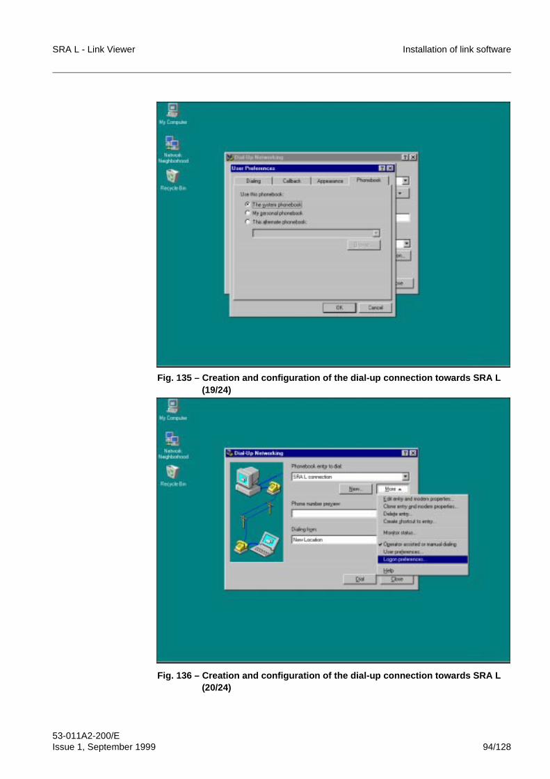
SRA L - Link Viewer Installation of link software
53-011A2-200/EIssue 1, September 1999 94/128
Fig. 135 – Creation and configuration of the dial-up connection towards SRA L(19/24)
Fig. 136 – Creation and configuration of the dial-up connection towards SRA L(20/24)
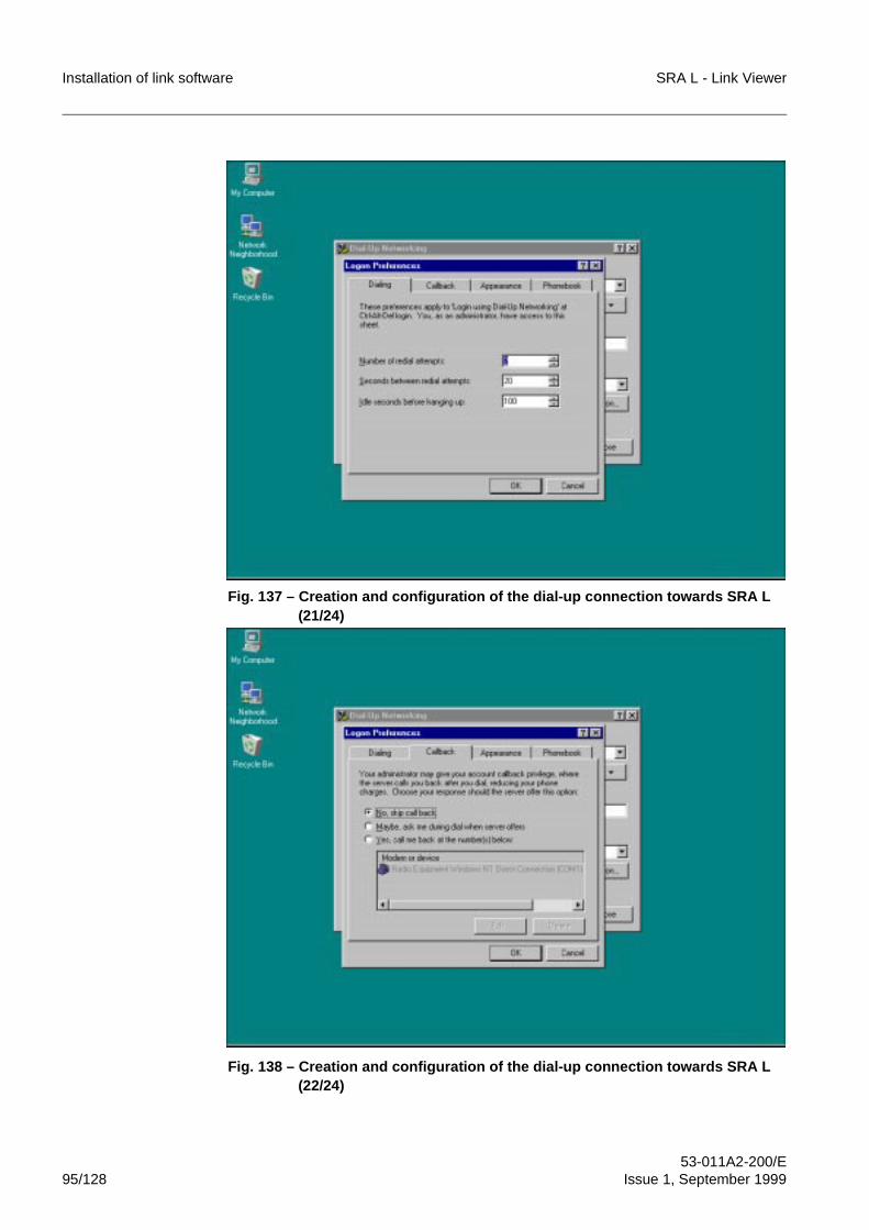
Installation of link software SRA L - Link Viewer
53-011A2-200/E95/128 Issue 1, September 1999
Fig. 137 – Creation and configuration of the dial-up connection towards SRA L(21/24)
Fig. 138 – Creation and configuration of the dial-up connection towards SRA L(22/24)
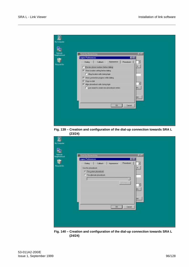
SRA L - Link Viewer Installation of link software
53-011A2-200/EIssue 1, September 1999 96/128
Fig. 139 – Creation and configuration of the dial-up connection towards SRA L(23/24)
Fig. 140 – Creation and configuration of the dial-up connection towards SRA L(24/24)
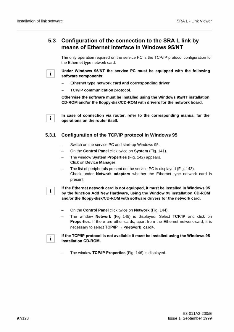
Installation of link software SRA L - Link Viewer
53-011A2-200/E97/128 Issue 1, September 1999
5.3 &RQILJXUDWLRQ�RI�WKH�FRQQHFWLRQ�WR�WKH�65$�/�OLQN�E\PHDQV�RI�(WKHUQHW�LQWHUIDFH�LQ�:LQGRZV����17
The only operation required on the service PC is the TCP/IP protocol configuration forthe Ethernet type network card.
5.3.1 Configuration of the TCP/IP protocol in Windows 95
– Switch on the service PC and start-up Windows 95.
– On the Control Panel click twice on System (Fig. 141).
– The window System Properties (Fig. 142) appears.Click on Device Manager.
– The list of peripherals present on the service PC is displayed (Fig. 143).Check under 1HWZRUN� DGDSWHUV� whether� the Ethernet type network card ispresent.
– On the Control Panel click twice on Network (Fig. 144).
– The window 1HWZRUN (Fig. 145) is displayed. Select 7&3�,3 and click on3URSHUWLHV. If there are other cards, apart from the Ethernet network card, it is
necessary to select�7&3�,3�→ �QHWZRUNBFDUG!.
– The window 7&3�,3�3URSHUWLHV (Fig. 146) is displayed.
8QGHU� :LQGRZV� ���17� WKH� VHUYLFH� 3&� PXVW� EH� HTXLSSHG� ZLWK� WKH� IROORZLQJVRIWZDUH�FRPSRQHQWV�
– Ethernet type network card and corresponding driver
– TCP/IP communication protocol.
Otherwise the software must be installed using the Windows 95/NT installationCD-ROM and/or the floppy-disk/CD-ROM with drivers for the network board.
In case of connection via router, refer to the corresponding manual for theoperations on the router itself.
,I�WKH�(WKHUQHW�QHWZRUN�FDUG�LV�QRW�HTXLSSHG��LW�PXVW�EH�LQVWDOOHG�LQ�:LQGRZV���E\�WKH�IXQFWLRQ�$GG�1HZ�+DUGZDUH��XVLQJ�WKH�:LQGRZ����LQVWDOODWLRQ�&'�520DQG�RU�WKH�IORSS\�GLVN�&'�520�ZLWK�VRIWZDUH�GULYHUV�IRU�WKH�QHWZRUN�FDUG�
,I�WKH�7&3�,3�SURWRFRO�LV�QRW�DYDLODEOH�LW�PXVW�EH�LQVWDOOHG�XVLQJ�WKH�:LQGRZV���LQVWDOODWLRQ�&'�520�
i
i
i
i
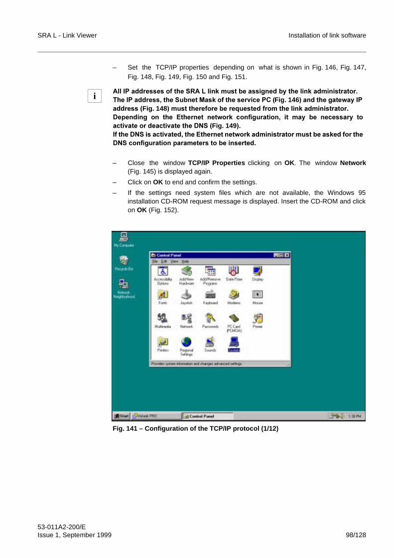
SRA L - Link Viewer Installation of link software
53-011A2-200/EIssue 1, September 1999 98/128
– Set the TCP/IP properties depending on what is shown in Fig. 146, Fig. 147,Fig. 148, Fig. 149, Fig. 150 and Fig. 151.
– Close the window TCP/IP Properties clicking on OK. The window Network(Fig. 145) is displayed again.
– Click on OK to end and confirm the settings.
– If the settings need system files which are not available, the Windows 95installation CD-ROM request message is displayed. Insert the CD-ROM and clickon OK (Fig. 152).
Fig. 141 – Configuration of the TCP/IP protocol (1/12)
$OO�,3�DGGUHVVHV�RI�WKH�65$�/�OLQN�PXVW�EH�DVVLJQHG�E\�WKH�OLQN�DGPLQLVWUDWRU�7KH�,3�DGGUHVV��WKH�6XEQHW�0DVN�RI�WKH�VHUYLFH�3&��Fig. 146 ��DQG�WKH�JDWHZD\�,3DGGUHVV��Fig. 148 ��PXVW�WKHUHIRUH�EH�UHTXHVWHG�IURP�WKH�OLQN�DGPLQLVWUDWRU�'HSHQGLQJ� RQ� WKH� (WKHUQHW� QHWZRUN� FRQILJXUDWLRQ�� LW� PD\� EH� QHFHVVDU\� WRDFWLYDWH�RU�GHDFWLYDWH�WKH�'16��Fig. 149 ��,I�WKH�'16�LV�DFWLYDWHG��WKH�(WKHUQHW�QHWZRUN�DGPLQLVWUDWRU�PXVW�EH�DVNHG�IRU�WKH'16�FRQILJXUDWLRQ�SDUDPHWHUV�WR�EH�LQVHUWHG�
i
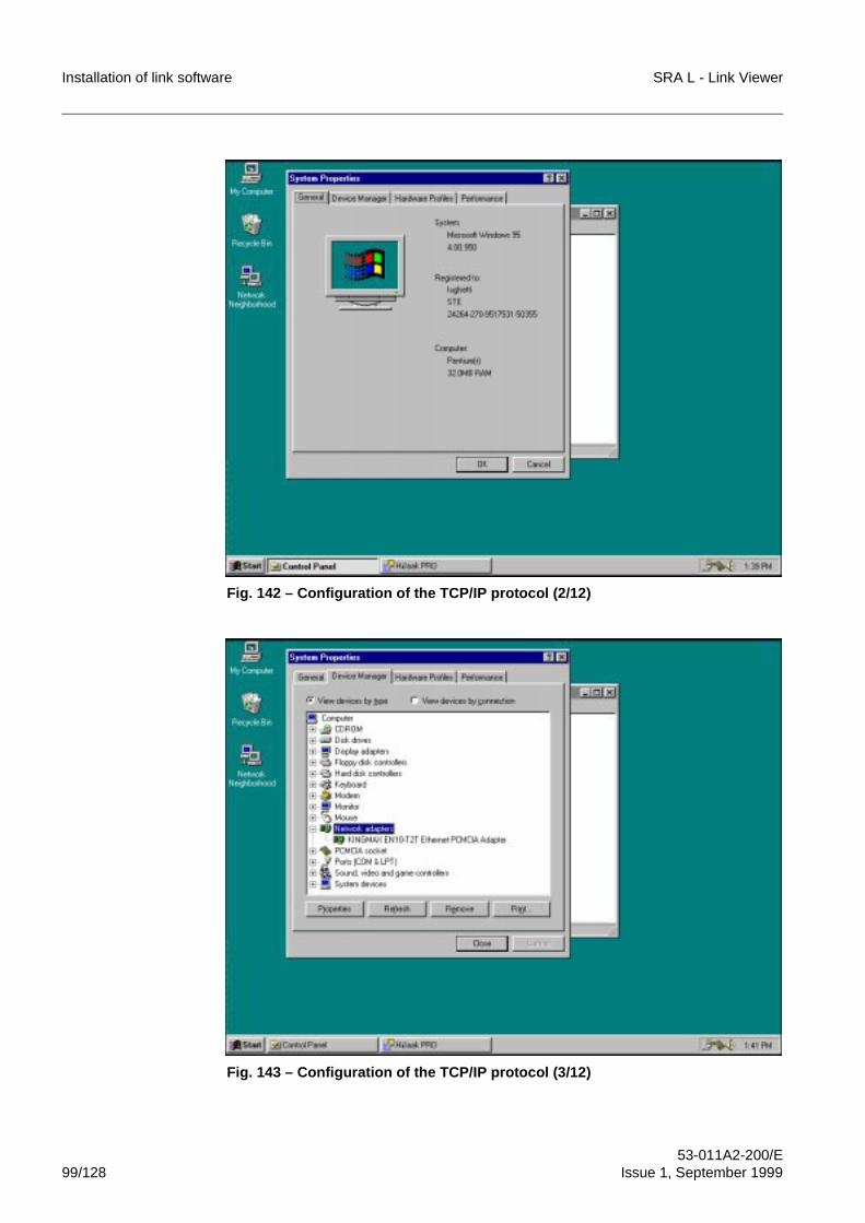
Installation of link software SRA L - Link Viewer
53-011A2-200/E99/128 Issue 1, September 1999
Fig. 142 – Configuration of the TCP/IP protocol (2/12)
Fig. 143 – Configuration of the TCP/IP protocol (3/12)
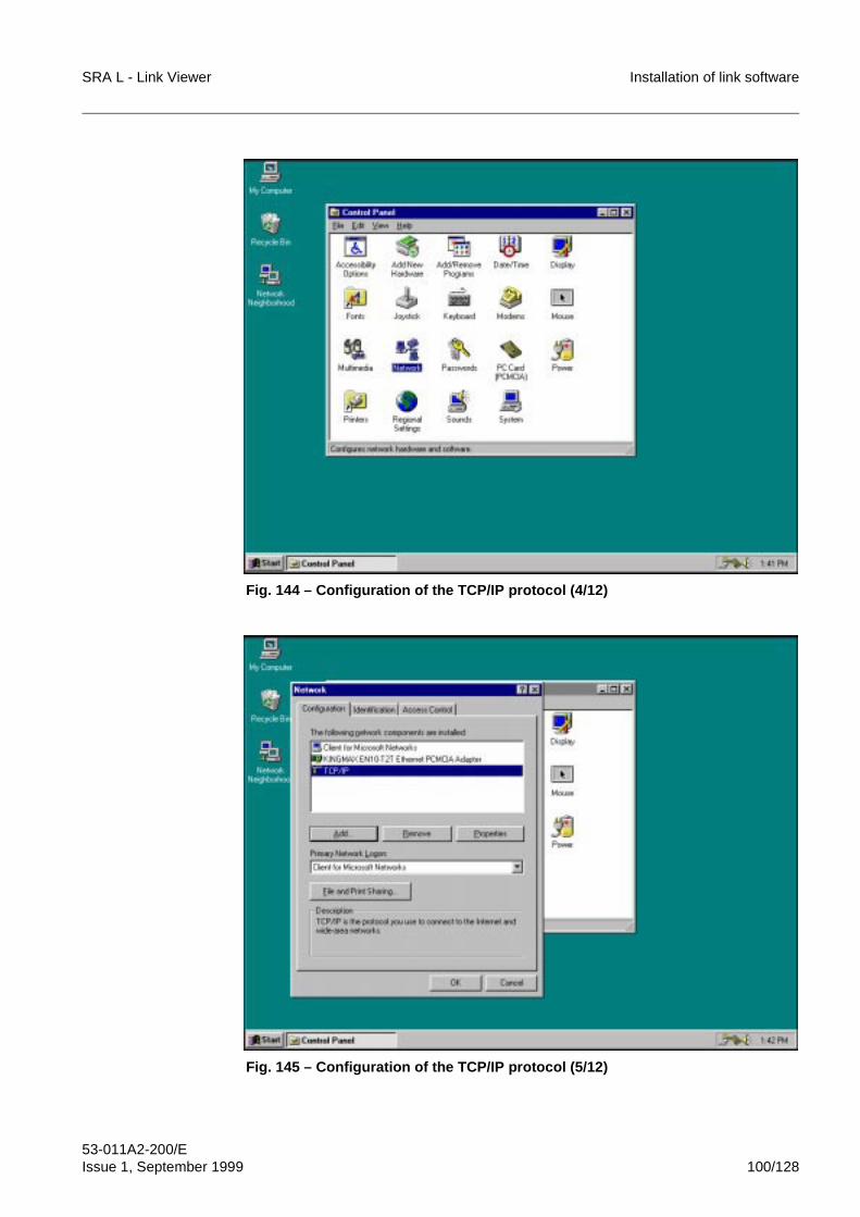
SRA L - Link Viewer Installation of link software
53-011A2-200/EIssue 1, September 1999 100/128
Fig. 144 – Configuration of the TCP/IP protocol (4/12)
Fig. 145 – Configuration of the TCP/IP protocol (5/12)
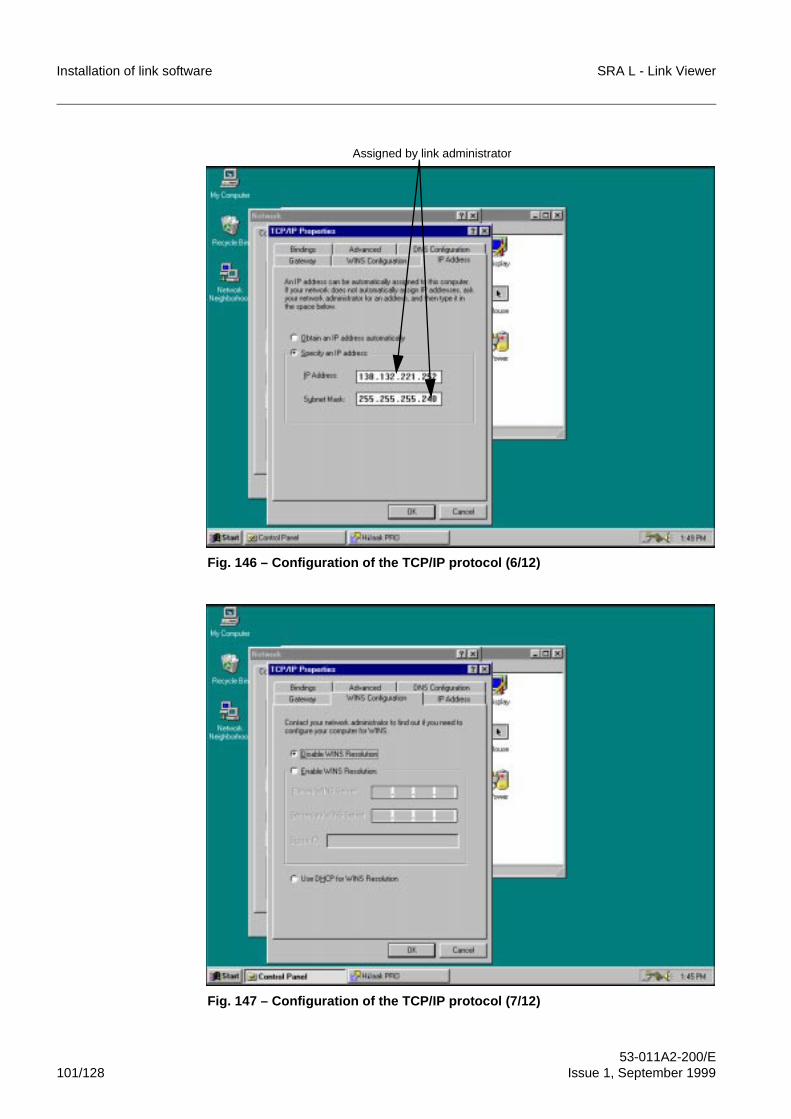
Installation of link software SRA L - Link Viewer
53-011A2-200/E101/128 Issue 1, September 1999
Fig. 146 – Configuration of the TCP/IP protocol (6/12)
Fig. 147 – Configuration of the TCP/IP protocol (7/12)
Assigned by link administrator
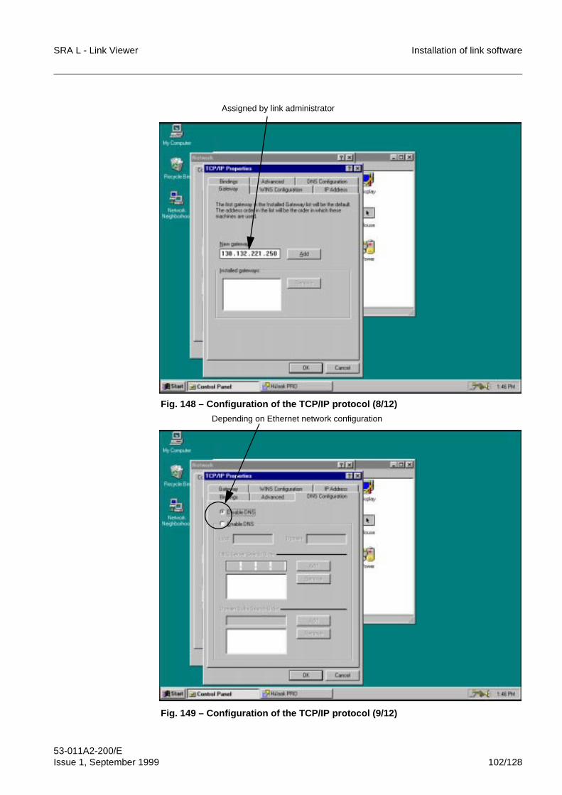
SRA L - Link Viewer Installation of link software
53-011A2-200/EIssue 1, September 1999 102/128
Fig. 148 – Configuration of the TCP/IP protocol (8/12)
Fig. 149 – Configuration of the TCP/IP protocol (9/12)
Assigned by link administrator
Depending on Ethernet network configuration
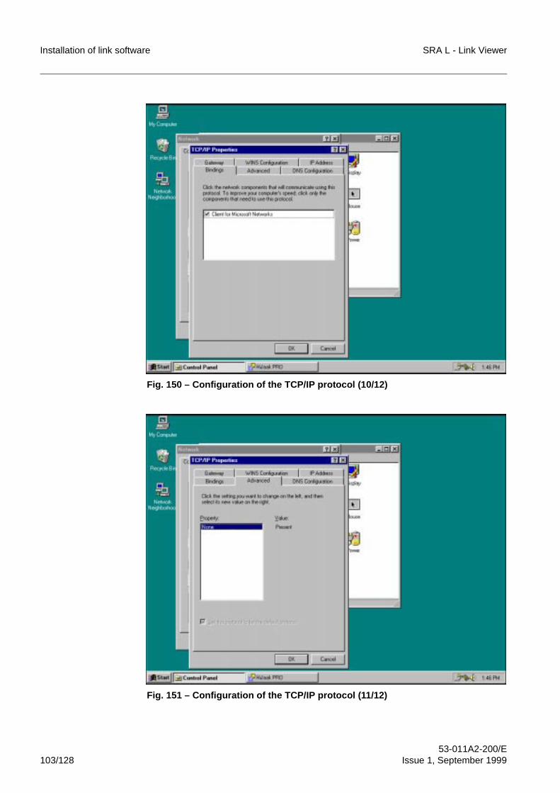
Installation of link software SRA L - Link Viewer
53-011A2-200/E103/128 Issue 1, September 1999
Fig. 150 – Configuration of the TCP/IP protocol (10/12)
Fig. 151 – Configuration of the TCP/IP protocol (11/12)
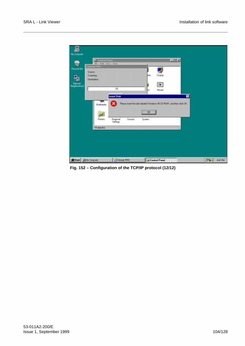
SRA L - Link Viewer Installation of link software
53-011A2-200/EIssue 1, September 1999 104/128
Fig. 152 – Configuration of the TCP/IP protocol (12/12)
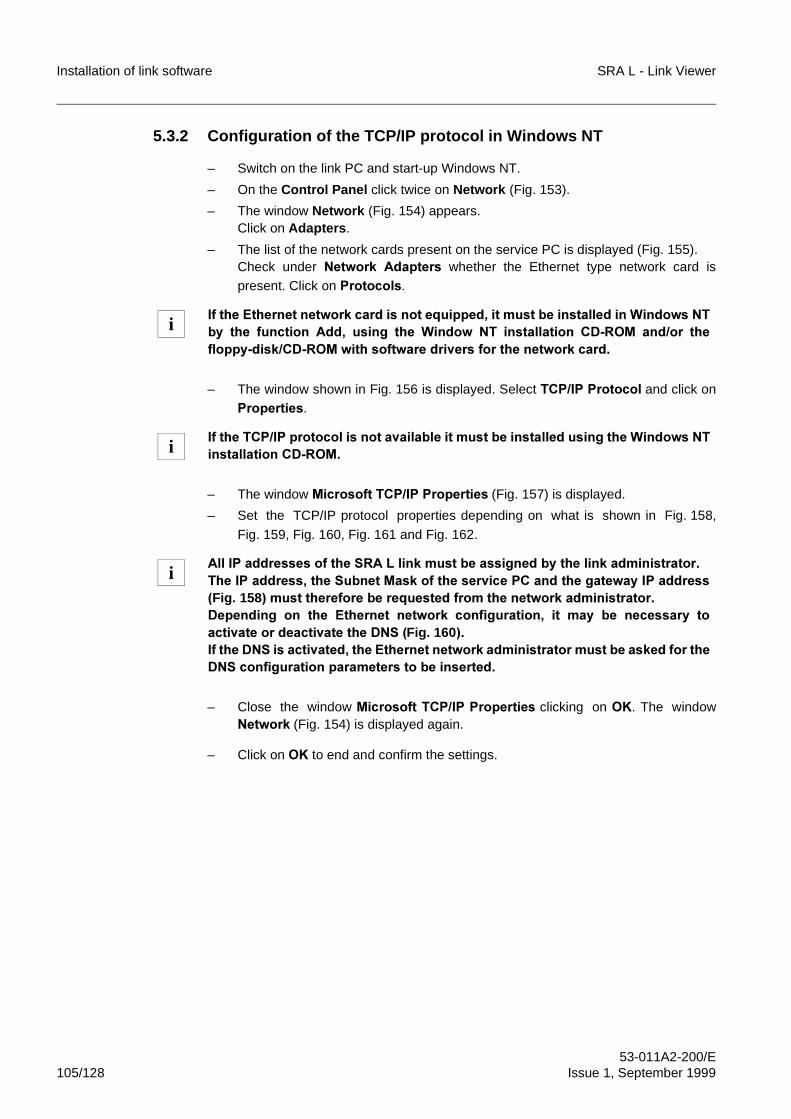
Installation of link software SRA L - Link Viewer
53-011A2-200/E105/128 Issue 1, September 1999
5.3.2 Configuration of the TCP/IP protocol in Windows NT
– Switch on the link PC and start-up Windows NT.
– On the Control Panel click twice on Network (Fig. 153).
– The window Network (Fig. 154) appears.Click on Adapters.
– The list of the network cards present on the service PC is displayed (Fig. 155).Check under 1HWZRUN� $GDSWHUV� whether� the Ethernet type network card ispresent. Click on 3URWRFROV.
– The window shown in Fig. 156 is displayed. Select 7&3�,3�3URWRFRO�and click on3URSHUWLHV.
– The window�0LFURVRIW�7&3�,3�3URSHUWLHV (Fig. 157) is displayed.
– Set the TCP/IP protocol properties depending on what is shown in Fig. 158,
Fig. 159, Fig. 160, Fig. 161 and Fig. 162.
– Close the window 0LFURVRIW�7&3�,3�3URSHUWLHV clicking on 2.. The window1HWZRUN (Fig. 154) is displayed again.
– Click on 2. to end and confirm the settings.
,I�WKH�(WKHUQHW�QHWZRUN�FDUG�LV�QRW�HTXLSSHG��LW�PXVW�EH�LQVWDOOHG�LQ�:LQGRZV�17E\� WKH� IXQFWLRQ� $GG�� XVLQJ� WKH� :LQGRZ� 17� LQVWDOODWLRQ� &'�520� DQG�RU� WKHIORSS\�GLVN�&'�520�ZLWK�VRIWZDUH�GULYHUV�IRU�WKH�QHWZRUN�FDUG�
,I�WKH�7&3�,3�SURWRFRO�LV�QRW�DYDLODEOH�LW�PXVW�EH�LQVWDOOHG�XVLQJ�WKH�:LQGRZV�17LQVWDOODWLRQ�&'�520�
$OO�,3�DGGUHVVHV�RI�WKH�65$�/�OLQN�PXVW�EH�DVVLJQHG�E\�WKH�OLQN�DGPLQLVWUDWRU�7KH�,3�DGGUHVV��WKH�6XEQHW�0DVN�RI�WKH�VHUYLFH�3&�DQG�WKH�JDWHZD\�,3�DGGUHVV�Fig. 158��PXVW�WKHUHIRUH�EH�UHTXHVWHG�IURP�WKH�QHWZRUN�DGPLQLVWUDWRU�'HSHQGLQJ� RQ� WKH� (WKHUQHW� QHWZRUN� FRQILJXUDWLRQ�� LW� PD\� EH� QHFHVVDU\� WRDFWLYDWH�RU�GHDFWLYDWH�WKH�'16��Fig. 160��,I�WKH�'16�LV�DFWLYDWHG��WKH�(WKHUQHW�QHWZRUN�DGPLQLVWUDWRU�PXVW�EH�DVNHG�IRU�WKH'16�FRQILJXUDWLRQ�SDUDPHWHUV�WR�EH�LQVHUWHG�
i
i
i
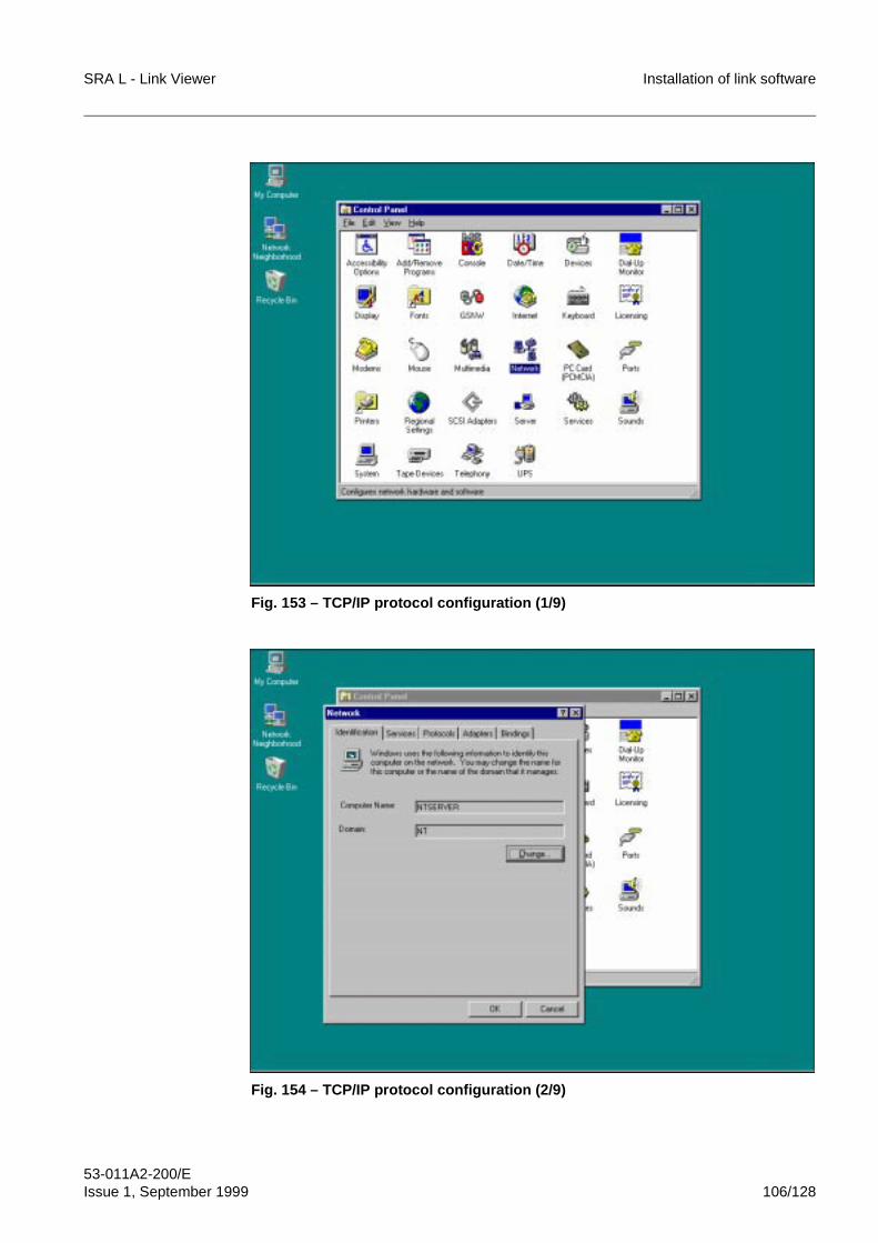
SRA L - Link Viewer Installation of link software
53-011A2-200/EIssue 1, September 1999 106/128
Fig. 153 – TCP/IP protocol configuration (1/9)
Fig. 154 – TCP/IP protocol configuration (2/9)
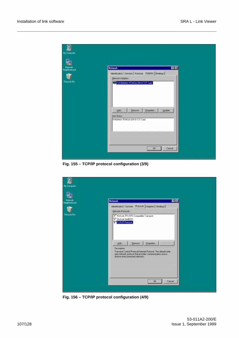
Installation of link software SRA L - Link Viewer
53-011A2-200/E107/128 Issue 1, September 1999
Fig. 155 – TCP/IP protocol configuration (3/9)
Fig. 156 – TCP/IP protocol configuration (4/9)
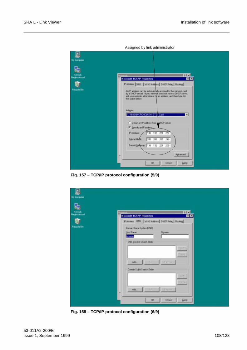
SRA L - Link Viewer Installation of link software
53-011A2-200/EIssue 1, September 1999 108/128
Fig. 157 – TCP/IP protocol configuration (5/9)
Fig. 158 – TCP/IP protocol configuration (6/9)
Assigned by link administrator
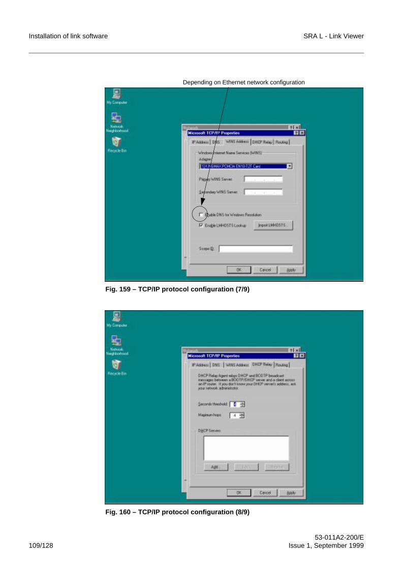
Installation of link software SRA L - Link Viewer
53-011A2-200/E109/128 Issue 1, September 1999
Fig. 159 – TCP/IP protocol configuration (7/9)
Fig. 160 – TCP/IP protocol configuration (8/9)
Depending on Ethernet network configuration
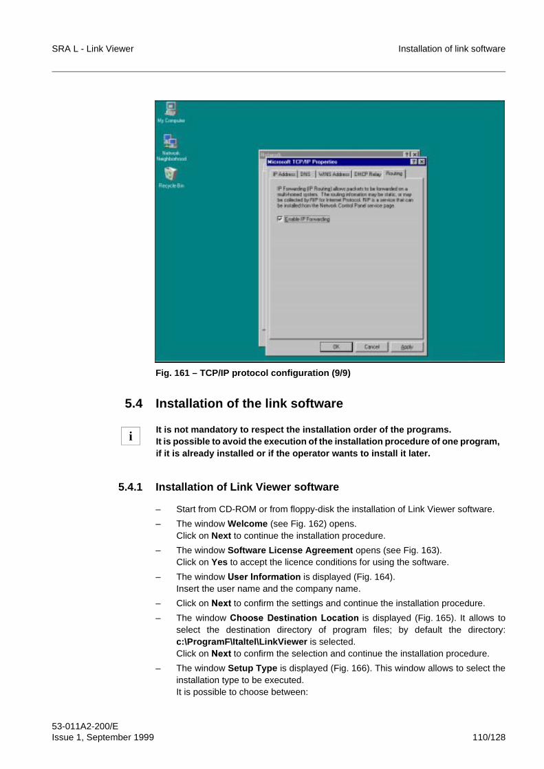
SRA L - Link Viewer Installation of link software
53-011A2-200/EIssue 1, September 1999 110/128
Fig. 161 – TCP/IP protocol configuration (9/9)
5.4 Installation of the link software
5.4.1 Installation of Link Viewer software
– Start from CD-ROM or from floppy-disk the installation of Link Viewer software.
– The window Welcome (see Fig. 162) opens. Click on Next to continue the installation procedure.
– The window Software License Agreement opens (see Fig. 163).Click on Yes to accept the licence conditions for using the software.
– The window 8VHU�,QIRUPDWLRQ is displayed (Fig. 164).Insert the user name and the company name.
– Click on 1H[W to confirm the settings and continue the installation procedure.
– The window &KRRVH�'HVWLQDWLRQ�/RFDWLRQ is displayed (Fig. 165). It allows toselect the destination directory of program files; by default the directory:c:\ProgramF\Italtel\LinkViewer�is selected.Click on 1H[W to confirm the selection and continue the installation procedure.
– The window Setup Type is displayed (Fig. 166). This window allows to select theinstallation type to be executed.It is possible to choose between:
It is not mandatory to respect the installation order of the programs.It is possible to avoid the execution of the installation procedure of one program,if it is already installed or if the operator wants to install it later.
i
Installation of link software SRA L - Link Viewer
53-011A2-200/E111/128 Issue 1, September 1999
• typical installation (7\SLFDO)• minumum installation (&RPSDFW)• custom installation (&XVWRP).By default, the typical installation is selected. Click on 1H[W to confirm the selectionand continue.
– If the custom installation has been chosen, the window &RPSRQHQWV�6HOHFWLRQ(Fig. 167) is displayed. This window allows to select the components to beinstalled. The following applications are available:• Link Viewer• Net Builder .By default both applications are selected. Click on 1H[W to confirm the selectionand continue.
– The�window 6HOHFW�3URJUDP�)ROGHU (Fig. 168) is displayed. Such a window allowsto select the name to be associated with the software folder in the 3URJUDPVmenu; by default /LQN�9LHZHU�����is selected.Click on 1H[W to confirm the selection and continue the installation.
– After completion of the file copying procedure, the final window Setup Completeof the installation program (Fig. 169) is displayed. Click on� )LQLVK to close thewindow and exit.
– At the end of installation, the new program folder LinkViewer3.0 is created inProgram Manager (see Fig. 170), if the installation is completed, the followingicons are created:• UnInstaller• Link Viewer• Net Builder.
7\SLFDO� LQVWDOODWLRQ� LV� XVXDOO\� UHFRPPHQGHG� IRU� QRUPDO� XVHUV�� WKH� FXVWRPLQVWDOODWLRQ�LV�DGYLVDEOH�IRU�DGYDQFHG�XVHUV�i
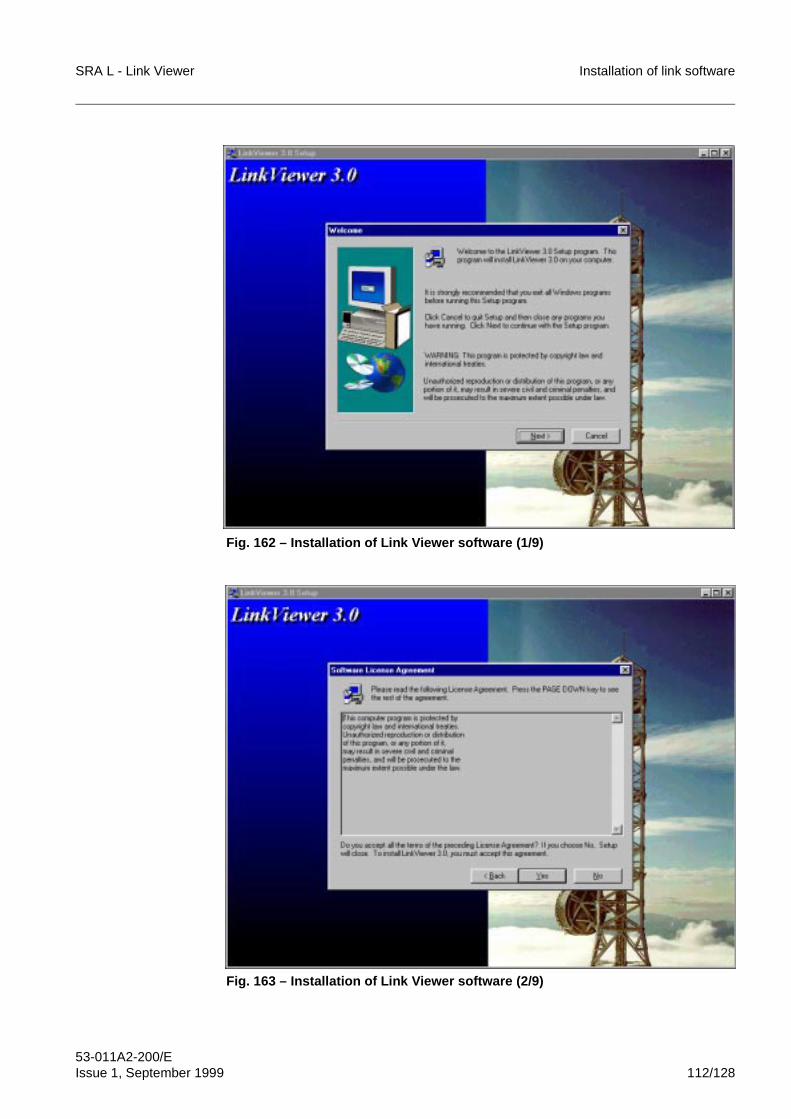
SRA L - Link Viewer Installation of link software
53-011A2-200/EIssue 1, September 1999 112/128
Fig. 162 – Installation of Link Viewer software (1/9)
Fig. 163 – Installation of Link Viewer software (2/9)
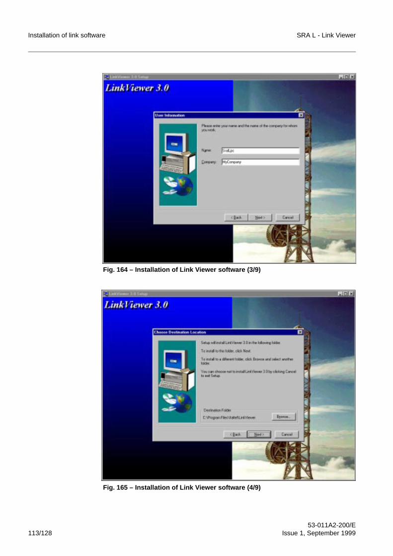
Installation of link software SRA L - Link Viewer
53-011A2-200/E113/128 Issue 1, September 1999
Fig. 164 – Installation of Link Viewer software (3/9)
Fig. 165 – Installation of Link Viewer software (4/9)
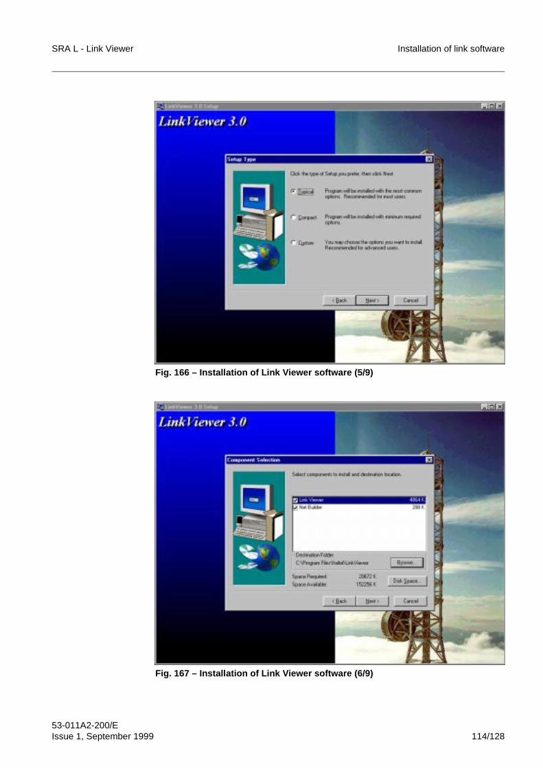
SRA L - Link Viewer Installation of link software
53-011A2-200/EIssue 1, September 1999 114/128
Fig. 166 – Installation of Link Viewer software (5/9)
Fig. 167 – Installation of Link Viewer software (6/9)
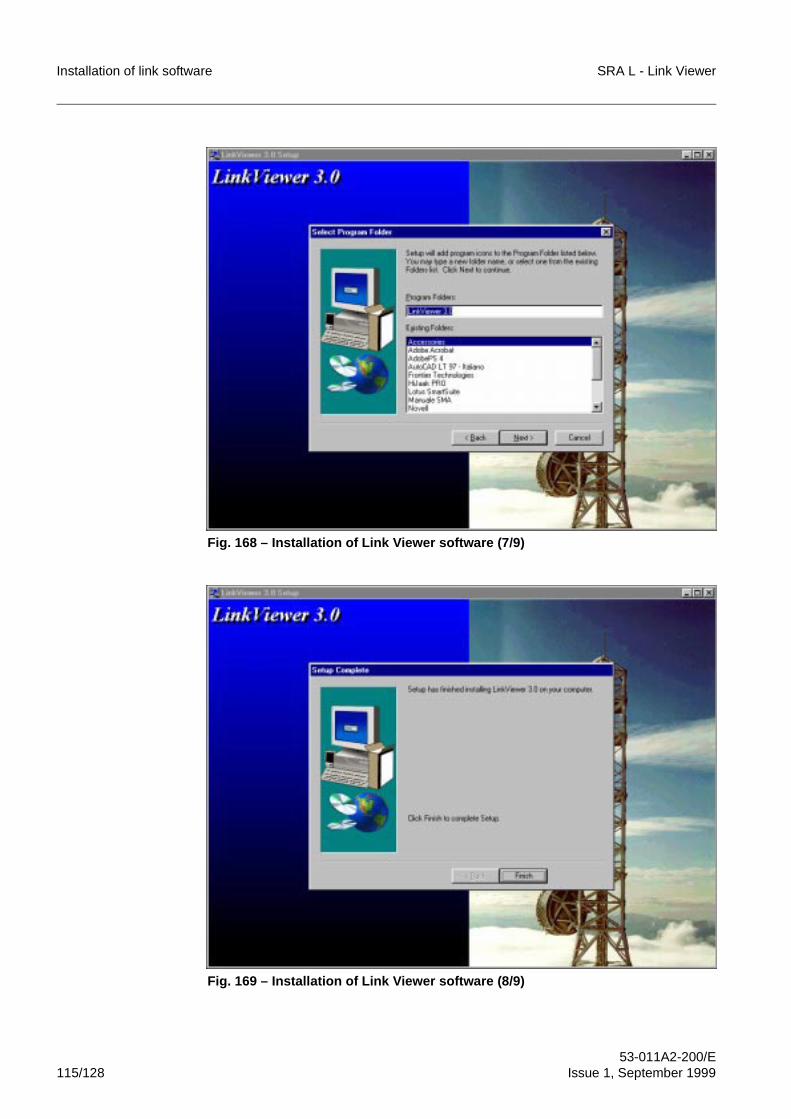
Installation of link software SRA L - Link Viewer
53-011A2-200/E115/128 Issue 1, September 1999
Fig. 168 – Installation of Link Viewer software (7/9)
Fig. 169 – Installation of Link Viewer software (8/9)
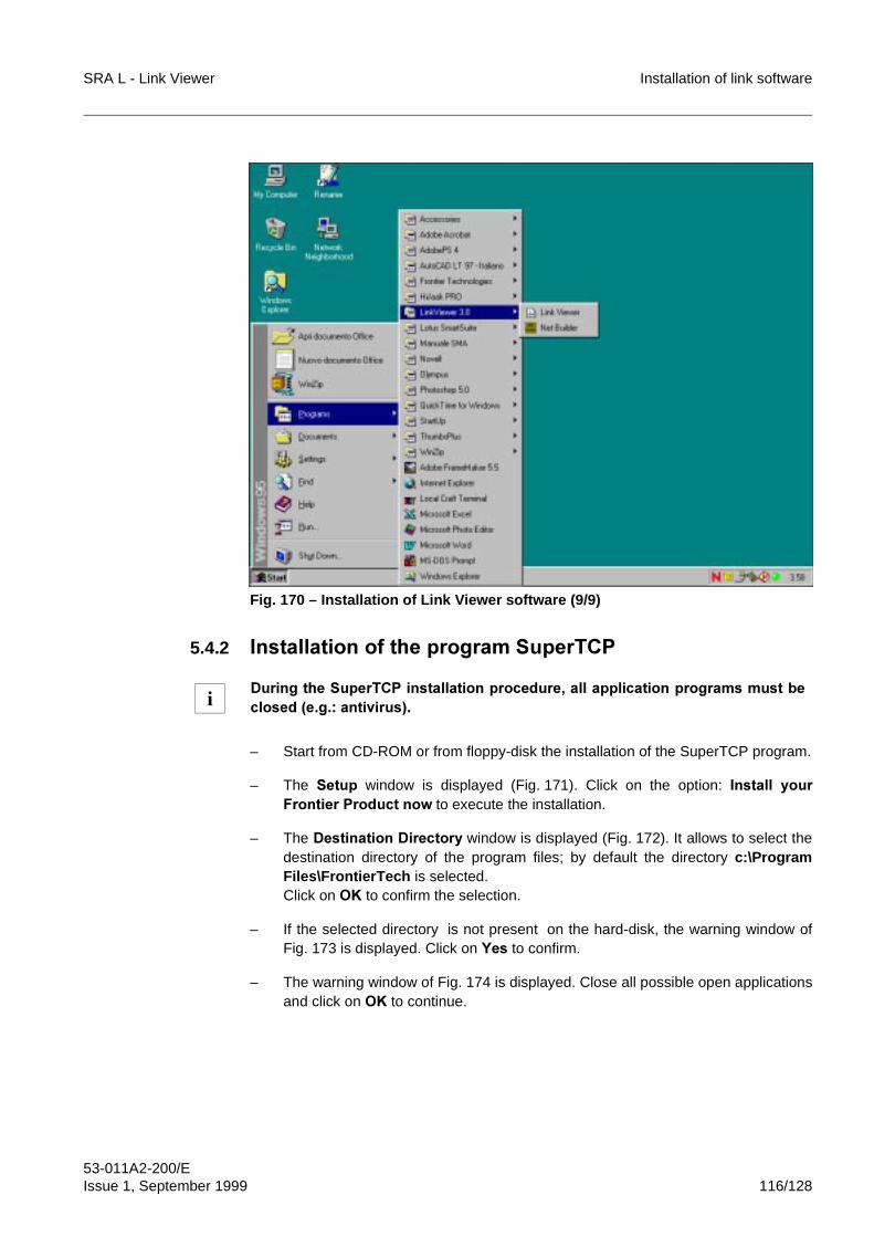
SRA L - Link Viewer Installation of link software
53-011A2-200/EIssue 1, September 1999 116/128
Fig. 170 – Installation of Link Viewer software (9/9)
5.4.2 ,QVWDOODWLRQ�RI�WKH�SURJUDP�6XSHU7&3
– Start from CD-ROM or from floppy-disk the installation of the SuperTCP program.
– The 6HWXS window is displayed (Fig. 171). Click on the option: ,QVWDOO� \RXU)URQWLHU�3URGXFW�QRZ to execute the installation.
– The 'HVWLQDWLRQ�'LUHFWRU\�window is displayed (Fig. 172). It allows to select thedestination directory of the program files; by default the directory c:\ProgramFiles\FrontierTech is selected.Click on 2. to confirm the selection.
– If the selected directory is not present on the hard-disk, the warning window ofFig. 173 is displayed. Click on <HV to confirm.
– The warning window of Fig. 174 is displayed. Close all possible open applicationsand click on 2. to continue.
'XULQJ�WKH�6XSHU7&3�LQVWDOODWLRQ�SURFHGXUH��DOO�DSSOLFDWLRQ�SURJUDPV�PXVW�EHFORVHG��H�J���DQWLYLUXV��i
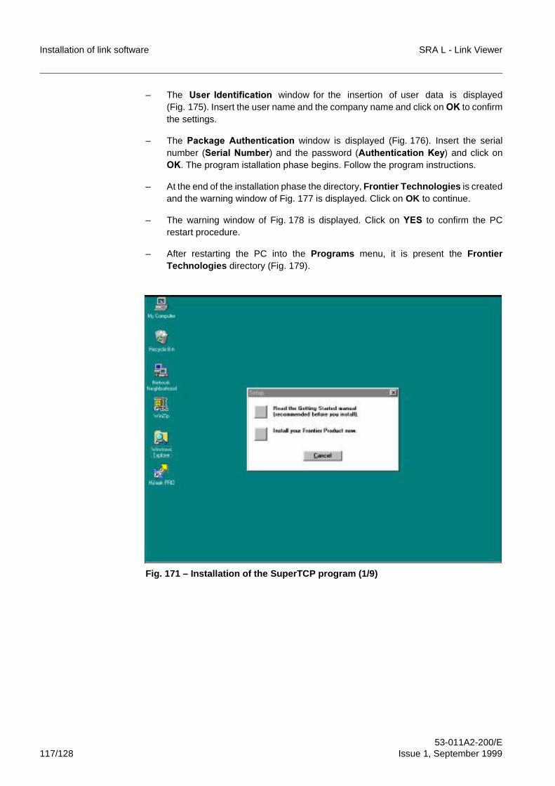
Installation of link software SRA L - Link Viewer
53-011A2-200/E117/128 Issue 1, September 1999
– The 8VHU� ,GHQWLILFDWLRQ window for the insertion of user data is displayed(Fig. 175). Insert the user name and the company name and click on 2. to confirmthe settings.
– The 3DFNDJH� $XWKHQWLFDWLRQ window is displayed (Fig. 176). Insert the serialnumber (6HULDO�1XPEHU) and the password ($XWKHQWLFDWLRQ�.H\) and click on2.. The program istallation phase begins. Follow the program instructions.
– At the end of the installation phase the directory, Frontier Technologies is createdand the warning window of Fig. 177 is displayed. Click on OK to continue.
– The warning window of Fig. 178 is displayed. Click on <(6 to confirm the PCrestart procedure.
– After restarting the PC into the Programs menu, it is present the FrontierTechnologies directory (Fig. 179).
Fig. 171 – Installation of the SuperTCP program (1/9)
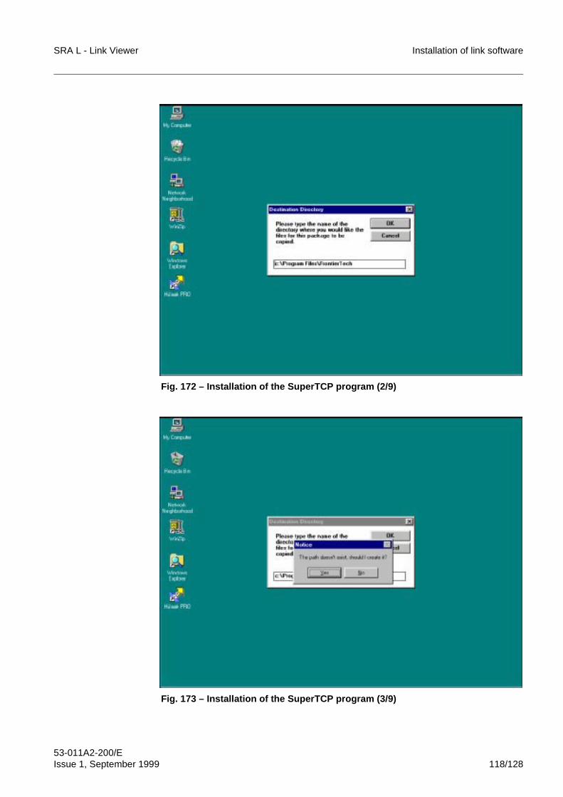
SRA L - Link Viewer Installation of link software
53-011A2-200/EIssue 1, September 1999 118/128
Fig. 172 – Installation of the SuperTCP program (2/9)
Fig. 173 – Installation of the SuperTCP program (3/9)
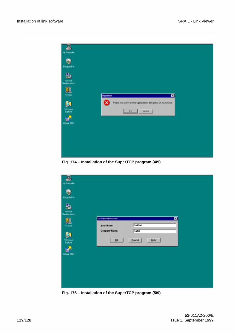
Installation of link software SRA L - Link Viewer
53-011A2-200/E119/128 Issue 1, September 1999
Fig. 174 – Installation of the SuperTCP program (4/9)
Fig. 175 – Installation of the SuperTCP program (5/9)
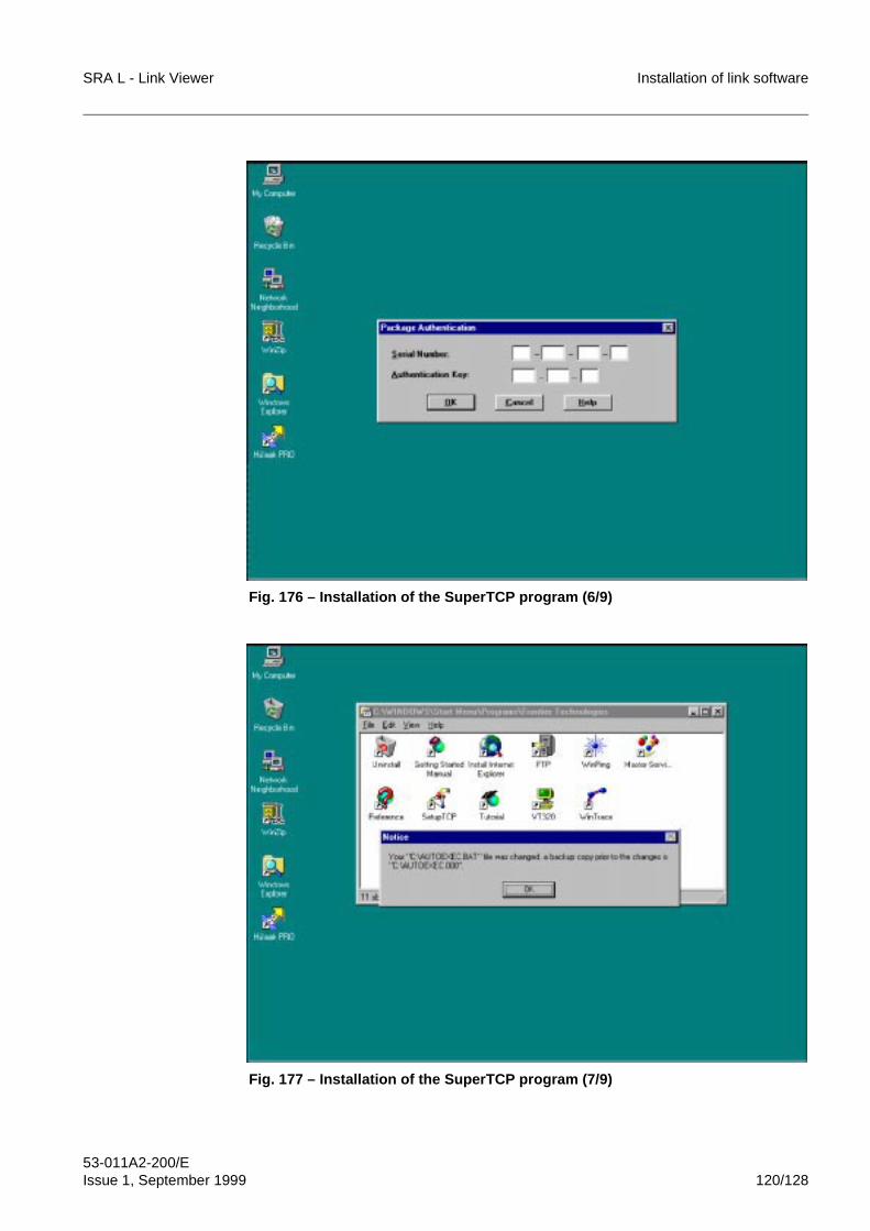
SRA L - Link Viewer Installation of link software
53-011A2-200/EIssue 1, September 1999 120/128
Fig. 176 – Installation of the SuperTCP program (6/9)
Fig. 177 – Installation of the SuperTCP program (7/9)
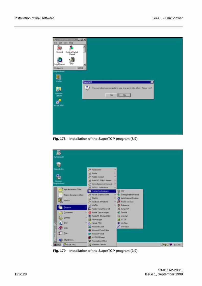
Installation of link software SRA L - Link Viewer
53-011A2-200/E121/128 Issue 1, September 1999
Fig. 178 – Installation of the SuperTCP program (8/9)
Fig. 179 – Installation of the SuperTCP program (9/9)
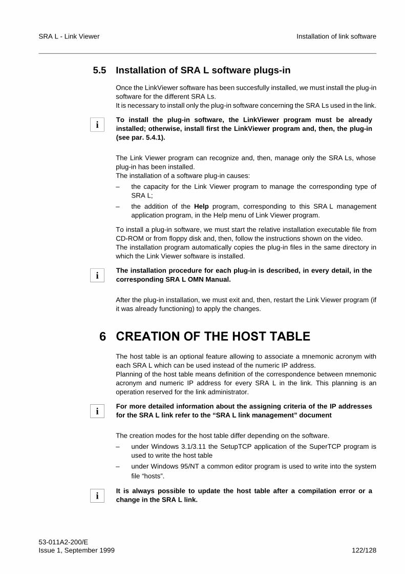
SRA L - Link Viewer Installation of link software
53-011A2-200/EIssue 1, September 1999 122/128
5.5 Installation of SRA L software plugs-in
Once the LinkViewer software has been succesfully installed, we must install the plug-insoftware for the different SRA Ls.It is necessary to install only the plug-in software concerning the SRA Ls used in the link.
The Link Viewer program can recognize and, then, manage only the SRA Ls, whoseplug-in has been installed.The installation of a software plug-in causes:
– the capacity for the Link Viewer program to manage the corresponding type ofSRA L;
– the addition of the Help program, corresponding to this SRA L managementapplication program, in the Help menu of Link Viewer program.
To install a plug-in software, we must start the relative installation executable file fromCD-ROM or from floppy disk and, then, follow the instructions shown on the video.The installation program automatically copies the plug-in files in the same directory inwhich the Link Viewer software is installed.
After the plug-in installation, we must exit and, then, restart the Link Viewer program (ifit was already functioning) to apply the changes.
6 &5($7,21�2)�7+(�+267�7$%/(
The host table is an optional feature allowing to associate a mnemonic acronym witheach SRA L which can be used instead of the numeric IP address.Planning of the host table means definition of the correspondence between mnemonicacronym and numeric IP address for every SRA L in the link. This planning is anoperation reserved for the link administrator.
The creation modes for the host table differ depending on the software.
– under Windows 3.1/3.11 the SetupTCP application of the SuperTCP program isused to write the host table
– under Windows 95/NT a common editor program is used to write into the systemfile “hosts”.
To install the plug-in software, the LinkViewer program must be alreadyinstalled; otherwise, install first the LinkViewer program and, then, the plug-in(see par. 5.4.1).
The installation procedure for each plug-in is described, in every detail, in thecorresponding SRA L OMN Manual.
For more detailed information about the assigning criteria of the IP addressesfor the SRA L link refer to the “SRA L link management” document
It is always possible to update the host table after a compilation error or achange in the SRA L link.
i
i
i
i
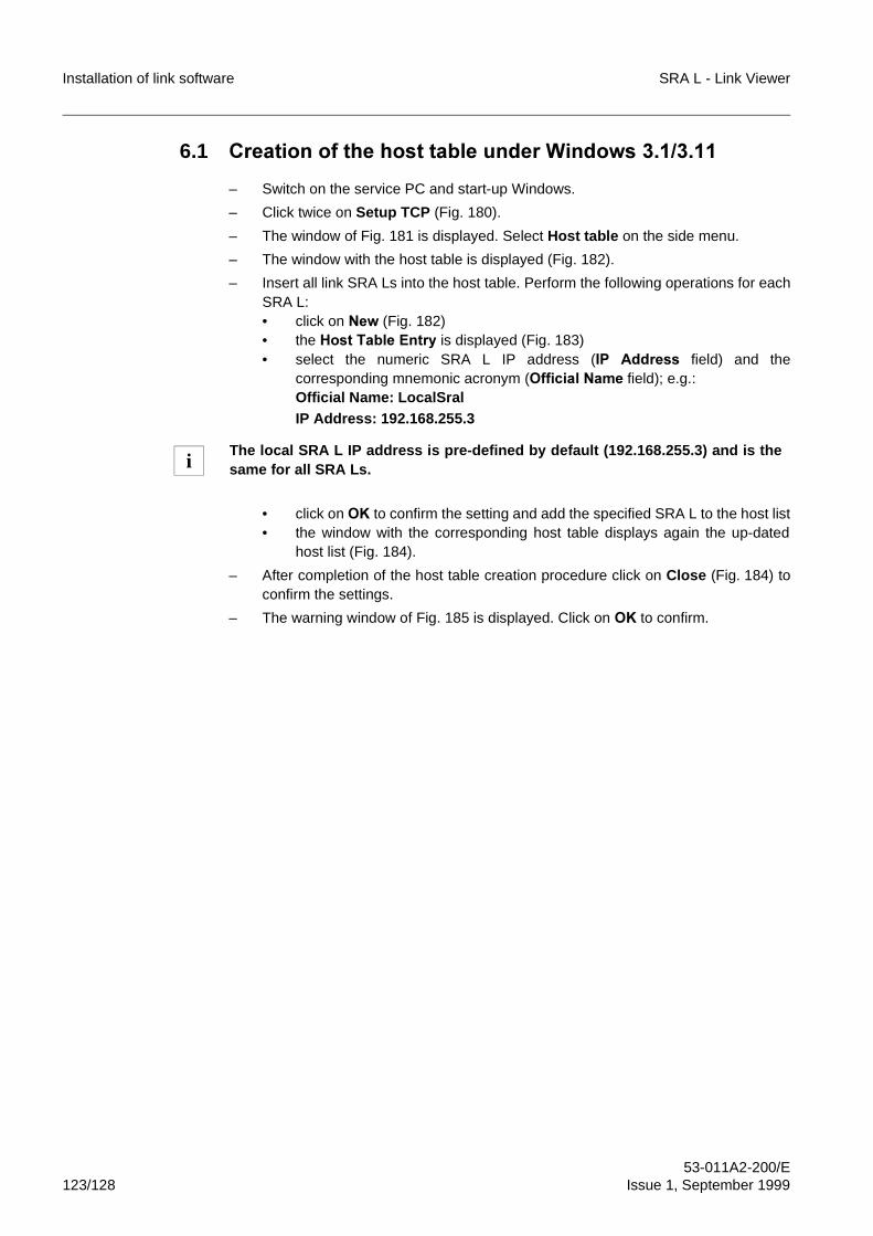
Installation of link software SRA L - Link Viewer
53-011A2-200/E123/128 Issue 1, September 1999
6.1 &UHDWLRQ�RI�WKH�KRVW�WDEOH�XQGHU�:LQGRZV���������
– Switch on the service PC and start-up Windows.
– Click twice on Setup TCP (Fig. 180).
– The window of Fig. 181 is displayed. Select Host table on the side menu.
– The window with the host table is displayed (Fig. 182).
– Insert all link SRA Ls into the host table. Perform the following operations for eachSRA L:• click on 1HZ�(Fig. 182)• the +RVW�7DEOH�(QWU\�is displayed (Fig. 183)• select the numeric SRA L IP address (,3 $GGUHVV field) and the
corresponding mnemonic acronym (2IILFLDO�1DPH field); e.g.:Official Name: LocalSralIP Address: 192.168.255.3
• click on 2. to confirm the setting and add the specified SRA L to the host list• the window with the corresponding host table displays again the up-dated
host list (Fig. 184).
– After completion of the host table creation procedure click on Close (Fig. 184) toconfirm the settings.
– The warning window of Fig. 185 is displayed. Click on 2.�to confirm.
The local SRA L IP address is pre-defined by default (192.168.255.3) and is thesame for all SRA Ls.i
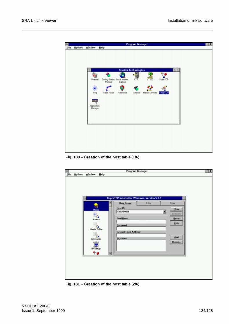
SRA L - Link Viewer Installation of link software
53-011A2-200/EIssue 1, September 1999 124/128
Fig. 180 – &UHDWLRQ�RI�WKH�KRVW�WDEOH (1/6)
Fig. 181 – &UHDWLRQ�RI�WKH�KRVW�WDEOH (2/6)
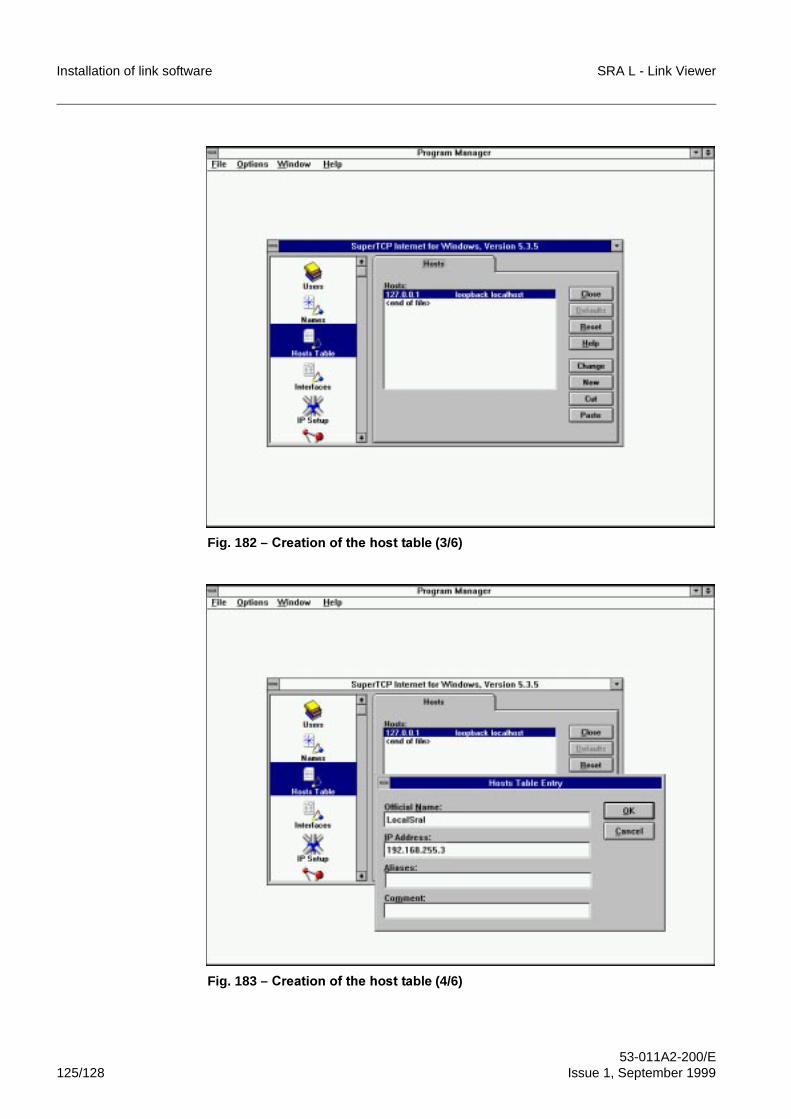
Installation of link software SRA L - Link Viewer
53-011A2-200/E125/128 Issue 1, September 1999
Fig. 182 – &UHDWLRQ�RI�WKH�KRVW�WDEOH (3/6)
Fig. 183 – &UHDWLRQ�RI�WKH�KRVW�WDEOH (4/6)
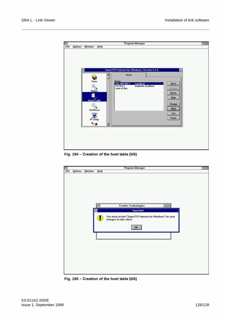
SRA L - Link Viewer Installation of link software
53-011A2-200/EIssue 1, September 1999 126/128
Fig. 184 – &UHDWLRQ�RI�WKH�KRVW�WDEOH (5/6)
Fig. 185 – &UHDWLRQ�RI�WKH�KRVW�WDEOH (6/6)
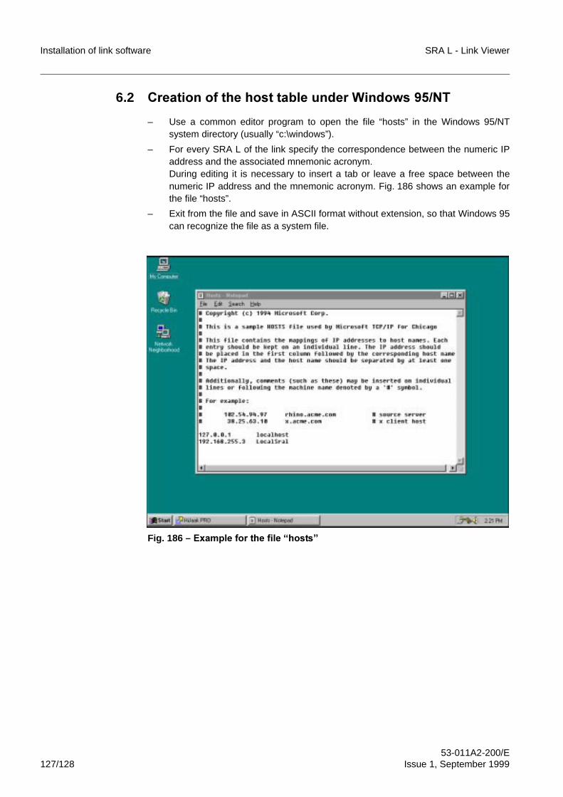
Installation of link software SRA L - Link Viewer
53-011A2-200/E127/128 Issue 1, September 1999
6.2 &UHDWLRQ�RI�WKH�KRVW�WDEOH�XQGHU�:LQGRZV����17
– Use a common editor program to open the file “hosts” in the Windows 95/NTsystem directory (usually “c:\windows”).
– For every SRA L of the link specify the correspondence between the numeric IPaddress and the associated mnemonic acronym. During editing it is necessary to insert a tab or leave a free space between thenumeric IP address and the mnemonic acronym. Fig. 186 shows an example forthe file “hosts”.
– Exit from the file and save in ASCII format without extension, so that Windows 95can recognize the file as a system file.
Fig. 186 – ([DPSOH�IRU�WKH�ILOH�³KRVWV´

SRA L - Link Viewer Installation of link software
53-011A2-200/EIssue 1, September 1999 128/128
FINE
BLANK PAGE
SRA L - Link ViewerSystem for SRA L management
Connection to SRA L link
53-011A2-201/EIssue 1, September 1999

Connection to SRA L link SRA L - Link Viewer
53-011A2-201/E2/52 Issue 1, September 1999
BLANK PAGE
SRA L - Link Viewer Connection to SRA L link
53-011A2-201/EIssue 1, September 1999 3/52
Contents
1 OVERVIEW . . . . . . . . . . . . . . . . . . . . . . . . . . . . . . . . . . . . . . . . . . . . . . . . . 6
2 MODES OF CONNECTION BETWEEN THE SERVICE PC AND THE SRA L LINK . . . . . . . . . . . . . . . . . . . . . . . . . . . . . . . . . . . . . . . . . . . . . . . . . 6
2.1 Direct connection on RS-232C serial interface . . . . . . . . . . . . . . . . . . . . . . . 62.1.1 Overview . . . . . . . . . . . . . . . . . . . . . . . . . . . . . . . . . . . . . . . . . . . . . . . . . . . . 62.1.2 Requirements of RS-232C serial cable. . . . . . . . . . . . . . . . . . . . . . . . . . . . . 72.2 Remote connection on RS-232C serial interface . . . . . . . . . . . . . . . . . . . . . 82.2.1 Overview . . . . . . . . . . . . . . . . . . . . . . . . . . . . . . . . . . . . . . . . . . . . . . . . . . . . 82.2.2 Characteristics of the connection cables . . . . . . . . . . . . . . . . . . . . . . . . . . . 92.2.3 Characteristics and configuration of modems. . . . . . . . . . . . . . . . . . . . . . . . 92.2.3.1 Modem characteristics . . . . . . . . . . . . . . . . . . . . . . . . . . . . . . . . . . . . . . . . . 92.2.3.2 Modem configuration . . . . . . . . . . . . . . . . . . . . . . . . . . . . . . . . . . . . . . . . . . 92.3 Remote connection on Ethernet interface via router. . . . . . . . . . . . . . . . . . 112.4 Remote connection on Ethernet interface by Server Proxy . . . . . . . . . . . . 12
3 ACTIVATION OF CONNECTION BETWEEN SERVICE PC AND SRA L LINK 13
3.1 Activation of dial-up connection to SRA L link in Windows 3.1/3.11 . . . . . . 133.2 Activation of the dial-up connection to the SRA L in Windows 95 . . . . . . . 183.3 Activation of the dial-up connection to SRA L in Windows NT . . . . . . . . . . 23
4 LOADING OF SRA L CONFIGURATION FILE . . . . . . . . . . . . . . . . . . . . . 324.1 Map opening . . . . . . . . . . . . . . . . . . . . . . . . . . . . . . . . . . . . . . . . . . . . . . . . 324.2 Access towards SRA L . . . . . . . . . . . . . . . . . . . . . . . . . . . . . . . . . . . . . . . . 34
5 ROUTING TROUBLES WITH THE TCP/IP PACKETS IN WINDOWS 95/NT . . . . . . . . . . . . . . . . . . . . . . . . . . . . . . . . . . . . . . . . . . . . . . . . . . . . . 36
5.1 Common cases of TCP/IP packet routing. . . . . . . . . . . . . . . . . . . . . . . . . . 365.2 Commands to solve reachability problems . . . . . . . . . . . . . . . . . . . . . . . . . 385.2.1 The “winipcfg” command. . . . . . . . . . . . . . . . . . . . . . . . . . . . . . . . . . . . . . . 385.2.2 Dial-up monitor window in Windows NT . . . . . . . . . . . . . . . . . . . . . . . . . . . 395.2.3 The “ipconfig” command . . . . . . . . . . . . . . . . . . . . . . . . . . . . . . . . . . . . . . . 405.2.4 The “route print” command . . . . . . . . . . . . . . . . . . . . . . . . . . . . . . . . . . . . . 415.2.5 The “route add” command . . . . . . . . . . . . . . . . . . . . . . . . . . . . . . . . . . . . . 415.2.6 WinTrace utility of the Frontier Technologies software . . . . . . . . . . . . . . . . 425.2.7 The “tracert” command . . . . . . . . . . . . . . . . . . . . . . . . . . . . . . . . . . . . . . . . 43
6 TROUBLES IN THE DIAL-UP CONNECTION TO THE LOCAL EQUIPMENT . . . . . . . . . . . . . . . . . . . . . . . . . . . . . . . . . . . . . . . . . . . . . . . 44
6.1 Local equipment not reacheable using the default local IP address. . . . . . 446.2 Deactivation of the dial-up connection for traffic absence in Windows NT . 446.3 Detection of the local equipment IP address . . . . . . . . . . . . . . . . . . . . . . . 466.3.1 Individuazione dell’indirizzo IP dell’apparato locale in Windows 3.1/3.11. . 466.3.2 Detection of the local equipment IP address in Windows 95 . . . . . . . . . . . 496.3.3 Detection of the local equipment IP address in Windows NT . . . . . . . . . . . 51
Connection to SRA L link SRA L - Link Viewer
53-011A2-201/E4/52 Issue 1, September 1999
IllustrationsFig. 1 Direct connection on RS-232C serial interface . . . . . . . . . . . . . . . . . . . . . . . 6
Fig. 2 RS-232C connecting cable between SRA L and service PC. . . . . . . . . . . . . 7
Fig. 3 Connection on RS-232C serial interface . . . . . . . . . . . . . . . . . . . . . . . . . . . . 8
Fig. 4 Remote connection on Ethernet interface by router. . . . . . . . . . . . . . . . . . . 11
Fig. 5 Remote connection on Ethernet interface by Server Proxy . . . . . . . . . . . . . 12
Fig. 6 Activation of dial-up connection to SRA L in Windows 3.1/3.11 (1/7) . . . . . 14
Fig. 7 Activation of dial-up connection to SRA L in Windows 3.1/3.11 (2/7) . . . . . 15
Fig. 8 Activation of dial-up connection to SRA L in Windows 3.1/3.11 (3/7) . . . . . 15
Fig. 9 Activation of dial-up connection to SRA L in Windows 3.1/3.11 (4/7) . . . . . 16
Fig. 10 Activation of dial-up connection to SRA L in Windows 3.1/3.11 (5/7) . . . . . 16
Fig. 11 Activation of dial-up connection to SRA L in Windows 3.1/3.11 (6/7) . . . . . 17
Fig. 12 Activation of dial-up connection to SRA L in Windows 3.1/3.11 (7/7) . . . . . 17
Fig. 13 Activation of dial-up connection to SRA L in Windows 95 (1/8) . . . . . . . . . . 19
Fig. 14 Activation of dial-up connection to SRA L in Windows 95 (2/8) . . . . . . . . . . 19
Fig. 15 Activation of dial-up connection to SRA L in Windows 95 (3/8) . . . . . . . . . . 20
Fig. 16 Activation of dial-up connection to SRA L in Windows 95 (4/8) . . . . . . . . . . 20
Fig. 17 Activation of dial-up connection to SRA L in Windows 95 (5/8) . . . . . . . . . . 21
Fig. 18 Activation of dial-up connection to SRA L in Windows 95 (6/8) . . . . . . . . . . 21
Fig. 19 Activation of dial-up connection to SRA L in Windows 95 (7/8) . . . . . . . . . . 22
Fig. 20 Activation of dial-up connection to SRA L in Windows 95 (8/8) . . . . . . . . . . 22
Fig. 21 Activation of the dial-up connection to SRA L in Windows NT (1/13) . . . . . 24
Fig. 22 Activation of the dial-up connection to SRA L in Windows NT (2/13) . . . . . 25
Fig. 23 Activation of the dial-up connection to SRA L in Windows NT (3/13) . . . . . 25
Fig. 24 Activation of the dial-up connection to SRA L in Windows NT (4/13) . . . . . 26
Fig. 25 Activation of the dial-up connection to SRA L in Windows NT (5/13) . . . . . 26
Fig. 26 Activation of the dial-up connection to SRA L in Windows NT (6/13) . . . . . 27
Fig. 27 Activation of the dial-up connection to SRA L in Windows NT (7/13) . . . . . 27
Fig. 28 Activation of the dial-up connection to SRA L in Windows NT (8/13) . . . . . 28
Fig. 29 Activation of the dial-up connection to SRA L in Windows NT (9/13) . . . . . 28
Fig. 30 Activation of the dial-up connection to SRA L in Windows NT (10/13) . . . . 29
Fig. 31 Activation of the dial-up connection to SRA L in Windows NT (11/13) . . . . 29
Fig. 32 Activation of the dial-up connection to SRA L in Windows NT (12/13) . . . . 30
Fig. 33 Activation of the dial-up connection to SRA L in Windows NT (13/13) . . . . 30
Fig. 34 Closing of the dial-up connection to SRA L in Windows NT . . . . . . . . . . . . 31
Fig. 35 Window for map Security . . . . . . . . . . . . . . . . . . . . . . . . . . . . . . . . . . . . . . . 33
Fig. 36 Example of local map. . . . . . . . . . . . . . . . . . . . . . . . . . . . . . . . . . . . . . . . . . 33
Fig. 37 Window of the loading of SRA L configuration file . . . . . . . . . . . . . . . . . . . . 34
Fig. 38 Security window . . . . . . . . . . . . . . . . . . . . . . . . . . . . . . . . . . . . . . . . . . . . . . 35
Fig. 39 User class selection window . . . . . . . . . . . . . . . . . . . . . . . . . . . . . . . . . . . . 35
Fig. 40 Window for password insertion . . . . . . . . . . . . . . . . . . . . . . . . . . . . . . . . . . 35
Fig. 41 Forcing of “Use default gateway on remote network” option in Windows 9537
Fig. 42 Forcing of “Use default gateway on remote network” option in Windows
NT . . . . . . . . . . . . . . . . . . . . . . . . . . . . . . . . . . . . . . . . . . . . . . . . . . . . . . . . 37
SRA L - Link Viewer Connection to SRA L link
53-011A2-201/EIssue 1, September 1999 5/52
Fig. 43 The “winipcfg” command. . . . . . . . . . . . . . . . . . . . . . . . . . . . . . . . . . . . . . . 38
Fig. 44 Dial-up monitor window in Windows NT . . . . . . . . . . . . . . . . . . . . . . . . . . . 39
Fig. 45 The “ipconfig” command . . . . . . . . . . . . . . . . . . . . . . . . . . . . . . . . . . . . . . . 40
Fig. 46 The “route print” command . . . . . . . . . . . . . . . . . . . . . . . . . . . . . . . . . . . . . 41
Fig. 47 WinTrace utility . . . . . . . . . . . . . . . . . . . . . . . . . . . . . . . . . . . . . . . . . . . . . . 42
Fig. 48 The “tracert” command . . . . . . . . . . . . . . . . . . . . . . . . . . . . . . . . . . . . . . . . 43
Fig. 49 “ping –t” command in Windows NT. . . . . . . . . . . . . . . . . . . . . . . . . . . . . . . 45
Fig. 50 RAS monitor icon in the system application box in Windows NT . . . . . . . . 45
Fig. 51 Reset of the dial-up connection in Windows NT . . . . . . . . . . . . . . . . . . . . . 46
Fig. 52 Detection of the local equipment IP address in Windows 3.1/3.11 (1/4). . . 47
Fig. 53 Detection of the local equipment IP address in Windows 3.1/3.11 (2/4). . . 47
Fig. 54 Detection of the local equipment IP address in Windows 3.1/3.11 (3/4). . . 48
Fig. 55 Detection of the local equipment IP address in Windows 3.1/3.11 (4/4). . . 48
Fig. 56 Detection of the local equipment IP address in Windows 95 (1/3) . . . . . . . 49
Fig. 57 Detection of the local equipment IP address in Windows 95 (2/3) . . . . . . . 50
Fig. 58 Detection of the local equipment IP address in Windows 95 (3/3) . . . . . . . 50
Fig. 59 Detection of the local equipment IP address in Windows NT (1/3). . . . . . . 51
Fig. 60 Detection of the local equipment IP address in Windows NT (2/3). . . . . . . 52
Fig. 61 Detection of the local equipment IP address in Windows NT (3/3). . . . . . . 52
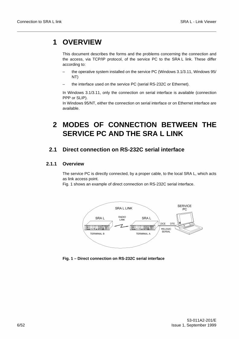
Connection to SRA L link SRA L - Link Viewer
53-011A2-201/E6/52 Issue 1, September 1999
1 OVERVIEWThis document describes the forms and the problems concerning the connection andthe access, via TCP/IP protocol, of the service PC to the SRA L link. These differaccording to:
– the operative system installed on the service PC (Windows 3.1/3.11, Windows 95/NT)
– the interface used on the service PC (serial RS-232C or Ethernet).
In Windows 3.1/3.11, only the connection on serial interface is available (connectionPPP or SLIP).In Windows 95/NT, either the connection on serial interface or on Ethernet interface areavailable.
2 MODES OF CONNECTION BETWEEN THESERVICE PC AND THE SRA L LINK
2.1 Direct connection on RS-232C serial interface
2.1.1 Overview
The service PC is directly connected, by a proper cable, to the local SRA L, which actsas link access point.Fig. 1 shows an example of direct connection on RS-232C serial interface.
Fig. 1 – Direct connection on RS-232C serial interface
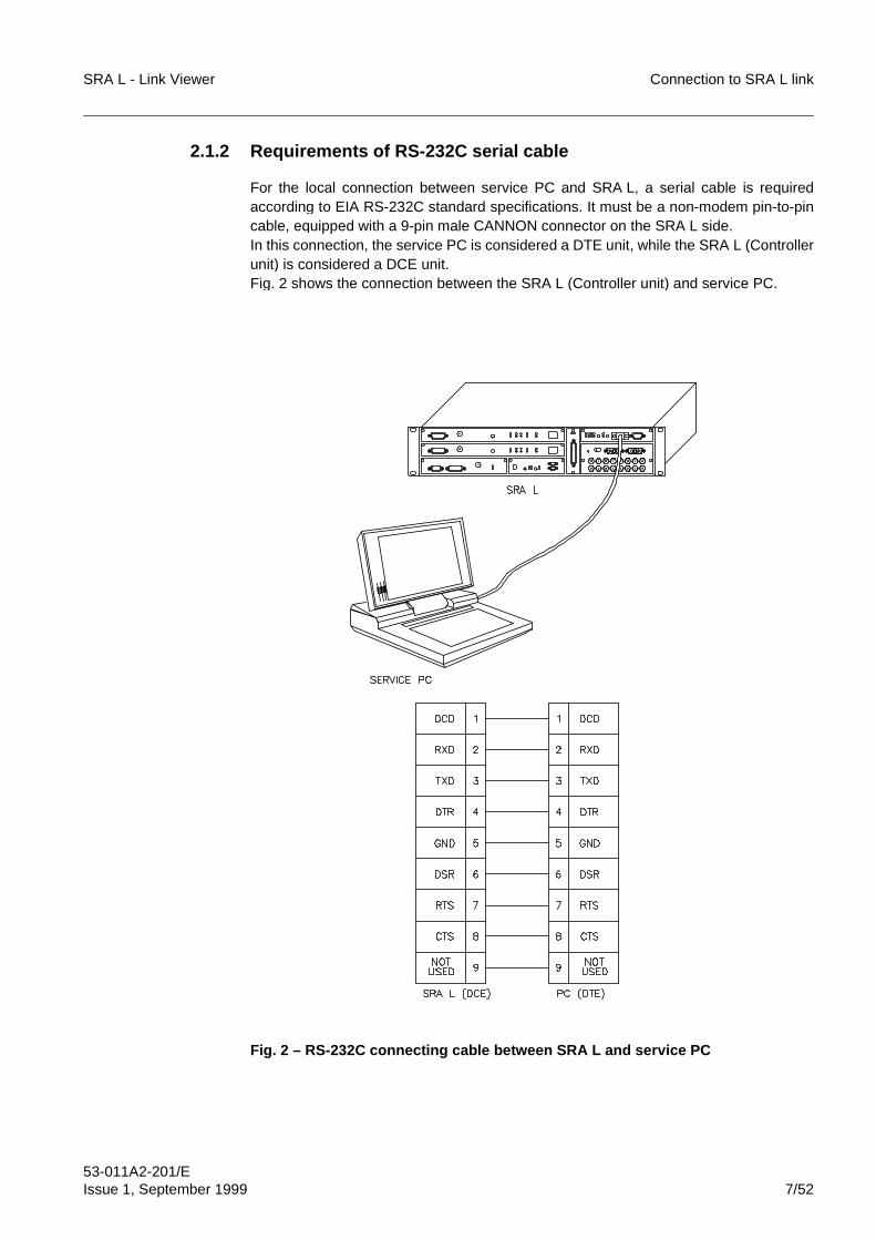
SRA L - Link Viewer Connection to SRA L link
53-011A2-201/EIssue 1, September 1999 7/52
2.1.2 Requirements of RS-232C serial cable
For the local connection between service PC and SRA L, a serial cable is requiredaccording to EIA RS-232C standard specifications. It must be a non-modem pin-to-pincable, equipped with a 9-pin male CANNON connector on the SRA L side.In this connection, the service PC is considered a DTE unit, while the SRA L (Controllerunit) is considered a DCE unit.Fig. 2 shows the connection between the SRA L (Controller unit) and service PC.
Fig. 2 – RS-232C connecting cable between SRA L and service PC
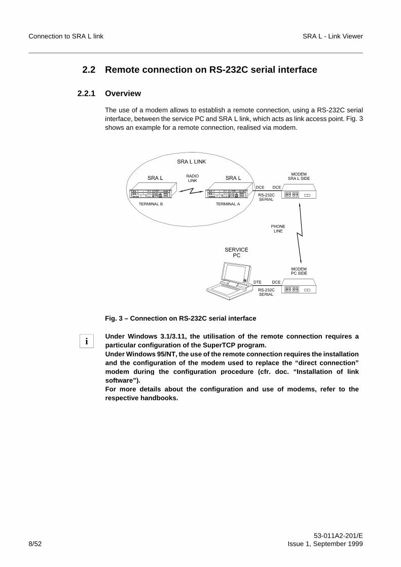
Connection to SRA L link SRA L - Link Viewer
53-011A2-201/E8/52 Issue 1, September 1999
2.2 Remote connection on RS-232C serial interface
2.2.1 Overview
The use of a modem allows to establish a remote connection, using a RS-232C serialinterface, between the service PC and SRA L link, which acts as link access point. Fig. 3shows an example for a remote connection, realised via modem.
Fig. 3 – Connection on RS-232C serial interface
Under Windows 3.1/3.11, the utilisation of the remote connection requires aparticular configuration of the SuperTCP program.Under Windows 95/NT, the use of the remote connection re quires the installationand the confi guration of the modem used to re place the “direct connection”modem durin g the confi guration procedure (cfr. doc. “Installation of linksoftware” ).For more details about the confi guration and use of modems, refer to therespective handbooks.
i
SRA L - Link Viewer Connection to SRA L link
53-011A2-201/EIssue 1, September 1999 9/52
2.2.2 Characteristics of the connection cables
The following is a list of requirements for the connection cables to be used:
– Connection between SRA L and modem.Use a standard cable for the DCE-DCE connection, because both SRA L andmodem are DCE units. The cable must be provided, on the SRA L side, with a 9-pinmale CANNON connector.
– Connection between PC (RS-232C serial port) and modem. Use a standard cable for the DTE-DCE connection, because the PC is a DTE unitand the modem is a DCE unit.
– Connection between modem and telephone line.The modem interface towards the telephone line is usually terminated with a 8-pinRJ45 standard jack.Some modems have two different interfaces (one for the switched line and one forthe dedicated line).
2.2.3 Characteristics and configuration of modems
2.2.3.1 Modem characteristics
The modems must be Hayes compatible and must support standard AT commands,with a minimum baud-rate of 19200 bps (SRA L transmission speed). This conditionrepresents a restriction for the entire system.In this case, the communication between modem and SRA L must run at 19200 bps,while a higher baud-rate can be used between modems, depending on the modemcharacteristics and the quality of the used line.
2.2.3.2 Modem configuration
The modem configuration can be performed:
– by PC, providing the modem with AT commands by means of a terminal emulatorsuch as the Windows 3.1/3.11 Terminal utility or the Windows 95 HyperTerminal.
– manually, using the modem control panel.
A variety of configurations, pre-defined by the manufacturer, is usually stored in themodem firmware. These cover a large field of applications.In this case, it is sufficient to load the most proper configuration according to the type ofused line (switched or dedicated) and to set the following commands:
– on modem, SRA L side:• disable every kind of flow control• disable every type of error correction, compression and auto-request• if a switched line is used, set the modem to auto-answer mode; this is usually
achieved by setting the AT command: “&S0=1”
– on modem, PC side:• disable every kind of flow control• disable every type of error correction, compression and auto-request
Connection to SRA L link SRA L - Link Viewer
53-011A2-201/E10/52 Issue 1, September 1999
• if a switched line is used, set the CDC control in such a way that it is ignoredin the current connection and returns to the command mode when the DTRsignal switches from “High” to “Low”; this is usually achieved by setting the ATcommand: “&C”
• if a switched line is used, set the DTR control in such a way that it is ignoredin the current connection and returns to the command mode when the DTRsignal changes from “High” to “Low”; this is usually achieved by setting the AT
command: “&D”.”
It is recommended to store the default configuration in the modem memory,using the AT command: “&W” (modems use the default configuration atstart-up).
i
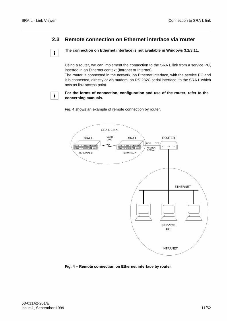
SRA L - Link Viewer Connection to SRA L link
53-011A2-201/EIssue 1, September 1999 11/52
2.3 Remote connection on Ethernet interface via router
Using a router, we can implement the connection to the SRA L link from a service PC,inserted in an Ethernet context (Intranet or Internet).The router is connected in the network, on Ethernet interface, with the service PC andit is connected, directly or via madem, on RS-232C serial interface, to the SRA L whichacts as link access point.
Fig. 4 shows an example of remote connection by router.
Fig. 4 – Remote connection on Ethernet interface by router
The connection on Ethernet interface is not available in Windows 3.1/3.11.
For the forms of connection, configuration and use of the router, refer to theconcerning manuals.
i
i
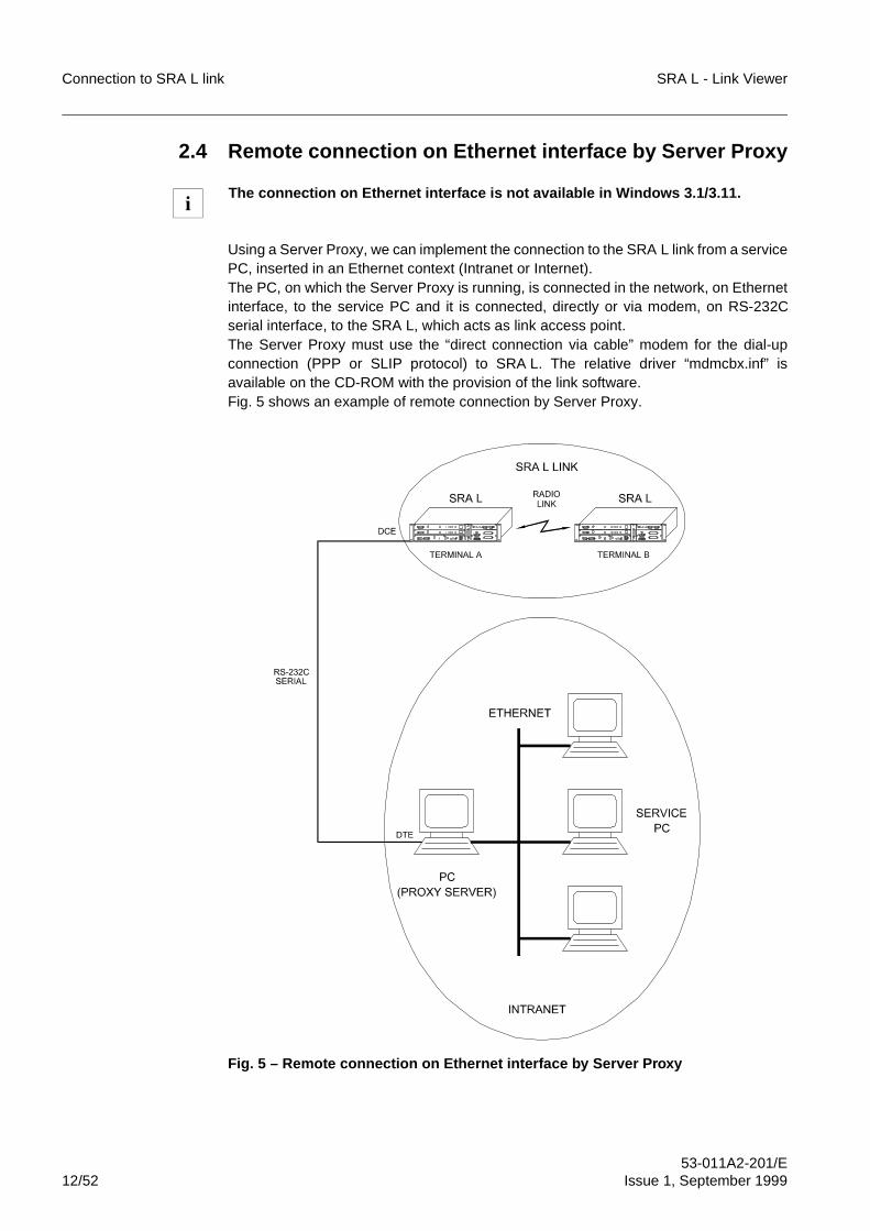
Connection to SRA L link SRA L - Link Viewer
53-011A2-201/E12/52 Issue 1, September 1999
2.4 Remote connection on Ethernet interface by Server Proxy
Using a Server Proxy, we can implement the connection to the SRA L link from a servicePC, inserted in an Ethernet context (Intranet or Internet).The PC, on which the Server Proxy is running, is connected in the network, on Ethernetinterface, to the service PC and it is connected, directly or via modem, on RS-232Cserial interface, to the SRA L, which acts as link access point.The Server Proxy must use the “direct connection via cable” modem for the dial-upconnection (PPP or SLIP protocol) to SRA L. The relative driver “mdmcbx.inf” isavailable on the CD-ROM with the provision of the link software.Fig. 5 shows an example of remote connection by Server Proxy.
Fig. 5 – Remote connection on Ethernet interface by Server Proxy
The connection on Ethernet interface is not available in Windows 3.1/3.11.i
SRA L - Link Viewer Connection to SRA L link
53-011A2-201/EIssue 1, September 1999 13/52
3 ACTIVATION OF CONNECTION BETWEENSERVICE PC AND SRA L LINKThe forms to activate the connection between the service PC and the SRA L, which actsas link access point, differ according to the interface types:
– RS-232 serial interfaceIt is necessary to activate the dial-up connection to SRA L on the service PC,before running the Link Viewer program.
– Ethernet interfaceThe connection between the service PC and the SRA L is automatically activatedduring Windows 95/NT start-up.
3.1 Activation of dial-up connection to SRA L link in Windows3.1/3.11
The procedure to realize the dial-up connection to SRA L in Windows 3.1/3.11 is thefollowing:
– Click twice on SuperTCP icon in the Frontier Technologies group (Fig. 6).
– The SuperTCP Kernel program window is displayed (Fig. 7).
– Select Messages in File menu of SuperTCP Kernel (Fig. 8).
– The SuperTCP Kernel window (Fig. 9) is displayed. In this window, the messagesare displayed, relevant to serial communication between service PC and SRA Llink. In case of correct functioning, the message displaying stops on Link O pen.Click on Done to close the message window.
Using a router for the connection on Ethernet interface, we must activate theconnection between router and SRA L, before running the Link Viewer program.
Using a Server Proxy for the connection on Ethernet interface, we must activatethe dial-up connection to SRA L on the PC on which the Server Proxy is inexecution, before running the Link Viewer program.
If a modem is used in the connection, the communication via modem must beactivated first.
☞ The followin g error messa ge is dis played:NEWT
unable to load library “NMPCIP.DLL”OK
if the o perator tries to use the TCP/IP protocol without havin g correctl y installedit. In this case, it is necessar y to install a gain the TCP/IP protocol (refer to“Installation of link software” document ).
i
i
i
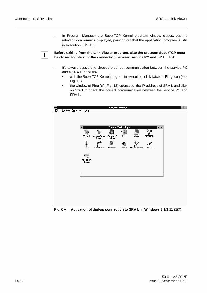
Connection to SRA L link SRA L - Link Viewer
53-011A2-201/E14/52 Issue 1, September 1999
– In Program Manager the SuperTCP Kernel program window closes, but therelevant icon remains displayed, pointing out that the application program is stillin execution (Fig. 10)..
– It’s always possible to check the correct communication between the service PCand a SRA L in the link:• with the SuperTCP Kernel program in execution, click twice on Ping icon (see
Fig. 11)• the window of Ping (cfr. Fig. 12) opens; set the IP address of SRA L and click
on Start to check the correct communication between the service PC andSRA L.
Fig. 6 – Activation of dial-up connection to SRA L in Windows 3.1/3.11 (1/7)
Before exitin g from the Link Viewer program, also the program Su perTCP mustbe closed to interru pt the connection between service PC and SRA L link.i
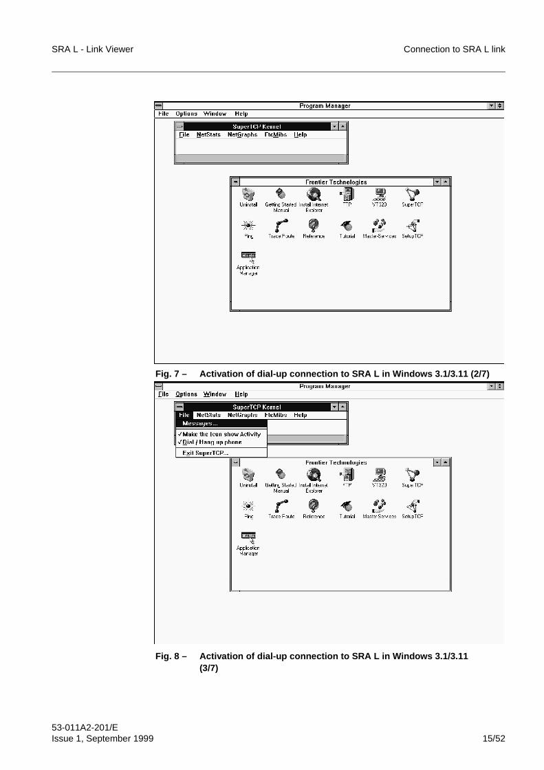
SRA L - Link Viewer Connection to SRA L link
53-011A2-201/EIssue 1, September 1999 15/52
Fig. 7 – Activation of dial-up connection to SRA L in Windows 3.1/3.11 (2/7)
Fig. 8 – Activation of dial-up connection to SRA L in Windows 3.1/3.11 (3/7)
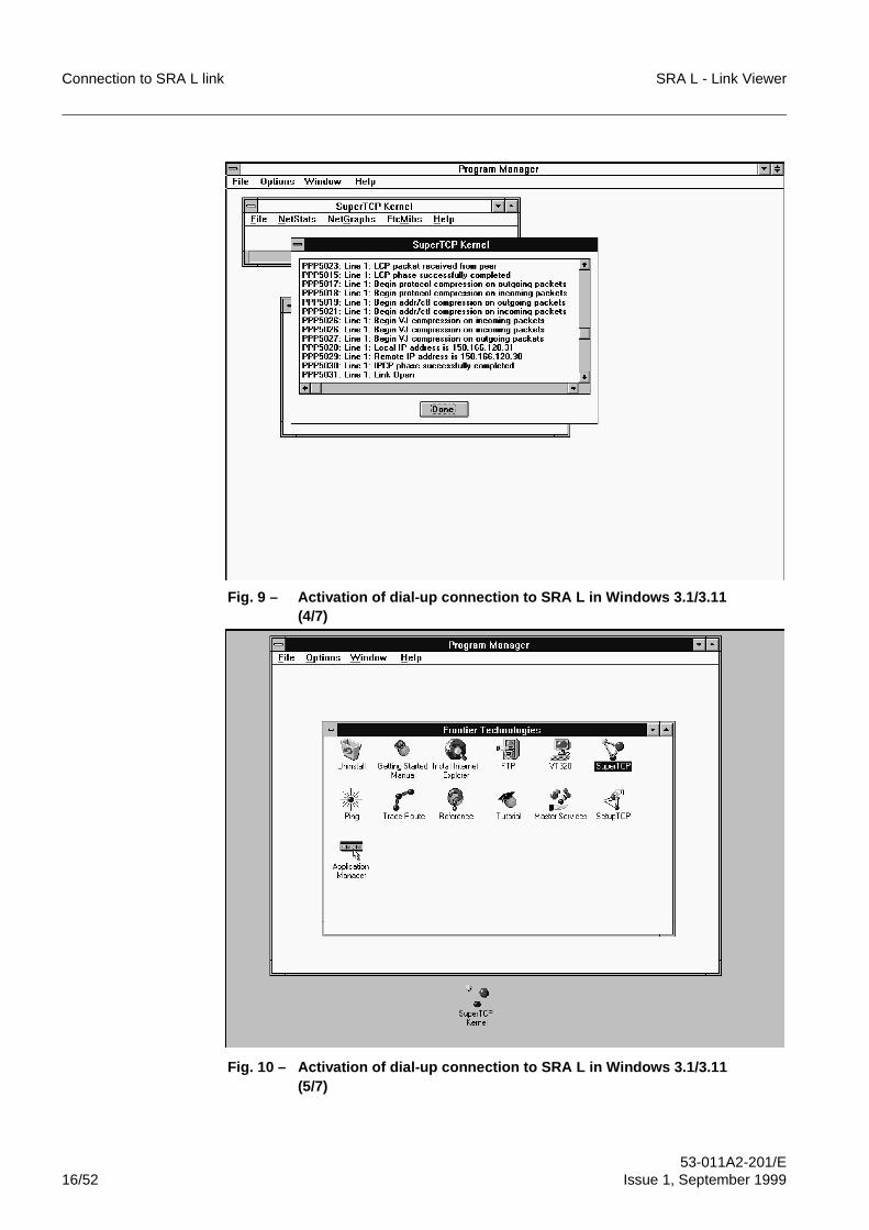
Connection to SRA L link SRA L - Link Viewer
53-011A2-201/E16/52 Issue 1, September 1999
Fig. 9 – Activation of dial-up connection to SRA L in Windows 3.1/3.11 (4/7)
Fig. 10 – Activation of dial-up connection to SRA L in Windows 3.1/3.11(5/7)
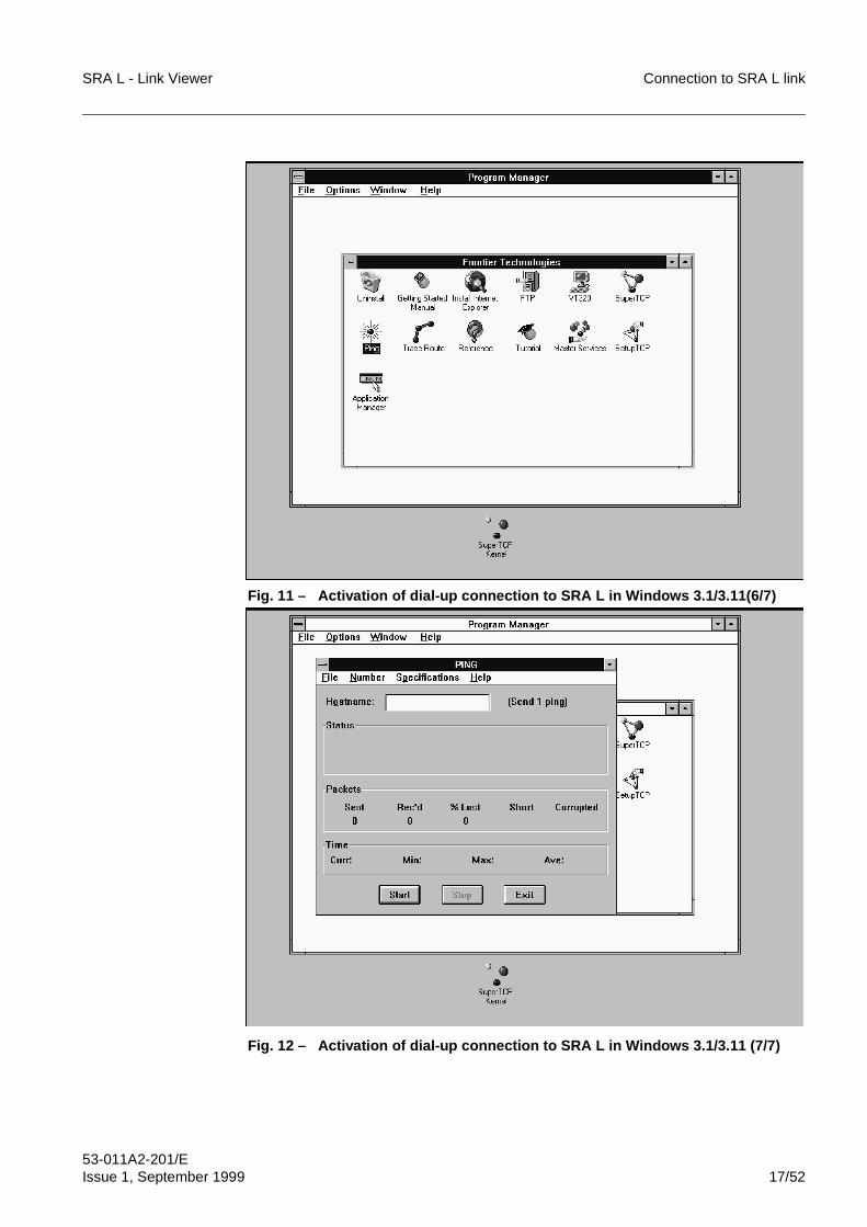
SRA L - Link Viewer Connection to SRA L link
53-011A2-201/EIssue 1, September 1999 17/52
Fig. 11 – Activation of dial-up connection to SRA L in Windows 3.1/3.11(6/7)
Fig. 12 – Activation of dial-up connection to SRA L in Windows 3.1/3.11 (7/7)
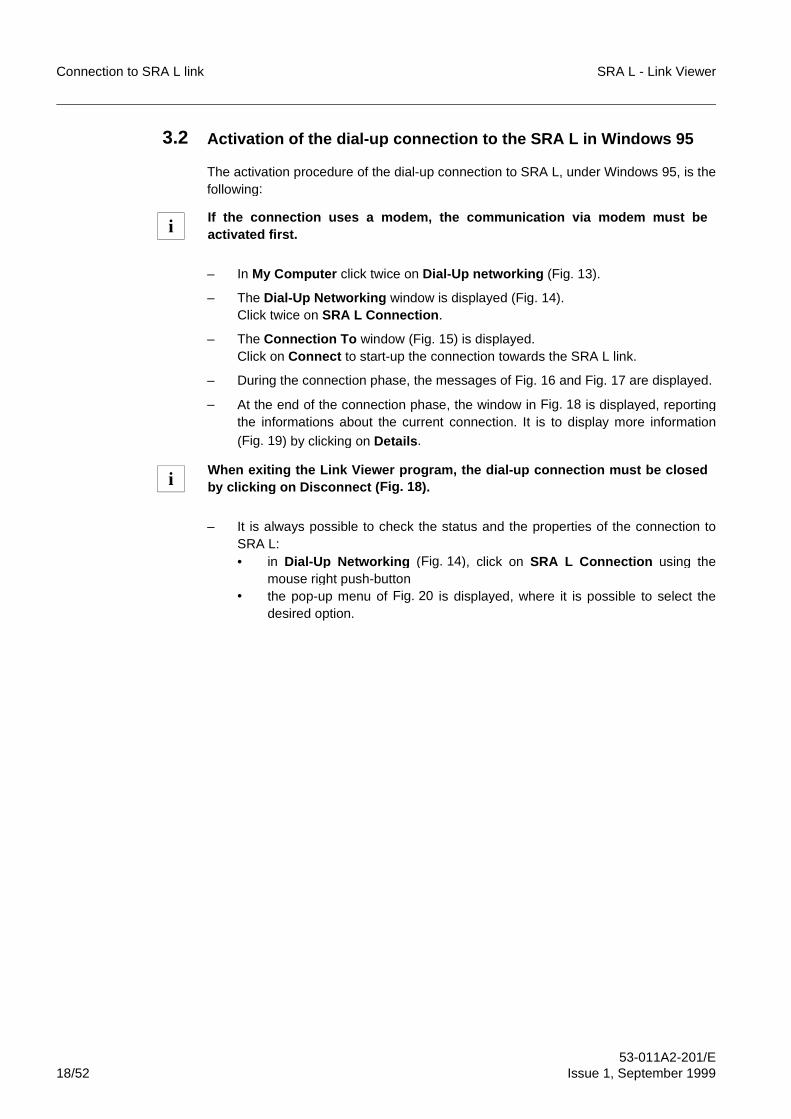
Connection to SRA L link SRA L - Link Viewer
53-011A2-201/E18/52 Issue 1, September 1999
3.2 Activation of the dial-u p connection to the SRA L in Windows 95
The activation procedure of the dial-up connection to SRA L, under Windows 95, is thefollowing:
– In My Computer click twice on Dial-Up networking (Fig. 13).
– The Dial-Up Networking window is displayed (Fig. 14).Click twice on SRA L Connection .
– The Connection To window (Fig. 15) is displayed.Click on Connect to start-up the connection towards the SRA L link.
– During the connection phase, the messages of Fig. 16 and Fig. 17 are displayed.
– At the end of the connection phase, the window in Fig. 18 is displayed, reportingthe informations about the current connection. It is to display more information
(Fig. 19) by clicking on Details .
– It is always possible to check the status and the properties of the connection toSRA L:• in Dial-Up Networkin g (Fig. 14), click on SRA L Connection using the
mouse right push-button• the pop-up menu of Fig. 20 is displayed, where it is possible to select the
desired option.
If the connection uses a modem, the communication via modem must beactivated first.
When exitin g the Link Viewer program, the dial-u p connection must be closedby clickin g on Disconnect (Fig. 18).
i
i
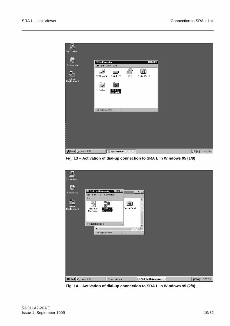
SRA L - Link Viewer Connection to SRA L link
53-011A2-201/EIssue 1, September 1999 19/52
Fig. 13 – Activation of dial-up connection to SRA L in Windows 95 (1/8)
Fig. 14 – Activation of dial-up connection to SRA L in Windows 95 (2/8)
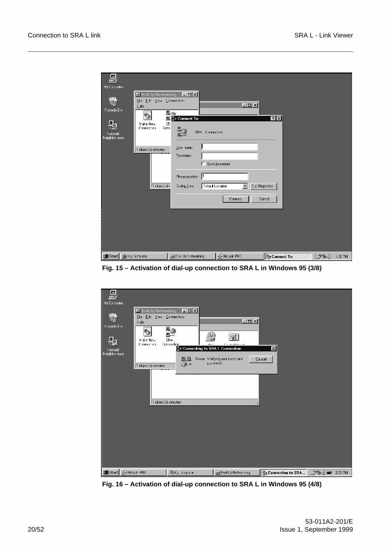
Connection to SRA L link SRA L - Link Viewer
53-011A2-201/E20/52 Issue 1, September 1999
Fig. 15 – Activation of dial-up connection to SRA L in Windows 95 (3/8)
Fig. 16 – Activation of dial-up connection to SRA L in Windows 95 (4/8)
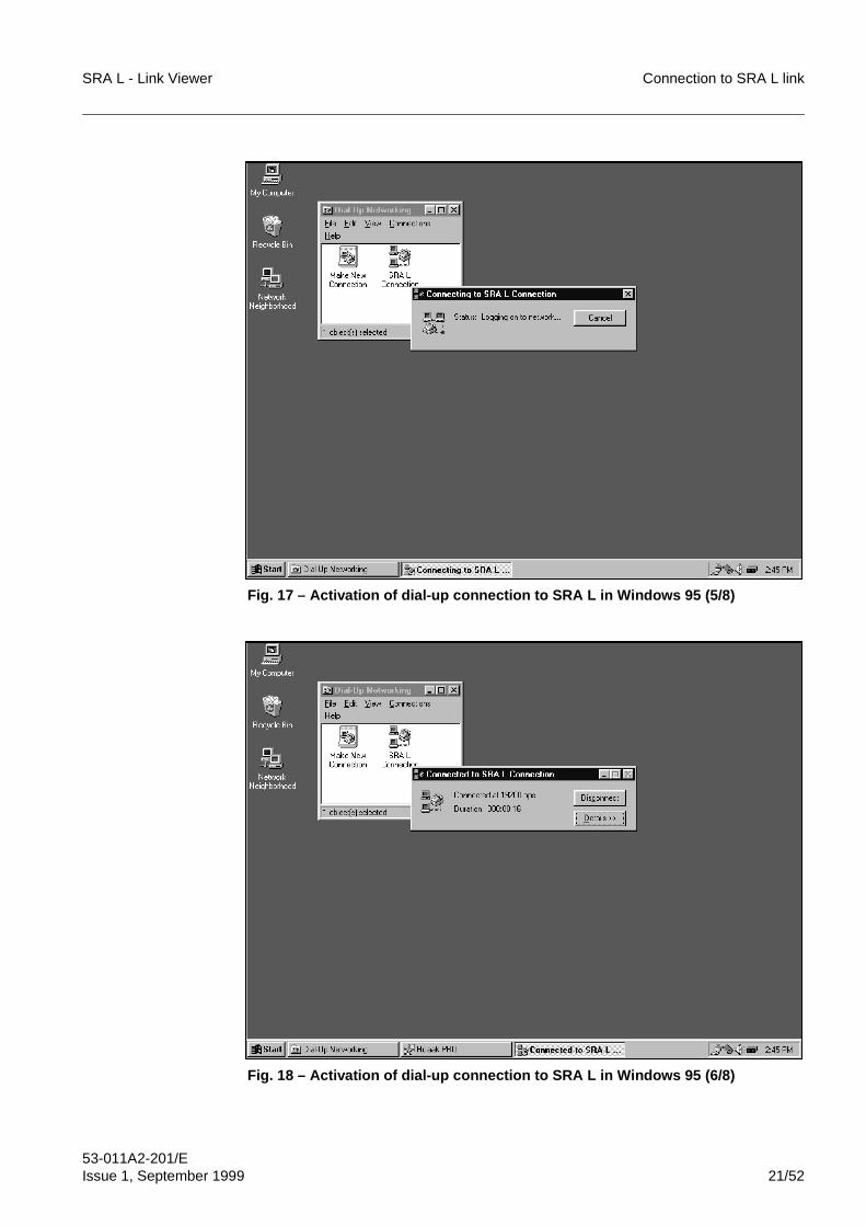
SRA L - Link Viewer Connection to SRA L link
53-011A2-201/EIssue 1, September 1999 21/52
Fig. 17 – Activation of dial-up connection to SRA L in Windows 95 (5/8)
Fig. 18 – Activation of dial-up connection to SRA L in Windows 95 (6/8)
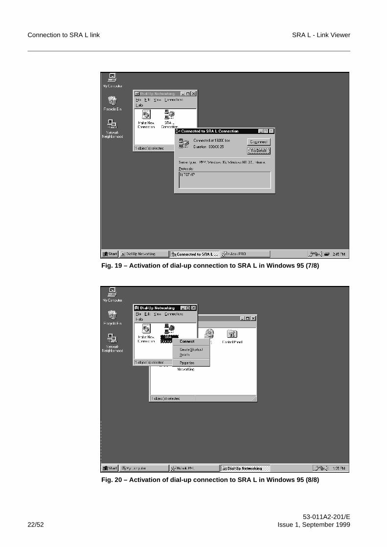
Connection to SRA L link SRA L - Link Viewer
53-011A2-201/E22/52 Issue 1, September 1999
Fig. 19 – Activation of dial-up connection to SRA L in Windows 95 (7/8)
Fig. 20 – Activation of dial-up connection to SRA L in Windows 95 (8/8)
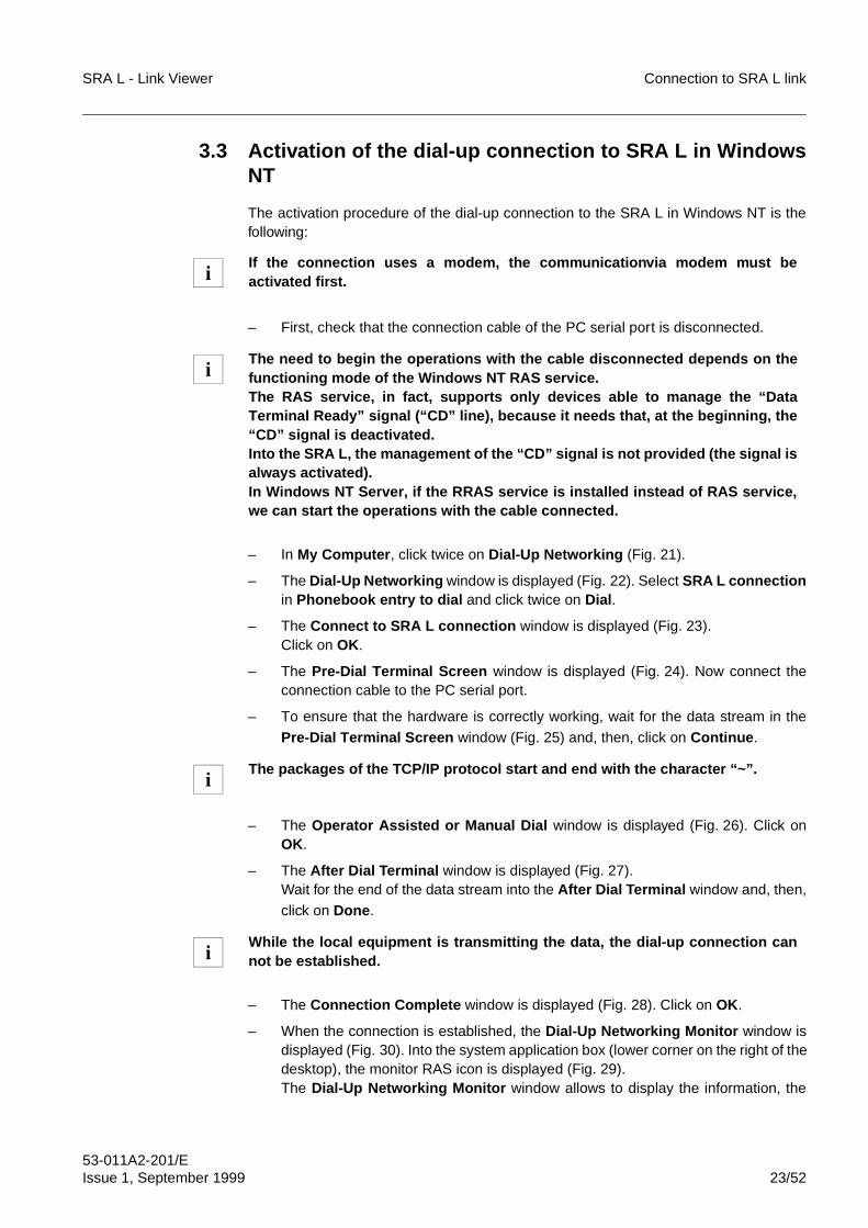
SRA L - Link Viewer Connection to SRA L link
53-011A2-201/EIssue 1, September 1999 23/52
3.3 Activation of the dial-up connection to SRA L in WindowsNT
The activation procedure of the dial-up connection to the SRA L in Windows NT is thefollowing:
– First, check that the connection cable of the PC serial port is disconnected.
– In My Computer , click twice on Dial-Up Networking (Fig. 21).
– The Dial-Up Networking window is displayed (Fig. 22). Select SRA L connectionin Phonebook entry to dial and click twice on Dial .
– The Connect to SRA L connection window is displayed (Fig. 23). Click on OK.
– The Pre-Dial Terminal Screen window is displayed (Fig. 24). Now connect theconnection cable to the PC serial port.
– To ensure that the hardware is correctly working, wait for the data stream in the
Pre-Dial Terminal Screen window (Fig. 25) and, then, click on Continue .
– The Operator Assisted or Manual Dial window is displayed (Fig. 26). Click onOK.
– The After Dial Terminal window is displayed (Fig. 27).Wait for the end of the data stream into the After Dial Terminal window and, then,
click on Done .
– The Connection Complete window is displayed (Fig. 28). Click on OK.
– When the connection is established, the Dial-Up Networking Monitor window isdisplayed (Fig. 30). Into the system application box (lower corner on the right of thedesktop), the monitor RAS icon is displayed (Fig. 29).The Dial-Up Networking Monitor window allows to display the information, the
If the connection uses a modem, the communicationvia modem must beactivated first.
The need to begin the operations with the cable disconnected depends on thefunctioning mode of the Windows NT RAS service.The RAS service, in fact, supports only devices able to manage the “DataTerminal Ready” signal (“CD” line), because it needs that, at the beginning, the“CD” signal is deactivated.Into the SRA L, the management of the “CD” signal is not provided (the signal isalways activated).In Windows NT Server, if the RRAS service is installed instead of RAS service,we can start the operations with the cable connected.
The packages of the TCP/IP protocol start and end with the character “~”.
While the local equipment is transmitting the data, the dial-up connection cannot be established.
i
i
i
i
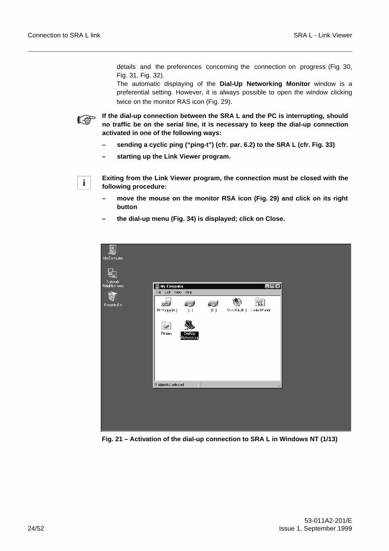
Connection to SRA L link SRA L - Link Viewer
53-011A2-201/E24/52 Issue 1, September 1999
details and the preferences concerning the connection on progress (Fig. 30,Fig. 31, Fig. 32).The automatic displaying of the Dial-Up Networking Monitor window is apreferential setting. However, it is always possible to open the window clicking
twice on the monitor RAS icon (Fig. 29).
Fig. 21 – Activation of the dial-up connection to SRA L in Windows NT (1/13)
☞ If the dial-up connection between the SRA L and the PC is interrupting, shouldno traffic be on the serial line, it is necessary to keep the dial-up connectionactivated in one of the following ways:
– sending a cyclic ping (“ping-t”) (cfr. par. 6.2) to the SRA L (cfr. Fig. 33)
– starting up the Link Viewer program.
Exiting from the Link Viewer program, the connection must be closed with thefollowing procedure:
– move the mouse on the monitor RSA icon (Fig. 29) and click on its rightbutton
– the dial-up menu (Fig. 34) is displayed; click on Close.
i
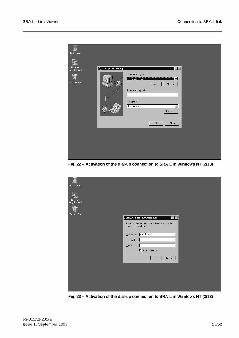
SRA L - Link Viewer Connection to SRA L link
53-011A2-201/EIssue 1, September 1999 25/52
Fig. 22 – Activation of the dial-up connection to SRA L in Windows NT (2/13)
Fig. 23 – Activation of the dial-up connection to SRA L in Windows NT (3/13)
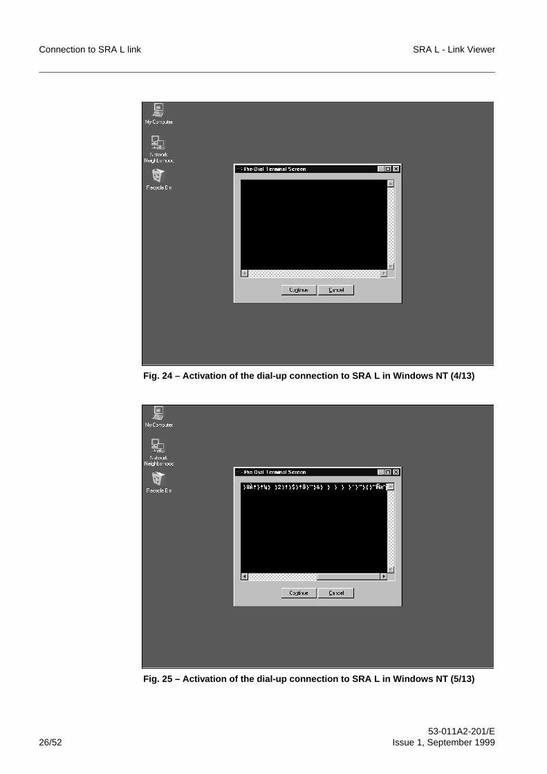
Connection to SRA L link SRA L - Link Viewer
53-011A2-201/E26/52 Issue 1, September 1999
Fig. 24 – Activation of the dial-up connection to SRA L in Windows NT (4/13)
Fig. 25 – Activation of the dial-up connection to SRA L in Windows NT (5/13)
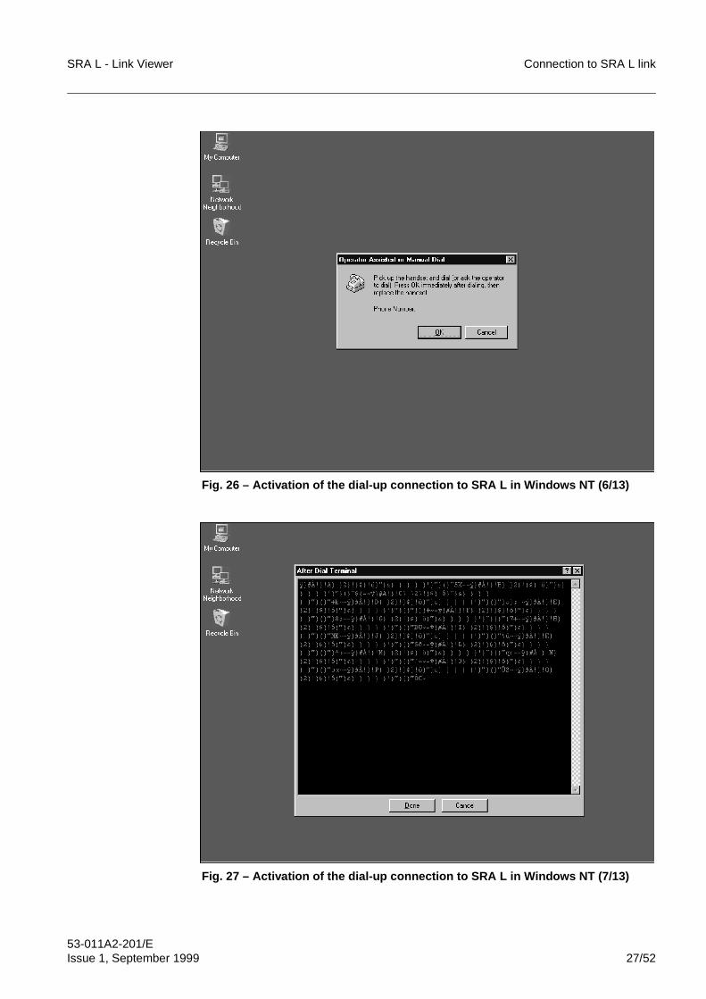
SRA L - Link Viewer Connection to SRA L link
53-011A2-201/EIssue 1, September 1999 27/52
Fig. 26 – Activation of the dial-up connection to SRA L in Windows NT (6/13)
Fig. 27 – Activation of the dial-up connection to SRA L in Windows NT (7/13)
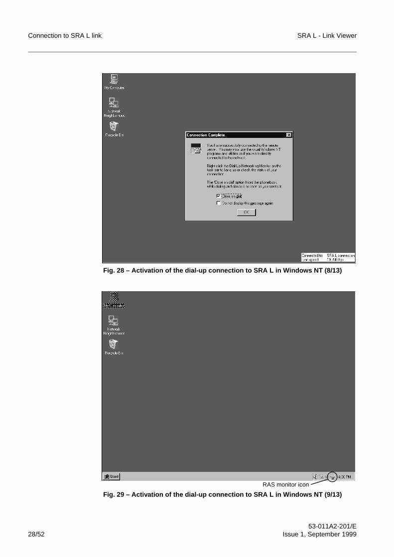
Connection to SRA L link SRA L - Link Viewer
53-011A2-201/E28/52 Issue 1, September 1999
Fig. 28 – Activation of the dial-up connection to SRA L in Windows NT (8/13)
Fig. 29 – Activation of the dial-up connection to SRA L in Windows NT (9/13)
RAS monitor icon
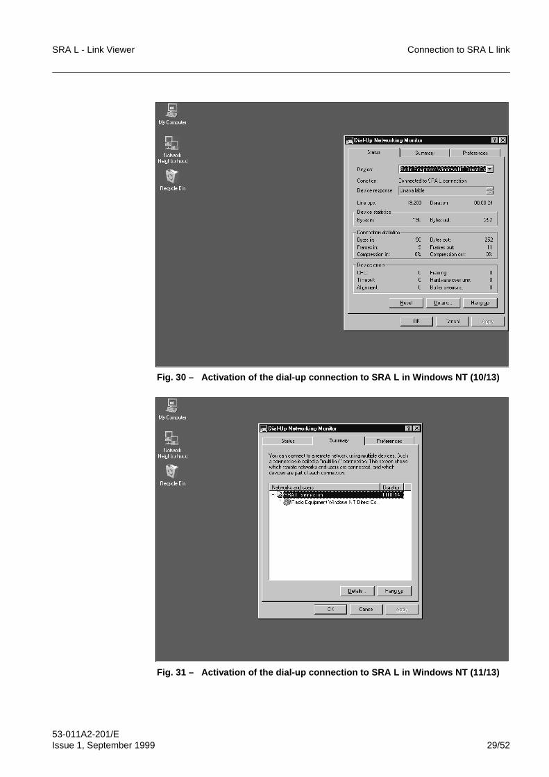
SRA L - Link Viewer Connection to SRA L link
53-011A2-201/EIssue 1, September 1999 29/52
Fig. 30 – Activation of the dial-up connection to SRA L in Windows NT (10/13)
Fig. 31 – Activation of the dial-up connection to SRA L in Windows NT (11/13)
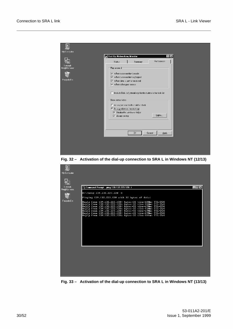
Connection to SRA L link SRA L - Link Viewer
53-011A2-201/E30/52 Issue 1, September 1999
Fig. 32 – Activation of the dial-up connection to SRA L in Windows NT (12/13)
Fig. 33 – Activation of the dial-up connection to SRA L in Windows NT (13/13)
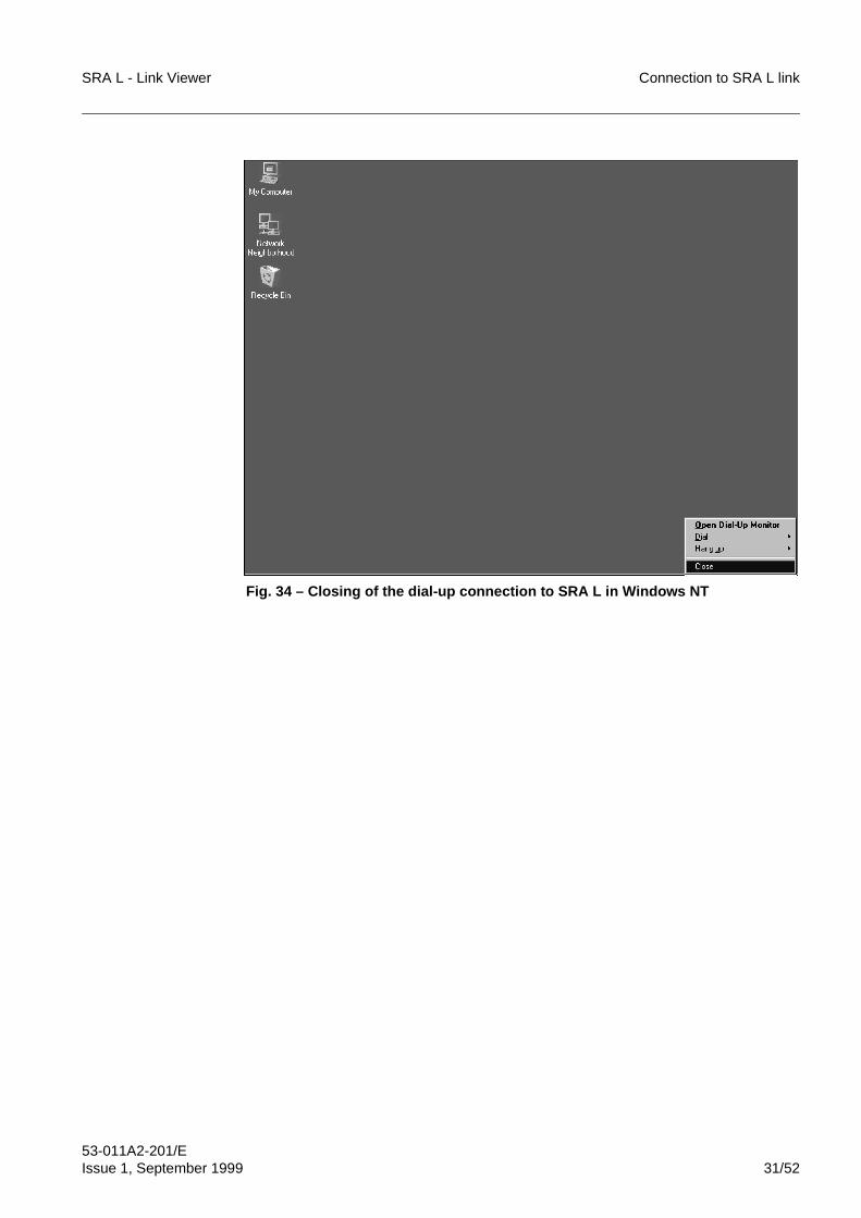
SRA L - Link Viewer Connection to SRA L link
53-011A2-201/EIssue 1, September 1999 31/52
Fig. 34 – Closing of the dial-up connection to SRA L in Windows NT
Connection to SRA L link SRA L - Link Viewer
53-011A2-201/E32/52 Issue 1, September 1999
4 LOADING OF SRA L CONFIGURATION FILEIn Link Viewer program, we must load the SRA L configuration file to activate itsmanagement and control operative functions, that is to access the SRA L.To load the configuration file, we must open the map containing the relative SRA L and,then, activate the access towards the SRA L.
4.1 Map opening
The map is the graphic interface for accessing the SRA L in Link Viewer program. If themap Security is enabled, the system requires to insert the user class and the relativepassword (see Fig. 35) at map opening.At map opening, Link Viewer tries to connect to every enabled SRA L; for every SRA L,the connection phase takes places in the following way:
– should a communication error be detected (non-existent equipment, for instance),an icon is displayed, indicating that the SRA L is disconnected (involuntarydisabled status)
– should the connection be successful, the program tries to identify the SRA L:• if the identification is successful, a predefined icon is displayed, indicating the
SRA L type (see Fig. 36); furthermore, the equipment menu is added• if the identification is not successful (the plug-in for this kind of SRA L is not
installed, for instance), a icon is displayed, indicating that this SRA L type is
not supported.
The program cyclically makes an attempt for an automatic connection towards the SRALs which are in involuntary disabled status.The program carries out a periodic polling to monitor the connection and alarm status(severity) of every SRA L. The possible values of severity for a SRA L are the following:
– disconnected
– normal
– test
– warning
– minor
– major
– critical.
A specific icon signals the involuntary disabled status for the SRA L.
If all the following conditions are present, some connection troubles could occurusing the local map (default local IP address = 192.168.255.3):• dial-up connection by RS-232C serial interface• TCP/IP protocol used also by other interfaces (e.g.: Ethernet for local
network, etc.)• local equipment with IP address correctly configured.In this case, it is necessary to create a new map with the effective IP address (seepar. 6) of the equipment, because the local map can not be used.
i
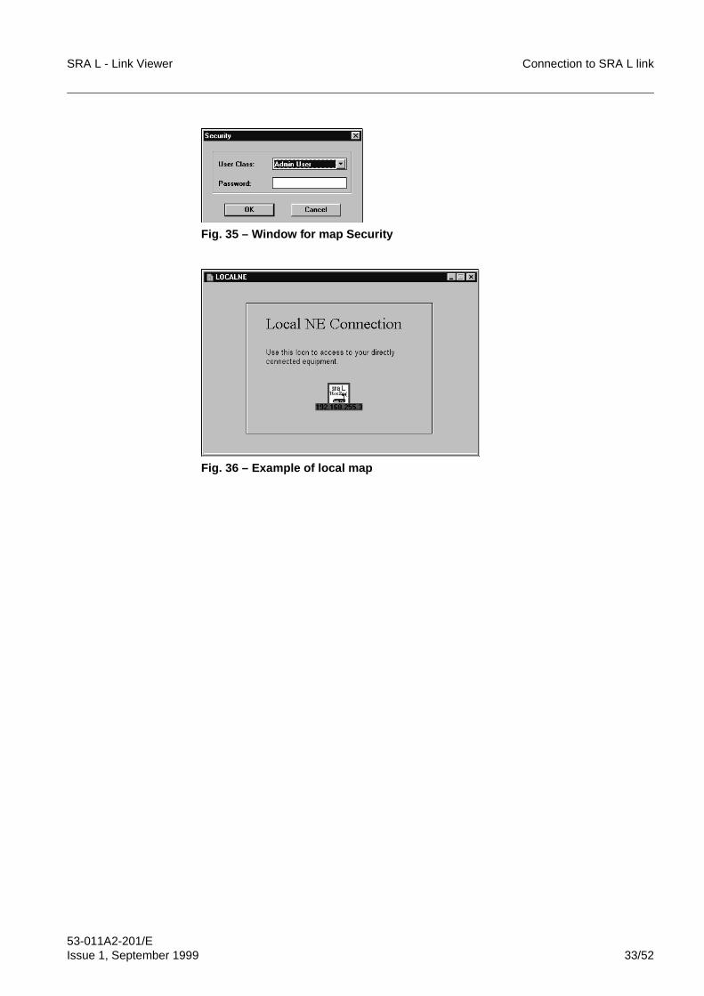
SRA L - Link Viewer Connection to SRA L link
53-011A2-201/EIssue 1, September 1999 33/52
Fig. 35 – Window for map Security
Fig. 36 – Example of local map
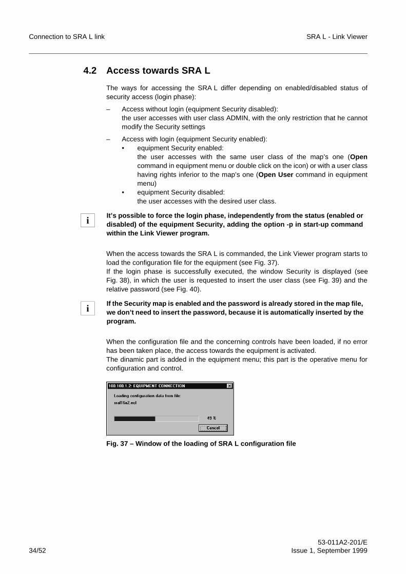
Connection to SRA L link SRA L - Link Viewer
53-011A2-201/E34/52 Issue 1, September 1999
4.2 Access towards SRA L
The ways for accessing the SRA L differ depending on enabled/disabled status ofsecurity access (login phase):
– Access without login (equipment Security disabled):the user accesses with user class ADMIN, with the only restriction that he cannotmodify the Security settings
– Access with login (equipment Security enabled):• equipment Security enabled:
the user accesses with the same user class of the map’s one (Opencommand in equipment menu or double click on the icon) or with a user classhaving rights inferior to the map’s one (Open User command in equipmentmenu)
• equipment Security disabled:the user accesses with the desired user class.
When the access towards the SRA L is commanded, the Link Viewer program starts toload the configuration file for the equipment (see Fig. 37).If the login phase is successfully executed, the window Security is displayed (seeFig. 38), in which the user is requested to insert the user class (see Fig. 39) and therelative password (see Fig. 40).
When the configuration file and the concerning controls have been loaded, if no errorhas been taken place, the access towards the equipment is activated.The dinamic part is added in the equipment menu; this part is the operative menu forconfiguration and control.
Fig. 37 – Window of the loading of SRA L configuration file
It’s possible to force the login phase, independently from the status (enabled ordisabled) of the equipment Security, adding the option -p in start-up commandwithin the Link Viewer program.
If the Security map is enabled and the password is already stored in the map file,we don’t need to insert the password, because it is automatically inserted by theprogram.
i
i
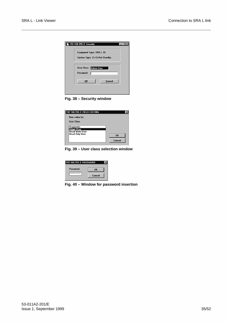
SRA L - Link Viewer Connection to SRA L link
53-011A2-201/EIssue 1, September 1999 35/52
Fig. 38 – Security window
Fig. 39 – User class selection window
Fig. 40 – Window for password insertion
Connection to SRA L link SRA L - Link Viewer
53-011A2-201/E36/52 Issue 1, September 1999
5 ROUTING TROUBLES WITH THE TCP/IP PACKETS IN
WINDOWS 95/NT
5.1 Common cases of TCP/IP packet routing
The TCP/IP protocol can manage different interfaces (serial line, Ethernet network, etc.)according to the network functions present on the service PC (PC - equipmentconnection, Internet connection, company LAN connection, etc.).Then, some routing troubles with the TCP/IP packets can occur.The most common cases are the following ones:
– TCP/IP on serial line only If on the service PC the TCP/IP protocol manages only the serial line and it hasbeen correctly configured, all the sent packets are forwarded on the serial line.In this case, if the equipment is directly connected to the service PC, it is alwaysreachable.In case of troubles, it is possible to force the packet forwarding on the serial lineselecting the option “Use default gateway on remote network” into the configurationwindow of the TCP/IP protocol for the serial line (Fig. 41 and Fig. 42).
– TCP/IP on Ethernet network only If on the service PC the TCP/IP protocol manages only the Ethernet network andit has been correctly configured, all the sent packets are forwarded on the Ethernetnetwork.In this case to reach the equipment, it is necessary to configure correctly theinvolved gateways.
– TCP/IP as on serial line as on Ethernet network If on the service PC the TCP/IP protocol manages as the serial line as the Ethernetnetwork, for each sent packet the system has to decide the use of the serial line orof the Ethernet network. In each case, it will be used only one of the two routes.The choice of the route to be used depends on the IP address of the target, on theconfiguration of the TCP/IP protocol and on the equipment connected to the serialline.If on the serial line, it is connected an equipment with IP address X.X.X.X, therelevant serial port of the service PC will have an IP address equal to the one ofthe equipment plus 1 and a Net-Mask that depends on the class of its own IPaddress (on the contrary, it does not depend on the equipment Net-Mask). TheEthernet card of the service PC has an IP address and a Net-Mask presetted bythe user.A packet with IP address X.X.X.X is forwarded:• on the serial line, if it belongs to the sub-network defined by the IP addess and
by the Net-Mask of the service PC serial port (For instance: in the case ofserial port with IP address = 150.160.170.181 and Net-Mask = 255.255.0.0,the addresses that belong to the sub-network are 150.160.X.X)
• on the Ethernet network, if it belongs to the sub-network defined by the IPaddess and by the Net-Mask of the service PC network card (for instance: inthe case of Ethernet card with IP address = 138.132.140.104 and Net-Mask= 255.255.255.0, the addresses that belong to the sub-network are138.132.140.X).
To route correctly some packets with an IP address not compatible neither with the
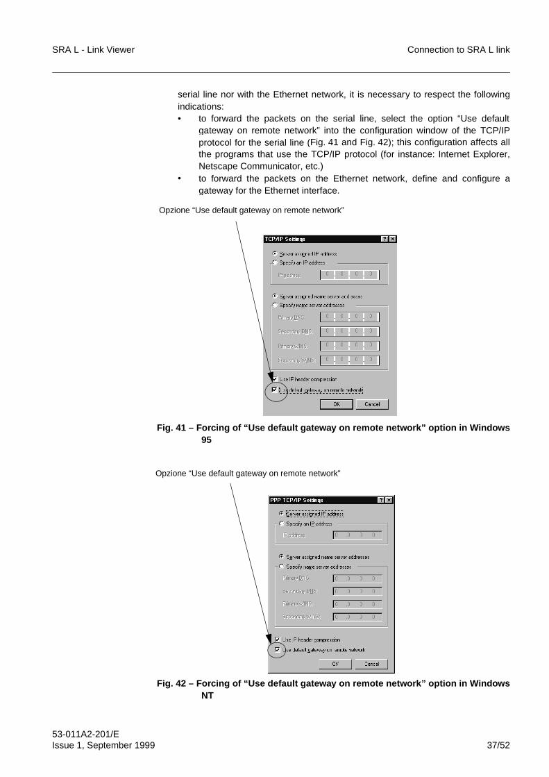
SRA L - Link Viewer Connection to SRA L link
53-011A2-201/EIssue 1, September 1999 37/52
serial line nor with the Ethernet network, it is necessary to respect the followingindications:• to forward the packets on the serial line, select the option “Use default
gateway on remote network” into the configuration window of the TCP/IPprotocol for the serial line (Fig. 41 and Fig. 42); this configuration affects allthe programs that use the TCP/IP protocol (for instance: Internet Explorer,Netscape Communicator, etc.)
• to forward the packets on the Ethernet network, define and configure agateway for the Ethernet interface.
Fig. 41 – Forcing of “Use default gateway on remote network” option in Windows95
Fig. 42 – Forcing of “Use default gateway on remote network” option in WindowsNT
Opzione “Use default gateway on remote network”
Opzione “Use default gateway on remote network”
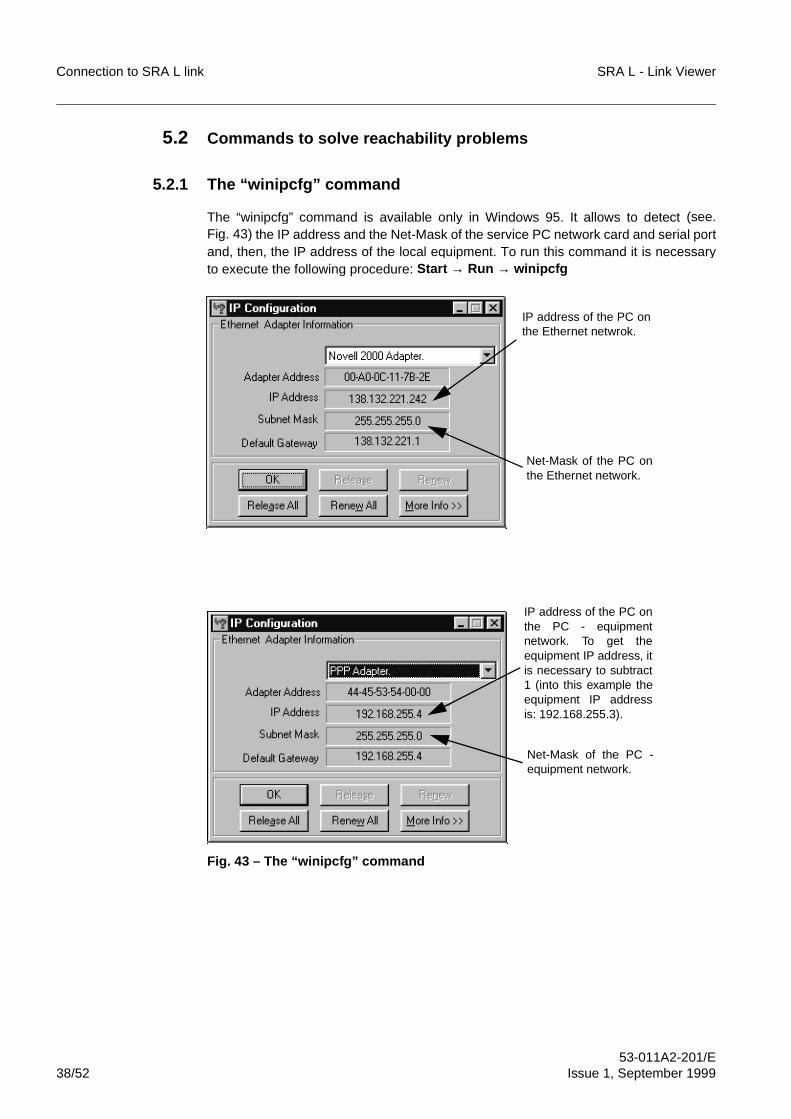
Connection to SRA L link SRA L - Link Viewer
53-011A2-201/E38/52 Issue 1, September 1999
5.2 Commands to solve reachability problems
5.2.1 The “winipcfg” command
The “winipcfg” command is available only in Windows 95. It allows to detect (see.Fig. 43) the IP address and the Net-Mask of the service PC network card and serial portand, then, the IP address of the local equipment. To run this command it is necessaryto execute the following procedure: Start → Run → winipcfg
Fig. 43 – The “winipcfg” command
Net-Mask of the PC onthe Ethernet network.
IP address of the PC onthe Ethernet netwrok.
Net-Mask of the PC -equipment network.
IP address of the PC onthe PC - equipmentnetwork. To get theequipment IP address, itis necessary to subtract1 (into this example theequipment IP addressis: 192.168.255.3).
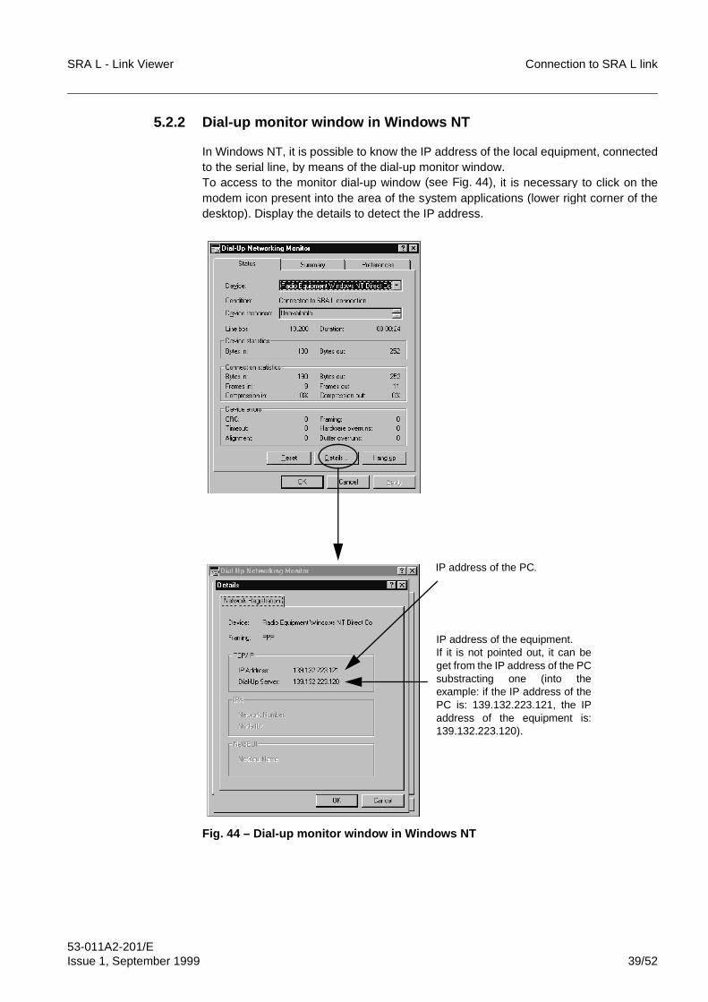
SRA L - Link Viewer Connection to SRA L link
53-011A2-201/EIssue 1, September 1999 39/52
5.2.2 Dial-up monitor window in Windows NT
In Windows NT, it is possible to know the IP address of the local equipment, connectedto the serial line, by means of the dial-up monitor window.To access to the monitor dial-up window (see Fig. 44), it is necessary to click on themodem icon present into the area of the system applications (lower right corner of thedesktop). Display the details to detect the IP address.
Fig. 44 – Dial-up monitor window in Windows NT
IP address of the PC.
IP address of the equipment.If it is not pointed out, it can beget from the IP address of the PCsubstracting one (into theexample: if the IP address of thePC is: 139.132.223.121, the IPaddress of the equipment is:139.132.223.120).
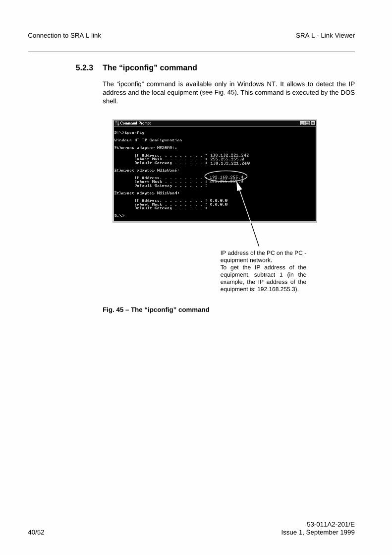
Connection to SRA L link SRA L - Link Viewer
53-011A2-201/E40/52 Issue 1, September 1999
5.2.3 The “ipconfig” command
The “ipconfig” command is available only in Windows NT. It allows to detect the IPaddress and the local equipment (see Fig. 45). This command is executed by the DOSshell.
Fig. 45 – The “ipconfig” command
IP address of the PC on the PC -equipment network.To get the IP address of theequipment, subtract 1 (in theexample, the IP address of theequipment is: 192.168.255.3).
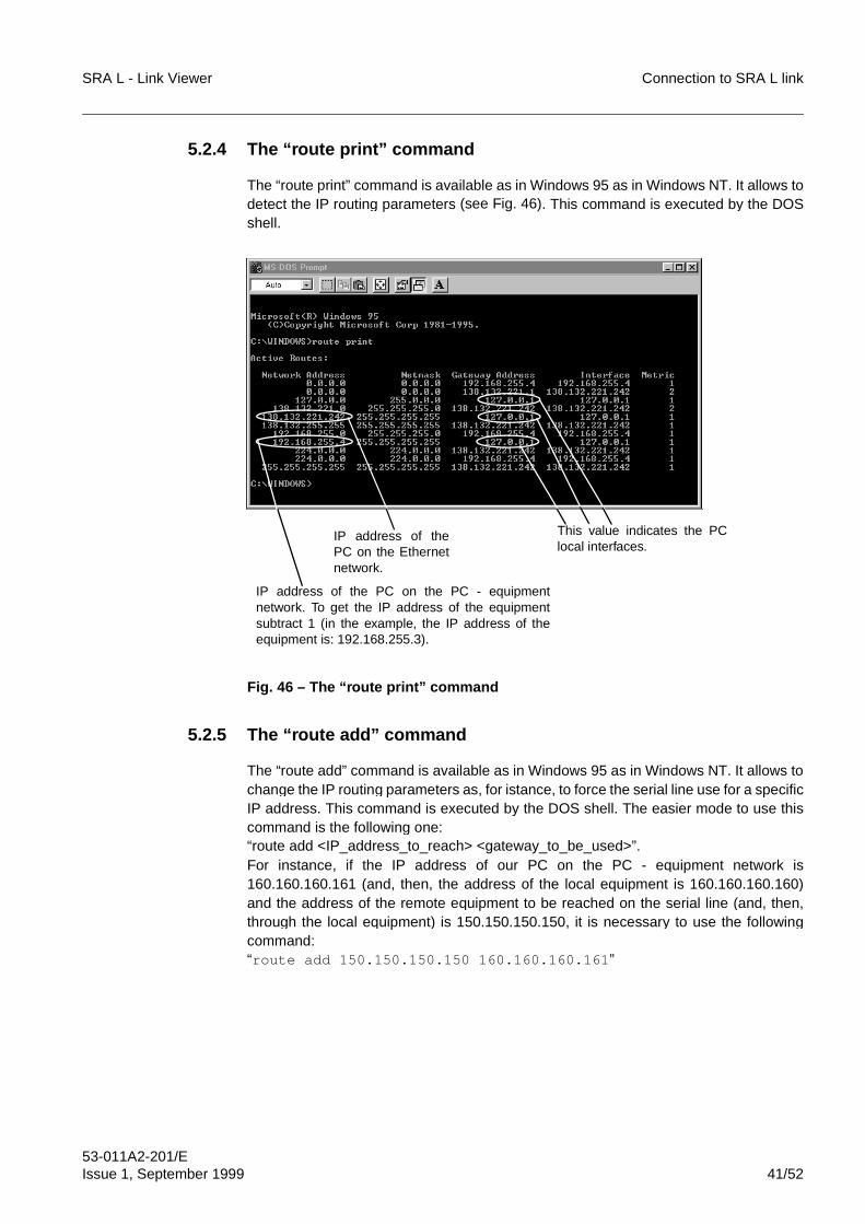
SRA L - Link Viewer Connection to SRA L link
53-011A2-201/EIssue 1, September 1999 41/52
5.2.4 The “route print” command
The “route print” command is available as in Windows 95 as in Windows NT. It allows todetect the IP routing parameters (see Fig. 46). This command is executed by the DOSshell.
Fig. 46 – The “route print” command
5.2.5 The “route add” command
The “route add” command is available as in Windows 95 as in Windows NT. It allows tochange the IP routing parameters as, for istance, to force the serial line use for a specificIP address. This command is executed by the DOS shell. The easier mode to use thiscommand is the following one:“route add <IP_address_to_reach> <gateway_to_be_used>”.For instance, if the IP address of our PC on the PC - equipment network is160.160.160.161 (and, then, the address of the local equipment is 160.160.160.160)and the address of the remote equipment to be reached on the serial line (and, then,through the local equipment) is 150.150.150.150, it is necessary to use the followingcommand:“route add 150.150.150.150 160.160.160.161 ”
This value indicates the PClocal interfaces.
IP address of thePC on the Ethernetnetwork.
IP address of the PC on the PC - equipmentnetwork. To get the IP address of the equipmentsubtract 1 (in the example, the IP address of theequipment is: 192.168.255.3).
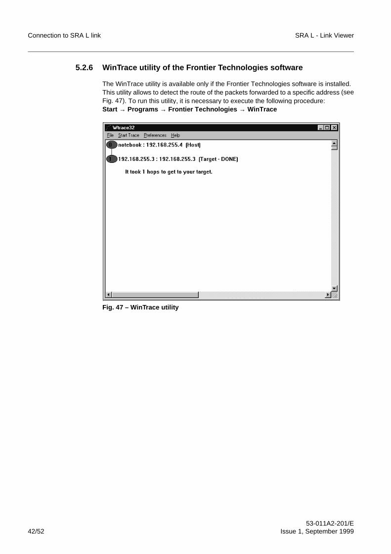
Connection to SRA L link SRA L - Link Viewer
53-011A2-201/E42/52 Issue 1, September 1999
5.2.6 WinTrace utility of the Frontier Technologies software
The WinTrace utility is available only if the Frontier Technologies software is installed.This utility allows to detect the route of the packets forwarded to a specific address (seeFig. 47). To run this utility, it is necessary to execute the following procedure:Start → Programs → Frontier Technologies → WinTrace
Fig. 47 – WinTrace utility

SRA L - Link Viewer Connection to SRA L link
53-011A2-201/EIssue 1, September 1999 43/52
5.2.7 The “tracert” command
The “tracert” command is available as in Windows 95 as in Windows NT. It allows todetect the route of the packets forwarded to a specific address (see Fig. 48). Thiscommand is executed by the DOS shell. It is necessary to specify the destination IPaddress: “tracert IP_address”.
Fig. 48 – The “tracert” command
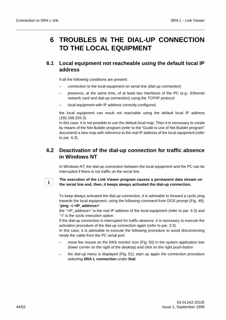
Connection to SRA L link SRA L - Link Viewer
53-011A2-201/E44/52 Issue 1, September 1999
6 TROUBLES IN THE DIAL-UP CONNECTIONTO THE LOCAL EQUIPMENT
6.1 Local equipment not reacheable using the default local IPaddress
If all the following conditions are present:
– connection to the local equipment on serial line (dial-up connection)
– presence, at the same time, of at least two interfaces of the PC (e.g.: Ethernetnetwork card and dial-up connection) using the TCP/IP protocol
– local equipment with IP address correctly configured,
the local equipment can result not reachable using the default local IP address(192.168.255.3).In this case, it is not possible to use the default local map. Then it is necessary to createby means of the Net Builder program (refer to the “Guide to use of Net Builder program”document) a new map with reference to the real IP address of the local equipment (referto par. 6.3).
6.2 Deactivation of the dial-up connection for traffic absencein Windows NT
In Windows NT, the dial-up connection between the local equipment and the PC can beinterrupted if there is not traffic on the serial line.
To keep always activated the dial-up connection, it is advisable to forward a cyclic pingtowards the local equipment, using the following command from DOS prompt (Fig. 49):“ping –t <IP_address> ”the “<IP_address>” is the real IP address of the local equipment (refer to par. 6.3) and“-t” is the cyclic execution option.If the dial-up connection is interrupted for traffic absence, it is necessary to execute theactivation procedure of the dial-up connection again (refer to par. 3.3).In this case, it is advisable to execute the following procedure to avoid disconnectingnewly the cable from the PC serial port:
– move the mouse on the RAS monitor icon (Fig. 50) in the system application box(lower corner on the right of the desktop) and click on the right push-button
– the dial-up menu is displayed (Fig. 51); start up again the connection procedureselecting SRA L connection under Dial .
The execution of the Link Viewer program causes a permanent data stream onthe serial line and, then, it keeps always activated the dial-up connection.i
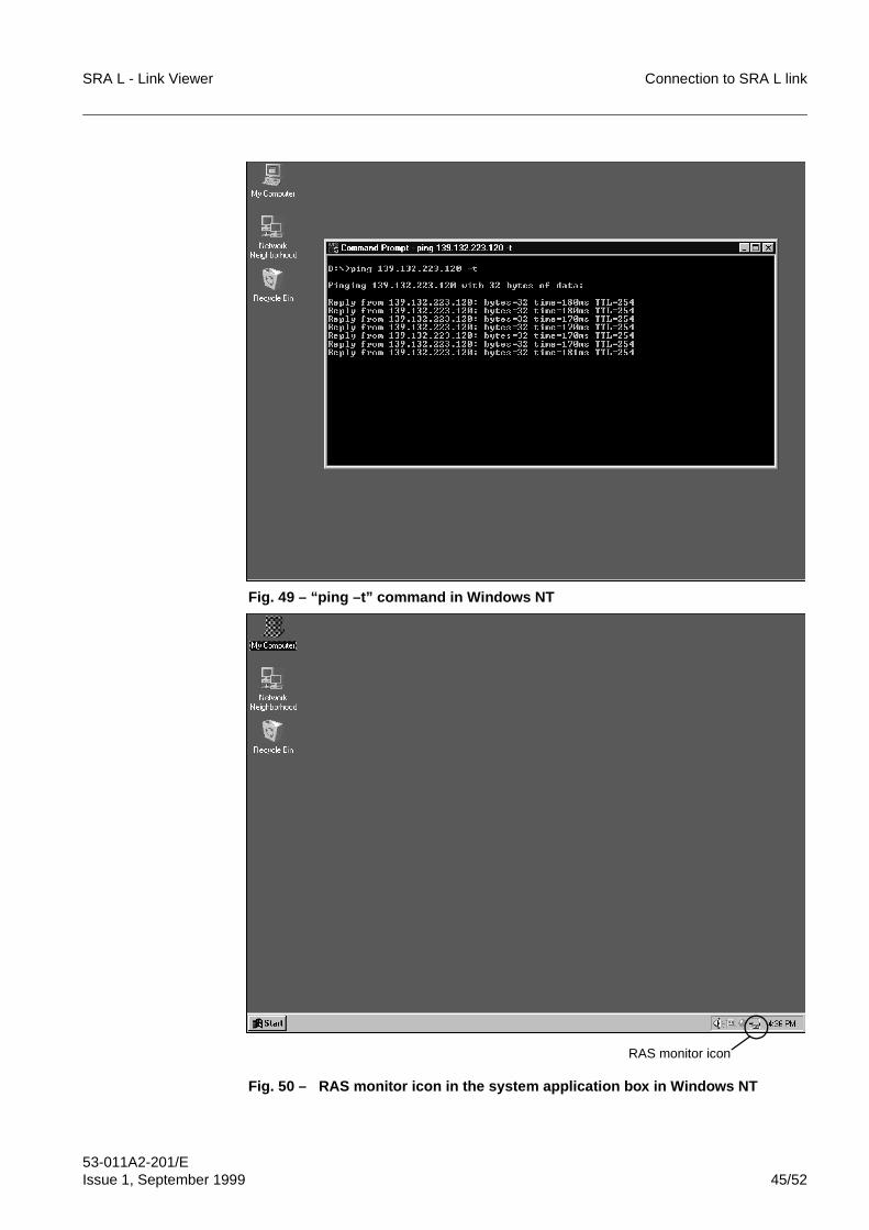
SRA L - Link Viewer Connection to SRA L link
53-011A2-201/EIssue 1, September 1999 45/52
Fig. 49 – “ping –t” command in Windows NT
Fig. 50 – RAS monitor icon in the system application box in Windows NT
RAS monitor icon
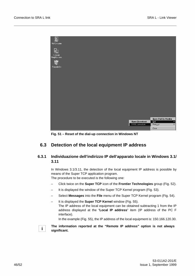
Connection to SRA L link SRA L - Link Viewer
53-011A2-201/E46/52 Issue 1, September 1999
Fig. 51 – Reset of the dial-up connection in Windows NT
6.3 Detection of the local equipment IP address
6.3.1 Individuazione dell’indirizzo IP dell’apparato locale in Windows 3.1/3.11
In Windows 3.1/3.11, the detection of the local equipment IP address is possible bymeans of the Super TCP application program.The procedure to be executed is the following one:
– Click twice on the Super TCP icon of the Frontier Technologies group (Fig. 52).
– It is displayed the window of the Super TCP Kernel program (Fig. 53).
– Select Messages into the File menu of the Super TCP Kernel program (Fig. 54).
– It is displayed the Super TCP Kernel window (Fig. 55).The IP address of the local equipment can be obtained subtracting 1 from the IPaddress displayed at the “Local IP address ” item (IP address of the PC Finterface).In the example (Fig. 55), the IP address of the local equipment is: 150.166.120.30.
The information reported at the “Remote IP address” option is not alwayssignificant.i
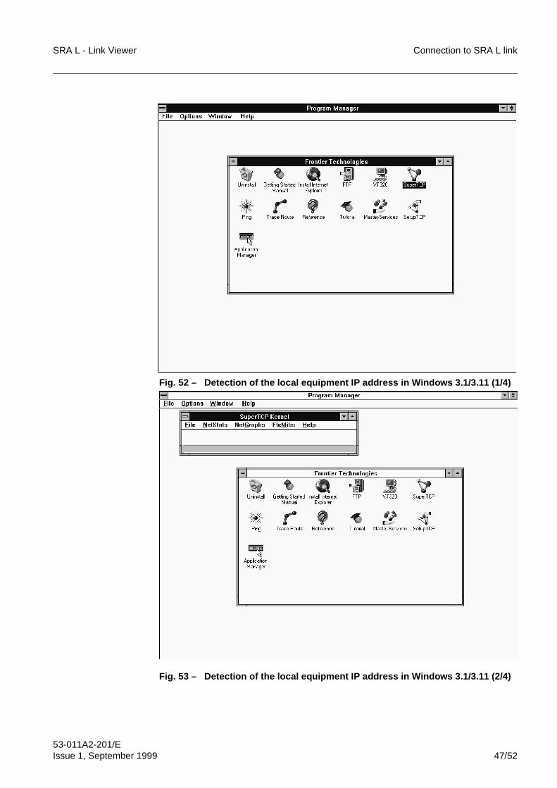
SRA L - Link Viewer Connection to SRA L link
53-011A2-201/EIssue 1, September 1999 47/52
Fig. 52 – Detection of the local equipment IP address in Windows 3.1/3.11 (1/4)
Fig. 53 – Detection of the local equipment IP address in Windows 3.1/3.11 (2/4)
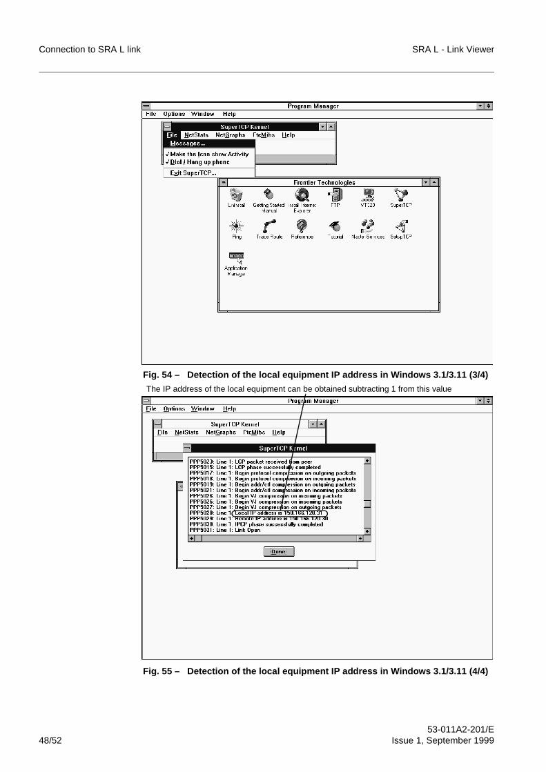
Connection to SRA L link SRA L - Link Viewer
53-011A2-201/E48/52 Issue 1, September 1999
Fig. 54 – Detection of the local equipment IP address in Windows 3.1/3.11 (3/4)
Fig. 55 – Detection of the local equipment IP address in Windows 3.1/3.11 (4/4)
The IP address of the local equipment can be obtained subtracting 1 from this value
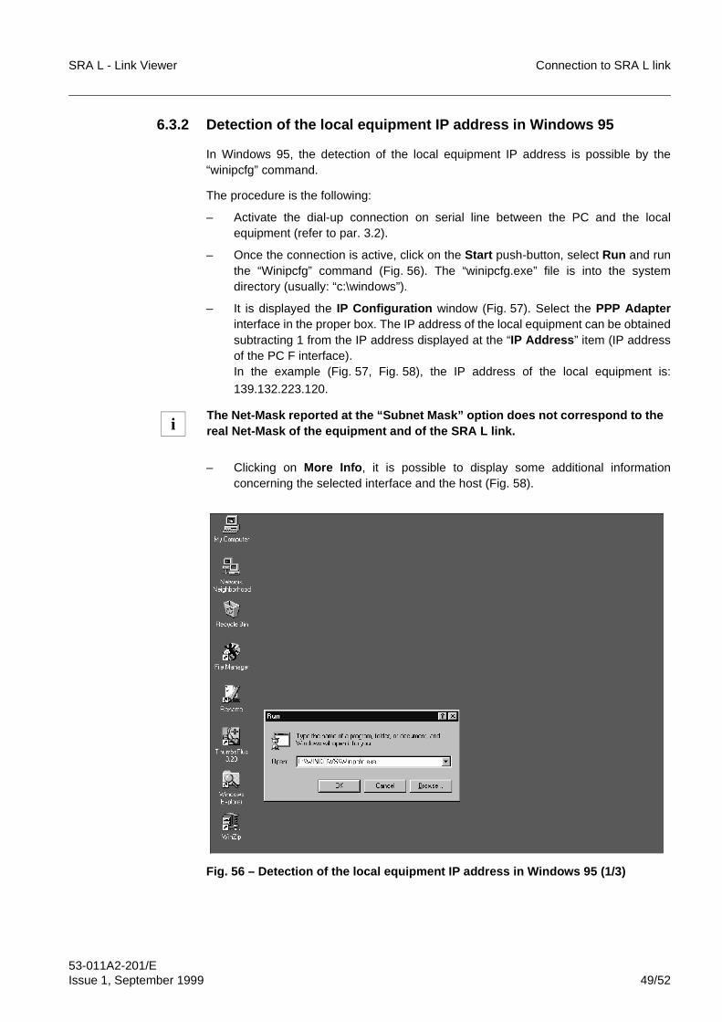
SRA L - Link Viewer Connection to SRA L link
53-011A2-201/EIssue 1, September 1999 49/52
6.3.2 Detection of the local equipment IP address in Windows 95
In Windows 95, the detection of the local equipment IP address is possible by the“winipcfg” command.
The procedure is the following:
– Activate the dial-up connection on serial line between the PC and the localequipment (refer to par. 3.2).
– Once the connection is active, click on the Start push-button, select Run and runthe “Winipcfg” command (Fig. 56). The “winipcfg.exe” file is into the systemdirectory (usually: “c:\windows”).
– It is displayed the IP Configuration window (Fig. 57). Select the PPP Adapterinterface in the proper box. The IP address of the local equipment can be obtainedsubtracting 1 from the IP address displayed at the “IP Address ” item (IP addressof the PC F interface).In the example (Fig. 57, Fig. 58), the IP address of the local equipment is:
139.132.223.120.
– Clicking on More Info , it is possible to display some additional informationconcerning the selected interface and the host (Fig. 58).
Fig. 56 – Detection of the local equipment IP address in Windows 95 (1/3)
The Net-Mask reported at the “Subnet Mask” option does not correspond to thereal Net-Mask of the equipment and of the SRA L link.i
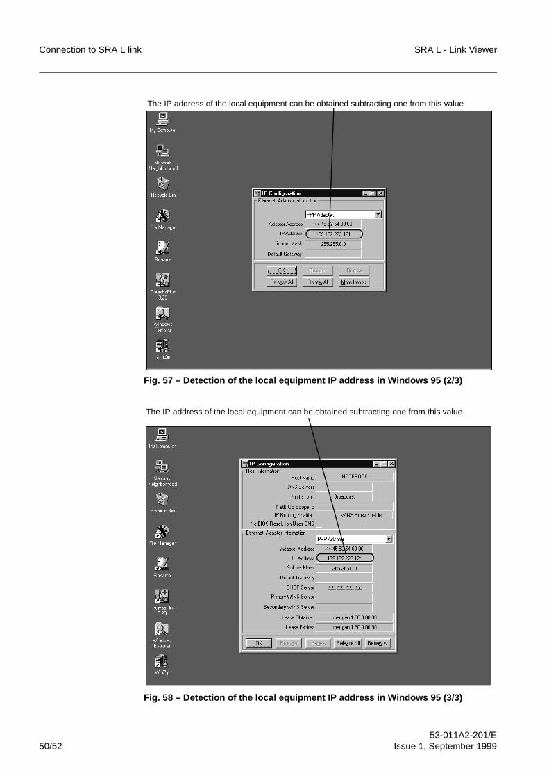
Connection to SRA L link SRA L - Link Viewer
53-011A2-201/E50/52 Issue 1, September 1999
Fig. 57 – Detection of the local equipment IP address in Windows 95 (2/3)
Fig. 58 – Detection of the local equipment IP address in Windows 95 (3/3)
The IP address of the local equipment can be obtained subtracting one from this value
The IP address of the local equipment can be obtained subtracting one from this value
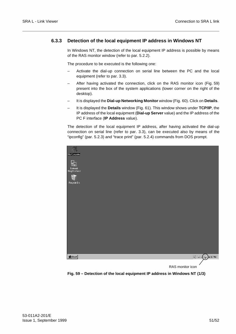
SRA L - Link Viewer Connection to SRA L link
53-011A2-201/EIssue 1, September 1999 51/52
6.3.3 Detection of the local equipment IP address in Windows NT
In Windows NT, the detection of the local equipment IP address is possible by meansof the RAS monitor window (refer to par. 5.2.2).
The procedure to be executed is the following one:
– Activate the dial-up connection on serial line between the PC and the localequipment (refer to par. 3.3).
– After having activated the connection, click on the RAS monitor icon (Fig. 59)present into the box of the system applications (lower corner on the right of thedesktop).
– It is displayed the Dial-up Networking Monitor window (Fig. 60). Click on Details .
– It is displayed the Details window (Fig. 61). This window shows under TCP/IP, theIP address of the local equipment (Dial-up Server value) and the IP address of thePC F interface (IP Address value).
The detection of the local equipment IP address, after having activated the dial-upconnection on serial line (refer to par. 3.3), can be executed also by means of the“ipconfig” (par. 5.2.3) and “trace print” (par. 5.2.4) commands from DOS prompt.
Fig. 59 – Detection of the local equipment IP address in Windows NT (1/3)
RAS monitor icon
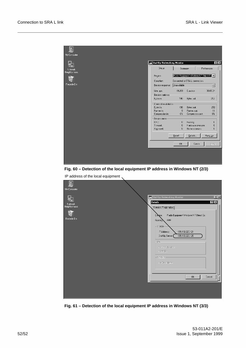
Connection to SRA L link SRA L - Link Viewer
53-011A2-201/E52/52 Issue 1, September 1999
FINE
Fig. 60 – Detection of the local equipment IP address in Windows NT (2/3)
Fig. 61 – Detection of the local equipment IP address in Windows NT (3/3)
IP address of the local equipment
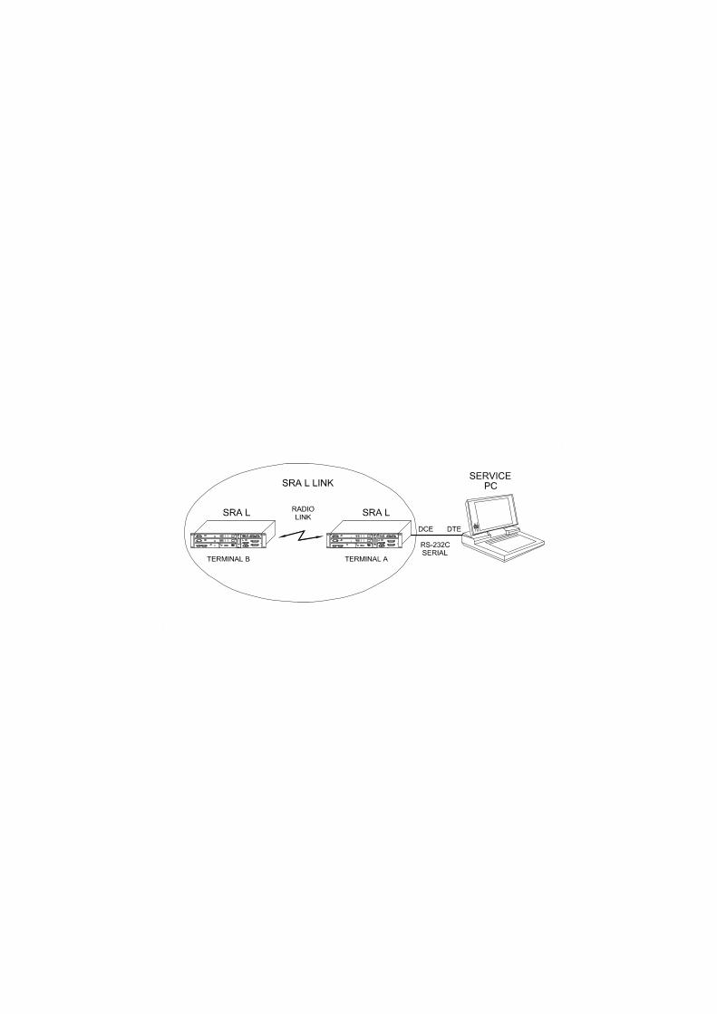
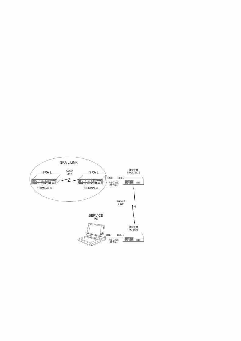
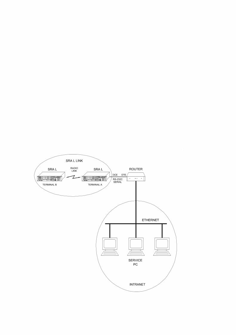
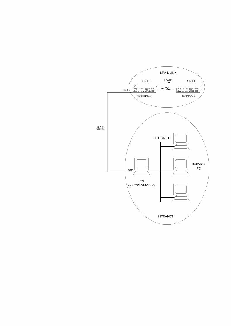
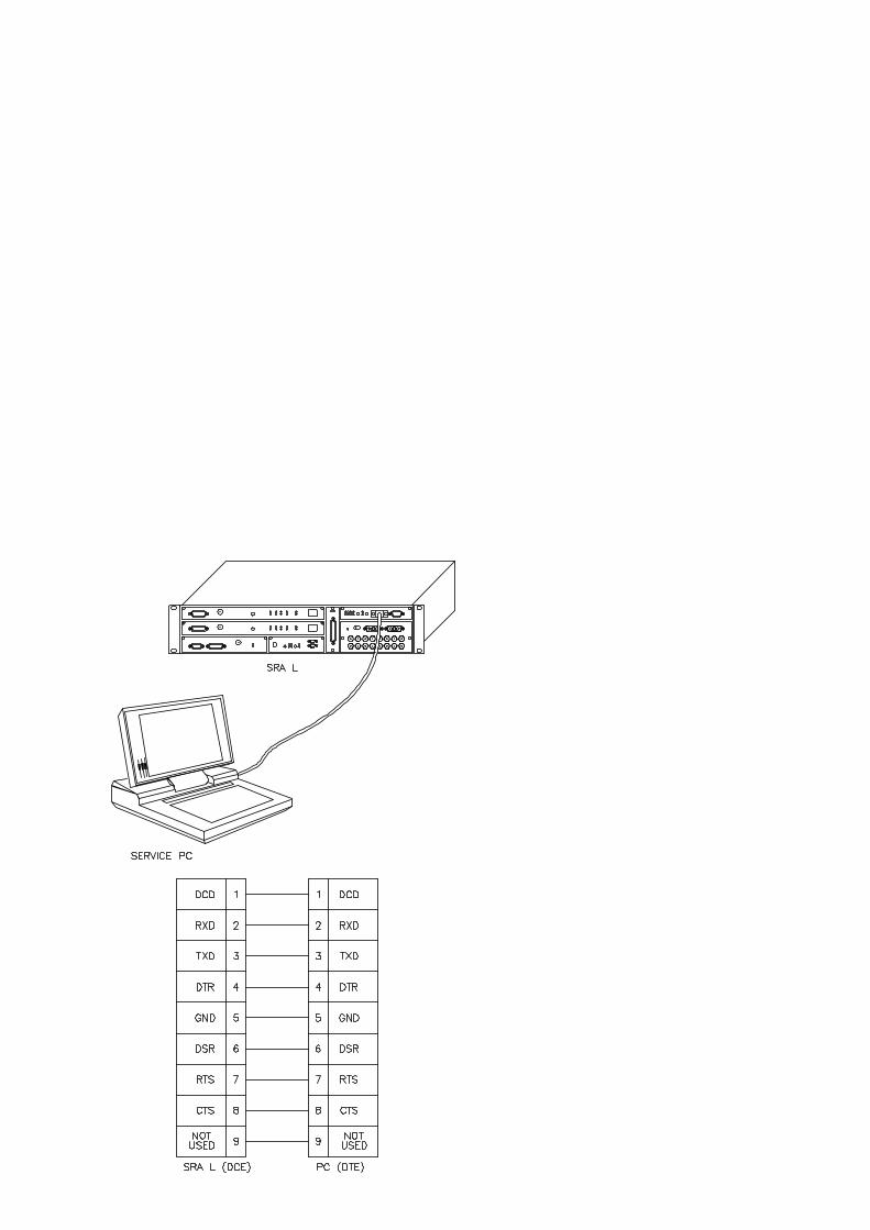

Link ViewerRadio equipment management system
Guide to use of Link Viewer program
53-011A2-500/EIssue 1, September 1999

Guide to use of Link Viewer program Link Viewer
53-011A2-500/E2/30 Issue 1, September 1999
FINE
BLANK PAGE
Link Viewer Guide to use of Link Viewer program
53-011A2-500/EIssue 1, September 1999 3/30
Contents
1 PROGRAM FUNCTIONS . . . . . . . . . . . . . . . . . . . . . . . . . . . . . . . . . . . . . . 6
2 USER INTERFACE . . . . . . . . . . . . . . . . . . . . . . . . . . . . . . . . . . . . . . . . . . . 72.1 Title bar . . . . . . . . . . . . . . . . . . . . . . . . . . . . . . . . . . . . . . . . . . . . . . . . . . . . . 72.2 Menu bar. . . . . . . . . . . . . . . . . . . . . . . . . . . . . . . . . . . . . . . . . . . . . . . . . . . . 82.3 Status bar . . . . . . . . . . . . . . . . . . . . . . . . . . . . . . . . . . . . . . . . . . . . . . . . . . . 82.4 Working area. . . . . . . . . . . . . . . . . . . . . . . . . . . . . . . . . . . . . . . . . . . . . . . . . 82.5 Tool bar. . . . . . . . . . . . . . . . . . . . . . . . . . . . . . . . . . . . . . . . . . . . . . . . . . . . 102.6 Scroll bars . . . . . . . . . . . . . . . . . . . . . . . . . . . . . . . . . . . . . . . . . . . . . . . . . . 10
3 PROGRAM START-UP . . . . . . . . . . . . . . . . . . . . . . . . . . . . . . . . . . . . . . . 113.1 Program start-up under Windows 3.1/3.11 . . . . . . . . . . . . . . . . . . . . . . . . . 113.2 Program start-up under Windows 95/NT . . . . . . . . . . . . . . . . . . . . . . . . . . 113.3 Opening of the link map . . . . . . . . . . . . . . . . . . . . . . . . . . . . . . . . . . . . . . . 143.4 Parameters on the control line of the Link Viewer program . . . . . . . . . . . . 15
4 SECURITY . . . . . . . . . . . . . . . . . . . . . . . . . . . . . . . . . . . . . . . . . . . . . . . . . 164.1 NE Security . . . . . . . . . . . . . . . . . . . . . . . . . . . . . . . . . . . . . . . . . . . . . . . . . 164.2 Map Security . . . . . . . . . . . . . . . . . . . . . . . . . . . . . . . . . . . . . . . . . . . . . . . . 164.3 Forcing procedure of the login phase . . . . . . . . . . . . . . . . . . . . . . . . . . . . . 17
5 DESCRIPTION OF THE MENUS . . . . . . . . . . . . . . . . . . . . . . . . . . . . . . . 195.1 File Menu . . . . . . . . . . . . . . . . . . . . . . . . . . . . . . . . . . . . . . . . . . . . . . . . . . 195.1.1 Open Map . . . . . . . . . . . . . . . . . . . . . . . . . . . . . . . . . . . . . . . . . . . . . . . . . . 195.1.2 Close Map. . . . . . . . . . . . . . . . . . . . . . . . . . . . . . . . . . . . . . . . . . . . . . . . . . 205.1.3 Print to File . . . . . . . . . . . . . . . . . . . . . . . . . . . . . . . . . . . . . . . . . . . . . . . . . 205.1.4 Exit . . . . . . . . . . . . . . . . . . . . . . . . . . . . . . . . . . . . . . . . . . . . . . . . . . . . . . . 215.2 Net-Element Menu . . . . . . . . . . . . . . . . . . . . . . . . . . . . . . . . . . . . . . . . . . . 225.2.1 Open . . . . . . . . . . . . . . . . . . . . . . . . . . . . . . . . . . . . . . . . . . . . . . . . . . . . . . 225.2.2 Open User. . . . . . . . . . . . . . . . . . . . . . . . . . . . . . . . . . . . . . . . . . . . . . . . . . 225.2.3 Close. . . . . . . . . . . . . . . . . . . . . . . . . . . . . . . . . . . . . . . . . . . . . . . . . . . . . . 235.2.4 Enable. . . . . . . . . . . . . . . . . . . . . . . . . . . . . . . . . . . . . . . . . . . . . . . . . . . . . 235.2.5 Disable . . . . . . . . . . . . . . . . . . . . . . . . . . . . . . . . . . . . . . . . . . . . . . . . . . . . 235.3 Options menu . . . . . . . . . . . . . . . . . . . . . . . . . . . . . . . . . . . . . . . . . . . . . . . 245.3.1 Colors . . . . . . . . . . . . . . . . . . . . . . . . . . . . . . . . . . . . . . . . . . . . . . . . . . . . . 245.3.2 Field Status . . . . . . . . . . . . . . . . . . . . . . . . . . . . . . . . . . . . . . . . . . . . . . . . . 265.3.3 Sounds . . . . . . . . . . . . . . . . . . . . . . . . . . . . . . . . . . . . . . . . . . . . . . . . . . . . 275.3.4 Move Map to Top . . . . . . . . . . . . . . . . . . . . . . . . . . . . . . . . . . . . . . . . . . . . 285.3.5 Move Map to Bottom. . . . . . . . . . . . . . . . . . . . . . . . . . . . . . . . . . . . . . . . . . 285.4 Window menu . . . . . . . . . . . . . . . . . . . . . . . . . . . . . . . . . . . . . . . . . . . . . . . 295.4.1 Cascade . . . . . . . . . . . . . . . . . . . . . . . . . . . . . . . . . . . . . . . . . . . . . . . . . . . 295.4.2 Tile . . . . . . . . . . . . . . . . . . . . . . . . . . . . . . . . . . . . . . . . . . . . . . . . . . . . . . . 295.4.3 Arrange Icons . . . . . . . . . . . . . . . . . . . . . . . . . . . . . . . . . . . . . . . . . . . . . . . 295.4.4 Close All . . . . . . . . . . . . . . . . . . . . . . . . . . . . . . . . . . . . . . . . . . . . . . . . . . . 295.5 Help menu. . . . . . . . . . . . . . . . . . . . . . . . . . . . . . . . . . . . . . . . . . . . . . . . . . 305.5.1 Contents . . . . . . . . . . . . . . . . . . . . . . . . . . . . . . . . . . . . . . . . . . . . . . . . . . . 305.5.2 Using Help . . . . . . . . . . . . . . . . . . . . . . . . . . . . . . . . . . . . . . . . . . . . . . . . . 305.5.3 About. . . . . . . . . . . . . . . . . . . . . . . . . . . . . . . . . . . . . . . . . . . . . . . . . . . . . . 30
Guide to use of Link Viewer program Link Viewer
53-011A2-500/E4/30 Issue 1, September 1999
IllustrationsFig. 1 User Interface of the Link Viewer program. . . . . . . . . . . . . . . . . . . . . . . . . . . 7
Fig. 2 Example of window for the selection of a value . . . . . . . . . . . . . . . . . . . . . . . 9
Fig. 3 Example of window for the data entry . . . . . . . . . . . . . . . . . . . . . . . . . . . . . . 9
Fig. 5 Programs Menu (Windows 95/NT) with LinkViewer folder. . . . . . . . . . . . . . 12
Fig. 6 Beginning presentation window of the Link Viewer program . . . . . . . . . . . . 13
Fig. 7 Base window of the Link Viewer program . . . . . . . . . . . . . . . . . . . . . . . . . . 13
Fig. 8 Program starting-up line for forcing the login phase (Windows 3.1/3.11) . . 18
Fig. 9 Feature window of the Link Viewer program (Windows 3.1/3.11) . . . . . . . . 18
Fig. 10 Program starting-up line for forcing the login phase (Windows 95/NT) . . . . 18
Fig. 11 Feature window of the Link Viewer program (Windows 95/NT) . . . . . . . . . . 18
Fig. 12 File menu . . . . . . . . . . . . . . . . . . . . . . . . . . . . . . . . . . . . . . . . . . . . . . . . . . . 19
Fig. 13 Window for the Open Map command of the File menu . . . . . . . . . . . . . . . . 19
Fig. 14 Map Security window . . . . . . . . . . . . . . . . . . . . . . . . . . . . . . . . . . . . . . . . . . 19
Fig. 15 Error Message caused by the opening of a map with sub-maps . . . . . . . . . 20
Fig. 16 Error Message caused by the opening of a map with more than three NEs 20
Fig. 17 Window for the map closing confirmation . . . . . . . . . . . . . . . . . . . . . . . . . . 20
Fig. 18 Window for the Print to File command of the File menu . . . . . . . . . . . . . . . 20
Fig. 19 Window for confirmation the file overwriting of the Print to File command. . 21
Fig. 20 Recording file of the NE remote-values . . . . . . . . . . . . . . . . . . . . . . . . . . . . 21
Fig. 21 Confirmation window for exiting the program. . . . . . . . . . . . . . . . . . . . . . . . 21
Fig. 22 Net-Element menu . . . . . . . . . . . . . . . . . . . . . . . . . . . . . . . . . . . . . . . . . . . . 22
Fig. 23 NE menu . . . . . . . . . . . . . . . . . . . . . . . . . . . . . . . . . . . . . . . . . . . . . . . . . . . 22
Fig. 24 NE menu activated pressing the right-hand push-button of the mouse . . . . 22
Fig. 25 Options menu. . . . . . . . . . . . . . . . . . . . . . . . . . . . . . . . . . . . . . . . . . . . . . . . 24
Fig. 26 COLOR SELECTION window . . . . . . . . . . . . . . . . . . . . . . . . . . . . . . . . . . . 25
Fig. 27 Color window . . . . . . . . . . . . . . . . . . . . . . . . . . . . . . . . . . . . . . . . . . . . . . . . 25
Fig. 28 Color window to define the customized colours . . . . . . . . . . . . . . . . . . . . . . 26
Fig. 29 FIELD STATUS DISPLAY SELECTION window . . . . . . . . . . . . . . . . . . . . . 27
Fig. 30 Selection of the strings for the signalling of the field status . . . . . . . . . . . . . 27
Fig. 31 Map Sounds Selection window . . . . . . . . . . . . . . . . . . . . . . . . . . . . . . . . . . 28
Fig. 32 Window menu . . . . . . . . . . . . . . . . . . . . . . . . . . . . . . . . . . . . . . . . . . . . . . . 29
Fig. 33 Help menu . . . . . . . . . . . . . . . . . . . . . . . . . . . . . . . . . . . . . . . . . . . . . . . . . . 30
Fig. 34 About Link Viewer window . . . . . . . . . . . . . . . . . . . . . . . . . . . . . . . . . . . . . . 30
Link Viewer Guide to use of Link Viewer program
53-011A2-500/EIssue 1, September 1999 5/30
TablesTab. 1 Tool bar. . . . . . . . . . . . . . . . . . . . . . . . . . . . . . . . . . . . . . . . . . . . . . . . . . . . 10
Tab. 2 Default configuration of the colours . . . . . . . . . . . . . . . . . . . . . . . . . . . . . . 24
Tab. 3 Defaulf configuration of the strings for the signalling of the field statuses . 26
Guide to use of Link Viewer program Link Viewer
53-011A2-500/E6/30 Issue 1, September 1999
1 PROGRAM FUNCTIONSThe Link Viewer program is an application one for Windows 3.1/3.11 and Windows95/NT environment for the supervisory of a radio equipment link (NE).The Link Viewer program allows the navigation inside the radio link, it displays the NEoperating status and allows interacting with them.The radio link to be managed is represented through a link map created by means of theNet Builder program (refer to the “Guide to use the Net Builder program”). Thisdocument contains all the information concerning the link configuration and it constitutesthe graphical interface for the access to the NEs.A radio link is usually composed by two radio equipments (two front-end terminals); itcan contain up to three radio equipments in case of add-drop configuration (twoterminals placed at the end and one intermediate add/drop repeater).Then, the Link Viewer program is not able to open maps that contain sub-maps andmore than three NEs.The Link Viewer program can manage radio links of different type:
– link of SDH radio equipments
– link of PDH radio equipments
– link of point-multipoint radio equipments.
The Link Viewer program allows the execution of the following main functions:
– to open and to display the link map (one link map);
– to set the connection with the NEs, activating such a connection at the mapopening;
– to execute, by means of a cyclic polling, the monitoring of the NEs connection andalarm status;
– to access to the single NE, that is to load the relevant configuration files andoperating menus;
– to configure and to control each single NE, through the relevant operating menu;
– to manage the security access (Security) to the NEs, that is to allow the accessonly to authorized users by means of passwords.
For each type of radio equipment, it is provided a specific software plug-in thatconstitutes the configuration and control application program.At the map opening, the Link Viewer program automatically detects the type of thepresent radio equipment, if the relevant plug-in has been installed. If it is present aparticular type of radio equipment and the relevant plug-in hasn’t been installed , theLink Viewer program detects its presence, but it is not able to recognize it and then tomanage it.It is possible to execute the installation of a plug-in for every type of radio equipment,also after the installation of the Link Viewer program. In such a case, if the Link Viewerprogram is already running, it is necessary to exit from the program and then to start upit again, to allow the loading of the new plug-in.
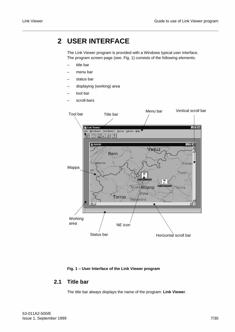
Link Viewer Guide to use of Link Viewer program
53-011A2-500/EIssue 1, September 1999 7/30
2 USER INTERFACEThe Link Viewer program is provided with a Windows typical user interface.The program screen page (see. Fig. 1) consists of the following elements:
– title bar
– menu bar
– status bar
– displaying (working) area
– tool bar
– scroll-bars
Fig. 1 – User Interface of the Link Viewer program
2.1 Title bar
The title bar always displays the name of the program: Link Viewer .
Status bar
Workingarea
Title barMenu bar
Tool bar
Horizontal scroll bar
NE icon
Mappa
Vertical scroll bar
Guide to use of Link Viewer program Link Viewer
53-011A2-500/E8/30 Issue 1, September 1999
2.2 Menu bar
The menu bar displays the following basic program menus:
– File
– Options
– Window
– Help .
When a map has been opened, the menu bar displays also the menus of the objectspresent into the map itself:
– Net-Element It contains the menus of the NEs present on the map.
– <name_NE>It is the menu of the actually selected NE.
The menus are Windows type ones. To select an option into a menu, it is necessary toposition the mouse on the menu, to press the left-hand push-button of the mouse and,keeping it pressed, to select the desired option; then release the left-hand push-buttonof the mouse to activate the selected option.
2.3 Status bar
The status bar displays messages and informations useful for the operator (the meaningof the menu commands, the status of the program or of the function actually onprogress, the details concerning the fields of the configuration and control windows,etc.).
2.4 Working area
The maps and the windows, opened using a command or selection, are displayed intothe working area. It is possible to display more windows at the same time, even if theybelong to different NEs.The title of a window is always preceeded by the name (IP address or mnemonicnemaplete) of the NE to which it is referred.The fields of the NE configuration and control windows can be of the following two types:
– read only: files concerning the status and alarm signals or not modifiableparameters
– read-write: fields concerning modifiable parameters.
It’s possible to modify the values of the fields, depending on the user class used toaccess to the NE:
– Read Only: it is possible only to read the values of the fields, not to change them
– Read Write: it is possible to change the values of the fields with the exception ofthe ones relevant to the windows reserved for the Admin user class
– Admin: it is possible to change the fields of every window.
Usually, it is possible to execute the following operations on the read-write type fields:
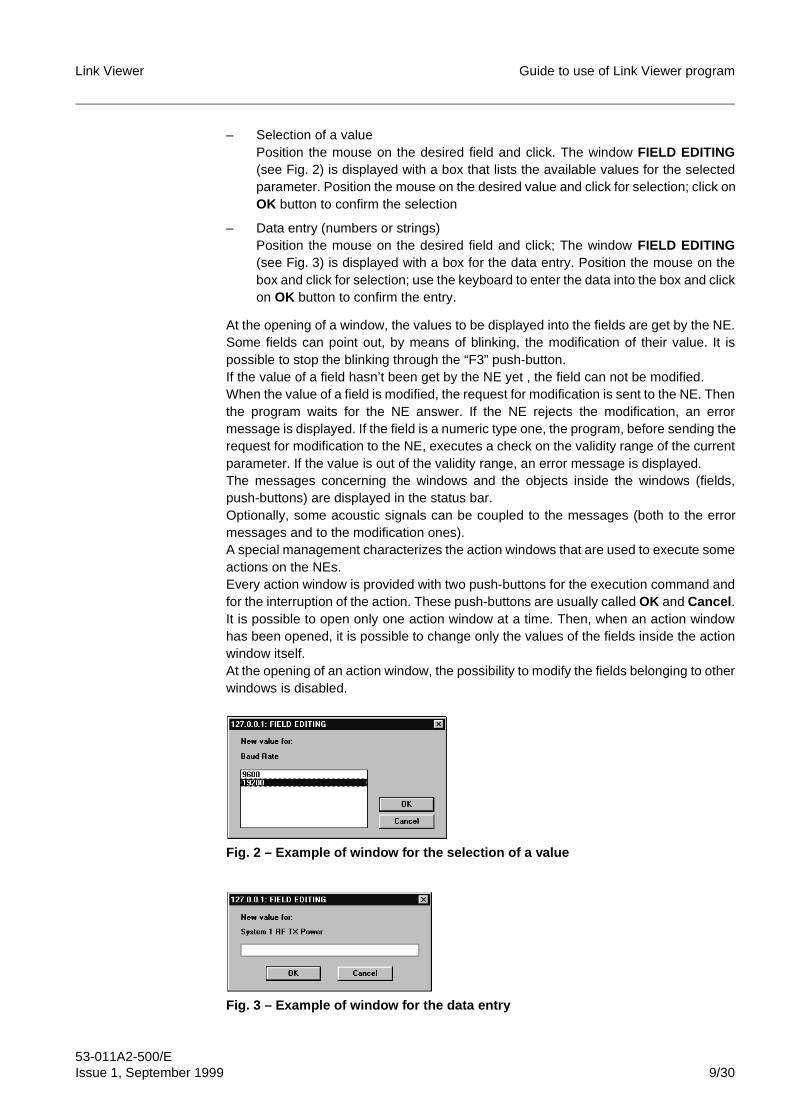
Link Viewer Guide to use of Link Viewer program
53-011A2-500/EIssue 1, September 1999 9/30
– Selection of a valuePosition the mouse on the desired field and click. The window FIELD EDITING(see Fig. 2) is displayed with a box that lists the available values for the selectedparameter. Position the mouse on the desired value and click for selection; click onOK button to confirm the selection
– Data entry (numbers or strings)Position the mouse on the desired field and click; The window FIELD EDITING(see Fig. 3) is displayed with a box for the data entry. Position the mouse on thebox and click for selection; use the keyboard to enter the data into the box and clickon OK button to confirm the entry.
At the opening of a window, the values to be displayed into the fields are get by the NE.Some fields can point out, by means of blinking, the modification of their value. It ispossible to stop the blinking through the “F3” push-button.If the value of a field hasn’t been get by the NE yet , the field can not be modified.When the value of a field is modified, the request for modification is sent to the NE. Thenthe program waits for the NE answer. If the NE rejects the modification, an errormessage is displayed. If the field is a numeric type one, the program, before sending therequest for modification to the NE, executes a check on the validity range of the currentparameter. If the value is out of the validity range, an error message is displayed.The messages concerning the windows and the objects inside the windows (fields,push-buttons) are displayed in the status bar.Optionally, some acoustic signals can be coupled to the messages (both to the errormessages and to the modification ones).A special management characterizes the action windows that are used to execute someactions on the NEs.Every action window is provided with two push-buttons for the execution command andfor the interruption of the action. These push-buttons are usually called OK and Cancel .It is possible to open only one action window at a time. Then, when an action windowhas been opened, it is possible to change only the values of the fields inside the actionwindow itself.At the opening of an action window, the possibility to modify the fields belonging to otherwindows is disabled.
Fig. 2 – Example of window for the selection of a value
Fig. 3 – Example of window for the data entry
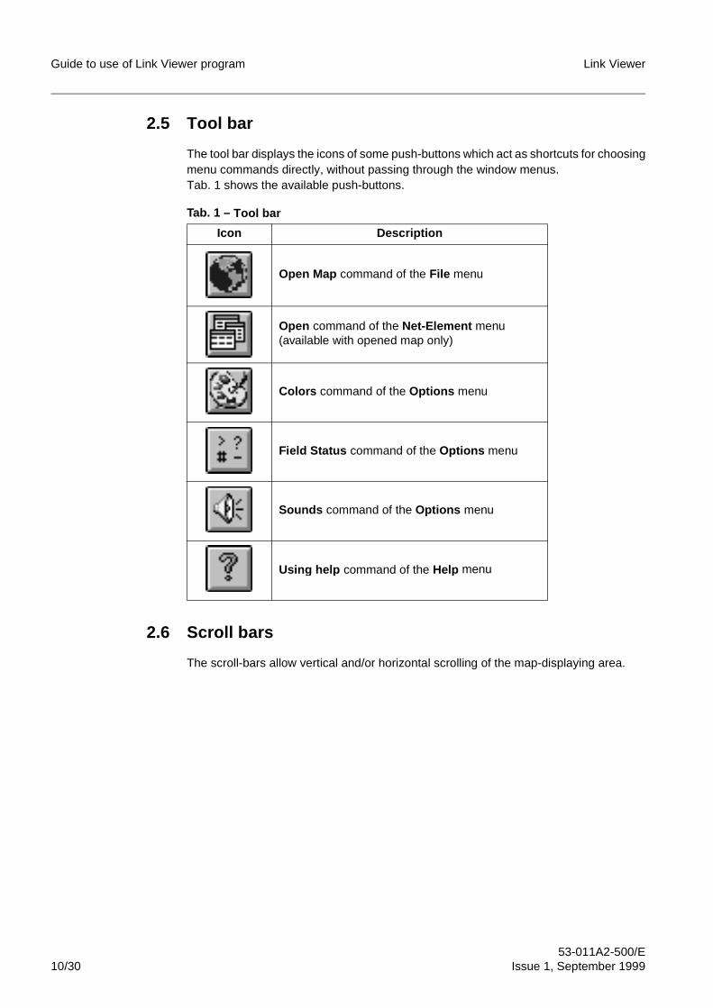
Guide to use of Link Viewer program Link Viewer
53-011A2-500/E10/30 Issue 1, September 1999
2.5 Tool bar
The tool bar displays the icons of some push-buttons which act as shortcuts for choosingmenu commands directly, without passing through the window menus.Tab. 1 shows the available push-buttons.
Tab. 1 – Tool bar
2.6 Scroll bars
The scroll-bars allow vertical and/or horizontal scrolling of the map-displaying area.
Icon Description
Open Map command of the File menu
Open command of the Net-Element menu(available with opened map only)
Colors command of the Options menu
Field Status command of the Options menu
Sounds command of the Options menu
Usin g help command of the Help menu
Link Viewer Guide to use of Link Viewer program
53-011A2-500/EIssue 1, September 1999 11/30
3 PROGRAM START-UPBefore starting-up the Link Viewer program, it is necessary to check the activation of theconnection between the PC where there is the program and the radio link.The connection modes between the PC and the radio link depends on several factors,such as for instance the following ones:
– the operating system present on the PC
– the interface type used on the PC for the connection (serial RS-232 or Ethernet)
– the radio equipment type present into the link
– the possible use of modems and/or routers
– the possible use of a proxy.
For a more detailed description of the connection modes and of the relevant activationprocedures, refer to the document “Connection to the Radio Link”.
3.1 Program start-up under Windows 3.1/3.11
The start-up procedure of the Link Viewer program under Windows 3.1/3.11 is thefollowing one:
– Click twice on the Link Viewer icon into the LinkViewer group (see Fig. 4).
– At the beginning, the program presentation window is displayed (see Fig. 6) and,after some seconds, the program base window is displayed (see Fig. 7). Clickingon the presentation window, it is possible to exit, to close the window itself and topass directly to the program base window.
3.2 Program start-up under Windows 95/NT
The start-up procedure of the Link Viewer program under Windows 95/NT is thefollowing one:
– Click on the Start push-button and, into the Programs menu, select theLinkViewer directory and, then, Link Viewer (see Fig. 5).
– At the beginning, the program presentation window is displayed (see Fig. 6) and,after some seconds, the program base window is displayed (see Fig. 7). Clickingon the presentation window, it is possible to exit, to close the window itself and topass directly to the program base window.
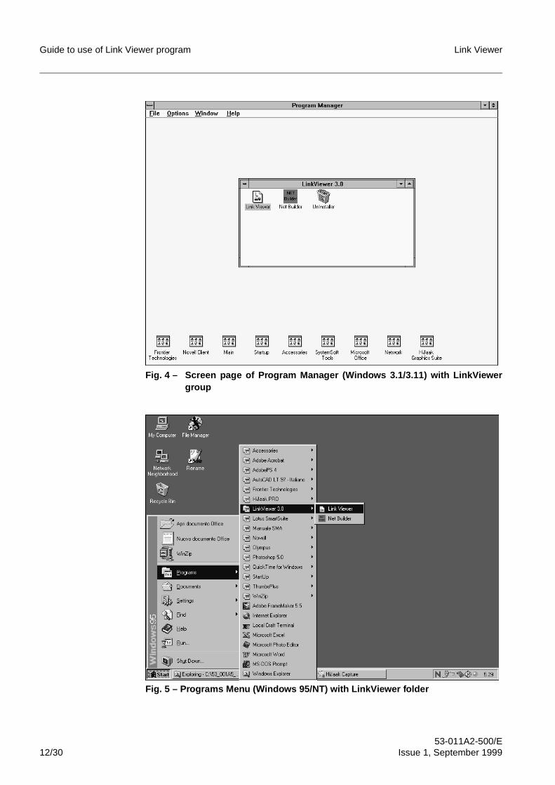
Guide to use of Link Viewer program Link Viewer
53-011A2-500/E12/30 Issue 1, September 1999
Fig. 4 – Screen page of Program Manager (Windows 3.1/3.11) with LinkViewergroup
Fig. 5 – Programs Menu (Windows 95/NT) with LinkViewer folder
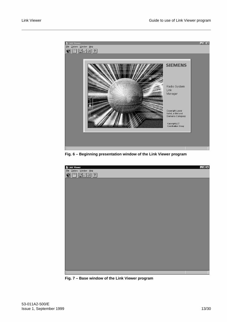
Link Viewer Guide to use of Link Viewer program
53-011A2-500/EIssue 1, September 1999 13/30
Fig. 6 – Beginning presentation window of the Link Viewer program
Fig. 7 – Base window of the Link Viewer program

Guide to use of Link Viewer program Link Viewer
53-011A2-500/E14/30 Issue 1, September 1999
3.3 Opening of the link map
After having started the Link Viewer program, it is necessary to open the link map usingthe Open Map command of the File menu to access to the radio link (refer to par. 5.1.1).Before opening the link map, the Link Viewer program checks its congruence (the maphasn’t to contain sub-maps or more than three NEs).Each NE of the map is represented through an icon and a label. The icon type and thelabel background colour show the NE status.At the map opening, the Net-Element menu is added in the menu bar. Inside this menu,one menu for each NE of the map is created .Then, on the side of the Net-Element menu, the menu relevant to the actually selectedNE is always displayed (<name_NE> ). This feature allows executing the commands onthe selected NE without searching every time the relevant menu under the Net-Elementmenu. Changing the selected NE, also the <name_NE> menu changes.At the map opening, the program tries to connect to all the enabled NEs. For each NE,the connection phase is executed as described below:
– if an error during the communication is detected (for instance: not existing NE), anicon showing that the NE is not connected is displayed (not intentional disablingstatus)
– if the connection is successfully executed, the program tries to recognize the radioequipment type:• if the recognition is successfully executed, the relevant configuration file is
loaded and a pre-defined icon showing the radio equipment type is displayed.Then, into the corresponding NE menu, the operating menu that allows theNE configuration and control is added.
• if the recognition is not successfully executed (for instance: the plug-in forsuch a type of radio equipment is not installed), an icon showing that the radioequipment type is not supported is displayed.
The program cyclically executes an automatic connection attempt towards the NEs thatactually are in the not intentional disabling status.It is always possible to know the cause of the disconnection for a NE. Positioning thecursor on the icon of a disconnected NE, a message is displayed into the status barshowing the reason for the disconnection.The program executes a periodical polling to monitor of the connection and alarm(severity) status of the NEs. The possible values of severity for a NE are the followingones:
– disconnected
– normal
– test
– warning
– minor
– major
– critical.
The status of a intentional disabling for a NE is signalled through a proper icon.
Link Viewer Guide to use of Link Viewer program
53-011A2-500/EIssue 1, September 1999 15/30
3.4 Parameters on the control line of the Link Viewer program
It is possible to start-up the Link Viewer program by inserting on the control line thefollowing parameters:
– -pIt allows forcing the execution of the login phase during the access to a NE,independently from the enabling status of the NE Security (refer to par. 4.3).
– -traceIt allows activating the tracing management of the link operations.
– -map <name_map>At the opening of the map displayed into the <name_map> field, all the not disabledNEs are connected and sequentially opened.
– -ip <address_IP> -pa <address_proxy> -pp <port_proxy>It allows creating a new map with the NE having the specified IP address. Thebackground is the same one used for the configuration and control windows of theNE.If the connection uses a proxy, it is possible to specify the proxy address and port.At the map opening, the NE is connected and opened.
– -nologoIt allows preventing the displaying of the presentation window (logo) at the programstarting-up.
Each parameter can be written without distinction in capital letters or in small letters andit can be preceded by the character “-” or “/”.
Guide to use of Link Viewer program Link Viewer
53-011A2-500/E16/30 Issue 1, September 1999
4 SECURITY
4.1 NE Security
The Security allows the access to NE only to the authorized users. Each user ischaracterized by a user class and by a password. The user class defines the accessprivileges to the NEs.The Security configuration (enabling status and password) is specific for each NE andit is stored into the NE memory.The system provides the following three different user classes:
– Read Only: it allows the access to the functions in reading mode only;
– Read Write: it allows the access to the functions as in reading mode as in writingone, with the exception of the functions reserved for the Admin user class. For suchfunctions, the access is in reading mode only;
– Admin: it allows the access to all the functions as in reading mode as in writing one.
It is available also the Diagnostic user class, but only for the use inside the factory.It is possible to set/change the Security configuration by the NE operating menu, only ifthe access is executed using the Admin user class. When the access to a NE takesplace with enabled Security, the login phase is executed: it consists of the activation ofa window where the user has to specify the user class and the relevant password.It is always possible to force the execution of the login phase, independently from theenabling status of the NE Security, starting-up the Link Viewer program with the -poption (refer to par. 4.3). In case of NE with disabled Security and Link Viewer programstarted-up without the -p, option, it is possible to access to the NE with the Admin userclass. The only restriction is that it is not possible to change the settings relevant to theSecurity (enabling status and password). The Security enabling prevents the connectionto a NE of more operators at the same time with the Admin or Read Write user class,preventing conflicts and configuration errors.
4.2 Map Security
It is available a map Security with the following functions:
– to allow the map opening to authorized users only. The user classes are the sameones provided for the NEs;
– to associate all the passwords of the link map NEs to a single map password, foreach user class.
The map Security allows the user to access to the map and to its NEs with his authorizeduser class, using the map password only.The configuration of the map Security can be executed by means of the Net Builderprogram (refer to document “Guide to use of Net Builder program”). This programallows:
– enabling/disabling the map Security
– setting/changing the access passwords to the map for the several user classes;
– storing, into the map file, the access passwords to the NEs for the several userclasses.
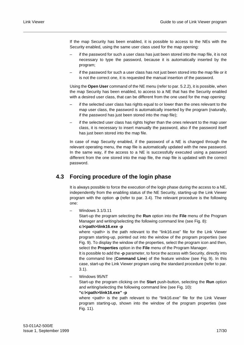
Link Viewer Guide to use of Link Viewer program
53-011A2-500/EIssue 1, September 1999 17/30
If the map Security has been enabled, it is possible to access to the NEs with theSecurity enabled, using the same user class used for the map opening:
– if the password for such a user class has just been stored into the map file, it is notnecessary to type the password, because it is automatically inserted by theprogram;
– if the password for such a user class has not just been stored into the map file or itis not the correct one, it is requested the manual insertion of the password.
Using the Open User command of the NE menu (refer to par. 5.2.2), it is possible, whenthe map Security has been enabled, to access to a NE that has the Security enabledwith a desired user class, that can be different from the one used for the map opening:
– if the selected user class has rights equal to or lower than the ones relevant to themap user class, the password is automatically inserted by the program (naturally,if the password has just been stored into the map file);
– if the selected user class has rights higher than the ones relevant to the map userclass, it is necessary to insert manually the password, also if the password itselfhas just been stored into the map file.
In case of map Security enabled, if the password of a NE is changed through therelevant operating menu, the map file is automatically updated with the new password.In the same way, if the access to a NE is successfully executed using a passworddifferent from the one stored into the map file, the map file is updated with the correctpassword.
4.3 Forcing procedure of the login phase
It is always possible to force the execution of the login phase during the access to a NE,independently from the enabling status of the NE Security, starting-up the Link Viewerprogram with the option -p (refer to par. 3.4). The relevant procedure is the followingone:
– Windows 3.1/3.11Start-up the program selecting the Run option into the File menu of the ProgramManager and writing/selecting the following command line (see Fig. 8):c:\<path>\link16.exe -pwhere <path> is the path relevant to the “link16.exe” file for the Link Viewerprogram starting-up, pointed out into the window of the program properties (seeFig. 9). To display the window of the properties, select the program icon and then,select the Properties option in the File menu of the Program Manager.It is possible to add the -p parameter, to force the access with Security, directly intothe command line (Command Line ) of the feature window (see Fig. 9). In thiscase, start-up the Link Viewer program using the standard procedure (refer to par.3.1).
– Windows 95/NTStart-up the program clicking on the Start push-button, selecting the Run optionand writing/selecting the following command line (see Fig. 10):“c:\<path>\link16.exe” -pwhere <path> is the path relevant to the “link16.exe” file for the Link Viewerprogram starting-up, shown into the window of the program properties (seeFig. 11).
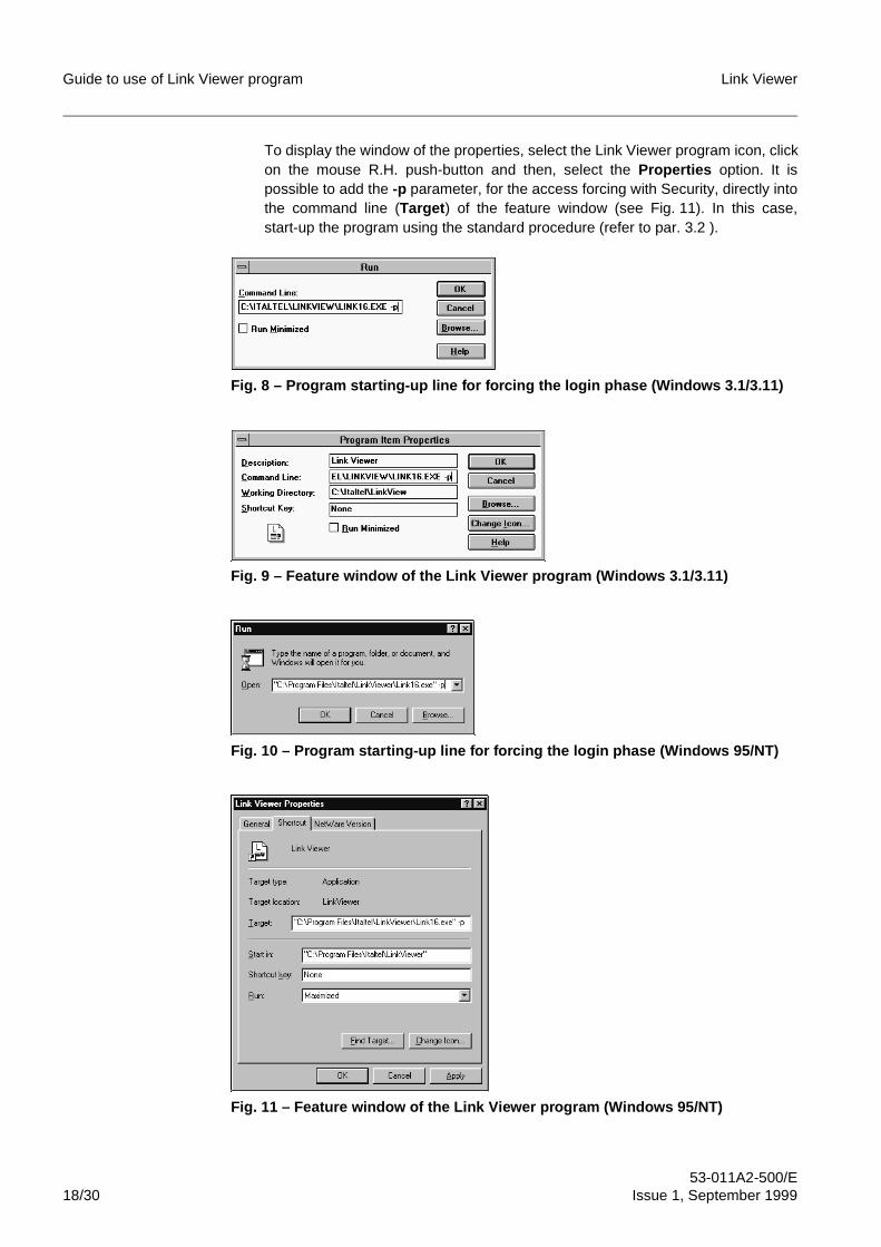
Guide to use of Link Viewer program Link Viewer
53-011A2-500/E18/30 Issue 1, September 1999
To display the window of the properties, select the Link Viewer program icon, clickon the mouse R.H. push-button and then, select the Properties option. It ispossible to add the -p parameter, for the access forcing with Security, directly intothe command line (Target ) of the feature window (see Fig. 11). In this case,start-up the program using the standard procedure (refer to par. 3.2 ).
Fig. 8 – Program starting-up line for forcing the login phase (Windows 3.1/3.11)
Fig. 9 – Feature window of the Link Viewer program (Windows 3.1/3.11)
Fig. 10 – Program starting-up line for forcing the login phase (Windows 95/NT)
Fig. 11 – Feature window of the Link Viewer program (Windows 95/NT)
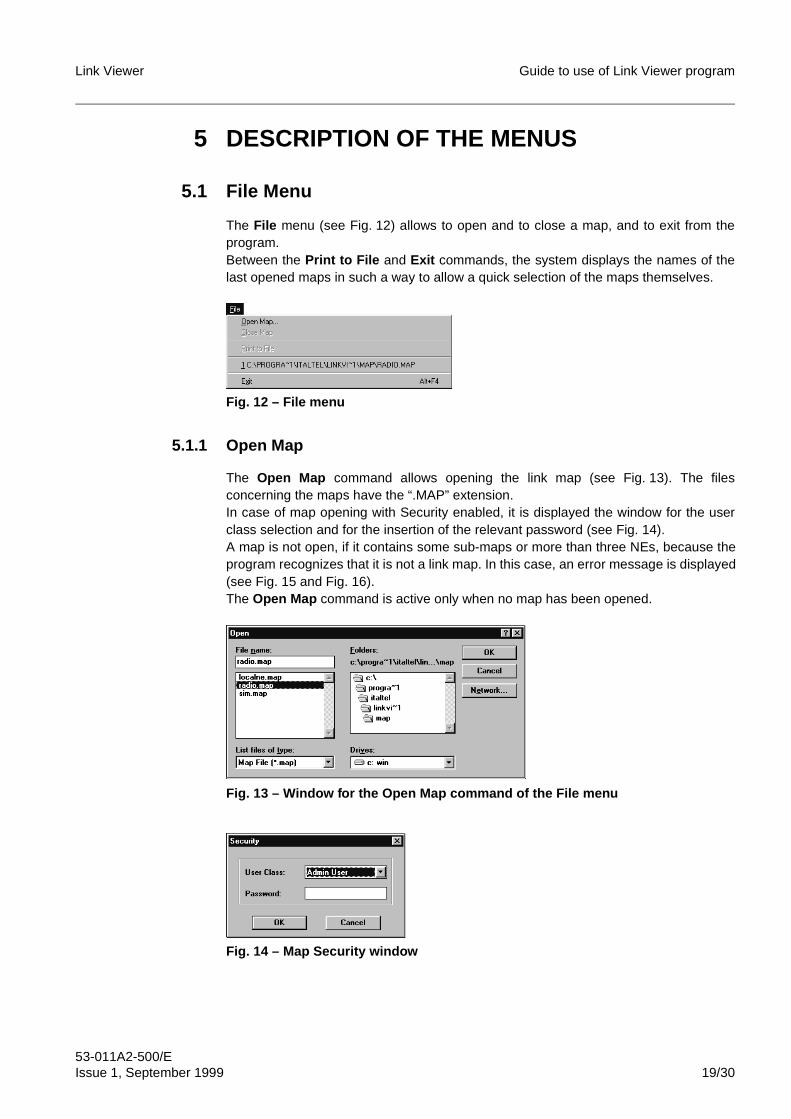
Link Viewer Guide to use of Link Viewer program
53-011A2-500/EIssue 1, September 1999 19/30
5 DESCRIPTION OF THE MENUS
5.1 File Menu
The File menu (see Fig. 12) allows to open and to close a map, and to exit from theprogram.Between the Print to File and Exit commands, the system displays the names of thelast opened maps in such a way to allow a quick selection of the maps themselves.
Fig. 12 – File menu
5.1.1 Open Map
The Open Map command allows opening the link map (see Fig. 13). The filesconcerning the maps have the “.MAP” extension.In case of map opening with Security enabled, it is displayed the window for the userclass selection and for the insertion of the relevant password (see Fig. 14).A map is not open, if it contains some sub-maps or more than three NEs, because theprogram recognizes that it is not a link map. In this case, an error message is displayed(see Fig. 15 and Fig. 16).The Open Map command is active only when no map has been opened.
Fig. 13 – Window for the Open Map command of the File menu
Fig. 14 – Map Security window
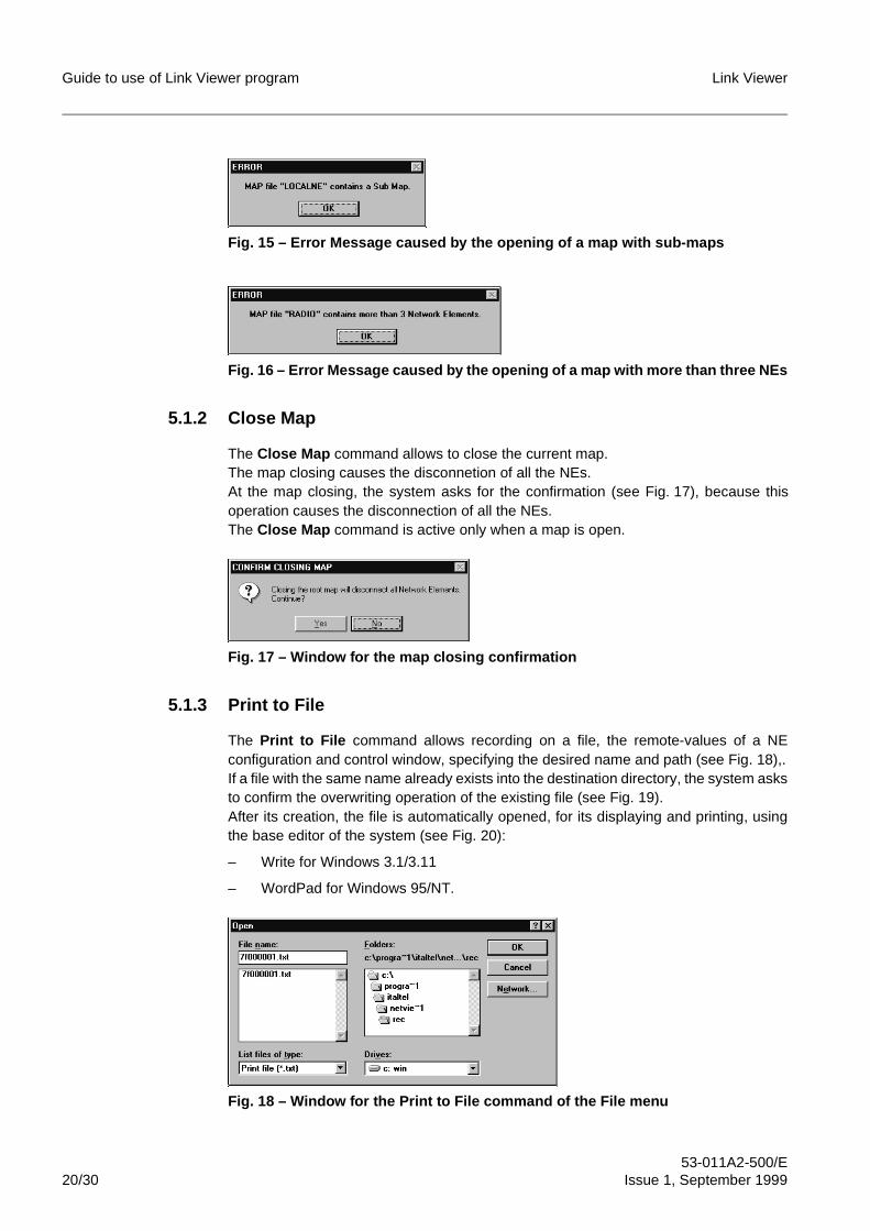
Guide to use of Link Viewer program Link Viewer
53-011A2-500/E20/30 Issue 1, September 1999
Fig. 15 – Error Message caused by the opening of a map with sub-maps
Fig. 16 – Error Message caused by the opening of a map with more than three NEs
5.1.2 Close Map
The Close Map command allows to close the current map.The map closing causes the disconnetion of all the NEs.At the map closing, the system asks for the confirmation (see Fig. 17), because thisoperation causes the disconnection of all the NEs.The Close Map command is active only when a map is open.
Fig. 17 – Window for the map closing confirmation
5.1.3 Print to File
The Print to File command allows recording on a file, the remote-values of a NEconfiguration and control window, specifying the desired name and path (see Fig. 18),.If a file with the same name already exists into the destination directory, the system asksto confirm the overwriting operation of the existing file (see Fig. 19).After its creation, the file is automatically opened, for its displaying and printing, usingthe base editor of the system (see Fig. 20):
– Write for Windows 3.1/3.11
– WordPad for Windows 95/NT.
Fig. 18 – Window for the Print to File command of the File menu
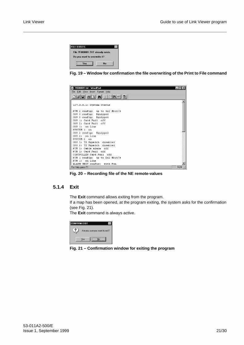
Link Viewer Guide to use of Link Viewer program
53-011A2-500/EIssue 1, September 1999 21/30
Fig. 19 – Window for confirmation the file overwriting of the Print to File command
Fig. 20 – Recording file of the NE remote-values
5.1.4 Exit
The Exit command allows exiting from the program.If a map has been opened, at the program exiting, the system asks for the confirmation(see Fig. 21).The Exit command is always active.
Fig. 21 – Confirmation window for exiting the program
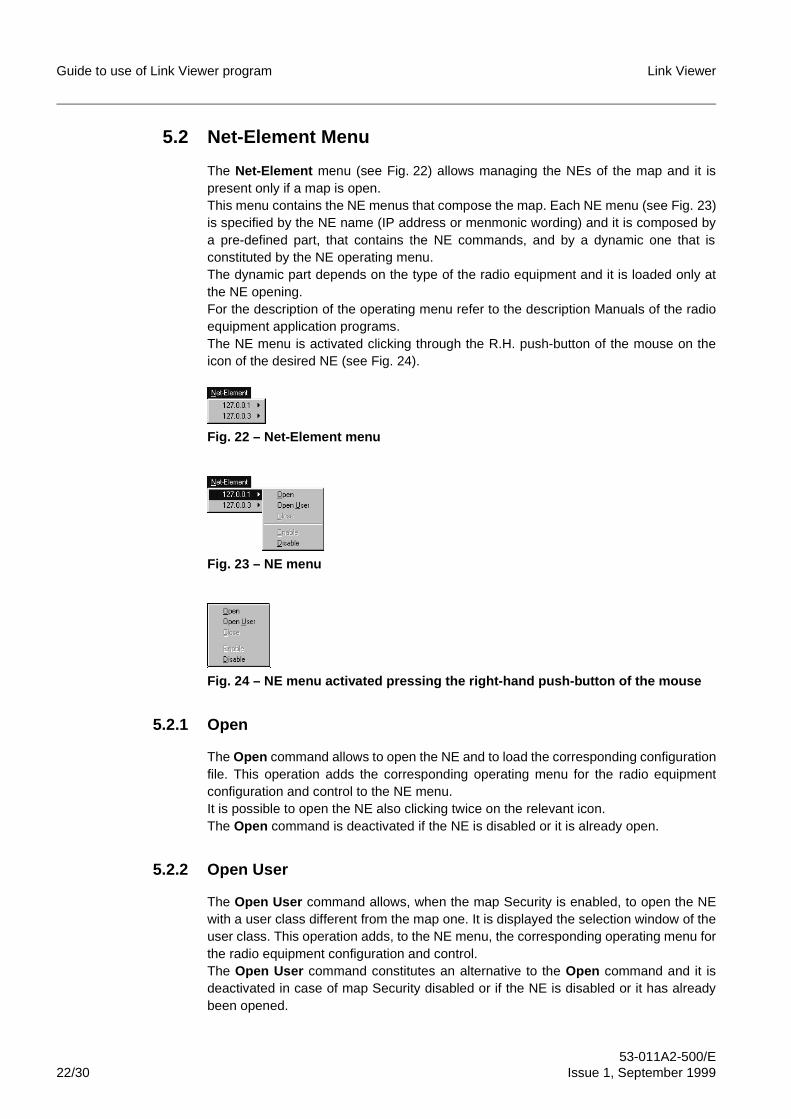
Guide to use of Link Viewer program Link Viewer
53-011A2-500/E22/30 Issue 1, September 1999
5.2 Net-Element Menu
The Net-Element menu (see Fig. 22) allows managing the NEs of the map and it ispresent only if a map is open.This menu contains the NE menus that compose the map. Each NE menu (see Fig. 23)is specified by the NE name (IP address or menmonic wording) and it is composed bya pre-defined part, that contains the NE commands, and by a dynamic one that isconstituted by the NE operating menu.The dynamic part depends on the type of the radio equipment and it is loaded only atthe NE opening.For the description of the operating menu refer to the description Manuals of the radioequipment application programs.The NE menu is activated clicking through the R.H. push-button of the mouse on theicon of the desired NE (see Fig. 24).
Fig. 22 – Net-Element menu
Fig. 23 – NE menu
Fig. 24 – NE menu activated pressing the right-hand push-button of the mouse
5.2.1 Open
The Open command allows to open the NE and to load the corresponding configurationfile. This operation adds the corresponding operating menu for the radio equipmentconfiguration and control to the NE menu.It is possible to open the NE also clicking twice on the relevant icon.The Open command is deactivated if the NE is disabled or it is already open.
5.2.2 Open User
The Open User command allows, when the map Security is enabled, to open the NEwith a user class different from the map one. It is displayed the selection window of theuser class. This operation adds, to the NE menu, the corresponding operating menu forthe radio equipment configuration and control.The Open User command constitutes an alternative to the Open command and it isdeactivated in case of map Security disabled or if the NE is disabled or it has alreadybeen opened.
Link Viewer Guide to use of Link Viewer program
53-011A2-500/EIssue 1, September 1999 23/30
5.2.3 Close
The Close command allows closing the NE.This operation causes the closing of all the NE configuration and control windows andthe removal of the operating menu from the NE menu.The Close command is activated only if the NE has been opened.
5.2.4 Enable
The Enable command allows to enable the connection towards the NE.The command is activated only if the connection towards NE is disabled.
5.2.5 Disable
The Disable command allows to disable the connection towards the NE.The command is activated only if the connection towards NE is enabled.
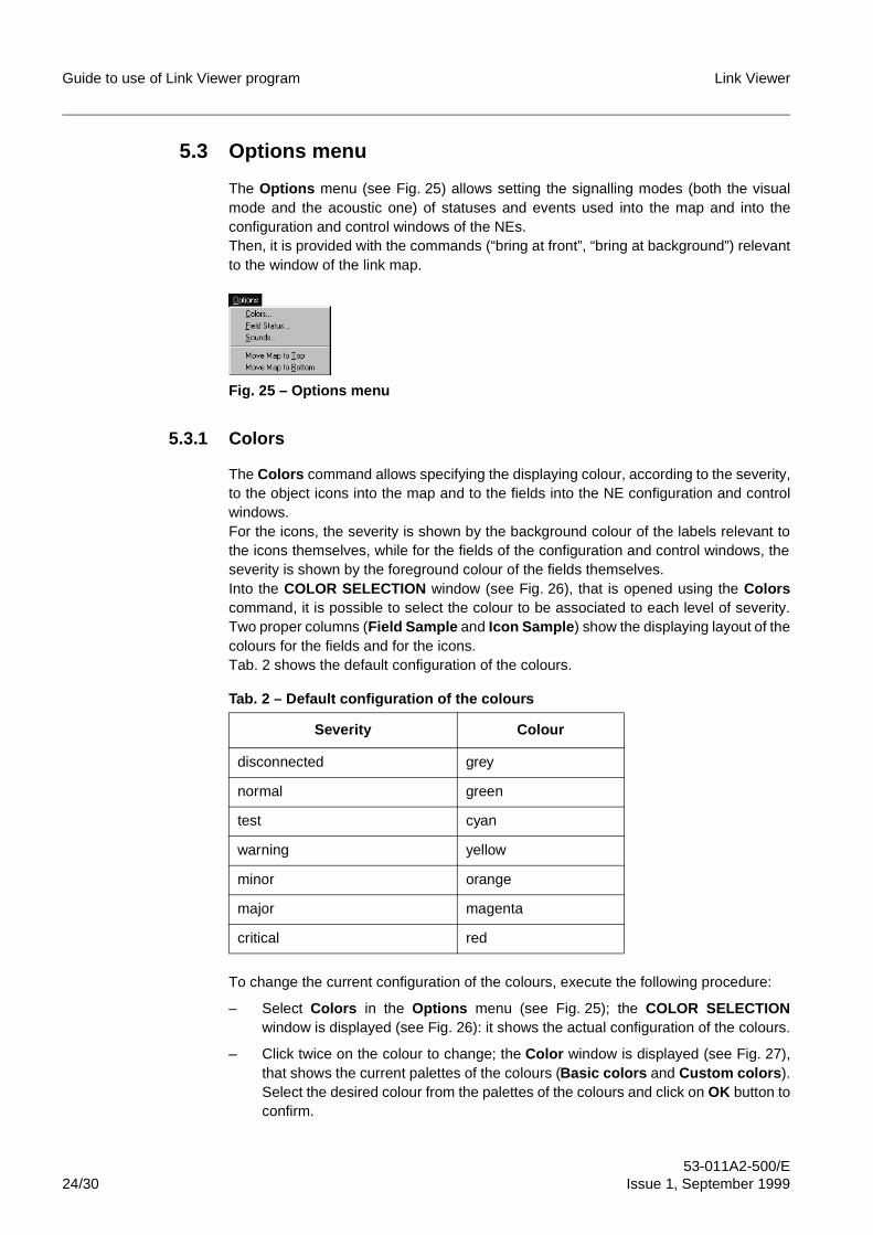
Guide to use of Link Viewer program Link Viewer
53-011A2-500/E24/30 Issue 1, September 1999
5.3 Options menu
The Options menu (see Fig. 25) allows setting the signalling modes (both the visualmode and the acoustic one) of statuses and events used into the map and into theconfiguration and control windows of the NEs.Then, it is provided with the commands (“bring at front”, “bring at background”) relevantto the window of the link map.
Fig. 25 – Options menu
5.3.1 Colors
The Colors command allows specifying the displaying colour, according to the severity,to the object icons into the map and to the fields into the NE configuration and controlwindows.For the icons, the severity is shown by the background colour of the labels relevant tothe icons themselves, while for the fields of the configuration and control windows, theseverity is shown by the foreground colour of the fields themselves.Into the COLOR SELECTION window (see Fig. 26), that is opened using the Colorscommand, it is possible to select the colour to be associated to each level of severity.Two proper columns (Field Sample and Icon Sample ) show the displaying layout of thecolours for the fields and for the icons.Tab. 2 shows the default configuration of the colours.
Tab. 2 – Default configuration of the colours
To change the current configuration of the colours, execute the following procedure:
– Select Colors in the Options menu (see Fig. 25); the COLOR SELECTIONwindow is displayed (see Fig. 26): it shows the actual configuration of the colours.
– Click twice on the colour to change; the Color window is displayed (see Fig. 27),that shows the current palettes of the colours (Basic colors and Custom colors ).Select the desired colour from the palettes of the colours and click on OK button toconfirm.
Severity Colour
disconnected grey
normal green
test cyan
warning yellow
minor orange
major magenta
critical red
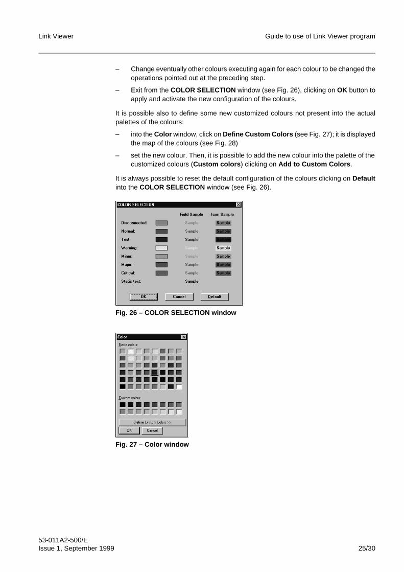
Link Viewer Guide to use of Link Viewer program
53-011A2-500/EIssue 1, September 1999 25/30
– Change eventually other colours executing again for each colour to be changed theoperations pointed out at the preceding step.
– Exit from the COLOR SELECTION window (see Fig. 26), clicking on OK button toapply and activate the new configuration of the colours.
It is possible also to define some new customized colours not present into the actualpalettes of the colours:
– into the Color window, click on Define Custom Colors (see Fig. 27); it is displayedthe map of the colours (see Fig. 28)
– set the new colour. Then, it is possible to add the new colour into the palette of thecustomized colours (Custom colors ) clicking on Add to Custom Colors .
It is always possible to reset the default configuration of the colours clicking on Defaultinto the COLOR SELECTION window (see Fig. 26).
Fig. 26 – COLOR SELECTION window
Fig. 27 – Color window
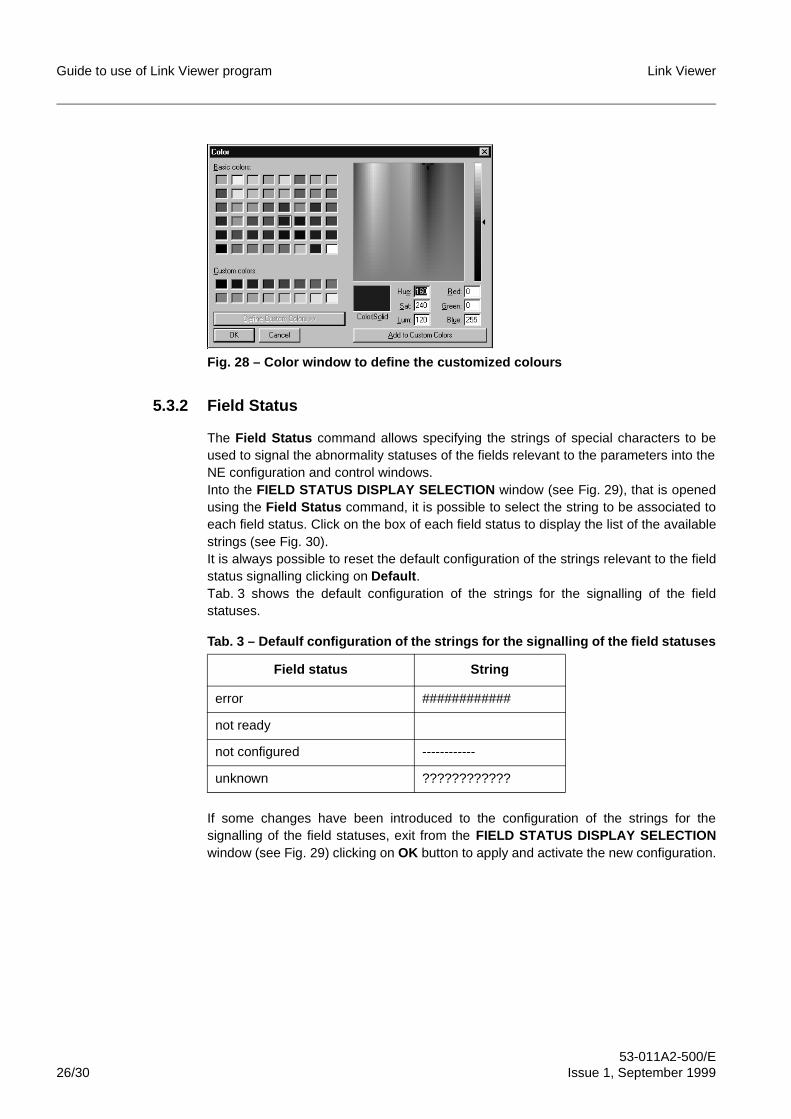
Guide to use of Link Viewer program Link Viewer
53-011A2-500/E26/30 Issue 1, September 1999
Fig. 28 – Color window to define the customized colours
5.3.2 Field Status
The Field Status command allows specifying the strings of special characters to beused to signal the abnormality statuses of the fields relevant to the parameters into theNE configuration and control windows.Into the FIELD STATUS DISPLAY SELECTION window (see Fig. 29), that is openedusing the Field Status command, it is possible to select the string to be associated toeach field status. Click on the box of each field status to display the list of the availablestrings (see Fig. 30).It is always possible to reset the default configuration of the strings relevant to the fieldstatus signalling clicking on Default .Tab. 3 shows the default configuration of the strings for the signalling of the fieldstatuses.
Tab. 3 – Defaulf configuration of the strings for the signalling of the field statuses
If some changes have been introduced to the configuration of the strings for thesignalling of the field statuses, exit from the FIELD STATUS DISPLAY SELECTIONwindow (see Fig. 29) clicking on OK button to apply and activate the new configuration.
Field status String
error ############
not ready
not configured ------------
unknown ????????????
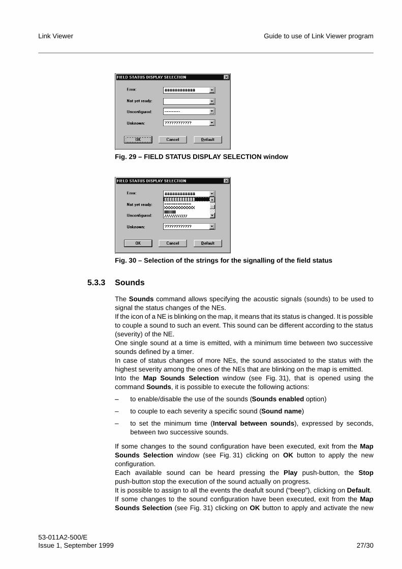
Link Viewer Guide to use of Link Viewer program
53-011A2-500/EIssue 1, September 1999 27/30
Fig. 29 – FIELD STATUS DISPLAY SELECTION window
Fig. 30 – Selection of the strings for the signalling of the field status
5.3.3 Sounds
The Sounds command allows specifying the acoustic signals (sounds) to be used tosignal the status changes of the NEs.If the icon of a NE is blinking on the map, it means that its status is changed. It is possibleto couple a sound to such an event. This sound can be different according to the status(severity) of the NE.One single sound at a time is emitted, with a minimum time between two successivesounds defined by a timer.In case of status changes of more NEs, the sound associated to the status with thehighest severity among the ones of the NEs that are blinking on the map is emitted.Into the Map Sounds Selection window (see Fig. 31), that is opened using thecommand Sounds , it is possible to execute the following actions:
– to enable/disable the use of the sounds (Sounds enabled option)
– to couple to each severity a specific sound (Sound name )
– to set the minimum time (Interval between sounds ), expressed by seconds,between two successive sounds.
If some changes to the sound configuration have been executed, exit from the MapSounds Selection window (see Fig. 31) clicking on OK button to apply the newconfiguration.Each available sound can be heard pressing the Play push-button, the Stoppush-button stop the execution of the sound actually on progress.It is possible to assign to all the events the deafult sound (“beep”), clicking on Default .If some changes to the sound configuration have been executed, exit from the MapSounds Selection (see Fig. 31) clicking on OK button to apply and activate the new
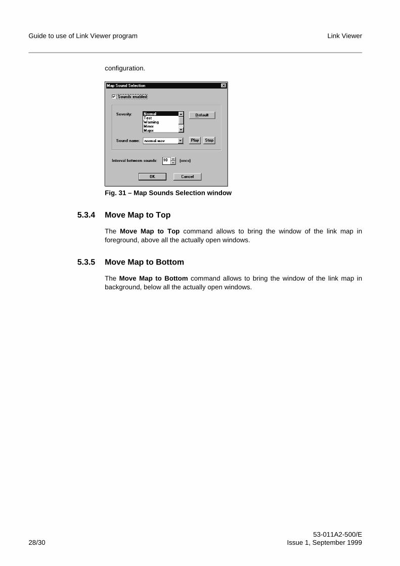
Guide to use of Link Viewer program Link Viewer
53-011A2-500/E28/30 Issue 1, September 1999
configuration.
Fig. 31 – Map Sounds Selection window
5.3.4 Move Map to Top
The Move Map to Top command allows to bring the window of the link map inforeground, above all the actually open windows.
5.3.5 Move Map to Bottom
The Move Map to Bottom command allows to bring the window of the link map inbackground, below all the actually open windows.
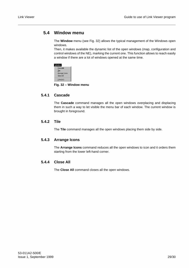
Link Viewer Guide to use of Link Viewer program
53-011A2-500/EIssue 1, September 1999 29/30
5.4 Window menu
The Window menu (see Fig. 32) allows the typical management of the Windows openwindows.Then, it makes available the dynamic list of the open windows (map, configuration andcontrol windows of the NE), marking the current one. This function allows to reach easilya window if there are a lot of windows opened at the same time.
Fig. 32 – Window menu
5.4.1 Cascade
The Cascade command manages all the open windows overplacing and displacingthem in such a way to let visible the menu bar of each window. The current window isbrought in foreground.
5.4.2 Tile
The Tile command manages all the open windows placing them side by side.
5.4.3 Arrange Icons
The Arrange Icons command reduces all the open windows to icon and it orders themstarting from the lower left-hand corner.
5.4.4 Close All
The Close All command closes all the open windows.
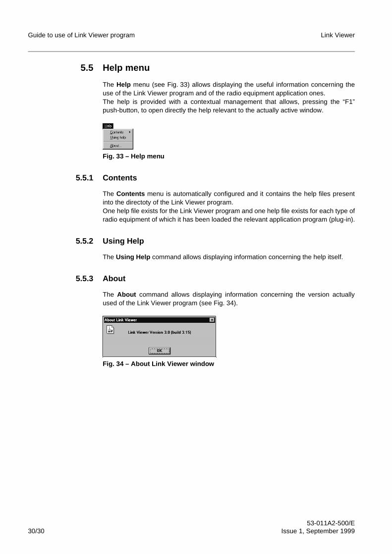
Guide to use of Link Viewer program Link Viewer
53-011A2-500/E30/30 Issue 1, September 1999
5.5 Help menu
The Help menu (see Fig. 33) allows displaying the useful information concerning theuse of the Link Viewer program and of the radio equipment application ones.The help is provided with a contextual management that allows, pressing the “F1”push-button, to open directly the help relevant to the actually active window.
Fig. 33 – Help menu
5.5.1 Contents
The Contents menu is automatically configured and it contains the help files presentinto the directoty of the Link Viewer program.One help file exists for the Link Viewer program and one help file exists for each type ofradio equipment of which it has been loaded the relevant application program (plug-in).
5.5.2 Using Help
The Using Help command allows displaying information concerning the help itself.
5.5.3 About
The About command allows displaying information concerning the version actuallyused of the Link Viewer program (see Fig. 34).
Fig. 34 – About Link Viewer window
FINE
Net Viewer/Link ViewerRadio equipment management system
Guide to use of Net Builder
54-00001-501/EIssue 1, September 1999

Guide to use of Net Builder Net Viewer/Link Viewer
54-00001-501/E2/30 Issue 1, September 1999
FINE
BLANK PAGE
Net Viewer/Link Viewer Guide to use of Net Builder
54-00001-501/EIssue 1, September 1999 3/30
Contents
1 PROGRAM FEATURES . . . . . . . . . . . . . . . . . . . . . . . . . . . . . . . . . . . . . . . 7
2 USER INTERFACE . . . . . . . . . . . . . . . . . . . . . . . . . . . . . . . . . . . . . . . . . . . 92.1 Title bar . . . . . . . . . . . . . . . . . . . . . . . . . . . . . . . . . . . . . . . . . . . . . . . . . . . . . 92.2 Menu bar. . . . . . . . . . . . . . . . . . . . . . . . . . . . . . . . . . . . . . . . . . . . . . . . . . . 102.3 Status bar . . . . . . . . . . . . . . . . . . . . . . . . . . . . . . . . . . . . . . . . . . . . . . . . . . 102.4 Scroll bars . . . . . . . . . . . . . . . . . . . . . . . . . . . . . . . . . . . . . . . . . . . . . . . . . . 102.5 Working area. . . . . . . . . . . . . . . . . . . . . . . . . . . . . . . . . . . . . . . . . . . . . . . . 102.6 Icons for objects description . . . . . . . . . . . . . . . . . . . . . . . . . . . . . . . . . . . . 10
3 PROGRAM START UP . . . . . . . . . . . . . . . . . . . . . . . . . . . . . . . . . . . . . . . 113.1 Program start-up under Windows 3.1/3.11 . . . . . . . . . . . . . . . . . . . . . . . . . 113.2 Program start-up under Windows 95/NT . . . . . . . . . . . . . . . . . . . . . . . . . . 11
4 MENU DESCRIPTION OF THE MENU TOOLBAR . . . . . . . . . . . . . . . . . . 144.1 File menu . . . . . . . . . . . . . . . . . . . . . . . . . . . . . . . . . . . . . . . . . . . . . . . . . . 144.1.1 New. . . . . . . . . . . . . . . . . . . . . . . . . . . . . . . . . . . . . . . . . . . . . . . . . . . . . . . 144.1.2 Open . . . . . . . . . . . . . . . . . . . . . . . . . . . . . . . . . . . . . . . . . . . . . . . . . . . . . . 144.1.3 Close. . . . . . . . . . . . . . . . . . . . . . . . . . . . . . . . . . . . . . . . . . . . . . . . . . . . . . 154.1.4 Save . . . . . . . . . . . . . . . . . . . . . . . . . . . . . . . . . . . . . . . . . . . . . . . . . . . . . . 154.1.5 Save As. . . . . . . . . . . . . . . . . . . . . . . . . . . . . . . . . . . . . . . . . . . . . . . . . . . . 154.1.6 Exit . . . . . . . . . . . . . . . . . . . . . . . . . . . . . . . . . . . . . . . . . . . . . . . . . . . . . . . 164.2 Edit menu . . . . . . . . . . . . . . . . . . . . . . . . . . . . . . . . . . . . . . . . . . . . . . . . . . 174.2.1 Open Map . . . . . . . . . . . . . . . . . . . . . . . . . . . . . . . . . . . . . . . . . . . . . . . . . . 174.2.2 New. . . . . . . . . . . . . . . . . . . . . . . . . . . . . . . . . . . . . . . . . . . . . . . . . . . . . . . 174.2.2.1 Net-Element . . . . . . . . . . . . . . . . . . . . . . . . . . . . . . . . . . . . . . . . . . . . . . . . 174.2.2.2 Sub-Map . . . . . . . . . . . . . . . . . . . . . . . . . . . . . . . . . . . . . . . . . . . . . . . . . . . 184.2.3 Delete . . . . . . . . . . . . . . . . . . . . . . . . . . . . . . . . . . . . . . . . . . . . . . . . . . . . . 194.2.4 Background. . . . . . . . . . . . . . . . . . . . . . . . . . . . . . . . . . . . . . . . . . . . . . . . . 194.2.4.1 Insert . . . . . . . . . . . . . . . . . . . . . . . . . . . . . . . . . . . . . . . . . . . . . . . . . . . . . . 204.2.4.2 Delete . . . . . . . . . . . . . . . . . . . . . . . . . . . . . . . . . . . . . . . . . . . . . . . . . . . . . 204.2.4.3 Change . . . . . . . . . . . . . . . . . . . . . . . . . . . . . . . . . . . . . . . . . . . . . . . . . . . . 204.2.5 Security . . . . . . . . . . . . . . . . . . . . . . . . . . . . . . . . . . . . . . . . . . . . . . . . . . . . 204.2.5.1 Enable Security. . . . . . . . . . . . . . . . . . . . . . . . . . . . . . . . . . . . . . . . . . . . . . 214.2.5.2 Disable Security . . . . . . . . . . . . . . . . . . . . . . . . . . . . . . . . . . . . . . . . . . . . . 224.2.5.3 Passwords . . . . . . . . . . . . . . . . . . . . . . . . . . . . . . . . . . . . . . . . . . . . . . . . . 224.2.6 Properties . . . . . . . . . . . . . . . . . . . . . . . . . . . . . . . . . . . . . . . . . . . . . . . . . . 234.3 Window menu . . . . . . . . . . . . . . . . . . . . . . . . . . . . . . . . . . . . . . . . . . . . . . . 254.3.1 Cascade . . . . . . . . . . . . . . . . . . . . . . . . . . . . . . . . . . . . . . . . . . . . . . . . . . . 254.3.2 Tile . . . . . . . . . . . . . . . . . . . . . . . . . . . . . . . . . . . . . . . . . . . . . . . . . . . . . . . 254.3.3 Arrange Icons . . . . . . . . . . . . . . . . . . . . . . . . . . . . . . . . . . . . . . . . . . . . . . . 254.3.4 Close All . . . . . . . . . . . . . . . . . . . . . . . . . . . . . . . . . . . . . . . . . . . . . . . . . . . 254.3.5 Show Map Tree. . . . . . . . . . . . . . . . . . . . . . . . . . . . . . . . . . . . . . . . . . . . . . 254.4 Help menu. . . . . . . . . . . . . . . . . . . . . . . . . . . . . . . . . . . . . . . . . . . . . . . . . . 274.4.1 Contents . . . . . . . . . . . . . . . . . . . . . . . . . . . . . . . . . . . . . . . . . . . . . . . . . . . 274.4.2 Using Help . . . . . . . . . . . . . . . . . . . . . . . . . . . . . . . . . . . . . . . . . . . . . . . . . 274.4.3 About. . . . . . . . . . . . . . . . . . . . . . . . . . . . . . . . . . . . . . . . . . . . . . . . . . . . . . 27
Guide to use of Net Builder Net Viewer/Link Viewer
54-00001-501/E4/30 Issue 1, September 1999
5 MENUS OF THE MOUSE RIGHT HAND PUSH-BUTTON . . . . . . . . . . . . 285.1 Map menu . . . . . . . . . . . . . . . . . . . . . . . . . . . . . . . . . . . . . . . . . . . . . . . . . . 285.2 Sub-map menu . . . . . . . . . . . . . . . . . . . . . . . . . . . . . . . . . . . . . . . . . . . . . . 285.3 NE menu . . . . . . . . . . . . . . . . . . . . . . . . . . . . . . . . . . . . . . . . . . . . . . . . . . . 29
6 PARENT FUNCTION . . . . . . . . . . . . . . . . . . . . . . . . . . . . . . . . . . . . . . . . . 30
Net Viewer/Link Viewer Guide to use of Net Builder
54-00001-501/EIssue 1, September 1999 5/30
IllustrationsFig. 1 Example of radio equipment network and link map . . . . . . . . . . . . . . . . . . . 8
Fig. 2 User interface of the Net Builder program . . . . . . . . . . . . . . . . . . . . . . . . . . 9
Fig. 3 Program Manager screen (Windows 3.1/3.11) with NetViewer group . . . . 11
Fig. 4 Program Manager screen (Windows 3.1/3.11) with LinkViewer group . . . . 12
Fig. 5 Programs menu (Windows 95/NT) with NetViewer folder. . . . . . . . . . . . . . 12
Fig. 6 Programs menu (Windows 95/NT) with LinkViewer folder . . . . . . . . . . . . . 13
Fig. 7 Initial screen of the Net Builder program. . . . . . . . . . . . . . . . . . . . . . . . . . . 13
Fig. 8 File menu . . . . . . . . . . . . . . . . . . . . . . . . . . . . . . . . . . . . . . . . . . . . . . . . . . 14
Fig. 9 Window for the Open command of the File menu. . . . . . . . . . . . . . . . . . . . 14
Fig. 10 Security window for map opening . . . . . . . . . . . . . . . . . . . . . . . . . . . . . . . . 15
Fig. 11 Saving confirmation window of the map changes. . . . . . . . . . . . . . . . . . . . 15
Fig. 12 Window for the Save As command of the File menu . . . . . . . . . . . . . . . . . 16
Fig. 13 Saving confirmation window for the Save As command . . . . . . . . . . . . . . . 16
Fig. 14 Confirmation window for the program exit . . . . . . . . . . . . . . . . . . . . . . . . . 16
Fig. 15 Confirmation window for the map saving at the program exit . . . . . . . . . . . 16
Fig. 16 Edit menu . . . . . . . . . . . . . . . . . . . . . . . . . . . . . . . . . . . . . . . . . . . . . . . . . . 17
Fig. 17 New menu. . . . . . . . . . . . . . . . . . . . . . . . . . . . . . . . . . . . . . . . . . . . . . . . . . 17
Fig. 18 Window for the insertion of a new NE. . . . . . . . . . . . . . . . . . . . . . . . . . . . . 18
Fig. 19 Window for the insertion of a new sub-map . . . . . . . . . . . . . . . . . . . . . . . . 19
Fig. 20 Confirmation window for the deleting of a sub-map . . . . . . . . . . . . . . . . . . 19
Fig. 21 Background Menu. . . . . . . . . . . . . . . . . . . . . . . . . . . . . . . . . . . . . . . . . . . . 19
Fig. 22 Window for the Insert command of the Background menu . . . . . . . . . . . . . 20
Fig. 23 Window for the Change command of the Background menu . . . . . . . . . . . 20
Fig. 24 Security menu . . . . . . . . . . . . . . . . . . . . . . . . . . . . . . . . . . . . . . . . . . . . . . . 21
Fig. 25 Window for Security enabling . . . . . . . . . . . . . . . . . . . . . . . . . . . . . . . . . . . 21
Fig. 26 Confirmation window for Security disabling . . . . . . . . . . . . . . . . . . . . . . . . 22
Fig. 27 Window of the map passwords . . . . . . . . . . . . . . . . . . . . . . . . . . . . . . . . . . 22
Fig. 28 Window of the NE passwords . . . . . . . . . . . . . . . . . . . . . . . . . . . . . . . . . . . 23
Fig. 29 Window of the sub-map properties . . . . . . . . . . . . . . . . . . . . . . . . . . . . . . . 24
Fig. 30 Window of the NE properties . . . . . . . . . . . . . . . . . . . . . . . . . . . . . . . . . . . 24
Fig. 31 Window menu . . . . . . . . . . . . . . . . . . . . . . . . . . . . . . . . . . . . . . . . . . . . . . . 25
Fig. 32 Map Tree window . . . . . . . . . . . . . . . . . . . . . . . . . . . . . . . . . . . . . . . . . . . . 26
Fig. 33 Icons used into Map Tree . . . . . . . . . . . . . . . . . . . . . . . . . . . . . . . . . . . . . . 26
Fig. 34 Map Tree hierarchy. . . . . . . . . . . . . . . . . . . . . . . . . . . . . . . . . . . . . . . . . . . 26
Fig. 35 Help menu. . . . . . . . . . . . . . . . . . . . . . . . . . . . . . . . . . . . . . . . . . . . . . . . . . 27
Fig. 36 About Net Builder window. . . . . . . . . . . . . . . . . . . . . . . . . . . . . . . . . . . . . . 27
Fig. 37 Map sub-menu and menu . . . . . . . . . . . . . . . . . . . . . . . . . . . . . . . . . . . . . . 28
Fig. 38 Sub-map menu and sub-menu . . . . . . . . . . . . . . . . . . . . . . . . . . . . . . . . . . 28
Fig. 39 NE menu . . . . . . . . . . . . . . . . . . . . . . . . . . . . . . . . . . . . . . . . . . . . . . . . . . . 29
Fig. 40 System menu with Parent function . . . . . . . . . . . . . . . . . . . . . . . . . . . . . . . 30
Guide to use of Net Builder Net Viewer/Link Viewer
54-00001-501/E6/30 Issue 1, September 1999
TablesTab. 1 Icons for objects description. . . . . . . . . . . . . . . . . . . . . . . . . . . . . . . . . . . . . 10

Net Viewer/Link Viewer Guide to use of Net Builder
54-00001-501/EIssue 1, September 1999 7/30
1 PROGRAM FEATURESThe Net Builder program is an application program for Windows 3.1/3.11 and Windows95/NT: it allows to create/change network/link maps constituting the graphical interfaceof the Net Viewer/Link Viewer program for connection with radio equipment (NE). Then,this program allows setting the parameters for the security access (Security) to the mapand to the NEs. This program is intented for network/link administrators.To create a map, following this procedure:
– compose the radio equipment network/link drawing, using a common graphicalWindows application supporting the “.BMP” graphical format (e.g. Paintbrush)
– import into Net Builder the radio equipment network/link drawing, that constitutesthe map background
– apply the NE icons in the predefined positions on the drawing
– assign the corresponding IP address (that has to be a univocal) to each NE
– eventually, set the passwords for the security access to the map and to the radioequipments
– save the map with the desired name in a “.MAP” format file
It is possible to create also some maps with tree structure, that is composed by a mainmap and one or more sub-maps in cascade. The sub-maps allow to group the NEs inthe desired mode and with more levels. The program is equipped with a standard mapfor connection to the local radio equipment.
The radio equipment network/link drawing can be of any type (e.g. geographical mapindicating the location of the various stations, a block diagram showing all thenetwork/link interconnections, etc...). During the composition of the drawing, sufficientspace must be left in the position of the NEs to allow subsequent positioning of thecorresponding icons, in order to obtain a orderly and readable map.
Fig. 1 shows an example of the radio equipment network/link map.
It is possible to use a mnemonic acronyms instead of the numeric IP addressesif it has been defined a host table.
☞ If the operator wants to create a personalized local map, it is necessary to assignthe numeric IP address 192.168.255.3 which constitutes the predefined and nonmodifiable local connection address for every radio equipment.
A link map has not to contain sub-maps or more than three NEs, because theLink Viewer program is able only to open maps that comply with suchrequirements.
i
i
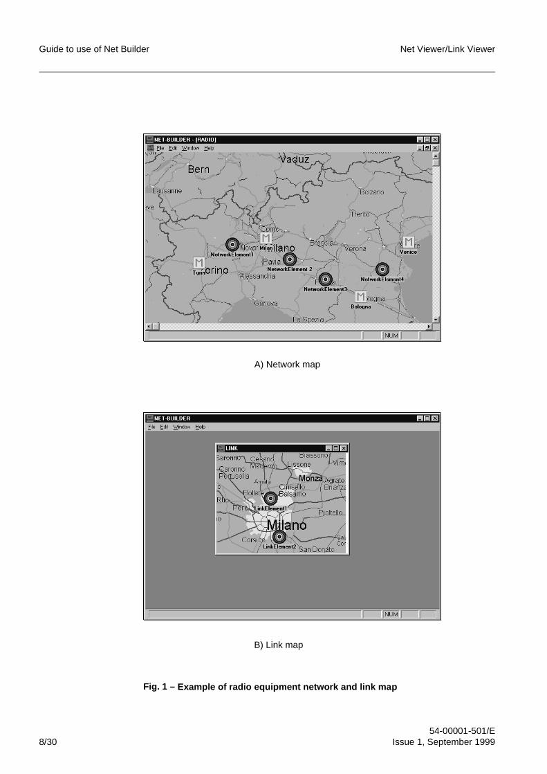
Guide to use of Net Builder Net Viewer/Link Viewer
54-00001-501/E8/30 Issue 1, September 1999
Fig. 1 – Example of radio e quipment network and link ma p
A) Network map
B) Link map
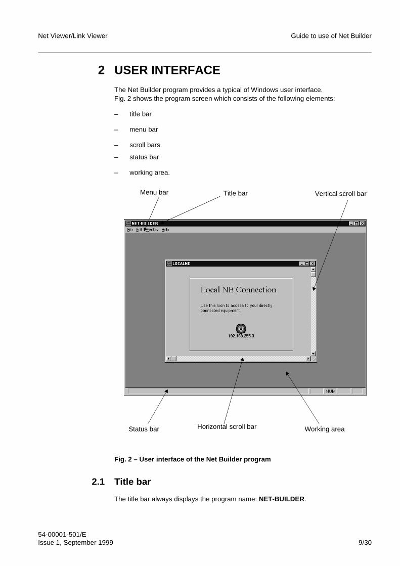
Net Viewer/Link Viewer Guide to use of Net Builder
54-00001-501/EIssue 1, September 1999 9/30
2 USER INTERFACEThe Net Builder program provides a typical of Windows user interface.Fig. 2 shows the program screen which consists of the following elements:
– title bar
– menu bar
– scroll bars
– status bar
– working area.
Fig. 2 – User interface of the Net Builder program
2.1 Title bar
The title bar always displays the program name: NET-BUILDER .
Status bar Horizontal scroll bar Working area
Vertical scroll barTitle barMenu bar
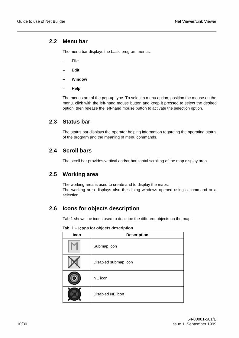
Guide to use of Net Builder Net Viewer/Link Viewer
54-00001-501/E10/30 Issue 1, September 1999
2.2 Menu bar
The menu bar displays the basic program menus:
– File
– Edit
– Window
– Help .
The menus are of the pop-up type. To select a menu option, position the mouse on themenu, click with the left-hand mouse button and keep it pressed to select the desiredoption; then release the left-hand mouse button to activate the selection option.
2.3 Status bar
The status bar displays the operator helping information regarding the operating statusof the program and the meaning of menu commands.
2.4 Scroll bars
The scroll bar provides vertical and/or horizontal scrolling of the map display area
2.5 Working area
The working area is used to create and to display the maps.The working area displays also the dialog windows opened using a command or aselection.
2.6 Icons for objects description
Tab.1 shows the icons used to describe the different objects on the map.
Tab. 1 – Icon s for objects description
Icon Description
Submap icon
Disabled submap icon
NE icon
Disabled NE icon
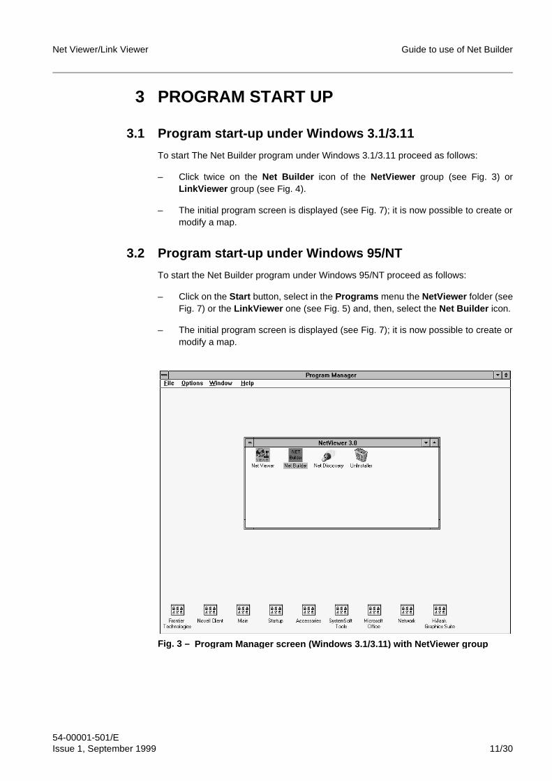
Net Viewer/Link Viewer Guide to use of Net Builder
54-00001-501/EIssue 1, September 1999 11/30
3 PROGRAM START UP
3.1 Program start-up under Windows 3.1/3.11
To start The Net Builder program under Windows 3.1/3.11 proceed as follows:
– Click twice on the Net Builder icon of the NetViewer group (see Fig. 3) orLinkViewer group (see Fig. 4).
– The initial program screen is displayed (see Fig. 7); it is now possible to create ormodify a map.
3.2 Program start-up under Windows 95/NT
To start the Net Builder program under Windows 95/NT proceed as follows:
– Click on the Start button, select in the Programs menu the NetViewer folder (seeFig. 7) or the LinkViewer one (see Fig. 5) and, then, select the Net Builder icon.
– The initial program screen is displayed (see Fig. 7); it is now possible to create ormodify a map.
Fig. 3 – Program Mana ger screen (Windows 3.1/3.11 ) with NetViewer grou p
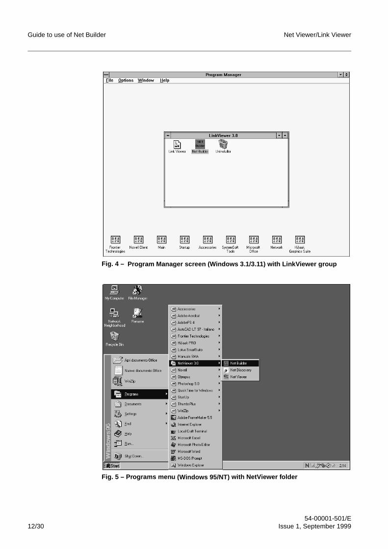
Guide to use of Net Builder Net Viewer/Link Viewer
54-00001-501/E12/30 Issue 1, September 1999
Fig. 4 – Program Mana ger screen (Windows 3.1/3.11 ) with LinkViewer grou p
Fig. 5 – Programs menu (Windows 95/NT ) with NetViewer folder
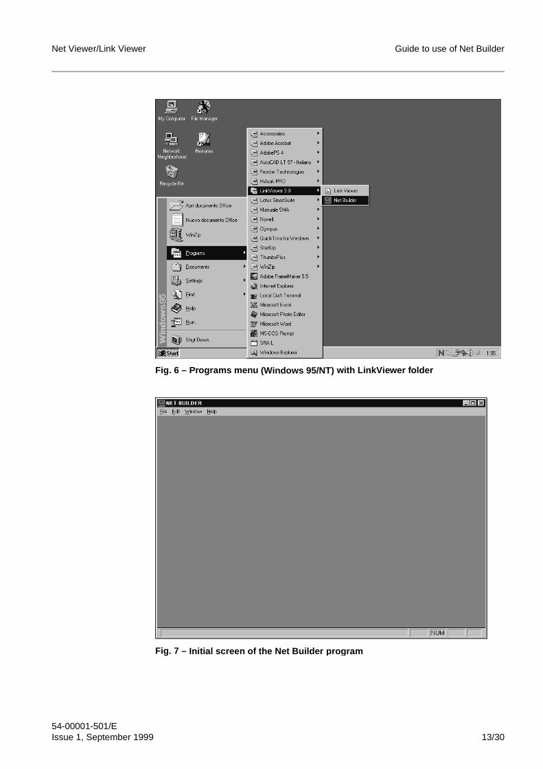
Net Viewer/Link Viewer Guide to use of Net Builder
54-00001-501/EIssue 1, September 1999 13/30
Fig. 6 – Programs menu (Windows 95/NT ) with LinkViewer folder
Fig. 7 – Initial screen of the Net Builder program
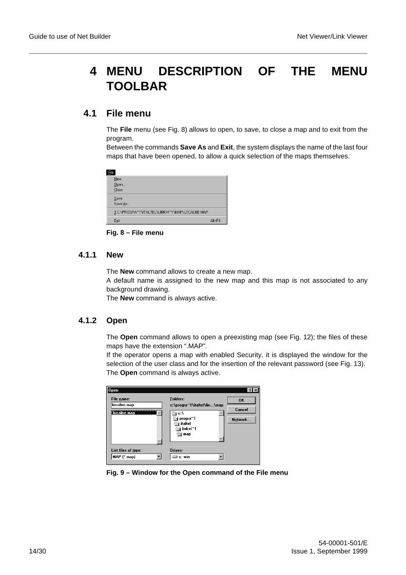
Guide to use of Net Builder Net Viewer/Link Viewer
54-00001-501/E14/30 Issue 1, September 1999
4 MENU DESCRIPTION OF THE MENUTOOLBAR
4.1 File menu
The File menu (see Fig. 8) allows to open, to save, to close a map and to exit from theprogram.Between the commands Save As and Exit , the system displays the name of the last fourmaps that have been opened, to allow a quick selection of the maps themselves.
Fig. 8 – File menu
4.1.1 New
The New command allows to create a new map.A default name is assigned to the new map and this map is not associated to anybackground drawing.The New command is always active.
4.1.2 Open
The Open command allows to open a preexisting map (see Fig. 12); the files of thesemaps have the extension “.MAP”.If the operator opens a map with enabled Security, it is displayed the window for theselection of the user class and for the insertion of the relevant password (see Fig. 13).The Open command is always active.
Fig. 9 – Window for the Open command of the File menu
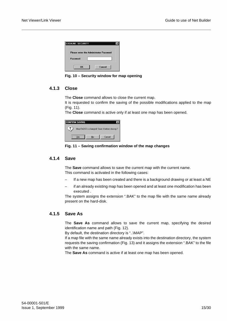
Net Viewer/Link Viewer Guide to use of Net Builder
54-00001-501/EIssue 1, September 1999 15/30
Fig. 10 – Security window for map opening
4.1.3 Close
The Close command allows to close the current map.It is requested to confirm the saving of the possible modifications applied to the map(Fig. 11).The Close command is active only if at least one map has been opened.
Fig. 11 – Saving confirmation window of the map changes
4.1.4 Save
The Save command allows to save the current map with the current name.This command is activated in the following cases:
– If a new map has been created and there is a background drawing or at least a NE
– if an already existing map has been opened and at least one modification has beenexecuted .
The system assigns the extension “.BAK” to the map file with the same name alreadypresent on the hard-disk.
4.1.5 Save As
The Save As command allows to save the current map, specifying the desiredidentification name and path (Fig. 12).By default, the destination directory is “..\MAP”.If a map file with the same name already exists into the destination directory, the systemrequests the saving confirmation (Fig. 13) and it assigns the extension “.BAK” to the filewith the same name.The Save As command is active if at least one map has been opened.
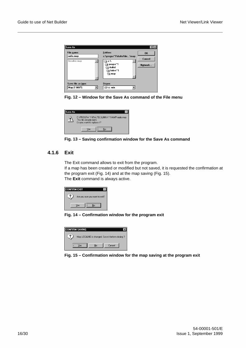
Guide to use of Net Builder Net Viewer/Link Viewer
54-00001-501/E16/30 Issue 1, September 1999
Fig. 12 – Window for the Save As command of the File menu
Fig. 13 – Savin g confirmation window for the Save As command
4.1.6 Exit
The Exit command allows to exit from the program.If a map has been created or modified but not saved, it is requested the confirmation atthe program exit (Fig. 14) and at the map saving (Fig. 15).The Exit command is always active.
Fig. 14 – Confirmation window for the program exit
Fig. 15 – Confirmation window for the map saving at the program exit
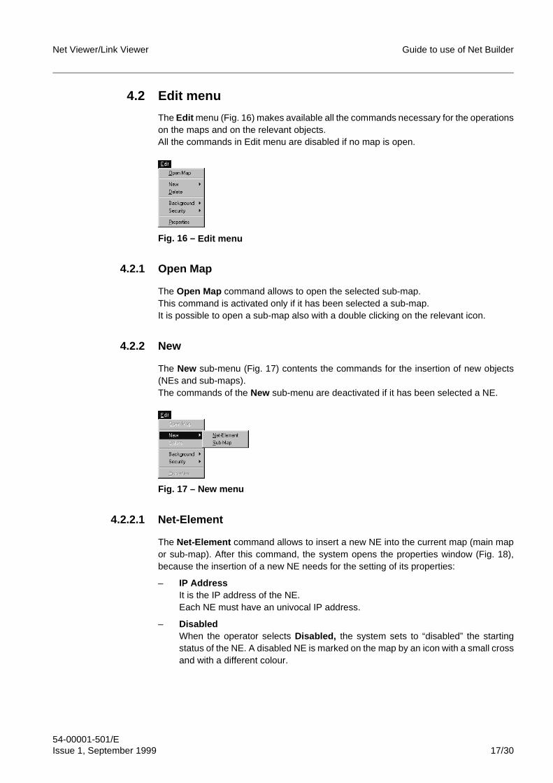
Net Viewer/Link Viewer Guide to use of Net Builder
54-00001-501/EIssue 1, September 1999 17/30
4.2 Edit menu
The Edit menu (Fig. 16) makes available all the commands necessary for the operationson the maps and on the relevant objects.All the commands in Edit menu are disabled if no map is open.
Fig. 16 – Edit menu
4.2.1 Open Map
The Open Map command allows to open the selected sub-map.This command is activated only if it has been selected a sub-map.It is possible to open a sub-map also with a double clicking on the relevant icon.
4.2.2 New
The New sub-menu (Fig. 17) contents the commands for the insertion of new objects(NEs and sub-maps).The commands of the New sub-menu are deactivated if it has been selected a NE.
Fig. 17 – New menu
4.2.2.1 Net-Element
The Net-Element command allows to insert a new NE into the current map (main mapor sub-map). After this command, the system opens the properties window (Fig. 18),because the insertion of a new NE needs for the setting of its properties:
– IP AddressIt is the IP address of the NE.Each NE must have an univocal IP address.
– DisabledWhen the operator selects Disabled, the system sets to “disabled” the startingstatus of the NE. A disabled NE is marked on the map by an icon with a small crossand with a different colour.
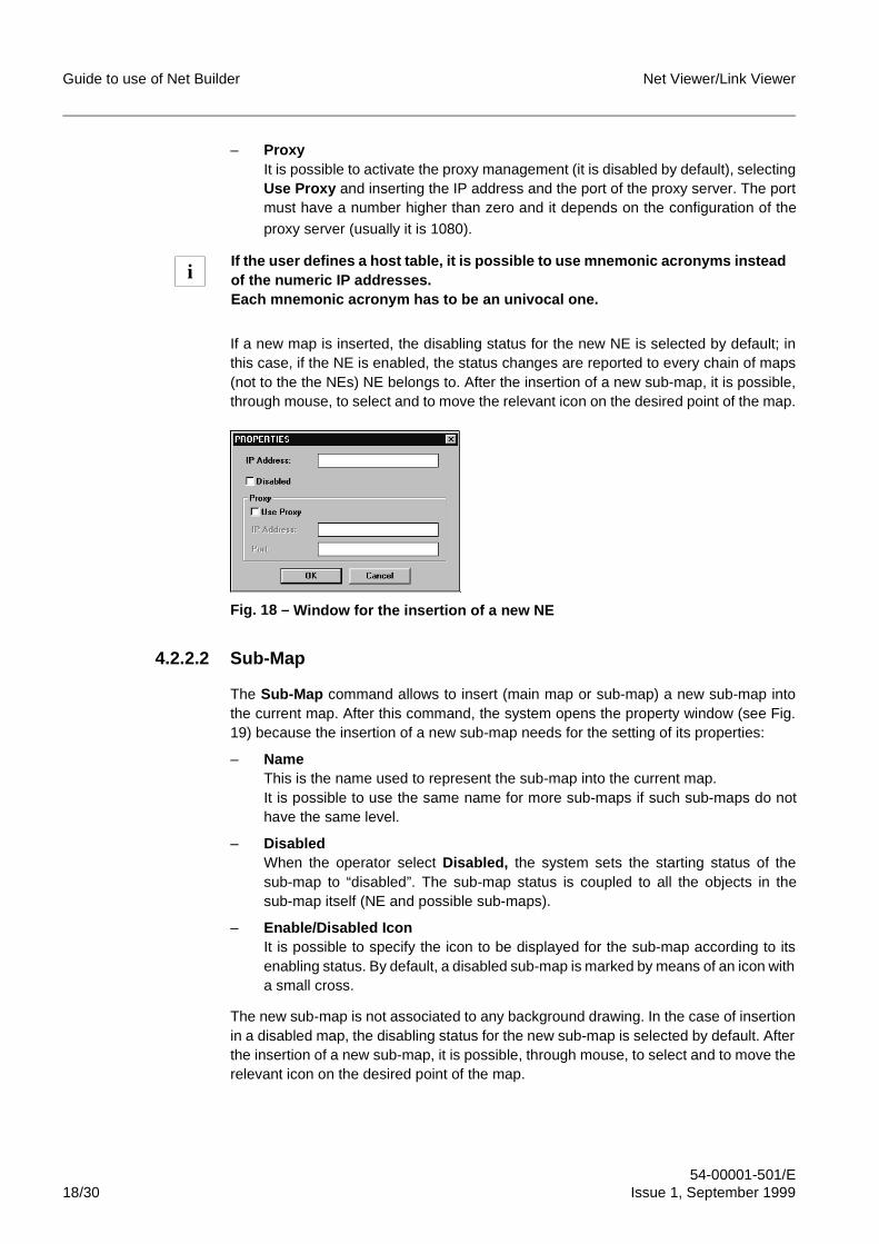
Guide to use of Net Builder Net Viewer/Link Viewer
54-00001-501/E18/30 Issue 1, September 1999
– ProxyIt is possible to activate the proxy management (it is disabled by default), selectingUse Proxy and inserting the IP address and the port of the proxy server. The portmust have a number higher than zero and it depends on the configuration of the
proxy server (usually it is 1080).
If a new map is inserted, the disabling status for the new NE is selected by default; inthis case, if the NE is enabled, the status changes are reported to every chain of maps(not to the the NEs) NE belongs to. After the insertion of a new sub-map, it is possible,through mouse, to select and to move the relevant icon on the desired point of the map.
Fig. 18 – Window for the insertion of a new NE
4.2.2.2 Sub-Map
The Sub-Map command allows to insert (main map or sub-map) a new sub-map intothe current map. After this command, the system opens the property window (see Fig.19) because the insertion of a new sub-map needs for the setting of its properties:
– NameThis is the name used to represent the sub-map into the current map.It is possible to use the same name for more sub-maps if such sub-maps do nothave the same level.
– DisabledWhen the operator select Disabled, the system sets the starting status of thesub-map to “disabled”. The sub-map status is coupled to all the objects in thesub-map itself (NE and possible sub-maps).
– Enable/Disabled IconIt is possible to specify the icon to be displayed for the sub-map according to itsenabling status. By default, a disabled sub-map is marked by means of an icon witha small cross.
The new sub-map is not associated to any background drawing. In the case of insertionin a disabled map, the disabling status for the new sub-map is selected by default. Afterthe insertion of a new sub-map, it is possible, through mouse, to select and to move therelevant icon on the desired point of the map.
If the user defines a host table, it is possible to use mnemonic acronyms insteadof the numeric IP addresses.Each mnemonic acronym has to be an univocal one.
i
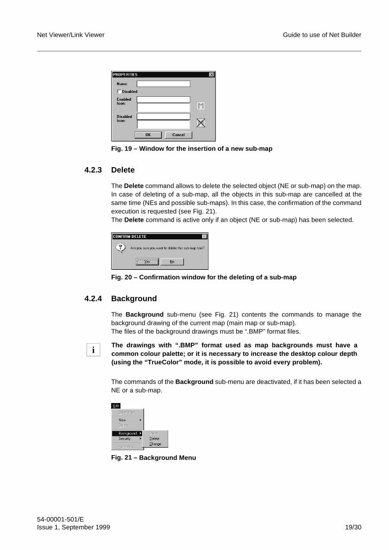
Net Viewer/Link Viewer Guide to use of Net Builder
54-00001-501/EIssue 1, September 1999 19/30
Fig. 19 – Window for the insertion of a new sub-map
4.2.3 Delete
The Delete command allows to delete the selected object (NE or sub-map) on the map.In case of deleting of a sub-map, all the objects in this sub-map are cancelled at thesame time (NEs and possible sub-maps). In this case, the confirmation of the commandexecution is requested (see Fig. 21).The Delete command is active only if an object (NE or sub-map) has been selected.
Fig. 20 – Confirmation window for the deleting of a sub-map
4.2.4 Background
The Background sub-menu (see Fig. 21) contents the commands to manage thebackground drawing of the current map (main map or sub-map).The files of the background drawings must be “.BMP” format files.
The commands of the Background sub-menu are deactivated, if it has been selected aNE or a sub-map.
Fig. 21 – Back ground Menu
The drawings with “.BMP” format used as map backgrounds must have acommon colour palette; or it is necessary to increase the desktop colour depth(using the “TrueColor” mode, it is possible to avoid every problem).
i
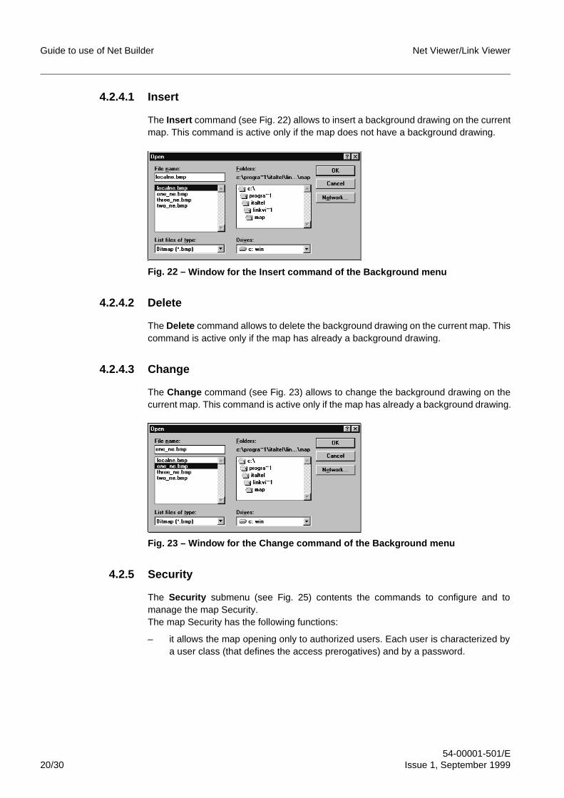
Guide to use of Net Builder Net Viewer/Link Viewer
54-00001-501/E20/30 Issue 1, September 1999
4.2.4.1 Insert
The Insert command (see Fig. 22) allows to insert a background drawing on the currentmap. This command is active only if the map does not have a background drawing.
Fig. 22 – Window for the Insert command of the Back ground menu
4.2.4.2 Delete
The Delete command allows to delete the background drawing on the current map. Thiscommand is active only if the map has already a background drawing.
4.2.4.3 Change
The Change command (see Fig. 23) allows to change the background drawing on thecurrent map. This command is active only if the map has already a background drawing.
Fig. 23 – Window for the Change command of the Background menu
4.2.5 Security
The Security submenu (see Fig. 25) contents the commands to configure and tomanage the map Security.The map Security has the following functions:
– it allows the map opening only to authorized users. Each user is characterized bya user class (that defines the access prerogatives) and by a password.
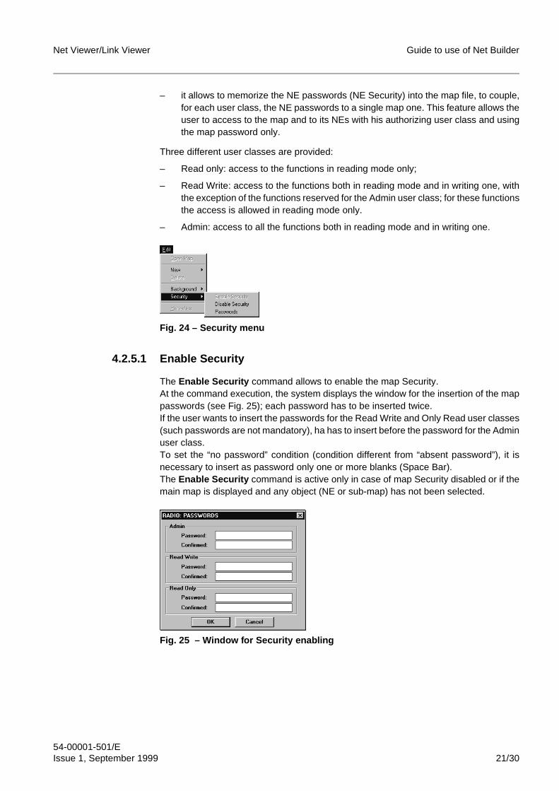
Net Viewer/Link Viewer Guide to use of Net Builder
54-00001-501/EIssue 1, September 1999 21/30
– it allows to memorize the NE passwords (NE Security) into the map file, to couple,for each user class, the NE passwords to a single map one. This feature allows theuser to access to the map and to its NEs with his authorizing user class and usingthe map password only.
Three different user classes are provided:
– Read only: access to the functions in reading mode only;
– Read Write: access to the functions both in reading mode and in writing one, withthe exception of the functions reserved for the Admin user class; for these functionsthe access is allowed in reading mode only.
– Admin: access to all the functions both in reading mode and in writing one.
Fig. 24 – Security menu
4.2.5.1 Enable Security
The Enable Security command allows to enable the map Security.At the command execution, the system displays the window for the insertion of the mappasswords (see Fig. 25); each password has to be inserted twice.If the user wants to insert the passwords for the Read Write and Only Read user classes(such passwords are not mandatory), ha has to insert before the password for the Adminuser class.To set the “no password” condition (condition different from “absent password”), it isnecessary to insert as password only one or more blanks (Space Bar).The Enable Security command is active only in case of map Security disabled or if themain map is displayed and any object (NE or sub-map) has not been selected.
Fig. 25 – Window for Security enabling
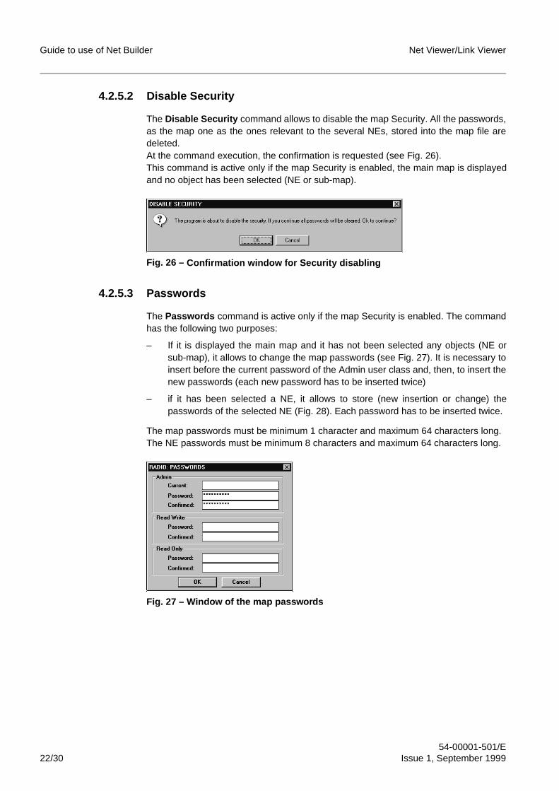
Guide to use of Net Builder Net Viewer/Link Viewer
54-00001-501/E22/30 Issue 1, September 1999
4.2.5.2 Disable Security
The Disable Security command allows to disable the map Security. All the passwords,as the map one as the ones relevant to the several NEs, stored into the map file aredeleted.At the command execution, the confirmation is requested (see Fig. 26).This command is active only if the map Security is enabled, the main map is displayedand no object has been selected (NE or sub-map).
Fig. 26 – Confirmation window for Securit y disablin g
4.2.5.3 Passwords
The Passwords command is active only if the map Security is enabled. The commandhas the following two purposes:
– If it is displayed the main map and it has not been selected any objects (NE orsub-map), it allows to change the map passwords (see Fig. 27). It is necessary toinsert before the current password of the Admin user class and, then, to insert thenew passwords (each new password has to be inserted twice)
– if it has been selected a NE, it allows to store (new insertion or change) thepasswords of the selected NE (Fig. 28). Each password has to be inserted twice.
The map passwords must be minimum 1 character and maximum 64 characters long.The NE passwords must be minimum 8 characters and maximum 64 characters long.
Fig. 27 – Window of the map passwords
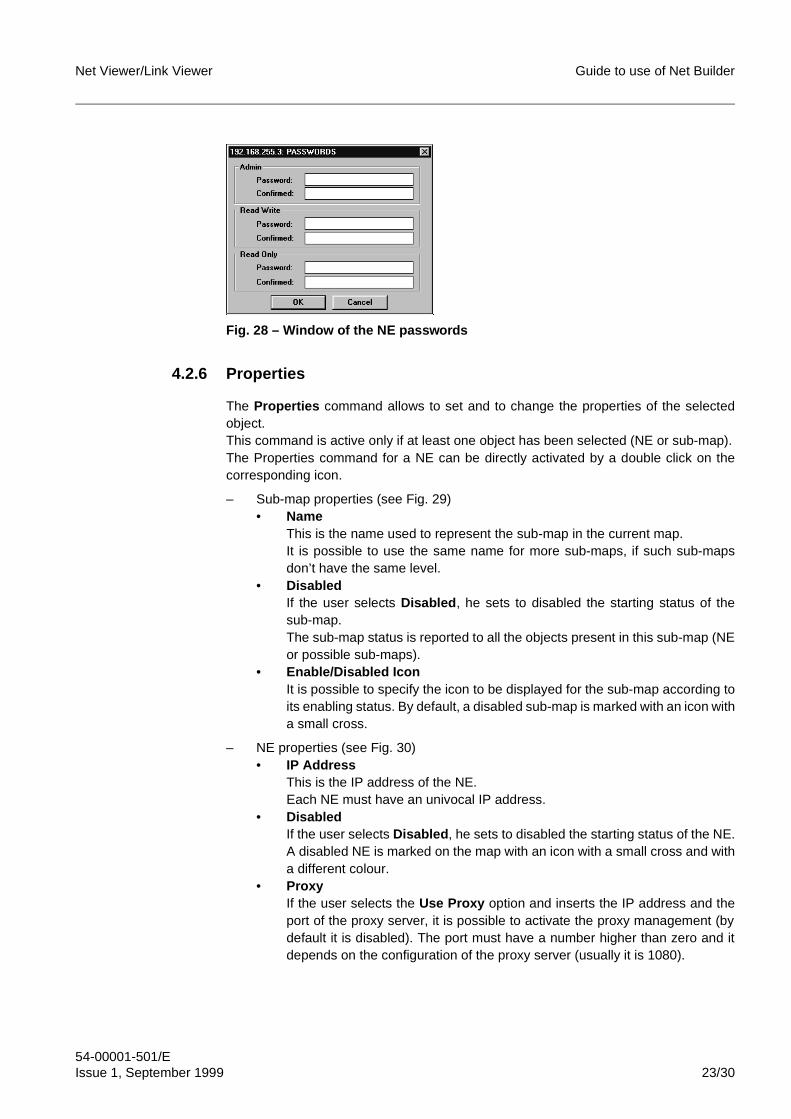
Net Viewer/Link Viewer Guide to use of Net Builder
54-00001-501/EIssue 1, September 1999 23/30
Fig. 28 – Window of the NE passwords
4.2.6 Properties
The Properties command allows to set and to change the properties of the selectedobject.This command is active only if at least one object has been selected (NE or sub-map).The Properties command for a NE can be directly activated by a double click on thecorresponding icon.
– Sub-map properties (see Fig. 29)• Name
This is the name used to represent the sub-map in the current map.It is possible to use the same name for more sub-maps, if such sub-mapsdon’t have the same level.
• DisabledIf the user selects Disabled , he sets to disabled the starting status of thesub-map.The sub-map status is reported to all the objects present in this sub-map (NEor possible sub-maps).
• Enable/Disabled IconIt is possible to specify the icon to be displayed for the sub-map according toits enabling status. By default, a disabled sub-map is marked with an icon witha small cross.
– NE properties (see Fig. 30)• IP Address
This is the IP address of the NE.Each NE must have an univocal IP address.
• DisabledIf the user selects Disabled , he sets to disabled the starting status of the NE.A disabled NE is marked on the map with an icon with a small cross and witha different colour.
• ProxyIf the user selects the Use Proxy option and inserts the IP address and theport of the proxy server, it is possible to activate the proxy management (bydefault it is disabled). The port must have a number higher than zero and itdepends on the configuration of the proxy server (usually it is 1080).
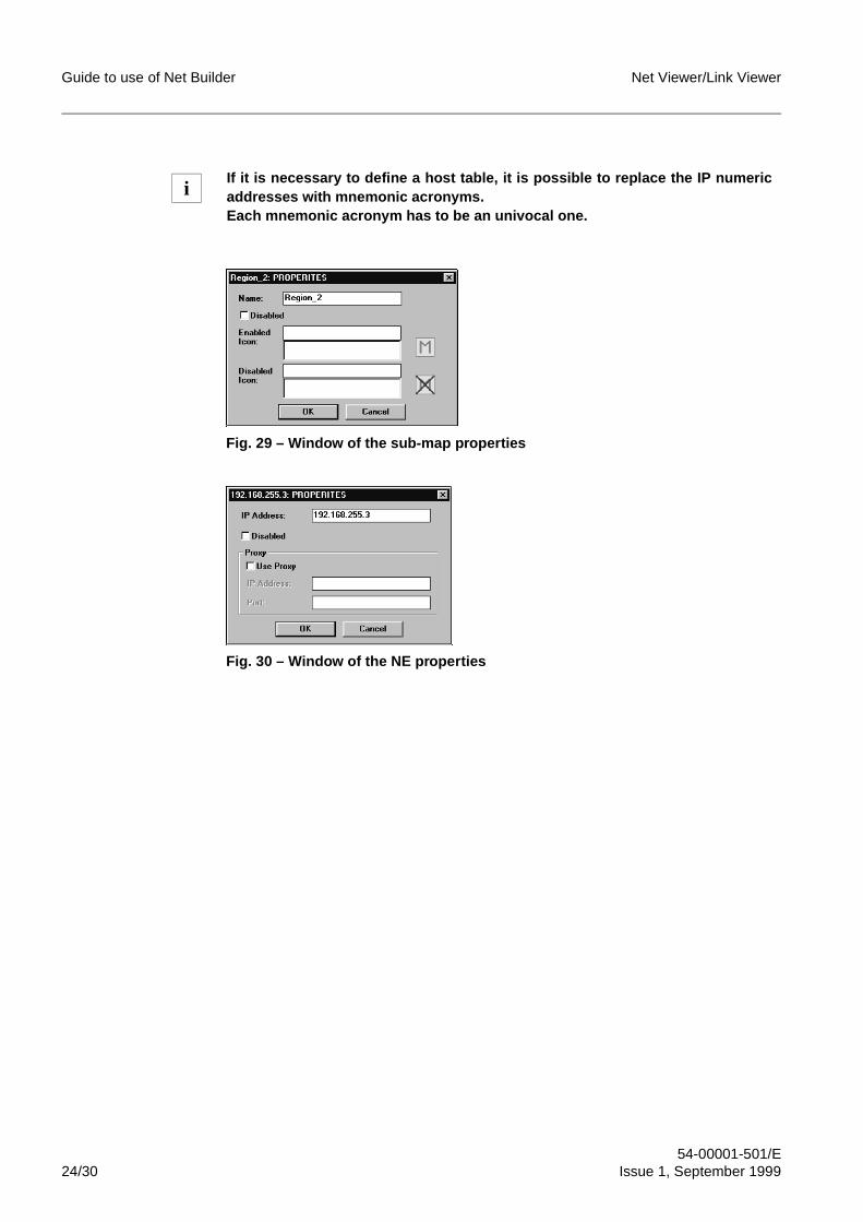
Guide to use of Net Builder Net Viewer/Link Viewer
54-00001-501/E24/30 Issue 1, September 1999
Fig. 29 – Window of the sub-map properties
Fig. 30 – Window of the NE properties
If it is necessary to define a host table, it is possible to replace the IP numericaddresses with mnemonic acronyms.Each mnemonic acronym has to be an univocal one.
i
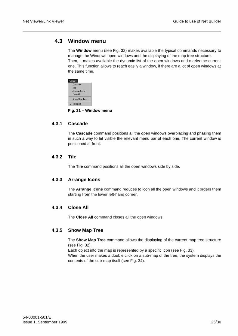
Net Viewer/Link Viewer Guide to use of Net Builder
54-00001-501/EIssue 1, September 1999 25/30
4.3 Window menu
The Window menu (see Fig. 32) makes available the typical commands necessary tomanage the Windows open windows and the displaying of the map tree structure.Then, it makes available the dynamic list of the open windows and marks the currentone. This function allows to reach easily a window, if there are a lot of open windows atthe same time.
Fig. 31 – Window menu
4.3.1 Cascade
The Cascade command positions all the open windows overplacing and phasing themin such a way to let visible the relevant menu bar of each one. The current window ispositioned at front.
4.3.2 Tile
The Tile command positions all the open windows side by side.
4.3.3 Arrange Icons
The Arrange Icons command reduces to icon all the open windows and it orders themstarting from the lower left-hand corner.
4.3.4 Close All
The Close All command closes all the open windows.
4.3.5 Show Map Tree
The Show Map Tree command allows the displaying of the current map tree structure(see Fig. 32).Each object into the map is represented by a specific icon (see Fig. 33).When the user makes a double click on a sub-map of the tree, the system displays thecontents of the sub-map itself (see Fig. 34).
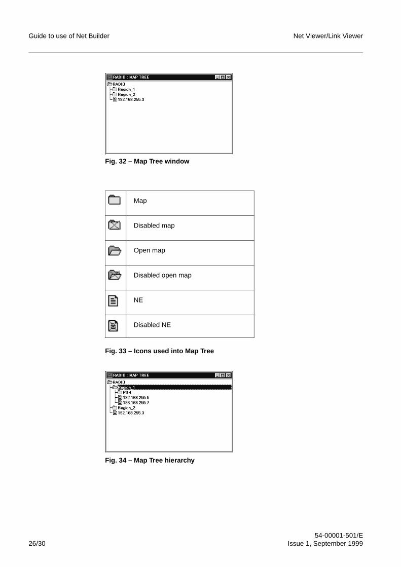
Guide to use of Net Builder Net Viewer/Link Viewer
54-00001-501/E26/30 Issue 1, September 1999
Fig. 32 – Map Tree window
Fig. 33 – Icons used into Map Tree
Fig. 34 – Map Tree hierarchy
Map
Disabled map
Open map
Disabled open map
NE
Disabled NE
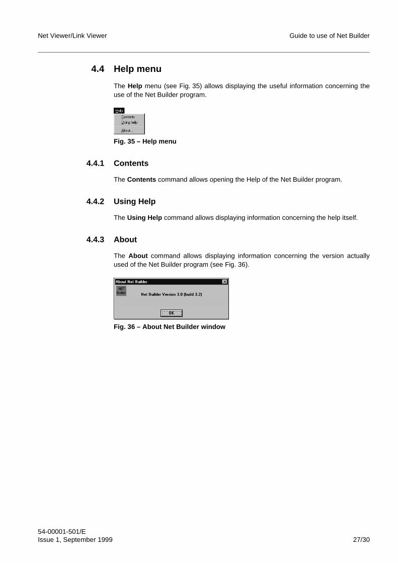
Net Viewer/Link Viewer Guide to use of Net Builder
54-00001-501/EIssue 1, September 1999 27/30
4.4 Help menu
The Help menu (see Fig. 35) allows displaying the useful information concerning theuse of the Net Builder program.
Fig. 35 – Help menu
4.4.1 Contents
The Contents command allows opening the Help of the Net Builder program.
4.4.2 Using Help
The Using Help command allows displaying information concerning the help itself.
4.4.3 About
The About command allows displaying information concerning the version actuallyused of the Net Builder program (see Fig. 36).
Fig. 36 – About Net Builder window
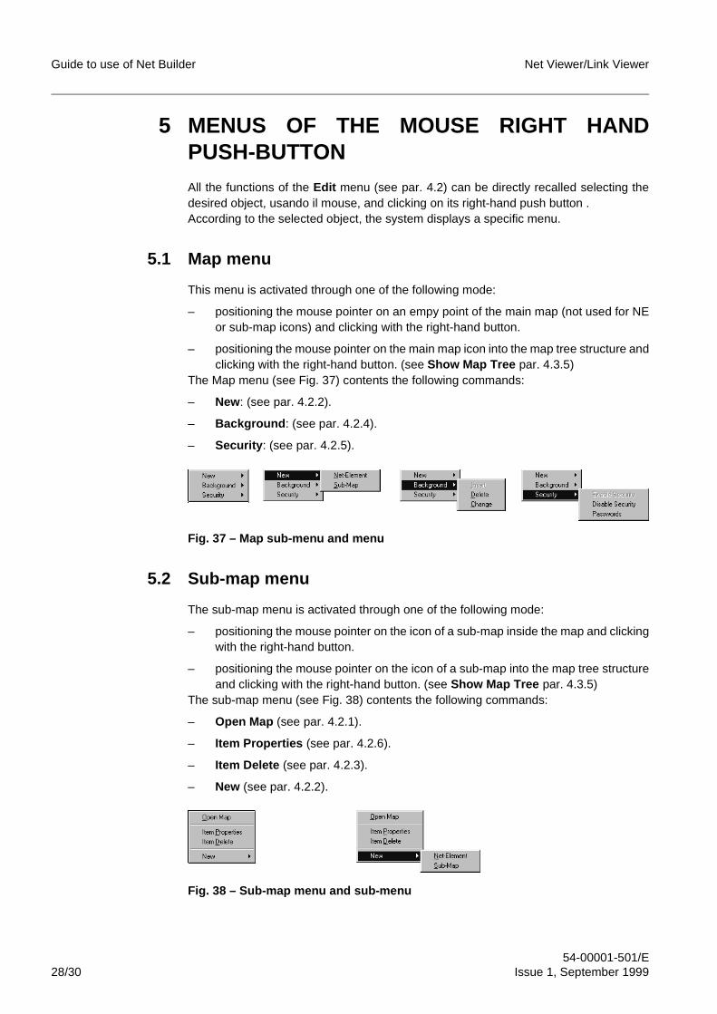
Guide to use of Net Builder Net Viewer/Link Viewer
54-00001-501/E28/30 Issue 1, September 1999
5 MENUS OF THE MOUSE RIGHT HANDPUSH-BUTTONAll the functions of the Edit menu (see par. 4.2) can be directly recalled selecting thedesired object, usando il mouse, and clicking on its right-hand push button .According to the selected object, the system displays a specific menu.
5.1 Map menu
This menu is activated through one of the following mode:
– positioning the mouse pointer on an empy point of the main map (not used for NEor sub-map icons) and clicking with the right-hand button.
– positioning the mouse pointer on the main map icon into the map tree structure andclicking with the right-hand button. (see Show Map Tree par. 4.3.5)
The Map menu (see Fig. 37) contents the following commands:
– New: (see par. 4.2.2).
– Background : (see par. 4.2.4).
– Security : (see par. 4.2.5).
Fig. 37 – Map sub-menu and menu
5.2 Sub-map menu
The sub-map menu is activated through one of the following mode:
– positioning the mouse pointer on the icon of a sub-map inside the map and clickingwith the right-hand button.
– positioning the mouse pointer on the icon of a sub-map into the map tree structureand clicking with the right-hand button. (see Show Map Tree par. 4.3.5)
The sub-map menu (see Fig. 38) contents the following commands:
– Open Map (see par. 4.2.1).
– Item Properties (see par. 4.2.6).
– Item Delete (see par. 4.2.3).
– New (see par. 4.2.2).
Fig. 38 – Sub-map menu and sub-menu
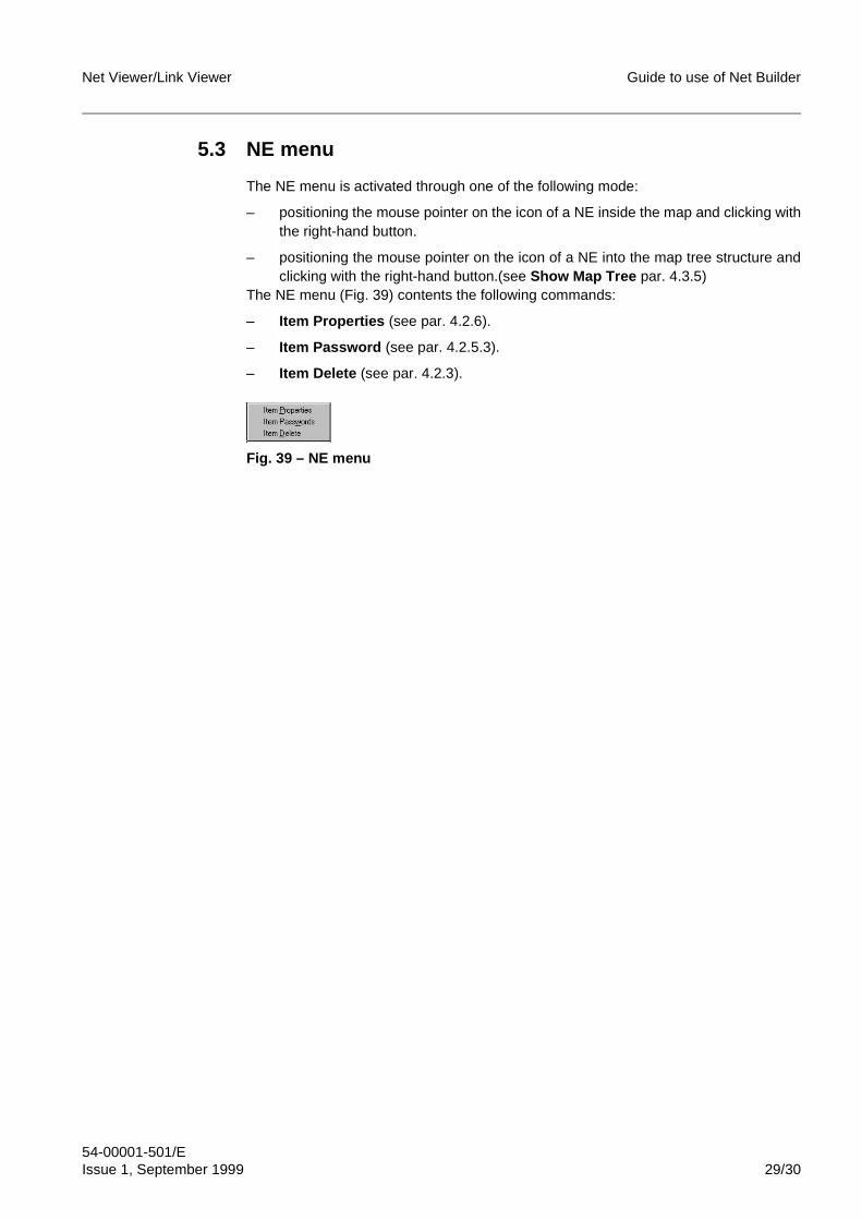
Net Viewer/Link Viewer Guide to use of Net Builder
54-00001-501/EIssue 1, September 1999 29/30
5.3 NE menu
The NE menu is activated through one of the following mode:
– positioning the mouse pointer on the icon of a NE inside the map and clicking withthe right-hand button.
– positioning the mouse pointer on the icon of a NE into the map tree structure andclicking with the right-hand button.(see Show Map Tree par. 4.3.5)
The NE menu (Fig. 39) contents the following commands:
– Item Properties (see par. 4.2.6).
– Item Password (see par. 4.2.5.3).
– Item Delete (see par. 4.2.3).
Fig. 39 – NE menu
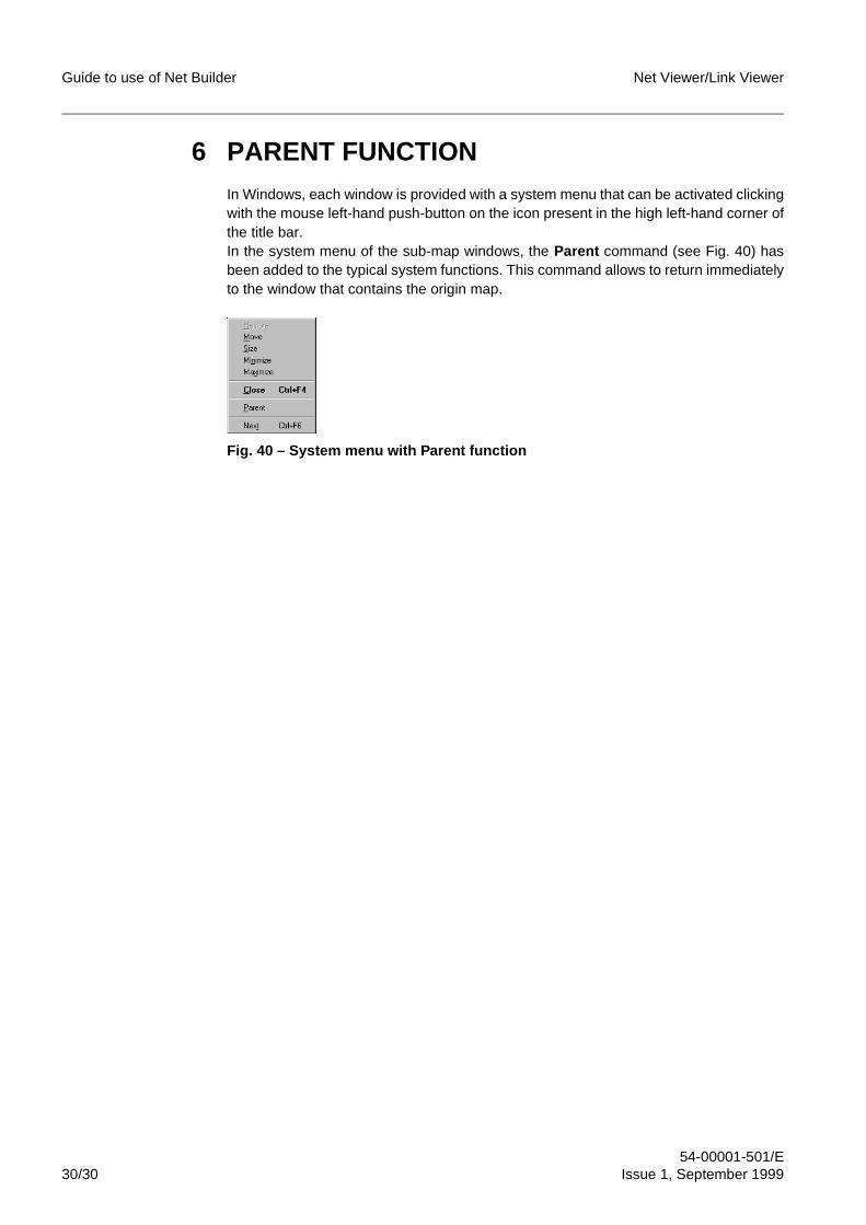
Guide to use of Net Builder Net Viewer/Link Viewer
54-00001-501/E30/30 Issue 1, September 1999
6 PARENT FUNCTIONIn Windows, each window is provided with a system menu that can be activated clickingwith the mouse left-hand push-button on the icon present in the high left-hand corner ofthe title bar.In the system menu of the sub-map windows, the Parent command (see Fig. 40) hasbeen added to the typical system functions. This command allows to return immediatelyto the window that contains the origin map.
Fig. 40 – System menu with Parent function
FINE
SRA L - Link ViewerLow capacity digital radio system
Abbreviations
53-011A2-151/EIssue 1, September 1999

Abbreviations SRA L - Link Viewer
53-011A2-151/E2/6 Issue 1, September 1999
BLANK PAGE
SRA L - Link Viewer Abbreviations
53-011A2-151/EIssue 1, September 1999 3/6
Contents
1 LIST OF ABBREVIATIONS . . . . . . . . . . . . . . . . . . . . . . . . . . . . . . . . . . . . . 4

Abbreviations SRA L - Link Viewer
53-011A2-151/E4/6 Issue 1, September 1999
1 LIST OF ABBREVIATIONS
A/D-RPT Add/Drop Repeater
ACSE Association Control Service Element
AT Asynchronous Transfer
CDC Carrier Detection Control
CMIS Common Management Information Services
CSMA/CD Carrier Sense Multiple Access/Collision Detect
DCE Data Communication Equipment
DTE Data Terminal Ready
DTR Data Terminal Equipment
EIA Electronics Industry Association
FD Frequency Diversity
FTP File Transfer Protocol
GND Ground (massa)
H/S Hot-Standby
HW Hardware
IANA Internet Assigned Numbers Authority
ID Identifier
IEEE Institute of Electrical and Electronics Engineers
IDU Indoor Unit
IF Intermediate Frequency
IN Input
IP Internet Protocol
ISO International Organisation for Standardization
ITMN Installation Test Manual
I/O Input/Output
LAN Local Area Network
LLC Logical Link Control
MAC Media Access Control
NE Network Element
NT Network
ODU Outdoor Unit
OMN Operating Manual
OSI Open System Interconnection
OUT Output
PC Personal Computer
SRA L - Link Viewer Abbreviations
53-011A2-151/EIssue 1, September 1999 5/6
PDH Plesiochronous Digital Hierarchy
PPP Point to Point Protocol
RAS Remote Access Service
RF Radio Frequency
RIP Routing Information Control
ROSE Remote Operation Service Element
RRAS Routing and Remote Access Service
RX Reception
R/O Read Only
R/W Read/Write
SDH Synchronous Digital Hierarchy
SLIP Single Link Internet Protocol
SMTP Simple Mail Transfer Protocol
SNMP Simple Network Management Protocol
SRA L Low capacity digital radio system
SVR Software Version Release
SW Software
TCP Transmission Control Protocol
TMN Telecommunications Management Network
TX Transmission

Abbreviations SRA L - Link Viewer
53-011A2-151/E6/6 Issue 1, September 1999
FINE
BLANK PAGE


PRINTED in ITALY