liquefation
DESCRIPTION
During the recent Bhuj earthquake on 26 January 2001, a number of medium to high rise residential buildings collapsed in Ahmedabad city, which is located about 300 km away from the epicenter. The city is founded over thick recent unconsolidated sediments. The severe damages in this location are attributed to the response of such unconsolidated sediments to violent shaking. This catastrophic earthquake has provided a serious reminder that liquefaction of sandy soils and sands with non-plastic fines as a result of earthquake ground shaking poses a major threat to the safety of civil engineering structures. Investigations to evaluate the liquefaction potential of soil deposits during earthquakes have been the subject of attention in recent years.TRANSCRIPT

Liquefation
CONTENTS
1.1 Introduction 1
1.2 Soil Liquefaction 1
1.3 Failure Mechanism causing Liquefaction 4
1.4 Factors Affecting Liquefaction 6
1.5 Evaluation of Liquefaction Potential by cyclic shear stress 8
1.6 Evaluation of Liquefaction Potential by Standard 10
Penetration Resistance
1.7 Measures to reduce Liquefaction of soils 14
1.8 Conclusion 15
References
1.1 INTRODUCTION:-
General :-
During the recent Bhuj earthquake on 26 January 2001, a number of medium to high rise
residential buildings collapsed in Ahmedabad city, which is located about 300 km away
from the epicenter. The city is founded over thick recent unconsolidated sediments. The
severe damages in this location are attributed to the response of such unconsolidated
1

sediments to violent shaking. This catastrophic earthquake has provided a serious
reminder that liquefaction of sandy soils and sands with non-plastic fines as a result of
earthquake ground shaking poses a major threat to the safety of civil engineering
structures. Investigations to evaluate the liquefaction potential of soil deposits during
earthquakes have been the subject of attention in recent years.
Liquefaction is a phenomenon in which the strength and stiffness of a soil is reduced by
earthquake shaking or other rapid loading. Liquefaction and related phenomena have
been responsible for tremendous amounts of damage in historical earthquakes around the
world.
Liquefaction occurs in saturated soils, that is, soils in which the space between individual
particles is completely filled with water. This water exerts a pressure on the soil particles
that influences how tightly the particles themselves are pressed together. Prior to an
earthquake, the water pressure is relatively low. However, earthquake shaking can cause
the water pressure to increase to the point where the soil particles can readily move with
respect to each other.
1.2 Soil Liquefaction:-
During heavy ground shaking by earthquakes, liquefaction occurs when the pressure
exerted by the water present in saturated soil becomes so great that the soil particles
become ‘suspended’ in the water. A soil deposit that is liquefied behaves like the better-
known phenomena: quicksand. The most commonly used terms in liquefaction include
a) Saturated soils: soils in which the space (voids) between the soil particles is
completely filled with water.
b) Pore water pressure: pressure exerted on particles of soil by the water in the
voids. Most of the time this pressure is relatively low (hydrostatic) and results
in an equilibrium condition of effective stress state. However, there are some
circumstances in which rapidly increased stresses can cause the pore water
pressure to increase.
2

In more technical terms, liquefaction is imminent when the porewater pressure (u) equals
the total overburden stress (VO). This creates an effective stress state equal to zero
VO' = [VO – u] = 0
Due to the forces exerted by gravity, soil particles naturally rest upon each other and,
depending on the properties of the soil, form sort of grid that is relatively stable (or can
be made so by compaction or other construction practices). During liquefaction the water
pressures become high enough to counteract the gravitational pull on the soil particles
and effectively ‘float’, or suspend, the particles. The soil particles can then move freely
with respect to each other. Since the soil is no longer behaving as an inactive grid of
particles, the strength and stiffness of a liquefied soil is significantly decreased, often
resulting in a variety of structural failures. (Plate 1 shows overturned apartment buildings
in Niigata, Japan due to liquefaction in 1964. Plate 2 shows an example of lateral spread
failure due an earthquake in Kobe, Japan in 1995.)
Typically when liquefaction is discussed due to a seismic event, addressing “cyclic
liquefaction” is important, this occurs when repeated cycles of shearing generate an
accumulation of pore water pressures. However, if the soil is very loose sand, “flow
liquefaction” can occur from first time loading during site development. Also, “quasi
liquefaction” describes a state of partial liquefaction of a soil deposit that does not
3
Plate 1: Nigata, Japan, 1964 Plate 2: Kobe, Japan, 1995

propagate fully throughout the site; however the subsurface liquefaction response still
negatively affects structures at the surface.
If liquefaction occurs beneath a surface that has hardened as a result of compaction,
weathering, or some other process; ‘sand boiling’ can occur. The water pressures build
below the surface to the point that the water breaks through the solid surface much like a
bubble in boiling water.
On the US West Coast, these sand boils are normally
about one to three feet in diameter (0.3 to 1 meter), plate
3 shows such a phenomena. In the New Madrid Seismic
Zone, the level of sand liquefaction was so extensive that
the sand boils in this region are called “sand blows” since
they generally are 10 to 100 feet diameter (3 to 30
meters), plate 4.
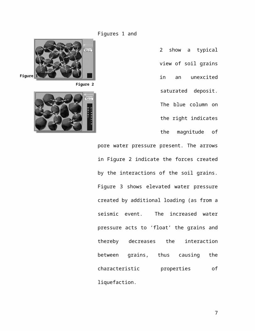
Figures 1 and
2 show a typical view of soil
grains in an unexcited
saturated
deposit. The blue column on the right indicates the
magnitude of pore water pressure present. The arrows in
Figure 2 indicate the forces created by the interactions of
the soil grains. Figure 3 shows elevated water pressure
4
Plate 4: New Madrid Seismic Zone
Plate3: Olympia, Washington, 2001
Figure 1

created by additional
loading (as from a seismic
event. The increased water
pressure acts to ‘float’ the grains and thereby decreases the
interaction between grains,
thus causing the
characteristic properties of
liquefaction.
1.3 Failure Mechanisms causing Liquefaction:-
The term liquefaction has actually been used to describe a number of related phenomena.
Because the phenomena can have similar effects, it can be difficult to distinguish between
them. The mechanisms causing them, however, are different. These phenomena can be
divided into two main categories: flow liquefaction and cyclic mobility.
Flow Liquefaction:-
Flow liquefaction is a phenomenon in which the static equilibrium is destroyed by static
or dynamic loads in a soil deposit with low residual strength. Residual strength is the
strength of a liquefied soil. New buildings on a slope that exert additional forces on the
soil beneath the foundations can apply static loading, for example. Earthquakes, blasting,
and pile driving are all example of dynamic loads that could trigger flow liquefaction.
Once triggered, the strength of a soil susceptible to flow liquefaction is no longer
sufficient to withstand the static stresses that were acting on the soil before the
disturbance.
5
Figure 2
Figure 3

Cyclic Mobility:-
Cyclic
mobility is a
liquefaction
phenomenon,
triggered by
cyclic
loading, occurring in soil deposits with static shear
stresses
lower than the soil
strength.
Deformations due to cyclic mobility develop
incrementally
because of static and
dynamic stresses that exist during an earthquake. Lateral spreading, a common result of
cyclic mobility, can occur on gently sloping and on flat ground close to rivers and lakes.
The 1976 Guatemala earthquake caused lateral spreading along the Motagua River.
Observe the cracks parallel to the river in plate 5.
On level ground, the high pore water pressure caused by
liquefaction can cause pore water to flow rapidly to the
6
Strain softening behaviour Strain hardening behaviour
Flow liquefaction Cyclic softening
Monotonic/cyclic trigger Size and duration of cyclic loading
Gravitational stresses > undrained shear strength
Shear stress reversal No shear stress reversal
Contained deformation
Uncontained deformation
Cyclic liquefaction
Cyclic mobility
Potential for progressive failure
Large deformations
Small deformations
Deformation can continue after the trigger event
Deformations essentially stop after cyclic loading
Flow chart for liquefaction (Robertson, 1994)
Plate 6: El Centro earthquake
Material characterization
Plate 5: Motagua River
ground surface. This flow can occur both during and after an earthquake. If the flowing
pore water rises quickly enough, it can carry sand particles through cracks up to the
surface, where they are deposited in the form of sand volcanoes or sand boils. These
features can often be observed at sites that have been affected by liquefaction, such as in
the field along Hwy 98 during the 1979 El Centro earthquake shown in plate 6.
1.4 Factors Affecting Liquefaction:-
1. Soil type:-
Liquefaction occurs in cohesionless soils as they lose their strength completely under
vibration due to the development of pore pressures which in turn reduce the effective
stress to zero. Liquefaction does not occur in case of cohesive soils. Only highly sensitive
clays may loose their strength substantially under vibration.
2. Grain Size and Its Distribution:-
Fine and uniform sands are more prone to liquefaction than coarser ones. Since the
permeability of coarse sand is greater than fine sand, the pore pressure developed during
vibration can dissipate faster.
3. Initial Relative Density:-
It is one of the most important factors controlling liquefaction. Both pore pressures and
settlement are considerably reduced during vibrations with increase in initial relative
density and hence chances of liquefaction and excessive settlement reduce with increased
relative density.
4. Vibration Characteristics:-
Out of the four parameters of dynamic load namely (i) frequency ;( ii) amplitude ;( iii)
acceleration; and (iv) velocity; frequency and acceleration are more important. Frequency
of the dynamic load plays vital role only if it is close to the natural frequency of the
system. Further the liquefaction depends on the type of the dynamic load i.e. whether it is
a transient load or the load causing steady vibrations.
7

Whole stratum gets liquefied at the same time under transient loading, while it may
proceed from top to lower layers under steady state vibrations (Florin and Ivanov, 1961).
For a given acceleration, liquefaction occurs only after a certain number of cycles
imparted to the deposit. Further, horizontal vibrations have more severe effect than
vertical vibrations. Multi directional shaking is more severe than one directional loading
(Seed et al., 1977), as the pore water pressure build up is much faster and the stress ratio
required is about 10 percent less than that required for unidirectional shaking.
5. Location of Drainage and Extent of Deposit:-
Sands are more pervious than fine-grained soil. However, if an impervious deposit has
large dimensions, the drainage path increases and the deposit may behave as undrained,
thereby, increasing the chances of liquefaction of such a deposit. The drainage path is
reduced by the introduction of drains made out of highly pervious material.
6. Surcharge Load:-
If the surcharge load, i.e., the initial effective stress is large, then transfer of stress from
soil grains to pore water will require higher intensity vibrations or vibrations for longer
duration. If the initial stress condition is not isotropic as in field, then stress condition
causing liquefaction depends upon Ko (coefficient of earth pressure at rest) and for Ko >5,
the stress condition required to cause liquefaction increases by at least 50%.
7. Method of Soil Formation:-
Sands unlike clays do not exhibit a characteristics structure. But recent investigations
show that liquefaction characteristics of saturated sands under cyclic loading are
significantly influenced by method of sample preparation and by soil structure.
8. Period under Sustained Load:-
Age of sand deposit may influence its liquefaction characteristics. A 75% increase in
liquefaction resistance has been reported on liquefaction of an undisturbed sand
compared to freshly prepared sample which may due to some form of cementation or
8

welding at contact points of sand particles and associated with secondary compression of
soil.
9. Previous Strain History:-
Studies on liquefaction characteristics of freshly deposited sand and of similar deposit
previously subjected to some strain history reveal, that although the prior strain history
caused no significant change in the density of the sand, it increased the stress that causes
liquefaction by factor of 1.5.
10. Trapped Air:-
If air is trapped in saturated soil and pore pressure develops, a part of it is dissipated due
to the compression of air. Hence, trapped air helps to reduce the possibility to
liquefaction.
1.5 Evaluation of Liquefaction Potential by Cyclic Shear Stress:-
Evaluation of the potential for liquefaction to occur is accomplished by comparing
equivalent measures of earthquake loading and liquefaction resistance. The most
common approach for characterization of earthquake loading is through the use of cyclic
shear stresses. By normalizing the cyclic shear stress amplitude by the initial effective
vertical stress, a cyclic stress ratio (CSR) can represent the level of loading induced at
different depths in a soil profile by an earthquake. There are different procedures for
evaluating the cyclic shear stresses - site response analyses may be performed or a
"simplified" approach may be used to estimate CSR as a function of peak ground surface
acceleration amplitude.
9

Fig 4: CSR versus N or qc
Liquefaction resistance is most commonly characterized on the basis of observed field
performance. Detailed investigation of actual earthquake case histories has allowed
determination of the combinations of insitu properties (usually SPT or CPT resistance)
and CSR for each case history. By plotting the CSR- (N1) 60 (or CSR-qc) pairs for cases
in which liquefaction was and was not been observed, a curve that bounds the conditions
at which liquefaction has historically been observed can be drawn. This curve, when
interpreted as the maximum CSR for which liquefaction of a soil with a given penetration
resistance can resist liquefaction, can be thought of as a curve of cyclic resistance ratio
(CRR). Then, the potential for liquefaction can be evaluated by comparing the earthquake
loading (CSR) with the liquefaction resistance (CRR) - this is usually expressed as a
factor of safety against liquefaction,
FS = CRR / CSR
A factor of safety greater than one indicates that the liquefaction resistance exceeds the
earthquake loading, and therefore liquefaction would not be expected.
CSR, is Estimated by SEED and IDRISS (1971) based on the maximum ground surface
acceleration (amax) at the site
CSR= τav/σ′vo = 0.65(MWF) (amax/g) (σvo / σ′vo)*rd
Where:
τav = average cyclic shear stress
MWF = Magnitude Weighting Factor = (M)2.56 /173
M = earthquake magnitude, commonly M= 7.5
10

amax = maximum horizontal acceleration at ground surface
g = acceleration due gravity = 9.81m/s2
σvo = total vertical overburden stress
σ′vo = effective vertical overburden stress
z = depth in meters (for z>25m)
rd = stress reduction factor, typically (1-0.015z)
CRR can be evaluated by Laboratory and field tests such as:
1. Cyclic Triaxial test
2. Hollow cylindrical torsion test
3. cyclic simple shear test
4. Standard penetration test
5. Cone penetration test (CPT)
6. Piezo Vibrocone test
7. Siesmic cone penetration test(SCPT)
But most commonly SPT and CPT test are conducted, as they are popular.
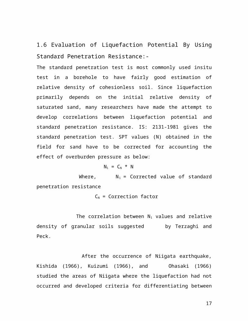
1.6 Evaluation of Liquefaction Potential By Using Standard Penetration
Resistance:-
The standard penetration test is most commonly used insitu test in a borehole to have
fairly good estimation of relative density of cohesionless soil. Since liquefaction
primarily depends on the initial relative density of saturated sand, many researchers have
made the attempt to develop correlations between liquefaction potential and standard
penetration resistance. IS: 2131-1981 gives the standard penetration test. SPT values (N)
obtained in the field for sand have to be corrected for accounting the effect of overburden
pressure as below:
N1 = CN * N
Where, N1 = Corrected value of standard penetration resistance
CN = Correction factor
The correlation between N1 values and relative density of granular soils suggested
by Terzaghi and Peck.
11

After the occurrence of Niigata earthquake, Kishida (1966), Kuizumi (1966), and
Ohasaki (1966) studied the areas of Niigata where the liquefaction had not occurred and
developed criteria for differentiating between liquefaction and nonliquefaction conditions
in that city, based on N-values of the sand deposits (Seed, 1979). The results of these
studies for Niigata are shown in the Fig 5. Ohasaki (1970) gave a useful rule of thumb
that says liquefaction is not a problem if the blow count from a standard penetration test
exceeds twice the depth in meters.
12
Standard penetration value-N
Fig 5: Relationship between the possibility of liquefaction and N values at various depths. (After Kishida, 1969).

1.7 MEASURES TO REDUCE LIQUEFACTION OF SOILS:-
General:-
There are several ways in which risk and severity of damage as a result of soil
liquefaction can be reduced. The first and most obvious is, to avoid planning
development on liquefaction susceptible soils. Besides in-situ testing, vulnerable sites
can also be identified by researching any prior events at the site. Maps showing sites of
prior liquefaction can be located from many government and research entities.
If it necessary to construct on liquefaction
susceptible soils, one can modify the design of a
structure in several ways to make the structure
more resistant damage potential from liquefaction.
A structure that incorporates ductility, has
supports that are adjustable to accommodate
differential settlement, possesses the ability to
accommodate large deformations, and has a
foundation design that can span ‘soft’ spots, can all decrease the amount of damage
incurred in the case of a liquefaction event.
Avoid Liquefaction Susceptible Soils:-
The first possibility is to avoid construction on liquefaction susceptible soils. There are
various criteria to determine the liquefaction susceptibility of a soil. By characterizing the
soil at a particular building site according to these criteria one can decide if the site is
susceptible to liquefaction and therefore unsuitable for the desired structure.
Build Liquefaction Resistant Structures:-
If it is necessary to construct on liquefaction susceptible soil because of space
restrictions, favorable location, or other reasons, it may be possible to make the structure
liquefaction resistant by designing the foundation elements to resist the effects of
liquefaction.
13
Example of foundation design that spans over a soft spot

Improve the Soil:-
The third option involves mitigation of the liquefaction hazards by improving the
strength, density, and/or drainage characteristics of the soil. This can be done using a
variety of soil improvement techniques.
Soil improvement techniques:-
The main goal of most soil improvement techniques used for reducing liquefaction
hazards is to avoid large increases in pore water pressure during earthquake shaking. This
can be achieved by densification of the soil and/or improvement of its drainage capacity.
Vibroflotation:-
Vibroflotation involves the use of a vibrating probe that
can penetrate granular soil to depths of over 100 feet. The
vibrations of the probe cause the grain structure to
collapse thereby densifying the soil surrounding the
probe. To treat an area of potentially liquefiable soil, the
vibroflot is raised and lowered in a grid pattern. Vibro
Replacement is a combination of vibroflotation with a
gravel backfill resulting in stone columns, which not only
increases the amount of densification, but also provides a
degree of reinforcement and a potentially effective means of drainage.
Dynamic Compaction:-
Densification by dynamic compaction is performed by
dropping a heavy weight of steel or concrete in a grid
pattern from heights of 30 to 100 ft. It provides an
economical way of improving soil for mitigation of
liquefaction hazards. Local liquefaction can be initiated
beneath the drop point making it easier for the sand
grains to densify. When the excess pore water pressure from the dynamic loading
14

dissipates, additional densification occurs. As illustrated in the photograph, however, the
process is somewhat invasive; the surface of the soil may require shallow compaction
with possible addition of granular fill following dynamic compaction.
Stone Columns:-
Stone columns are columns of gravel constructed in the ground. Stone columns can be
constructed by the vibroflotation method. They can also be installed in other ways, for
example, with help of a steel casing and a drop hammer as in the Franki Method. In this
approach the steel casing is driven in to the soil and gravel is filled in from the top and
tamped with a drop hammer as the steel casing is successively withdrawn.
Compaction Piles:-
Installing compaction piles is a very effective way of improving soil. Compaction piles
are usually made of prestressed concrete or timber. Installation of compaction piles both
densifies and reinforces the soil. The piles are generally installed in a grid pattern and are
generally driven to depth of up to 60 ft.
Compaction Grouting:-
Compaction grouting is a technique whereby a slow-
flowing water/sand/cement mix is injected under pressure
into a granular soil. The grout forms a bulb that displaces
and hence densifies, the surrounding soil. Compaction
grouting is a good option if the foundation of an existing
building requires improvement, since it is possible to inject the
grout from the side or at an inclined angle to reach beneath the
building.
15

1.8 Conclusions:-
i. Because liquefaction only occurs in saturated soil, its effects are most commonly
observed in low-lying areas near bodies of water such as rivers, lakes, bays, and
oceans.
ii. Cyclic shear stress to initiate liquefaction was higher than the cyclic shear stress
induced by the earthquake.
iii. Sands were considered to be the only type of soil susceptible to liquefaction, but
liquefaction was also observed in gravel and silt.
iv. Soil of medium to fine texture that is clay, silty clay, loam, and gravelly soils with
well to moderate drainage has no liquefaction vulnerability.
v. Soil of medium coarse texture that is very fine sandy loam, sandy loam with well to
moderate drainage has 50% liquefaction vulnerability.
vi. Soil of coarse texture that is sand, and loamy sand with well to moderate drainage
has 70% liquefaction vulnerability and imperfect drainage has 90% liquefaction
vulnerability.
vii. The SPT- and the CPT-based liquefaction assessment charts are the preferred means
of evaluating liquefaction potential .
viii. They are most reliable because they are supported by large databases on the
occurrence of liquefaction .
ix. The SPT test provides soil samples for identification of soil type and many
empirical design procedures are based on the SPT, N.
x. The CPT provides the best picture of soil stratification and is the most reliable
penetration test. Many design procedures are also based on CPT data .
xi. If the CPT is run with a seismic cone, the shear wave velocities can be measured at
the same time. The shear moduli can be readily obtained from the velocity data and
can be used as input into dynamic and static analyses.
16
REFERENCES
1. Kramer Steven., Text Book of Geotechnical Earthquake
Engineering.
2. Dr. Swami Saran., Text Book of Soil Dynamics And Machine Foundation.
3. Hans F.Winterkorn and Hsai-Yang Fang., ‘Foundation Engineering
Handbook’.
4. T.Lunne, P.K.Robertson and J.J.M.Powell., ‘Cone Penetration Testing in
Geotechnical Practice’.
5. T.G.Sitharam, L.GovindaRaju and A. Sridharan (2004).,‘Dynamic properties
and liquefaction potential of soils’, Special Section:Geotechnics and
Earthquake Hazards, Current Science, Vol.87,No.10,25 November 2004.
6. Alisha Kaplan (2004), ‘Soil Liquefaction’ Undergraduate Research, Mid-
America Earthquake Center and Georgia Institute of Technology, May 2004.
7. www.google.com .
17

18