liquid chiller grasso fx p duo - gea engineering for a ... documents/grasso chiller fx pduo/l... ·...
TRANSCRIPT

Liquid Chiller Grasso FX P duo
Product Information (Translation of the original text)L_501011_2
COPYRIGHTAll Rights reserved.No part of this publication may be copied or pub-lished by means of printing, photocopying, microfilmor otherwise without prior written consent of
• GEA Refrigeration Germany GmbHherein after called manufacturer. This restrictionalso applies to the corresponding drawings and dia-grams.
LEGAL NOTICEThis documentation has been written in all con-science. However, the manufacturer cannot be heldresponsible, neither for any errors occurring in thisdocumentation nor for their consequences.
Product Information |Liquid Chiller Grasso FX P duo
2 GEA Refrigeration Germany GmbH | L_501011_2 | Generated 23.01.2015

SYMBOLS USED IN THIS MANUALDanger!
Stands for an immediate danger whichleads to heavy physical injuries or tothe death.
Warning!
Stands for a possibly dangerous situa-tion which leads to heavy physicalinjuries or to the death.
Caution!
Stands for a possibly dangerous situa-tion which could lead to light physicalinjuries or to damages to property.
Hint!
Stands for an important tip whoseattention is important for the designa-ted use and function of the device.
Product Information |Liquid Chiller Grasso FX P duo
GEA Refrigeration Germany GmbH | L_501011_2 | Generated 23.01.2015 3

Product Information |Liquid Chiller Grasso FX P duo
4 GEA Refrigeration Germany GmbH | L_501011_2 | Generated 23.01.2015
TABLE OF CONTENTS1 PRODUCT NAME 9
1.1 Product designation Chiller with screw compressor, ranges FX, MX with SPduo 92 DESCRIPTION OF DESIGN AND FUNCTION 12
2.1 Design, applications 122.2 Function and Design - FX P duo Small (PP, LP, VP 2x200 duo ... 2x350 duo) 13
2.2.1 Design of the chiller 132.2.2 Process flow diagram 14
2.3 Function and Design - FX P duo Medium (PP, LP, VP 2x450 duo ... 2x900 duo) 162.3.1 Design of the Ammonia liquid Chiller 162.3.2 Process flow diagram 17
2.4 Function and Design - FX P duo Large (PP, LP, VP 2x1190 duo ... 2x2400 duo) 192.4.1 Design of the Ammonia liquid Chiller 19
2.4.1.1 Series PP 202.4.1.2 Series PP, LP, VP 20
2.4.2 Process flow diagram 212.5 Refrigerant circuit 222.6 Oil System 23
2.6.1 Oil separation 232.6.2 Oil Cooling 232.6.3 Oil filter (integrated into the screw compressor) 232.6.4 Oil pump 24
2.6.4.1 Oil pump (integrated into the compressor) 242.6.4.2 External oil pump and common oil filter 24
2.6.5 Oil supply and injection oil 242.6.6 Solenoid valves - Oil supply 242.6.7 Oil circuit, miscellaneous 252.6.8 Oil return from the low pressure side 25
2.7 Safety devices 252.8 Monitoring devices 272.9 Capacity control for each screw compressor 282.10 Sequential operation 28
3 DIMENSIONS, WEIGHTS, FILL QUANTITIES AND CONNECTIONS 293.1 Series FX PP 2x200 duo ... PP 2x350 duo 293.2 Series FX PP 2x450 duo ... PP 2x900 duo 303.3 Series FX LP, VP 2x200 duo ... LP, VP 2x350 duo 313.4 Series FX LP, VP 2x450 duo ... LP, VP 2x900 duo 33
4 PERFORMANCE CHARACTERISTICS 364.1 Performance characteristics of FX PPduo Series 364.2 Performance characteristics of FX LPduo Series 374.3 Performance characteristics of FX VPduo Series 38
5 OPERATING LIMITS 406 SOUND PRESSURE 42
Product Information |Liquid Chiller Grasso FX P duo
GEA Refrigeration Germany GmbH | L_501011_2 | Generated 23.01.2015 5

Product Information |Liquid Chiller Grasso FX P duo
6 GEA Refrigeration Germany GmbH | L_501011_2 | Generated 23.01.2015

TABLE OF FIGURESfig. 1 Process flow diagram, Grasso FX Pduo Small 15fig. 2 Process flow diagram Grasso FX Pduo Medium, internal oil pump 18fig. 3 Process flow diagram Grasso FX Pduo Medium, external oil pump 19fig. 4 Process flow diagram Grasso FX Pduo Large 22fig. 5 Ammonia Liquid Chillers - Type FX PP 2x200 duo ... FX PP 2x350 duo 29fig. 6 Ammonia Liquid Chillers - Type FX PP 2x450 duo ... FX PP 2x900 duo 30fig. 7 Ammonia Liquid Chiller - Type FX LP, VP 2x200 duo ... FX LP, VP 2x350 duo 32fig. 8 Ammonia Liquid Chiller - Type FX LP, VP 2x450 duo ... FX LP, VP 2x900 duo 34
Product Information |Liquid Chiller Grasso FX P duo
GEA Refrigeration Germany GmbH | L_501011_2 | Generated 23.01.2015 7
Product Information |Liquid Chiller Grasso FX P duo
8 GEA Refrigeration Germany GmbH | L_501011_2 | Generated 23.01.2015
1 PRODUCT NAME
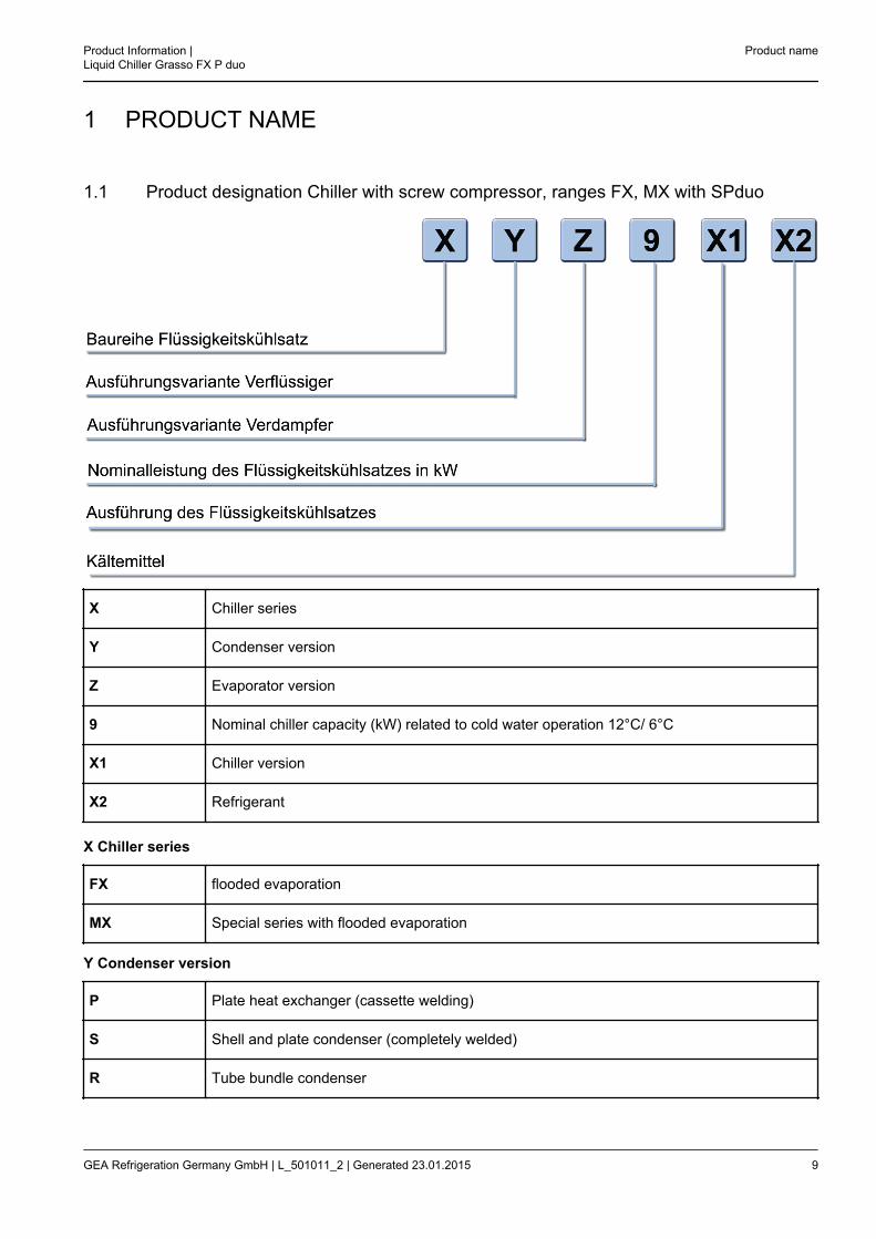
1.1 Product designation Chiller with screw compressor, ranges FX, MX with SPduo
X Chiller series
Y Condenser version
Z Evaporator version
9 Nominal chiller capacity (kW) related to cold water operation 12°C/ 6°C
X1 Chiller version
X2 Refrigerant
X Chiller series
FX flooded evaporation
MX Special series with flooded evaporation
Y Condenser version
P Plate heat exchanger (cassette welding)
S Shell and plate condenser (completely welded)
R Tube bundle condenser
Product Information |Liquid Chiller Grasso FX P duo
Product name
GEA Refrigeration Germany GmbH | L_501011_2 | Generated 23.01.2015 9

L Air cooled condenser (not in the scope of delivery for GEA Refrigeration Germany)
V Vapour condenser (not in the scope of deliver for GEA Refrigeration Germany)
Z Evaporator version
P Plate heat exchanger (cassette welding)
S Plate heat exchanger (completely welded)
R Shell and tube evaporator (flooded operation)
O Without evaporator (condenser unit)
9 Nominal chiller capacity 2940 min-1 kW related to cold water operation 12°C / 6°C
2 Compressor type Nominal capacity inkW 2 Compressor type Nominal capacity in
kW
C 2 X 200 P 2 X 800
D 2 X 250 R 2 X 1100
E 2 X 300 S 2 X 1300
G 2 X 350 T 2 X 1500
H 2 X 450 V 2 X 1700
L 2 X 550 W 2 X 2000
M 2 X 650 Y 2 X 2400
N 2 X 900
X1 design of the chiller
duo with Grasso SPduo
SB with Grasso SPduo / 1 compressor standby
2U 2 individual Grasso SP1
2USB 2 individual Grasso SP1/ 1 Grasso SP1 Standby
X2 refrigerant
NH3 Ammonia
Other refrigerants on request
Product name Product Information |Liquid Chiller Grasso FX P duo
10 GEA Refrigeration Germany GmbH | L_501011_2 | Generated 23.01.2015

Naming example
FX VP 2x900duo NH3
Chiller with screw compressor (FX)for external vapour condenser (V),with plate heat exchanger as evaporator (P),Nominal capacity 1800 kW (2x900),2 active compressors (duo),Refrigerant ammonia (NH3)
Product Information |Liquid Chiller Grasso FX P duo
Product name
GEA Refrigeration Germany GmbH | L_501011_2 | Generated 23.01.2015 11
2 DESCRIPTION OF DESIGN AND FUNCTION
2.1 Design, applications
The Standard Ammonia Liquid Chillers (ALC) Programme provides for proven components as complete refriger-ation systems for medium and large refrigeration and/or air conditioning needs.Main fields of application:
• cold water for air conditioning
• cold brine for air conditioning with combined ice storage operation
• cold water for industrial processes
• cold brine for industrial processes
• (cold) and warm water for heat pump operationGenerally, these refrigeration systems use ammonia as refrigerant which is characterized by a high regrigerationcapacity, low energy consumption and a beneficial price and which is completely neutral towards the environ-ment.Based on the screw compressor packages series Grasso SPduo, the ammonia liquid chiller programme(2x200 ... 2x900) covers a refrigerating capacity ranging from 400 to 1800 kW, related to the cold water range.The capacity ranges are determined by the 8 sizes C, D, E, G, H, L, M, N of the Grasso screw compressor ser-ies SH and MC.Always two compressors in a liquid chiller are operating in parallel on a common low-pressure system.Standby operation of one of the compressors is also possible.The liquid chiller programme 2x200...2x900 consists of three series which comprise different condenser designsand are operated with flooded evaporator systems on the basis of gravity recirculation.The ammonia liquid chillers 2x200...2x900 are of modular design and consist of the following main modules:
• Standard screw compressor unit Grasso SPduo Small or Grasso SPduo Medium
• Heat exchanger subassembly with low pressure separator and de-oiling system
• Low-voltage facility with control unit
• Optionally absorber as an additional safety deviceThe modular design of the ammonia liquid chillers 2x200 ... 2x900 is based on the standard screw compressorunits Grasso SPduo SMALL and Grasso SPduo MEDIUM which have vertical oil separators.Correspondingly, the ammonia liquid chillers 2x200 ... 2x900 are equipped with vertical liquid separators.This ensures the compact design of ammonia liquid chillers.Solely plate-type evaporators are used as evaporators.Each series is optionally fitted with a standard evaporator, but can also be adapted to specific operating condi-tions and customer requests, if need be.On the condenser side, the following versions are used:
• Plate type heat exchanger PP
• Evaporative condenser VP
• Air-cooled condenser LPAmmonia liquid chillers of performance FX PPduo are - as a general rule - delivered ready for connection, com-pletely piped and wired.
Description of Design and Function Product Information |Liquid Chiller Grasso FX P duo
12 GEA Refrigeration Germany GmbH | L_501011_2 | Generated 23.01.2015
The FX PPduo chillers are supplied complete en bloc if allowed by the shipping proportions. In the case of chill-ers, which due to their size cannot be transported as a complete unit, the prepared flanges has to be connectedon site. Therefor no welding necessary.The ammonia liquid chillers FX LPduo and FX VPduo are delivered completely so that solely the air cooled con-denser (FX LPduo) or the evaporative condenser (FX VPduo) has to be connected on site.The condenser must be professional installed by the plant engineer. Therefor definitely welding necessary.The heat exchangers of the 3 series are designed acc. to the parameters of a project on the evaporator and thecondenser side.The temperature differences are selected so as to best meet the customer's requirements.
The standard version of the liquid chillers is equipped with a freely programmable standard logic controller(PLC).All operating and fault signals as well as the process variables can be read from a display.The control devive is operated via a Touch Panel.The ALC are supplied without refrigerant and without refrigeration machine oil; they are filled with dry nitrogen ( ≥0.5 bar overpressure).Each ALC is supplied including a User's Manual comprising a description of the refrigeration cycle, a commis-sioning instruction, an operating instruction, and the maintenance instruction.Separate user manuals containing more detailed information about the screw compressors are available.
2.2 Function and Design - FX P duo Small (PP, LP, VP 2x200 duo ... 2x350 duo)
2.2.1 Design of the chiller
The chiller has a modular structure and comprises the following main components:
– The screw compressor package Grasso SPduo Small with the main component compressor, motor, oil sepa-rator, oil cooler, oil filter, oil pump, suction filter. The screw compressor package Grass SPduo Small is com-posed of 2 parallel compressors, which can be shut off separately.
– Heat exchanger assembly including evaporator, condenser, liquid separator, expansion device, oil returnsystem.
– Low voltage system with control unit.The evaporator comes standard as heat plate exchanger. In the Chiller as heat pump no evaporator is included.Various versions of the condenser are available.
Product Information |Liquid Chiller Grasso FX P duo
Description of Design and Function
GEA Refrigeration Germany GmbH | L_501011_2 | Generated 23.01.2015 13
2.2.2 Process flow diagram
Hint!
For other positions as named see customer parts list and P+I diagram.
Description of Design and Function Product Information |Liquid Chiller Grasso FX P duo
14 GEA Refrigeration Germany GmbH | L_501011_2 | Generated 23.01.2015
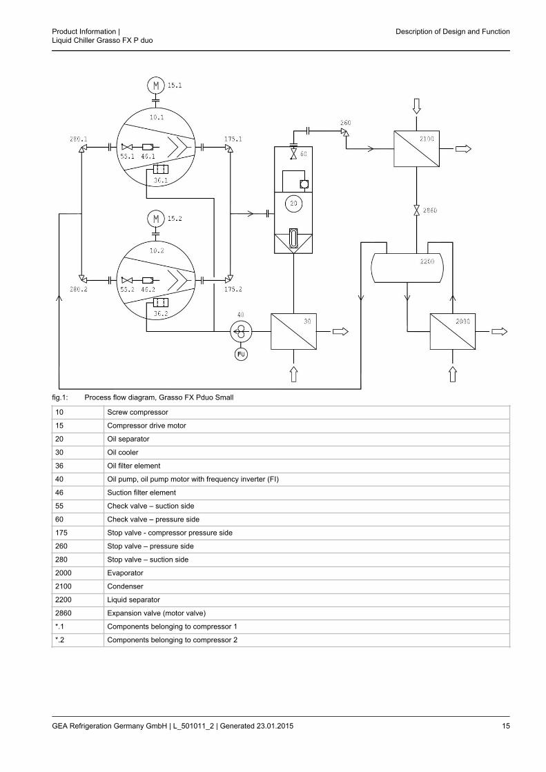
fig.1: Process flow diagram, Grasso FX Pduo Small
10 Screw compressor
15 Compressor drive motor
20 Oil separator
30 Oil cooler
36 Oil filter element
40 Oil pump, oil pump motor with frequency inverter (FI)
46 Suction filter element
55 Check valve – suction side
60 Check valve – pressure side
175 Stop valve - compressor pressure side
260 Stop valve – pressure side
280 Stop valve – suction side
2000 Evaporator
2100 Condenser
2200 Liquid separator
2860 Expansion valve (motor valve)
*.1 Components belonging to compressor 1
*.2 Components belonging to compressor 2
Product Information |Liquid Chiller Grasso FX P duo
Description of Design and Function
GEA Refrigeration Germany GmbH | L_501011_2 | Generated 23.01.2015 15
2.3 Function and Design - FX P duo Medium (PP, LP, VP 2x450 duo ... 2x900 duo)
2.3.1 Design of the Ammonia liquid Chiller
The ammonia liquid chiller has a modular structure and comprises the following main components:
• Screw compressor package DuoPack Medium with main parts screw compressor, motor, oil separator, oilcooler, oil filter, suction filter. The Grasso SPduo consists of two in parallel mode operating screw compres-sors, which are separately shutable.
• Heat exchanger subassembly including evaporator, condenser, liquid separator, expansion device, oilreturning system.
• Low voltage system with control device.Three ALC design series are offered. In all designs, plate condensers are provided as evaporators (P).
Description of Design and Function Product Information |Liquid Chiller Grasso FX P duo
16 GEA Refrigeration Germany GmbH | L_501011_2 | Generated 23.01.2015

2.3.2 Process flow diagram
The FX Pduo Medium series of chillers consists of the following main assemblies and components:
10 Screw compressors 260 Stop valve - pressure side
15 Compressor drive motor 280 Stop valve - suction side
20 Oil separator 500 Solenoid valve - function oil
35/36 Oil filter/ oil filter element 1675 Oil pressure relief valve
40 Oil pump * 2000 Evaporator
46 Suction filter element 2100 Condenser
55 Check valve - suction side 2200 Liquid separator
60 Check valve - pressure side 2250 High pressure float valve
175 Stop valve - compressor pressure side
* for external oil pump: Frequency controlled oil pump motor
Hint!
For other positions as named see customer parts list and P+I diagram.
Product Information |Liquid Chiller Grasso FX P duo
Description of Design and Function
GEA Refrigeration Germany GmbH | L_501011_2 | Generated 23.01.2015 17
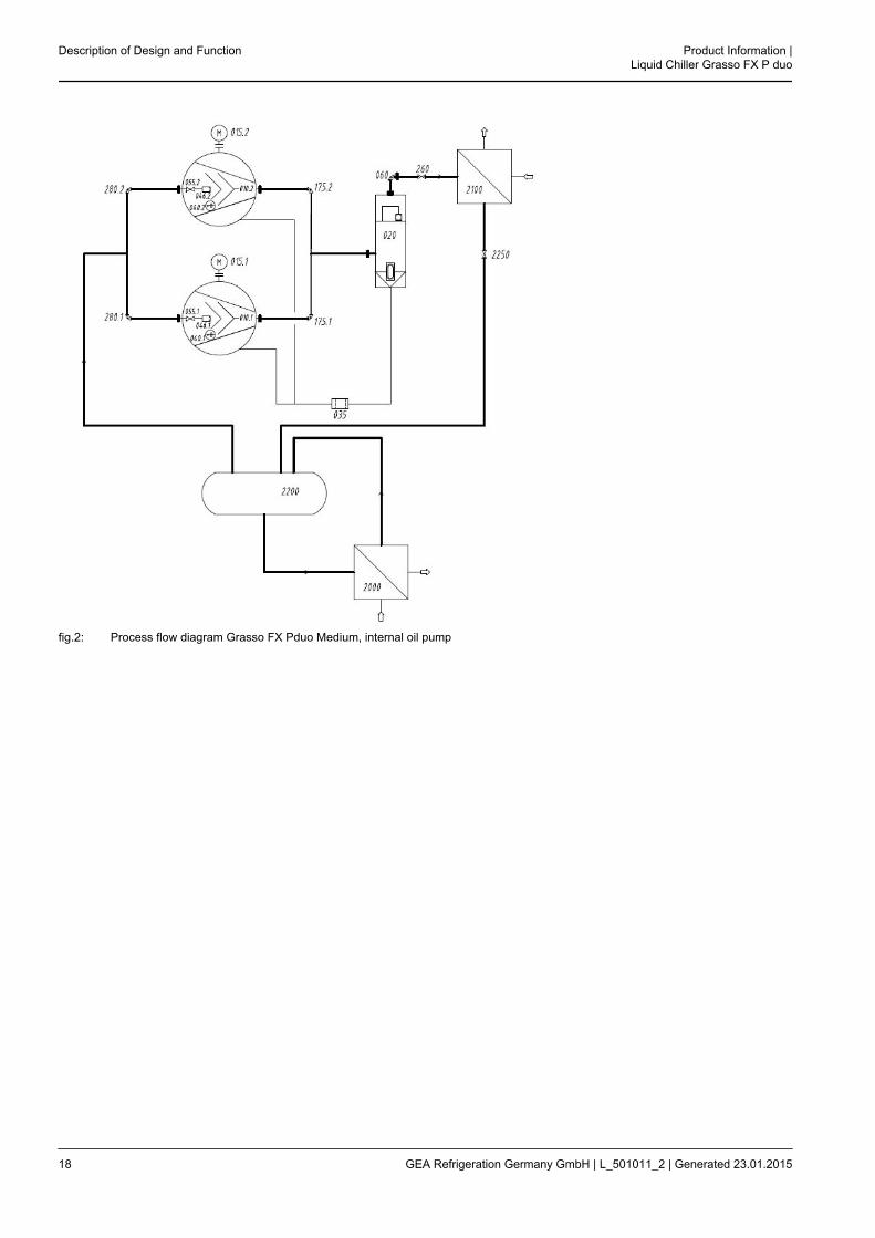
fig.2: Process flow diagram Grasso FX Pduo Medium, internal oil pump
Description of Design and Function Product Information |Liquid Chiller Grasso FX P duo
18 GEA Refrigeration Germany GmbH | L_501011_2 | Generated 23.01.2015

fig.3: Process flow diagram Grasso FX Pduo Medium, external oil pump
2.4 Function and Design - FX P duo Large (PP, LP, VP 2x1190 duo ... 2x2400 duo)
2.4.1 Design of the Ammonia liquid Chiller
The Standard Ammonia Liquid Chillers (ALC) Programme provides for proven components as complete refriger-ation systems for medium and large refrigeration and/or air conditioning needs.Generally, these refrigeration systems use ammonia as refrigerant which is characterized by a high regrigerationcapacity, low energy consumption and a beneficial price and which is completely neutral towards the environ-ment.Based on the screw compressor packages series Grasso SPduo, the ammonia liquid chiller programme(2x1100 ... 2x2400) covers a refrigerating capacity ranging from 2200 to 4800 kW, related to the cold waterrange.The performance ranges are determined by the four type sizes R, S, V, Y of the LT screw compressor series.Two screw compressors are always operating in parallel mode in the ALC.The liquid chiller programme 2x1100...2x2400 consists of three series which comprise different condenserdesigns and are operated with flooded evaporator systems on the basis of gravity recirculation.The ammonia liquid chiller has a modular structure and comprises the following main components:
• Screw compressor package Grasso SPduo Large with main parts screw compressor, motor, oil separator, oilcooler, oil filter, suction filter. The Grasso SPduo consists of two in parallel mode operating screw compres-sors, which are separately shutable.
Product Information |Liquid Chiller Grasso FX P duo
Description of Design and Function
GEA Refrigeration Germany GmbH | L_501011_2 | Generated 23.01.2015 19

• Heat exchanger subassembly including evaporator, condenser, liquid separator, expansion device, oilreturning system.
• Low voltage system with control device.The modular design of the ammonia liquid chillers 2x1100 ... 2x2400 is based on the standard screw compressorunits Grasso SPduo Large which have vertical oil separators.Correspondingly, the ammonia liquid chillers 2x1100 ... 2x2400 are equipped with vertical liquid separators.This ensures the compact design of ammonia liquid chillers.In all designs, plate condensers are provided as evaporators (P).Each series is optionally fitted with a standard evaporator, but can also be adapted to specific operating condi-tions and customer requests, if need be.On the condenser side, the following versions are used:
• Plate type heat exchanger (PP)
• Evaporative condenser (VP)
• Air-cooled condenser (LP)
2.4.1.1 Series PP
The ammonia liquid chiller PP series are supplied as a standard, ready for connection, fully piped and wired.A high pressure floating valve is used as expansion device.Standard Chiller is equipped with water cooled oil cooler.The Chiller is supplied including the condenser.The chiller is devided into two or more parts for transportation because of its large dimensions.The components must be connected on site (split installation).
2.4.1.2 Series PP, LP, VP
The heat exchangers of the 3 series are designed acc. to the parameters of a project on the evaporator and thecondenser side.The temperature differences are selected so as to best meet the customer's requirements.In the standard design, the ALC are equipped with a standard SPC Grasso System Control (GSC).A background illumination LCD display allows reading of all operating and fault messages as well as processvariables.The display is operated via a robust keypad having function and system keys.Optionally, an absorption facility can be offered for each ALC providing for additional safety in cases of accident.The use of the absorption facility depends upon the installation conditions of the ALC and the design of themachine room and ought to be checked in each individual case taking into account the relevant provisions.The ALC are supplied without refrigerant and without refrigeration machine oil; they are filled with dry nitrogen ( ≥0.5 bar overpressure).Each ALC is supplied including a User's Manual comprising a description of the refrigeration cycle, a commis-sioning instruction, an operating instruction, and the maintenance instruction.Separate user manuals containing more detailed information about the screw compressors are available.
Description of Design and Function Product Information |Liquid Chiller Grasso FX P duo
20 GEA Refrigeration Germany GmbH | L_501011_2 | Generated 23.01.2015
2.4.2 Process flow diagram
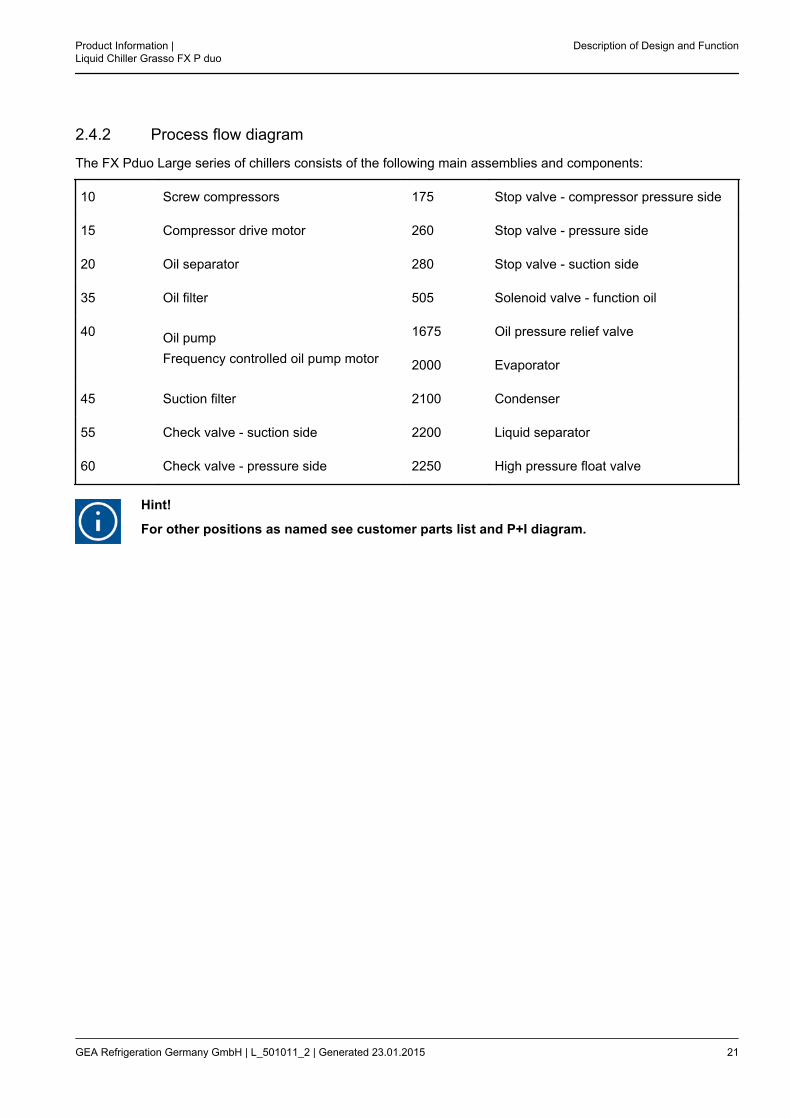
The FX Pduo Large series of chillers consists of the following main assemblies and components:
10 Screw compressors 175 Stop valve - compressor pressure side
15 Compressor drive motor 260 Stop valve - pressure side
20 Oil separator 280 Stop valve - suction side
35 Oil filter 505 Solenoid valve - function oil
40 Oil pumpFrequency controlled oil pump motor
1675 Oil pressure relief valve
2000 Evaporator
45 Suction filter 2100 Condenser
55 Check valve - suction side 2200 Liquid separator
60 Check valve - pressure side 2250 High pressure float valve
Hint!
For other positions as named see customer parts list and P+I diagram.
Product Information |Liquid Chiller Grasso FX P duo
Description of Design and Function
GEA Refrigeration Germany GmbH | L_501011_2 | Generated 23.01.2015 21
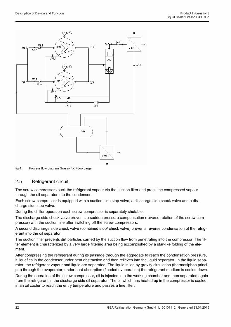
fig.4: Process flow diagram Grasso FX Pduo Large
2.5 Refrigerant circuit
The screw compressors suck the refrigerant vapour via the suction filter and press the compressed vapourthrough the oil separator into the condenser.Each screw compressor is equipped with a suction side stop valve, a discharge side check valve and a dis-charge side stop valve.During the chiller operation each screw compressor is separately shutable.The discharge side check valve prevents a sudden pressure compensation (reverse rotation of the screw com-pressor) with the suction line after switching off the screw compressors.A second discharge side check valve (combined stop/ check valve) prevents reverse condensation of the refrig-erant into the oil separator.The suction filter prevents dirt particles carried by the suction flow from penetrating into the compressor. The fil-ter element is characterized by a very large filtering area being accomplished by a star-like folding of the ele-ment.After compressing the refrigerant during its passage through the aggregate to reach the condensation pressure,it liquefies in the condenser under heat abstraction and then relieves into the liquid separator. In the liquid sepa-rator, the refrigerant vapour and liquid are separated. The liquid is led by gravity circulation (thermosiphon princi-ple) through the evaporator; under heat absorption (flooded evaporation) the refrigerant medium is cooled down.During the operation of the screw compressor, oil is injected into the working chamber and then separated againfrom the refrigerant in the discharge side oil separator. The oil which has heated up in the compressor is cooledin an oil cooler to reach the entry temperature and passes a fine filter.
Description of Design and Function Product Information |Liquid Chiller Grasso FX P duo
22 GEA Refrigeration Germany GmbH | L_501011_2 | Generated 23.01.2015

Despite the highly effective oil separation system, oil penetrates to the low pressure side of the chiller. A specialautomatic and maintenance-free oil returning system developed by GEA Refrigeration Germany GmbH returnsthe oil from the liquid separator back to the screw compressor. This is a basic precondition for fault-free opera-tion of the evaporator system.The capacity control of the screw compressor operates infinitely variable by volume flow control (internal bypass)and thus adapts optimally to the refrigeration capacity being effectively required and ranging from 100% toapprox. 15%.
2.6 Oil System
The screw compressors operate oil-flooded. During the compression process, refrigerating machine oil is sup-plied to the compressor for lubrication, sealing, noise reduction, and absorption of part of the compression heat.After the compression process, the oil is separated again from the refrigerant in the oil separator.
2.6.1 Oil separation
The refrigerant-oil mixture is led into the first part of oil separator. There, the first step of oil separation is per-formed by a combined agglomerator/ demister. At the same time, these part of the oil separator serves as oilcollector.In the second part of the oil separator, the fine separation of the aerosol oil portion from the refrigerant is per-formed by means of replaceable fine oil separation cartridges. The oil separated in the fine section of the oil sep-arator is returned to the compressor via an additional injection orifice.
2.6.2 Oil Cooling
Before it is returned to the compressor for use, the oil heated up in the compressor has to be cooled down to atemperature at which it has sufficient viscosity.The following oil coolers are available:
1. Liquid cooled (non corrosive media)
– water (non corrosive)
– propylene-glycol (25%)
– ethylene-glycol (35%)
– Other cooling media on request
2. refrigerant cooled
Hint!
The HD-receiver needed to operate the refrigerant cooled oil cooler is supplied standard andsecures the supply of the refrigerant to the oil cooler. It's size makes it unsuitable as thereceiver for the complete installation.
2.6.3 Oil filter (integrated into the screw compressor)
After cooling, the oil passes into the oil filter which holds back solid particles from the full oil flow.Thereafter, part of the oil is directly led into the rotor chamber for cooling while the other part is led to the screwcompressor for further oil supply.Due to its large surface, the star-folded glass fibre element has a high absorbing capacity and thus a long oper-ating lifetime. The relative filter fineness is 10‑15 μm.
Product Information |Liquid Chiller Grasso FX P duo
Description of Design and Function
GEA Refrigeration Germany GmbH | L_501011_2 | Generated 23.01.2015 23
2.6.4 Oil pump
Caution!
Depending upon the operating conditions, the liquid chiller set may be equipped with an inter-nal or an external oil pump.
Standard equipment: external oil pump
2.6.4.1 Oil pump (integrated into the compressor)
The internal oil pump is used only in that case, if the oil supply is quite reliable for all possible operating condi-tions.The oil pump is directly driven by the compressor and runs during the entire compressor operation.The oil pump guarantees a sufficient oil pressure for control slide adjustment.The unused oil supplied by the oil pump flows via an oil pressure control valve (spring-held check valve) to theoil supply channel in the screw compressor. The oil pressure regulating valve regulates a pressure differencebetween the discharge and suction sides of the oil pump.
2.6.4.2 External oil pump and common oil filter
ApplicationApplication: Booster or operation at low pressure ratios between suction and discharge sides.The design type external oil pumpe and external oil filter is allowed for a protected oil supply of screw compres-sors at low pressure ratios.The oil pump is driven by an electric motor and runs during the entire compressor operation.The oil pump guarantees a sufficient oil pressure for bearing and shaft seal oil supply.The oil pump motor speed control full automatic operates the difference pressure control between oil pump suc-tion and discharge sides.The into the screw compressor integrated oil pump is not applicable, an additional oil pressure relief valve is nec-essary.
2.6.5 Oil supply and injection oil
Compressor is fed with function oil from a compressor port.The injection oil is fed without a pump via the oil injection regulating valve.The oil injection control valve is used to adjust the necessary compression discharge temperature. The controlvalve is provided with a check function to prevent sucking refrigerant through the oil pump.The functional oil ensures the oil supply to the bearings, the compensation piston, and the gland.
2.6.6 Solenoid valves - Oil supply
In standard case of external oil pumps, solenoid valves are used for supplying the screw compressor with oil.The solenoid valves oil supply open in case of starting the drive motor with the screw compressor.This prevents the further oil supply and a pressure compensation between the unit suction and discharge sidesin case of stopping the unit operation or in case of control slide MIN-position.If one screw compressor operation is not required (part load operation), than the oil supply is interrupt by sole-noid valves.
Description of Design and Function Product Information |Liquid Chiller Grasso FX P duo
24 GEA Refrigeration Germany GmbH | L_501011_2 | Generated 23.01.2015
The solenoid valves are switched via the controls. Further information can be found in the controller manual.
2.6.7 Oil circuit, miscellaneous
The screw compressor package is fitted with an oil drain and refilling stop valve which may be connected to aseparate oil pump or receiver.
Internal oil pumpThe oil in oil filter may be drained for changing oil filter via a separate stop valve.Vent valves and valves for oil draining are fitted to compressor and oil filter housings for maintenance and repairpurposes.
External oil pumpA multi-function block can be flanged onto the oil filter as an oil distributor system depending on the conditions ofuse. The block takes all ??? regulating and stop valves needed for regulating the oil circuit. There is thereforeone concentrated control unit for the package.The oil filter with MF-block is fitted with an oil drain and refilling stop valve which may be connected to a separateoil pump or receiver.
2.6.8 Oil return from the low pressure side
In spite of a very good oil separation in the fine separation parts of oil separators some oil will always reach otherparts of the system. For returning the oil reaching the liquid separator there exists a special automatic oil returnsystem. The automated oil return usually works with a oil disposal basin and two solenoid valves.
1. Filling the draining tank (2300)A refrigerant-oil mixture is drained from a suitable point between the liquid separator and the evaporator andled to the draining tank. To this end, a solenoid valve (2305) is opened.
2. Evaporation of refrigerantClose the solenoid valve (2305). The possibly existing liquid refrigerant can evaporate in the drainer byabsorbing heat from the surroundings. The evaporation time is restricted by the control unit.
3. Expelling oil from the draining vesselAfter the evaporation period, hot gas is led via the solenoid valve (2310) into the draining vessel for a shortwhile and this pushes the oil into the suction nozzle of the compressor.The oil draining cycle is actuated by the control system. The control time parameters for the solenoid valvescan be set at the control panel.
In the case of high-pressure applications, both solenoid valves can be replaced by a joint motor valve.
2.7 Safety devices
The following safety devices are fitted to every standard liquid chiller:
• Safety devices to prevent the discharge pressure from being exceeded(Discharge pressure transducer 105)The compressor control device switches off the drive motor when the discharge pressure limit has beenexceeded.limit value p = see parameter listThe compressor primary slide is moving into MINIMUM direction before reaching the limit value to preventthe limit value overrange.
• stop valve - pressure transducer (100)
Product Information |Liquid Chiller Grasso FX P duo
Description of Design and Function
GEA Refrigeration Germany GmbH | L_501011_2 | Generated 23.01.2015 25

The compressor control device switches off the drive motor when the suction pressure falls below the speci-fied limit valuelimit value p = see parameter listThe compressor primary slide is moving into MINIMUM direction before reaching the limit value to preventthe limit value underrange.
• Safety device to prevent the differential pressure between oil pressure (pressure transducer 110) andthe compressor discharge pressure (pressure transducer 105) from falling too lowoil circuit monitoringfor each compressorThe compressor control device switches off the chiller when the pressure difference between oil pressureand compressor discharge pressure falls below the specified limit value.Limit value Δp ≤ 1 bar
• Safety device to prevent the final discharge temperature from being exceeded (resistance thermome-ter 120)for each compressorThe compressor control device switches off the drive motor when the discharge pressure limit has beenexceeded.Limit value t = 100°C
• Oil temperature (resistance thermometer 125)The compressor control device switches off the drive motor when the discharge pressure limit has beenexceeded.Limit value toil ≤ 70°CThe minimum oil viscosity for safe compressor operation is ≥ 7 cSt.
• Compressor drive motor safety devicescompressor drive motor (each compressor)Rated current limitation (016), which is realised by the respective compressor control. When the ratedmotor current is exceeded, the compressor capacity control slide is driven in the MIN direction until the motorcurrent reaches an allowable level. The normal output control then comes back into force.Thermistor (017) which shuts down the compressor drive motor if its winding temperature limit has beenexceeded.
• Check valve - suction side (055)for each compressorCheck valve - suction side protects the screw compressor package from a sudden pressure equalisation withthe suction line after shut down.
• Check valve - discharge side after oil separation (060)prevents refrigerant recondensing into the oil separator.
• Safety pressure limiter (350)with two separate reset locks, one of which is only resettable with a tool (see UVV VBG 20). The SafetyPressure Limiter switches off the compressor drive motor if the discharge pressure rises above the set point.Switching off pressure 1 = see parameter listSwitching off pressure 2 = see parameter listIf the liquid refrigerant can reach more than 90% of the oil separator’s volume, then the client has to installan additional saftey valve against liquid pressure in oil separator. The design is in compliance with DIN8975-7, 7.5.1.1.
• Thermostat (361) oil heater
Description of Design and Function Product Information |Liquid Chiller Grasso FX P duo
26 GEA Refrigeration Germany GmbH | L_501011_2 | Generated 23.01.2015
Set value = see parameter list
• Temperature limiter (362) oil heaterSet value = see parameter listshuts down the oil heating if a certain surface temperature is exceeded at the oil heating.
• Oil filter monitoring - pressure transducer (395)Oil filter monitoring with pressure transducer oil pressure after oil filter, which is measuring the oil pressurebehind the oil filter. The compressor control device switches off the drive motor when the differential pres-sure limit between discharge pressure and 2nd oil pressure has been exceeded.Limit value Δp ≥ 2 bar
• Overflow valve (540)protects the compressor against impermissibly high pressures.Lifting Pressure = see parameter list and R+I flow chart
Warning!
The pressure relief valve must be connected to the suction side on installing the package inthe refrigeration plant!
• Oil pressure relief valve (1675)limitates the pressure difference between the oil pump discharge side and the discharge pressure. The oilpressure relief valve is integrated into the multifunction block (Standard). It is separately mounted for specialoperating conditions with external oil filter.Set value = see parameter list and R+I flow chart
• Secondary refrigerant outlet temperature (2040)If the actual value falls below the limit value while the primary slide of the compressor is in the minimumposition, the control system switches the liquid chiller set off.
• Flow switch (2050)If the minimum refrigerant throughflow amount is not reached, the control system switches the liquid chillerset off.
2.8 Monitoring devices
The following ACTUAL values are continuously shown on the display of the compressor control panel.
® Absolute primary slide position (compressor 1 and 2)
® Temperature of secondary refrigerant (controled parameter)
® Current consumption of the motor (compressor 1 and 2)
® Oil differential pressure - oil circuit monitoring (compressor 1 and 2)
® Suction pressure
® Discharge pressure
® Oil pressure (compressor 1 and 2)
® Discharge temperature (compressor 1 and 2)
® Oil temperature
® Suction gas temperature
® Suction pressure's saturation temperature
Product Information |Liquid Chiller Grasso FX P duo
Description of Design and Function
GEA Refrigeration Germany GmbH | L_501011_2 | Generated 23.01.2015 27

® discharge pressure saturation temperature
® Operating hours of the compressor motor (compressor 1 and 2)
®
®
Hint!
For more details see "User Instruction" of the compressor control device.
2.9 Capacity control for each screw compressor
All screw compressors are equipped with continuous capacity control in the range 10-100% (the lower percent-age can vary depending on the application and conditions of use).The capacity is adjusted by shortening the screw compressor stroke. The defining factor for the compressionprocess is the effective rotor length; this is altered by a hydraulically operated control slide.The position of the control slide is recorded by the position sensor. The control device signals the attainment ofthe MIN or MAX end position and the relative control slide position can be displayed on the Touch Panel in per-cent.The hydraulic adjustment of the control slide is controlled by 4 solenoid valves (Y1 ... Y4 for Vi fixed) or by 6solenoid valves (Y1 ... Y6 for Vi variable) which are combined in one block.The control slide travel speeds in the MIN and MAX directions should be the same as much as possible duringoperation to ensure better compressor control. There are throttle screws for influencing the adjustment speed.The solenoid valves are cycled by the control device and controlled separate.
SV Y1 SV Y2 SV Y3 SV Y4
Capacity ↑ open closed closed open
Capacity ↓ closed open open closed
SV Y5 SV Y6
Capacity ↑ closed open
Full-load operation: closed open
Capacity ↓ open closed
Hint!
See installation instructions for the screw compressor
2.10 Sequential operation
The screw compressors operate load-dependent in optimized sequential mode. Energy-unfavourable controlpositions should be avoided for each separate screw compressor. The permanent forcing in case of capacitychanges effects on that compressor, which is situated in the most energy-unfavourable control position.For further information see User Instruction of control device.
Description of Design and Function Product Information |Liquid Chiller Grasso FX P duo
28 GEA Refrigeration Germany GmbH | L_501011_2 | Generated 23.01.2015

3 DIMENSIONS, WEIGHTS, FILL QUANTITIES AND CONNEC-TIONS
3.1 Series FX PP 2x200 duo ... PP 2x350 duo
The below-mentioned data Daten are valid for the following standard conditions:Temperature of secondary refrigerant + 12°C/ + 6°C and temperature of cooling medium + 27°C/ + 32°CDeviant data can be the result of other conditions.
fig.5: Ammonia Liquid Chillers - Type FX PP 2x200 duo ... FX PP 2x350 duo
1 Secondary refrigerant outlet
2 Secondary refrigerant inlet
3 Cooling medium outlet
4 Cooling medium inlet
Dimensions and weights
Chiller Type Length (mm) Width (mm) Height (mm) Weight withoutfilling (kg)
Operatingweight (kg)
PP 2x200 duo 4500 2400 2300 4900 5100
PP 2x250 duo 4500 2400 2300 5000 5200
PP 2x300 duo 4500 2400 2300 5200 5450
PP 2x350 duo 4500 2400 2300 5500 5800
Product Information |Liquid Chiller Grasso FX P duo
Dimensions, Weights, Fill quantities and Connections
GEA Refrigeration Germany GmbH | L_501011_2 | Generated 23.01.2015 29

Fill quantities, Connections, Sound pressure level
ChillerType
Oil charg-ing (dm3)
Refrigerantcharging
(kg)
Cold waterconnection
NB
Coolingwater con-nection NB
Oil coolerconnection
NB
Electricalconnec-
tions (kW)
Soundpressure
level dB(A)at a dis-tance of
1m
PP 2x200duo 90 60 100 100 1" 2x45 81
PP 2x250duo 90 65 100 100 1" 2x55 81
PP 2x300duo 90 70 100 100 1 1/2" 2x75 82
PP 2x350duo 90 75 100 100 1 1/2" 2x75 82
3.2 Series FX PP 2x450 duo ... PP 2x900 duo
The below-mentioned data Daten are valid for the following standard conditions:Temperature of secondary refrigerant + 12°C/ + 6°C and temperature of cooling medium + 27°C/ + 32°CDeviant data can be the result of other conditions.
fig.6: Ammonia Liquid Chillers - Type FX PP 2x450 duo ... FX PP 2x900 duo
1 Secondary refrigerant outlet
2 Secondary refrigerant inlet
Dimensions, Weights, Fill quantities and Connections Product Information |Liquid Chiller Grasso FX P duo
30 GEA Refrigeration Germany GmbH | L_501011_2 | Generated 23.01.2015

Dimensions and weights
Chiller Type Length (mm) Width (mm) Height (mm) Weight withoutfilling (kg)
Operatingweight (kg)
PP 2x450 duo 5800 2500 2650 9700 10000
PP 2x550 duo 6000 2750 2650 10200 10600
PP 2x650 duo 6300 3000 2800 10700 11150
PP 2x900 duo 6500 3200 2800 11500 12200
Fill quantities, Connections, Sound pressure level
ChillerType
Oil charg-ing (dm3)
Refrigerantcharging
(kg)
Cold waterconnection
NB
Coolingwater con-nection NB
Oil coolerconnection
NB
Electricalconnec-tions (kW)
Soundpressure
level dB(A)at a dis-tance of
1m
PP 2x450duo 160 110 150 150 1 1/2" 2x90 83
PP 2x550duo 160 130 150 150 1 1/2" 2x110 84
PP 2x650duo 200 150 150 150 1 1/2" 2x132 85
PP 2x900duo 200 190 150 150 1 1/2" 2x160 86
3.3 Series FX LP, VP 2x200 duo ... LP, VP 2x350 duo
The below-mentioned data Daten are valid for the following standard conditions:Secondary refrigerant temperature + 12°C/ + 6°C and condensing temperatures + 35°C (VP Series) resp.+ 45°C (LP Series)Deviant data can be the result of other conditions.
Product Information |Liquid Chiller Grasso FX P duo
Dimensions, Weights, Fill quantities and Connections
GEA Refrigeration Germany GmbH | L_501011_2 | Generated 23.01.2015 31
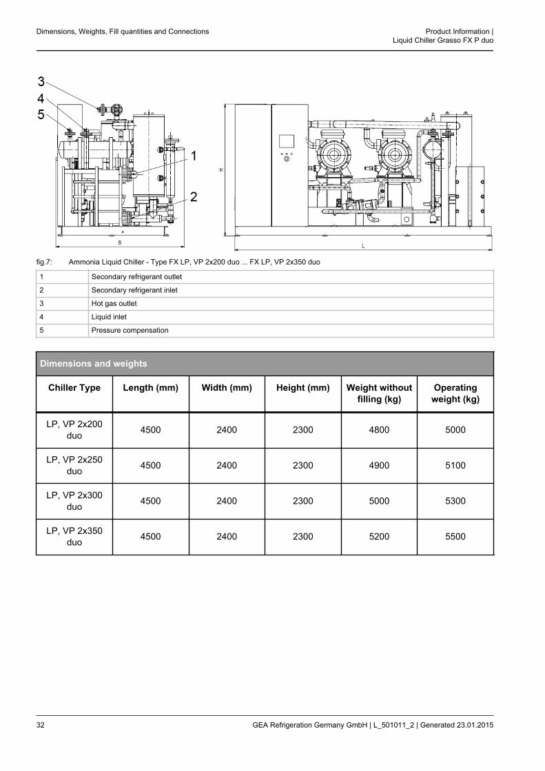
fig.7: Ammonia Liquid Chiller - Type FX LP, VP 2x200 duo ... FX LP, VP 2x350 duo
1 Secondary refrigerant outlet
2 Secondary refrigerant inlet
3 Hot gas outlet
4 Liquid inlet
5 Pressure compensation
Dimensions and weights
Chiller Type Length (mm) Width (mm) Height (mm) Weight withoutfilling (kg)
Operatingweight (kg)
LP, VP 2x200duo 4500 2400 2300 4800 5000
LP, VP 2x250duo 4500 2400 2300 4900 5100
LP, VP 2x300duo 4500 2400 2300 5000 5300
LP, VP 2x350duo 4500 2400 2300 5200 5500
Dimensions, Weights, Fill quantities and Connections Product Information |Liquid Chiller Grasso FX P duo
32 GEA Refrigeration Germany GmbH | L_501011_2 | Generated 23.01.2015
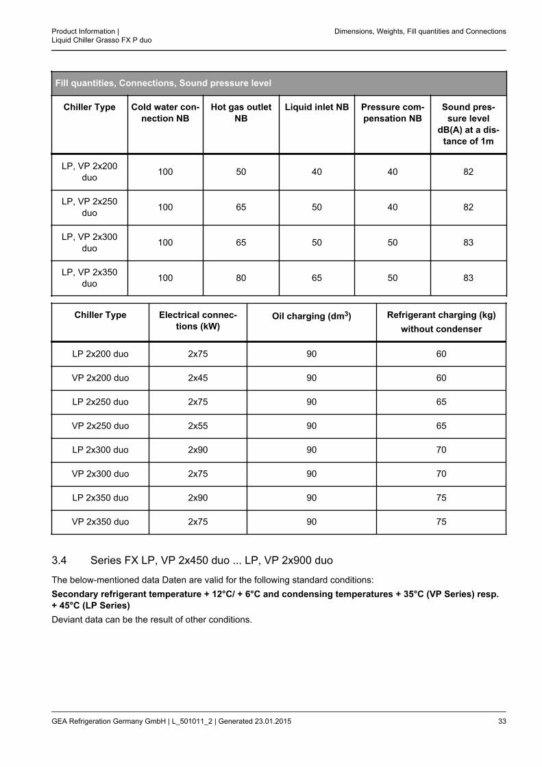
Fill quantities, Connections, Sound pressure level
Chiller Type Cold water con-nection NB
Hot gas outletNB
Liquid inlet NB Pressure com-pensation NB
Sound pres-sure level
dB(A) at a dis-tance of 1m
LP, VP 2x200duo 100 50 40 40 82
LP, VP 2x250duo 100 65 50 40 82
LP, VP 2x300duo 100 65 50 50 83
LP, VP 2x350duo 100 80 65 50 83
Chiller Type Electrical connec-tions (kW)
Oil charging (dm3) Refrigerant charging (kg)without condenser
LP 2x200 duo 2x75 90 60
VP 2x200 duo 2x45 90 60
LP 2x250 duo 2x75 90 65
VP 2x250 duo 2x55 90 65
LP 2x300 duo 2x90 90 70
VP 2x300 duo 2x75 90 70
LP 2x350 duo 2x90 90 75
VP 2x350 duo 2x75 90 75
3.4 Series FX LP, VP 2x450 duo ... LP, VP 2x900 duo
The below-mentioned data Daten are valid for the following standard conditions:Secondary refrigerant temperature + 12°C/ + 6°C and condensing temperatures + 35°C (VP Series) resp.+ 45°C (LP Series)Deviant data can be the result of other conditions.
Product Information |Liquid Chiller Grasso FX P duo
Dimensions, Weights, Fill quantities and Connections
GEA Refrigeration Germany GmbH | L_501011_2 | Generated 23.01.2015 33
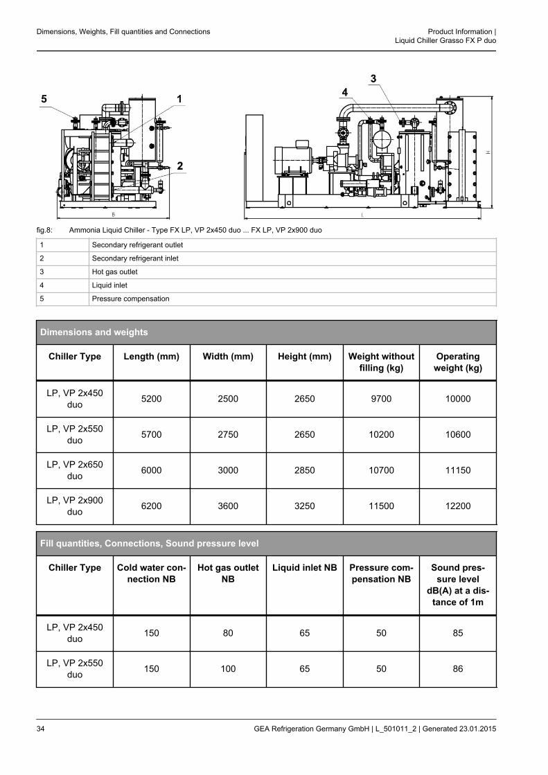
fig.8: Ammonia Liquid Chiller - Type FX LP, VP 2x450 duo ... FX LP, VP 2x900 duo
1 Secondary refrigerant outlet
2 Secondary refrigerant inlet
3 Hot gas outlet
4 Liquid inlet
5 Pressure compensation
Dimensions and weights
Chiller Type Length (mm) Width (mm) Height (mm) Weight withoutfilling (kg)
Operatingweight (kg)
LP, VP 2x450duo 5200 2500 2650 9700 10000
LP, VP 2x550duo 5700 2750 2650 10200 10600
LP, VP 2x650duo 6000 3000 2850 10700 11150
LP, VP 2x900duo 6200 3600 3250 11500 12200
Fill quantities, Connections, Sound pressure level
Chiller Type Cold water con-nection NB
Hot gas outletNB
Liquid inlet NB Pressure com-pensation NB
Sound pres-sure level
dB(A) at a dis-tance of 1m
LP, VP 2x450duo 150 80 65 50 85
LP, VP 2x550duo 150 100 65 50 86
Dimensions, Weights, Fill quantities and Connections Product Information |Liquid Chiller Grasso FX P duo
34 GEA Refrigeration Germany GmbH | L_501011_2 | Generated 23.01.2015
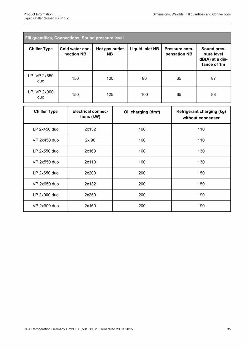
Fill quantities, Connections, Sound pressure level
Chiller Type Cold water con-nection NB
Hot gas outletNB
Liquid inlet NB Pressure com-pensation NB
Sound pres-sure level
dB(A) at a dis-tance of 1m
LP, VP 2x650duo 150 100 80 65 87
LP, VP 2x900duo 150 125 100 65 88
Chiller Type Electrical connec-tions (kW)
Oil charging (dm3) Refrigerant charging (kg)without condenser
LP 2x450 duo 2x132 160 110
VP 2x450 duo 2x 90 160 110
LP 2x550 duo 2x160 160 130
VP 2x550 duo 2x110 160 130
LP 2x650 duo 2x200 200 150
VP 2x650 duo 2x132 200 150
LP 2x900 duo 2x250 200 190
VP 2x900 duo 2x160 200 190
Product Information |Liquid Chiller Grasso FX P duo
Dimensions, Weights, Fill quantities and Connections
GEA Refrigeration Germany GmbH | L_501011_2 | Generated 23.01.2015 35
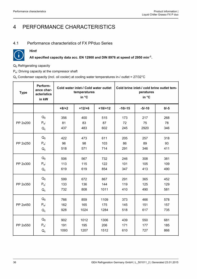
4 PERFORMANCE CHARACTERISTICS
4.1 Performance characteristics of FX PPduo Series
Hint!
All specified capacity data acc. EN 12900 and DIN 8976 at speed of 2950 min-1.
Q0 Refrigerating capacity
Pe: Driving capacity at the compressor shaft
Qc Condenser capacity (incl. oil cooler) at cooling water temperatures in-/ outlet = 27/32°C
Type
Perform-ance char-acteristics
in kW
Cold water inlet-/ Cold water outlettemperatures
in °C
Cold brine inlet-/ cold brine outlet tem-peratures
in °C
+8/+2 +12/+6 +18/+12 -10/-15 -5/-10 0/-5
PP 2x200
Q0
Pe:
Qc
35681437
40083483
51587602
17372245
21775
2920
26878346
PP 2x250
Q0
Pe:
Qc
42296
518
47398
571
611103714
20586291
25789346
31893411
PP 2x300
Q0
Pe:
Qc
506113619
567115619
732122854
246101347
308105413
381109490
PP 2x350
Q0
Pe:
Qc
599133732
672136808
8671441011
291119410
365125490
452129581
PP 2x450
Q0
Pe:
Qc
766162928
8591651024
11091751284
373145518
466151617
578157735
PP 2x550
Q0
Pe:
Qc
9021911093
10121951207
13062061512
439171610
550177727
681185866
Performance characteristics Product Information |Liquid Chiller Grasso FX P duo
36 GEA Refrigeration Germany GmbH | L_501011_2 | Generated 23.01.2015
Type
Perform-ance char-acteristics
in kW
Cold water inlet-/ Cold water outlettemperatures
in °C
Cold brine inlet-/ cold brine outlet tem-peratures
in °C
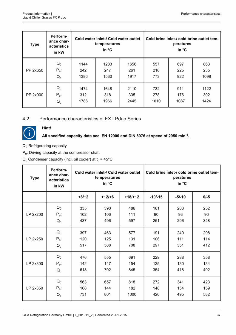
PP 2x650
Q0
Pe:
Qc
11442421386
12832471530
16562611917
557216773
697225922
863235
1098
PP 2x900
Q0
Pe:
Qc
14743121786
16483181966
21103352445
7322781010
9111761087
11223021424
4.2 Performance characteristics of FX LPduo Series
Hint!
All specified capacity data acc. EN 12900 and DIN 8976 at speed of 2950 min-1.
Q0 Refrigerating capacity
Pe: Driving capacity at the compressor shaft
Qc Condenser capacity (incl. oil cooler) at tc = 45°C
Type
Perform-ance char-acteristics
in kW
Cold water inlet-/ Cold water outlettemperatures
in °C
Cold brine inlet-/ cold brine outlet tem-peratures
in °C
+8/+2 +12/+6 +18/+12 -10/-15 -5/-10 0/-5
LP 2x200
Q0
Pe:
Qc
335102437
390106496
486111597
16190251
20393296
25296348
LP 2x250
Q0
Pe:
Qc
397120517
463125588
577131708
191106297
240111351
298114412
LP 2x300
Q0
Pe:
Qc
476142618
555147702
691154845
229125354
288130418
358134492
LP 2x350
Q0
Pe:
Qc
563168731
657144801
8181821000
272148420
341154495
423159582
Product Information |Liquid Chiller Grasso FX P duo
Performance characteristics
GEA Refrigeration Germany GmbH | L_501011_2 | Generated 23.01.2015 37

Type
Perform-ance char-acteristics
in kW
Cold water inlet-/ Cold water outlettemperatures
in °C
Cold brine inlet-/ cold brine outlet tem-peratures
in °C
LP 2x450
Q0
Pe:
Qc
720204924
8402111051
10472211268
347180527
436187623
542193735
LP 2x550
Q0
Pe:
Qc
8492401089
9902491239
12332611494
409212621
514220734
638228866
LP 2x650
Q0
Pe:
Qc
10763041380
12553161571
15643311895
519269788
652280932
8092891098
LP 2x900
Q0
Pe:
Qc
14053921797
16314072038
20184252443
6923431035
8643591223
10663711437
4.3 Performance characteristics of FX VPduo Series
Hint!
All specified capacity data acc. EN 12900 and DIN 8976 at speed of 2950 min-1.
Q0 Refrigerating capacity
Pe: Driving capacity at the compressor shaft
Qc Condenser capacity (incl. oil cooler) at tc = 32°C
Type
Perform-ance char-acteristics
in kW
Cold water inlet-/ Cold water outlettemperatures
in °C
Cold brine inlet-/ cold brine outlet tem-peratures
in °C
+8/+2 +12/+6 +18/+12 -10/-15 -5/-10 0/-5
VP 2x200
Q0
Pe:
Qc
36275437
42277499
52482606
17668244
22171292
27372345
VP 2x250
Q0
Pe:
Qc
42989
518
50091
591
62197718
20980289
26284346
32486410
Performance characteristics Product Information |Liquid Chiller Grasso FX P duo
38 GEA Refrigeration Germany GmbH | L_501011_2 | Generated 23.01.2015

Type
Perform-ance char-acteristics
in kW
Cold water inlet-/ Cold water outlettemperatures
in °C
Cold brine inlet-/ cold brine outlet tem-peratures
in °C
VP 2x300
Q0
Pe:
Qc
514105619
599108707
744114858
25194345
31498412
388101489
VP 2x350
Q0
Pe:
Qc
609124733
709127836
8811351016
380136516
475142617
588145733
VP 2x450
Q0
Pe:
Qc
779151930
9071551062
11271641291
447160607
560167727
693171864
VP 2x550
Q0
Pe:
Qc
9181771095
10691821251
13281931521
447160607
560167727
693171864
VP 2x650
Q0
Pe:
Qc
11642251389
13562311587
16842441928
567203770
710212922
8792171096
VP 2x900
Q0
Pe:
Qc
14952891784
17322972029
21373122449
7432611004
9252721197
11382801418
Product Information |Liquid Chiller Grasso FX P duo
Performance characteristics
GEA Refrigeration Germany GmbH | L_501011_2 | Generated 23.01.2015 39
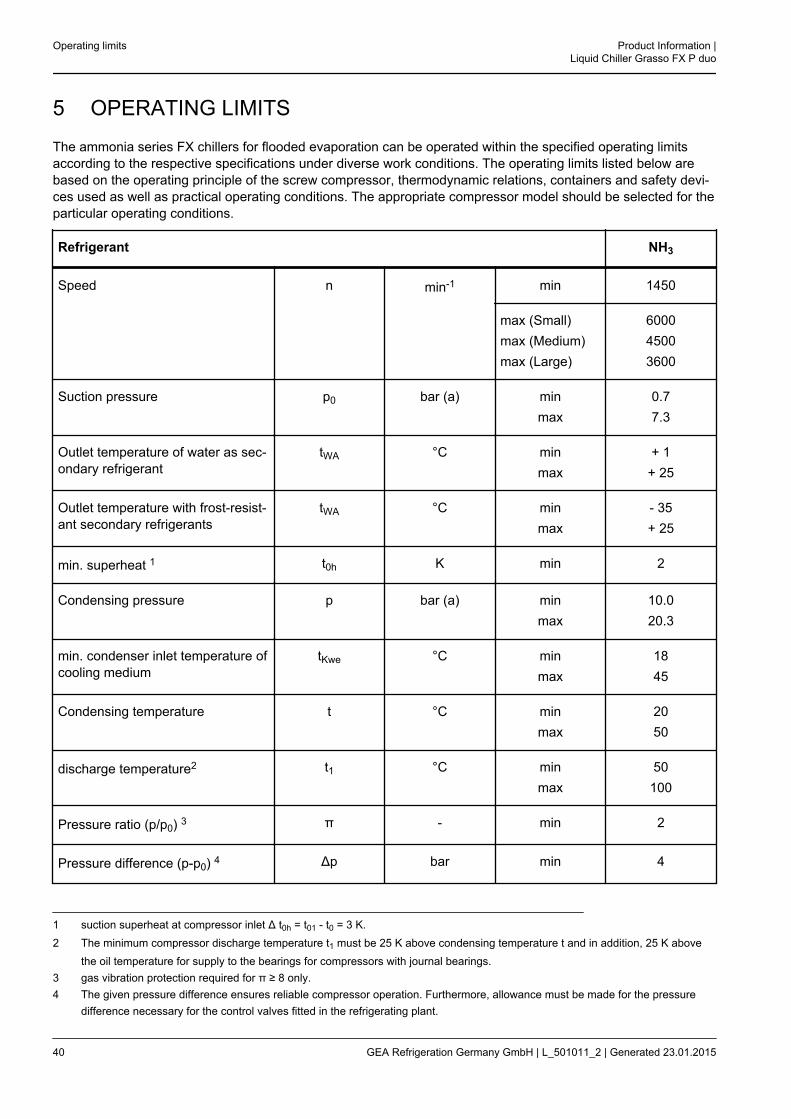
5 OPERATING LIMITS
The ammonia series FX chillers for flooded evaporation can be operated within the specified operating limitsaccording to the respective specifications under diverse work conditions. The operating limits listed below arebased on the operating principle of the screw compressor, thermodynamic relations, containers and safety devi-ces used as well as practical operating conditions. The appropriate compressor model should be selected for theparticular operating conditions.
Refrigerant NH3
Speed n min-1 min 1450
max (Small)max (Medium)max (Large)
600045003600
Suction pressure p0 bar (a) minmax
0.77.3
Outlet temperature of water as sec-ondary refrigerant
tWA °C minmax
+ 1+ 25
Outlet temperature with frost-resist-ant secondary refrigerants
tWA °C minmax
- 35+ 25
min. superheat 1 t0h K min 2
Condensing pressure p bar (a) minmax
10.020.3
min. condenser inlet temperature ofcooling medium
tKwe °C minmax
1845
Condensing temperature t °C minmax
2050
discharge temperature2 t1 °C minmax
50100
Pressure ratio (p/p0) 3 π - min 2
Pressure difference (p-p0) 4 Δp bar min 4
1 suction superheat at compressor inlet Δ t0h = t01 - t0 = 3 K.2 The minimum compressor discharge temperature t1 must be 25 K above condensing temperature t and in addition, 25 K above
the oil temperature for supply to the bearings for compressors with journal bearings.3 gas vibration protection required for π ≥ 8 only.4 The given pressure difference ensures reliable compressor operation. Furthermore, allowance must be made for the pressure
difference necessary for the control valves fitted in the refrigerating plant.
Operating limits Product Information |Liquid Chiller Grasso FX P duo
40 GEA Refrigeration Germany GmbH | L_501011_2 | Generated 23.01.2015

Notes
1. During tests of a certain application case, all the conditions specified in the table must be considered andadhered to.
2. If the specified limits are exceeded for a specific application, the manufacturer must be consulted.
3. In addition to the operation limits stated in the tables, the applicable operating conditions of the compressortype in question must also be considered (e. g. start-up regime, oil pressure, oil quantity, oil type etc.).
4. The oil temperature at the compressor inlet must be least 18°C.
5. Ensure that the oil viscosity will be ≥ 7 cSt at n = 3000 rpm and ≥ 10 cSt at n = 1500 rpm for the oil supply tobearings. Take into account the drop in viscosity due to refrigerant dissolved in the oil!
6. The specified data refer to the operating conditions of a cooling or air-conditioning system.During downtime or start-up, the limiting values may be exceeded or fallen short of for a short (never long-term) period of time.
Product Information |Liquid Chiller Grasso FX P duo
Operating limits
GEA Refrigeration Germany GmbH | L_501011_2 | Generated 23.01.2015 41
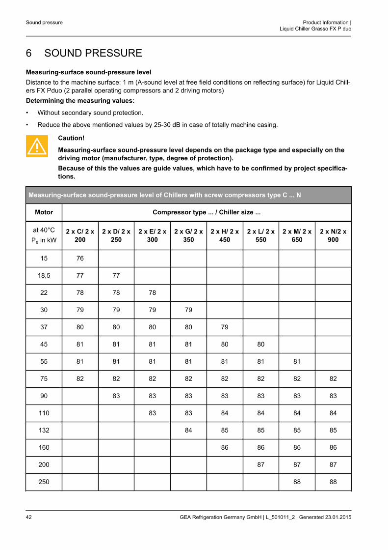
6 SOUND PRESSURE
Measuring-surface sound-pressure levelDistance to the machine surface: 1 m (A-sound level at free field conditions on reflecting surface) for Liquid Chill-ers FX Pduo (2 parallel operating compressors and 2 driving motors)Determining the measuring values:
• Without secondary sound protection.
• Reduce the above mentioned values by 25-30 dB in case of totally machine casing.
Caution!
Measuring-surface sound-pressure level depends on the package type and especially on thedriving motor (manufacturer, type, degree of protection).Because of this the values are guide values, which have to be confirmed by project specifica-tions.
Measuring-surface sound-pressure level of Chillers with screw compressors type C ... N
Motor Compressor type ... / Chiller size ...
at 40°CPe in kW
2 x C/ 2 x200
2 x D/ 2 x250
2 x E/ 2 x300
2 x G/ 2 x350
2 x H/ 2 x450
2 x L/ 2 x550
2 x M/ 2 x650
2 x N/2 x900
15 76
18,5 77 77
22 78 78 78
30 79 79 79 79
37 80 80 80 80 79
45 81 81 81 81 80 80
55 81 81 81 81 81 81 81
75 82 82 82 82 82 82 82 82
90 83 83 83 83 83 83 83
110 83 83 84 84 84 84
132 84 85 85 85 85
160 86 86 86 86
200 87 87 87
250 88 88
Sound pressure Product Information |Liquid Chiller Grasso FX P duo
42 GEA Refrigeration Germany GmbH | L_501011_2 | Generated 23.01.2015

Product Information |Liquid Chiller Grasso FX P duo
Sound pressure
GEA Refrigeration Germany GmbH | L_501011_2 | Generated 23.01.2015 43