liquid scintillation counter and contamination monitoring training presented by: ali shoushtarian...
TRANSCRIPT
Liquid Scintillation Counter
And Contamination Monitoring Training
Presented by: Ali Shoushtarian
Office of Risk Management
October 2009

Topics
• What is Liquid Scintillation?
• Quenching
• Calibration of Liquid Scintillation Counter
• Operating Procedure for Liquid Scintillation Counter
• Contamination Monitoring

Assistant Director, Radiation and Biosafety • Lois Sowden-Plunkett• ext. 3058
Radiation Compliance Specialist• Ali Shoushtarian• ext. 3057
Radiation Safety Program Web Page http://www.uottawa.ca/services/ehss/ionizing.htm
What is Scintillation Counter?
• A scintillation counter measures ionizing radiation
• The sensor, called a scintillator, consists of a transparent crystal, usually phosphor that fluoresces when struck by ionizing radiation.
• A sensitive photomultiplier tube (PMT) measures the light from the crystal. The PMT is attached to an electronic amplifier and other electronic equipment to count the signals produced by the photomultiplier.

Scintillation counter apparatus
• When a charged particle strikes the scintillator, a flash of light is produced.
• Each charged particle produces a flash.
• When a charged particle passes through the phosphor, some of
the phosphor's atoms get excited and emit photons.
• The intensity of the light flash depends on the energy of the charged particles.
• Cesium iodide (CsI) in crystalline form is used as the scintillator for the detection of protons and alpha particles; sodium iodide (NaI) containing a small amount of thallium is used as a scintillator for the detection of gamma waves.
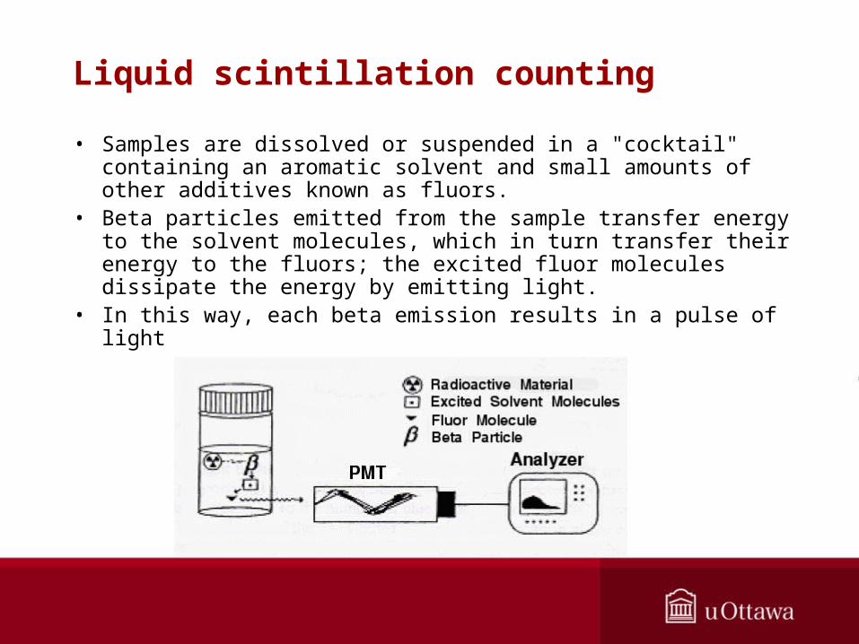
Liquid scintillation counting
• Samples are dissolved or suspended in a "cocktail" containing an aromatic solvent and small amounts of other additives known as fluors.
• Beta particles emitted from the sample transfer energy to the solvent molecules, which in turn transfer their energy to the fluors; the excited fluor molecules dissipate the energy by emitting light.
• In this way, each beta emission results in a pulse of light

Liquid scintillation counting
• Counting efficiencies under ideal conditions range from about 30% for H-3 (a low-energy beta emitter) to nearly 100% for P-32, a high-energy beta emitter.

Liquid scintillation counting
The counter has two photomultiplier tubes connected in a coincidence circuit. The coincidence circuit assures that genuine light pulses, which reach both photomultiplier tubes, are counted, while other pulses (due to noise, for example), which would only affect one of the
tubes, are ignored.

Summary of Scintillation Counter
• Scintillation Cocktail contains solvent and fluor (or solute) molecules.
• Solvent is good at capturing energy of -particle (electron), but often does not produce light.
• A fluor molecule enters an excited state following interaction with excited solvent.
• The excited fluor molecule decays to ground state by emitting light (usually in blue wavelength)
• Blue light is detected by photomultiplier tube (usually two PMT are used to minimize PMT errors.
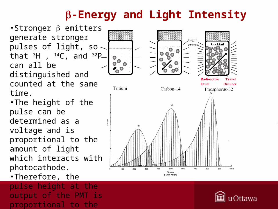
-Energy and Light Intensity•Stronger emitters generate stronger pulses of light, so that 3H , 14C, and 32P can all be distinguished and counted at the same time.•The height of the pulse can be determined as a voltage and is proportional to the amount of light which interacts with photocathode. •Therefore, the pulse height at the output of the PMT is proportional to the energy of the particle.
Quenching
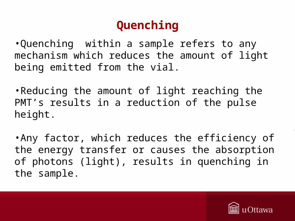
•Quenching within a sample refers to any mechanism which reduces the amount of light being emitted from the vial.
•Reducing the amount of light reaching the PMT’s results in a reduction of the pulse height.
•Any factor, which reduces the efficiency of the energy transfer or causes the absorption of photons (light), results in quenching in the sample.

Quenching1. Chemical Quenching• Chemical quench occurs during the transfer of energy from the solvent to the scintillator. • Chemical agents (e.g. water and other solvents) added to the cocktail with the radioactive sample
interfere with the transfer of kinetic energy between the solvent and the fluor(s).• The results are:
Reduction and loss of lightReduced counting efficiency
2. Colour Quenching• Colour quenching is an attenuation of the photon of light.• The photons produced are absorbed or scattered by the colour in the solution, resulting in reduced
light output available for measurement by the PMT’s.
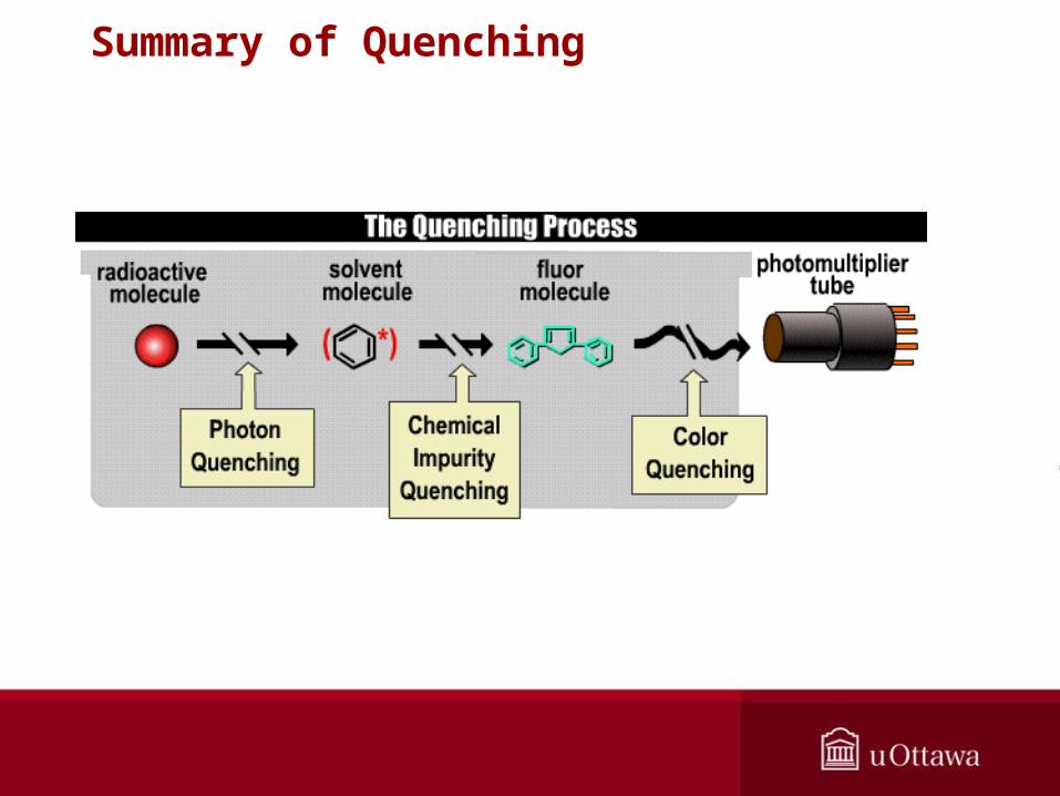
Summary of Quenching

Effects of Quenching1) A shift in the pulse height spectrum of the particles to lower
energy 2) A reduction in the measured CPM of the sample (loss of
counting efficiency). This effect occurs especially with low energy particles.

The Absolute Activity Calculation
•All samples prepared in the laboratory are quenched to some degree
•In order to express the data in units that allow accurate comparison. It is necessary to convert the measured CPM to Disintegrations Per Minute (DPM).
Counting Efficiency = CPM/DPM
DPM= CPM/ Counting Efficiency

Calibration of LSC
• LSC efficiency depends on the degree of quenching, the nature of the sample, the scintillator used and the preparation method.
• Although there are several methods by which LSCs can be calibrated, the external standard method is the most widely used method of efficiency calibration.

Set of 3H Quenched Standards
•A 10 vial standard set each containing the same amount of radioactivity (i.e., dpm) but mixed with increasing amounts of a quenching agent is used.
•Quenching agents absorb the radiation energy
•Thus, the more quenched the sample, the fewer the counts detected in the desired channel.
Set of 3H Quenched Standards
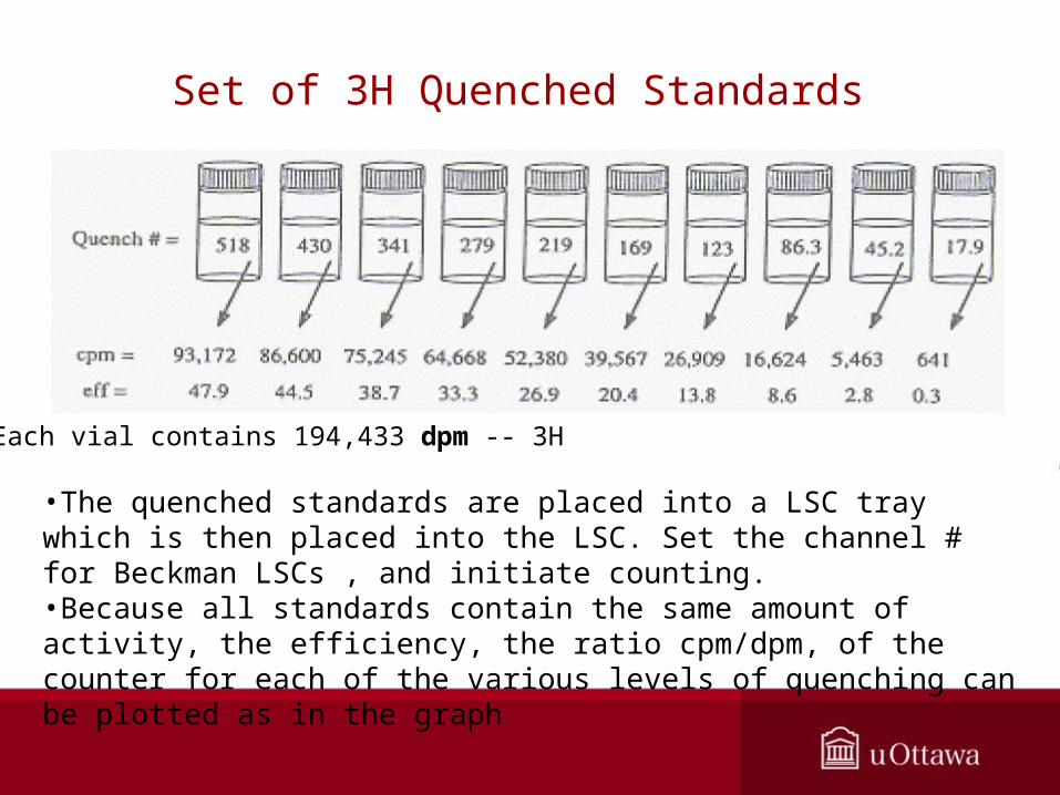
Each vial contains 194,433 dpm -- 3H
•The quenched standards are placed into a LSC tray which is then placed into the LSC. Set the channel # for Beckman LSCs , and initiate counting. •Because all standards contain the same amount of activity, the efficiency, the ratio cpm/dpm, of the counter for each of the various levels of quenching can be plotted as in the graph

Beckman LSC Considerations
• All LSCs operate in the same manner, but different manufacturers may use different terminology or offer more options than others.
• If you are using a Beckman counting system, usually the channel option is the default option for the window setting. Beckman counting systems have 1000 channels and the energy is related to the equation:
Channel # = 72 + 280 log10 (Emax)• where Emax is in keV. Thus the channel settings on a Beckman
LSC to detect the maximum possible beta energy for 3H, 14C/35S and 32P would be approximately 400, 670 and 1000 respectively.

Operating Procedures for LS Counters 1. Read the instruments operating manual to gain familiarity with
the controls and operating characteristics of the machine. 2. Place samples into LSC vials and add the correct amount of
liquid scintillation cocktail (e.g., 5 or 20 ml, as appropriate). Include a background vial which contains scintillation cocktail and a non-radioactive sample
3. Place your sample vials with background vial into the LSC tray and place into the LSC.
4. Set count time, noting that shorter count times give poor counting statistics.
5. Set the appropriate channel and begin your counting.

LSC Overall Summary
• Run your Standards everyday to make sure your LSC is calibrated
• Create a log sheet
• Remember, Energy of your isotopes (keV) is important in order to pick the correct channel

Contamination Monitoring
1) Basic Operation Principles
Function Check• Battery check• Visual check (physical condition, wires, etc)• Foils/Windows• Audio response• Calibration date• Background check• Low response Vs Fast response

Contamination Monitoring
2) Parameters of interest for contamination monitors-Efficiency
Surface
Detector Volume
Detector Covering
Efficiency:1) Distance: 1/r22) Beta Absorption3) Size of window
Not all decay emissionsAre detected!

Contamination Criteria <
Class A: 3.0 Bq/cm2
Class B: 30 Bq/cm2
Class C: 300 Bq/cm2
Decommissioning Criteria <
Class A: 0.3 Bq/cm2
Class B: 3.0 Bq/cm2
Class C: 30 Bq/cm2
Contamination Monitoring

Contamination Monitoring
3) Calculating Efficiency
Eff (%) = ((CPS Source – CPS Background )/ Source Activity (Bq)) X 100
Example: Source activity : 1kBq
Background: 50 cpm
Counts: 15000 cpm
Note: 1 cps= 60 cpm
Eff % = (250 – 0.8)/ 1000 X100
= 24.9%
Contamination Monitoring
4) Calculating Minimum Detection Activity (MDA)• Calculating the smallest amount of contamination a monitor can
detect with 95% confidence• MDA = (4.66√B+3)/Kt [MDA = (4.66√B+3)/Eff X time] • K= factor including efficiency, conversion into Bq, and chemical
or physical yield for sampling techniques.• t= sample count time and background count time• B= Background

Contamination Monitoring
• Example: • Surface area is 15 cm2
• Eff is 2.6%• Time 7 sec (slow response)• Background = 50 cpm = 0.83 cps
MDA = (4.66√B+3)/Eff X time
= (4.66√0.83X7)+3 /0.026 X7X15
= 5.1 Bq/cm2 based on a 7 seconds response time

Contamination Monitoring
5) Converting cpm results into Bq/cm2 for GM pancake
Bq/cm2 = (Cpm – Bkg) / Ec X Ew X 60 X A• where Cpm = counts per minute for the wipe,• Bkg = counts per minute of the background filter,• Ec = scintillation counter efficiency (see note below), or GM efficiency• Ew = wipe efficiency, assume 10% (0.1), and• A = area wiped in cm2.
• Note: As a rule of thumb, when the counter efficiency (Ec) is unknown, the following
• efficiencies can be used for the purpose of counting wipes:• 100% (1) for 32P, 14C, 35S• 75% (0.75) for 125I• 50% (0.5) for 3H and unknowns

Thank you