liquid tolerant capacitive touch keypad reference design
TRANSCRIPT

AC Adapter
5 V
CAPTIVATE_PGMR
ezFET-HID-Bridge
Universal AC Input
3.3 V
TIDM-1021
MSP430FR2633
CapTIvateTMMCU
SBW
UART
GPIOs
CapTIvateTM
I/O
12 LEDs
Buzzer
Capacitive Sensor Panel
1 2 3
4 5 6
7 8 9
A 0 B
1TIDUE90–July 2018Submit Documentation Feedback
Copyright © 2018, Texas Instruments Incorporated
Liquid Tolerant Capacitive Touch Keypad Design
TI Designs: TIDM-1021Liquid Tolerant Capacitive Touch Keypad Design
DescriptionThe Liquid Tolerant Capacitive Touch Keypad Design(TIDM-1021) is a reference design that implements aliquid-tolerant capacitive-touch human-machineinterface (HMI). The design integrates the TIMSP430FR2633 microcontroller (MCU) and featureshigh-performance CapTIvate™ touch technology withan optimized sensor layout design and software. Thisreference design demonstrates how to designcapacitive touch hardware and software that can workreliably when exposed to liquids and that can passchallenging tests for conductive noise immunity.
Resources
TIDM-1021 Design FolderMSP430FR2633 Product Folder
ASK Our E2E™ Experts
Features• MSP430™ CapTIvate MCU for Liquid-Tolerant
Capacitive-Touch Sensing• Advanced Human-Machine Interface Design With
12-Button Keypad• 12 LEDs Driven by the MSP430 CapTIvate MCU
for Backlighting• Passes IEC 61000-4-6 Conducted Noise Immunity
Test at 3-Vrms Stress Level• No False Touch Detection and Accurately Detects
Touched Button Under IPX5 Rating Test With ACPower
Applications• Appliances• Factory Automation & Control• Building Automation
An IMPORTANT NOTICE at the end of this TI reference design addresses authorized use, intellectual property matters and otherimportant disclaimers and information.

System Description www.ti.com
2 TIDUE90–July 2018Submit Documentation Feedback
Copyright © 2018, Texas Instruments Incorporated
Liquid Tolerant Capacitive Touch Keypad Design
1 System DescriptionCapacitive touch technology is becoming more popular in today's homes and workspace. However, onechallenge is that the sensing measurement results change if liquid is on the touch surface. This isparticularly important for appliance, factory automation, and building automation applications. The TIDM-1021 reference design demonstrates a capacitive touch solution that can reliably operate in anenvironment with liquid on the touch sensors. This reference design includes an optimized sensor layoutand software algorithms to help prevent false triggers and also to ensure accurate touch detection evenwhen liquid is present. The system operates reliably with a well grounded power supply in the IPX5 ratingtest environment.
1.1 Key System Specifications
(1) This reference design is optimized for noise immunity and liquid tolerance but is not optimized for low power consumption. Formore information on low-power optimization, refer to the CapTIvate Technology Guide.
Table 1. Key System Specifications
PARAMETER SPECIFICATIONSButtons 12 square buttons, 10 mm x 10 mm eachMeasurement mode Mutual capacitance modeScan rate 25 HzInput voltage 3.3 VDCAverage current consumption (1) 3.63 mW (1.1 mA)Serial interface 250-kbps UARTMSP430FR2633 FRAM code footprint 8314 bytes (54%)Printed circuit board (PCB) size (W x L) 63 mm x 109 mmPCB thickness 1.6-mm 2-layer PCBNoise immunity test IEC 61000-4-6 conducted noise immunity (CNI) with 3-Vrms noise voltage
Although the hardware and firmware design can be different depending on specific design requirements,this reference design is optimized to use mutual capacitance topology for 12 buttons with a well groundedpower supply. The design works reliably when exposed to a continuous stream of water and operatesunder these conditions without false detections and with accurate detection of a touched button.

Capacitive Sensor Panel
1 2 3
4 5 6
7 8 9
A 0 B
Capacitive Sensor Panel
1 2 3
4 5 6
7 8 9
A 0 B
Capacitive Sensor Panel
1 2 3
4 5 6
7 8 9
A 0 B
Dry Water Droplet Continuous Stream
PCB
Sensor
Electrodes Overlay Water Droplet Continuous Stream
Capacitive Sensor Panel
1 2 3
4 5 6
7 8 9
A 0 B
8
4
2
BA
6
0
5
Ca el
AC Adapter
5 V
CAPTIVATE_PGMR
ezFET-HID-Bridge
Universal AC Input
3.3 V
TIDM-1021
MSP430FR2633
CapTIvateTMMCU
SBW
UART
GPIOs
CapTIvateTM
I/O
12 LEDs
Buzzer
Capacitive Sensor Panel
1 2 3
4 5 6
7 8 9
A 0 B
www.ti.com System Overview
3TIDUE90–July 2018Submit Documentation Feedback
Copyright © 2018, Texas Instruments Incorporated
Liquid Tolerant Capacitive Touch Keypad Design
2 System Overview
2.1 Block DiagramFigure 1 shows the block diagram of this reference design, which includes:
● 12 mutual capacitance buttons
● 12 LEDs for touch indication feedback
● An audio buzzer for touch indication feedback
● An MSP430FR2633 MCU
Figure 1. TIDM-1021 Block Diagram
2.2 Design Considerations
2.2.1 Classification of Scenarios With Liquid PresentScenarios with liquid present are difficult to quantify, because the fluid has no fixed shape and itsmovement is dynamic. This document describes operation in three scenarios: dry, with water droplets, andwith a continuous stream flow (see Figure 2). The amount of liquid applied on the touch surface is differentin each scenario.
Figure 2. Scenarios With Liquid Present

MSP430TM
CapTIvateTM MCU
Cground
CSelf
Self Sensor
Dry, Touch
CBody
Human Finger
MSP430TM
CapTIvateTM MCU
Cground
CSelf
Self Sensor
Wet, No Touch
CLiquid
Liquid
System Overview www.ti.com
4 TIDUE90–July 2018Submit Documentation Feedback
Copyright © 2018, Texas Instruments Incorporated
Liquid Tolerant Capacitive Touch Keypad Design
2.2.2 Liquid Influence on Capacitive Touch SensingIt is critical to design the user interface to work reliably under all expected environments. Unlike amechanical button that uses physical movement to trigger a touch event, a capacitive touch button isfundamentally different. It triggers a touch event by detecting the changes in the electric field andcapacitance of the sensors over time. Unfortunately, this operating principle makes capacitive touchbuttons more vulnerable to influence by liquids. The changes in the electric field and capacitance of thesensors can be due to human interaction, such as a finger or hand, but the human body is not the onlything that can affect the electric field and capacitance. Water and other liquids on the touch surface canalso create changes to the electric field and capacitance similar to the changes causes by the humanbody. The changes caused by the presence of liquids result in the false touch detections or inaccuratetouch detections.
Different end equipment can have different requirements for handling detection when liquids are present.For some products, the user interface is designed to reject any touch events if there is liquid covering thetouch surface. For other products, the user interface needs to accurately detect a touch event even whenliquid covers the touch surface.
2.2.3 Self Capacitance and Mutual CapacitanceSelf capacitance and mutual capacitance are the two capacitive sensing methods to detect touch events,and they behave slightly different when exposed to liquids.
2.2.3.1 Self CapacitanceThe self capacitance method measures changes in capacitance with respect to earth ground. When auser's finger touches the self capacitance sensor electrode, the finger provides a path that couples thesensor to earth ground (see Figure 3). Because of this, an additional touch capacitance is added to Cself,which increases the capacitance. When a liquid covers the touch surface, the liquid also provides a paththat couples the sensor to the surrounding ground on the sensor PCB. The additional capacitance Cliquid isadded to Cself and increases the capacitance.
With the self capacitance method, both the finger touch and liquid presence increase the sensedcapacitance, which means that the self capacitance method is sensitive to liquid on the touch surface.
Human finger provides a path for coupling thesensor to earth ground, which increases thecapacitance CSelf.
Liquid covers the touch surface also provides apath for coupling the sensor to the surroundingground or other components, which increases thecapacitance CSelf.
Figure 3. Influence of Liquid on Self Capacitance Method

www.ti.com System Overview
5TIDUE90–July 2018Submit Documentation Feedback
Copyright © 2018, Texas Instruments Incorporated
Liquid Tolerant Capacitive Touch Keypad Design
2.2.3.2 Mutual CapacitanceThe mutual capacitance method measures changes in capacitance between two electrodes. When afinger touches the area between the TX electrode and RX electrode, the finger reduces the electric fieldcoupling between them, which reduces the mutual capacitance Cmutual (see Figure 4). This reductionhappens because the finger is coupled to earth ground, so the user interaction disturbs the electric fieldpropagation between the two electrodes.
When liquid covers the touch surface, it affects the sensing capacitance in two ways. The first effect is thatthe liquid couples to the surrounding ground on the sensor PCB, which reduces the electric field couplingbetween the RX and TX and reduces the mutual capacitance, Cmutual. Because liquid has higher dielectricconstant than air, the second effect is that the liquid on the area between the RX and TX electrodesincreases the electric field coupling between the electrodes, which increases the mutual capacitance. Theincrease of Cmutual causes the measurement result to go in the opposite direction of a touch, and thisopposite result is called a "negative touch". This "negative touch" behavior helps to prevent false touchdetection when liquid is present.
For a fixed mutual capacitance sensor design, the overall effect of liquids depends on:1. The amount of grounding path around the sensors. Liquid couples the sensor to larger grounding path
reduces the mutual capacitance and causes the measurement result to go the same direction as atouch.
2. The amount of liquid that is present on the touch surface, which determines how much the mutualcapacitance increases and how much the measurement result goes in the opposite direction of atouch.

MSP430TM
CapTIvateTMMCU
Cground
CMutual
Mutual TX
Mutual RX
Dry, No Touch
MSP430TM
CapTIvateTMMCU
Cground
CMutual
Mutual TX
Mutual RX
Wet, No Touch
CLiquid
Liquid
MSP430TM
CapTIvateTMMCU
Cground
CMutual
Mutual TX
Mutual RX
Dry, No Touch
MSP430TM
CapTIvateTMMCU
Cground
CMutual
Mutual TX
Mutual RX
Dry, Touch
CBody
Human
Finger
System Overview www.ti.com
6 TIDUE90–July 2018Submit Documentation Feedback
Copyright © 2018, Texas Instruments Incorporated
Liquid Tolerant Capacitive Touch Keypad Design
When a finger touches an area where a TX electrode meets RX electrode, it reduces the capacitanceCmutual between TX and RX electrodes. This is because the human fingers are coupled to earth groundso the user’s interaction has the effect of disturbing the electric field propagation between the twoelectrodes.
1. Liquid is also coupled to ground or other components around the sensor. When liquid covers thearea where a TX electrode meets RX electrode, it also reduces the capacitance Cmutual betweenTX and RX electrodes.
2. Liquid has higher dielectric constant than air so by having liquid on top of the area between the RXand TX it increases the electric field coupling between RX and TX which increases thecapacitance Cmutual.
Figure 4. Liquid Influence on Mutual Capacitance Method
2.2.4 Other ConsiderationsIn addition to the design considerations that are discussed in this document, other factors must also betaken into account when designing a liquid-tolerant capacitive touch system.
For example, some applications require the capacitive touch system to work properly with liquid presentwhile the user wears gloves to touch the panel. In these cases, the designer must define the expected useconditions and also to consider the tradeoff between responsiveness to gloved fingers and liquid-tolerantperformance. The material, structure, and thickness of the glove can significantly affect capacitive touchperformance parameters (such as sensitivity). The different capacitive sensing methods (self and mutual)also behave slightly differently when gloves are used while touching the sensors.
Other common design considerations include:• Mechanical stackup, which can affect touch sensitivity and reliability• Environmental temperature drift, which can cause a drift in the sensing measurement result

&DS7,YDWH��7HFKQRORJ\�&RUH
Event Timer
Reference Capacitors
Conversion Control
+Finite State
Machine Logic
Dedicated LDO Regulator
bLpmControl Voltage Reference
Low Frequency Clock
Interrupt RequestCAPT_IV_TIMER
MSP Peripheral Bus
Interrupt RequestCAPT_IV_END_OF_CONVERSIONCAPT_IV_MAX_COUNT_ERRORCAPT_IV_DETECTIONCAPT_IV_CONVERSION_COUNTER
Self Mode
Mutual (Projected) Mode
&DS7,YDWH���6RIWZDUH�/LEUDU\�3DUDPHWHUparam
DVCC
&DS7,YDWH��7HFKQRORJ\
Measurement Block(s)
Block n
Block 2
Block 1
Frequency Hopping &
Spread Spectrum Oscillator
ui8FreqDiv
Cx
Cm
IO Mux
bIdleState
ui8TxPinui8TxBlock
ui8RxPinui8RxBlock
ui8RxPinui8RxBlock
MutualMode
Self Mode
www.ti.com System Overview
7TIDUE90–July 2018Submit Documentation Feedback
Copyright © 2018, Texas Instruments Incorporated
Liquid Tolerant Capacitive Touch Keypad Design
• Subsystem interconnection, which can affect the touch sensitivity and introduce additional noise to themeasurement result
Overall, it is critical for a product designer to consider typical use cases and system factors (such as theones listed above) that can affect the capacitive touch performance. This document does not describe allof these factors. This reference design is configured to reliably detect bare-finger touch when exposed to acontinuous stream of water and a 3-Vrms conductive noise coupling directly to the power supply whileeliminating false touch detections.
2.3 Highlighted Products
2.3.1 MSP430FR2633The MSP430FR2633 is a 16-bit microcontroller with programmable ferroelectric memory (FRAM) andCapTIvate capacitive sensing technology. CapTIvate technology is a flexible and robust capacitive-sensing technology for user interface applications such as buttons, sliders, wheels, and proximity sensors.The CapTIvate technology in the MSP430FR2633 has several key features designed to ensure accuratetouch detection in noisy environments. Figure 5 shows the high-level block diagram of the CapTIvateperipheral architecture.
Figure 5. CapTIvate Peripheral Architecture
MSP430TM
CapTIvateTMMCU
Self
Sensor
CAP1.0
Ground
MSP430TM
CapTIvateTMMCU
Self
Sensor
CAP1.0
Ground
Self
Sensor
System Overview www.ti.com
8 TIDUE90–July 2018Submit Documentation Feedback
Copyright © 2018, Texas Instruments Incorporated
Liquid Tolerant Capacitive Touch Keypad Design
2.4 System Design TheorySection 2.2.1 describes different scenarios with liquids present. The requirements for liquid tolerance onHMI subsystem varies for different products. Some applications require that there are no false touchdetections and that there is accurate touch detection in the liquid droplet scenario. Some applicationsmust ensure the same performance under the continuous liquid streaming scenario. Some applicationsrequire the system to block all of the touch events in the continuous liquid streaming scenario.
The hardware and firmware design of applications will differ depending on the design requirements. Thisreference design uses a mutual capacitance topology for 12 buttons with a well grounded power supply towork reliably in the continuous liquid streaming scenario without any false detections and with accuratedetection of a touched button.
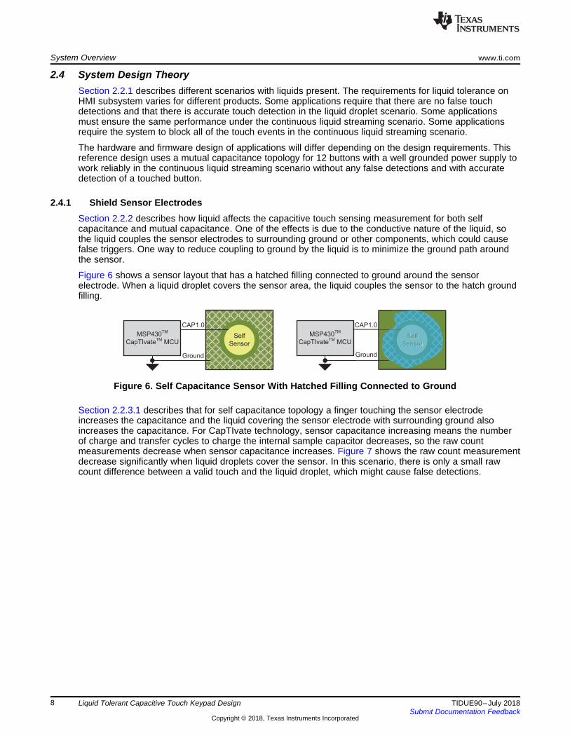
2.4.1 Shield Sensor ElectrodesSection 2.2.2 describes how liquid affects the capacitive touch sensing measurement for both selfcapacitance and mutual capacitance. One of the effects is due to the conductive nature of the liquid, sothe liquid couples the sensor electrodes to surrounding ground or other components, which could causefalse triggers. One way to reduce coupling to ground by the liquid is to minimize the ground path aroundthe sensor.
Figure 6 shows a sensor layout that has a hatched filling connected to ground around the sensorelectrode. When a liquid droplet covers the sensor area, the liquid couples the sensor to the hatch groundfilling.
Figure 6. Self Capacitance Sensor With Hatched Filling Connected to Ground
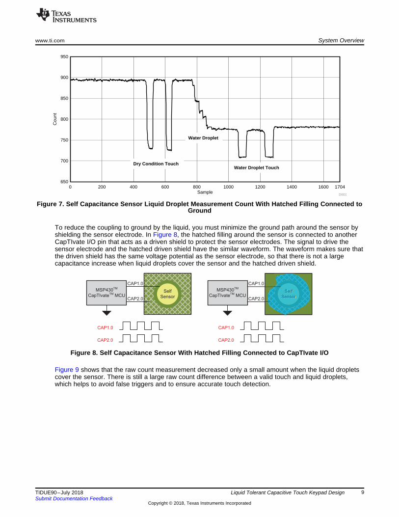
Section 2.2.3.1 describes that for self capacitance topology a finger touching the sensor electrodeincreases the capacitance and the liquid covering the sensor electrode with surrounding ground alsoincreases the capacitance. For CapTIvate technology, sensor capacitance increasing means the numberof charge and transfer cycles to charge the internal sample capacitor decreases, so the raw countmeasurements decrease when sensor capacitance increases. Figure 7 shows the raw count measurementdecrease significantly when liquid droplets cover the sensor. In this scenario, there is only a small rawcount difference between a valid touch and the liquid droplet, which might cause false detections.
MSP430TM
CapTIvateTMMCU
Self
Sensor
CAP1.0
CAP2.0
CAP2.0
CAP1.0
MSP430TM
CapTIvateTMMCU
Self
Sensor
CAP1.0
CAP2.0
CAP2.0
CAP1.0
Self
Sensor
Sample
Cou
nt
0 200 400 600 800 1000 1200 1400 1600 1704650
700
750
800
850
900
950
Water Droplet
Dry Condition TouchWater Droplet Touch
D001
www.ti.com System Overview
9TIDUE90–July 2018Submit Documentation Feedback
Copyright © 2018, Texas Instruments Incorporated
Liquid Tolerant Capacitive Touch Keypad Design
Figure 7. Self Capacitance Sensor Liquid Droplet Measurement Count With Hatched Filling Connected toGround
To reduce the coupling to ground by the liquid, you must minimize the ground path around the sensor byshielding the sensor electrode. In Figure 8, the hatched filling around the sensor is connected to anotherCapTIvate I/O pin that acts as a driven shield to protect the sensor electrodes. The signal to drive thesensor electrode and the hatched driven shield have the similar waveform. The waveform makes sure thatthe driven shield has the same voltage potential as the sensor electrode, so that there is not a largecapacitance increase when liquid droplets cover the sensor and the hatched driven shield.
Figure 8. Self Capacitance Sensor With Hatched Filling Connected to CapTIvate I/O
Figure 9 shows that the raw count measurement decreased only a small amount when the liquid dropletscover the sensor. There is still a large raw count difference between a valid touch and liquid droplets,which helps to avoid false triggers and to ensure accurate touch detection.

1 2 3
4 5 6
7 8 9
A 0 B
TX
RX
Sample
Cou
nt
0 200 400 600 800 1000 1200 1400 1500450
500
550
600
650
700
750
800
850
900
950
Water Droplet
Dry Condition Touch
Water Droplet Touch
D002
System Overview www.ti.com
10 TIDUE90–July 2018Submit Documentation Feedback
Copyright © 2018, Texas Instruments Incorporated
Liquid Tolerant Capacitive Touch Keypad Design
Figure 9. Self Capacitance Sensor Liquid Droplet Raw Count With Hatched Filling Connected toCapTIvate I/O
2.4.2 Mutual Capacitance ShieldingA mutual capacitance sensor requires a RX electrode and a TX electrode. Typically, mutual capacitiveelectrodes can be multiplexed with other mutual capacitive electrodes. This means that more than onebutton can share a common signal. However, to optimize the sensor design for liquid tolerance, the designneeds a driven shield to protect the sensors from coupling to surrounding ground or other components. Toaccurately detect the touched sensor during heavy continuous liquid flow, the design should have anindividual RX signal for each sensor instead of multiplexing the RX signal with other sensors.
Unlike in the self capacitance electrode design, in which the hatched filling connects to a CapTIvate I/O forthe driven shield, in mutual capacitance mode, the hatched filling connects to the TX signal. This hatchedfilling is used as a driven shield to protect all of the sensors and the shared TX electrode for all thesensors. For each individual RX electrodes, use a solid pad instead of hollow traces to protect the sensorsfrom coupling to the ground or other components on other layers of the PCB. All of theserecommendations about the design of mutual capacitance sensors are optimized for a keypad applicationthat can operate reliably when exposed to heavy continuous liquid flow.
Figure 10 shows the layout of the 12-button keypad. For more details on the layout design, refer toSection 4.3 or download the design files from the TIDM-1021 page.
Figure 10. 12-Button Keypad Mutual Capacitance Design Layout
www.ti.com System Overview
11TIDUE90–July 2018Submit Documentation Feedback
Copyright © 2018, Texas Instruments Incorporated
Liquid Tolerant Capacitive Touch Keypad Design
2.4.3 Design for Noise ImmunityThis reference design is optimized for a keypad application that operates reliably in a heavy continuousflow of liquid. This design also considers noise immunity requirements. This design passed the IEC61000-4-6 Conducted Noise test at 3-Vrms stress level with Class A pass or fail criteria. Class A requiresthe following:• The equipment under test must not exhibit any false touch detections during or after the test.• The equipment under test must always detect valid touches during and after the test.
Section 3.2 includes the detailed conductive noise test data. For more information on how to design fornoise immunity, refer to the Noise-Tolerant Capacitive-Touch Human-Machine Interfaces Design Guide.
2.4.4 Power Supply Grounding EffectFor a capacitive touch system, the measurement result is impacted by all the elements in the wholecapacitive loop so how the system is connected to the earth ground can significantly affect themeasurement results.
In typical battery-powered scenarios (see Figure 11), the system is not directly connected to earth ground.It is coupled to earth ground with free space coupling. And the further the system is away from the earthground the weaker the coupling between the system and earth ground which means the smaller Cground-
coupling. From the mutual mode capacitive touch sensing perspective, the weak coupling minimize thecapability of human finger touch to reduce the mutual capacitance Cmutual which result in lower touchsensitivity.
In typical scenarios with a well grounded power supply (see Figure 11), the system is either directlyconnected to earth ground or strongly coupled to earth ground. From the perspective of mutualcapacitance touch sensing, the strong coupling increases the reduction of the mutual capacitance (Cmutual)when a human finger touches the surface, which results in higher touch sensitivity.
The sensitivity difference between a battery-powered system and a wall-powered system is moresignificant in scenarios with liquid present. This is because liquid has higher dielectric constant than air, soliquid on top of the area between the RX and TX increases the electric field coupling between RX and TX,which increase the capacitance, Cmutual. With larger Cmutual, the reduction of sensitivity in a battery-poweredsystem is more significant.
To improve the performance for a battery-operated system with heavy continuously flowing liquid, thesystem must increase the coupling to earth ground. A number of methods can improve the systemcoupling to earth ground. For example, enlarging the physical size of the hardware system, adding a largeground plane to the system, and placing the system close to physical earth ground surface like a wall orthe floor.
The measurement data for both the battery-powered scenario and the wall-powered scenario are includedin Section 3.2. The measurement data in this document for a battery-powered scenario demonstrates thesensitivity reduction but each system is designed differently. First, this reference design is only a referencefor the human-machine interface subsystem and not for the whole system. Second, as previouslydescribed for a battery-powered system, the capacitive touch sensitivity is highly depend on the systemcoupling to earth ground.

Battery Powered System
MSP430TM
CapTIvateTM MCU System
Cground-coupling
CMutual
Mutual TX
Mutual RX
Human Finger
Well Grounded Power Supply System
MSP430TM
CapTIvateTM MCU System
CMutual
Mutual TX
Mutual RX
Human Finger
Cbody Cbody
Well Grounded Power Supply
System Overview www.ti.com
12 TIDUE90–July 2018Submit Documentation Feedback
Copyright © 2018, Texas Instruments Incorporated
Liquid Tolerant Capacitive Touch Keypad Design
Figure 11. Battery-Powered and Well Grounded Power Supply Capacitive Touch Systems

www.ti.com Hardware, Software, Test Requirements, and Test Results
13TIDUE90–July 2018Submit Documentation Feedback
Copyright © 2018, Texas Instruments Incorporated
Liquid Tolerant Capacitive Touch Keypad Design
3 Hardware, Software, Test Requirements, and Test Results
3.1 Required Hardware and Software
3.1.1 HardwareThe hardware used in this reference design include the TIDM-1021 PCB (see Figure 12), an MSP430CapTIvate MCU programmer board (CAPTIVATE-PGMR) (see Figure 13), and a CapTIvatecommunications isolation board (CAPTIVATE-ISO) (see Figure 14).
The programer board is used to program the MSP430FR2633 MCU on the TIDM-1021 PCB and also toprovide the communication to the CapTIvate Design Center GUI for tunning the sensors and collecting themeasurement data. The communication isolation board is used to maintain UART communication whenTIDM-1021 PCB is powered from an external power source. This is mainly for test data collectionpurposes and, if the system is powered from the host PC, there is no need for the CAPTIVATE-ISO board.
The TIDM-1021 PCB includes:• 12 mutual capacitance buttons• 12 LEDs for touch indication feedback• An audio buzzer for touch indication feedback• An MSP430FR2633 MCU• A 20-pin connector to CapTIvate MCU programmer board
Section 3.2 lists other hardware used to test this reference design in different cases.
Figure 12. TIDM-1021 Hardware PCB Front (Left) and Back (Right)

Hardware, Software, Test Requirements, and Test Results www.ti.com
14 TIDUE90–July 2018Submit Documentation Feedback
Copyright © 2018, Texas Instruments Incorporated
Liquid Tolerant Capacitive Touch Keypad Design
Figure 13. MSP430 CapTIvate MCU Programmer Board (CAPTIVATE-PGMR)
Figure 14. CapTIvate Communications Isolation Board (CAPTIVATE-ISO)
3.1.2 SoftwareThe TIDM-1021 firmware uses the CapTIvate software library to process raw capacitive measurementsfrom the CapTIvate peripheral on the MSP430FR2633 MCU. This software is based on code generated bythe CapTIvate Design Center, and the application layer call back function is added to provide the liquidtolerance feature and to control the feedback (the LED and buzzer).
The process of creating this firmware:1. Use CapTIvate Design Center to generate the code based on the sensor configuration.2. Disable the negative touch automatic recalibration feature.
Remove the MAP_CAPT_testForNegativeTouchRecalibration() function in the CAPT_updateUI()function in the CAPT_Manager.c file.
3. Enable the noise immunity feature.Change CAPT_CONDUCTED_NOISE_IMMUNITY_ENABLE to true in the CAPT_UserConfig.h file.
4. Implement the call back function. Figure 15 shows the callback function flow chart.

Sensor LTA halt = falseNo Negative
TouchStart Callback
Function
Sensor LTA halt = true
Yes
Sensor Previous Touch
Yes
No
Sensor Touch Detect
NoTouched Button = noneLED_Index = none
Turn off the audio buzzer
Yes
Touched_Button = dominantButtonLED_Index = Touched_Button
Turn on the audio buzzer
Update LED
End Callback Function
www.ti.com Hardware, Software, Test Requirements, and Test Results
15TIDUE90–July 2018Submit Documentation Feedback
Copyright © 2018, Texas Instruments Incorporated
Liquid Tolerant Capacitive Touch Keypad Design
The callback function will first check if there is a "negative touch" to determine whether to halt the LTA.This is to prevent the LTA to track with the "negative touch" count which could trigger false touch detectionafter the liquid is removed. And then the callback will determine whether to update touched button basedon the previous touch status. The callback uses the dominate button algorithm to determine the actualtouched button after the sensor touch is detected.
For more information about the firmware and the CapTIvate Design Center project, download them fromthe TIDM-1021 page, and visit CapTIvate Design Center GUI page CapTIvate Design Center GUI.
Figure 15. Callback Function Flow Chart

Testing
PCB
Testing
PCB
PCB Holder
3-mm thick plastic overlayWaterTank
WaterPump
PlasticTube
PCBHolder
TubeHolder
SupportFrame
Hardware, Software, Test Requirements, and Test Results www.ti.com
16 TIDUE90–July 2018Submit Documentation Feedback
Copyright © 2018, Texas Instruments Incorporated
Liquid Tolerant Capacitive Touch Keypad Design
3.2 Test and Results
3.2.1 Liquid Test With Well Grounded Power Supply
3.2.1.1 Continuous Water Flow TestTest SetupFigure 16 shows a tank filled with water and a 12-V pump to provide the continuous water flow for thistest. The TIDM-1021 PCB is attached on the back of a 3-mm-thick plastic overlay with 467MP double-sided adhesive. The overlay is mounted on a PCB holder to hold the test unit on a support frame. Thissetup allows a continuous water flow directly on the touch sensor area. Figure 17 shows a photograph ofthe test setup. The water used in all the liquid test cases is tap water from the local piped supply.
Figure 16. Liquid Test Setup
Figure 17. Continuous Water Flow Test Setup

External DCPower Supply
LaptopCapTIvateTM Design Center GUI
CAPTIVATE-PGMR
CAPTIVATE-ISO
TIDM-1021 PCB
www.ti.com Hardware, Software, Test Requirements, and Test Results
17TIDUE90–July 2018Submit Documentation Feedback
Copyright © 2018, Texas Instruments Incorporated
Liquid Tolerant Capacitive Touch Keypad Design
The TIDM-1021 PCB is connected to the CapTIvate communications isolation board (CAPTIVATE-ISO)and the MSP430 CapTIvate MCU programmer board (CAPTIVATE-PGMR) (see Figure 18). This setupcollects the data with a laptop through the USB cable and provides the 3.3-V power to the system usingan external DC power supply.
Figure 18. Test Hardware Setup
Test Procedures1. A user touches each button from Button 1 to Button B.2. Turn on the water pump with continuous water flow.3. A user touches each button from Button 1 to Button B.4. Turn off the water pump.
Test ResultFigure 19 shows the sensor measurement count result for this test. The Y axis represents the sensormeasurement count, and the X axis represents the number of samples. Each color represents the data fora specific button. The data shows that the sensor is calibrated at a baseline count of 350, and the touchincreases the count to approximately 550 in dry conditions. When the flowing water is applied on the touchsensor area, the data shows the "negative touch" behavior (see Section 2.2.3.2). The flowing watercauses the measurement result to go in the opposite direction of a touch event, so no false touch isdetected. While the water is continuously flowing on the touch sensor area, each touch event can stillcause a distinguishable count increase for the touched button. Based on this test result and by using thesoftware algorithm in Section 3.1.2, the system can reliably operate when exposed to continuous waterflow, with no false touch detections and with accurate detection of a button touch.

Samples
Cou
nt
0 500 1000 1500 2000 2500 3000 3500200
250
300
350
400
450
500
550
600
650
700
Flow WaterBegin
Flow WaterEnd
Dry Condition
D003
Button 1Button 2
Button 3Button 4
Button 5Button 6
Button 7Button 8
Button 9Button A
Button 0Button B
Hardware, Software, Test Requirements, and Test Results www.ti.com
18 TIDUE90–July 2018Submit Documentation Feedback
Copyright © 2018, Texas Instruments Incorporated
Liquid Tolerant Capacitive Touch Keypad Design
Figure 19. Sensor Count Result With Continuous Water Flow (Well Grounded Power Supply)
3.2.1.2 Continuous Water Spray TestTest SetupThe test setup is similar to the continuous water flow test in Section 3.2.1.1. The difference is a spraynozzle added on the plastic water tube to provide a continuous water spray on the touch sensor area (seeFigure 20).
Figure 20. Continuous Water Spray Test Setup
Test ProceduresThe test procedures are the same as the continuous water flow testing (see Section 3.2.1.1).
Test Result

Samples
Sen
sor
Cou
nt
0 500 1000 1500 2000 2500 3000 3300200
250
300
350
400
450
500
550
600
650
700
750
Spray WaterBegin
Spray WaterEnd
Dry Condition
D004
Button 1Button 2
Button 3Button 4
Button 5Button 6
Button 7Button 8
Button 9Button A
Button 0Button B
www.ti.com Hardware, Software, Test Requirements, and Test Results
19TIDUE90–July 2018Submit Documentation Feedback
Copyright © 2018, Texas Instruments Incorporated
Liquid Tolerant Capacitive Touch Keypad Design
Figure 21 shows the sensor measurement count result. The result is similar to the continuous water flowtest result (see Section 3.2.1.1). The difference is that when the continuous water spray is applied on thetouch sensor area, the measurement count is not as consistent as the continuous water flow test case.This is because the spray water does not contact the touch sensor area consistently. The "negative touch"behavior is still present, which means that the spray water causes the measurement result to go in theopposite direction of a touch event. Therefore, there is no false touch detection. While the continuouswater spray is applied on the touch sensor area, each touch event still causes a distinguishable countincrease for the touched button. Based on this test result and by using the dominant button lock algorithm(see Section 3.1.2), the system can reliably operate when exposed to continuous water spray, with nofalse touch detections and with accurate detection of a button touch.
Figure 21. Sensor Count Result With Continuous Water Spray (Well Grounded Power Supply)
3.2.2 Conductive Noise Immunity TestTest SetupThe test setup follows the IEC 61000-4-6 standard and complies with the guidelines provided in thestandard. Three separate tests must be performed for conducted immunity:
• Class B verification with the standard frequency sweep as specified to ensure that no false detectsoccur for any sensor due to the noise
• Class A verification for a single button must remain in detect for the test to ensure that valid touchescan be detected in the presence of noise throughout the frequency range.
• Class A verification of the functionality of the entire panel while at specific frequencies that are mostsusceptible to conducted noise.
This reference design is tested under the IEC 61000-4-6 test level 2 with 3-Vrms test voltage. The noise iscoupled directly onto the 3.3-V system power supply.
Test ProceduresTwo types of test data are shown: frequency sweeps and frequency dwells. Frequency sweeps are testsin which the response of an electrode is measured while the noise frequency is swept. The response istested with and without a simulated touch present. Frequency dwells are tests in which the response of anelectrode is measured while the noise frequency is held constant. The response to several sequentialtouches is tested to compare the touched and untouched states.
Test ResultThere are four data sets for this test: a sweep with no touch, a sweep with a touch, and two dwell tests,one for dry condition and another for flowing water condition.

Sample
Cou
nt
0 2000 4000 6000 8000 10000 12000 14000 16000 17871150
200
250
300
350
400
450
500
550
600
650
700
D006
4.000 MHz3.675 MHz3.275 MHz2.800 MHz
Sample
Cou
nt
0 2000 4000 6000 8000 10000 12000 14000 16000 17871300
350
400
450
D005
Filtered Count LTA Threshold
Hardware, Software, Test Requirements, and Test Results www.ti.com
20 TIDUE90–July 2018Submit Documentation Feedback
Copyright © 2018, Texas Instruments Incorporated
Liquid Tolerant Capacitive Touch Keypad Design
Figure 22 shows the result of the frequency sweep with no touch. The filtered count remains below thetouch threshold throughout the test with no false button detection. The raw data (4 MHz, 3.675 MHz, 3.275MHz, 2.800 MHz) identifies the fundamental conversion frequencies and the harmonics. When the noisefrequency overlaps with a conversion frequency or one of its harmonics, the measurements at thatconversion frequency exhibit corrupted and unusable data. The other frequencies remain undisturbed. Thesweep with no touch passes the test with no false detections.
Figure 22. Sensor Data for 3 Vrms Conductive Noise Test; No Touch Sweep; Dry Condition
Sample
Cou
nt
0 2000 4000 6000 8000 10000 12000 14000 16000 180000
50
100
150
200
250
300
350
400
450
500
550
600
650
700
750
800
D008
4.000 MHz3.675 MHz3.275 MHz2.800 MHz
Sample
Cou
nt
0 2000 4000 6000 8000 10000 12000 14000 16000 18000300
350
400
450
500
550
600
650
700
750
800
D007
Filtered CountLTAThreshold
www.ti.com Hardware, Software, Test Requirements, and Test Results
21TIDUE90–July 2018Submit Documentation Feedback
Copyright © 2018, Texas Instruments Incorporated
Liquid Tolerant Capacitive Touch Keypad Design
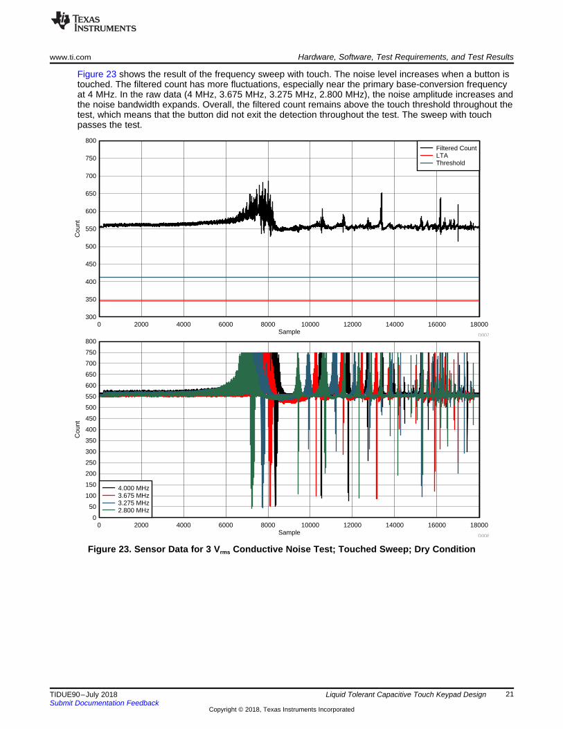
Figure 23 shows the result of the frequency sweep with touch. The noise level increases when a button istouched. The filtered count has more fluctuations, especially near the primary base-conversion frequencyat 4 MHz. In the raw data (4 MHz, 3.675 MHz, 3.275 MHz, 2.800 MHz), the noise amplitude increases andthe noise bandwidth expands. Overall, the filtered count remains above the touch threshold throughout thetest, which means that the button did not exit the detection throughout the test. The sweep with touchpasses the test.
Figure 23. Sensor Data for 3 Vrms Conductive Noise Test; Touched Sweep; Dry Condition

Sample
Cou
nt
0 100 200 300 400 500 6000
50
100
150
200
250
300
350
400
450
500
550
600
650
700
750
800
850
D010
4.000 MHz3.675 MHz3.275 MHz2.800 MHz
Sample
Cou
nt
0 100 200 300 400 500 600300
350
400
450
500
550
600
650
700
750
800
850
D009
Filtered CountLTAThreshold
Hardware, Software, Test Requirements, and Test Results www.ti.com
22 TIDUE90–July 2018Submit Documentation Feedback
Copyright © 2018, Texas Instruments Incorporated
Liquid Tolerant Capacitive Touch Keypad Design
The 4-MHz dwell point was chosen because it directly overlaps with the primary base-conversionfrequency of 4 MHz. Figure 24 shows two sequential touches under dry condition. The dominant noise ispresent only in the raw data at 4 MHz. The filtered count remains below the threshold when there is notouch and remains above the threshold with no fluctuations when there is a touch. This is a passing dwelltest.
Figure 24. Sensor Data for 3 Vrms Conductive Noise Test; Dwell at 4 MHz, Dry Condition
Sample
Cou
nt
0 100 200 300 400 4970
50
100
150
200
250
300
350
400
450
500
550
600
650
700
750
800
850
D012
4.000 MHz3.675 MHz3.275 MHz2.800 MHz
Sample
Cou
nt
0 100 200 300 400 499300
350
400
450
500
550
600
650
700
750
800
850
D011
Filtered CountLTAThreshold
www.ti.com Hardware, Software, Test Requirements, and Test Results
23TIDUE90–July 2018Submit Documentation Feedback
Copyright © 2018, Texas Instruments Incorporated
Liquid Tolerant Capacitive Touch Keypad Design
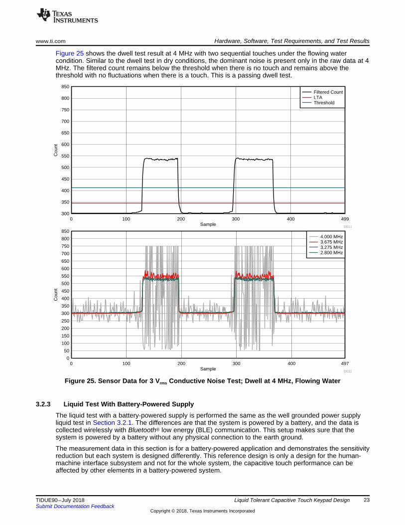
Figure 25 shows the dwell test result at 4 MHz with two sequential touches under the flowing watercondition. Similar to the dwell test in dry conditions, the dominant noise is present only in the raw data at 4MHz. The filtered count remains below the threshold when there is no touch and remains above thethreshold with no fluctuations when there is a touch. This is a passing dwell test.
Figure 25. Sensor Data for 3 Vrms Conductive Noise Test; Dwell at 4 MHz, Flowing Water
3.2.3 Liquid Test With Battery-Powered SupplyThe liquid test with a battery-powered supply is performed the same as the well grounded power supplyliquid test in Section 3.2.1. The differences are that the system is powered by a battery, and the data iscollected wirelessly with Bluetooth® low energy (BLE) communication. This setup makes sure that thesystem is powered by a battery without any physical connection to the earth ground.
The measurement data in this section is for a battery-powered application and demonstrates the sensitivityreduction but each system is designed differently. This reference design is only a design for the human-machine interface subsystem and not for the whole system, the capacitive touch performance can beaffected by other elements in a battery-powered system.

Samples
Sen
sor
Cou
nt
0 500 1000 1500 2000 2500 3000 3300200
250
300
350
400
450
500
550
600
Flow WaterBegin
Flow WaterEnd
Dry Condition
D013
Button 1Button 2
Button 3Button 4
Button 5Button 6
Button 7Button 8
Button 9Button A
Button 0Button B
Hardware, Software, Test Requirements, and Test Results www.ti.com
24 TIDUE90–July 2018Submit Documentation Feedback
Copyright © 2018, Texas Instruments Incorporated
Liquid Tolerant Capacitive Touch Keypad Design
3.2.3.1 Continuous Water Flow TestFigure 26 shows the sensor measurement count results for this test. The Y axis represents the sensormeasurement count and the X axis represents number of samples. Each color represents the data for aspecific button. The data shows that the sensors are calibrated at baseline count of 350, and the touchincreases the count to approximately 450 in dry conditions. The increased delta is smaller than the wellgrounded power supply scenario.
When the flowing water is applied on the touch sensor area, the data shows the "negative touch" behavior(see Section 2.2.3.2). The flowing water causes the measurement result to go in the opposite direction ofa touch event, so no false touch is detected. While the water is continuously flowing on the touch sensorarea, each touch event still causes a count increase, and the touched button is still distinguishable.However, the amplitude of the count increase is significantly lower compare to well grounded powersupply scenario. As the data shows, it is challenge to set the touch threshold for the system to workreliably under both dry conditions and flowing water conditions. If the threshold tracks with the "negativetouch" behavior, there could be a false detection after the flowing water is removed, because the datashows that the count returns to the baseline when the flowing water stops.
This data is only intended to demonstrate the sensitivity reduction, and Section 2.4.4 describes methodsto design a system with stronger coupling to earth ground, which improves the sensitivity in flowing waterconditions.
Section 2.4.4 explains the sensitivity reduction in battery powered system for both dry conditions andflowing water conditions. More water on the touch sensor area causes more significant sensitivityreduction. Section 3.2.3.2 describes the spray water test, which has less water applied to the touchsurface, compared to the flowing water test.
Figure 26. Sensor Count Result With Continuous Water Flow (Battery Power)
3.2.3.2 Continuous Water Spray TestFigure 27 shows that the sensors are calibrated at a baseline count of 350, and a touch increases thecount to approximately 450 in dry conditions. The increased delta is smaller compare than in the wellgrounded power supply scenario. When the spray water is applied on the touch sensor area, the datashows the "negative touch" behavior (see Section 2.2.3.2). The water spray causes the measurementresult to go in the opposite direction of a touch event, so no false touch is detected. While the water iscontinuously spraying on the touch sensor area, each touch event still causes a count increase, and thetouched button is still distinguishable. The sensitivity under the water spray condition is comparable withthe sensitivity under the dry condition, which means that the touch threshold can be set to reliably work forboth dry and spray water conditions.

Samples
Sen
sor
Cou
nt
0 500 1000 1500 2000 2500 3000200
250
300
350
400
450
500
550
600
Spray WaterBegin Spray Water
End
Dry Condition
D014
Button 1Button 2
Button 3Button 4
Button 5Button 6
Button 7Button 8
Button 9Button A
Button 0Button B
www.ti.com Hardware, Software, Test Requirements, and Test Results
25TIDUE90–July 2018Submit Documentation Feedback
Copyright © 2018, Texas Instruments Incorporated
Liquid Tolerant Capacitive Touch Keypad Design
Figure 27. Sensor Count Result With Continuous Water Spray (Battery Power)
3.2.4 Third Party Test ReportIntertek Testing Services in Plano, TX tested this TI Design PCB in accordance with the standard"Degrees of Protection Provided By Enclosures (IP Code) IEC 60529". The objective of the test was todemonstrate that the unit was able to work properly under IPX5 conditions, the pass criteria consisted of:• No false triggers during the test or after test• Accurately detect the button being touched during the test
The test unit includes a TIDM-1021 PCB mounted in a sealed enclosures and powered by a well groundedAC power supply.
A detailed test report is available from http://www.ti.com/lit/pdf/tidl001.
LED holes
Individual RX electrode
Shared TX electrode
Design Files www.ti.com
26 TIDUE90–July 2018Submit Documentation Feedback
Copyright © 2018, Texas Instruments Incorporated
Liquid Tolerant Capacitive Touch Keypad Design
4 Design Files
4.1 SchematicsTo download the schematics, see the design files on the TIDM-1021 page.
4.2 Bill of MaterialsTo download the bill of materials (BOM), see the design files on the TIDM-1021 page.
4.3 PCB Layout Recommendations
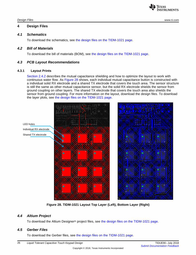
4.3.1 Layout PrintsSection 2.4.2 describes the mutual capacitance shielding and how to optimize the layout to work withcontinuous water flow. As Figure 28 shows, each individual mutual capacitance button is constructed witha individual solid RX electrode and a shared TX electrode that covers the touch area. The sensor structureis still the same as other mutual capacitance sensor, but the solid RX electrode shields the sensor fromground coupling on other layers. The shared TX electrode that covers the touch area also shields thesensor from ground coupling. For more information on the layout, download the design files. To downloadthe layer plots, see the design files on the TIDM-1021 page.
Figure 28. TIDM-1021 Layout Top Layer (Left), Bottom Layer (Right)
4.4 Altium ProjectTo download the Altium Designer® project files, see the design files on the TIDM-1021 page.
4.5 Gerber FilesTo download the Gerber files, see the design files on the TIDM-1021 page.

www.ti.com Design Files
27TIDUE90–July 2018Submit Documentation Feedback
Copyright © 2018, Texas Instruments Incorporated
Liquid Tolerant Capacitive Touch Keypad Design
4.6 Assembly DrawingsTo download the assembly drawings, see the design files on the TIDM-1021 page.
5 Software FilesTo download the software files, see the design files on the TIDM-1021 page.
6 Related Documentation1. CapTIvate™ Technology Guide2. Enabling Noise Tolerant Capacitive Touch HMIs With MSP CapTIvate™ Technology
6.1 TrademarksCapTIvate, E2E, MSP430 are trademarks of Texas Instruments.Altium Designer is a registered trademark of Altium LLC or its affiliated companies.Bluetooth is a registered trademark of Bluetooth SIG.All other trademarks are the property of their respective owners.
7 About the AuthorYiding Luo is a Systems Application Engineer at Texas Instruments. He focuses on capacitive-touchsensing solution design includes hardware development, software development, and ecosystemdevelopment. He has been working at TI since 2015. Yiding received his Bachelor of Science in ElectricalEngineering (BSEE) from the University of Texas at Dallas in 2015.

IMPORTANT NOTICE FOR TI DESIGN INFORMATION AND RESOURCES
Texas Instruments Incorporated (‘TI”) technical, application or other design advice, services or information, including, but not limited to,reference designs and materials relating to evaluation modules, (collectively, “TI Resources”) are intended to assist designers who aredeveloping applications that incorporate TI products; by downloading, accessing or using any particular TI Resource in any way, you(individually or, if you are acting on behalf of a company, your company) agree to use it solely for this purpose and subject to the terms ofthis Notice.TI’s provision of TI Resources does not expand or otherwise alter TI’s applicable published warranties or warranty disclaimers for TIproducts, and no additional obligations or liabilities arise from TI providing such TI Resources. TI reserves the right to make corrections,enhancements, improvements and other changes to its TI Resources.You understand and agree that you remain responsible for using your independent analysis, evaluation and judgment in designing yourapplications and that you have full and exclusive responsibility to assure the safety of your applications and compliance of your applications(and of all TI products used in or for your applications) with all applicable regulations, laws and other applicable requirements. Yourepresent that, with respect to your applications, you have all the necessary expertise to create and implement safeguards that (1)anticipate dangerous consequences of failures, (2) monitor failures and their consequences, and (3) lessen the likelihood of failures thatmight cause harm and take appropriate actions. You agree that prior to using or distributing any applications that include TI products, youwill thoroughly test such applications and the functionality of such TI products as used in such applications. TI has not conducted anytesting other than that specifically described in the published documentation for a particular TI Resource.You are authorized to use, copy and modify any individual TI Resource only in connection with the development of applications that includethe TI product(s) identified in such TI Resource. NO OTHER LICENSE, EXPRESS OR IMPLIED, BY ESTOPPEL OR OTHERWISE TOANY OTHER TI INTELLECTUAL PROPERTY RIGHT, AND NO LICENSE TO ANY TECHNOLOGY OR INTELLECTUAL PROPERTYRIGHT OF TI OR ANY THIRD PARTY IS GRANTED HEREIN, including but not limited to any patent right, copyright, mask work right, orother intellectual property right relating to any combination, machine, or process in which TI products or services are used. Informationregarding or referencing third-party products or services does not constitute a license to use such products or services, or a warranty orendorsement thereof. Use of TI Resources may require a license from a third party under the patents or other intellectual property of thethird party, or a license from TI under the patents or other intellectual property of TI.TI RESOURCES ARE PROVIDED “AS IS” AND WITH ALL FAULTS. TI DISCLAIMS ALL OTHER WARRANTIES ORREPRESENTATIONS, EXPRESS OR IMPLIED, REGARDING TI RESOURCES OR USE THEREOF, INCLUDING BUT NOT LIMITED TOACCURACY OR COMPLETENESS, TITLE, ANY EPIDEMIC FAILURE WARRANTY AND ANY IMPLIED WARRANTIES OFMERCHANTABILITY, FITNESS FOR A PARTICULAR PURPOSE, AND NON-INFRINGEMENT OF ANY THIRD PARTY INTELLECTUALPROPERTY RIGHTS.TI SHALL NOT BE LIABLE FOR AND SHALL NOT DEFEND OR INDEMNIFY YOU AGAINST ANY CLAIM, INCLUDING BUT NOTLIMITED TO ANY INFRINGEMENT CLAIM THAT RELATES TO OR IS BASED ON ANY COMBINATION OF PRODUCTS EVEN IFDESCRIBED IN TI RESOURCES OR OTHERWISE. IN NO EVENT SHALL TI BE LIABLE FOR ANY ACTUAL, DIRECT, SPECIAL,COLLATERAL, INDIRECT, PUNITIVE, INCIDENTAL, CONSEQUENTIAL OR EXEMPLARY DAMAGES IN CONNECTION WITH ORARISING OUT OF TI RESOURCES OR USE THEREOF, AND REGARDLESS OF WHETHER TI HAS BEEN ADVISED OF THEPOSSIBILITY OF SUCH DAMAGES.You agree to fully indemnify TI and its representatives against any damages, costs, losses, and/or liabilities arising out of your non-compliance with the terms and provisions of this Notice.This Notice applies to TI Resources. Additional terms apply to the use and purchase of certain types of materials, TI products and services.These include; without limitation, TI’s standard terms for semiconductor products http://www.ti.com/sc/docs/stdterms.htm), evaluationmodules, and samples (http://www.ti.com/sc/docs/sampterms.htm).
Mailing Address: Texas Instruments, Post Office Box 655303, Dallas, Texas 75265Copyright © 2018, Texas Instruments Incorporated