lisega catalogue
DESCRIPTION
Lisega spring hangers, spring supports, shock absorbers, struts, pipe clamps etc.TRANSCRIPT

Edition October 2001
The LISEGA product program embraces all elements
that are required to create the latest, state of the art
pipe support concepts.
These components correspond to the LISEGA standardization
philosophy and are organized in a modular system
with load and attachment compatibility.
Containing the complete product program, this catalog is in full
compliance with LICAD (Rev. 8), the LISEGA pipe support design program.
The catalog is available, identical in all details, as a pdf-file:
either as a CD-Rom or directly from our homepage.
LISEGA reserves the right to introduce revisions in
the interests of further technical development.

Zeven, GermanyHeadquarters
Bondoufle, France
Newport, TN, USA
Wittenburg, Germany(LISEGA facility for fasteners)

STANDARD SUPPORTS 2010
LISEGA is differentAs far as the mutual success of customers and suppliers is concerned, one can’tdo without the other! Accordingly we act as partners for our clients and under-take every effort to make them aware of that. We know this can only be reachedby optimum performance. Not only that - we have to be the best. This way, wecan convince customers or perhaps even rouse their enthusiasm - and we areonly satisfied when that’s achieved!
The constant challenge excites us, for we love suc-cess. There is no greater motivation than success.In order to be the best, we have specialized. Our whole concentration is centered on pipe supports, and has been for more than 35 years.
Regarding our particular sphere, we have a com-prehensive understanding of it. Not only qualityand price determine the customer benefits of theproduct; low application costs are equally import-ant. Often, these alone can prove decisive for thesuccess or failure of a project.
Customer benefit demands the highest efficiencyfrom us. This is why performance with system hasbecome the foundation of the organization and anessential factor in our strategy. On this keynotewe also support product application: standardi-zation, the modular system, series production and user software (LICAD) are themost important elements to this end. Just for this, our customers have made usinternational leaders!
With the catalog in hand, Standard Supports 2010, we wish to present our latesttechnology, and via comprehensive and clearly structured information, make a further contribution to efficient product application.
This is quite in the spirit of our objectives - superior product quality at the keen-est costs for the customer! Even if these aims do seemingly compete, we stickto them, because this is the most effective way to recommend ourselves as partners - and above all, we have already proved it.
That’s why LISEGA is different… through performance with system!
Hans-Herlof Hardtke Rolf Münnich
(from left to right)
Harald Lange, director international sales
Hans-Herlof Hardtke, president, CEO
Wolfgang Tetzlaff, head of German sales
Rolf Münnich, exec. VP, marketing & sales

0
1
2
3
4
5
6
7
8
9
0
1
2
3
4
5
6
7
8
9
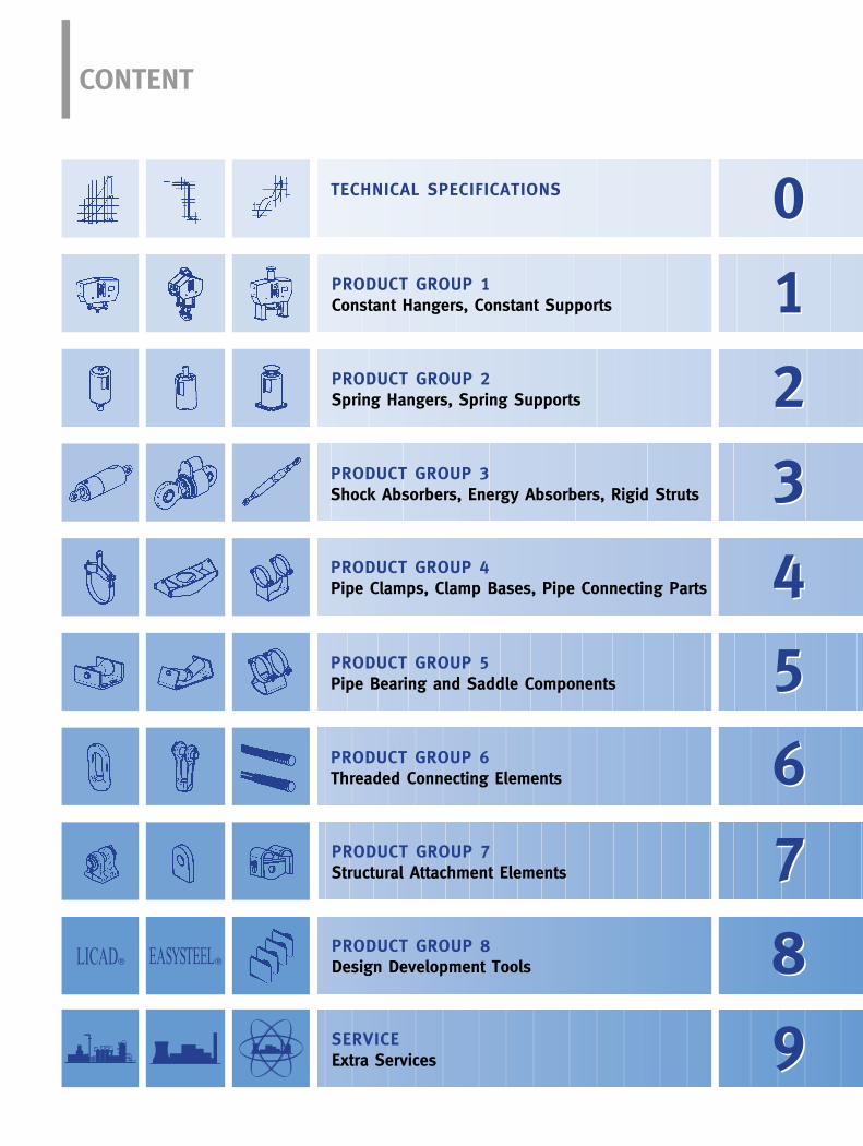
CONTENT
TECHNICAL SPECIFICATIONS
PRODUCT GROUP 1Constant Hangers, Constant Supports
PRODUCT GROUP 2Spring Hangers, Spring Supports
PRODUCT GROUP 3Shock Absorbers, Energy Absorbers, Rigid Struts
PRODUCT GROUP 4Pipe Clamps, Clamp Bases, Pipe Connecting Parts
PRODUCT GROUP 5Pipe Bearing and Saddle Components
PRODUCT GROUP 6Threaded Connecting Elements
PRODUCT GROUP 7Structural Attachment Elements
PRODUCT GROUP 8Design Development Tools
SERVICEExtra Services
LICAD® EASYSTEEL®

LLIISSEEGGAA AAGGGGeerrmmaannyyIInndduussttrriieeggeebbiieett HHoocchhkkaammpp2277440044 ZZeevveennPPoossttffaacchh 113355772277339933 ZZeevveennTTeell..:: ((00 4422 8811)) 771133--00FFaaxx:: ((00 4422 8811)) 771133--221144EE--MMaaiill:: iinnffoo@@lliisseeggaa..ddeeIInntteerrnneett:: wwwwww..lliisseeggaa..ddee
LLIISSEEGGAA SS..àà..rr..ll..FFrraanncceeZZ..II.. LLaa MMaarriinniièèrree2211,, rruuee GGuutteennbbeerrgg9911991199 BBoonnddoouuffllee CCeeddeexxTTeell..:: ((00))11 6600 8866 4400 2211FFaaxx:: ((00))11 6600 8866 4488 2288EE--MMaaiill:: iinnffoo@@lliisseeggaa..ffrrIInntteerrnneett:: wwwwww..lliisseeggaa..ffrr
LLIISSEEGGAA IInncc..UUSSAA337755,, LLiisseeggaa BBoouulleevvaarrddNNeewwppoorrtt,, TTeennnneesssseeee 3377882211TTeell..:: ((00)) 442233 662255--22000000FFaaxx:: ((00)) 442233 662255--99000099EE--MMaaiill:: iinnffoo@@lliisseeggaa..ccoommIInntteerrnneett:: wwwwww..lliisseeggaa..ccoomm
LLIISSEEGGAA LLttdd..GGrreeaatt BBrriittaaiinn MMiiddssuummmmeerr HHoouussee441155 aa,, MMiiddssuummmmeerr BBoouulleevvaarrddBBuucckkiinngghhaammsshhiirree,, MMKK99 33BBNNCCeennttrraall MMiillttoonn KKeeyynneessTTeell..:: ((00 1199 0088)) 223311 228822FFaaxx:: ((00 1199 0088)) 223311 332255EE--MMaaiill:: ssaalleess@@lliisseeggaa..ccoo..uukkIInntteerrnneett:: wwwwww..lliisseeggaa..ccoo..uukk
LLIISSEEGGAACChhiinnaaBBeeiijjiinngg OOffffiicceeRRmm.. 551100,, HHuuaa YYiinngg PPllaazzaa 1144 AA,, FFuu XXiinngg RRooaadd PPoosstt CCooddee 110000003366TTeell..:: ((001100)) 6633 995511 220055FFaaxx:: ((001100)) 6633 995555 446666EE--MMaaiill:: lliisseeggaaccoo@@ppuubblliicc..bbttaa..nneett..ccnn
US
US
Umschlag US.qx 29.07.2002 10:47 Uhr Seite 2
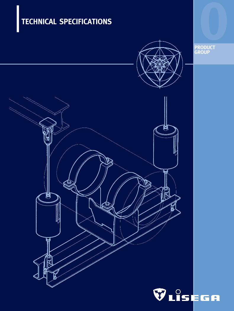
0TECHNICAL SPECIFICATIONS
PRODUCTGROUP


0.0
TECHNICAL SPECIFICATIONS
1. Standard supports ________________________________________________ 0.11.1 Requirements ____________________________________________________ 0.11.2 Definition________________________________________________________ 0.12. LISEGA standard supports _________________________________________ 0.12.1 Scope___________________________________________________________ 0.12.2 Design features __________________________________________________ 0.12.3 Principle of the optimum design type________________________________ 0.23. LISEGA modular system ___________________________________________ 0.23.1 Fundamentals ____________________________________________________ 0.23.2 Scope___________________________________________________________ 0.23.3 Product groups___________________________________________________ 0.23.4 Load groups _____________________________________________________ 0.23.5 Permissible loads_________________________________________________ 0.33.6 Travel ranges ____________________________________________________ 0.63.7 Type designations ________________________________________________ 0.63.8 Type designation system __________________________________________ 0.74. Standards and calculations_________________________________________ 0.95. Materials ________________________________________________________ 0.96. Qualification levels for standard and nuclear application________________ 0.97. Welding________________________________________________________ 0.108. Surface treatment _______________________________________________ 0.108.1 Standard coating systems_________________________________________ 0.108.2 Standard surface protection acc. to products ________________________ 0.118.3 Extended surface protection_______________________________________ 0.118.4 Extended surface protection acc. to products ________________________ 0.128.5 Surface protection in extremely aggressive atmospheres _________________ 0.129. Connection dimensions___________________________________________ 0.129.1 Installation dimension E __________________________________________ 0.129.2 Regulation of the total installation length ___________________________ 0.1310. Operational behavior_____________________________________________ 0.1310.1 Function _______________________________________________________ 0.1310.2 Spring relaxation ________________________________________________ 0.1411. Quality assurance________________________________________________ 0.1411.1 Fundamentals___________________________________________________ 0.1411.2 Quality management _____________________________________________ 0.1411.3 International qualifications ________________________________________ 0.1411.4 Tests and qualifications __________________________________________ 0.1511.5 Suitability tests acc. to KTA 3205.3 and VGB R 510 L_________________ 0.1512. Shipment_______________________________________________________ 0.1613. Warranty _______________________________________________________ 0.1614. Technical modifications___________________________________________ 0.16
CONTENTS PAGE
1
2
3
4
5
6
7
8
9
1
2
3
4
5
6
7
8
9
TECHNICALSPECIFICATIONS
00

0.1
1. STANDARD SUPPORTS
1.1 RequirementsFor the support of industrial piping systems,the use of standard supports is regarded aswell proven, up-to-date technology.
Only a correspondingly high level of standar-dization in support components can adequatelysatisfy the justifiable demand for productsthat are technically top-class and economi-cally attractive at the same time. The complexrequirements for modern pipe supports are:
➜ reliable functioning➜ maintenance-free operation➜ low unit prices➜ simple planning with DP systems➜ instant availability➜ economical installation strategy➜ easy to install designs➜ supplementary service benefits
1.2 DefinitionStandard supports must fulfill the followingcriteria:
➜ component shapes are uniform and designed for optimum exploitation of material
➜ units are compatible regarding connectingdimensions and loading capacity
➜ units are cataloged and clearly identifiableby a designation system
➜ components are manufactured in series production
➜ components comply with the relevant standards and international regulations
➜ functional capacity, suitability and durability of the units is well proven
➜ components are certified and approved for use
The relevant codes for pipe supports inGerman plant construction (power plants),VGB guideline R 510 L, require the preferen-tial use of standard supports and define thecriteria as follows:
“Standard supports are pipe support com-ponents, the construction of which, in formand dimensions as well as in the designdata relating to loading capacity, is certificatedand cataloged, and which are manufacturedaccording to firmly established, reproducibleprocedures, e.g. series production”.
2. LISEGA STANDARD SUPPORTS
2.1 ScopeAt LISEGA, standard supports form the basisof a comprehensive performance package. A complete program from more than 8000standardized components thereby covers alloperational loads, temperatures and travelranges normally met in piping systems inindustrial plant construction:
➜ � 1200°F operating temperature for pipe clamps and clamp bases
➜ 90 kips nominal load for all mainly statically determined components
➜ 224 kips nominal load for rigid struts and standard shock absorbers
➜ 1124 kips design load for large bore shock absorbers
➜ 36 inch travel range for constant hangers
➜ 16 inch travel range for spring hangers
2.2 Design featuresSpecially developed components are availablefor the various support functions. In thedesign and construction of the units, funda-mental design principles have been takeninto consideration:
➜ symmetrical design shapes➜ compact installation dimensions➜ especially reliable function principles➜ extra wide adjustment ranges➜ fully compatible load ranges and
connection dimensions➜ favorable performance/weight ratios➜ integrated installation aids
TECHNICAL SPECIFICATIONS
The products outlined inthis catalog - STANDARDSUPPORTS 2010 - are fullyin line with the latest deve-lopments in support tech-nology and satisfy generalrequirements for plantinstallation at the highestlevel. For the generaldesign of LISEGA standardsupports, uniform criteriaare applied. They aredescribed in the followingTECHNICAL SPECIFICATIONSand are binding for thecontents of this catalog.Componentrelated featuresare outlined in the corre-sponding sections of theproduct groups and in thetype data sheets
Unless expressly agreedotherwise, the stipulationsin the catalog STANDARDSUPPORTS 2010 apply toall our shipments.

0.2
0The LISEGA modular system is specially targ-eted towards this efficiency. The standardi-zation of components forms the foundation andis the precondition for rational series produc-tion, dependable quality, systematic warehou-sing and computer assisted application. Withthe LICAD design system and correspondinglogistics, significant rationalization effectscan be achieved in engineering, design andinstallation.
3.2 ScopeThe standardization at LISEGA extends bey-ond the components to their systematic inte-raction. To this end, load and travel distri-bution as well as function and connectionsare meaningfully coordinated.
In this way the LISEGA standard supportprogram has been developed as a functionalmodular system with logical linking. The indi-vidual units form modules therein and arecompatible regarding loads and connections.This enables the formation of meaningful com-binations to produce support configurationsfulfilling all requirements. The large selectionof components makes adaptation possible towidely differing support and applicationsituations.
3.3 Product groupsThe standardized units are divided into 7product groups according to their basic modesof function (see diagram, page 0.3, and table,Standardized Components, page 0.4).
3.4 Load groupsTo guarantee compatible loads in unit com-binations, the load spectrum is split intofixed load groups.Within a load group (nominal load), all com-ponents feature uniform load limits and stresssafety characteristics. The connection shapesof the units (threads - either metric or UNCaccording to market area - or pin diameters)are uniform within a group and thus compat-ible. Components of different product groupscan therefore be connected only within a uni-form load group to safe load chains and thefaulty combination of different load groupsis precluded. As all units in a load group aredesigned uniformly regarding strength, thestresses on a complete chain of components
In addition, LISEGA hangers feature only oneupper attachment point. As a result, and duealso to the compact and symmetrical designshape, the load transfer free of moments tothe connecting elements is ensured andsimple installation enabled. The operationalposition of the moving parts (hangers, supports and shock absorbers) can be readdirectly off a travel scale. Load adjustmentof the constant hangers and supports can bemodified at all times, also in the installedcondition under load. Hangers and supportscan be blocked in any travel position.
2.3 Principle of the optimum design typeFor the design of support components, opti-mum coverage of the specific support func-tion is the decisive factor. For each functiononly one component is therefore required,namely, the optimum one for the purpose.The project engineer is spared costly selectionfrom a series of alternative solutions. Thisnot only facilitates application but alsoincreases safety. Above and beyond this, itis a prerequisite for the rational applicationof standardized construction on the principleof the modular system.
➜ There’s only ONE best solution!
3. LISEGA MODULAR SYSTEM
3.1 FundamentalsThe cost of pipe supports is a major elementin the total cost of a piping system. The cost of the supports is the accumulatedtotal cost arising from:
➜ project management (processing)➜ design and engineering work➜ use of materials (components) as well as➜ installation work
The pipe supports are almost always criticalfor the commissioning deadline and can,through delayed delivery, cause incalculableextra costs. The aim of LISEGA product stra-tegy is to forge, out of all the cost factors in-volved, the common cost minimum for theuser in the sense of the economic principle.
The economic principle:
= from the least possibleeffort the maximumpossible profit–––––––––––––––––––––––
= Total Cost Minimum/TCM=====================
Product groups
+ load groups+ travel ranges+ connection compatibility
––––––––––––––––––––––= Modular System
===================
Modular System
+ CAD design+ DP logitic systems
––––––––––––––––––––––= High tech application
===================

groups and load cases, are set out in theLISEGA load tables (see page 0.5). The defini-tion of load cases is regulated according toASME III, Div. 1 Subsection NF, ASME B31.1/MSS SP58 and DIN 18800, VGB-R 510L, KTA 3205.The load table applies uniformly to all com-ponents in the LISEGA modular system andto other LISEGA units systematically connectedto it, e.g. integral special designs (see loadtable, page 0.5).
0.3
are uniformly determined.For permissible stresses, a difference is madebetween statically and dynamically determinedcomponents. The units in product groups 1,2, 4, 5, 6 and 7 are stressed in only oneload direction (statically or quasistatically)and are considered to be statically determinedcomponents. The components in ProductGroup 3, as well as their accessories, areloaded in alternating directions and are there-fore regarded as dynamically determinedcomponents.
3.5 Permissible loadsThe permissible loads for components,arranged in matrix form according to load
constanthangers
springhangers
pipe surroundingcomponents
pipe bearing and saddle components
threaded connectingcomponents
structuralattachment elements
load & connectioncompatibility
dynamicallyloaded components
design developmenttools
CO
NN
EC
TIN
G T
HR
EA
DS
Ø C
ON
NEC
TIN
G B
OLTS
LO
AD
GR
OU
PS
NO
MIN
AL L
OA
DS
(lb
s)

0.4
0Unittype
Unitdesignation
Group designation
Productgroup
Constant
hangers
Spring
hangers
Dynamically
loaded
components
Pipe
surrounding
components
Pipe
bearings
and saddle
components
Threaded
connecting
elements
Structural
attachment
elements
constant hanger
multi-cell constant hanger
constant support
angulating const. support
servo hanger
support
const. hanger, trapeze
articulated spring support
spring hanger
heavy duty spring hanger
spring hanger, seated
heavy d. spr. hang., seated
sway brace
heavy duty spring support
variable spring support
base plate
spring hanger trapeze
shock absorber
large bore shock absorber
energy absorber
installation extension
weld-on bracket
dynamic pipe clamp
rigid strut
U-bolt
weld-on lug
horizontal clamp
riser clamp
clamp base, lift-off restraints
cylinder roller bearing
double taper roller bearing
double cylinder roller bear.
weld-on pipe saddle
pipe saddle w. pipe clamp
support tray
lift-off restraint
insulated pipe bearing
weld-on pipe shoe
stanchion
elbow pad
eye nut
clevis
turnbuckle
hexagon nut
rod coupling
tie rod L/R
tie rod
threaded rod / stud bolt
weld-on clevis
weld-on pl. w. spher. wash.
weld-on eye nut
beam adapter
connecting plate
beam clamp
trapeze
1
2
3
4
5
6
7
1112-14
1616177179202122252627282972793031323335
36-37394041
42-4445-48
495152535454545556575858606162636465666773747576777879
Standardized components
3.5.1 Static componentsThe nominal load is used for the determin-ation of load groups. For the statically deter-mined components in Product Groups 1, 2,4, 6, 7, the nominal load corresponds to the max. adjustment load of the spring ele-ments, such as spring hangers and constanthangers. The maximum permissible hot load(load case H) lies considerably higher thanthe nominal load when components areused as rigid supports, and is tied to theload capacity of the connection threads.LISEGA threaded rods should therefore onlybe replaced in kind (see page 6.5, 6.6).
Spring and constant hangers in the blockedposition also count as rigid supports, where-by for cold loads in hydrostatic tests (shortduration) the emergency loads (level C) canbe exploited.
For Product Group 4 (pipe connections) a lim-ited area of overlapping in the load groupsis foreseen, due to the temperature-related,variable spectrum of loading capacities. Dataon the permissible loads relating to the res-pective operating temperature are set out forpipe connection components in the indivi-dual type data sheets.
For Product Group 5 see 3.5.5, page 0.5.
3.5.2 Dynamic componentsFor dynamically determinedunits, the stipulation of thenominal loads follows fromthe meaningful division ofthe standardizable loadspectrum. Here, the nominalload corresponds at thesame time to the operatingload for load event levelA/B (ASME).As these components aregenerally used to guard against emergencies, theload event level C (ASME),possibly even level D, isusually adopted as the max.expected operating load. In each case the projectengineer’s instructionsapply.
Ø Connectionthread
Ø Pin
Ø Pin
Wrenchsize
Nominalload [lbs]
Nominalload [lbs]
Loadgroup
Loadgroup
CD123456789
1020304050
3/83/81/21/25/83/4
111/411/213/4221/421/223/4331/4
11/1611/16
7/87/8
11/16
11/415/8223/823/431/831/237/841/445/85
3/83/81/21/25/8
13/16
115/16
19/16
13/4223/823/423/431/831/2
––
0.390.390.470.590.781.181.962.362.753.934.725.516.297.08
70141281562
1125225044958990
1349017985224803597044960539556740090000
––123456789
1020304050
––675900
18004000
10350224504490078600
123500224000448000670000900000
1124000
Statically defined componentsProduct group 1, 2, 4, 6, 7
Dyn. defined componentsProduct group 3

0.5
3.5.5 Product Group 5The units in Product Group 5, pipe clampbases for cold piping systems, cryogenicsystems, as well as roller bearings and pipesaddles, are regarded as statically determined,but are not directly connected with the hangersupports. As they are comparable with secon-dary steel components, they constitute a spe-cial group. The nominal load correspondshere to the max. operational load accordingto level A.
� Max. operating load for spring and constant hangers correspon-ding to max. load on load springs.
� Permissible loads according to the design criteria for US code MSS SP 58 (ASME B 31.1).
� All loads are to be included hereunder that can possibly resultfrom the normal operation of theplant, including start-up and shut-down, load tolerances and hydro-static tests.
� Loads outside normal operation are grouped hereunder, possibly also hydrostatic tests. In each case a final inspection of the whole support arrangement is recom-mended.
� For the given loads, the yield stress of components can be reached. In each case replacement is recommended.
� Hereunder all dynamic loadsare to be included that can pos-sibly result from plant operation,including pressure shock forcesfrom valve operation, and perhapsoperating basis earthquakes (OBE).
� Hereunder all the dynamicloads are grouped which lie out-side normal operation, as for example safe shutdown earthquakes(SSE). In each case a final inspec-tion of the whole support arrange-ment is recommended.
� Dynamic loads from faultedconditions. For the given loads,the yield stress of componentscan be reached. Replacement isrecommended in each case.
� Load groups 1 and 2 are loadand connection compatible, where-by load group 1 applies to thesmallest shock absorber and loadgroup 2 to the correspondingrigid struts and weld-on brackets.
Loadgroup
CD1234567891020304050
Normal operation � Emergency � Faulted condition �Nominalload �
157382629990
1910315060709665
1416019110251804001548330607007194090000
179562944
1505254052407645
1259018660256203393549895667507641085400
110100
157494831
1350227047006745
112401663522925303404472559780685457640098900
70141281562
1125225044958990
1349017985224803597044960539556740090000
Level A/B� 176°F
247741
1258202533706970
10340166352427533715440506630088700
101580113500146100
224651
11241800301062509215
14835218003034039555595557978091245
101200131500
Level C176°F 302°F
314966
1618299049909215
137102157531465438255731085625
115065131470146100188800
292854
1438270044958320
123651933028320393305169077085
103605118210131500169700
Level D176°F 302°F
3.5.3 Max. permissible loads (lbs) for statically determined components
Loadgroup
1234567891020304050
Normal (Fn)/Upset �Level A/B
176°F 302°F650875
168037109900
212003930076100
120000210000426000640000854000
1067000
675900
18004000
10350224504490078600
123500224000448000670000900000
1124000
Emergency �Level C
176°F 302°F850
115021804950
13150280005350095000
160000277000566000853000
11350001420000
900119023805380
137003100060000
106000165000300000597000898000
11950001495000
Faulted condition �Level D
176°F 302°F1120150028006400
167003640067500
132000205000362000734000
110100014650001830000
1160155030706960
173004040075500
147000210000391000773000
115900015450001930000
3.5.4 Max. permissible loads (lbs) for dynamically determined components, Product Group 3
�
permissible loads (lbs)
Normal load H 900 1800 3600 7870 13500 27000Emerg. load HZ 1235 2470 4945 10560 18000 36000
3.5.6 Max. permissible loads (lbs) forProduct Group 5
Upset302°F
0.6
03.6. Travel ranges
3.6.1 Travel ranges of static componentsMoving parts such as spring and constanthangers are divided into travel ranges corres-ponding to the usable spring travel of thestandard springs employed.The appropriate travel range in each case ismarked by the 4th digit of the type desig-nation according to the following table.
For spring hangers and supports (ProductGroup 2) the springs are already installedpreset to approx. 1/3 of their nominal load. The initial load follows from this and thespring travel is correspondingly reduced.
3.6.2 Shock absorber travel rangesThe maximum strokes of LISEGA shock ab-sorbers are divided into economical strokeranges as standard, and are so designatedin the 4th digit of the type designation ac-cording to the following table.
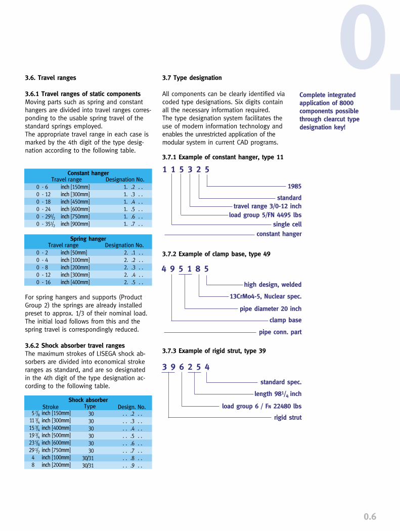
3.7 Type designation
All components can be clearly identified viacoded type designations. Six digits containall the necessary information required. The type designation system facilitates theuse of modern information technology andenables the unrestricted application of themodular system in current CAD programs.
3.7.1 Example of constant hanger, type 11
3.7.2 Example of clamp base, type 49
3.7.3 Example of rigid strut, type 39
Complete integrated application of 8000 components possiblethrough clearcut type designation key!
Travel range
0 - 6 inch [150mm]0 - 12 inch [300mm]0 - 18 inch [450mm]0 - 24 inch [600mm]0 - 291/2 inch [750mm]0 - 351/2 inch [900mm]
Constant hangerDesignation No.
1. .2 . .1. .3 . .1. .4 . .1. .5 . .1. .6 . .1. .7 . .
Travel range
0 - 2 inch [50mm]0 - 4 inch [100mm]0 - 8 inch [200mm]0 - 12 inch [300mm]0 - 16 inch [400mm]
Spring hangerDesignation No.
2. .1 . .2. .2 . .2. .3 . .2. .4 . .2. .5 . .
Stroke57/8 inch [150mm]
113/4 inch [300mm]153/4 inch [400mm]193/4 inch [500mm]235/8 inch [600mm]291/2 inch [750mm]4 inch [100mm]8 inch [200mm]
Type
303030303030
30/3130/31
Shock absorberDesign. No.
. . .2 . .
. . .3 . .
. . .4 . .
. . .5 . .
. . .6 . .
. . .7 . .
. . .8 . .
. . .9 . .
1985
standard
single cellconstant hanger
high design, welded
13CrMo4-5, Nuclear spec.
clamp base
pipe conn. part
standard spec.
length 981/4 inch
rigid strut
3 9 6 2 5 4
4 9 5 1 8 5
load group 6 / FN 22480 lbs
load group 5/FN 4495 lbstravel range 3/0-12 inch
pipe diameter 20 inch
1 1 5 3 2 5
0.7
Digit1
Productgroup
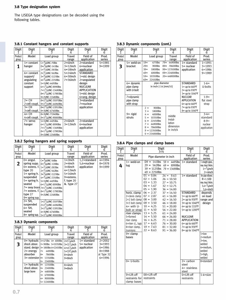
1
3.8.1 Constant hangers and constant supportsDigit
2Model
1= constanthanger
6= constantsupport/angulatingconstantsupport
2= CH2-cell coupl.3= CH3-cell coupl.4= CH4-cell coupl.7= servohanger
Digit3
Load group
C=3/8UNC-70lbs
D=3/8UNC-141lbs
1=1/2UNC-281lbs
2=1/2UNC-562lbs
3=5/8UNC-1125lbs
4=3/4UNC-2250lbs
5=1UNC-4495lbs
6=11/4UNC-8990lbs
7=11/2UNC-13490lbs
8=13/4UNC-17985lbs
9=2UNC-22480lbs
8=21/4UNC-35970lbs
9=21/2UNC-44960lbs
8=23/4UNC-53955lbs
9=3UNC-67400lbs
8=3UNC-71940lbs
9=31/4UNC-90000lbs
5=1UNC-4495lbs
6=11/4UNC-8990lbs
7=11/2UNC-13490lbs
8=13/4UNC-17985lbs
9=2UNC-22480lbs
Digit4
Travelrange
2=6inch3=12inch4=18inch5=24inch6=30inch7=36inch
2=6inch3=12inch
Digit5
Field ofapplication
2=standard6=nuclearapplicationSTANDARD1=std. design2=angulateddesignNUCLEARAPPLICATION5=std. design6=ang. design3=standard7=nuclearapplication
2=standard6=nuclearapplication
Digit6
Prod.series
5=19859=1999
Digit1
Productgroup
2
3.8.2 Spring hangers and spring supportsDigit
2Model
0= angul.spring supp.0= extens. f.type 201= spring h.suspended5= spring h.seated7= sway brace7= extens. f.type 279= spring sup.2= SH, suspended6= SH, seated8= spring sup.
Digit3
Load group
C=3/8UNC-56lbs
D=3/8UNC-120lbs
1=1/2UNC-281lbs
2=1/2UNC-562lbs
3=5/8UNC-1125lbs
4=3/4UNC-2250lbs
5=1UNC-4495lbs
6=11/4UNC-8990lbs
7=11/2UNC-13490lbs
8=13/4UNC-17985lbs
9=2UNC-22480lbs
1=21/4UNC-35970lbs
2=21/2UNC-44960lbs
3=23/4UNC-53955lbs
4=3UNC-67400lbs
5=31/4UNC-90000lbs
Digit4
Travelrange
1=2inch2=4inch3=8inch4=12inch5=16inch9=extens.f. type 20&. type 27
Digit5
Field ofapplication
1,2=standard5,6=nuclearapplication
Digit6
Prod.series
4=19948=19789=1999
Digit1
Productgroup
4
3.8.4 Pipe clamps and clamp basesDigit
2Model
1= weld-onlug
horiz. clamp2=clevis clamp2=2 bolt clamp3=3 bolt clamp4= with U-bolt or strapriser clamps5=formedriser clamp6=riser cl., lugs8=riser clamp,trunnions9= clampbases
0= U-bolts
9=Lift-offrestraints for clamp bases
Digit3+4
D9 = 141lbs 29 = 562lbs39 = 1125lbs49 = 2250lbs01 = 0.8402 = 1.0603 = 1.3304 = 1.6705 = 1.9006 = 2.3707 = 2.8708 = 3.0009 = 3.5010 = 4.2511 = 4.5013 = 5.2514 = 5.5016 = 6.2517 = 6.6319 = 7.6322 = 8.63
00=Lift-offrestraints
59 = 4495lbs69 = 8990lbs79 = 13490lbs
24 = 9.6326 = 10.5027 = 10.7532 = 12.7536 = 14.0037 = 14.5041 = 16.0042 = 16.5046 = 18.0051 = 20.0056 = 22.0061 = 24.0066 = 26.0071 = 28.0076 = 30.0081 = 32.0091 = 36.00
Digit5
Field ofapplication
1= standard
1= standard
STANDARD1= up to 660°F2= up to 930°F3= up to 1040°F4= up to 1110°F5= up to 1200°F
NUCLEARAPPLICATION6= up to 660°F7= up to 930°F8= up to 1040°F
2= carbonsteel4= stainlesssteel0=Lift-offrestraints
Digit6
Prod.series
f. straight pipes,max. insul. thickn.
1=3/8inch2=4inch
for pipe elbowsR�1.5OD
max. insul. thickn.3,4=3/8inch5,6=4inch
dependson load
range anddesign
1=low2=medium3=low, welded4=medium,welded 5=high,welded 8=standard
1-4=size
Pipe diameter in inch
Digit1
Productgroup
3
3.8.3 Dynamic components (cont.)Digit
2Model
5= weld-onbracket
6= dynamicpipe clampwith U-bolt
7=dynamicpipe clampwith strap
9= rigidstruts
Digit3
Load group
Digit4
Travelrange
Digit5
Field ofapplication
1= standard5= nuclearapplication
STANDARD1= up to 660°F2= up to 930°F3= up to 1040°FNUCLEARAPPLICATION6= up to 660°F7= up to 930°F8= up to 1040°F
Digit6
Prod.series
1=19913=19936=19869=1989
1-6=U-bolts
1-9=flat steel
strap
3-4=standard
8-9=nuclear
application
19= 675lbs 79= 44900lbs
29= 900lbs 89= 78600lbs
39= 1800lbs 99= 123500lbs
49= 4000lbs 09= 224000lbs
59= 10350lbs 20= 448000lbs
69= 22450lbs
pipe diameter
in inch·2.54 [mm/10]
2 = 900lbs
3 = 1800lbs
4 = 4000lbs
5 = 10350lbs
6 = 22450lbs
7 = 44900lbs
8 = 78600lbs
9 = 123500lbs
0 = 224000lbs
Digit1
Productgroup
3
3.8.3 Dynamic componentsDigit
2Model
0= hydraulicshock absor.stand. design2= energyabsorber3= extension
1= hydraulicshock absor.large bore
Digit3
Load group
1= 675lbs 4= 4000lbs
2= 900lbs 5=10350lbs
3= 1800lbs 6=22450lbs
7= 44900lbs
8= 78600lbs
9= 123500lbs
0= 224000lbs
9= 123500lbs
0= 224000lbs
2= 448000lbs
3= 670000lbs
4= 900000lbs
5= 1124000lbs
Digit4
Travelrange
2=57/8inch3=113/4inch4=153/4inch5=193/4inch8=4inch9=8inch
8=4inch9=8inch
Digit5
Field ofapplication
1= standard5= nuclearapplication
Digit6
Prod.series
2=20023=19936=19868=1988
at Type 326=1996
3.8 Type designation system
The LISEGA type designations can be decoded using thefollowing tables.
middleinstal-lationdimensionin inch/4
0.8
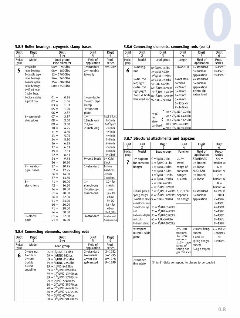
Digit1
Productgroup
6
3.8.6 Connecting elements, connecting rods (cont.)Digit
2Model
3=hexag.nut
5=tie rodleft/right6=tie rodright/right7=stud bolt/threaded rod
Digit3
Load group
D=3/8UNC-141lbs
2=1/2UNC-562lbs
3=5/8UNC-1125lbs
4=3/4UNC-2250lbs
5=1UNC-4495lbs
6=11/4UNC-8990lbs
7=11/2UNC-13490lbs
8=13/4UNC-17985lbs
9=2UNC-22480lbs
Digit4
Length
9 (Model 3)
1=not stan-
dardized
2=24inch
3=48inch
4=72inch
5=96inch
6=120inch
7=144inch
Digit5
Field ofapplication
1=standard
6=nuclear
application
2=standard
6=nuclear
application4=hot dipgalvanized
Digit6
Prod.-series
3=19938=19789=1999
Digit1
Productgroup
5
3.8.5 Roller bearings, cryogenic clamp basesDigit
2Model
1=cylinder roller bearings2=double taperroller bearings3=double cylinderroller bearings5=lift-off restr.f. roller bear.4=pipe saddle/support tray
6= preinsul-
ated pipes
7= weld-onpipe bases
8=stanchions
8=elbowpads
Digit3+4
Load groupPipe diameter
04= 900lbs
08= 1800lbs
12= 27000lbs
16= 3600lbs
35= 7870lbs
60= 13500lbs
01 = 0.8402 = 1.0603 = 1.3305 = 1.9006 = 2.3707 = 2.8708 = 3.0009 = 3.5010 = 4.2511 = 4.5013 = 5.2514 = 5.5016 = 6.2517 = 6.6319 = 7.6322 = 8.6324 = 9.6326 = 10.5027 = 10.7532 = 12.7536 = 14.0037 = 14.5041 = 16.0042 = 16.5046 = 18.0051 = 20.0056 = 22.0061 = 24.0066 = 26.0071 = 28.0076 = 30.0081 = 32.0091 = 36.00
Digit5
Field ofapplication
1=standard
2=movablelaterally
1=weldable2=with pipeclamp3=supportplate1=
12inch long
2,4,6=
20inch long
9=cold block
1=standard
1=stanchions2=telescopicstanchions
3=standard
Digit6
Prod.-series
9=1989
Insul. thickn.0=1inch
1=11/2inch
2=2inch
3=3inch
4=4inch
5=5inch
6=6inch
7=7inch
8=8inch
9=10inch
1= ColdBlock1=from T-sections2=from C-sections
1,2= forstreightpipes
3,4= forelbowR� OD5,6= forelbow
R�1,5OD1=carbon steel
2=stainless steel
10 = 21/4UNC-35970lbs
20 = 21/2UNC-44960lbs
30 = 23/4UNC-53955lbs
40 = 3UNC-67400lbs
50 = 31/4UNC-90000lbs
length
not
stan-
dardized{
Digit1
Productgroup
6
3.8.6 Connecting elements, connecting rodsDigit
2Model
0=eye nut1=clevis2=turn-buckle4=rod coupling
Digit3+4
D9 = 3/8UNC-141lbs29 = 1/2UNC-562lbs39 = 5/8UNC-1125lbs49 = 3/4UNC-2250lbs59 = 1UNC-4495lbs69 = 11/4UNC-8990lbs79 = 11/2UNC-13490lbs89 = 13/4UNC-17985lbs99 = 2UNC-22480lbs10 = 21/4UNC-35970lbs20 = 21/2UNC-44960lbs30 = 23/4UNC-53955lbs40 = 3UNC-67400lbs50 = 31/4UNC-90000lbs
Digit5
Field ofapplication
2=standard6=nuclear4=hot dipgalvanized
Digit6
Prod.-series
2=19825=19958=19789=1999
Load group
9=trapeze0=PTFE slideplate
7=connec-ting plate
2=2 con-nections3=3 con-nections1...3= travelrange ofspring han-ger 2-8 inch
4, 6 and 9=U-sections
7=L-sections
2=const.hang.trapeze1 and 2=spring hangertrapeze3=rigid trapeze
Digit1
Productgroup
7
3.8.7 Structural attachments and trapezesDigit
2Model
1= support
for constant
hanger
2=base plate f.spring hanger3=weld-on clevis4=weld-on plate5=weld-on eyenut6=beam adapterand bolts8=beam clamp
Digit3
Load group
C = 3/8UNC-70lbs
D = 3/8UNC-141lbs
1 = 1/2UNC-281lbs
2 = 1/2UNC-562lbs
3 = 5/8UNC-1125lbs
4 = 3/4UNC-2250lbs
5 = 1UNC-4495lbs
6 = 11/4UNC-8990lbs
7 = 11/2UNC-13490lbs
8 = 13/4UNC-17985lbs
9 = 2UNC-22480lbs
10 = 21/4UNC-35970lbs
20 = 21/2UNC-44960lbs
30 = 23/4UNC-53955lbs
40 = 3UNC-67400lbs
50 = 31/4UNC-90000lbs
Digit4
Function
2...7=travel
range of
constant
hanger
6-36inch
1, 2, 3, 9=depends
on design
Digit6
Prod.-series
5,9 =bracket 1x
6 =
bracket 2x7 =
bracket 3x8 =
bracket 4x1=1991/
20012=19823=19934=19945=19856=19968=19789=1989
Digit5
Field ofapplication
STANDARD
6= bolted
7= loose
NUCLEAR
8= bolted
9= loose
1=standard
5=nuclear
application
0
3rd to 6th digits correspond to clamps to be coupled

The following codes apply:MSS SP 58 Pipe supports - material and design USAMSS SP 69 Pipe supports - applications USAANSI ASME B31.1 Pressure piping systems USAASME III Div.I - NF Supports for nuclear components USAVGB-R 510 L Standard supports GermanyDIN 18800 Steelwork GermanyKTA 3205.1/2/3 Nuclear regulations GermanyAD-Merkblätter Working group for pressure vessels GermanyTRD-Regel Techn. regulations, steam boilers GermanyBS 3974 Pipe supports UKRCC-M Specifications for pipe supports FranceMITI 501 Technical regulations JapanJEAG 4601 Nuclear design regulations Japan
0.9
5. MATERIALSMaterials are exclusively used which corres-pond to ASTM material requirements andDIN or DIN-EN norms.
As a matter of principle, only materials ofguaranteed strength properties are used forsupporting components.
6. QUALIFICATION LEVELS FOR STANDARD ANDNUCLEAR APPLICATIONStandard supports have the same functionboth in the conventional and in the nuclearfield of application, and therefore do not
differ in design. Due to additional quality-assuring measures and materials with spe-cial certification, separate manufacture is how-ever necessary.
4. STANDARDS AND CALCULATIONSIn design, stress and load calculations, aswell as in manufacturing, the relevant Germanand international standards, technical regu-lations and codes are taken into account.
The characteristic values of materials that alldesign calculations are based on are takenfrom the relevant standards and recognizedtechnical codes.
Worldwide coverage of recognized codes and standards!
Standardized selection of high temperature materials!
MEANS OF CONNECTION
1.00381.00381.00381.05701.05701.05701.02541.03051.54151.73351.73801.49031.4301
1.7225
1.49031.77091.49231.7258
�660
xxxxxxxxxxxxx
xxxxxx
S235JRG2S235JRG2S235JRG2S355J2G3S355J2G3S355J2G3P235T1P235G11TH
16Mo 313CrMo 4-510CrMo 9-10X10CrMoVNb9-1X5CrNi 18-10
42CrMoV 4
X10CrMoVNb9-121 CrMoV 5-7X22CrMoV12-124CrMo 5
Temperature of medium in °F
A 36A 515 Gr. 60A 675 Gr. 55A 675 Gr. 70A 299A 516 Gr. 70A 53 S Gr. A
A 53 S Gr. A
A 204A 387 Gr. 12A 387 Gr. 22A 387 Gr. 91 Cl.II
A 312 TP 304
A 193 B7A 193 B8A 182 F91
A 194 Gr. 2H
�840
xxxxx
xxxxx
�930
xxxxx
xxxxx
�985
xxxx
xxxxx
�1040
xxx
xxxxx
�1110
xx
xx
x
�1200
x
xx
x
COMPONENTS
MaterialEN Material-No. EN 10027-2 ASTM
5.1 Preferred materials for pipe connection parts
0.10
0In the field of nuclear application, all mate-rials are traceable right through to the finishedproduct via heat number restamping, and thecomponents themselves are marked accor-ding to ASME and KTA regulations. In thetype designation, the nuclear design is notedin the 5th digit (for struts, the 6th digit). Therelevant component documentation relatesto this and to the fabrication order number.
In this catalog, the standard design, i.e. non-nuclear applications, provides the basis forthe type designations. As the given function-al data and unit dimensions are the same fornuclear applications, selection can also bemade here with the help of the catalog. On planning or ordering, attention must how-ever be paid to corresponding conformity ofthe type designations. The table showing thetype designation system (3.8, page 0.7) can beconsulted in this respect.
7. WELDINGAll welding is carried out as gas metal arcwelding - in special cases by stick welding.LISEGA holds certifications according to:
➜ ASME III Div I NCA NPT stamp➜ DIN EN 729-2 by the German TÜV➜ AD-HPO, production and testing of
pressure vessels, by the TÜV➜ DIN 18800 T7 Extended suitability
certification for steelwork and bridge construction by the SLV, the training and testing institute for welding technology
LISEGA welding inspection personnel are qua-lified according to ASME III NCA 4000 NF,DIN EN 719, AD HP3 and HP4. Non-destructive tests are carried out by testingstaff qualified acc. to ASME IX and DIN EN473, level 2, and SNT-TC-1A, level II.
Supporting connections are produced corres-ponding to the material group by qualifiedwelders according to ASME IX or DIN EN287, part 1. The welding procedure is quali-fied according to ASME IX and DIN EN 288.
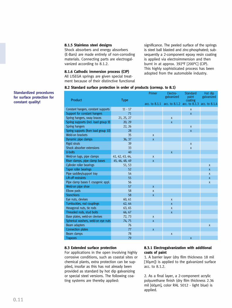
8. SURFACE TREATMENT
8.1 Standard coating systemsThe surfaces of LISEGA products are protectedas standard from corrosive influences by highquality protection systems that are also sui-table for external use in aggressive conditions(coastal, industrial and chemical areas). The following coating systems are applied to the different products:
8.1.1 Primer coatingComponents that are either to be welded to existing structure in the plant or simplyrequire higher quality transport protection arecoated on a bright metal surface with wel-dable primer (thickness app. 1.18 mil [30µm],color reddish brown).
8.1.2 ElectrogalvanizingSpring hangers and supports up to load size9, as well as all threaded parts and specialfunction parts, are electrogalvanized (zincthickness app. 0.59 mil [15µm], yellow chro-matized).UNC threaded parts are white chromatized.
8.1.3 Paint coatingsConstant hangers and supports and otherproducts according to table 8.2 receive thefollowing surface treatment:
1. Steel grit blasting according to SP-6 orSP-10 for the U.S. and EN ISO 12944-4grade SA 2 1/2 for Europe.
2. Undercoat of 1-component polyurethanezinc dust primer, dry film thickness 2.36 mil[60µm], approx. 62% zinc in solid statevolume, color grey.
3. Final coating of 2-component acrylic poly-urethane paint, dry film thickness 2.36 mil[60µm], color RAL 5012, light blue.
The total dry film thickness of the systemamounts to approx. 4.72 mil [120µm].
8.1.4 Hot dip galvanizationRoller bearings, pipe saddles and cryogenicpipe clamp bases are hot dip galvanized asstandard, zinc thickness approx. 2.36 mil[60µm].
Separate manufacture of products for nuclearapplications for the traceability of qualified materials!
0.11
Product Type
Standardpaint
coatingacc. to 8.1.3
Electro-galvanized
acc. to 8.1.2
Primer
acc. to 8.1.1
Hot dipgalvanized
acc. to 8.1.4
11 - 1771
21, 25, 2720, 2922, 26
2835
36, 37393340
41, 42, 43, 44, 45, 46, 48, 49
51, 5352545556575858
60, 6162, 6463, 6566, 6772, 73 74, 75
76777879
Constant hangers, constant supportsSupport for constant hangersSpring hangers, sway bracesSpring supports (incl. load group 9)Spring hangersSpring supports (from load group 10)Weld-on bracketsDynamic pipe clampsRigid strutsShock absorber extensionsU-boltsWeld-on lugs, pipe clampsRiser clamps, pipe clamp basesCylinder roller bearingsTaper roller bearingsPipe saddles/support trayLift-off restraintsPipe clamp bases f. cryogenic appl.Weld-on pipe shoeElbow padsStanchionsEye nuts, clevisesTurnbuckles, rod couplingsHexagonal nuts, tie rodsThreaded rods, stud boltsBase plates, weld-on clevisesSpherical washers, weld-on eye nutsBeam adaptersConnection platesBeam clampsTrapezes
xx
xx
xx
x
xx
x
xxxx
x
xx
xx
xxx
xx
x
xxxxx
x
8.2 Standard surface protection in order of products (corresp. to 8.1)
8.3 Extended surface protectionFor applications in the open involving highlycorrosive conditions, such as coastal sites orchemical plants, extra protection can be sup-plied, insofar as this has not already beenprovided as standard by hot dip galvanizingor special steel versions. The following coa-ting systems are thereby applied:
8.3.1 Electrogalvanization with additionalcoats of paint1. A barrier layer (dry film thickness 18 mil[30µm]) is applied to the galvanized surfaceacc. to 8.1.2.
2. As a final layer, a 2-component acrylicpolyurethane finish (dry film thickness 2.36mil [60µm], color RAL 5012 - light blue) isapplied.
8.1.5 Stainless steel designsShock absorbers and energy absorbers (E-Bars) are made entirely of non-corrodingmaterials. Connecting parts are electrogal-vanized according to 8.1.2.
8.1.6 Cathodic immersion process (CIP)All LISEGA springs are given special treat-ment because of their distinctive functional
significance. The peeled surface of the springsis steel ball blasted and zinc-phosphated; sub-sequently a 2-component epoxy resin coatingis applied via electroimmersion and thenburnt in at approx. 392°F [200°C] (CIP). This highly sophisticated process has beenadopted from the automobile industry.
Standardized proceduresfor surface protection forconstant quality!
0.12
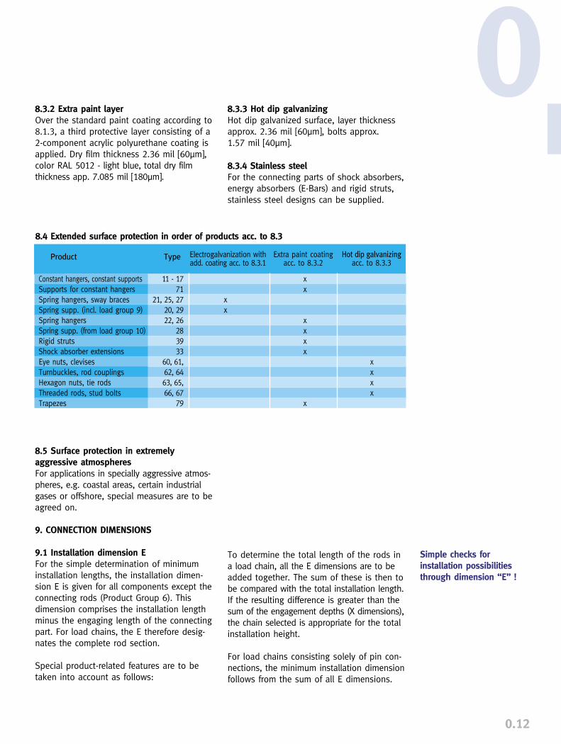
Product Type Extra paint coatingacc. to 8.3.2
Hot dip galvanizingacc. to 8.3.3
11 - 1771
21, 25, 2720, 2922, 26
283933
60, 61, 62, 6463, 65, 66, 67
79
Constant hangers, constant supportsSupports for constant hangersSpring hangers, sway bracesSpring supp. (incl. load group 9)Spring hangersSpring supp. (from load group 10)Rigid strutsShock absorber extensionsEye nuts, clevisesTurnbuckles, rod couplingsHexagon nuts, tie rodsThreaded rods, stud boltsTrapezes
xx
xxxx
x
Electrogalvanization withadd. coating acc. to 8.3.1
xx
xxxx
8.4 Extended surface protection in order of products acc. to 8.3
8.5 Surface protection in extremely aggressive atmospheresFor applications in specially aggressive atmos-pheres, e.g. coastal areas, certain industrialgases or offshore, special measures are to beagreed on.
9. CONNECTION DIMENSIONS
9.1 Installation dimension EFor the simple determination of minimuminstallation lengths, the installation dimen-sion E is given for all components except theconnecting rods (Product Group 6). Thisdimension comprises the installation lengthminus the engaging length of the connectingpart. For load chains, the E therefore desig-nates the complete rod section.
Special product-related features are to betaken into account as follows:
0
To determine the total length of the rods ina load chain, all the E dimensions are to beadded together. The sum of these is then tobe compared with the total installation length.If the resulting difference is greater than thesum of the engagement depths (X dimensions),the chain selected is appropriate for the totalinstallation height.
For load chains consisting solely of pin con-nections, the minimum installation dimensionfollows from the sum of all E dimensions.
8.3.3 Hot dip galvanizingHot dip galvanized surface, layer thicknessapprox. 2.36 mil [60µm], bolts approx. 1.57 mil [40µm].
8.3.4 Stainless steelFor the connecting parts of shock absorbers,energy absorbers (E-Bars) and rigid struts,stainless steel designs can be supplied.
Simple checks for installation possibilitiesthrough dimension “E” !
8.3.2 Extra paint layerOver the standard paint coating according to8.1.3, a third protective layer consisting of a2-component acrylic polyurethane coating isapplied. Dry film thickness 2.36 mil [60µm],color RAL 5012 - light blue, total dry filmthickness app. 7.085 mil [180µm].

0.13
Sensible devices on handfor readjusting installationlengths!
9.2 Regulation of the total installationlength
9.2.1 Turnbuckle function of the connectingthreadsFor length adjustment in installation condition(adjustment of pipe installation position, ac-tuation of loading), the lower connections inconstant and spring hangers provide a turn-buckle function. This way, subsequent adjust-ment of the installation lengths (attachmentrods) within a sufficient range is possible:
➜ for constant hangers type 11, by 113/4 inch [300mm]
➜ for spring hangers type 21, by the adjustment possibility of a turnbuckle, type 62
➜ for spring hangers type 22, by min. 51/2 inch [140mm]
➜ for spring hangers types 25 and 26, the load bearing rod is fed through the weld-on support tube and fixed with an adjustment nut. The adjustment can be made within the scope of the avai-lable threaded length of the rod.
All connection threads are supplied as righthand threads.
9.2.2 Spring supportsFor spring supports types 28 and 29, theinstallation height can be regulated by thesupport tube, functioning as a spindle inde-pendently of the presetting. The necessary load is actuated on installationby screwing the support tube upwards.
9.2.3 Turnbuckle, type 62, tie rod, lefthand/right hand thread, type 65For rigid hanging support arrangements withshort installation lengths, a defined reservelength in the connection parts type 60 and61 usually enables sufficient length adjust-ment. For longer installation lengths, the useof a turnbuckle L/R, type 62, in conjunctionwith a tie rod L/R, type 65, is appropriate.For easy access, this combination should bearranged at the lower end of the load chain.
9.2.4 Rigid struts, type 39The connections in rigid struts type 39 aresupplied as left/right, with fine threading forlength adjustment in the installation conditionas standard.Flat faces on the body of the rigid struts en-able simple adjustment with a wrench.
10. OPERATIONAL BEHAVIOR
10.1 FunctionConstant hangers type 1 are designed so thatin theory no load deviation occurs over thewhole range of action. The total deviationresulting from springs, bearing friction, andfabrication tolerances is held to within � 5%in series production. The load adjustment follows with a level ofaccuracy of 2%.
For spring hangers and supports, the loadalters linearly corresponding to the springtravel. The deviation of the spring force fromtheoretical values, resulting from spring hys-teresis and fabrication tolerances, amounts toless than � 5% within the ordered travel.
FN = nominal loadF min = min. load (upwards)F max = max. load (downwards)SN = nominal travel (incl. reserve)
FN = nominal loadSN = nominal travel (incl. reserve)S = operating travel
load
Flo
ad F
travel s
travel s
operating load
0.14
0measures are prescribed. They are an integralpart of order processing and embrace thewhole LISEGA group.
11.2 Quality management program, QMPThe QMP is clearly laid out in a quality ma-nagement manual, QMM, and regulates all thequality-assuring activities in the company.The QMM covers the organization as a whole,whereby the observance of rules is monitoredby the independent quality management de-partment QM. The QMM has been compiledaccording to international quality norms andstandards and specifically takes into accountthe regulations according to ASME III - NCA3800 and NCA 4000 incl. NF as well as DINEN ISO 9001 and KTA 1401.
The QMM applies in principle to both the con-ventional and nuclear fields. The extent ofmonitoring of materials and tests, as well asthe documentation, can in each case be exactly adapted to special requirements by theuse of extended QA levels. All internationalrequirements concerning nuclear applicationscan be covered. Corresponding qualificationsare available and are regularly renewed.
Certifying body
Lloyd’s Register QAL’AFAQASME Accreditation andCertificationASME Accreditation andCertificationTÜV Nord e.V.(independent Germanauthority)SLV-Hannover
TRACTEBEL (Vincotte)DET NORSKE VERITASNUPIC
Certification No.
Reg.Nr. 2005501996/5030N-2951
QSC 552
0121WO2978407-702-019407-703-008060317/62/9804
No. 1606No. DNV 5477CEXO-99/00210
Certification code
DIN/EN/ISO 9001DIN/EN/ISO 9001ASME-III NCA 4000/NF(NPT-Stamp)ASME-III NCA 3800/NF
Stamping agreementAD-Merkblatt HP 0; HP 3; HP 4Welding certification according to EN 729-2DIN 18800T7 Major qualification certificateASME III - NCA/NF; ASME IXSKIFS 1994:1ASME-III NF/NCA 3800;10CFR50 App. B; 10CFR21;N45.2; NQA1
11.3 International qualifications
QMP and Processing constitute a single entity!
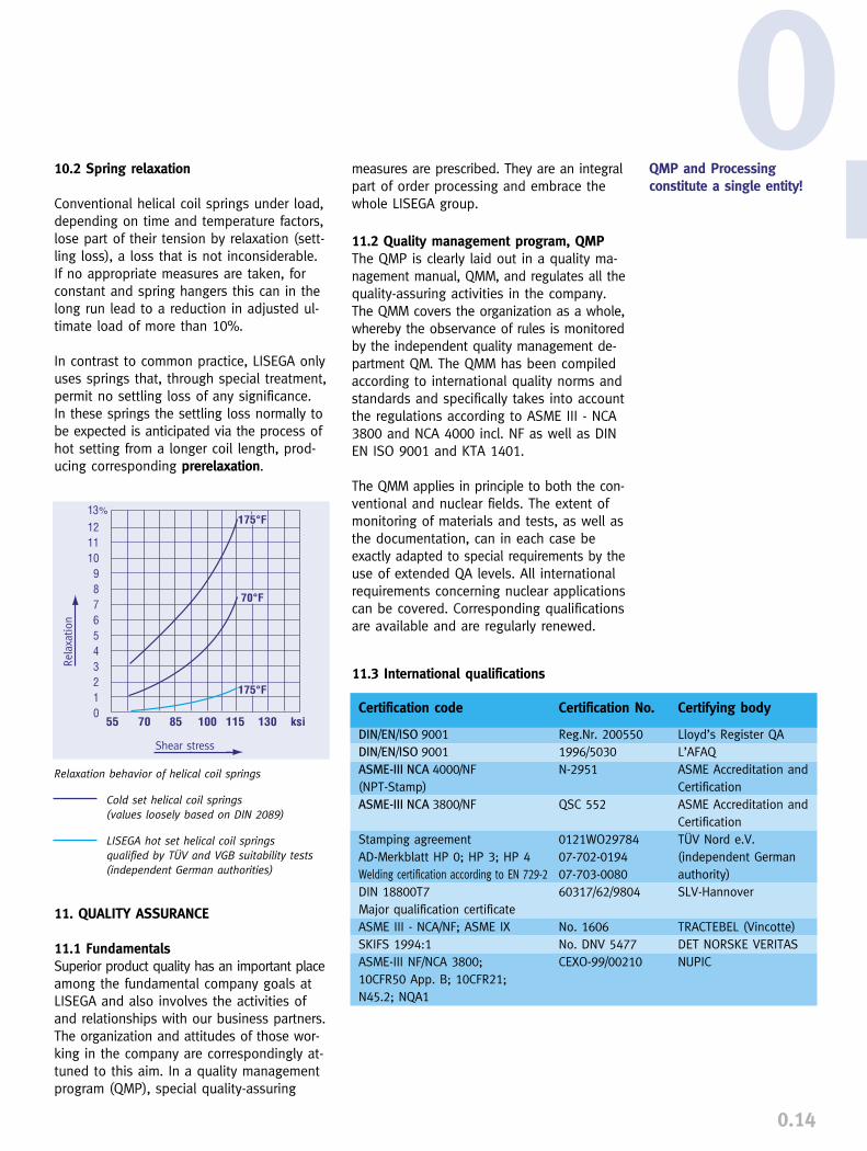
10.2 Spring relaxation
Conventional helical coil springs under load,depending on time and temperature factors,lose part of their tension by relaxation (sett-ling loss), a loss that is not inconsiderable.If no appropriate measures are taken, forconstant and spring hangers this can in thelong run lead to a reduction in adjusted ul-timate load of more than 10%.
In contrast to common practice, LISEGA onlyuses springs that, through special treatment,permit no settling loss of any significance. In these springs the settling loss normally tobe expected is anticipated via the process ofhot setting from a longer coil length, prod-ucing corresponding prerelaxation.
11. QUALITY ASSURANCE
11.1 FundamentalsSuperior product quality has an important placeamong the fundamental company goals atLISEGA and also involves the activities ofand relationships with our business partners.The organization and attitudes of those wor-king in the company are correspondingly at-tuned to this aim. In a quality managementprogram (QMP), special quality-assuring
Relaxation behavior of helical coil springs
Cold set helical coil springs(values loosely based on DIN 2089)
LISEGA hot set helical coil springs qualified by TÜV and VGB suitability tests(independent German authorities)
Rela
xatio
n
Shear stress

11.4 Tests and qualifications
11.4.1 Raw material and material receptionAll materials used undergo receiving controlby the quality management department. Thematerials used are qualified, correspondingto requirements by material tests accordingto ASME and DIN EN 10204.
11.4.2 Monitoring of manufactureManufacture is monitored via accompanyingquality control according to the QM manual.
In particular, for nuclear applications thequality-assuring requirements according toASME III NF and KTA are fulfilled.
11.4.3 Final inspectionBefore shipment, constant and spring hangersas well as shock absorbers undergo a func-tion test on test benches by quality manage-ment personnel. The tests are carried outusing computer-assisted equipment. Thevalues measured can be recorded by meansof a diagram. In addition, for constant andspring hangers the digital values can beprinted out over the whole travel range.
The specific test benches employed undergoregular inspections by an independent super-visory body.
11.4.4 Documentation on shipmentIf so ordered, the materials used are docum-ented by certification from material tests ac-cording to ASME and DIN EN 10204. In addit-ion, the results of the function tests can beconfirmed by issuing an acceptance test certificate, also from a supervisory body ifdesired.
0.15
Stress reports according to particular specif-ications and quality-assuring documents canbe agreed between customer, manufacturerand supervisory body.
11.5 Suitability test according to KTA 3205.3and type test according to VGB R 510 L
For the use of series-made standard supportsin conventional power plants, a type test by asupervisory body (according to § 14 of theappliance safety law GSG) is foreseen in theVGB code R 510 L.
For use in nuclear installations a correspon-ding suitability test, according to directive 35of the TÜV’s nuclear technology supervisorybody at the Vd TÜV, is prescribed by nuclearcode KTA 3205.3.
The test program prescribed comprises inessence the following components:
➜ inspection of the quality management program
➜ inspection of material used
➜ inspection of the design documentation
➜ inspection of design report summaries
➜ experimental function tests
➜ experimental overload tests
➜ experimental testing of continuous load capacity
For the broad range of LISEGA products, typeand suitability tests have been conductedby the German TÜV and VGB and the corres-ponding permits granted. Qualifications canbe supplied on request
Proven operational safetyand long life through typeand suitability tests!

0.16
12. FORM OF SHIPMENTAll components are shipped in appropriatepackaging for transport and short-term stor-age. They are clearly marked and, if required,protected through special preventive meas-ures against corrosive influences.
Special features are noted in the type datasheets or installation instructions. By specialorder, complete pipe support arrangements(load chains from different components) arepreassembled, bundled and labelled foridentification.
13. WARRANTYFor all LISEGA components a two-year war-ranty is issued from date of commissioningor for 8,000 hours of operation, limited tofour years after commissioning. For thenumber of hours of operation the plantrecords are applicable; the duration of thewarranty is limited to a maximum of fiveyears after shipment.
14. TECHNICAL MODIFICATIONSLISEGA expressly reserves the right to intro-duce modifications in the interests of furthertechnical development.
0
CONSTANT HANGERS, CONSTANT SUPPORTS
PRODUCT GROUP
1

1.0
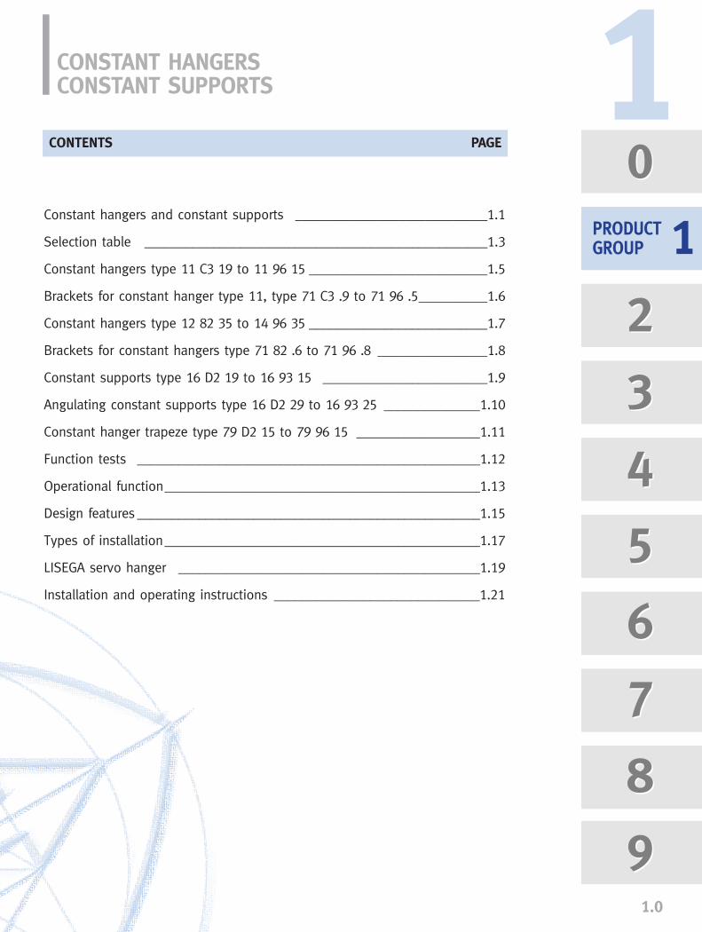
CONSTANT HANGERSCONSTANT SUPPORTS
Constant hangers and constant supports ____________________________1.1
Selection table __________________________________________________1.3
Constant hangers type 11 C3 19 to 11 96 15 __________________________1.5
Brackets for constant hanger type 11, type 71 C3 .9 to 71 96 .5__________1.6
Constant hangers type 12 82 35 to 14 96 35 __________________________1.7
Brackets for constant hangers type 71 82 .6 to 71 96 .8 ________________1.8
Constant supports type 16 D2 19 to 16 93 15 ________________________1.9
Angulating constant supports type 16 D2 29 to 16 93 25 ______________1.10
Constant hanger trapeze type 79 D2 15 to 79 96 15 __________________1.11
Function tests __________________________________________________1.12
Operational function______________________________________________1.13
Design features __________________________________________________1.15
Types of installation______________________________________________1.17
LISEGA servo hanger ____________________________________________1.19
Installation and operating instructions ______________________________1.21
CONTENTS PAGE
0
2
3
4
5
6
7
8
9
0
2
3
4
5
6
7
8
9
PRODUCTGROUP
11

CONSTANT HANGERS, CONSTANT SUPPORTS, PRODUCT GROUP 1
1.1
To avoid detrimental constraints in the system,thermal expansion in piping and other plantcomponents must not be prevented.
Constant hangersConstant hangers compensate for verticalmovement caused by thermal expansion. Via constant hangers, the respective pipingloads are constantly absorbed and transferredwith no significant deviation over the wholerange of movement.
Significant deviations would act as harmfuland uncontrolled extra loads in the system.
In this case, connection points are especiallyat risk because of unacceptable forces andmoments. It is vital that the constant hangers workreliably and efficiently, as this is decisive forthe operational safety and long life of thepiping system.
Constant hangers - the LISEGA systemFor nearly forty years LISEGA constant hangershave proven themselves convincingly in allkinds of operating conditions. The specialfunctional principle, based on the parallelogramof forces, is patented worldwide and hasfundamental significance in this respect.
Continued development of LISEGA constanthangers on this foundation has led to ma-tured products of superior quality with world-wide recognition.
See the sections “Operational Function”,page 1.13 and “Design Features”, page 1.15,in this regard.
▲ Constant hanger type 11 52 15
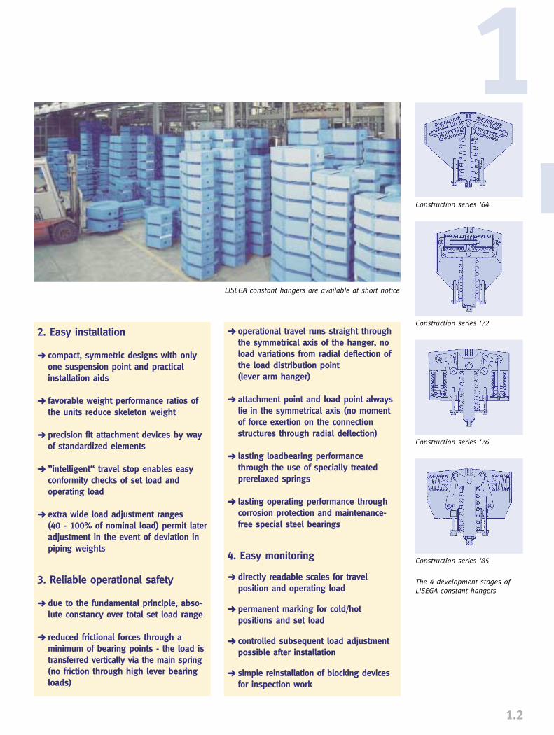
LISEGA constant hangers installed
For the user, the following features of LISEGAconstant hangers provide special benefits:
1. Simple planning
➜ standard cover for the respective load spectrum 0.05 - 500kN, travel range up to 900mm
➜ easy selection via load groups and travel ranges
➜ clearly arranged type identification system facilitates orientation
➜ symmetric and particularly compact designs of low installed weight
➜ user-friendly planning documentation, such as informative catalogs, technical manuals and special publications
➜ efficient LICAD design software, the special planning system for LISEGA standard supports
➜ optimum fit within installation environ-ment via standard variants and acces-sories (e.g. constant hangers suspended,seated, as supports or trapezes)
➜ only one load connection point for thesteel structure is needed
2. Easy installation
➜ compact, symmetric designs with only one suspension point and practical installation aids
➜ favorable weight performance ratios of the units reduce skeleton weight
➜ precision fit attachment devices by way of standardized elements
➜ ”intelligent“ travel stop enables easy conformity checks of set load and operating load
➜ extra wide load adjustment ranges (40 - 100% of nominal load) permit lateradjustment in the event of deviation in piping weights
3. Reliable operational safety
➜ due to the fundamental principle, abso-lute constancy over total set load range
➜ reduced frictional forces through a minimum of bearing points - the load is transferred vertically via the main spring(no friction through high lever bearing loads)
➜ operational travel runs straight through the symmetrical axis of the hanger, no load variations from radial deflection of the load distribution point (lever arm hanger)
➜ attachment point and load point always lie in the symmetrical axis (no moment of force exertion on the connection structures through radial deflection)
➜ lasting loadbearing performance through the use of specially treated prerelaxed springs
➜ lasting operating performance through corrosion protection and maintenance-free special steel bearings
4. Easy monitoring
➜ directly readable scales for travel position and operating load
➜ permanent marking for cold/hot positions and set load
➜ controlled subsequent load adjustment possible after installation
➜ simple reinstallation of blocking devicesfor inspection work
1.2
Construction series ‘64
Construction series ‘72
Construction series ‘76
Construction series ‘85
The 4 development stages ofLISEGA constant hangers
1
LISEGA constant hangers are available at short notice

750
700
650
600
550
500
450
400
350
300
250
200
150
100
50
0
0 0.625 1.25 2.5 5 10 15 20 30 40 50 60 70 80 90 100 120 140
SELECTION TABLE
1.3
Constant hangers, constant supports �
Trav
el (
mm
)
Load (kN)
11 1511 2511 3511 4511 5511 6511 7511 8511 9512 8512 9513 8513 9514 8514 95
11 6611 7611 8611 9612 8612 9613 8613 9614 8614 96
11 1411 2411 3411 4411 5411 6411 7411 8411 9412 8412 9413 8413 9414 8414 94
–11 D211 1211 2211 3211 4211 5211 6211 7211 8211 9212 8212 9213 8213 9214 8214 92
0.130.250.501.002.004.008.00
16.0024.0032.0040.0064.0080.0096.00
120.00128.00160.00
135
270
405
540
675
0.140.270.541.082.174.338.67
17.3326.0034.6643.3369.3386.66
104.00130.00138.70173.30
140
280
420
560
700
0.150.290.581.172.334.669.33
18.6628.0037.3346.6674.6693.30
112.00140.00149.30186.70
145
290
435
580
725
0.160.310.631.252.505.00
10.0020.0030.0040.0050.0080.00
100.00120.00150.00160.00200.00
150
300
450
600
750
0.170.330.671.332.675.33
10.6721.3332.0042.6653.3385.33
106.70128.00160.00170.70213.30
145
290
435
580
725
0.180.350.711.422.835.66
11.3322.6634.0045.3356.6690.66
113.30136.00170.00181.30226.70
140
280
420
560
700
0.190.380.751.503.006.00
12.0024.0036.0048.0060.0096.00
120.00144.00180.00192.00240.00
135
270
405
540
675
0.200.400.791.583.176.33
12.6725.3338.0050.6663.33
101.30126.70152.00190.00202.70253.30
130
260
390
520
650
0.220.440.881.753.507.00
14.0028.0042.0056.0070.00
112.00140.00168.00210.00224.00280.00
120
240
360
480
600
Type description Load (kN)
�
�
�
�
�
�� 0.21
0.420.831.663.336.66
13.3326.6640.0053.3366.66
106.66133.30160.00200.00213.30266.70
125
250
375
500
625
11 C311 D311 1311 2311 3311 4311 5311 6311 7311 8311 9312 8312 9313 8313 9314 8314 93
Selection
example:
24 kN / 210mm
Intermediate
values can be
interpolated
...2..(150mm)
...3..(300mm)
...4..(450mm)
...5..(600mm)
...6..(750mm)
1.4
750
700
650
600
550
500
450
400
350
300
250
200
150
100
50
0
60 80 100 125 150 175 200 225 250 275 300 325 350 375 400 500 600
1Tr
avel
(m
m)
Load (kN)
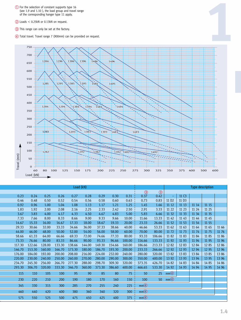
� For the selection of constant supports type 16 (see 1.9 and 1.10 ), the load group and travel range of the corresponding hanger type 11 apply.
� Loads � 0.25kN or 0.13kN on request.
� This range can only be set at the factory.
� Total travel. Travel range 7 (900mm) can be provided on request.
11 1511 2511 3511 4511 5511 6511 7511 8511 9512 8512 9513 8513 9514 8514 95
11 6611 7611 8611 9612 8612 9613 8613 9614 8614 96
11 1411 2411 3411 4411 5411 6411 7411 8411 9412 8412 9413 8413 9414 8414 94
11 C311 D311 1311 2311 3311 4311 5311 6311 7311 8311 9312 8312 9313 8313 9314 8314 93
–11 D211 1211 2211 3211 4211 5211 6211 7211 8211 9212 8212 9213 8213 9214 8214 92
mm�
mm�
0.230.460.921.833.677.33
14.6729.3344.0058.6673.33
117.30146.70176.00220.00234.70293.30
115
230
345
460
575
0.240.480.961.923.837.66
15.3330.6646.0061.3376.66
122.66153.30184.00230.00245.30306.70
110
220
330
440
550
0.250.501.002.004.008.00
16.0032.0048.0064.0080.00
128.00160.00192.00240.00256.00320.00
105
210
315
420
525
0.260.521.042.084.178.33
16.6733.3350.0066.6683.33
133.30166.70200.00250.00266.70333.30
100
200
300
400
500
0.270.541.082.164.338.66
17.3334.6652.0069.3386.66
138.66173.30208.00260.00277.30346.70
95
190
285
380
475
0.280.561.132.254.509.00
18.0036.0054.0072.0090.00
144.00180.00216.00270.00288.00360.00
90
180
270
360
450
0.290.581.172.334.679.33
18.6737.3356.0074.6693.33
149.30186.70224.00280.00298.70373.30
85
170
255
340
425
0.300.601.212.424.839.66
19.3338.6658.0077.3396.66
154.66193.30232.00290.00309.30386.60
80
160
240
320
400
0.310.631.252.505.00
10.0020.0040.0060.0080.00
100.00160.00200.00240.00300.00320.00400.00
75
150
225
300
375
0.420.831.663.336.66
13.3326.6653.3380.00
106.66133.33213.33266.66320.00400.00426.70533.30
25
50
Load (kN)
0.370.731.452.915.83
11.6623.3346.6670.0093.33
116.66186.66233.33280.00350.00373.35466.65
50
100
mm�
mm�
mm�
� �
Type description

CONSTANT HANGER TYPE 11
1.5
Constant hangerType 11 C3 19 to 11 96 15Series-made standarddesign, available from stock.
� Installation dimension Eapplies to the uppermost block-ing position.In other positions, E increases accordingly.
� X = minimum thread engagement.On lower connection max thread engagement = X + 300mm.
Order details:Constant hangertype 11 .. ..Marking:…Operating load: …kNTravel: …mm up/downBlocking position (if required):
A
350300410385415435465445460480530445490525595500570610665590710745845725815845885
1145780850
100011601275815945
111012001260865
1095124012551305
Type
11 C3 1911 D2 1911 D3 1911 12 1511 13 1511 14 1511 15 1511 22 1511 23 1511 24 1511 25 1511 32 1511 33 1511 34 1511 35 1511 42 1511 43 1511 44 1511 45 1511 52 1511 53 1511 54 1511 55 1511 62 1511 63 1511 64 1511 65 1511 66 1511 72 1511 73 1511 74 1511 75 1511 76 1511 82 1511 83 1511 84 1511 85 1511 86 1511 92 1511 93 1511 94 1511 95 1511 96 15
B
130110130130130130135160160160165170170170170185185185190230230230230275275275275280300300300305305320320320320325350350350355355
C
150155170140140140150180185185195190190190200220220220240270270285285335335345345345380380400400400390390400420420435435455455455
D
10586
106106106106108132132132136132132132136150150150154190190190190230230230230232252252252256256256256256256260276276276280280
d2
M10M10M10M12M12M12M12M12M12M12M12M16M16M16M16M20M20M20M20M24M24M24M24M30M30M30M30M30M36M36M36M36M36M42M42M42M42M42M48M48M48M48M48
d5
9111112121212121212121212121216161616202020202525252525353535353535353535353535353535
d6
Ø 9Ø11Ø11M10M10M10M10M10M10M10M10M10M10M10M10M12M12M12M12M16M16M16M16M16M16M16M16M16M20M20M20M20M20M20M20M20M20M20M24M24M24M24M24
Weight(kg)
1410191525345221354875274361
101446692
15073
115159212134183264337495195262378550690263364509731965336475677862
1130
E�
530350545375645935
1225385650945
1215390675970
1255440740
10701370470770
11051405555900
128516302030610945
137517102150705
1140164520852585760
1190173521602700
X�
15151515151515151515152020202025252525303030303535353535454545454550505050506060606060
H
455250445265445615795270455635810275470650830315495675855345515705880420565750925
1330455635785975
1425585715925
11151625630785960
10901620
L
250230260285285285295350360360370360360360370400410410420490490490490580580600600600650650650660660650650670690690750750770770770
O
400
4525202525204545251070505025
110556530
105756040
16015012015550
14019565
21050
21530512525050
250380250290
P
265195280135270325450140270320460165260365465260250370540210285410530240300355460650285300400665710330340390740850350355380585800
Q
24012525540
16522535045
19524536530
18026537013521027545570
21531041585
260310380600110205360490675115280420595825135325480570820
R
4343438686868686868686
112110110110105105105105115126126135145145149149149170170179184184200200200200200195195195195195

� The 5th digit of the type des-cription indicates the design:6 for brackets bolted on,
standard specification.7 for loose brackets,
standard specification.8 for brackets bolted on,
nuclear specification.9 for loose brackets,
nuclear specification.
� E in the uppermost blockingposition. In other positions, Edecreases accordingly.
� Constant hangers can be seated directly on the structureand welded in place. When doingthis, care must be taken to provideaccess to the adjusting screws andlock nut. If this access cannot be provided,type 71 brackets should be used.
Order details:Constant hanger type 11 .. .. with bracket type 71 .. .. Marking:Operating load: …kN,Travel: …mm up/downBlocking position (if required):
BRACKETS FOR CONSTANT HANGER TYPE 11
1.6
Brackets for constanthanger type 11type 71 C3 .9 to 71 96 .5Series-made standard design available from
stock.The brackets can be supplied ac-cording to require-ments, either shopfitted or supplied separately for sub-sequent fitting on site.
1Lug for transport
Base plate
Detail Z
Const h. Brackets WeightType Type� A1 B1 C d4 E� F G1 K1 L M N T U y (kg)
11 C3 19 71 C3 .9 420 70 150 12 265 40 810 355 250 395 - 6 60 14 511 D2 19 71 D2 .9 370 70 155 12 145 40 510 260 230 345 - 6 60 14 511 D3 19 71 D3 .9 480 70 170 12 265 40 825 380 260 455 - 6 60 14 811 12 15 71 12 .5 495 115 140 12 145 60 535 270 285 440 50 8 100 14 1211 13 15 71 13 .5 525 115 140 12 265 60 925 480 285 470 50 8 100 14 1711 22 15 71 22 .5 575 140 180 12 145 75 545 275 350 505 65 8 120 14 1511 23 15 71 23 .5 590 140 185 12 265 75 930 475 360 520 65 8 120 14 2111 32 15 71 32 .5 575 140 190 12 150 75 560 285 360 505 70 10 120 18 1611 33 15 71 33 .5 620 140 190 12 270 75 965 495 360 550 70 10 120 18 2311 34 15 71 34 .5 655 140 190 12 390 75 1380 730 360 585 70 10 120 18 3211 35 15 71 35 .5 725 140 200 12 510 75 1785 955 370 655 70 10 120 18 4011 42 15 71 42 .5 640 160 220 14 155 80 620 305 400 570 80 10 140 18 1811 43 15 71 43 .5 710 160 220 14 275 80 1040 545 410 640 80 10 140 18 2911 44 15 71 44 .5 750 160 220 14 395 80 1490 815 410 680 80 10 140 18 4111 45 15 71 45 .5 805 160 240 14 515 80 1910 1055 420 735 80 10 140 18 4911 52 15 71 52 .5 750 200 270 18 160 90 660 315 490 670 110 12 180 18 3011 53 15 71 53 .5 870 200 270 18 280 90 1080 565 490 790 110 12 180 18 4211 54 15 71 54 .5 905 200 285 18 400 90 1535 830 490 825 110 12 180 18 5811 55 15 71 55 .5 1005 200 285 18 520 90 1955 1075 490 925 110 12 180 18 7211 62 15 71 62 .5 915 250 335 23 165 110 755 335 580 815 135 12 220 18 4511 63 15 71 63 .5 1005 250 335 23 285 110 1220 655 580 905 135 12 220 18 6211 64 15 71 64 .5 1035 250 345 23 405 110 1725 975 600 935 135 12 220 18 9011 65 15 71 65 .5 1075 250 345 23 525 110 2190 1265 600 975 135 12 220 18 11211 66 15 71 66 .5 1335 250 345 23 345 110 2410 1080 600 1235 135 12 220 18 11211 72 15 71 72 .5 980 270 380 27 175 115 830 375 650 875 135 15 240 18 5611 73 15 71 73 .5 1050 270 380 27 295 115 1285 650 650 945 135 15 240 18 8011 74 15 71 74 .5 1200 270 400 27 415 115 1835 1050 650 1095 135 15 240 18 10611 75 15 71 75 .5 1360 270 400 27 535 115 2290 1315 660 1255 135 15 240 18 12811 76 15 71 76 .5 1475 270 400 27 280 115 2475 1050 660 1370 135 15 240 18 12811 82 15 71 82 .5 1025 280 390 33 180 120 935 350 650 935 140 15 240 18 6511 83 15 71 83 .5 1155 280 390 33 300 120 1490 775 650 1065 140 15 240 18 9111 84 15 71 84 .5 1320 300 400 33 420 120 2115 1190 670 1230 140 15 260 18 13911 85 15 71 85 .5 1410 320 420 33 540 120 2675 1560 690 1320 140 15 280 18 18411 86 15 71 86 .5 1470 320 420 33 270 120 2905 1280 690 1380 140 15 280 18 18411 92 15 71 92 .5 1105 300 435 33 190 140 1010 380 750 995 140 20 260 18 8211 93 15 71 93 .5 1335 300 435 33 310 140 1560 775 750 1225 140 20 260 18 10911 94 15 71 94 .5 1480 320 455 33 430 140 2225 1265 770 1370 140 20 280 18 16211 95 15 71 95 .5 1495 340 455 33 550 140 2770 1680 770 1385 140 20 320 18 27311 96 15 71 96 .5 1545 340 455 33 260 140 3020 1400 770 1435 140 20 320 18 273

CONSTANT HANGERTYPE 12-14
1.7
Constant hangers type 12 82 35 to 14 96 35Standard design, multi-cellhanger.Assembly possible at shortnotice from stock units.
� Dimension E applies touppermost blocking position. For other positions E increasesaccordingly.
Order details:Constant hangertype 1. .. 35Marking:…Operating load: …kNTravel: …mm up/downBlocking position (if required):
WeightH L M N O P R R1max. S W (kg)
585 80 540 300 50 330 90 95 30 160 615715 80 540 300 215 340 90 95 30 160 820925 80 540 300 305 390 90 95 30 160 1110
1115 80 540 300 125 740 90 95 30 160 15551625 80 545 304 250 850 90 95 30 160 2020630 90 590 330 50 350 105 110 35 175 785785 90 590 330 250 355 105 110 35 175 1070960 90 590 330 380 380 105 110 35 175 1475
1090 90 595 334 250 585 105 110 35 175 18451620 90 595 334 290 800 105 110 35 175 2380585 80 840 2x300 50 330 105 125 35 210 955715 80 840 2x300 215 340 105 125 35 210 1265925 80 840 2x300 305 390 105 125 35 210 1700
1115 80 840 2x300 125 740 105 125 35 210 23701625 80 850 2x304 250 850 105 125 35 210 3070630 90 920 2x330 50 350 120 140 35 230 1215785 90 920 2x330 250 355 120 140 35 230 1640960 90 920 2x330 380 380 120 140 35 230 2245
1090 90 930 2x334 250 585 120 140 35 230 28101620 90 930 2x334 290 800 120 140 35 230 3615585 80 1140 3x300 50 330 120 180 35 250 1305715 80 1140 3x300 215 340 120 180 35 250 1715925 80 1140 3x300 305 390 120 180 35 250 2300
1115 80 1140 3x300 125 740 120 180 35 250 31901625 80 1150 3x304 250 850 120 180 35 250 4125630 90 1250 3x330 50 350 135 180 40 250 1665785 90 1250 3x330 250 355 135 180 40 250 2230960 90 1250 3x330 380 380 135 180 40 250 3040
1090 90 1260 3x334 250 585 135 180 40 250 37901620 90 1260 3x334 290 800 135 180 40 250 4870
Type A B C D d3 E�
12 82 35 860 635 390 555 60 120512 83 35 990 635 390 555 60 164012 84 35 1155 635 400 555 60 214512 85 35 1245 635 420 555 60 258512 86 35 1305 645 420 565 60 308512 92 35 910 695 435 605 70 131012 93 35 1140 695 435 605 70 174012 94 35 1285 695 455 605 70 228512 95 35 1300 705 455 615 70 271012 96 35 1350 705 455 615 70 325013 82 35 860 935 390 855 70 130513 83 35 990 935 390 855 70 174013 84 35 1155 935 400 855 70 224513 85 35 1245 935 420 855 70 268513 86 35 1305 950 420 870 70 318513 92 35 910 1025 435 935 80 142013 93 35 1140 1025 435 935 80 185013 94 35 1285 1025 455 935 80 239513 95 35 1300 1040 455 950 80 282013 96 35 1350 1040 455 950 80 336014 82 35 860 1235 390 1155 80 138514 83 35 990 1235 390 1155 80 182014 84 35 1155 1235 400 1155 80 232514 85 35 1245 1235 420 1155 80 276514 86 35 1305 1250 420 1170 80 326514 92 35 910 1355 435 1265 90 146014 93 35 1140 1355 435 1265 90 189014 94 35 1285 1355 455 1265 90 243514 95 35 1300 1375 455 1280 90 286014 96 35 1350 1375 455 1280 90 3400

BRACKETS FORCONSTANT HANGER TYPE 12-14
Brackets Type 71 82 .6 - 71 96 .8for constant hanger type 12 - 14Standard design.
The brackets are nor-mally shop assembled. On request they can be supplied loose forassembly on site.
� The 5th digit of the type des-cription indicates the specification:6 for brackets bolted on,
standard specification.7 for brackets loose,
standard specification.8 for brackets bolted on,
nuclear specification.9 for brackets loose,
nuclear specification.
� Dimensions E and G2 apply tothe uppermost position. In otherpositions E and G2 change accordingly.
Order details:Constant hanger type 1. .. ..with bracket type 71 .. ..bolted on.Marking:…Operating load: …kNTravel: …mm up/downBlocking position (if required):
1
1.8
Lug for transport
Detail Z
WeightG2� K1 M1 N T U Z (kg)
1095 350 935 300 15 240 300 1421530 775 1065 300 15 240 300 1942035 1190 1230 300 15 260 300 2922475 1560 1320 300 15 280 300 3832975 1280 1380 304 15 280 304 3831190 380 995 330 20 260 330 1811620 775 1225 330 20 260 330 2352165 1265 1370 330 20 280 330 3412590 1680 1385 334 20 320 334 5743130 1400 1435 334 20 320 334 5741145 350 935 300 15 240 600 2161580 775 1065 300 15 240 600 2942085 1190 1230 300 15 260 600 4402525 1560 1320 300 15 280 600 5763025 1280 1380 304 15 280 608 5761245 380 995 330 20 260 660 2761675 775 1225 330 20 260 660 3572220 1265 1370 330 20 280 660 5152645 1680 1385 334 20 320 668 8643185 1400 1435 334 20 320 668 8641185 350 935 300 15 240 900 2891620 775 1065 300 15 240 900 3922125 1190 1230 300 15 260 900 5872565 1560 1320 300 15 280 900 7693065 1280 1380 304 15 280 912 7701265 380 995 330 20 260 990 3691695 775 1225 330 20 260 990 4772240 1265 1370 330 20 280 990 6872665 1680 1385 334 20 320 1002 11533205 1400 1435 334 20 320 1002 1155
Const. h. BracketsType Type� A1 B1 C E� F G1
12 82 35 71 82 .6 1025 580 390 180 120 98512 83 35 71 83 .6 1155 580 390 300 120 154012 84 35 71 84 .6 1320 600 400 420 120 216512 85 35 71 85 .6 1410 620 420 540 120 272512 86 35 71 86 .6 1470 620 420 270 120 295512 92 35 71 92 .6 1105 630 435 190 140 106512 93 35 71 93 .6 1335 630 435 310 140 161512 94 35 71 94 .6 1480 650 455 430 140 228012 95 35 71 95 .6 1495 675 455 550 140 282512 96 35 71 96 .6 1545 675 455 260 140 307513 82 35 71 82 .7 1025 880 390 180 120 98513 83 35 71 83 .7 1155 880 390 300 120 154013 84 35 71 84 .7 1320 900 400 420 120 216513 85 35 71 85 .7 1410 920 420 540 120 272513 86 35 71 86 .7 1470 920 420 270 120 295513 92 35 71 92 .7 1105 960 435 190 140 106513 93 35 71 93 .7 1335 960 435 310 140 161513 94 35 71 94 .7 1480 980 455 430 140 228013 95 35 71 95 .7 1495 1010 455 550 140 282513 96 35 71 96 .7 1545 1010 455 260 140 307514 82 35 71 82 .8 1025 1180 390 180 120 98514 83 35 71 83 .8 1155 1180 390 300 120 154014 84 35 71 84 .8 1320 1200 400 420 120 216514 85 35 71 85 .8 1410 1220 420 540 120 272514 86 35 71 86 .8 1470 1230 420 270 120 295514 92 35 71 92 .8 1105 1290 435 190 140 106514 93 35 71 93 .8 1335 1290 435 310 140 161514 94 35 71 94 .8 1480 1310 455 430 140 228014 95 35 71 95 .8 1495 1340 455 550 140 282514 96 35 71 96 .8 1545 1340 455 260 140 3075

CONSTANT SUPPORTTYPE 16
Constant supporttype 16 D2 19 to 16 93 15Standard design
� Dimension E applies to theuppermost blocking positionand permits an adjustment tolerance of +60mm.
Order details:Constant support type 16 .. ..Marking: …Operating load: …kNTravel: …mm up/downBlocking position (if required):
1.9
For considerable horizontal load movement PTFE slide plates are recommended.(See also p. 2.1, type 29) �
øL1Type Loadgroup øL1
70 19 16 D, 1 4070 39 16 2, 3 4070 49 16 4 6570 59 16 5 6570 69 16 6 11070 79 16 7 11070 89 16 8 15070 99 16 9 150
WeightH K L M N O P S T (kg)
250 265 80 175 - - 195 6 6 15445 415 80 195 - 45 280 6 6 25265 270 80 210 50 25 135 6 8 23445 515 80 210 50 20 270 6 8 39270 270 100 260 65 20 140 6 8 33455 500 100 260 65 45 270 6 8 56275 275 100 270 70 10 165 6 10 39470 515 100 270 70 70 260 6 10 64315 280 120 300 80 25 260 8 10 59495 550 120 300 80 110 250 8 10 93345 280 150 380 110 30 210 10 12 96515 555 150 380 110 105 285 10 12 155420 285 170 450 135 40 240 10 12 164565 640 170 450 135 160 300 10 12 239455 320 200 515 135 50 285 12 15 236635 625 200 515 135 140 300 12 15 334585 300 200 490 140 50 330 15 15 306715 755 200 490 140 215 340 15 15 449630 320 240 570 140 50 350 20 20 388785 745 240 570 140 250 355 20 20 570
Type A A1 B B1 D d4 E � F
16 D2 19 300 240 110 70 86 12 710 4516 D3 19 410 260 130 70 106 12 1205 4516 12 15 385 275 130 115 106 12 730 6016 13 15 415 275 130 115 106 12 1300 6016 22 15 445 340 160 140 132 12 735 7516 23 15 460 340 160 140 132 12 1300 7516 32 15 445 350 170 140 132 12 745 7516 33 15 490 350 170 140 132 12 1330 7516 42 15 500 390 185 160 150 14 805 8016 43 15 570 390 185 160 150 14 1405 8016 52 15 590 480 230 200 190 18 835 9016 53 15 710 480 230 200 190 18 1435 9016 62 15 725 570 275 250 230 23 920 11016 63 15 815 570 275 250 230 23 1560 11016 72 15 780 640 300 270 252 27 990 11516 73 15 850 640 300 270 252 27 1625 11516 82 15 815 640 320 280 256 33 1100 12016 83 15 945 640 320 280 256 33 1835 12016 92 15 865 740 350 300 276 33 1170 14016 93 15 1095 740 350 300 276 33 1895 140
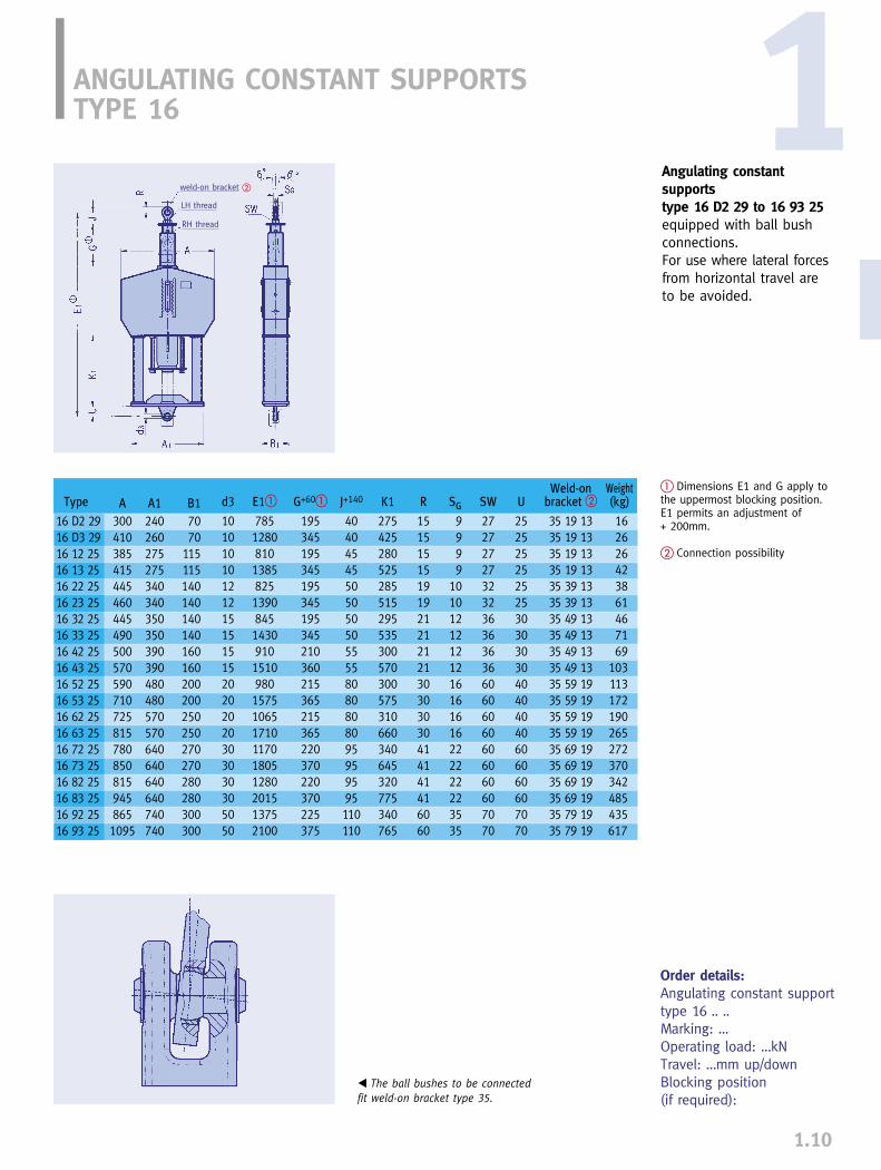
ANGULATING CONSTANT SUPPORTSTYPE 16
Angulating constant supportstype 16 D2 29 to 16 93 25equipped with ball bushconnections.For use where lateral forcesfrom horizontal travel areto be avoided.
1.10
� Dimensions E1 and G apply tothe uppermost blocking position.E1 permits an adjustment of + 200mm.
� Connection possibility
Order details:Angulating constant support type 16 .. ..Marking: …Operating load: …kNTravel: …mm up/downBlocking position (if required):
� The ball bushes to be connectedfit weld-on bracket type 35.
weld-on bracket �
LH thread
RH thread
Weld-on Weightd3 E1� G+60� J+140 K1 R SG SW U bracket � (kg)
10 785 195 40 275 15 9 27 25 35 19 13 1610 1280 345 40 425 15 9 27 25 35 19 13 2610 810 195 45 280 15 9 27 25 35 19 13 2610 1385 345 45 525 15 9 27 25 35 19 13 4212 825 195 50 285 19 10 32 25 35 39 13 3812 1390 345 50 515 19 10 32 25 35 39 13 6115 845 195 50 295 21 12 36 30 35 49 13 4615 1430 345 50 535 21 12 36 30 35 49 13 7115 910 210 55 300 21 12 36 30 35 49 13 6915 1510 360 55 570 21 12 36 30 35 49 13 10320 980 215 80 300 30 16 60 40 35 59 19 11320 1575 365 80 575 30 16 60 40 35 59 19 17220 1065 215 80 310 30 16 60 40 35 59 19 19020 1710 365 80 660 30 16 60 40 35 59 19 26530 1170 220 95 340 41 22 60 60 35 69 19 27230 1805 370 95 645 41 22 60 60 35 69 19 37030 1280 220 95 320 41 22 60 60 35 69 19 34230 2015 370 95 775 41 22 60 60 35 69 19 48550 1375 225 110 340 60 35 70 70 35 79 19 43550 2100 375 110 765 60 35 70 70 35 79 19 617
Type A A1 B116 D2 29 300 240 7016 D3 29 410 260 7016 12 25 385 275 11516 13 25 415 275 11516 22 25 445 340 14016 23 25 460 340 14016 32 25 445 350 14016 33 25 490 350 14016 42 25 500 390 16016 43 25 570 390 16016 52 25 590 480 20016 53 25 710 480 20016 62 25 725 570 25016 63 25 815 570 25016 72 25 780 640 27016 73 25 850 640 27016 82 25 815 640 28016 83 25 945 640 28016 92 25 865 740 30016 93 25 1095 740 300
1

CONSTANT HANGER TRAPEZE TYPE 79
1.11
Constant hanger trapezetype 79 D2 15 to 79 96 15This type of trapeze is usedin case of limited installationlength where the standardtrapeze type 79 .2 34 doesnot fit due to restrictedinstallation height.The trapezes are normallyshop assembled.
� X = minimum thread en-gagement, 300mm thread en-gagement possible.
� L and Z to be stated whenordering
� E and C apply to uppermostposition. In other positions Eand C increase accordingly.
� When selecting constant han-ger trapezes, their total weightmust be added to the opera-tional load.
� The permissible load reducesby 5% per 100mm of extendedlength.
Order details:Trapeze type 79 .. .. with 2 constant hangerstype 11 .. ..L= …mmZ= …mmMarking: …Operating load: …kN at the supporting point.Travel: …mm up/downBlocking position (if required):
Type
79 D2 1579 D3 1579 12 1579 13 1579 22 1579 23 1579 32 1579 33 1579 34 1579 35 1579 42 1579 43 1579 44 1579 45 1579 52 1579 53 1579 54 1579 55 1579 62 1579 63 1579 64 1579 65 1579 66 1579 72 1579 73 1579 74 1579 75 1579 76 1579 82 1579 83 1579 84 1579 85 1579 86 1579 92 1579 93 1579 94 1579 95 1579 96 15
A max.
12101230193019301960196021702170217021702185218521852190233023302330233023752375237523752380240024002400240524052420242024202420242524502450245024552455
B
325435515545575590605650685755640710750805740860895
1005895985
101510551315970
10401200136014751015114513101400146010651295144014551505
C�
365560390660400665410695990
1275465765
10951395500800
11351435590935
132016652065655990
142017552195755
1190169521352635820
1250179522202760
D
110130130130160160170170170170185185185190230230230230275275275275280300300300305305320320320320325350350350355355
E�
180245235380240355235370585765190415680800275420660845315480815
10851265320560820
10201275380650
101512751545430665
105513951680
G
151530303030454545455555555565656565707070707085858585859595959595
100100100100100
L max.�
11001100180018001800180020002000200020002000200020002000210021002100210021002100210021002100210021002100210021002100210021002100210021002100210021002100
Tot. wght. (kg) Wght. chang.X� L=1000 � (kg/m)�
15 30 6.615 48 6.615 61 23.815 81 23.815 74 23.815 103 23.820 104 36.420 137 36.420 174 36.420 255 36.425 153 44.025 199 44.025 253 44.025 370 44.030 230 50.630 318 50.630 408 50.630 528 58.835 384 66.435 486 66.435 650 66.435 798 66.435 1120 66.445 549 83.645 688 83.645 941 92.445 1296 92.445 1600 92.450 746 119.050 959 119.050 1263 119.050 1715 119.050 2190 119.060 908 119.060 1207 119.060 1625 119.060 1997 119.060 2530 119.0

FUNCTION TESTS 1
1.12
Specimen of atest certificatefrom a normaldelivery test
Functional performanceThe specific functional principle of LISEGA con-stant hangers guarantees absolute constancyacross the entire travel range. This is not evenaffected by load adjustment. Only a minorfriction force resulting from tolerances andbearings has to be taken into account as aslight deviation. The hysteresis produced bythis is kept within very narrow limits by thedesign principle and by state-of-the-art manu-facturing procedures.
For normal load settings, deviations in theoperating load for LISEGA constant hangersin series production is kept in practice at � 3% on average. Using a selection process,supply of hangers with a maximum deviationof � 2% is possible.
The generally permissible deviations are laiddown in the following international standards:
➜ MSS-SP 58, USA, max. � 6% referring to operating load.
➜ VGB R 510 L and KTA 3205.3, Germany, max. � 5% referring to operating load.
➜ EN Europa Normenentwurf, max � 5%, referring to operating load. The mean load deviation is limited to max � 2%.
Function testsBefore delivery, each constant hanger is testedfor correct function and set to the requiredload.
The test results are both graphically and digi-tally plotted and recorded. They can be sup-plied on request.
The load setting values are stamped on ariveted aluminum name plate. In addition,the set load is permanently marked on theload scale. Cold and hot positions are markedon the travel scale in white and red respec-tively.
The relevant travel position is directly read-able on the travel scale in mm and inches.The relevant set load can be read from theload scale in kN or lbs.
For function testing, quasistatically actingtest benches with a capacity of up to1000kN are available in all the factories. The test benches are inspected at regularintervals by an independent authority.
Acceptance test of a constant hanger

F
A
F1
B
E
C
D
F2
F
A
F1
B
D
C
E
F
A
B
C
D
E
F
� Operating function of LISEGA constant hanger
2
Upper position
Midposition
Lower position
OPERATIONAL FUNCTION
1.13
Special requirementsStrict demands are placed on constant han-gers to ensure reliable function:
➜ absolute constancy for all load settings
➜ minimum mechanical friction
Likewise, particular requirements are to befulfilled for the continuous monitoring of thepiping system performance:
➜ reliable indicators for set load and travel
➜ adequate and precise subsequent load adjustment if required
The LISEGA functional principleLISEGA’s patented functional principle forconstant hangers provides the ideal condi-tions for fulfilling all requirements. The prin-ciple is based on the interplay of force fromone main spring and the resultant forcefrom two hooked up compensating springs.The directions of force of the two pre-stressed compensating springs are opposedto each other in the form of a parallelogramof forces.
The suspended load acts directly on themain spring via a central load tube . The force of the compensating springs operates as resultant force , via camsand rollers . This force acts additionallyon the load tube. The main spring forceand resultant force change when the loadis moved over the travel range . This is inaccordance with the characteristics of thespring, and the angle and shape of the cams.The individual components are arranged insuch a way that any changes in the resultantspring constancy correspond exactly withthe characteristic curve of the main spring.In this way the force of the main spring isevenly compensated for, providing constantsupporting force.
FF2
AB
F
1
s
D
E
F2
C

Large loadadjustment range
Small number of unitsizes (load groups,modular system)
Serial production(favorable
manufacturing costs)
Warehousing(short term availability)
LISEGA functional principle for
constant hangers
1.14
1Down towards the apex of the cams theresultant force diminishes in proportion tothe increase in the relatively low startingforce of the main spring.
At the apex of the cams the forces of thecompensating springs are cancelled out. The resultant is zero. At this point only themain spring carries the load. Beyond the apex,the direction of the proportionally increasingresultant force of the compensating springs isreversed. It now reduces the relatively strongmain spring force in the same way.
The sum of, or the difference between theforces F1 and F2 at each point in the travelrange = F.
➜ Only the LISEGA functional principle guarantees absolute constancy right from a theoretical basis.
➜ Only the LISEGA functional principle allows a particularly wide load adjustmentrange of 40 - 100% of the nominal load.
Load adjustmentLoad adjustment is carried out by adjustingthe pre-tension of the main spring. Becausethe characteristic curves of the resultantcompensating force and those of the main-spring are identical, only a linear displace-ment of the starting load occurs. The forcevariation achieved by altering the main springpre-tension is the same at every point in themovement cycle. Therefore, the ultimate loadremains constant at each load setting. The
usable travel changes in proportion to theload alterations.
The extremely wide load adjustment rangeenables us to cover a broad range of appli-cations with a compact number of unit sizes.This special advantage is the prerequisite forthe formation of load groups as the basis ofthe LISEGA modular system. In this way,rational series production and warehousingcontrol are made possible.
� Effect of load adjustment in LISEGA constant hangers
➜➜
➜➜
Examples of practical functionF1
Travel

1.15
Connection typesThe connection threads correspond to thestandardized diameter of the relevant LISEGAload group. At the upper connection thethread depth is limited. At the lower end, thenut is used as a turnbuckle for adjusting rodlength.
The shape of the hanger housing allows directseating on existing connection structureswithout extra accessories. In addition, specialbrackets can be attached using the standardtapped holes provided. Constant hangersabove load group 9 (heavy duty) have yokeplates for bolted connections instead ofconnection threads.
Performance rangeConstant hangers and supports are manufac-tured in load groups C - 9 as serialized single-cell units. They can also be coupled togetherfor load groups 8 or 9 as multi-cell hangerswith heavier loads. In this way a standardized range of 0.1 kNto 500 kN can be covered. Constant hangersare manufactured in 6 standard travel ranges:150/ 300/ 450/ 600/ 750/900mm - constantsupports up to 300mm.
Standards and calculationsComponent design and layout fully complyas regards load capacity, dynamic functionand lifespan with the relevant national andinternational standards and codes. This ap-plies equally to the materials used, weldingtechnology and other processes. Relevantdetails can be found in the TechnicalSpecifications (page 0.9).
SpringsThe springs are decisive for the flawless functioning of constant hangers – the longterm operational safety of these componentsdepends on them. DIN standards form thebasis of the LISEGA coil spring specifications.Details can be found in the TechnicalSpecifications in section 0.
Mounted constant hanger
DESIGN FEATURES
Design shapeLISEGA constant hangers are made to a com-pact and symmetrical design. This facilitatesspace saving installation dimensions and theuse of standard accessories. When installingon site, much time and effort is saved bylow unit weight and simple positioning atconnection points. Only one hanging point isneeded for fitting. The load transfer passesthrough the axis of symmetry. Space for ra-dial deflection (lever arm hanger) need not beconsidered. Additional moments posed on thesupporting structure by lever arm units aretherefore avoided. The design enables a directreading of the travel position on a scale of 1:1.
Design constructionA steel housing encases the internal workingparts such as springs and cams. The compactarrangement of these individual parts insidethe housing leads to small external dimen-sions. The housing is designed to be loadbearing and to accommodate LISEGA standardconnecting components.
Type 79trapeze
Type 71bracket
Steel construction
on site
Type 66 rod
Type 61 clevis
Type 60 eyenut
Type 67 stud bolt
� Serial connection types
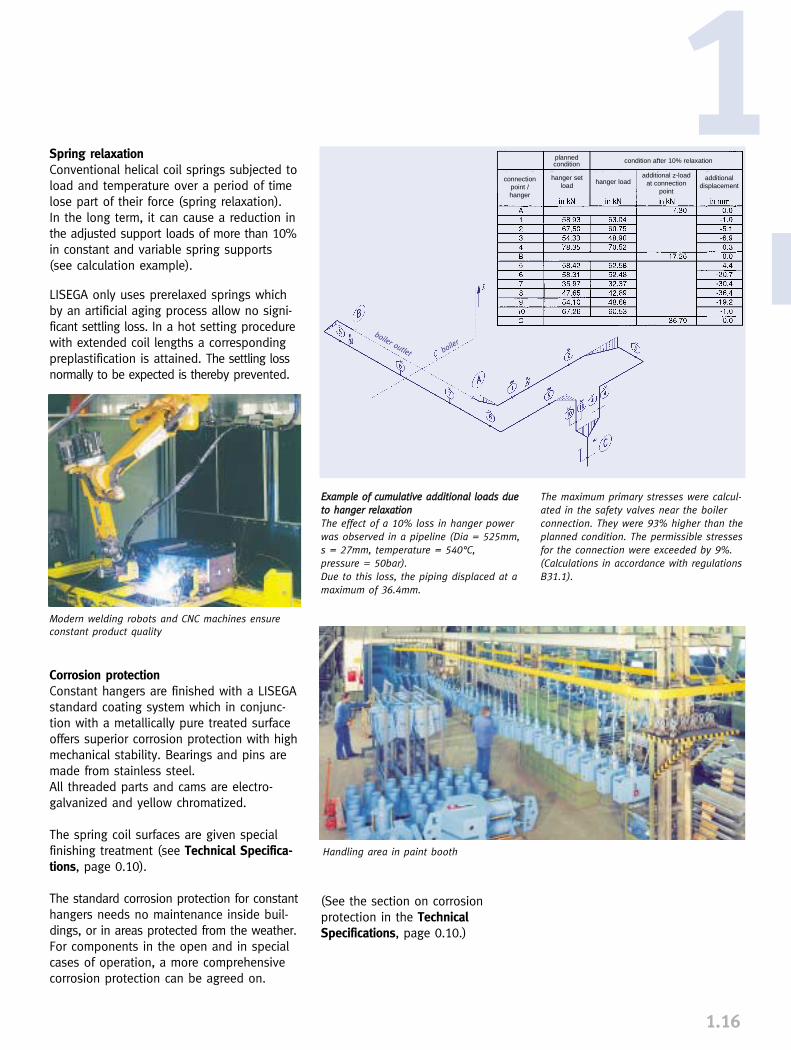
1.16
1
EExxaammppllee ooff ccuummuullaattiivvee aaddddiittiioonnaall llooaaddss dduueettoo hhaannggeerr rreellaaxxaattiioonnThe effect of a 10% loss in hanger powerwas observed in a pipeline (Dia = 525mm,s = 27mm, temperature = 540°C, pressure = 50bar).Due to this loss, the piping displaced at amaximum of 36.4mm.
The maximum primary stresses were calcul-ated in the safety valves near the boilerconnection. They were 93% higher than theplanned condition. The permissible stressesfor the connection were exceeded by 9%.(Calculations in accordance with regulationsB31.1).
Spring relaxationConventional helical coil springs subjected toload and temperature over a period of timelose part of their force (spring relaxation). In the long term, it can cause a reduction inthe adjusted support loads of more than 10%in constant and variable spring supports(see calculation example).
LISEGA only uses prerelaxed springs whichby an artificial aging process allow no signi-ficant settling loss. In a hot setting procedurewith extended coil lengths a correspondingpreplastification is attained. The settling lossnormally to be expected is thereby prevented.
Corrosion protectionConstant hangers are finished with a LISEGAstandard coating system which in conjunc-tion with a metallically pure treated surfaceoffers superior corrosion protection with highmechanical stability. Bearings and pins aremade from stainless steel. All threaded parts and cams are electro-galvanized and yellow chromatized.
The spring coil surfaces are given specialfinishing treatment (see Technical Specifica-tions, page 0.10).
The standard corrosion protection for constanthangers needs no maintenance inside buil-dings, or in areas protected from the weather.For components in the open and in specialcases of operation, a more comprehensivecorrosion protection can be agreed on.
Modern welding robots and CNC machines ensureconstant product quality
Handling area in paint booth
(See the section on corrosion protection in the TechnicalSpecifications, page 0.10.)
plannedcondition
connectionpoint / hanger
hanger setload
hanger load additional displacement
additional z-loadat connection
point
condition after 10% relaxation
boiler outlet boiler
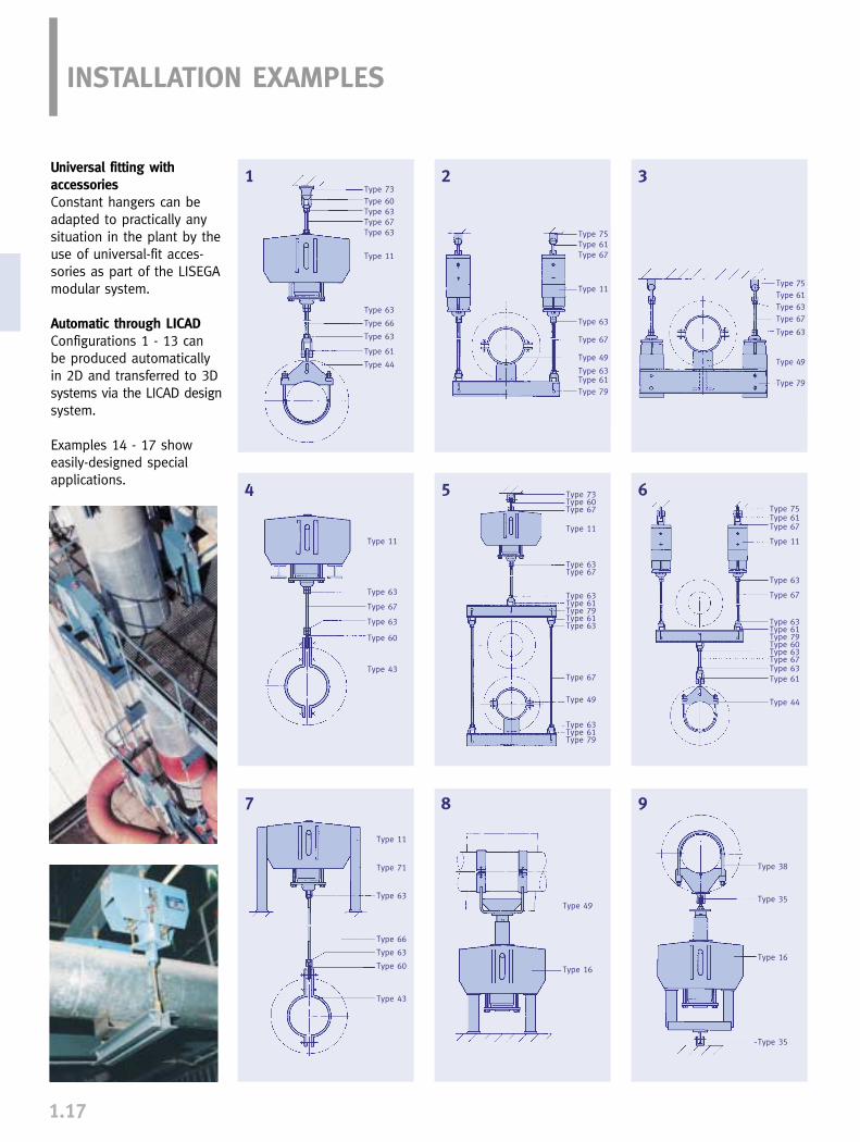
1.17
INSTALLATION EXAMPLES
Universal fitting with accessoriesConstant hangers can beadapted to practically anysituation in the plant by theuse of universal-fit acces-sories as part of the LISEGAmodular system.
Automatic through LICADConfigurations 1 - 13 can be produced automaticallyin 2D and transferred to 3Dsystems via the LICAD designsystem.
Examples 14 - 17 showeasily-designed special applications.
Typ 38
1 2 3
4 5 6
7 8 9
Type 73Type 60Type 63Type 67Type 63
Type 11
Type 63
Type 66
Type 63
Type 61
Type 44
Type 75Type 61Type 67
Type 11
Type 63
Type 67
Type 49
Type 63Type 61Type 79
Type 75Type 61Type 63Type 67
Type 63
Type 49
Type 79
Type 75Type 61Type 67
Type 11
Type 63
Type 67
Type 63Type 61Type 79Type 60Type 63Type 67Type 63Type 61
Type 44
Type 11
Type 63
Type 67
Type 63
Type 60
Type 43
Type 73Type 60Type 67
Type 11
Type 63Type 67
Type 63Type 61Type 79Type 61Type 63
Type 67
Type 49
Type 63Type 61Type 79
Type 11
Type 71
Type 63
Type 66
Type 63
Type 60
Type 43
Type 49
Type 16
Type 38
Type 35
Type 16
Type 35

1.18
1
17
10
14
12 1311
16
15
Typ 48
Type 73Type 60Type 67Type 61Type 79Type 61Type 63
Type 67
Type 63Type 61Type 79Type 61Type 63Type 67
Type 63
Type 11
Type 67Type 60
Type 43
Type 73Type 60Type 67
Type 11
Type 63Type 67Type 63Type 61Type 79Type 61Type 63
Type 67
Type 63Type 61Type 48
Type 73Type 60Type 63Type 66Type 63
Type 11
Type 63
Type 67
Type 63
Type 61
Type 46
Type 75Type 61Type 67
Type 11
Type 63
Type 66
Type 63
Type 61Type 48
Type 11
Type 63
Type 66
Type 63
Type 60
Type 43
Type 49
Type 16
Type 11
Type 49
Type 63
Type 67
Type 74Type 63
Type 71
Type 71
Type 11
Type 63
Type 67
Type 63
Type 61
Type 44
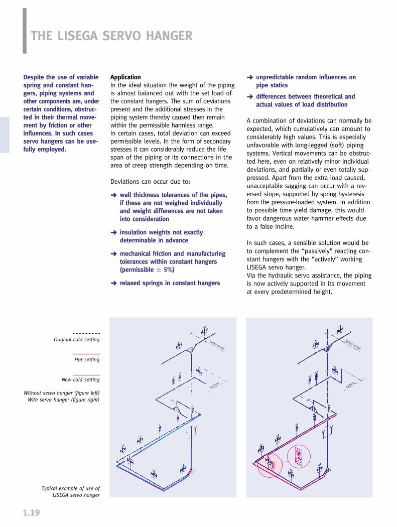
1.19
➜ unpredictable random influences on pipe statics
➜ differences between theoretical and actual values of load distribution
A combination of deviations can normally beexpected, which cumulatively can amount toconsiderably high values. This is especiallyunfavorable with long-legged (soft) pipingsystems. Vertical movements can be obstruc-ted here, even on relatively minor individualdeviations, and partially or even totally sup-pressed. Apart from the extra load caused,unacceptable sagging can occur with a rev-ersed slope, supported by spring hysteresisfrom the pressure-loaded system. In additionto possible time yield damage, this wouldfavor dangerous water hammer effects dueto a false incline.
In such cases, a sensible solution would beto complement the “passively” reacting con-stant hangers with the “actively” workingLISEGA servo hanger.Via the hydraulic servo assistance, the pipingis now actively supported in its movementat every predetermined height.
THE LISEGA SERVO HANGER
ApplicationIn the ideal situation the weight of the pipingis almost balanced out with the set load ofthe constant hangers. The sum of deviationspresent and the additional stresses in thepiping system thereby caused then remainwithin the permissible harmless range.In certain cases, total deviation can exceedpermissible levels. In the form of secondarystresses it can considerably reduce the lifespan of the piping or its connections in thearea of creep strength depending on time.
Deviations can occur due to:
➜ wall thickness tolerances of the pipes, if these are not weighed individually and weight differences are not taken into consideration
➜ insulation weights not exactly determinable in advance
➜ mechanical friction and manufacturing tolerances within constant hangers (permissible � 5%)
➜ relaxed springs in constant hangers
Original cold setting
Hot setting
New cold setting
Without servo hanger (figure left)With servo hanger (figure right)
Despite the use of variablespring and constant han-gers, piping systems andother components are, undercertain conditions, obstruc-ted in their thermal move-ment by friction or otherinfluences. In such casesservo hangers can be use-fully employed.
Typical example of use of LISEGA servo hanger
boiler center
turbine
turbine
boiler center

1.20
1Unit sizesUnits are available from series constructionfor load groups 5 (FN 20kN) to 9 (FN 100kN)with travel range 2 (150mm) and 3 (300mm).In special cases non-standard designs can bemanufactured.
Operating instructionsInstallation and commissioning instructionsand maintenance recommendations are sup-plied on delivery.
Design and functionThe basis for the servo hanger is a standardType 11 constant hanger. To overcome loaddifferences, it is additionally fitted with ahydraulic auxiliary device providing additionalactive force in both directions (servo assis-tance).
As a control parameter, the temperature ofthe piping to be supported is normally used.The relevant temperature is converted elec-tronically into the corresponding position. Inthe actual / theoretical value comparison pro-cedure, the control provides for a regulatedadvance towards the vertical theoreticalposition.
Electro-hydraulic controlThe hydraulic unit and the electronic controlare housed separately from each other in aswitchgear cabinet mounted near the servohanger (max distance 16m).The hydraulic piston controlling the move-ment is located in the load tube of the con-stant hanger.
Automatic safety switchThe electrohydraulic control is designed insuch a way that only the servo assistance islost if there is an operational breakdown, e.g. a power failure. The unit itself wouldcarry on operating in the normal way as aconstant hanger.For deviations in theoretical (temp.) / actual(travel) a tolerance range can be adjusted.The control shuts off automatically if thedeviation lies outside these values.
Manual shut offFor possible maintenance work in the systemor at the boiler, the servo assistance can beshut on or off by hand.
� See page 1.3 and 1.4 also
� 2 = Travel range 23 = Travel range 3
Function scheme
hydr.device
electr.control
theoretical
actual
Servo- Nominal Calibration � Load dependent travel � Additionalhanger load FN load Travel range 2 Travel range 3 Servo forceType � kN kN mm mm kN
17 5. 15 20 8 - 20 75 - 150 150 - 300 � 817 6. 15 40 16 - 40 75 - 150 150 - 300 � 2017 7. 15 60 24 - 60 75 - 150 150 - 300 � 2017 8. 15 80 32 - 80 75 - 150 150 - 300 � 2017 9. 15 100 40 - 100 75 - 150 150 - 300 � 20

1.21
On the name plate are stamped:
➜ type➜ serial number➜ order number (if required)➜ set load➜ theoretical travel➜ marking (position number)➜ test stamp (if required)
On the travel scale, the theoretical hot posi-tion is marked with a red sticker, the theo-retical cold position with a white one. The load adjustment ordered is permanentlystamped on the load scale with an X duringfinal inspection.
INSTALLATION ANDOPERATING INSTRUCTIONS
Constant hangers are mech-anically acting devices.Their trouble free operationis vitally important for thesafety of piping systemsand connected components.Careful attention must bepaid to the following in-structions to ensure troublefree operation.
1. Transport and storageTransport must be carried out carefully inorder to avoid damage. It is particularly im-portant that load adjustment screws andconnection threads remain intact. If storedin the open, care must be taken to protectcomponents from dirt and moisture.
2. Delivery conditionLISEGA constant hangers are supplied set tothe load specified in the order, and blockedin the required installation position. All han-gers are supplied with a riveted aluminumname plate, as well as travel and load scale.
� travel stop� guide bolt� name plate� red marking
for hot position� fixing bolt with
washer for travel stop after deblocking
� travel scale� serrated travel
stop strip adjustment load
indicator load scale� adjustment bolt� load tube control bore for min.
screw-in depth� load nut� upper yoke plate� lower yoke plate� connecting rod� tensioning bolt
��
�
��
��
�� �
�
�
�
�
�
�
�
�
�
�
Name plate with stamped operating data
Travel scale with cold/hot markings
Load scale with indicator
�
�
2.1 Constant hangertypes 11 C3 .. - 11 96 .. (single cell)The upper connection is supplied as internalthread with limited screw engagement. The lower connection is a spherical load nutwhich can angulate through a minimum of 4°in all directions. The connection threads arefilled with grease and sealed with plastic caps.

2.2 Constant hangertypes 12 82 - 14 96 (multi cells)The upper connection is provided as standardin the form of a lug for a connecting pin.The lower attachment exists of several ten-sioning bolts connected by a yoke plate.
2.3 Constant hangers (seated)Constant hangers of all sizes can be directlyseated. They can also be supplied with serial-ized brackets type 71. The brackets can bebolted on at works or on site according toorder using the precision fit holes provided.The base plates of the mountings can be eitherwelded or bolted to the mounting surface.
2.4 Constant supports type 16Constant supports follow the same designprinciple as the constant hanger. Instead ofthe lower connection, they have an uppersupport tube with a screwed-in adjustingspindle and load plate.
3. InstallationWhen installing, the rules for the InstallationInstructions for Piping are to be adhered to.Special attention must be paid to the desiredinstalled position of the hanger rods in thewhole support chain. Two possibilities areusual practice:
1. The hanger rods are to be installed at anangle in accordance with expected horizontaldisplacement of the piping. It is expected thatthe rods become vertical during operatingconditions.
2. The hanger rods are to be installed ver-tically for better control. A controlled angledposition during operating conditions is thenpermitted.
In all cases there should be a unified set ofrules for the whole plant.
Attachment rods and points must be connec-ted under actuation of load.
3.1 Constant hangertype 11 C3 - 11 96 (single cell)Transport lugs or other installation aids canbe screwed into the threaded holes providedon the sides. After deblocking the hangers(see Point 4), the blocking plates should bebolted on here for storage. For constanthangers with type 71 brackets, the hangersare supplied with transport lugs instead ofthe upper connection. The lugs can also ac-commodate the blocking plates. When rem-oving the blocking plates from constanthanger types 11 82 to 11 96, care must betaken that only the larger circlip is removed.For connection to the connecting rod, caremust be taken that the lower rod is screwedinto the load nut at least up to the controlbore. A further screw engagement of 300mmis provided.
1.22
1
� load plate� adjusting spindle� support tube� serrated travel
stop strip� blocking plate� name plate� guide pin travel scale securing screw &
washer for blockingplate after deblocking
� indicator for adjustment load
� load scale adjustment bolt
�
�
�
�
�
�
�
�
�
Blocking plate bolted laterally
Blocking pin with circlips
Constant support type 16
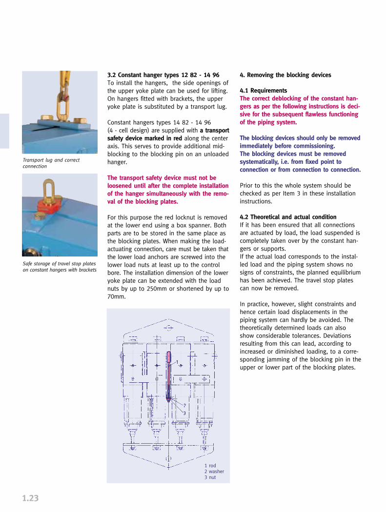
3.2 Constant hanger types 12 82 - 14 96To install the hangers, the side openings ofthe upper yoke plate can be used for lifting.On hangers fitted with brackets, the upperyoke plate is substituted by a transport lug.
Constant hangers types 14 82 - 14 96(4 - cell design) are supplied with a transportsafety device marked in red along the centeraxis. This serves to provide additional mid-blocking to the blocking pin on an unloadedhanger.
The transport safety device must not be loosened until after the complete installationof the hanger simultaneously with the remo-val of the blocking plates.
For this purpose the red locknut is removedat the lower end using a box spanner. Bothparts are to be stored in the same place asthe blocking plates. When making the load-actuating connection, care must be taken thatthe lower load anchors are screwed into thelower load nuts at least up to the controlbore. The installation dimension of the loweryoke plate can be extended with the loadnuts by up to 250mm or shortened by up to70mm.
1.23
4. Removing the blocking devices
4.1 RequirementsThe correct deblocking of the constant han-gers as per the following instructions is deci-sive for the subsequent flawless functioningof the piping system.
The blocking devices should only be removedimmediately before commissioning. The blocking devices must be removedsystematically, i.e. from fixed point toconnection or from connection to connection.
Prior to this the whole system should bechecked as per Item 3 in these installationinstructions.
4.2 Theoretical and actual conditionIf it has been ensured that all connectionsare actuated by load, the load suspended iscompletely taken over by the constant han-gers or supports. If the actual load corresponds to the instal-led load and the piping system shows nosigns of constraints, the planned equilibriumhas been achieved. The travel stop platescan now be removed.
In practice, however, slight constraints andhence certain load displacements in thepiping system can hardly be avoided. Thetheoretically determined loads can alsoshow considerable tolerances. Deviationsresulting from this can lead, according toincreased or diminished loading, to a corre-sponding jamming of the blocking pin in theupper or lower part of the blocking plates.
Transport lug and correctconnection
Safe storage of travel stop plateson constant hangers with brackets
1 rod2 washer3 nut

4.3 Load distributionThe travel stop plates must never be removedby force!By loosening or tightening the connectingrods with a few turns of the load nut for con-stant hangers, or adjustment of the supporttube for constant supports, the locked-upstress in the piping can be compensated sothat the blocking pin is free.However, the geometrical layout of the pipingmust not be altered when balancing thesestresses.Because the adjustment of one position canlead to stressing at another location, thisprocedure must be repeated if necessary atdifferent points.For thorough control, we recommend as amatter of principle removing the travel stopplates only after all the blocking pins are free.
1.24
1
LLooaadd ppiinn ffoorrcceedd uuppwwaarrddss::Applied load is lower than set load.Tighten connecting rod or reduce set load
LLooaadd ppiinn iiss ffrreeee::Applied load conforms with set load.Blocking plate can be removed
LLooaadd ppiinn ffoorrcceedd ddoowwnnwwaarrddss::Applied load is higher than set load.Loosen connecting rod or increase set load
4.4 Load correctionIf the blocking pins jam, and cannot be freedwithout displacement of the piping, significantdeviations in the piping load can be assumed.
The adjustment bolts of the constant hangers and supports can then be corres-pondingly set. Once more, this should be donefrom position to position, as described inpoint 4.3. If this is done correctly, load differ-ences can be practically balanced out by thismethod. Any load adjustments must as a mat-ter of principle be agreed on with the tech-nical department responsible for the pipingsystem. Any new load setting values shouldbe indicated on the load scales and recorded.
4.5 Installation devicesWith all hangers, tightening or loosening theconnecting rods, as well as load adjustment,can be done by hand. With hangers and sup-ports for higher load groups, however, thisoperation may need considerable force. To make this easier, an installation aid canbe provided which takes on the load hydrau-lically with the aid of a hand pump.
4.6 CommissioningBefore commissioning it must be checkedthat each hanger allows the expected pipingmovement.The hanger travel can be read directly fromthe position of the blocking pin in the guideslots on the travel scale.If required, for example when carrying outrevisions, hangers and supports can beblocked again in any travel position. This isdone by mounting and securing the blockingplates onto the blocking bolt.
5. Control and maintenanceThe correct performance of the constant han-gers and supports can be checked in all ope-rating situations by noting the position ofthe blocking bolt.Under normal operating conditions no main-tenance is required.
Installation device for relievingadjustment bolts
Installation device for relievingblocking device

SPRING HANGERS,SPRING SUPPORTS
PRODUCT GROUP
2
2.0
VARIABLE SPRING ELEMENTS
Spring hangers, spring supports, sway braces ________________________2.1
Load table for spring hangers,spring supports and other spring elements __________________________2.3
Spring hangers, type 21____________________________________________2.5
Spring hangers, type 22____________________________________________2.6
Spring hangers (seated), type 25 ____________________________________2.7
Spring hangers (seated), type 26 ____________________________________2.8
Spring supports, type 29 __________________________________________2.9
Spring supports, type 28__________________________________________2.10
Angulating spring supports, type 20 ________________________________2.11
Spring hanger trapezes, type 79 __________________________________2.12
Sway braces, type 27 ____________________________________________2.13
Installation and operating instructions ______________________________2.15
CONTENTS PAGE
0
1
3
4
5
6
7
8
9
0
1
3
4
5
6
7
8
9
2PRODUCTGROUP 2

Spring elementsTo compensate for slight vertical displace-ments in the piping, spring components areused as supports. The functioning of thesecomponents is based on preset helical coilsprings which exert a variable supportingload over the whole range of movementcorresponding to the given spring character-istics. Load variations resulting from this arelimited through corresponding specificationsbased on stress calculations for the piping -this depends on the sensitivity of thesystem.
The fundamental principles relevant for thefunction of the spring components are foundin the MSS SP 58 and VGB R 510 L guide-lines. See Technical Specifications, page 0.5.
LISEGA spring hangersVarious versions of spring elements, ideallysuited to whatever structural requirementsexist, are available. The optimum choicedepends on the installation situation.
Spring hangers, type 21This type, the one most frequently used, isfitted with an upper connection for suspen-
sion. It is installed whereverthe surrounding locationoffers a suitable connectionpoint and sufficientspace. The upperconnections can beuniversally adaptedwith standard com-ponents to any given
situation.
SPRING HANGERSSPRING SUPPORTS
2.1
Spring hangers, type 25This type is frequently used for
its simple installation, just sea-ting it on the existing steel. Theconnection is made by a rodpassing through the unit.
Spring supports, type 29If the installation location doesnot permit sus-
pension, then this model is asuitable alternative as a„prop“ support. Where thereis considerable horizontaldisplacement of the supportload, and steel slides onsteel, lateral forces canunder certain conditionshave an adverse effect onthe operation of the sup-port system. To take precautionsagainst this, the use of PTFE bearings isrecommended. In this case the counter bea-ring should have a stainless steel surface.
Spring hanger, type 21
Spring hanger, type 25
Spring support, type 29
�Type 29 with PTFEslide plate.
Recommended use of PTFE slide plates forspring supports type 29
To prevent constraints inthe system, thermalexpansion in the pipingand other piping compo-nents must not be hinde-red. The piping must there-fore be supported in a cor-respondingly elastic man-ner.

2.2
Angulating spring supports, type 20Unlike the spring support type 29,horizontal displacement can betaken up almost free of lateralforces by this design. This way that constraining fric-tional forces are completelyexcluded at all levels of move-ment, vertical and horizontal.
Sway braces, type 27These particular components act both intension and compression and are used tostabilize the piping and other plant com-ponents. An additional damping effect isobtained at the same time. The connectionparts correspond with those of ProductGroup 3.
With LISEGA sway braces, type 27, the following adjustmentscan be made:
➜ load presetting➜ free stroke➜ installation dimension
See also Installation and OperatingInstructions, page 2.17
Load setting and blockingSpring hangers and supports are preset at theworks to the installation load and blocked inboth directions of movement. Blocking isnecessary to take up additional loads duringpickling, flushing, or hydrostatic tests. The factory settings are carried out on elec-tronically controlled test benches:
➜ with spring hangers, values set at the factory are stamped onto a riveted nameplate.
➜ the installation position is marked on the travel scale.
➜ cold and hot settings are marked on the travel scale with a white and red sticker respectively.
➜ the blocking device can be blocked in any position. The blocking pieces can be reinserted in any required position.
Spring hangers and supports should be setin such a way that the spring load and thepiping weight correspond with the cold loadposition.The corresponding hot load position resultsfrom the theoretically determined pipe move-ment (travel) and the spring rate.The load difference between the cold andhot positions acts on the piping as a reac-tion force and is limited by the relevantdesign specifications.
Generally, the max. permissible load devia-tion amounts to 25% of the operating load.
Above and beyond that, constant hangersexerting a constant supporting load over thewhole travel range are to be used.
Selection of spring hangersA decisive factor for the reaction force is thestiffness of the spring rate value of the res-pective coil springs. To cover the widest pos-sible field of application using spring han-gers, the load ranges are divided into 5 tra-vel ranges.
Please see Technical Specifications page 0.13for details of usage. See also the selectiontable, pages 2.3 and 2.4, as well asInstallation and Operating Instructions, page2.15.
2
Design related advantages
➜ no welding (Types 20, 21, 27)➜ fully galvanized surfaces➜ specially prerelaxed springs➜ integrated tightening devices➜ adjustable blocking system➜ variable connection possibilities➜ TÜV suitability test➜ a wealth of experience from over a
million applications
Angulating spring support, type 20
Sway brace, type 27angulated arrangement
Sway brace, type 27single arrangement

SELECTION CRITERIA FOR SPRING HANGERS AND SUPPORTS
Permissible force variationThe permissible force variation betweencold load (installation load) position tohot load (operating load) position islimited internationally by common speci-fications for pipe stress analysis to max.25% of the operating load.
Maximum working travelAdditionally, to preclude functionalimpairment due to instability from extralong springs, a working travel of maximum 50mmshould not be exceeded.
Spring ratesTo cover as wide a field of applicationsas possible while adhering to thesestandards, LISEGA spring elements aredivided into 5 travel ranges with cor-respondingly different spring rates.
Extra long springsTravel ranges 4 & 5 relate to extra longsprings and should only be used aftertechnical evaluation of the whole situ-ation, especially in sensitive pipingsystems.
Design typesThe selection of the suitable designtype depends upon the respective sup-port configuration or installation situ-ation.
Economical unit sizeTo find the most economical size, thefollowing procedures apply:
SELECTION OF SPRING ELEMENTS
2.3
Spring hangers type 21, Spring hangers type 25, Spring supports type 29, Angulating spring supports type 20
21 8. 1825 8. 1829 8. 1820 82 14
26.6629.3332.0034.6637.3340.0042.6645.3348.0050.6653.3356.0058.6661.3364.0066.6669.3372.0074.6677.3380.00
133.3177.8266.6533.3
1066.6
21 7. 1825 7. 1829 7. 1820 72 14
20.0022.0024.0026.0028.0030.0032.0034.0036.0038.0040.0042.0044.0046.0048.0050.0052.0054.0056.0058.0060.00
100.0133.3200.0400.0800.0
21 6. 1825 6. 1829 6. 1820 62 14
13.3314.6616.0017.3318.6620.0021.3322.6624.0025.3326.6628.0029.3330.6632.0033.3334.6636.0037.3338.6640.00
66.688.9
133.3266.6533.3
21 5. 1825 5. 1829 5. 1820 52 14
6.667.338.008.669.33
10.0010.6611.3312.0012.6613.3314.0014.6615.3316.0016.6617.3318.0018.6619.3320.00
33.344.466.6
133.3266.6
21 4. 1825 4. 1829 4. 1820 42 14
3.333.664.004.334.665.005.335.666.006.336.667.007.337.668.008.338.669.009.339.66
10.00
22.233.366.6
133.3
21 2. 1825 2. 1829 2. 1820 22 14
0.830.911.001.081.161.251.331.411.501.581.661.751.831.912.002.082.162.252.332.412.50
8.316.633.3
21 1. 1825 1. 1829 1. 1820 12 14
0.410.450.500.540.580.620.660.700.750.790.830.870.910.951.001.041.081.121.161.201.25
4.18.316.6
21 D. 1925 D. 1929 D. 1920 D2 19
0.120.140.160.180.200.220.240.260.280.300.320.340.360.380.400.420.440.460.480.500.52
2.14.18.3
21 C2 19
29 C2 19
0.040.050.060.070.080.090.100.110.120.130.140.160.170.180.190.200.210.220.230.240.25
2.1
Spring rate c (N/mm)
Load (kN)
...1..
02.55.07.5
10.012.515.017.520.022.525.027.530.032.535.037.540.042.545.047.550.0
...2..
05
101520253035404550556065707580859095
100
Type number
Working travel (mm)
21 9. 1825 9. 1829 9. 1820 92 14
33.3336.6640.0043.3346.6650.0053.3356.6660.0063.3366.6670.0073.3376.6680.0083.3386.6690.0093.3396.66
100.00
166.6222.2333.3666.6
1333.3
...3..
0102030405060708090
100110120130140150160170180190200
...4..
0153045607590
105120135150165180195210225240255270285300
...5..
020406080
100120140160180200220240260280300320340360380400
21 3. 1825 3. 1829 3. 1820 32 14
1.661.832.002.162.332.502.662.833.003.163.333.503.663.834.004.164.334.504.664.835.00
11.116.633.366.6
Travel range �
�

2
2.4
� Travel range = 4th digit oftype designation For availability of component typein the different travel ranges, seedimension table pages 2.5 to 2.11.
� The use of extra long springsis only to be recommended inlimited cases because of therelatively large spring hysteresis.
22 5. 1926 5. 1928 5. 19
133.33146.66160.00173.33186.66200.00213.33226.66240.00253.33266.66280.00293.33306.66320.00333.33346.66360.00373.33386.66400.00
1333.32666.65333.3
22 4. 1926 4. 1928 4. 19
100.00110.00120.00130.00140.00150.00160.00170.00180.00190.00200.00210.00220.00230.00240.00250.00260.00270.00280.00290.00300.00
100020004000
22 3. 1926 3. 1928 3. 19
80.0088.0096.00
104.00112.00120.00128.00136.00144.00152.00160.00168.00176.00184.00192.00200.00208.00216.00224.00232.00240.00
80016003200
22 2. 1926 2. 1928 2. 19
66.6673.3380.0086.6693.33
100.00106.66113.33120.00126.66133.33140.00146.66153.33160.00166.66173.33180.00186.66193.33200.00
666.61333.32666.6
22 1. 1926 1. 1928 1. 19
53.3358.6664.0069.3374.6680.0085.3390.6696.00
101.33106.66112.00117.33122.66128.00133.33138.66144.00149.33154.66160.00
533.31066.62133.3
...3..
0102030405060708090
100110120130140150160170180190200
...1..
02.55.07.5
10.012.515.017.520.022.525.027.530.032.535.037.540.042.545.047.550.0
...2..
05
101520253035404550556065707580859095
100Spring rate c (N/mm)
Load (kN)
Type number
Working travel (mm)
DETERMINATION OF THE MOST FAVORABLE SIZE
1. Selecting the ideal spring hanger
Example:
Operating load F = 6000NPermissible deviation p � 25%Travel (up) s = 15mm
c � 25% · 6000N = 100N/mm15mm · 100%
Selection type 25 42 18Spring rate c = 66.6N/mmCold load FK = 7000N
2. Determination of the percentage offorce variation
Example:
6000N operation load, travel 15mm (up)A spring hanger type 25 42 18 was selected with a spring rateof c = 66.6N/mm
15mm · 66.6N/mm · 100% = 16.65%6000N
Spring hangers type 22. Variable spring hanger for seating type 26, spring supports type 28
Travel range �
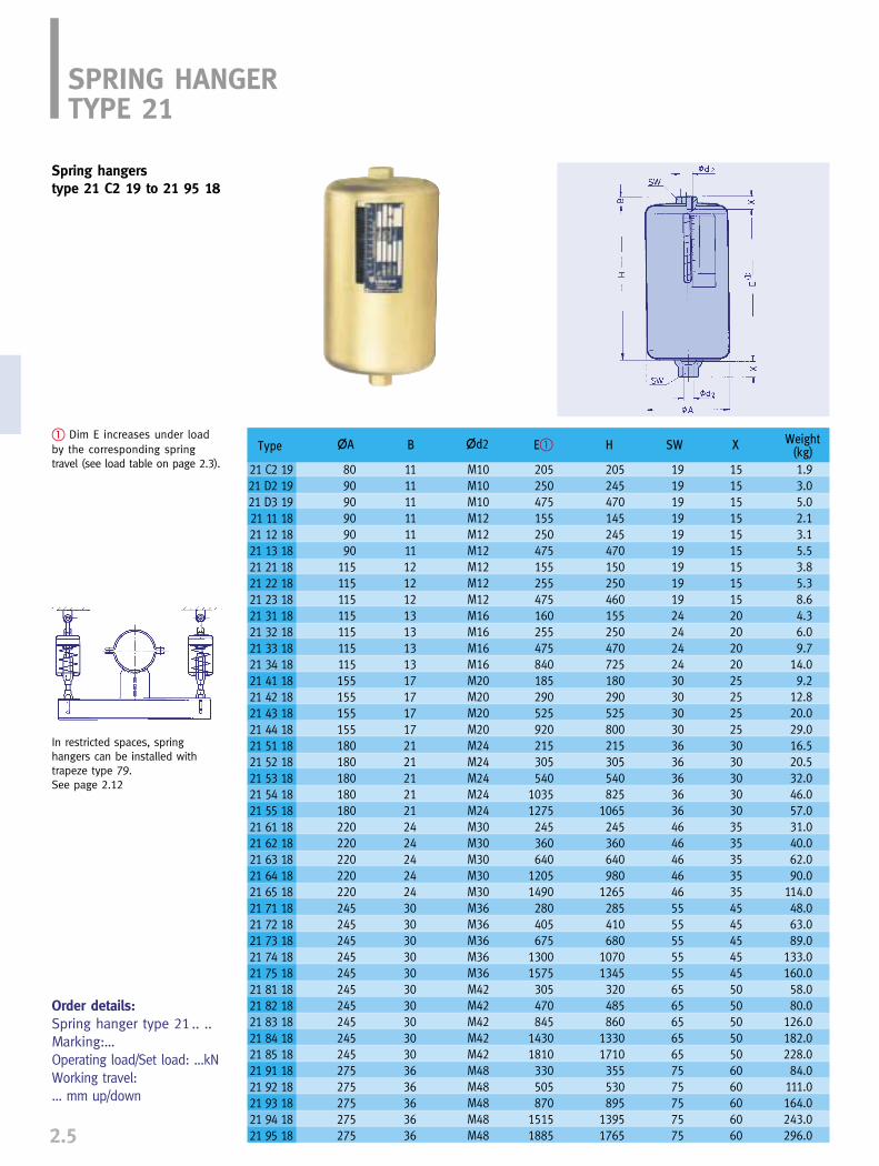
2.5
SPRING HANGERTYPE 21
Spring hangers type 21 C2 19 to 21 95 18
� Dim E increases under loadby the corresponding spring travel (see load table on page 2.3).
Order details:Spring hanger type 21 .. ..Marking:…Operating load/Set load: ...kNWorking travel: ... mm up/down
In restricted spaces, springhangers can be installed withtrapeze type 79. See page 2.12
Type
21 C2 1921 D2 1921 D3 1921 11 1821 12 1821 13 1821 21 1821 22 1821 23 1821 31 1821 32 1821 33 1821 34 1821 41 1821 42 1821 43 1821 44 1821 51 1821 52 1821 53 1821 54 1821 55 1821 61 1821 62 1821 63 1821 64 1821 65 1821 71 1821 72 1821 73 1821 74 1821 75 1821 81 1821 82 1821 83 1821 84 1821 85 1821 91 1821 92 1821 93 1821 94 1821 95 18
�A B �d2 E� H SW X Weight(kg)
809090909090
115115115115115115115155155155155180180180180180220220220220220245245245245245245245245245245275275275275275
111111111111121212131313131717171721212121212424242424303030303030303030303636363636
M10M10M10M12M12M12M12M12M12M16M16M16M16M20M20M20M20M24M24M24M24M24M30M30M30M30M30M36M36M36M36M36M42M42M42M42M42M48M48M48M48M48
205250475155250475155255475160255475840185290525920215305540
10351275245360640
12051490280405675
13001575305470845
14301810330505870
15151885
205245470145245470150250460155250470725180290525800215305540825
1065245360640980
1265285410680
10701345320485860
13301710355530895
13951765
191919191919191919242424243030303036363636364646464646555555555565656565657575757575
151515151515151515202020202525252530303030303535353535454545454550505050506060606060
1.93.05.02.13.15.53.85.38.64.36.09.7
14.09.2
12.820.029.016.520.532.046.057.031.040.062.090.0
114.048.063.089.0
133.0160.058.080.0
126.0182.0228.084.0
111.0164.0243.0296.0

Type
22 11 1922 12 1922 13 1922 21 1922 22 1922 23 1922 31 1922 32 1922 33 1922 41 1922 42 1922 43 1922 51 1922 52 1922 53 19
�A B �d2C �d3 E � H R S SW1 SW2 XWeight
(kg)
525525525545545545590590590625625625645645645
808080959595959595
115115115140140140
606060707070757575808080909090
626262727272727272828282929292
909090
105105105105105105120120120135135135
303030303030303030353535353535
858585959595
100100100105105105115115115
464646464646464646555555656565
656565757575808080858585959595
240270340285320410360405510455515625550655865
440560840475595875490610890555685955630800
1175
350470750370490770385505785430560830480650
1025
M56x4M56x4M56x4M64x4M64x4M64x4M68x4M68x4M68x4M72x4M72x4M72x4M80x4M80x4M80x4
� Dim E increases under load bythe corresponding spring travel(see load table on page 2.4).
2
2.6
SPRING HANGERTYPE 22
Order details:Spring hanger type 22 .. ..Marking: …Operating load/Set load: …kNWorking travel: … mm up/down
Spring hangers type 22 11 19 to 22 53 19
blocking device
Spring hanger type 22with weld-on clevis mounted.
Spring hanger type 22with clevis mounted.
� Application in practice

Type
25 D2 1925 D3 1925 11 1825 12 1825 13 1825 21 1825 22 1825 23 1825 31 1825 32 1825 33 1825 41 1825 42 1825 43 1825 51 1825 52 1825 53 1825 61 1825 62 1825 63 1825 71 1825 72 1825 73 1825 81 1825 82 1825 83 1825 91 1825 92 1825 93 18
�A B�
9090909090
115115115115115115155155155180180180220220220245245245245245245275275275
350675200350675205355665210355675230395730265405740300465845350530900385605
1075415645
1110
M10M10M12M12M12M12M12M12M16M16M16M20M20M20M24M24M24M30M30M30M36M36M36M42M42M42M48M48M48
1313131313131313181818252525282828343434404040474747545454
245470145245470150250460155250470180290525215305540245360640300430700335500875370545910
380705230380705235385695250395715280445780325465800375540920440620990495715
1185535765
1230
2.84.92.13.15.53.55.18.43.75.38.98.0
11.518.614.518.029.026.035.056.040.053.079.044.066.0
111.067.092.0
143.0
�d2 �d4 H X max� Weight(kg)
Type B C d6 E
72 D9 28 125 95 12 872 19 28 125 95 12 872 29 28 150 115 14 1072 39 28 150 115 14 1272 49 28 190 140 18 1272 59 28 220 170 18 1272 69 28 260 200 23 1572 79 28 290 215 23 2072 89 28 290 215 27 2072 99 28 340 255 33 25
Load group
Order details:Spring hanger type 25 .. ..Marking: ..Operating load/Set load: …kNWorking travel: … mm up/down
2.7
SPRING HANGER TYPE 25
Spring hangers (seated)type 25 D2 19 to 25 93 18
� Dims B and X reduce under loadby the corresponding spring travel (see load table on page 2.3)
For special applications spring hangers type25 can be manufactured as trapeze units.
Base plateType 72 can be added totype 25 on request.

Type
26 11 1926 12 1926 13 1926 21 1926 22 1926 23 1926 31 1926 32 1926 33 1926 41 1926 42 1926 43 1926 51 1926 52 1926 53 19
�A
510510510560560560610610610610610610610610610
395565945405575955420590970470650
1025530750
1220
345465745355475755370490770420550825480650
1020
606060707070707070808080909090
464646464646464646555555656565
205235310265300390345390490395450555465545725
M56x4M56x4M56x4M64x4M64x4M64x4M68x4M68x4M68x4M72x4M72x4M72x4M80x4M80x4M80x4
530700
1080560730
1110585755
1135645825
1200725945
1415
B� �d2 X max��d4 HWeight
(kg)SW
2
2.8
� Dims B and X reduce underload by the corresponding springtravel (see load table on page2.4)
Order details:Spring hanger type 26 .. ..Marking: ..Operating load/Set load: …kNWorking travel: … mm up/down
SPRING HANGERTYPE 26
Spring hanger (seated)type 26 11 19 to 26 53 19
blocking device
Special spring assemblies for boiler support.

Type
29 C2 1929 D1 1929 D2 1929 D3 1929 11 1829 12 1829 13 1829 21 1829 22 1829 23 1829 31 1829 32 1829 33 1829 41 1829 42 1829 43 1829 51 1829 52 1829 53 1829 61 1829 62 1829 63 1829 71 1829 72 1829 73 1829 81 1829 82 1829 83 1829 91 1829 92 1829 93 18
�A �B
80909090909090115115115115115115155155155180180180220220220245245245245245245275275275
105125125125125125125150150150150150150190190190220220220260260260290290290290290290340340340
75959595959595
115115115115115115140140140170170170200200200215215215215215215255255255
10121212121212141414141414181818181818232323232323272727333333
36363636363636363636363636484848505050505050525252555555606060
210145245470145245470150250460155250470180290525210300535245360640300425695335500870370545910
80808080808080
100100100100100100120120120150150150170170170200200200200200200240240240
6888888
101010121212121212121212151515202020202020252525
270195305550195305550200310540205310550240360615270370625305430730360500790400575965440625
1010
2.63.24.36.63.44.67.25.67.6
11.16.38.4
13.011.916.025.020.024.337.034.044.068.053.068.097.060.084.0
133.091.0
118.0173.0
d6 FE� Weight(kg)�D�C H S
Type Load group øL1
70 19 16 C, D, 1 4070 39 16 2, 3 4070 49 16 4 6570 59 16 5 6570 69 16 6 11070 79 16 7 11070 89 16 8 15070 99 16 9 150
2.9
SPRING SUPPORTTYPE 29
Spring supportstype 29 C2 19 to 29 93 18
PTFE (Teflon) slide platesare recommended for con-siderable horizontal load displacements.
� Dim E is independent of the load setting. It variesunder load by the corresponding spring travel (see loadtable page 2.3). Adjustment possibility +30mm.
Order details: Spring support type 29 .. ..Marking: ..Operating load/Set load: …kNWorking travel: … mm up/down
øL1
Suitable extensions can beordered to bridge greaterinstallation heights.
Type 29 .9 15 - E…Load group
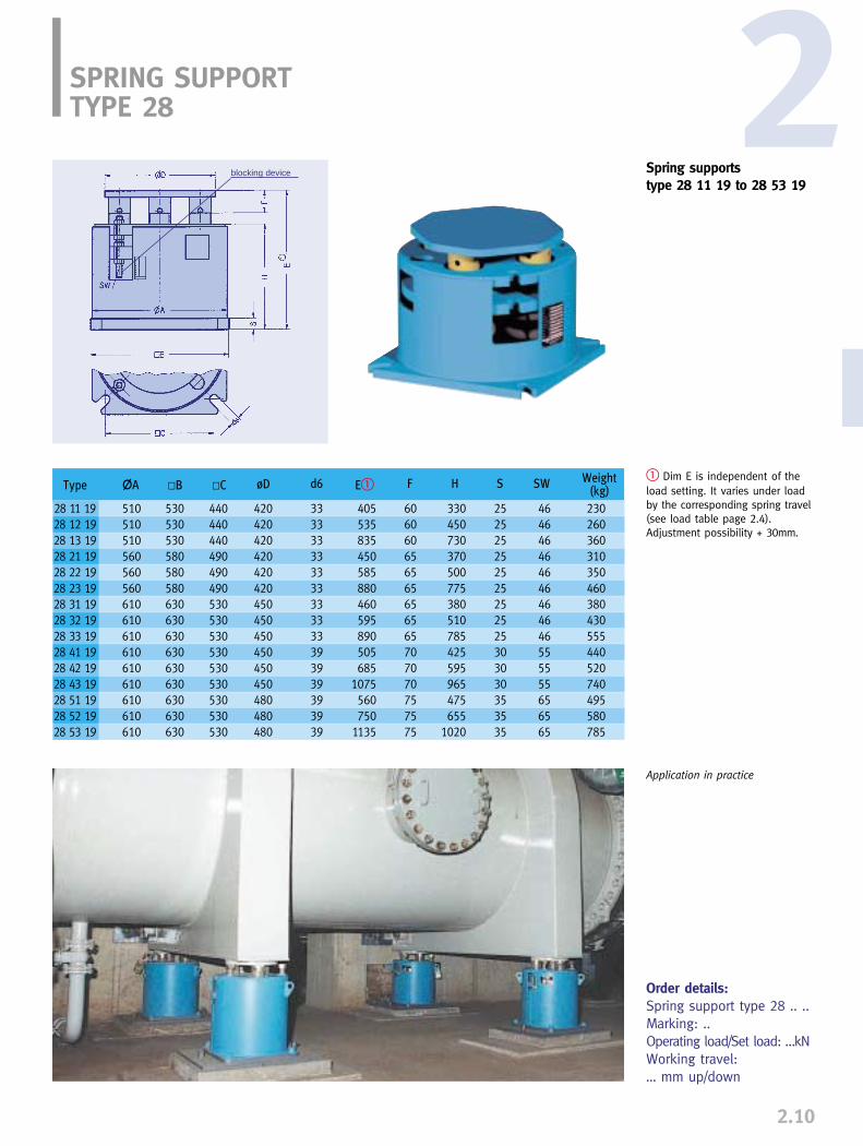
Type
28 11 1928 12 1928 13 1928 21 1928 22 1928 23 1928 31 1928 32 1928 33 1928 41 1928 42 1928 43 1928 51 1928 52 1928 53 19
�A
510510510560560560610610610610610610610610610
530530530580580580630630630630630630630630630
440440440490490490530530530530530530530530530
420420420420420420450450450450450450480480480
405535835450585880460595890505685
1075560750
1135
330450730370500775380510785425595965475655
1020
230260360310350460380430555440520740495580785
333333333333333333393939393939
606060656565656565707070757575
252525252525252525303030353535
464646464646464646555555656565
�B øD FE� Weight(kg)
SW�C H Sd6
2SPRING SUPPORTTYPE 28
Spring supportstype 28 11 19 to 28 53 19
� Dim E is independent of theload setting. It varies under loadby the corresponding spring travel(see load table page 2.4).Adjustment possibility + 30mm.
Order details:Spring support type 28 .. ..Marking: ..Operating load/Set load: …kNWorking travel: … mm up/down
2.10
blocking device
Application in practice
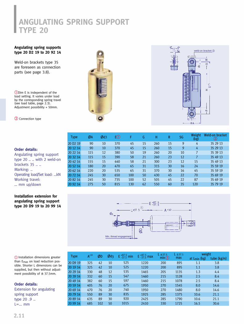
ANGULATING SPRING SUPPORTTYPE 20
Angulating spring supportstype 20 D2 19 to 20 92 14
Weld-on brackets type 35are foreseen as connectionparts (see page 3.8).
�Dim E is independent of theload setting. It varies under loadby the corresponding spring travel (see load table, page 2.3).Adjustment possibility + 50mm.
� Connection type
Order details:Angulating spring supporttype 20 .. .. with 2 weld-onbrackets 35 .. ..Marking: ..Operating load/Set load: …kNWorking travel: … mm up/down
2.11
� Installation dimensions greaterthan Emax on load reduction pos-sible. Shorter L dimensions can besupplied, but then without adjust-ment possibility of � 37.5mm.
Order details:Extension for angulatingspring supporttype 20 .9 ..L=... mm
Installation extension for angulating spring supporttype 20 D9 19 to 20 99 14
weld-on bracket �
Min. thread engagement
�
Type
20 D2 1920 12 1420 22 1420 32 1420 42 1420 52 1420 62 1420 72 1420 82 1420 92 14
�A
9090
115115155180220245245275
10101215152020303050
370370380390440470535650735815
45455058586565
100100130
15151921213131505262
260260260260300315370430505550
4477
1524457087
120
35 29 1335 29 1335 39 1335 49 1335 49 1335 59 1935 59 1935 69 1935 69 1935 79 19
15152023233030454560
99
1012121616222235
�d3 H R SGFWeld-on bracket
�Weight
(kg)E�
Type
20 D9 1920 19 1420 29 1420 39 1420 49 1420 59 1420 69 1420 79 1420 89 1420 99 14
A+50
325325330332382405470550635685
424248606076768989102
10101215152020303050
525525535547597675740835920
1015
1220122014651460146019501950192524252410
200200205215215270270285285330
895895
11351128107815451480137517901725
1.11.11.32.52.58.08.0
10.610.616.5
3.83.84.48.48.4
14.614.621.121.130.6
�DL �37.5
min at Lmin (kg)E +87.5 min-37.5�d3
L �37.5max� tube (kg/m)
G
weightE +87.5 max-37.5

2
2.12
SPRING HANGER TRAPEZESTYPE 79
� The 4th digit of the type desig-nation denotes the travel rangeof the spring hanger.1=50mm, 2=100mm, 3=200mm
�Permissible center load of theother load conditions see table3.5.3 page 0.5 (Nominal load 120 kN see load group 9)
�Dim E increases under load bythe corresponding spring travel(see load table on page 2.3)
�The maximum L dimensionsmay be increased to 2400mm,with load reduction of 5% foreach 100mm of extension.
Order details:Trapeze type 79 .. 11L= … mm
ø
Order details:Trapeze, type 79 .. 19 L= … mm
�
�
TrapezeType
79 D.� 1179 1. 1179 2. 1179 3. 1179 4. 1179 5. 1179 6. 1179 7. 1179 8. 1179 9. 11
�d2 L max
Weight (kg) L= 1000mm at travel rangeNominal load
(kN)�
1.252.55
10204080
120160200
M10M12M12M16M20M24M30M36M42M48
1400140016001600175021002100210021502200
B
80100100100120160200240260280
-1926274168
110159186243
162129304876
128189230297
202635386399
172241322403
1.11.62.02.02.74.36.18.39.3
10.3
�per 100mm
(kg)1 2 3
E dimensionapprox. �
travelrange �
123
3055
105
Notes �...� see above
Spring Hanger trapezestype 79 .. 11
For restricted spaces thedesign shown can bemanufactured as a special.
-50
TrapezeType
79 D.� 1979 1. 1979 2. 1979 3. 1979 3. 1979 4. 1979 4. 1979 5. 1979 5. 1979 6. 1979 6. 1979 7. 1979 7. 1979 8. 1979 8. 1979 9. 19
�d2 L maxNominal load
(kN)�
��
E� at Travel range
1 2 3 U A B X
1.252.5
51010202040408080
120120160160200
M10M12M12M16M16M20M20M24M24M30M30M36M36M42M42M48
170017001700900
180014001800125018001250240018002400120018001800
–290290315300345345405390445435505500560555610
385385390410395450450495480560550630625725720785
610610610630615685685730715840830900895
110010951150
80808080
120120140140180200260260300260300300
9090
115115115155155180180220220245245245245275
140140140140190190200200230250310310350310350350
15151520202525303035354545505060
Weight (kg) L= 1000 at travel range
-2428294153617793
138174214245242273335
2626313245606885
101156192244275286317390
30313739527482
108124200236296327378410495
1.71.71.71.72.72.73.23.24.45.17.67.69.27.69.29.2
�per 100 mm1 2 3
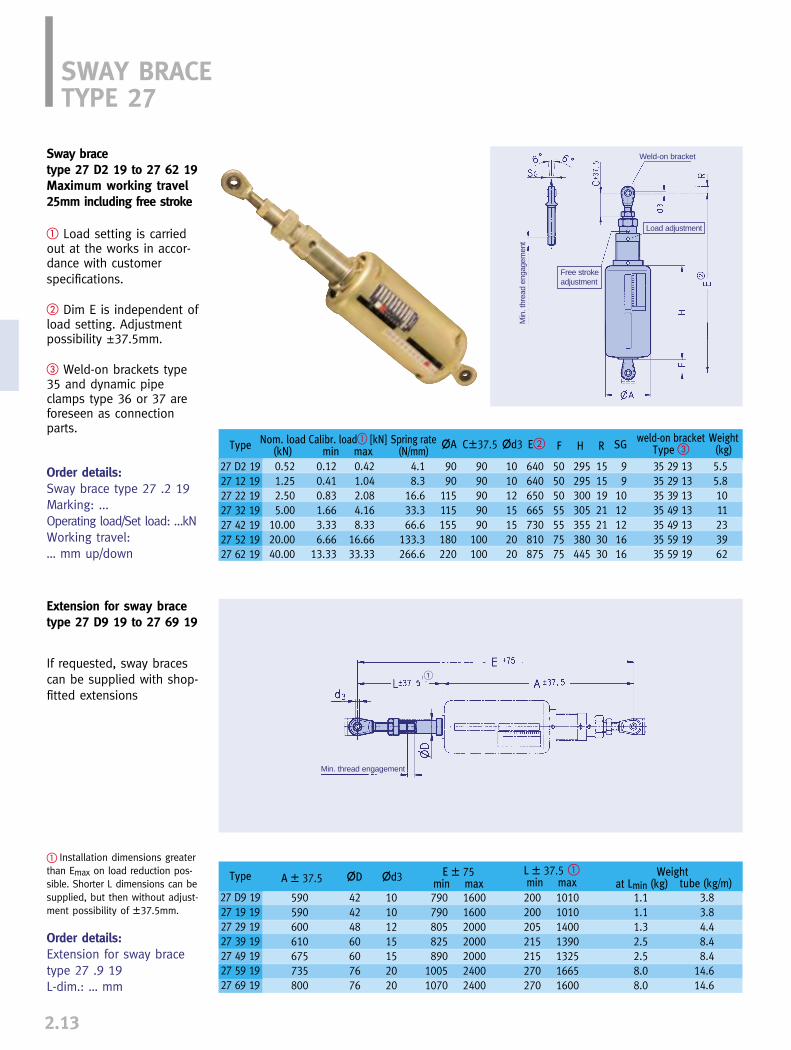
SWAY BRACETYPE 27
Sway bracetype 27 D2 19 to 27 62 19Maximum working travel25mm including free stroke
� Load setting is carriedout at the works in accor-dance with customer specifications.
� Dim E is independent ofload setting. Adjustmentpossibility �37.5mm.
� Weld-on brackets type35 and dynamic pipeclamps type 36 or 37 areforeseen as connectionparts.
Order details:Sway brace type 27 .2 19Marking: ...Operating load/Set load: …kNWorking travel: … mm up/down
If requested, sway bracescan be supplied with shop-fitted extensions
2.13
Extension for sway bracetype 27 D9 19 to 27 69 19
� Installation dimensions greaterthan Emax on load reduction pos-sible. Shorter L dimensions can besupplied, but then without adjust-ment possibility of �37.5mm.
Order details:Extension for sway bracetype 27 .9 19L-dim.: … mm
Min. thread engagement
Min
. thr
ead
enga
gem
ent
Weld-on bracket
Load adjustment
Free stroke adjustment
�
Type
27 D2 1927 12 1927 22 1927 32 1927 42 1927 52 1927 62 19
�A �d3 SGFweld-on bracket
Type �Nom. load
(kN)
0.521.252.505.00
10.0020.0040.00
4.18.3
16.633.366.6
133.3266.6
9090
115115155180220
9090909090
100100
10101215152020
640640650665730810875
50505055557575
295295300305355380445
15151921213030
99
1012121616
5.55.81011233962
0.12 0.420.41 1.040.83 2.081.66 4.163.33 8.336.66 16.66
13.33 33.33
35 29 1335 29 1335 39 1335 49 1335 49 1335 59 1935 59 19
E�Calibr. load� [kN]min max
Spring rate(N/mm)
C�37.5 H RWeight
(kg)
Type
27 D9 1927 19 1927 29 1927 39 1927 49 1927 59 1927 69 19
�D �d3 E � 75min maxA � 37.5
590590600610675735800
42424860607676
10101215152020
790 1600790 1600805 2000825 2000890 2000
1005 24001070 2400
200 1010200 1010205 1400215 1390215 1325270 1665270 1600
1.11.11.32.52.58.08.0
3.83.84.48.48.4
14.614.6
at Lmin (kg)L � 37.5 �min max tube (kg/m)
Weight

2
2.14
� upper articulated joint� counter nut� counter nut� guide tube� threaded tube� counter nut� guide rod name plate with travel
scale travel scale� lower ball bushing joint
�
�
�
�
�
�
�
�
Load and installation length areadjustable to the correspondingspecifications.
Transfer of force on alternatingdirection of force.
compressive force tensile forceneutral position
Function diagram

INSTALLATION ANDOPERATING INSTRUCTIONS
Spring hanger, type 21 (blocked)
Spring hanger, type 25 (blocked)
Spring hangers and spring supportstypes 20, 21, 22, 25, 26, 27, 28, 29
1. Transport and storageWhen transporting, threaded connectionsand travel stops must not be damaged.When stored in the open they should beprotected from dirt and moisture.
2. Delivery conditionUnless agreed otherwise, spring hangers andspring supports are delivered to the siteblocked in the installation position.When hangers or supports are blocked (travelstop in both directions), the spring plate islocked by a special blocking device in thehousing slots.
All spring hangers and supports are suppliedwith a riveted aluminum name plate fittedwith an integral travel scale.The following information is stamped on thename plate:
➜ order number if required➜ set load ➜ theoretical travel➜ spring rate of the hanger or support➜ marking and position number➜ test stamp if required
The serial number is stamped directly on the housing.
Spring support, type 29 (blocked)
2.15
Blocking device for singlespring models
Name plate for spring hanger
Spring hangers and sup-ports are used to compen-sate for the thermal move-ment to be expected inpiping systems. Fortrouble-free functioning,correct installation isessential, observing thefollowing instructions:
If specially ordered, the stops can be bolted securely tothe hanger or support after deblocking.
Securing clamp Fixing bolt
The blocking units for single spring models consist ofa set of hinged metal plates. Individual plates can beswivelled into any desired blocking position.
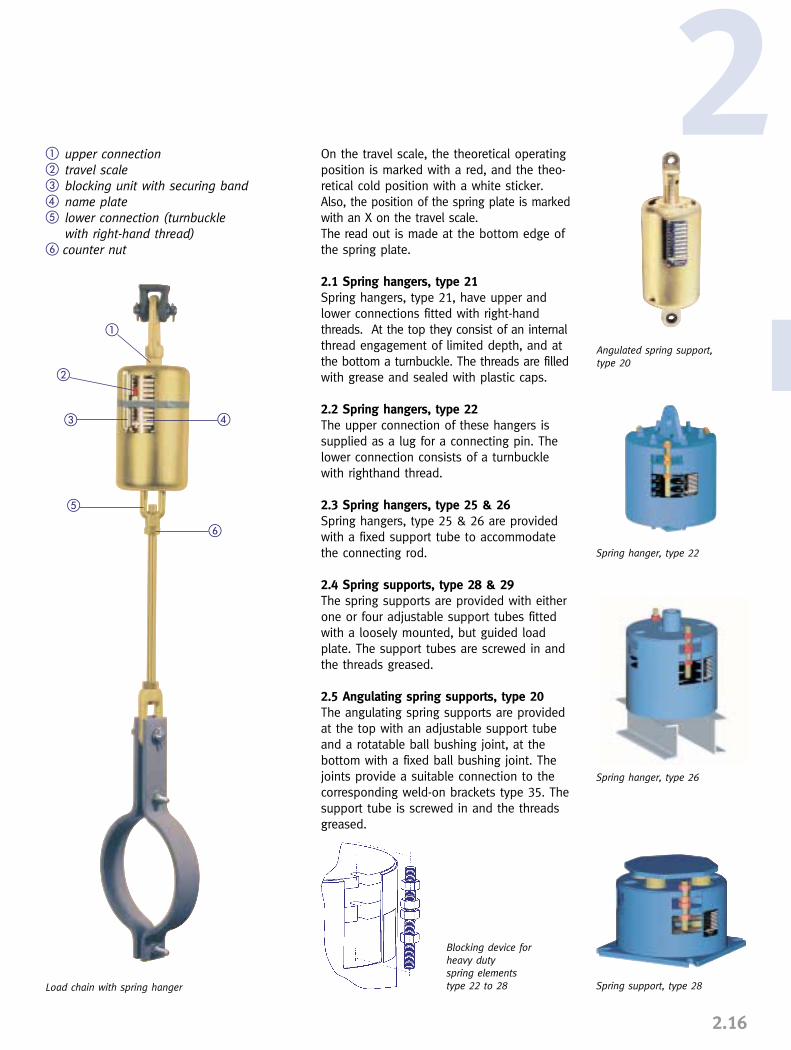
� upper connection� travel scale� blocking unit with securing band� name plate� lower connection (turnbuckle
with right-hand thread)� counter nut
On the travel scale, the theoretical operatingposition is marked with a red, and the theo-retical cold position with a white sticker.Also, the position of the spring plate is markedwith an X on the travel scale. The read out is made at the bottom edge ofthe spring plate.
2.1 Spring hangers, type 21Spring hangers, type 21, have upper andlower connections fitted with right-handthreads. At the top they consist of an internalthread engagement of limited depth, and atthe bottom a turnbuckle. The threads are filledwith grease and sealed with plastic caps.
2.2 Spring hangers, type 22The upper connection of these hangers issupplied as a lug for a connecting pin. Thelower connection consists of a turnbucklewith righthand thread.
2.3 Spring hangers, type 25 & 26Spring hangers, type 25 & 26 are providedwith a fixed support tube to accommodatethe connecting rod.
2.4 Spring supports, type 28 & 29The spring supports are provided with eitherone or four adjustable support tubes fittedwith a loosely mounted, but guided loadplate. The support tubes are screwed in andthe threads greased.
2.5 Angulating spring supports, type 20The angulating spring supports are providedat the top with an adjustable support tubeand a rotatable ball bushing joint, at thebottom with a fixed ball bushing joint. Thejoints provide a suitable connection to thecorresponding weld-on brackets type 35. Thesupport tube is screwed in and the threadsgreased.
�
�
��
�
�
Load chain with spring hanger
2
2.16
Blocking device forheavy dutyspring elementstype 22 to 28
Angulated spring support, type 20
Spring hanger, type 26
Spring hanger, type 22
Spring support, type 28

2.6 Sway braces, type 27Sway braces are provided at the top with alength-adjustable ball bushing joint and atthe bottom with a fixed lug suitable for con-nection to weld-on bracket type 35 or dyna-mic clamp type 36 or 37. Presetting of theload and if necessary the free stroke arecarried out at the works in accordance withcustomer requirements.
3. InstallationWhen installing, the rules given in InstallationInstructions for Piping must also be observed.Special care must also be given to theinstalled position of the connecting rodsover the whole support chain. Two possibili-ties are the norm:
1. The connecting rods are to be installed atan angle corresponding to the horizontal dis-placement to be expected. A vertical positionof the rods is expected under normal opera-ting conditions.
2. The connecting rods are to be installedvertically for easier checking. A controlledangled position under normal operating con-ditions is thereby permitted.
In each case there should be unified rulesand regulations for the whole plant.
Connecting rods and points must be actuatedby load at connection points.
3.1 Spring hangers, type 21Connection is made by screwing the connec-ting rod into the upper threaded connectionhole in type 21, and by screwing the lowerconnecting rod into the turnbuckle. As a tension range and length adjustment,the turnbuckle length available in the hangercan be used for the connecting rod.
3.2 Spring hanger, type 22Connection is made by pinning the lug to theupper attachment point and by screwing thelower connecting rod into the turnbuckle. As a tension range and length adjustment,the turnbuckle length available in the hangercan be used for the connecting rod.
2.17
3.3 Spring hangers, type 25 & 26These spring hangers are set on beams andcorrespondingly positioned. Once the preciseposition is defined the unit should be securedagainst horizontal movement. The load actu-ated connection is made via the connectingrod, which is led throught the support tubeand tightened with a nut.
3.4 Spring supports, type 28 & 29After positioning, these spring supports areconnected to the structure by bolting or wel-ding the base plate to the structure. Loaddistribution is applied through the loadplate or through one or more adjustableload tubes.
3.5 Angulating spring supports, type 20The angulating spring supports are connec-ted to the structure after correspondingpositioning by welding the lower weld-onbracket. Load distribution is applied throughthe upper weld-on bracket via the pinconnection to the height-adjustable loadtube.
3.6 Sway braces, type 27After positioning of the connection points,the weld-on brackets are attached andconnection is made through the connectionpins of the brackets or dynamic clamps. Theball bushing joints allow a � 37.5mmadjustment of installation length.
4. Removing the travel stopsThe spring hangers and supports should onlybe deblocked when the set load is fullyapplied to all the supports, which form onesystem. If this is the case, the travel stopscan easily be removed. If the travel stops arejammed, the load actually applied does notcorrespond with the theoretical adjustedload. (See Installation and OperatingInstructions, Constant Hangers, page 1.23,item 4, in this regard).
Sway brace, type 27
Case 1Attachment rods vertical duringplant operation
Case 2Attachment rods vertical in installation condition
cold position
cold position
hot position
hot position

��
��
��
2
2.18
� connecting rod� counter nut� lock nut� load tube� travel stop� travel scale� name plate
Example of an arrangement with type 25
5. Load readjustment
5.1 Spring hangers, spring supportsFor spring hangers the load can be readjustedby loosening or tightening the threaded rodsat the lock nut. For spring supports, the loadcan be readjusted by a corresponding adjust-ment of the load tube.Under all circumstances, however, the approp-riate technical department must be consultedbefore attempting any load readjustment.
5.2 Sway braces, type 27Load readjustment is made by rotating thethreaded tube (A). The large counter ring (B)is loosened to do this. In order to maintainthe E dimension, the resulting gap is com-pensated for by readjustment of the guidetube.
For sway braces, a free stroke can be set.To do this, the guide tube (C) opposite theinner guide rod (D) is to be unscrewed (loosen middle lock nut). The working travelreduces in the compression direction inaccordance with the free stroke selected.
6. CommissioningBefore commissioning it must be checkedthat each hanger or support allows the pre-calculated movement of the piping.The working travel of the hanger or supportcan be read off at the bottom edge of thespring plate as travel in the blocking slots,and read directly off the travel scale.
7. Checking and maintenanceThe correct functioning of the spring hangersor supports can be checked in all operatingsituations by noting the position of thespring plates. Under normal operating conditions no main-tenance is required.
�
Spring hanger type 22 with eyenuts as transport lugs
Hydraulic
cylinder
Hydraulic
cylinder
Hydraulic cylinder
Installation devices for readjust-ment of the set load for types22, 26 and 28. The devices canequally well be used asdeblocking aids.
�C�D
�A�B
SHOCK ABSORBERS, ENERGY ABSORBERS, RIGID STRUTS
PRODUCT GROUP
3


0
1
2
4
5
6
7
8
9
0
1
2
4
5
6
7
8
93.0
SHOCK ABSORBERS, ENERGY ABSORBERS (E-BARS),RIGID STRUTS, DYNAMIC PIPE CLAMPS
Field of application________________________________________________3.1
Main products ____________________________________________________3.2
Recommendations for use__________________________________________3.3
Shock absorbers, type 30, type 31 __________________________________3.4
Installation extensions, type 33 _____________________________________3.7
Weld-on brackets, type 35__________________________________________3.8
Operational performance, type 30, type 31____________________________3.9
Permissible stress factors, type 30, type 31__________________________3.10
Mode of operation, type 30, type 31________________________________3.11
Shock absorbers, design characteristics _____________________________3.13
Shock absorbers, function tests ____________________________________3.14
Installation instructions, type 30, type 31____________________________3.15
Maintenance recommendations type 30, type 31 _____________________3.17
Dynamic pipe clamps, type 36, type 37 _____________________________3.19
Dynamic pipe clamps overview, OD 33.7 - OD 914.4 __________________3.21
Dynamic pipe clamps, installation instructions________________________3.31
Energy absorbers (E-Bar), type 32 __________________________________3.33
Rigid struts, type 39______________________________________________3.37
Pipe whip restraints ______________________________________________3.41
CONTENTS PAGE
3
PRODUCTGROUP 3

Product group 3 componentsPipe supports specially designed for thepurpose are necessary to absorb and trans-fer loads from dynamic events. With ProductGroup 3, LISEGA provides a comprehensivesystem whereby all fields of application arecovered by the corresponding ideal compo-nent. This enables users to exploit optimumconcepts.
The LISEGA Product Group 3 includes thefollowing main products:
➜ shock absorbers, types 30 and 31➜ energy absorbers (E-Bars), type 32➜ rigid struts, type 39
A comprehensive selection of connection pos-sibilities is available for the correct installa-tion of the main products:
➜ installation extensions, type 33➜ weld-on brackets, type 35➜ dynamic pipe clamps, types 36 and 37
In accordance with the LISEGA modularsystem, the connecting parts are designedto be compatible and are subject to uniformcalculation criteria. A generally applicabletable of permissible loads can be found onpage 0.5 of the Technical Specifications.
The fundamental calculation procedurescomply with international regulations andstandards and are certified by practical typeand suitability tests. Design Report Summaries in accordancewith ASME III NF are available.
Dynamic eventsWhenever unplanned dynamic events occur,LISEGA Product Group 3 supports have thejob of protecting the piping or other com-ponents affected from any damage.
Undesirable abrupt movement of the com-ponents in the system can be caused by:
A Internal excitation, such as:
➜ pressure shocks from valve operation➜ water hammer➜ boiler events➜ pipe breakage
B External excitation, such as:
➜ wind load➜ seismic events➜ aircraft impact➜ explosions
Components affected can be:
➜ piping➜ pumps➜ valve assemblies➜ pressure vessels➜ steam generators
To avoid unacceptable ten-sion and moments in thepiping system, unplanneddisplacement in piping orother plant components mustbe eliminated. However, ther-mal movement must not behindered in any way!
PRODUCT GROUP 3FIELD OF APPLICATION
3.1
Diagram of an operating basis earthquake (O.B.E.)
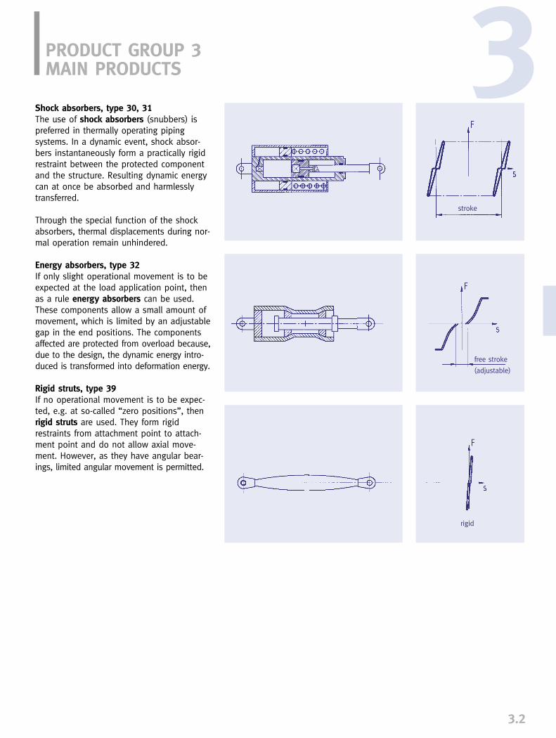
3.2
3Shock absorbers, type 30, 31The use of shock absorbers (snubbers) ispreferred in thermally operating pipingsystems. In a dynamic event, shock absor-bers instantaneously form a practically rigidrestraint between the protected componentand the structure. Resulting dynamic energycan at once be absorbed and harmlesslytransferred.
Through the special function of the shockabsorbers, thermal displacements during nor-mal operation remain unhindered.
Energy absorbers, type 32If only slight operational movement is to beexpected at the load application point, thenas a rule energy absorbers can be used.These components allow a small amount ofmovement, which is limited by an adjustablegap in the end positions. The componentsaffected are protected from overload because,due to the design, the dynamic energy intro-duced is transformed into deformation energy.
Rigid struts, type 39If no operational movement is to be expec-ted, e.g. at so-called “zero positions”, thenrigid struts are used. They form rigidrestraints from attachment point to attach-ment point and do not allow axial move-ment. However, as they have angular bear-ings, limited angular movement is permitted.
PRODUCT GROUP 3MAIN PRODUCTS
stroke
free stroke
(adjustable)
rigid

3.3
PRODUCT GROUP 3RECOMMENDATIONS FOR USE
Product Group 3 components are dynamicallystressed. In their use, the following pointsmust be observed for effective functioning:
1. Where the design of dynamically fixedpoints is concerned, the stiffness of the supporting system as a whole, i.e. of allcomponents in the support chain, must beconsidered.
2. In the selection of unit sizes, the total ofall loadings avising must be taken intoaccount.
3. For given loads it must be made clear,beyond any doubt, which level of design load(H, HZ, HS, and/or Level A,B,C,D) the datacorresponds to. The table of permissible loadson page 0.5 of the Technical Specificationsmust be observed.
4. The stroke length of shock absorbersshould not be fully exploited. An overtravelsafety margin of 10mm at each end of thesnubber should be maintained.
5. When arranging the components, sufficientlateral freedom should be allowed so thatthere is no jamming at connection lugs.
6. When shock absorbers are arranged inparallel, it is recommended that load re-serves be considered. Instead of 50%, ineach case it is recommended that bothshock absorbers be designed to take 70%of the total calculation load.
7. The installation drawings should clearlyindicate how much freedom of angulationmay be required by the components.
8. Any necessary torque values for threadedconnections in the structural attachmentsshould be indicated.
9. Before commissioning the plant, all sup-port points should again be visually inspec-ted.
10. The LISEGA instructions for commissioningand inspection, as well as the maintenancerecommendations, are to be observed.
� Special design of dynamic restraint clamp
Type 37
Type 30
Type 33
Type 35
Type 35
Type 39
Type 36
Type 35
Type 39
Type 36 Type 30
Type 35
Type 39
Type 37 Type 39
Type 35
Type 30
Type 35
Type 35
Type 30
Type 36
Type 36
Type 35
Type 33
Type 30Type 39
Type 35
Type 39
Type 35

3.4
LISEGA shock absorbers have stood the testof time in practical applications for overthree decades, and thereby proven theiroutstanding reliability. Extensive operationalexperience has, through constant furtherdevelopment, led to a matured product, uni-versally respected and leading worldwide.
Access to shock absorbers after installation isgenerally difficult and, because of possibledanger from radiation when installed innuclear power plants, involves stringentsafety regulations for personnel. The highestdemands are therefore made on reliable andmaintenance-free continuous service.
For the reliable operational safety of shockabsorbers, the quality of the following criticalcomponents, together with the functional prin-ciple and whole design, is a decisive factor:
➜ sealing systems➜ piston and rod guides➜ hydraulic fluid➜ sliding surfaces➜ corrosion-resistant interiors➜ control valve system
SHOCK ABSORBERSTYPE 30, 31
The most frequent causes of failure in shock absor-bers are prematurewear and tear andcorrosion. For this reason LISEGA shock absorbersare manufacuredfrom non-corroding materials and any form of metal to metal contactis precluded by the use of special guide bands.
At LISEGA, the sealing system, guidings andhydraulic fluid are certified through reliablequalification procedures to give at least 23years trouble free operation in nuclear powerstations under normal operating conditions.
The following qualities have led to the recog-nized superiority of LISEGA shock absorbers:
➜ non-corroding materials➜ special sealing systems➜ vibration proof guide systems➜ pressurized self-contained hydraulic system➜ dynamic function➜ exchangeable control valves (Type 31)➜ 23 years approved maintenance-free
operation➜ 40 year lifespan➜ certified by ASME - NCA 3800
➜ certified by TÜV qualification testing
3

SHOCK ABSORBERSTYPE 30
3.5
� See Technical Specifications, table “Permissibleloads” on page 0.5 and “Welding the weld-on brackets” on page 3.16
� Usual design load for earthquakes and similar loadevents. See also Technical Specifications, page 0.5
� Emin = piston rod retractedEmax = piston rod extended
To bridge greater installed lengths,extensions, type 33 (page 3.7) can be used.
Order details:Shock absorber type 30 .. ..With two weld-on bracketstype 35 .. .., Marking:…
Type 30 18 16 to 30 03 12Series producedStandard design
Available from stock orfrom running production.Only non-corroding materi-als are used. Connectionlugs (material = P250GH,C45E+QT) attached viathreaded connections aregalvanized.
3.5
� When exchanging other products, the connection dimensions such as pin diameters and lug lengths canbe made to fit the attachments already built into thestructure.
�Units with longer strokes can be provided onrequest.
�
conn. lug
ball bush
name plate
piston rod cover
travel indicator
sight glass
Type
30 18 1630 38 1630 39 1630 42 1630 43 1630 52 1330 53 1330 62 1630 63 1630 72 1630 73 1630 82 1630 83 1630 92 1330 93 1330 02 1230 03 12
Nom. load(kN)�
Stroke�
�D �d3 E�min F� R SG
Weight(kg)
E�max
388
18184646
100100200200350350550550
10001000
EmergencyLevel C �
4.010.610.623.923.961.061.0141 141267267472472735735
13351335
100100200150300150300150300150300150300150300150300
5470708585
135135170170200200270270300300390390
101212151520203030505060607070
100100
2203154103955454455955356856157657308807609109351085
320415610545845595895685985765
1065880
1180910
121010851385
18505058586565
100100130130165165165165240240
15202022.522.53030454560607575105105145145
910101212161622223535444449497070
1.94.35.78.3
12.020.029.037.051.061.078.0
122.0147.0175.0207.0390.0460.0
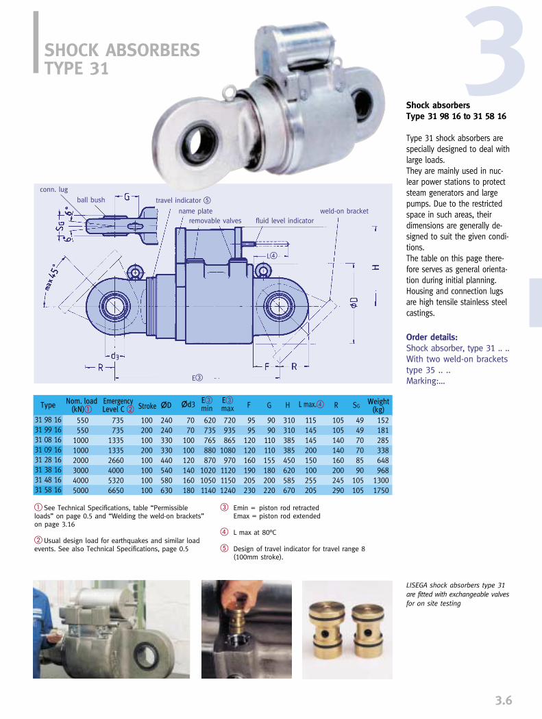
3.6
3Shock absorbersType 31 98 16 to 31 58 16
Type 31 shock absorbers arespecially designed to deal withlarge loads. They are mainly used in nuc-lear power stations to protectsteam generators and largepumps. Due to the restrictedspace in such areas, theirdimensions are generally de-signed to suit the given condi-tions. The table on this page there-fore serves as general orienta-tion during initial planning.Housing and connection lugsare high tensile stainless steelcastings.
� See Technical Specifications, table “Permissibleloads” on page 0.5 and “Welding the weld-on brackets”on page 3.16
� Usual design load for earthquakes and similar loadevents. See also Technical Specifications, page 0.5
Order details:Shock absorber, type 31 .. ..With two weld-on bracketstype 35 .. ..Marking:…
SHOCK ABSORBERS TYPE 31
� Emin = piston rod retractedEmax = piston rod extended
� L max at 80°C
� Design of travel indicator for travel range 8(100mm stroke).
LISEGA shock absorbers type 31are fitted with exchangeable valvesfor on site testing
conn. lug
ball bush travel indicator �
name plateremovable valves fluid level indicator
weld-on bracket
Type
31 98 1631 99 1631 08 1631 09 1631 28 1631 38 1631 48 1631 58 16
Weight(kg)Stroke �D �d3 E�
min F G H R SGE�max L max.�Emergency
Level C �Nom. load
(kN)�
550550
100010002000300040005000
735735
133513352660400053206650
100200100200100100100100
240240330330440540580630
7070
100100120140160180
620735765880870
102010501140
720935865
1080970
112011501240
9595
120120160190205230
9090
110110155180200220
310310385385450620585670
115145145200150100255205
105105140140160200245290
494970708590
105105
152181285338648968
13001750
E�
L�

3.7
INSTALLATION EXTENSIONSTYPE 33
Installation extensions type 33 18 18 to 33 03 12
Type 33 extensions are usedto bridge larger installationlengths, thus avoiding struc-tural adjustments on site.
Connection to the shockabsorber or energy absorberis made at the cylinderbase. Standard threadedconnections allow the simple substitution of exten-sions for standard connec-tion lugs. The same appliesfor special connections,helpful when exchangingunits made by other manu-facturers, because this wayexisting structural con-nec-tions can remain (see page3.8).
Material:P355T1
Order details:Installation extensiontype 33 .. ..L= … mm for hydr. shock absorber
� Piston at midposition � Installation dimensions greater than E max on loadreduction possible. Shorter L dimensions can be supplied,but then without adjustment possibility.
min. thread engagement
extension tube
countering ring lug with ball bushing
Type
33 18 1833 38 1833 39 1833 42 1833 43 1833 52 1333 53 1333 62 1833 63 1833 72 1833 73 18
33 82 18
33 83 18
33 92 1333 93 1333 02 1233 03 12
+ per100mm
Nom. load(kN)
388
18184646
100100200200
350
350
550550
10001000
Shockabs.
strokeA� d3 D
maxE��max
L minE��min
L �37.5�min
L �37.5�max
205195195205205220220270270315315390
1071390886440440555555
520445230763395950600
144011151855135510701760885
14552200190018801555
100100200150300150300150300150300
150
300
150300150300
240315460412635455680510735560785
640
865
670895770995
1012121515202030305050
60
60
7070
100100
253030353548486464838390
10090
100115115160160
445510655617840675900780
1005875
110010301711125517511110133513251550
760760690
1175103014051280195018502415214017102400175023202870279526502550
0.450.600.600.900.901.501.502.302.305.005.00
10.0045.0010.0036.0033.0033.0090.0090.00
0.390.550.550.750.750.720.721.901.903.603.603.404.703.404.705.505.509.509.50
Weight (kg)
L�37.5
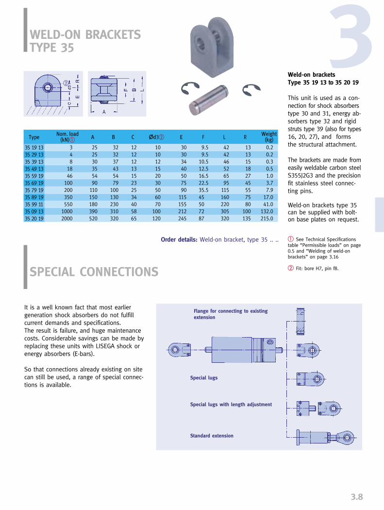
3.8
3WELD-ON BRACKETSTYPE 35
Weld-on bracketsType 35 19 13 to 35 20 19
This unit is used as a con-nection for shock absorberstype 30 and 31, energy ab-sorbers type 32 and rigidstruts type 39 (also for types16, 20, 27), and formsthe structural attachment.
The brackets are made fromeasily weldable carbon steelS355J2G3 and the precisionfit stainless steel connec-ting pins.
Weld-on brackets type 35can be supplied with bolt-on base plates on request.
� See Technical Specificationstable “Permissible loads” on page0.5 and “Welding of weld-onbrackets” on page 3.16
� Fit: bore H7, pin f8.
Order details: Weld-on bracket, type 35 .. ..
Flange for connecting to existingextension
Special lugs
Special lugs with length adjustment
Standard extension
It is a well known fact that most earliergeneration shock absorbers do not fulfillcurrent demands and specifications. The result is failure, and huge maintenancecosts. Considerable savings can be made byreplacing these units with LISEGA shock orenergy absorbers (E-bars).
So that connections already existing on sitecan still be used, a range of special connec-tions is available.
SPECIAL CONNECTIONS
�
Nom. load(kN)� A B C �d3� E F RL Weight
(kg)
348
1846
100200350550
10002000
Type
35 19 1335 29 1335 39 1335 49 1335 59 1935 69 1935 79 1935 89 1935 99 1135 09 1335 20 19
252530355490
110150180390520
323237435479
100130230310320
1212121315232534405865
101012152030506070
100120
30303440507590
115155212245
9.59.5
10.512.516.522.535.545507287
424246526595
115160220305320
131315182745557580
100135
0.20.20.30.51.03.77.9
17.041.0
132.0215.0
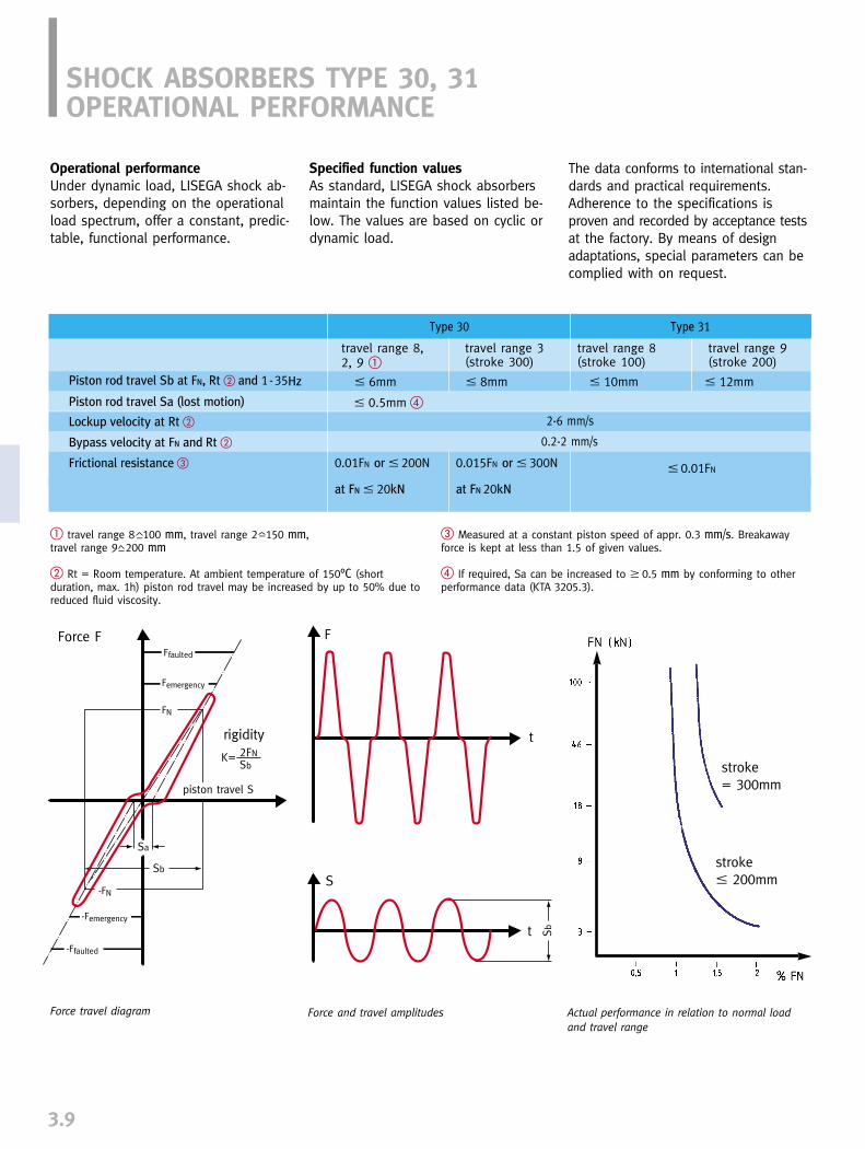
stroke � 200mm
SHOCK ABSORBERS TYPE 30, 31OPERATIONAL PERFORMANCE
3.9
� travel range 8 100 mm, travel range 2 150 mm, travel range 9 200 mm
� Rt = Room temperature. At ambient temperature of 150°C (short duration, max. 1h) piston rod travel may be increased by up to 50% due toreduced fluid viscosity.
� Measured at a constant piston speed of appr. 0.3 mm/s. Breakawayforce is kept at less than 1.5 of given values.
� If required, Sa can be increased to � 0.5 mm by conforming to otherperformance data (KTA 3205.3).
travel range 8, travel range 3 travel range 8 travel range 92, 9 � (stroke 300) (stroke 100) (stroke 200)
� 6mm � 8mm � 10mm � 12mm
–
Type 30 Type 31
Piston rod travel Sb at FN, Rt � and 1-35Hz
Piston rod travel Sa (lost motion)
Lockup velocity at Rt �
Frictional resistance �
� 0.5mm �
2-6 mm/s
Bypass velocity at FN and Rt � 0.2-2 mm/s
0.01FN or � 200N 0.015FN or � 300N
at FN � 20kN at FN 20kN
� 0.01FN
Force travel diagram Force and travel amplitudes
Operational performanceUnder dynamic load, LISEGA shock ab-sorbers, depending on the operationalload spectrum, offer a constant, predic-table, functional performance.
Specified function valuesAs standard, LISEGA shock absorbersmaintain the function values listed be-low. The values are based on cyclic ordynamic load.
The data conforms to international stan-dards and practical requirements.Adherence to the specifications is proven and recorded by acceptance testsat the factory. By means of designadaptations, special parameters can becomplied with on request.
Actual performance in relation to normal loadand travel range
––
stroke= 300mm
Force F
rigidity
piston travel S
Ffaulted
-Ffaulted
Femergency
-Femergency
FN
-FN

3.10
absorbers endure these loads whilemaintaining their functional integrity.
The special guide systems of the shockabsorbers make them largely resistantto permanent cyclic operating loads.This is confirmed by proven practicalexperience.
It has to be considered that the rangeof possible influential parameters suchas frequencies, amplitudes, oscillationshapes, impact directions, mono- andmultiaxial effects, as well as possibleoverlapping, permit no uniform definitionof continuous operational vibration.
Operational Stress FactorsLISEGA hydraulic shock absorbers aredesigned as standard for the operationalloads listed below.
The specified values have been con-firmed by German TÜV qualificationtests. Other values can be agreed uponin exceptional cases by design adap-tations.
SHOCK ABSORBERS, TYPE 30, 31PERMISSIBLE STRESS FACTORS 3
Resistance to fatigueProof of operational durability is basedon the following accumulated loadspectrum:
Normal load FN . . . . . .Load cycles
10 % . . . . . . . . . . . . .2,000,00050 % . . . . . . . . . . . . . .100,00080 % . . . . . . . . . . . . . . .20,000
100 % (Level A/B) . . . . . . . . .10,000133 % (Level C) . . . . . . . . . . .100172 % (LeveI D) . . . . . . . . . . . .10
short term max. 1h/temp. cycle max. 40h per year
at 10-150°C
max. 150°C
accumulated
continuous
short term
permanent max. 80°C
max. 150°C
100%
X=1
0.5-1 bar
5 barexcess pressure
105J/kg (107 rad)
Loading due to environmentaltemperature
Relative humidity
Wet steam atmosphere
Energy dose
Ambient pressure
The values cited above refer to a shockabsorber incl. seals and hydraulic fluid.Special values for the fluid only are:
Pour point
Flash point
Ignition point
� 300°C
� 500°C
-50°C
Hydraulic fluid(silicone oil)
The number of cycles corresponds toestimated maximum dynamic stressesfrom diverse load events within a periodof forty years. It also complies with thetest program requirements of the suit-ability tests conducted by the GermanTÜV. The results prove that the shock
Test area for shock absorbers at the Zeven factory, Germany
Testing shock absorbers, type 31Test load 4500kN
Optimum testing is achieved by using computercontrolled test equipment

3.11
MODE OF FUNCTION
Dynamic eventIn the event of a sudden shock, an instan-taneous, secure and almost rigid connectionis produced between the supported com-ponent and the fixed point on the structure.The resulting dynamic loads are at onceconducted into the structural connection anddissipated without any harmful consequences.
Normal operational movements of piping andother components remain however unhindered.
Moments of force can often change directionat random within the framework of complexoscillation spectra. The response frequencyrange for LISEGA shock absorbers is 0.5 -100 Hz.
FUNCTION
Control valvesThe function of LISEGA hydraulic shock ab-sorbers type 30 is controlled by the main con-trol valve (B), axially mounted within thehydraulic piston (A).During the piston movement (� 2mm/s) thevalve is kept open by spring pressure, and
hydraulic fluid flows freely from one side ofthe piston to the other. During rapid pistonmovement (approx. � 2mm/s) above thespeed limit, the resulting fluid flow pressureon the valve plate closes the main valve.The flow of the hydraulic fluid is stoppedand movement blocked. The compressibilityof the fluid cushion has a softening effecton the restriction of the piston. This pre-vents damaging load spikes.For movement in the compressive direction,the compensating valve (D) closes almostsynchronously with the main valve.
If the pressure on the closed valve subsides,e.g. through reversal of the direction of move-ment, the main control valve opens automa-tically when the fluid force falls short of thespring force.
BypassTo prevent the valves from jamming in theblocking position, they are fitted with abypass system.
Function scheme of a shock absorber, type 30
A B C D
SHOCK ABSORBERSMODE OF OPERATION

3.12
This allows limited piston movement undercontinuing load and ensures safe opening ofthe valves by rapid equalization of pressurein both cylinder chambers. The compensa-ting valve works synchronously with themain valve in the same way.
ReservoirFor both variable piston rod positions as wellas for changes in hydraulic fluid volume caused by temperature changes, volume com-pensation takes place through a coaxiallymounted reservoir (C). The link between thereservoir and main cylinder is regulated bythe compensating valve (D).
Large bore shock absorbers type 31The function of the LISEGA shock absorbertype 31 is fundamentally the same as for type30.The special dimensions, however, require adifferent design arrangement of the reservoir(C). The valve assembly also differs.
The valves (B) themselves operate similarlyto those in type 30. The circulation of thefluid is also blocked by closure of the corres-ponding valve in each respective direction ofmovement. This happens whenever a flow-
Function scheme of a shock absorber type 31
A
C
B
speed limit is exceeded. Because the valvesare directly linked to the reservoir, no specialcompensating valve is needed.
Recurrent testingTo facilitate routine maintenance, the controlvalve system is designed for removal with theshock absorber still in place. The valves canthen simply be replaced in the event of arecurrent test by a previously qualified set ofvalves. A special shut-off device is used toprevent loss of oil. The original valves canthen be remotely tested in a surrogate snub-ber and made ready for use again.
3

SHOCK ABSORBERSDESIGN CHARACTERISTICS
3.13
Design characteristicsThe shock absorbers are closed systemswith no external threaded pressureconnections. Individual parts of the unitare assembled without welding bymeans of precision fits and threadedconnections and secured mechanically(see Fig. 3).
For protection against corrosion, LISE-GA shock absorbers are made exclusi-vely from non-corroding materials. Theconnections are made of galvanizedcarbon steel. The guides on piston rods and pistonsare made from a special wear-resistantnon-metallic material (see Fig. 2).
The fluid reservoir is sealed from theatmosphere by a preset piston, so thatslight overpressure in the hydraulicsystem constantly maintains a slightpresetting of the seals.
The control valves are decisive for thedynamic operation of the shock absorber.To achieve high operational accuracy,the valve parameters have been opti-mized by extensive testing and specialcalculation models.
Seals The sealing systems play a vital role inthe long term function of a hydraulicshock absorber. Together with the hyd-raulic fluid and guide bands, the sealsform part of the non-metallic compo-nents of the shock absorber and aretherefore subject to natural ageing andwear. The most important requisite fora lasting sealing effect is the selectionof the right sealing material. A goodmemory for shape retention (compres-sion set) or lowest possible relaxation oftension is thereby an absolute essential.
For optimum exploitation of materialcharacteristics, the shape of the sealsand the design of their locations arealso important.
The optimum combination of the following factors is decisive for functional efficiency:
➜ temperature resistance➜ radiation resistance➜ abrasion resistance, especially
at high frequency vibration➜ good memory for shape retention➜ good dry running qualities➜ limited diffusion tendency into the
metal surfaces ➜ minimal stick/slip drag effect
The material which best meets these requ-irements is a special compound on thebasis of the fluor elastomer VITON. To exploit the special characteristics tothe fullest extent, the following criteriamust also be considered:
➜ special design shapes➜ backing compound materials➜ optimum mixture consistency➜ optimally balanced hardness➜ precision in gliding surfaces➜ design of locations for defined
presetting of seals
Commercially available seals in shockabsorbers do not fulfill these require-ments, and as experience has shown,lead to premature failure. For LISEGAshock absorbers, a specific sealing sys-tem was developed as early as 1984 incooperation with a major seal manufact-urer. Since then, these seals havedemonstrated their worth in practicalapplication.
Alongside other successful qualificationprocedures through artificial ageing andfatigue tests, a qualification test proced-ure was carried out on LISEGA shockabsorbers in 1992 by order of a majorEuropean nuclear utility. The tests cer-tified a maintenance free service life ofat least 23 years in nuclear powerplants under normal operating condi-tions.
Control indicatorsThe piston position of the shock ab-sorbers can be read from all sides bychecking the scale rings on the body ofthe cylinder. The sturdy stainless steelshroud connected to the piston rod pro-tects it from mechanical damage, dirtand heat and also serves as an indicator.
The fluid level of the reservoir is indi-cated by the position of the reservoirpiston. A sight glass can be used forchecking the minimum level in type 30.Type 31 has a marked indicator rodattached to the base of the externalreservoir.
For details of design and materials, see Technical Specifications.
(Fig. 1)
(Fig. 2)
(Fig. 3)

3.14
3SHOCK ABSORBERSFUNCTION TESTS
LISEGA applies a test procedure using the verylatest technology. The test benches operate asdynamic hydro pulse units, with either force-controlled or travel-controlled excitation asdesired. The frequency bands range from 0.5 - 30Hz and the test loads from 0.5 - 5000 kN. Altogether, seven test benchesof various sizes are available for LISEGA indifferent factories. At customers’ request, they are frequently usedon site as mobile units. Several test bencheshave been supplied to different countries to
The particularly stringentrequirements within thenuclear industry demandflawless proof concerningthe functional parametersfor shock absorbers. This applies both to thefirst acceptance test as wellas to recurrent testing.
Acceptance certificate with test diagrams
Frictional resistance (kN)
Quasistatic functional tests
Drag velocity (mm/s)Lock up velocity (mm/s)Bypass velocity (mm/s)
Load after valve activation (kN)Load at bypass velocity (kN)/bleed rate
Dynamic functional tests(Load and travel amplitudes)
displacement (mm)
compression / tension loads (kN)
Load/travel diagram
be used on site by local plant personnel for recurrent testing. Variable test programs permit shock absorbertests for all makes.
All LISEGA test benches are regularly inspected,certified and calibrated by authorized bodies.
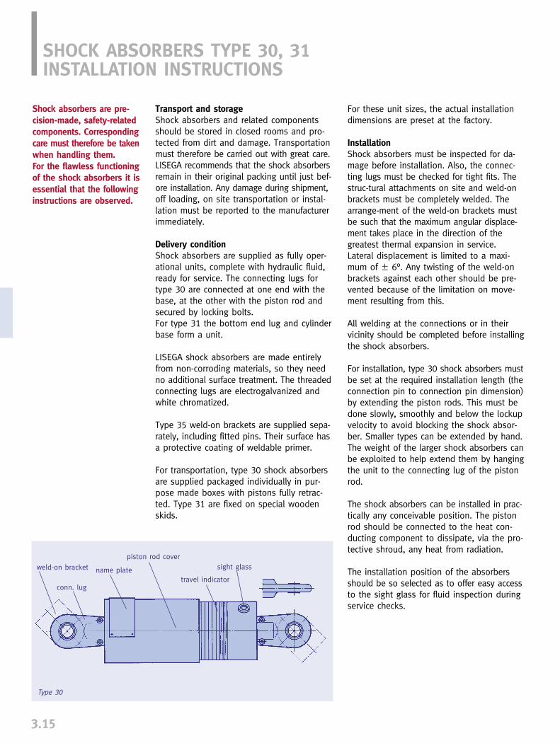
3.15
Shock absorbers are pre-cision-made, safety-relatedcomponents. Correspondingcare must therefore be takenwhen handling them. For the flawless functioningof the shock absorbers it isessential that the followinginstructions are observed.
Transport and storageShock absorbers and related componentsshould be stored in closed rooms and pro-tected from dirt and damage. Transportationmust therefore be carried out with great care.LISEGA recommends that the shock absorbersremain in their original packing until just bef-ore installation. Any damage during shipment,off loading, on site transportation or instal-lation must be reported to the manufacturerimmediately.
Delivery conditionShock absorbers are supplied as fully oper-ational units, complete with hydraulic fluid,ready for service. The connecting lugs fortype 30 are connected at one end with thebase, at the other with the piston rod andsecured by locking bolts. For type 31 the bottom end lug and cylinderbase form a unit.
LISEGA shock absorbers are made entirelyfrom non-corroding materials, so they needno additional surface treatment. The threadedconnecting lugs are electrogalvanized andwhite chromatized.
Type 35 weld-on brackets are supplied sepa-rately, including fitted pins. Their surface hasa protective coating of weldable primer.
For transportation, type 30 shock absorbersare supplied packaged individually in pur-pose made boxes with pistons fully retrac-ted. Type 31 are fixed on special woodenskids.
For these unit sizes, the actual installationdimensions are preset at the factory.
InstallationShock absorbers must be inspected for da-mage before installation. Also, the connec-ting lugs must be checked for tight fits. Thestruc-tural attachments on site and weld-onbrackets must be completely welded. Thearrange-ment of the weld-on brackets mustbe such that the maximum angular displace-ment takes place in the direction of thegreatest thermal expansion in service.Lateral displacement is limited to a maxi-mum of � 6°. Any twisting of the weld-onbrackets against each other should be pre-vented because of the limitation on move-ment resulting from this.
All welding at the connections or in theirvicinity should be completed before installingthe shock absorbers.
For installation, type 30 shock absorbers mustbe set at the required installation length (theconnection pin to connection pin dimension)by extending the piston rods. This must bedone slowly, smoothly and below the lockupvelocity to avoid blocking the shock absor-ber. Smaller types can be extended by hand.The weight of the larger shock absorbers canbe exploited to help extend them by hangingthe unit to the connecting lug of the pistonrod.
The shock absorbers can be installed in prac-tically any conceivable position. The pistonrod should be connected to the heat con-ducting component to dissipate, via the pro-tective shroud, any heat from radiation.
The installation position of the absorbersshould be so selected as to offer easy accessto the sight glass for fluid inspection duringservice checks.
Type 30
weld-on bracket
conn. lug
name plate
piston rod cover
travel indicator
sight glass
SHOCK ABSORBERS TYPE 30, 31INSTALLATION INSTRUCTIONS

~
3.16
3Welding the weld-on bracketsThe following procedure is recommended forthe welding of weld-on brackets:
The minimum weld seam thickness “a“ fortype 35 weld-on brackets is dependent onthe angular displacement and . A per-missible stress of 90N/mm2 at load caseLevel A formed the basis of the calculation.
If the angular displacement increases to90°, the permissible loads are reduced byapproximately 15% at a constant weld seamthickness (a min at = 45°).For permissible loads, see load table inTechnical Specifications, page 0.5
Welding procedure1. Remove pins from weld-on brackets2. Preheat weld-on brackets, from
type 35 79 19 onwards, to 100°C3. Use base electrodes4. Welding should be performed in layers
to avoid welding distortion. (For sequence, see diagram)
5. Allow bracket to cool to 100°C after each welding layer
Type 31
=15˚= 6˚
=30˚= 6˚
=45˚= 6˚
The connections to the various attachmentstructures must be form-fit for load actu-ation. All threaded connections in the flux offorce must be tightened with sufficient torque.
If, after installation, any welding on theattachment structure is performed near theinstalled shock absorber, care must be takenthat no welding current strays through thebody of the snubber.
After installing the complete system, it isrecommended that each unit be inspectedfor the following:
A. Correct fitting of form-fit connections forload actuation (locking screws on the connec-ting lugs, secure pins, threaded connec-tions).
B. All installation points must be checkedfor adequate freedom of movement duringthermal expansion. Care must be taken toallow the connecting lugs to move freely inthe connection brackets and care also takento prevent the piston from reaching the endposition.
For the piston position, a safety zone of 10mm at each end of the cylinder stroke isrecommended. The position can be read fromthe travel scale.
Before commissioning the plant, a full visualinspection of all shock absorbers and instal-lation situations is recommended.
weld-on bracketconn. lug
name plateball bushing
travel indicator
fluid level indicator
removable valves
a a aType
35 19 1335 29 1335 39 1335 49 1335 59 1935 69 1935 79 1935 89 1935 99 1135 09 1335 20 19
3.03.03.03.05.57.5
10.514.515.014.023.0
3.03.03.04.07.09.5
13.518.020.017.0–
3.03.03.05.08.0
11.015.521.023.019.0–
~

For normal operating conditions shock absor-bers are designed to function for the entire40 year life of a plant. The seals and hyd-raulic fluid should be changed at least onceduring this period, at the latest after 20years.
However, under certain conditions (extremestresses) shock absorbers can experience pre-mature ageing and increased mechanical wear.Preventive maintenance is recommended inorder to make sure the shock absorbers re-main fully operational and reliable. This main-tenance is the responsibility of the plant ope-rators.
Measures
1. Regular inspection -visual inspection, once per year
2. Extended inspection -function tests, 12 years after commissioning at the latest.
ImplementationInspection and maintenance work should becarried out by specially trained personnel.LISEGA servicing specialists can do this ifrequired. For dynamic function tests, qualifiedtest benches which can also be brought tothe plant are available.
1. Regular inspectionRegular inspection should involve a visualinspection carried out once a year on all unitsinstalled. The first inspection should takeplace immediately before commissioning.
During the regular inspection, not only theshock absorbers must be inspected, but alsothe environmental conditions and installationsituation. The check list should include thefollowing points:
➜ all units to be inspected, noting installation position
➜ planned operational connection displacements
➜ special environmental or operating conditions.
➜ any maintenance work previously carried out.
3.17
Mobile computer controlled LISEGAtest bench in a Belgian nuclearpower plant
SHOCK ABSORBERSMAINTENANCE RECOMMENDATIONS
Shock absorbers are com-ponents of great safety-related significance for aplant. They offer protec-tion to the piping systemand other componentsagainst dynamic over-loading due to unplannedload events. As these areunpredictable, the comp-lete functional safety of theshock absorbers must beguaranteed at all times.

3.18
The following should be checked at theinstalled position:
➜ Conformity of name plate data with check list.
➜ Correct form fitting of all connections for load actuation
➜ Correct freedom of movement of shock absorber during operating displacements
➜ Position of main piston rod as regards sufficient stroke, including travel reserve (min. 10 mm).
➜ Exterior condition of shock absorber for any damage or leakage.
➜ Surrounding area for possible signs of unusual operating conditions, e.g. increased temperature
➜ Fluid indicator level
As long as the reservoir piston cannot beseen through the sight glass there is suffi-cient fluid in the reservoir. If the piston isvisible, it must be assumed that fluid hasbeen lost.
Observations and findings are to be recordedon the check list and if required, recommen-dations for corrective action made.
2. Extended inspectionAn extended inspection is carried out after12 years of operation, whereby a number ofinstalled shock absorbers (min. 2 units pertype) are subjected to an additional functiontest. After successful testing, the shock ab-sorbers can be reinstalled for further service. In the event of deviations in performance,the shock absorber in question should bedismantled and the function-related parts in-spected. The plant operators are responsiblefor taking and documenting any correctivemeasures.
The scope of testing and the selection ofshock absorbers should be agreed on by therelevant plant department and the serviceengineer responsible. Special considerationis to be given to various stress factors (temperature, radiation, loads, operationalvibrations).
The timing and scope of the next ExtendedInspection is to be decided on the basis ofinspection results recorded.
After approximately 20 years of operation atthe latest, it is recommended that the hydraulicfluid and seals are replaced in all shockabsorbers. Following this work, carried outby trained personnel using original LISEGAspare parts, and after successful functiontesting, the shock absorbers can be usedagain for a further 20 years.
3
Examples of shock absorberinstallation in nuclear plants
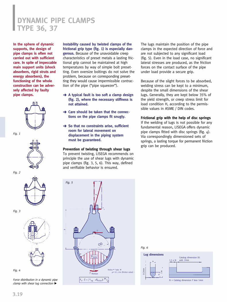
DYNAMIC PIPE CLAMPSTYPE 36, 37
3.19
Instability caused by twisted clamps of thefrictional grip type (fig. 1) is especially dan-gerous. Because of the unavoidable creepcharacteristics of preset metals a lasting fric-tional grip cannot be maintained at hightemperatures by way of simple bolt preset-ting. Even oversize boltings do not solve theproblem, because on corresponding preset-ting they would cause impermissible contrac-tion of the pipe (“pipe squeezer”).
➜ A typical fault is too soft a clamp design (fig. 2), where the necessary stiffness is not attained.
➜ Care should be taken that the connec-tions on the pipe clamps fit snugly.
➜ So that no constraints arise, sufficient room for lateral movement on displacement in the piping system must be guaranteed.
Prevention of twisting through shear lugsTo prevent twisting, LISEGA recommends onprinciple the use of shear lugs with dynamicpipe clamps (fig. 3, 5, 6). This way, definedand verifiable behavior is ensured.
Fig. 1
Fig. 2
Fig. 3
Fig. 4
The lugs maintain the position of the pipeclamps in the expected direction of force andare not subjected to any significant load(fig. 5). Even in the load case, no significantlateral stresses are produced, as the frictionforces on the contact surface of the pipeunder load provide a secure grip.
Because of the slight forces to be absorbed,welding stress can be kept to a minimum,despite the small dimensions of the shearlugs. Generally, they are kept below 35% ofthe yield strength, or creep stress limit forload condition H, according to the permis-sible values in ASME / DIN codes.
Frictional grip with the help of disc springsIf the welding of lugs is not possible for anyfundamental reason, LISEGA offers dynamicpipe clamps fitted with disc springs (fig. 4).Via correspondingly dimensioned sets ofsprings, a lasting torque for permanent frictiongrip can be produced.
Fig. 5
Fig. 6
Lug dimensions
Force distribution in a dynamic pipeclamp with shear lug connection �
lug
tube
frictionlug
friction
friction tubeµ= 0.1...0.4 (friction value)
N = Catalog dimension F less 1mm
1.5 x N
0-2m
m
Catalog dimension B1add. 2mm
In the sphere of dynamicsupports, the design ofpipe clamps is often notcarried out with sufficientcare. In spite of impeccablemain support units (shockabsorbers, rigid struts andenergy absorbers), the functioning of the wholeconstruction can be adver-sely affected by faultypipe clamps.
OD
OODD

If no special arrangement is ordered, thebracket connection is so fitted that the mainangulation range runs along the axis of thepipe. For type 37, the weld-on bracket is tobe ordered separately.
3LISEGA standard designTo provide the ideal solution for all areas ofapplication and at the same time achievethe most favorable performance weight ratios, LISEGA offers four standard designs.
Dynamic pipe clamps as hanger clampsThe given permissible loads have been cal-culated for dynamic operation with shockabsorbers / rigid struts in accordance with thedynamic load spectra shown on page 3.10.
In special cases the dynamic clamps are fittedas hanger clamps, under permanent staticload. In this case, the given permissible loadshave to be reduced as per the following table:
Special designsIn some cases, special designs can be a use-ful alternative to pipe clamps types 36 and37. Especially in cases of parallel and angu-lated arrangements, standardized designand calculation methods have proven theirworth.
SelectionThe selection tables are divided according topipe diameters. Via the temperature rangesand the permissible loads, the type designa-tion for the appropriate clamp is found. Afterthat, the installation dimensions are to bechecked using the drawing. Special attentionmust be given to the lug connections of shockabsorbers, energy absorbers or rigid struts.If the standard pin connection d1 does notfit, another appropriate weld-on bracket (seepage 3.8) can be provided.
Type 36 .. .1/2/3
Type 37. .. 1/2/3/4/5/6
Type 36 .. .4/5
Type 37 .. .7/8/9
3.20
pipe clamp permissibletemperature material permanent
tensile stress
until 350°C S235JRG2 / S355J2G3 100%450°C 16Mo3 90%500°C 16Mo3 55%510°C 13CrMo4-5 65%530°C 13CrMo4-5 55%560°C 13CrMo4-5 45%
This calculation applies to creep strengths dep. on timein the range of 200,000h at temperatures � 450°C.
Special clamp for angular arrangement
Dynamic axial pipe clamp with shock absorbers
Type 36 Type 37

3.21
� Calculation of interimvalues: linear interpolation.
� The connecting load grouphas to be stated in the order.On selection of a lower loadgroup than stated in the table,the E dim. of the clamp is re-duced in accordance with the E dim. of the weld-on bracket(see page 3.8).
� Lug dimensions: F less 1mm;B1 plus 2mm (see page 3.19).
Type 36 .. .1
DYNAMIC PIPE CLAMP SELECTION TABLE OD 33.7 - OD 108.0
°C Emax� Ad1� B B1 kgF�max.�Load gr.250 350 450 500 510 530 560100
4.0 4.0 4.04.0 4.0
4.0 3.9 2.9
101010
110155160
757575
505050
202020
999
222
Type
36 03 1136 03 2136 03 31
permissible laod (kN) �
°C Emax� Ad1� B B1 kgF�max.�Load gr.250 350 450 500 510 530 560100
permissible load (kN) �
°C Emax� Ad1� B B1 kgF�max.�Load gr.250 350 450 500 510 530 560100Type
36 05 1136 05 2136 05 31
permissible load (kN) �
°C Emax� Ad1� B B1 kgF�max.�Load gr.250 350 450 500 510 530 560100Type
36 06 1136 06 2136 06 31
permissible load (kN) �
°C Emax� Ad1� B B1 kgF�max.�Load gr.250 350 450 500 510 530 560100Type
36 07 1136 07 2136 07 31
permissible load (kN) �
OD 33.7 (ND 25)
OD 42.4 (ND 32)
OD 48.3 (ND 40)
OD 60.3 (ND 50)
OD 73.0 (ND 65)
°C Emax� Ad1� B B1 kgF�max.�Load gr.250 350 450 500 510 530 560100Type
36 08 1136 08 2136 08 31
permissible load (kN) �
°C Emax� Ad1� B B1 kgF�max.�Load gr.250 350 450 500 510 530 560100Type
36 09 1136 09 2136 09 31
permissible load (kN) �
°C Emax� Ad1� B B1 kgF�max.�Load gr.250 350 450 500 510 530 560100Type
36 10 1136 10 2136 10 31
permissible load (kN) �
OD 76.1 (ND 65)
OD 88.9 (ND 80)
OD 108.0 (ND 100)
Type
36 04 1136 04 2136 04 31
8.0
8.0
16
15
15
23
32 29 2418 15
13 11 8.1
201515
205265270
165165165
505050
353530
111111
544
4.96.55.5
20 1918 15
14 11 8.3
201515
185230235
146146146
505050
303030
111111
544
3.84.54.3
14 138.0 7.7
7.0 5.8 4.3
151212
160210215
125125125
505050
252525
999
433
2.22.72.7
14 128.0 7.6
6.9 5.8 4.2
151212
160210215
120120120
505050
252525
999
433
2.22.72.6
14 118.0 8.0
7.2 6.1 4.4
151212
150190195
110110110
505050
252525
999
433
1.92.22.2
8.0 7.46.5 5.1
4.0 4.0 2.9
121210
130175175
909090
505050
202020
999
332
1.21.51.4
8.0 8.06.4 5.1
4.0 3.9 2.9
121210
130175175
858585
505050
202020
999
332
1.21.41.3
0.91.11.1

3.22
� Calculation of interim values: linear interpolation.
� The connecting load group has to be stated in the order. On selection of a lower load group than stated inthe table. the E dim. of the clamp is reduced in accordance with the E dim. of the weld-on bracket (see page 3.8).
� Lug dimensions: F less 1mm; B1 plus 2mm (see page 3.19).
Type 36 .. .1/2
Type 36 .. .4
DYNAMIC PIPE CLAMP SELECTION TABLE OD 114.3 - OD 168.3
°C Emax� Ad1� B B1 kgF�max.�Load gr.250 350 450 500 510 530 560100Type
36 11 1136 11 2136 11 2436 11 3136 11 34
permissible load (kN) �
°C Emax� Ad1� B B1 kgF�max.�Load gr.250 350 450 500 510 530 560100Type
36 13 1136 13 2136 13 2436 13 3136 13 34
permissible load (kN) �
OD 114.3 (ND 100)
OD 133.0 (ND 125)
°C Emax� Ad1� B B1 kgF�max.�Load gr.250 350 450 500 510 530 560100Type
36 14 1136 14 2136 14 2436 14 3136 14 34
permissible load (kN) �
OD 139.7 (ND 125)
°C Emax� Ad1� B B1 kgF�max.�Load gr.250 350 450 500 510 530 560100Type
36 16 1136 16 2136 16 2436 16 3136 16 34
permissible load (kN) �
OD 159.0 (ND 150)
°C Emax� Ad1� B B1 kgF�max.�Load gr.250 350 450 500 510 530 560100Type
36 17 1136 17 1236 17 2136 17 2236 17 2436 17 3136 17 3236 17 34
permissible load (kN) �
OD 168.3 (ND 150)
31
31
31
30
2951
2645
2333
172843
132534
121855
101746
7.71333
2030152030151530
270270315315340320320345
230245225240225225240240
50505050
1005050
100
3545304060304080
1111111113111116
56456446
7.611.58.3
10.918.77.7
10.526.0
27 241843
1434
1232
1027
7.819
2015301520
245300335310320
220215215215215
5050
10050
100
3530603060
1111131113
54645
6.77.5
17.97.2
15.4
28 231843
1434
1232
1027
7.919
2015301520
230285320295305
200200200200200
5050
10050
100
3530603060
1111131113
54645
6.06.7
16.26.4
14.3
28 231840
1437
1333
1127
8.018
2015201520
225275285285295
190190190190190
5050
10050
100
3530603060
1111131113
54545
5.86.3
12.86.1
13.0
28 241840
1535
1332
1026
8.016
2015201520
210270280280290
175175175175175
5050
10050
100
3535603060
1111131113
54545
5.16.5
11.75.5
11.8
3

3.23
Type 36 .. .1/2
Type 36 .. .4/5
� Calculation of interim values: linear interpolation.
� The connecting load group has to be stated in the order. On selection of a lower load group than stated inthe table, the E dim. of the clamp is reduced in accordance with the E dim. of the weld-on bracket (see page 3.8).
� Lug dimensions: F less 1mm; B1 plus 2mm (see page 3.19).
DYNAMIC PIPE CLAMP SELECTION TABLE OD 193.7 - OD 267.0
°C Emax� Ad1� B B1 kgF�max.�Load gr.250 350 450 500 510 530 560100Type
36 19 1136 19 1236 19 2136 19 2236 19 2436 19 3136 19 3236 19 34
permissible load (kN) �
OD 193.7 (ND 175)
°C Emax� Ad1� B B1 kgF�max.�Load gr.250 350 450 500 510 530 560100Type
36 22 1136 22 1236 22 2136 22 2236 22 2436 22 3136 22 3236 22 34
permissible load (kN) �
OD 219.1 (ND 200)
°C Emax� Ad1� B B1 kgF�max.�Load gr.250 350 450 500 510 530 560100Type
36 24 1136 24 1236 24 2136 24 2236 24 2436 24 2536 24 3136 24 3236 24 3436 24 35
permissible load (kN) �
OD 244.5 (ND 225)
°C Emax� Ad1� B B1 kgF�max.�Load gr.250 350 450 500 510 530 560100Type
36 26 1136 26 1236 26 2136 26 2236 26 2436 26 2536 26 3136 26 3236 26 3436 26 35
permissible load (kN) �
OD 267.0 (ND 250)
5065
4965
4965
4965
4457
3848
294374
110
23355887
18325278
17274366
13193247
30302030305015203030
335335410410410425410410435435
345350340350340350340350340350
50505050
1001005050
100100
45454045809040458090
11131113131611131616
6656674566
16.018.516.022.036.050.014.519.037.045.0
4557
3647
294374
109
22355886
18335279
17274466
13183244
30302030305015203030
320320400400400415395395420420
320330320330320330320330320330
50505050
1001005050
100100
45454045809040458090
11131113131611131616
6656674566
15.017.015.021.535.048.013.518.035.043.0
4457
3849
284371
233558
183353
172844
132032
3030203030152030
310310385385385370370395
300300290300290290300290
50505050
1005050
100
4545404580404580
1113111313111316
66566456
14.016.014.020.033.012.516.534.0
4657
3749
274368
233658
183454
172845
131933
3030203030152030
285285355355355350350375
270275265275265265275265
50505050
1005050
100
4545404580404580
1113111313111316
66566456
12.514.013.417.729.012.515.530.0
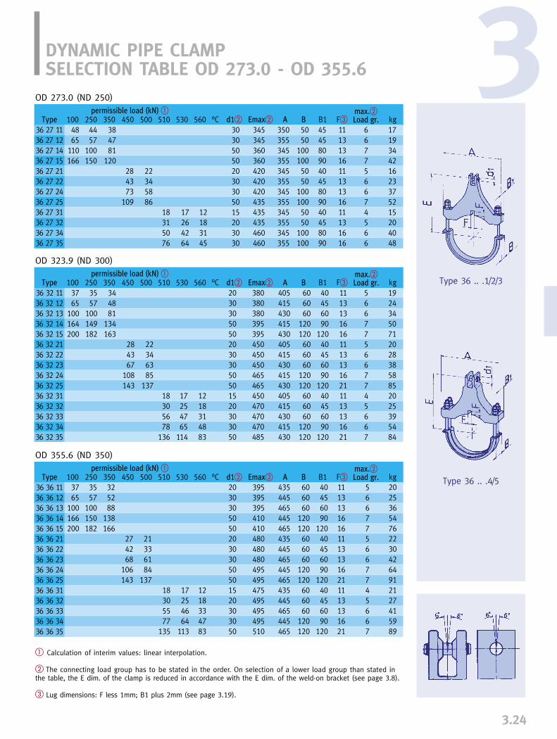
3.24
3
� Calculation of interim values: linear interpolation.
� The connecting load group has to be stated in the order. On selection of a lower load group than stated inthe table, the E dim. of the clamp is reduced in accordance with the E dim. of the weld-on bracket (see page 3.8).
� Lug dimensions: F less 1mm; B1 plus 2mm (see page 3.19).
Type 36 .. .1/2/3
Type 36 .. .4/5
DYNAMIC PIPE CLAMP SELECTION TABLE OD 273.0 - OD 355.6
°C Emax� Ad1� B B1 kgF�max.�Load gr.250 350 450 500 510 530 560100Type
36 27 1136 27 1236 27 1436 27 1536 27 2136 27 2236 27 2436 27 2536 27 3136 27 3236 27 3436 27 35
permissible load (kN) �
OD 273.0 (ND 250)
°C Emax� Ad1� B B1 kgF�max.�Load gr.250 350 450 500 510 530 560100Type
36 32 1136 32 1236 32 1336 32 1436 32 1536 32 2136 32 2236 32 2336 32 2436 32 2536 32 3136 32 3236 32 3336 32 3436 32 35
permissible load (kN) �
OD 323.9 (ND 300)
°C Emax� Ad1� B B1 kgF�max.�Load gr.250 350 450 500 510 530 560100Type
36 36 1136 36 1236 36 1336 36 1436 36 1536 36 2136 36 2236 36 2336 36 2436 36 2536 36 3136 36 3236 36 3336 36 3436 36 35
permissible load (kN) �
OD 355.6 (ND 350)
3765
100164200
3765
100166200
3557
100150182
325288
138166
274268
106143
21336184
13718305577
135
17254664
113
1218334783
203030505020303050501520303050
395395395410410480480480495495475495495495510
435445465445465435445465445465435445465445465
606060
120120606060
120120606060
120120
40456090
12040456090
12040456090
120
111313161611131316211113131621
566775667745667
202536547622304264912127415989
3557
100149182
344881
134163
284367
108143
22346385
13718305678
136
17254765
114
1218314883
203030505020303050501520303050
380380380395395450450450465465450470470470485
405415430415430405415430415430405415430415430
606060
120120606060
120120606060
120120
40456090
12040456090
12040456090
120
111313161611131316211113131621
566775667745667
192434507120283858852025395484
4457
100150
4865
110166
384781
120284373
109
22345886
18315076
17264264
12183145
303050502030305015203030
345345360360420420420435435435460460
350355345355345355345355345355345355
5050
1001005050
1001005050
100100
454580904045809040458090
111313161113131611131616
667756674566
171934421623375215204048

3.25
� Calculation of interim values: linear interpolation.
� The connecting load group has to be stated in the order. On selection of a lower load group than stated inthe table, the E dim. of the clamp is reduced in accordance with the E dim. of the weld-on bracket (see page 3.8).
� Lug dimensions: F less 1mm; B1 plus 2mm (see page 3.19).
Type 36 .. .1/2/3
Type 36 .. .4/5
Type 37 .. .7
DYNAMIC PIPE CLAMP SELECTION TABLE OD 368.0 - OD 406.4
°C Emax� Ad1� B B1 kgF�max.�Load gr.250 350 450 500 510 530 560100
3765
100166279
3557
100151230
344890
139160
274269
106143
21336184
13718305577
135
17254665
113
1217344783
203030506020303050501520303050
400400400415440485485485500500480500500500515
450455475455475450455475455475450455475455475
606060
120120606060
120120606060
120120
40456090
12040456090
12040456090
120
111313161611131316211113131621
566785667745667
212636558723314265932127426091
Type
36 37 1136 37 1236 37 1336 37 1436 37 1536 37 2136 37 2236 37 2336 37 2436 37 2536 37 3136 37 3236 37 3336 37 3436 37 35
permissible load (kN) �
OD 368.0 (ND 350)
°C Emax� Ad1� B B1 kgF�max.�Load gr.250 350 450 500 510 530 560100Type
36 41 1136 41 1236 41 1336 41 1436 41 1536 41 2136 41 2236 41 2336 41 2436 41 2537 41 2736 41 3136 41 3236 41 3336 41 3436 41 3537 41 37
permissible load (kN) �
OD 406.4 (ND 400)
3765
100164277
3556
100149251
344483
137216
274273
105143252
21336183
137244
18295476
133240
16244664
112210
1218334682
136
2030305060203030505060152030305060
430430430445470510510510525525580510530530530545600
485495520495520485495520495520485485495520495520485
606060
120120606060
120120310606060
120120310
40456090
12040456090
12023040456090
120230
1113131621111313162121111313162121
56678566778456678
232840619725344670
1021832329456497
188
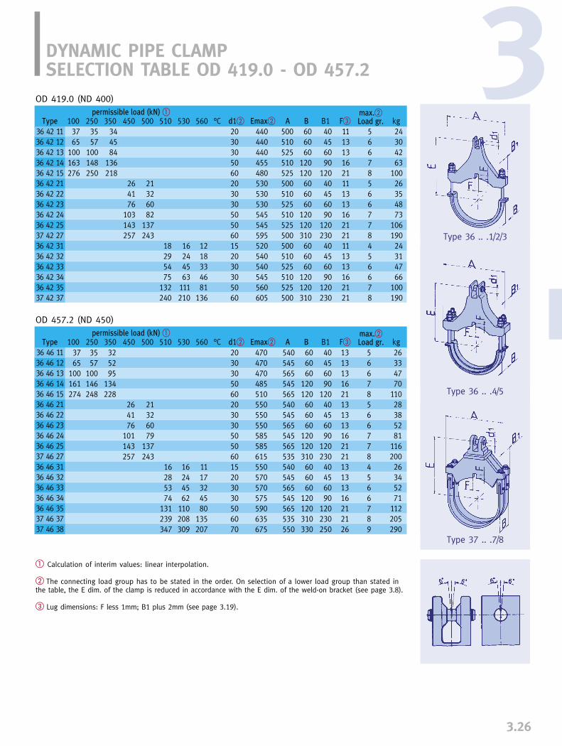
3.26
3
� Calculation of interim values: linear interpolation.
� The connecting load group has to be stated in the order. On selection of a lower load group than stated inthe table, the E dim. of the clamp is reduced in accordance with the E dim. of the weld-on bracket (see page 3.8).
� Lug dimensions: F less 1mm; B1 plus 2mm (see page 3.19).
Type 36 .. .1/2/3
Type 36 .. .4/5
Type 37 .. .7/8
DYNAMIC PIPE CLAMP SELECTION TABLE OD 419.0 - OD 457.2
°C Emax� Ad1� B B1 kgF�max.�Load gr.250 350 450 500 510 530 560100
3765
100163276
3557
100148250
344584
136218
264176
103143257
21326082
137243
18295475
132240
16244563
111210
1218334681
136
2030305060203030505060152030305060
440440440455480530530530545545595520540540545560605
500510525510525500510525510525500500510525510525500
606060
120120606060
120120310606060
120120310
40456090
12040456090
12023040456090
120230
1113131621111313162121111313162121
56678566778456678
24304263
10026354873
10619024314766
100190
Type
36 42 1136 42 1236 42 1336 42 1436 42 1536 42 2136 42 2236 42 2336 42 2436 42 2537 42 2736 42 3136 42 3236 42 3336 42 3436 42 3537 42 37
permissible load (kN) �
OD 419.0 (ND 400)
°C Emax� Ad1� B B1 kgF�max.�Load gr.250 350 450 500 510 530 560100Type
36 46 1136 46 1236 46 1336 46 1436 46 1536 46 2136 46 2236 46 2336 46 2436 46 2537 46 2736 46 3136 46 3236 46 3336 46 3436 46 3537 46 3737 46 38
permissible load (kN) �
OD 457.2 (ND 450)
3765
100161274
3557
100146248
325295
134228
264176
101143257
21326079
137243
16285374
131239347
16244562
110208309
1117324580
135207
203030506020303050506015203030506070
470470470485510550550550585585615550570570575590635675
540545565545565540545565545565535540545565545565535550
606060
120120606060
120120310606060
120120310330
40456090
12040456090
12023040456090
120230250
131313162113131316212113131316212126
566785667784566789
26334770
11028385281
11620026345271
112205290

3.27
� Calculation of interim values: linear interpolation.
� The connecting load group has to be stated in the order. On selection of a lower load group than stated inthe table, the E dim. of the clamp is reduced in accordance with the E dim. of the weld-on bracket (see page 3.8).
� Lug dimensions: F less 1mm; B1 plus 2mm (see page 3.19).
Type 37 .. .1/2/3/4/5/6
Type 37 .. .7/8/9
DYNAMIC PIPE CLAMP SELECTION TABLE OD 508.0 - OD 558.8
°C Emax� Ad1� B B1 kgF�max.�Load gr.250 350 450 500 510 530 560100
75126180270356
57100137195269
4173
100153195
5181
116181211234380
4976
111172201222360
4576
108164198346
377194
149183307
274768
109132201
305060707030505060606070303050606070
515530560600600595620620650650650650625625640665665710
595620630655590575590605625635670605580600600640640605
170170230330310140170180240240250330140170180230240330
130136180260230104130136180190190250104130136180190250
131316212113131621212126131316212626
678996778889667889
4363
104183210406590
148179198295426391
146180310
Type
37 51 1137 51 1237 51 1337 51 1437 51 1737 51 2137 51 2237 51 2337 51 2437 51 2537 51 2637 51 2837 51 3137 51 3237 51 3337 51 3437 51 3537 51 38
permissible load (kN) �
OD 508.0 (ND 500)
°C Emax� Ad1� B B1 kgF�max.�Load gr.250 350 450 500 510 530 560100
permissible load (kN) �
OD 558.8 (ND 550)
74126180270356
56100136195269
4172
100153195
5080
116181211233370
4876
110171201221350
4576
108163198346415
377194
149182304385
275168
108132196265
30506070703050506060607030305060607070
550565595635635640655655680680680725650650665695695735735
645670680705640630640655675685720655625650650690690655670
170170230330310140170180240240250330140170180230240330390
130136180260230104130136180190190250104130136180190250290
13131621211313162121212613131621212626
6789967788896678899
4566
110191226436995
155187206330446695
153188330405
Type
37 56 1137 56 1237 56 1337 56 1437 56 1737 56 2137 56 2237 56 2337 56 2437 56 2537 56 2637 56 2837 56 3137 56 3237 56 3337 56 3437 56 3537 56 3837 56 39

3
3.28
� Calculation of interim values: linear interpolation.
� The connecting load group has to be stated in the order. On selection of a lower load group than stated inthe table, the E dim. of the clamp is reduced in accordance with the E dim. of the weld-on bracket (see page 3.8).
� Lug dimensions: F less 1mm; B1 plus 2mm (see page 3.19).
Type 37 .. .1/2/3/4/5/6
Type 37 .. .7/8/9
DYNAMIC PIPE CLAMP SELECTION TABLE OD 609.6 - OD 660.4
°C Emax� Ad1� B B1 kgF�max.�Load gr.250 350 450 500 510 530 560100
75126182270359540
57100137197272412
4173
100155196300
5080
116180210233367
4876
110171200221347
4576
108162196344413
377193
148182302380
265168
107132195277
3050607070703050506060607030305060607070
575590620660660660670685685715715715760685685700730730770770
695720730755690705680690705725735770705680700700740740705720
170170230330310330140170180240240250330140170180230240330390
130136180260230250104130136180190190250104130136180190250290
1616161621211616162121212616161621212626
67899967788896678899
4768
1141972362954671
1001641972183554769
100161198350430
Type
37 61 1137 61 1237 61 1337 61 1437 61 1737 61 1837 61 2137 61 2237 61 2337 61 2437 61 2537 61 2637 61 2837 61 3137 61 3237 61 3337 61 3437 61 3537 61 3837 61 39
permissible load (kN) �
OD 609.6 (ND 600)
°C Emax� Ad1� B B1 kgF�max.�Load gr.250 350 450 500 510 530 560100
75126182274360540
57100138198273413
4173
100155197300
5279
116180210233366
4976
110170200221347
4677
108164198344413
387294
149183302380
275368
108133195277
3050607070703050506060607030305060607070
605620650690690690700715715750750750790715715730755755795795
750770780805740755730740755775785820755730750750790790755770
170170230330310330145175180240240250330145175180230240330390
130136180260230250110136136180190190250110136136180190250290
1616161621211616162121212616161621212626
67899967788896678899
5073
1202052503105581
1041702072303755580
105168206370455
Type
37 66 1137 66 1237 66 1337 66 1437 66 1737 66 1837 66 2137 66 2237 66 2337 66 2437 66 2537 66 2637 66 2837 66 3137 66 3237 66 3337 66 3437 66 3537 66 3837 66 39
permissible load (kN) �
OD 660.4 (ND 650)

3.29
� Calculation of interim values: linear interpolation.
� The connecting load group has to be stated in the order. On selection of a lower load group than stated inthe table, the E dim. of the clamp is reduced in accordance with the E dim. of the weld-on bracket (see page 3.8).
� Lug dimensions: F less 1mm; B1 plus 2mm (see page 3.19).
Type 37 .. .1/2/3/4/5/6
Type 37 .. .8/9
DYNAMIC PIPE CLAMP SELECTION TABLE OD 711.2 - OD 762.0
°C Emax� Ad1� B B1 kgF�max.�Load gr.250 350 450 500 510 530 560100
75126182275335540
5796
138200244414
4168
100156188300
5279
116182212235368
4976
110172202223350
4778
109165199345415
387294
150184302383
275468
109134195278
3050607070703050506060607030305060607070
635650680720720720725745745770770770815740740755780780825825
800825835860880810780795810830840875810780805805845845810825
170170230330330330145175180240240250330145175180230240330390
130136180260260250110136136180190190250110136136180190250290
1616161621211616162121212616161621212626
67899967788896678899
5375
1242112403255885
1101772152403905984
109173215385475
Type
37 71 1137 71 1237 71 1337 71 1437 71 1537 71 1837 71 2137 71 2237 71 2337 71 2437 71 2537 71 2637 71 2837 71 3137 71 3237 71 3337 71 3437 71 3537 71 3837 71 39
permissible load (kN) �
OD 711.2 (ND 700)
°C Emax� Ad1� B B1 kgF�max.�Load gr.250 350 450 500 510 530 560100
75125182280335400540
56100138216244300414
4170
100156188236300
5179
116182236370
4976
110173223350
4778
109166200347417
387395
151185305385
285369
110135197280
3050607070707030505060607030305060607070
665680710750750750750760775775800800845765765780805805850850
850875885910930935860830845860880925860830855855895895860875
170170230330330330330145175180240250330145175180230240330390
130136180260260260250110136136180190250110136136180190250290
1616161621212116161621212616161621212626
67899996778896678899
5680
1282222472703456290
1131852454106287
113180222405500
Type
37 76 1137 76 1237 76 1337 76 1437 76 1537 76 1637 76 1837 76 2137 76 2237 76 2337 76 2437 76 2637 76 2837 76 3137 76 3237 76 3337 76 3437 76 3537 76 3837 76 39
permissible load (kN) �
OD 762.0 (ND 750)
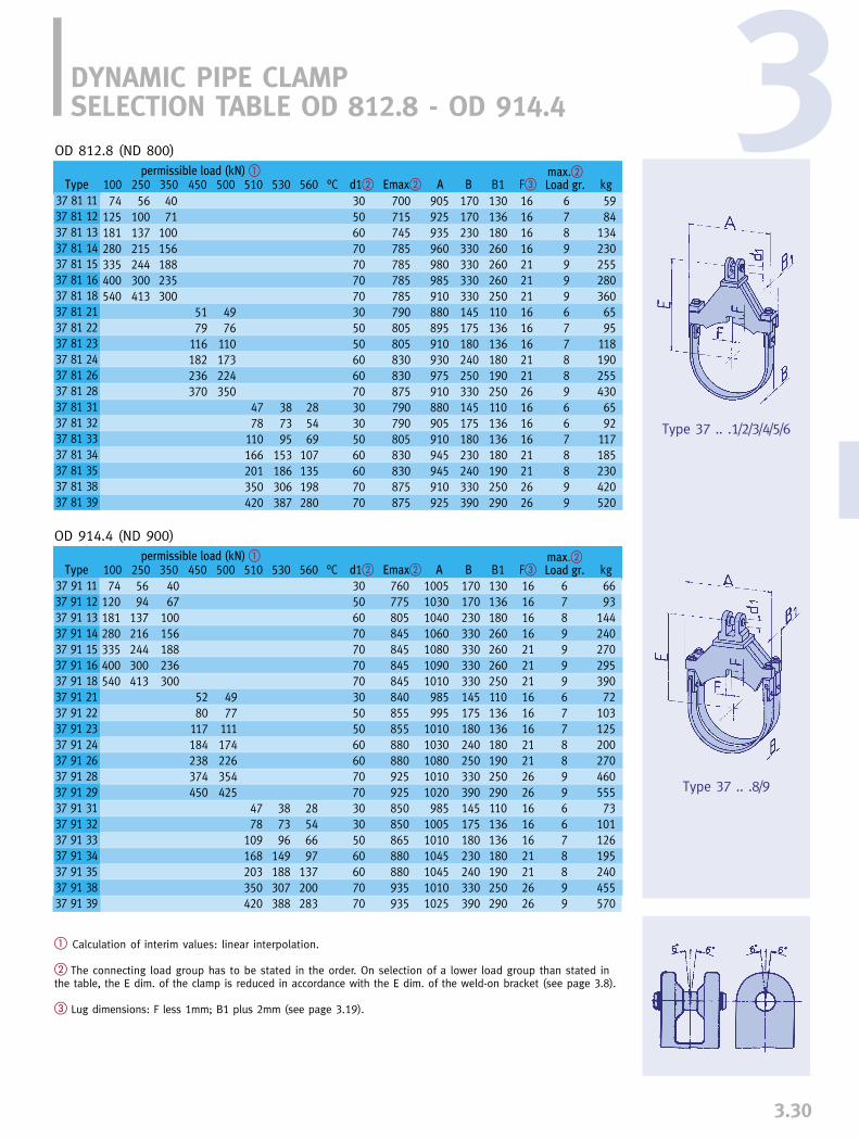
3.30
3
� Calculation of interim values: linear interpolation.
� The connecting load group has to be stated in the order. On selection of a lower load group than stated inthe table, the E dim. of the clamp is reduced in accordance with the E dim. of the weld-on bracket (see page 3.8).
� Lug dimensions: F less 1mm; B1 plus 2mm (see page 3.19).
Type 37 .. .1/2/3/4/5/6
Type 37 .. .8/9
DYNAMIC PIPE CLAMP SELECTION TABLE OD 812.8 - OD 914.4
°C Emax� Ad1� B B1 kgF�max.�Load gr.250 350 450 500 510 530 560100
74125181280335400540
56100137215244300413
4071
100156188235300
5179
116182236370
4976
110173224350
4778
110166201350420
387395
153186306387
285469
107135198280
3050607070707030505060607030305060607070
700715745785785785785790805805830830875790790805830830875875
905925935960980985910880895910930975910880905910945945 910925
170170230330330330330145175180240250330145175180230240330390
130136180260260260250110136136180190250110136136180190250290
1616161621212116161621212616161621212626
67899996778896678899
5984
1342302552803606595
1181902554306592
117185230420520
Type
37 81 1137 81 1237 81 1337 81 1437 81 1537 81 1637 81 1837 81 2137 81 2237 81 2337 81 2437 81 2637 81 2837 81 3137 81 3237 81 3337 81 3437 81 3537 81 3837 81 39
permissible load (kN) �
OD 812.8 (ND 800)
°C Emax� Ad1� B B1 kgF�max.�Load gr.250 350 450 500 510 530 560100
74120181280335400540
5694
137216244300413
4067
100156188236300
5280
117184238374450
4977
111174226354425
4778
109168203350420
387396
149188307388
28546697
137200283
305060707070703050506060707030305060607070
760775805845845845845840855855880880925925850850865880880935935
1005103010401060108010901010985995
10101030108010101020985
100510101045104510101025
170170230330330330330145175180240250330390145175180230240330390
130136180260260260250110136136180190250290110136136180190250290
161616162121211616162121262616161621212626
678999967788996678899
6693
14424027029539072
10312520027046055573
101126195240455570
permissible load (kN) �
OD 914.4 (ND 900)
Type
37 91 1137 91 1237 91 1337 91 1437 91 1537 91 1637 91 1837 91 2137 91 2237 91 2337 91 2437 91 2637 91 2837 91 2937 91 3137 91 3237 91 3337 91 3437 91 3537 91 3837 91 39

3.31
LISEGA dynamic pipe clamps are suppliedready for installation complete with all thenuts and bolts required.It is recommended that units be stored onlyin closed rooms. If storage in the open isunavoidable, they must be protected fromdirt and moisture.
Prevention of twistingTo prevent the clamp from twisting, it isrecommended that a shear lug be welded to the pipe (see also page 3.19). The lug dimensions can be found in the selection tables for dynamic clamps onpages 3.21 – 3.30.
Type 36This design has a solid upper yoke with inte-grated connection bracket and, depending onthe load range, one or two U-bolts with inlayplate are provided.
For installation, remove the preassembled U-bolts. Then place the yoke over the shearlug. Reassemble the U-bolt and inlay fromthe opposite side, tightening the nuts onlylightly at first. Then check and position theclamp as required. Finally, the nuts can beproperly tightened and countered.
DYNAMIC PIPE CLAMPSINSTALLATION INSTRUCTIONS
Type 37This is the heavier type for larger pipe dia-meters and higher loads. Normally, thebracket type 35 is welded to the upper yoke.If the bracket is supplied loose on customerrequest, it must be welded on site followingthe welding instructions on page 3.16. Thecounterpart to the yoke consists of one ortwo flat steel straps depending on load. Thestraps are pinned to the yoke to make trans-port easier. For installation, the straps mustbe removed from the forked blocks by loo-sening the pin connection. The yoke is placed on the shear lug. From the oppositeside the flat steel strap is fitted into the bolt-on clevises, fixed with the pins and securedby cotter pins. The clamp is then checked andpositioned as required.
Finally the nuts are properly tightened. Thehex nuts must be locked in position by ben-ding the tab washers to prevent uninten-tional loosing.
Type 36 .. .1/2/3
Type 37 .. .1/2/3/4/5/6
Type 36 .. .4/5
Type 37 .. .7/8/9

3.32
3
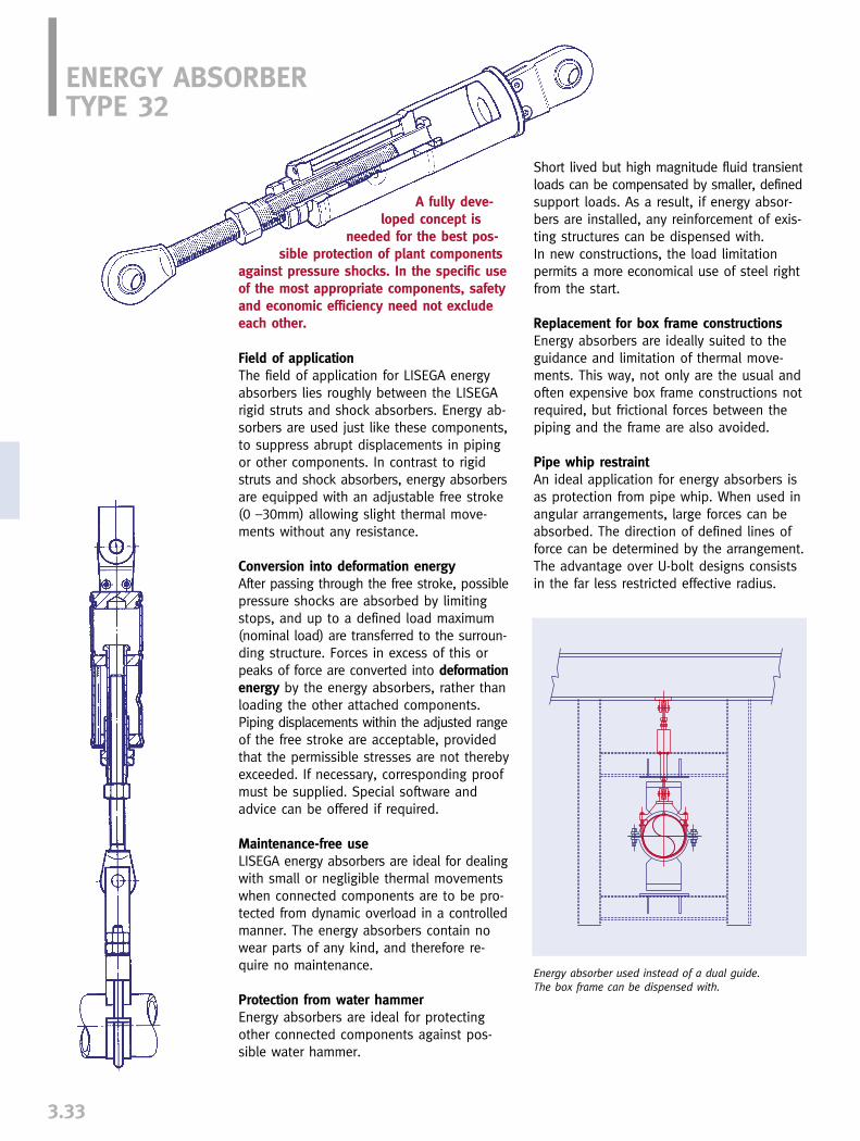
Short lived but high magnitude fluid transientloads can be compensated by smaller, definedsupport loads. As a result, if energy absor-bers are installed, any reinforcement of exis-ting structures can be dispensed with. In new constructions, the load limitation permits a more economical use of steel rightfrom the start.
Replacement for box frame constructionsEnergy absorbers are ideally suited to theguidance and limitation of thermal move-ments. This way, not only are the usual andoften expensive box frame constructions notrequired, but frictional forces between thepiping and the frame are also avoided.
Pipe whip restraintAn ideal application for energy absorbers isas protection from pipe whip. When used inangular arrangements, large forces can beabsorbed. The direction of defined lines offorce can be determined by the arrangement.The advantage over U-bolt designs consistsin the far less restricted effective radius.
ENERGY ABSORBERTYPE 32
A fully deve-loped concept is
needed for the best pos-sible protection of plant components
against pressure shocks. In the specific useof the most appropriate components, safetyand economic efficiency need not excludeeach other.
Field of applicationThe field of application for LISEGA energyabsorbers lies roughly between the LISEGArigid struts and shock absorbers. Energy ab-sorbers are used just like these components,to suppress abrupt displacements in pipingor other components. In contrast to rigidstruts and shock absorbers, energy absorbersare equipped with an adjustable free stroke(0 –30mm) allowing slight thermal move-ments without any resistance.
Conversion into deformation energyAfter passing through the free stroke, possiblepressure shocks are absorbed by limitingstops, and up to a defined load maximum(nominal load) are transferred to the surroun-ding structure. Forces in excess of this orpeaks of force are converted into deformationenergy by the energy absorbers, rather thanloading the other attached components.Piping displacements within the adjusted rangeof the free stroke are acceptable, providedthat the permissible stresses are not therebyexceeded. If necessary, corresponding proofmust be supplied. Special software andadvice can be offered if required.
Maintenance-free useLISEGA energy absorbers are ideal for dealingwith small or negligible thermal movementswhen connected components are to be pro-tected from dynamic overload in a controlledmanner. The energy absorbers contain nowear parts of any kind, and therefore re-quire no maintenance.
Protection from water hammerEnergy absorbers are ideal for protectingother connected components against pos-sible water hammer.
3.33
Energy absorber used instead of a dual guide. The box frame can be dispensed with.
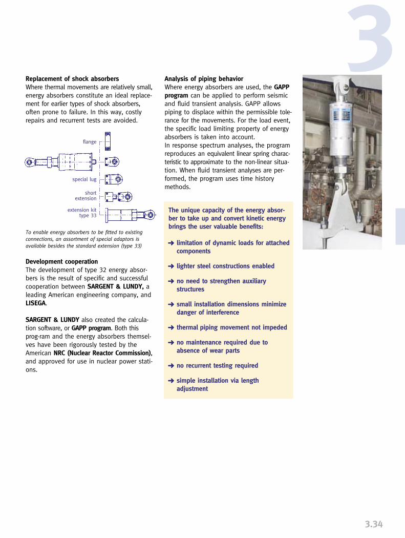
Analysis of piping behaviorWhere energy absorbers are used, the GAPPprogram can be applied to perform seismicand fluid transient analysis. GAPP allowspiping to displace within the permissible tole-rance for the movements. For the load event,the specific load limiting property of energyabsorbers is taken into account. In response spectrum analyses, the programreproduces an equivalent linear spring charac-teristic to approximate to the non-linear situa-tion. When fluid transient analyses are per-formed, the program uses time historymethods.
The unique capacity of the energy absor-ber to take up and convert kinetic energybrings the user valuable benefits:
➜ limitation of dynamic loads for attached components
➜ lighter steel constructions enabled
➜ no need to strengthen auxiliary structures
➜ small installation dimensions minimize danger of interference
➜ thermal piping movement not impeded
➜ no maintenance required due to absence of wear parts
➜ no recurrent testing required
➜ simple installation via length adjustment
Replacement of shock absorbersWhere thermal movements are relatively small,energy absorbers constitute an ideal replace-ment for earlier types of shock absorbers,often prone to failure. In this way, costlyrepairs and recurrent tests are avoided.
Development cooperationThe development of type 32 energy absor-bers is the result of specific and successfulcooperation between SARGENT & LUNDY, aleading American engineering company, andLISEGA.
SARGENT & LUNDY also created the calcula-tion software, or GAPP program. Both thisprog-ram and the energy absorbers themsel-ves have been rigorously tested by theAmerican NRC (Nuclear Reactor Commission),and approved for use in nuclear power stati-ons.
3.34
3flange
special lug
shortextension
extension kittype 33
To enable energy absorbers to be fitted to existingconnections, an assortment of special adaptors is available besides the standard extension (type 33)

3.35
ENERGY ABSORBERS TYPE 32INSTALLATION DIMENSIONS
Individual useThe standard designs shown in the table donot show the full scope of supply possibilities.LISEGA can adapt the products to the specialrequirements of the user.
� When the nominal load is ex-ceeded, the increased force andmovement is converted into de-formation energy.
� Maximum deformation travelin the direction of tension andcompression.
� Dimensions at the midpoint offree strokes t1/t2, and a lengthadjustment of A dimension. When changing t2, E dimension is either reduced or increased.
Order details:Energy absorber type 32 .. 16 t1= … t2= … mmwith two weld-on bracketstype 35 .. ..Marking:…
This especially relates to applications whereload and stroke exceed standard parameters.
total length adjustment min. thread engagement
indicator for absorbed energyfree stroke adjustment
free stroke (tension)free stroke (compression)
on demand
Type
32 18 1632 38 1632 42 1632 52 1632 62 1632 72 1632 82 1632 92 16
Nom.load(kN)� t1 t2 �D �d3
38
1846
100200350550
5.05.05.05.06.59.5
12.5
566080
115130195250
10121520305060
300355440490575715945
18505865
100130165
152022.530456075
9101216223544
85�5095�50
125�75150�75165�75175�75225�75
0-200-220-250-250-250-280-30
0-200-220-250-250-250-280-30
E� A F R SGWeight
(kg)
0.81.83.6
11.518.547.0
105.0
s �

is required, using the adjustment device (H).Corresponding procedures are repeatable upto a maximum deformation travel (s).
InstallationThe energy absorbers correspond to theload groups in Product Group 3 (dynamiccomponents) and are correspondingly loadand connection compatible with otherconnection components of this productgroup. Attention is drawn to the notices onpages 3.3 and 3.15 to 3.16.
Functional qualificationThe LISEGA energy absorbers have undergonea stringent test program to prove their func-tional reliability. Adequate safety marginshave been proven by numerous dynamicand static loading tests.
3.36
3MODE OF OPERATIONAn energy absorber works via an adjustablefree stroke that absorbs thermal movements.The adjustment of this free stroke can bemade in the range of � 25 mm (for a mediumsized design). Within this range the pipe isfree to move without resistance. Dynamicshocks, on the other hand, are limited intheir movement by stops. The resulting forcesare transferred to the surrounding structuresup to the given nominal load, and whenabove that, are transformed into deforma-tion energy by the energy absorber. Thishas the effect of providing a controlled pro-tection from overload for the attached com-ponents.
The unit consists of an austenitic outer sleeve(A) with a defined undersize, into whichtapered bronze disks (B) have been force fitted. The outer sleeve is closed off with abase plate (C), onto which the connectionlug (D) is attached. Forces are transferredthroughout the whole unit by the stops (E)and the shaft (F).
In the event of a dynamic force exceedingthe insertion force of the tapered disks(nominal load), the disk affected is drivenforward and leads to an expansion of thesleeve. This way, the excess forces are keptclear of the attachment structures via con-version into deformation energy. If such aprocess has occurred, the advance of thetapered disk affected can be read off on theindicator rod (G). For further use of the ener-gy absorber, only a corresponding readjust-ment of the free stroke for the new position
ENERGY ABSORBERMODE OF OPERATION
wedge B
free stroke (tension)free stroke (compression)
total length adjustment
free stroke adjustment H indicator for absorbed energy G
FE A C
D
stroke s / mm
load
F / k
N
Tested load/travel characteristics on oscillating loadings� nominal load.
50
30
10
-10
-30
-50
-3 -2 -1
1 2 3

The strut bodies are manufactured in stan-dard lengths. This way, LISEGA rigid strutsare available from stock, TÜV qualificationtested and ASME qualified.
LISEGA rigid struts differ from ordinarydesigns by offering the following advantages:
➜ length adjustable by left hand / right hand threads
➜ no welding
➜ secure locking of joints due to fine threads
➜ favorable performance weight ratios
➜ qualification tested by independentauthority
TasksLISEGA rigid struts type 39 have a numberof important functions for the operationalsafety of piping systems:
➜ Absorption of shocks from unexpected load events. (See page 3.1)
➜ Guidance of pipe systems to control direction of calculated thermal displace-ment direction.
➜ Stabilization of flexible pipe systems by fixing the so-called “zero” positions.
➜ Design of axial stops (“movable” fixed points).
Mode of operation Rigid struts form rigid connections with ballbushings between the piping and structure.No restriction is placed on the limited move-ment of the pipe within the angular displace-ment of the strut. Any movement in the axialdirection of the strut is suppressed.
DesignThe struts consist of a rigid body with a ballbushing joint as a connection at both ends.The structural attachment is formed by a weld-on bracket type 35 (see page 3.8). The con-nection to the piping is formed by the approp-riate dynamic clamp type 36 / 37 (see pages3.21 - 3.30).
The body is made from a tube tapered at theends by forging. The shape corresponds tothe flux of force, and allows a favorable per-formance/ weight ratio. Welding has beencompletely dispensed with. The connectionsare designed as ball bushing joints withturnbuckle function having left hand / righthand threads and enable alength adjustment ina range of
150 or300 mm. Flat
faces are forged on thebody to allow a proper use of
wrench and facilitate length adjustmentsin the installed condition. Fine threads areused on the ball bushing joints to ensuresecure locking.
RIGID STRUTS TYPE 39
3.37
In modern support concepts,rigid struts play an impor-tant role in the optimumsupport system under alloperating conditions.Secure and reliable posi-tioning is a key element inits operational safety andlong life.
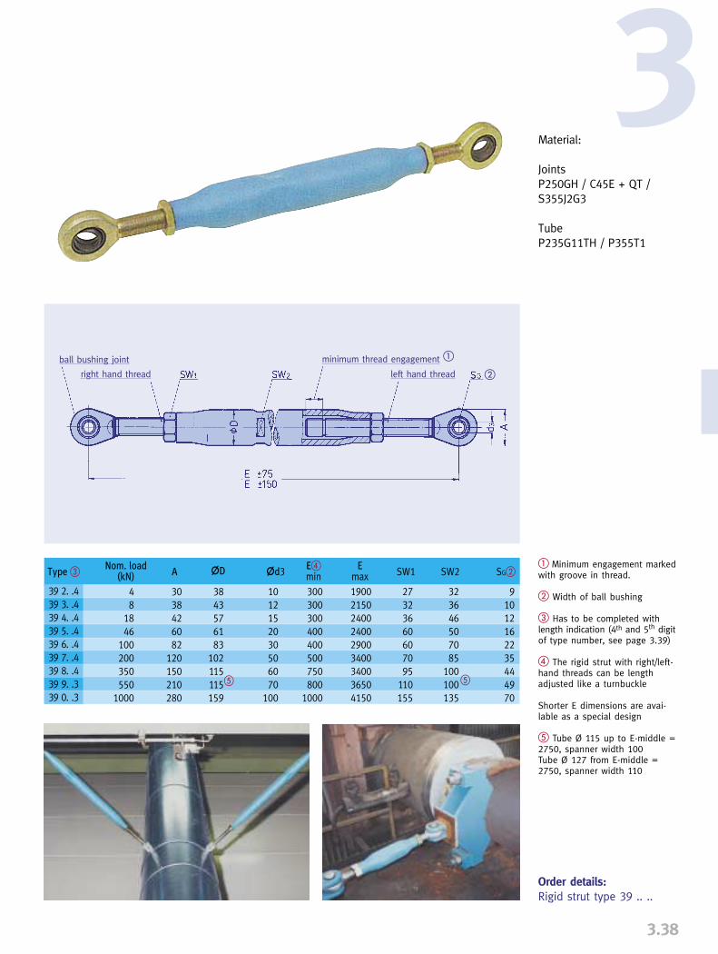
3.38
3
� Minimum engagement markedwith groove in thread.
� Width of ball bushing
� Has to be completed withlength indication (4th and 5th digitof type number, see page 3.39)
� The rigid strut with right/left-hand threads can be lengthadjusted like a turnbuckle
Shorter E dimensions are avai-lable as a special design
� Tube Ø 115 up to E-middle =2750, spanner width 100Tube Ø 127 from E-middle =2750, spanner width 110
Order details:Rigid strut type 39 .. ..
Material:
JointsP250GH / C45E + QT /S355J2G3
TubeP235G11TH / P355T1
ball bushing joint
right hand thread left hand thread
minimum thread engagement �
�
Type �
39 2. .439 3. .439 4. .439 5. .439 6. .439 7. .439 8. .439 9. .339 0. .3
Nom. load(kN) A �D �d3 E�
min SW1 SW2 SG�Emax
48
1846
100200350550
1000
3038426082
120150210280
3843576183
102115115159
1012152030506070
100
300300300400400500750800
1000
190021502400240029003400340036504150
27323660607095
110155
91012162235444970
323646507085
100100135
� �

� The type designation has tobe completed in the 3rd digit bythe load group.
RIGID STRUTSTYPE 39
3.39
SelectionWhen selecting rigid struts from the followingtables, the following should be observed:
1. The given operating load must be coveredby the nominal load.
2. The nominal load determines the load group at the same time.
3. The suitable adjustment range must be selected for the given installation length.
4. The weight is shown at the intersection of load group and adjustment range.
If the intersection is below the dividing line, it is a case of an overlength withreduced load which must be checked in the table on page 3.40 for conformity with the given operating load.
5. For ordering, the type number must be completed at the 3rd digit with the numberof the load group.
Nom. load (kN)46
Load group�5
Weight (kg)
6.47.18.0
1012141617192123(25)(27)(29)(31)
E-middle
375475575750825
10001250150017502000225025002750300032503500375040004250450047505000
8
3
1.92.32.73.1
4.25.26.37.58.5(9.5)
(11 )
18
4
2.73.44,06,3
8.09.5
111314161819(21)(22)(24)
100
6
9.51112
162024283236404448525660(64)(68)(72)(76)
200
7
1821
273339455157647076828995
101107113119
(126)
350
8
42465665758594
104114123133143152162172181191200
Adjustment-range
300 - 450400 - 550500 - 650600 - 900750 - 900850 - 1150
1100 - 14001350 - 16501600 - 19001850 - 21502100 - 24002350 - 26502600 - 29002850 - 31503100 - 34003350 - 36503600 - 39003850 - 41504100 - 44004350 - 46504600 - 49004850 - 5150
Type �
39 .0 3439 .0 4439 .0 5439 .0 7439 .0 8439 .1 0439 .1 2439 .1 5439 .1 7439 .2 0439 .2 2439 .2 5439 .2 7439 .3 0439 .3 2439 .3 5439 .3 7439 .4 0439 .4 2439 .4 5439 .4 7439 .5 04
Permissible load and weights
lengths at reduced loadssee page 3.40
number in ( ) slenderness ratio λ150 � λ � 200
Adjustment-range
800 - 950900 - 1050
1000 - 11501100 - 12501200 - 13501300 - 14501100 - 14001350 - 16501600 - 19001850 - 21502100 - 24002350 - 26502600 - 29002850 - 31503100 - 34003350 - 36503600 - 39003850 - 41504100 - 44004350 - 46504600 - 49004850 - 51505100 - 54005350 - 56505600 - 59005850 - 6150
Nom. load (kN)
Load group�
Weight (kg)
550
9
687277
87100114128142156169183241259277295313331349368385
(403)(420)
1000
0
175183191200
212236260284308332355379403427450475500525545570595620640
E-middle
875975
107511751275137512501500175020002250250027503000325035003750400042504500475050005250550057506000
4
2
1.31.72.02.4
3.24.04.95.8
(6.6)(7.5)
Type �
39 .08339 .09339 .10339 .11339 .12339 .13339 .12339 .15339 .17339 .20339 .22339 .25339 .27339 .30339 .32339 .35339 .37339 .40339 .42339 .45339 .47339 .50339 .52339 .55339 .57339 .603

3.40
3Table of permissible normal loads at normal / excess lengths
The adjacent diagram indi-cates the reduced load valuesas against nominal load thatare to be considered in theevent of overlengths.
Angled arrangement of rigid strutsStock of rigid struts
1000
800
600500
400
300
200
100
80
605040
30
20
10
8
654
3
2
1
1000
800
600500
400
300
200
100
80
605040
30
20
10
8
654
3
2
1
2000 3000 4000 5000 6000
length (mm)
broken line: slenderness ratio: 150 ≤ λ ≤ 200
load
(kN
)
390..3
399..3
397..4
398..4
396..4
395..4
394..4
393..4
392..4

PIPE WHIP RESTRAINTS
3.41
Pipe whip restraintsOne speciality in the area of dynamic pipesupports is the pipe whip restraint. Alongsidethe energy absorber type 32, which providesthe optimum solution to this problem, a U-bolt design for specially large loads hasproven to be highly successful.
Pipe whip restraints are exclusively used inthe nuclear industry. They dampen and absorbthe kinetic energy of bursting pipes in emer-gency cases. For this purpose, the elonga-tion capacity of the encompassing U-bolts isused, as they are designed to absorb theexpected dynamic loads.
Pipe whip restraints have safety-related sig-nificance and are subject to the highest de-mands in quality, design and manufacture. As a large scale supplier to the latest gene-ration of nuclear plants, LISEGA has success-fully proven its qualification to supply thisspecific design.

PIPE CLAMPS, CLAMP BASES, PIPE CONNECTING PARTS
PRODUCT GROUP
4


0
1
2
3
5
6
7
8
9
0
1
2
3
5
6
7
8
9
4
PRODUCTGROUP 4
4.0
PIPE CONNECTION PARTS
Pipe clamps and clamp bases_______________________________________4.1
Horizontal clamps type 42, 43, 44 ___________________________________4.3
Riser clamps type 45, 46, 48 _______________________________________4.4
Clamp bases, type 49______________________________________________4.5
Special designs ___________________________________________________4.7
U-bolts, type 40 __________________________________________________4.8
Weld-on lugs for pipes, type 41_____________________________________4.9
Weld-on lugs for pipe elbows, type 41 ______________________________4.10
Selection of pipe clamps and clamp bases___________________________4.11
Selection overview OD 21.3 - OD 914.4____________________________4.12
Selection overview, temp. 610 – 650°C, OD 33.7 – OD 914.4___________4.46
Lift-off restraints for clamp bases, type 49 ___________________________4.54
Connection plates, type 77 ________________________________________4.55
Installation instructions ___________________________________________4.56
CONTENTS PAGE
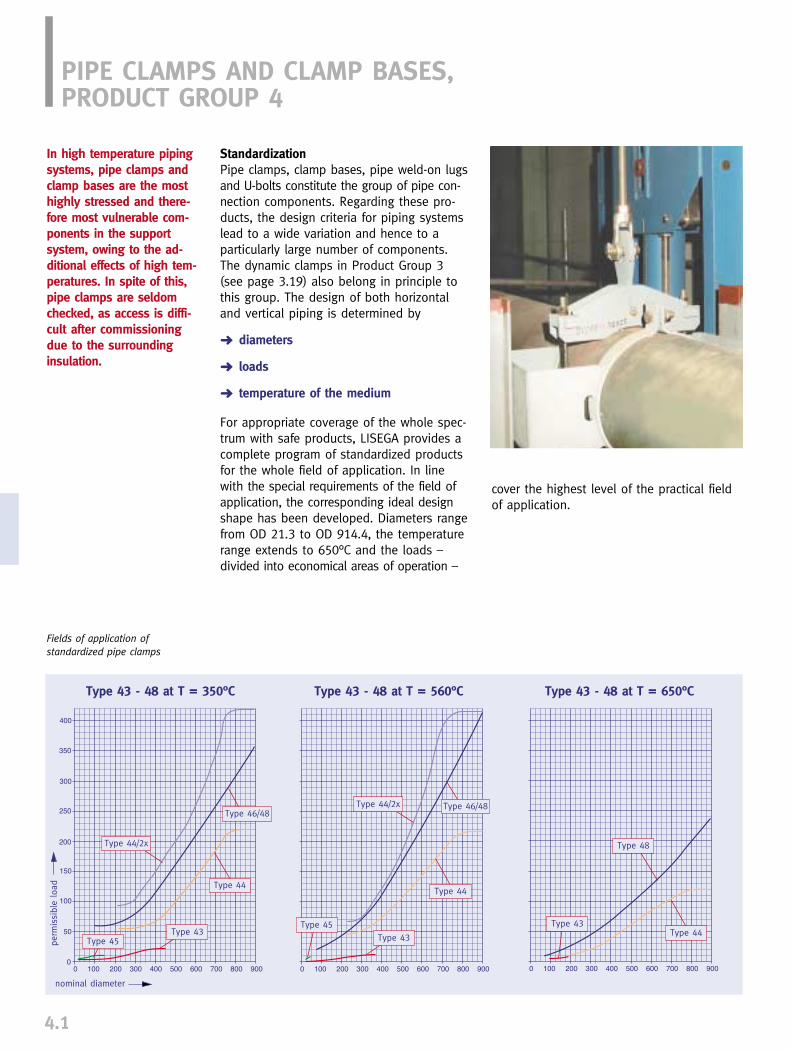
PIPE CLAMPS AND CLAMP BASES,PRODUCT GROUP 4
4.1
StandardizationPipe clamps, clamp bases, pipe weld-on lugsand U-bolts constitute the group of pipe con-nection components. Regarding these pro-ducts, the design criteria for piping systemslead to a wide variation and hence to a particularly large number of components. The dynamic clamps in Product Group 3(see page 3.19) also belong in principle tothis group. The design of both horizontaland vertical piping is determined by
➜ diameters
➜ loads
➜ temperature of the medium
For appropriate coverage of the whole spec-trum with safe products, LISEGA provides acomplete program of standardized productsfor the whole field of application. In linewith the special requirements of the field ofapplication, the corresponding ideal designshape has been developed. Diameters rangefrom OD 21.3 to OD 914.4, the temperaturerange extends to 650°C and the loads – divided into economical areas of operation –
In high temperature pipingsystems, pipe clamps andclamp bases are the mosthighly stressed and there-fore most vulnerable com-ponents in the supportsystem, owing to the ad-ditional effects of high tem-peratures. In spite of this,pipe clamps are seldomchecked, as access is diffi-cult after commissioningdue to the surroundinginsulation.
cover the highest level of the practical fieldof application.
Fields of application of standardized pipe clamps
Type 43 - 48 at T = 350°C Type 43 - 48 at T = 560°C Type 43 - 48 at T = 650°C
nominal diameter
perm
issi
ble
load
Type 44/2x
Type 44/2x
Type 44Type 44
Type 44
Type 48
Type 43Type 43
Type 43
Type 45
Type 45
Type 46/48Type 46/48
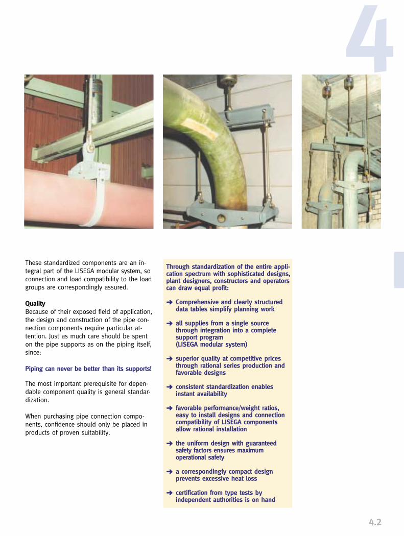
Through standardization of the entire appli-cation spectrum with sophisticated designs,plant designers, constructors and operatorscan draw equal profit:
➜ Comprehensive and clearly structured data tables simplify planning work
➜ all supplies from a single source through integration into a complete support program (LISEGA modular system)
➜ superior quality at competitive prices through rational series production and favorable designs
➜ consistent standardization enables instant availability
➜ favorable performance/weight ratios, easy to install designs and connection compatibility of LISEGA components allow rational installation
➜ the uniform design with guaranteed safety factors ensures maximum operational safety
➜ a correspondingly compact design prevents excessive heat loss
➜ certification from type tests by independent authorities is on hand
4.2
4
These standardized components are an in-tegral part of the LISEGA modular system, soconnection and load compatibility to the loadgroups are correspondingly assured.
QualityBecause of their exposed field of application,the design and construction of the pipe con-nection components require particular at-tention. Just as much care should be spenton the pipe supports as on the piping itself,since:
Piping can never be better than its supports!
The most important prerequisite for depen-dable component quality is general standar-dization.
When purchasing pipe connection compo-nents, confidence should only be placed inproducts of proven suitability.

4.3
HORIZONTAL CLAMPS WITH CONNECTION PARTSTYPE 41, 42, 43, 44
Type 42 .. 17
Typ 41
Type 43
Type 44 .. .4.5.6.7.8.9
Type 44 .. 51.2.3.4.5
Type 44 .. .1.2.3
Type 42 .. .9
Comparison of a LISEGA pipe clamp type 44 with aclamp of traditional design following the same criteria.(Load 32kN, temperature 300°C) �
1. Weld-on lug type 41This type is used principally as a pipe con-nection for piping under 80°C on horizontalpipes or elbows.
Material: S235JRG2
2. Horizontal clamp type 42This clamp can be used as a constructioncomponent or hanger clamp in cold pipingsystems. For larger pipe diameters the loadrange is limited.
Material: S235JRG2
Heat resistant materials(Construction component clamp)Type 42 .. 29 - 16Mo3Type 42 .. 39 - 13CrMo4-5Type 42 .. 49 - 13CrMo9-10/A387 Gr.22
3. Horizontal clamp type 43This hanger clamp corresponds to the tradi-tional shape made from flat steel. Its use islimited to an economical range up to a unitweight of approx. 25kg. Connection to theload chain is made via connecting pins andLISEGA eye nut type 60.
Through the temperature dependence, theload-related application range of the pipeclamps can be extended over a number ofLISEGA load groups. For this, the eye nuts are so designed thatat least 3 corresponding pin diameters canbe accommodated.
Material: S235JRG2, 16Mo313CrMo 4-5, 10CrMo9-10F91(1.4903)
pipe clamp with U-bolt type 44weight 14kg
pipe clamp type 43weight 27kg
4. Horizontal clamp type 44A rigid yoke takes on the load from a pipe-surrounding U-bolt with an inlay plate. Fromcertain diameters, temperatures or load ranges,a flat steel strap is used instead of a U-bolt.
Dispensing completely with weldings, the individual parts are form-fitted with non-weldedconnections and bolted together with threa-ded securing studs. (Patent-No. DE3817059)
The horizontal clamp type 44 is used wheretype 43 reaches its economic limits. This is essentially the high temperature, largediameter or high load range.
Connection to the load chain is made via a lugand LISEGA clevis type 61. The connection lugis designed to accommodate connection pinsof a number of LISEGA load groups.
Material: S235JRG2 / S355J2G316Mo313CrMo4-521CrMoV5-71OCrMo9-1OF91(1.4903)

4.4
4RISER CLAMPS TYPE 45, 46, 48
1. Riser clamp type 45With the riser clamp type 45, the lowerrange suited to this design is covered.
Connection to the vertical piping is made viathe shear lugs welded to the pipe. The designand application of the lugs is the responsib-ility of the piping manufacturer.
Connection to the load chain is made viaconnection pins and LISEGA eye nuts type60. Up to 3 LISEGA load groups can beaccommodated.
When ordering, the desired span (dimension L)is to be given.
Material: S235JRG213CrMo4-5
2. Riser clamp type 46/48The design of this riser clamp exploits the boxshape as the best precondition for the econo-mical use of material. The individual partsare bolted together without weldings viasocket connections.(Patent no. DE3817015)
Connection to the vertically assembled pipingcan be made in two different ways and there-fore demands two different designs:
➜ Type 46 for load support through either 4 or 2 shear lugs welded to the pipe. In general, two lugs are used only at ND � 150mm and are to be so arrangedthat they lie laterally to the longitudinal axis.
➜ Type 48 for load support through trunnions welded to the pipe.
The bore diameter for the trunnions isapproximately 1/3 of the pipe diameter,based on ASME Code case N-392-3 andDIN EN 13480-3. Connection to the load chain is formed byintegrated lugs designed for connection toLISEGA clevises, type 61.The connection lugs are designed to accom-modate the connection pins for a number ofLISEGA load groups.
Riser clamp type 45 with connecting parts
Riser clamp type 46 with connecting parts
Riser clamp type 48 with connecting parts
Special design of a riser clamptype 46� Type 43 with inlay plate � Type 44 with inlay plate
Material: S235JRG2S355J2G316Mo313CrMo4-510CrMo9-10Only for type 48F91(1.4903)
3. Special designs
➜ For equipping austenitic pipe systems, all pipe clamps can be fitted with austenitic inlay plates.
➜ For special diameters not contained in the selection table, corresponding inter-mediate sizes are available or, for minimaldiameter differences, appropriate inlay plates are supplied.
➜ The riser clamp type 48 can quite easily be supplied as a special design in con-junction with LISEGA rigid struts type 39 as an axial stop for both directions, also for dynamic loads (see “Special Designs”on page 4.7).

4.5
CLAMP BASE TYPE 49
Clamp bases are generally used as slidebearings (loose supports) for horizontally arranged piping systems.
As with pipe clamps, the application spec-trum embraces a diameter range of OD 21.3 to OD 914.4mm and a temperaturerange up to 600°C.
Besides the support load, the operationaltemperature of the piping is an essentialdesign criterion in the design of clamp bases.The material to be used is determined bythis. The installation height is governed bythe thickness of the heat insulation.
To keep within a clear level of available sizes,fixed installation heights are assigned to thetemperature ranges.
The fixed installation heights relate, for all diameters, to the respective lower rim of thepipe and have a dimension range of 50 or100mm increments.
The standard dimensions selected for thesupport height of pipes as well as the lengthof the slide bases cover the most commoncases of application.
Different application conditions through temperature and loading demand differentclamp base designs.
If required, components with special dimen-sions can be supplied (see also “SpecialDesigns”, page 4.7).
Possible stress effects on aclamp base
� Clamp base heights dependent on temperature of the medium and pipe diameter.
Temp. up to
350°C
H
pipe Ø
50
21.3-88.9
100
21.3-558.8
150
108-914.4
200
323.9-914.4
Temp. up to
560°C
H
pipe Ø
150
21.3-76.1
200
88.9-168.3
250
193.7-323.9
300
355.6-914.4
Temp. up to
500°C
H
pipe Ø
100
21.3-26.9
150
33.7-76.1
200
88.9-193.7
250
219.1-457.2
300
508-914.4
Temp. up to
600°C
H
pipe Ø
150
21.3-76.1
200
88.9-168.3
250
193.7-323.9
300
355.6-914.4
The load limits in the sel-ection tables on pages 4.12to 4.45 can be exceededby 80%, if the arrange-ment of the clamp basesinvolves seating them on atrapeze or a PTFE slidepad.
Example:Type 49 32 14 at 100°C 20kN acc. to table page 4.32;for use as trapeze basesor on PTFE slide plates thepermissible load amountsto 36kN

4.6
41. Design for lower temperatures and smaller pipe diametersThe design for this field of application consistsof two shaped halves. On installation with thepiping, the lower section of both halves isbolted on firmly and provides the slide base.
In the upper section the pipe is secured inposition via a preset screw.
Through the free space under the pipe al-lowed by the design of the component, con-stant ventilation of the area is assured. This is essential for cold piping systems, be-cause otherwise permanent moisture woulddevelop here after only a short time, causingcorrosion of the piping.
Material: S235JRG2S380MC
2. Design for medium and high temperaturesThis design consists of a shaped lower metalpart firmly welded to two pipe clamps. The lower section is fitted, according to therespective design load, with a reinforcementgusset.
The clamp bases are versatile in application.By the use of two lower sections set againsteach other, a double guide can easily be prod-uced. By the additional application of lateralguides, a manifold guiding system can beprovided. The shape of the support platepermits the simple mounting of lift-offrestraints. The lower section is so designedthat it can be equipped with a stainless steelplate as a sliding surface for a PTFE bearing.
Clamp base for smaller pipe diameters type 49 .. .1, 49 .. .2
Clamp base for medium and hightemperatures type 49 .. .3, .. .4, .. .5
Clamp base type 49 with PTFEslide bearing to standard design.
Material: S235JRG2 16Mo313CrMo4-510CrMo9-10
Applications of clamp bases on trapezes or PTFE see page 4.5.
3. Special designs
➜ For the support of austenitic piping systems,all clamp bases can be fitted with corresponding stainless steel inlay plates.
➜ Special lengths or heights are possible if required. In cases of great expansion it might be more expedient to arrange for correspondingly long support surfaceson site.
➜ The slide bearings of all clamp bases can be supplied as sliding surfaces for a PTFE or graphite bearing.
➜ For special diameters not contained in theselection table, corresponding intermediatesizes are supplied. For minimal diameter differences suitable inlay plates areprovided.
➜ The clamp bases can if required be fitted with lift-off restraints.
➜ Two-fold or manifold guidings using standard clamp bases can be supplied if required (see “Special Designs” on page 4.7).
(Fig. 2) (Fig. 3)(Fig. 1)
��� Clamp base with lift-off restraints, permissible loads and dimensions, see page 4.54 (Fig. 1)
�� Clamp base as double guide(horizontal application) (Fig. 2)
� Clamp base as manifold guide (vertical application) (Fig. 3)
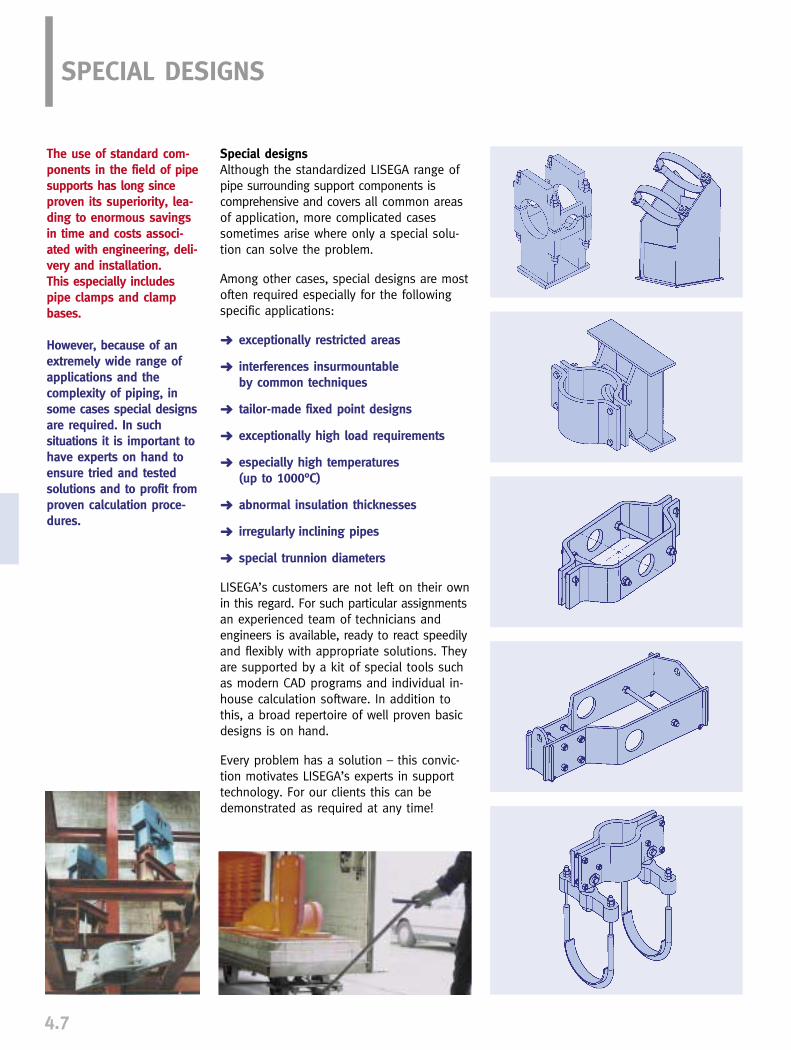
4.7
SPECIAL DESIGNS
Special designsAlthough the standardized LISEGA range ofpipe surrounding support components is comprehensive and covers all common areasof application, more complicated casessometimes arise where only a special solu-tion can solve the problem.
Among other cases, special designs are mostoften required especially for the followingspecific applications:
➜ exceptionally restricted areas
➜ interferences insurmountable by common techniques
➜ tailor-made fixed point designs
➜ exceptionally high load requirements
➜ especially high temperatures (up to 1000°C)
➜ abnormal insulation thicknesses
➜ irregularly inclining pipes
➜ special trunnion diameters
LISEGA’s customers are not left on their ownin this regard. For such particular assignmentsan experienced team of technicians andengineers is available, ready to react speedilyand flexibly with appropriate solutions. Theyare supported by a kit of special tools suchas modern CAD programs and individual in-house calculation software. In addition tothis, a broad repertoire of well proven basicdesigns is on hand.
Every problem has a solution – this convic-tion motivates LISEGA’s experts in supporttechnology. For our clients this can bedemonstrated as required at any time!
The use of standard com-ponents in the field of pipesupports has long sinceproven its superiority, lea-ding to enormous savingsin time and costs associ-ated with engineering, deli-very and installation. This especially includespipe clamps and clampbases.
However, because of anextremely wide range ofapplications and the complexity of piping, insome cases special designsare required. In such situations it is important tohave experts on hand toensure tried and testedsolutions and to profit fromproven calculation proce-dures.

4.8
4U-BOLTSTYPE 40
U-boltstype 40 01 .8 to 40 91 .8
Type 40 serves mainly tosecure piping of max. 80°Ctemp. to secondary steelstructure.
5. digit: 1 = S235JRG2 (St 37)3 = stainless steel 1.4301
OD
A30354053607287
103123130155188238295350381432485537638740790943
(kg)0.050.050.050.150.160.180.300.320.360.370.420.911.082.072.352.552.804.554.905.706.506.908.00
B70707075758595
100115115130155180215245260285320345395450475550
E111317212430374454577084110137162178203229254305356381457
d2 x LM6 x 65M6 x 65M6 x 65M10 x 65M10 x 65M10 x 70M12 x 75M12 x 75M12 x 75M12 x 75M12 x 75M16 x 95M16 x 95M20 x 110M20 x 110M20 x 110M20 x 110M24 x 125M24 x 125M24 x 125M24 x 125M24 x 125M24 x 125
OD21.326.933.742.448.360.373.088.9
108.0114.3139.7168.3219.1273.0323.9355.6406.4457.2508.0609.6711.2762.0914.4
weightType
40 01 .840 02 .840 03 .840 04 .840 05 .840 06 .840 07 .840 09 .840 10 .840 11 .840 14 .840 17 .840 22 .840 27 .840 32 .840 36 .840 41 .840 46 .840 51 .840 61 .840 71 .840 76 .840 91 .8

4.9
WELD-ON LUGS FOR PIPESTYPE 41
Weld-on lugs for pipesType 41 D9 11 to 41 79 12
� Permissible load at 80°C= normal load (load case A)of the corresponding loadgroup (3rd digit of the typedesignation, see “Max.permissible load for staticcomponents”, page 0.5)
Stress present in the givenwelding seam � 50N/mm2
at 4° load angle.Material: S235JRG2
Type 41 .. 11 Smax = 10mmType 41 .. 12 Smax = 100mm
Reduction factors of thepermiss. load at increasedtemperatures:
Order details:Weld-on lug for pipes, type 41 .9 1.
OD
d3A H C tweight(kg)
Type
41 D9 1141 D9 1241 29 1141 29 1241 39 1141 39 1241 49 1141 49 1241 59 1141 59 1241 69 1141 69 1241 79 1141 79 12
R G a
F perm. (T)
0.7 F perm. (80°C)0.5 F perm. (80°C)
T
250°C350°C
30303565457080
12085
130120165170230
10.510.512.512.516.516.520.520.524.524.534344141
2511525
11530
12040
12540
13050
14060
150
151517.517.522.522.5303032.532.540405050
1515222228283737404050506565
1010101010101010101010101010
88
101012121515202025253030
33334.54.54.54.55.55.56.56.56.56.5
0.060.230.110.490.210.750.531.600.752.301.604.103.207.30
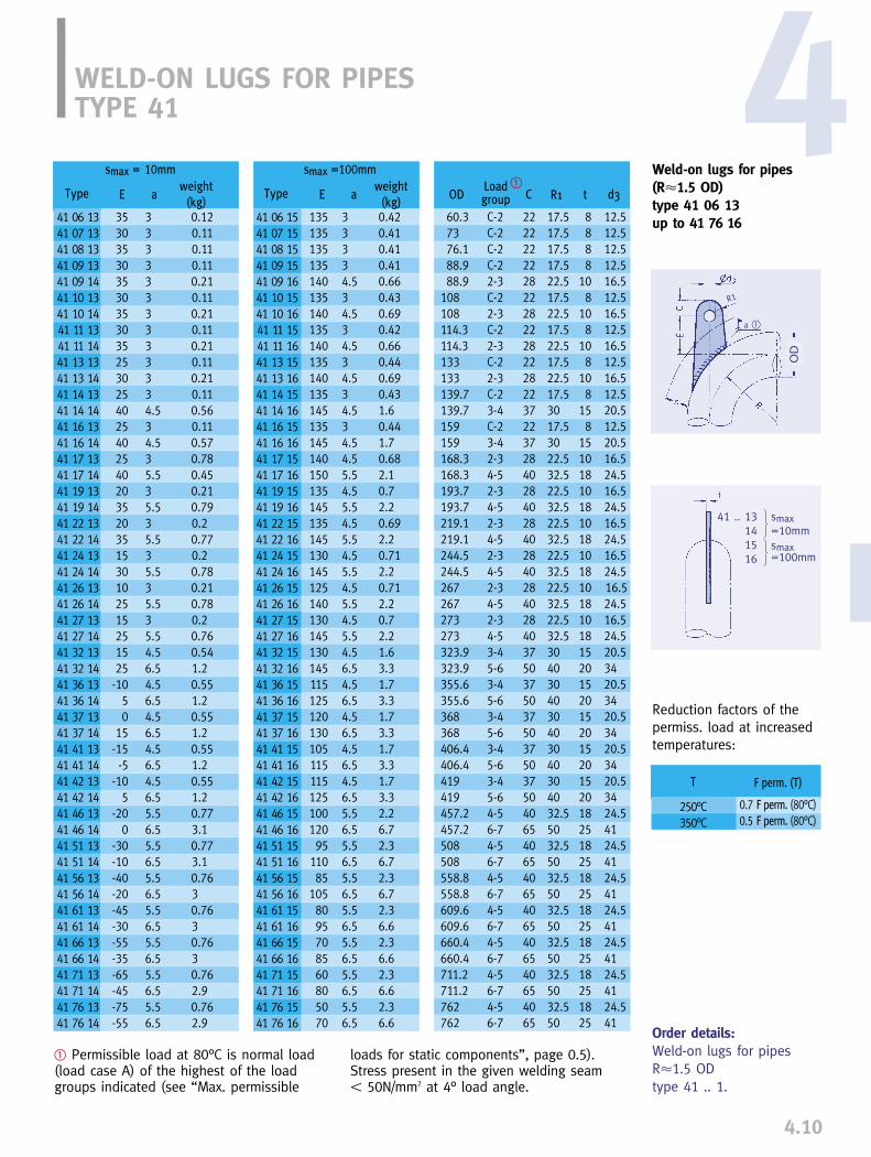
4.10
WELD-ON LUGS FOR PIPES TYPE 41
Weld-on lugs for pipes(R�1.5 OD) type 41 06 13up to 41 76 16
F perm. (T)
0.7 F perm. (80°C)0.5 F perm. (80°C)
T
250°C350°C
Reduction factors of thepermiss. load at increasedtemperatures:
4
� Permissible load at 80°C is normal load(load case A) of the highest of the loadgroups indicated (see “Max. permissible
loads for static components”, page 0.5).Stress present in the given welding seam � 50N/mm2 at 4° load angle.
41 .. 13141516
smax=10mmsmax=100mm
67
86
78
Order details:Weld-on lugs for pipesR�1.5 ODtype 41 .. 1.
R1
a �
OD
weight
(kg)aE
weight
(kg)aE OD
Loadgroup C R1 t d3Type
41 06 1541 07 1541 08 1541 09 1541 09 1641 10 1541 10 1641 11 1541 11 1641 13 1541 13 1641 14 1541 14 1641 16 1541 16 1641 17 1541 17 1641 19 1541 19 1641 22 1541 22 1641 24 1541 24 1641 26 1541 26 1641 27 1541 27 1641 32 1541 32 1641 36 1541 36 1641 37 1541 37 1641 41 1541 41 1641 42 1541 42 1641 46 1541 46 1641 51 1541 51 1641 56 1541 56 1641 61 1541 61 1641 66 1541 66 1641 71 1541 71 1641 76 1541 76 16
Type
41 06 1341 07 1341 08 1341 09 1341 09 1441 10 1341 10 1441 11 1341 11 1441 13 1341 13 1441 14 1341 14 1441 16 1341 16 1441 17 1341 17 1441 19 1341 19 1441 22 1341 22 1441 24 1341 24 1441 26 1341 26 1441 27 1341 27 1441 32 1341 32 1441 36 1341 36 1441 37 1341 37 1441 41 1341 41 1441 42 1341 42 1441 46 1341 46 1441 51 1341 51 1441 56 1341 56 1441 61 1341 61 1441 66 1341 66 1441 71 1341 71 1441 76 1341 76 14
smax = 10mm smax =100mm
3530353035303530352530254025402540203520351530102515251525-10
50
15-15-5
-105
-200
-30-10-40-20-45-30-55-35-65-45-75-55
3333333333334.534.535.535.535.535.535.535.54.56.54.56.54.56.54.56.54.56.55.56.55.56.55.56.55.56.55.56.55.56.55.56.5
0.120.110.110.110.210.110.210.110.210.110.210.110.560.110.570.780.450.210.790.20.770.20.780.210.780.20.760.541.20.551.20.551.20.551.20.551.20.773.10.773.10.7630.7630.7630.762.90.762.9
13513513513514013514013514013514013514513514514015013514513514513014512514013014513014511512512013010511511512510012095
11085
1058095708560805070
33334.534.534.534.534.534.54.55.54.55.54.55.54.55.54.55.54.55.54.56.54.56.54.56.54.56.54.56.55.56.55.56.55.56.55.56.55.56.55.56.55.56.5
0.420.410.410.410.660.430.690.420.660.440.690.431.60.441.70.682.10.72.20.692.20.712.20.712.20.72.21.63.31.73.31.73.31.73.31.73.32.26.72.36.72.36.72.36.62.36.62.36.62.36.6
60.37376.188.988.9
108108114.3114.3133133139.7139.7159159168.3168.3193.7193.7219.1219.1244.5244.5267267273273323.9323.9355.6355.6368368406.4406.4419419457.2457.2508508558.8558.8609.6609.6660.4660.4711.2711.2762762
C-2C-2C-2C-22-3C-22-3C-22-3C-22-3C-23-4C-23-42-34-52-34-52-34-52-34-52-34-52-34-53-45-63-45-63-45-63-45-63-45-64-56-74-56-74-56-74-56-74-56-74-56-74-56-7
222222222822282228222822372237284028402840284028402840375037503750375037504065406540654065406540654065
17.517.517.517.522.517.522.517.522.517.522.517.53017.53022.532.522.532.522.532.522.532.522.532.522.532.53040304030403040304032.55032.55032.55032.55032.55032.55032.550
8888
108
108
108
108
158
15101810181018101810181018152015201520152015201825182518251825182518251825
12.512.512.512.516.512.516.512.516.512.516.512.520.512.520.516.524.516.524.516.524.516.524.516.524.516.524.520.53420.53420.53420.53420.53424.54124.54124.54124.54124.54124.54124.541
�
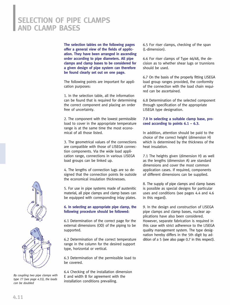
4.11
The selection tables on the following pagesoffer a general view of the fields of applic-ation. They have been arranged in ascendingorder according to pipe diameters. All pipeclamps and clamp bases to be considered fora given design of pipe system can thereforebe found clearly set out on one page.
The following points are important for appli-cation purposes:
1. In the selection table, all the informationcan be found that is required for determiningthe correct component and placing an orderfree of uncertainty.
2. The component with the lowest permissibleload to cover in the appropriate temperaturerange is at the same time the most econo-mical of all those listed.
3. The geometrical values of the connectionsare compatible with those of LISEGA connec-tion components. Via the wide load appli-cation range, connections in various LISEGAload groups can be linked up.
4. The lengths of connection lugs are so de-signed that the connection points lie outsidethe economical insulation thicknesses.
5. For use in pipe systems made of austeniticmaterial, all pipe clamps and clamp bases canbe equipped with corresponding inlay plates.
6. In selecting an appropriate pipe clamp, thefollowing procedure should be followed:
6.1 Determination of the correct page for theexternal dimensions (OD) of the piping to besupported.
6.2 Determination of the correct temperaturerange in the column for the desired supporttype, horizontal or vertical.
6.3 Determination of the permissible load tobe covered.
6.4 Checking of the installation dimension E and width B for agreement with the installation conditions prevailing.
6.5 For riser clamps, checking of the span(L-dimension).
6.6 For riser clamps of Type 46/48, the de-cision as to whether shear lugs or trunnionsshould be used.
6.7 On the basis of the properly fitting LISEGAload group ranges provided, the conformityof the connection with the load chain requi-red can be ascertained.
6.8 Determination of the selected componentthrough specification of the appropriateLISEGA type designation.
7.0 In selecting a suitable clamp base, pro-ceed according to points 6.1 – 6.3.
In addition, attention should be paid to thechoice of the correct height (dimension H)which is determined by the thickness of theheat insulation.
7.1 The heights given (dimension H) as wellas the lengths (dimension A) are standarddimensions and cover the most commonapplication cases. If required, componentsof different dimensions can be supplied.
8. The supply of pipe clamps and clamp basesis possible as special designs for particularuses and conditions (see pages 4.4 and 4.6in this regard).
9. In the design and construction of LISEGApipe clamps and clamp bases, nuclear ap-plications have also been considered.However, separate fabrication is required inthis case with strict adherence to the LISEGAquality management system. The type desig-nation hereby differs in the 5th digit by ad-dition of a 5 (see also page 0.7 in this respect).
SELECTION OF PIPE CLAMPS AND CLAMP BASES
By coupling two pipe clamps withtype 77 (see page 4.55), the loadscan be doubled
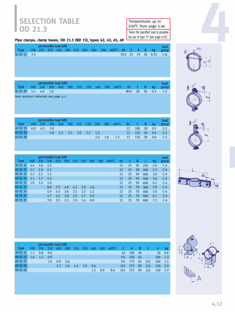
4.12
4Pipe clamps, clamp bases, OD 21.3 (ND 15), types 42, 43, 45, 49
SELECTION TABLEOD 21.3
Type
42 01 17
loadgroup
C-D
permissible load (kN)1002.5
250 350 450 500 530 560 E
22B
26kg
0.14510 A
43
Type
43 01 1943 01 3943 01 49
loadgroup
C-2C-2C-2
permissible load (kN)1006.0
2504.5
3503.05.8
450
5.2
500
3.5
530
2.2
600°C
1.3
d1121212
B
303030
kg
0.50.60.6
510
3.0
E
100135135
Type
45 01 1145 01 1145 01 1145 01 1145 01 1145 01 3145 01 3145 01 3145 01 31
loadgroup
C-4C-4C-4C-4C-4C-4C-4C-4C-4
permissible load (kN)1004.43.72.72.11.9
2503.62.92.21.71.4
3502.52.11.51.21.08.05.94.73.9
450
7.25.44.33.5
500
4.83.62.82.3
530
3.02.21.71.4
600°C d1121212121212121212
B
505050505070707070
kg
2.02.33.03.64.23.95.06.17.2
510
4.23.12.52.0
E
252525252525252525
L
250300400500600300400500600
Type
49 01 1149 01 1249 01 2549 01 3549 01 45
permissible load (kN)1001.11.6
2500.81.2
3500.60.91.0
450
0.92.2
500
0.61.6
530
1.0
600°C
0.6
A
100150175175175
B
4065659090
kg
0.61.31.52.02.3
510
1.4
C
--
225225225
H
50100100150150
Type
42 01 19
loadgroup
C-2
permissible load (kN)1005.5
2504.0
3503.0
450 500 530 d2M10
B
30kg
0.3510 E
28
580 600°C d410.5
600°C560 580
Heat resistant materials see page 4.3
560
1.22.4
580
1.8
560
1.61.20.90.8
580
560
0.61.2
580
0.9
E
61111111161161
Temperatures up to650°C from page 4.46
Twice the specified load is possible by use of type 77 (see page 4.55)
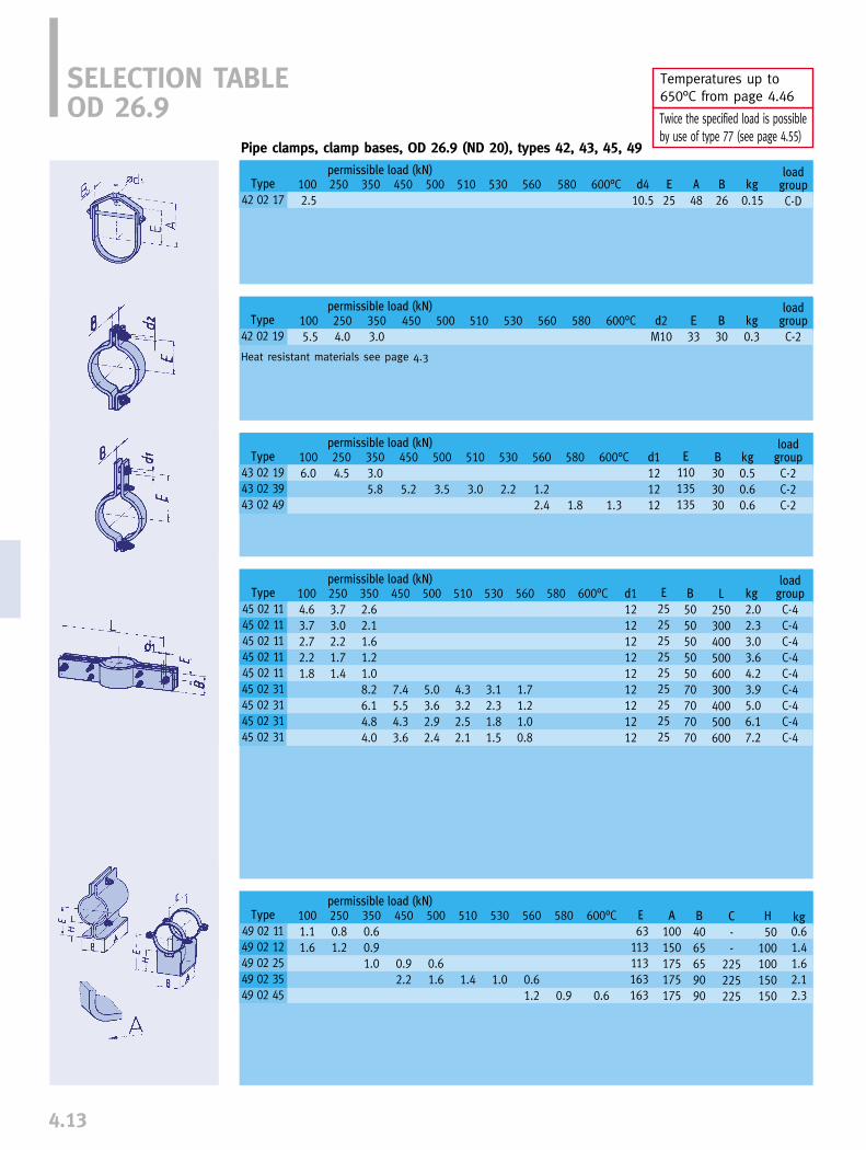
4.13
Temperatures up to 650°C from page 4.46
Twice the specified load is possible by use of type 77 (see page 4.55)
Pipe clamps, clamp bases, OD 26.9 (ND 20), types 42, 43, 45, 49
SELECTION TABLEOD 26.9
Type
42 02 19
loadgroup
C-2
permissible load (kN)1005.5
2504.0
3503.0
450 500 530 600°C d2M10
B
30kg
0.3510 E
33
Type
43 02 1943 02 3943 02 49
loadgroup
C-2C-2C-2
permissible load (kN)1006.0
2504.5
3503.05.8
450
5.2
500
3.5
530
2.2
600°C
1.3
d1121212
B
303030
kg
0.50.60.6
510
3.0
E
110135135
Type
45 02 1145 02 1145 02 1145 02 1145 02 1145 02 3145 02 3145 02 3145 02 31
loadgroup
C-4C-4C-4C-4C-4C-4C-4C-4C-4
permissible load (kN)1004.63.72.72.21.8
2503.73.02.21.71.4
3502.62.11.61.21.08.26.14.84.0
450
7.45.54.33.6
500
5.03.62.92.4
530
3.12.31.81.5
600°C d1121212121212121212
B
505050505070707070
kg
2.02.33.03.64.23.95.06.17.2
510
4.33.22.52.1
E
252525252525252525
L
250300400500600300400500600
Type
49 02 1149 02 1249 02 2549 02 3549 02 45
permissible load (kN)1001.11.6
2500.81.2
3500.60.91.0
450
0.92.2
500
0.61.6
530
1.0
600°C
0.6
A
100150175175175
B
4065659090
kg0.61.41.62.12.3
510
1.4
E
63113113163163
C
--
225225225
H
50100100150150
Heat resistant materials see page 4.3
Type
42 02 17
loadgroup
C-D
permissible load (kN)1002.5
250 350 450 500 530 560 E
25B
26kg
0.15510 580 600°C d4
10.5
560 580
560
1.22.4
580
1.8
560
1.71.21.00.8
580
560
0.61.2
580
0.9
A
48

4.14
4Temperatures up to 650°C from page 4.46
Twice the specified load is possible by use of type 77 (see page 4.55)
SELECTION TABLEOD 33.7
Type
42 03 19
loadgroup
C-2
permissible load (kN)1005.5
2504.0
3503.0
450 500 530 600°C d2M10
B
30kg
0.4510 E
36
Type
43 03 1943 03 3943 03 49
loadgroup
C-2C-2C-2
permissible load (kN)1006.0
2504.5
3503.05.8
450
5.2
500
3.5
530
2.2
600°C
1.6
d1121212
B
303040
kg
0.60.81.1
510
3.0
E
120165165
permissible load (kN)1005.84.73.42.62.2
2504.63.82.72.21.8
Type
49 03 1149 03 1249 03 2549 03 3549 03 45
permissible load (kN)1001.11.6
2500.81.2
3500.60.91.2
450
1.02.5
500
0.71.9
530
1.2
600°C
0.7
A
100150175175175
B
4570
100100100
kg
0.71.52.32.32.5
510
1.6
E
67117167167167
C
--
225225225
H
50100150150150
3503.32.72.01.51.38.59.66.29.64.99.64.09.6
450
7.78.15.68.14.48.13.68.1
500
5.17.83.77.82.97.82.47.8
loadgroup
C-4C-4C-4C-4C-4C-4C-4C-4C-4C-4C-4C-4C-4
530
3.27.62.37.61.87.61.57.6
600°C d112121212121212121212121212
B
60606060607090709070907090
kg
2.42.83.54.35.03.9
10.15.0
12.96.1
15.77.2
18.6
510
4.57.73.37.72.67.72.17.7
E
25252525252525252525252525
L
250300400500600300300400400500500600600
Heat resistant materials see page 4.3
Pipe clamps, clamp bases, OD 33.7 (ND 25), types 42, 43, 45, 49
Type
45 03 1145 03 1145 03 1145 03 1145 03 1145 03 3145 03 3245 03 3145 03 3245 03 3145 03 3245 03 3145 03 32
Type
42 03 17
loadgroup
C-D
permissible load (kN)1002.5
250 350 450 500 530 560 E
32B
26kg
0.16510 580 600°C d4
10.5
560 580
560
1.22.8
580
2.1
560
1.77.41.36.51.05.10.84.2
580
560
0.71.4
580
1.1
A
54
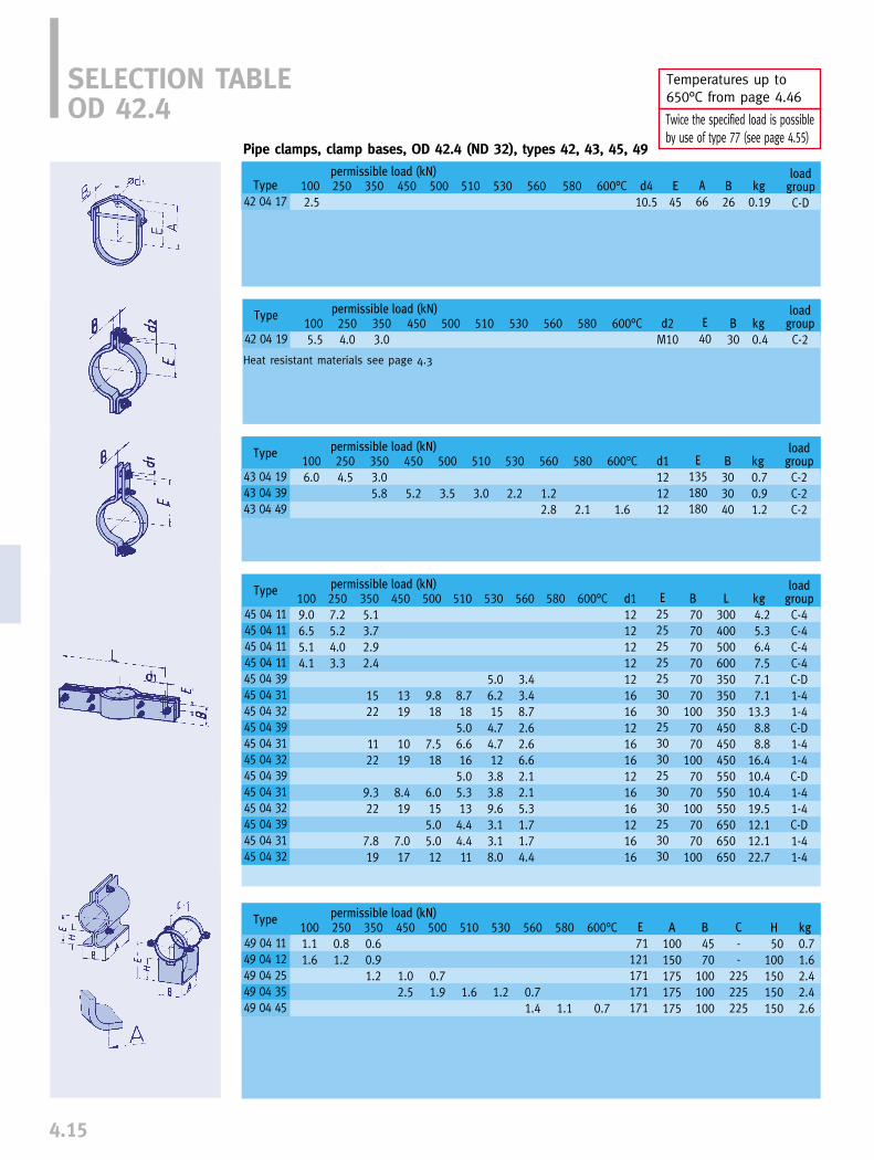
4.15
Temperatures up to 650°C from page 4.46
Twice the specified load is possible by use of type 77 (see page 4.55)
SELECTION TABLEOD 42.4
Type
42 04 19
loadgroup
C-2
permissible load (kN)1005.5
2504.0
3503.0
450 500 530 600°C d2M10
B
30kg
0.4510 E
40
Type
43 04 1943 04 3943 04 49
loadgroup
C-2C-2C-2
permissible load (kN)1006.0
2504.5
3503.05.8
450
5.2
500
3.5
530
2.2
600°C
1.6
d1121212
B
303040
kg
0.70.91.2
510
3.0
E
135180180
permissible load (kN)1009.06.55.14.1
2507.25.24.03.3
Type
49 04 1149 04 1249 04 2549 04 3549 04 45
permissible load (kN)1001.11.6
2500.81.2
3500.60.91.2
450
1.02.5
500
0.71.9
530
1.2
600°C
0.7
A
100150175175175
B
4570
100100100
kg
0.71.62.42.42.6
510
1.6
E
71121171171171
C
--
225225225
H
50100150150150
Type
45 04 1145 04 1145 04 1145 04 1145 04 3945 04 3145 04 3245 04 3945 04 3145 04 3245 04 3945 04 3145 04 3245 04 3945 04 3145 04 32
3505.13.72.92.4
1522
1122
9.322
7.819
450
1319
1019
8.419
7.017
500
9.818
7.518
6.0155.05.012
loadgroup
C-4C-4C-4C-4C-D1-41-4C-D1-41-4C-D1-41-4C-D1-41-4
530
5.06.2154.74.7123.83.89.63.13.18.0
600°C d112121212121616121616121616121616
B
707070707070
1007070
1007070
1007070
100
kg
4.25.36.47.57.17.1
13.38.88.8
16.410.410.419.512.112.122.7
510
8.7185.06.6165.05.3134.44.411
E
25252525253030253030253030253030
L
300400500600350350350450450450550550550650650650
Heat resistant materials see page 4.3
Pipe clamps, clamp bases, OD 42.4 (ND 32), types 42, 43, 45, 49
Type
42 04 17
loadgroup
C-D
permissible load (kN)1002.5
250 350 450 500 530 560 E
45B
26kg
0.19510 A
66580 600°C d4
10.5
560 580
560
1.22.8
580
2.1
560
3.43.48.72.62.66.62.12.15.31.71.74.4
580
560
0.71.4
580
1.1
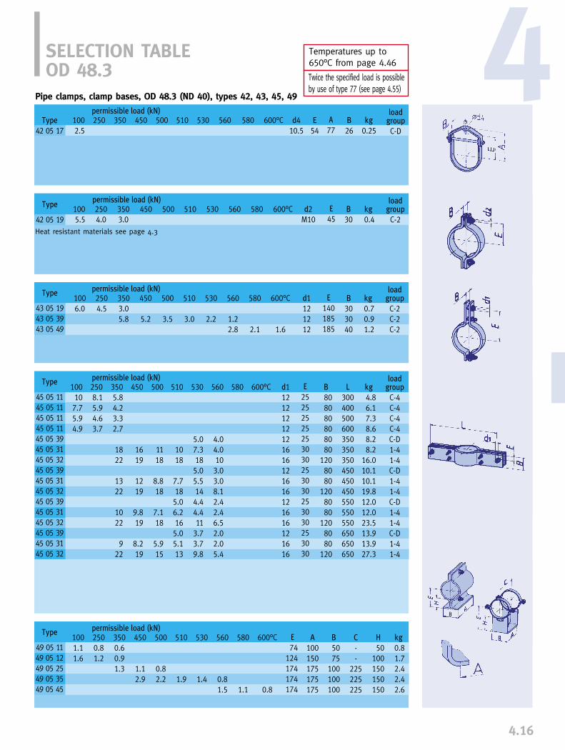
4.16
4Temperatures up to 650°C from page 4.46
Twice the specified load is possible by use of type 77 (see page 4.55)
SELECTION TABLEOD 48.3
Type
42 05 19
loadgroup
C-2
permissible load (kN)1005.5
2504.0
3503.0
450 500 530 600°C d2M10
B
30kg
0.4510 E
45
Type
43 05 1943 05 3943 05 49
loadgroup
C-2C-2C-2
permissible load (kN)1006.0
2504.5
3503.05.8
450
5.2
500
3.5
530
2.2
600°C
1.6
d1121212
B
303040
kg
0.70.91.2
510
3.0
E
140185185
permissible load (kN)100107.75.94.9
2508.15.94.63.7
Type
49 05 1149 05 1249 05 2549 05 3549 05 45
permissible load (kN)1001.11.6
2500.81.2
3500.60.91.3
450
1.12.9
500
0.82.2
530
1.4
600°C
0.8
A
100150175175175
B
5075
100100100
kg
0.81.72.42.42.6
510
1.9
E
74124174174174
C
--
225225225
H
50100150150150
Type
45 05 1145 05 1145 05 1145 05 1145 05 3945 05 3145 05 3245 05 3945 05 3145 05 3245 05 3945 05 3145 05 3245 05 3945 05 3145 05 32
3505.84.23.32.7
1822
1322
1022
922
600°C
Heat resistant materials see page 4.3
Pipe clamps, clamp bases, OD 48.3 (ND 40), types 42, 43, 45, 49
Type
42 05 17
loadgroup
C-D
permissible load (kN)1002.5
250 350 450 500 530 560 E
54B
26kg
0.25510 A
77580 600°C d4
10.5
560 580
560
1.22.8
580
2.1
580450
1619
1219
9.819
8.219
500
1118
8.818
7.118
5.915
510
1018
7.7185.06.2165.05.113
530
5.07.3185.05.5144.44.411
3.73.79.8
560
4.04.0103.03.08.12.42.46.52.02.05.4
d112121212121616121616121616121616
E
25252525253030253030253030253030
B
808080808080
1208080
1208080
1208080
120
L
300400500600350350350450450450550550550650650650
kg
4.86.17.38.68.28.2
16.010.110.119.812.012.023.513.913.927.3
loadgroup
C-4C-4C-4C-4C-D1-41-4C-D1-41-4C-D1-41-4C-D1-41-4
560
0.81.5
580
1.1
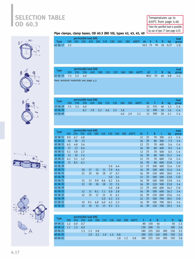
4.17
Temperatures up to 650°C from page 4.46
Twice the specified load is possible by use of type 77 (see page 4.55)
SELECTION TABLEOD 60.3
Type
42 06 19
loadgroup
C-2
permissible load (kN)1007.5
2505.5
3504.0
450 500 530 600°C d2M12
B
40kg
0.8510 E
55
Type
43 06 1943 06 3943 06 49
loadgroup
C-4C-4C-4
permissible load (kN)1007.5
2505.5
3504.08.7
450
7.9
500
5.2
530
3.3
600°C
2.2
d1121212
B
405050
kg
1.21.62.1
510
4.6
E
155200200
permissible load (kN)1009.0246.5175.1134.111
2506.7184.8133.8103.18.5
Type
49 06 1149 06 1249 06 2549 06 3549 06 45
permissible load (kN)1001.21.7
2500.91.3
3500.70.91.3
450
1.12.9
500
0.82.2
530
1.4
600°C
0.8
A
150200225225225
B
5075
110110110
kg
1.32.43.53.53.8
510
1.9
E
80130180180180
C
--
285285285
H
50100150150150
Type
45 06 1145 06 1245 06 1145 06 1245 06 1145 06 1245 06 1145 06 1245 06 3945 06 3145 06 3245 06 3945 06 3145 06 3245 06 3945 06 3145 06 3245 06 3945 06 3145 06 32
loadgroup
C-41-4C-41-4C-41-4C-41-4C-D1-41-4C-D1-41-4C-D1-41-4C-D1-41-4
600°C B
7080708070807080
100100120100100120100100120100100120
kg
4.37.35.49.26.5
11.17.6
13.011.411.418.013.813.821.816.216.225.618.518.529.3
510
1118
8.618
7.1155.06.013
E
2530253025302530253030253030253030253030
L
300300400400500500600600400400400500500500600600600700700700
530
5.07.9175.06.2135.05.011
4.34.39.3
Heat resistant materials see page 4.3
Pipe clamps, clamp bases, OD 60.3 (ND 50), types 42, 43, 45, 49
Type
42 06 17
loadgroup
C-D
permissible load (kN)1002.5
250 350 450 500 530 560 E
75B
26kg
0.27510 A
94580 600°C d4
10.5
560 580
560
1.84.0
580
2.9
560
4.44.49.73.43.47.52.82.86.12.32.35.1
5803504.8133.49.42.77.42.26.1
2022
1522
1222
1022
450
1719
1319
1119
9.519
500
1218
9.918
8.117
6.815
d11216121612161216121616121616121616121616
560
0.81.8
580
1.2
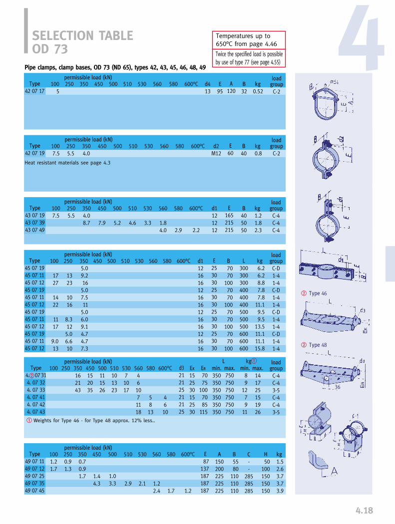
4.18
4
� Type 46
� Type 48
Temperatures up to 650°C from page 4.46
Twice the specified load is possible by use of type 77 (see page 4.55)
36
SELECTION TABLEOD 73
Type
42 07 19
loadgroup
C-2
permissible load (kN)1007.5
2505.5
3504.0
450 500 530 600°C d2M12
B
40kg
0.8510
Type
43 07 1943 07 3943 07 49
loadgroup
C-4C-4C-4
permissible load (kN)1007.5
2505.5
3504.08.7
450
7.9
500
5.2
530
3.3
600°C
2.2
d1121212
B
405050
kg
1.21.82.3
510
4.6
E
165215215
permissible load (kN)
permissible load (kN)
Type
45 07 1945 07 1145 07 1245 07 1945 07 1145 07 1245 07 1945 07 1145 07 1245 07 1945 07 1145 07 12
450 500 600°C510 E
253030253030253030253030
530
permissible load (kN)1001.21.7
2500.91.3
3500.70.91.7
450
1.44.3
500
1.03.3
530
2.1
600°C
1.2
510
2.9
L kg�
Heat resistant materials see page 4.3
Type
49 07 1149 07 1249 07 2549 07 3549 07 45
Pipe clamps, clamp bases, OD 73 (ND 65), types 42, 43, 45, 46, 48, 49
Type
42 07 17
loadgroup
C-2
permissible load (kN)100
5250 350 450 500 530 560 E
95B
32kg
0.52510 A
120580 600°C d4
13
560 580 E
60
560
1.84.0
580
2.9
560 580100
1727
1422
1117
9.013
250
1323
1016
8.3125.06.610
3505.09.2165.07.511
5.06.09.14.74.77.3
d1121616121616121616121616
B
7070
1007070
1007070
1007070
100
L
300300300400400400500500500600600600
kg
6.26.28.87.87.8
11.19.59.5
13.511.111.115.8
loadgroup
C-D1-41-4C-D1-41-4C-D1-41-4C-D1-41-4
100 250 500111526
53071017
EK
152530152530
ER
7075
1007085
115
510101323
min.350350350350350350
max.
750750750750750750
min.
89
1279
11
max.
141725151926
Type
4.�07314. 07 324. 07 334. 07 414. 07 424. 07 43
350162143
450152035
600°C
4610
d3212125212125
560461071118
580
5813
loadgroup
C-4C-43-5C-4C-43-5
580
1.7
560
1.22.4
E
87137187187187
A
150200225225225
B
5580
110110110
C
--
285285285
H
50100150150150
kg
1.52.63.73.73.9
� Weights for Type 46 - for Type 48 approx. 12% less..

4.19
Temperatures up to 650°C from page 4.46
Twice the specified load is possible by use of type 77 (see page 4.55)
� Type 46
� Type 48
36
SELECTION TABLEOD 76.1
permissible load (kN)100 250 350
162143
450152035
500111526
53071017
600°C
4610
510101323
loadgroup
C-4C-43-5C-4C-43-5
L kg�
Type
42 08 19
loadgroup
C-2
permissible load (kN)1007.5
2505.5
3504.0
450 500 530 600°C d2M12
B
40kg
0.9510
Type
43 08 1943 08 3943 08 49
permissible load (kN)1007.5
2505.5
3504.08.7
450
7.9
500
5.2
530
3.3
510
4.6
permissible load (kN)Type
45 08 1945 08 1145 08 1245 08 1945 08 1145 08 1245 08 1945 08 1145 08 1245 08 1945 08 1145 08 12
450 500 600°C510 530
permissible load (kN)
Heat resistant materials see page 4.3
Type
4.�08314. 08 324. 08 334. 08 414. 08 424. 08 43
Pipe clamps, clamp bases, OD 76.1 (ND 65), types 42, 43, 45, 46, 48, 49
Type
42 08 17
loadgroup
C-2
permissible load (kN)100
5250 350 450 500 530 560 E
95B
32kg
0.54510 A
120580 600°C d4
13
E
60560 580
560
1.84.0
580
2.9
600°C
2.2
d1121212
E
165215215
B
405050
kg
1.21.82.3
loadgroup
C-4C-4C-4
560 580100
1727
1422
1117
9.013
250
1323
1016
8.3125.06.610
3505.09.2165.07.511
5.06.09.14.74.77.3
d1121616121616121616121616
E
253030253030253030253030
B
7070
1007070
1007070
1007070
100
L
300300300400400400500500500600600600
kg
6.66.69.38.28.2
11.69.99.9
14.011.511.516.3
loadgroup
C-D1-41-4C-D1-41-4C-D1-41-4C-D1-41-4
580
5813
d3212125212125
EK
152530152530
ER
7075
1007085
115
min.
350350350350350350
max.
750750750750750750
min.
8101479
13
max.
141725151927
1001.21.7
2500.91.3
3500.70.91.7
450
1.44.3
500
1.03.3
530
2.1
600°C
1.2
A
150200225225225
B
5580
110110110
kg
1.52.63.73.74.0
510
2.9
E
88138188188188
C
--
285285285
H
50100150150150
Type
49 08 1149 08 1249 08 2549 08 3549 08 45
560
1.22.4
580
1.7
560461071118
� Weights for Type 46 - for Type 48 approx. 14% less.

4.20
4Temperatures up to 650°C from page 4.46
Twice the specified load is possible by use of type 77 (see page 4.55)
� Type 46
� Type 48
36
SELECTION TABLEOD 88.9
permissible load (kN)
permissible load (kN)
permissible load (kN)
permissible load (kN)
permissible load (kN)
L kg�
Heat resistant materials see page 4.3
Pipe clamps, clamp bases, OD 88.9 (ND 80), types 42, 43, 45, 46, 48, 49
Type
42 09 17
loadgroup
C-2
permissible load (kN)1005.0
250 350 450 500 530 560 E
100B
32kg
0.60510 A
121580 600°C d4
13
Type
42 09 19
loadgroup
C-21006.5
2504.5
3503.5
450 500 530 600°C d2M12
B
40kg
1.0510 E
70560 580
Type
43 09 1843 09 1943 09 3843 09 3943 09 49
loadgroup
C-D1-4C-D1-4C-4
100
7.5
250
5.5
3502.54.0
8.7
450
7.9
500
5.2
530
2.53.3
600°C
2.2
d11216121612
B
4040505050
kg
1.41.41.91.92.5
510
4.6
E
170170235235235
560
1.81.84.0
580
2.9
Type
45 09 1945 09 1145 09 1245 09 1945 09 1145 09 1245 09 1945 09 1145 09 1245 09 1945 09 1145 09 12
450 500load
group
C-D1-41-4C-D1-41-4C-D1-41-4C-D1-41-4
600°C510 530 560 580100
1727
1219
9.013
7.110
250
1323
8.914
6.6105.05.27.9
3505.09.5165.06.4105.04.77.33.73.75.6
d1121616121616121616121616
E
253030253030253030253030
B
7070
1007070
1007070
1007070
100
L
300300300450450450600600600750750750
kg
6.76.79.49.19.1
12.911.611.616.514.114.120.0
Type
4.� 09314. 09 324. 09 334. 09 414. 09 424. 09 43
100 250 350162143
450152035
500111526
53071017
600°C
4610
EK
152535152535
ER
7585
10075
100105
510101323
d3212125212125
min.
350350350350350350
max.
850850850850850850
min.
99
1389
12
max.
192532182435
loadgroup
C-4C-43-5C-4C-43-5
560461071119
580
5813
1001.82.5
2501.41.9
3501.01.32.3
450
1.95.2
500
1.43.9
530
2.5
600°C
1.5
A
150200275275275
B
6085
145145145
kg
2.33.85.45.65.7
510
3.4
E
94144244244244
C
--
335335335
H
50100200200200
Type
49 09 1149 09 1249 09 2549 09 3549 09 45
560
1.52.9
580
2.2
� Weights for Type 46 - for Type 48 approx. 15% less.
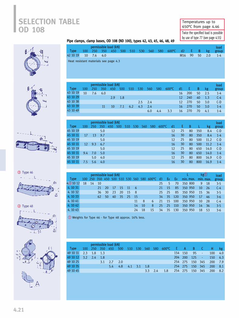
4.21
� Type 46
� Type 48
51
Temperatures up to 650°C from page 4.46
Twice the specified load is possible by use of type 77 (see page 4.55)
Pipe clamps, clamp bases, OD 108 (ND 100), types 42, 43, 45, 46, 48, 49
SELECTION TABLEOD 108
Type
42 10 19
loadgroup
1-4
permissible load (kN)10010
2507.6
3506.0
450 500 530 560 580 600°C d2M16
B
50kg
2.0510 E
90
Type43 10 1943 10 2943 10 3843 10 3943 10 49
loadgroup
1-4C-4C-D1-41-4
permissible load (kN)10010
2507.6
3506.0
11
450
2.9
10
500
1.8
7.1
530
2.54.3
560
2.42.46.0
580
4.4
600°C
3.3
d11612121616
B
5040505070
kg
2.51.33.03.04.1
510
6.2
E
200240270270270
permissible load (kN)
permissible load (kN)10018
25014
35010213662
450
203050
500
172340
530
111525
580
81018
600°C
68
15
510
152035
max.
800950950950950950950
Type
45 10 1945 10 1145 10 1945 10 1145 10 1945 10 1145 10 1945 10 11
450 500 600°C510 530 560 580
Type
49 10 1149 10 1249 10 2549 10 35 49 10 45
permissible load (kN)1002.33.2
2501.82.4
3501.31.83.1
450
2.75.4
500
2.04.8
530
3.1
560
1.83.3
580
2.4
600°C
1.8
A
150200275275275
B
95125150150150
kg
4.06.37.98.18.2
510
4.1
E
154204254254254
C
--
345345345
H
100150200200200
min.
9101517101418
max.
18263646283653
loadgroup
3-5C-43-53-6C-43-53-6
L kg�
Heat resistant materials see page 4.3
100
17
12
9.4
7.5
250
13
9.3
7.05.05.6
3505.09.75.06.75.05.04.04.0
d11216121612161216
E
2530253025302530
B
8080808080808080
L
350350500500650650800800
kg
8.48.4
11.211.214.014.016.916.9
loadgroup
C-D1-4C-D1-4C-D1-4C-D1-4
Type
4.�10 124. 10 314. 10 324. 10 334. 10 414. 10 424. 10 43
560
6815111424
d325212534212534
EK
5152535152535
ER
708585
120100110130
min.
350350350350350350350
� Weights for Type 46 - for Type 48 approx. 16% less.
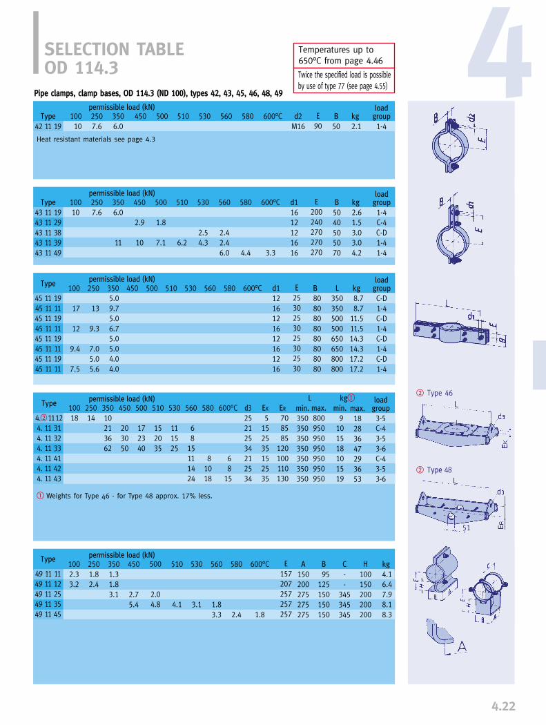
4.22
4
� Type 46
� Type 48
Temperatures up to 650°C from page 4.46
Twice the specified load is possible by use of type 77 (see page 4.55)
51
SELECTION TABLEOD 114.3
Type
42 11 19
permissible load (kN)
loadgroup
1-4C-4C-D1-41-4
permissible load (kN)10010
2507.6
3506.0
11
450
2.9
10
500
1.8
7.1
530
2.54.3
560
2.42.46.0
580
4.4
600°C
3.3
d11612121616
B
5040505070
kg
2.61.53.03.04.2
510
6.2
E
200240270270270
permissible load (kN)450 500 600°C510 530 560 580
Type
49 11 1149 11 1249 11 2549 11 3549 11 45
permissible load (kN)1002.33.2
2501.82.4
3501.31.83.1
450
2.75.4
500
2.04.8
530
3.1
560
1.83.3
580
2.4
600°C
1.8
A
150200275275275
B
95125150150150
kg
4.16.47.98.18.3
510
4.1
E
157207257257257
C
--
345345345
H
100150200200200
loadgroup
1-410010
2507.6
3506.0
450 500 530 560 580 600°C d2M16
B
50kg
2.1510 E
90
Heat resistant materials see page 4.3
Pipe clamps, clamp bases, OD 114.3 (ND 100), types 42, 43, 45, 46, 48, 49
Type
43 11 1943 11 2943 11 3843 11 3943 11 49
Type
45 11 1945 11 1145 11 1945 11 1145 11 1945 11 1145 11 1945 11 11
100
17
12
9.4
7.5
250
13
9.3
7.05.05.6
3505.09.75.06.75.05.04.04.0
d11216121612161216
E
2530253025302530
B
8080808080808080
L
350350500500650650800800
kg
8.78.7
11.511.514.314.317.217.2
loadgroup
C-D1-4C-D1-4C-D1-4C-D1-4
� Weights for Type 46 - for Type 48 approx. 17% less.
Type
4.� 11124. 11 314. 11 324. 11 334. 11 414. 11 424. 11 43
permissible load (kN)10018
25014
35010213662
450
203050
500
172340
530
111525
560
68
15111424
580
81018
ER
708585
120100110130
510
152035
d325212534212534
min.
350350350350350350350
max.
800950950950950950950
min.
9101518101519
max.
18283647293653
loadgroup
3-5C-43-53-6C-43-53-6
L kg�600°C
68
15
EK
5152535152535

4.23
� Type 46
� Type 48
51
Temperatures up to 650°C from page 4.46
Twice the specified load is possible by use of type 77 (see page 4.55)
SELECTION TABLEOD 133
Type
49 13 1149 13 1249 13 2549 13 3549 13 45
permissible load (kN)1002.53.8
2502.03.0
3501.42.04.5
450
3.78.6
500
2.76.5
530
4.2
560
2.44.4
580
3.3
600°C
2.4
A150200275275275
B105130160160160
kg5.38.39.69.89.7
510
5.7
E
167217267267267
C--
350350350
H100150200200200
Type
42 13 19
permissible load (kN) loadgroup
1-410010
2507.6
3505.6
450 500 530 560 580 600°C d2M16
B
50kg
2.2510 E
100
Heat resistant materials see page 4.3
Pipe clamps, clamp bases, OD 133 (ND 125), types 42, 43, 45, 46, 48, 49
loadgroup
1-4C-D1-4C-D1-41-4
permissible load (kN)10010
2507.6
3506.0
12
450
4.6
11
500
2.52.8
7.5
530
4.7
580
4.4
600°C
3.3
d1161216121616
B
505050606070
kg
2.82.32.33.93.95.6
510
6.5
E
220270270290290290
Type
43 13 1943 13 2843 13 2943 13 3843 13 3943 13 49
permissible load (kN)450 500 600°C510 530 560 580Type
45 13 1945 13 1145 13 1945 13 1145 13 1945 13 1145 13 1945 13 11
100
18
13
9.9
8.0
250
14
9.7
7.45.05.9
3505.0105.06.95.05.34.24.2
d11216121612161216
E
2530253025302530
B
9090909090909090
L
400400550550700700850850
kg
10.710.713.913.917.117.120.220.2
loadgroup
C-D1-4C-D1-4C-D1-4C-D1-4
560
2.52.66.0
� Weights for Type 46 - for Type 48 approx. 18% less.
Type
4.� 13124. 13 314. 13 324. 13 334. 13 414. 13 424. 13 43
permissible load (kN)10022
25018
35013233765
450
203555
500
202645
530
121729
560
71017121831
580
91323
ER
7095
100130105115145
510
172340
d325212534212534
min.
400400400400400400400
max.
850100010001000100010001000
min.
12131726131826
max.
22354257344567
loadgroup
3-5C-43-54-6C-43-54-6
L kg�600°C
71017
EK
10153040153040

4.24
4
� Type 46
� Type 48
Temperatures up to 650°C from page 4.46
Twice the specified load is possible by use of type 77 (see page 4.55)
51
SELECTION TABLEOD 139.7
Pipe clamps, clamp bases, OD 139.7 (ND 125), types 42, 43, 45, 46, 48, 49
Type
42 14 19
permissible load (kN) loadgroup
1-410010
2507.4
3505.3
450 500 530 560 580 600°C d2M16
B
50kg
2.4510 E
105
Heat resistant materials see page 4.3
loadgroup
1-4C-D1-4C-D1-41-4
permissible load (kN)10010
2507.6
3506.0
12
450
4.6
11
500
2.52.8
7.5
530
4.7
580
4.4
600°C
3.3
d1161216121616
B
505050606070
kg
2.92.52.54.14.15.7
510
6.5
Type
43 14 1943 14 2843 14 2943 14 3843 14 3943 14 49
560
2.52.66.0
E
225275275295295295
permissible load (kN)450 500 600°C510 530 560 580
Type
45 14 1945 14 1145 14 1945 14 1145 14 1945 14 1145 14 1945 14 11
100
18
13
9.9
8.0
250
14
9.7
7.45.05.9
3505.0105.06.95.05.34.24.2
d11216121612161216
E
2530253025302530
B
9090909090909090
L
400400550550700700850850
kg
11.111.114.314.317.517.520.620.6
loadgroup
C-D1-4C-D1-4C-D1-4C-D1-4
� Weights for Type 46 - for Type 48 approx. 19% less.
Type
4.� 14124. 14 314. 14 324. 14 334. 14 414. 14 424. 14 43
permissible load (kN)10022
25017
35012233765
450
203555
500
202645
530
121729
560
71017121831
580
91323
ER
7095
100130105115145
510
172340
d325212534212534
min.
400400400400400400400
max.
850100010001000100010001000
min.
11132024142026
max.
24354157354766
loadgroup
3-5C-43-54-6C-43-54-6
L kg�600°C
71017
EK
10153040153040
Type
49 14 1149 14 1249 14 2549 14 3549 14 45
permissible load (kN)1002.53.8
2502.03.0
3501.42.04.5
450
3.78.6
500
2.76.5
530
4.2
560
2.44.4
580
3.3
600°C
2.4
A150200275275275
B105130160160160
kg5.58.59.79.89.8
510
5.7
E
170220270270270
C--
350350350
H100150200200200
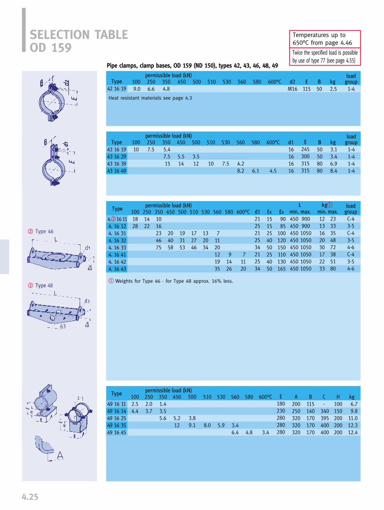
4.25
� Type 46
� Type 48
63
Temperatures up to 650°C from page 4.46
Twice the specified load is possible by use of type 77 (see page 4.55)
SELECTION TABLEOD 159
Pipe clamps, clamp bases, OD 159 (ND 150), types 42, 43, 46, 48, 49
Type
42 16 19
permissible load (kN) loadgroup
1-41009.0
2506.6
3504.8
450 500 530 560 580 600°C d2M16
B
50kg
2.5510 E
115
Heat resistant materials see page 4.3
loadgroup
1-41-41-41-4
permissible load (kN)10010
2507.5
3505.47.515
450
5.514
500
3.512
530
7.5
580
6.1
600°C
4.5
d116161616
B
50508080
kg
3.13.46.98.4
510
10
Type
43 16 1943 16 2943 16 3943 16 49
560
4.28.2
E
245300315315
� Weights for Type 46 - for Type 48 approx. 16% less.
permissible load (kN)1001828
2501422
450
204058
500
193153
530
132034
ER
9085
100120150110130165
510
172746
min.
450450450450450450450450
max.
900900105010501050105010501050
min.
1213162030172233
max.
2333354872385180
L kg�
Type
49 16 1149 16 1449 16 2549 16 3549 16 45
permissible load (kN)1002.54.4
2502.03.7
3501.43.55.6
450
5.212
500
3.89.1
530
5.9
560
3.46.4
580
4.8
600°C
3.4
A200250320320320
B115140170170170
kg6.79.8
11.012.312.4
510
8.0
E
180230280280280
C-
340395400400
H100150200200200
d32125212534212534
EK
1515254050254050
loadgroup
C-43-5C-43-54-6C-43-54-6
560
71120121935
580
91426
600°C
71120
Type
4.� 16114. 16 124. 16 314. 16 324. 16 334. 16 414. 16 424. 16 43
3501016234675
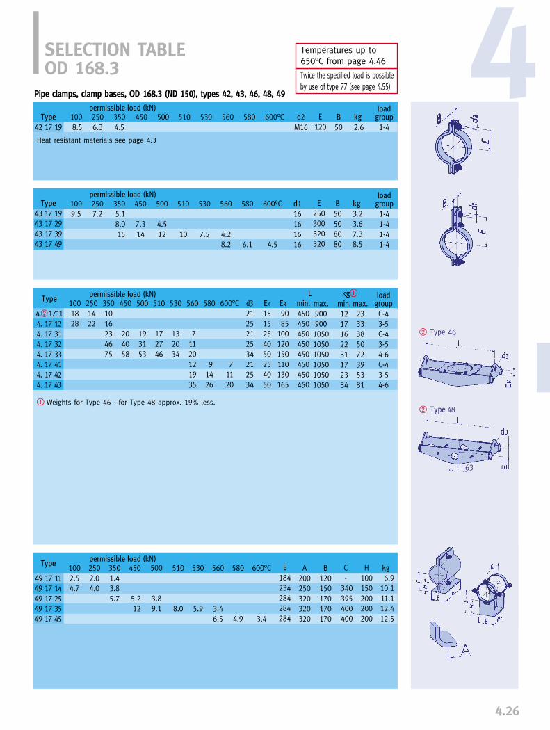
4.26
4
� Type 46
� Type 48
Temperatures up to 650°C from page 4.46
Twice the specified load is possible by use of type 77 (see page 4.55)
63
SELECTION TABLEOD 168.3
Pipe clamps, clamp bases, OD 168.3 (ND 150), types 42, 43, 46, 48, 49
Type
42 17 19
permissible load (kN) loadgroup
1-41008.5
2506.3
3504.5
450 500 530 560 580 600°C d2M16
B
50kg
2.6510 E
120
Heat resistant materials see page 4.3
loadgroup
1-41-41-41-4
permissible load (kN)1009.5
2507.2
3505.18.015
450
7.314
500
4.512
530
7.5
580
6.1
600°C
4.5
d116161616
B
50508080
kg
3.23.67.38.5
510
10
Type
43 17 1943 17 2943 17 3943 17 49
560
4.28.2
E
250300320320
� Weights for Type 46 - for Type 48 approx. 19% less.
permissible load (kN)1001828
2501422
450
204058
500
193153
530
132034
ER
9085
100120150110130165
510
172746
min.
450450450450450450450450
max.
900900105010501050105010501050
min.
1217162231172334
max.
2333385072395381
L kg�
Type
49 17 1149 17 1449 17 2549 17 3549 17 45
permissible load (kN)1002.54.7
2502.04.0
3501.43.85.7
450
5.212
500
3.89.1
530
5.9
560
3.46.5
580
4.9
600°C
3.4
A200250320320320
B120150170170170
kg6.9
10.111.112.412.5
510
8.0
E
184234284284284
C-
340395400400
H100150200200200
d32125212534212534
EK
1515254050254050
loadgroup
C-43-5C-43-54-6C-43-54-6
560
71120121935
580
91426
600°C
71120
Type
4.� 17114. 17 124. 17 314. 17 324. 17 334. 17 414. 17 424. 17 43
3501016234675
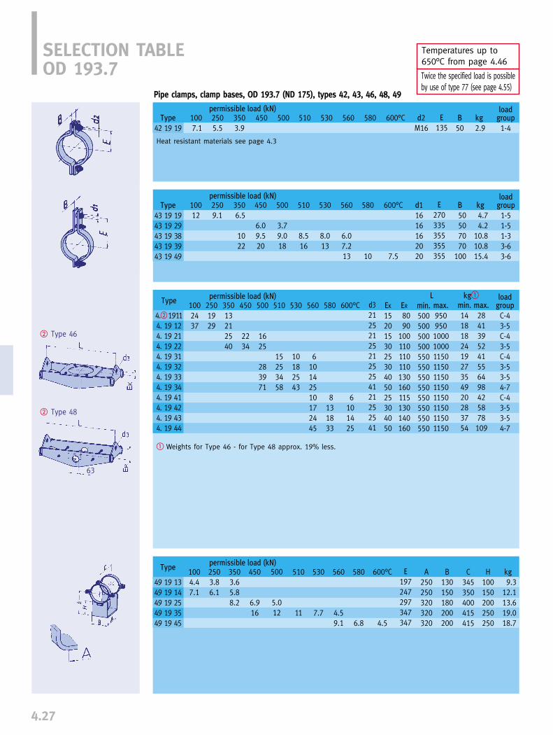
4.27
� Type 46
� Type 48
63
Temperatures up to 650°C from page 4.46
Twice the specified load is possible by use of type 77 (see page 4.55)
SELECTION TABLEOD 193.7
Pipe clamps, clamp bases, OD 193.7 (ND 175), types 42, 43, 46, 48, 49
Type
42 19 19
permissible load (kN) loadgroup
1-41007.1
2505.5
3503.9
450 500 530 560 580 600°C d2M16
B
50kg
2.9510 E
135
Heat resistant materials see page 4.3
loadgroup
1-51-51-33-63-6
permissible load (kN)10012
2509.1
3506.5
1022
450
6.09.520
500
3.79.018
530
8.013
580
10
600°C
7.5
d11616162020
B
50507070
100
kg
4.74.2
10.810.815.4
510
8.516
Type
43 19 1943 19 2943 19 3843 19 3943 19 49
560
6.07.213
E
270335355355355
� Weights for Type 46 - for Type 48 approx. 19% less.
permissible load (kN)1002437
2501929
450
2234
500
1625
283971
530
10182543
ER
8090
100110110110130160115130140160
510
15253458
min.
500500500500550550550550550550550550
max.
9509501000100011501150115011501150115011501150
min.
141818241927354920283754
max.
2841395241556498425878109
L kg�
Type
49 19 1349 19 1449 19 2549 19 3549 19 45
permissible load (kN)1004.47.1
2503.86.1
3503.65.88.2
450
6.916
500
5.012
530
7.7
560
4.59.1
580
6.8
600°C
4.5
A250250320320320
B130150180200200
kg9.3
12.113.619.018.7
510
11
E
197247297347347
C345350400415415
H100150200250250
d3212521252125254121252541
EK
152015302530405025304050
loadgroup
C-43-5C-43-5C-43-53-54-7C-43-53-54-7
560
610142510172445
580
8131833
600°C
6101425
Type
4.� 19114. 19 124. 19 214. 19 224. 19 314. 19 324. 19 334. 19 344. 19 414. 19 424. 19 434. 19 44
35013212540
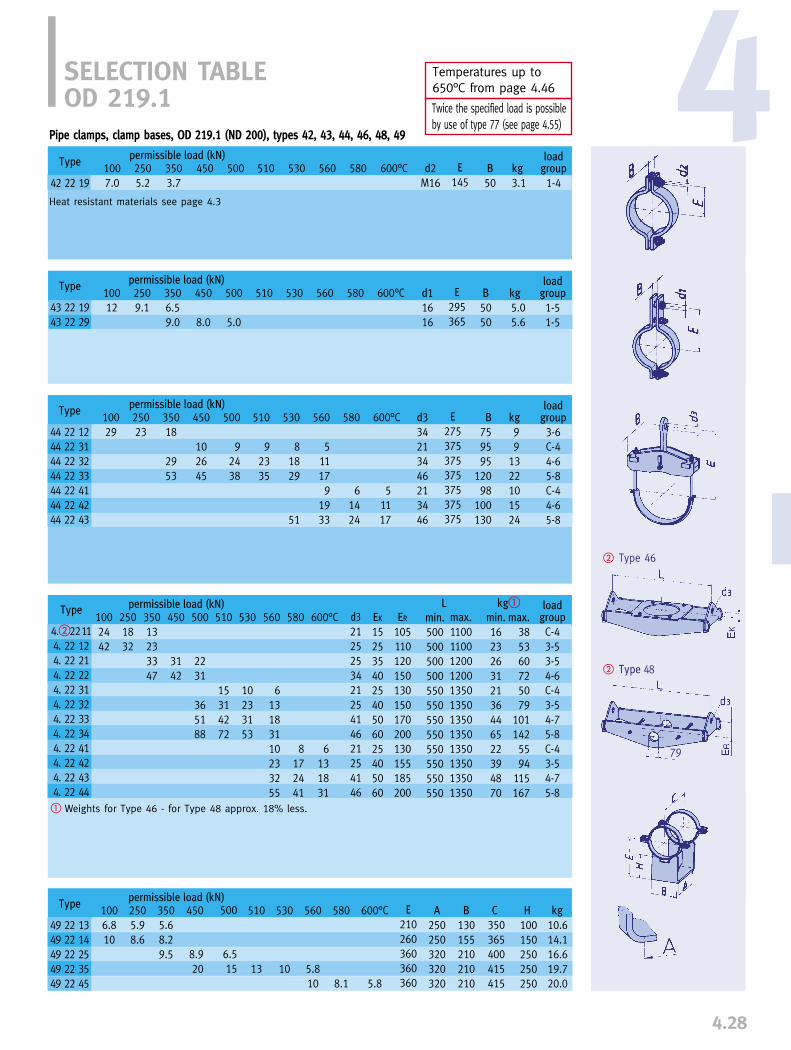
4.28
4
� Type 46
� Type 48
Temperatures up to 650°C from page 4.46
Twice the specified load is possible by use of type 77 (see page 4.55)
79
SELECTION TABLEOD 219.1
permissible load (kN)1002442
2501832
35013233347
450
3142
500
2231
365188
530
10233153
510
15314272
L kg�
Heat resistant materials see page 4.3
loadgroup
1-4
permissible load (kN)1007.0
2505.2
3503.7
450 500 530 600°C d2M16
B
50kg
3.1510 E
145
Type
43 22 1943 22 29
loadgroup
1-51-5
permissible load (kN)10012
2509.1
3506.59.0
450
8.0
500
5.0
530 600°C d11616
B
5050
kg
5.05.6
510 E
295365
permissible load (kN)1006.810
2505.98.6
3505.68.29.5
450
8.920
500
6.515
530
10
600°C
5.8
A
250250320320320
B
130155210210210
kg
10.614.116.619.720.0
510
13
E
210260360360360
C
350365400415415
H
100150250250250
loadgroup
3-6C-44-65-8C-44-65-8
permissible load (kN)10029
25023
35018
2953
450
102645
500
92438
530
81829
51
600°C
51117
d334213446213446
B
759595
12098
100130
kg
99
1322101524
510
92335
E
275375375375375375375
Pipe clamps, clamp bases, OD 219.1 (ND 200), types 42, 43, 44, 46, 48, 49
560 580Type
42 22 19
560 580
560
511179
1933
580
61424
Type
44 22 1244 22 3144 22 3244 22 3344 22 4144 22 4244 22 43
Type
4.�22114. 22 124. 22 214. 22 224. 22 314. 22 324. 22 334. 22 344. 22 414. 22 424. 22 434. 22 44
580
8172441
560
613183110233255
600°C
6131831
d3212525342125414621254146
EK
152535402540506025405060
ER
105110120150130150170200130155185200
min.
500500500500550550550550550550550550
max.
110011001200120013501350135013501350135013501350
min.
162326312136446522394870
max.
385360725079
1011425594
115167
loadgroup
C-43-53-54-6C-43-54-75-8C-43-54-75-8
560
5.810
580
8.1
Type
49 22 1349 22 1449 22 2549 22 3549 22 45
� Weights for Type 46 - for Type 48 approx. 18% less.

4.29
64
� Type 46
� Type 48
79
Temperatures up to 650°C from page 4.46
Twice the specified load is possible by use of type 77 (see page 4.55)
Type
42 24 19
SELECTION TABLEOD 244.5
Heat resistant materials see page 4.3
loadgroup1-4
1006.3
2504.7
3503.4
450 500 530 600°C d2M16
B50
kg3.3
510 E160
Type
43 24 1943 24 29
loadgroup1-51-5
permissible load (kN)10012
25011
3508.49.0
450
8.0
500
5.0
530 600°C d11616
B5050
kg6.15.8
510 E310390
permissible load (kN)1003050
2502340
35017283853
450
3445
500
2434
405696
530
12243458
510
17344680
permissible load (kN)1007.011
2506.09.7
3505.69.213
450
1227
530
13
510
18
L kg�
permissible load (kN)
Pipe clamps. clamp bases, OD 244.5 (ND 225), types 42, 43, 44, 46, 48, 49
permissible load (kN)560 580
560 580
1002038
2501635
3501229
3052
450
9.52645
500
9.02438
510
8.52335
530
81829
51
560
511179
1833
580
61424
600°C
51117
d33446213446213446
E300330390390390390390390
B75809595
12098
100130
kg912101423111625
loadgroup3-65-8C-44-65-8C-44-65-8
Type
4.�24114. 24 124. 24 214. 24 224. 24 314. 24 324. 24 334. 24 344. 24 414. 24 424. 24 434. 24 44
560
714203412253661
600°C
7142034
580
9182746
d3253425342525414625254146
EK
253540453045506030455060
ER
100120130150110150160180120150160190
min.500500550550550550550550550550550550
max.110011001200120013501350135013501350135013501350
min.202730392540517326435478
max.466066775985
11115561
101125180
loadgroup3-54-63-54-63-53-54-75-83-53-54-75-8
Type
49 24 1349 24 1449 24 2549 24 3549 24 45
560
7.515
580
11
600°C
7.5
E222272372372372
A250250320320320
B130170220220220
C350365410420420
H100150250250250
kg11.115.520.524.224.6
Type
44 24 1244 24 1344 24 3144 24 3244 24 3344 24 4144 24 4244 24 43
� Weights for type 46 - for type 48 approx. 22% less.
500
8.520
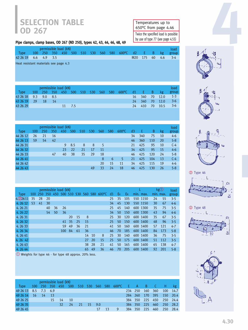
4.30
4
80
� Type 46
� Type 48
Temperatures up to 650°C from page 4.46
Twice the specified load is possible by use of type 77 (see page 4.55)
92
SELECTION TABLEOD 267
permissible load (kN)1003553
2502841
35020304054
450
3650
500
2636
4159
100
530
15253661
600°C
8152136
EK
354545503050507030505070
ER
105130140150120150160185140175165205
510
20354984
d3253425342525414625254146
min.550550600600600600600600600600600600
max.115011501300130014001400140014001400140014001400
min.243035433548578436516592
max.556775946796
12117375
112138201
loadgroup3-54-63-54-63-53-54-75-83-53-54-75-8
L kg�
Heat resistant materials see page 4.3
loadgroup3-4
permissible load (kN)1006.6
2504.9
3503.5
450 500 530 600°C d2M20
B60
kg4.6
510 E175
loadgroup1-33-63-6
permissible load (kN)1009.329
2509.018
3508.514
450
11
500
7.5
530 600°C d1162424
B707070
kg12.012.010.5
510 E340340410
permissible load (kN)
loadgroup4-65-8C-44-65-8C-44-65-8
permissible load (kN)1002659
2502154
3501642
47
450
92340
500
8.52238
530
81729
49
600°C
51118
d33446213446213446
kg1020101524131926
510
82135
E340360425425425425425425
B75
1109595
120104115130
Type43 26 1843 26 1943 26 29
Pipe clamps, clamp bases, OD 267 (ND 250), types 42, 43, 44, 46, 48, 49
560 580Type42 26 19
560 580
560
511188
2033
580
61524
Type44 26 1244 26 1344 26 3144 26 3244 26 3344 26 4144 26 4244 26 43
560
815213614273865
580
10202849
Type4.�26114. 26 124. 26 214. 26 224. 26 314. 26 324. 26 334. 26 344. 26 414. 26 424. 26 434. 26 44
1008.516
2507.314
3506.91315
450
1432
500
1024
530
15
600°C
9
A250260350350350
B160170225225225
kg14.720.424.428.228.4
510
21
E234284384384384
C360395450460460
H100150250250250
Type49 26 1349 26 1449 26 2549 26 3549 26 45
560
9.017
580
13
� Weights for type 46 - for type 48 approx. 20% less.

4.31
80
� Type 46
� Type 48
92
Temperatures up to 650°C from page 4.46
Twice the specified load is possible by use of type 77 (see page 4.55)
SELECTION TABLEOD 273
loadgroup3-4
permissible load (kN)1006.4
2504.7
3503.4
450 500 530 600°C d2M20
B60
kg4.7
510 E180
loadgroup1-33-63-6
permissible load (kN)1009.329
2509.018
3508.514
450
13
500
8.8
530 600°C d1162424
B707070
kg12.512.511.0
510 E340340415
permissible load (kN)
permissible load (kN)1008.516
2507.314
3506.91315
450
1432
500
1024
530
15
510
21
L kg�
loadgroup4-65-8C-44-65-8C-44-65-8
permissible load (kN)1002659
2502154
3501642
48
450
92540
500
8.52338
530
81829
49
600°C
51118
d33446213446213446
kg1020101625131927
510
8.52235
E340360425425425425425425
B75
1109595
120104115130
Heat resistant materials see page 4.3
Pipe clamps, clamp bases, OD 273 (ND 250), types 42, 43, 44, 46, 48, 49
Type43 27 1843 27 1943 27 29
560 580Type42 27 19
560 580
560
511188
2033
580
61524
Type44 27 1244 27 1344 27 3144 27 3244 27 3344 27 4144 27 4244 27 43
Type4.�27114. 27 124. 27 214. 27 224. 27 314. 27 324. 27 334. 27 344. 27 414. 27 424. 27 434. 27 44
1003553
2502842
35020304154
450
3650
500
2636
4159
100
510
20354984
530
15253661
560
815213614273865
580
10202849
600°C
8152136
d3253425342525414625254146
EK
354545503050507030505070
ER
105130140150120150160185140175165205
min.550550600600600600600600600600600600
max.115011501300130014001400140014001400140014001400
min.273337473648589037526696
max.577076956896
12217576
113139206
loadgroup3-54-63-54-63-53-54-75-83-53-54-75-8
Type49 27 1349 27 1449 27 2549 27 3549 27 45
560
9.017
580
11
600°C
9
E237287387387387
A250260350350350
B160170225225225
C360395450460460
H100150250250250
kg14.820.524.528.328.7
� Weights for type 46 - for type 48 approx. 22% less.
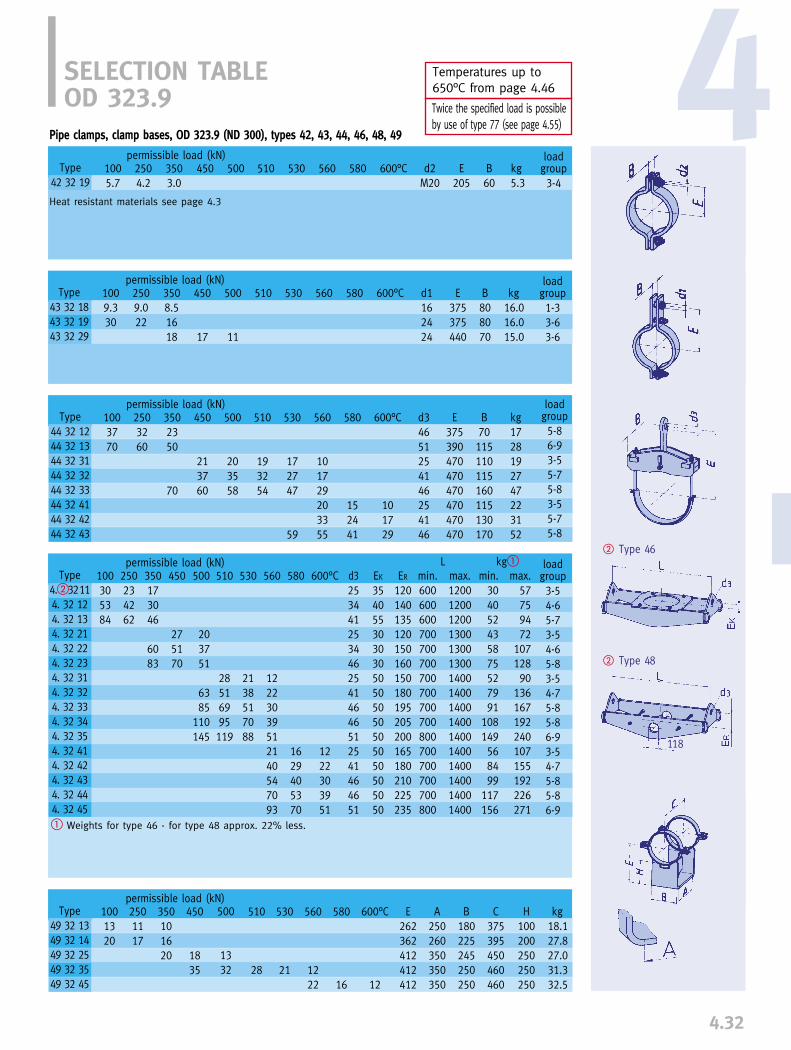
4.32
4
93
� Type 46
� Type 48
Temperatures up to 650°C from page 4.46
Twice the specified load is possible by use of type 77 (see page 4.55)
118
SELECTION TABLEOD 323.9
loadgroup3-4
permissible load (kN)1005.7
2504.2
3503.0
450 500 530 600°C d2M20
B60
kg5.3
510 E205
Heat resistant materials see page 4.3
Type43 32 1843 32 1943 32 29
loadgroup1-33-63-6
permissible load (kN)1009.330
2509.022
3508.51618
450
17
500
11
530 600°C d1162424
B808070
kg16.016.015.0
510 E375375440
permissible load (kN)100305384
250234262
350173046
6083
450
275170
500
203751
6385
110145
530
2138517088
600°C
1222303951
EK
35405530303050505050505050505050
ER
120140135120150160150180195205200165180210225235
510
28516995119
d325344125344625414646512541464651
min.600600600700700700700700700700800700700700700800
max.1200120012001300130013001400140014001400140014001400140014001400
permissible load (kN)1001320
2501117
350101620
450
1835
500
1332
530
21
600°C
12
A250260350350350
B180225245250250
kg18.127.827.031.332.5
510
28
E262362412412412
C375395450460460
H100200250250250
min.304052435875527991
108149568499
117156
max.57759472
10712890
136167192240107155192226271
loadgroup3-54-65-73-54-65-83-54-75-85-86-93-54-75-85-86-9
L kg�
permissible load (kN)
Pipe clamps, clamp bases, OD 323.9 (ND 300), types 42, 43, 44, 46, 48, 49
560 580Type42 32 19
560 580
Type44 32 1244 32 1344 32 3144 32 3244 32 3344 32 4144 32 4244 32 43
1003770
2503260
3502350
70
450
213760
500
203558
510
193254
530
172747
59
560
101729203355
580
152441
600°C
101729
d34651254146254146
E375390470470470470470470
B70115110115160115130170
kg1728192747223152
loadgroup5-86-93-55-75-83-55-75-8
560
12223039512140547093
580
1629405370
Type4.�32114. 32 124. 32 134. 32 214. 32 224. 32 234. 32 314. 32 324. 32 334. 32 344. 32 354. 32 414. 32 424. 32 434. 32 444. 32 45
560
1222
580
16
Type49 32 1349 32 1449 32 2549 32 3549 32 45
� Weights for type 46 - for type 48 approx. 22% less.

4.33
93
� Type 46
� Type 48
118
Temperatures up to 650°C from page 4.46
Twice the specified load is possible by use of type 77 (see page 4.55)
permissible load (kN)100376693
250295073
350213853
7594
450
24336580
Type4.�36114. 36 124. 36 134. 36 214. 36 224. 36 234. 36 244. 36 314. 36 324. 36 334. 36 344. 36 354. 36 414. 36 424. 36 434. 36 444. 36 45
600°C
1014244059
580
1319325480
560
101424405918254372
107
530
17244169
100
510
24325695
135
500
17244759
67113166
d33434462534415125344146512534414651
EK
3540603040404540506060704050606070
ER
120130145115140155160135160180205230155170190240245
min.700700700700700800800700700800800800700700800800800
max.13001300130014001400140014001500150015001500150015001500150015001500
Lmin.
43536738588595526494
1241775668
105137188
max.72
1001207395
13515592
118160228290103130184254339
kg� loadgroup4-64-66-83-54-65-76-93-54-64-75-86-93-54-64-75-86-9
� Weights for type 46 - for type 48 approx. 23% less.
SELECTION TABLEOD 355.6
Heat resistant materials see page 4.3
Type42 36 19
loadgroup3-4
permissible load (kN)1005.3
2503.9
3502.8
450 500 530 600°C d2M20
B60
kg5.7
510 E220
loadgroup1-33-63-6
permissible load (kN)1009.331
2509.023
3508.51622
450
20
500
13
530 600°C d1162424
B909090
kg19.019.020.5
510 E390390470
permissible load (kN)
loadgroup6-86-93-55-75-83-55-75-8
permissible load (kN)1004470
2503860
3502853
70
450
213960
500
203758
530
172847
59
600°C
101729
d34651254146254146
kg2030213149243255
510
193554
E400420485485485485485485
B75115110120160115130170
Pipe clamps, clamp bases, OD 355.6 (ND 350), types 42, 43, 44, 46, 48, 49
Type
43 36 1843 36 1943 36 29
560 580
560 580
560
101729203355
580
152442
Type44 36 1244 36 1344 36 3144 36 3244 36 3344 36 4144 36 4244 36 43
1002227
2501923
350182226
450
2345
500
1741
530
26
600°C
15
A300300400400400
B230235260280280
kg2635344446
510
36
E278378428478478
C440455510525525
H100200250300300
560
1528
580
21
Type49 36 1349 36 1449 36 2549 36 3549 36 45

4.34
4
93
� Type 46
� Type 48
Temperatures up to 650°C from page 4.46
Twice the specified load is possible by use of type 77 (see page 4.55)
118
SELECTION TABLEOD 368
Heat resistant materials see page 4.3
Pipe clamps, clamp bases, OD 368 (ND 350), types 42, 43, 44, 46, 48, 49
loadgroup3-4
permissible load (kN)1005.1
2503.9
3502.8
450 500 530 600°C d2M20
B60
kg5.8
510 E225
loadgroup1-33-63-6
permissible load (kN)1009.330
2509.022
3508.51622
450
20
500
13
530 600°C d1162424
B909090
kg18.518.520.5
510 E395395475
permissible load (kN)100376693
250295072
350213853
7594
450
24336580
500
17244759
69113166
530
17244169
100
600°C
1014244059
EK
3540603040404540506060704050606070
ER
120130145115140155160135160180220230155170190240245
510
24325695
135
d33434462534414625344146512534414651
min.700700700700700800800750750750750850750750750750850
max.13001300130014001400140014001500150015001500150015001500150015001500
permissible load (kN)
min.45556839508097556791
1251845972
101137198
max.73
1001227589
13815793
116163232295105132182258343
loadgroup4-64-66-83-54-65-76-83-54-64-75-86-93-54-64-75-86-9
L kg�
Type43 37 1843 37 1943 37 29
560 580Type42 37 19
560 580
loadgroup6-86-93-55-75-83-55-75-8
permissible load (kN)1004470
2503860
3502753
71
450
213960
500
203758
530
172847
59
600°C
101829
d34651254146254146
kg2031213150243355
510
193554
E400420490490490490490490
B75
115110120160115130170
560
101829203355
580
152442
560
101424405918254372
106
580
1319325480
Type4.�37114. 37 124. 37 134. 37 214. 37 224. 37 234. 37 244. 37 314. 37 324. 37 334. 37 344. 37 354. 37 414. 37 424. 37 434. 37 444. 37 45
1002228
2501924
350182326
450
2446
500
1842
530
27
600°C
16
A300300400400400
B230240260290290
kg2635354648
510
37
E284384434484484
C440455510525525
H100200250300300
Type49 37 1349 37 1449 37 2549 37 3549 37 45
560
1630
580
22
Type44 37 1244 37 1344 37 3144 37 3244 37 3344 37 4144 37 4244 37 43
� Weights for type 46 - for type 48 approx. 23% less.
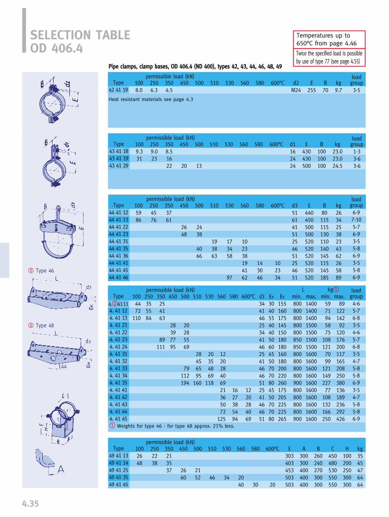
4.35
118
� Type 46
� Type 48
144
Temperatures up to 650°C from page 4.46
Twice the specified load is possible by use of type 77 (see page 4.55)
Type4.�41114. 41 124. 41 134. 41 214. 41 224. 41 234. 41 244. 41 314. 41 324. 41 334. 41 344. 41 354. 41 414. 41 424. 41 434. 41 444. 41 45
SELECTION TABLEOD 406.4
permissible load (kN)1004472
110
250355584
350254163
89111
450
28397795
500
20285569
79112194
530
20354869
118
600°C
1220284069
EK
3040554040506045507070804550707080
ER
155160175145150180180160180200220260175205225225265
510
28456595
160
d33441462534414625414646512541464651
min.800800800800800850850800800800800900800800800800900
max.14001400140015001500150015001600160016001600160016001600160016001600
min.5971945875
1081217099
12114922777
108132166250
max.89
12214292
120176200117165208250380136189236292426
loadgroup4-65-76-83-54-65-76-83-54-75-85-86-93-54-75-85-86-9
L kg�
Heat resistant materials see page 4.3
Pipe clamps, clamp bases, OD 406.4 (ND 400), types 42, 43, 44, 46, 48, 49
Type42 41 19
loadgroup3-5
1008.0
2506.3
3504.5
450 500 530 600°C d2M24
B70
kg9.7
510 E255
loadgroup1-33-63-6
permissible load (kN)1009.331
2509.023
3508.51622
450
20
500
13
530 600°C d1162424
B100100100
kg23.023.024.5
510 E430430500
permissible load (kN)1002648
2502238
350213537
450
2660
500
2152
530
34
510
46
permissible load (kN)1005986
2504576
3503761
450
2648
500
2438
4066
510
193863
Type43 41 1843 41 1943 41 29
permissible load (kN)560 580
560 580
Type44 41 1244 41 1344 41 2244 41 2344 41 3144 41 3544 41 3644 41 4144 41 4544 41 46
560
102338194162
580
143046
600°C
102334
d351614151254651254651
E440450500500520520520520520520
B80115115130110140145115145185
kg26342538234362265889
loadgroup6-97-105-76-93-55-86-93-55-86-9
560
122028406921365072
125
580
1627385494
Type49 41 1349 41 1449 41 2549 41 3549 41 45
560
2040
580
30
600°C
20
E303403453503503
A300300400400400
B260240270300300
C450480530550550
H100200250300300
kg3545476464
� Weights for type 46 - for type 48 approx. 21% less.
530
173458
97

4.36
4
118
� Type 46
� Type 48
Temperatures up to 650°C from page 4.46
Twice the specified load is possible by use of type 77 (see page 4.55)
144
Heat resistant materials see page 4.3
SELECTION TABLEOD 419
permissible load (kN)1004472
110
250355584
350254163
89111
450
28397795
500
20285569
79113194
530
20354869
118
510
28456595
160
L kg�
Pipe clamps, clamp bases, OD 419 (ND 400), types 42, 43, 44, 46, 48, 49
Type
42 42 19
loadgroup3-5
permissible load (kN)1008.0
2506.2
3504.4
450 500 530 600°C d2M24
B70
kg9.7
510 E260
loadgroup1-33-63-6
permissible load (kN)1009.330
2509.023
3508.51622
450
20
500
13
530 600°C d1162424
B100100100
kg232324
510 E435435500
permissible load (kN)
Type
43 42 1843 42 1943 42 29
560 580
560 580
loadgroup6-97-105-76-93-55-86-93-55-86-9
10059150
25045110
3503782
450
2656
500
2450
68
530
173458
98
600°C
102334
d351614151254651254651
kg26602645234363275893
510
194065
E445460500500525525525525525525
B80145115140110140145115145185
Type
44 42 1244 42 1544 42 2244 42 2544 42 3144 42 3544 42 3644 42 4144 42 4544 42 46
560
102439194162
580
143046
permissible load (kN)1003348
2502638
350223537
450
2960
500
2357
510
51
Type
4.�42114. 42 124. 42 134. 42 214. 42 224. 42 234. 42 244. 42 314. 42 324. 42 334. 42 344. 42 354. 42 414. 42 424. 42 434. 42 444. 42 45
560
122028406921365072
125
580
1627385494
600°C
1220284069
d33441462534414625414646512541464651
EK
3040554040506045507070804550707080
ER
155160175145150180180160180200220260175205225225265
min.800800800800800850850800800800900900800800800900900
max.14001400140015001500150015001600160016001600160016001600160016001600
min.5971956076
1051267296
12316023278
107135178255
max.92
12014792
118174204119167205265385138187239296431
loadgroup4-65-76-83-54-65-76-83-54-75-85-86-93-54-75-85-86-9
� Weights for type 46 - for type 48 approx. 21% less.
Type
49 42 1349 42 1449 42 2549 42 3549 42 45
530
38
560
2242
580
32
600°C
22
E310410460510510
A300300400400400
B240240270300300
C420480530550550
H100200250300300
kg3146486565
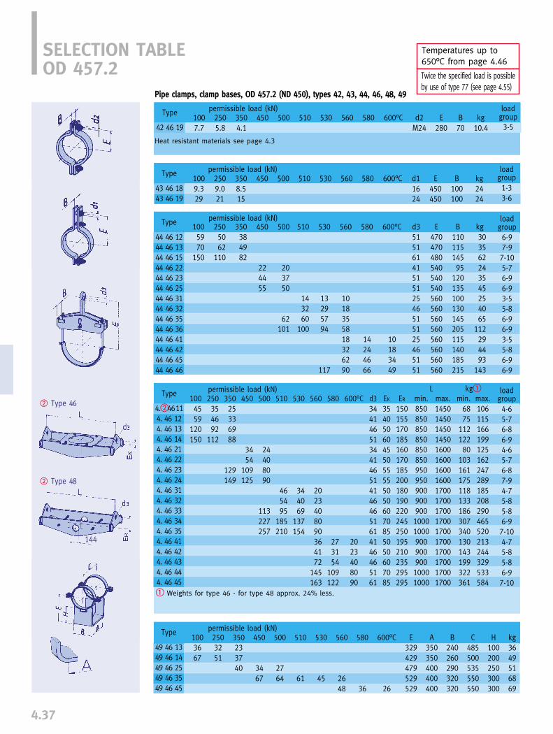
4.37
118
� Type 46
� Type 48
144
Temperatures up to 650°C from page 4.46
Twice the specified load is possible by use of type 77 (see page 4.55)
SELECTION TABLEOD 457.2
Heat resistant materials see page 4.3
Pipe clamps, clamp bases, OD 457.2 (ND 450), types 42, 43, 44, 46, 48, 49
Type
42 46 19
loadgroup3-5
permissible load (kN)1007.7
2505.8
3504.1
450 500 530 600°C d2M24
B70
kg10.4
510 E280
loadgroup1-33-6
permissible load (kN)1009.329
2509.021
3508.515
450 500 530 600°C d11624
B100100
kg2424
510 E450450
permissible load (kN)1004559
120150
250354692
112
35025336988
129149
450
3454
109125
500
24408090
113227257
530
344069
137154
510
465495
185210
permissible load (kN)1003667
2503251
350233740
450
3467
500
2764
530
45
600°C
26
A350350400400400
B240260290320320
kg3649516869
510
61
E329429479529529
C485500535550550
H100200250300300
L kg�
permissible load (kN)
Type
43 46 1843 46 19
560 580
560 580
1005970
150
2505062
110
350384982
450
224455
500
203750
62101
530
13295794
117
510
143260
100
Type
4.�46114. 46 124. 46 134. 46 144. 46 214. 46 224. 46 234. 46 244. 46 314. 46 324. 46 334. 46 344. 46 354. 46 414. 46 424. 46 434. 46 444. 46 45
560
2023408090364172
145163
580
273154
109122
600°C
2023408090
d3344146513441465141464651614146465161
EK
354050604550555550506070855050607085
ER
150155170185160170185200180190220245250195210235295295
min.8508508508508508509509509009009001000100090090090010001000
max.145014501450145016001600160016001700170017001700170017001700170017001700
min.6875
11212280
103161175118133186307340130143199322361
max.106115166199125162247289185208290465520213244329533584
Type
44 46 1244 46 1344 46 1544 46 2244 46 2344 46 2544 46 3144 46 3244 46 3544 46 3644 46 4144 46 4244 46 4544 46 46
560
1018355818326290
580
14244666
600°C
10183449
d35151614151512546515125465151
E470470480540540540560560560560560560560560
B11011514595
120135100130145205115140185215
kg303562243545254065
112294493
143
loadgroup6-97-97-105-76-96-93-55-86-96-93-55-86-96-9
loadgroup4-65-76-86-94-65-76-87-94-75-85-86-97-104-75-85-86-97-10
� Weights for type 46 - for type 48 approx. 24% less.
560
2648
580
36
Type
49 46 1349 46 1449 46 2549 46 3549 46 45
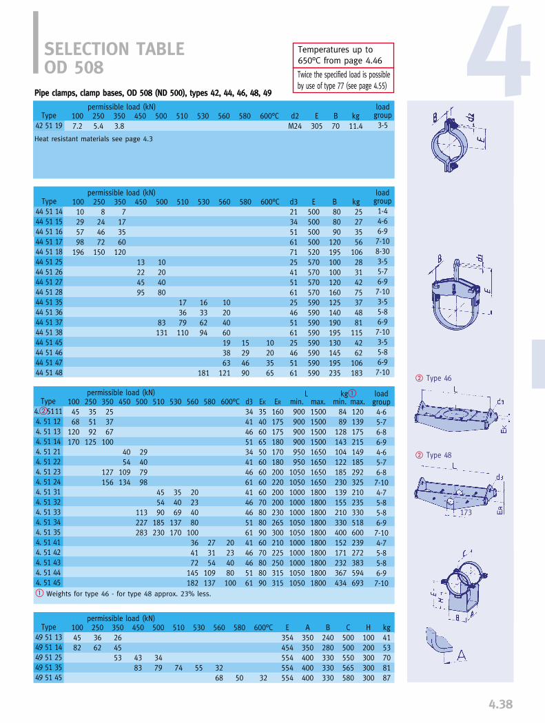
4.38
4
� Type 46
� Type 48
173
Temperatures up to 650°C from page 4.46
Twice the specified load is possible by use of type 77 (see page 4.55)
SELECTION TABLEOD 508
Heat resistant materials see page 4.3
Pipe clamps, clamp bases, OD 508 (ND 500), types 42, 44, 46, 48, 49
Type42 51 19
loadgroup3-5
permissible load (kN)1007.2
2505.4
3503.8
450 500 530 600°C d2M24
B70
kg11.4
510 E305
permissible load (kN)1004568
120170
250355192
125
350253767
100
127156
450
4054
109134
500
29407998
113227283
530
354069
137170
510
455490
185230
permissible load (kN)1004582
2503662
350264553
450
4383
500
3479
530
55
510
74
L kg�
permissible load (kN)10010295798
196
2508
244672
150
3507
173560
120
450
13224595
500
10204080
83131
510
173679110
560 580
Type44 51 1444 51 1544 51 1644 51 1744 51 1844 51 2544 51 2644 51 2744 51 2844 51 3544 51 3644 51 3744 51 3844 51 4544 51 4644 51 4744 51 48
600°C
10203565
560
10204060193863
121
580
15294690
d32134516171254151612546516125465161
E500500500500520570570570570590590590590590590590590
B808090
120195100100120160125140190195130145195235
kg25273556
10628314275374881
1154262
106183
loadgroup1-44-66-97-108-303-55-76-97-103-55-86-97-103-55-86-97-10
Type4.�51114. 51 124. 51 134. 51 144. 51 214. 51 224. 51 234. 51 244. 51 314. 51 324. 51 334. 51 344. 51 354. 51 414. 51 424. 51 434. 51 444. 51 45
560
20234080
100364172
145182
580
273154
109137
600°C
20234080100
d3344146513441466141464651614146465161
EK
354060655060606060708080906070808090
ER
160175175180170180200220200200230265300210225250315315
min.900900900900950950
105010501000100010001050105010001000100010501050
max.150015001500150016501650165016501800180018001800180018001800180018001800
min.8489
128143104122185230139155210330400152171232367434
max.120139175215149185292325210235330518600239272383594693
loadgroup4-65-76-86-94-65-76-87-104-75-85-86-97-104-75-85-86-97-10
Type49 51 1349 51 1449 51 2549 51 3549 51 45
560
3268
580
50
600°C
32
E354454554554554
A350350400400400
B240280330330330
C500500550565580
H100200300300300
kg4153708187
� Weights for type 46 - for type 48 approx. 23% less.
530
16336294
181

4.39
144
� Type 46
� Type 48
173
Temperatures up to 650°C from page 4.46
Twice the specified load is possible by use of type 77 (see page 4.55)
SELECTION TABLEOD 558.8
Heat resistant materials see page 4.3
Pipe clamps, clamp bases, OD 558.8 (ND 550), types 42, 44, 46, 48, 49
Type42 56 19
loadgroup5-6
permissible load (kN)10018
25013
3509.9
450 500 530 600°C d2M30
B90
kg24
510 E350
permissible load (kN)1004568
130207
250345297
153
350253877
122
130194
450
4154
110165
500
304080
120
227342
530
385169
137200
510
537090
185280
permissible load (kN)1005495
2504380
350315863
450
53105
500
42100
510
89
L kg�
permissible load (kN)100204474
100196
25017356077
160
35015264562
120
450
19455390
500
18405080
83120155
510
3679
105150
560 580
Type44 56 1444 56 1544 56 1644 56 1744 56 1844 56 2544 56 2644 56 2744 56 2844 56 3544 56 3644 56 3744 56 3844 56 4544 56 4644 56 4744 56 48
530
336282
130
141200
560
20405580406390127
580
29476694
600°C
20355070
d33446516171345151614651616146516161
E530530530530545600600600600620620620620620620620620
B8590
110120195100120130160135190195215145195205245
kg31354460
106334549785087
11816267
119148206
loadgroup3-65-86-97-108-304-66-96-97-105-86-97-107-105-86-97-107-10
Type4.�56114. 56 124. 56 134. 56 144. 56 214. 56 224. 56 234. 56 244. 56 314. 56 324. 56 334. 56 344. 56 354. 56 414. 56 424. 56 434. 56 444. 56 45
560
22304080
120395472
145217
580
294054109163
600°C
22304080120
d3344151513441515141464651614146465161
EK
405060655560656560607090
10060607090
100
ER
170185195205180190205240200230240270320225220260285360
min.950950950950
10001000110011001100110011001100120011001100110011001200
max.155015501550155017001700170017001900190019001900190019001900190019001900
min.80
100145178116138230278169205241371514187230269415572
max.125153210275167200315395255325365570755291351423660865
loadgroup4-65-76-97-94-65-76-97-94-75-85-86-97-104-75-85-86-97-10
Type49 56 1349 56 1449 56 2549 56 3549 56 45
530
65
600°C
38
A400400450450450
B240290340350350
kg7089102115121
E380480580580580
C570585620635650
H100200300300300
560
3873
580
54
� Weights for type 46 - for type 48 approx. 25% less.

4.40
4
� Type 46
Temperatures up to 650°C from page 4.46
Twice the specified load is possible by use of type 77 (see page 4.55)
� Type 48
199
SELECTION TABLEOD 609.6
Heat resistant materials see page 4.3
Pipe clamps, clamp bases, OD 609.6 (ND 600), types 42, 44, 46, 48, 49
Type42 61 19
loadgroup5-6
permissible load (kN)10017
25013
3509.3
450 500 530 560 d2M30
B90
kg26
510 E375
permissible load (kN)
Type49 61 1349 61 1449 61 2549 61 3549 61 45
permissible load (kN)10062105
2505880
350485865
450
61108
500
48102
530
76
560
4583
A400400450450450
B270310360370370
kg7995107120129
510
98
E455505605605605
C570585620635650
H150200300300300
L kg�
600°C
600°C
45
580
permissible load (kN)100295880
116200
25024456587
165
35020354873
120
450
22426590
500
20385582
115175
510
3878
105160
Type44 61 1444 61 1544 61 1644 61 1744 61 1844 61 2544 61 2644 61 2744 61 2844 61 3544 61 3644 61 3744 61 3844 61 4544 61 4644 61 4744 61 48
560
203960903862
115155
580
294686114
600°C
20346085
d33451516171415161614651617146516171
E560560560560580645645645645685685685685685685685685
B10095
115125195120120140160160190205215160195245245
kg37435065
112434973846198
14018075
118214238
loadgroup3-66-96-97-108-304-76-97-107-105-86-97-108-305-86-97-108-30
1006090
127186223
250476996
138165
350345176
111132
180230
450
57110160200
500
4280
120150
220340420
530
396990
132200260
510
5390
123180280350
Type4.�61114. 61 124. 61 134. 61 144. 61 154. 61 214. 61 224. 61 234. 61 244. 61 314. 61 324. 61 334. 61 344. 61 354. 61 364. 61 414. 61 424. 61 434. 61 444. 61 454. 61 46
560
22405378
120150397296
141217272
580
305472
106163205
600°C
22405378
120150
d3414651516141515161414646516171414646516171
EK
40455055656060607060709090
11011060709090
110110
ER
185195190205230190220235265220235280285325360230275280295355365
min.100010001000100010001100110011001150120012001200130013001300120012001200130013001300
max.160016001600160016001800180018001800200020002000200020002000200020002000200020002000
min.114142166189232161254310382192277326431580691213304368490653774
max.1681852202783202253504705252704004736208309703184665457159601135
loadgroup4-76-86-97-97-104-76-97-98-104-75-85-86-97-108-304-75-85-86-97-108-30
580
62
� Weights for type 46 - for type 48 approx. 26% less.
530
336185
133
152239

4.41
172
� Type 46
� Type 48
224
Temperatures up to 650°C from page 4.46
Twice the specified load is possible by use of type 77 (see page 4.55)
SELECTION TABLEOD 660.4
permissible load (kN)10074120
2506592
350486774
450
66127
500
57120
530
89
600°C
52
A400400450450450
B300330370380380
kg85100112134137
510
115
E480530630630630
C570585620650650
H150200300300300
Pipe clamps, clamp bases, OD 660.4 (ND 650), types 42, 44, 46, 48, 49
loadgroup5-6
permissible load (kN)10016
25012
3508.8
450 500 530 600°C d2M30
B90
kg28
510 E400
permissible load (kN)1006090
135215256
2504670
100155190
350335180
125150
190240
450
63110160200
500
4580
120150
155225340420
530
476992
137200260
510
6090
125185280350
L kg�
permissible load (kN)100355682
128179304
25028446595
135240
35024345378
105180
450
224575
132
500
204070
120
175
510
4083114160
580560Type
42 66 19
Type
44 66 1444 66 1544 66 1644 66 1744 66 1844 66 1944 66 2544 66 2644 66 2744 66 2844 66 3544 66 3644 66 3744 66 3844 66 4544 66 4644 66 4744 66 48
560
204260903977121157
580
295888115
600°C
20426086
d3415151617171415161714651617146516171
E610610610610610635680680680680700700700700700700700700
B10095
120150195215120130155195160195205215160205245245
kg40476577
115170445482
13364
12414518879
157217244
loadgroup4-76-96-97-108-309-304-76-97-108-305-86-97-108-305-86-97-108-30
Type
4.�66114. 66 124. 66 134. 66 144. 66 154. 66 214. 66 224. 66 234. 66 244. 66 314. 66 324. 66 334. 66 344. 66 354. 66 364. 66 414. 66 424. 66 434. 66 444. 66 454. 66 46
560
25405580
120150457299
146218272
580
345475
110164205
600°C
25405580
120150
d3414651616141515161414646516171414646516171
EK
40505560706565708065659090
10011065659090
100110
ER
200215200245235220245260270225245290305315355235285295315350360
min.105010501050105010501250125012501300125012501250125013501350125012501250125013501350
max.165016501650165016501900190019001900205020502050205020502050205020502050205020502050
min.127153180258263196291356415229303363471632748245335405515705835
max.160198255335370269390488585335433532675895
1055366495590775
10201210
loadgroup5-76-86-97-108-104-76-97-98-104-75-85-86-97-108-304-75-85-86-97-108-30
580
72
560
5296
Type49 66 1349 66 1449 66 2549 66 3549 66 45
Heat resistant materialssee page 4.3
530
357086133
158242
� Weights for type 46 - for type 48 approx. 23% less.

4.42
4
� Weights for type 46 - fortype 48 approx. 26% less.
� Type 46
Temperatures up to 650°C from page 4.46
Twice the specified load is possible by use of type 77 (see page 4.55)
� Type 48
224
SELECTION TABLEOD 711.2
Pipe clamps, clamp bases, OD 711.2 (ND 700), types 42, 44, 46, 48, 49
Type42 71 19
loadgroup5-6
permissible load (kN)10015
25011
3508.1
450 500 530 600°C d2M30
B90
kg30
510 E430
permissible load (kN)10074
118180236275
2505790
133175200
3504270
105142160
195240
450
70110170195
500
5080
125156
175225340440
530
4669
105137200270
510
6090
140185280365
permissible load (kN)10085
130
25067
100
350497292
450
82150
500
65142
530
99
510
135
L kg�
permissible load (kN)1004395
124150177307
250367588
120145225
35030607288
115180
450
26436595
131
500
24406080
120
165225
510
4072
105155195
560 580
Type44 71 1444 71 1544 71 1644 71 1744 71 1844 71 1944 71 2544 71 2644 71 2744 71 2844 71 2944 71 3544 71 3644 71 3744 71 3844 71 3944 71 4544 71 4644 71 4744 71 48
560
25406080
1074289
127156
580
316694115
600°C
23476886
d34151617171714151617171465161717146516171
E630630630630630650720720720720720740740740740740740740740740
B105120130165195225120135145160195160190205215255170215255245
kg57718198
12118650628899
14070
10715419525395
179239256
loadgroup4-76-97-108-308-309-305-76-97-108-308-305-86-97-108-309-305-86-97-108-30
Type4.�71114. 71 124. 71 134. 71 144. 71 154. 71 214. 71 224. 71 234. 71 244. 71 314. 71 324. 71 334. 71 344. 71 354. 71 364. 71 414. 71 424. 71 434. 71 444. 71 454. 71 46
560
27406380
1201564972
115145217283
580
375486
109163213
600°C
27406380
120156
d3414651516146515161414651516171414651516171
EK
4555608090707070907070
1001001001307070
100100100130
ER
195240225230215220240250280235250285305335345240290305315355370
min.110011001100110011001250125013501350130013001300140014001450130013001300140014001450
max.170017001700170017002000200020002000210021002100210021002100210021002100210021002100
min.155185235277299232315404491257336450536689856286364497582766944
max.198250339385420315428570650367465645725960
1160411530725825
10901325
loadgroup5-76-87-97-98-105-86-97-98-104-75-86-96-97-108-304-75-86-96-97-108-30
Type49 71 1349 71 1449 71 2549 71 3549 71 45
560
58108
580
81
600°C
58
E506556656656656
A400400450450450
B320350390410410
C570585635650650
H150200300300300
kg90
107130145148
Heat resistant materialssee page 4.3
530
356285
125170
239

4.43
� Weights for type 46 - fortype 48 approx. 24% less.
Heat resistant materialssee page 4.3
� Type 46
� Type 48
250
Temperatures up to 650°C from page 4.46
Twice the specified load is possible by use of type 77 (see page 4.55)
SELECTION TABLEOD 762
Pipe clamps, clamp bases, OD 762 (ND 750), types 42, 44, 46, 48, 49
Type42 76 19
loadgroup5-6
permissible load (kN)10014
25010
3507.7
450 500 530 600°C d2M30
B90
kg31
510 E455
permissible load (kN)10074
120183245310
2505791
135180230
3504269
105140185
200280
450
70110180235
500
5080
130180
225340510
530
5169
100137200290
510
6990
140185280400
permissible load (kN)10095147
25085110
3506280104
450
94171
500
76162
530
120
510
155
L kg�
loadgroup4-76-97-108-308-309-306-97-108-308-309-305-86-97-108-309-305-86-97-108-309-30
permissible load (kN)1005483
115150195307
250426788
115155225
35033537288
120180
220
450
436495
120185
500
406080
100165
235
d3415161717171516171717146516171714651617171
kg707285104130186659111214820184122162217293131187249281372
E670670670670670690760760760760760770770770770770770770770770770
B135120130165195210135145160195215170190205225255195215255255275
510
4072
105160218
530
396495
135180
230335
600°C
27476886
119
560 580
560
26406090
1195090
127158215
580
386693
116159
Type44 76 1444 76 1544 76 1644 76 1744 76 1844 76 1944 76 2544 76 2644 76 2744 76 2844 76 2944 76 3544 76 3644 76 3744 76 3844 76 3944 76 4544 76 4644 76 4744 76 4844 76 49
Type4.�76114. 76 124. 76 134. 76 144. 76 154. 76 214. 76 224. 76 234. 76 244. 76 314. 76 324. 76 334. 76 344. 76 354. 76 364. 76 414. 76 424. 76 434. 76 444. 76 454. 76 46
560
30406080
1201805472
109145219326
580
415482
109163246
600°C
30406080
120180
d3414651516146515161414651516171414651516171
EK
4555658090707080908080
1001001101408080
100100110140
ER
215215245260255250250300300260270310330360400275285335340365430
min.115011501150115011501400140015001500150015001500150015001600150015001500150015001600
max.175017501750175017502200220022002200230023002300230023002300230023002300230023002300
min.170218262308350269372486587326396516601800
1082362430575673887
1198
max.223280353442480380490680780453535705820
10951440500610805945
12401625
loadgroup5-76-87-97-98-105-86-97-98-104-75-86-96-97-108-304-75-86-96-97-108-30
Type49 76 1349 76 1449 76 2549 76 3549 76 45
560
70128
580
96
600°C
70
E531581681681681
A400400450450450
B340370400420420
C590585635650650
H150200300300300
kg104113135152158
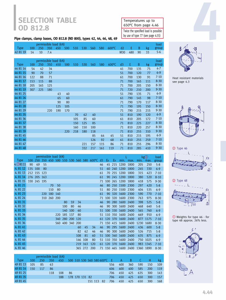
4.44
4
� Weights for type 46 - fortype 48 approx. 26% less.
198
� Type 46
Temperatures up to 650°C from page 4.46
Twice the specified load is possible by use of type 77 (see page 4.55)
� Type 48
250
SELECTION TABLEOD 812.8
Pipe clamps, clamp bases, OD 812.8 (ND 800), types 42, 44, 46, 48, 49
Type42 81 19
loadgroup5-6
permissible load (kN)10014
25010
3507.4
450 500 530 600°C d2M30
B90
kg33
510 E480
permissible load (kN)10090
135212276330
25069
100155205245
3505580
123163195
220310
450
70110180260
500
5080
140200
220340560
530
5980
100137200340
600°C
34466080
120200
EK
45607090
100808090
1009090
1001101201509090
100110120150
ER
215240255245265250250320320280300330350370415295300340350370465
510
80100140185280400
d3465161617146516171464651516171464651516171
min.120012001200120012001500150016001600160016001600160016001600160016001600160016001600
max.180018001800180018002300230023002300240024002400240024002400240024002400240024002400
permissible load (kN)100105150
25085117
3506386118
450
108188
500
86178
530
131
510
170
min.205245315380418297404590763398468565669877
1230436526635750983
1360
max.250330423520575420535770975525640760910
11751680600715875
102513451890
loadgroup5-86-97-108-109-305-86-97-108-305-85-86-96-97-108-305-85-86-96-97-108-30
L kg�
loadgroup4-76-97-108-308-309-306-97-108-308-309-306-97-108-308-309-306-97-108-309-30
permissible load (kN)250427088
115165225
35034577188
125180
220
450
436590
125190
500
406080
105170
220
d34151617171715161717171516171717151617171
kg757791
1111502007198
117150215120172227257310195259296410
E700700700700700720790790790790790810810810810810810810810810
B135120130165205210135145170195215190205225220255215255255285
510
70105150160218
530
6285
125150180
221332
600°C
456886
119
560 580
560
406085
10011885
126157217
580
6492
115161
1005490
122153205307
Type 44 81 1444 81 1544 81 1644 81 1744 81 1844 81 1944 81 2544 81 2644 81 2744 81 2844 81 2944 81 3544 81 3644 81 3744 81 3844 81 3944 81 4544 81 4644 81 4744 81 48
560
34466080
1202006082
108146219365
580
456281
108163272
Type4.�81114. 81 124. 81 134. 81 144. 81 154. 81 214. 81 224. 81 234. 81 244. 81 314. 81 324. 81 334. 81 344. 81 354. 81 364. 81 414. 81 424. 81 434. 81 444. 81 454. 81 46
Type49 81 1349 81 1449 81 2549 81 3549 81 45
560
82151
580
113
600°C
82
E556606706706706
A400400450450450
B360400425425425
C590585635650650
H150200300300300
kg109119143157168
Heat resistant materialssee page 4.3

4.45
� Weights for type 46 - fortype 48 approx. 28% less.
� Type 46
Temperatures up to 650°C from page 4.46
Twice the specified load is possible by use of type 77 (see page 4.55)
� Type 48
279
SELECTION TABLEOD 914.4
Pipe clamps, clamp bases, OD 914.4 (ND 900), types 42, 44, 46, 48, 49
loadgroup5-6
permissible load (kN)10014
25010
3507.7
450 500 530 600°C d2M30
B100
kg40
510 E530
permissible load (kN)10096
135215280335
25071
100155205245
3505780
125165195
210290360
450
80115180250300
500
6085
140200240
400580680
530
69100137235340400
600°C
406080
140200240
EK
50607090
1008090
100100110100110110130130160100110110130130160
ER
255240240265295250270300325345300330350385455440300345370445445490
510
90140185330480550
d346516161714651617171464651617171464651617171
max.1900190019001900190024002400240024002400250025002500250025002500250025002500250025002500
permissible load (kN)
min.245295380448500385490670868936503640775
112014521611551697855
122515921789
max.305365490600670500635855
11151265650835
1030147018702065740945
1160166521052410
loadgroup5-86-97-108-109-305-86-97-108-309-305-85-86-97-108-309-305-85-86-97-108-309-30
L kg�
loadgroup4-76-97-108-308-309-307-98-308-309-309-307-108-309-309-307-108-309-30
permissible load (kN)1005188
153205254307
2504069
115170205225
350335688
125165180
220
450
6590
125140190
500
6080
105130170
195240
d3415161717171517171717161717171617171
kg8288
122166209220106130165220235190245285336290327439
E760760760760760785840840840840840870870870870870870870
B135120165205210210145170195215215205225220255255255285
510
100150185220
530
90130160183
222332
600°C
6886
119
min.1300130013001300130016001600160016001600170017001700170018001800170017001700170018001800
560 580Type
42 91 19
250102163
100130235
35075
132148
450
130250
500
120238
510
227
530
176
560
110210
580
156
600°C
110
E607657757757757
A450450500500500
B360420450480480
C650660710710 710
H150200300300300
kg127148177195210
Type
49 91 1349 91 1449 91 2549 91 3549 91 45
560
6080
103119127158218
580
94115161
Type
44 91 1444 91 1544 91 1644 91 1744 91 1844 91 1944 91 2544 91 2644 91 2744 91 2844 91 2944 91 3544 91 3644 91 3744 91 3844 91 4644 91 4744 91 48
560
406080
14020024072
109146255364438
580
5482
110192272325
Type
4.�91114. 91 124. 91 134. 91 144. 91 154. 91 214. 91 224. 91 234. 91 244. 91 254. 91 314. 91 324. 91 334. 91 344. 91 354. 91 364. 91 414. 91 424. 91 434. 91 444. 91 454. 91 46
Heat resistant materialssee page 4.3

Pipe clamps, OD 33.7 (ND 25), type 43
SELECTION TABLEOD 33.7 - 88.9, TEMPERATURE 610-650°C
Type43 03 59
loadgroupC-2
permissible load (kN)650°C1.8
d112
B50
kg1.4
E235
6103.2
6302.3
Pipe clamps, OD 76.1 (ND 65), types 43, 48
6202.8
6402.1
Type 43
Type 48
4.46
4
Pipe clamps, OD 73 (ND 65), types 43, 48
Type43 07 59
loadgroupC-4
permissible load (kN)650°C2.3
d112
B60
kg2.5
E255
6104.1
6302.9
6203.5
6402.6
Pipe clamps, OD 42.4 (ND 32), type 43
Type43 04 59
loadgroupC-2
permissible load (kN)650°C1.8
d112
B50
kg1.4
E240
6103.2
6302.3
6202.8
6402.1
Pipe clamps, OD 48.3 (ND 40), type 43
Type43 05 59
loadgroupC-2
permissible load (kN)650°C1.8
d112
B50
kg1.4
E240
6103.2
6302.3
6202.8
6402.1
Pipe clamps, OD 60.3 (ND 50), type 43
Type43 06 59
loadgroupC-4
permissible load (kN)650°C2.3
d112
B55
kg2.4
E250
6104.1
6302.9
6203.5
6402.6
Pipe clamps, OD 88.9 (ND 80), types 43, 48
permissible load (kN) L kgType
48 075148 07 5248 07 53
650°C46
10
ER
7070
100
d3212125
min.350350350
max.750750750
min.679
max.131521
loadgroupC-4C-43-5
6107
1017
63058
13
62069
15
64046
11
dN
363636
Type43 08 59
loadgroupC-4
permissible load (kN)650°C2.3
d112
B60
kg2.5
E255
6104.1
6302.9
6203.5
6402.6
permissible load (kN) L kgType
48 085148 08 5248 08 53
650°C46
10
ER
7070
100
d3212125
min.350350350
max.750750750
min.679
max.131521
loadgroupC-4C-43-5
6107
1017
63058
13
62069
15
64046
11
dN
363636
Type43 09 59
loadgroupC-4
permissible load (kN)650°C2.3
d112
B70
kg2.7
E260
6104.1
6302.9
6203.5
6402.6
permissible load (kN) L kgType
48 09 5148 09 5248 09 53
650°C46
10
ER
7585
100
d3212125
min.350350350
max.850850850
min.679
max.161926
loadgroupC-4C-43-5
6107
1017
63057
13
62069
15
64046
11
dN
363636

SELECTION TABLEOD 108 - 159, TEMPERATURE 610 - 650°C
4.47
Pipe clamps, OD 114.3 (ND 100), types 43, 48
Pipe clamps, OD 133 (ND 125), type 43, 48
Pipe clamps, OD 139.7 (ND 125), type 43, 48
Pipe clamps, OD 159 (ND 150), type 43, 48
Type 48
Type 43
Pipe clamps, OD 108 (ND 100), types 43, 48
Type43 10 59
loadgroup1-4
permissible load (kN)650°C5.0
d116
B70
kg5.1
E270
6108.9
6306.3
6207.7
6405.7
permissible load (kN) L kgType
48 105148 10 5248 10 53
650°C68
15
ER
8595
140
d3212534
min.350350350
max.950950950
min.81014
max.242842
loadgroupC-43-53-6
610101327
6308
1021
6209
1223
64069
17
dN
515151
Type43 11 59
loadgroup1-4
permissible load (kN)650°C5.0
d116
B70
kg5.2
E275
6108.9
6306.3
6207.7
6405.7
permissible load (kN) L kgType
48 115148 11 5248 11 53
650°C68
15
ER
8595
140
d3212534
min.350350350
max.950950950
min.81014
max.242842
loadgroupC-43-53-6
610101327
6308
1021
6209
1223
64069
17
dN
515151
Type43 13 59
loadgroup1-4
permissible load (kN)650°C5.6
d116
B80
kg8.1
E290
61010
6307.1
6208.7
6406.5
permissible load (kN) L kgType
48 135148 13 5248 13 53
650°C7
1017
ER
95110150
d3212534
min.400400400
max.100010001000
min.101217
max.273449
loadgroupC-43-54-6
610121729
6309
1322
620101526
6408
1119
dN
515151
Type43 14 59
loadgroup1-4
permissible load (kN)650°C5.6
d116
B80
kg8.2
E295
61010
6307.1
6208.7
6406.5
permissible load (kN) L kgType
48 145148 14 5248 14 53
650°C7
1017
ER
95110150
d3212534
min.400400400
max.100010001000
min.101318
max.283549
loadgroupC-43-54-6
610121729
6309
1322
620101526
6408
1119
dN
515151
Type43 16 59
loadgroup1-4
permissible load (kN)650°C5.6
d116
B80
kg8.8
E315
61010
6307.1
6208.7
6406.5
permissible load (kN) L kgType
48 165148 16 5248 16 53
650°C71120
ER
100125150
d3212534
min.450450450
max.105010501050
min.121623
max.314160
loadgroupC-43-54-6
610121936
6309
1527
620101630
6408
1223
dN
636363

4.48
4Type 43
Type 48
Type 44
SELECTION TABLEOD 168.3 - 244.5, TEMPERATURE 610-650°C
Pipe clamps, OD 168.3 (ND 150), Type 43, 48
Type43 17 59
loadgroup1-4
permissible load (kN)650°C5.6
d116
B80
kg9.1
E320
61010
6307.1
Pipe clamps, OD 193.7 (ND 175), Type 43, 48
Type43 19 59
loadgroup3-6
permissible load (kN)650°C
9d120
B100
kg16
E355
61017
63012
permissible load (kN) L kgType
48 175148 17 5248 17 53
650°C7
1120
dN
636363
ER
100125150
d3212534
min.450450450
max.105010501050
min.121623
max.314260
loadgroupC-43-54-6
610121936
6309
1527
permissible load (kN) L kgType
48 195148 19 5248 19 5348 19 54
650°C6
101425
dN
63636363
ER
110125150160
d321252541
min.550550550550
max.1150115011501150
min.16212538
max.33465682
loadgroupC-43-53-54-7
61010172544
6308
131934
Pipe clamps, OD 219.1 (ND 200), Type 44, 48
permissible load (kN)
permissible load (kN) L kg650°C
6131831
dN
79797979
ER
130150170200
d321254146
min.550550550550
max.1350135013501350
min.18263248
max.517186123
loadgroupC-43-54-75-8
61010233154
6308172441
Type
48 225148 22 5248 22 5348 22 54
Pipe clamps, OD 244.5 (ND 225), Type 44, 48
loadgroupC-44-65-8
permissible load (kN) max max650°C
51117
d3213446
B120105170
ISO280280280
kg233759
E440475500
6108
1930
6306
1422
Type
44 24 5144 24 5244 24 53
permissible load (kN) L kg650°C
7142034
dN
79797979
ER
110150160180
d325254146
min.550550550550
max.1350135013501350
min.20283750
max.567595
130
loadgroup3-53-54-75-8
61012253660
6309
192845
Type
48 245148 24 5248 24 5348 24 54
6208.7
6406.5
620101630
6408
1223
62014
64011
6209
152138
6406
111628
loadgroupC-44-65-8
max max650°C
51117
d3213446
B115105165
ISO280280280
kg213656
E430460485
6108
1930
6306
1422
Type
44 22 5144 22 5244 22 53
6207
1726
6405
1219
6209202746
6407
152035
6207
1726
6405
1219
62011213153
6408
162440
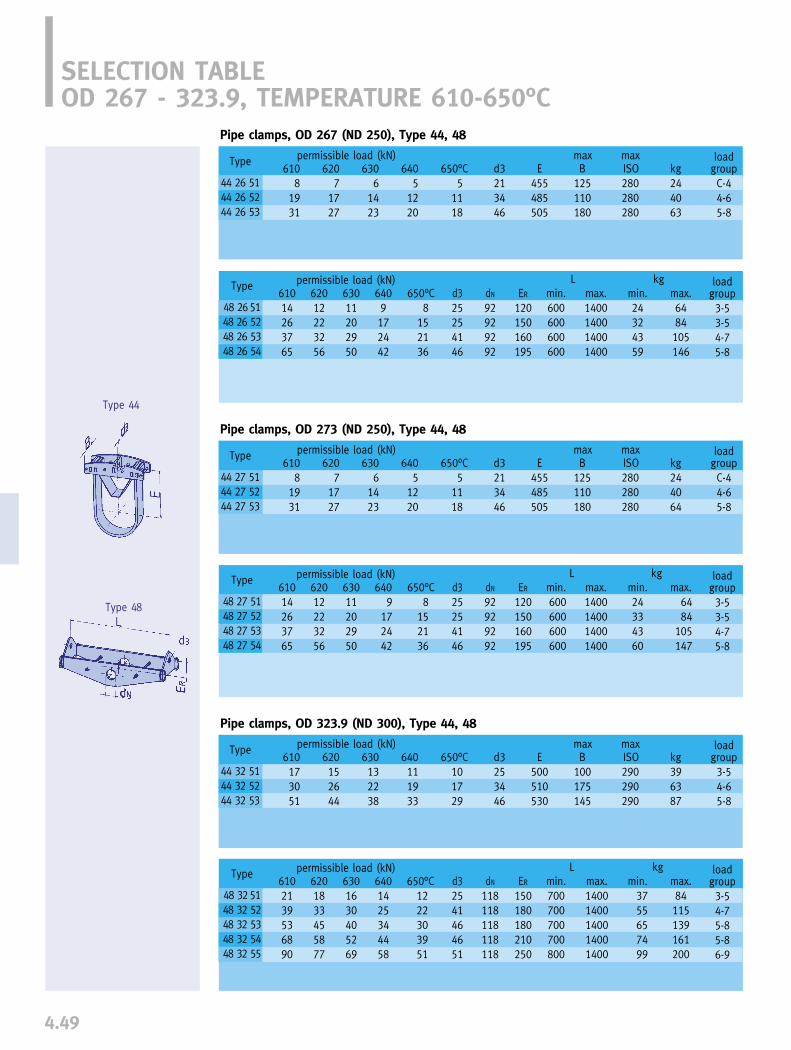
4.49
Type 44
Type 48
SELECTION TABLEOD 267 - 323.9, TEMPERATURE 610-650°C
Pipe clamps, OD 267 (ND 250), Type 44, 48
loadgroupC-44-65-8
permissible load (kN) max max650°C
51118
d3213446
B125110180
ISO280280280
kg244063
E455485505
6108
1931
6306
1423
permissible load (kN) L kg650°C
8152136
dN
92929292
ER
120150160195
d325254146
min.600600600600
max.1400140014001400
min.24324359
max.6484105146
loadgroup3-53-54-75-8
61014263765
63011202950
Pipe clamps, OD 323.9 (ND 300), Type 44, 48
loadgroup3-54-65-8
permissible load (kN) max max650°C
101729
d3253446
B100175145
ISO290290290
kg396387
E500510530
610173051
630132238
Type
44 32 5144 32 5244 32 53
permissible load (kN) L kg650°C
1222303951
dN
118118118118118
ER
150180180210250
d32541464651
min.700700700700800
max.14001400140014001400
min.3755657499
max.84115139161200
loadgroup3-54-75-85-86-9
6102139536890
6301630405269
Pipe clamps, OD 273 (ND 250), Type 44, 48
loadgroupC-44-65-8
permissible load (kN) max max650°C
51118
d3213446
B125110180
ISO280280280
kg244064
E455485505
6108
1931
6306
1423
permissible load (kN) L kg650°C
8152136
dN
92929292
ER
120150160195
d325254146
min.600600600600
max.1400140014001400
min.24334360
max.6484
105147
loadgroup3-53-54-75-8
61014263765
63011202950
Type
48 27 5148 27 5248 27 5348 27 54
Type
44 26 5144 26 5244 26 53
Type
48 265148 26 5248 26 5348 26 54
Type
44 27 5144 27 5244 27 53
Type
48 325148 32 5248 32 5348 32 5448 32 55
6207
1727
6405
1220
62012223256
6409172442
6207
1727
6405
1220
62012223256
6409
172442
620152644
640111933
6201833455877
6401425344458
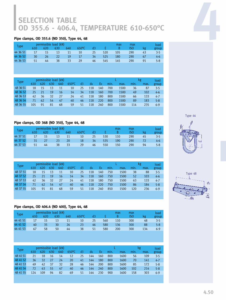
4.50
4
Type 44
Type 48
SELECTION TABLEOD 355.6 - 406.4, TEMPERATURE 610-650°C
Pipe clamps, OD 355.6 (ND 350), Type 44, 48
loadgroup3-54-65-8
permissible load (kN) max max650°C101729
d3253446
B105180145
ISO290290290
kg436791
E520525545
610173051
620152644
630132238
640111933
permissible load (kN) L kg650°C
1014244059
dN
118118118118118
ER
140160180220240
d32534414651
min.700700800800800
max.15001500150015001500
min.36496689
114
max.87
102133183235
loadgroup3-54-64-75-86-9
61018254271
105
6301319325481
Pipe clamps, OD 406.4 (ND 400), Type 44, 48
loadgroup3-55-86-9
permissible load (kN) max max650°C
102338
d3254651
B110136200
ISO300300300
kg4888
134
E560580580
610174067
630133050
Type
44 41 5144 41 5244 41 53
permissible load (kN) L kg650°C
1220284069
dN
144144144144144
ER
160180200240230
d32541464651
min.800800800800900
max.16001600160016001600
min.567085
102158
max.109141172214303
loadgroup3-54-75-85-86-9
61021364972
124
6301627375594
Pipe clamps, OD 368 (ND 350), Type 44, 48
loadgroup3-54-65-8
permissible load (kN) max max650°C
101829
d3253446
B110190150
ISO290290290
kg457294
E530535550
610173151
630132338
permissible load (kN) L kg
Type
44 36 5144 36 5244 36 53
Type
44 37 5144 37 5244 37 53
Type
48 415148 41 5248 41 5348 41 5448 41 55
Type
48 365148 36 5248 36 5348 36 5448 36 55
Type
48 37 5148 37 5248 37 5348 37 5448 37 55
61018254271
105
6301319325481
650°C1014244059
d32534414651
ER
140160180220240
min.750750750750850
max.15001500150015001500
min.38526386
120
max.88
103133184236
loadgroup3-54-64-75-86-9
6201521366291
6401116274768
620152744
640112033
6201521366291
6401116274768
dN
118118118118118
620153558
640112644
62018324263
109
6401424324782

Type 44
Type 48
4.51
Pipe clamps, OD 508 (ND 500), Type 44, 48
SELECTION TABLEOD 419 - 508, TEMPERATURE 610-650°C
Pipe clamps, OD 419 (ND 400), Type 44, 48
loadgroup3-55-86-9
permissible load (kN) max max650°C102439
d3254651
B115136210
ISO300300300
kg5092
140
E565585585
610174269
620153760
630133151
640112745
permissible load (kN) L kg650°C
1220284069
dN
144144144144144
ER
160180200240230
d32541464651
min.800800800900900
max.16001600160016001600
min.577086
111160
max.109142173214305
loadgroup3-54-75-85-86-9
61021364972
124
62018324263
109
6301627375594
6401424324782
loadgroup3-55-86-97-10
permissible load (kN) max maxd325465161
B120136230210
ISO300300300300
kg5995
168226
E615630635650
610173570
106
62015306192
63013265279
64011234669
permissible load (kN) L kgdN
173173173173173
Pipe clamps, OD 457.2 (ND 450), Type 44, 48
permissible load (kN) max max
permissible load (kN) L kg610364170
143160
620313561
126140
630273153
109123
64023264695
106
650°C2023408090
d34146465161
ER
170190230255275
min.90090090010001000
max.17001700170017001700
min.8292
119199215
max.156174237365393
loadgroup4-75-85-86-97-10
Type
44 42 5144 42 5244 42 53
Type
48 42 5148 42 5248 42 5348 42 5448 42 55
610173162
100
62015275486
63013234673
64011204065
650°C10183556
d325465151
E590600605620
B120136195315
ISO300300300300
kg5581
140203
loadgroup3-55-86-96-9
Type
44 46 5144 46 5244 46 5344 46 54
Type
48 46 5148 46 5248 46 5348 46 5448 46 55
650°C10204060
Type
44 51 5144 51 5244 51 5344 51 54
Type
48 51 5148 51 5248 51 5348 51 5448 51 55
610364171
143177
620313661
122156
630273154
109135
64023274692
118
650°C20234080
100
d34146465161
min.10001000100010501050
max.18001800180018001800
min.98
110140228257
max.178197272412469
loadgroup4-75-85-86-97-10
ER
185200235275310
dN
144144144144144

4.52
4
Type 44
Type 48
Pipe clamps, OD 558.8 (ND 550), Type 44, 48
permissible load (kN) max max650°C20406080
d346516161
B136240215290
ISO300300300300
kg104184242305
E655665675690
6103570
106141
620306192
123
630265279
105
64023466993
permissible load (kN) L kgdN
173173173173173
Type
44 56 5144 56 5244 56 5344 56 54
loadgroup5-86-97-107-10
Type
48 56 5148 56 5248 56 5348 56 5448 56 55
610395471
140215
620344763
121186
630304154
107164
64026364791
140
650°C22304080
120
d34146465161
ER
200235240280355
min.11001100110011001200
max.19001900190019001900
min.115141159246337
max.203250296444578
loadgroup4-75-85-86-97-10
Pipe clamps, OD 660.4 (ND 650), Type 44, 48
permissible load (kN) max max650°C20406090
d346516171
B136260230235
ISO310310310310
kg124220285374
E720730745770
6103570
106159
620306192
139
630265279
118
640234669
104
permissible load (kN) L kg
Type
44 66 5144 66 5244 66 5344 66 54
loadgroup5-86-97-108-30
Pipe clamps, OD 609.6 (ND 600), Type 44, 48
loadgroup5-86-97-108-30
permissible load (kN) max maxd346516171
B136255225230
ISO310310310310
kg117206266350
E695705715740
6103570
106159
620306192
139
630265279
118
640234669
104
permissible load (kN) L kg
650°C20406090
Type
44 61 5144 61 5244 61 5344 61 54
Type
48 61 5148 61 5248 61 5348 61 5448 61 5548 61 56
610397393
140213264
620346281
123183233
630305671
107161202
64026476193
138176
650°C22405378
120150
d3414646516171
min.120012001200130013001300
max.200020002000200020002000
min.136193219299382452
max.231334379491631735
loadgroup4-75-85-86-97-108-30
ER
220225280295355350
dN
199199199199199199
SELECTION TABLEOD 558.8 - 660.4, TEMPERATURE 610-650°C
dN
224224224224224224
Type
48 66 5148 66 5248 66 5348 66 5448 66 5548 66 56
610457299
143217267
620396285
126187235
630345575
109166204
64029476495
141177
650°C25405580
120150
d3414646516171
ER
230230280310330350
min.125012501250125013501350
max.205020502050205020502050
min.161217248319420493
max.298362419534679790
loadgroup4-75-85-86-97-108-30

4.53
Type 44
Type 48
SELECTION TABLEOD 711.2 - 812.8, TEMPERATURE 610-650°C
Pipe clamps, OD 762 (ND 750), Type 44, 48
loadgroup5-86-97-108-309-30
permissible load (kN) max maxd34651617171
B175280245250330
ISO310310310310310
kg170258328445585
E770790800815820
6104470
106159211
620386192
139184
630325279
118156
640294669
104138
Pipe clamps, OD 711.2 (ND 700), Type 44, 48
permissible load (kN) max max
permissible load (kN) L kg
630325279
105138
64029466993
121
650°C25406080
105
d34651616171
E740760770785795
B165270240215285
ISO310310310310310
kg155238308345469
loadgroup5-86-97-107-108-30
650°C25406090
119
Type
44 71 5144 71 5244 71 5344 71 5444 71 55
6104470
106141186
620386192
123162
Type
44 76 5144 76 5244 76 5344 76 5444 76 55
Pipe clamps, OD 812.8 (ND 800), Type 44, 48
loadgroup6-97-108-308-309-30
permissible load (kN) max maxd35161717171
B295260245285340
ISO320320320320320
kg282361459514623
E825840850855855
61070
106150177211
6206192
131154184
640466998
116138
6305279
111131156
permissible load (kN) L kgdN
250250250250250250
650°C406085
100119
6106182
107143218361
620537292
123188313
630476382
109166276
64040546993
142236
650°C34466080
120200
d3464651516171
min.160016001600160016001600
max.240024002400240024002400
min.294326396452561783
max.4445026037048791231
ER
280300330350350450
Type
44 81 5144 81 5244 81 5344 81 5444 81 55
loadgroup5-85-86-96-97-108-30
Type
48 81 5148 81 5248 81 5348 81 5448 81 5548 81 56
dN
224224224224224224
6104972
111140217279
620436195
120189246
630375485
106166213
64032467291
142185
650°C27406380
120156
d3414651516171
ER
230230280310335355
min.130013001300140014001450
max.210021002100210021002100
min.176229299350444544
max.318376489554710844
loadgroup4-75-86-96-97-108-30
Type
48 71 5148 71 5248 71 5348 71 5448 71 5548 71 56
permissible load (kN) L kgdN
250250250250250250
6105472
106142215320
620466391
122189283
630415581
108164245
64035476992
143213
650°C30406080
120180
d3414651516171
ER
260260310340330410
min.150015001500150015001600
max.230023002300230023002300
min.251283360411508697
max.3854405606548141068
loadgroup4-75-86-96-97-108-30
Type
48 76 5148 76 5248 76 5348 76 5448 76 5548 76 56

4.54
4Type 44
Type 48
SELECTION TABLEOD 914.4, TEMPERATURE 610-650°C
Pipe clamps, OD 914.4 (ND 900), Type 44, 48
permissible load (kN) max max650°C
406085
100119
d35161717171
B305275255310360
ISO320320320320320
kg326410512593706
E870895905915910
61070
106150177211
6206192
131154184
6305279
111131156
640466998
116138
permissible load (kN) L kg
loadgroup6-97-108-308-309-30
Type
48 91 5148 91 5248 91 5348 91 5448 91 5548 91 56
61071
108143251363429
6206392
122221312378
6305482
108192277328
640477092
167236285
650°C406080
140200240
d3464651617171
ER
300330350385470450
min.170017001700170018001800
max.250025002500250025002500
min.351412506678917
1042
max.523630786
104413461501
loadgroup5-85-86-97-108-309-30
Type
44 91 5144 91 5244 91 5344 91 5444 91 55
dN
279279279279279279
LIFT-OFF RESTRAINT FORCLAMP BASES TYPE 49
Order details:Lift-off restraint Type 49 00 ..
Lift-off restraint for clampbases type 49
Type 49 00 01 to 49 00 04
Afor clamp basesType
49 00 0149 00 0149 00 0149 00 0149 00 0149 00 0249 00 0249 00 0249 00 0249 00 0249 00 0349 00 04
49 01 11 to 49 17 1149 01 12 to 49 14 1249 01 25 to 49 11 2549 01 35 to 49 06 3549 01 45 to 49 11 4549 19 13 to 49 32 1349 16 14 to 49 32 1449 13 25 to 49 32 2549 07 35 to 49 32 3549 13 45 to 49 32 4549 36 13 to 49 51 4549 56 13 to 49 91 45
3535353535555555555580
110
B
151515151532323232324550
C
232323232335353535355580
t
88888
12121212121520
a
333334444457
The permissible occasionallift-off load of the clampbases are 10% of thecatalog load.
weight/pair(kg)
0.10.10.10.10.10.30.30.30.30.30.71.5

4.55
CONNECTING PLATES TYPE 77
Twice the specified load ispossible by coupling twopipe clamps with Type 77.
Connecting plates for coupling pipe clampsType 44, up to 600°C
Type 77 22 .. to 77 91 ..
Type designation of connecting plates: the figures 44 of clamps tobe coupled are to be replaced by 77
e.g. connecting plate for type 44 66 38 77 66 38.
� The load group for the upperconnection (Type 60) is to begiven when ordering
Order details:Connecting plate Type 77 .. .., load group ...
Order details:Connecting plate Type 77 .. 39
Connecting plates for coupling pipe clampsType 43
Type 77 09 39 to 77 19 39
Type 60
d3load group E Bweight(kg)for clampsType
77 09 3977 17 3977 19 39
weight (kg)
d1�
min max E Bmaxload group �
43 01 19 up to 43 09 5943 10 19 up to 43 17 5943 19 19 up to 43 19 39, 43 19 59
D-53-64-7
253446
657090
909090
0.81.22.3
5-10 5-306-307-507-50
3333404545
6070709090
135140140200190
180 225275300325
10-2311-3216-5230-7531-82
Type
77 22 .. up to 77 27 ..77 32 .. up to 77 37 ..77 41 .. up to 77 46 ..77 51 .. up to 77 56 ..77 61 .. up to 77 91 ..
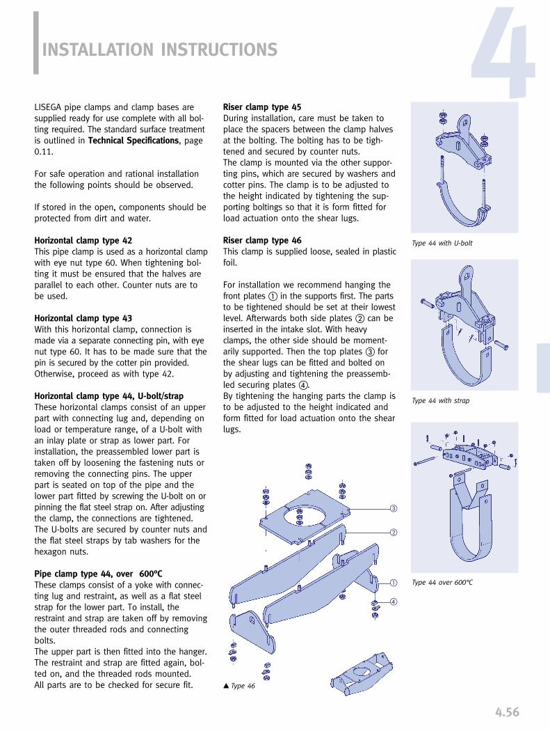
INSTALLATION INSTRUCTIONS
LISEGA pipe clamps and clamp bases aresupplied ready for use complete with all bol-ting required. The standard surface treatmentis outlined in Technical Specifications, page0.11.
For safe operation and rational installationthe following points should be observed.
If stored in the open, components should beprotected from dirt and water.
Horizontal clamp type 42This pipe clamp is used as a horizontal clampwith eye nut type 60. When tightening bol-ting it must be ensured that the halves areparallel to each other. Counter nuts are tobe used.
Horizontal clamp type 43With this horizontal clamp, connection ismade via a separate connecting pin, with eyenut type 60. It has to be made sure that thepin is secured by the cotter pin provided.Otherwise, proceed as with type 42.
Horizontal clamp type 44, U-bolt/strapThese horizontal clamps consist of an upperpart with connecting lug and, depending onload or temperature range, of a U-bolt withan inlay plate or strap as lower part. Forinstallation, the preassembled lower part istaken off by loosening the fastening nuts orremoving the connecting pins. The upperpart is seated on top of the pipe and thelower part fitted by screwing the U-bolt on orpinning the flat steel strap on. After adjustingthe clamp, the connections are tightened.The U-bolts are secured by counter nuts andthe flat steel straps by tab washers for thehexagon nuts.
Pipe clamp type 44, over 600°CThese clamps consist of a yoke with connec-ting lug and restraint, as well as a flat steelstrap for the lower part. To install, therestraint and strap are taken off by removingthe outer threaded rods and connectingbolts. The upper part is then fitted into the hanger.The restraint and strap are fitted again, bol-ted on, and the threaded rods mounted. All parts are to be checked for secure fit.
Type 44 with U-bolt
Type 44 with strap
Type 44 over 600°C
� Type 46
Riser clamp type 45During installation, care must be taken toplace the spacers between the clamp halvesat the bolting. The bolting has to be tigh-tened and secured by counter nuts.The clamp is mounted via the other suppor-ting pins, which are secured by washers andcotter pins. The clamp is to be adjusted tothe height indicated by tightening the sup-porting boltings so that it is form fitted forload actuation onto the shear lugs.
Riser clamp type 46This clamp is supplied loose, sealed in plasticfoil.
For installation we recommend hanging thefront plates � in the supports first. The partsto be tightened should be set at their lowestlevel. Afterwards both side plates � can beinserted in the intake slot. With heavyclamps, the other side should be moment-arily supported. Then the top plates � forthe shear lugs can be fitted and bolted onby adjusting and tightening the preassemb-led securing plates �. By tightening the hanging parts the clamp isto be adjusted to the height indicated andform fitted for load actuation onto the shearlugs.
�
�
�
�
4.56
4

� Type 48
Type 49 .. .3, 4, 5
Type 49 .. .3, 4
Type 49 .. .1 and 49 .. .2
Riser clamp type 48This clamp is supplied loose, sealed in plasticfoil.
First, one of the side plates � should beprepared using threaded rods �. For instal-lation, both side plates are to be seated onthe trunnions and connected by the rods,and the nuts only lightly tightened.
�
�
�
�
For heavy clamps, support with woodenblocks or ropes is required.
The front plates � are now fitted into theintake slots and connected to the hangingparts. Secure connection of the front andside plates is made by adjusting and tigh-tening the preassembled securing plates �.By tightening the supports the clamp is tobe adjusted to the height indicated andform fitted for load actuation to the trun-nions.
Clamp bases type 49LISEGA clamp bases are sliding supports,connected to the pipe by clamping tension.During installation it is essential that thebase plate lies flush and can glide unob-structed over the given stretches.
If required, the base plate may be weldedto the supporting surface.
According to the particular field of applica-tion, different designs are used with regardto support height, pipe diameter, support loadand operating temperature. The followingpoints are hereby to be observed:
Type 49 .. .1 and 49 .. .2This clamp base consists of two halves to befitted to each side of the pipes. The cornered
ends form the base plate. In the lowerpart, both halves are firmly connected to
each other by bolting. Through clampingtension, the upper bolting secures theclamp base against slipping.
Type 49 .. .3 and 49 .. .5The foot of this clamp base forms a solidsupport into which the pipe can be fitted.The upper part, providing clamping tension,consists of half a clamp and is to be securelybolted.
4.57

PIPE BEARING AND SADDLE COMPONENTS
PRODUCT GROUP
5


Roller bearings, type 51 to 53______________________________________ 5.1
Cylinder roller bearings, type 51 .. 19 ______________________________ 5.3
Double taper roller bearings, single, type 52 .. 19 ____________________ 5.3
Double taper roller bearings, movable, type 52 .. 29 __________________ 5.3
Double cylinder roller bearings, type 53 .. 19 ________________________ 5.4
Double cylinder roller bearings, type 53 .. 29 ________________________ 5.4
Pipe saddle for welding on, type 54 .. 19____________________________ 5.5
Pipe saddle with pipe clamp, type 54 .. 29 __________________________ 5.5
Support tray with pipe clamp, type 54 .. 39__________________________ 5.6
Lift-off restraint, type 55 .. 19 ______________________________________ 5.6
Insulated pipe supports, type 56 __________________________________ 5.7
Cold block pipe supports, type 56 ________________________________ 5.10
Weld-on pipe shoes, type 57 .. 11 and 57 .. 12 ____________________ 5.11
Stanchions for horizontal pipes, type 58 ..1. and 58 .. 2.______________ 5.12
Stanchions for short radius elbows
(R� OD), type 58 .. 1. and 58 .. 2. ________________________________ 5.13
Stanchions for long radius elbows
(R� 1.5OD), type 58 .. 1. and 58 .. 2. ______________________________ 5.14
Stanchions, type 58 ____________________________________________ 5.15
Elbow pads, type 58 .. 3. ________________________________________ 5.15
0
1
2
3
4
6
7
8
9
PRODUCTGROUP
5.0
PIPE BEARINGS AND SADDLE COMPONENTS
CONTENTS PAGE
5
5
0
1
2
3
4
6
7
8
9

5.1
ROLLER BEARINGSTYPE 51 TO 53
LISEGA – Standard Roller Bearings & Pipe SaddlesThese items are standardized in LISEGAProduct Group 5 for a wide range of applic-ations.
For applications outside the standard range,special designs can be offered.
Specification and design of roller bearingsIn the design of standard components, prac-tical requirements find special consideration.
The standard roller bearing is hot-dip galvan-ized and provides optimum corrosion protec-tion. Except for the movable double cylinderroller bearing Type 53 .. 29, weldings havebeen dispensed with.
The bearing axles are made from austeniticmaterial and have a polished surface. The slide bearings incorporate bushings madefrom a Teflon bronze sintered compound mat-erial fitted into the roller. The bearings aremaintenance free and guarantee dry runningqualities. The formed shoulder of each bushingminimizes the stick-slip drag effect on lateralloading. The bearing axles are permanentlyfixed in the middle section of the base. Spec-ial locking on the side bracket is not required.
The rollers are made from high tensile carbonsteel. Their outer surfaces are machined.
To compensate for misaligned anchor bolts,on site, the base holes are slotted for addi-tional adjustment.
The height dimensions (E) within a load grouprange are identical for all roller bearings, inc-luding the lateral movement type.
Information regarding material codes, stan-dards, calculations and weldings are givenin the Technical Specification on page 0.9and 0.10
Manufacture and StoringFor frequently used items, efficient serial prod-uction and stocking can be achieved throughstandardization.
Modern order logistics is possible through asingle fabrication process or in small lots,thus ensuring short fabrication and deliverytimes.
Technical Data for Roller Bearings
➜ rolling resistance of the rollers max 4%
➜ rolling resistance on lateral movement max 4%
➜ temperature range at nominal load -30°C to 80°C
➜ permissible lateral loading 35% of nominal load
➜ permissible lift-off load 10% of nominal load
Piping systems arrangedhorizontally over longstretches are placed onsupports. To allow normalthermal movement, thesupport points are designedas either sliding or rollertypes.
For larger diameter pipingand especially when fluidsand insulation produce highloads, roller bearings prov-ide the optimum solution.

5
5.2
INSTALLATION INSTRUCTIONS
Roller BearingsThe roller bearings can be fixed by simplebolt connections or welded to the contactsurface of the pipe support. In each case thecomplete width of the base plate must besupported and secured.
Due to the slotted holes, roller bearings caneasily be adjusted even with slightly misal-igned anchor bolts.
Pipe SaddlesWelded pipe saddles are supplied coated witha weldable primer (30µm) (see TechnicalSpecification page 0.10).
Care must be taken that the specified min-imum weld size is applied.
Pipe saddles with clamps are supplied readyto install.
Care must be taken to ensure the correct pos-itioning and adequate presetting of the bolts.
Lift-off restraintsWhen installing the lift-off restraint plate, caremust be taken to ensure that the gap bet-ween plate and roller is sufficient for normalmovement along the whole travel range.
The special design and quality of man-ufacture provide the following applicationbenefits:
➜ maintenance of minimum roll resistance (max 4%)
➜ takeover of realistic lateral loading for double taper and double cylinder roller bearings (35% of the support load)
➜ whole support load can be carried by just one roller of the double cylinder type
➜ absorption of lateral displacements bysideways sliding designs
➜ simple and safe design of lift-off restraints
➜ use of pipe saddles enables favorable load transfer into the pipe wall
➜ design of pipe saddles minimizes heat transfer
➜ hot dip galvanized corrosion protection for all roller bearings
➜ maintenance free operation
➜ stainless steel roller axle
➜ Teflon bronze compound bushes
➜ large range of sizes OD 60mm – OD 1350mm)
➜ large load range (max support load 120kN)
➜ short support height (see selection chart for E dimension)

5.3
Single cylinder roller bearingtype 51 08 19 to 51 35 19
Order details:Type 51 .. 19
Double taper roller bearing(single)type 52 04 19 to 52 35 19
� E = 1.064 · R +x
Order details:Type 52 .. 19
��
Double taper roller bearing (sideways movable)type 52 04 29 to 52 35 29
� E = 1.064 · R +x
Order details:Type 52 .. 29
travel 50mm
Type
51 08 1951 16 1951 35 19
A1 A2 B E F G a b sWeight
(kg)Load FN
(kN)
AR B C F G a b s xWeight
(kg)E�
min. max.
Load FN
(kN)Type
52 04 1952 08 1952 16 1952 35 19
AR B C F G a b s xWeight
(kg)E�
min. max.
Load FN
(kN)Type
52 04 2952 08 2952 16 2952 35 29
81635
90120145
70100120
80100130
506085
355560
607595
202426
101214
56
10
1.22.45.5
48
1635
105135165230
90100120160
7085
100135
557590
130
707590
120
20202426
10101214
468
12
546474
102
1.83.35.4
14.0
83 160153 202191 250247 347
27 - 10084 - 130
110 - 165136 - 230
48
1635
155185215280
90100120160
7085
100135
105120140180
707590
120
20202426
10101214
468
12
546474
102
2.03.66.0
15.5
83 160153 202191 250247 347
27 - 10084 - 130
110 - 165136 - 230
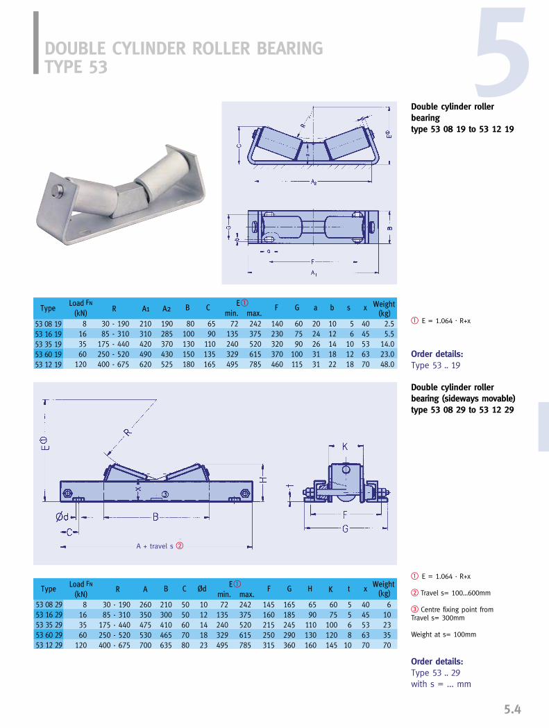
5
5.4
Order details:Type 53 .. 29with s = ... mm
Double cylinder roller bearingtype 53 08 19 to 53 12 19
� E = 1.064 · R+x
Order details:Type 53 .. 19
DOUBLE CYLINDER ROLLER BEARINGTYPE 53
A + travel s �
Double cylinder roller bearing (sideways movable)type 53 08 29 to 53 12 29
� E = 1.064 · R+x
� Travel s= 100…600mm
� Centre fixing point from Travel s= 300mm
Weight at s= 100mm
A1R A2 B C F G a b s x Weight(kg)
E�
min. max.
Load FN
(kN)Type
53 08 1953 16 1953 35 1953 60 1953 12 19
AR B C Ød F G H tK xWeight
(kg)E�
min. max.
Load FN
(kN)Type
53 08 2953 16 2953 35 2953 60 2953 12 29
8163560
120
210310420490620
190285370430525
80100130150180
6590
110135165
140230320370460
607590
100115
2024263131
1012141822
56
101218
4045536370
2.55.5
14.023.048.0
72 242135 375240 520329 615495 785
30 - 19085 - 310
175 - 440250 - 520400 - 675
8163560
120
260350475530700
210300410465635
5050607080
1012141823
145160215250315
165185245290360
6590
110130160
6075
100120145
5568
10
4045536370
610233570
30 - 19085 - 310
175 - 440250 - 520400 - 675
72 242135 375240 520329 615495 785
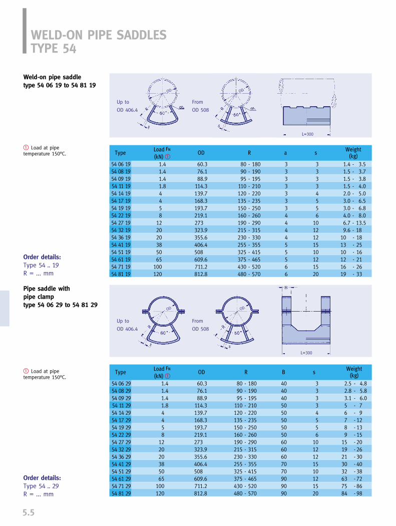
5.5
WELD-ON PIPE SADDLESTYPE 54
Pipe saddle with pipe clamptype 54 06 29 to 54 81 29
� Load at pipe temperature 150°C.
Order details:Type 54 .. 29R = ... mm
Weld-on pipe saddletype 54 06 19 to 54 81 19
� Load at pipe temperature 150°C.
Order details:Type 54 .. 19R = ... mm
Up to
OD 406.4
From
OD 508
From
OD 508
Up to
OD 406.4
ODOD
OD OD
L=300
L=300
Type
54 06 1954 08 1954 09 1954 11 1954 14 1954 17 1954 19 1954 22 1954 27 1954 32 1954 36 1954 41 1954 51 1954 61 1954 71 1954 81 19
ODWeight
(kg)a s
Load FN
(kN) �R
Type
54 06 2954 08 2954 09 2954 11 2954 14 2954 17 2954 19 2954 22 2954 27 2954 32 2954 36 2954 41 2954 51 2954 61 2954 71 2954 81 29
ODWeight
(kg)BR
Load FN
(kN) �s
1.41.41.41.84458
122020385065
100120
60.376.188.9
114.3139.7168.3193.7219.1273323.9355.6406.4508609.6711.2812.8
80 - 18090 - 19095 - 195
110 - 210120 - 220135 - 235150 - 250160 - 260190 - 290215 - 315230 - 330255 - 355325 - 415375 - 465 430 - 520480 - 570
1.4 - 3.51.5 - 3.71.5 - 3.81.5 - 4.02.0 - 5.03.0 - 6.53.0 - 6.84.0 - 8.06.7 - 13.59.6 - 18
10 - 1813 - 2510 - 1612 - 2116 - 2619 - 33
3333333444455566
33334556
1012121510121520
1.41.41.41.84458
122020385065
100120
60.376.188.9
114.3139.7168.3193.7219.1273323.9355.6406.4508609.6711.2812.8
40404050505050506060607070909090
33334556
1012121510121520
80 - 18090 - 19095 - 195
110 - 210120 - 220135 - 235150 - 250160 - 260190 - 290215 - 315230 - 330255 - 355325 - 415375 - 465 430 - 520480 - 570
2.5 - 4.82.8 - 5.83.1 - 6.05 - 76 - 97 - 128 - 139 - 15
15 - 2019 - 2621 - 3030 - 4032 - 3863 - 7275 - 8684 - 98
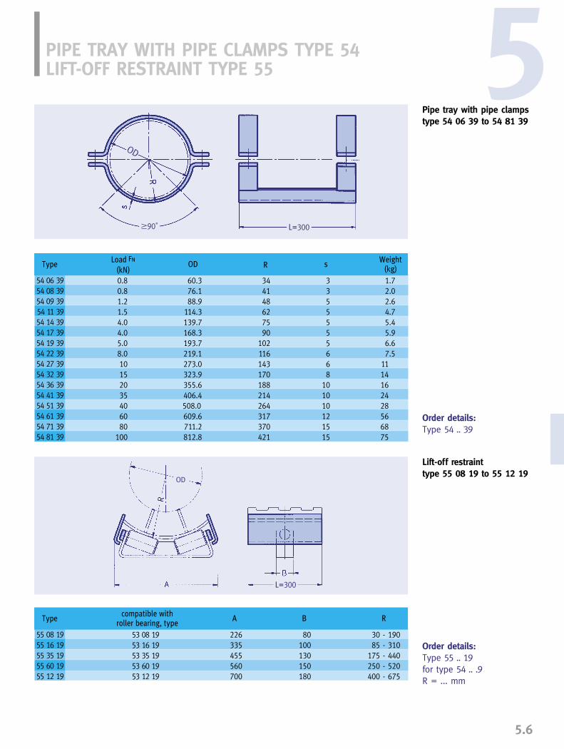
5
5.6
Pipe tray with pipe clampstype 54 06 39 to 54 81 39
Order details:Type 54 .. 39
Lift-off restrainttype 55 08 19 to 55 12 19
Order details:Type 55 .. 19for type 54 .. .9R = ... mm
PIPE TRAY WITH PIPE CLAMPS TYPE 54 LIFT-OFF RESTRAINT TYPE 55
OD
OD
L=300�90˚
L=300
Type
54 06 3954 08 3954 09 3954 11 3954 14 3954 17 3954 19 3954 22 3954 27 3954 32 3954 36 3954 41 3954 51 3954 61 3954 71 3954 81 39
ODWeight
(kg)Load FN
(kN)sR
A B Rcompatible with
roller bearing, typeType
55 08 1955 16 1955 35 1955 60 1955 12 19
0.80.81.21.54.04.05.08.010152035406080
100
60.376.188.9
114.3139.7168.3193.7219.1273.0323.9355.6406.4508.0609.6711.2812.8
344148627590
102116143170188214264317370421
3355555668
101010121515
1.72.02.64.75.45.96.67.5
1114162428566875
53 08 1953 16 1953 35 1953 60 1953 12 19
226335455560700
80100130150180
30 - 19085 - 310
175 - 440250 - 520400 - 675

INSULATED PIPE SUPPORTSTYPE 56
5.7
Pipe Supports for Cryogenic ApplicationsLISEGA offer a complete range of insulatedpipe supports for all types of cryogenic pipingapplications. Typically, these include industrialprocesses involving the production, transpor-tation and distribution of liquefied gasesincluding methane, propane, butane (LNG),ethylene, oxygen, nitrogen and ammonia (LPG).
LISEGA standard insulated pipe supports aredesigned in accordance with recognized engin-eering specifications and international stan-dards for pipes ranging in size from OD21.3mm to OD 914mm with insulation thick-nesses from 25mm up to 250mm. The sup-ports are manufactured using materials suit-able for the loads specified and for tempera-tures ranging from ambient to –196°C.
Insulation Material
The insulation material thatforms an integral part of the insul-
ated pipe support assembly is manufacturedusing fire-retarding high-density polyurethane(PUF) foam. For the supply of the PUF com-ponents and consumables, LISEGA have formed an alliance with Bains HardingIndustries Pty. Ltd., Australia. With more thantwenty five years experience in industrialinsulation, the company has extensive experience in the manufacture of rigid polyurethane insulation materials includinghighdensity moulded products and provideconstruction and maintenance services tothe liquefied natural gas industry (LNG) inAustralia and South East Asia.
PUF ManufactureThe PUF is monolithically molded in heavyduty steel molds under carefully controlledtemperature and humidity conditions. Thisensures compliance with dimensional spec-ifications and provides clean, sharp edgesthat fit neatly with the adjacent line insul-ation material on site. Careful attention isgiven to the curing of the PUF after moldingto ensure dimensional stability.
Both single and multilayer PUF cradlesystems are manufactured in accordance
with ASTM C-585 and incorporate steppedradial and offset longitudinal joints. This pro-vides a reliable interlocking interface witheach layer of the adjacent line insulation onsite and prevents a direct vapor path to theinsulation surface.
All exposed PUF cradle surfaces are sealedwith cryogenic fire-retarding elastomeric vaporbarrier mastic to prevent moisture ingress.A laminated aluminum/polyester foil is bon-ded to the outermost surface of the PUFcradle assembly. This has an overlap allo-wance designed to cover the adjacent lineinsulation material on site. Finally, a sheetmetal jacket forms part of the PUF cradleassembly and fits over the aluminum/poly-ester foil to provide additional support andinsulation protection.
The PUF cradles are available in three stan-dard densities to provide for varying loadrequirements –
160 kg/m3, 224 kg/m3, 320 kg/m3.

5.8
5Steel Clamp BaseLISEGA standard insulated pipe supports aredesigned to clamp onto the pipe mechan-ically. The steel clamp base support that the PUFcradle assembly fits into is manufacturedfrom carbon steel and supplied with a hotdip galvanized finish as standard. Material grades, welding and surface treatmentare in accordance with the LISEGA standardspecifications shown on pages 0.9 and 0.10of the catalog.
The quality control system employed by LISEGAin the manufacture and assembly of pipesupports is described on page 0.15. The in-spection and test procedure includes a trialfitting of each pipe support to a suitablesection of pipe to ensure compliance withthe specification.
Nominal thickness of insulation
80100130150180200250
Thickness of the layering
40 / 4050 / 50
30 / 50 / 5050 / 50 / 5050 / 80 / 50
50 / 100 / 5050 / 50 / 100 / 50
Density
Compressive strength
Linear coefficient of
expansion
Closed cell content
Thermal conductivity
Unit
kg/m3
MPaMPa1/K
%
W/mKW/mK
20°C-165°C
20°C-165°C
ASTM D1622ASTM D1621
BS 4370
ASTM D2856ASTM C177
160
� 2.0� 3.675
� 70x10-6
� 90
� 0.032� 0.021
224
� 4.0� 5.75
� 70x10-6
� 90
� 0.035� 0.027
320
� 7.0� 12.25
� 70x10-6
� 90
� 0.041� 0.034
Test standard
Material properties of the insulation

DWidth of theclamp base B
75�230�300�450�600�800
… 230… 300… 450… 600… 800
100150200300400500
CRYOGENIC CLAMP BASES TYPE 56 .. 10 TO 56 .. 69
5.9
Cryogenic clamp basesType 56 01 10 to 56 91 69
.. .. 1. Length C: 300; density of insulation 160kg/m3
.. .. 2. Length C: 500; density of insulation 160kg/m3
.. .. 4. Length C: 500; density of insulation 224kg/m3
.. .. 6. Length C: 500; density of insulation 320kg/m3
C minus 20
sheet metal jacket
OD
150
100
50
� Maximum lateral loading 30% of vertical load
265290320345370400425480
56 .. 6.
Table of outer diameter D of the insulation (excluding sheet metal jacket)
Nominal insulation thicknessType
56 01 ..56 02 ..56 03 ..56 06 ..56 09 ..56 11 ..56 17 ..56 22 ..56 27 ..56 32 ..56 36 ..56 41 ..56 46 ..56 51 ..56 56 ..56 61 ..56 66 ..56 71 ..56 76 ..56 81 ..56 91 ..
OD
21.326.933.760.388.9
114.3168.3219.1273.0323.9355.6406.4457.2508.0558.8609.6660.4711.2762.0812.8914.4
Permissible load (kN) at –170°C �
2.32.93.76.79.8213140506065758494
100110120130140150165
56 .. 2.
25 40 50 80 100 130 150 180 200
6th digit of type designation
717784
110139164218269323
56 .. .0
101107114140169194248199353404
56 .. .1
121127134160189214268319373424456
56 .. .2
181187194220249274328379433484516566
56 .. .3
221227234260289314368419473524556606657708759810860911962
10131114
56 .. .4
287294320349374428479533584616666717768918870920971
102210731174
56 .. .5
360689414468519573624659706757808859910960
1011106211131214
56 .. .6
449474528579633684716766817868919970
10201071112211731274
56 .. .7
514568619673724756806857908959
101010601111116212131314
56 .. .8
250
614668719773824856906957
10081059111011601211126213131414
56 .. .9
2.32.93.76.79.8121824303639455056626773798490
100
56 .. 1.
105120135150165180195210225240275
56 .. 4.5th digit of type designation
�160

Steel Clamp BasesLISEGA standard cold block pipe supports aredesigned to mechanically clamp onto the pipe.The steel clamp base support is manufacturedfrom stainless steel and is supplied self-coloras standard. The cold block is bolted betweenthe underside of the clamp base and a carbonsteel base plate. Material grades, welding andsurface treatment are in accordance with theLISEGA standard specifications.
Other pipe support configurations can be sup-plied (pipe support stanchions, cradles, anchors)on request.
LISEGA cold block pipe supports are suppliedwith detailed installation instructions. Each pipesupport is clearly marked in accordance withthe LISEGA Type Designation System.
LISEGA cold block pipe supports are suppliedfully assembled and packed to protect the fin-ished product from superficial damage and mois-ture ingress during storage and transportation.
+20
0.309
Temperature °C
Thermal
conductivity W / (Km)
-100
0.243
-180
0.205
-196
0.199
Pipe Supports for Cryogenic ApplicationsLISEGA standard cold block supports are de-signed in accordance with recognized engin-eering specifications and international stand-ards for pipes ranging in size from OD 21.3mmto OD 914mm. The supports are manufacturedusing materials that are suitable for the loadsspecified and temperatures ranging fromambient to –196°C.
Cold Block MaterialThe cold block insulation material formingan integral part of the cold block pipe supportassembly is designed to provide a sufficientthermal insulation barrier between the pipeoperating at subzero temperatures and thesupporting structure that is at ambient tem-perature.
LISEGA standard cold block supports incor-porate Lignostone® densified wood blocksthat are manufactured from selected beechveneers, impregnated under vacuum withthermosetting synthetic resin and densifiedunder heat and pressure. The Lignostone®
blocks combine high strength with low ther-mal conductivity, have proven cryogeniccapability and are used exclusively for coldpipe applications throughout the world.
Alternative cold block insulation materialssuitable for cryogenic applications are avail-able on request.
COLD BLOCK PIPE SUPPORTSTYPE 56 .. 91
5.10
5
� permissible loads at cryogenic temperature
OD
J
A
Length=B
ODpermissible
load in kN �A B H E G
21.326.933.760.388.9
114.3168.3219.1273.0323.9355.6406.4457.2508.0558.8609.6660.4711.2762.0812.8914.4
1.31.62.13.75.57.1
101317202225283134384144475057
175175175175175175175240240360360360410440490490590590590590690
200200200200200200200200200400400400400400400400400400400400400
100100100100100150150150150150150150150150150150150150150150150
111113117130144207234260287312328353379404429455480506531556607
738084
117139183223258315354375438477528598640690741792843944
C
364042587092
111129158177187219239264299320345371396421472
t
101010101010101015151515152020202020202025
Type
56 01 9156 02 9156 03 9156 06 9156 09 9156 11 9156 17 9156 22 9156 27 9156 32 9156 36 9156 41 9156 46 9156 51 9156 56 9156 61 9156 66 9156 71 9156 76 9156 81 9156 91 91
J
135135135135135135135200200320320320370400450450550550550550650

5.11
WELD-ON PIPE SHOESTYPE 57 .. 11 AND 57 .. 12
Weld-on pipe shoes madefrom T/C sectionFor use with small pipeloads and temperature � 80°C
type 57 .. 11 to 57 .. 12
Material: S235JRG2
Surface: primer
Type designation:57 .. 11 (T Shoe)57 .. 12 (C Shoe)
� Field weld – For the weldsize and permissible loadsspecified, the stress in theweld is less than 50 N/mm2.
Order details:Weld-on pipe shoetype 57 .. 1.
�
�
Type
57 03 1157 03 1157 03 1157 03 1157 03 1157 07 1157 07 1157 07 1157 07 1157 13 1157 13 1157 13 1157 13 1157 13 1157 13 1157 24 1257 24 1257 24 1257 24 1257 24 1257 36 1257 36 1257 36 1257 42 1257 42 1257 42 1257 51 1257 51 1257 61 1257 61 12
Load F [kN]at 80°C
OD A B Ea � Weight
(kg)
21.326.933.742.448.360.373.076.188.9
108.0114.3133.0139.7159.0168.3193.7219.1244.5267.0273.0323.9355.6368.0406.4419.0457.2508.0558.8609.6660.4
1.01.01.01.01.01.51.51.51.52.02.02.02.02.02.06.06.06.06.06.08.0
101010101215152020
100100100100100150150150150150150150150150150250250250250250250250250250250250250250250250
707070707070707070
100100100100100100100100100100100160160160200200200240240300300
333333333333333555555555555555
0.80.80.80.80.81.21.21.21.22.52.52.52.52.52.52.72.72.72.72.74.74.74.76.36.36.38.38.3
11.611.6
8183879194
100107108115154157167170180184135150163175178210226233255262283312340370400

5
5.12
Order details:Type 58 24 21, E= 800mm
STANCHIONS FOR HORIZONTAL PIPESTYPE 58 .. 1. AND 58 .. 2.
� ... � see page 5.15
Example: Telescopic stanchion for pipe OD= 244.5mm,E= 800 (sliding)
The length of the stanchion is: L= E-N see data fromthe selection table L=800-122= 678mm.
For stanchion D= 88.9mm (designation “d”)
Permissible load = 0.36 x 11kN (see tables on page 5.15) = 3.96kN
Type 58 .. 112
Type 58 .. 212
OD
OD
E maxOD NStanchion
typeE minD x s aType
58 05 .158 06 .158 06 .258 07 .158 07 .258 08 .158 08 .258 09 .158 09 .258 10 .158 10 .258 11 .158 11 .258 13 .158 13 .258 14 .158 14 .258 16 .158 16 .258 17 .158 17 .258 19 .158 19 .258 22 .158 22 .258 24 .158 24 .258 26 .158 26 .258 27 .158 27 .258 32 .158 32 .258 36 .158 36 .258 37 .158 37 .258 41 .158 41 .258 42 .158 42 .258 46 .158 46 .258 51 .158 51 .258 56 .158 56 .258 61 .158 66 .158 71 .158 76 .158 81 .158 91 .1
48.360.360.373.073.076.176.188.988.9
108.0108.0114.3114.3133.0133.0139.7139.7159.0159.0168.3168.3193.7193.7219.1219.1244.5244.5267.0267.0273.0273.0323.9323.9355.6355.6368.0368.0406.4406.4419.0419.0457.2457.2508.0508.0558.8558.8609.6660.4711.2762.0812.8914.4
33.7 x 4.533.7 x 4.548.3 x 533.7 x 4.548.3 x 5 33.7 x 4.548.3 x 533.7 x 4.548.3 x 548.3 x 573.0 x 5.648.3 x 573.0 x 5.648.3 x 573.0 x 5.673.0 x 5.688.9 x 5.673.0 x 5.688.9 x 5.673.0 x 5.688.9 x 5.688.9 x 5.6
114.3 x 8.888.9 x 5.6
114.3 x 8.888.9 x 5.6
114.3 x 8.8114.3 x 8.8139.7 x 10114.3 x 8.8139.7 x 10139.7 x 10219.1 x 8139.7 x 10219.1 x 8139.7 x 10219.1 x 8139.7 x 10219.1 x 8139.7 x 10219.1 x 8219.1 x 8323.9 x 10219.1 x 8323.9 x 10219.1 x 8323.9 x 10323.9 x 10323.9 x 10323.9 x 10323.9 x 10323.9 x 10323.9 x 10
aababababbcbcbccdcdcddededeefeffgfgfgfgfgghghghhhhhhh
33333333333333333333335353557577575757575575757777777
2430303737383844445454575767677070808084849797
110110122122134134137137162162178178184184203203210210229229254254279279305330356381406457
250250250250250250250250250300300300300300300300300300300300300350350350350350350350350350350400400400400400400450450450450500500500500550550550600600650650700
11001100110011001100110011001100110011501150115011501150115011501150115011501150115011501150120012001200120012001200120012001250125012501250125012501300130013001300130013001350135013501350140014001450145015001550
��
15075

5.13
STANCHIONS FOR SHORT RADIUS ELBOWS(R� OD) TYPE 58 .. 1. AND 58 .. 2.
Order details:Stanchions for short radius elbows R � OD type 58 42 23, E = 750mm
� ... � see page 5.15
Example: Stanchion for short radius elbow R� OD, OD= 419mm, E= 750 (anchor)
Length of stanchion: L= E-N (see data from the selection table), L=750-50= 700mm.
For stanchion D= 139.7mm (designation “f”)
Permissible load = 0.41 x 22.5kN (see tables on page 5.15) = 9.2kN
Type 58 .. 134
Type 58 .. 234
OD
OD
E maxOD NStanchion
typeE minD x s aType
58 05 .358 06 .358 06 .458 07 .358 07 .458 08 .358 08 .458 09 .358 09 .458 10 .358 10 .458 11 .358 11 .458 13 .358 13 .458 14 .358 14 .458 16 .358 16 .458 17 .358 17 .458 19 .358 19 .458 22 .358 22 .458 24 .358 24 .458 26 .358 26 .458 27 .358 27 .458 32 .358 32 .458 36 .358 36 .458 37 .358 37 .458 41 .358 41 .458 42 .358 42 .458 46 .358 46 .458 51 .358 51 .458 56 .358 56 .458 61 .358 66 .358 71 .358 76 .358 81 .358 91 .3
��
48.360.360.373.073.076.176.188.988.9
108.0108.0114.3114.3133.0133.0139.7139.7159.0159.0168.3168.3193.7193.7219.1219.1244.5244.5267.0267.0273.0273.0323.9323.9355.6355.6368.0368.0406.4406.4419.0419.0457.2457.2508.0508.0558.8558.8609.6660.4711.2762.0812.8914.4
33.7 x 4.533.7 x 4.548.3 x 533.7 x 4.548.3 x 5 33.7 x 4.548.3 x 533.7 x 4.548.3 x 548.3 x 573.0 x 5.648.3 x 573.0 x 5.648.3 x 573.0 x 5.673.0 x 5.688.9 x 5.673.0 x 5.688.9 x 5.673.0 x 5.688.9 x 5.688.9 x 5.6
114.3 x 8.888.9 x 5.6
114.3 x 8.888.9 x 5.6
114.3 x 8.8114.3 x 8.8139.7 x 10114.3 x 8.8139.7 x 10139.7 x 10219.1 x 8139.7 x 10219.1 x 8139.7 x 10219.1 x 8139.7 x 10219.1 x 8139.7 x 10219.1 x 8219.1 x 8323.9 x 10219.1 x 8323.9 x 10219.1 x 8323.9 x 10323.9 x 10323.9 x 10323.9 x 10323.9 x 10323.9 x 10323.9 x 10
aababababbcbcbccdcdcddededeefeffgfgfgfgfgghghghhhhhhh
33333333333333333333335353557577575757575575757777777
10101015151515151515152020202025252525303030303535353540404545505040404545505050505555606065657080859095
110
250250250250250250250250250250250250250250250300300300300300300300300300300300300300300350350350350350350350350350350350350400400400400450450450450450450500550
11001100110011001100110011001100110011001100110011001100110011001100110011001100110011001100110011001100110011001100110011001100110011001100110011001100110011001100115011501150115011501150115011501150115011501200
15075

5.14
5
� ... � see page 5.15
Example: Stanchion for long radius elbow R� 1.5 OD,OD= 419mm, E= 750 (anchor)
Length of stanchion: L= E+N (see data from the selec-tion table), L=750+75= 825mm.
For stanchion D= 139.7mm (designation “f”)
Permissible load = 0.37 x 22.5kN (see tables on page 5.15) = 8.3kN
STANCHIONS FOR LONG RADIUS ELBOWS R� 1.5 OD, TYPE 58 .. 1. AND 58 .. 2.
Order details:Stanchions for long radius elbows R � 1.5 ODtype 58 42 25, E = 750mm
Type 58 .. 156
Type 58 .. 256
OD
E maxOD NStanchion
typeE minD x s aType
58 05 .558 06 .558 06 .658 07 .558 07 .658 08 .558 08 .658 09 .558 09 .658 10 .558 10 .658 11 .558 11 .658 13 .558 13 .658 14 .558 14 .658 16 .558 16 .658 17 .558 17 .658 19 .558 19 .658 22 .558 22 .658 24 .558 24 .658 26 .558 26 .658 27 .558 27 .658 32 .558 32 .658 36 .558 36 .658 37 .558 37 .658 41 .558 41 .658 42 .558 42 .658 46 .558 46 .658 51 .558 51 .658 56 .558 56 .658 61 .558 66 .558 71 .558 76 .558 81 .558 91 .5
48.360.360.373.073.076.176.188.988.9
108.0108.0114.3114.3133.0133.0139.7139.7159.0159.0168.3168.3193.7193.7219.1219.1244.5244.5267.0267.0273.0273.0323.9323.9355.6355.6368.0368.0406.4406.4419.0419.0457.2457.2508.0508.0558.8558.8609.6660.4711.2762.0812.8914.4
33.7 x 4.533.7 x 4.548.3 x 533.7 x 4.548.3 x 5 33.7 x 4.548.3 x 533.7 x 4.548.3 x 548.3 x 573.0 x 5.648.3 x 573.0 x 5.648.3 x 573.0 x 5.673.0 x 5.688.9 x 5.673.0 x 5.688.9 x 5.673.0 x 5.688.9 x 5.688.9 x 5.6
114.3 x 8.888.9 x 5.6
114.3 x 8.888.9 x 5.6
114.3 x 8.8114.3 x 8.8139.7 x 10114.3 x 8.8139.7 x 10139.7 x 10219.1 x 8139.7 x 10219.1 x 8139.7 x 10219.1 x 8139.7 x 10219.1 x 8139.7 x 10219.1 x 8219.1 x 8323.9 x 10219.1 x 8323.9 x 10219.1 x 8323.9 x 10323.9 x 10323.9 x 10323.9 x 10323.9 x 10323.9 x 10323.9 x 10
aababababbcbcbccdcdcddededeefeffgfgfgfgfgghghghhhhhhh
33333333333333333333335353557577575757575575757777777
00055005555
10101010151515151515202025252525303030304040656565657070757580809090
100100110115125135145160
200250250250250250250250250250250250250250250250250250250250250250250250250250250250250250250300300250250250250300300300300300300350350350350400400450450500550
11001050105010501050105010501050105010501050105010501050105010501050105010501050105010501050105010501050105010501050105010501050105010001000100010001000100010001000100010001000100010001000950950950950950900
�
�
15075
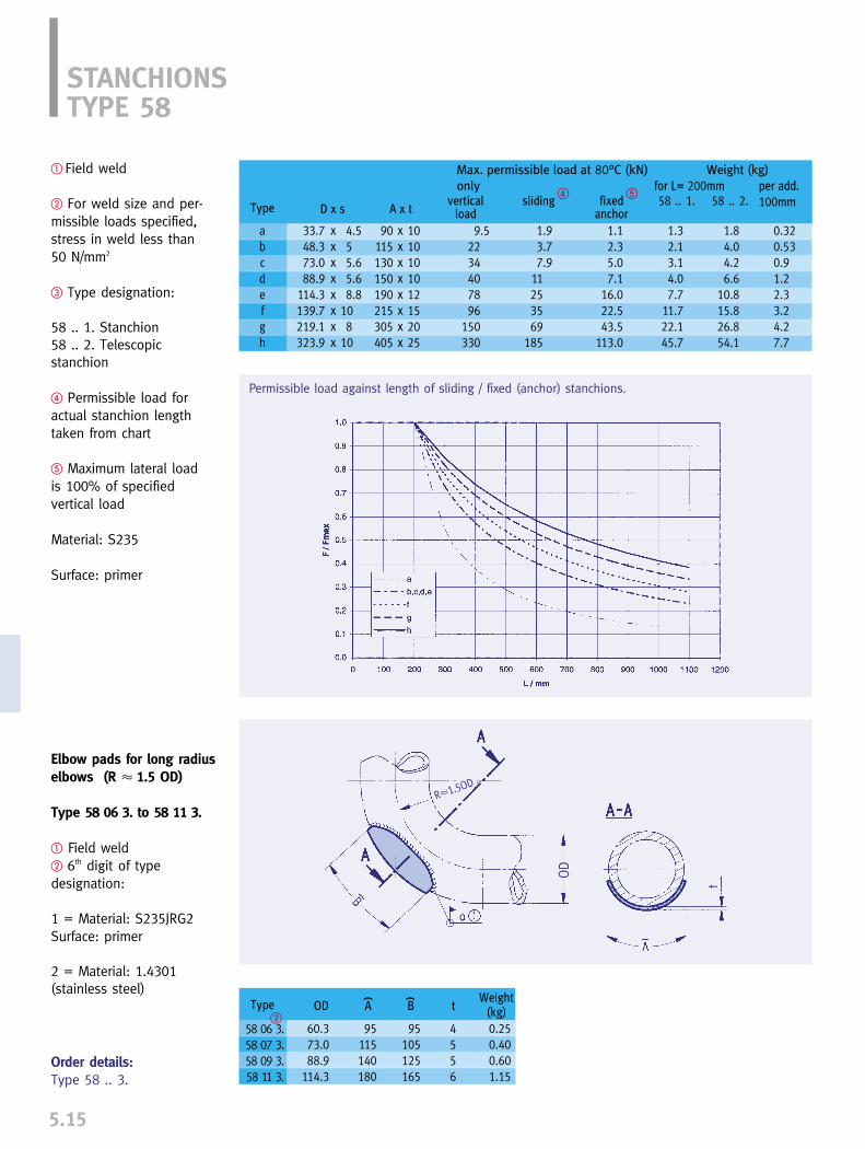
Weight (kg)
for L= 200mm per add.
100mm
Type
58 06 3.58 07 3.58 09 3.58 11 3.
OD A B tWeight
(kg)
60.373.088.9
114.3
95115140180
95105125165
4556
0.250.400.601.15
( (
�
5.15
Order details:Type 58 .. 3.
STANCHIONSTYPE 58
� Field weld
� For weld size and per-missible loads specified,stress in weld less than 50 N/mm2
� Type designation:
58 .. 1. Stanchion58 .. 2. Telescopic stanchion
� Permissible load foractual stanchion lengthtaken from chart
� Maximum lateral load is 100% of specified vertical load
Material: S235
Surface: primer
Elbow pads for long radiuselbows (R � 1.5 OD)
Type 58 06 3. to 58 11 3.
� Field weld� 6th digit of type designation:
1 = Material: S235JRG2Surface: primer
2 = Material: 1.4301 (stainless steel)
Permissible load against length of sliding / fixed (anchor) stanchions.
( (
R�1.5OD
OD
D x svertical
loadA x tsliding fixed
anchorType
abcdefgh
58 .. 1. 58 .. 2.
Max. permissible load at 80°C (kN)
only
33.7 x 4.548.3 x 573.0 x 5.688.9 x 5.6
114.3 x 8.8139.7 x 10219.1 x 8323.9 x 10
90 x 10115 x 10130 x 10150 x 10190 x 12215 x 15305 x 20405 x 25
9.52234407896
150330
1.93.77.9
11253569
185
1.12.35.07.1
16.022.543.5
113.0
1.32.13.14.07.7
11.722.145.7
1.84.04.26.6
10.815.826.854.1
0.320.530.91.22.33.24.27.7
� �

THREADED CONNECTING ELEMENTS
PRODUCT GROUP
6


PRODUCTGROUP 6
0
1
2
3
4
5
7
8
9
0
1
2
3
4
5
7
8
96.0
CONNECTING ELEMENTS
Connecting elements ______________________________________________6.1
Eye nut type 60 __________________________________________________6.2
Clevis with pin type 61 __________________________________________ 6.2
Turnbuckle type 62 ______________________________________________6.3
Rod coupling type 64 ____________________________________________ 6.3
Connecting rods__________________________________________________ 6.4
Hexagon nut type 63 ______________________________________________6.5
Tie rod LR type 65 ________________________________________________6.5
Stud bolt type 67 ________________________________________________ 6.5
Tie rod type 66 __________________________________________________6.6
Threaded rod type 67 ____________________________________________ 6.6
CONTENTS PAGE
6

LISEGA connecting components offer special advantages:
➜ universal application
➜ load and connection compatibility with the LISEGA modular system
➜ drop forged and heat treated
➜ standard electrogalvanized or if required, hot dip galvanized finish
➜ qualification by special type testing
CONNECTING ELEMENTSTYPE 60 TO 64
The components in Product Group 6 arespecially designed threaded elements forconnecting the attachment rods to othersupport components. In the load chains,they connect components that in part havedifferently designed connections such aslugs, clevises or eye nuts.
The connecting parts in Product Group 6form an independent group within themodular system and have been speciallydesigned for optimum suitability as pipesupport components.
The components are drop forged, and de-signed (apart from turnbuckles type 62) toallow slight length adjustments, despitetheir limited installation height.
The permissible loads correspond with theload table for statically determined pipesupports on page 0.5 of the Technical Specifications.
Eye nut Type 60 is used to join the rod to apin connection, the clevis Type 61 to join itto a lug connection.
Turnbuckle Type 62 is supplied with a right-hand thread at one end and a left-hand thread at the other. It is used togetherwith the tie rod Type 65 to provide lengthadjustment and presetting of the load chains.
Coupling Type 64 is used to produce rodlengths greater than 3m.
All threads (except in turnbuckles Type 62)are right-hand and available in metric or UNCstandard.
For corrosion protection, all components aresupplied complete with a standard electro-galvanized finish (zinc thickness approx. 15�m, yellow chromatized for metric andwhite for UNC threads). For use in particularlyaggressive environments, the componentscan be supplied with a hot dip galvanizedfinish.
Material certification can be supplied for allcomponents if required.
6.1
In the connection compo-nent field, precision fitthreads, reliable materialgrades and designs withsafe load reserves are theprerequisite for the depen-dability of the entire loadchain.
Eye nut, type 60
Rod coupling, type 64
Turnbuckle, type 62
Clevis with pin, type 61

Order details:Eye nut type 60 .. 1.
Eye nuttype 60 D9 19 to 60 50 12Material: P250GHdrop forged
from load group 40:Welded designMaterial: S355J2G3
EYE NUT TYPE 60CLEVIS WITH PIN TYPE 61
6.2
Clevis with pintype 61 D9 19 to 61 50 12Material: P250GHfrom load group 10:S355J2G3drop forged
from load group 40:flame cut designMaterial: S355J2G3
PinC35E + QT complete withcotter pin DIN EN ISO 1234and washer DIN 1441
Order details:Clevis type 61 .. 1.
Shape type 614012, 615012
Type
60 D9 1960 29 1260 39 1260 49 1260 59 1260 69 1260 79 1260 89 1260 99 1260 10 1260 20 1260 30 1260 40 1260 50 12
A
243344597288
100110120135150160220250
B
40607590
110127140157180200230230250280
C
111520253037455260657070
120140
D
17243035445060708095
105110125140
�d2
M10M12M16M20M24M30M36M42M48M56x4M64x4M68x4M72x4M80x4
d3
1317252935424752626272728292
E
254045556575758585
105130130100120
F
56
101015172025304040405060
G
15 1926354454627278808590
110125
x
15203035455265729595
100100150160
Weight(kg)
0.050.100.200.400.801.202.002.904.707.708.809.30
27.0045.00
Type
61 D9 1961 29 1261 39 1261 49 1261 59 1261 69 1261 79 1261 89 1261 99 1261 10 1261 20 1261 30 1261 40 1261 50 12
A
23334255657285
100120130155155150165
B
50708090
110130150170180215230230240260
C
1115202530354050606570708090
D
17253340465161728390
110110––
�d2
M10M12M16M20M24M30M36M42M48M56x4M64x4M68x4M72x4M80x4
�d1
1012162024334045506070708090
E
35505055658090
10095
120130125130140
F
1112172022273237425060605664
G
50607090
105125140165185210245245230240
H
25344457688093
110130150175175150165
K
2124324653648090
100120150150150180
L
5x98x12
11x1516x2119x2519x2922x3627x4033x4430x4535x5535x55
––
M
––––––––––––90
110
x
15203035455060708595
100105110120
Weight(kg)
0.10.20.41.01.62.74.47.2
10.414.824.424.442.060.0
6
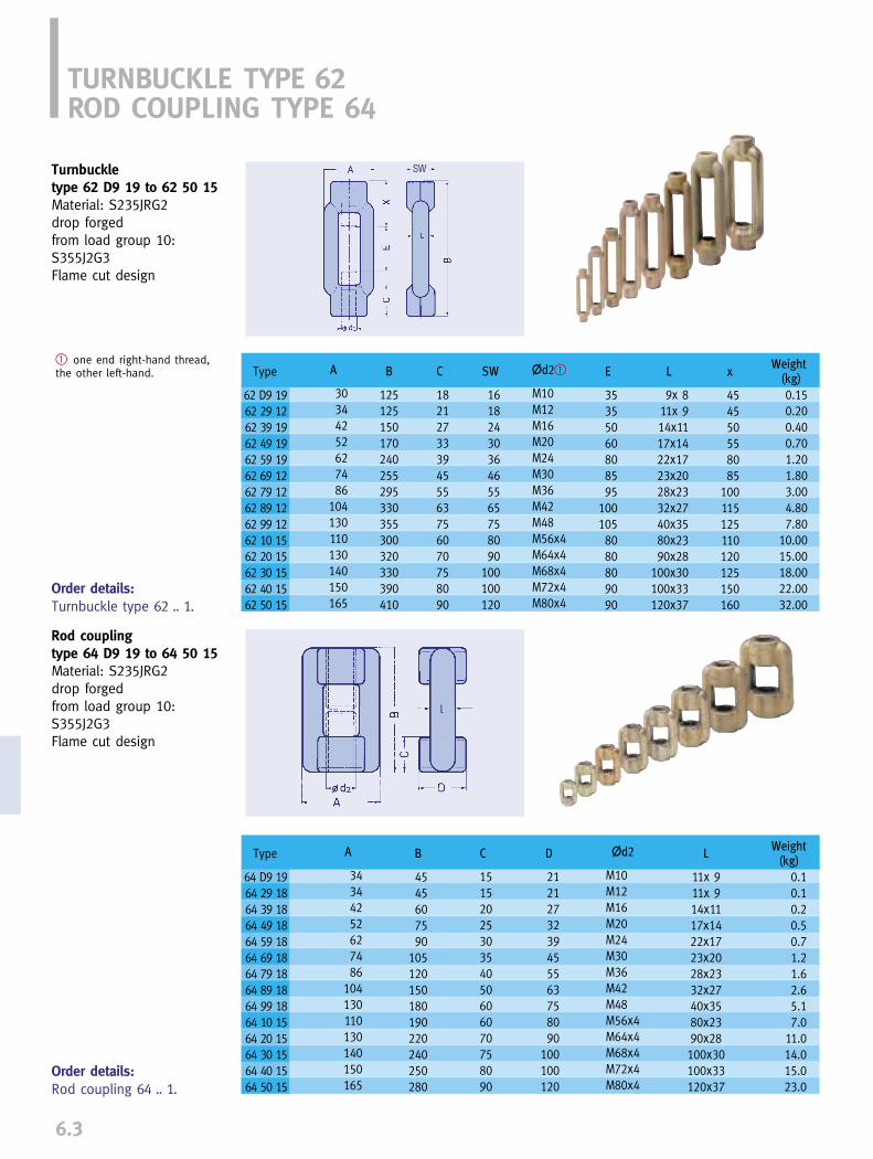
6.3
TURNBUCKLE TYPE 62ROD COUPLING TYPE 64
Turnbuckletype 62 D9 19 to 62 50 15Material: S235JRG2drop forgedfrom load group 10:S355J2G3Flame cut design
� one end right-hand thread,the other left-hand.
Order details:Turnbuckle type 62 .. 1.
SW
Order details:Rod coupling 64 .. 1.
Rod couplingtype 64 D9 19 to 64 50 15Material: S235JRG2drop forgedfrom load group 10:S355J2G3Flame cut design
Type
62 D9 1962 29 1262 39 1962 49 1962 59 1962 69 1262 79 1262 89 1262 99 1262 10 1562 20 1562 30 1562 40 1562 50 15
A
30344252627486
104130110130140150165
B
125125150170240255295330355300320330390410
C
1821273339455563756070758090
SW
1618243036465565758090
100100120
�d2�
M10M12M16M20M24M30M36M42M48M56x4M64x4M68x4M72x4M80x4
E
35355060808595
1001058080809090
L
9x 811x 914x1117x1422x1723x2028x2332x2740x3580x2390x28
100x30100x33120x37
x
454550558085
100115125110120125150160
Weight(kg)
0.150.200.400.701.201.803.004.807.80
10.0015.0018.0022.0032.00
Type
64 D9 1964 29 1864 39 1864 49 1864 59 1864 69 1864 79 1864 89 1864 99 1864 10 1564 20 1564 30 1564 40 1564 50 15
A
34344252627486
104130110130140150165
B
4545607590
105120150180190220240250280
C
1515202530354050606070758090
D
2121273239455563758090
100100120
�d2
M10M12M16M20M24M30M36M42M48M56x4M64x4M68x4M72x4M80x4
L
11x 911x 914x1117x1422x1723x2028x2332x2740x3580x2390x28100x30100x33120x37
Weight(kg)
0.10.10.20.50.71.21.62.65.17.0
11.014.015.023.0

CONNECTING RODSTYPE 63 TO 67
6.4
constant hanger. The longer one is the fit-ting length and can be cut on site accordingto installation length.
Standard lengthsIn general, larger tolerance ranges in thebuilding structure of plants frequently leadto problems when lengths cut to measurefor the connecting rods are used; they oftenprove to be too short. Offering more flexibilityin application, connecting rods in standardlengths have come into increasing use.Fitting can be simply carried out with hang-ing rods already mounted at the upper end.Awkward measurement involving the risk oferrors is thereby avoided. Structural toleran-ces can be favorably compensated.
Length adjustmentTie rods type 65 with left/right hand threadsare always used together with turnbuckletype 62 and form standard lengths. They aredesigned for length adjustment and load-actuated presetting of load chains. All otherthread connections are exclusively right-hand and have to be locked using hexagonnut type 63.
Corrosion protectionAll rods are electrogalvanized as standard(coat thickness 15µm, chromatized yellowfor metric and white for UNC standards).Hot dip galvanizing is available on request.
CertificationMaterial certification can be supplied for allcomponents on request.
Piping systems are embedded in load chainswhere connecting rods form an indispensablecomponent. When selecting them, specialattention must be paid to quality to preventthese seemingly simple units from becom-ing the weakest link in the chain. Decisivefactors for their loading capacity are, besideadequate dimensions, material quality anddesign.
ApplicationsThreaded rods and tie rods connect supportcomponents to each other to bridge instal-lation heights. In conjunction with connec-ting components they can be used as rigidsupports, and in elastic load chains can beused with spring and constant hangers.
Materials and loadingsFor the attachment rods, only materials withguaranteed mechanical properties, with goodhomogeneity and sufficient cold ductility areused. The permissible loads correspond tothe load sufficient table for statically definedcomponents (see Technical specificationspage 0.5).
Rolled threadsAll threads are manufactured using a rollingprocess. Thread rolling does not sever mil-ling fibres as in thread cutting. By means ofthis thread rolling process the material ismade to flow and thereby plastically formed.In this way, additional strengthening of thesurface is achieved, free of notches and offering high surface quality.
In this way, frictional resistance is reduced, with a favorable effect on theadjustment of the rods under loading. In addition, additional reserves for thebending and tensile strength propertiesresult from this by comparison with thedesign calculations.
TypesFully threaded rods type 67 up to M48 andtie rods type 66 (from M20) are available in500mm length increments from 500mm upto 3000mm. Tie rods are threaded 300mmat one end and 600mm at the other. The shorter thread is for adjustment and,for example, for connection to a variable or
Special advantages:
➜ materials with guaranteed properties
➜ rolled threads
➜ notch-free surfaces
➜ electrogalvanized finish
➜ standard lengths
➜ in-house manufacture
6
Manufacturing process for threadedrods.

Order details:Tie rod LR type 65 .. 1.
Tie rod left/right type 65 D1 19 to 65 50 13Material:M10 - M16: S235JRG2from M20: S355JO
LISEGA threaded rod shouldonly be replaced in kind
TIE ROD LR, TYPE 65STUD BOLT, TYPE 67HEXAGON NUTS, TYPE 63
6.5
right left
Stud bolttype 67 D1 19 to 67 91 13Material:M10 - M16: S235JRG2from M20: S355JO
LISEGA threaded rod should only be replaced in kind
Order details:Stud bolt type 67 .. 1.
Hexagon nuttype 63 D9 29 to 63 50 28Material: grade 8Hexagon nuts as counternuts for tie rods and threadedrods M10 to M80x4.
Order details:Hexagon nuttype 63 .. 2.
L
303550607590
110125145
Weight(kg)
0.020.030.070.120.220.420.751.171.77
�d2
M10M12M16M20M24M30M36M42M48
Type
67 D1 1967 21 1367 31 1367 41 1367 51 1367 61 1367 71 1367 81 1367 91 13
Type
63 D9 29 63 29 2863 39 2863 49 2863 59 2863 69 2863 79 2863 89 2863 99 2863 10 2863 20 2863 30 2863 40 2863 50 28
Size
M10M12M16M20M24M30M36M42M48M56x4M64x4M68x4M72x4M80x4
Weight(kg)
0.010.020.030.060.110.220.390.650.981.401.902.252.603.40
Type
65 D1 1965 21 1365 31 1365 41 1365 51 1365 61 1365 71 1365 81 1365 91 1365 10 1365 20 1365 30 1365 40 1365 50 13
�d
8.7510.7414.5418.2021.8527.5533.1538.9144.5353.2261.2065.2069.2077.20
�d2
M10M12M16M20M24M30M36M42M48M56x4M64x4M68x4M72x4M80x4
L
250250250250350350350450450550550550600600
Weight(kg)
0.10.20.30.51.01.62.44.25.59.6
12.714.417.722.1
L1right
80808080
120120120160160200200200220220
L2left
130130130130190190190220220270270270300300

6
6.6
TIE ROD, TYPE 66THREADED ROD, TYPE 67
Material: M10 - M16: S235JRG2from M20: S355JO
LISEGA threaded rod shouldonly be replaced in kind
Order details:Threaded rod / Tie rodtype ...
(at M56x4:)Threaded rod / Tie rod type ...L = ... L1= ...L2= ...
Threaded rod type 67
Tie rod type 66
Connecting rods fromM56x4 upwards can beordered both as threadedrods type 67 or as tie rodstype 66 with individualrolled thread lengths.
� L = max 6000mm, longer lengths on request
�
�
L1 L2
Standard lengths avoidproblems from undersizedinstallation lengths andallow flexibility by cuttingto length on site if required.
Weight(kg/m)
0.50.71.32.02.94.76.89.3
12.2
100067 D3 1967 23 1367 33 1367 43 1367 53 1367 63 1367 73 1367 83 1367 93 13
150067 D4 1967 24 1367 34 1367 44 1367 54 1367 64 1367 74 1367 84 1367 94 13
200067 D5 1967 25 1367 35 1367 45 1367 55 1367 65 1367 75 1367 85 1367 95 13
250067 D6 1967 26 1367 36 1366 46 1366 56 1366 66 1366 76 1366 86 1366 96 13
300067 D7 1967 27 1367 37 1366 47 1366 57 1366 67 1366 77 1366 87 1366 97 13
Type at L=
Type
(L / L1 / L2 please note at order)
50067 D2 1967 22 1367 32 1367 42 1367 52 1367 62 1367 72 1367 82 1367 92 13
�d2
M 10M 12M 16M 20M 24M 30M 36M 42M 48
Weight(kg/m)
17.523.126.229.536.8
�d2
M 56x4M 64x4M 68x4M 72x4M 80x4
66 10 1366 20 1366 30 1366 40 1366 50 13
67 10 1367 20 1367 30 1367 40 1367 50 13
600300

STRUCTURAL ATTACHMENT ELEMENTS
PRODUCT GROUP
7
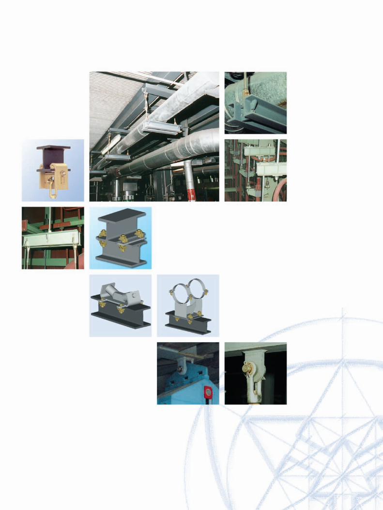

Structural attachments, trapezes ____________________________________ 7.1
Weld-on clevis type 73____________________________________________ 7.2
Weld-on eye plate type 75 ________________________________________ 7.2
Weld-on plate with spherical washer type 74 ________________________ 7.3
Beam clamp type 78 ____________________________________________ 7.4
Trapeze type 79__________________________________________________ 7.4
Beam adapter type 76 ____________________________________________ 7.7
0
1
2
3
4
5
6
8
9
0
1
2
3
4
5
6
8
9
PRODUCTGROUP
7.0
STRUCTURAL ATTACHMENTS,TRAPEZES
CONTENTS PAGE
7
7

7.1
Product Group 7As well as trapezes, the components ofProduct Group 7 include attachment elementsconnecting directly to the structure, such astrapezes.
The permissible loads correspond with theload table for statically determined compo-nents on page 0.5 of the TechnicalSpecification.
For weld-on clevis type 73 and weld-on eyeplate type 75, the minimum weld thicknessesmust be considered. These are designed insuch a way that the maximum weld stressesdo not exceed 75N/mm2 during normal operating conditions.
The stress analysis is based on a loadapplied conically at under 6° angulation.
The weld-on clevis type 73 is particularlysuited for attachment to hollow sections.
The beam clamp type 78 is designed forunwelded on site attachment. The beamwidth is to be specified when ordering.
Trapeze types 79 are suitable for use withclamp base type 49 and can be used asrigid hangers or in conjunction with variableand constant hangers.
For protection against corrosion, the com-ponents are coated with a weldable primer(30µm) or electrogalvanized and then yel-low chromatized (zinc thickness 15µm).The trapeze sections are coated to the LISEGAstandard.
Material certification can be supplied for allcomponents on request.
STRUCTURAL ATTACHMENTS, TRAPEZESPRODUCT GROUP 7
Standardized connecting parts
The attachment of pipesupports to the load bear-ing structure is producedby means of special com-ponents to be welded orclamped. The safety of theconnections depends ontheir adaptation to the prevailing situation andtheir particular suitabilityin each case.
Type 75
Type 78
Type 74
Type 73
Type 76
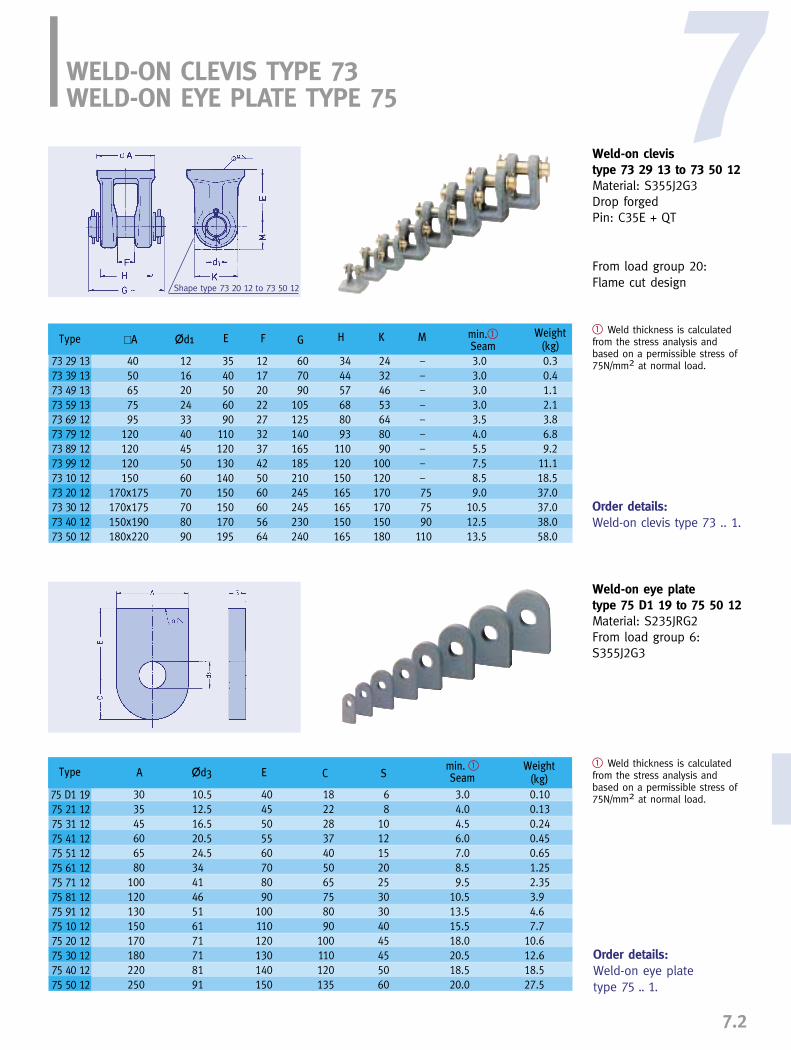
7
7.2
WELD-ON CLEVIS TYPE 73WELD-ON EYE PLATE TYPE 75
Weld-on clevistype 73 29 13 to 73 50 12Material: S355J2G3Drop forgedPin: C35E + QT
From load group 20:Flame cut design
Order details:Weld-on clevis type 73 .. 1.
� Weld thickness is calculatedfrom the stress analysis andbased on a permissible stress of75N/mm2 at normal load.
Shape type 73 20 12 to 73 50 12
Order details:Weld-on eye plate type 75 .. 1.
Weld-on eye plate type 75 D1 19 to 75 50 12Material: S235JRG2From load group 6:S355J2G3
� Weld thickness is calculatedfrom the stress analysis andbased on a permissible stress of75N/mm2 at normal load.
�d1�A E F G H K M Weight(kg)
min.�Seam
Type
73 29 1373 39 1373 49 1373 59 1373 69 1273 79 1273 89 1273 99 1273 10 1273 20 1273 30 1273 40 1273 50 12
�d3A E C SWeight
(kg)min. �Seam
Type
75 D1 1975 21 1275 31 1275 41 1275 51 1275 61 1275 71 1275 81 1275 91 1275 10 1275 20 1275 30 1275 40 1275 50 12
4050657595
120120120150
170x175170x175150x190180x220
12162024334045506070708090
12172022273237425060605664
3540506090
110120130140150150170195
607090
105125140165185210245245230240
344457688093
110120150165165150165
24324653648090
100120170170150180
–––––––––757590
110
0.30.41.12.13.86.89.2
11.118.537.037.038.058.0
3.03.03.03.03.54.05.57.58.59.0
10.512.513.5
303545606580
100120130150170180220250
10.512.516.520.524.5344146516171718191
4045505560708090
100110120130140150
18222837405065758090
100110120135
68
101215202530304045455060
0.100.130.240.450.651.252.353.94.67.7
10.612.618.527.5
3.04.04.56.07.08.59.5
10.513.515.518.020.518.520.0
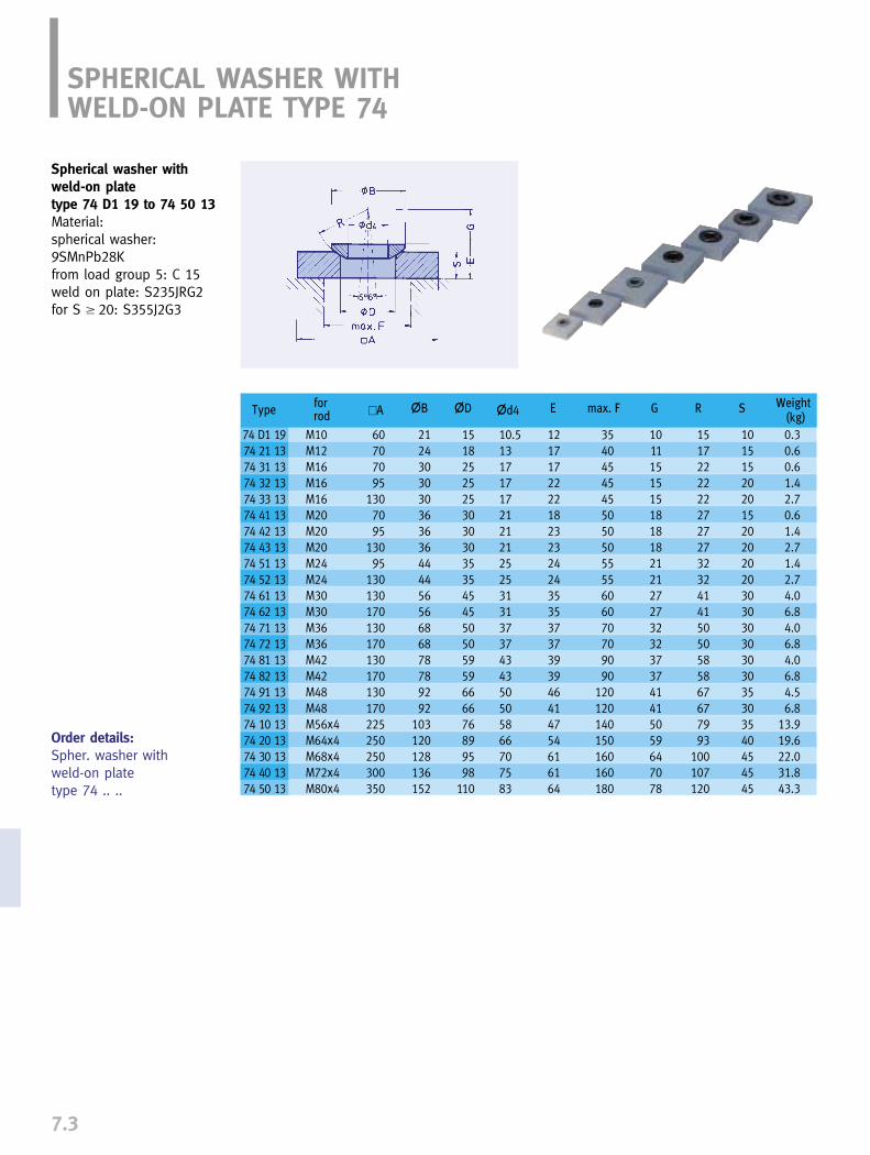
7.3
SPHERICAL WASHER WITH WELD-ON PLATE TYPE 74
Spherical washer withweld-on platetype 74 D1 19 to 74 50 13Material:spherical washer:9SMnPb28Kfrom load group 5: C 15weld on plate: S235JRG2for S � 20: S355J2G3
Order details:Spher. washer with weld-on platetype 74 .. ..
�d4�A �D max. FE�B G R S Weight(kg)
for rod
Type
74 D1 1974 21 1374 31 1374 32 1374 33 1374 41 1374 42 1374 43 1374 51 1374 52 1374 61 1374 62 1374 71 1374 72 1374 81 1374 82 1374 91 1374 92 1374 10 1374 20 1374 30 1374 40 1374 50 13
M10M12M16M16M16M20M20M20M24M24M30M30M36M36M42M42M48M48M56x4M64x4M68x4M72x4M80x4
60707095
1307095
13095
130130170130170130170130170225250250300350
212430303036363644445656686878789292
103120128136152
15182525253030303535454550505959666676899598
110
10.513171717212121252531313737434350505866707583
1217172222182323242435353737393946414754616164
35404545455050505555606070709090
120120140150160160180
1011151515181818212127273232373741415059647078
1517222222272727323241415050585867677993
100107120
1015152020152020202030303030303035303540454545
0.30.60.61.42.70.61.42.71.42.74.06.84.06.84.06.84.56.8
13.919.622.031.843.3
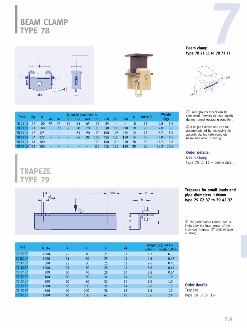
7.4
Beam clamp type 78 21 11 to 78 71 11
Order details:Beam clamp type 78 .1 11 – beam size…
� Load groups 8 & 9 can beconnected. Permissible load 100kNduring normal operating condition.
� A larger t dimension can beaccommodated by increasing Eoaccordingly. Indicate completebeam size when ordering.
7BEAM CLAMPTYPE 78
Order details:Trapeze type 79 .2 37, L=...
Trapezes for small loads andpipe diameters � 80mmtype 79 C2 37 to 79 42 37
� The permissible center load islimited by the load group of theindividual trapeze (3rd digit of typenumber).
TRAPEZE TYPE 79
� 80
d3 A4655–––––
825570––––
1006570––––�
tmax�sWeight
(kg)
E0 up to beam dim. b=
12565708595––
14065709095––
180758090
105100115
2208590
100115100115
260–
100105130110125
300–
110115140110130
Type
78 21 1178 31 1178 41 1178 51 1178 61 1178 71 11
172125344151
8080
125125180180
81015152020
152025253030
0.8 - 1.62.0 - 3.66.7 - 8.96.8 - 9.5
17.7 - 19.8 18.2 - 20.8
Weight (kg) for L=Lmax E b d4 500mm +/- per 100mm
Type
79 C2 3779 D2 3779 12 3779 12 3779 22 3779 22 3779 32 3779 32 3779 42 3779 42 37
10001000600
1000600
1100600
1200600
1200
25252525303030304040
22252528283232353842
11111111141414141818
1.72.62.63.83.86.06.09.69.6
15.6
0.30.460.460.640.641.01.01.51.52.4
a
40606070708080
100100130

7.5
TRAPEZETYPE 79
Trapezetype 79 22 34 to 79 20 34
Order details:Trapezetype 79 .2 34, L=...
� The permissible center load islimited by the load group of theindividual trapeze (3rd or 3rd and 4th
digit of type number).
� The L max dimension can beextended to 2400mm by reducingthe permissible load by 5% forevery 100mm of extension.
� The trapeze is dimensionallycompatible with other componentsin the LISEGA modular systemwithin the load groups specified.
Order details:Trapezetype 79 .3 39, L=...
Trapezetype 79 23 39 to 79 93 39
� The permissible center load islimited by the load group of theindividual trapeze (3rd digit oftype number).
� The L max dimension 1700mm& 1800mm of type 79 23 39 to79 73 39 can be extended to2400mm by reducing the permis-sible load by 5% for every100mm of extension.
� The trapeze is dimensionallycompatible with other compo-nents in the LISEGA modularsystem within the load groupsspecified.
L max�
17001700900
1800140018001250180014001800125024001800240020001800
E
20202040404040556065708085909595
U
808080
120120140140180180200200260260300300300
B
140140140190190200200230230250250310310350350350
Weight (kg)1000mm
1919193131383854546565
102102129129129
+per 100mm
1.71.71.72.72.73.23.24.44.45.15.17.67.69.29.29.2
Load-�group
D - 4D - 4
3 - 4
4 - 5
5 - 6
6 - 7
6 - 8
7 - 9
8 - 109 - 10
d3
�2121
21
25
34
41
46
51
6161
s
�1010
12
18
20
25
25
30
3030
Type
79 22 3479 32 34
79 42 34
79 52 34
79 62 34
79 72 34
79 82 34
79 92 34
79 10 3479 20 34
L max�
17001700180018001800180024002400
E
40404060656595
120
d3
2121253441465161
U
8080
120140180200260300
B
140140190200230250310350
C
40405060708090
100
s
1010121820252530
Weight (kg)1000mm
191932405668
108138
+per 100mm
1.71.72.73.24.45.17.69.2
Load-�group
D - 4D - 43 - 54 - 65 - 76 - 86 - 97 - 10
Type
79 23 3979 33 3979 43 3979 53 3979 63 3979 73 3979 83 3979 93 39
�110000
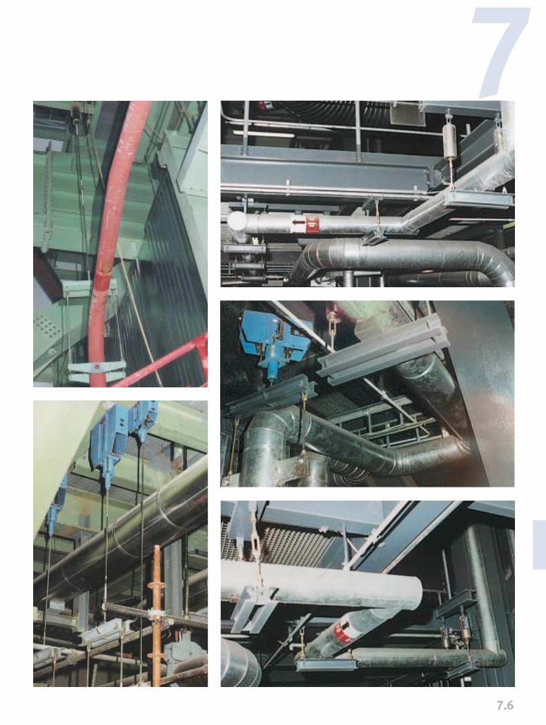
7.6
7

7.7
Beam adapter type 76 D2 11 to 76 42 11
BEAM ADAPTER TYPE 76
For alterations or extensions to pipe systems or structural steel in existing plants, clamp connec-tions are often preferred to wel-ding for the necessary attachmentto the existing structure of pipe supports or additional steel. The use of this method is obligatory when welding is ruled out for safety reasons.The long-lasting security of this type of connection depends essen-tially on the condition of the contactsurfaces and the preset forces applied. For a reliable connection, the specific design of the clamp elements used is decisive.
support load (kN)
2.56.08.5
15.0
Weight (kg)
Bolts 8.8Type
76 D2 1176 22 1176 32 1176 42 11
torque value (Nm) max.
3570
150300
t (clamp thickness)
Order details:Beam adapter type 76 .. 11
�
� The tabulated loads are normal operating loads(load condition H). For emergency (HZ) and faultedloads (HS) see table “Max. permissible loads” on page 0.5
Offering the utmost reliability, LISEGA beamadapters type 76 serve as secure connectionsfor this purpose.
These newly developed components enablethe attachment of diverse components toexisting steel without welding or drilling,while installation is simple and time-saving.LISEGA beam adapters adjust automaticallyon tightening to the thickness of the compo-nent to be clamped. If the given torquevalues are observed, the lasting security ofthe connection is guaranteed. Existing corro-sion protection, e.g. hot-dip galvanizing orcolor coating, is not impaired.
A
48577083
B
24303746
d2
M10M12M16M20
H max
37455465
H min
31384455
min
3466
max
15172025
0.10.20.30.6

7.8
The unique feature of the LISEGA beamadapters is represented by the specialcontact elements. They adjust automaticallydue to their shape to any position and anyexisting sectional flange angles.
The hardened contact elements have a roun-ded grooved profile which presses into thecontact surface on tightening. This providesa form-fit grip which offers mechanical secu-rity against shifting in any direction.
Cross connection:The safe connection of beam sections toeach other is simple effected with an inlayplate and eight LISEGA beam adapters. Theload capacity of a cross connection is givenin the table below.
Cross connection
Interconnection of sections can be made directly or bythe use of a support plate. The load capacity of across connection can be taken from the table on theleft.
Type
76 D2 1176 22 1176 32 1176 42 11
with 4 bolts 8.810243460
Loading capacity (kN)intermed. plate
10121518
Thickness of
Cross connection with LISEGA beam adapters
7Hex. Bolt, Grade 8.8, inclusive Hex. Nut, Grade 8
Bolt-Type
76 D2 11 - 06576 D2 11 - 08076 D2 11 - 10076 22 11 - 07076 22 11 - 09076 22 11 - 12076 32 11 - 09076 32 11 - 12076 32 11 - 15076 42 11 - 12076 42 11 - 15076 42 11 - 180
Dimensions
M10 x 65M10 x 80M10 x100M12 x 70M12 x 90M12 x120M16 x 90M16 x120M16 x150M20 x120M20 x150M20 x180
Weight/kg
0.060.070.080.090.100.120.190.230.270.390.450.51
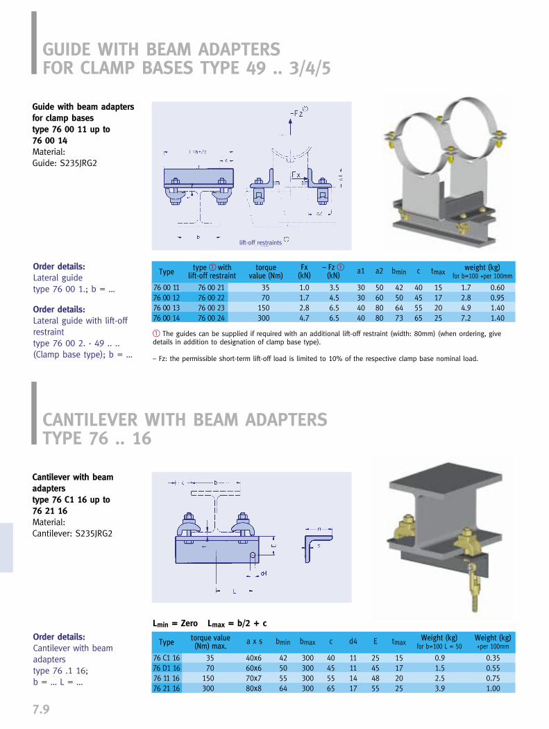
7.9
Guide with beam adaptersfor clamp bases type 76 00 11 up to 76 00 14Material: Guide: S235JRG2
GUIDE WITH BEAM ADAPTERSFOR CLAMP BASES TYPE 49 .. 3/4/5
Order details:Lateral guidetype 76 00 1.; b = …
Order details:Lateral guide with lift-offrestraint type 76 00 2. - 49 .. ..(Clamp base type); b = …
� The guides can be supplied if required with an additional lift-off restraint (width: 80mm) (when ordering, givedetails in addition to designation of clamp base type).
– Fz: the permissible short-term lift-off load is limited to 10% of the respective clamp base nominal load.
Fx (kN)
– Fz �(kN)
type � withlift-off restraint
torquevalue (Nm)
Type
76 00 1176 00 1276 00 1376 00 14
76 00 2176 00 2276 00 2376 00 24
weight (kg)for b=100 +per 100mm
3570
150300
1.01.72.84.7
3.54.56.56.5
a1
30304040
a2
50608080
bmin
42506473
tmax
15172025
1.72.84.97.2
0.600.951.401.40
c
40455565
Cantilever with beamadapterstype 76 C1 16 up to 76 21 16Material:Cantilever: S235JRG2
CANTILEVER WITH BEAM ADAPTERSTYPE 76 .. 16
Order details:Cantilever with beam adapterstype 76 .1 16; b = … L = …
torque value(Nm) max.
Type
76 C1 1676 D1 1676 11 1676 21 16
Weight (kg)+per 100mm
Weight (kg)for b=100 L = 50
3570
150300
a x s
40x660x670x780x8
d4
11111417
bmin
42505564
bmax
300300300300
tmax
15172025
0.91.52.53.9
0.350.550.751.00
c
40455565
E
25454855
Lmin = Zero Lmax = b/2 + c
lift-off restraints

7.10
7
APPLICATION EXAMPLES
Cantilever with beamadaptertype 76 C1 17 up to 76 21 17Material:Cantilever: S235JRG2
CANTILEVER WITH BEAM ADAPTERTYPE 76 .. 17
Order details:Cantilever with beam adaptertype 76 .1 17; b = … L = …
torque value(Nm) max.Type
76 C1 1776 D1 1776 11 1776 21 17
+per 100mm
for b=100 L=100
Lmax up to beam dim. b=82 100 125 140 180 220 260 300
3570
150300
a x s
40x660x670x780x8
d3
11111414
bmin
46556473
120105110145
230170140160
270200170190
310250200235
320280230265
340340290290
360360350310
380380380330
tmax
15172025
1.01.82.84.4
0.350.550.751.00
c
40455565
E
20202525
e
22252830
Clamp base as fixed point
Roller bearing with side plates fitted at works
LISEGA beam adapters can be used in com-bination with all components suitable forseating or flanging on beams. Here are twofurther typical examples with LISEGA stan-dard components:
L � b/2 + c
Weight (kg)

DESIGN DEVELOPMENT TOOLS
PRODUCT GROUP
8LICAD®
EASYSTEEL®
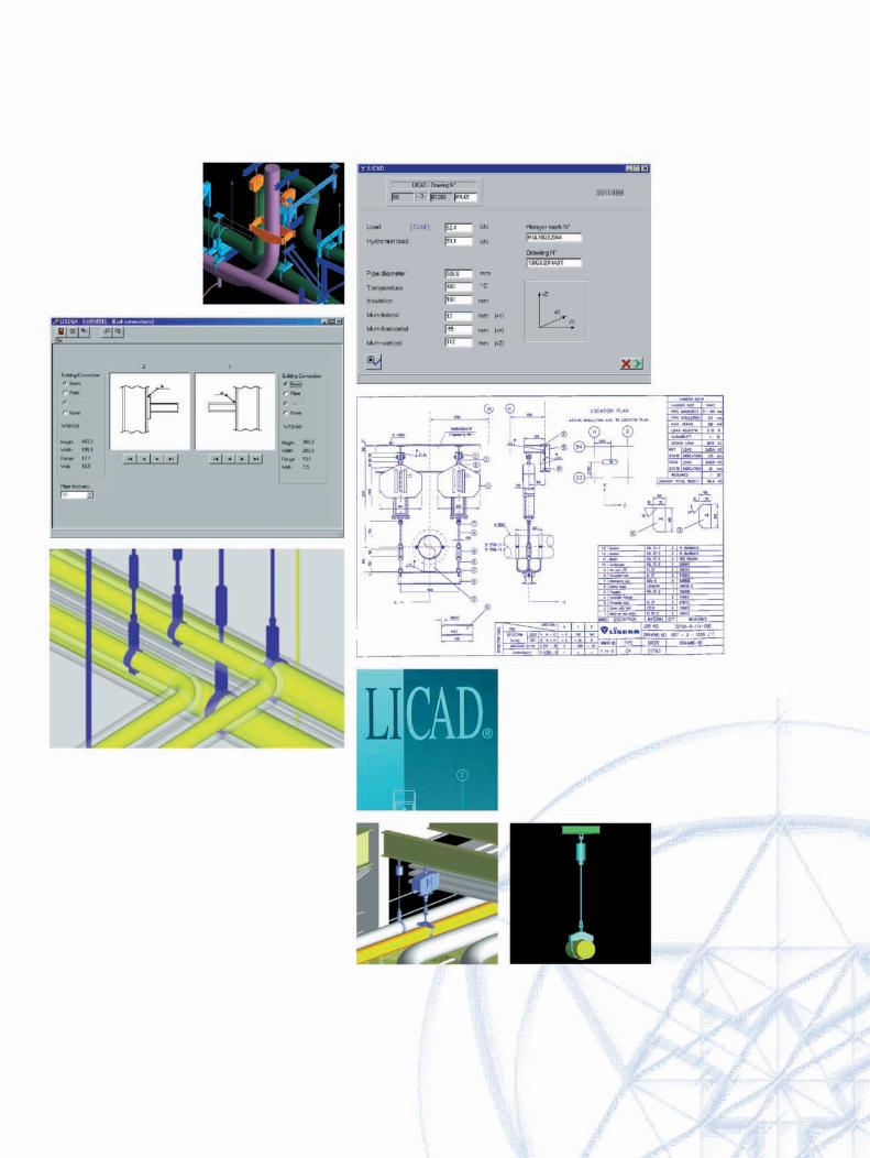

0
1
2
3
4
5
6
7
9
0
1
2
3
4
5
6
7
9
PRODUCTGROUP
8.0
LISEGA DESIGN DEVELOPMENT TOOLS
CONTENTS PAGE
8
8
LISEGA engineering software tools __________________________________8.1
LICAD design program ____________________________________________8.2
EASYSTEEL design program ________________________________________8.5
Component libraries ______________________________________________8.11
Interfaces to CAD programs________________________________________8.11
NAVISWORKS design viewer ______________________________________8.12

8.1
The intelligent solution for support planningLISEGA’s unique modular system was theprerequisite for the creation of highly sophis-ticated user software. The solutions on handopen up new opportunities for increasedengineering design efficiency, improved qualityand significant savings in project manhours.
The general introduction of 2D and 3D CADmodelling has already had a dramatic effecton the design process for pipework systems.However, the benefits for pipe support designhave been limited because supports were notincluded in the 3D CAD programs.
The LICAD® program has set new standards inthis field. It allows the generation of pipe sup-port drawings, bills of materials and 3-Dmodels in minutes rather than hours. LICAD isan intelligent front-end program that providesall the required interface data for all commonCAD software programs from a single source.From the point of view of quality this singlesource function cannot be overemphasised. To exploit further fields of application for
LISEGA DESIGN DEVELOPMENT TOOLS
Via the export function, the support designs can be integ-rated into complex 3D views
the LICAD user, LISEGA has also developedsupplementary software. The complete pack-age includes:
➜ LICAD planning and design software for pipe supports
➜ EASYSTEEL design program for secondary steel
➜ import and export interfaces for tables and databases
➜ interfaces with 3D CAD component packages
➜ 2D / 3D libraries for different CAD programs
➜ interfaces to independent 3D viewer programs
➜ Internet communication systems for downloading program updates and transmitting project information including drawings and orders
LICAD®
EASYSTEEL®
LICAD and EASYSTEEL are trademarks of LISEGA GmbH.All other products, fonts and company names mentioned are trademarks or registered trademarks of their respective companies.

8SOFTWARE WITH PROFIT EFFECT
Needed first - designed lastAs a rule, the planning and design of com-plex pipe systems runs through numerousphases of optimization. Inevitably, the designof pipe supports takes place at the end ofthe whole process, and therefore oftencomes too late to ensure prompt delivery.Although the supports are needed on sitebeforehand in order to ensure optimuminstallation of the piping, they lie right atthe end of the planning chain.
At this point, it is even more vital to avoidunnecessary delay. The time factor is now allimportant.
LICAD speeds up the planning processLICAD, the unique LISEGA design programfor pipe supports, sets the highest standardsin efficiency. With LICAD, poring over catalogsand the painstaking preparation of bills ofmaterial can be dispensed with. The designof supports and load chains no longer needsto be configured manually and then drawnup at great expense in time and money.What otherwise takes hours to produce canbe done in minutes electronically - at theclick of a mouse!
Future orientated logisticsVia LICAD, savings in time are possible in the logistics process from planning rightthrough to delivery. For example, if requiredthe LICAD data can be sent directly by acustomer to our main computer system for order processing on thesame day. This fits in well with ever tighterorder schedules!
LICAD
8.2
The latest version is now available as Release 8 in the following languages: English, German, Spanish,Polish, French, Japaneseand Chinese
AutoCAD drawing based on a LICAD design
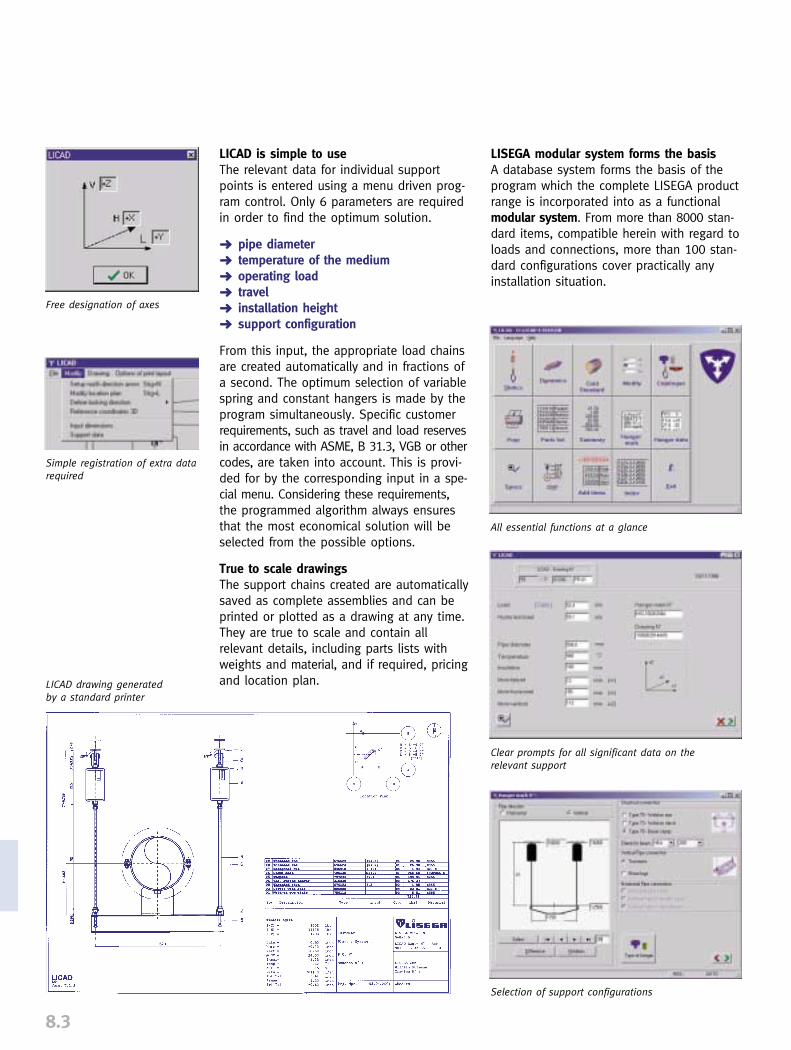
8.3
LICAD is simple to useThe relevant data for individual supportpoints is entered using a menu driven prog-ram control. Only 6 parameters are requiredin order to find the optimum solution.
➜ pipe diameter➜ temperature of the medium➜ operating load➜ travel➜ installation height➜ support configuration
From this input, the appropriate load chainsare created automatically and in fractions ofa second. The optimum selection of variablespring and constant hangers is made by theprogram simultaneously. Specific customerrequirements, such as travel and load reservesin accordance with ASME, B 31.3, VGB or othercodes, are taken into account. This is provi-ded for by the corresponding input in a spe-cial menu. Considering these requirements,the programmed algorithm always ensuresthat the most economical solution will beselected from the possible options.
True to scale drawingsThe support chains created are automaticallysaved as complete assemblies and can beprinted or plotted as a drawing at any time.They are true to scale and contain all relevant details, including parts lists withweights and material, and if required, pricingand location plan.
LISEGA modular system forms the basisA database system forms the basis of theprogram which the complete LISEGA productrange is incorporated into as a functionalmodular system. From more than 8000 stan-dard items, compatible herein with regard toloads and connections, more than 100 stan-dard configurations cover practically anyinstallation situation.
Free designation of axes
Clear prompts for all significant data on the relevant support
Selection of support configurations
All essential functions at a glance
Simple registration of extra datarequired
LICAD drawing generated by a standard printer
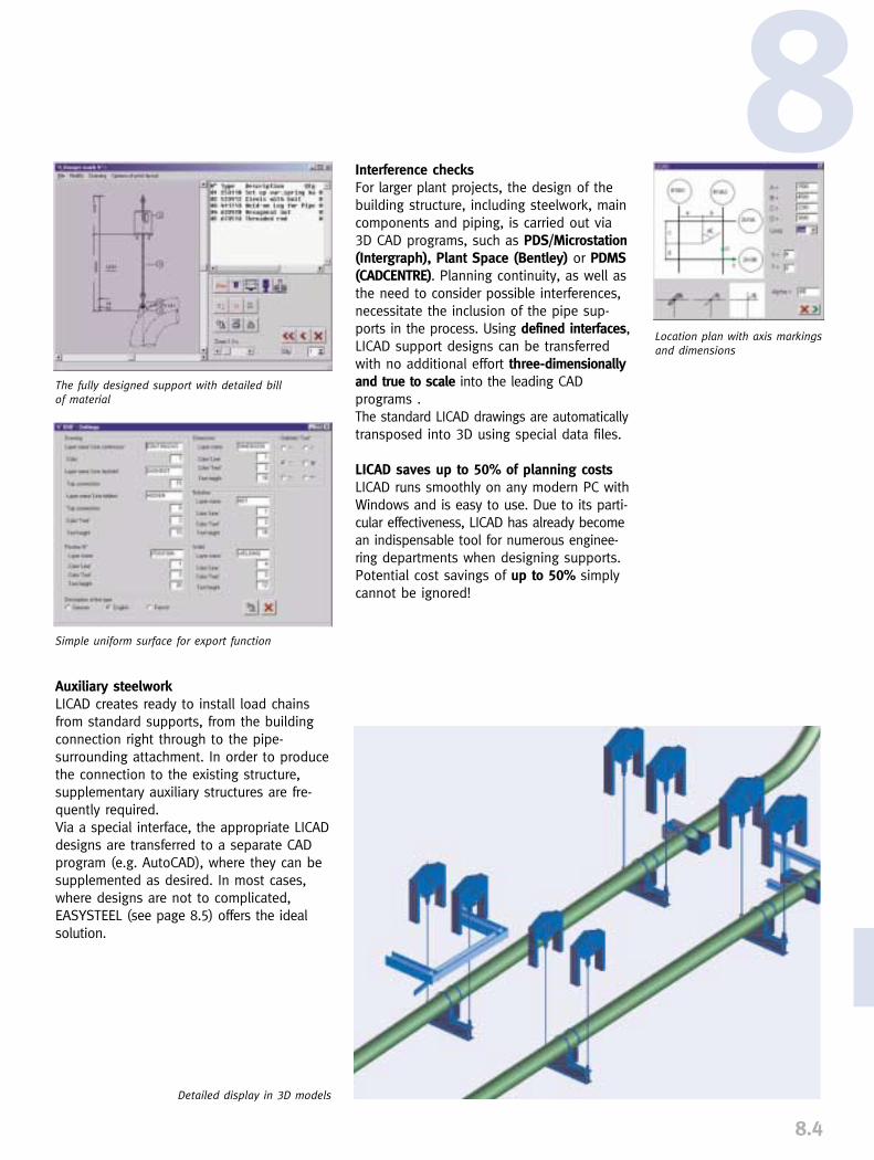
8.4
8Location plan with axis markingsand dimensions
Detailed display in 3D models
Simple uniform surface for export function
The fully designed support with detailed bill of material
Interference checksFor larger plant projects, the design of thebuilding structure, including steelwork, maincomponents and piping, is carried out via3D CAD programs, such as PDS/Microstation(Intergraph), Plant Space (Bentley) or PDMS(CADCENTRE). Planning continuity, as well asthe need to consider possible interferences,necessitate the inclusion of the pipe sup-ports in the process. Using defined interfaces,LICAD support designs can be transferredwith no additional effort three-dimensionallyand true to scale into the leading CAD programs . The standard LICAD drawings are automaticallytransposed into 3D using special data files.
LICAD saves up to 50% of planning costsLICAD runs smoothly on any modern PC withWindows and is easy to use. Due to its parti-cular effectiveness, LICAD has already becomean indispensable tool for numerous enginee-ring departments when designing supports.Potential cost savings of up to 50% simplycannot be ignored!
Auxiliary steelworkLICAD creates ready to install load chains from standard supports, from the buildingconnection right through to the pipe-surrounding attachment. In order to producethe connection to the existing structure,supplementary auxiliary structures are fre-quently required. Via a special interface, the appropriate LICADdesigns are transferred to a separate CADprogram (e.g. AutoCAD), where they can besupplemented as desired. In most cases,where designs are not to complicated, EASYSTEEL (see page 8.5) offers the idealsolution.
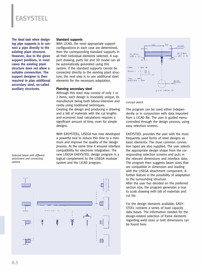
Selected beam with differentattachment and connecting options
EASYSTEEL
8.5
Concept sketch
The ideal task when design-ing pipe supports is to con-nect a pipe directly to theexisting plant structure. However, due to the givensupport positions, in mostcases the existing plantstructure does not allow asuitable connenction. Thesupport designer is thenrequired to plan additionalsecondary steel, so-calledauxiliary structures.
Standard supportsWith LICAD, the most appropriate supportconfigurations in each case are determined,then the corresponding standard supports inall their individual elements selected. A sup-port drawing, parts list and 3D model can allbe automatically generated using thissystem. If the standard supports cannot beconnected directly to the existing plant struc-ture, the next step is to use additional steelelements for the necessary adaptation.
Planning secondary steelAlthough this steel may consist of only 1 or2 items, each design is invariably unique, itsmanufacture being both labour-intensive andcostly using traditional techniques.Creating the design and producing a drawingand a bill of materials with the cut lengthsand economic load calculations requires asignificant amount of time, even for simpledesigns.
With EASYSTEEL, LISEGA has now developeda powerful tool to reduce this time to a mini-mum and improve the quality of the designprocess. At the same time it ensures interfacecompatibility for electronic integration. Thenew LISEGA EASYSTEEL design program is alogical complement to the LISEGA modularsystem and the LICAD program.
The program can be used either indepen-dently or in conjunction with data importedfrom a LICAD file. The user is guided menu-controlled through the design process, usingeasy selection screens.
EASYSTEEL provides the user with the mostfrequently used forms of steel designs asbasic elements. The most common connec-tion types are also supplied. The user selectsthe appropriate design shape from the cor-responding selection screens and puts inthe relevant dimensions and interface data.The program then suggests beam sizes thatare compatible in dimension and loadingwith the LISEGA attachment component. Afurther feature is the possibility of adaptationto the surrounding structure.After the user has decided on the preferredsection size, the program generates a trueto scale drawing with bill of materials andcut list.
For the design elements available, EASY-STEEL contains a series of load capacitydata bases. The information needed for thedesign-related selection of frame elementsregarding weld sizes or bolt dimensions canbe found here.

8.6
8SPEZIAL FEATURES OF THE PROGRAM
Connection of the pipe support to thesecondary steelAll LISEGA standard elements that can beattached to the secondary steel are includedas an option, e. g.:
➜ weld-on eye plates, weld-on clevises,types 73, 75
➜ weld-on brackets, type 35
➜ spherical washers, beam clamps,types 74, 78
➜ clamp bases, type 49
➜ constant hangers with supports, constant supports, types 11+71, type 16
➜ seated spring hangers, spring supports, types 25, 26, 29
➜ U-bolts, type 40
➜ weld-on pipe shoes, stanchions,types 57, 58
➜ roller bearings, types 51, 52, 53
➜ beam adapters, type 76
Available options among the LISEGA standard pipe support connections
Selection screen for support attachment
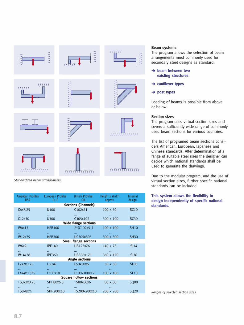
8.7
Beam systemsThe program allows the selection of beamarrangements most commonly used forsecondary steel designs as standard:
➜ beam between two existing structures
➜ cantilever types
➜ post types
Loading of beams is possible from above or below.
Section sizesThe program uses virtual section sizes andcovers a sufficiently wide range of commonlyused beam sections for various countries.
The list of programed beam sections consi-ders American, European, Japanese andChinese standards. After determination of arange of suitable steel sizes the designer candecide which national standards shall beused to generate the drawings.
Due to the modular program, and the use ofvirtual section sizes, further specific nationalstandards can be included.
This system allows the flexibility to design independently of specific nationalstandards.
European ProfilesD, F
British ProfilesGB
American ProfilesUSA
Height x Widthapprox.
Internaldesign.
U100…U300
HEB100…HEB300
IPE140…IPE360
L50x6…L100x10
SHP80x6.3…SHP200x10
C102x51…C305x102
2*(C102x51)…UC305x305
UB127x76…UB356x171
L50x50x6…L100x100x12
TS80x80x6…TS200x200x10
C4x7.25…C12x30
W4x13…W12x79
W6x9…W14x38
L2x2x0.25…L4x4x0.375
TS3x3x0.25…TS8x8x3/8
SC10
SC30
SH10
SH30
SI14
SI36
SL05
SL10
SQ08
SQ20
100 x 50…
300 x 100
100 x 100…
300 x 300
140 x 75…
360 x 170
50 x 50…
100 x 100
80 x 80…
200 x 200
Sections (Channels)
Wide flange sections
Small flange sections
Angle sections
Square hollow sections
Standardized beam arrangements
Ranges of selected section sizes
➡ ➡ ➡
➡
➡
➡
➡
➡ ➡
➡
➡
➡➡
//////
//////
//////
//////
//////////////
/////////////
////////////
/ / / / / /
//////
//////
/ / / / / / / / / / / / / /
/ / / / / / / / / / / / / / // / / / / / / / / / / / / /
//////
/ / / / / / / / / / / / / / /

8.8
8
Weld sizes
Throat thickness 3 5 6 7 9 11 13 mmLeg length 3/16 1/4 5/16 3/8 1/2 5/8 3/4 inch
Options of steel attachment
Attachment to existing structureThe most common techniques for attachment to the existing structure are available in theprogram:
➜ beam directly welded
➜ beam with shim plates or beam with end-plate to spread the load
➜ beam with bolt-on plates
➜ welded clip-angle connections
➜ cut-out flange connection to fit inbetween two beams (with or without end/shim plate)
➜ beam end support on or under a roof girder.
Weld sizes The weld sizes selected by the program areload compatible with the LISEGA modularsystem whether the weld is measured inthroat thickness (mm) or leg length (inch,acc. to American standard).
Connection compatibilityGeometric checks are performed to avoiddesigns which would not fit when assembledon site. These checks include:
1. for welded attachments:
➜ comparison of the width of the attachment(incl. weld seam) with beam width
➜ determination of the weld size suitable for the section and attachment according to prevailing rules and recommendations
2. for bolted connections:
➜ selection of section sizes that allow com-patibility of bolt holes with each other

8.9
How the program worksThe program is database driven, working withload capacity tables to determine the correctsection, bolting and weld sizes. The conceptallows the addition of other national sectionstandards.
Codes and regulationsThe permissible load values used to selectbeam and weld sizes are based on commonlyrecognized steelwork codes such as AISC, BS,DIN. Additionally, user specifications can bedefined and considered during the selectionprocess.
USE OF THE PROGRAM
User inputThe program requires the following inputs:
➜ type designation of the attachment part
➜ operating load acting on the beam
➜ notation of the connection point
This input can be taken directly from theLICAD file.
Four continuous screens guide the user indefining:
➜ positioning of the attachment
➜ the beam system
➜ the necessary length information
➜ the type of connection to surrounding structure
The scaled drawing includes all dimensionsand the bill of material. The weld sizes areshown according to requirements in throatthickness (mm) or leg length (inch). The lan-guage desired can be selected from a rangeof the most common languages.
All relevant data can be entered in one step

8.10
8A logical menu follow up guides the user through the design process

8.11
Component librariesFor further design in the 2D and 3D fields,LISEGA component libraries are available forthe following CAD programs:
➜ AutoCAD, Autodesk➜ PDS, INTERGRAPH➜ PDMS, CADCENTRE➜ SUPPORT MODELER,
Pelican Forge Corp.➜ NAVISWORKS, LightWork Design
The LISEGA catalog items (Standard Supports2010) are available both as text and data-base files.
INTERFACES
2D applicationVia a DFX export file, the support design incl.dimensions can be transferred, with bills ofmaterials, location plans and letter heads asan option, to CAD programs, e.g. AutoCADor MicroStation.
3D applicationVia defined interfaces, the LICAD supportdesigns can be transferred true to scale andwithout additional effort into the leadingCAD programs. Using the component librariesas a basis, the standard CAD drawings canbe converted to 3D in the respective CADprograms. Among others, this is possiblewith:
➜ PDS, INTERGRAPH➜ PDMS, CADCENTRE➜ SUPPORT MODELER, Pelican Forge
Corp.➜ NAVISWORKS, LightWork Design
UpdatesLICAD, EASYSTEEL and other software pack-ages are being constantly updated and ex-panded. The respective valid program ver-sions and interfaces can be downloaded fromthe LISEGA homepage. The necessary licensenumbers are thereby issued to the user viae-mail as an automatic function. Additionalnumbers can also be supplied by phone.
COMPONENT LIBRARIES

8.12
NAVISWORK 3D Design ViewerIn partnership with LIGHTWORK DESIGN inthe UK, LISEGA has created an economicaland easy to utilize 3D design system forpipe supports. NAVISWORKS ROAMER is aproven 3D design review program independentof any CAD design package. It contains all thefunctions that a support designer requires tocheck a 3D plant model, the main featuresbeing:
➜ navigation, communication and interaction in real-time with very large 3D models on a desktop or laptop computer.
➜ interface to MicroStation (incl. PDS) and AutoCAD formats(incl. AutoPlant).
➜ speed and ease in locating key components.
➜ snap-on measuring tool with the ability to copy and paste dimensions into LICAD.
➜ Fast Open GL graphics, enabling the quick and easy real-time navigation and viewing of very large models.
8➜ ease of use – non-CAD-trained staff can
efficiently use the system after minimal training.
➜ interference check (Clash Detector) module available.
➜ export of JPEG and AVI files for transmitting design review information (pictures).
➜ QA enhanced by access to a single model with up to date model description.
➜ lifetime record storage of support information with reduction in lifetime maintenance costs using as-built model.
Users can import 3D plant models fromMicroStation and/or AutoCAD. 3D pipe support models (generated in LICAD)can also be imported. LISEGA customers have the opportunity touse a full working version of the program fora 15 day trial. The program can be installedfrom the LISEGA Multimedia CD. Specimenmodels are also included on the CD. If the program is required for only one pro-ject, a program copy can be obtained throughLISEGA licensed only for this project.
VIEWER

EXTRA SERVICES
SERVICE
9
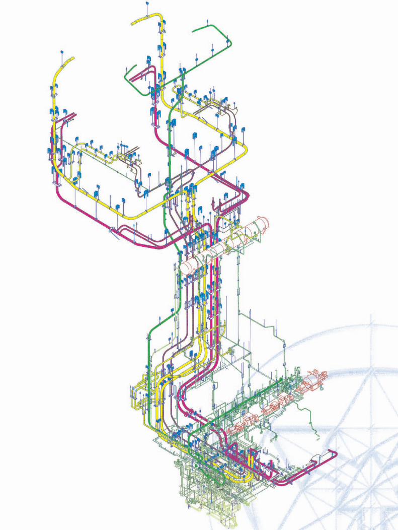

0
1
2
3
4
5
6
7
8
0
1
2
3
4
5
6
7
8
9
PRODUCTGROUP 9
9.0
SERVICES
Supplementary services __________________________________________ 9.1
Engineering______________________________________________________ 9.5
Field service____________________________________________________ 9.11
CONTENTS PAGE

SUPPLEMENTARY SERVICESPRODUCT GROUP 9
9.1
Special fields of application The standard designs described cover theusual range of application. For special areas,e.g. nuclear plants or offshore operations,extended measures in the question of materi-al quality or corrosion protection are requiredoccasionally. The fulfilment of special customerrequirements is guaranteed by the integratedquality assurance system. The applicablecertification is supplied with the order.
Service areasIncreasing pressure from costs through inter-national competition has led to the dispersalof service areas (outsourcing). Following thegrowing demand, LISEGA has readjusted itscapacity in the fields of engineering and onsiteservice at all locations. For support design,the use of specially developed computer soft-ware enables particularly effective support,e.g. in the 3D sector.
Standardized supplementary servicesBy way of specific supplementary services theLISEGA standard program can be adjusted toparticular needs. The field of product applica-tion is widened in this way and the LISEGAperformance package further optimised. Allthe significant supplementary services arestandardized according to the LISEGA modularsystem and cataloged in Product Group 9.
9.0 Supplementary services
9.1 Adjustment workConstant and spring hangers are set andblocked for cold load by electronic forceand travel measurement on a hydraulic testbench.
9.1.1 Storage of blocking devicesIf required, spring hangers can be suppliedwith storage points for blocking devices onthe housing (after deblocking). This is stan-dard on the constant hangers.
The LISEGA product pro-gram introduced in theSTANDARD SUPPORTS2010 catalog correspondsto current technologicaldevelopments in appro-priate supports for pipingsystems in industrial plantconstruction.
The relevant internationalrequirements are satisfiedat the highest level.
9.2 Quality management
9.2.1 Inspection reportsWhen required, inspection reports with digi-tally recorded values can be supplied asfunctional certification for constant andspring hangers and shock absorbers.
9.2.2 In service testingIn service testing for the mechanically func-tioning components of all makes can be carried out in the relevant LISEGA plants oron mobile test benches in the installation itself.
9.2.3 Material certificationThe following material certificates can be supplied on request:
9.2.4 Supplier COCManufacture and dispatch as per order can beconfirmed with a Certificate of Compliance.
9.2.5 Material certificates 2.2The material in all catalog components canbe certified by material certificates accordingto EN 10204 - 2.2 (not in US).
Compilation of component documentation. �

9.2
99.2.6 Material certificates 3.1 B for specialcomponentsComponents affected by the direct flux offorce, e.g. the springs of constant and springhangers, can be supplied with material certi-ficates acc. to EN 10204 - 3.1 B (not in US).
9.2.7 Complete traceability through CMTRThe complete traceability of material for allcatalog product components by way of sepa-rate manufacture is possible acc. to CertifiedMaterial Test Report.
9.2.8 Pre-examination documentsThe standardized products have largely beenqualified through independent authorities(TÜV or VGB) by specified type and suitabilitytests.
For special, particularly non-standardizeddesigns, pre-examination documents such asdesign drawings, parts lists, calculations, testsequence schedules and welding plans canbe supplied.
9.2.9 Stricter quality requirementsFor fields of application with stricter securityand quality requirements, such as nuclearinstallations, the quality assurance programis applied at the highest quality level. All thestages of order processing and handling fol-low recognized procedures corresponding tothe quality requirements of standard codesand guidelines such as KTA or TÜV suitabilitytests, as well as ASME Sect. III, NCA and NF.
The following aspects are particularly consi-dered:
➜ materials acquisition from approved suppliers
➜ complete traceability of material
➜ special supervision of manufacture
All sectors are fully documented.
9.3 Surface treatmentIn addition to specified, standardized surfacetreatment, extended corrosion protectionaccording to Technical Specification, Section 8, page 0.10, can be supplied.
9.3.1 Spring hangers and spring supports upto load group 9In addition to galvanizing, all exterior surfacesof components are treated with a barriercoating, layer thickness 30µm, and a dual-component acrylic-polyurethane blue topcoat,layer thickness 60µm. Total layer thickness:� 100µm
9.3.2 Constant hangers and supports, variablespring hangers from load size 9, rigid strutsand trapezes.In addition to the standard coating, all outersurfaces of components are treated with adual-component acrylic-polyurethane bluetopcoat, coating thickness 60µm. Total layerthickness: � 180µm
9.3.3 Connecting elementsThe connecting elements in Product Group 6can be supplied hot dip galvanized fromstock.
� Immersion painting
Spray painting

9.3
9.3.4 Pipe bearings and pipe clampsPipe-surrounding components can be trea-ted with a special coating on a blasted sur-face.
9.3.5 Special treatmentBesides the above-mentioned processes,other kinds of corrosion protection can beagreed upon for all products. Due to storage-related availability of standard designs,separate manufacture may be required inthis respect. This applies particularly to hotdip galvanizing.
9.4 PreassemblyIf not otherwise agreed, the componentsmaking up a shipment are packaged inbundles according to type.
For easier handling and economical assem-bly on site, individual components canhowever be supplied pre-assembled in loadchains, bundled and marked.
9.4.1 Preassembly of load chainsThe load chains are pre-assembled accor-ding to support drawings and marked withthe support position number. Constant andvariable spring hangers, as well as largerpipe clamps (bulky components), are keptseparate for easier handling and markedaccordingly.
9.4.2 Preassembly of pipe clamps and pipebearingsPipe clamp and pipe bearing halves arebolted together and supplied as completeunits.
9.5. Designation and markingIf not otherwise agreed, the componentsare sorted and packaged according to typeand marked for quantity, type number andorder number. Additional designations andmarkings can be supplied if required.
9.5.1 Designation of individual parts If required, all components can be individu-ally marked as to type, support or ordernumber.
9.5.2 Second name plateVariable spring hangers and constant hangerscan be fitted with a second name plate ifrequired.
9.5.3 Second load and travel scaleConstant and variable spring hangers canbe fitted with a second travel scale andconstant hangers with a second load scaleif required.
9.6 PackagingFor the various packaging requirementsappropriate types of packaging are available:
Load chain assembly
Load chains, preassembled, bundled and marked

9.4
99.6.1 Inland packagingSturdy wooden crates or pallets fitted withskids for fork-lifting are supplied for road orrail transport.
9.6.2 Seaworthy packagingSpecial wooden crates are used with skidsfor fork-lifting and reinforced side walls forcrane operations. The inside of the crate lidis covered with plastic sheeting to preventmoisture ingression.
9.6.3 Further special types of packagingcan be agreed upon in detail.
9.7. TransportIf required, we can take responsibility forthe logistics of shipment of goods to thesite or other destinations (FCA, FOB, etc.)
Part of dispatch section
Seaworthy packaging
Project-related order logistics
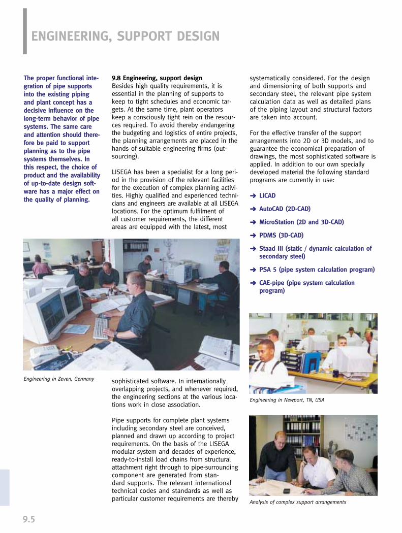
9.5
ENGINEERING, SUPPORT DESIGN
9.8 Engineering, support designBesides high quality requirements, it isessential in the planning of supports tokeep to tight schedules and economic tar-gets. At the same time, plant operatorskeep a consciously tight rein on the resour-ces required. To avoid thereby endangeringthe budgeting and logistics of entire projects,the planning arrangements are placed in thehands of suitable engineering firms (out-sourcing).
LISEGA has been a specialist for a long peri-od in the provision of the relevant facilitiesfor the execution of complex planning activi-ties. Highly qualified and experienced techni-cians and engineers are available at all LISEGAlocations. For the optimum fulfilment of all customer requirements, the differentareas are equipped with the latest, most
sophisticated software. In internationallyoverlapping projects, and whenever required,the engineering sections at the various loca-tions work in close association.
Pipe supports for complete plant systemsincluding secondary steel are conceived,planned and drawn up according to projectrequirements. On the basis of the LISEGAmodular system and decades of experience,ready-to-install load chains from structuralattachment right through to pipe-surroundingcomponent are generated from stan-dard supports. The relevant internationaltechnical codes and standards as well asparticular customer requirements are thereby
Engineering in Zeven, Germany
Engineering in Newport, TN, USA
systematically considered. For the designand dimensioning of both supports andsecondary steel, the relevant pipe systemcalculation data as well as detailed plansof the piping layout and structural factorsare taken into account.
For the effective transfer of the supportarrangements into 2D or 3D models, and toguarantee the economical preparation ofdrawings, the most sophisticated software isapplied. In addition to our own speciallydeveloped material the following standardprograms are currently in use:
➜ LICAD
➜ AutoCAD (2D-CAD)
➜ MicroStation (2D and 3D-CAD)
➜ PDMS (3D-CAD)
➜ Staad III (static / dynamic calculation of secondary steel)
➜ PSA 5 (pipe system calculation program)
➜ CAE-pipe (pipe system calculation program)
Analysis of complex support arrangements
The proper functional inte-gration of pipe supportsinto the existing pipingand plant concept has adecisive influence on thelong-term behavior of pipesystems. The same careand attention should there-fore be paid to supportplanning as to the pipesystems themselves. Inthis respect, the choice ofproduct and the availabilityof up-to-date design soft-ware has a major effect onthe quality of planning.

9.6
9
LICAD drawing
CAD drawing according to customer requirements
The following engineering services are avai-lable according to requirements:
9.8.1 Design of support arrangements (loadchain designs) with LICAD:
The following data should ideally be sup-plied by the customer:
➜ pipe diameter
➜ loads
➜ movements
➜ temperatures
➜ insulation thickness, if necessary
➜ piping material
➜ installation length and position, orcorresponding piping and structural plans
➜ specifications
On the basis of these data, ready-to-installload chains are generated with the LISEGAdesign program LICAD from standard sup-ports, from structural attachment right throughto pipe-surrounding component. The designsso prepared are stored and printed out asscale drawings, including parts lists with loadand material data. As an option, locationplans and pricing details can be included withthe LICAD drawings.
9.8.2 Generation of 2D CAD drawings with-out supplementary steel
For the preparation of 2D CAD drawings thefollowing information on the drawing layout,in addition to the details in 9.8.1, is required:
➜ drawing sheet in format DXF, DWG or DGN
➜ drawing numbers
➜ location plans
As the basis for the CAD drawing, a LICADsupport configuration together with dimensio-ning, parts list and relevant adjustment datais supplied via a special interface. The drawingsheet required is inserted in the customer's
specific drawing layout. The CAD drawing is supplemented by a location plan and drawingnumber.

9.7
9.8.3 Generation of 2D CAD drawings incl.supplementary steel
As well as customer details mentioned in9.8.1 and 9.8.2, data as to dimension andposition of the steelwork is required for CADdrawings including supplementary steel(secondary steel). The CAD drawings aregenerated as in 9.8.2 but additionally sup-plemented by the steelwork required.
9.8.4 Complete planning with preparation ofCAD drawingsFor complete support planning (engineering),the following documentation is supplied bythe customer beside the data according to9.8.1:
➜ drawing sheet in format DXF, DWG or DGN
➜ drawing numbers
➜ piping isometrics
➜ piping calculations
➜ pipe plans
➜ structural plans
The planning of the support designs and thesecondary steel required is based on thedocumentation supplied. The results aregenerated as 2D CAD drawings in the AutoCAD program as described in 9.8.2 and 9.8.3.
9.8.5 Preparation of 3D models withMicroStation for PDSFor the generation of 3D models onMicroStation the pipe supports are first pre-pared as 2D models. The 2D data are thentransposed into 3D data by LICAD andtransferred via an interface into theMicroStation 3D model. The secondary steelrequired is supplemented in the 3D model.In PDS the 3D models so generated can beused for interference checks.
CAD drawing with supplementary steel
CAD drawing for complex support situation
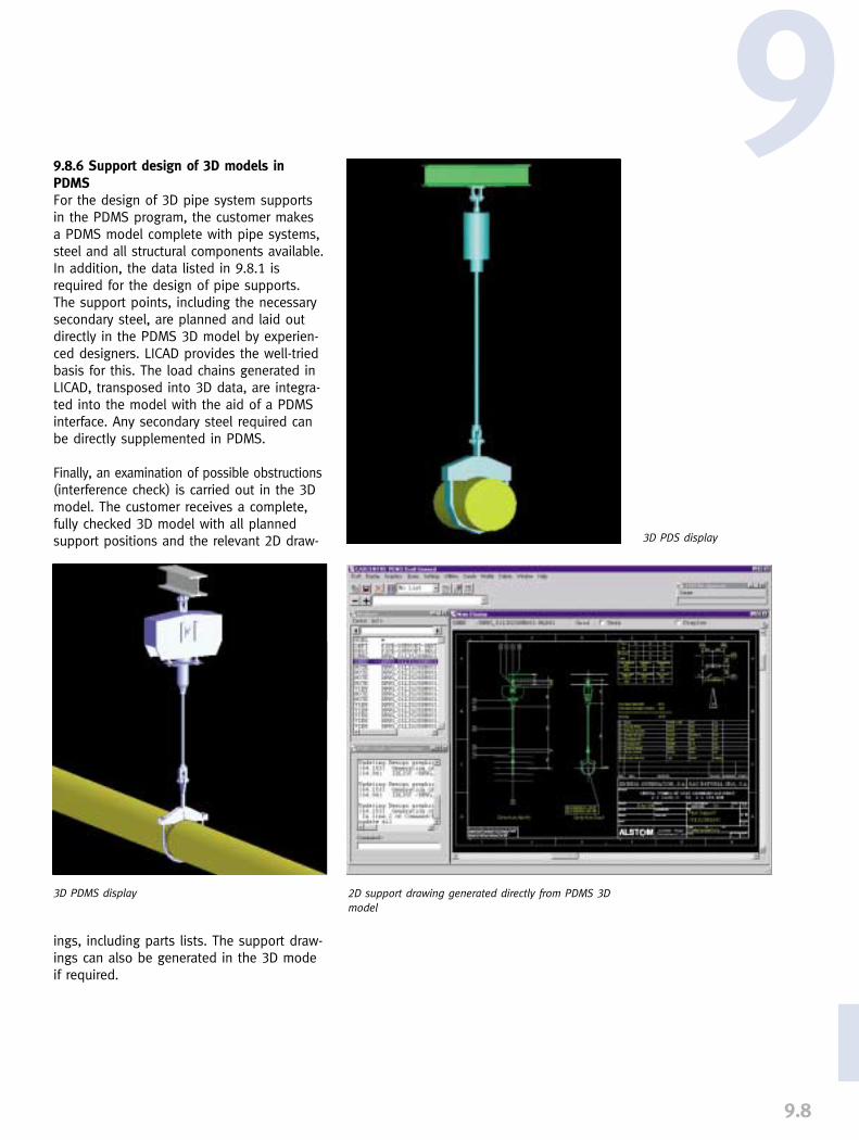
9.8
9
3D PDS display
3D PDMS display
9.8.6 Support design of 3D models inPDMSFor the design of 3D pipe system supportsin the PDMS program, the customer makesa PDMS model complete with pipe systems,steel and all structural components available.In addition, the data listed in 9.8.1 is required for the design of pipe supports.The support points, including the necessarysecondary steel, are planned and laid outdirectly in the PDMS 3D model by experien-ced designers. LICAD provides the well-triedbasis for this. The load chains generated inLICAD, transposed into 3D data, are integra-ted into the model with the aid of a PDMSinterface. Any secondary steel required canbe directly supplemented in PDMS.
Finally, an examination of possible obstructions(interference check) is carried out in the 3Dmodel. The customer receives a complete,fully checked 3D model with all plannedsupport positions and the relevant 2D draw-
ings, including parts lists. The support draw-ings can also be generated in the 3D modeif required.
2D support drawing generated directly from PDMS 3Dmodel

9.9
9.8.7 Static calculation of secondary steelincluding structural attachment loads.LISEGA provides the design report summaryfor the dimensioning of the planned secon-dary steel according to Code AISC orDIN18800.
Design of steelwork with STAAD III
This summary is supplied with the STAAD IIIstatics program.
9.8.8 Pipe system calculation In older installations it is often necessary forreasons of operational safety to renew pipesystems and supports in order to meet cur-rent standards in technology. There is ofteninsufficient documentation available offeringinformation on calculations regarding theoriginal design. If so desired, a static calcu-lation of pipe systems can be provided. Thefollowing typical load conditions per supportpoint are calculated:
➜ weight
➜ temperature
➜ static G
➜ emergency shutdown
➜ hydrostatic test
The codes ASME B31.1, ASME B31.3 andBS806 are observed for the calculations. Therelevant code is to be defined on orderingaccording to version and year.
SUPPORT REACTIONS IN KNS METER
KNT. LOADCASE X FORCE Y FORCE
STATIC SYS. = SPACE
Z FORCE X MOM. Y MOM. Z MOM.

9.10
9
2D support drawings and PDS 3D modelgenerated from them
The following advantages are available to the customer whenusing LISEGA planning capacity to the fullest:
➜ economical limitation of your own capacity
➜ complete certainty of expert performance by experienced specialists
➜ fast and flexible processing of whole project from initial order through to delivery on the principle of “everything under one roof”
➜ complete and lasting computerized documentation
➜ availability of highly skilled personnel for any subsequent services required

9.11
ON SITE SERVICE
9.9 Plant serviceAdditional stress and strain caused by low-quality pipe supports during pipe systemoperation can lead to long-term damagethat considerably increases the risk of mal-function and breakdown when the plant isin operation.
Faults frequently occurring in pipe supportsare:
➜ poor support designs
➜ faulty installation
➜ incorrect load settings
➜ inappropriate instructions
➜ deficient quality of support components
A particular problem often arises in olderinstallations when variable spring and con-stant hangers are installed with springs thatare not pre-relaxed (see page 1.16 in thisrespect). Through the increasing relaxationover a period of time a growing loss of ulti-mate load gradually occurs. Load deviationsresulting from this can lead to impermissibleadditional stress in sensitive areas, e.g. atconnection points. Timely inspection in theplant can contribute to the prompt identifi-cation and elimination of critical stresses.
The operational safety ofpipe systems and thereforethe availability and longlife of the plants is depen-dent to a large degree onthe condition and functionalcapacity of the supportsemployed.
To avoid costly damageand operational breakdownthe regular inspection ofthermal movement inpiping systems and thecondition of supports -especially in older installa-tions - is urgently advised.
Specimen of a hanger check listfrom a plant
Checking piping movements
For this special service LISEGA offers theresources of an internationally leadingmanufacturer maintaining a team of quali-fied and experienced specialists at all grouplocations.
This team inspects the thermal movement inthe piping system and checks the supportsystems. They produce comprehensivereports and provide the appropriate recom-mendations for a solution. Special softwareis implemented for the presentation anddocumentation of findings.
The service team is expressly trained for theexecution of specific services in the field ofpipe supports and works strictly accordingto the guidelines laid down by qualitymanagement and the relevant safety stan-dards.
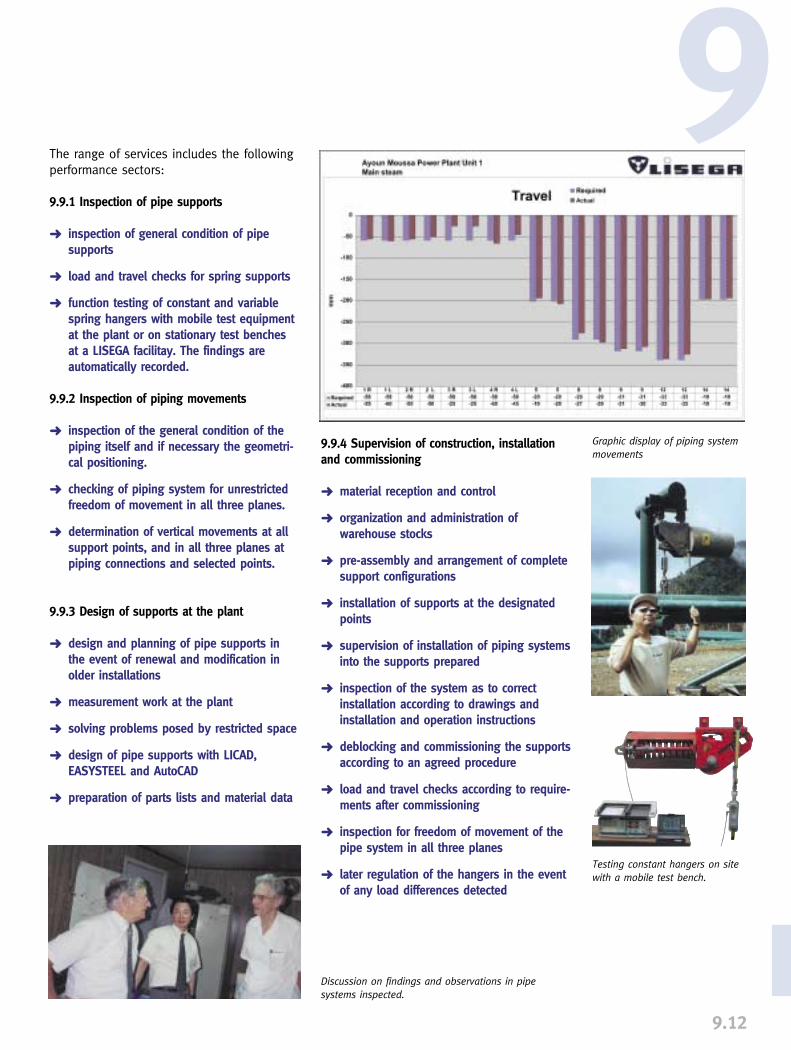
9.12
9
Graphic display of piping systemmovements
Discussion on findings and observations in pipesystems inspected.
Testing constant hangers on sitewith a mobile test bench.
The range of services includes the followingperformance sectors:
9.9.1 Inspection of pipe supports
➜ inspection of general condition of pipe supports
➜ load and travel checks for spring supports
➜ function testing of constant and variable spring hangers with mobile test equipment at the plant or on stationary test benches at a LISEGA facilitay. The findings are automatically recorded.
9.9.2 Inspection of piping movements
➜ inspection of the general condition of the piping itself and if necessary the geometri-cal positioning.
➜ checking of piping system for unrestricted freedom of movement in all three planes.
➜ determination of vertical movements at all support points, and in all three planes at piping connections and selected points.
9.9.3 Design of supports at the plant
➜ design and planning of pipe supports in the event of renewal and modification in older installations
➜ measurement work at the plant
➜ solving problems posed by restricted space
➜ design of pipe supports with LICAD, EASYSTEEL and AutoCAD
➜ preparation of parts lists and material data
9.9.4 Supervision of construction, installationand commissioning
➜ material reception and control
➜ organization and administration of warehouse stocks
➜ pre-assembly and arrangement of completesupport configurations
➜ installation of supports at the designated points
➜ supervision of installation of piping systemsinto the supports prepared
➜ inspection of the system as to correct installation according to drawings and installation and operation instructions
➜ deblocking and commissioning the supportsaccording to an agreed procedure
➜ load and travel checks according to require-ments after commissioning
➜ inspection for freedom of movement of the pipe system in all three planes
➜ later regulation of the hangers in the event of any load differences detected

➜ function testing after dismounting and documentation of results
➜ dismounting of shock absorbers and inspection of individual components for wear or damage
➜ exchange of all seals and hydraulic fluidas well as other components with noticeable wear
➜ final function testing in line with test program and according to relevant specifications
➜ reinstallation at the plant
➜ preparation of complete final documen-tation
The LISEGA on-site service spectrumapplies especially to the use of pipe sup-ports and their effect on pipe systems. Oncorresponding utilization, the LISEGA servicepackage provides a valuable contributionto the functional safety and long life ofcomplex pipe systems.
9.13
9.9.5 Maintenance, inspection and checkingof shock absorbers
➜ visual inspection to identify signs of possible functional disorders
➜ function testing on mobile benches at the plant or on corresponding testing facilities at the works
➜ installation and dismounting, with sub-sequent transportation to the testing facilities
➜ the function testing with corresponding electronic documentation of findings can be carried out for all makes
9.9.6 Servicing of shock absorbers afterlengthy operational use or after overloa-ding
➜ dismounting of shock absorbers and documentation of external state and environmental conditions
Testing PSA shock absorbers atthe plant with a mobile LISEGAtest bench.
Check on correct installation Supervision of support installation