list of experiments (cycle-2) -...
TRANSCRIPT

S5 DC Machines Lab Manual
Department of Electrical & Electronics Engineering, MEAEC
List of Experiments
(Cycle-2)
SL.No Experiment
1 HOPKINSON’S TEST
2 RETARDATION TEST
3 SEPARATION OF LOSSES IN A SINGLE PHASE
TRANSFORMER
4 SEPERATION OF LOSSES IN A DC SHUNT MACHINE
5 SUMPNER’S TEST

S5 DC Machines Lab Manual
Department of Electrical & Electronics Engineering, MEAEC
Experiment No:1 HOPKINSON’S TEST
AIM
1. To conduct Hopkinson’s test or Regenerative Test or Back to back test on a pair of
DC shunt machine and hence predetermine the efficiency of the machine working as
a motor and generator under various load conditions.
2. Draw Output Vs Efficiency graph (as a motor and as a generator).
APPARATUS REQUIRED
PRINCIPLE
This is a regenerative test and is also known as back to back test which can be carried
out on two identical DC shunt machine. The two machines are mechanically coupled and so
adjusted electrically that one of them act as motor and the other as generator. The motor
supplies mechanical power to drive the generator while the generator supplies electrical power
to the motor. The power drawn from supply mains is only to meet losses of the two machines.
Calculation of efficiency
Let field currents of the machines be are so adjusted that the second machine is acting
as generator and the first machine is acting as motor. Also let us assume the current drawn
from the supply be I1. Total power drawn from supply is VI1 which goes to supply all the
losses (i.e. Cu losses in armature & field and rotational losses) of both the machines,
Now:
Input from supply = V(I1+I3+I4)
Armature Cu losses in motor= (I1 + I2)2 * Ram
Sl. No: Apparatus Specification* Quantity
1 Voltmeter 0-300 V, MC
0-600V , MC
1
1
2 Ammeter
0-30A, MC
0-10A.MC
0-2A, MC
2
1
2
3 Rheostat 1000 Ω, 1 A
272 Ω, 1.7 A
1
1
4 Tachometer 1

S5 DC Machines Lab Manual
Department of Electrical & Electronics Engineering, MEAEC
Armature Cu losses in generator= I22Rag
Field copper loss in motor = VI3
Field copper loss in generator = VI4
∴ Rotational losses of both the machines, Ws = Input – Total copper loss
= V(I1+I3+I4) – (I1 + I2)2 * Ram - I2
2 Rag - VI3 - VI4
Hence stray loss per machine, W0 = Ws/2
Since speed of both the machines are same, it is reasonable to assume the rotational
losses of both the machines are equal; which is strictly not correct as the field current of the
generator will be a bit more than the field current of the motor.
Efficiency of the motor
As pointed out earlier, for efficiency calculation of motor, first calculate the input
power and then subtract the losses to get the output mechanical power as shown below,
Motor input =VI5
Armature Cu losses in motor= (I1 + I2)2 * Ram
Field copper loss in motor = VI3
Total losses in motor= W0 + (I1+I2)2 * Ram+ VI3
Motor output = Motor input - Total losses in motor
= V I5 - W0 - (I1+I2)2
* Ram- VI3
Motor efficiency = Output / Input
Efficiency of the generator
For generator start with output power of the generator and then add the losses to get
the input mechanical power and hence efficiency as shown below,
Generator Output = VI2
Armature Cu losses in generator= I22Rag
Field copper loss in generator = VI4
Generator total losses = W0 + I22Rag + VI4
Generator input = Generator Output+ Generator total losses
= VI2 + W0 + I22Rag + VI4

S5 DC Machines Lab Manual
Department of Electrical & Electronics Engineering, MEAEC
Generator efficiency = Output / Input
The following are the advantages and disadvantages of Hopkinson’s test.
Advantages:
1. The power required for conducting the test is small compared to full load
powers of the two machines.
2. Since the machines are operated at full load condition, change in iron loss due
to distortion in flux at full load will be included in the calculations.
3. As the machines are tested under full load conditions, the temperature rise and
quality of commutation of the two machines can be observed.
4. The test is economical as the power required for the test is very small which is
just sufficient to meet the losses.
5. There is no need for arranging any actual load. Similarly by changing the field
currents of two machines, the load can be easily changed and a load test over
complete range of load can be taken.
Disadvantages:
1. There is difficulty in availability of two identical machines.
2. The iron losses in the two machines cannot be separated. The iron losses are
different in both the machines because of different excitations.
3. The machines are not loaded equally in case of small machines which may lead
to difficulty in analysis.

S5 DC Machines Lab Manual
Department of Electrical & Electronics Engineering, MEAEC
CIRCUIT DIAGRAM
MEASUREMENT OF ARMATURE RESISTANCE
PROCEDURE
1. Connect the circuit as shown in the circuit diagram.
2. Keep the field rheostat of the motor at minimum and that of generator at maximum
position.

S5 DC Machines Lab Manual
Department of Electrical & Electronics Engineering, MEAEC
3. Keep the SPST switch in open condition.
4. Close DPST switch.
5. Start the DC shunt motor using 3 point starter.
6. Apply rated voltage to the motor.
7. Check the speed of the machine by using Tachometer.
8. If it is not rated speed, adjust the speed of the motor to rated speed by using field
rheostat.
9. Keep the machine in rated speed condition.
10. Then check the polarities using voltmeter reading V2.
11. If the voltmeter reads the difference of supply and generator voltage, then the polarity
is correct.
12. Otherwise the polarity is corrected by interchanging the armature terminals.
13. Make the voltmeter reading zero by adjusting generator field rheostat.
14. Close SPST switch when V2=0
15. Record the first set readings of A1, A2, A3, A4, A5 and V1.
16. The field current is increased by adjusting generator field rheostat.
17. Check for any decrease in speed has take place. If yes, bring back the speed of
Motor-Generator set to the earlier value (rated).
18. Record the readings of meters.
19. Repeat the steps 16, 17, 18 till the ammeter becomes 1.25 times rated current.
20. Disconnect the supply after keeping the rheostats in initial position.
21. Measure the armature resistance of both motor and generator by voltmeter-ammeter
method.
22. Draw the required graphs
PRECAUTIONS
1. There should not be any loose connection in the circuit.
2. Parallel operation must be done with so care that voltmeter V2 must be zero.
3. Speed of the system must be kept at rated value.
TABULAR COLUMN
Sl.
No
V
(V)
I1
(A)
I2
(A)
I3
(A)
I4
(A)
I5
(A)
Motor Cu
loss
Generator Cu
loss Input
from
supply
(W)
Stray
Loss,
Ws
(W)
W0=
Wo/2
(W) Armature
(W)
Field
(W)
Armature
(W)
Field
(W)

S5 DC Machines Lab Manual
Department of Electrical & Electronics Engineering, MEAEC
MEASUREMENT OF ARMATURE RESISTANCE
SL NO Voltage (v) Current(A) Resistance
R=V/I (Ω)
SAMPLE CALCULATION
Input from supply = V(I1+I3+I4) =…………..W
Armature Cu losses in motor = (I1 + I2)2 * Ram=……………W
Armature Cu losses in generator= I22Rag=…………………W
Field copper loss in motor = VI3 =………………..W
Field copper loss in generator = VI4 =………………..W
Total Stray losses, Ws = Input – Total copper loss
= V(I1+I3+I4) – (I1 + I2)2 * Ram - I2
2Rag - VI3 - VI4=…………..W
Stray losses/machine, W0 = Ws/2 = ………………..W
Machine as Motor:
Motor input = V I5= …………….W
Armature Cu losses in motor = (I1 + I2)2 * Ram=……………W
Field copper loss in motor = VI3 =………………..W
Total losses in motor = W0 + (I1+I2)2 *
Ram+ VI3 = …………W
Motor output = Motor input - Total losses in motor
= VI5 - W0 - (I1+I2)2 * Ram- VI3 = ………….W
Motor efficiency = Output / Input = …………..%
1
2
3
4
5
6

S5 DC Machines Lab Manual
Department of Electrical & Electronics Engineering, MEAEC
Efficiencies when the Machine working as Motor:
Sl
No
V
(V)
I1
(A)
I2
(A)
I3
(A)
I4
(A)
I5
(A)
Motor
Input
(W)
Armature
Cu loss in
Motor
(W)
Field
Cu
loss
in
motor
(W)
Total
loss
in
motor
(W)
Motor
Output
(W)
Efficiency
of Motor
(%)
1
2
3
4
5
6
Machine as Generator:
Generator Output = VI2 = …………….W
Armature Cu losses in generator= I22Rag=…………………W
Field copper loss in generator = VI4 =………………..W
Generator total losses = W0 + I22Rag + VI4 = …………… W
Generator input = Generator Output+ Generator total losses
= VI2 + W0 + I22Rag + VI4 =…………………W
Generator efficiency = Output / Input = ………….. %
Efficiencies when the Machine working as Generator:
Sl
No
V
(V)
I1
(A)
I2
(A)
I3
(A)
I4
(A)
I5
(A)
Generator
Output
(W)
Armature
Cu loss in
Generator
(W)
Field Cu
loss in
Generator
(W)
Total loss
in
Generator
(W)
Generator
Output
(W)
Efficiency
of
Generator
(%)
1
2
3

S5 DC Machines Lab Manual
Department of Electrical & Electronics Engineering, MEAEC
4
5
6
SAMPLE GRAPH
RESULT
Hopkinson’s test was conducted on the given pair of DC shunt machine. The
efficiencies were determined for various loads when it works as a motor and as a
generator.

S5 DC Machines Lab Manual
Department of Electrical & Electronics Engineering, MEAEC
Experiment No:2 RETARDATION TEST
AIM
1. To separate the losses in a DC shunt machine by conducting retardation test.
2. Calculate the moment inertia of the rotating system.
APPARATUS REQUIRED
PRINCIPLE
This method is generally employed for shunt generators and shunt motors. From this
method we can find out stray losses. Thus if armature and shunt field copper losses at any
given load current are known, then he efficiency of a machine of a machine can be easily
estimated.
The machine under test is run at a speed which is run at a speed which is slightly
above its normal speed. Then the supply to the motor is cut off from the armature while the
field is kept excited. Consequently the armature slow down and its kinetic energy is used for
supplying the rotational or stray losses which includes friction, windage and iron losses .If the
armature slow down with no excitation, then the energy of the armature is used to overcome
the mechanical loss only.
Consider the following cases of a DC Motor.
Sl.
No: Apparatus Specification* Quantity
1 Voltmeter 0-300 V, MC 1
2 Ammeter 0-5A, MC 1
3 Rheostat
20Ω, 5A
1000Ω,1A
120Ω, 2.8A
1
1
1
4 Wattmeter 300V,5A,LPF 1
5 Tachometer Digital 1
6 Stopwatch 1
7 Change over switch DPDT 1

S5 DC Machines Lab Manual
Department of Electrical & Electronics Engineering, MEAEC
1. If the supply to the armature as well as field excitation is cut off, the motor slows
down and finally stops. Now the kinetic energy of the armature is used up to
overcome only the friction and windage losses. This is expected because in the
absence of flux, there will be no iron losses. The combination of friction and windage
loss is known as mechanical loss.
2. If the supply to the armature is cut off but field remains normally excited, the motor
again slows down gradually and finally stops. The kinetic energy of the armature is
used up to overcome friction, windage and iron losses. The combination is known as
stray loss.
3. If supply to the armature is cut off and it is connected to a load, the motor slow down
and finally stops. Now the kinetic energy of the armature is used to overcome the load
losses.
Hence by carrying out the first test, we can find out the friction and windage losses and
hence the efficiency of the machine. However, if we perform the second test also, we can find
out the iron loss. And from the third case, we will get total load losses.
K.E. of armature = ½ I ω2
∴ Losses, W = Rate of loss of K.E. of armature
W= d/dt (½ I ω2) = Iω (dω/dt)
Where I is the moment of inertia of the rotating system
Since ω= normal angular velocity in rad/s = 2πN/60
∴ 𝑊 = 2π
60
2
𝐼𝑁dN
𝑑𝑡
Where N = normal speed in r.p.m
Case (i)
Run the motor beyond normal speed. Then cut off the supply to the armature as well
as field, the motor slows down and finally stops. The time taken for the speed to decrease from
one speed to another say 1800 rpm to 1200rpm is noted. .Now the kinetic energy of the
armature is used up to overcome only the friction and windage losses. From this mechanical
loss is found out by the relation
𝑃𝑚 = 2π
60
2
𝐼𝑁dN
𝑑𝑡1 …………………… . (1)
Where I = Moment of Inertia of rotating system.
Case (ii)
Machine under test is run beyond normal speed say 1800 rpm. Now supply to the
armature is cut off but field remains normally excited. The time for the speed to decrease from 1800 to

S5 DC Machines Lab Manual
Department of Electrical & Electronics Engineering, MEAEC
120rpm is noted. In this e case losses include iron loss in addition to mechanical loss, which is
called stray losses.
𝑃𝑠 = 2π
60
2
𝐼𝑁dN
𝑑𝑡2 …………… . . . . . . . . . (2)
Case (iii)
Once again the machine is speeded up to 1800rpm. The cut off the supply to the
armature and is connected to load circuit while the field remains excited. The time taken to
decrease the speed from 1800 rpm to 1200rpm is noted. The wattmeter reading indicates the
total losses.
𝑃𝑠 + 𝑃𝐿 = 2π
60
2
𝐼𝑁dN
𝑑𝑡3 …………………………… (3)
Where
PL = W1 + W2
2
W1 = initial reading
W2 = Final reading
Equation No: (3) / (2)
Ps + PL
𝑃𝑠=
t2
𝑡3
Ps + PL
𝑃𝑠= 1 +
PL
𝑃𝑠=
t2
𝑡3
PL
𝑃𝑠=
t2
𝑡3− 1
Ps
𝑃𝐿 =
t3
𝑡2 − 𝑡3
𝑃𝑠 = 𝑃𝐿 t3
𝑡2 − 𝑡3
Equation No: (1) / (2)
Pm
𝑃𝑠=
t2
𝑡1
𝑃𝑚 = 𝑃𝑠 t2
𝑡1
𝑃𝑚 = 𝑃𝐿 t3
𝑡2 − 𝑡3
t2
𝑡1

S5 DC Machines Lab Manual
Department of Electrical & Electronics Engineering, MEAEC
𝐼 = 60
2π
2 𝑃𝑚
𝑁 𝑑𝑡1
𝑑𝑁
CIRCUIT DIAGRAM
PROCEDURE
1. Connections are made as per the circuit diagram.
2. Keep the field rheostat at minimum position, armature rheostat at maximum position,
load at maximum position, and switch S1 at open position and S2 at position 1.
3. Switch on the power supply by closing the switch S1 and start the motor using three
point starter.
4. Adjust the armature and field rheostat to obtain a speed of 1800 rpm.
5. Now cut the power supply by opening the switch S1.
6. Note down the time taken to reach 1200 rpm from 1800 rpm.
7. Repeat the step 1 to 4.
8. Now open the switch S2 from position 1.
9. Note down the time taken to reach 1200 rpm from 1800 rpm.
10. Repeat the step 1 to 4.
11. Now move the switch S2 from position 1 to position 2.
12. Note down the time taken to reach 1200 rpm from 1800 rpm.
13. Also note the wattmeter reading corresponding to 1200 rpm and 1800 rpm.

S5 DC Machines Lab Manual
Department of Electrical & Electronics Engineering, MEAEC
14. Calculate different losses and moment of inertia of DC machine by using relevant
formula.
PRECAUTIONS
1. There should not be any loose connection in the circuit.
2. Care must be taken during switching operation since there is a chance for sparking.
3. Tachometer and stopwatch used must have enough accuracy.
TABULAR COLUMN
SL.
NO:
Switch positions Speed (rpm) Time
taken (s)
Wattmeter reading
(W)
S1 S2 From To
1 Open Position 1 1800 1200 NIL
2 Closed Open from Position 1 1800 1200 NIL
3 Closed Move from position 1
to position 2
1800 1200 1800rpm W1=
1200rpm W2=
SAMPLE CALCULATION
W1 =………. (W)
W2 =……….. (W)
t1 =…………. (s)
t2 =…………. (s)
t3 =…………. (s)
Load loss, PL = W1+W2
2 =……………… (W)
Stray loss, 𝑃𝑠 = 𝑃𝐿 t3
𝑡2−𝑡3 = ……………… (W)
Mechanical loss, 𝑃𝑚 = 𝑃𝑠 t2
𝑡1=…………….. (W)
Iron loss = Ps – Pm = …………….... (W)
Moment of Inertia, 𝐼 = 60
2π
2 𝑃𝑚
𝑁
𝑑𝑡1
𝑑𝑁
RESULT
Separated the losses in a DC machine by retardation test and hence calculated the
moment of inertia of rotating system.
Moment of inertia =……………Kg m2

S5 DC Machines Lab Manual
Department of Electrical & Electronics Engineering, MEAEC
Experiment No:3 SEPARATION OF LOSSES IN A SINGLE PHASE TRANSFORMER
AIM
To separate the hysteresis and eddy current losses from iron loss in a single phase
Transformer at normal voltage and frequency.
APPARATUS REQUIRED
PRINCIPLE
The components of iron loss consist of hysteresis loss and eddy current loss. Both are
functions of frequency and maximum flux density in the core can be separated by finding iron
losses at various frequencies and plotting the graphs Pc/N Vs N. Variable supply frequency can
be obtained from an alternator.
There are mainly two types of losses occurs in a transformer. They and iron loss or
core loss and copper loss or winding loss. As the name indicates, the loss occurs in core is
known as core loss and loss in winding is known as winding loss. The iron loss includes
hysteresis losses and eddy current losses, both are functions of frequency and maximum flux
density in the core.
Hysteresis loss, WH α (Bm)1.6
f
Eddy current loss, WE α (Bm)2f
2
Where Bm is the maximum flux density in the core and f is the supply frequency.
Sl. No: Apparatus Specification* Quantity
1 Voltmeter 0-150 V, MI 1
2 Ammeter 0-1A MC
0-1A, MI
1
1
3 Wattmeter 150V, 5A, LPF 1
4 Rheostat 272 Ω, 1.7A 1
5 Rheostat 100 Ω,5A, 1000 Ω,1A 1
6 Transformer 1Ф,120/240V, 1KVA 1

S5 DC Machines Lab Manual
Department of Electrical & Electronics Engineering, MEAEC
The values of these losses are independent of load current. Hence it is assumed as
constant from no load to full load and named as constant loss.
Hence constant loss in a transformer is given by,
Constant loss (core loss / iron loss) = hysteresis loss + eddy current loss.
Pc= WH + WE
WH = KH (Bm)1.6
f
WE = KE (Bm)2 f
2
Where KH and KE are proportionality constants.
Therefore Pc= KH (Bm)1.6
f+ KE (Bm)2 f
2
The hysteresis loss is varying linearly with the frequency while the eddy current loss
varies as the square of supply frequency.
The core loss per cycle is given by,
Pc/f = KH (Bm)1.6
+ KE (Bm)2 f
This shows that hysteresis loss per cycle is independent of frequency and eddy current
per cycle is proportional to the frequency. For the open circuit test V and f are varied together
so that V/f is a constant. Since Bm α V/f for a particular value of V/f, the equation for core loss per cycle can be written as, Pc/f = K1+ K2f
Where K1 = KH (Bm)1.6
and K2 = KE (Bm)2 f.
Thus the plot of Pc/f versus f results a straight line. From the graph, value of K1 and K2
can be determined. Slope of the straight line gives K2 and intercept gives K1. Thus core loss can be separated as,
Hysteresis loss, WH = K1f
Eddy current loss, WE =K2 f2
An alternator is a three phase a.c. generator whose speed and frequency are related as
N=120f/P.
Where N- Speed f- Frequency
P- Number of poles of alternator.
Thus by reusing the alternator at different speeds any of the different frequencies can
be obtained. Also the magnitude of emf can be adjusted to the desired value by adjusting the field current of the alternator.
S5 DC Machines Lab Manual
Department of Electrical & Electronics Engineering, MEAEC
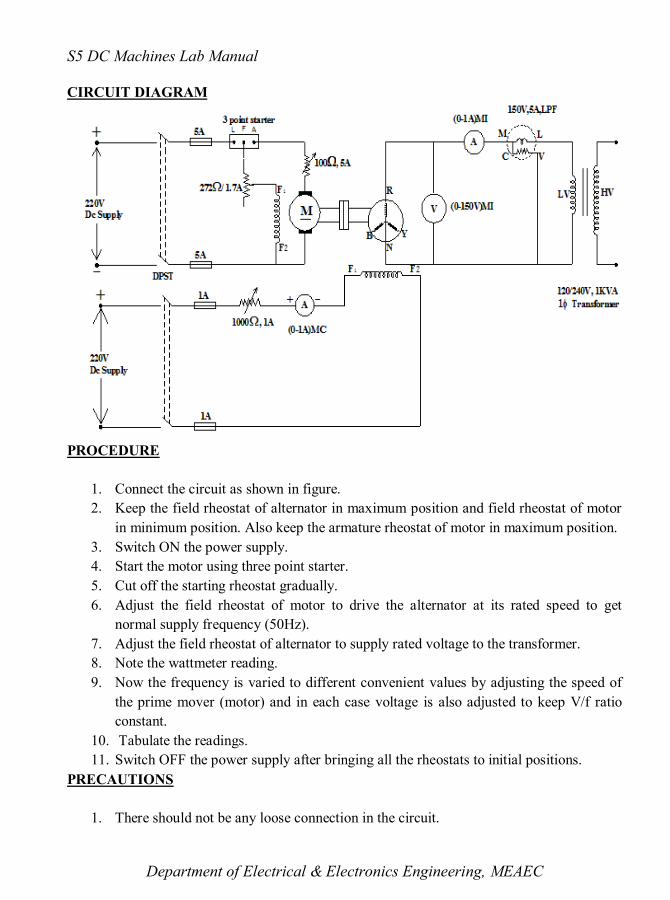
CIRCUIT DIAGRAM
PROCEDURE
1. Connect the circuit as shown in figure.
2. Keep the field rheostat of alternator in maximum position and field rheostat of motor
in minimum position. Also keep the armature rheostat of motor in maximum position.
3. Switch ON the power supply.
4. Start the motor using three point starter.
5. Cut off the starting rheostat gradually.
6. Adjust the field rheostat of motor to drive the alternator at its rated speed to get
normal supply frequency (50Hz).
7. Adjust the field rheostat of alternator to supply rated voltage to the transformer.
8. Note the wattmeter reading.
9. Now the frequency is varied to different convenient values by adjusting the speed of
the prime mover (motor) and in each case voltage is also adjusted to keep V/f ratio
constant.
10. Tabulate the readings.
11. Switch OFF the power supply after bringing all the rheostats to initial positions.
PRECAUTIONS
1. There should not be any loose connection in the circuit.

S5 DC Machines Lab Manual
Department of Electrical & Electronics Engineering, MEAEC
2. While varying the field rheostat of alternator, care must be taken so that the induced
voltage does not exceed the rated voltage on LV side of the transformer.
3. In each set of reading, the V/f ratio must be constant.
TABULAR COLUMN
Sl.No Speed, N
(rpm)
Frequency,
f ( Hz)
Voltage
V (V)
Power Pc
(W) Pc/f
1
2
3
4
5
6
7
SAMPLE GRAPH
SAMPLE CALCULATION
Speed, N=……………..Rpm N=120f/P
Frequency, f=NP/120=……………….Hz
Power, Pc=………………W Pc/f=…………………..W/Hz
From graph,
K1 =…………………..W/Hz K2= tan θ=………………W/Hz
2
S5 DC Machines Lab Manual
Department of Electrical & Electronics Engineering, MEAEC
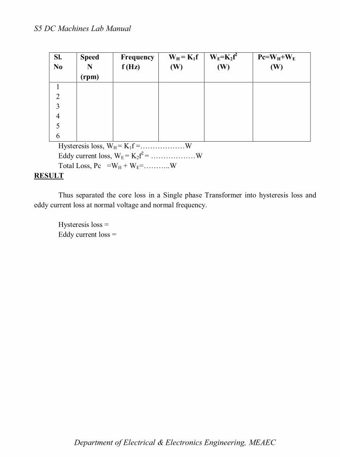
Sl.
No
Speed
N
(rpm)
Frequency
f (Hz)
WH = K1f
(W)
WE=K2f2
(W)
Pc=WH+WE
(W)
1
2
3
4
5
6
Hysteresis loss, WH = K1f =………………W
Eddy current loss, WE = K2f2 = ………………W
Total Loss, Pc =WH + WE=………..W
RESULT
Thus separated the core loss in a Single phase Transformer into hysteresis loss and
eddy current loss at normal voltage and normal frequency.
Hysteresis loss =
Eddy current loss =
S5 DC Machines Lab Manual
Department of Electrical & Electronics Engineering, MEAEC
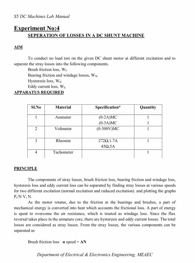
Experiment No:4 SEPERATION OF LOSSES IN A DC SHUNT MACHINE
AIM
To conduct no load test on the given DC shunt motor at different excitation and to
separate the stray losses into the following components.
Brush friction loss, WF
Bearing friction and windage losses, WW
Hysteresis loss, WH
Eddy current loss, WE
APPARATUS REQUIRED
PRINCIPLE
The components of stray losses, brush friction loss, bearing friction and windage loss,
hysteresis loss and eddy current loss can be separated by finding stray losses at various speeds
for two different excitation (normal excitation and reduced excitation). and plotting the graphs
Ps/N Vs N.
As the motor rotates, due to the friction at the bearings and brushes, a part of
mechanical energy is converted into heat which accounts the frictional loss. A part of energy
is spent to overcome the air resistance, which is treated as windage loss. Since the flux
reversal takes place in the armature core, there are hysteresis and eddy current losses. The total
losses are considered as stray losses. From the stray losses, the various components can be
separated as
Brush friction loss α speed = AN
Sl.No Material Specification* Quantity
1 Ammeter (0-2A)MC
(0-3A)MC
1
1
2 Voltmeter (0-300V)MC 1
3 Rheostat 272Ω,1.7A
45Ω,5A
1
4 Tachometer 1
S5 DC Machines Lab Manual
Department of Electrical & Electronics Engineering, MEAEC
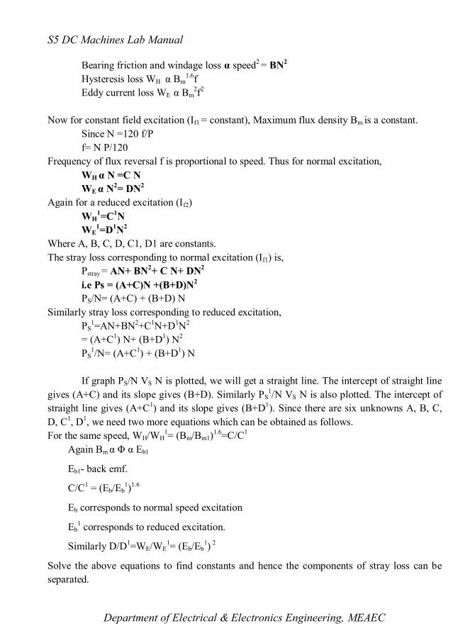
Bearing friction and windage loss α speed2 = BN
2
Hysteresis loss WH α Bm1.6
f
Eddy current loss WE α Bm2f
2
Now for constant field excitation (If1 = constant), Maximum flux density Bm is a constant.
Since N =120 f/P
f= N P/120
Frequency of flux reversal f is proportional to speed. Thus for normal excitation,
WH α N =C N
WE α N2= DN
2
Again for a reduced excitation (If2)
WH1=C
1N
WE1=D
1N
2
Where A, B, C, D, C1, D1 are constants.
The stray loss corresponding to normal excitation (If1) is,
Pstray = AN+ BN2+ C N+ DN
2
i.e Ps = (A+C)N +(B+D)N2
PS/N= (A+C) + (B+D) N
Similarly stray loss corresponding to reduced excitation,
PS1=AN+BN
2+C
1N+D
1N
2
= (A+C1) N+ (B+D
1) N
2
PS1/N= (A+C
1) + (B+D
1) N
If graph PS/N VS N is plotted, we will get a straight line. The intercept of straight line
gives (A+C) and its slope gives (B+D). Similarly PS1/N VS N is also plotted. The intercept of
straight line gives (A+C1) and its slope gives (B+D
1). Since there are six unknowns A, B, C,
D, C1, D
1, we need two more equations which can be obtained as follows.
For the same speed, WH/WH1= (Bm/Bm1)
1.6=C/C
1
Again Bm α Φ α Eb1
Eb1- back emf.
C/C1 = (Eb/Eb
1)
1.6
Eb corresponds to normal speed excitation
Eb1 corresponds to reduced excitation.
Similarly D/D1=WE/WE
1= (Eb/Eb
1)
2
Solve the above equations to find constants and hence the components of stray loss can be
separated.

S5 DC Machines Lab Manual
Department of Electrical & Electronics Engineering, MEAEC
CIRCUIT DIAGRAM
MEASUREMENT OF ARMATURE RESISTANCE
PROCEDURE
1. Connections are made as shown in the figure.
2. Keeping the field rheostat at its minimum position and the other at maximum position.
3. Switch ON the power supply.

S5 DC Machines Lab Manual
Department of Electrical & Electronics Engineering, MEAEC
4. Start the motor using three point starter.
5. Adjust the field rheostat to obtain rated excitation.
6. Now keeping the excitation constant, (as percentage rated value) the speed is reduced
to different values in steps by adjusting the armature rheostat.
7. All the meter readings and speed are noted.
8. Tabulate the readings.
9. Now keeping the excitation constant at a reduced (.75) the procedure explained above
is repeated and second set of readings are obtained.
10. These readings are tabulated.
PRECAUTIONS
1. There should not be any loose connection in the circuit.
2. The machine should be at no load.
3. Test should be conducted on DC shunt machine only.
4. Care is to taken to see that at least one reading in each set must have the same speed.
TABULAR COLUMN
Sl
No
N
(rpm)
V (V) Ia
(A)
If
(A)
Eb= V-IaRa
(V)
Ps= Eb*Ia
(W)
Ps/N
1
2
3
4
5
6
1
2
3
4
5
6

S5 DC Machines Lab Manual
Department of Electrical & Electronics Engineering, MEAEC
SAMPLE GRAPH
SAMPLE CALCULATION
From graph, A+C=…………….
A+C1=……………
C-C1=……………. (1)
B+D= tan θ1…………….
B+D1= tan θ2……………
D-D1=…………… (2)
Back emf at rated speed is,
For Rated Excitation
Eb=V-IaRa=…………..V
For reduced excitation
Eb1=V-Ia
1Ra=…………….V
C/C1 = (Eb/Eb
1)
1.6 =………….. (3)
D/D1=We/We
1= (Eb/Eb
1)
2 =……………. (4)
Solve equations (1), (2), (3) & (4), we get the values of A, B, C, and D
Therefore A=……….
B=…………

S5 DC Machines Lab Manual
Department of Electrical & Electronics Engineering, MEAEC
C=…………….
D=………………
C1=…………….
D1=……………
Brush friction loss, WF = AN =……………..W
Bearing friction and windage losses, WW= BN2=……………W
Hysteresis loss, WH= CN=………………….W
Eddy current loss, WE= DN2=………………W
Total Stray loss= AN+ BN2+ C N+ DN
2=………….W
RESULT
The stray losses at rated speed and rated excitation of a DC shunt machine has been
separated in to following components
Brush friction loss=………………W
Bearing friction and windage loss=…………….W
Hysteresis loss=………….W
Eddy current loss=……………W

S5 DC Machines Lab Manual
Department of Electrical & Electronics Engineering, MEAEC
Experiment No:5 SUMPNER’S TEST
AIM
To predetermine the efficiency and regulation of transformer at various loads and
power factor.
APPARATUS REQUIRED
PRINCIPLE
The Sumpner’s test is also called as back to back test or regenerative test. This
test facilitates the collection of data for OC and SC test simultaneously through a
single test. However two identical transformers are needed to perform this test.
The primary windings of the two transformers are connected in parallel to rated
voltage at rated frequency. The secondary windings are connected in phase opposition.
A small voltage is injected to secondary windings to circulate rated current or full load
current. Now the primary side wattmeter reads core loss of the two transformers and
secondary side wattmeter reads copper loss of two transformers.
Determination of efficiency
Transformer Efficiency =η = output/input
η=output/ (output +copper loss +iron loss)
Output power at full load = VICosΦ
=KVA x power factor
Output power at any load = X* VI CosΦ
= load factor* KVA x power factor
The efficiency at any load = X*KVAcosΦ*100
(X*KVAcosΦ +Wi + X2 Wcu)
Where Wi is the iron loss and Wcu is the copper loss.
Sl. No: Apparatus Specification* Quantity
1 1Φ Transformer 240/120 V, 2 KVA 2
2 Voltmeter 0-150 V, MI 1
3 Voltmeter 0-600 V, MI 1
4 Voltmeter 0-75 V, MI 1
5 Ammeter 0-2A, MI 1
6 Ammeter 0-10A, MI 1
7 Wattmeter 150 V, 5A, LPF
75V,10A,UPF
1
1
8 Auto transformer 0-270 / 8 A, 1Φ 2

S5 DC Machines Lab Manual
Department of Electrical & Electronics Engineering, MEAEC
Wi= W0/2 ; Wcu =X2 Wsc/2
Determination of Voltage Regulation
The voltage regulation of a transformer is the arithmetic difference (not phasor
difference) between the no-load secondary voltage (0V2) and the secondary voltage (V2) on
load expressed as percentage of no-load voltage. The change in voltage from no load to full
load can be replaced by the voltage drop from no load to full load.
In general voltage regulation at any load and any power factor can be determined by the
equation, % regulation = X*(ISCRo2cos Φ ± ISCXo2sinΦ)*100
V2
+sign indicates lagging power factor
-sign indicates leading power factor
CONNECTION DIAGRAM
PROCEDURE
1. Connections are made as per circuit diagram.
2. Keep the autotransformers in minimum position, Switch S in open position.
3. Vary the autotransformer in the primary side and set rated voltage in primary side.
4. Observe V3.

S5 DC Machines Lab Manual
Department of Electrical & Electronics Engineering, MEAEC
5. If the readings show zero voltage, it means that the secondary winding connection is
correct.
6. If the voltage V3 shows double of the rated voltage, interchange the secondary
winding connection.
7. Note down the readings of Voltmeter, Ammeter and Wattmeter.
8. Close the switch S.
9. Increase the voltage in the secondary by varying the autotransformer in the secondary
till rated current flow through the secondary winding.
10. Note down the readings of Voltmeter, Ammeter and Wattmeter.
PRECAUTIONS
1. There should not be any loose connection in the circuit.
2. For measuring power factor at no load, a low power factor wattmeter should be used.
3. The voltmeter connected across the switch has rating twice the secondary rating of the
transformer.
4. During SC test the supply voltage should be applied through an autotransformer from
zero value to higher value slowly and gradually till the ammeter indicates the full load
current. The measured current should not exceed the rated value.
TABULAR COLUMN
SAMPLE CALCULATION
For Efficiency
Power factor, cos Ø =…………….
Load factor, X= ……………….
Output power, Po= KVA*Power factor* Load factor
=X*KVA*Cos Ø
=……………….W
Iron loss, Wi= W0/2 =…………………W
Copper loss, Wcu= X2 Wsc/2=……………….W
Input power, Pi =Po + Wi + Wcu =…………………W
Efficiency=P0 / Pi*100
For Voltage Regulation
Power factor, cos Ø =…………….
Test Current (A) Voltage (V) Power (W)
OC 2Io = Vo = 2Wo =
SC Isc = 2Vsc = 2Wsc =

S5 DC Machines Lab Manual
Department of Electrical & Electronics Engineering, MEAEC
Load factor, X= ……………….
Voltage regulation for lagging power factor=X* (ISC Ro2cos Φ+ ISCXo2sinΦ)/V2*100
Voltage regulation for leading power factor=X* (ISC Ro2cos Φ – IScXo2sinΦ)/V2*100
For finding efficiency of the transformer
Sl
N
o
Power
factor
Load
factor
Output
Power
(W)
Iron
Loss
(W)
Cu
Loss
(W)
Input
Power
(W)
Efficiency
(%)
1
2
3
4
1
¼
½
¾
1
1
2
3
4
0.8
¼
½
¾
1
1
2
3
4
0.6
¼
½
¾
1
1
2
3
4
0.4
¼
½
¾
1
1
2
3
4
0.2
¼
½
¾
1
S5 DC Machines Lab Manual
Department of Electrical & Electronics Engineering, MEAEC
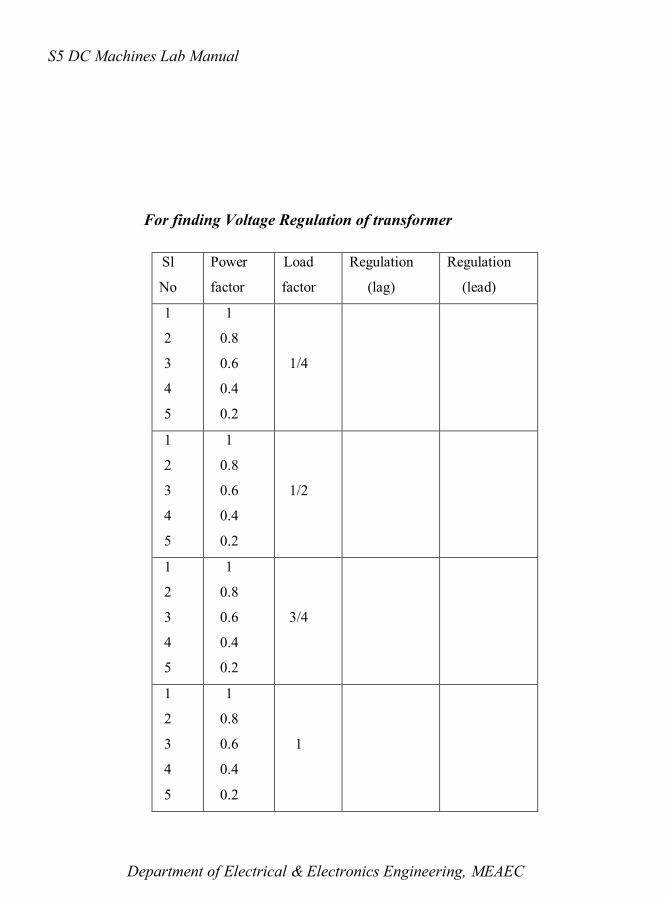
For finding Voltage Regulation of transformer
Sl
No
Power
factor
Load
factor
Regulation
(lag)
Regulation
(lead)
1
2
3
4
5
1
0.8
0.6
0.4
0.2
1/4
1
2
3
4
5
1
0.8
0.6
0.4
0.2
1/2
1
2
3
4
5
1
0.8
0.6
0.4
0.2
3/4
1
2
3
4
5
1
0.8
0.6
0.4
0.2
1

S5 DC Machines Lab Manual
Department of Electrical & Electronics Engineering, MEAEC
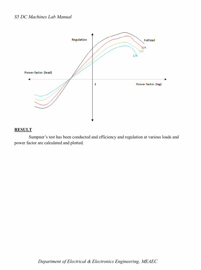
SAMPLE GRAPH
S5 DC Machines Lab Manual
Department of Electrical & Electronics Engineering, MEAEC
RESULT
Sumpner’s test has been conducted and efficiency and regulation at various loads and
power factor are calculated and plotted.