list of products - 4.imimg.com · 2 in 1 digital coating thickness gauge model - km 118a ......
TRANSCRIPT
®®
AN ISO 9001:2008 COMPANY
MODEL - KM 118A
2 IN 1 DIGITAL COATING
THICKNESS GAUGE
OPERATION MANUAL
G 17, Bharat Industrial Estate, T. J. Road, Sewree (W), Mumbai - 400 015. INDIA.
Sales Direct : (022) 24156638Tel. : (022) 24124540, 24181649. Fax : (022) 24149659
Email : [email protected] Website : www.kusamelectrical.com
www.kusam-meco.co.in
®
LIST OF PRODUCTS
¬ Digital Multimeter ¬ Digital AC & AC/DC Clampmeter
¬ AC Clamp Adaptor ¬ AC/DC Current Adaptor
¬ Thermo Anemometer ¬ Thermo Hygrometer
¬ Distance Meter ¬ Digital Lux Meter
¬ Network Cable Tester ¬ Power Factor Regulator
¬ Earth Resistance Tester ¬ Digital Panel Meters
¬ DC Power Supplies ¬ High Voltage Detector
¬ Calibrators ¬ Gas Analysers
¬ Frequency Counter ¬ Function Generator
¬ Phasing Sticks ¬ Battery Tester
¬ Waterproof Pen Testers ¬ Solar Power Meter
¬ EMF Detector
¬ Wood, Paper & Grain Moisture Meter
¬ Transistorised Electronic Analog & Digital Insulation
Resistance Testers(upto 10 KV)
¬ Digital Sound Level Meter & Sound Level Calibrator
¬ Digital contact & Non-contact Type Tachometer
¬ Digital Non-contact (infrared) Thermometer
¬ Maximum Demand Controller/Digital Power Meter
¬ Digital Hand Held Temperature Indicators

® ®
22
2 IN 1 DIGITAL COATING
THICKNESS GAUGE
MODEL - KM 118A
THIS WARRANTY IS BUYER’S SOLE AND EXCLUSIVE
REMEDY AND IS IN LIEU OF ALL OTHER WARRANTIES,
EXPRESS OR IMPLIED, INCLUDING BUT NOT LIMITED
TO ANY IMPLIED WARRANTY OF MERCHANTABILITY
OR FITNESS FOR A PARTICULAR PURPOSE. “KUSAM-
MECO” SHALL NOT BE LIABLE FOR ANY SPECIAL,
INDIRECT, INCIDENTAL OR CONSEQUENTIAL
DAMAGES OR LOSSES, INCLUDING LOSS OF DATA,
ARISING FROM ANY CAUSE WHATSOEVER.
All transaction are subject to Mumbai Jurisdiction.
G 17, Bharat Industrial Estate, T. J. Road, Sewree (W), Mumbai - 400 015. INDIA.
Sales Direct : (022) 24156638Tel. : (022) 24124540, 24181649. Fax : (022) 24149659
Email : [email protected] Website : www.kusamelectrical.com
www.kusam-meco.co.in
®

®®
21
TABLE OF CONTENTS
TITLE PAGE NO.
I. .................................
II. Features.......................................................
VI.
Introduction................
III. Safety Information......................................
V. Product Use................................................
Maintenance
VIII. Test Certificate...........................................
IX. Warranty......................................................
IV. Specifications.............................................
Measurements............................................
VII. ...............................................
01
01
01
05
06
09
18
19
20
WARRANTY
Each “KUSAM-MECO” product is warranted to be free from
defects in material and workmanship under normal use &
service. The warranty period is one year (12 months) and
begins from the date of despatch of goods. In case any defect
occurs in functioning of the instrument, under proper use,
within the warranty period, the same will be rectified by us free
of charges, provided the to and fro freight charges are borne
by you.
This warranty extends only to the original buyer or end-user
customer of a “KUSAM-MECO” authorized dealer.
This warranty does not apply for damaged sensors, LCD,
damaged PCB's, disposable batteries, carrying case, cables,
or to any product which in “KUSAM-MECO’s” opinion, has
been misused, altered, neglected, contaminated or damaged
by accident or abnormal conditions of operation or handling.
“KUSAM-MECO” authorized dealer shall extend this
warranty on new and unused products to end-user customers
only but have no authority to extend a greater or different
warranty on behalf of “KUSAM-MECO”.
“KUSAM-MECO’s” warranty obligation is limited, at option,
free of charge repair, or replacement of a defective product
which is returned to a “KUSAM-MECO” authorized service
center within the warranty period.

® ®
2001
I. INTRODUCTION :
KM 118A is a ferrous coating thickness gauge designed for simply one hand operation.
II. FEATURES :
1. LED backlight.2. LCD display reverse.3. Auto power off.4. Low-battery indicator.5. Calibration for normal use.6. Data logging function.7. Warning beeper triggers by hi/lo limit settings.8. Inch and Metric measurement options.9. Zeroing Plate and Standard Coating Plate.10. Attached with carrying strap.11. Soft carrying case.
III. SAFETY INFORMATION :
It is recommended that you read the safety and operation instructionsbefore using the coating thickness gauge.
1. CAUTION :
1. Do not use the unit near any device whichgenerates strong electromagnetic radiationor near a static electrical charge, as thesemay cause errors.
2. Do not use the unit where it may be exposed to corrosive or explosive gases.The unit may be damaged, or explosion may occur.
MUMBAI
TEST CERTIFICATE
2 IN 1 DIGITAL COATING THICKNESS GAUGE
This Test Certificate warrantees that the product has been
inspected and tested in accordance with the published
specifications.
The instrument has been calibrated by using equipment
which has already been calibrated to standards traceable
to national standards.
MODEL NO. ________________KM 118A
SERIAL NO. ___________
DATE: ___________
ISO 9001REGISTERED
QC
PASS
KUSAM-MECO

® ®
0219
3. Do not keep or use this unit in an environment where it will bedirectly illuminated by sunshine, or where it condensation. If you do, it may be deformed, its insulation may be damaged, orit may no longer function according to specification.
4. Do not place the meter on or around hot objects (70°C/158°F).It may cause damage to the case.
5. If the meter is exposed to significant changes in ambient temperature, allow 30 minutes for temperature stabilization,before taking measurement.
6. Condensation may form on the sensor when going from a coldto hot environment. Wait for 10 minutes for condensation todissipate before taking measurements.
7. This unit is not constructed to be waterproofand dustproof. Do not use it in a wet or very dusty environment.
8. In order to take accurate measurement, makesure the sensing tip contacts the coatedsurface tightly without tilting.
9. Please make sure there is no air bubbles between substrate and coating.
10.Substrate zeroing calibration must be implemented for each use.
11. Two point calibration is suggested to implement for frequent testing points to increase measuring accuracy.
12.The enclosed zeroing plates are only suitable for the use of calibration of coating thickness meter itself. Apart from that, themeter should be performed two point calibration methods to getaccurate readings before use. The zeroing on specific materialsubstrate still needs to be done before taking formal measurements, such as Iron, Steel, Bronze, Copper, Nickel, Zinc and SUS304 and so on, which is to avoid the measuringerrors that cause by the difference of individual substrates. Theend users can get much more accurate measuring readings onthe specific metal under test by doing two calibration methods.
VII. MAINTENANCE :
Installing and Replacing Battery :
1. Power is supplied by 2pcs 1.5V (AAA size).
2. The “ ” appears in the display when battery replacement isneeded.
+
3. Remove the battery cover by gently sliding it onwards the bottomof the meter.
4. Remove the batteries from battery compartment.5. Replace with 2 new AAA batteries with polarity as indicated on
the bottom of Battery Compartment.6. Replace the Battery Cover.
Caution :When not in use for long periods remove battery. Do not storein locations with high temperatures, or high humidity.
Cleaning :Periodically wipe the case with a damp cloth and detergent, do notuse abrasives or solvents.

03
® ®
18
2. WARNING :
A. Electromagnetic Field Interference :
This instrument uses magnetic field method to measure the
coating thickness on ferrous metal base. If this meter was placed
in the environment with 20mG (mini Gauss) or above, the accuracy
would be affected. Suggest that the meter should to put far away
from the interfered source at least 30cm.
B. Electromagnetic Field Strength : (µ unit = mini Gauss)
Electromagnetic Source
Cellular Phone Charger
Notebook Power Supply
LCD Display
Fan
Reading Lamp
µ Any product with coil inside should be considered.
0cm
50 ~ 500
100 ~ 1000
10 ~ 100
100 ~ 1000
400 ~ 4000
30cm
< 1
< 5
< 1
< 5
< 10
Calibrating Point Clearance :
0000Fe mm
In measuring mode, press button over
2 seconds to clear Calibrating Point. LCD will
display “0000”. When calibration is not operated
properly, the clearance function helps users to
start it again.
BASE>2S
ZERO
3. Operation :
(1) Keep the meter away any substrate or any magnetic field.
(2) Put the sensing tip to contact coated surface tightly until for
the bleep to sound and reading appears.
(3) If the coating thickness is out off range, the meter shows
“----”.

17
® ®
04
Recommended operating conditions (> 30cm)
Fe mm
i00
102 ± 2 micron
ADAPTOR
Fe mm
i00mG
08.mG
08.
Abnormal operating conditions (< 30cm)
102 ± 2 micron
ADAPTOR
mG
768.mG
768.
Fe mm
i25 Fe mm
i25
Press or button to select the mm or mils.mmu
After it’s selected, press button to exit the
unit selecting and return to measuring mode.
MENU
u mils
fe Substrate Material Setting :
Fe mmfe
In this mode, press button to enter to Substrate
Material setting.
MENU
ffe
After it’s selected, press button to exit the
unit selecting and return to measuring mode.
MENU
Press or button to select the AUTO or
NON-ferrous or Ferrous substrate material.fe
a
fefe
05
® ®
16
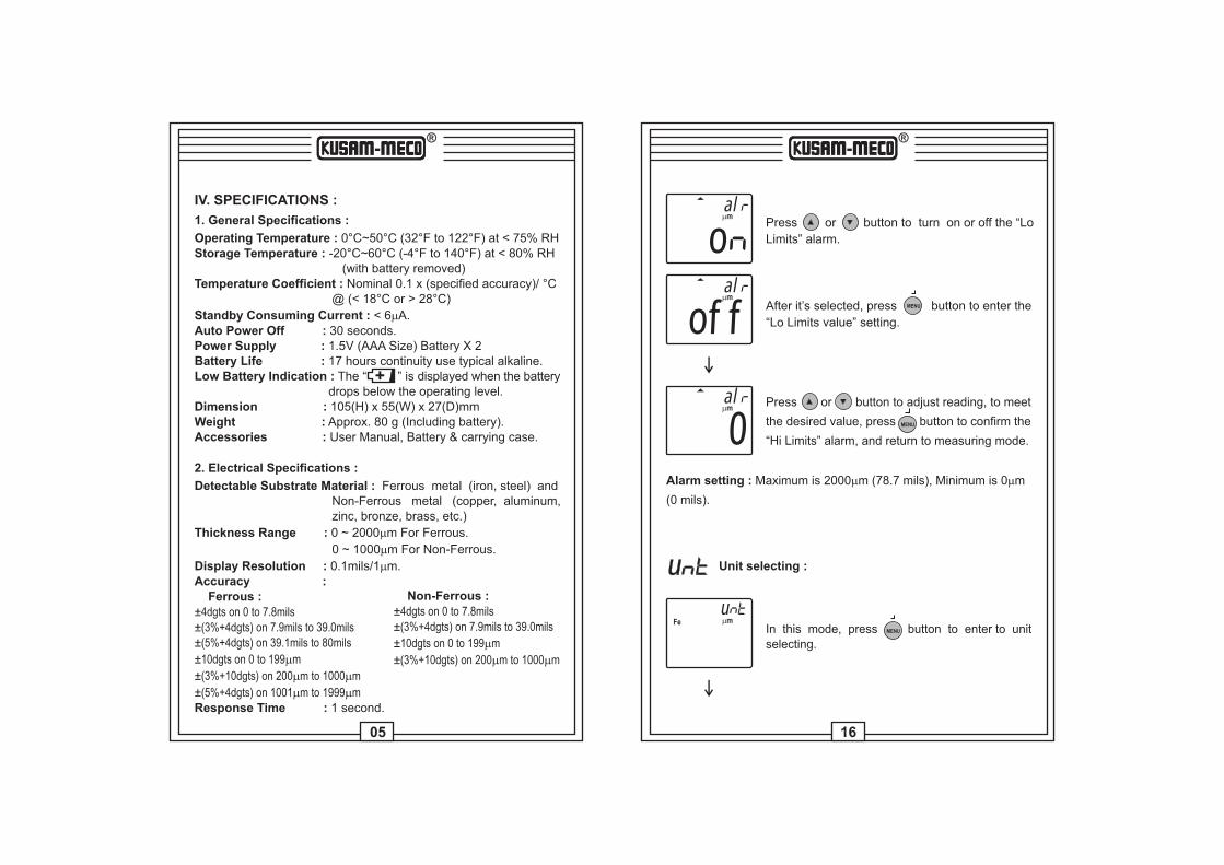
IV. SPECIFICATIONS :
1. General Specifications :
Operating : 0°C~50 C (32 F to 122 F) at < 75% RHTemperature ° ° °Storage Temperature : -20°C~60°C (-4°F to 140°F) at < 80% RH (with battery removed)Temperature Coefficient : Nominal 0.1 x (specified accuracy)/ °C @ (< 18°C or > 28°C)
Standby Consuming Current : < 6mA.Auto Power Off : 30 seconds.Power Supply : 1.5V (AAA Size) Battery X 2Battery Life : 17 hours continuity use typical alkaline.Low Battery Indication : The “ ” is displayed when the battery drops below the operating level.Dimension : 105(H) x 55(W) x 27(D)mmWeight : Approx. 80 g (Including battery).Accessories : User Manual, Battery & carrying case.
+
2. Electrical Specifications :
Detectable Substrate Material : Ferrous metal (iron, steel) and Non-Ferrous metal (copper, aluminum, zinc, bronze, brass, etc.)
Thickness Range : 0 ~ 2000mm For Ferrous.
0 ~ 1000mm For Non-Ferrous.
Display Resolution : 0.1mils/1mm.Accuracy : Ferrous :±4dgts on 0 to 7.8mils±(3%+4dgts) on 7.9mils to 39.0mils±(5%+4dgts) on 39.1mils to 80mils
±10dgts on 0 to 199mm
±(3%+10dgts) on 200mm to 1000mm
±(5%+4dgts) on 1001mm to 1999mmResponse Time : 1 second.
Non-Ferrous :±4dgts on 0 to 7.8mils±(3%+4dgts) on 7.9mils to 39.0mils
±10dgts on 0 to 199mm
±(3%+10dgts) on 200mm to 1000mm
ommal
Press or button to turn on or off the “Lo
Limits” alarm.
After it’s selected, press button to enter the
“Lo Limits value” setting.
MENU
offmmal
0mmal Press or button to adjust reading, to meet
the desired value, press button to confirm the
“Hi Limits” alarm, and return to measuring mode.
MENU
Alarm setting : Maximum is 2000mm (78.7 mils), Minimum is 0 m
(0 mils).
m
u Unit selecting :
In this mode, press button to enter to unitselecting.
MENU
Fe mmu
®
15
®
06
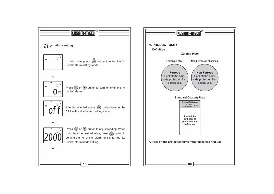
V. PRODUCT USE :
1. Definition :
Zeroing Plate
µ Peel off the protection films from foil before first use.
Standard Coating Plate
Standard Thickness :
39.6 mils1006 micron
± 1%
Peel off theboth side of
protection filmbefore use
Ferrous is steel
FerrousPeel off the other
side protection filmbefore use.
Non-FerrousPeel off the other
side protection filmbefore use.
Non-Ferrous is aluminum
al Alarm setting :
Fe mmal
In this mode, press button to enter the “Hi
Limits” alarm setting mode.
MENU
oFe mm
alPress or button to turn on or off the “Hi
Limits” alarm.
After it’s selected, press button to enter the
“Hi Limits value” alarm setting mode.
MENU
offFe mm
al
2000mmal Press or button to adjust reading. When
it displays the desired value, press button to
confirm the “Hi Limits” alarm, and enter the “Lo
Limits” alarm mode setting.
MENU

07
® ®
14
2. The Product :
NFe mmMAX - MIN mils888+
8888..AVG CALn
MEMSET
LCD
FunctionKey
SensingTip
NFemmmils
BASE>2S
MENU
> 2S DEL
ESC
ZERO
A. Recalling previous records :
MAX
MIN
MAX-MIN
AVG
n
n
n
(Maximum reading)
(Minimum reading)
(Maximum - Minimum reading)
(Average reading)
Number of the recorded data
The first data
The 255th data
:
B. To delete all recorded data :
Fe mmel
p
Press button for five seconds.MENU
Press or button to select the delete or
.yes
, press button to return to browse previous
records.
MENU
yes , press button to delete record and return
to the measuring mode.
MENU
To exit this mode, press button. Press or
button to browse previous records, its
sequence as follows :
MENUFe mm
MEM ec
oMAX

13
® ®
08
DEL
ESCJumped off & return of the previous mode.
Up/down adjusting, (select function-value)
Press the button to substrate Zeroing calibration.Press the button for 2 seconds to clear CalibratingPoint.BASE>2S
ZERO
µ During measure mode :DEL
ESC The three buttons are disabled.
µ During setting mode :
The two buttons are disabled.> 2S
BASE>2S
ZERO
BASE>2S
MENU
> 2S DEL
ESC
ZERO
3. Buttons :
Buttons Function
MENU
> 2S
Press the button to enter MENU/ selecting.
Press the button to reverse the display.Press the button for 2 seconds to turn onor off backlight.
Press the tip of the Gauge to contact coated
surface tightly (Standard coating plate 1006mm orstandard coating plate), wait for one “Beep” soundannounces, exit two point calibration and return tomeasuring mode.
Fe mm
pushCAL h
Before users finish two point calibration, if press button to exit
two point calibration, since the calibration is not finished, it will not
record its previous calibrated value.
DEL
ESC
ec Record setting/recall :
The product can record 255 samples.Stop recording after the 255th measured value.
In this mode, press button to enter recordingsetting.
MENU
Fe mmec
Press or button to select the record on or
off.
Fe mm
MEM ec
o
After it’s selected, press button to confirm.MENU
Fe mmec
off

®
1209
®
No. Symbol Meaning
1
2
3
4
5
6
7
Fe, NFe
MAX
MIN
MAX - MIN
AVG
n
,
CAL
mm, mils
Ferrous/Non-Ferrous
Maximum reading
Minimum reading
Maximum - Minimum reading
Average reading
Number of the reading
Low battery
Alarm indicator
Record is activated
Calibration is activated
Measurement units
+
MEM
4. The Display :
7
6543
2
1NFe mmMAX - MIN mils
888+
8888..AVG CALn
MEMSET
NFemmmils
CAL Two Point Calibration :
µDuring two point calibration, the foil and standard coating
plate 1006mm can be replaced by uncoated substrate and astandard coating plate with known-thickness.
µWhen it is calibrated by user, its max calibrated value is
1100mm (43.3 mils),
Fe mmCAL
In this mode, press button to enter two pointcalibration.
MENU
Fe mm
0CAL L Into “low” value adjustments of the two point
calibration, press or button to adjust
reading, when it displays the desired value,
press button to confirm.MENU
Fe mm
pushCAL L
Press the tip of the Gauge to contact coatedsurface tightly (Zeroing plate or uncoated substrate). Wait for one “Beep” sound announces.
Fe mm
1006CAL h Into “Hi” value adjustments of the two point
calibration, press or button to adjust
reading, when it display the desired value,
press button to confirm.MENU

®
1110
®
1. Auto Power Off (APO) :
Leave the gauge without operation for 30 seconds, power turns offautomatically.
µ During set mode, Auto Power Off function will be inactivated.
Measuring :
1. Gauge automatically powers up and Measuring when probe ispressed.
2. Put the probe to contact coated surface tightly, wait for the reading to appear and measurement is completed. (One sound“Beep” announced)
3. If the coating thickness is out of range, the meter shows “----”.
CAUTION :
Keep the sensing tip of the meter away from any substrate orany magnetic field.
4. When the alarm is activated, measured exceed “Hi Limits” or “Lo Limits”, LCD display (updated) the measured value will be litup along with pressing or symbol, the beeper emits a continuous or pulsed tone, warm users exceeds the Hi or LoLimits value.
VI. MEASUREMENTS : 2. Menu :
In measuring mode, press button to enter menus, will blink.CALMENU
With and button to select the function, browse the menus :
u
ec
al
CAL Two Point Calibration
Record Setting/Recall
Alarm Setting
Measurement Units
Substrate Material Settingfe