litesport - moyes russiamoyes-russia.com/wp-content/uploads/2012/03/litesportmanual.pdf · glider...
TRANSCRIPT

Moyes Delta Gliders Pty. Ltd. Version 1.03
LITESPORT owners manual


LITESPORT OWNERS MANUAL
Version 1.03 1
CONTENTS Amendments......................................................................................... 2
Introduction ........................................................................................... 3
Description of Design ............................................................................ 4
Specifications........................................................................................ 5
Operating Limitations ............................................................................ 7
Disclaimer ............................................................................................. 8
Assembly Procedures ........................................................................... 8
Pre-Flight Check ................................................................................. 17
De-Rigging the Litesport ..................................................................... 19
Flying The Moyes Litesport ................................................................. 23
Tuning Hints........................................................................................ 27
Glider Care ......................................................................................... 31
Maintenance Schedule ....................................................................... 33
Sail Removal....................................................................................... 34
Checking The Litesport Stability System ............................................ 35
AN Bolt Index ................................................................................. 36
Purchase Record ................................................................................ 37
Maintenance Log ................................................................................ 37

LITESPORT OWNERS MANUAL
2 Version 1.03
AMENDMENTS
Version Date Changes
1.00 20/08/2003 Created original owners manual.
1.01 5/05/2004 • Added Zoom Upright Assembly Drawing • Updated Stability System instructions
1.02 3/04/2006 • Corrected Nose Angle Specification for Litesport 3.
1.03 19/05/2008 • Corrected computational error on page 35 – Checking the Litesport Stability System – Step three.

LITESPORT OWNERS MANUAL
Version 1.03 3
Moyes Delta Gliders Pty. Ltd. 1144 Botany Road, Botany NSW 2019 Australia T: +61 (0)2 9316-4644 F: +61 (0)2 9316-8488 E: [email protected]
INTRODUCTION Thank you for choosing the Moyes Litesport. You have chosen wisely. The Litesport incorporates the latest hang gliding design innovations to bring Moyes into the future. The Litesport bridges the gap between intermediate and topless gliders, providing a very capable glider for either the advancing pilot, or the an advanced recreational pilot. Since 1967, Moyes Delta Gliders has strived to be on the cutting edge of developing hang gliders of the highest calibre. A family owned business operating under homespun values, we aim to provide a comprehensive international network to service all pilots. Even further, we work with some of the best pilots in the world to ensure that our gliders are stringently made and tested in order to improve their performance, handling, and safety. We wish you the very best flying, The Moyes Team
LITESPORT OWNERS MANUAL
4 Version 1.03
DESCRIPTION OF DESIGN
Designed by elite competition pilots, the Moyes Litesport is intended for competition and enjoyable high performance cross country flying. The Litesport utilises a planform similar to the Litespeed. The Litesport features a 7075T6 aluminium airframe, which allows a considerable weight saving over more conventional alloys. The leading edge uses a step down taper design with revised sleeving and tube diameters. This produces a lighter outer leading edge with an improved flex distribution. The low roll inertia provides pleasant handling. The elliptical fibreglass wing tip has been a feature of Moyes high performance gliders since the early 80’s. The fibreglass tip creates better turn coordination compared to conventional designs. With the VG fully engaged, the fibreglass tip produces a tighter mainsail and more desirable washout distribution. The pitch stability system utilises a cable braced outer aluminium sprog, providing support for battens 8 and 9 via a transversal batten. This system was designed with maximum strength and stiffness in mind, and demonstrates excellent structural integrity under any flight load. In addition, the kingpost incorporates the G-string compensation system, which lowers the rear of the sail when the VG is engaged. This allows the luff line to adjust to the decrease in washout produced by the VG system. The Litesport sail has a total of 8 internal cloth ribs. These ribs prevent the under surface from ‘blowing down’, which makes pilot induced oscillations less likely. These internal ribs are shaped to produce the desired under surface camber for low drag at high speeds.
LITESPORT OWNERS MANUAL
Version 1.03 5
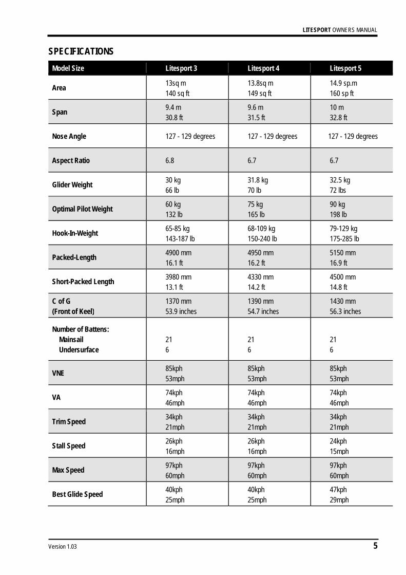
SPECIFICATIONS Model Size Litesport 3 Litesport 4 Litesport 5
Area 13sq m 140 sq ft
13.8sq m 149 sq ft
14.9 sp.m 160 sp ft
Span 9.4 m 30.8 ft
9.6 m 31.5 ft
10 m 32.8 ft
Nose Angle 127 - 129 degrees 127 - 129 degrees 127 - 129 degrees
Aspect Ratio 6.8 6.7 6.7
Glider Weight 30 kg 66 lb
31.8 kg 70 lb
32.5 kg 72 lbs
Optimal Pilot Weight 60 kg 132 lb
75 kg 165 lb
90 kg 198 lb
Hook-In-Weight 65-85 kg 143-187 lb
68-109 kg 150-240 lb
79-129 kg 175-285 lb
Packed-Length 4900 mm 16.1 ft
4950 mm 16.2 ft
5150 mm 16.9 ft
Short-Packed Length 3980 mm 13.1 ft
4330 mm 14.2 ft
4500 mm 14.8 ft
C of G (Front of Keel)
1370 mm 53.9 inches
1390 mm 54.7 inches
1430 mm 56.3 inches
Number of Battens: Mainsail Undersurface
21 6
21 6
21 6
VNE 85kph 53mph
85kph 53mph
85kph 53mph
VA 74kph 46mph
74kph 46mph
74kph 46mph
Trim Speed 34kph 21mph
34kph 21mph
34kph 21mph
Stall Speed 26kph 16mph
26kph 16mph
24kph 15mph
Max Speed 97kph 60mph
97kph 60mph
97kph 60mph
Best Glide Speed 40kph 25mph
40kph 25mph
47kph 29mph

LITESPORT OWNERS MANUAL
6 Version 1.03
Best Glide Angle 14:1 14:1 14:1
Glide Angle 10:1 58kph 36mph
58kph 36mph
58kph 36mph
LITESPORT OWNERS MANUAL
Version 1.03 7
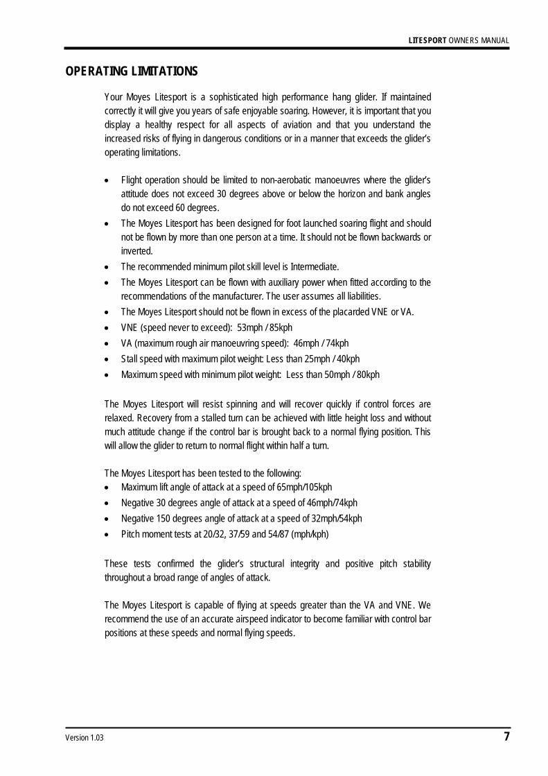
OPERATING LIMITATIONS
Your Moyes Litesport is a sophisticated high performance hang glider. If maintained correctly it will give you years of safe enjoyable soaring. However, it is important that you display a healthy respect for all aspects of aviation and that you understand the increased risks of flying in dangerous conditions or in a manner that exceeds the glider’s operating limitations. • Flight operation should be limited to non-aerobatic manoeuvres where the glider’s
attitude does not exceed 30 degrees above or below the horizon and bank angles do not exceed 60 degrees.
• The Moyes Litesport has been designed for foot launched soaring flight and should not be flown by more than one person at a time. It should not be flown backwards or inverted.
• The recommended minimum pilot skill level is Intermediate. • The Moyes Litesport can be flown with auxiliary power when fitted according to the
recommendations of the manufacturer. The user assumes all liabilities. • The Moyes Litesport should not be flown in excess of the placarded VNE or VA. • VNE (speed never to exceed): 53mph / 85kph • VA (maximum rough air manoeuvring speed): 46mph / 74kph • Stall speed with maximum pilot weight: Less than 25mph / 40kph • Maximum speed with minimum pilot weight: Less than 50mph / 80kph The Moyes Litesport will resist spinning and will recover quickly if control forces are relaxed. Recovery from a stalled turn can be achieved with little height loss and without much attitude change if the control bar is brought back to a normal flying position. This will allow the glider to return to normal flight within half a turn. The Moyes Litesport has been tested to the following: • Maximum lift angle of attack at a speed of 65mph/105kph • Negative 30 degrees angle of attack at a speed of 46mph/74kph • Negative 150 degrees angle of attack at a speed of 32mph/54kph • Pitch moment tests at 20/32, 37/59 and 54/87 (mph/kph) These tests confirmed the glider’s structural integrity and positive pitch stability throughout a broad range of angles of attack. The Moyes Litesport is capable of flying at speeds greater than the VA and VNE. We recommend the use of an accurate airspeed indicator to become familiar with control bar positions at these speeds and normal flying speeds.

LITESPORT OWNERS MANUAL
8 Version 1.03
DISCLAIMER The owner and operator must understand that due to the inherent risk involved in flying such a unique vehicle, no warranty is made or implied, of any kind, against accidents, bodily injury, or death. Operations such as aerobatic manoeuvres or erratic pilot technique may produce equipment failure. This glider is not covered by product liability insurance, neither has it been designed, manufactured, or tested, to any state or federal government airworthiness standard or regulation.

LITESPORT OWNERS MANUAL
Version 1.03 9
GETTING STARTED Your new Moyes Litesport may have been shipped to you in the 4.5m breakdown form. If so, you can assemble your glider to its full length by following these assembly procedures. All references to ‘top’, ‘bottom’, ‘left’, and ‘right’ refer to the glider and pilot in flying mode. Please check your packing list. • Glider • 2 x back section leading edges: note that the back sections are labelled left and
right. • 1 x batten set: red = left/ green = right/ blue = undersurface • 1 x speed bar • 2 x tip bags • 4 x padding pieces: A-frame top & bottom, keel sleeve, king post top • 1 x Snack Pack with owners’ manual, batten pattern, and promotional wear.
Assembly from 4.5m Breakdown Form 1. Open the glider bag and roll the glider onto its undersurface. Undo the straps and
extend the sail.
Picture 1 Lay the glider on its undersurface and unfold the sail.
2. Expose the leading edge/cross bar junction through the inspection zipper. Remove
the bubble wrap and tape from the leading edge/cross bar junction and the end of the middle sleeve.
LITESPORT OWNERS MANUAL
10 Version 1.03
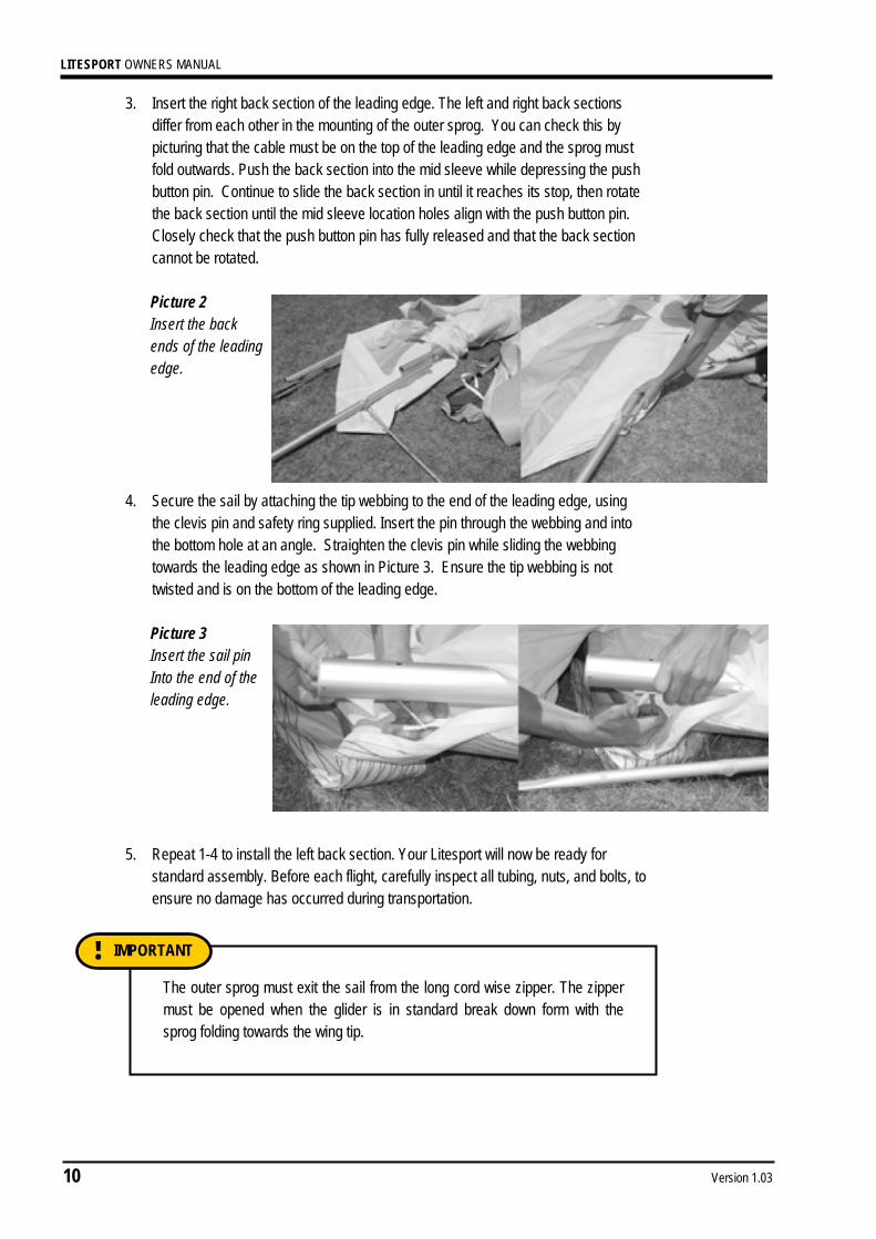
3. Insert the right back section of the leading edge. The left and right back sections differ from each other in the mounting of the outer sprog. You can check this by picturing that the cable must be on the top of the leading edge and the sprog must fold outwards. Push the back section into the mid sleeve while depressing the push button pin. Continue to slide the back section in until it reaches its stop, then rotate the back section until the mid sleeve location holes align with the push button pin. Closely check that the push button pin has fully released and that the back section cannot be rotated.
Picture 2 Insert the back ends of the leading edge.
4. Secure the sail by attaching the tip webbing to the end of the leading edge, using
the clevis pin and safety ring supplied. Insert the pin through the webbing and into the bottom hole at an angle. Straighten the clevis pin while sliding the webbing towards the leading edge as shown in Picture 3. Ensure the tip webbing is not twisted and is on the bottom of the leading edge.
Picture 3 Insert the sail pin Into the end of the leading edge.
5. Repeat 1-4 to install the left back section. Your Litesport will now be ready for
standard assembly. Before each flight, carefully inspect all tubing, nuts, and bolts, to ensure no damage has occurred during transportation.
The outer sprog must exit the sail from the long cord wise zipper. The zipper must be opened when the glider is in standard break down form with the sprog folding towards the wing tip.
IMPORTANT !

LITESPORT OWNERS MANUAL
Version 1.03 11
With standard uprights, the uprights will naturally toe-in as shown in Picture 4. Hold the base bar and the upright, twisting the upright so the connection lines up.
ASSEMBLY PROCEDURES 1. Place the glider on the ground, zipper facing up. Open the bag, undo the ties, and
remove the A-frame bottom padding and battens.
2. Assembly the A-Frame.
Picture 4 Standard uprights and basebar assembly.
3. Roll the glider over so that it is standing on the control frame.
Picture 5 Standard uprights and basebar assembly.
4. Remove the glider bag and any remaining ties and padding.
NOTE !
LITESPORT OWNERS MANUAL
12 Version 1.03
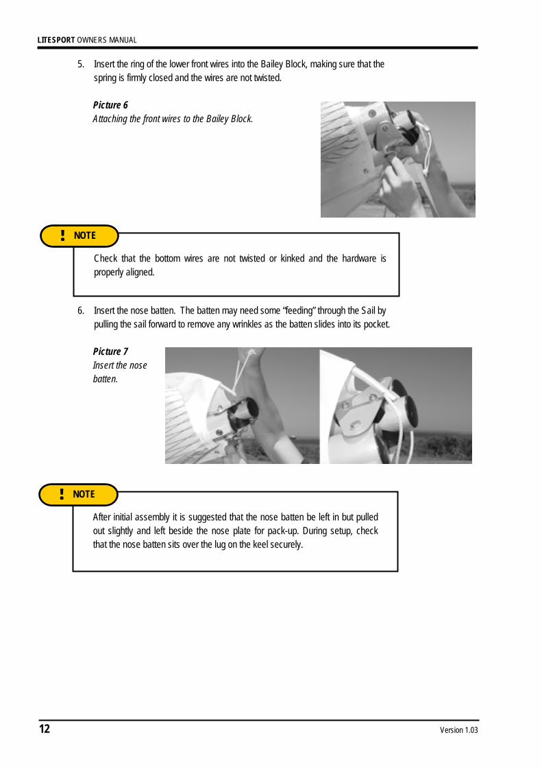
After initial assembly it is suggested that the nose batten be left in but pulled out slightly and left beside the nose plate for pack-up. During setup, check that the nose batten sits over the lug on the keel securely.
NOTE !
5. Insert the ring of the lower front wires into the Bailey Block, making sure that the spring is firmly closed and the wires are not twisted.
Picture 6 Attaching the front wires to the Bailey Block.
6. Insert the nose batten. The batten may need some “feeding” through the Sail by pulling the sail forward to remove any wrinkles as the batten slides into its pocket.
Picture 7 Insert the nose batten.
Check that the bottom wires are not twisted or kinked and the hardware is properly aligned.
NOTE !

LITESPORT OWNERS MANUAL
Version 1.03 13
7. Carefully spread each wing, making sure that you do not raise them above the level of the keel. Ensure that the king post rises straight up. This prevents the twisting of the keel mount channel bracket.
Picture 8 Spread the wings carefully.
8. To tension the crossbar, pull the cord coming out of the keel pocket. Check that the cable and rope are not twisted and that the shackle is secured within the Bailey Block. Attach the king post rear wire behind the shackle, in the Bailey Block. In strong winds the glider can be difficult to tension. Have a helper gently raise and pull forward one wing.
Picture 9 Tension the Glider.
Check bottom wires are not twisted or kinked.
NOTE !
DO NOT USE EXCESSIVE FORCE WHEN TENSIONING THE GLIDER. If excess force is encountered check:
The side wires are not twisted or kinked The cross bar retainer wire is not caught on the nose plate assembly The pull back wire or VG pulleys are not caught in the hang loop assembly
WARNING

LITESPORT OWNERS MANUAL
14 Version 1.03
9. The Litesport is equipped with a removable keel aft section. The glider can be left resting on it, facilitating the fitment of the washout strut and battens. If desired, the glider may now be raised onto its keel to complete the assembly. This also assists with keeping the sail clean by keeping the tips off the ground.
Picture 10 Raising the glider onto the keel can make assembly easier and keeps the sail clean.
10. Gently insert battens 1-6, moving from the centre of the wing towards the mid span. Use light force when inserting the battens, as this will greatly extend the longevity of the batten pockets. Red tipped battens are for the left wing, green for the right, and blue for the under surface.
11. Open the zipper at the tip of the sail. Slide the fibreglass rod through the end of the
sail and into the end of the leading edge. Ensure that the rod is pushed hard against its stop. Picture 11 Insert the glass wing tip
The glider may fall to one side if pushed or blown by the wind - this may result in wing tip damage. It is recommended that you only use in flat level ground and in nil wind. Use with care!
WARNING !
LITESPORT OWNERS MANUAL
Version 1.03 15
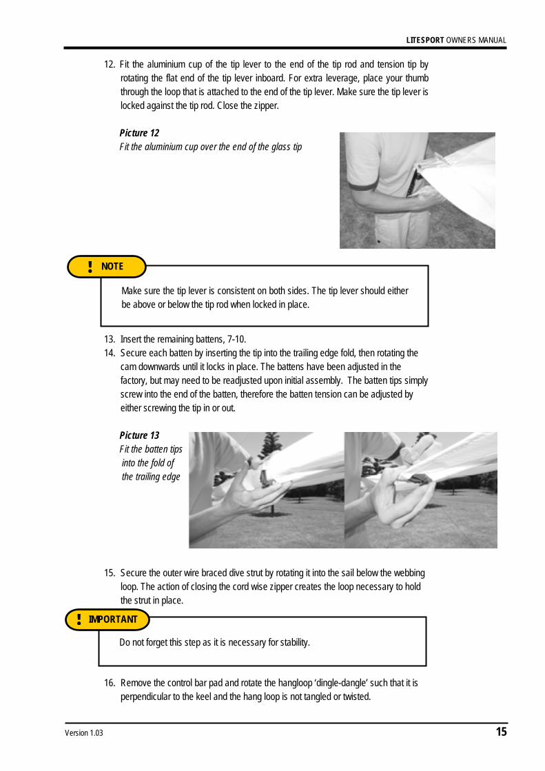
12. Fit the aluminium cup of the tip lever to the end of the tip rod and tension tip by rotating the flat end of the tip lever inboard. For extra leverage, place your thumb through the loop that is attached to the end of the tip lever. Make sure the tip lever is locked against the tip rod. Close the zipper.
Picture 12 Fit the aluminium cup over the end of the glass tip
13. Insert the remaining battens, 7-10. 14. Secure each batten by inserting the tip into the trailing edge fold, then rotating the
cam downwards until it locks in place. The battens have been adjusted in the factory, but may need to be readjusted upon initial assembly. The batten tips simply screw into the end of the batten, therefore the batten tension can be adjusted by either screwing the tip in or out. Picture 13 Fit the batten tips into the fold of the trailing edge
15. Secure the outer wire braced dive strut by rotating it into the sail below the webbing
loop. The action of closing the cord wise zipper creates the loop necessary to hold the strut in place.
16. Remove the control bar pad and rotate the hangloop ‘dingle-dangle’ such that it is perpendicular to the keel and the hang loop is not tangled or twisted.
Make sure the tip lever is consistent on both sides. The tip lever should either be above or below the tip rod when locked in place.
NOTE !
Do not forget this step as it is necessary for stability.
IMPORTANT !

LITESPORT OWNERS MANUAL
16 Version 1.03
17. Insert the under surface battens through the small holes in the under surface. Once fully inserted, pull each batten back slightly to secure it within the pocket.
18. Fit the nose fairing using the attached Velcro patches.
Picture 14 Insert the mylar tab on the nose fairing under the leading edge.
Picture 15 Pull the top rear of the nose fairing towards the rear of the sail. Securing it in place by the Velcro.
Picture 16 Attach the lower tabs of the nose fairing to the Velcro on the undersurface.

LITESPORT OWNERS MANUAL
Version 1.03 17
PRE-FLIGHT CHECK As with most high performance hang gliders, much of the hardware and structure is enclosed within the sail to improve the aerodynamics of the wing. This means that it is necessary to inspect the important structural components by looking inside the sail. It is important to develop a consistent pre-flight routine that incorporates all the necessary checks. If a distraction interrupts the routine, the pre-flight should be re-started to ensure that nothing has been missed.
1. As you should have already attached your harness to the glider, check that it is set up correctly. Ensure that your parachute is mounted correctly and that the bridle runs cleanly to the carabineer. If your harness height from the base bar needs adjustment, it is best to acquire the correct length hang loop from your Moyes agent.
2. Move up to the suspension system and verify that the ‘dingle-dangle’ is rotated perpendicular to the keel and is free from the nose batten pocket. Check the hang loop and backup.
3. Open the under surface zipper and inspect the cross bar limiting wire. Pull the VG on and off to confirm that the system is operating smoothly.
4. Inspect the interior of each wing, looking at the back of the leading edges, the cross bar, and the cross bar junctions.
5. Check the apex of the control frame, ensuring all nuts are secure and thread is showing beyond the nut. Check that the upper upright end pins are secure.
6. Sight along the keel and move to the nose section where all nuts and bolts should be checked. Test the nose catch and ensure that the keel batten is located correctly. Re-attach the nose fairing.
7. Sight along each leading edge to confirm a similar degree of leading edge deflection (curve). Uneven curves will indicate a bent or damaged tube. While sighting along the leading edges, check each wing for dive stick symmetry, i.e. equal twist for the left and right wing.
Check that all internal Velcro’s are attached and are of equal length. If one side is disconnected or too loose, it may cause a significant turn.
IMPORTANT !

LITESPORT OWNERS MANUAL
18 Version 1.03
8. Move out along the wing, looking and feeling for any damage. Open the zippers where the side wires enter the sail and check that the bottom wires are not kinked, twisted, or damaged. Check the cross bar/leading edge junction bolts and nuts and verify that the ball joints are not bent. Close the inspection port zippers.
9. Open the long cord wise zippers at the sprog locations and check the entire length of each dive strut. Check that the wires are not kinked or twisted and that the ball joints are not bent. Close the zippers.
10. Continue out to the wing tip and make sure the tip levers are properly installed and that the zippers are closed.
11. Check all the battens as you move along the trailing edge and be sure that the tips are secure inside the trailing edge pocket.
12. At the keel, check the top VG rope and the cross bar restraining wire. Check that the rear wires are properly secured by the Bailey Block bolt.
13. Moving across to the other wing, repeat the process as you work your way back to the nose of the glider. Carefully check the front bottom wires and nose catch before inspecting the base of the control bar. Check the bottom side wires for broken strands between the thimble and inner Nico, and just outboard of the outer Nico.
14. Ensure that the control frame assembly bolt passes through the base bar and the corner knuckle. Check the lower upright end pins.
15. Check that the rigging, nuts, and bolts are in good condition and that the VG rope is threaded through the jam cleat.
16. Before launching, perform a hang check, ensuring that your legs are through the leg loops, the harness zippers are working, and that all buckles and clips, etc., are closed and working.
It is easiest to inspect for tube damage when wings are slightly opened with no battens in the sail. The entire length of the leading edge tubes can be easily seen at this stage of the set up procedure through the under surface zippers and centre zip. It is recommended to check for dents or bends at this stage of set up before each flight.
NOTE !
LITESPORT OWNERS MANUAL
Version 1.03 19
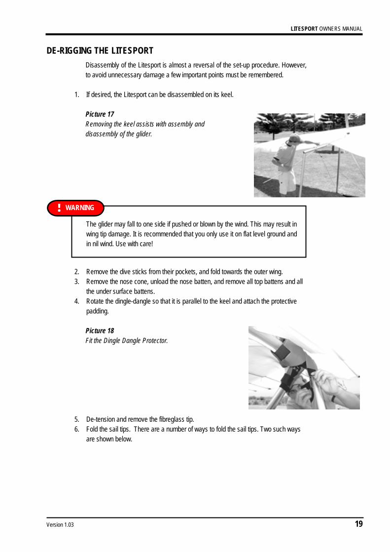
DE-RIGGING THE LITESPORT Disassembly of the Litesport is almost a reversal of the set-up procedure. However, to avoid unnecessary damage a few important points must be remembered.
1. If desired, the Litesport can be disassembled on its keel.
Picture 17 Removing the keel assists with assembly and disassembly of the glider.
2. Remove the dive sticks from their pockets, and fold towards the outer wing. 3. Remove the nose cone, unload the nose batten, and remove all top battens and all
the under surface battens. 4. Rotate the dingle-dangle so that it is parallel to the keel and attach the protective
padding. Picture 18 Fit the Dingle Dangle Protector.
5. De-tension and remove the fibreglass tip. 6. Fold the sail tips. There are a number of ways to fold the sail tips. Two such ways
are shown below.
The glider may fall to one side if pushed or blown by the wind. This may result in wing tip damage. It is recommended that you only use it on flat level ground and in nil wind. Use with care!
WARNING !
LITESPORT OWNERS MANUAL
20 Version 1.03
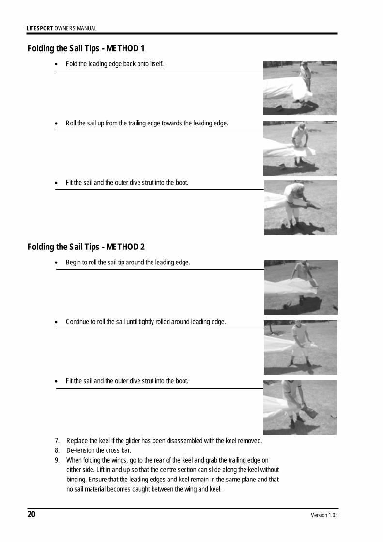
Folding the Sail Tips - METHOD 1 • Fold the leading edge back onto itself.
• Roll the sail up from the trailing edge towards the leading edge.
• Fit the sail and the outer dive strut into the boot.
Folding the Sail Tips - METHOD 2
• Begin to roll the sail tip around the leading edge.
• Continue to roll the sail until tightly rolled around leading edge.
• Fit the sail and the outer dive strut into the boot.
7. Replace the keel if the glider has been disassembled with the keel removed. 8. De-tension the cross bar. 9. When folding the wings, go to the rear of the keel and grab the trailing edge on
either side. Lift in and up so that the centre section can slide along the keel without binding. Ensure that the leading edges and keel remain in the same plane and that no sail material becomes caught between the wing and keel.
LITESPORT OWNERS MANUAL
Version 1.03 21
10. Pull down on the top side wires. This will lower the compensator at the top of the king post, allowing the king post to be lowered onto the sail.
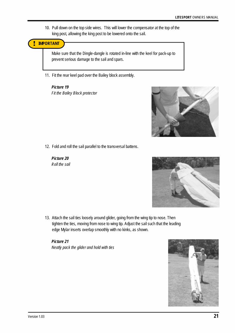
11. Fit the rear keel pad over the Bailey block assembly.
Picture 19 Fit the Bailey Block protector
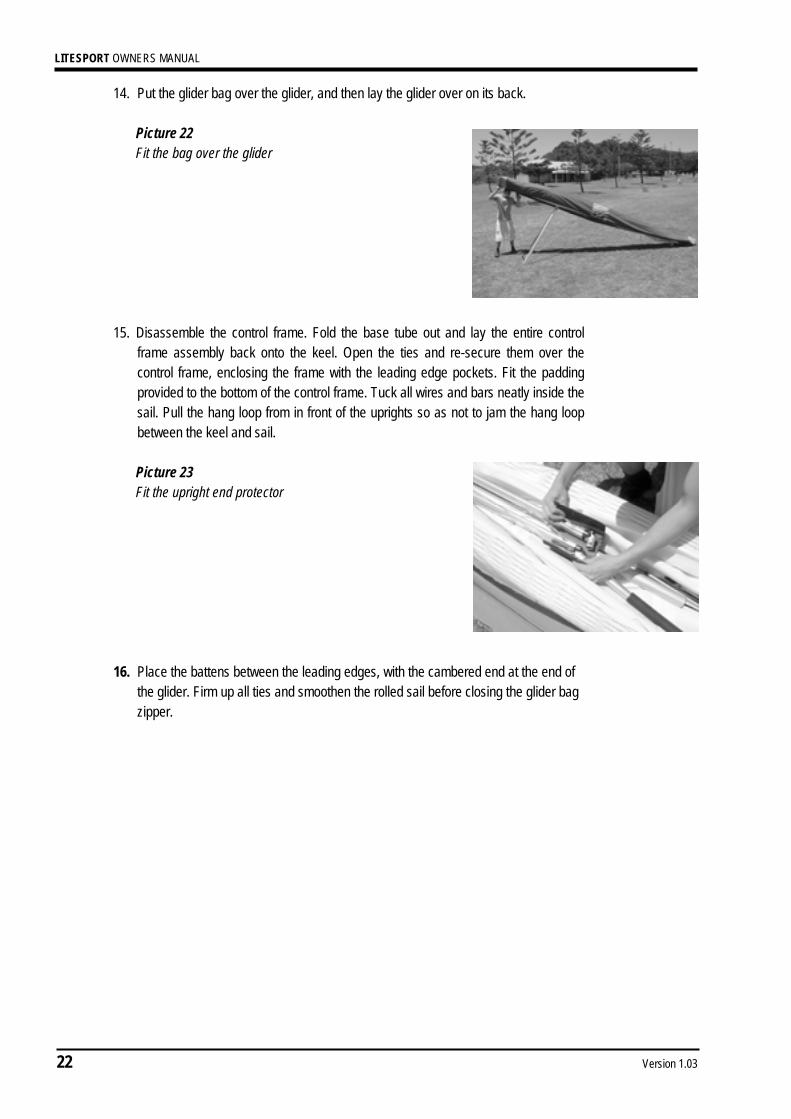
12. Fold and roll the sail parallel to the transversal battens.
Picture 20 Roll the sail
13. Attach the sail ties loosely around glider, going from the wing tip to nose. Then
tighten the ties, moving from nose to wing tip. Adjust the sail such that the leading edge Mylar inserts overlap smoothly with no kinks, as shown.
Picture 21 Neatly pack the glider and hold with ties
Make sure that the Dingle-dangle is rotated in-line with the keel for pack-up to prevent serious damage to the sail and spars.
IMPORTANT !
LITESPORT OWNERS MANUAL
22 Version 1.03
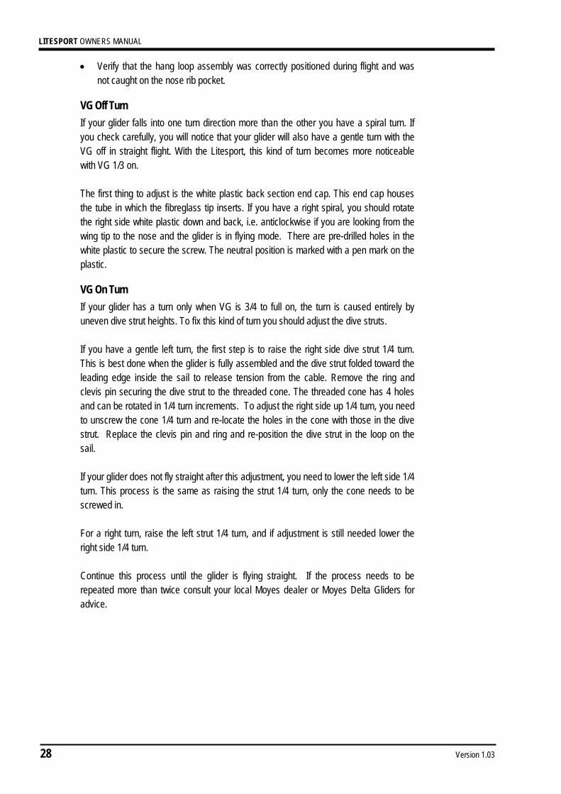
14. Put the glider bag over the glider, and then lay the glider over on its back.
Picture 22 Fit the bag over the glider
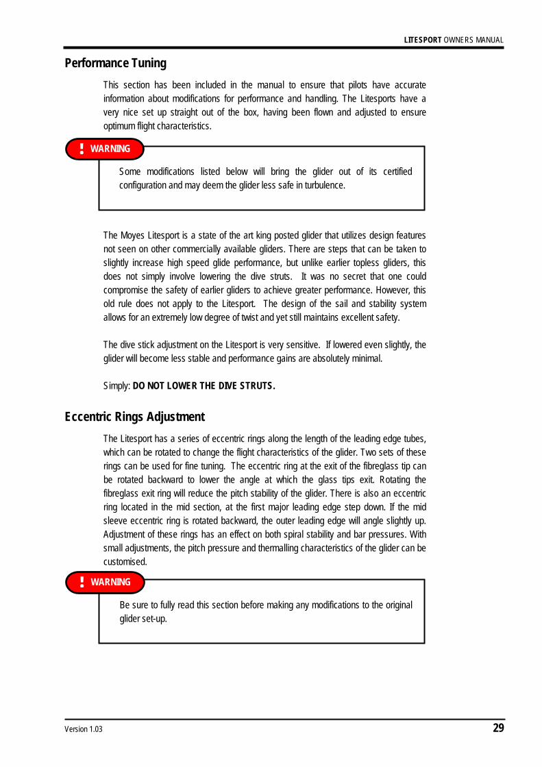
15. Disassemble the control frame. Fold the base tube out and lay the entire control
frame assembly back onto the keel. Open the ties and re-secure them over the control frame, enclosing the frame with the leading edge pockets. Fit the padding provided to the bottom of the control frame. Tuck all wires and bars neatly inside the sail. Pull the hang loop from in front of the uprights so as not to jam the hang loop between the keel and sail.
Picture 23 Fit the upright end protector
16. Place the battens between the leading edges, with the cambered end at the end of the glider. Firm up all ties and smoothen the rolled sail before closing the glider bag zipper.

LITESPORT OWNERS MANUAL
Version 1.03 23
FLYING THE MOYES LITESPORT
Take-Off The Moyes Litesport has a neutral static balance and therefore is very easy to launch in calm or windy conditions, and on steep or shallow slopes. The nose should be held slightly above parallel with the slope, with the wings level. Your run should be a smooth acceleration with appropriate pitch control. Once a safe air speed is reached, a slight easing out of the bar will give a smooth lift off. In winds in excess of 10-15 mph (16-24 kph), some wire assistance may be required.
Using the VG for Take-Off In some situations it is recommended to launch the glider with up to 1/3 VG. It is not advisable to use more than 1/3 VG, as the glider will become difficult to control if turbulence is encountered during or just after take off. In windy conditions, some VG can help the glider penetrate forward and away from the hill. With 1/3 VG the glider has a more solid feel and pilot induced oscillations are less likely. On the other hand, many experienced pilots prefer the loose VG setting during windy or turbulent take offs, to allow for maximum control authority. For your first windy take off on the Litesport, the 1/4 VG setting is recommended. For light or nil wind take offs, some VG can help the glider lift sooner, making launching easier. This is especially helpful for take offs on shallow slopes, as the glider’s increased performance will allow for a shorter take off run. It is important to note, however, that with more VG the glider becomes more prone to tip stalling. Therefore, if VG is used during take off, special care must be taken to keep the wings level and to achieve a safe launching airspeed. For cross wind take offs, a hang glider becomes much more vulnerable to tip stalling, so it is best to launch with the VG loose in these situations.
Litesport Variable Geometry The Moyes Litesport features a large VG range with a sail and frame construction that makes the system powerful and effective. The initial pull of the VG has the most significant effect on the sail tension. When the VG is half on, most of the washout has already been removed and with 1/2 to 3/4 VG the sail is already beginning to rest on the dive struts. The remaining 1/2 to 1/4 of the VG travel begins to take the washout out of the root and mid span. The additional sail tension has the effect of flattening the battens slightly, thus producing a better high speed airfoil. The Litesport features an enclosed VG system similar to recent Moyes gliders. The system of roller and pin bearings used allows the pilot to fine tune the wing with minimum effort.

LITESPORT OWNERS MANUAL
24 Version 1.03
Thermalling the Litesport
Bank Angle and Airspeeds The Litesport is designed to thermal comfortably at a bank angle of 30 degrees and with an airspeed 4mph (6kph) above stall speed. Reducing the airspeed further can improve the climb rate, but some high siding is required to maintain a shallow bank angle. The sink rate of the glider improves only very slightly if the airspeed is reduced to the limit and at such a low airspeed there is some loss of control authority. Therefore it is only recommended to thermal the glider on the stall limit in weak smooth thermals. In strong or turbulent conditions it is strongly recommended to fly with excess airspeed to maintain control and to avoid stalling in thermal gusts. One of the high points of the Litesport is its coordination at high bank angles. The glider can be banked to 50 or 60 degrees while maintaining a low sink rate with minimum pilot effort. As the bank angle is increased, little or no high siding is required, and at higher air speeds it may be necessary to roll in to maintain the bank angle. In order to coordinate a high bank angle, the control bar position needs to be pushed out slightly more than when thermalling at lower bank angles. It is recommended to pay special attention to the air speed indicator during the initial thermal flights on your Litesport.
Thermalling with VG It is possible to thermal the Litesport with up to 1/3 VG and experience a noticeable gain in climb rate. However, when the VG is pulled 1/3 tight the Litesport requires more high siding, especially at low bank angles. The roll response also decreases with increasing VG settings. Thermalling with VG is a trade off between handling and climb rate performance. Many top competition pilots choose to thermal the Litesport with VG off to save energy and provide faster roll rates. The glider will climb better with some VG but also becomes less comfortable and increasingly difficult to fly. In turbulent conditions it is recommended to fly with VG loose to maximise stability and control. Often this increase in control is more beneficial to climb rates as a pilot can easily centre and stay in the thermal core. There are situations when the Litesport is best thermalled with a small amount of VG, therefore we recommend that the pilot experiments with this to find what best suits him/her self.
Gliding the Litesport The greatest advantage of the Litesport is its glide performance, particularly at high speeds. A best glide ratio of 14:1 can be achieved in still air at low speed, 25mph (40 km/h) with a pilot in the middle of the weight range. However if a headwind is encountered, or high thermal strengths are expected, the pilot needs to fly at higher air speeds to maximise the flight performance.
VG Position for Gliding With the VG full on, the Litesport sail has as much tension as the Litespeed. The Litesport is intended to be tuneable for all situations, and with VG full tight the glider

LITESPORT OWNERS MANUAL
Version 1.03 25
becomes quite difficult to control. The full tight VG setting is only intended for high speed glides, and especially high speed diving into goal. At the lower end of the speed range there is little glide advantage to be had by flying with the full tight setting. Maximum glide will not change much from 3/4 VG to full tight. When floating along a ridge, or gliding slowly down wind, the pilot will find no advantage by flying full tight. The only consequence will be a loss of handling. However, if penetrating a strong wind, full VG will give the pilot a noticeable glide advantage and handling will be manageable due to the higher airspeed.
Safety in Turbulence A hang glider is a tailless aircraft and thus pitch stability tends to be less when compared to conventional aircraft. One of the design goals of the Litesport was to maximise the pitch stability. This was achieved with a strong rigid dive strut system and the G-string compensated luff line. Moyes are extremely satisfied with the strength and stability of the Litesport. However, the risk of a tuck or tumble still remains, if extreme turbulence is encountered. It is important that the pilot understands how to minimise this risk.
Airspeed Many experts believe that the most common cause of tumbling is a loss of airspeed due to turbulence. When the glider loses airspeed it becomes increasingly vulnerable to a tumble. The glider may hit a surge of lift, which raises the nose, and even if the pilot holds the control bar in position, the glider will climb and quickly lose airspeed. It is at this point that the glider is vulnerable to tumbling. It is therefore paramount that the pilot maintains sufficient airspeed in turbulence. If the glider hits a surge of lift, which raises the nose, the pilot should quickly react to bring the glider back into a normal flying attitude and restore the lost airspeed.
Body Position The most vital thing for a pilot to do in heavy turbulence is to maintain a strong grip on the control bar. The pilot remains safest when the control bar is held tight and close to the body at, or just below the pilot’s chest. If extreme turbulence is encountered, the pilot should apply a force pulling his/her body toward the base bar. This means that if a sudden weightless or negative G situation occurs, the pilot can stay pinned to the base bar, achieving a forward centre of gravity which greatly aids in producing a quick recovery.
VG in Turbulence Most high performance hang gliders produce a stronger positive pitch moment through negative angles with a loose VG setting, as opposed to a tight setting. The least amount of positive pitch moment generally occurs with the VG 3/4 tight. The Litesport’s compensator system allows this glider to produce a particularly strong pitching moment in the loose VG setting. If a significant amount of turbulence is encountered, it is best to release the VG or use 1/4 VG. While in the turbulence, make sure you keep a very firm grip on the control bar, and do not sacrifice this strong grip to release the VG. It is best to wait for a safe moment and then to release.

LITESPORT OWNERS MANUAL
26 Version 1.03
When leaving a strong thermal one can expect significant turbulence at the edge of the thermal. Many pilots like to pull 3/4 VG to allow more control over the glider in this turbulence, however it must be remembered that this is the VG setting, which produces the lowest positive pitch moment at negative angles. Many situations occur during regular flying when a pilot will enter pre-recognised turbulence, such as entering a strong thermal or entering the lee side of a mountain. The pilot can greatly increase his safety by entering this foreseen turbulence with an appropriate VG setting.
Flying the Litesport in Rain Flying in rain can cause significant changes to the behaviour of the glider. It is strongly advised that you avoid deliberately flying in rain. As water beads up on the leading edge, the stall characteristics of the wing begin to worsen. If rain is encountered, keep airspeed well above stall, especially near the ground. If the wing stalls, you may need to pull in significantly to lower the angle of attack enough to restore normal airflow. When landing, avoid any turns close to the ground, as a wet glider will lose significantly more height in a turn. Fly a faster final approach than normal, and be ready to flare aggressively as soon as the wing begins to stall.

LITESPORT OWNERS MANUAL
Version 1.03 27
TUNING HINTS It can be noted that the staff at Moyes are more than willing to provide advice or help in the tuning of your glider. Feel free to contact Moyes on:
Trim Adjustment Upon delivery your Litesport should have been test flown by a factory test pilot. Part of this test flight procedure includes trimming the glider. The designated CG location is measured from the front of the keel tube (this is the front of the tube exclusive of the end cap) and is 1390mm for the Litesport 4 and 1430mm for the Litesport 5. Before changing the trim position of your glider it is best to check where your hang point is in relation to the designated trim. Each hole position is equivalent to approximately a 1.5mph (2.4kph) change of trim speed. If you experience excessive pitch pressure while gliding with full VG, it could be that your trim position is too slow (too far rearward). Moving the trim forward one hole will cause a noticeable reduction of pitch pressure. Most competition pilots prefer to fly with a more rearward CG location. Pilots favour this as they can experience less push out pressure when circling and thus the glider becomes more comfortable to thermal. This lets the pilot fly with lighter pressures, allowing for more sensitivity to the moving air.
Fixing turns It is possible for a glider to develop a turn with age due to uneven stretch or uneven shrinking of the sail due to flying or UV exposure. It can be noted that Dacron materials are more vulnerable to stretch and shrinkage. If your glider develops a turn that previously did not exist, you should check the following: • Check the battens against the template and against each other, for accuracy and
symmetry • Remove and thoroughly check both leading edges for bends or damage • Carefully sight along the keel to check for any bends or damage • Check that no wires or thimbles are twisted, bent or kinked.
T: +61 (0)2 9316-6466 F: +61 (0)2 9316-8488 E: [email protected]
Never change the trim position of your glider upon delivery before test flying. All changes in trim position should be carried out in increments of 1 hole at a time.
IMPORTANT !
LITESPORT OWNERS MANUAL
28 Version 1.03
• Verify that the hang loop assembly was correctly positioned during flight and was not caught on the nose rib pocket.
VG Off Turn If your glider falls into one turn direction more than the other you have a spiral turn. If you check carefully, you will notice that your glider will also have a gentle turn with the VG off in straight flight. With the Litesport, this kind of turn becomes more noticeable with VG 1/3 on. The first thing to adjust is the white plastic back section end cap. This end cap houses the tube in which the fibreglass tip inserts. If you have a right spiral, you should rotate the right side white plastic down and back, i.e. anticlockwise if you are looking from the wing tip to the nose and the glider is in flying mode. There are pre-drilled holes in the white plastic to secure the screw. The neutral position is marked with a pen mark on the plastic.
VG On Turn If your glider has a turn only when VG is 3/4 to full on, the turn is caused entirely by uneven dive strut heights. To fix this kind of turn you should adjust the dive struts. If you have a gentle left turn, the first step is to raise the right side dive strut 1/4 turn. This is best done when the glider is fully assembled and the dive strut folded toward the leading edge inside the sail to release tension from the cable. Remove the ring and clevis pin securing the dive strut to the threaded cone. The threaded cone has 4 holes and can be rotated in 1/4 turn increments. To adjust the right side up 1/4 turn, you need to unscrew the cone 1/4 turn and re-locate the holes in the cone with those in the dive strut. Replace the clevis pin and ring and re-position the dive strut in the loop on the sail. If your glider does not fly straight after this adjustment, you need to lower the left side 1/4 turn. This process is the same as raising the strut 1/4 turn, only the cone needs to be screwed in. For a right turn, raise the left strut 1/4 turn, and if adjustment is still needed lower the right side 1/4 turn. Continue this process until the glider is flying straight. If the process needs to be repeated more than twice consult your local Moyes dealer or Moyes Delta Gliders for advice.
LITESPORT OWNERS MANUAL
Version 1.03 29
Performance Tuning This section has been included in the manual to ensure that pilots have accurate information about modifications for performance and handling. The Litesports have a very nice set up straight out of the box, having been flown and adjusted to ensure optimum flight characteristics. The Moyes Litesport is a state of the art king posted glider that utilizes design features not seen on other commercially available gliders. There are steps that can be taken to slightly increase high speed glide performance, but unlike earlier topless gliders, this does not simply involve lowering the dive struts. It was no secret that one could compromise the safety of earlier gliders to achieve greater performance. However, this old rule does not apply to the Litesport. The design of the sail and stability system allows for an extremely low degree of twist and yet still maintains excellent safety. The dive stick adjustment on the Litesport is very sensitive. If lowered even slightly, the glider will become less stable and performance gains are absolutely minimal. Simply: DO NOT LOWER THE DIVE STRUTS.
Eccentric Rings Adjustment The Litesport has a series of eccentric rings along the length of the leading edge tubes, which can be rotated to change the flight characteristics of the glider. Two sets of these rings can be used for fine tuning. The eccentric ring at the exit of the fibreglass tip can be rotated backward to lower the angle at which the glass tips exit. Rotating the fibreglass exit ring will reduce the pitch stability of the glider. There is also an eccentric ring located in the mid section, at the first major leading edge step down. If the mid sleeve eccentric ring is rotated backward, the outer leading edge will angle slightly up. Adjustment of these rings has an effect on both spiral stability and bar pressures. With small adjustments, the pitch pressure and thermalling characteristics of the glider can be customised.
Some modifications listed below will bring the glider out of its certified configuration and may deem the glider less safe in turbulence.
WARNING !
Be sure to fully read this section before making any modifications to the original glider set-up.
WARNING !
LITESPORT OWNERS MANUAL
30 Version 1.03
How to Adjust the Eccentric Rings The mid section ring can be adjusted freely with no consequence to safety of the glider. Do not rotate these rings beyond the existing pre-drilled holes, as more rotation is unnecessary and will not provide any advantage. All references to adjustments are made relative to the centre location. On the mid section rings, the centre location is the point where the marker screw aligns with the horizontal stopper screw. On the fibreglass exit ring, the centre location is the point at which the small pen mark on the back section aligns with the pen mark on the ring. The Litesport has been produced with several adjustment holes already drilled into the plastic rings. These pre-drilled holes allow for adjustments forward and backward from the centre location. Your Litesport may have been slightly adjusted after being test flown. To adjust the eccentric rings, it is best to remove the mid section and back section leading edge. Before attempting this, it is best to consult the relevant assembly drawing in this manual. Remove the sail retaining clevis pin at the back section end, and the 3/16 pin (or possibly bolt), which acts as a stopper for the back section and secures the mid section. There is a small screw which locates the mid section eccentric ring, this will also need to be removed. Once this is completed, the mid section and back section can be removed through the sail inspection zipper. After the mid section and back section have been removed, you can take a close look at your current set up and assess what adjustments are desired. There is no optimal set up; it simply comes down to personal choice. If you find too much high siding is required, you can rotate the mid section rings as many as two holes backward. It is best to make small adjustments, as the eccentric rings are very sensitive.
Set Up Suggestions For pleasant thermalling, a good combination is to have the mid section rings one hole backward (outboards angled slightly upwards) and the fibreglass exit rings in the centre location. Some gliders leave the factory with this set up, so this may be your starting point.

LITESPORT OWNERS MANUAL
Version 1.03 31
GLIDER CARE Your Moyes Litesport will require very little maintenance if you take extra time and care with your daily treatment and use of your glider.
Storage Keep the glider in its bag, in a cool dry place. Store the glider off the floor or ground and free from contact with oils, solvents, or acidic substances. Always dry the glider completely before storing. If this is not possible, ensure that the glider bag is off or open and that the sail is loose enough for air to circulate. Dry the glider completely, as soon as possible.
Sail Care It is important to keep the sail clean and free from salt if you fly near the coast. Regular rinsing with fresh water will achieve this. For more thorough washing, a mild detergent may be used provided it is completely rinsed off the sail. For more serious stains, consult your local sail maker or Moyes agent. Always ensure that all protective padding is properly placed for transport or pack up. Even one short trip with missing or incorrectly located padding is enough to wear a hole in the sail. For small tears, apply sail repair tape to prevent fraying. Unless the tear is at a stress point or along the trailing edge it will not tend to run or expand. Sun and exposure to the elements will deteriorate the sail more rapidly than hours of flying. It is important to minimise exposure to UV radiation. If possible, set up the glider in the shade and minimise the time that the glider is left open to the elements. Dacron or Powerib sails are considerably more vulnerable to UV deterioration than the new PX Mylar. It is important to carry the glider in its bag, on well padded roof bars, with at least three points of support. If you take just a little extra care when packing up and transporting your glider, it will maintain its condition and performance for many more enjoyable hours.
Battens Never force the battens into their pockets. Insert them gently to avoid damage to the sail and wear to the batten ends. If battens are pushed into the pockets too quickly the plastic batten ends will heat to the point of slightly melting and create unnecessary wear on the batten pockets. Sand in the sail or on the battens will cause abrasion in the pockets. Always pack the highly cambered battens into the batten bag as a unit, never one at a time. This will avoid flattening the battens. Store the battens securely between the rear leading edges with the camber to the very end of the glider, so that the glider rack ties do not pull across the camber.

LITESPORT OWNERS MANUAL
32 Version 1.03
Wires and Attachments Wires should be replaced at the first sign of fraying, kinking or damage. Stainless steel cable tends to work harden, especially where it enters or exits a Nico sleeve. The shrink tube covering the Nico sleeve should be peeled back periodically to inspect the cable. Setting up on rough or rocky ground will shorten the rigging’s life. Wires are not expensive and are easy to replace, and yet they are critical to the glider’s structural integrity. If the glider is periodically exposed to salty air, some oxidation may form on the cable. This is nothing to be concerned about as it is only caused by impurities in the cable material.
Tubing Contact with salt air or water is a major concern and will require the removal of the end caps and a thorough flushing and drying. Follow the maintenance schedule conscientiously. Examine the tubes for dents, bends, wear spots, and corrosion, during every pre-flight. If any damage is noticed, replace the tube, but also determine how that damage was caused and take steps to prevent the damage form re-occurring.
Hardware and Bolts Bolts can be bent in a crash or hard landing. These should be replaced. All bolts should show exposed thread pass the nuts.
Note to Coastal Fliers The Litesport uses thin walled 7075T6 tubing throughout the airframe, which is considerably more vulnerable to corrosion than the 6061 alloy used on previous gliders. If any tubing is ever directly exposed to salt water it must be thoroughly rinsed with fresh water as soon as is possible. If your glider is exposed to coastal air, you must rinse the inside and outside of the tubes with fresh water once every six months. If your glider is stored near the coast you need to keep your glider in a dry location such as a closed garage. It is possible to put a film of linseed oil on the inside of the leading edge tubes. This will help prevent corrosion. Fully disassemble the leading edges, removing all sleeving. Pour a small amount of linseed oil into each tube and sleeve, rotating the tubes as you pour, to entirely coat the inner wall. After this is done, apply a second coat by wetting a cloth with linseed oil, attaching it to a broomstick, and pushing it through the length of the tube. Note that the front section leading edge has a series of inner nylon rings, thus the cloth must be pushed through each end individually.
Never try to straighten a bent bolt. Straightening the bolt will cause significant work hardening and will dramatically reduce strength. All Moyes hang gliders use specially sourced aircraft quality bolts throughout the airframe, and should only be replaced by the exact bolt type available from your local Moyes Dealer.
IMPORTANT !

LITESPORT OWNERS MANUAL
Version 1.03 33
MAINTENANCE SCHEDULE
Every l0 Hours 1. Check all battens against the airfoil template. 2. Sight through the sail zippers to inspect for any tube dents or bends.
Every 50 Hours (or biannually) 1. Inspect the sail for wear and damage. Check the stress areas and apply sail repair
tape where necessary. Special attention should be directed to the wire slots. 2. Inspect all batten flip tips. 3. Inspect all cross bar wires, fittings, and hardware. 4. Check all tubing for damage or wear caused by set up, pack up, or transportation. 5. Inspect all rigging for frays and other signs of damage or deterioration. Replace if
necessary. 6. Replace the lower side wires.
Every 100 Hours (or annually) This inspection is best carried out by your local Moyes dealer or the Moyes factory. The sail must be removed, allowing for all components to be exposed and thoroughly examined. Check the sail for any wear or abrasion. Small holes in low stress areas such as the undersurface can be repaired with sail repair tape. Damage in higher stress areas such as the trailing edge or centre seam need to be fixed by a professional sail maker. It is best to contact your local dealer or consult Moyes directly about the repair of sail damage. Thoroughly inspect all tubing for dents, bends, and corrosion and replace when necessary. All bolts should be examined closely for wear and bends. Remove all cross bar junction bolts and the A-frame top bolt and closely examine for bends and corrosion. Replace all parts that show damage. Replace the top side wires every 100 hours.
LITESPORT OWNERS MANUAL
34 Version 1.03
SAIL REMOVAL We suggest that you do not attempt to remove the sail if you are not familiar with this procedure. Contact your nearest Moyes dealer for assistance. 1. Lay the glider flat on the ground, unzip the glider bag, roll the glider over so that it is
top side up, remove all the ties, and spread the wings a few feet. 2. Remove the sail attachment screws from the nose of the glider and rear of keel
pocket. 3. Undo the central zipper entirely and remove the plastic cable tie at the nose of sail. 4. Disconnect the luff line and undo the clevis pin on both sides to release the top side
wires from the leading edges. 5. Disconnect the bottom side wires from the bottom of the down tubes by unscrewing
the hinge pin. Be sure not to lose any of the hardware during the process. 6. Disconnect the rear wires from the keel by undoing the Bailey block bolt. 7. Open the tip zippers and disconnect the sail attachment straps from the clevis pins
at the end of each leading edge. 8. Carefully slide the frame forward and out of the sail. To re-mount the sail, reverse the process by which it was removed. All Velcro straps attaching the top and bottom surfaces must be overlapped their full length.

LITESPORT OWNERS MANUAL
Version 1.03 35
CHECKING THE LITESPORT STABILITY SYSTEM
Step One
Step Two
Step Three
Step Four
Option One Hang the glider from three points to simulate its flying position. The three positions are; 1. the keel behind the rear wires, 2. the left side wing where the bottom
side wire exits the sail, and 3. the right side wing where the bottom
side wire exits the sail. Option Two An alternative to hanging the glider is to raise the glider by using three support structures, such as ladders. With the VG system fully applied, tie a piece of thin thread between the two number nine batten ends, ensuring the string it taut. The string should be positioned under the keel. Obtain the correct measurement for your glider from the table below. Measure the distance between the string and the bottom of the keel. a = Distance between bottom of keel and
string b = Outer diameter of keel (42mm) c = a + b (obtain the correct distance
from the table on the next page)
For example, if your measurement is 95mm below the top of the keel. Therefore;
c = 95 b = 42 a = 95 – 42 = 53
Release the VG tension and adjust the dive struts until the correct measurement is obtained.
Keel Tube
Ruler
String
c
a
b

LITESPORT OWNERS MANUAL
36 Version 1.03
AN Bolt Index
Model VG Setting Batten Numbers 5 6 7 8 9 10
Litesport 4 Zoom Tight Standard Tight
Litesport 5 Zoom Tight Standard Tight
All measures are taken from the top of the keel, if string line falls below the keel, measure from bottom of keel and add the diameter of the keel (42mm).
IMPORTANT !
Measurements are the same for both Mylar and Dacron models.
NOTE !
STEP TWO: Align Bolt Head Under surface here.
STEP ONE: Determine bolt diameter.
3/16 1/4 5/16
Number at end of bolt is A.N. Dash Number (eg. AN4-10A)
AN3 AN4 AN5
4344
45
4241
4037
3635
3433
3231
3027
2625
2423
2221
2017
1615
1413
1211
107
65
43

LITESPORT OWNERS MANUAL
Version 1.03 37
PURCHASE RECORD Please complete this section for future reference.
Glider Model and Size
Purchase Date
Serial Number
Moyes Dealer (purchased from)
Dealer Address
MAINTENANCE LOG
Date Work Completed By
LITESPORT OWNERS MANUAL
38 Version 1.03
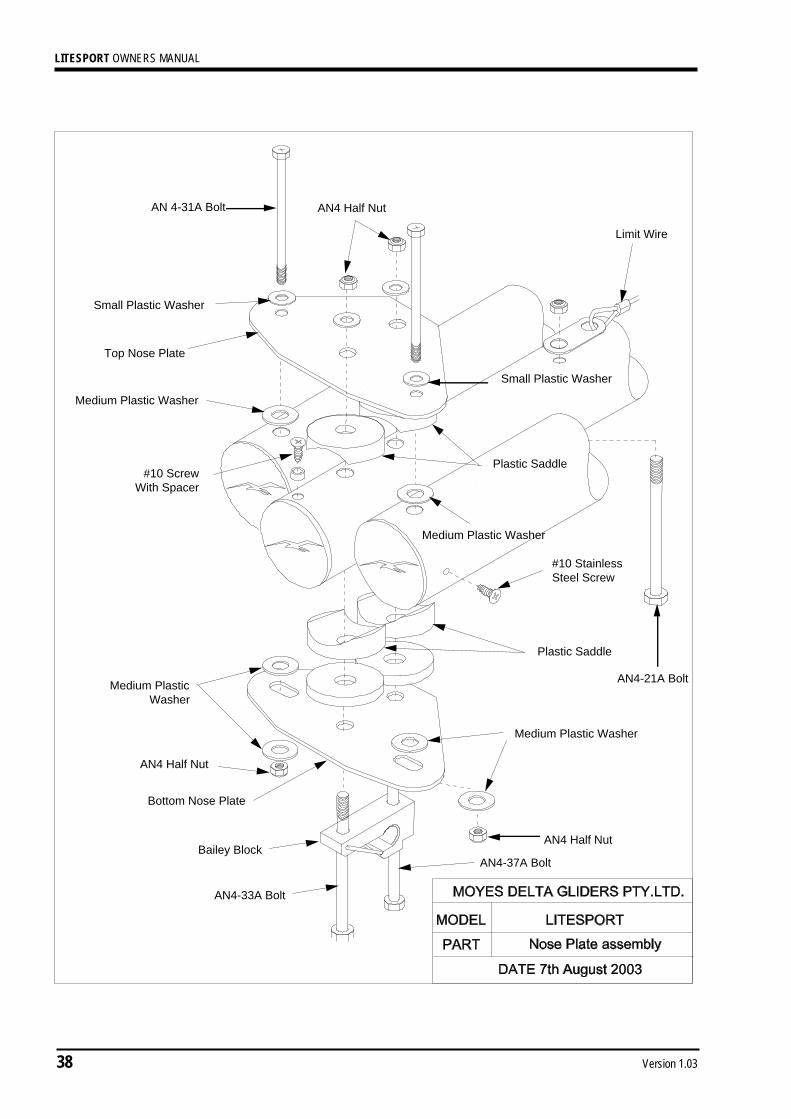
AN4 Half Nut
Limit Wire
AN 4-31A Bolt
Small Plastic Washer
Medium Plastic Washer
#10 StainlessSteel Screw
AN4 Half Nut
Bottom Nose Plate
Bailey BlockAN4 Half Nut
Medium Plastic Washer
Medium PlasticWasher
#10 ScrewWith Spacer
AN4-33A Bolt
Small Plastic Washer
Top Nose Plate
Medium Plastic Washer
Plastic Saddle
Plastic Saddle
AN4-21A Bolt
AN4-37A Bolt

LITESPORT OWNERS MANUAL
Version 1.03 39

LITESPORT OWNERS MANUAL
40 Version 1.03
WasherAN5 Full Nut
Keel KnuckleUpright
PMAEP Pin
Medium Plastic Washer
Upright Tube
Upright TubePMAEP Pin
Knuckle KeelUpright
Dingle-Dangle Base
Teflon PadDingle-Dangle Bottom
Dingle-Dangle Top
AN5 Half Nut
AN4 Half Nut
Pulley
5/32" Screws
Keel Tube
AN4-31A Bolt
AN4-12A bolt
AN5-34A Bolt
Plastic Spacers,Towed In
Plastic Spacers,Towed In
AN4 Half Nut
Note: Suspension strapmust be on the outside ofthe pullback rope. Back upstrap must be wrappedaround the keel and behindthe dingle dangle.
Stainless SteelSpacers 4mm
AN5-31A Bolt
RF20151A Pulley
Plastic Sleeve

LITESPORT OWNERS MANUAL
Version 1.03 41

LITESPORT OWNERS MANUAL
42 Version 1.03

LITESPORT OWNERS MANUAL
Version 1.03 43

LITESPORT OWNERS MANUAL
44 Version 1.03
LITESPORT OWNERS MANUAL
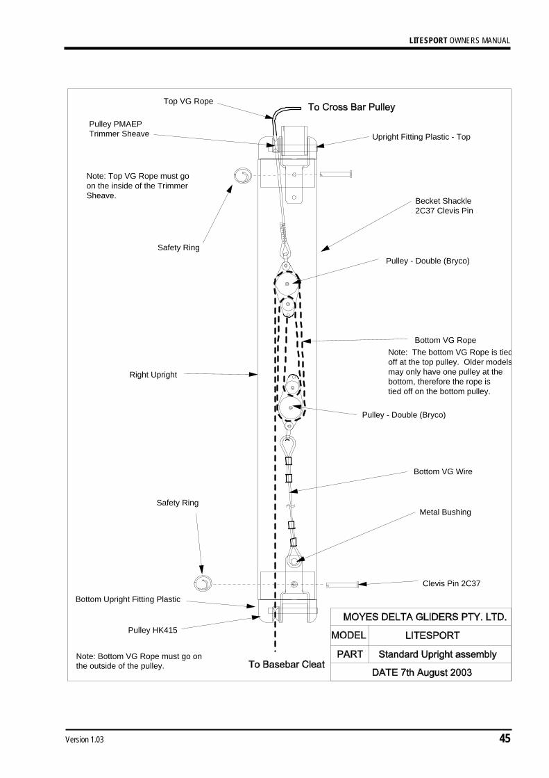
Version 1.03 45
Becket Shackle2C37 Clevis Pin
Upright Fitting Plastic - TopPulley PMAEPTrimmer Sheave
Top VG Rope
Bottom VG Rope
Metal Bushing
Bottom Upright Fitting Plastic
Right Upright
Note: Top VG Rope must goon the inside of the TrimmerSheave.
Note: Bottom VG Rope must go onthe outside of the pulley.
Pulley - Double (Bryco)
Pulley - Double (Bryco)
Safety Ring
Safety Ring
Clevis Pin 2C37
Bottom VG Wire
Pulley HK415
Note: The bottom VG Rope is tiedoff at the top pulley. Older modelsmay only have one pulley at thebottom, therefore the rope istied off on the bottom pulley.
LITESPORT OWNERS MANUAL
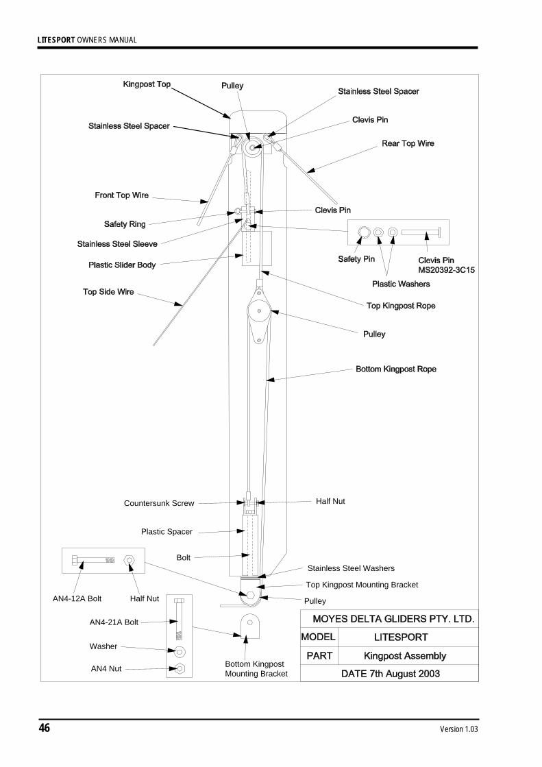
46 Version 1.03
AN4-21A Bolt
Washer
AN4 Nut
Half Nut
AN4-12A Bolt Half Nut
Bottom KingpostMounting Bracket
Pulley
Top Kingpost Mounting Bracket
Stainless Steel WashersBolt
Plastic Spacer
Countersunk Screw
LITESPORT OWNERS MANUAL
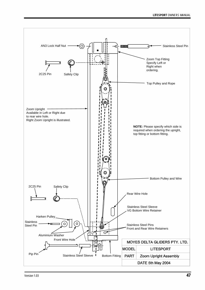
Version 1.03 47
Zoom UprightAvailable in Left or Right dueto rear wire hole.Right Zoom Upright is illustrated.
Stainless Steel PinAN3 Lock Half Nut
2C25 Pin Safety Clip
Top Pulley and Rope
Bottom Pulley and Wire
Zoom Top FittingSpecify Left orRight whenordering.
2C25 Pin Safety Clip
Bottom Fitting
StainlessSteel Pin
Harken Pulley
Aluminium Washer
Stainless Steel Sleeve
Stainless Steel PinsFront and Rear Wire Retainers
Stainless Steel SleeveVG Bottom Wire Retainer
Rear Wire Hole
Pip Pin
Front Wire Hole
NOTE: Please specify which side isrequired when ordering the upright,top fitting or bottom fitting.