live demonstration of lrfd simon 3-span bridge
TRANSCRIPT

Photo: 2020 Prize Bridge National Winner, Major Span – Gov Cuomo/Tappen Zee (New York) – Photo Credit: New York State Thruway Authority
Live Demonstration of LRFD Simon 3-Span BridgeDevin Altman, PE – Bridge Steel Specialist (Steel Solution Center)
Steel Bridge Essentials: 6 Part Summer Webinar Series – Part 2

Learning Objectives
• Understand how to develop the required inputs for LRFD Simon and your bridge
• Learn how to use the LRFD Simon User’s Guide for further clarification when needed
• Understand how to interpret LRFD Simon output and increase resistance if needed
• Learn about LRFD Simon in general and when it is appropriate for design/analysis and when it is not
• Understand how to use NSBA Continuous Span Standards as a starting point

Continuous Span Standards
• Example steel girder design drawing detail/spec
• 5 girder bridge cross-sections with balanced design
• Per AASHTO LRFD BDS 7th Edition (update out soon)
LRFD Simon
• Line girder analysis software
• Design mode, analysis mode, web depth optimization
• Per AASHTO LRFD BDS 8th Edition (update out soon)
Overview of the Design Tools Used Today

Where Can I Find These Free Design Tools
https://www.aisc.org/nsba

➢ LRFD Simon input files included
➢ Flange plate sizes and lengths
➢ Web plate sizes and lengths
➢ Diaphragm spacing
➢ Stiffener locations
➢ Girder weights
➢ Shear connector spacing
➢ Camber tables
Continuous Span Standards
• Assist Engineers During the TS&L Phase:

Continuous Span Standards
• Center Span: 150 ft – 300 ft
• End Spans: 78% of center span
• Girder Spacing: 7ft – 6in to 12ft – 0in
• Homogeneous and hybrid solutions
• Web depth to suite material efficiency
• AASHTO 7th Edition LRFD
• 88 Unique Solutions
Preliminary designs include:

LRFD Simon
Analysis and Design Program
• Powerful Line-Girder Analysis & Design Software
• I-Girder and Box Girders Bridges
• Linear and Parabolic Haunches
• AASHTO LRFD Bridge Design Specification – 8th Edition (9th
Edition LRFD Simon update coming later this summer)
• Straight Bridges with Minimal Skew

LRFD Simon
Analysis and Design Program
• Independently Design & Analyze both Interior and Exterior Girders
• Capable of Modeling Various Bridge Geometries and Design Loading Configurations
• Generates Service and Strength Moments, Shears, Deflections, and Bearing Reactions
• Helpful User’s Guide Manual Written by Mike Grubb & Associates

Keep in Mind Before We Get Started
Span Layouts
• Try to layout span arrangements with maximum positive moments being nearly equal in each span
• End spans ideally 75% - 82% of center span
Balanced Span Arrangement
0.75L To 0.82L 0.75L To 0.82LL

Keep in Mind Before We Get Started
Girder Spacing & Deck Overhangs
• Total factored moment tends to be larger in exterior girders
(subject to lateral bridge deck overhang truck impact loads)
• Limit size of deck overhangs accordingly
s(typ)
0.28s - 0.35s

Simple Spans 0.040L
Continuous spans 0.032L
Proportioning – Web Depth
• Optional Span-to-Depth Ratio (AASHTO BDS Section 2.5.2.6.3)
Suggested Minimum Overall Depth for Composite I-beam
DECK
Simple Spans 0.033L
Continuous spans 0.027L
Suggested Minimum Depth for I-beam
Keep in Mind Before We Get Started

Proportioning – Web Thickness
• Web Thickness (AASHTO BDS Section 6.10.2.1)
• ½" minimum thickness preferred by fabricators
Without Longitudinal Stiffeners
With Longitudinal Stiffeners
𝐷
𝑡𝑤≤ 150
𝐷
𝑡𝑤≤ 300
Dtw
Keep in Mind Before We Get Started

Proportioning - Flanges• Proportioning Requirements (AASHTO BDS Section 6.10.2.2):
12t2
b
f
f
6
Db f
10I
I1.0
yt
yc
Fabricators prefer: bf ≥ 12 in.; tf ≥ 0.75 in.
t f 1.1 tw
D
bf
tf
bf
D
tf
tw
Keep in Mind Before We Get Started

Field-Section Lengths for Steel I-Girders
• Shipment by truck is the most common means– 215 ft. Possible, 80 ft. Comfortable, 80 – 120’ typical
– Over 100 Tons Possible (20 Tons - No Permit)
– 16 ft. Width and 10 ft. Height (depending on truck and route)
– Girder under 9’ deep can usually be shipped vertical to anywhere
Keep in Mind Before We Get Started

3-Span Continuous Example
LRFD SIMON

What if Your Span Layout is This?
The Continuous Span Standards Come with LRFD Simon Inputs
165’ 165’200’

What if Your Cross-Section is This?
The Continuous Span Standards Come with LRFD Simon Inputs

Everything is Different Should I Start Over?
No, But We Still Need to Do the Hard Work and Develop the Design
• Generate Load Demands
• Compare Continuous Span Standards Loading Assumptions with Project
• Does Superstructure Depth Work for Project Constraints
• Overhang:Girder Spacing = 0.25 (Lower than Ideal)
• Verify and Check Everything

Grab LRFD Simon File Similar to Your Bridge
Our Girder Material is ASTM A709 50W, Homogeneous (Not Hybrid)

Design Girders with Project Design Criteria
I Recommend Using Excel or MathCAD Spreadsheet for Girder Design

General Properties – Exterior Girder
Vet & Update LRFD Simon Inputs for Project Requirements
Bridge Layout
Design Parametersand Boundaries
Deck Properties
Run Type
Fatigue Parameters

Distribution Factors – Exterior Girder
Vet & Update LRFD Simon Inputs for Project Requirements
User Defined or Program Defined
Calculated based on AASHTO BDS
Calculated manually:
LLDFM_SL = 0.858 lanesLLDFM_ML = 0.938 lanesLLDFS_SL = 0.858 lanesLLDFS_ML = 0.938 lanes
Define Interior or Exterior

Distribution Factors – Exterior Girder
AASHTO LRFD BDS Special Analysis (C4.6.2.2.2d - Commentary)
• Assuming the entire cross-section rotates as a rigid body about the longitudinal centerline of the bridge, distribution factors for the exterior girder are also computed for one, two and three lanes loaded using the following formula
• SIMON does NOT compute this LLDFcurrently, but will with the update coming later this summer
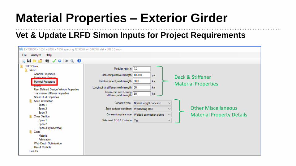
Material Properties – Exterior Girder
Vet & Update LRFD Simon Inputs for Project Requirements
Deck & Stiffener Material Properties
Other Miscellaneous Material Property Details

Loads –DC2 Distributed Evenly to Girders
Vet & Update LRFD Simon Inputs for Project Requirements
Composite Dead Loads (DC2)
Live Load Design Criteria

User Defined Vehicle (None for Example)
Up to 40 Axles for Strength II Permit/Superloads/Emergency Vehicles

Transverse Stiffener – Exterior Girder
Vet & Update LRFD Simon Inputs for Project Requirements
LRFD Simon Calculates if Left Blank
1 or 2 Sided Transverse Stiffeners?

Shear Studs – Exterior Girder
Vet & Update LRFD Simon Inputs for Project Requirements
LRFD Simon Designs the Shear Studs for You, Define the Shear Stud Geometrics and Concrete Modulus of Elasticity Used for Design

Span Information – Span 1
Span and Non-CompositeUniform Dead Load (DC1)
Top Flange Bracing
Bottom Flange Cross-Frame Spacing
Construction Lateral Moment Applied to Top & Bottom Flanges (Overhang)

Span Information – Span 2
Span 2 Length = 200 ft
Top Flange Cross-Frame spacing (Positive Moment)
Bottom Flange Cross-Frame Spacing (Negative Moment)
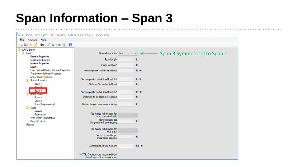
Span Information – Span 3
Span 3 Symmetrical to Span 1

Cross Section Data – Span 1 – Web

Cross Section Data – Span 1 – Top Flange

Cross Section Data – Span 1 – Bott. Flange

Cross Section Data – Span 1 – Deck Slab

Cross Section Data – Span 1 – Field Splice

Cross Section Data – Span 1 – Deck Pours

Cross Section Data – Span 2 – Web

Cross Section Data – Span 2 – Top Flange

Cross Section Data – Span 2 – Bott. Flange

Cross Section Data – Span 2 – Deck Slab

Cross Section Data – Span 2 – Field Splice
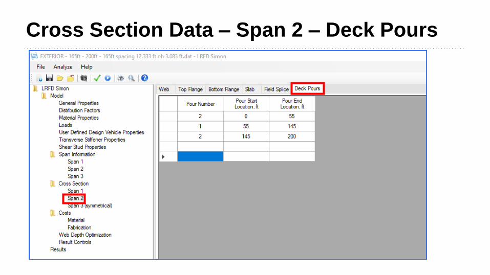
Cross Section Data – Span 2 – Deck Pours

LRFD Simon – Run the Analysis
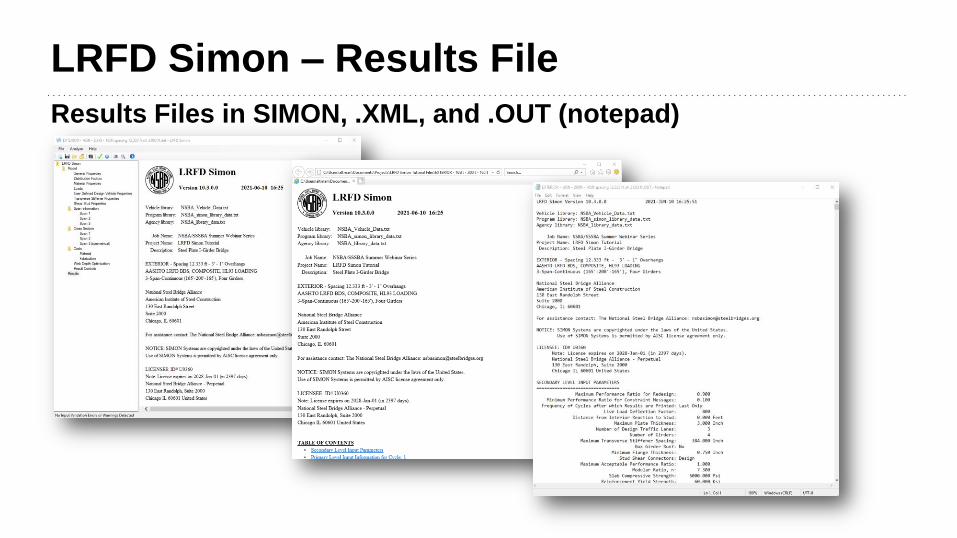
LRFD Simon – Results File
Results Files in SIMON, .XML, and .OUT (notepad)

LRFD Simon – Results Review
Moments Results

LRFD Simon – Results Review

LRFD Simon – Results Review
Shear Results

LRFD Simon – Results Review

Simon – Web Depth Optimizer (Design Mode)
Web Depth Optimization Parameters
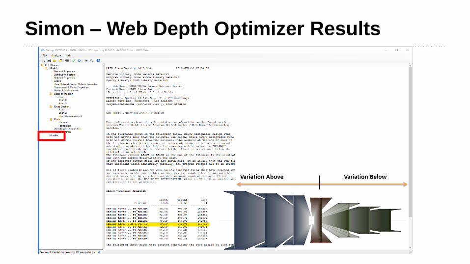
Simon – Web Depth Optimizer Results

LRFD Simon – Results Review
All Performance Ratios Should Be Less Than 1.0
• Highest P.R. is 0.956
• Verify Interior Girder Design is Adequate
• Could Refine Further to Optimize Sections for Fabrication and Costs
• If Results P.R. More Than 1.0, Revise & Rerun
• Adjust Web Thickness and Stiffeners for Shear
• Adjust Flange Thickness & CF Locations for Flexure & Fatigue

LRFD Simon Design Results
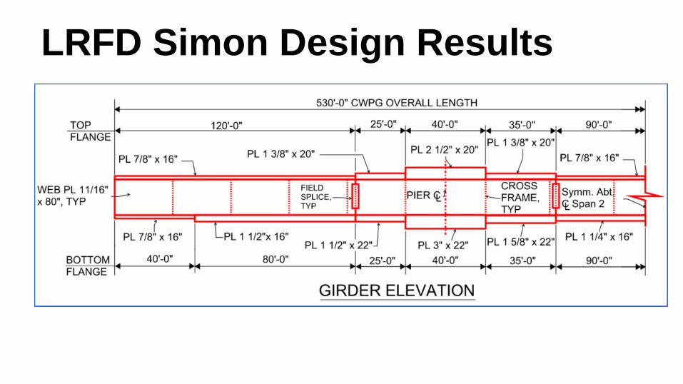
LRFD Simon Design Results