live partition mobility for oracle rac · 7/27/2001 · live partition mobility (lpm) is a feature...
TRANSCRIPT
LPM for Oracle RAC concepts http://www.ibm.com/support/techdocs © Copyright 2011, IBM Corporation
1
Live Partition Mobility for
Oracle RAC
Concepts and Recommendations
Francois Martin [email protected] Frederic Dubois [email protected]
IBM Systems and Technology Group
IBM Oracle Center (France) July 2011
LPM for Oracle RAC concepts http://www.ibm.com/support/techdocs © Copyright 2011, IBM Corporation
2
Table of contents
Abstract........................................... .......................................................................................... 3
Introduction ....................................... ....................................................................................... 3
Prerequisites...................................... ....................................................................................... 4
Checklist to enable Live Partition Mobility ........ ..................................................................... 4
Test Environment Example........................... ........................................................................... 5 Infrastructure...................................................................................................................................... 5
Prerequisites for the SAN Infrastructure........................................................................ 8 Prerequisites for the LAN Infrastructure .......................................................................11
Database ..........................................................................................................................................12 Client Workload simulated during the LPM operation.........................................................................12
Unsupported LPM operation for Oracle RAC for testin g ..................................................... 14
Supported LPM operation for Oracle RAC............. ............................................................... 16 Client configuration of the Transparent Application Failover (TAF) for continuous operation...............20
Real example of the LPM process ...............................................................................22 Server configuration of the Single Client Access Name (SCAN) listener ............................................27
Conclusion......................................... ..................................................................................... 28
Resources.......................................... ..................................................................................... 29
About the authors.................................. ................................................................................. 29
Appendix : Live Partition Mobility details ......... .................................................................... 30 Components .....................................................................................................................................30
Migration's steps:.........................................................................................................30 Partition state......................................................................................................... 30
Mover service partition and VASI ......................................................................................................31 RMC .................................................................................................................................................33 DLPAR-RM.......................................................................................................................................33
Making Programs DLPAR-Aware Using DLPAR AP.....................................................34 Reliable Scalable Cluster Technology (RSCT) authentication.......................................35
The RSCT authorization process in detail ..................................................................... 35 POWER Hypervisor.....................................................................................................38 Time reference partition (TRP).....................................................................................38
Conclusion........................................................................................................................................39 Trademarks and special notices ..................... ...................................................................... 40
LPM for Oracle RAC concepts http://www.ibm.com/support/techdocs © Copyright 2011, IBM Corporation
3
Abstract
This paper documents the concept and recommendation of using Live Partition Mobility (LPM) in an Oracle RAC environment.
It describes the configuration of the IBM Power systems infrastructure and Oracle RAC to perform the Live Partition Mobility of an Oracle RAC node.
The paper describes two scenarios, the first is given as example for test purpose in order to setup the configuration and understand the interaction of all components.
The second scenario is the officially supported LPM process for an Oracle RAC environment.
This paper is illustrated with a real example of the LPM of a RAC node from a Porwer6 processor based source server to a Power7 target server.
Introduction
Live Partition Mobility (LPM) is a feature of PowerVM Enterprise Edition which allows for moving an LPAR from an IBM Power system to another physical IBM Power system.
LPM increases availability of the application and improves workload management. LPM improves flexibility of the entire infrastructure as you are able to continuous run the applications during planned maintenance of your server, by migrating without disruption the logical partitions to another server. Also you are able to easily manage the applications workload by migrating LPARs and get free CPU and Memory resources for your most important workload production running on the source server.
Both source and target systems can be POWER6 or POWER7 processor based. The I/O adapters configured in the AIX LPAR must be defined as virtual devices and requires that the network and the SAN disk be accessed though a Virtual I/O Server Partition. LPM feature is not compatible with physical resources, so they have to be removed at least for the LPM operation, and if any, reattached to the LPAR after the migration.
Remember that you can keep physical adapters configured in the LPAR and also configure virtual adapters as a backup path for the network access and heterogeneous multi-path for the SAN disk access.
Also all the disks have to be defined from the SAN and shared to VIO servers of both source and target servers.
LPM process consist of several steps, such as reading the LPAR configuration on the source server to create it on the target server, creating the virtual devices at the target VIO Server, copying the physical memory blocks from the source to the target server, activating the LPAR on the target server and starting the AIX processes on the target server partition.
Once the processes are running on the target server partition, the virtual devices corresponding to the LPAR are removed from the source VIO Server and the LPAR is deleted on the source server.
The major migration step is the copy of the logical memory blocks (LMBs) though the network while AIX processes are running. At the end of the memory copy, almost 95%, a checkpoint operation is done and the processes are run from the target server. Depending on the amount of memory assigned to the LPAR and on the memory activity of the running processes, this checkpoint operation may freeze the processes for a short duration.
LPM for Oracle RAC concepts http://www.ibm.com/support/techdocs © Copyright 2011, IBM Corporation
4
You can find LPM discussion and advanced technical details at:
http://www.redbooks.ibm.com/abstracts/sg247460.html
From an Oracle RAC environment point of view, this step is the most critical and requires some certification tests. That is the reason why as the time of writing, LPM is supported for Oracle single instance database and Oracle RAC is not officially supported.
In the following you will see a functional example of LPM operation in Oracle RAC environment, so you can run it as a test without support from both IBM and Oracle.
The supported process for LPM operation in an Oracle RAC environment consists in stopping Oracle for the migration step while keeping AIX alive.
Prerequisites
This paper assumes the reader is aware of PowerVM™ virtualization technologies on IBM System p servers. For more information on PowerVM™ architecture please refer to “PowerVM™ Virtualization on IBM System p: Introduction and Configuration Fourth Edition”.
It is also assumed that the reader is familiar with Oracle Real Application Cluster (RAC) fundamentals and Oracle Database basic administration tasks.
Checklist to enable Live Partition Mobility
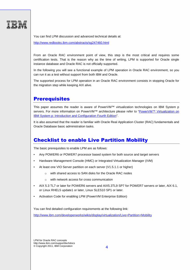
The basic prerequisites to enable LPM are as follows:
• Any POWER6 or POWER7 processor based system for both source and target servers
• Hardware Management Console (HMC) or Integrated Virtualization Manager (IVM)
• At least one VIO Server partition on each server (V1.5.1.1 or higher)
o with shared access to SAN disks for the Oracle RAC nodes
o with network access for cross communication
• AIX 5.3 TL7 or later for POWER6 servers and AIX5.3TL9 SP7 for POWER7 servers or later, AIX 6.1, or Linux RHEL5 update1 or later, Linux SLES10 SP1 or later.
• Activation Code for enabling LPM (PowerVM Enterprise Edition)
You can find detailed configuration requirements at the following link:
http://www.ibm.com/developerworks/wikis/display/virtualization/Live+Partition+Mobility
LPM for Oracle RAC concepts http://www.ibm.com/support/techdocs © Copyright 2011, IBM Corporation
5
Test Environment Example
Infrastructure
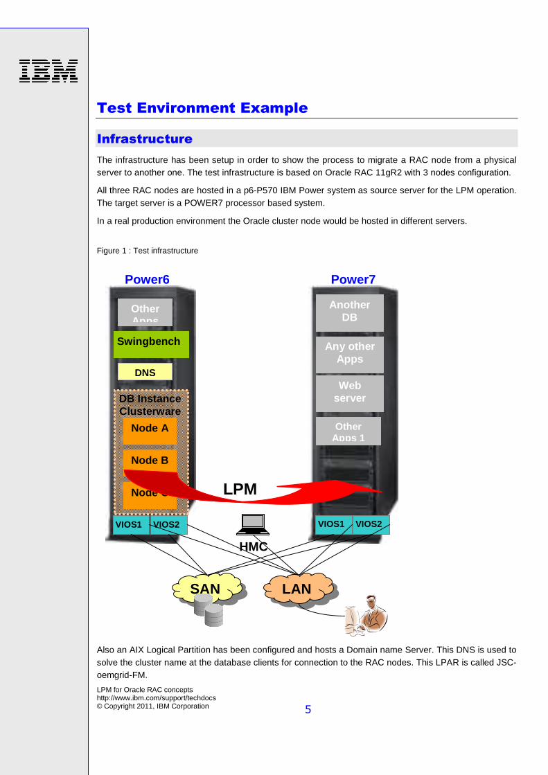
The infrastructure has been setup in order to show the process to migrate a RAC node from a physical server to another one. The test infrastructure is based on Oracle RAC 11gR2 with 3 nodes configuration.
All three RAC nodes are hosted in a p6-P570 IBM Power system as source server for the LPM operation. The target server is a POWER7 processor based system.
In a real production environment the Oracle cluster node would be hosted in different servers.
Figure 1 : Test infrastructure
Also an AIX Logical Partition has been configured and hosts a Domain name Server. This DNS is used to solve the cluster name at the database clients for connection to the RAC nodes. This LPAR is called JSC-oemgrid-FM.
VIOS1 VIOS2 VIOS1 S1
VIOS2 S2
LAN SAN
Power6
Node C
Other Apps
Another DB
Node B
Node A
Swingbench
Power7
DNS
Any other Apps
Web server
HMC
LPM
Other Apps 1
DB Instance Clusterware
LPM for Oracle RAC concepts http://www.ibm.com/support/techdocs © Copyright 2011, IBM Corporation
6
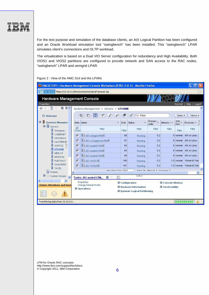
For the test purpose and simulation of the database clients, an AIX Logical Partition has been configured and an Oracle Workload simulation tool “swingbench” has been installed. This “swingbench” LPAR simulates client’s connections and OLTP workload.
The virtualization is based on a Dual VIO Server configuration for redundancy and High Availability. Both VIOS1 and VIOS2 partitions are configured to provide network and SAN access to the RAC nodes, “swingbench” LPAR and oemgrid LPAR.
Figure 2 : View of the HMC GUI and the LPARs
LPM for Oracle RAC concepts http://www.ibm.com/support/techdocs © Copyright 2011, IBM Corporation
7
The following table lists the details of the LPARs on the source server.
LPAR CPU Memory OS
JSC-node42-FM JSC-node43-FM JSC-node44-FM
Shared CPU, uncapped, Weight=128, CE=0.2, 2 Virtual Processors
6 GB AIX 6.1 TL05 SP1
JSC-VIOS1-FM JSC-VIOS2-FM
Shared CPU, uncapped, Weight=128, CE=0.2, 2 Virtual Processors
1.5 GB VIOS 2.1.3.10 FP23
The following table lists the details of the LPARs on the target server.
LPAR CPU Memory OS
JSC-VIOS3-FM JSC-VIOS4-FM
Shared CPU, uncapped, Weight=128, CE=0.2, 2 Virtual Processors
1.5 GB VIOS 2.1.3.10 FP23
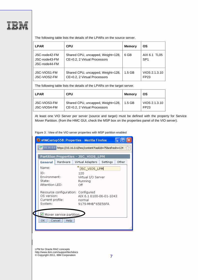
At least one VIO Server per server (source and target) must be defined with the property for Service Mover Partition. (from the HMC GUI, check the MSP box on the properties panel of the VIO server).
Figure 3 : View of the VIO server properties with MSP partition enabled
LPM for Oracle RAC concepts http://www.ibm.com/support/techdocs © Copyright 2011, IBM Corporation
8
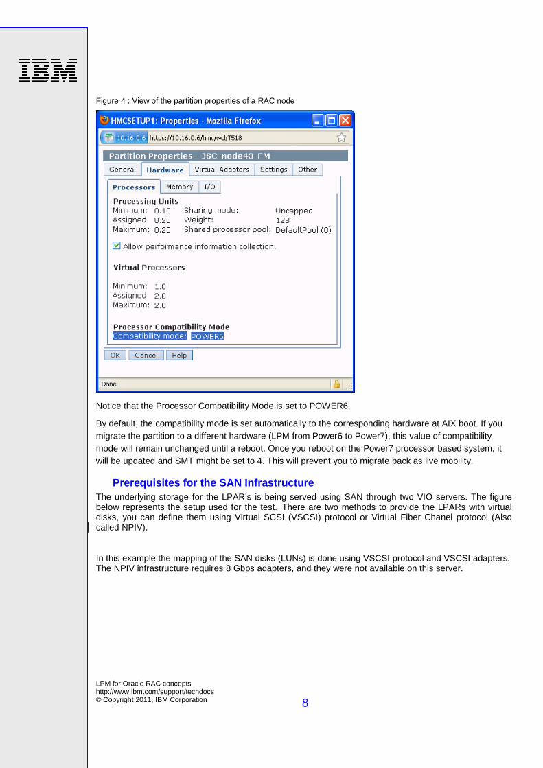
Figure 4 : View of the partition properties of a RAC node
Notice that the Processor Compatibility Mode is set to POWER6.
By default, the compatibility mode is set automatically to the corresponding hardware at AIX boot. If you migrate the partition to a different hardware (LPM from Power6 to Power7), this value of compatibility mode will remain unchanged until a reboot. Once you reboot on the Power7 processor based system, it will be updated and SMT might be set to 4. This will prevent you to migrate back as live mobility.
Prerequisites for the SAN Infrastructure The underlying storage for the LPAR’s is being served using SAN through two VIO servers. The figure below represents the setup used for the test. There are two methods to provide the LPARs with virtual disks, you can define them using Virtual SCSI (VSCSI) protocol or Virtual Fiber Chanel protocol (Also called NPIV). In this example the mapping of the SAN disks (LUNs) is done using VSCSI protocol and VSCSI adapters. The NPIV infrastructure requires 8 Gbps adapters, and they were not available on this server.
LPM for Oracle RAC concepts http://www.ibm.com/support/techdocs © Copyright 2011, IBM Corporation
9
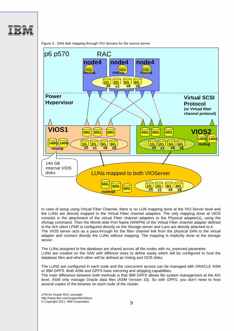
Figure 5 : SAN disk mapping through VIO Servers for the source server
In case of setup using Virtual Fiber Channel, there is no LUN mapping done at the VIO Server level and the LUNs are directly mapped to the Virtual Fiber channel adapters. The only mapping done at VIOS consists in the attachment of the virtual Fiber channel adapters to the Physical adapter(s), using the vfcmap command. Then the World wide Port Name (WWPN) of the Virtual Fiber channel adapter defined in the AIX client LPAR is configured directly on the Storage server and Luns are directly attached to it. The VIOS server acts as a pass-through for the fiber channel link from the physical SAN to the virtual adapter and connect directly the LUNs without mapping. The mapping is implicitly done at the storage server. The LUNs assigned to the database are shared across all the nodes with no_reserved parameter. LUNs are created on the SAN with different sizes to define easily which will be configured to host the database files and which other will be defined as Voting and OCR disks. The LUNS are configured in each node and the concurrent access can be managed with ORACLE ASM or IBM GPFS. Both ASM and GPFS have mirroring and stripping capabilities. The main difference between both methods is that IBM GPFS allows file system management at the AIX level, ASM only manage Oracle data files (ASM Version 10). So with GPFS, you don’t need to host several copies of the binaries on each node of the cluster.
node4 node4 node4
VIOS1 VIOS2
RAC
50G
1G 2G 5G 6G x5 x1 x6 x6
1G 2G 5G 6G x5 x1 x6 x6
50G
1G 2G 5G 6G x5 x1 x6 x6
1G 2G 5G 6G x5 x1 x6 x6
140G 140G
Power Hypervisor
p6 p570
LUNs mapped to both VIOServer
Virtual SCSI Protocol (or Virtual fiber channel protocol)
50G 50G
rootvg 50G
rootvg 50G
rootvg
rootvg
rootvgs
140G 140G rootvg
50G 50G 50G 50G 50G 50G
140 GB
internal VIOS disks
LPM for Oracle RAC concepts http://www.ibm.com/support/techdocs © Copyright 2011, IBM Corporation
10
In this example we have decided to implement ASM for sharing the SAN disks across the nodes of the cluster. We defined 6 GB size LUNS for ASM. Instead of ASM we could have use GPFS to share the SAN disks in a similar way.
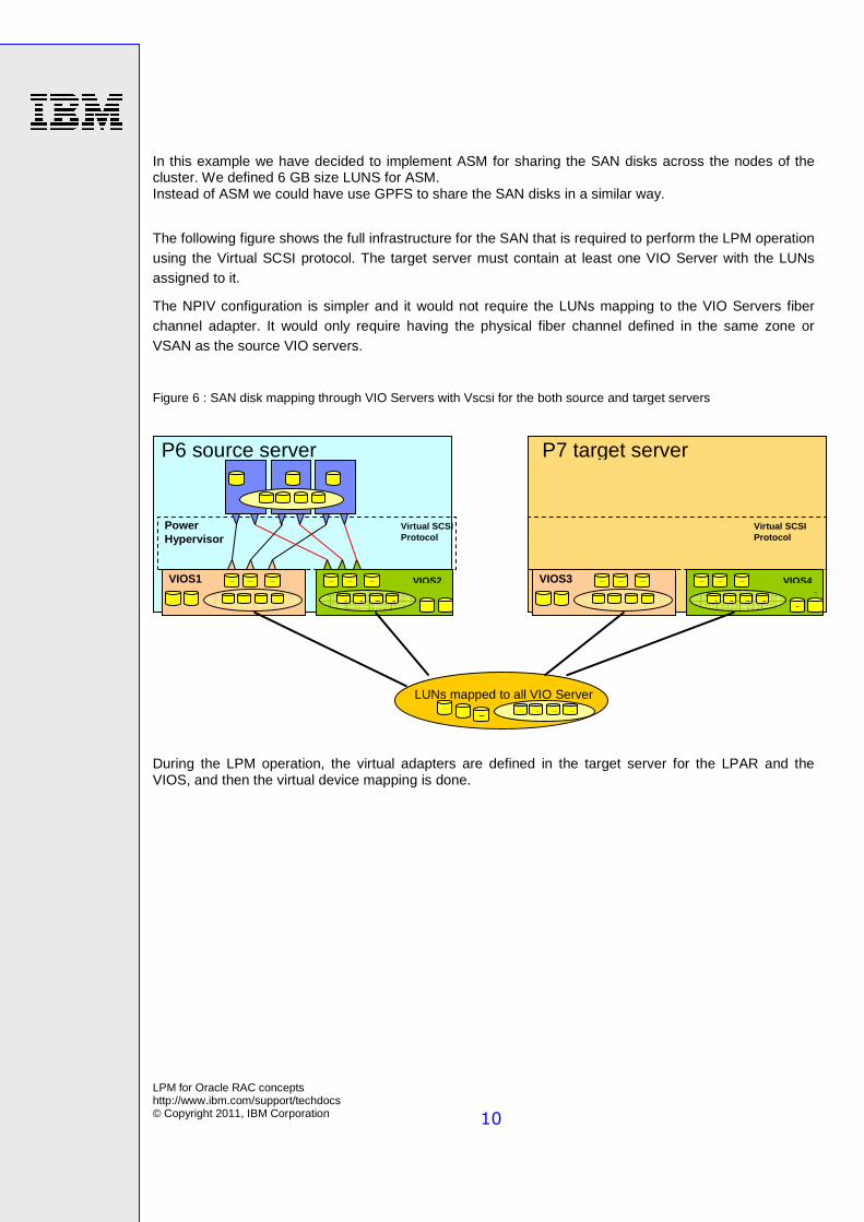
The following figure shows the full infrastructure for the SAN that is required to perform the LPM operation using the Virtual SCSI protocol. The target server must contain at least one VIO Server with the LUNs assigned to it.
The NPIV configuration is simpler and it would not require the LUNs mapping to the VIO Servers fiber channel adapter. It would only require having the physical fiber channel defined in the same zone or VSAN as the source VIO servers.
Figure 6 : SAN disk mapping through VIO Servers with Vscsi for the both source and target servers
During the LPM operation, the virtual adapters are defined in the target server for the LPAR and the VIOS, and then the virtual device mapping is done.
RAC
1 2 5 6x x x x5 5 5roo
no no no
VIOS1 VIOS2
5
1 2 5 6x x x x
1 2 5 6x x x x 1 2 5 6x x x x1 1
Power Hypervisor
LUNs mapped to all VIO Server Fibers
Virtual SCSI Protocol
ro 5roo 5ro
ro 1 1roo
5 5 5 5 5 5VIOS3 VIOS4
1 2 5 6x x x x 1 2 5 6x x x x1 1ro 1
1roo
5 5 5 5 5 5
P7 target server P6 source server
Virtual SCSI Protocol
LPM for Oracle RAC concepts http://www.ibm.com/support/techdocs © Copyright 2011, IBM Corporation
11
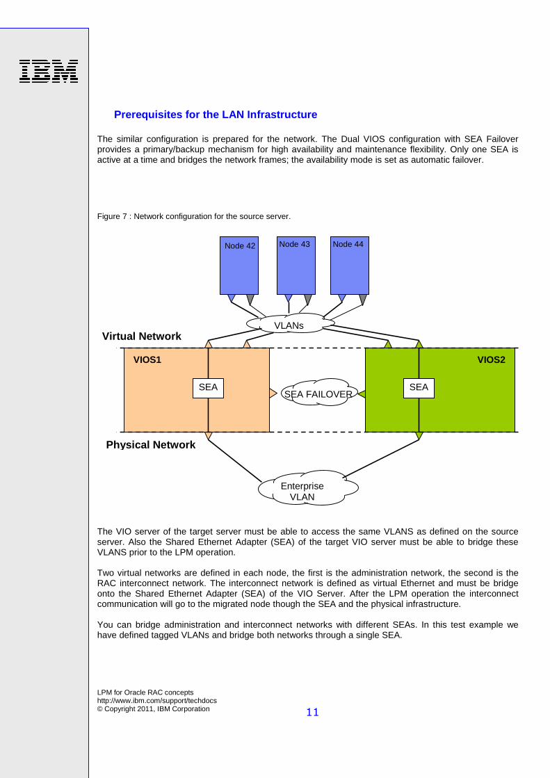
Prerequisites for the LAN Infrastructure The similar configuration is prepared for the network. The Dual VIOS configuration with SEA Failover provides a primary/backup mechanism for high availability and maintenance flexibility. Only one SEA is active at a time and bridges the network frames; the availability mode is set as automatic failover.
Figure 7 : Network configuration for the source server.
The VIO server of the target server must be able to access the same VLANS as defined on the source server. Also the Shared Ethernet Adapter (SEA) of the target VIO server must be able to bridge these VLANS prior to the LPM operation. Two virtual networks are defined in each node, the first is the administration network, the second is the RAC interconnect network. The interconnect network is defined as virtual Ethernet and must be bridge onto the Shared Ethernet Adapter (SEA) of the VIO Server. After the LPM operation the interconnect communication will go to the migrated node though the SEA and the physical infrastructure. You can bridge administration and interconnect networks with different SEAs. In this test example we have defined tagged VLANs and bridge both networks through a single SEA.
Node 42
VIOS1 VIOS2
Node 43 Node 44
SEA SEA
VLANs
SEA FAILOVER
Enterprise VLAN
Physical Ne twork
Virtual Network
LPM for Oracle RAC concepts http://www.ibm.com/support/techdocs © Copyright 2011, IBM Corporation
12
Enterprise VLAN
Node 42
VIOS1 VIOS2
Node 43 Node 44
SEA SEA
VLANs
SEA FAILOVER
Physical Network
Virtual Network VIOS2
SEA SEA
VLANs
SEA FAILOVER
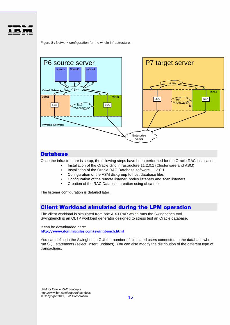
Figure 8 : Network configuration for the whole infrastructure.
Database
Once the infrastructure is setup, the following steps have been performed for the Oracle RAC installation: • Installation of the Oracle Grid infrastructure 11.2.0.1 (Clusterware and ASM) • Installation of the Oracle RAC Database software 11.2.0.1 • Configuration of the ASM diskgroup to host database files • Configuration of the remote listener, nodes listeners and scan listeners • Creation of the RAC Database creation using dbca tool
The listener configuration is detailed later.
Client Workload simulated during the LPM operation
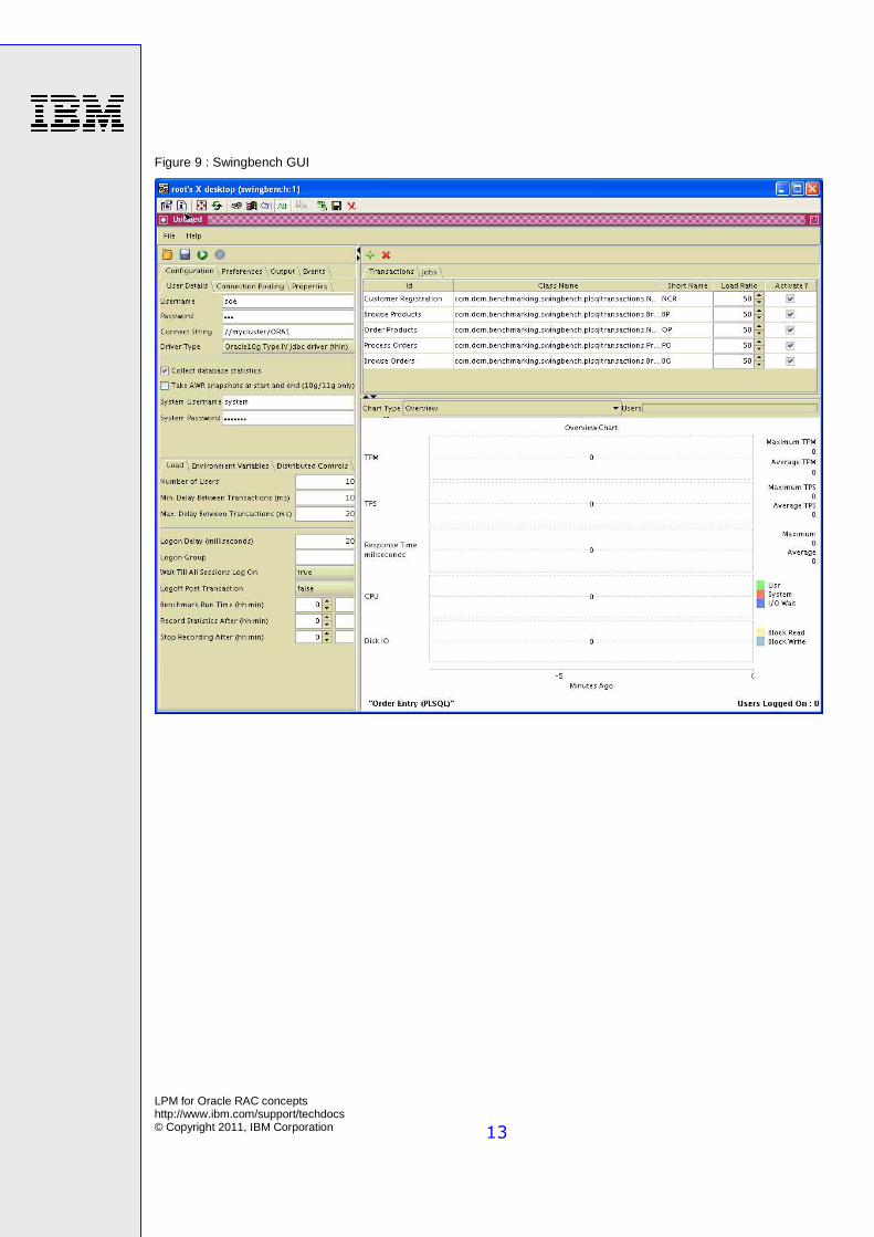
The client workload is simulated from one AIX LPAR which runs the Swingbench tool. Swingbench is an OLTP workload generator designed to stress test an Oracle database. It can be downloaded here: http://www.dominicgiles.com/swingbench.html You can define in the Swingbench GUI the number of simulated users connected to the database who run SQL statements (select, insert, updates). You can also modify the distribution of the different type of transactions.
P7 target server P6 source server
LPM for Oracle RAC concepts http://www.ibm.com/support/techdocs © Copyright 2011, IBM Corporation
13
Figure 9 : Swingbench GUI
LPM for Oracle RAC concepts http://www.ibm.com/support/techdocs © Copyright 2011, IBM Corporation
14
Unsupported LPM operation for Oracle RAC for
testing
At the time of writing LPM operation on an Oracle RAC node is not supported with Database and Clusterware started.
At the end of the LPM process, during the memory block migration to the target server, a short freeze of the processes may happen depending on the memory activity. The Oracle cluster mechanism permanently checks the nodes connectivity and the internal monitoring processes are defined with timeout delays. Then, the LPM operation may generate a delay and Oracle RAC monitoring may be disturbed. In the worst case of disruption during the migration, the node will get out of the cluster and will reboot. This is regular behavior of the Oracle RAC cluster.
In any case the client connections to the database node which is LPM migrated may be also disrupted depending on the application code. The application server may manage the client connection to be restarted on another node of the cluster.
You can use this process for test and development purpose, not for production environment. In this case you can test a migration of one RAC node without stopping the cluster on it. The workload will run on the remaining node(s) and client connections to the node may be stopped depending on the connection configuration.
We performed the LPM on a live Oracle RAC node running the Swingbench workload as an example for test environment. The following figures show the Live Partition Mobility progress.
Figure 10 : Screen shots of the Hardware Management Console (HMC)
LPM for Oracle RAC concepts http://www.ibm.com/support/techdocs © Copyright 2011, IBM Corporation
15
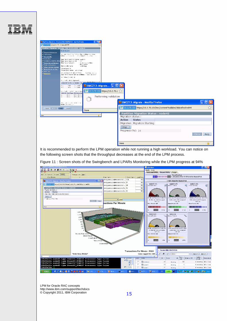
It is recommended to perform the LPM operation while not running a high workload. You can notice on the following screen shots that the throughput decreases at the end of the LPM process.
Figure 11 : Screen shots of the Swingbench and LPARs Monitoring while the LPM progress at 94%
LPM for Oracle RAC concepts http://www.ibm.com/support/techdocs © Copyright 2011, IBM Corporation
16
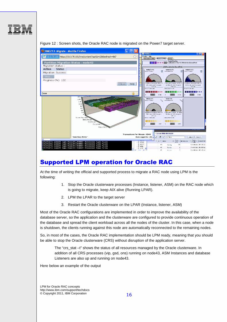
Figure 12 : Screen shots, the Oracle RAC node is migrated on the Power7 target server.
Supported LPM operation for Oracle RAC
At the time of writing the official and supported process to migrate a RAC node using LPM is the following:
1. Stop the Oracle clusterware processes (Instance, listener, ASM) on the RAC node which is going to migrate, keep AIX alive (Running LPAR).
2. LPM the LPAR to the target server
3. Restart the Oracle clusterware on the LPAR (Instance, listener, ASM)
Most of the Oracle RAC configurations are implemented in order to improve the availability of the database server, so the application and the clusterware are configured to provide continuous operation of the database and spread the client workload across all the nodes of the cluster. In this case, when a node is shutdown, the clients running against this node are automatically reconnected to the remaining nodes.
So, in most of the cases, the Oracle RAC implementation should be LPM ready, meaning that you should be able to stop the Oracle clusterware (CRS) without disruption of the application server.
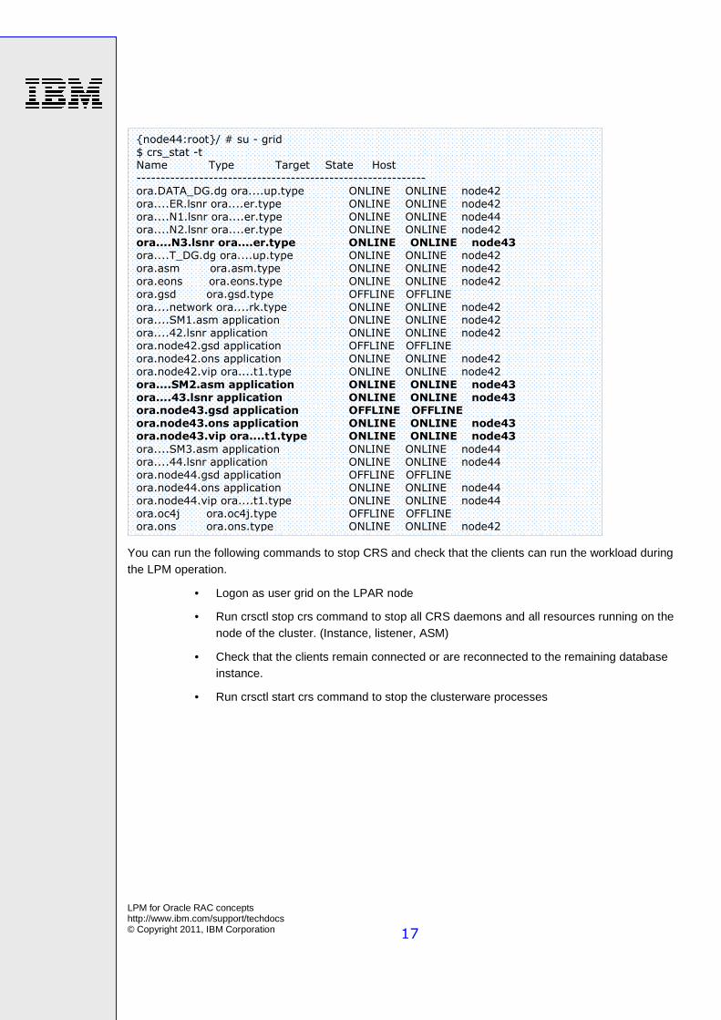
The “crs_stat –t” shows the status of all resources managed by the Oracle clusterware. In addition of all CRS processes (vip, gsd, ons) running on node43, ASM Instances and database Listeners are also up and running on node43.
Here below an example of the output
LPM for Oracle RAC concepts http://www.ibm.com/support/techdocs © Copyright 2011, IBM Corporation
17
You can run the following commands to stop CRS and check that the clients can run the workload during the LPM operation.
• Logon as user grid on the LPAR node
• Run crsctl stop crs command to stop all CRS daemons and all resources running on the node of the cluster. (Instance, listener, ASM)
• Check that the clients remain connected or are reconnected to the remaining database instance.
• Run crsctl start crs command to stop the clusterware processes
{node44:root}/ # su - grid
$ crs_stat -t Name Type Target State Host
------------------------------------------------------------
ora.DATA_DG.dg ora....up.type ONLINE ONLINE node42
ora....ER.lsnr ora....er.type ONLINE ONLINE node42
ora....N1.lsnr ora....er.type ONLINE ONLINE node44 ora....N2.lsnr ora....er.type ONLINE ONLINE node42
ora....N3.lsnr ora....er.type ONLINE ONLINE node43 ora....T_DG.dg ora....up.type ONLINE ONLINE node42
ora.asm ora.asm.type ONLINE ONLINE node42
ora.eons ora.eons.type ONLINE ONLINE node42
ora.gsd ora.gsd.type OFFLINE OFFLINE
ora....network ora....rk.type ONLINE ONLINE node42 ora....SM1.asm application ONLINE ONLINE node42
ora....42.lsnr application ONLINE ONLINE node42 ora.node42.gsd application OFFLINE OFFLINE
ora.node42.ons application ONLINE ONLINE node42
ora.node42.vip ora....t1.type ONLINE ONLINE node42
ora....SM2.asm application ONLINE ONLINE node43
ora....43.lsnr application ONLINE ONLINE node43 ora.node43.gsd application OFFLINE OFFLINE
ora.node43.ons application ONLINE ONLINE node43 ora.node43.vip ora....t1.type ONLINE ONLINE node43
ora....SM3.asm application ONLINE ONLINE node44 ora....44.lsnr application ONLINE ONLINE node44
ora.node44.gsd application OFFLINE OFFLINE ora.node44.ons application ONLINE ONLINE node44
ora.node44.vip ora....t1.type ONLINE ONLINE node44
ora.oc4j ora.oc4j.type OFFLINE OFFLINE ora.ons ora.ons.type ONLINE ONLINE node42
LPM for Oracle RAC concepts http://www.ibm.com/support/techdocs © Copyright 2011, IBM Corporation
18
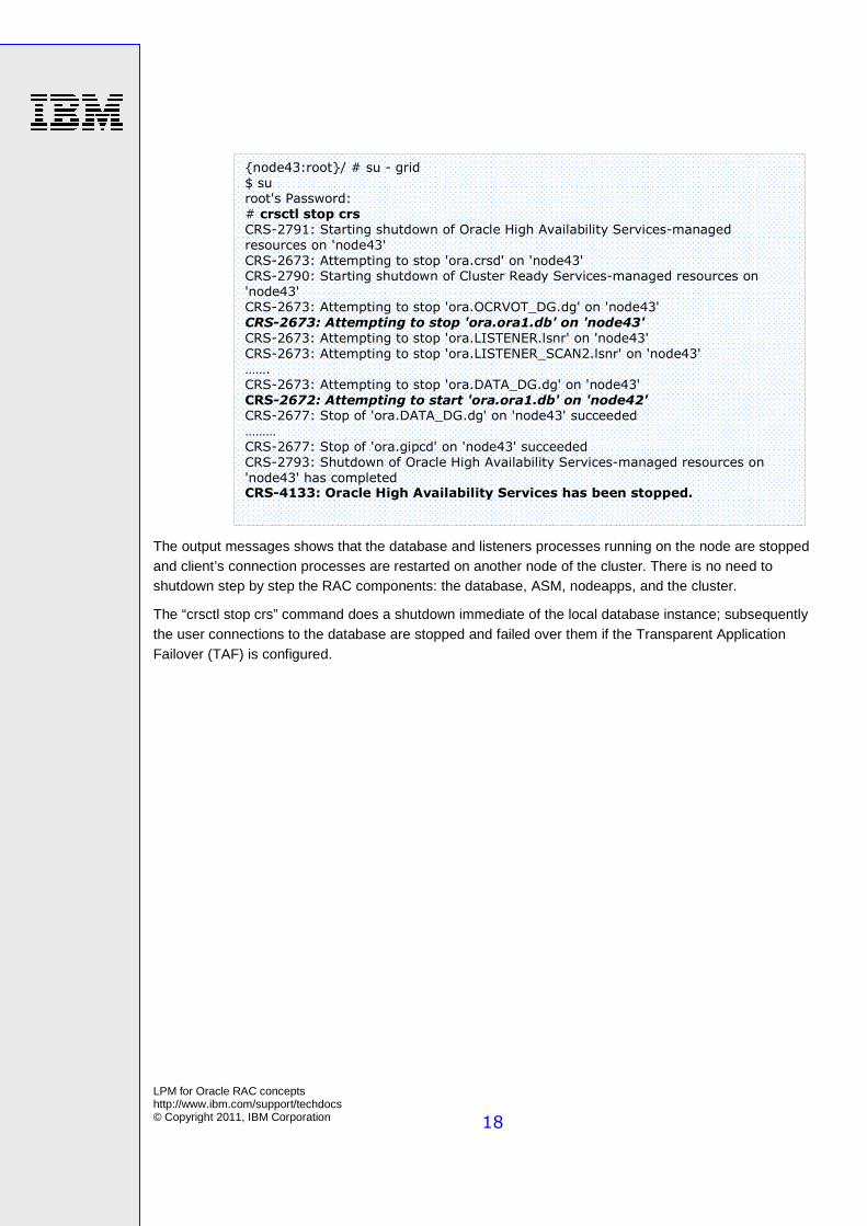
The output messages shows that the database and listeners processes running on the node are stopped and client’s connection processes are restarted on another node of the cluster. There is no need to shutdown step by step the RAC components: the database, ASM, nodeapps, and the cluster.
The “crsctl stop crs” command does a shutdown immediate of the local database instance; subsequently the user connections to the database are stopped and failed over them if the Transparent Application Failover (TAF) is configured.
{node43:root}/ # su - grid
$ su root's Password:
# crsctl stop crs
CRS-2791: Starting shutdown of Oracle High Availability Services-managed
resources on 'node43'
CRS-2673: Attempting to stop 'ora.crsd' on 'node43' CRS-2790: Starting shutdown of Cluster Ready Services-managed resources on
'node43' CRS-2673: Attempting to stop 'ora.OCRVOT_DG.dg' on 'node43'
CRS-2673: Attempting to stop 'ora.ora1.db' on 'node43'
CRS-2673: Attempting to stop 'ora.LISTENER.lsnr' on 'node43'
CRS-2673: Attempting to stop 'ora.LISTENER_SCAN2.lsnr' on 'node43'
……. CRS-2673: Attempting to stop 'ora.DATA_DG.dg' on 'node43'
CRS-2672: Attempting to start 'ora.ora1.db' on 'node42' CRS-2677: Stop of 'ora.DATA_DG.dg' on 'node43' succeeded
………
CRS-2677: Stop of 'ora.gipcd' on 'node43' succeeded
CRS-2793: Shutdown of Oracle High Availability Services-managed resources on
'node43' has completed CRS-4133: Oracle High Availability Services has been stopped.
LPM for Oracle RAC concepts http://www.ibm.com/support/techdocs © Copyright 2011, IBM Corporation
19
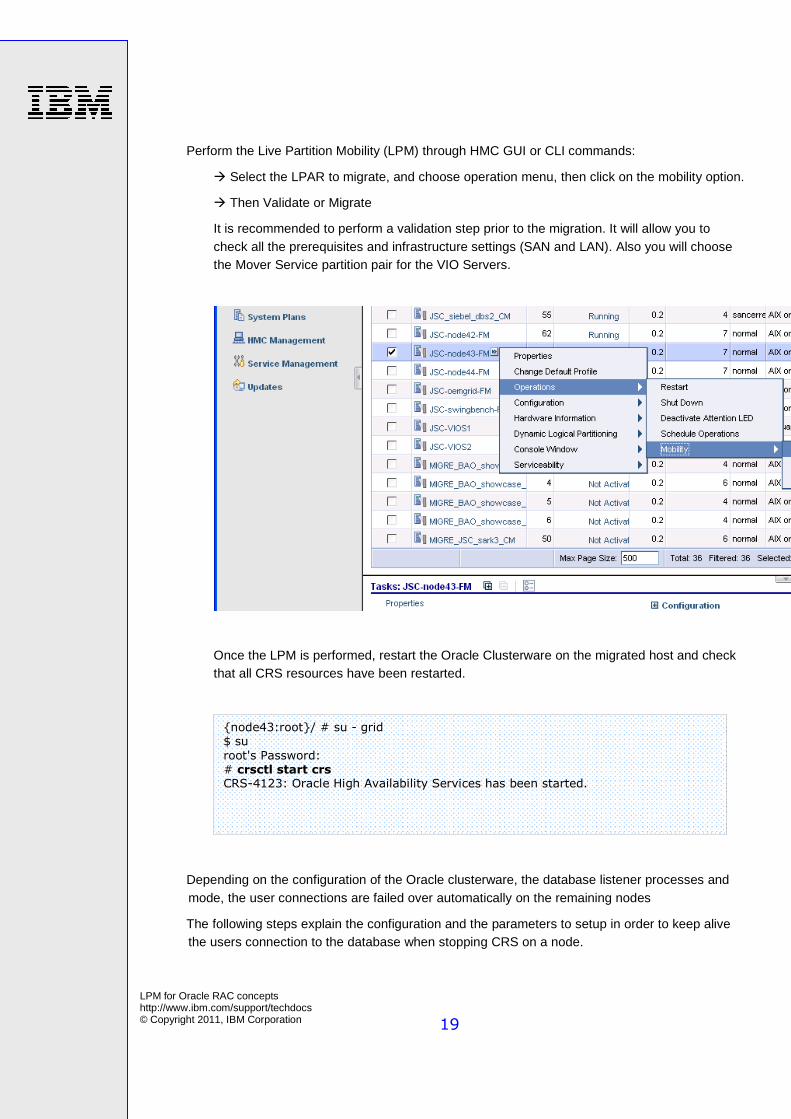
Perform the Live Partition Mobility (LPM) through HMC GUI or CLI commands:
� Select the LPAR to migrate, and choose operation menu, then click on the mobility option.
� Then Validate or Migrate
It is recommended to perform a validation step prior to the migration. It will allow you to check all the prerequisites and infrastructure settings (SAN and LAN). Also you will choose the Mover Service partition pair for the VIO Servers.
Once the LPM is performed, restart the Oracle Clusterware on the migrated host and check that all CRS resources have been restarted.
Depending on the configuration of the Oracle clusterware, the database listener processes and mode, the user connections are failed over automatically on the remaining nodes
The following steps explain the configuration and the parameters to setup in order to keep alive the users connection to the database when stopping CRS on a node.
{node43:root}/ # su - grid $ su
root's Password: # crsctl start crs CRS-4123: Oracle High Availability Services has been started.
LPM for Oracle RAC concepts http://www.ibm.com/support/techdocs © Copyright 2011, IBM Corporation
20
Client configuration of the Transparent Application Failover
(TAF) for continuous operation
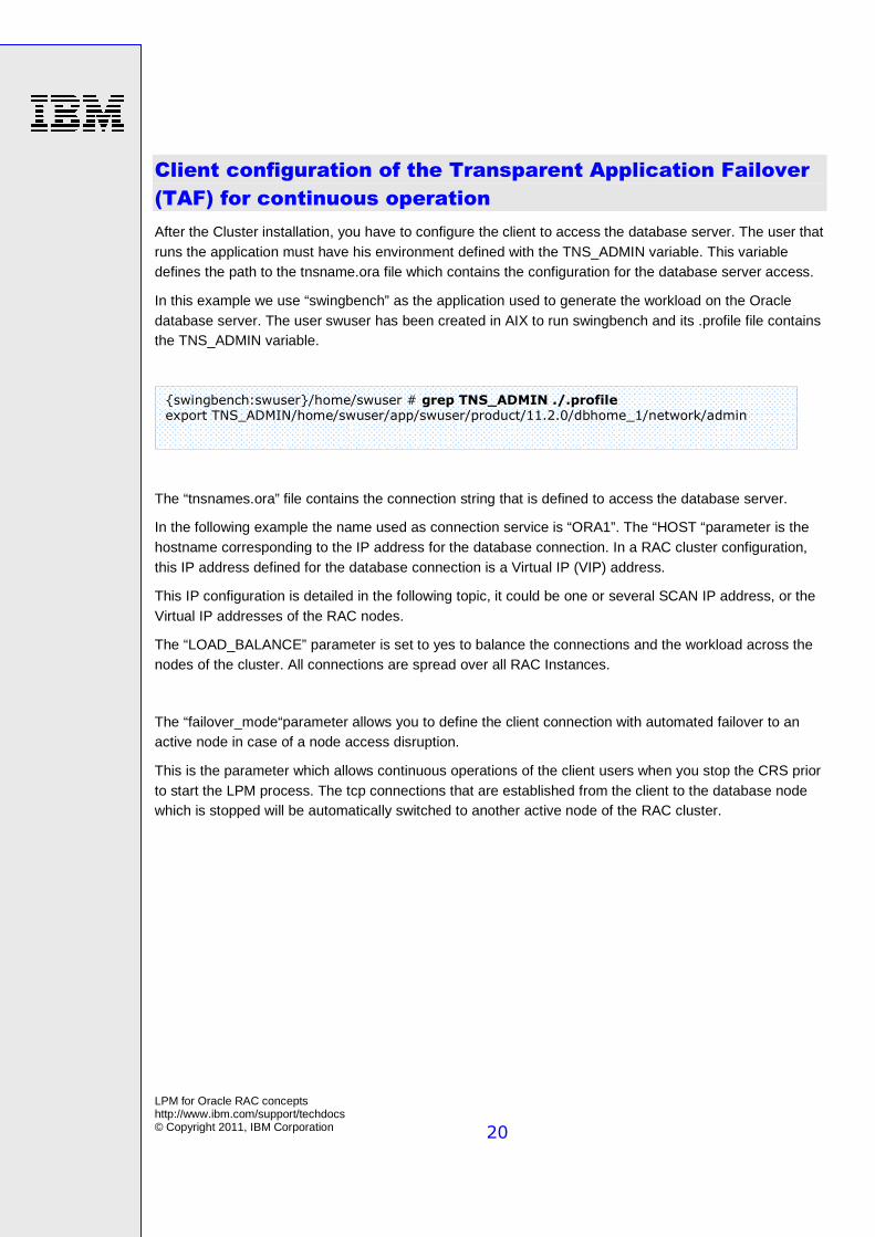
After the Cluster installation, you have to configure the client to access the database server. The user that runs the application must have his environment defined with the TNS_ADMIN variable. This variable defines the path to the tnsname.ora file which contains the configuration for the database server access.
In this example we use “swingbench” as the application used to generate the workload on the Oracle database server. The user swuser has been created in AIX to run swingbench and its .profile file contains the TNS_ADMIN variable.
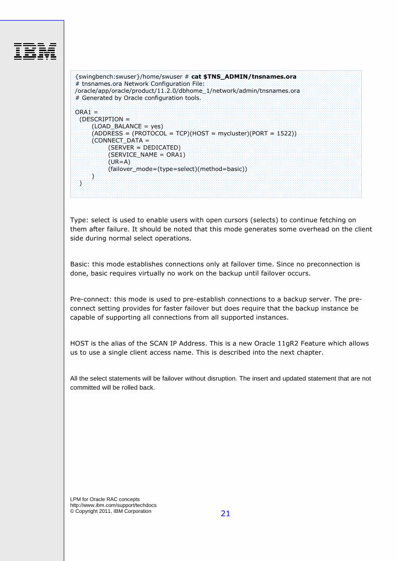
The “tnsnames.ora” file contains the connection string that is defined to access the database server.
In the following example the name used as connection service is “ORA1”. The “HOST “parameter is the hostname corresponding to the IP address for the database connection. In a RAC cluster configuration, this IP address defined for the database connection is a Virtual IP (VIP) address.
This IP configuration is detailed in the following topic, it could be one or several SCAN IP address, or the Virtual IP addresses of the RAC nodes.
The “LOAD_BALANCE” parameter is set to yes to balance the connections and the workload across the nodes of the cluster. All connections are spread over all RAC Instances.
The “failover_mode“parameter allows you to define the client connection with automated failover to an active node in case of a node access disruption.
This is the parameter which allows continuous operations of the client users when you stop the CRS prior to start the LPM process. The tcp connections that are established from the client to the database node which is stopped will be automatically switched to another active node of the RAC cluster.
{swingbench:swuser}/home/swuser # grep TNS_ADMIN ./.profile export TNS_ADMIN/home/swuser/app/swuser/product/11.2.0/dbhome_1/network/admin
LPM for Oracle RAC concepts http://www.ibm.com/support/techdocs © Copyright 2011, IBM Corporation
21
Type: select is used to enable users with open cursors (selects) to continue fetching on
them after failure. It should be noted that this mode generates some overhead on the client
side during normal select operations.
Basic: this mode establishes connections only at failover time. Since no preconnection is
done, basic requires virtually no work on the backup until failover occurs.
Pre-connect: this mode is used to pre-establish connections to a backup server. The pre-
connect setting provides for faster failover but does require that the backup instance be
capable of supporting all connections from all supported instances.
HOST is the alias of the SCAN IP Address. This is a new Oracle 11gR2 Feature which allows
us to use a single client access name. This is described into the next chapter.
All the select statements will be failover without disruption. The insert and updated statement that are not committed will be rolled back.
{swingbench:swuser}/home/swuser # cat $TNS_ADMIN/tnsnames.ora
# tnsnames.ora Network Configuration File: /oracle/app/oracle/product/11.2.0/dbhome_1/network/admin/tnsnames.ora
# Generated by Oracle configuration tools.
ORA1 =
(DESCRIPTION = (LOAD_BALANCE = yes)
(ADDRESS = (PROTOCOL = TCP)(HOST = mycluster)(PORT = 1522)) (CONNECT_DATA =
(SERVER = DEDICATED)
(SERVICE_NAME = ORA1)
(UR=A)
(failover_mode=(type=select)(method=basic)) ) )
LPM for Oracle RAC concepts http://www.ibm.com/support/techdocs © Copyright 2011, IBM Corporation
22
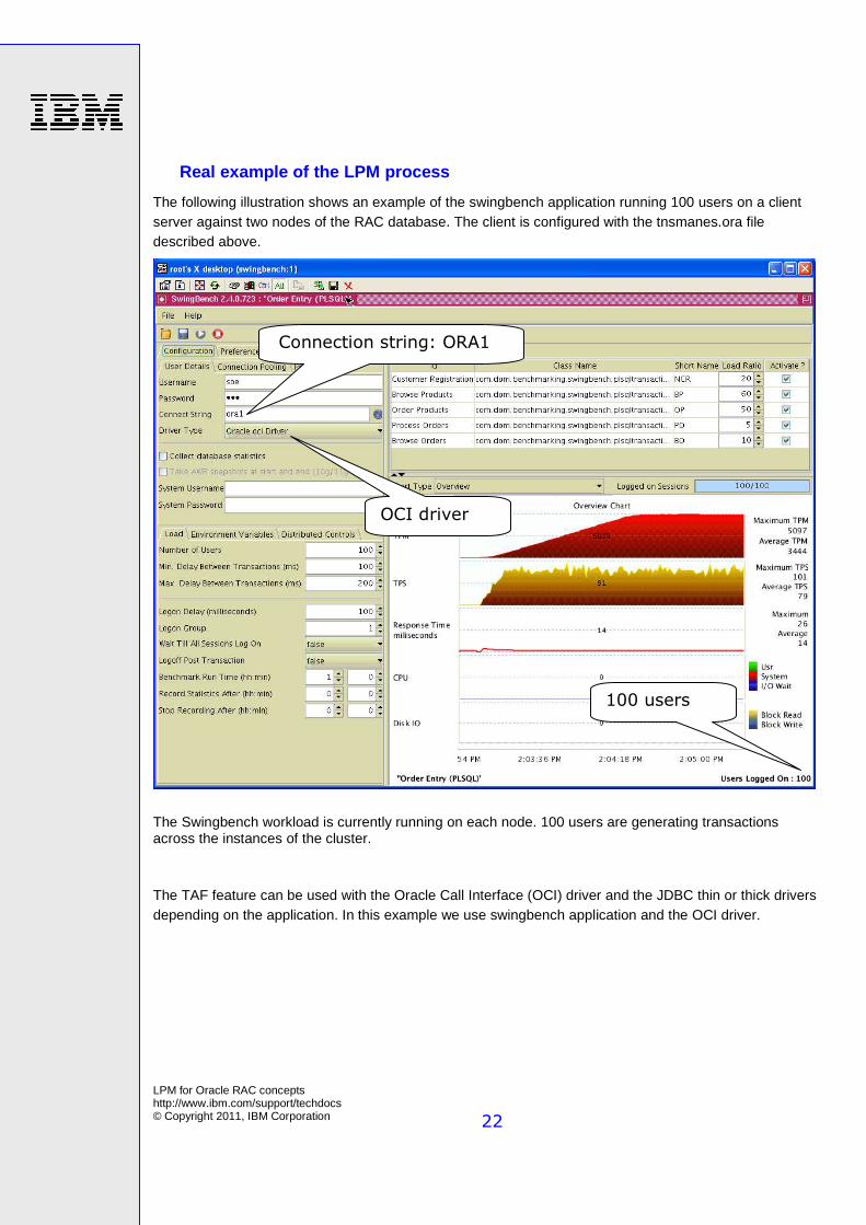
Real example of the LPM process
The following illustration shows an example of the swingbench application running 100 users on a client server against two nodes of the RAC database. The client is configured with the tnsmanes.ora file described above.
The Swingbench workload is currently running on each node. 100 users are generating transactions across the instances of the cluster.
The TAF feature can be used with the Oracle Call Interface (OCI) driver and the JDBC thin or thick drivers depending on the application. In this example we use swingbench application and the OCI driver.
100 users
Connection string: ORA1
OCI driver
LPM for Oracle RAC concepts http://www.ibm.com/support/techdocs © Copyright 2011, IBM Corporation
23
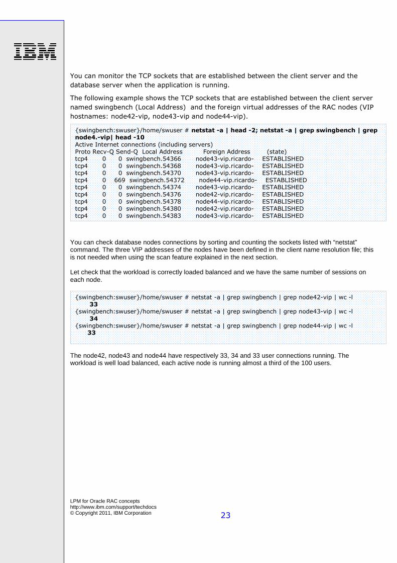
You can monitor the TCP sockets that are established between the client server and the
database server when the application is running.
The following example shows the TCP sockets that are established between the client server
named swingbench (Local Address) and the foreign virtual addresses of the RAC nodes (VIP
hostnames: node42-vip, node43-vip and node44-vip).
You can check database nodes connections by sorting and counting the sockets listed with “netstat” command. The three VIP addresses of the nodes have been defined in the client name resolution file; this is not needed when using the scan feature explained in the next section. Let check that the workload is correctly loaded balanced and we have the same number of sessions on each node.
The node42, node43 and node44 have respectively 33, 34 and 33 user connections running. The workload is well load balanced, each active node is running almost a third of the 100 users.
{swingbench:swuser}/home/swuser # netstat -a | grep swingbench | grep node42-vip | wc -l
33 {swingbench:swuser}/home/swuser # netstat -a | grep swingbench | grep node43-vip | wc -l
34 {swingbench:swuser}/home/swuser # netstat -a | grep swingbench | grep node44-vip | wc -l 33
{swingbench:swuser}/home/swuser # netstat -a | head -2; netstat -a | grep swingbench | grep node4.-vip| head -10
Active Internet connections (including servers)
Proto Recv-Q Send-Q Local Address Foreign Address (state) tcp4 0 0 swingbench.54366 node43-vip.ricardo- ESTABLISHED
tcp4 0 0 swingbench.54368 node43-vip.ricardo- ESTABLISHED tcp4 0 0 swingbench.54370 node43-vip.ricardo- ESTABLISHED
tcp4 0 669 swingbench.54372 node44-vip.ricardo- ESTABLISHED tcp4 0 0 swingbench.54374 node43-vip.ricardo- ESTABLISHED
tcp4 0 0 swingbench.54376 node42-vip.ricardo- ESTABLISHED
tcp4 0 0 swingbench.54378 node44-vip.ricardo- ESTABLISHED tcp4 0 0 swingbench.54380 node42-vip.ricardo- ESTABLISHED
tcp4 0 0 swingbench.54383 node43-vip.ricardo- ESTABLISHED
LPM for Oracle RAC concepts http://www.ibm.com/support/techdocs © Copyright 2011, IBM Corporation
24
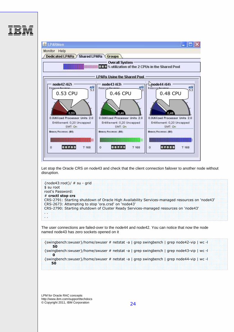
Let stop the Oracle CRS on node43 and check that the client connection failover to another node without disruption.
The user connections are failed-over to the node44 and node42. You can notice that now the node named node43 has zero sockets opened on it
{swingbench:swuser}/home/swuser # netstat -a | grep swingbench | grep node42-vip | wc -l
50
{swingbench:swuser}/home/swuser # netstat -a | grep swingbench | grep node43-vip | wc -l
0 {swingbench:swuser}/home/swuser # netstat -a | grep swingbench | grep node44-vip | wc -l 50
{node43:root}/ # su - grid
$ su root
root's Password:
# crsctl stop crs
CRS-2791: Starting shutdown of Oracle High Availability Services-managed resources on 'node43' CRS-2673: Attempting to stop 'ora.crsd' on 'node43'
CRS-2790: Starting shutdown of Cluster Ready Services-managed resources on 'node43' . . . .
0.53 CPU 0.48 CPU 0.46 CPU
LPM for Oracle RAC concepts http://www.ibm.com/support/techdocs © Copyright 2011, IBM Corporation
25
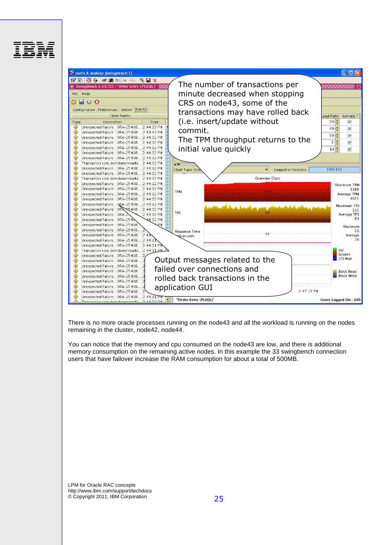
There is no more oracle processes running on the node43 and all the workload is running on the nodes remaining in the cluster, node42, node44. You can notice that the memory and cpu consumed on the node43 are low, and there is additional memory consumption on the remaining active nodes. In this example the 33 swingbench connection users that have failover increase the RAM consumption for about a total of 500MB.
The number of transactions per minute decreased when stopping
CRS on node43, some of the transactions may have rolled back (i.e. insert/update without commit.
The TPM throughput returns to the initial value quickly
Output messages related to the failed over connections and rolled back transactions in the
application GUI
LPM for Oracle RAC concepts http://www.ibm.com/support/techdocs © Copyright 2011, IBM Corporation
26
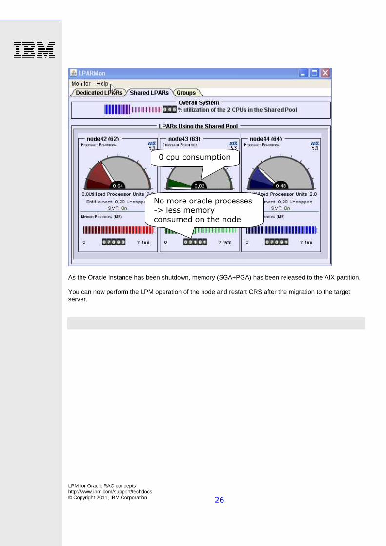
As the Oracle Instance has been shutdown, memory (SGA+PGA) has been released to the AIX partition. You can now perform the LPM operation of the node and restart CRS after the migration to the target server.
0 cpu consumption
No more oracle processes -> less memory
consumed on the node
LPM for Oracle RAC concepts http://www.ibm.com/support/techdocs © Copyright 2011, IBM Corporation
27
Server configuration of the Single Client Access Name
(SCAN) listener
During the cluster configuration, several resources are created for the database connection. Oracle RAC 11gR2 provides a feature named SCAN listener that provides single name connection to the cluster database. In this case there is no dependency between the database Client and the nodes of the cluster.
The SCAN feature is part of the Oracle grid infrastructure which makes a flexible client connection to the database and automates the workload balancing. SCAN feature is similar to an abstraction layer between the Clients and the database nodes.
The SCAN name is a hostname which is associated to several Virtual IP addresses (VIP) called SCAN VIPs. The SCAN name provides a single access name to the database. This single access name is used by the client in the connection string.
For each SCAN VIP address a SCAN listener process is started. The SCAN listeners are dispersed across the LPAR nodes of the cluster. If the node where a SCAN VIP is running fails, the SCAN VIP and its associated listener will failover to another node in the cluster.
The SCAN name can be resolved locally or from a DNS. If you use the SCAN feature you don’t need to define in the client the name resolution of the VIP addresses of the nodes.
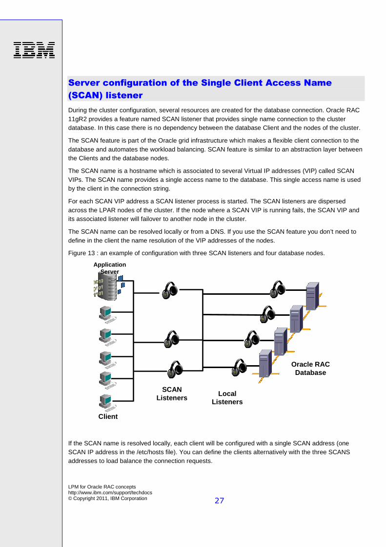
Figure 13 : an example of configuration with three SCAN listeners and four database nodes.
If the SCAN name is resolved locally, each client will be configured with a single SCAN address (one SCAN IP address in the /etc/hosts file). You can define the clients alternatively with the three SCANS addresses to load balance the connection requests.
Clients
SCAN Listeners
Oracle RAC Database
Application Server
Local Listeners
LPM for Oracle RAC concepts http://www.ibm.com/support/techdocs © Copyright 2011, IBM Corporation
28
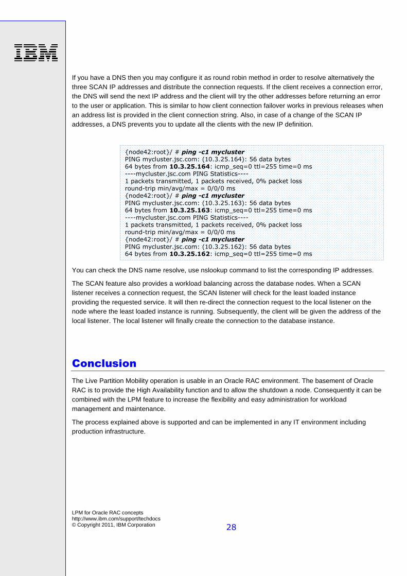
If you have a DNS then you may configure it as round robin method in order to resolve alternatively the three SCAN IP addresses and distribute the connection requests. If the client receives a connection error, the DNS will send the next IP address and the client will try the other addresses before returning an error to the user or application. This is similar to how client connection failover works in previous releases when an address list is provided in the client connection string. Also, in case of a change of the SCAN IP addresses, a DNS prevents you to update all the clients with the new IP definition.
You can check the DNS name resolve, use nslookup command to list the corresponding IP addresses.
The SCAN feature also provides a workload balancing across the database nodes. When a SCAN listener receives a connection request, the SCAN listener will check for the least loaded instance providing the requested service. It will then re-direct the connection request to the local listener on the node where the least loaded instance is running. Subsequently, the client will be given the address of the local listener. The local listener will finally create the connection to the database instance.
Conclusion
The Live Partition Mobility operation is usable in an Oracle RAC environment. The basement of Oracle RAC is to provide the High Availability function and to allow the shutdown a node. Consequently it can be combined with the LPM feature to increase the flexibility and easy administration for workload management and maintenance.
The process explained above is supported and can be implemented in any IT environment including production infrastructure.
{node42:root}/ # ping -c1 mycluster PING mycluster.jsc.com: (10.3.25.164): 56 data bytes
64 bytes from 10.3.25.164: icmp_seq=0 ttl=255 time=0 ms ----mycluster.jsc.com PING Statistics----
1 packets transmitted, 1 packets received, 0% packet loss
round-trip min/avg/max = 0/0/0 ms {node42:root}/ # ping -c1 mycluster
PING mycluster.jsc.com: (10.3.25.163): 56 data bytes 64 bytes from 10.3.25.163: icmp_seq=0 ttl=255 time=0 ms
----mycluster.jsc.com PING Statistics---- 1 packets transmitted, 1 packets received, 0% packet loss
round-trip min/avg/max = 0/0/0 ms
{node42:root}/ # ping -c1 mycluster
PING mycluster.jsc.com: (10.3.25.162): 56 data bytes 64 bytes from 10.3.25.162: icmp_seq=0 ttl=255 time=0 ms
LPM for Oracle RAC concepts http://www.ibm.com/support/techdocs © Copyright 2011, IBM Corporation
29
Resources
These Web sites provide useful references to supplement the information contained in this document:
� IBM System p Information Center http://publib.boulder.ibm.com/infocenter/pseries/index.jsp
� IBM Publications Center
www.elink.ibmlink.ibm.com/public/applications/publications/cgibin/pbi.cgi?CTY=US
� IBM Redbooks www.redbooks.ibm.com • Oracle Real Application Clusters on IBM AIX : Best Practices in Memory Tuning and Configuring
for System Stability http://www-03.ibm.com/support/techdocs/atsmastr.nsf/WebIndex/WP101513
• IBM Power Systems Live Partition Mobility (LPM) and Oracle DB Single Instance
http://www-03.ibm.com/support/techdocs/atsmastr.nsf/WebIndex/WP101566
• PowerVM Live Partition Mobility available on Oracle DB and AIX
http://www-03.ibm.com/support/techdocs/atsmastr.nsf/WebIndex/FLASH10686
About the authors Francois Martin is a technical specialist with 12 years of experience of AIX, Power Systems and Virtualization. I’ve been working for 5 years in AIX performance benchmarks, and 4 years in course delivery and development. I am now part of the IBM Oracle Center as presales support in any customer facing situation, critical situations, and competitive business, demonstrating the added value of the IBM technology compared to the competition. Frederic Dubois has worked for IBM since 2007, spending the previous year as IT Specialist. He joined the IBM Products and Solutions Support Center (PSSC) – Montpellier, France, in 2007 as member of the IBM Oracle Center (IOC), a 5 experts team based in Montpellier, cross brand, cross industries. His main activity is to define the most appropriate IBM integrated infrastructure (especially Linux cross platform) for Oracle Solutions in pre-sales stage (both including sizing, architecture design, education and benchmark support).
LPM for Oracle RAC concepts http://www.ibm.com/support/techdocs © Copyright 2011, IBM Corporation
30
Appendix : Live Partition Mobility details
Live Partition Mobility (LPM) requires a specific hardware infrastructure and configuration. This appendix is intended to focus on platform components involved in an active migration controlled by the Hardware Management Console (HMC).
Components
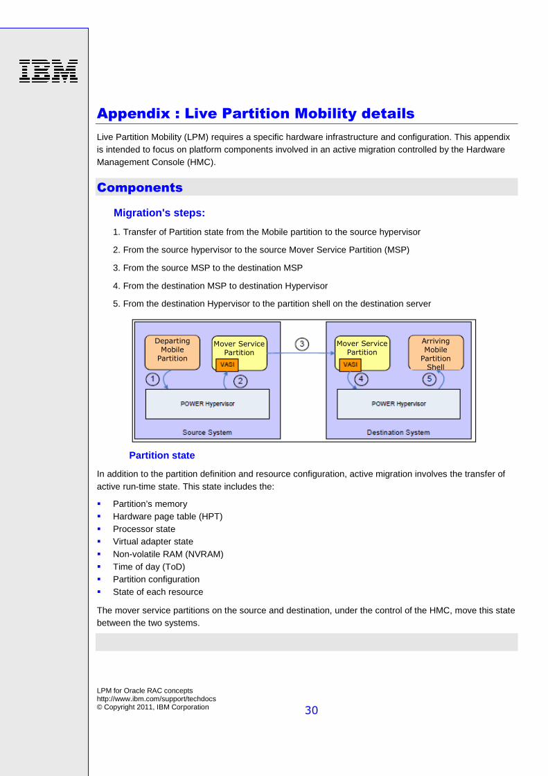
Migration's steps:
1. Transfer of Partition state from the Mobile partition to the source hypervisor
2. From the source hypervisor to the source Mover Service Partition (MSP)
3. From the source MSP to the destination MSP
4. From the destination MSP to destination Hypervisor
5. From the destination Hypervisor to the partition shell on the destination server
Partition state
In addition to the partition definition and resource configuration, active migration involves the transfer of active run-time state. This state includes the:
� Partition’s memory � Hardware page table (HPT) � Processor state � Virtual adapter state � Non-volatile RAM (NVRAM) � Time of day (ToD) � Partition configuration � State of each resource
The mover service partitions on the source and destination, under the control of the HMC, move this state between the two systems.
Departing Mobile Partition
Arriving Mobile Partition Shell
Mover Service Partition
Mover Service Partition
LPM for Oracle RAC concepts http://www.ibm.com/support/techdocs © Copyright 2011, IBM Corporation
31
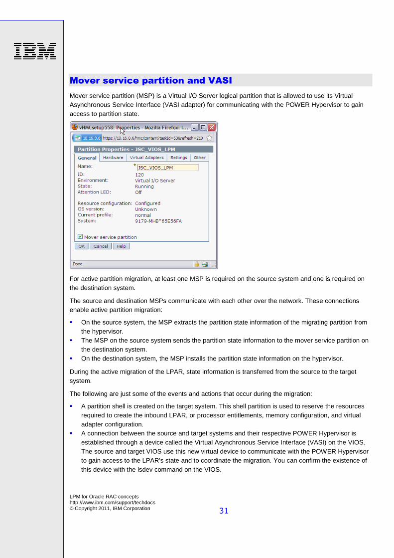
Mover service partition and VASI
Mover service partition (MSP) is a Virtual I/O Server logical partition that is allowed to use its Virtual Asynchronous Service Interface (VASI adapter) for communicating with the POWER Hypervisor to gain access to partition state.
For active partition migration, at least one MSP is required on the source system and one is required on the destination system.
The source and destination MSPs communicate with each other over the network. These connections enable active partition migration:
� On the source system, the MSP extracts the partition state information of the migrating partition from the hypervisor.
� The MSP on the source system sends the partition state information to the mover service partition on the destination system.
� On the destination system, the MSP installs the partition state information on the hypervisor.
During the active migration of the LPAR, state information is transferred from the source to the target system.
The following are just some of the events and actions that occur during the migration:
� A partition shell is created on the target system. This shell partition is used to reserve the resources required to create the inbound LPAR, or processor entitlements, memory configuration, and virtual adapter configuration.
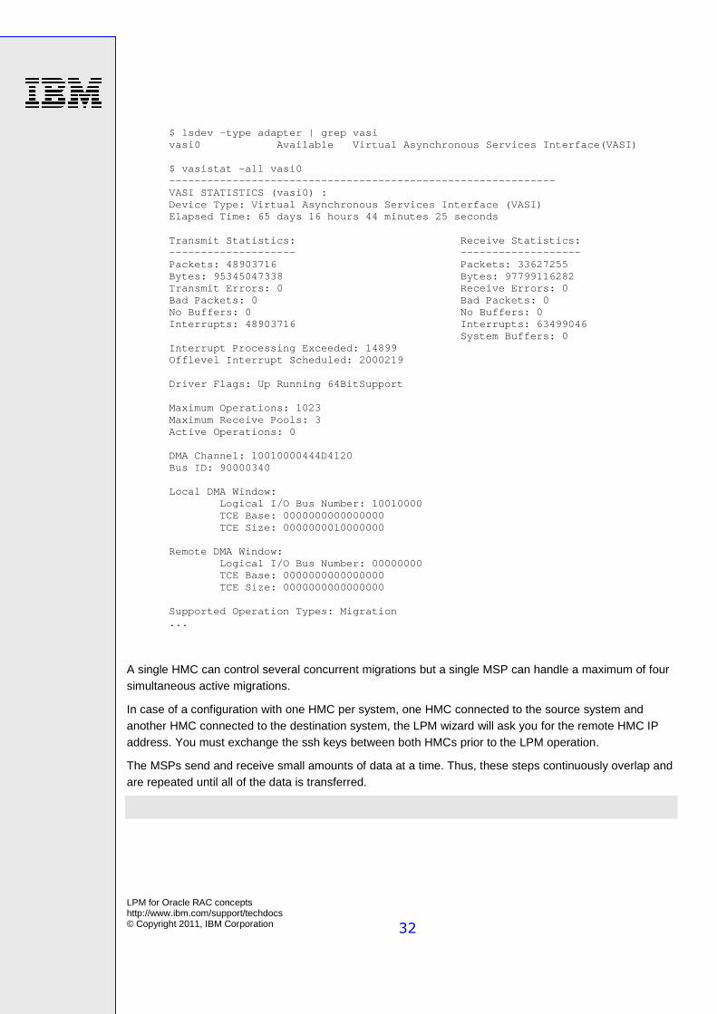
� A connection between the source and target systems and their respective POWER Hypervisor is established through a device called the Virtual Asynchronous Service Interface (VASI) on the VIOS. The source and target VIOS use this new virtual device to communicate with the POWER Hypervisor to gain access to the LPAR's state and to coordinate the migration. You can confirm the existence of this device with the lsdev command on the VIOS.
LPM for Oracle RAC concepts http://www.ibm.com/support/techdocs © Copyright 2011, IBM Corporation
32
$ lsdev -type adapter | grep vasi vasi0 Available Virtual Asynchronous Services Interface(VASI) $ vasistat -all vasi0 ------------------------------------------------------------- VASI STATISTICS (vasi0) : Device Type: Virtual Asynchronous Services Interface (VASI) Elapsed Time: 65 days 16 hours 44 minutes 25 seconds Transmit Statistics: Receive Statistics: -------------------- ------------------- Packets: 48903716 Packets: 33627255 Bytes: 95345047338 Bytes: 97799116282 Transmit Errors: 0 Receive Errors: 0 Bad Packets: 0 Bad Packets: 0 No Buffers: 0 No Buffers: 0 Interrupts: 48903716 Interrupts: 63499046 System Buffers: 0 Interrupt Processing Exceeded: 14899 Offlevel Interrupt Scheduled: 2000219 Driver Flags: Up Running 64BitSupport Maximum Operations: 1023 Maximum Receive Pools: 3 Active Operations: 0 DMA Channel: 10010000444D4120 Bus ID: 90000340 Local DMA Window: Logical I/O Bus Number: 10010000 TCE Base: 0000000000000000 TCE Size: 0000000010000000 Remote DMA Window: Logical I/O Bus Number: 00000000 TCE Base: 0000000000000000 TCE Size: 0000000000000000 Supported Operation Types: Migration ...
A single HMC can control several concurrent migrations but a single MSP can handle a maximum of four simultaneous active migrations.
In case of a configuration with one HMC per system, one HMC connected to the source system and another HMC connected to the destination system, the LPM wizard will ask you for the remote HMC IP address. You must exchange the ssh keys between both HMCs prior to the LPM operation.
The MSPs send and receive small amounts of data at a time. Thus, these steps continuously overlap and are repeated until all of the data is transferred.
LPM for Oracle RAC concepts http://www.ibm.com/support/techdocs © Copyright 2011, IBM Corporation
33
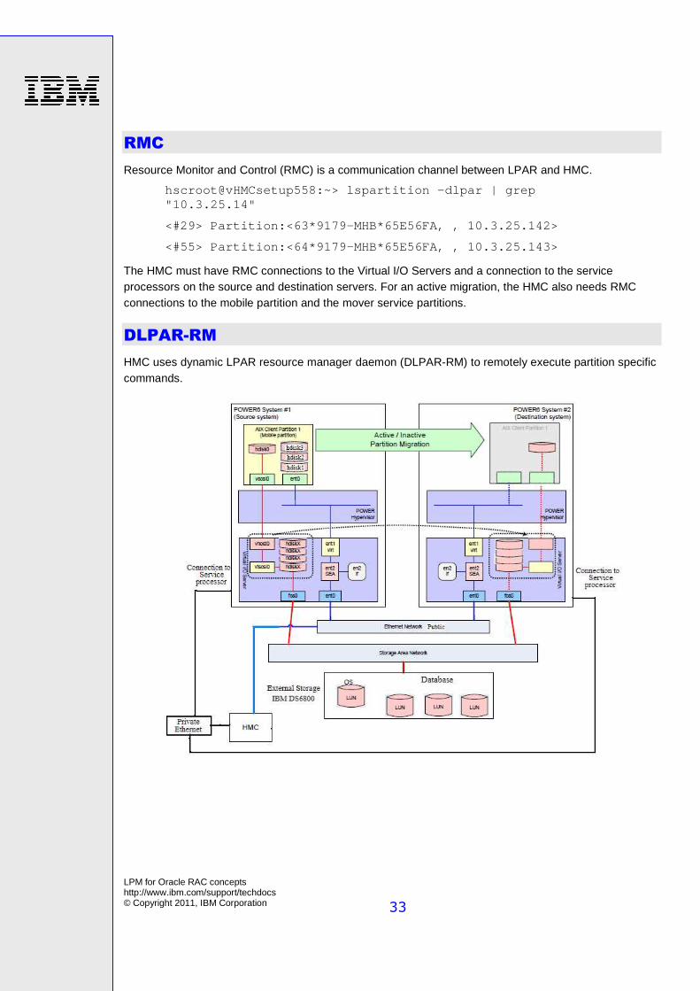
RMC
Resource Monitor and Control (RMC) is a communication channel between LPAR and HMC.
hscroot@vHMCsetup558:~> lspartition -dlpar | grep "10.3.25.14"
<#29> Partition:<63*9179-MHB*65E56FA, , 10.3.25.142>
<#55> Partition:<64*9179-MHB*65E56FA, , 10.3.25.143>
The HMC must have RMC connections to the Virtual I/O Servers and a connection to the service processors on the source and destination servers. For an active migration, the HMC also needs RMC connections to the mobile partition and the mover service partitions.
DLPAR-RM
HMC uses dynamic LPAR resource manager daemon (DLPAR-RM) to remotely execute partition specific commands.
LPM for Oracle RAC concepts http://www.ibm.com/support/techdocs © Copyright 2011, IBM Corporation
34
Making Programs DLPAR-Aware Using DLPAR AP
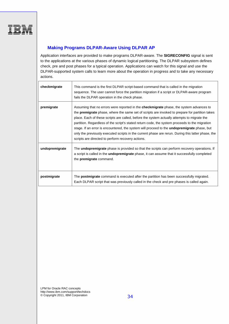
Application interfaces are provided to make programs DLPAR-aware. The SIGRECONFIG signal is sent to the applications at the various phases of dynamic logical partitioning. The DLPAR subsystem defines check, pre and post phases for a typical operation. Applications can watch for this signal and use the DLPAR-supported system calls to learn more about the operation in progress and to take any necessary actions.
checkmigrate This command is the first DLPAR script-based command that is called in the migration
sequence. The user cannot force the partition migration if a script or DLPAR-aware program
fails the DLPAR operation in the check phase.
premigrate Assuming that no errors were reported in the checkmigrate phase, the system advances to
the premigrate phase, where the same set of scripts are invoked to prepare for partition takes
place. Each of these scripts are called, before the system actually attempts to migrate the
partition. Regardless of the script's stated return code, the system proceeds to the migration
stage. If an error is encountered, the system will proceed to the undopremigrate phase, but
only the previously executed scripts in the current phase are rerun. During this latter phase, the
scripts are directed to perform recovery actions.
undopremigrate The undopremigrate phase is provided so that the scripts can perform recovery operations. If
a script is called in the undopremigrate phase, it can assume that it successfully completed
the premigrate command.
postmigrate The postmigrate command is executed after the partition has been successfully migrated.
Each DLPAR script that was previously called in the check and pre phases is called again.
LPM for Oracle RAC concepts http://www.ibm.com/support/techdocs © Copyright 2011, IBM Corporation
35
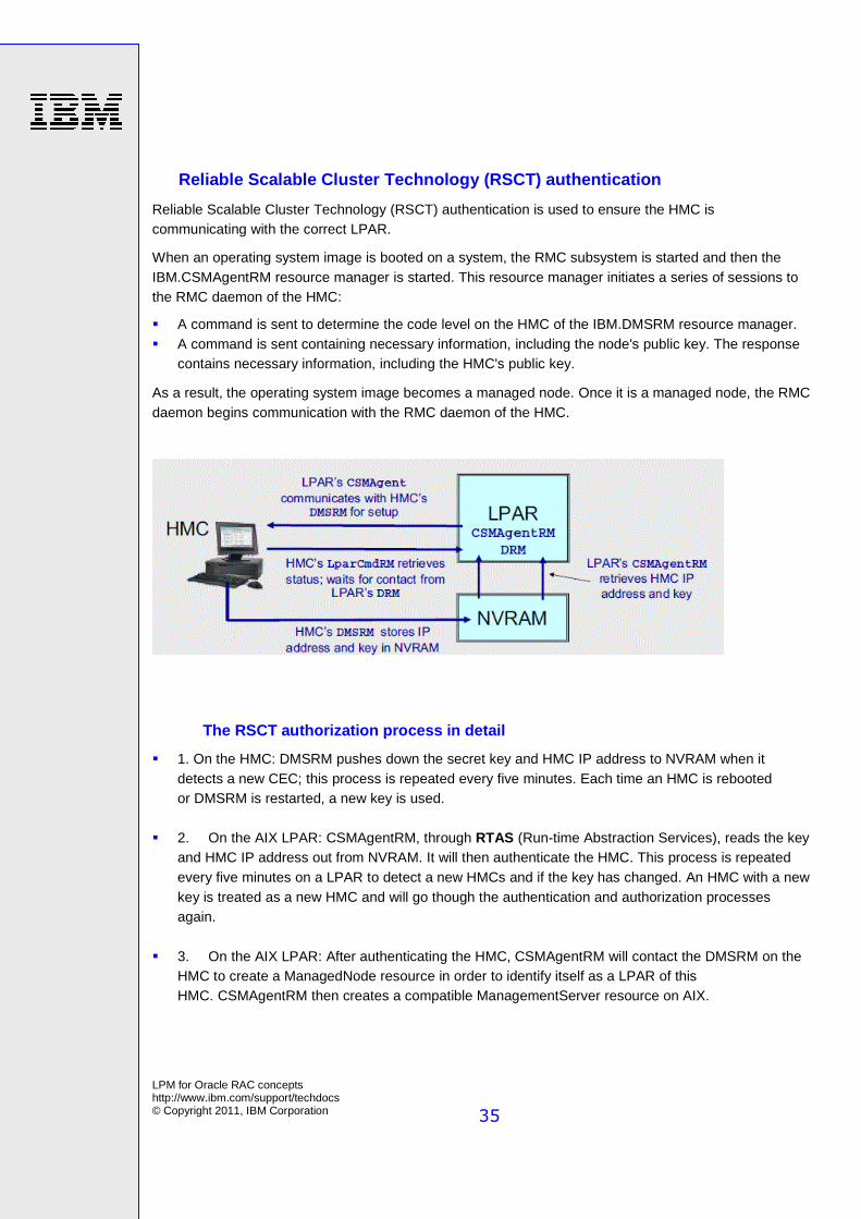
Reliable Scalable Cluster Technology (RSCT) authent ication
Reliable Scalable Cluster Technology (RSCT) authentication is used to ensure the HMC is communicating with the correct LPAR.
When an operating system image is booted on a system, the RMC subsystem is started and then the IBM.CSMAgentRM resource manager is started. This resource manager initiates a series of sessions to the RMC daemon of the HMC:
� A command is sent to determine the code level on the HMC of the IBM.DMSRM resource manager. � A command is sent containing necessary information, including the node's public key. The response
contains necessary information, including the HMC's public key.
As a result, the operating system image becomes a managed node. Once it is a managed node, the RMC daemon begins communication with the RMC daemon of the HMC.
The RSCT authorization process in detail
� 1. On the HMC: DMSRM pushes down the secret key and HMC IP address to NVRAM when it detects a new CEC; this process is repeated every five minutes. Each time an HMC is rebooted or DMSRM is restarted, a new key is used.
� 2. On the AIX LPAR: CSMAgentRM, through RTAS (Run-time Abstraction Services), reads the key and HMC IP address out from NVRAM. It will then authenticate the HMC. This process is repeated every five minutes on a LPAR to detect a new HMCs and if the key has changed. An HMC with a new key is treated as a new HMC and will go though the authentication and authorization processes again.
� 3. On the AIX LPAR: After authenticating the HMC, CSMAgentRM will contact the DMSRM on the HMC to create a ManagedNode resource in order to identify itself as a LPAR of this HMC. CSMAgentRM then creates a compatible ManagementServer resource on AIX.
LPM for Oracle RAC concepts http://www.ibm.com/support/techdocs © Copyright 2011, IBM Corporation
36
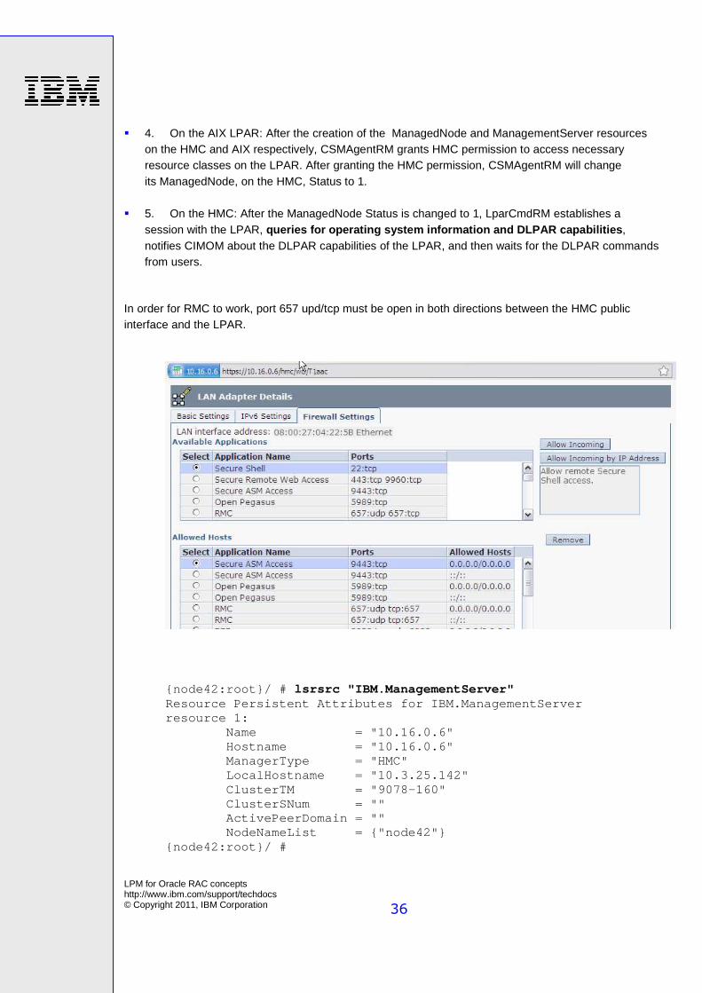
� 4. On the AIX LPAR: After the creation of the ManagedNode and ManagementServer resources on the HMC and AIX respectively, CSMAgentRM grants HMC permission to access necessary resource classes on the LPAR. After granting the HMC permission, CSMAgentRM will change its ManagedNode, on the HMC, Status to 1.
� 5. On the HMC: After the ManagedNode Status is changed to 1, LparCmdRM establishes a session with the LPAR, queries for operating system information and DLPAR capabilities , notifies CIMOM about the DLPAR capabilities of the LPAR, and then waits for the DLPAR commands from users.
In order for RMC to work, port 657 upd/tcp must be open in both directions between the HMC public interface and the LPAR.
{node42:root}/ # lsrsrc "IBM.ManagementServer" Resource Persistent Attributes for IBM.ManagementServer resource 1: Name = "10.16.0.6" Hostname = "10.16.0.6" ManagerType = "HMC" LocalHostname = "10.3.25.142" ClusterTM = "9078-160" ClusterSNum = "" ActivePeerDomain = "" NodeNameList = {"node42"} {node42:root}/ #
LPM for Oracle RAC concepts http://www.ibm.com/support/techdocs © Copyright 2011, IBM Corporation
37
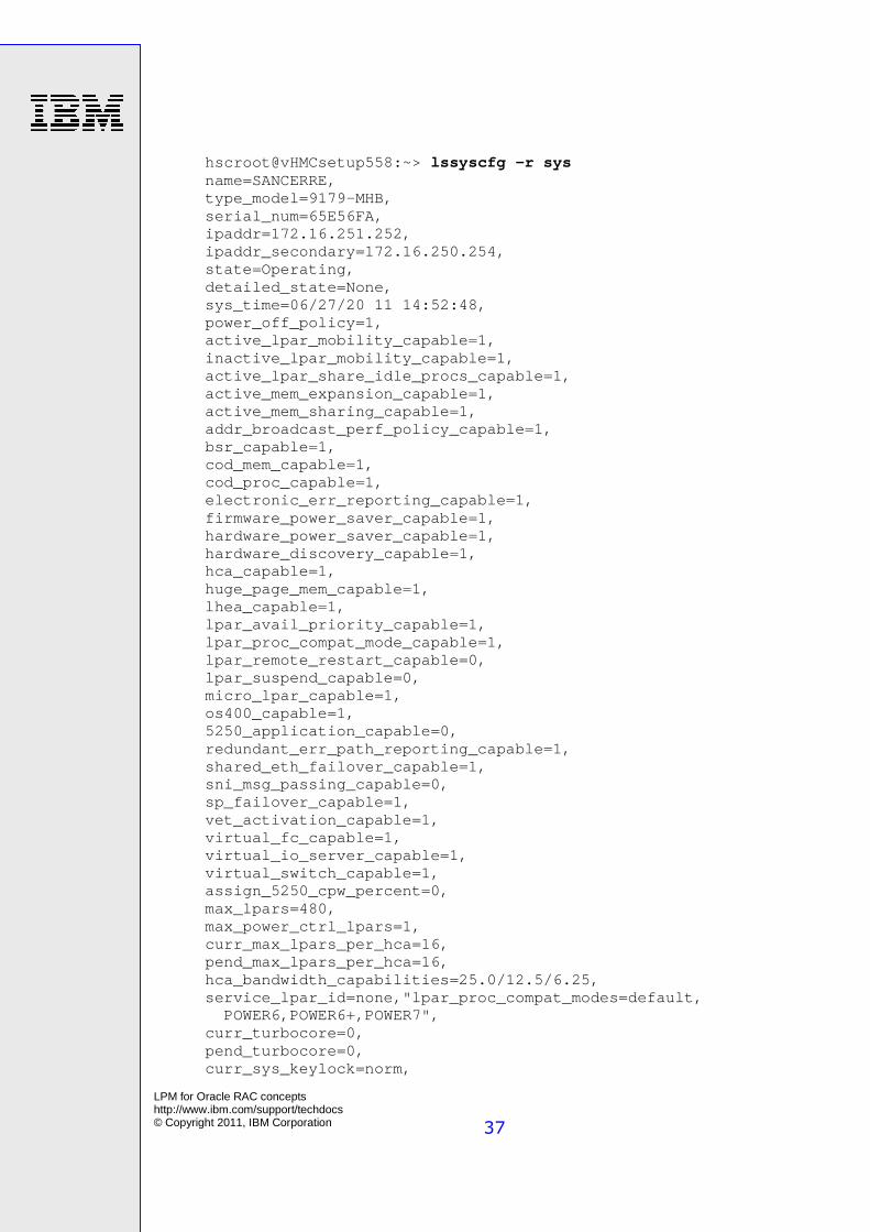
hscroot@vHMCsetup558:~> lssyscfg -r sys name=SANCERRE, type_model=9179-MHB, serial_num=65E56FA, ipaddr=172.16.251.252, ipaddr_secondary=172.16.250.254, state=Operating, detailed_state=None, sys_time=06/27/20 11 14:52:48, power_off_policy=1, active_lpar_mobility_capable=1, inactive_lpar_mobility_capable=1, active_lpar_share_idle_procs_capable=1, active_mem_expansion_capable=1, active_mem_sharing_capable=1, addr_broadcast_perf_policy_capable=1, bsr_capable=1, cod_mem_capable=1, cod_proc_capable=1, electronic_err_reporting_capable=1, firmware_power_saver_capable=1, hardware_power_saver_capable=1, hardware_discovery_capable=1, hca_capable=1, huge_page_mem_capable=1, lhea_capable=1, lpar_avail_priority_capable=1, lpar_proc_compat_mode_capable=1, lpar_remote_restart_capable=0, lpar_suspend_capable=0, micro_lpar_capable=1, os400_capable=1, 5250_application_capable=0, redundant_err_path_reporting_capable=1, shared_eth_failover_capable=1, sni_msg_passing_capable=0, sp_failover_capable=1, vet_activation_capable=1, virtual_fc_capable=1, virtual_io_server_capable=1, virtual_switch_capable=1, assign_5250_cpw_percent=0, max_lpars=480, max_power_ctrl_lpars=1, curr_max_lpars_per_hca=16, pend_max_lpars_per_hca=16, hca_bandwidth_capabilities=25.0/12.5/6.25, service_lpar_id=none,"lpar_proc_compat_modes=default, POWER6,POWER6+,POWER7", curr_turbocore=0, pend_turbocore=0, curr_sys_keylock=norm,
LPM for Oracle RAC concepts http://www.ibm.com/support/techdocs © Copyright 2011, IBM Corporation
38
pend_sys_keylock=norm, curr_power_on_side=temp, pend_power_on_side=temp, curr_power_on_speed=norm, pend_power_on_speed=norm, power_on_type=power on, power_on_option=standby, power_on_lpar_start_policy=userinit, pend_power_on_option=autostart, pend_power_on_lpar_start_policy=autostart, power_on_method=02, power_on_attr=0000, sp_boot_attr=0000, sp_boot_major_type=08, sp_boot_minor_type=01, sp_version=00070000, mfg_default_config=0, curr_mfg_default_ipl_source=a,pend_mfg_default_ipl_source=a, curr_mfg_default_boot_mode=norm, pend_mfg_default_boot_mode=norm
POWER Hypervisor
During the migration, the POWER Hypervisor provides the state of the LPAR to the Mover Service Partition.
The operation of Live Partition Mobility generates a communication between the HMC and the Hypervisor. The HMC calls the Hypervisor and it executes both informational and action commands.
The Hypervisor transfers the partition state through the VASI device to the Mover Service Partition.
Time reference partition (TRP)
The time reference partition (TRP) setting has been introduced to enable the POWER Hypervisor to synchronize the partition's time-of-day as it moves from one system to another. It uses Coordinate Universal Time (UTC) derived from a common network time protocol (NTP) server with NTP clients on the source and destination systems. More than one TRP can be specified per system. The POWER Hypervisor uses the reference partition with the oldest time as the provider of authoritative system time. It can be set or reset through POWER Hypervisor while the partition is running.
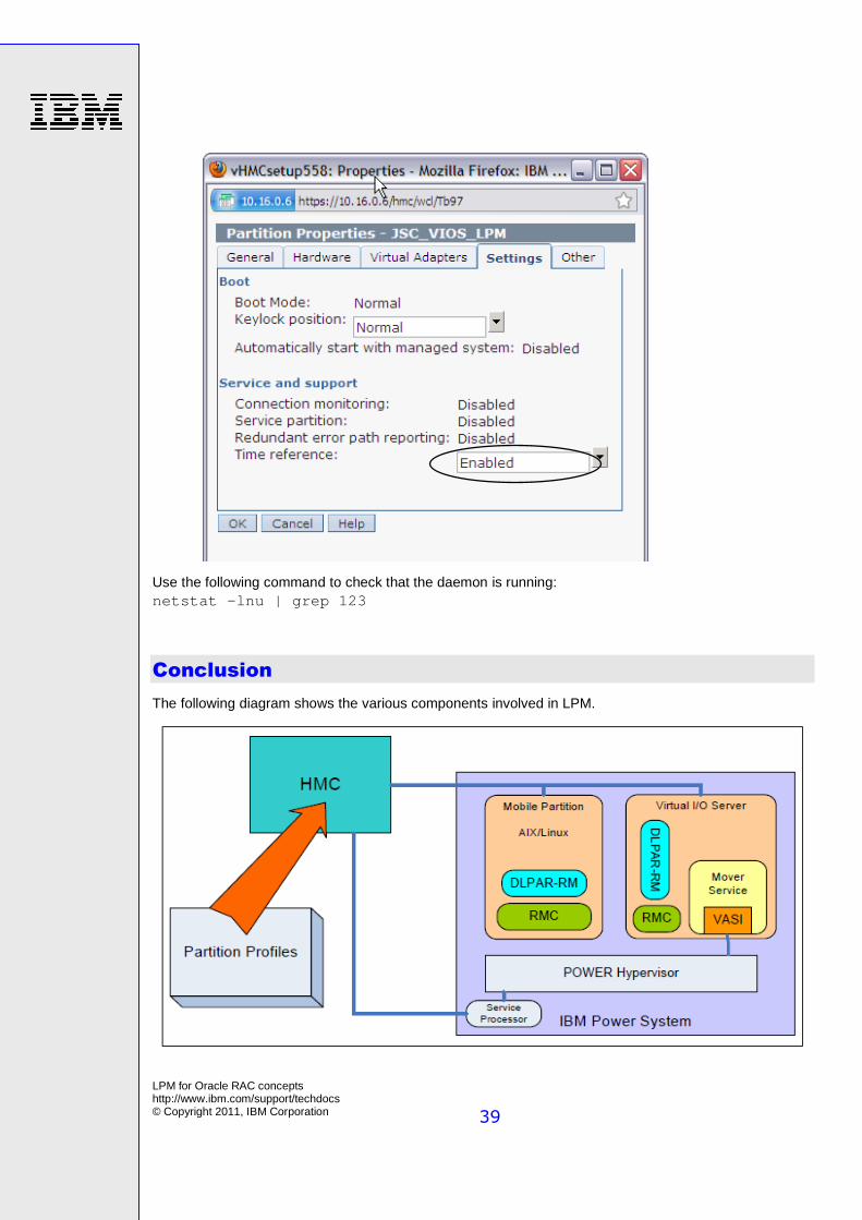
As an option, you can synchronize the time-of-day clocks of the VIO Servers on both source and destination servers. See the following Properties window as example.
LPM for Oracle RAC concepts http://www.ibm.com/support/techdocs © Copyright 2011, IBM Corporation
39
Use the following command to check that the daemon is running: netstat -lnu | grep 123
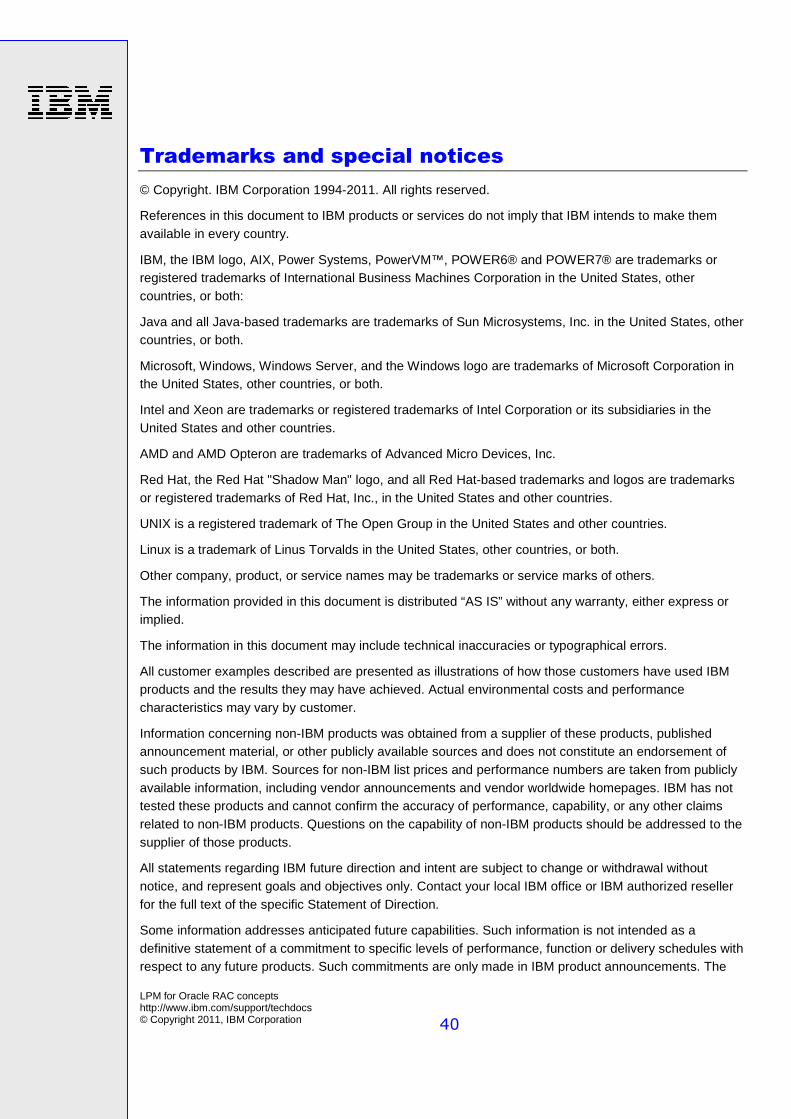
Conclusion
The following diagram shows the various components involved in LPM.
LPM for Oracle RAC concepts http://www.ibm.com/support/techdocs © Copyright 2011, IBM Corporation
40
Trademarks and special notices
© Copyright. IBM Corporation 1994-2011. All rights reserved.
References in this document to IBM products or services do not imply that IBM intends to make them available in every country.
IBM, the IBM logo, AIX, Power Systems, PowerVM™, POWER6® and POWER7® are trademarks or registered trademarks of International Business Machines Corporation in the United States, other countries, or both:
Java and all Java-based trademarks are trademarks of Sun Microsystems, Inc. in the United States, other countries, or both.
Microsoft, Windows, Windows Server, and the Windows logo are trademarks of Microsoft Corporation in the United States, other countries, or both.
Intel and Xeon are trademarks or registered trademarks of Intel Corporation or its subsidiaries in the United States and other countries.
AMD and AMD Opteron are trademarks of Advanced Micro Devices, Inc.
Red Hat, the Red Hat "Shadow Man" logo, and all Red Hat-based trademarks and logos are trademarks or registered trademarks of Red Hat, Inc., in the United States and other countries.
UNIX is a registered trademark of The Open Group in the United States and other countries.
Linux is a trademark of Linus Torvalds in the United States, other countries, or both.
Other company, product, or service names may be trademarks or service marks of others.
The information provided in this document is distributed “AS IS” without any warranty, either express or implied.
The information in this document may include technical inaccuracies or typographical errors.
All customer examples described are presented as illustrations of how those customers have used IBM products and the results they may have achieved. Actual environmental costs and performance characteristics may vary by customer.
Information concerning non-IBM products was obtained from a supplier of these products, published announcement material, or other publicly available sources and does not constitute an endorsement of such products by IBM. Sources for non-IBM list prices and performance numbers are taken from publicly available information, including vendor announcements and vendor worldwide homepages. IBM has not tested these products and cannot confirm the accuracy of performance, capability, or any other claims related to non-IBM products. Questions on the capability of non-IBM products should be addressed to the supplier of those products.
All statements regarding IBM future direction and intent are subject to change or withdrawal without notice, and represent goals and objectives only. Contact your local IBM office or IBM authorized reseller for the full text of the specific Statement of Direction.
Some information addresses anticipated future capabilities. Such information is not intended as a definitive statement of a commitment to specific levels of performance, function or delivery schedules with respect to any future products. Such commitments are only made in IBM product announcements. The
LPM for Oracle RAC concepts http://www.ibm.com/support/techdocs © Copyright 2011, IBM Corporation
41
information is presented here to communicate IBM's current investment and development activities as a good faith effort to help with our customers' future planning.
Performance is based on measurements and projections using standard IBM benchmarks in a controlled environment. The actual throughput or performance that any user will experience will vary depending upon considerations such as the amount of multiprogramming in the user's job stream, the I/O configuration, the storage configuration, and the workload processed. Therefore, no assurance can be given that an individual user will achieve throughput or performance improvements equivalent to the ratios stated here.
Photographs shown are of engineering prototypes. Changes may be incorporated in production models.
Any references in this information to non-IBM Web sites are provided for convenience only and do not in any manner serve as an endorsement of those Web sites. The materials at those Web sites are not part of the materials for this IBM product and use of those Web sites is at your own risk.