ljj~ oo~ - nasa · pdf file2.0 transmitter figure 2-1 is a photograph of the transmitter...
TRANSCRIPT

""--=I~~~~~~
~~~~~(lJJ~ OO~
~@~~@~~~Jl@~
ELECTRONIC SYSTEMS DIVISION
(NASA-CR-122375) NI"BUS 4/IRLS BALLOON N72-21410INTERROGATION PACKAGE (BIP) Final Report(General Instrument Corp.) Oc~. 1971 89 P
CSCL 14B UnclasG3/14 23753
t',
https://ntrs.nasa.gov/search.jsp?R=19720013760 2018-05-14T11:08:40+00:00Z

FINAL REPORT
NIMBUS 4/IRLS BALLOON INTERROGATION
PACKAGE (BIP)
Prepared for:
National Aeronautics and Space AdministrationGoddard Space Flight CenterGreenbelt, Maryland 20771
Contract No. NAS5 - 21110
Details -of illustrations inthis document ma~ be. better
~udied on mwrohche
Prepared by:
General Instrument CorporationElectronic Systems Division
Hicksville, New York
October 1971
\
STAI(
.~

':"'~,f',CEDING PAGE BLANK NOT FILMED
TABLE OF CONTENTS
5.0 ELECTRONICS SUB-ASSEMBLY, WATER BAGS, ••••AND BATTER:\[ PACK•••••••••••••••••••••••
SECTION
1.0
2.02.12.22.32.4
3.03.13.23.33.4
3 .. 5
4.0
5.15·':.~
5.3
6.0
7.0
DESCRIPTION
INTRODUCTION•••••••••••••••••••••••••••••
TRA.NSMITTER••••••••••••••••••••••••••••••Di..plexer •• _•• '•••••••••••••••••••••••••• '••Low Level ••••••••••••••••••••••••••••••••Multiplier'•••.•..•••. ~ .•.••.••..••.•....•Power Amplifier •••••.••.•••••••••••••••••
RECE IVE.R •••••••••••••••••••••• '. • • • • • • • • •Housing•••••••••••••••••••••••..•••••••••Local Oscillator •••••.•••••••••••••••••••RF and Multiplier Assemblies •••••••••••••First IF, Second IF, and Video•••••••••••
Assemblies ••••••.•.•.•...••.•••..•.••••Specia.1. Radio Set Tests ••••••••••••••••••
ANTENN"A .
Electronics Sub-Assembly•••••••••••••••••Water Bags ••••••••••••••••••••••••••••••'.Bat te-ry Pack. •••••••••••••••• _••••••••••••
BIP HOUS INGo ••••••••••••• _ •• _ ••••••••••••
ENVIRONMENTAL TESTS ••••••••••••••••••••••
PAGE
1-1
2-12-12-12-42-4
3-13-13-13-1
3... 43-6
4-1
5-15-15-105... 10
6-1
7-0
8.0 BALLOON LAUNCH SERIES NO.1 (MAY, JUNE,.AN'D JULy 1.970).......................... 8-1
9.0 BALLOON LAUNCH SERIES NO. 2 (OCTOBER ANDNOVEMBER 1970} •••••••••••••••• o........ 9-1
10.0
10.110.210.3
11..0
LOSS OF EXTERNAL TELEMETRY SENSOR••••••••INFO.R..l\tIATION 0 •••••• _ .••
Tes t Program.•••••••••••••••••••••••••••••Balloon Launch Series No.2 ••••••••••••••PIS, BIP Recovered from Africa•••••••••••
REAL TIME TWO SECOND TIMER•••••••••••••••
10-110-110-310-5
1h·1
Appendix I - Calculation of PIS Channels 2, 3, and 4Voltages for Day 11/2/70, Orbit 2794
Appendix II- Specification 121765
ii

FIGURE
2-1
2-2
3-1
3-2
3-3
3-4
4-1
4-2
4-3
4-4
4-5
4-6
4-7
4-8
4-9
4-10
4-11
4-12
4-13
4-14
4-15
4-16
4-17
4-18
4-19
4-20
5-1
5-2
5-3
LIST OF ILLUSTRATIONS
Transmitter and Receiver Assembly •••••••••••••.•
Transmitter Schematic Diagram.••••••.••.•.••••••
BIP Receiver .
BIP Receiver - Cover Removed••••••••.•.••.••••••
Receiver Schematic Diagram••••••••••••••••••••••
Time Delay variation Test Set-Up••••••••••••••..
Antenna Gain at 401.5 MHz •••.••.•••••.•.•.•.•.•.
Antenna Gain at 466 MHz •••.•..•••..•••••••••••••
Polarization Pattern, 401.5 MHz, 15° •••••.••••••
Polarization Pattern, 401.5 MHz, 45° •••.••••••.•
Polarization·Pattern, 401.5 MHz, 75° •••••••••.••
PolaJ:ization Pattern, 466 MHz, 15° ••.•••••••••
Polarization Pattern, 466 MHz, 45° •••••••••••.
Polarization Pattern, 466 MHz, 75° ••••••••••••
Directional Pattern, 466 MHz, E-P1ane, 0° •••...
Directional Pattern, 466 MHz, E-P1ane, 45° •.•.•
Directional. Pattern, 466 MHz, E-P1ane, 90° ...••
Directional. Pattern, 466 MHz, H-P1ane, 0° •.•••
Directional Pattern, 466 MHz, H-P1ane, 45° •••••
Direct,lonal. Pattern, 466 MHz, H-P1ane, 90° ....•
Directional. Pattern, 401.5 MHz, E-P1ane, 0° .•••
Directional. Pattern, 401.5 MHz, E-Plane, 45° ...•
Directional Pattern, 401.5 MHz, E-P1ane, 90° .•••
Directional. Pattern, 401.5 MHz, H-P1ane, 0° ••.•
Directional. Pattern, 401.5 MHz, H-P1ane, 45° .•••
Directional Pattern, 401.5 MHz, H-P1ane, 90° ••••
BIP Rlectronics Unit ••••••.•.•.•.•...••.••••.•••
Bit Synchronizer, PCMDemodulator, Sync Demodulator, and CorrelatorDetector Schematic Diagram•••••.•..••..•.•..••
Programmer, Address Register and Corre1atorParity Generator, and Modulator Schematic
PAGE
2-2
2-3
3-2
3-3
3-4
3-7
4-5
4-6
4-7
4-8
4-9
4-10
4-11
4-12
4-13
4-14
4-15
4-16
4-17
4-18
4-19
4-20
4-21
4-22
4-23
4-24
5-2
5-3
o i.agram.. • • .. • • .. .. • • • • .. . . • .. .. . • • • • • .. • • . • . .. .. . • • • .. • .. 5-4
5-4 Forma,tt:er, Multiplexer. and Coder SchematicD i.agr,am. " ".0. .. .. • 5-5
iii

FIGURE
5-5
5-6
6-1
10-1
10-2"
LIST OF ILLUSTRATIONS (Continued)
Power Control and Premodu1ation , ••••••••••••Filter Schematic Diagram••••••••••••••••.••
voltage Regulator Schematic Diagram••••••••••
BIP Electronics Unit •••••••••••••••••••••••••
Typical Multiplexer FET••••••••••••••••••.•••
External Telemetry Sensor Relay••••••••••••••Board Schematic •.............•............•
5-6
5-7
6-210-7
10-8
10-3
10-4
11-1
11-2
Recovered BIP Electronics Unit ••••.•••••••••• 10-9
Recovered BIP Solar Panel ••••••••• ~ •••••.•••• 10-10
Two Second Timer Schematic Diagram••••••••••• 11-2
Two Second Timer Printed Circuit Board••••••• 11-3
iv

1.0 INTRODUCTION
The Balloon Interrogation Package (BIP), an integral
part of the overall Interrogation, Recording, and Location
Subsystems (IRLS) for the Nimbus 4 program, was produced by
the General Instrument corporation/Electronic Systems Division,
Hicksville, New York, for the National Aeronautics and Space
Administration, Greenbelt, Maryland, under contract number
NAS5-21l10. The BIP is a self-contained, integrated transponder
designed to be carried aloft by a constant altitude, super
pressure balloon to an altitude of 67,000 or 78,000 feet. After
launch the BIP senses high-altitude balloon overpressure and
temperature, and upon receipt of an interrogated command from
the IRLS aboard the Nimbus 4 satellite, the BIP encodes the
data on a real-time basis into a pulse-code modulation (PCM)
format and transmits this data to the satellite.
The Nimbus 4!IRLS Balloon Interrogation Package
experiment was highly successful in delivery of equipment,
Ascension Island support, and equipment flight life. Extensive
meteorlogical data was obtained from the many BIP balloon flights;
some of which had made many revolutions of the earth at the
equator. While the reduction and analysis of the balloon flight
data will take an extended period of time, there is no doubt
that the results of this program will significantly contribute
to the understanding of the upper atmosphere.
This final report presents a summary of the program
activity to produce thirty BIP systems and to support balloon
launches from Ascension Island.
1-1

2.0 TRANSMITTER
Figure 2-1 is a photograph of the transmitter assembly,
the receiver, and interconnec.tion cable. The complete
transmitter schematic is shown in Figure 2-2.
2.1 Diplexer
The 3 pole filter and the 5 pole filter which comprise
the dip1exer were not changed electrically, however, extensive
mechanical changes were implemented. Instead of machining the
housings for these two units out of a solid block of aluminum,
inv~stment castings were used. This technique reduced the cost
and ensured uniformity of units. Previously the coils were dip
brazed to the housing. This technique presented problems, such
as an elaborate fixture to prevent heat distortion, as the housing
and the coil must be subjected to 1100°F for dip brazing. The
diplexer coils are now dip brazed to an aluminum flange which in
turn is fastened by screws to the side wall of the housing. These
mechanical changes resulted in a smooth production test of the 3
pole and 5 pole filters.
2.2 Low Level
Two resistor-thermistor networks are used to temper
ature compensate the VCXO for center frequency and deviation
sensitivity. Previously, decade resistor boxes in conjunction
with many temperature runs were used to synthesize each network.
Obviously this method would be too laborious and expensive for
2-1

Page intentionally left blank

production; therefore a computer program was developed to
synthesize the required networks. After the initial debugging
of the computer program, the vcxo temperature compensation
became a routine production test.
2.3 Multiplier
The X4 multiplier was completely redesigned to
eliminate the previous design limitations and tuning difficulty.
The technique of a floating printed circuit board ground was
used. This eliminated an empirically derived emitter tuning
network which could not be controlled in production. Also the
new design provided a test point between the first and second
multiplier that made the alignment relatively simple. Each
multiplier stage is aligned separately with a signal generator
and then the two are cascaded together. The new multiplier also
has an RF power output safety margin of 40 mi1liwatts minimum.
2.4 Power Amplifier
The power amplifier was not changed other than some
minor decoupling modifications.
The output stage of the power amplifier uses a 2N443l
overlay transistor. These devices were originally purchased
from Solid state Scientific (SSS) for the thirty production
units. It was found, however, that the "SSS transistors were
very sensitive to load VSWR variations. An increase in VSWR
from 1:1 to 1:12 or 1:13 would in most cases cause the transistor
2-4

to fail. For the development contract, these transistors were.
purchased from TRW and were not load sensitive. Investigations
revealed that while the SSS 2N443l met the JEDEC specifications
it had a typical VCEO of 45 volts, just over the specified
minimum. However, the TRW 2N443l has a nominal VCEO of 60 volts.
This higher VCEO allows the TRW 2N443l to withstand the varia
tion in load VSWR without damage. The SSS 2N443l transistor
was replaced with TRW transistors and no further difficulties
were encountered.
2-5 .

3.0 RECEIVER
Figure 3-1 and 3-2 are photographs of the BIP receiver.
A complete schematic of the BIP receiver is shown in Figure 3-3.
3.1 Housing
As in the case of the 3 pole and the 5 pole filters,
the receiver housing was not machined from solid aluminum, but
an investment casting was used.
3.2 Local Oscillator
The 37 MHz crystal oscillator was purchased from
Frequency Electronics. This compact unit is very similar to one
of its product line items, and as in the past this item has
worked well with no problem areas.
3.3 RF and Multiplier Assemblies
The preselector had minor modifications. For example,
the neutralization loop was removed as it proved to be a source
of instability under variation of driving source L~pedance.
The gain difference, with and without neutralization, was
negligible. Additional supply line decoupling was added to
the XlO step recovery diode multiplier to ensure stable opera
tion over all conditions (C217, RFC20l, and RFC202 as shown
in Figure 3-3). The multiplier output tapped coil was changed
3-1

3-7

L..
....
NI
0')
3-3

G
FOLD
out
ER
AM
EI7
•6
\ L
5,
\
"
G
F E ,0 c
, ,
I ,
"
-,,;.."
F ,0 c
B

to top capacitive loading. Small turn, tapped coils are too
difficult to control in production.
3.4 First IF, Second IF, and Video Assemblies
The First IF amplifier, the Second IF amplifier,
and the video amplifier had minor circuit component
modifications. The input impedance of the power switch which
is located in the video assembly printed circuit board was
reduced to lOOK ohms (see Figure 3-3). This change was
implemented, per NASA's direction, to reduce the possibility
of "pick-up" in this high impedance circuit.
3-5

3.5 Special Radio Set Tests
A time delay variation vs. incoming frequency signal
level, and temperature study was conducted during the initial
phases of this contract. First a new method of measuring time
delay variation was perfected. Previous to this contract, time
delay variation was measured on an oscilloscope by observing
,the raw video signal out of the receiver. At low signal
levels the video signal is, of course, very noisy, thereby
making accurate time delay variation measurements very diffi
cult~ if not impossible. Figure 3-4 shows the test set-up of
the new method devised under this contract. By using the bit
synchronizer, located in the electronics sub-assembly, the re
constituted video signal is observed on the oscilloscope. This
new method also measures the time delay variations of the bit
synchronizer l as well as the BIP receiver. Using this method
the total time delay variations of GFE receivers #32401 and
#32403 was 1.3 a~~ 0.8 ~sec, respectively. BIP SiN 004 bit
synchronizer was used for these measurements. All production
BIP receivers had time delay variations of less than ±1.0 ~sec.
During the months of December 1969 and January 1970
GFE BIP systems #002 and #003 were interrogated approximately
10,000 times. This investigation was initialed, at NASA's
direction, in order to try to simulate the "transmitter turn-on,
receiver turn-off" phenomenon that was claimed occurred in
the BIP animal pack.
3-6

100 Kl4l. '.25KU! MAR.COlJl ~p 355 c. \4P '3SSC-:- fb - f-+ - i--
CLOCK T~ IO"~B ATT A'TT-
.RF IN
--_.."- BfP
-RE.C.e:tVi.R.
Jl_~-~- "- A~ VIO~Q
OUT -. ..-
+45V -:L- .'. -- -- A.Z-J' - 32-
-
.BrT-~Y~c.. -
AZA4
1. -..
B'P Te.:~T SE.T
TP3
c.1-\ A \>J BEx,r.S'("!c. _ .
TE.X TRONi<:..
OS C.ILLOSc..OP£ -
.CHAN A. -
t='IGdJRE:. 3-4-. TIME.. DE.I..A.Y VARIA,itON TEST SET- UP3-7

It was further claimed that RF energy from the BIP transmitter
was causing the BIP receiver power switch to turn-off. This
problem manifested itself by a normal receiver liON" cycle
(97.5 msec) after BIP 'interroga~ion, instead of the normal data
frame transmission. However, the normal data frame transmission
always occurred when the receiver turned on the second time.
In investigating this problem it was observed that address
correlation did not occur when the receiver recycled, therefore
the transmitter power could not corne on. The problem appeared
to be in the address correlator.
Discussions with R. Morrison, Radiation, Inc.
engineer, brought to light the fact that this was a statistical
phenomena that had been observed in the past. This phenomena
is due to the positions of the phase locked loop in trebit
synchronizer and the receiver "on-time ll• Thus, when the
'-receiver "on-time" is at the minimum specified width (90 msec)
and the frequency difference between the incoming signal and
the phase locked loop oscillator is large, the probability of
missing an address correlation is highest. This WDuld only be
a system problem if a data frame transmission is not completed
in 3.6 seconds which may occur if the sic transmitter turns on
at or near the end of the receiver "on cycle". The diagram
shown on the following page illustrates this point if it is
assumed that the sic transmitter turns on at the end of the
first receiver on period, and address correlation is not made
during the second receiver on period. Thus, the total time
3-8

before the receiver will turn on again is 1.795 + 0.090 + 1.795,
or 3.680 sec.
RECE IVER DUI'Y CYCLE
OFFON ON OFF ON
J I J [I 1--- --Jt--1.795sec.--2-111.....,;,...... >;<;--1.795 sec.--
sic transmitter 0.090 sec.Turns On
Since the sic transmitter is programmed to turn off if the BIP
address is not received in 3.6 seconds, an unsuccessful data
link would result.
During the above described investigations the receiver
was subjected to conducted and radiated RF power from 10 to 480
MHz to try to simulate the BIP animal pack problem. No degrad-
ation of receiver or transmitter performance was observed.
3-9

4.0 ANTENNA
In the early part of December 1969 a subcontract was
placed with the Technical Appliance corporation (TACO), a
division of the General Instrument Corporation, to manufacture
thirty (30) BIP antenna systems. A GFE BIP antenna (manufactured
by Radiation, Inc.) was shipped to TACO for testirtg in order to
determine conformance to paragraph 3.4.2 of GSFC specification
S-733-P-8-A dated May 1969. The salient requirements of this
specification are listed below.
1. The antenna must be right circularly polarized and
have a bifolium shaped power pattern.
2. The transmitting frequency shall be 466.0 MHz. The
receiving frequency shall be 401.5 MHz.
3. The input VSWR shall be 1.5/1 or less.
4. The axial ratio shall be less than 3 db over the
pattern of interest (between 15 and 75 degrees above the
horizontal.
5. The gain of the antenna over isotropic shall be at
least 5 db. The 15 to 75 degree elevation angle gains are 3 db
and 0 db respectively. At angles below 15 degrees, the anteJ.,nna
gain should drop abruptly.
However, it was agreed that as a minimum the BIP
antennas, as manufactured by TACO, would conform electrically
to the performance characteristics of the GFE BIP antenna.
4-1

TACO reported to General Instrument Corporation
that their evaluations of this GFE BIP antenna showed that
it was tuned to 460 MHz rather than 466 MHz. This fact was
uncovered after most of the evaluation data had been taken.
This GFE BIP antenna had an axial ratio greater than 3 db
at 466 MHz and low gain both at 401.5 MHz (15 0 from horizontal)
and at 466 MHz (all elevation angles). At NASA's direction,
Radiation was consulted in order to determine if this was a
representative sample of the Radiation manufactured antennas.
Radiation agreed that the axial ratio data that TACO measured
was representative of the data that they had measured. Also,
the directional pattern data measured by both firms were
almost identical. As for the antenna gain, Radiation used
the technique of pattern integration (directional pattern) ,
instead of absolute gain measurements, to calculate the gain.
For this calculation, Radiation assumed a cable loss, axial
ratio, and other losses to arrive at their predicted gain.
However, TACO measured the gain of the BIP antenna by comparison
with a linearly polarized standard gain antenna. TACO then added
3 dB to these measurements as the BIP antenna is circularly
polarized. Both TACO and Radiation agreed that the gain
comparison measurements would be more accurate if the linear
elements were considered separately. Since this antenna was
tuned at 460 MHz; and possibly damaged, no further measurements
were made.
4-2

Data (Figures 4-1 through 4-20) obtained from the first
TACO built plDduction antenna ~are included at the end of this
section.
First, a brief description of the figures is. given:
Figure 4-1 The BlP element gain is compared to a standard
gain antenna (+2.7 dBi) at 401.5 MHz in the E-plane.
Figure 4-2 The BlP element gain is compared to a standard
gain antenna (+2.7 dBi) at 466 MHz in the E-plane.
Figure 4-3 through 4-8 These polarization patterns of the
BlP antenna were obtained by periodic electronic switching of
the E & H plane of the illumination antenna while rotating the
BlP antenna about the symmetrical axis. The axial ratio at any
angle is obtained by measuring the maximum to minimum excursion
during a switching period. The table below summarizes the
pertinent data relating to these figures.
Figure No. Frequency MHz MaximumAxial Ratio/dB
Ground. Plane AngleDegrees
through 4-20 show the directional patterns
4-3 401.5
4-4 401.5
4-5 401.5
4-6 466
4-7 466
4-8 466
Figures 4-9
of the BlP antenna.
1.9
1.9
3.1
3.0
3.9
15.5
15
45
75
15
45
75
4-3

The test variables for these patterns were:
1. Frequencies of 401.5 and 466 MHz.
2. E and H plane illumination.
3. Axis of symmetry angle. >
The directional patterns were generated by rotating the BIP
antenna about a ground plane diameter. The table below
summarizes the test conditions of these figures.
Figure No. Frequeney,MHz Plane Axis of Synunetry Ang1e,Degree
4-9 466 E 0
4-10 466 E 45
4-11 466 E 90
4-12 466 H 0
4-13 466 H. 45
4-14 466 H 90
4-15 401.5 E 0
4-16 401.5 E 45
4-17 401.5 E 90
4-18 401.5 H 0
4-19 401.5 H 45
4-20 401.5 H 90
4-4


!.
t I,'
.'
· ::
[ .
\ ";
, ./ .I
1 ".1
\..,
'j
· .· !
; :
\ "

·~ ,
",, ,, .I.'
' .., ,
I
f /.
",
1 '
.\
o

, ,, I
, I
" '; ,
"':.
\
\


'\
11
111
•.11I11...uw
1
Ic(
c
1I-, .
I
o


~7·
~~~~~~~~~~~~~~~~.~~
-'_
,'_
."_
0._
_E
_P
RO
~'1G_
_•~E'4A~
--
--
.'-~
-
2i-~:"
'Q-K~i
:--=
~-=-
~~..;c
··;;j:\
·'li'~W
t'L\l
q-w.
:'Ll.
L;-\-:;:;
r~'~'~
~',;-+
-;:'\
i-:+
-,~'
-.-:-
~.-'~~
'::'f;;:
t:'~.:r
,-:f-
--"
','"
~_.~.'
~·-·~L
-:-··t
--"':
::.~':
."-=
.,:..!
:=:'~r-:
---.;..--~
.'o
;---E
-;----
'~.-.,
"""r
!'rn
,I~m'If
'fr
UtE
ti.'F~
'ftl~~
1TW
'..
~,..•
•-...
~.~'
•...,..
.Tr~
.L_t
;;--=r
;:~,.L
-.....£'
-,~
--~·r·
--··.,
-·t---
r=_·
L..,.
-.-~r'
.r.---f-~
-~._-
'-r--
..-_.,~
..(
-._1
._
I,rr
-'f"
t~·
-l·-
lli
,t"-
r~~
1=II
-I'
"'I
rLf-
r;!T
t.
--'
--"
'"-:-
r-r-,
,,~,I
','_',-j
,-
..
-1
.---
:...
.--'-~-
•r
----.--
-...
,_·:-,."--~,rIJ:rI··:r
,-;-
-tr
¥;-
iTfL
fiii
rj~
,rr
-':;
..::":.
.:...;::
'.·~"''''iC
-+j4
.L:-
fr,+
t.1-"'i~"
--;--;
rr
,;-,-
r.:::
-.
---t:o
..._-
---
'-~-~--
---
,---
·----·1
~....
'':
;~f~
;-~tfF:
'·~~
;:·"
'-=~
;:jh
-;'c
~.:~
~lf-HjYl±~~.
L&,1!ih~
c,f--L
Rit~'~,~,·-8r~.~~
>:r
~-~~r:-~;-~
----...=
-..;:::
---':':':':':~,
;-;:~:
-H-
:-:-
---.
.==:
'C'::
t--==
-I~
NU
~_··
I'-'
T·r-:
r-:·..·
,,,"
,.:-
-::-
:-__
e-!,~..:
II"
'~rl
,:J:.L
~'T
.t.!..tl
t}+-
J-,..,..,
.b.J::"
_.u;
:q:::
::....
..,.;
.,-.~-
,..
.._-
._1=
-1T
't·
~..._-
~t----'-"
·-i-fr
·,··--F~
-.-.,-
..'"--
--.-.-
.-....
0-0
1-~-
.i::.:.
:f,:::
:=..-
:.t.:!
.jl,.~
::"::
:':l~j
:\u';;
=t:.:;~I~P-
·7r1.1 .
':':-:l
.f.~.
!..L:
:.;.:[-1
,.:L
i.e:''1
..--=I
.::~:;
::!~I=-;T'
-c.::u
.;::..'1
:!.l:.:c
--.:~..
.:.:.
'-~=::
:.-=:
-...:.."
:.::.:
'=".
2::
.::..!
~.:tJ
.L.-..
.,.,'
,-=-
=~_.:-:..
--=.
r::.:=
-=:-
-:1
~_
.__.
.1
----
,-,~-
-,t-
;-;_
.-r=
:-,·
jrl.f
If"~'
_.
"I
-LC
CO
"Ti
r':D
I--r
,~
,---
-----
-1.
.!...
-_..
....
---'
I-
----'------I
\-~,t
'·,'
:-;-
th,"
:\"
,·t;;
!-;I·'
"-i'~=.~r
'1,:
'Y
;r.
r-++-
,',
L,-rr
-,~
'-II
'r"
Ir"
"-1..
.Lt'7~'7
I..:+
',-
-*-'
0-;"
,--
•,••
;...~
,,--,-
-~'-"-"S-·~-_·t--I--':'-·'I
..
•~~
-t-
-._--
r---
-t:-
..-l'{
._..
,.--
---;
--rr
tT
rT[T
W.!:.
.:.'-r
!+r·~r
UC
·'0
·;-~
r··-
.~-'-l
-U'--L.
.....l-
,-r
,--:-
--~
_.l
-...
__.
J.,
I~-
--1
---
-~._---
i'~~
"_;"
"--
'-p
".'.
"-",
..'
I",
r'
L':
;""ff
i-''
,1:,
1r·
1I~
P1r;
-j"
r~'-
~t
~·I·,r,·
;Tl.
:;"
c:~
•.-'
-,.-.-
_Ltt'1 '
;;.;
"l;.
ff.:
--'-
-I.;
.._
L..
.._
-_·-
-'t-
--'.
.-,
·_-
-lII
oIr--
....
-I~·
~.!-
~r---o
-'-jo;
...l.
"''''-
r'j'r
l .1
t-"'-
~lli
-.-
t°;-"
._
...
...-.
i;"'
7"rr
-:-
r·.-
rr-iii
i:r-
""-'
--;
-"-7
7"
--
.-
---
....
:..J
.._
-:..
_t-
:...
:_.l.
.._
_-~--
----3
·----~
"N
-';
1'
"·I.
..,_
·~,..L
.rt-
·i""·
"~,llJ
1':
',.1
,;,
II;
,I;,
'T/.
.t-r
·',
,.•.
.,:-·,
·;'
....
':;1
..''',
';.,
i':"
"'"
l.......
-·..;·I·_·-~·-LriL
··'-~f-,··:.-·-rl..·..-
-;-;-
..,-
_..
_-,.-
_..
..-.
.....
'J...
__~
~.
._
1I,
,~.'l
_I
~00
q,;
)::
-'+~
:.;:
~.....~!.q
hT
'.~
J~:~i
-!-!-i
..t!:l
:It,-4+
-f·'4-1..~;
il4"~;
l.!.'-\-
'J:'.r
J.;..r,[
T·:,.
,.....
.mt~l:
~;jl.!"?~::~c~.
~-;-~~.-
-;-:::
:i::--=
=.t--
:-;::
::::::
-I·f:.
~-:~"~.:..
:I:;
2t
':J..:
..-=t
-=_':
'l:__~j
o"I
-l~.
~.rr
.'T;
,l.,
;i,
";'r
ffJL
'I"l
l:~'
L'"
lh"
.:;,
....,
;,.,+
'!I
,l,~
r;,I
,.;
..··
.."'1
-.-
",-
.1·1
-;--..
.....•
..·1
-----
.....
'-;-
;-,h
·,·
-.;T
IH-.
-...
.;~-
·t.-
·'f·
·..~---
..--t
:-.,
.-.
=1-_.~
-,..-,-:rr
-tiT-'
-~~-
";P:~
'h-~
t;+~
jtr
~i-!0
ifF;H
ttT~
=:.~f
1"!.~
-t~-;-
rht
T'r'
:'-~
~=fII~
':+-
I:.;~!
rt~~
~~'-
-l:~-
---F
-=-
-:--
-----~t-I~~.,~
J.~------.~--:--=~.-'-
..-L-.--
--E----
:--=-:~c--I
•_
L-.
..:.
_·-
-r-
·..-
_.,
..--
---.
.............
r--·-~
---~~
---m+-+
+-~-'
~-lJ.J
.......H
7....
--rrr~-
rr~---~·_-_·-t-i-7--
---
----~--
.!l
II:.
:t
'.
..'~
J.._!.+
..._-l
:--;:-
r:,
'+i
~n..
;..,
.L~l
li-
~t\-
r,I
.\~
'_~~
t~L
;-r
-J~
'+M
-r"t
tt~"L
1-11"r~
1L:+
H..tr
J-+
rH+
i.I
JJ.-
hn
1~-:
7~t-
!..
1:7"--
r--_
-J4-
r!--
._T--.
.L:"t:
-_:~-=
----:...·
t...--I--=
1.-----
~-:.-:
:D-t.
')
-':':
:T..:t
.:::'":.
.,s.l:
;::;_~
~.-:
+::;~-
;::;-
-::'~-
;l-:
nTnr
;~Ij
:~r,G
qr:t
;-'·I
·;:r:I
·~~f-i
i-.T
rt±:R
:i.::r
w:.Ef.
IT':;:
:'::q:
1..:'2
'-~~f"'-+!'
.p-~-f
-::C:;
::-;:;
:::-c
==:.-
-:'--
--=,
----
.~,~~
....-.
--..H~=
-:-'=-
':'f-:-
:-::-
:::--:
-:-:-"
:..-..:=
r::-::
:-:-
:>0-
t1lo -
v;-
-..=:~
f~=-I:
~ii~lt
t-h~:~
f~'~f&
r'.JrJ
~~flil
l:~h,H
r~·~!f
ft1Wf
ttw~frBJlt~uf
l~~:jliE
1¥iG~
~lttt1
lliiff
;.~~=~
.~~~~.
=-~~~;=:
~:~.~
:ri~~~~~~
r::~.·r-
=;··l:
:~:::~
=-t~=-
t=---~
;~I'tl.'·'~
!~;+l~E.L'-~':·,
,~-I
fl!i
~rH
'ld~
:·HI
·I_4
llL!
.1:I
frj'ir
nbtL
tlL
d:f
fi·i
ri·f
·l+i
jr+h
~f+~
!~'
:!I.
_:-+
++'-
:rt.
~~L
......,.~I=:::t:::+f:.;.'
..,.cq:=.::,r~~t~:·:t:'l::·-=.:::t=t=:'.:~,:::::-
"'_
_>~~i~
~tS'f±
;J:E:f
3B;~t
i;;f
frt1
fm+lff
i'itfil
ititH~~P&:f~1:Jf~~
r*~1ft:f
F*iW~l~=~~
'§::-+~;
S=1E
.b=-i=
-':T?:=
;:)0
0'-"
!:-7r
:U,-r
r-;'r
";"["
'11..:
':1:'
'ltt-
I:hb'
['Ut
r~tll~li:
ttri
lll-'
[It-
:l-,+.
,.;-f
tJt-
rh'!r
-;;-
T,i+
:.L1
i ,,-
~~':
"L'-
''~
;-:t
'+:-
:-.:
~;-
'-;-
-":-
r-'-
-'-
n-'~
'--
·-'f
---,
-;7:-
F·I--c
.I -.--L
...-
j.--
...,-.
=-o
o.
=:5~~
;~~f
'~+s
~t~!
E~lt
t}fH
=TFHJ
b.ETrr
.J:ttIT
-fEF[:m
+tEf
:"lt
l~'E
:~:r~gttH~f;=
f~F[
t§:~
1~~!
+·~~
;-""':
r-~.•:
.F-:~~:~
~t~·
,-~~:L~-,
..:f.:'=F~L
~~:~~-
'~--j-
-~-
\t=.f;~"
~.,-r,r:'T
,",.
!h,+
,l,t
:'r
fO'
11f-[
,Ell
tr1-·
H,
,'/-!
.,r
r~rr
,!T,
iTl,
.r'-mr
:-"'E
El±,,.
.L,f"r:"CT·'
.:C-
""--
~·'--
;''''~
'f''''
''''
-.-.
-,-..,..,~"
_·-..
,..:·1
_·-;-
_··_
_',·
...._.
..._
...L
._
J)_~~i'~~1~ff~~:
$±FlJ;
~~-fh~
~~.-~l'
~Tt[~t!
l~*ftA
:!'~~
nIn:
~~~[
ITH~
f$;t
E'~R
m¥t'~
H;S~~.~
.~~~=~~~~:-
:;~~~.:~~f~~
~~·~~l~:-.~l~~
r'~~-=~-
-:'':'
:>\
'\~7"
'"+:
~.~"
'~t:
t-:.
~!-J
.H~:
..!.
.J~i
:l~8:
H-L'
HU.
Itt.1
[1+1
Wr
r j:'l
ti.t
ttUU.~
·ii-l·
rtttti
~r.'i:
.!:rJr
fti·j
-ir~,~
Li':'-
i'Li.+-~h~·;"":'
-'.'1
'-...'
r';-
r-;
--r'
F':-r
.t'c"
-L..
.,..'l
--::
:-r"
'--I
'~"'
::-:
:l:.;:=
=-o
_::±tr~_
~~·rlJ~-
:-ffil~·
~[.tf~
;l~~{i
!·~tEl·~
;a-11m
~W:
·rTIIff
itt~:~
rit~
r.Wf 4Y
::[~:f.
ntLtfl:i
-~dfft
t±_TI:
U-c~:+.l
~,:..,<:
~~:'F
l~;J-:
:,:.'
::'~E"
~-;-"
~;~=::
~f.,·:
:L-::=
.---
f·1=
....:~,-
.-·1
L;.I,
,.
'.!.H
.'Llr
·r.
,..II
'w.r
~[
"Ir~
'HIlli!
i""'.
1[
,I!
1tt,
ft+lr,
t--gk
........~
.;--i
J:'
,17'C
''''''
T~,,
-;of
:r--
~.-,
;--~-·
·_8'
--'
-,.~
..,.,..
-,'
-"
.:¢~-:
:.-:::
.-....
._,
-l---·r .
.,.
""...
-:~;.
·:2:l.F
rE'~
.;±:
±~F;
"T-}
~f~r
:-!h
H."[H
IJ8l
nH~8TEII.EA4:fC.I~i7l1U~A:fJV.ni1
E95~LtR·~tlCfp-..:..
:.~~L~=~:-"~~'~
::;:l¢~~
.f-':-;:
~-f-
,.~-f-
.-.~::
-.::=t
==-·_
-=r-
'::-:·
-"--
-':·-:
:::I
-----0
-.,
:-'-
rL=-
~"_=
_H··
_;c:
.r':
':_:
'::"
~L1J
lt~:
:!~:r
DJ.
::H.u·
;·;:~
I"f:'~
'fL[.J
j..'l~
~ri!
f~=d
lliL
:!';
q~t~
;i'l
Lt.1
.t iJt
';"
L,~.,
I'~-
,'::
:L._
L~p
-,=::,::
:;:;';:l."
d:;.:.
+-
...·~F~-:
.~.:.
.:::.:-~-=~
o""1
-:::..::
.:..!.::
:t:,:b
;:r.:;:J
·'-l2..
I.[ll
~'.:~.
i.d.c,
ntLL
.LILt
1.P.
'.t!J.;
Td:['
L.l.u.,t~I!JJB-·.~
.':.::
w.L_,d
·.:.:'
:0n::!
±-:t'-
.:.~J.
.~;:ti
Eth[fl
:i.:t'
::_:-=
I:"""-
r7'c".
;-"'-
:"~r~-
h-r;;
-rtr,.
·~~;..,...I·_·:l.-:
.:"
-'-f':
----
f'--'-
f--I
o:::d:
::'-~w
~.:.!f
E:~,:;
.:_i_L
~~t~~
~i·L
Lt:.
M~~;
rf·j
+oH~
lp-~
-:.I
~IFi
.,~:f
r'%.
l'>-.:.;.
tl:li~;
::l·:~
~::::L
t.:.~~
:.-EfE
F'.g:~
:=f.L:
.:::.i
--~:Ic
'"~:':":J:ll:O.
F'T}:9'-;·-i~=~.=j==~=:=L::::-~
...:.::
':-'C
,',t·,,,
c,,,r;c
':''''''!
~J"-,-
,-'SI'",l>
'"ee
l:.fi,p
J,J
:'I,"
".l
ifT
'!d
.Lc"
:rrl
ltir
"',·c
ri,l'I'"t
f!2!~I'~
'§Q".
+_
.,~
·-,l
..",,
.~,~,ilift
-",'~~
f'j'+
""f,~,---~!
;,.)0
0Fi--
-i~~-r1-
;-T~"""'1
'...
.~f..r!J
ERH-
H.m
q.;.i;
:d":r-:':'
:rit"~:H
;.ri-l
.·RI.r
tb.::.r':-i"
~-'~tl-'.';·
'""'fT
--'*,
·"1"-~
'cr-""
"'"'F·
.'+-"T"'
h_mf,,~'
C":":.:l
'=':"~'~
'~~~1
o0
.~~f
~~Jt~~~~r
;;;i4
t~.~b!
l:~IIf
m~r~fl
:rr0f~
~{~fW
~if.l:
f~F~ff
i1t~J
F~1i
~h~!
~IW~
r1::~
~~fjl:
:I~:~~
~~~~~
~~~:'~~>
r~~~~9
~~lfSt
~f.+~~
~~.:.~
-:.~~t~-
":I.
f~·L"a·J"fc'
-,.')
'."
".',Id
"~"Lldt.lfF
I"'"d~
:d.C
'1:"
1mn'
"~,.
-,"':
d',,,eli
"",D
ce,:0
:::'~~
,'"..
··c'fo
c
,,"
',.
.,-t
',~'~f:
-..-.'1"
.,-~~.
"c''''
5 0-U'6
-~~--~
~~~:'~
f::G-=
:~~~'
.~i0~~;
ir~~1i
~:.~~~
t~~;~1
~;·:~.
tf;~~~
l~;hf
.t~~~~
~IT~~~
:~~~~~~-
~;L~~
~~'~'I
I~;'~~
~~c_~:
_~':~'''
~''~~~~~
=;::~~
~~~:-
=~~~:~
~::r~
:~~~k~~~~~~'~~~J
',;R
':~'::
'~:-I
'"+"LI'iC
lw'I
:,r:iff
fi1ilffH
+<:./c
J:1~fi
Yi'+{l
-:1r'4~;"T~
:c':q
"'tee
"h
-,,:c
d::.c
:.,:.
c't"
",,"
,,",·,
"':"
ffi~'"
.:c,:~~/;
_:c.:.
c.ill
,",.:
'.e'_1
~-~Q-~
'Q~,~~
~.t~~~
ltt;~s
§';r~~
~I!J!}
~~·~J~
~rfill
~~I~~~
~[~EJf
~at~f[
~~;~IT
I~~~!
.~~~~:
£01~~~~:~~~;~~
Q"~Q~~_C~""i"'''''!L"I~,lru
,lp,1
,A,
c.'
,,,,
,'!'""
~l':
"""'
~!T'
"""
v'
He'
~'~l"
''f'
''''
'''r
'k~'
'~.
,•.1
:;'..
..Je
.0
..)
-----
o'"
.."
_._-~~----

, II . I
40 Zo, 4° '0
5I I I I
20° 10° ioo 25°I I _i"'lo. • ) ~ 0 I
1'"l(j° r"("O . ,,0' n

\I

l
)
)j
c..
JwI<
11
z
jG
1-='


EiiiI
--__
":'Lc
~.~+~fJ~
··\~·;~·f.
.~r,~-·~~-~"'·
r·;~I!I;.L·~
"~:t:-T~,..,.~-
~.,1-~·~I!IC·.
1~"ft;-:.1-1T"
'·~J!I-~·~"'~~
·.,'·~I'"7,;T,
_-:;-I:.JIII
-_;.~-.~~"'~
~"";:-;::-1~
"~~,~·T~~~""'
~"":'-:h-1'r
"~!IIJ~~tm"·
.'-~t":'".":.:
...C;~t;{l~.
::-:;f;;±f;~~~
';;;L
fu;f;~"::'9
"ft=
..::t:.:
..:.l.Lc~lLl1r.:\-D.rJ.r,
ct·Hl-~r.,J
'11-
"i';
,[;
._-,
-,-;
-'-·
··if
r:+·l-r~::P::
,...}-.
--·-
,h·t
,r7
l-t:
rr;.
.,.,":
';':j:
!+-~t-
•.,..
,-
.,It
j:I:
~~";-
,"---;r
,-;
H:
JL-
-T
-~--
=r:=:~----'r-'--'
:j-,.-1
-PII:
!r.[J
±i:1it
t:--~!
tt~-;:~~
:r-H=~-tJ-~
~:~
r~:;"T"~~~
Ll~·~;
':;~Tj-~~
r--~
~-~r"Z;:'P-
,·-:
-Tt+
~=~
r-tf
+~
:±tu-.~-;s
.~r-
7.i-
~::
--~7
~-:¥
ltr0
-.-,-.~~
-==-
..L.--
.-.--t
-=---
--f---
-.tn
O-~-
U-6-
P~~~
::~~~
fJ!';;
-~~-~l
T~~=·~
~Ct'Tt~~
.;·.~
;~~.
~~~~
.-=':~
~;~:~
~~~,~
~~~
,:~~-=
:~~~~
2~~~~
~~~~~
~~~=
~~'I
~~~-
"-'?
:::~~j
:.':
:::=
-:=t
:.~:
::~~
:::.
:..I)
I)b;
'~~:
'iI:
-;':T
nt;~:~
.J_~;1
~r-f;r
;.r.(
:~iiF:
:~~..;
:..t
"t·~.
:.:~
.~:-
~~i.
r;TF
·"~;
r::r
:::~
'·~·
:~:·
f·-'
'o:".:
.j.:..J
'::rr#
:.t::;
:":::
::.;;
~n.:r:
";:i=;::rr
tEtF+
-:.:.!-
~::'_•
..:::
,.:=
t;~-
:·:
;:--
;:r~
--t:
=f:'
"=-f
-.:=
..
~N
1~~k~~
r:~ill
h{fl~~
fff~l~
~tW2F
~k1t1
~~~lfH~1lf·~f~f~~.f~~FFI~~~~~~
~t~~1-~RT~~~~~~~tm~~:~~~
~t~~~+~~f~~
-~
-0
-~-~
~.-,t=":
.:li:..:
::-~Tt~"
S-J.~ql'
·r·.et
i:.t.!-
~~--'~-'
:_'_.iC
C=L
LLIC
::f±-·"
qui,
::S4J~r-<-
TLL-!-
,\:.;.[lL~
E~-;,:.
ttU:.!:i~
:r~i:.;,
'-p
:::.
:'-
-:.t;:
Lt~:-
;;'~U
l~f+J..:
:.::.:
:t_;--
_,[:::'
:1:.:-
":..:·=
':~:-·1~
:::':.:=
,::r.:·.
.:::..:.
::-o
0bl
.tt-H
-·;.,.
t-+l-i
J-~~~~
.tf!.r
t:.~:r~~f~·;I:..!r'r~
··:"
-6:"
1l.
rl:"
r~rr
-~
f-r't
-f-'
-r"~rl+
~I.;"r
l-rl·~
-.!.
..~-L:
-...:..
~":'
~'r~
p:..1
fl
.•-r·
;!.~-~
·:,L~
t!IlL
.-
_~1._
_.•.
.1..
-"--~
._
-'-
'...
t"'-
,.-
_:LL
.._'
_'_'
~__
..!...
l..l_
_-'-'-l-~-l'_L~_-t"
-!.
...-
T-r
--··
....:-fl~:..L...:..---~
~':-!...r--M"
T1
'-r
;-i-!_+~--
:j+
t'.
-r-;
-;--
--
_..
__L
l.J_
J.-:
-L'u
.J..
.._
L..
_•....
.:......
L...:.
..-_._
_:.
-....:..
..,
_'J,jl~L.."
·rr·II
'h-"
'-,i
fII-
I'r
lt['
rPr;-
,,--r-
:-,·'
c·l
·r!e
.':.
.::.
1',.
'._-:
''';
-r\-
'J~I
'-r'
+·-'
'-:-
'p'
".''
:'r-
r7r~
''''
fc:
-'rr
-:!-c~L:"f:~
;f-;-i
:ti-'
--,-
,;-;
C"
·_·f
---
_.+
.._.-
·-··
-r·.
.:
u-
.iUr
t5[~
rr(t
~~~L
-tf,
[f~f
ti:G
i'~i~lrI~S.
·=~~
~L~~
-~==
J;:-~:
~;~t<r~r=titlY:-t
::~~
~S:±
trtt"E
::==p-;~
r~tII~~5S~
~=_~:-;~
L.ql=Et:~~~-:-~-
--T
t-=:
=cF_
-:=:
:~--
i=~-
:-~
-(;'
)---
'--W
-t-.
.:l_
:_::
:±:l
::.:
:j~:
.~..
::.~
~:cCl~\·L:
L...·+
C._
_:-:.:.
':L:.::
:.:'·h+r:-",r,·:,-+~·
'-..--
f-:.
u..
-:-.
.+;+
:.:....-+~:,
..,.;-;
1--;-
-_..::
::",-:"
"'-'
;.,'
:'_c~'
_'_'.
II't:
:..-._
-,--.
..··
-+-·
·f-·
r--
t---
....·
1--
---
oU
i o0
-.:!
":l=-
L:'.--
:-ir::[j.l.t.~.::..t.~~t.;
_::Lt-tl.LLLt:-~~j";~"::
=.:...~~':
...I-:q.f.~:,,:,
l!..:.
.:.IE:
t;~'a;:~-r
~rI:t~:::~
:=-~L:.:.:·Ft
..:=t..[~r=
~.:::r~t~·.t:c-l~
_::j-L~.Ii·-
~---:':::-.
-=':.
:!_l:f
.:..:.
=r:::
·:r::'
=r·,
:t,,:,:,
,:·::::.
.o
::i:
l:;'
;rdu
J;.~
.Hnl
.J.~
1:c
.~:.'.
t,!II
r.i.li.
~tb::.
':.:.:
.~:t
·J:.:!
.::':'
~":':'
;-¢,c,
,_~f
;·;.Ji
.i ..,
':":':
;M-¢
-r:.Jt-~.:.
..,.c
.,f~
.L:"
,,:!:r~U.!:f
·~·.~WJ:~
·~U:lJt:_~.:.
-:1::4
~t',
~.:.
=,.
.:"::
::-,,:
:,,r-=
.::.t=
::r::=
':'::::
:L:.:
:.:.::
..:
..'·~
ttl~
iH!f1J
thlitili1
LJiil
f~i~:;
;l'~~
~-,ir~~R~~Wf
l~tf±:iEt~;El
ftt~
:;:~i!
t~i[~;
~tlili
fiW~'i
llittif~~=I·S:;::,
:",::;
-~::tC
~::=:J':
:::c0
)-,
N1~-
J--~
TI+I
~I;:
i~-!
..,·
:'ld
·~t.
ll-j
-,-'
!l}~
.~~!.
..!+r-
~!.·
----t-
--:...
_-J-
._+:
']t.J~
--~+_.
"1;-+
--1''''
1rl-r,~:--L
--~t..
o-t-r-
~LL:_
-+
+_
I+..._
P_·+
11..
1 71-
'-'!---Jl-"~r-'-
·..:.-t
_.-f.S
=-:--
-,---
----t::-----.-~---
-°0
-° 0-
0.;:
::~rr
::n';I:L
-I:fI.tt
±:'t=::
cthu~
~'Cl:
::P::i
.~:_
,-'"L:
::I:-
.:::.-..
..:l.:.:-
~~.i.t:L
;"':'
T~-rtt
i''IT'--
:_~•.(
]=.-::.
:::.r.;r
-i-'.-:
-j'."
'".:i
J2'.
"-;"
-[,_
:L·tl:
::'::'rr::rLL~-;f
-Tl..t~:'
'_--;-T
_:-S:
+--+--
Lj.c
_-_''
---j-
----
---
•'
l'
....--
b~
-~!.-
....~
":-t
":!..
.li,I
r1 -
1 -rl.~
-:-LL
I~l.
-'-~j..:...,...!....!.
I~_:~+'..l~_
L~~
1_-
-_.~~-n-ry.~f"';~8-
.,..
.-r-
...L
..-i
-:-~--!
tLl-_
-J.
.-.-L
L~
j_L
..LL±t~~::-H
r~
---
+-_
.:-
--I·
--}-
---r--+-~-1----
.j.
F.~K
}t~I
·~t~
;-:v
~~.i
tf~:
tI-'
-'-j
±f~?
·<~
:r~:
,L±
:-:~ti
li;~"'
~l0+
it!:~P.:~,~~+::+=
~+H.l~·-
:=';fj,~~
:.~~~ilittt2i-!~~.litl±t~
u~t~f:t:~~~.+;~
':.:J:.~.:.t==l---:.=::--~r~
to&
,F\:i~
ttf!=
816f
~tIi.
~Ei:i=d;;:
:f't;
l"drt:
t>'f~
~ff!;:';
-8fif-:
Ecctp
;':'-:'*tt$:'"'~f$!.8lt
~;'j~r
=::-±
i'jF:
c="
l~-'-:'::'=l---'--=--
I~--'
-~::E~
-0
0-~
\-~:
:lt~
::.r
L-'::r
ht~Lj-
~:.-~;1.
-~:ir·::
.c:L~r
:l:';i
tU·-~:
-..:..-
,il-';'--
i-c22
.:::-..
:rSJp":=
~--c-:'!
:'i.I..:
:::.L~.r
,,l.;:::
'.::.
ct.!.:
:£~;·:
-ti+f-
:---
-;.
L-~';'i
t-;-;:t:
~J:"::;:
-ll~'t::::
..--;f
---::
::.-=
::::c
.:.:.1 :..:::
....-=--
:i=-=-:
--===
:i':"-~-
-'r"~'"
t11
i"l_
~iJ'
'-'~
I"+'
"1-'l
i:,~-
,,~.,[
,-,-.I
'-::::
:J±.:.r
m'i:I
:C--
i"!L~
;"·-
-+-:
-!·!
o-·~
-·fC
I:.-
:...-,
,.c.
':'_
~j-.
b:!~
:'-:
..!-
J~
c.,T
I·m-dl·
·W-l.
.'r!-
1,_--'
._-·--
'---·1-
-._-
-}.,.
,.,--
r--.
.\:
'"\_.-
-""~--
r;:f~i
~m't~i
i2~
l~~t
i~_i
lttl
-i~:
!r1~
E~.~
j~~'~i~L::
L~~~~~
~~iifr~{t:~8'~Jj{r~~-==~~-~;
~~J'
__±~~~l-J--:!'~
~:Jl
tLh:.;:
~~iI1
~~I-~
--:~__J~_~?i
'.+=-=--:~~:2i-
-==r=-
.:=--:.
..=._;
==-==
-.
:-r-
;.Hl-:
:r::J
'::'J!
~.L:JL
L-+'
~.:_~;:-
~2:!L
!t:J~~U=:i.;
':.":J.
::.:-'-
'·iJ
::J:.::
:.rIT+
::J:l::
';';':'
·.:.R
f;l-f
,IIY
(=+;:F
:.'.Q.
.\:!{f
:.R::.
:.~.a:
p:.:::
ct-- c
...L+
-L+y
,-:j:j
:W'
i±.:-.;
':.:..-::
:.=:F
"=l=
:::-.t
=.l..
..-::.:L
::.::·1
=-'=.=
-=1-.
.,=-.
------O~
·::"::
'!i;:~
-.::.::.~-~T'l:li2.~j~':'
..:~
'E...:.
::..:::
.:-.,~
.{.:::1.5-=,=,:,l±i-LH+~~·
";.1
::i:.':S
.I:2
r:..1"1
+·-:·
..:..:~t-·-k1'C
==-.:..~.-::J:"
;:q:::
.=-~
J::.::.-
---t
=J.
_..:.
_.::-
-=:,-
-··T.
:..::_
:::::,
=--=
=-
o~·idh~ik.;~tlt
t~LrfI~l:ip¥'Frt:.~I3~~:~~J;~;tB:'J;:rt';A~:t~:'J:i';Rf~~~12;,,-~'~J:};ltt;~iE
rift
~~r-.
J,:=:;cc
\~":"
ct=c
;-::,t
,';~:
.-
'-~r
;i'~
-n'r
i~"I
r-t[
-.~o
i_[
•.:I'1
--;f;
.'--"
i,"-
..-;
._-!
+-
.:-t
+'-:
~·.1
1i:..
l[.l-;
'·l:"~
·:·r'
·,.
;~..c
:r;+,
-,~f.Lf';~l-!.ffil1fJ·
~'];
~l~:
'[-,
-",8-~
jC__
---.
-j--
:d'-
'-+
--I
"...
-f'--:-
-...!-_
.
-gso-~l
-.\~.;
-,::~I
;]W.'!
"~{fSjit;
,~~,
:~~~~:~~~~~f~]~;
~~¥:'.~~~~~~t~
~~::~.
_~~;~:~l~~~P~~~t~~
"\''\
1:: nW
f,fW
d~ll'_:
:1T;t!h
t~k:~
r:+l+~
':c:ij~~
Wi:~'
tfH-iW
-~~r;
;-'':~
~tf'=
:r.;;~
~~~h;'
~:;f~:
:-:':P.±
t~'E!1
~!:-.:
r::.:-'
~=f::'
-~~::!
'::=;3
::-;::
,.r~-
f!l-;
i1'~i'r
+;-j·:!:f
Tl1ft
;:-:ih·*~l-
j:f'Fi::
j"·;j:
~f;Cf:;-
;-T7'
.~;'[r;:
1:'::;if
ii-H1
TT~i}~
-;:ITE
rI;--i-
ITi~+~~
.~rr-;
-ft;fP
E!-r::-t
i:1-;:
s1~+T
i!Trtr
.-.:::
=~.t-=
:T~~~·
f~·:=r
.:-::~
·,::
:·-:
:.::
::r:
=-:
.-:
-~,-o,
~N,-~~
m~f~J~
*ll.,-
~r:~W1
~t~l~f
:~~a::"
M~n·
im~w~&
$~[~rt
tf~;~i
li)ll!
l'~~~~
~.~~
'_fJ~
~~~~;2
~~~[~:
~~~i:~
f'!~
~JI:H.
tKl-r1
hr'
;';
-,;
L",.:
-'-,
,II
1';
j;",'
c;:
;:r,
':c,
-;-d
,,.
',"
'r~,.~,
.-f--Uf
-,r,~"
I,:
,-,cb~
~,',f-
,'-+"
;t,..
'n"'
rr,n
"r~,
I·f!
';"'f-
-,n';
T'"
f'''~''
~"''''
l-ur--
c~··-
,r'~I-'
--'·c-:
::J'·
--.-
-
-60~
0;,-w,-~~~~
~q:~:_Ir'
'i;ifui
~~;'~~~~;
~:'~I;
~;~~I
t;~-;~['~~~~f~~r~~
~['[::
r£l~:l
'l:~';;t;~l2~r;~~':~~~~~~:'~':~~'K:~~;:
t:..r,·J
~.!.'
",-_
1'1.
.'.._
,01
;_
i·T
rl·1
:':'
-r.
·..~··
r:"·-
_.-..
,-,~
""''l~
:'T'"'
I-'''
'rl-~"
.,_
:l,.
,..
,-",
]._
,:.•
,'.-'t'
;-'"·rr
rL'·,
l.!.'-7
.""'-~
.-'-:
.-"
.,..
L.,
\)""
--'1
'
_N_N
_"._
II~;
~:m£
l~f~
:l'l~
fi;H
f~~j:
±_,lMf
fi2~:
s!t~
~~~'~
fTcl:~
~--~
~~;I
~c,rcL
~~~fE
~"tift±
:.'=:t~~:;;~~~~t=:~c~~~
o°0
0-,
.::l
~~_'
:"~:
_~"j
':l'I_
~:~'
~.~.eL~_'_I:::'··:L~:
-_:..
:.:'
_._:
"Lr :;
..-..-
...:+'_
q.:c
.,t:.:
:_._
..:.1
:.··-
.--_l.
~-~':-
.~'::"
::"':F
:':J
:-"__I::
~f.:,':
.;!.t;if-":."'l-"f--=i--=-..:L::::~-l----:.~::..--.~--::--.:'-:..:~:-::;..:;
o:..
:'!I;-"'IU-\-~;t~:·'.
~I:l~·':_:.:
J--iJ:~.L.~+~~,-~
..-:.,l
..--.:
~..:
J!--;,
':'~~~
t-::.:
.:':'_
.::.:.
,:'-'---l._,~-:
.::.:.:J
.::.:,:
.:.:..
-:..rt
:::;~
::_:..._
_;~·~c
~.~
fi...::.
~,:.~
..2=-_
,-;-t.
.:.::.
::=I·.
.2:,':
.:.:::
.I--=:
_~h:
__::-t.:::::r=~i--"·::'::"
-.
.-r
'-i.
l:::
l~-'
ri~L
:HI
''.'
i,;·
,·l,
,i
f-',-
..-:
t-"'
;.
,1-'
-.'
,","
'--
._.'
'-'i
."j~
'L2
..,..
"'-1
--,·
--'-
rl
-,I
-}-
l':'",-.;.
-:-~
:ill
I.:.
,.-
"'·:::
:[-·'"
1--":
-'·'
.~,-lS
"'-.._
-
-~~~,~U1-:
,~h~[:
'fl±I·
!~~r'~
~~;r!--
2{:~~r
[;J
*+~
i~~t
!i;S
j~~i
~Tr:
[=~r
{J2~;
:?~~~:
:Jill~
~:~f:l
~;)I·;
;~c~iJ
{:tk;=
,~:i--
~:.
-0
,•
::~j~~
~:.;
t~ij~·
=;T:~~
(>~~.·
/~-;l-
~~~:~·
.:·~·
·~~·':
:-=l:~
j'-±1:
·~~'1
-~.;
I;~'-i=,:d::'
~c:l
~::-"-r~
:~:t:,
lc'f{
'::}':
j':~
t:::
-t~-
::~:
~l=-
=:~r
:~~
_..
v.'
,..:.,.>~..~
:~i"~-'J
c..
;.::
d~:
.~:.
-,:
.'':
':!.
'-'
.-..~:..
:-:.!:
.,:.:
h:-·;:':~~C·"':':"'-1
-'_.!.~:.
-.'::::!
'::::
,:,-:-
-:r-~:
:··:-~·~f
~~.'
-:':.
..:~.
f'~:-
u-l
-f::
':I-'
=-]
::':
"':r
::''
:':~
-=-:
':~'
::":
-':'
:_-:
:t:"
::':
:":
-2~-·O-(j)0-··-_
J_
_..
_..l
.:::.,
-.-~.:...J~":_~_..:.~
.:.......:
:...-.:.
...c....
.:._
_._'_
.....L
.:...
..:l
_.
'__
.·I·~
...:.
:.-_-=
:=.
~.J
.:_-:
.''':~_
-"I,
....
,•••
_.-:
:J..:
:.:.,
-I'
--
""..•.
-,
.
.Jo
0
--0
,_
o--
o-C
l'lQ
00

........
...~
--:4
.......
,.-.
.<-4
....-
....J
&..
-;0
1~
1...1
;LL
J~~
L..-
;....J
l-.-
L..
.t~.'II&.
"'"
.L
.,;...
o.Jj
.L
-AJ
I.--'
..
.-_.....-
-'.'-
_..._'.,-
,:.
..",..-.-
-"'-,-
--,"-
'_.---"-
-.....'~nEllN
NO
,:'
,.DAT~..
'PR
OJE
CT
....',
'.,'
''-'
EN~
','"
,.'
,"REM~'
.,
'\..)
.
-C.O-~-(
j)_
_•
,:c,
-.c-
-i';
:~";
·f--
,.r·
r";"
H~c;
'HT'
;H'U
~."r
Si~~
tj~;,,:'
irLJ:.
:-+;:-
-H-~"'
~i+H"f
'-'1j;'
H~'l
'(.
:.j.~'
·I"I
_~'Z
.c:t
'"'"
""=t
:iW:
::::
'±~'"
",.c
r.·..
·I·e
....
·,·i
·,I~=E
.~
..,..
...
,o
00
1.7~
~,~
"'--
;-m'..,iT
'~":
.l~t
l.!·
~qlT
It,r
e;:
:;:-
tI1.
,'--
'--'ff
iL'l-
t·!
:h'!}
:I'r--L '
mfj
1L
'L~I
.'-,
f"~:"
"":'~+f~'rH·.,.l_·
.-d---
-;.,:.
,.h-.~
--'·
,,--:.
l-:,'r
-~:+'.
.,..i-
r:":'f~-+---;'--
~;-'
-~-
--f-
-.-.•
:.-.
o[2
:...
~t~~
::-~
·1-1
.;.t
r·8.
-h-f
·LT·
;.~~
0-~+
;.~~
;.:
;.~-::~i±.i..!..cL.~t-n
.L~1t.
~.u
in:
~-1.~,2.'-·.J-L·=:':~~:±
:-'~_:-._._.
-::.:~+;
--:---
=:cc
:..-==
=7"7
-._
_.__.
.._
t:=
::=
-"c
li·'-r~
.•L.
-,..
I·'··
..-·
c·-"
"l!-
·(-,r-
r""
-,'"
·.1"L
""f'
U··
'·'j.d
....
"',-
,--
....~~
...
,".
..:..
.'.:.
-1..~.
..
.....
_~r·
tH.~,n
+tjT".,
'h"'
oT
c'·',c
bt=']k
,'t-rl
li~fH'
t,l1hf
Fr-i~"
"","IE
"-.•.r
,-·-~
'F!@-S
.;,.':t
j::-,._
.,,,,,
,,"'-
i'"~
-_.
~'--
~--~
.._
-
-~o-~o
~tno-:
:l~~
~[~~:~
n~~~
;~;i
~~ifri
~'~f~~~~~~~;~~;~:.:b~~~~~
:~:::I
,-~.~~
~:::
':-;-"
'l:r.
L.,J
,.b'
.:,..
.",
;·1
''II
YI
i,+
F1i
i.i
''fl
1r'
,!Il
Ti]
l'I
mII
H"I,
l"~,.!-
Ii'''!
r''''.~
.•'-''
':::t!:
.!.;--
,-·~
t;l··"
"'·l::
!::.t.
·.H·-I
r-,--
"~"~"~
._...
.l..•.
j""-
•••
_,.
:-I_
..-:~;:
->.~-
.'~"-.
...
,'~YF.-tt3l:t~
::~~X:~}f~~jt
8-ti:I~~:.?£ELT!~G'.
H;T~Ff-li:~E[:~.rPS
r;~t:±tr
:::-;--i::'J;::F~~~-~.=-/
..~t=:·~P?
~::·;
t'·C-:
"=--:
F"'=
:"?:.!
=:=f--
·~·-:,
,:'f
.----==
-.
N•..,
f-t±
±:j:
r.~'
-ir-+I--H+Ct!~"'r
4P:-;
-:P·:
.'\=1:1
-;1+;
-1--7
;'f.,,',
1t+Hl
tlti
!-H+
1+~l
--f
,-rt-'
-F::4
-ri;;-fl.;--;--;'H·~+r'·;'~_:C~
+~.
-,....
..,.h
-,-,·
-.-;r~
......
.,..-~-
.-.-
,.--
-.--
.---r·-
·--
-:30"0
;P-o
iT~'
i~'Eir
~r:",~
£1i:;it~:t'j1
i'#~iilll:
'~i~
~:@
~j~ttg
fi:c;
f}:,:
;;:;~~~;2:-*$~'t~
F~tr--
."~I:~.-
==·
:'.~i-;
'Lffi
l-=--;
:!..:i+
L.'11i~
_~'~:.
.:.I.=
U..;.!:
~.:r.:.L
,;.r:;::J
-c+..~
!r-Li.l
La~c!.;J
.L.::::t
J.I:t:;-
rt-!+t~C;'H
~:-;';
-Ef2
~~I=
::....::.-
,..-.:..'::
:;:~-T;
;':::-.
.::-1::::
t_:::
j:r-=~
.::...-:
r::;::::
=-:-:
.:..:-
.:...=_.
I.:::.
~:..=-
-.
.'-
l'I.
L:l
11
TIl
J,r
'tP
l.U
j-\
--.J
·il,
LL"~
'·~"
w-...
,.-.r:
:::T•
.'-
I,H
'I~,.I.
.L,.I
I.l.
~~.L
!.,-
i~t-~L
t,..-
~"I~
;-r'
---,-
,-E:
.~~..L
---c-
-E-
..:.-r
F--t-
-:..--
,·I---
-·,-·-
·_..·_
·t-·--
---~
-~-w
;~1~
~I.~
~~+~
~~~~~~~~
~~(~~f
T}::;!
~.;:~·t
~~~-
::~~~~
~~-~1
~~~.l~
*l'I:!
~:-~~'l~~~;:~;
:~~~
-t~~~~~
~~~~
;~.~
~;~=
.~=~
~~~~
o.,
Q-'
';"j
"',.
-;--
:-l--
~~htt
r:--:-
~-;:;"
'~;--"W;
,r;:;I
;j'~'F-
m~F'
;ill';::,IT
i!L'
Tfi l
: iIT
l:''fT
R'nl..
:lllr~
r--'
-_-t
L..
-:1
.,+-:-1
-1 --:
'--
=.ng
~r-
-.'---
-r~.--_
W-~--t-~-."
I.c.
--~~
~--"-"
r--_
I...
--
•.
'."
IIit
l.'
fl. U"·
'w~
'LfIL,
.1.'["
l.f~.~.
~'
Ul'
il,
...
",1
;1-
j'-.
\tH
.•
J."
..,
"Ie.
'~h1
'.~l,.
='-
,,.~
.•-~
I..
!-=
,~.
~...
u-_
•~-"""~.~
.r~~
~~~
.~=
~.L~
-'~
•..
0•
.H
"••il
l~""
~u~
.:rr,
.....
L~:::
•,=
:,j.d
"',,"
",.
"".
'":",
..CU
.;",u
'H'
'J'"
""TL
tl'-
;'~,
I':-
!..~
CI--
jlL."
r"..!
..!..,
:••••.!
.'"
.~~.!.
-.~.
-.'-'-1
81-.~;"""'+-'
-.-
--.
.l-·
~-,~
--~_l._
JL--~"
.'
'1",
LE
'"'1
,.,...
.'f
',
'r:.c
,I---'
--+--:
r•.
Lj:
LIT
',
,.P+
1=--;
't-:
,,[]
.,
_._,_.
L.!.,--~!--:.;.-,-
.~~
.~!-._.-.~
-----!.__~'
_
•.
','..
'.•
TIlf
.r'-
r',
jl+:f·
tt 7j:;
-::-;:
i;tli-
=-':
~:::;!.jt
~j..I:;'r~;,l
-':::':·I'H·..!:·"L"Lr~rlf
ff-l
l..:L
r-..::
-;·-/j
-,-'~-H-Lil;-'--'-
'7h~.l.l,~r'~'~
-,----
f-..;..,
..,.':";'H-~
-'--:--;
,,...
..:....
:.-...
f--,
-.-r--'
-;-,
---"
!---
l·--
---
•".
•'.
~l.._'
,J~.
IJT-~.':'"
__
.:~
_.L
l._
':.
.l.L'
:'1.
1I,
1.o.
J.-_
~_
_!
..-...
:..!..
-i":"
"':-'-
r..:..
..l••_-tl"'"":~l
-.I-
!..w~
--:...+
--;-
-i+._~-+-
.'
~'I
-,';
-~7-:l.~
---_
--.
..
m-,
'.
·'ll+r
-+.....t
l.Ih"
~irh·
L!.,l-t,
j:-~'.--
!.c:..:±
.:..:...
~-t
c,,-
r1---
!.f:
:+H
tl-t+
[liH
fH'i'~
[Tf-
~~r;
"i'!
:"':
""--
';\-
:-.:.
.L:f~c
i--!
-'--
r;-'
""~'
-~-
•...:.
....
....,
--
__
L_
"--'::
t-:=
=..t
'-~
-0
-0
-N
o -:£J
.:.I-rTI
:1:Ft~~
h-'--[
i~·'
-'C
l":'
:'ij
cutJ
:tt
:.d4:P
'.L~.
d:ti~f
lt.i.I
.t.l~+
;lIi
tirtm
rri:tc
i:1t.t+
·.LtD
l-tIm
i',.iCe:.
..,::rr;:;:;:q:i"~':p:i+-~"+,,
t.,
.:::..
c!:;:
c:'-:;I
'!-."'-:b::~=:J:=---+'
::::-..:
:.::·
o·.o
..
H:I
I'.:
'l'
....._.r~rL·
'.:.L_'~'
1._
LI'.!
Ll'
Ie...l.
C1··.J
.tf1--
'LL
l.'
tl-t·
trI·'I!
'TIl'
--ULi
·Ll
t'l.L~.i:t.~I
.L:'.-
ii-
+-\
:r"'
i":'-
.;:..
:..f!.
.;·j--
Ll.
"~r
t-;-
I-'-
--...
..4-.~
.:...,
.:_~_
.,..
..---
;.__~
__.~
__
.~•.
__
...
._..
....
...L
__,-
_.:
..'.
..;.'
IJll!
...L
~Ti~L.J.~_SJ..~
_2--k
.:t!-
;,..t
2ff
ilI'
'I_
~IL!
..j]l.
:....
--r-
Ll..
I_L[
.r..i_r'
_.r~ri
..+-r
-i-L
T-r-L
L..!.
.J..~"
':';'~_.~-~J.--l-":.I--~'I--~L:.-L;~.!.,
.'
:.L:_
j;I'_
_~_
_._
._:-
__
._._
_!-
_.':'
LT
O.'l
!lJ.'
~-,~.J~'.l.'
-~,
1·__L
L·~r-~'i·rLI-'
.:~~
....,"
:'!.L
q.:
..'-.
\H'
':-I·!
I.n.,.
'.f'r--
F-f+
Lt,.
L.+
rr-f'-
i~":':
''''''
'--'-'
';.:..:..:.~~
_,:,,:,,:,r.-;-,--._''-'--~'--'--l..,
..'-'-iC
I..;-
-'--'-
-__
..-.:1
.,....,-
:-;....;.
-:-.
-b
:......
C .c '-
-!-+-
__..
-o
--r-+
--·-
.....
"~'•.
'Il
pL
LL
..~-~~~'
~...r
~-:-l..t·-
~'-"+H.r~:;
4H
l.~-
H·r~
Tl~t
·;H.
!·.L
·~~.
.l-l
..f
~tt±
1T+:
.-i-
+l-~
-1-:
'~-+~-,::~S.<-
;':'
.::l,r;7~~--q··~~~--;-:
..-.'
-'-'
-',-
.-.'
-.-·~:::r
"'~~:---i--.--~
.,
.',.
..'l
"1'r
r'""
'-"t·!
.....
r...,...
.--;-
'--.:
i'J.
,,1--
[.,~.
..!''-"!
-r~[',p
i'!--
-IllI
I')
Ifl
rlL
_,
T'r,
'.;..J
fli,
"';
---,
-..,.
';T
''',
-:r'
,'ci
~'7'
;'-
..,.:-
.;--.
-..-..
~-:l~.
~-..
,..,...-..
.-"'
,.-"'''
.,.-.,.-
-;_.-
-.--
-,--
-.'
•.
.>~
~..
IIJ'
:'4
-~
....
-.l.
..•
.";'_'~
r"~
~..LJ
...w.
~.•~r.
.l_
..-,..
I....
r~
!....
..~._
1.~
L.t
rL_--r--~"'-
;....:.--~
~!,.
I~~-;
._
-_
.-
.-,.-.
.-.---"----
'.
..
w·
\".\
~;-Il:!!
..t·~~~,~:r~+
f~r-rJ
·j',-".
J'H,b~r
l~f.~h:j
J.f""f
fli,t:
),'I:cI
',flfff
o"cl
'.!.F
·.,':
"fC
<,"
";H
·-'
..0",.
....
-,$.-
....."".,
-'~.-"
"'".,...
+._
(...·-
-1·.
....
.-
-CJ1-_h_J~_.._
.~~.-
"-.r--.---~'-,
r:--;-'~~'
•.
'~'
o\...
;-7""'
-"----'t~'f-'~-rr!r·'~;
'",--
II+f
-+'J-
'UI..
,I,
d"..,~:ri'l
,h'
..!-
f~l.
'i....l .
'L1-
h·lj
i'fH
''':
~:;
.L:-
·_I·
~·~
::-'
i-;-
--~:..
rr-,
-;--
-r-r
--.~
7':'
--+"
"--r
;--'
rr;
_..:C
"7
"..~-~.~r-
"1"'
1-.
~,-,---
-"'--r-;---
'i'_.'~.
_2..1
.""
rL
_l~~~~!.'
__
"-r-
!._
~...
..-!..-~-~...!...
_'_~.l_L~_.
---n
-..!
.-...J
.L
L-1
---
-'-r
-+";
'+~.
.,..
.--~
~--.j.--
_..
.'
~:-.
__
.---,-
---
--r-
----
_•.
-...-----~
o.~,
..I!
Cf!
,!..
\.<_.
'ILr!
I-'
'--I'
_c:...
'tI'.(
-I-!
l![.
l.U
:-'
-::
:._1 1'
r[c,
l,
LjII
Ir'
.'T,.
rf·lr.:.
+>J
.1. t
.... l..!..!..•.,
...d
.I::C
._,.
+i+i-"
-~.~
.:........
.',.
.--';
---I
·-l..
.";'
...:_:~.
t:.!~.:.
._:..
~_F::-
--~j..
c....--!....-
...
:...
1--d
'"--,
-...-
-~-
..'.
'r:
:,Jj
l.~1
..~.J
..L.!.
.-~t
:...~~
._-:..
.:..._
:_0_'''':'~L~
U.I
I.:..
._!..~~
_L~
__
L'.
L.•
•_~_
l-!!..
•.t
!U.L
L1
L':
"_!
":"~
_LL~
I~._
r-:-
;.~_
''_~.
...
.:....-
_-:.....-:.._~...:...~~_.
_._.
__'_
._I~
:'-
_=--L_
,,-±:-+
.._
__
_•_
_~
_.
•.,
.:I'
r lr.
,'"~'~I,~!.
'r'·:"
:'--:.
.!':'"
.el'
i'·.
.I-'-',
"LJ.
.,,-
'-{-
:'1
"::
..1.
,:'r'
I...:
.Llt
lLi
1].,'--
:r'.,1..
··1'
I..'
i-!1'~i--.L:;-:
.:'---
·r'..
...:..
"..·
LL:.1
7:..-
-'.-
~_":
''-,
'-,,._r~l--.
;...·T
·'-.
,-_
-L..
L.-
--.
.......,
...c
.__
.r-
----
---
t---
.-,
It.
,,I,
I•
II'
,,
r,I
•I'
I•
1•
I,"
II
'I
rI
I',I
"IT
",.'
I,'~..
Ir-
---
.':
..t'}I
i1J.1t'
l?_:'::
:[TES
";"'V
"E'.ii
:tl':'tt
:;F~c?
,stL4
jbiT
lilliEF
E_~An'
lrc~Ti
'QV
IIll=
'00'
"+
_2
=~,;;:
_C_!'
'::c:":
::t=l
,~C.::
:;_.,=I
-=~:=+
.::::::.:-
::'
Oo:"'-
oi~ftL
iit_$~
~~~ii:
l~~~·:
c';lit
;tg~B!
4~oo~i
Ft~1Ef
l,~tmr
;iM@r§
~~t~~~
1~~ii:
:t2~,i
ii~:g~
i:~~-~
i-~~~i
I~::2
,':1"
iltL
r-'-
L;l'
~':;·
t.!·
:'.L
~Etl
-fC
-l'
t·":"'L
..,.IC
.c-
..,-
",b,
;-"I
f--Lr
ti~'
'-h
L!II
rt~!
·rl
l.!~.
l.~.'
l-~"
-'-E
,';''iF
@'--
--.
.:.r
-'--
l--'
--.-
+:--
-~..--'
--:"
1-*-~-3':~'.
--·r--
---t
----
-'"
..""
.'ffr.t
it~~fr
f.~t-t
F--~
~::JI~~~I-:~ij:~~~t~t~rt1:L~ttit.s:;:
'~dL;:
;:Ii.~h:J;:jlTE8·Frili~
gi±d-~.J=~t:F~~~i
~",
--'-·--.
-:E~t.::
_,.:..i;
--'-;-
.',;+:L'~
::-'-r=
-=--
-=.l.
:.....
.:c...
-:.E-:
=·:-=-
-f~._~-
-.-::
~cJJ_cJi_"
__~,_
_P_Ic+
:..te
"~f
tl.t
..t:.~-
~L:':"'::::-+:±--W:~1:;
~:.
,T..:..;
.:-i..
'.:-
h-'
,',c
l::--
~H":':
""'H+
-.1HL
-i-'-c
!'I,.,
:":::J
..::'~
i-'·
.L.!
j--
...,
..._..
----!-
--.--'
'--'-f-
-:--'-
_.--
---I
e-.-:
:-;.
......~--
.-----·:L~-r_-=----i-~--·
o...
_.I
'f'·I
-r-'
r"--
I~·r,.
-.-
,",
..1-r
r:I-
-/1'
..-1
.1'..
..'-[-
-riIrt·
.1.1~r"~'llrI~
'H
,"r'
H--'-
t-f._
c.·--
·r·'-r~
...-L
.,--
-----r-~
..-\--
----,--.,
.-r-
-r-
..---11
'"--~.._--l
--t_
··-·-
t----
Ct
'(_1
.1,-'
-....l
..~-i-_..1.!.~!..•_+--~-
11
1_
!.....l-
t_.l.-_~.
r~-
.L.~
I_L1-
_...
.!..!
lLL
.-!.
.--
-n°
-.-'
L_-~.--!--_.
.'_
_....
.-.-~.
__
-.:.
..L
:-.:
--:
",:,,
_...
_.-'
....:.-
r-:--:
-;._.
_I'
__._
_•_
_•_
_t.
-~-
---.-
.t.,"
.";i
·1.cL
it~-=
-L-~t-
;=.lc.
::::.t
.:!..:
::.tti
-5J-i'
::U.
.'::;:r
::it:
:J:;i
lilf..
CiLf
.t-!::X
!!J.
Lt~;i
ti:r
.!.:tS:
t:.!.
,-'!..~f:1
"':":__
:-:-=~
:'i:~
_..--
+:==-
''-;---;-
7'!--'-
=-.--r~:"""
.:-f
~-2.
2..
=0
-_·-
l:==
---
:-..-
:".J
---.c--
-==-~
-'.
..
-:r!L
r~:i
';'L
Lll -
i;-
_.-
t;-.
.,rff-E
r.h!r
'r~tl~-~
:-rt.t
Jt+·q
!-lH
'r-L~
Hr;
rlil
'-~~
r:··
Lr~·
:+~fF!-:-j
..-':T"~.~"i.
-_.4-
-J...;_
.--
:-'-
+-i
--'<
"7':
1"-
--1
----
----
!--~-:..:-l-~.---+._-
-.i.
-"I
J=-c=:=r-~---
~:oo'
;Iii
fl,rl~T
"[.
--
.f'
c''I"
l·r':
i".
ItT-I.
.!'t+
,'Tr~
t;:fr
It-rJ r
i·ll·
f·A
'TH
"+I:r~
l-'·.:
+·1·
,,..,
.;--"'+
~'·'I:
...!
."""
L';"--
'--;'r~'
.'·cc
.:+~."
':__
.:;i
-:..
..c.
.F-.-
--..·l
k-"r
----
It:
...~
.,-
...L
Bi!F;,~-j~:~~l"-;J_
~J__~
'~:j~:~'
...~~~
~I~~)
;.;;::1
~.=S__
'jJJ
I~!:~
~J!~r
[C~~t
ltr.il
il~)!
:t0~::
~c~t~E
t·-~·;
:-:·P:
:'L::
:~t--=
_=~:t,
,:-;-:
.,::.:
:r:-l =~~
~j;--
--':'-
r=-0;"
=lt.'Y
:~:::l
~·-=·"
'~'-:.
I?~~;
'!!Ji
'::'!'
~'"
..l-
-'S-
...:
:··I
·~~,.·I
T;;
··;
-ln~
~:·
""1
;1;
1['1
1'''''
',-
-Iii':
"r·
..·f
..·.
"-.'d
c,
"~I.C.--
..:=--=-.~:
.~--
,,,'~h
':":-
.---,._.
t-'.:._.,
'.d-~
_...
,....
rQ...k"F~.·'~-.-
_;:;_
'"_
"...
.ti"J
.)-LJ
.;":
.::]';·':....:Tri~.
'CC
l:-'
'C,if
;c';
:'·'.'Jc
'l';rJ
l.:C-
'ce,
;Id,:
..=-rc
;-.'·'
TCC
;;"re
../"
,,:,
:"C=I
,TC
:'::·'1=
-::"-,.,
.,._"
I;:.";
,c','-:
'Sec
r·····
'j'S,,
.::.~
_
o0
08
'"I
.i":li'"'~"
""""
rH"1
"lldcl"T
'"..T
".£
''-8
''''+
'-1
'''I-~I'-
.,,'


5.0 ELECTRONICS SUB-ASSEMBLY, WATER BAGS, AND BATTERY PACK
A sub-contract was placed with Radiation, Inc., in
November 1969 to provide the electronics sub-assembly (ESA) the
water bags, and the battery pack assembly. Figure 5-1 is a
photograph which shows the components of the BIP electronics
unit. Schematic diagrams of the five printed circuit boards
that comprise the ESA are shown in Figures 5-2 to 5-6.
5.1 Electronics Sub-Assembly
In March of 1969, Radiation Inc., notified General
Instrument Corporation that they had successfully completed
the Electrical Performance Test of specification 121765 and
were now ready to perform the Qualification Test. Appendix II
describes specification 121765.
The first test was aborted during the 10 hour day
portion of the test due to a failure in the Power Control PC
board. The failure burnt away some of the artwork on the board.
Radiation's explanation was that the board was not properly
cleaned before the protective coating was applied to this section
of the board. Moisture caused an electrical short across the
artwork causing it to be destroyed. After the concurrence of
General Instrument Corporation and NASA a new Power Control
board was installed in the electronic sub-assembly.
After this board was installed two wires going to the
voltage Regulator PC board had to be replaced. A feed-thru and
5-1

-
rlI
111

Page intentionally left blank
Page intentionally left blank

Page intentionally left blank

Page intentionally left blank

Page intentionally left blank

a piece of artwork was inadvertently lifted while soldering
these two wires. General Instrument Corporation and NASA, in
the interest of saving time without jeopardy to the test, gave
Radiation permission to rework the board using a jumper to
replace the, lifted artwork.
Test 2 was completed with one apparent abnormality
(the solar' current switched to a value of 34 mA, not 25 rnA as
is normal;' this switching occurred during the 10 hour day and not
the 14 hour.' day as is expected).
Upon visual inspection of the electronic sub-assembly
printed circuit boards an obvious failure was noted on the
voltage regulator board. The printed circuit board and some
components were blackened. Electrical troubleshooting found
QIO, Q12, and CR 38 components of the water heater control, dif
ferential amplifier circuit to be damaged (see Figure 5-6).
Radiation I:nc. felt that the failure resulted from an opening
of the heater load (pin no. I of the voltage regulator board
that had been previously reworked). Further investigation by
General Instrument Corporation engineers indicated that there
was no permanent open, however, it was agreed, after circuit
analysis, that even a momentary discontinuity at pin no. 1
would cause these components to fail. A new Voltage Regulator
card was installed in the electronic sub-assembly and the third
test was performed. No failures occurred, the qualification
test was concluded, and Section II, the electrical performance
test, was successfully performed.5-8

a piece of artwork was inadvertently lifted while soldering,
these two wires. General Instrument Corporation and NASA, in
the interest of saving time without jeopardy to the test, gave
Radiation permission to rework the board using a jumper to
replace the lifted artwork.
Test 2 was completed with one apparent abnormality
(the solar current switched to a value of 34 rnA, not 25 rnA as
is normal; this switching occurred during the 10 hour day and not
the 14 hour day as is expected).
Upon visual inspection of the electronic sub-assembly
printed circuit boards an obvious failure was noted on the
voltage regulator board. The printed circuit board and some
components were blackened. Electrical troubleshooting found
QIO,. Q12, and CR 38 components of the water heater control, dif
ferential amplifier circuit to be damaged (see Figure 5-6).
Radiation Inc. felt that the failure resulted from an opening
of the heater load (pin no. 1 of the voltage regulator board
that had been previously reworked). Further investigation by
General Instr~~ent Corporation engineers indicated that there
was no permanent open, however, it was agreed, after circuit
analysis, that even a momentary discontinuity at pin no. 1
would cause these components to fail. A new voltage Regulator
card was installed in the electronic sub-assembly and the third
test was performed. No failures occurred, the qualification
test was concluded, and Section II, the electrical performance
test, was successfully performed.5-9

The 14 hour night test· was repeated three times, and'
in all cases the unit shut off early. The results of these
tests are summarized below in Table I. The second test, which
is the closest to meeting the design goal, was the only one
packaged by the Radiation Inc. engineer who did the thermal
design of the BIP package. General Instrument corporation
carefully documented this procedure for both future tests and
balloon launches. General Instrument, at NASA's request,
directed Radiation Inc. to have the thermostat manufacturer
adjust his units to operate at a temperature of -10° ± 1.5°C.
This ch~~ge increased the operating temperature range making the
BIP system less sensitive to short term temperature fluctuations
that occur as the water bags freeze.
TABLE I
Unit turned off Unit turned offTest No. (time after (time after
start of test) start of test)
1 8 hours 13 hours
2 7 hours 50 min. 7 hours 55 min.
3 4 hours 35 min. 7 hours 45 min.
Unit turned off(time afterstart of test)
13 hours 22 min.
11 hours 37 min.
5-10

In the production testing and field use of the
electronics sub-assembly, two major problem areas have arisen.
The first is the result of a poor choice of protective coatinsr
for the printed circuit boards.A ureathane or epoxy conformal
coating should be used for future procurements.~The second problem
area was numerous broken leads on the wires that are attached
to the printed circuit boards. The obvious way of eliminating
this is to use connectors, but another means would be to pre~
vent flexing of the cable harness to each,board. This could be
accomplished by anchoring the cable harness to each board.
5.2 Water Bags
A small percentage of water bag failures did occur.
Some of the units that failed had leaky seams, others had
small holes in the sides of the plastic bag. The leaky seams
can be attributed to improper sealing, while side holes were
probably caused by mishandling. The last seventeen production
BIP assemblies were vacuum tested to an altitude of 80,000 ,~eet
minimum in order to ensure that all water bags were intact.,'
One or two offue 102 water bags were found to be defective by
this altitude test.
5.3 Battery Pack
The initial series of battery packs as shipped by
Radiation Inc. were all improperly assewb1ed. Heat shrinkable
tubing was placed around each individual cell 'to prevent shorting
5-11

"6. 0 :alP ROUS ING
A photograph of the assembled BIP Electronics unit
is shown in Figure 6-1.
After the March 1970 qualification test for the
Radiation supplied hardware, it was determined that the end
wall thickness of the foam housing was incorrectly specified
on the supplied drawings. Both end wall thickness measurements
should have been 3 inches; instead they were 3 inches for one
wall and 2-3/4 inches for the other wall. The thick wall would,
of course, reduce the system "OFF" time during the longest night.
A decision was then made to increase the wall thickness and
scrap the molds that the supplier had fabricated for the foam
housing and cover. Instead, the supplier machined the cover
and the housing from a solid block of foam. No other changes
were made to the foam housing and cover.
6-1

--
....

7 • 0 ENVIRONMENTAL TESTS
Each production receiver and transmitter was tested
over a temperature range of -20°C to +30°C a minimum of three
times. The first production receiver and transmitter were
tested to -30°C with no degradation in performance.
The-first production BIP Electronics Unit, as per
the contract·, was hand carried to Radiation, Inc., for the
thermal-altitude test on April 13, 1970. The unit successfully
passed the electrical performance test of Specification 121765
and was then made ready for the qualification test by
Radiation, Inc., mechanical engineer R. Clark (Appendix II
describes these tests). Thermocouples were attached to each
water bag and to strategic locations in the interior of the
housing. The BIP was then placed into the temperature altitude
chamber in preparation for the 14 hour night test.
During the first few hours of the 14 hour night por
tion of the qualification test a system abnormality occurred.
The problem manifested itself in an apparent loss of receiver
sensitivity and oscillations on the receiver video output at
intermediate signal levels. During this period the transmitter
remained energized. After a few hours the" receiver sensitivi ty
. gradually improved a~d normal operation was resumed. The quali
fication test was completed with no additional system difficult
ies. The electrical performance test was again performed and
7-1

all parameters were within the prescribed tolerances. A de
cision was made at this point to rerun. the 14 hour night portion
of the qualification test to see if this system problem could
be repeated. This time the receiver second IF test point was
monitored with a sensitive oscilloscope. Also provision was
made through a patch cable to externally control the DC power
to the transmitter. Unfortunately, the problem did not occur,
and the unit waS accepted by NASA with the understanding that
ESD would investigate the problem further at their facility.
At the conclusion of the tests at Radiation, ESD
believed that this problem was due either to an oscillation in
the receiver itself or to an oscillation in another part of the
system that was conducted through the DC supply lines to the
receiver. During the failure, there appeared to be 50 kHz
riding on the raw video output of the receiver. Therefore, it
was believed that this external oscillation could have occurred
in the bit synchronizer. of the electronic sub-assembly. The
transmitter stay-on problem, it was believed, resulted from not
generating an end of two second signal, as the two second timer
was not real time and only operated when the system operation
was normal.
Tests at ESD revealed that the receiver could only be
made to oscillate if long leads were connected between the DC
power supply and the receiver. It was found during the ESD tests
that the receiver was unstable only near the high voltage extreme
of the input DC voltage range at room temperature. However, at
-20o C the receiver was unstable over most of the input DC voltage
range. This problem was corrected by placing a 0.001 ~f capaci-
7-2

tor (C53) from the collector of Q5 to ground in the receiver
power input circuit (Figure 3-3). This transistor is connected
as an emitter follower. and the capacitor reduces the high
frequency gain, thus making the circuit more stable. Since long
power leads 'were used in the tests at Radiation it was felt
that this was the cause of the difficulties encountered in the
first test at Radiation. That no problem was encountered in
the second test could have been due to the addition of the
patch cable to externally control the transmitter. After
addition of this capacitor no combination of temperature, input
DC voltage, and length of power leads could induce a receiver
oscillation.
Realizing that the system reliability would be enhanced
by using a real time two second timer to limit the transmitter
on time and prevent possible failure, ESO proposed to NASA a
real time two second timer that could easily be added to the
BIP system. NASA accepted the ESD recommendation and the
circuit was designed and added to five BIP systems of the first
launch. The second launch had real time two second timers in
all of the BIP systems. Section 11 of this report details the
circuit and system operation of the real time two second timer.

8.0 BALLOON LAUNCH ..sERIES NO.1 (MAY, JUNE, M-l""D JULY 1970)
Table 7-1 shows the pertinent BIF and balloon informa-
tion for the first series of the Ascension Island launches.
Launch No.1 - Only first response had telemetry data~
subsequent response~ had all zeros. After five days, interroga
tion ceased. It was believed that the battery pack was inad-
vertently shorted before launch. Most probably the battery was
damaged and thus would not accept the solar panel charge.-_.... - ----~-
Launch No.2 - Satisfactory operation for thirty (30)
days, with the exception that the strain gauge reading began to
steadily decrease. BIP operation and GHOST operation ceased
on the'same date. Therefore, a balloon failure most probably
occurred.
Launch No. 3 - Balloon failure occurred after the .. ';
launch and all systems fell into the ocean.
Launch No.4 - Satisfactory BIF and GHOST operations
for 105 ~ys, at whichti:me the balloon failed.
Launch No.5 - After 25 days of satisfactory operation,
telemetry sensor information was lost. At this time the balloon
was over New Guinea. Channel 5 went to zero while Channel 6 went
to approximately 1/2 its normal value. Channels 1 through 4
began tracking one another.• I
The BIP ranglng systems continued
to operate satisfactorily for another 103 days, at which ti.me the
balloon failed.
8-1

8-2
Launch No.6 - After 10 days. of satisfactory operations,
telemetry sensor information was lost. At the time of failure,
the balloon was just east of New Guinea. Channel 5 went to zero
and Channel 6 went to 1/2 its normal value. Channell through 4
went near full scale. A second telemetry sensor abnormality
occurred 23 days after launch, at which time the balloon was
over the northern part of Brazil. BIP ranging information was
obtained for another 47 days. The balloon floated for a total of
107 days.Launch No.7 - All telemetry sensor information was lost
at launch. The BIP ranging system operated satisfactorily for
123 days, at which time the balloon failed.
Launch No.8 - After 15 days of satisfactory operation,
telemetry sensor information was lost. Channe~lthru 4 went to zero
and Channel 6 to 1/2 of its normal value. The channels recovered
and again went bad on July 23rd l 1970. Again they recovered until
all channels went to zero on July 27th, 1970. The BIP ranging
system was operational for a total of 62 days, while the balloon
floated for 126 days.
Launch No.9 - After 5 days of satisfactory operation,
telemetry sensor information was lost. Channels 5 and 6 went to
zero and Channels 1 through 4 began to track each other. The
BIP ranging system was operational for a total of 47 days, at which
time the balloon failed.
·Launch No.· 10 - Two successful interrogations were made,
after launch, which indicated low battery voltages. Either the
solar panel was damaged at launch or the battery pack was defective.The balloon floated for 190 days.

Launch No. 11 ~ After 25 days of satisfactory operation,
telemetry sensor information went to zero and the balloon failed.
Launch No. 12 - After 51 days of satisfactory operation,
telemetry sensor information was lost. The BlP ranging system
was operational for a total of 120 days, while the balloon
floated for 128 days.
Launch No. 13 - After 9 days of satisfactory operation,
telemetry sensor information was lost. Channel 5 went to 1/2 scale
and Channel 6 went to zero. Channels 1 through 4 began to track.
The BlP ranging system was operational for a total of 126 days,
while the balloon floated for 135 days.
8-3

TA
BL
E8
-1B
ALL
OO
NLA
UN
CH
SE
RIE
SN
O.
1(M
ay,
Jun
e,
Ju
ly1
97
0)
Day
sA
fter
Lau
nch
Fir
st
Ball
oo
nT
wo
Pla
tfo
rmG
IL
aun
chTL
MB
IPG
HO
STB
all
oo
nH
eig
ht,
Sec
on
dB
att
ery
Ad
dre
ssN
o.
SiN
Date
Lo
ssF
ail
ure
Fail
ure
Fail
ure
rob
Tim
er
Rew
rap
No
tes
I.0
40
30
0P
26
45
-27
-70
25
83
833
0N
oN
o
2.
02
05
00
p2
33
6-1
-70
2929
2950
No
No
Ball
oo
nL
eak
3.
02
20
20
P2
46
6-8
-70
Yes
No
Ball
oo
n·
Fail
ure
at
Lau
nch
4.
00
01
22
P0
78
6-1
1-7
01
05
10
51
05
30
Yes
No
5.
00
14
04
P1
11
26
-22
-70
251
28
12
81
28
50N
oN
o
6.
00
00
31
P0
31
16
-23
-70
10
701
07
10
73
0Y
esN
o
7.
00
01
41
P0
21
06
-24
-70
11
23
12
31
23
50Y
esN
o
8.
00
22
04
P1
21
36
-29
-70
14
621
26
12
65
0N
oN
o
9.
01
04
10
P2
0.
16
6-3
0-7
05
47
474
730
No
No
10
.0
11
10
0P
21
57
-1-7
01
19
01
90
50N
oY
es
lI.
00
00
64
P0
69
7-3
-70
25,
2525
2550
No
Yes
12
.0
01
20
2P
IO1
57
-6-7
05
11
20
12
81
28
50
No
Yes
13
.0
00
11
4P
05
77
-8-7
01
01
26
13
51
35
50Y
esY
es
00 I oJ:>.

9.0 BALLOON LAUNCH SERIES NO.2 (Oct., Nov.~ 1970)
Table 8-1 shows the pertinent BIP and balloon information
for the second series of the Ascension Island launches.
Before each BIP system is launched a noon and a
midnight series of satellite interrogations are performed.
Unfortunately, the first ten launches did not have ground
checkouts of theBIP antenna and solar panel before the la~nch.
Therefore, the two early BIP failures might have been prevented
if this final checkout was performed.
All of the BIP systems that were launched in October
and November have had the below special tests or equipment
installed.
1. Two second timer.
2. All battery packs were rewrapped to prevent
accidental tab shorting to case. Also, each battery pack
was charged at the prescribed rate for 16 hours, then
discharged for 1 hour at its full rating. Thus, full battery
pack capacity was assured.
3. All water bags were subjected to an altitude of
80,000 feet to check for leaks.
Launch No. 1 - Satisfactory BlP and GHOST operation
for 9 days at which time the balloon failed.
9-1

55 days.
213 days.
Launch No.2 - After 13 days of satisfactory operation
telemetry selisor information was lost over New Guinea. Channels
5, 6, and 7 went to zero at this time. BlP ranging information
was obtained for an additional 7 days at which time the balloon
failed while over Africa. Recovery of this system was made at
Ltmlburnbashi, in the Congo. This BlP was returned to Gl/ESD in
February 1971 and is discussed in Section 10.0 of this report.
LaUnch No'. 3 - Satisfactory operation of BlP and GHOST
for 159 days, at which time the system was cut-down.
LaUnch No.4 - After two days of satisfactory operation,
the balloon failed.
Launch No.5 - Satisfactory operation of BlP for
The GHOST system has operated satisfactorily for
Launch No.6 - No BlP response after launch. Since
this BIP system was not checked out on the ground with the
antenna and solar panel that were launched, the antenna could
have been defective. Satisfactory GHOST operation for 100 days,
at which time the balloon failed.
LaUnch No.7 - Satisfactory operation of BlP and GHOST
for 97 days , at which time the system was cut-down.
9-2

Launch No.8 One day of BlP operation. GHOST
operation for 64 days.
Launch No.9 Balloon failure after launch at an
altitude of 20,000 feet. TheBlP system was recovered by NCAR.
The receiver/transmitter operation was normal, however, the
printed circuit boards of the electronic subassembly had salt
depos its and corros.ion build...up.
Launch No. 10 This system was launched during
adverse weather conditions as both rain and high winds (28 MPH
with gusts to 35 MPH) were present. Channels 1 and 3 were full
scale after launch which indicated probable solar panel damage
at launch. After 2 days of operation, telemetry sensor informa
tion was lost. The BlP ranging system continued to operate
satisfactorily for 41 days at which time the BlP failed. During
the 41 days of operations· the number of interrogations per orbit
was limited. Most probably this was caused by launch damage to
theBlP antenna. After 47 days from launch the balloon failed
over South Americaa The BlP system was recovered in Columbia
and is presently at the NCAR facility in Boulder, Colorado.
Launch No. 11 Satisfactory operation of BlP and
GHOST for seven days, at which time the balloon failed.
Launch No. 12 Satisfactory operation of BlP
system for 16 days. The GHOST system was operational for an
additional 56 daysg at which time the balloon failed.
9-3

·L·aunch No.· 13 - Satis.::eactory operation of BIl? system
for 24 days •. The ·GffOST system was operational for an additional
12 days,at which time ·the balloon failed.
Launch No. 14 - Satisfactory operation for two days,
at which time the balloon failed.
9-4

TA
BL
E9
-1B
ALL
OO
NLA
UN
CH
SE
RIE
SN
O.
2(O
CT
.,
NO
V.
19
70
)
Day
sA
fter
Lau
nch
Fir
st
Ball
oo
nC
han
.4
Pla
tfo
rmG
IL
au
nch
TLM
BIP
GH
OST
Ball
oo
nH
eig
ht,
Ad
dre
ssN
o.
SiN
Date
Lo
ssF
ail
ure
Fail
ure
Fail
ure
mb
Co
nn
ecti
on
No
tes
l.0
05
04
0P
17
231
0-2
0-7
09
99
50
+4
.8V
(c)
Ball
oo
nL
eak
2.
00
42
10
P1
51
71
0....
21
-70
12
20
20
20
50
+4
.8V
(c)
Reco
vere
dat
Lu
mb
um
bas
hi,
Co
ng
o,
Afr
ica
3.
05
00
02
P0
83
01
0-2
2-7
01
59
15
91
59
50
10K
oh
ms
Cu
t-d
ow
n
4.
04
10
20
P2
82
51
0-2
3-7
02
22
50
Op
enB
all
oo
nL
eak
·5.
00
42
00
p1
620
10
-24
-70
55
21
32
13
50
Op
en
6.
00
00
52
P0
429
10
-29
-70
01
00
10
05
010
Ko
hm
sN
oB
IPR
esp
on
se
7.
04
20
10
P2
91
81
0-3
0-7
09
79
797
50
Rela
yC
ut-
do
wn
8.
04
40
04
p3
026
10
-31
-70
264
64
50
Op
en
9.
00
30
01
P1
424
11
-1-7
0+
4.8
V(c
)B
all
oo
nF
ail
ure
at
Lau
nch
10
.0
00
00
7P
Ol
11
1....
2-7
03
434
747
50
Rela
yR
eco
vere
dat
Co
lum
bia
,S
ou
thA
meri
ca
II.
00
24
02
P1
327
11
-9-7
07
77
30
Op
enB
all
oo
nL
eak
12
.0
00
60
1P
09
221
1-1
0-7
01
67
27
23
0R
ela
y
13
.0
24
00
2P
25
14
11
-12
-70
.24
36
36
30
Rela
y
p2
228
11
-16
-70
22
23
0O
pen
Ball
oo
nL
eak
'1
4.
02
02
40
t..O I '..n

10.0 LOSS OF EXTERNAL TELEMETRY SENSOR INFOID1ATION
As. mentioned in Section 8, .loss of external telemetry
sensor information occurred in many of theBIP systems after
launch from Ascension Island. Most of the initial anomalies
occurred over South America and New Guinea. Since these two
areas have severe thunderstorms and very high clouds, a theory
was proposed. that upper atmospheric electricity was responsible
for the data loss. The three external telenietry sensor channels,
namely, channell - atmospheric temperature, channel 3 - solar
panel temperaturerand channel 4- balloon over pressure, all
have. very long lengths of wire between the sensor and the BIP
electronics unit assembly. Thus, a very good receptor for static
electricity was provided. The cloud cover at the location of
tne first loss of telemetry information was checked for a number
of the BIP flights and in all cases the correlation was positive.
10.1 Test Program
After Balloon Launch No.1, a test program was begun
to try to simulate the loss of external telemetry sensor
information. Environmental tests of the BIP electronics unit
assembly at altitude and low temperature were conducted, but
no abnormalities were found. Next, a series of tests were
performed whereby shorts were placed in various parts of the
analog multiplexer printed circuit board. It was found that
the actual failure mode could most closely be simulated by
connecting shorts between the gate and source of the input
field effect transistors (FETtsl. The conditions under which
10-1
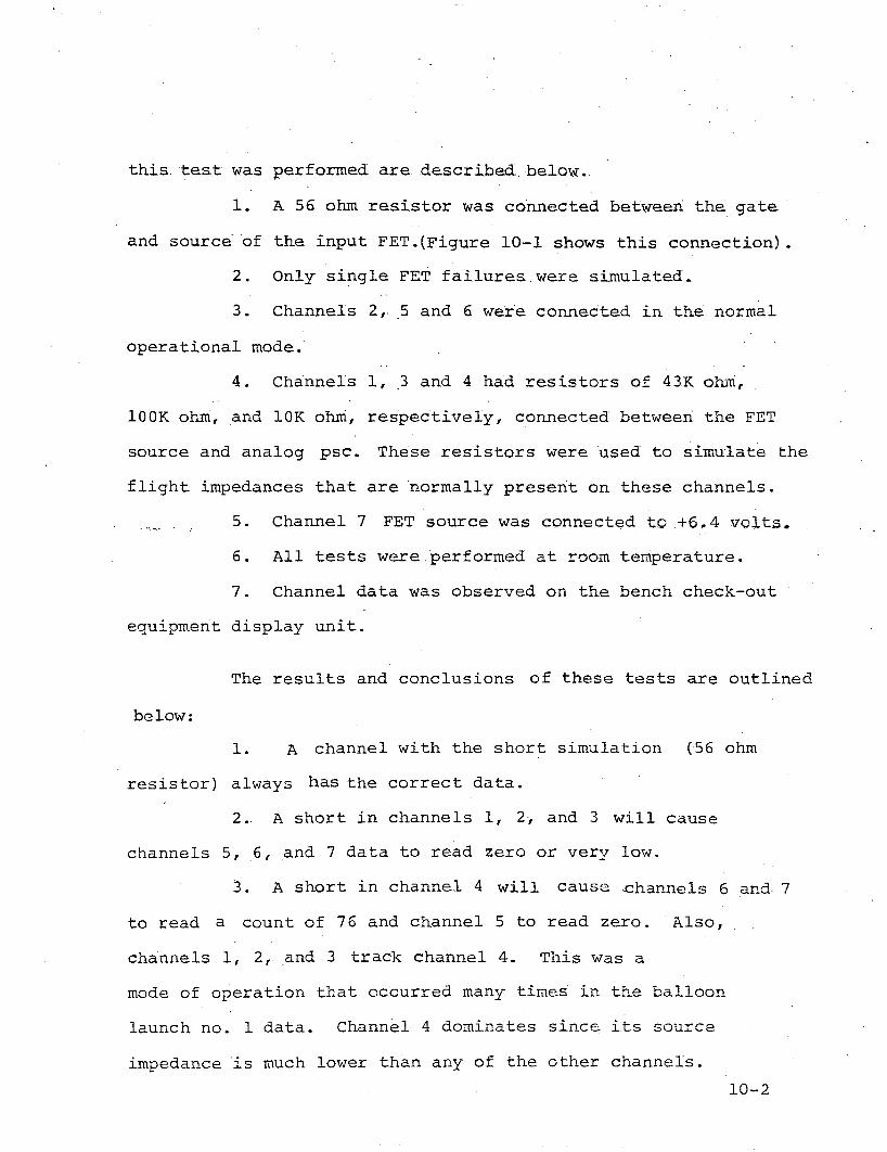
this test was performed are described. below.
1. A 56 ohm resistor was connected between the gate·
and source of the input FET.(Figure 10-1 shows this connection).
2. Only single FET failures were simulated~
3. Channels 2,. 5 and 6 were connected in the normal
operational mode;
4. Channels 1, 3 and 4 had resistors of 43K ohIn,
lOOK ohIri, and 10K ohni, respectively, connected between the FET
source and analog psc. These resistors were used to simulate the
flight impedances that are normally present on these channels.
5. Channel 7 FET source was connected to +6.4 volts.
6. All tests were performed at ~oom temperature.
7. Channel data was observed on the bench check-out
equipment display unit.
The results and conclusions of these tests are outlined
below:
1. A channel with the short simulation (56 ohm
resistor) always has the correct data.
2.. A short in channels 1, 2, and 3 will cause
channels 5, 6, and 7 data to read zero or very low.
3. A short in channel 4 will cause -channels 6 and 7
to read a count of 76 and channel 5 to read zero. . Also,
channels 1, 2, and 3 track channel 4. This was a
mode of operation that occurred many times in the balloon
launch no. 1 data. Channel 4 dominates since its source
impedance is much lower than any of the other channels.
10-2

Us:ing the. equivalent circui.t of each ch.a:nnel and the
superposition theorem, close: correlation was obtained between
calculations and thee.xperimental results described above for
a one channel FET failure.. Multiple ·channel FET failures,
however, made calculations more difficult since the source
impedance connected to eachFET varies considerably during normal
.operation. A computer program, where the source impedances could
be varied in increments would have been necessary to complete
the calculations in a reasonable time period. Additional
calculations, hOwe.ver,were not necessary since the failure mode
had been isolated to channel FET shorts.
10.2 Balloon Launch Series No.2
For the second series of balloon launches (Oct - Nov
1970), some modifications of the·BlP system were made to reduce
the effects of this suspected phenomena. Namely, channel 4
balloon over-pressure, which had over 90 feet of wire between
the sensor and the BlP was removed from ten of the fourteen systems
that were launched. For these ten BlP systems, three different
types of internal channel 4 BlP connections were used. Three BlP
systems had. channel. 4 connected to +4.8 volt "e" power. Channel 4
was terminated in 10K ohm for two other BlP systems. Five BlF
systems had challi~el 4 open.
10-3

The remaining four BIP systems that were launched in
October and November 1970 employed two relays in parallel that
would operate only when +12 volt nC" power was energized. Figure
10-2 shows the schematic of the electrical circuit and connections.
Telemetry channels 1, 3 and 4 .were connected to the external
sensors,thr'oughthe relay contacts., only during the satellite
interrogations, thus minimizing the probability of BIP damage.
The resistor and zener diode were ·placed in the circuit to
p~event damage if a high voltage spike occurred at thetirne
when the relay was energized.
These precautions for Balloon Launch No. 2 significantly
reduced the loss of external telemetry sensor information as
evidenced by the comparison between Table 8-1 and Table 9-1.
Coincidentally, the two BIP's that experienced a loss of
telemetry information were recovered. PIS, recovered at Lumblli~ashi,
Congo, Africa, was returned to GI/ESD and analyzed, the results of
which are detailed in Section 10.3. The second recovered EIP,
POI, has not been returned and analyzed to date. POI, which had
the relay modifications, experienced a complete loss of telemetry
information over South America a few days after a launch during
a storm.
10-4

10.3 P15, BIP Recovered from Africa
BIF 'p15,.launched from Ascension Island onOctobe.r
21st, 1970, .floated in a westerly direction over South America
and the 'Soutn Pacific Ocean. On November 2nd, 1970 the
telemetry data readout indicated that an external telemetry
sensor loss had occurred.. The balloon position at this time
was New Guinea. Channels 3 'and 4 had reduced pcm count data,
channels 5, 6, and 7 were reading zero, and channel 1 appeared
to have the correct reading. From the simulation test program
data described in section 10.1,it appeared that a channell
failure had occurred. Using source impedances calculated
from previous. good data, the equivalent circuit,'and the
superposition theorem, a good correlation was made between the
actual and. calculated data. The results of these calculations
for day 11/2/70 orbit 2794 are tabulated below.
Channel ActuaT .(Volts ) Calculated .(Volts)
2 3.225 3.332
J 3.825 4.04
4 4.625 4.639
The details of these calculations are shown in Appendix I of this
report. Data from subsequent 'orbits did not correlate. This appeared
to indicate that another channel FET failure had occurred. Calcula
tions of multiple channel failures were not attempted because of
their tedious 1 time-consuming nature. It was proposed that a
computer program be written to perform these calculations, but at
this time it was believed not to be warranted.
10-5

The balloon system of PIS failed over Africa and
was recovered at Lurnburnbashi, Congo, Africa. Figures 10-3
and 10-4 are photographs, .. taken after the African recovery,
of the electronics unit and the solar panel, respectively,
of PIS. The BIP was returned to General Instrument in
February of 1970. First, the system was checked for possible
damage, then connected to the BCE (Bench Check-out Equipment)
where the telemetry sensor data loss mode was verified. The
channel PET's were then checked with an ohmmeter and chennel
land 3 were found to have gate-to-source and gate-to-drain
shorts. These two FET's were replaced and normal operation
was verified on the BCE display.
Subsequent visual analysis of the damaged FET's,
under a microscope, showed black spots at the shorted
junctions. Discussions with Motorola, Inc., indicated that
this failure was due to a high voltage, low current transient.
Since the header had not arced over, Motorola felt that the
voltage was less than 600 or 700 volts. A high voltage~ high
current transient would have, obviously, destroyed the chip.
10-6

!tNA-LoG
~fM1PL.E'
INPUt
S;-GD..S/MULA,t:D
SHoRT
To Ro"vVDRIVe-R
-r-o O'itl€"lZ, ......... ----1
FE. G-AiES
\N Rov\{
G FtTE"
TO ALLFE! D~AIN$
".,,' .'
,0 OT.\;-E"{?.... ~._----------...---------~ TO COL UMN
FEI""G ~TE'.5 DR./ VcR.
\ NC.DI..UMN
-,-/2V(IN)
FlG.IO-\ FEI10-7

CH
AN
'IN
PC
.HA
NI
CH
AN
"3TO
MU
XlN
PA
CH
AN
?>C.~#\N
4TO
MU
XIN
PC~At-J
4T
OM
UX
7-
K2
174
sY+
12.V
(c.)
7·
~~'~
(T3K
1"-
9R
\R2
..R
3
_Lp
sc..
.>J_
l2.
7K
17le
i-
.01
IC.3
~
.01
-C
R3
r'i!
--
--
-C
.RS
IN30
2.S
,;.~
.,
4IN
30
2S
0--
29
AN
AL
P5C
.
~-, o ! 'X)


10-10

11.0 REAL TIME TWO SECOND TIMER
The two second timer located on printed circuit board
A2A3 is not a real time indicator, but measures the interval of
timewheri "c" pow-er is on, when the BIP system is operating
normally. Thus, in order to prec.1udea potential system
catastrophic failure, namely, .a system malfunction where l1C"
power remains on; a real time two second timer (A2AIO) was designed
and incorporated into the BIP system. Figure II-lis the logic
schematic of A2AIO. A photograph of the assembled printed circuit
board is shown in Figure 11-2.U1 is biased in the off state (0 volts output) when
power is applied to the circuit. This signal is applied to U2
causing pin 11 of U2 to a logic "1", enabling the end of two
second (old) to be gated through U2 pin 6 as the end of 2 second
(new) signal. This signal turns off all power except stand-by
power. When this end of two seconds (old) signal is not
generated~ the time constant of Rl and CI will enable pin 2 of
Ul to exceed the voltage at pin 3 of Ul, causing a positive
transition (logic "1") at pin 6 of Ul. This signal will now be
gated through U2 to become the end of 2 second (new) signal. Thus,
the maximum amount of time for "c" power to be on will be limited
under all conditions.
11-1
'j"

-----1
I I I I I
CD
22
01
I-----~
RZ-1
1'1
(C)0
,...
----
----
'\/\
I'v-
41
0..
fLY4
vJ
c.1<
.\t
e:,o/.
,o.jl
S'".
>A.
~\
+I2
."(C
)c.,
,)--
--<
Il--
i\,l
\,I\
r---
Ml-
----
-f>
..l
1.1K
(I
'1~w
.I.2
lOu~
lJI
~>r----_>------1-4
t';o
,o-
IOw
vD<:
.M
C.11
10(F
."
-3
5~4.eV(C)
CD
PSC.(~
R.D)0>
------
------
-.1....'
EN
DC
lFQ
)----:-
.l
2~EC.
TIM
£.R
,(O
LD
)
EN
DU
I:4r--------------------------------------~
2sE
,CT
IM.I
<.
(NE
w)
R3
M)'
.C
...A
.Nr
(j)
------A
/V
\r-----.
lOO
K.
!oj"
!.li
S'o
k)
FIC
,UR
.EII~
1-
TWO
SE
Co
ND
TIM
f:.R
SC
HE
MA
TIc
.D
IAb
RA
M-A
2A
IO.
f-'
I-' I N

-
-
•
C'I
t..r..

APpENDIX I
Calculation of PIS Channels 2, 3 'and 4 Volt~ges for Day
11/2/70, Orbit 2794.,
I,. Calculate Thevenin Equivalent for Channels 2
through 4 when operation is normal. 'Data from Orbit 2781 will
be used since Orbit 2794 was a noon time interrogation •.... ...... . .... " ,
, Channel PCM Count ' Vo'lta'ge
1 73' 3.675
2 70 3.525
3 127 >6.375
4 107 5.375
5 109 5.475
6 109 5.475
7 81 4.075
Channel 2+8. 9V
3.525 = 8.29x57.6RT 2+57.6
~2 = 77.8K ohms
= +3.525V
+3.,525V
57.6K
R.rhev2
=
VThev2
77.8+57.677.8x57.6 = 33.lK ohms
, Channel 3+8. 9V
lOOK
>6.375V
Assume RT3
open
since Channel 3 hasconsistently read 127.
R '= lOOK ohrnsThev3
v = +8. 29VThev3
A-I

Channel 4 This Channel was connectedto +4. 8V. "CII -power through·a 10K resistor, therefore,
R.rhev4= 10K ohms
v - +5.375VThev4 -
2. If a Channell failure is assumed, then Channell
RT I = 38.8K ohms
42.2K
R.rhevl
= = 20.2K ohms42.2x3B.8
42.2+38.8
.. 8.29.··R'ti=
42.2+RT I
3.975
+3.975
is reading correctly.
+8. 9V
= +3.975V
3. Calculation of Channel 2 voltage for a Channell
failure.
Equivalent Circuit:
20.2K
A-2
220K
T-13.25
R36 220K
R13
33.1K1+3.975 --- +3. 525-=-
l~r_1CH. 1 CH. 2

Using the Superposition Theorem.
3' .525x (2'0 . 2x44Q) / (20.2+440)V2 = 33.l+(20.2x4401/C20. 2+440] = +1.30V
=-13'•25x' (20: . 2x3 3 .'1) I (20'. '2'+33.1 ) =V 3 440+C20.2x33.1}/(20.2+33.l1'
v = 2.40 + 1.30 - 0.368 = 3;332V
-0.368V
4. Calculation of Ch~nne13voltagefora Channell
failure.
Equivalent Circuit: .
20.2K
R13
lOOK
R36
+8.29
l_I_J
220K
220K
-13.25
CH. 1 CH. 3
A-3

Uaing the Superposition Theorem.
3' • 975x CI0 Ox440} / (10'0+4"40 )VI =20 •.2+ ClOOx440} / (100+44Q) =
=8·.29X (20.·2x440·1 / (2'0 .2+4"401 =V2 loO+C20.2x4401j(2Q.2+440l
+3.19V
+1.34V
_· ....13·.25x C20·.2xl001/ C20·.2+100} =V3 - 440+C20.2xI0017C20.2+100J -O.487V
v = 3~19+ 1~34 - 0.487'= 4.04V
5. Calculation of Channel 4 voltage 'for a Channell
failure".-
Equivalent Circuit:
20.2K
R13
10KR36
220K
220K
+3. 97fiV-=- 5.37SV - -13. 25V
l_I~CH. 4
A-4

Usi.ng the Superpos.ition Theorem.
,-" "3" • 97S"x (l"OX44 0"1/ (10+4"40)" VI" ~20. 2+ (10x4401/ (10+440) = +1.297V "
= 5".375x (20 .2x440) "/ (20 .2+4401 =V2 10+(20.2x440}/C20.2+440)
_" "-13".25x" (20· ~2XHJ'/·C20 .2+1"0) =V3 - 440+(20.2x101/C20.2+10)
v = 1.297 + 3";54 - D.198 = 4.639V
3.54V
-0.198V
A-5

APPENDIX II - SPECIFICATION 121765
1.0 ELECTRICAL PERFORMANCE TEST
verifies operations of all BIP functions at room
temperature. Each of the tests are briefly described in the
following sections.
1.1 Address and Address Recognition Test
Verifies that the BIP will recognize its own address
and will not respond to l6-bit address code transmissions differ
ing by one or more bits from its hard-wired address.
1.2 Correct Frame Generation Test
Verifies that the BIP, upon interrogation, will trans
mit a frame consisting of two address complements followed by 7
lines of data followed by one address complement. (3~ of the 7
lines are unused).
1.3 Coder Accuracy Test
Verifies that the BIP analog-to-digital converter will
convert analog input data in the range to zero to +6.4v to corres
ponding 7-bit binary words with an error ±70 millivolts or less.
AA-l~

1.4 Multiplexer and Coder Input Impedance Test
Verifies that the operation of the BIP multiplexer is
correct by demonstrating the one-to-one correspondence between
analog inputs and digital data word locations in the format. It
also verifies that the BIP input impedance at each analog input is
greater than lOOK ohms during the encoding time for that input.
1.5 TransrnitterCarrier Frequency and Output Power Test
verifies that the BIP transmitter carrier frequency
and output power are correct and within tolerance.
1.6 Transmitter Turn-On!Turn-Off Verification
ver.ifies that BIP is turned off by the End of Frame
signal.
1.7 Transmitter Turn-Off Redundancy Test
Verifies that the redundant 2-second clock turn-off
signal generated will turn off the transmitter a maximum of 2
seconds after it has been turned on in the event that an end of
frame pulse does not occur.
1.8 Transmitter Modulation Test
verifies that the transmitter is properly modulated by
the 12.5 kHz· dat.a.
AA-2

1.9 Address Recognition Test
Verifies that the BIP will recognize its address within
100millisecohds 9~/o of the time.
1.10 12.5 KB Bit Error Rate Test
Verifies that the 12.5 KB/sec error rate will be less
than 62.5/sec at a signal level of -112 dbm.
1.11 1 KB Bit Error Rate Test
Verifies that the 1.0417KB/sec error rate will be less
-5 . 1than 10 at a s~gnal leve of -112 dbm.
1.12 Input Voltage Variation Test
Verifies that the BIP will operate as required over
specified input voltage excursions.
1.13 Sensor Output Verification Test
verifies that the user outputs supplied by the BIP are
as required.
1.14 BIF Delay Measurement Test
Determines the delay through the platform system, using
the ranging feature of the satellite.
AA-3

2.0 Qualification Test
This test is designed to simulate the altitude tempera~
ture environment that BIP packages are exposed to in actual flight.
Figure 2-1 illustrates the test conditions.
o Transmitter RF power output and frequency
o The complete data frame is viewed on a storage
oscilloscope to ensure correct address, address
complement, data, and parity.
At the conclusion of the qualification test the BIP
package is brought back to room temperature and to ensure no
degradation a complete electrical performance test is retaken.
AA-4

~'
....
(~II~~:.)
EXPO
SUR
E55
,000
FT(
WIN
TER
)D
AY
EXPO
SUR
E5
5,0
00
FT
.__.__(SU~~R
)EX
POSU
RE
.80
,000
FT.
ROO
MA
MB
IEN
T
~ f • 1 • 1 , a n !' n ,. • • • ) i 1
oP
l(t'
;.S~FACE
~65
C---'-----------
®-:-
ABBR
EVIA
TED
ELEC
TRIC
ALPE
RFO
RM
AN
CE
TEST
o....
STAR
TTI
MES
~}-
CHA
MBE
RTR
AN
ISTI
ON
TIM
ES
©-S
IPD
ElA
YM
EASU
REM
ENT
TEST
rIG
.-.Z
·-1
...