llc installation instructions: euro models 1770, 1771 ... · in other pedal operated devices all...
TRANSCRIPT
OPERATION
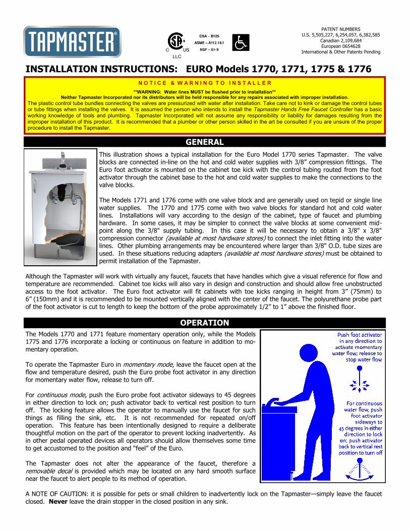
This illustration shows a typical installation for the Euro Model 1770 series Tapmaster. The valve blocks are connected in-line on the hot and cold water supplies with 3/8” compression fittings. The
Euro foot activator is mounted on the cabinet toe kick with the control tubing routed from the foot activator through the cabinet base to the hot and cold water supplies to make the connections to the
valve blocks.
The Models 1771 and 1776 come with one valve block and are generally used on tepid or single line
water supplies. The 1770 and 1775 come with two valve blocks for standard hot and cold water lines. Installations will vary according to the design of the cabinet, type of faucet and plumbing
hardware. In some cases, it may be simpler to connect the valve blocks at some convenient mid-point along the 3/8" supply tubing. In this case it will be necessary to obtain a 3/8" x 3/8"
compression connector (available at most hardware stores) to connect the inlet fitting into the water lines. Other plumbing arrangements may be encountered where larger than 3/8" O.D. tube sizes are
used. In these situations reducing adapters (available at most hardware stores) must be obtained to permit installation of the Tapmaster.
Although the Tapmaster will work with virtually any faucet, faucets that have handles which give a visual reference for flow and temperature are recommended. Cabinet toe kicks will also vary in design and construction and should allow free unobstructed
access to the foot activator. The Euro foot activator will fit cabinets with toe kicks ranging in height from 3” (75mm) to 6” (150mm) and it is recommended to be mounted vertically aligned with the center of the faucet. The polyurethane probe part
of the foot activator is cut to length to keep the bottom of the probe approximately 1/2” to 1” above the finished floor.
GENERAL
The Models 1770 and 1771 feature momentary operation only, while the Models 1775 and 1776 incorporate a locking or continuous on feature in addition to mo-
mentary operation.
To operate the Tapmaster Euro in momentary mode, leave the faucet open at the flow and temperature desired, push the Euro probe foot activator in any direction
for momentary water flow, release to turn off.
For continuous mode, push the Euro probe foot activator sideways to 45 degrees
in either direction to lock on; push activator back to vertical rest position to turn off. The locking feature allows the operator to manually use the faucet for such
things as filling the sink, etc. It is not recommended for repeated on/off operation. This feature has been intentionally designed to require a deliberate
thoughtful motion on the part of the operator to prevent locking inadvertently. As in other pedal operated devices all operators should allow themselves some time
to get accustomed to the position and “feel” of the Euro.
The Tapmaster does not alter the appearance of the faucet, therefore a
removable decal is provided which may be located on any hard smooth surface near the faucet to alert people to its method of operation.
A NOTE OF CAUTION: it is possible for pets or small children to inadvertently lock on the Tapmaster—simply leave the faucet
closed. Never leave the drain stopper in the closed position in any sink.
INSTALLATION INSTRUCTIONS: EURO Models 1770, 1771, 1775 & 1776
PATENT NUMBERS U.S. 5,505,227, 6,254,057, 6,382,585
Canadian 2,109,684 European 0654628
International & Other Patents Pending LLC
N O T I C E & W A R N I N G T O I N S T A L L E R
**WARNING: Water lines MUST be flushed prior to installation** Neither Tapmaster Incorporated nor its distributors will be held responsible for any repairs associated with improper installation.
The plastic control tube bundles connecting the valves are pressurized with water after installation. Take care not to kink or damage the control tubes or tube fittings when installing the valves. It is assumed the person who intends to install the Tapmaster Hands Free Faucet Controller has a basic working knowledge of tools and plumbing. Tapmaster Incorporated will not assume any responsibility or liability for damages resulting from the improper installation of this product. It is recommended that a plumber or other person skilled in the art be consulted if you are unsure of the proper procedure to install the Tapmaster.

STEP #1 - Hook up the control tubing from the Euro foot activator to the valve block with the plastic sleeves provided as per Figure 5. (Note: To fa-cilitate the installation of the tubing and sleeves, dip the ends of the tubing into hot soapy water and, using a pair of needle nose pliers, push the tubing on to the barb fittings. An adjustable wrench opened to the diameter of the tubing will assist in pushing on the sleeves. Take care not to damage the barb fittings or crush the tubes). If a tube must be removed from a barb fitting,
split the tube along its length with a sharp knife (Do not pull as this may damage the barb).
GENERAL: The instructions below for mounting the Euro probe are for a typical installation and only a guideline. Sink/cabinet styles, toe kick heights and con-struction materials vary greatly. If mounting onto a metal cabinet base the wood mounting screws should be replaced with machine screws with nuts and wash-ers. Be sure to take into account the swing of the locking version of the probe (as illustrated on the next page) placement of mats, typical users etc. STEP #1 - As in Figure 1 draw a line on the cabinet toe kick vertically aligned with the center of the faucet/sink. (NOTE: this is recommended for both right and the left footed users — not a requirement). Draw a horizontal line approxi-mately 3/4” (19 mm) below the toe kick overhang (be sure the cabinet door will clear the Euro housing and that this line is level). STEP #2 - Attach the
self-adhesive drilling template label provided to the toe kick by align-ing the crosshairs on the template with the vertical and horizontal line on the toe kick. Drill two pilot holes for #6 screws and drill a 3/8" to 5/8" hole for the control tube bundle as indicated on the template. Drill
another hole of similar size in the back of the inside of the cabinet floor. Remove the template.
STEP #3 - Route the control tube bundle through the Euro housing
and use a "fish tape", stiff wire (example: coathanger) or other means to pull the control tubing through the holes (see the illustration on page 1). Be sure not to kink the tube bundle. With the two #6 x 1-
1/4" long screws provided mount the Euro hous-ing.
STEP #4 - As in Figure 2 position the actuator and pilot valve simultane-ously into the housing. Be sure the black plastic part of the actuator is vertically aligned with the brass button of the valve. Install the cap and tighten the set screws in the housing with the 5/64" hex wrench provided.
STEP #5 - As in Figure 3 place a mark on the probe so its cut length will position its rounded end approximately 1/2 to 1" above the finished floor (NOTE: height of the probe above the finished floor is a personal prefer-ence - 1" clearance is recommended for situations where users are in shoes and to facilitate cleaning, whereas, the lower 1/2" clearance is rec-ommended for situations where us-ers are in bare or stocking feet).
STEP #6 - As in Figure 4 use a sharp knife and piece of paper rolled on the probe as a guide to make as square a cut as possible. Push the probe on to the stepped barb of the actuator as far as possible and check for free 360°movement of the probe. On 1775 and 1776 models push the probe to the right and left locked positions (NOTE: the locking feature is designed for use by the foot and using the hand will seem difficult– this is normal)
INSTALLING THE VALVE BLOCKS
INSTALLING THE EURO PROBE
Figure 5 -2-
Figure 2
PILOT VALVE
ACTUATOR
CAP
ROLLED PAPER
Figure 4
PROBE
Figure 1 TUBE BUNDLE
HOUSING
#6 x 1-1/4 SCREWS (2)
Figure 3
0.5 to 1.0 in. (12 to 25mm) ABOVE FLOOR
CUT LINE
-3-
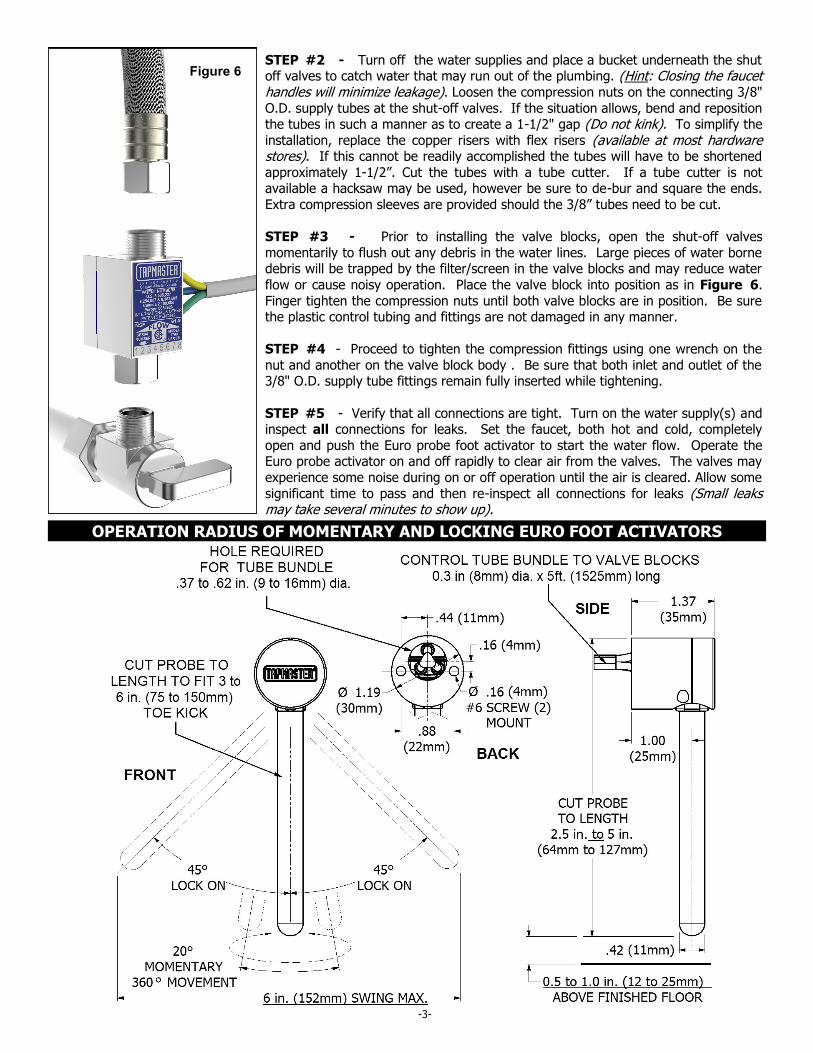
STEP #2 - Turn off the water supplies and place a bucket underneath the shut off valves to catch water that may run out of the plumbing. (Hint: Closing the faucet handles will minimize leakage). Loosen the compression nuts on the connecting 3/8"
O.D. supply tubes at the shut-off valves. If the situation allows, bend and reposition the tubes in such a manner as to create a 1-1/2" gap (Do not kink). To simplify the
installation, replace the copper risers with flex risers (available at most hardware stores). If this cannot be readily accomplished the tubes will have to be shortened
approximately 1-1/2”. Cut the tubes with a tube cutter. If a tube cutter is not available a hacksaw may be used, however be sure to de-bur and square the ends.
Extra compression sleeves are provided should the 3/8” tubes need to be cut.
STEP #3 - Prior to installing the valve blocks, open the shut-off valves
momentarily to flush out any debris in the water lines. Large pieces of water borne debris will be trapped by the filter/screen in the valve blocks and may reduce water
flow or cause noisy operation. Place the valve block into position as in Figure 6.
Finger tighten the compression nuts until both valve blocks are in position. Be sure the plastic control tubing and fittings are not damaged in any manner.
STEP #4 - Proceed to tighten the compression fittings using one wrench on the
nut and another on the valve block body . Be sure that both inlet and outlet of the 3/8" O.D. supply tube fittings remain fully inserted while tightening.
STEP #5 - Verify that all connections are tight. Turn on the water supply(s) and inspect all connections for leaks. Set the faucet, both hot and cold, completely
open and push the Euro probe foot activator to start the water flow. Operate the Euro probe activator on and off rapidly to clear air from the valves. The valves may
experience some noise during on or off operation until the air is cleared. Allow some
significant time to pass and then re-inspect all connections for leaks (Small leaks may take several minutes to show up).
Figure 6
OPERATION RADIUS OF MOMENTARY AND LOCKING EURO FOOT ACTIVATORS

Rev. 2.0
-4-
PH: 800-791-8117 FAX: 403-275-5928
Web: www.tapmaster.ca E-mail: [email protected]
Tapmaster Incorporated 20175 Township Rd 262 Calgary, AB Canada T3P 1A3
TROUBLE SHOOTING
FIVE YEAR LIMITED WARRANTY
Congratulations on your purchase of a TAPMASTER Hands Free Faucet Controller.
TAPMASTER products are thoroughly tested before shipment and are warranted to be free of defects in material and
workmanship for five years from the date of original purchase. The sole obligation of Tapmaster Incorporated under the warranty is to provide replacement parts or at its option to repair the defective product or to provide the
replacement product. Replacement parts furnished in fulfillment of this warranty are warranted only for the unused portion of the original warranty. Labor and shipping charges are not included.
Warranty conditions - The five year warranty is subject to exclusions and limitations as stated below:
Warranty extends only to defects which occur during normal use and intended applications and does not extend to damage to products or parts resulting from alteration, repair, modification or faulty installation. This warranty does
not cover damage resulting from water borne debris or from media other than clean potable water. Tapmaster Incorporated makes no other express warranty on this product, all implied warranties including any implied warranty
of merchantability and fitness for a particular purpose are hereby disclaimed and excluded. In no event shall
Tapmaster Incorporated be liable for special, incidental or consequential damages resulting from the use of this product or arising from breach of warranty or contract, negligence, loss of time, inconvenience or loss of use of
equipment.
Symptom Possible Cause Remedy
The hot or cold water Pinched tubing Check control tubing
is very slow to turn on (yellow and blue) or will not turn on
The hot or cold water Pinched tubing Check control tubing
is very slow to shutoff (green and blue) or will not shutoff
Noise from the Valve Blocks The Valve Block may have Service the Valve Blocks while the water is running excessive debris trapped under
its Filter-screen
Noise from the Valve Blocks Air in the system Operate the pedal on and off
when turning water on and off rapidly to clear air from the valves.
Further information: www.tapmaster.ca or call 800-791-8117