llooookk44mmyybbooddyy - core · llooookk44mmyybbooddyy remote physical exercise monitorization ......
TRANSCRIPT

75
LLooookk44MMyyBBooddyy
Remote Physical Exercise Monitorization
Firmware Module
Dissertation presented to the University of Coimbra to complete the
necessary requirements to obtain the Master‟s degree in Biomedical
Engineering
2009
Andreia Melo Carreiro
Master of Biomedical Engineering
Faculdade de Ciências e
Tecnologias da
Universidade de Coimbra

Look4MyBody
2
Departamento de Física
Faculdade de Ciências e Tecnologia
Universidade de Coimbra
LLooookk44MMyyBBooddyy
Remote Physical Exercise Monitorization
Firmware Module
Name: Andreia Melo Carreiro
Student Number: 2004107096
Project Coordinator: Professor Carlos Correia
Technical Supervisor: Engineer Soraia Rocha
Dissertation presented to the University of Coimbra
to complete the necessary requirements to obtain
the Master‟s degree in Biomedical Engineering
Coimbra, September 2009

Look4MyBody
3

Look4MyBody
ii
Abstract
The project was carried out based on the new concept of gym circuit, which
provides quick training for women, with hydraulic machinery.
This type of training is directed exclusively for women since the environment is
similar to a group class, and it is not as intimidator as traditional gyms. The training is
essentially Cardiovascular, and are used stimulate and increase the resistance of the
clients. This is not suitable for men, because the carried out training does not allow
increasing the muscle mass.
The Look4MyBody system is a prototype whose function is to provide a
physical exercise monitorization in the gymnasiums which adopts the concept of
physical exercise in a circuit program, in order to allow women that attend those places,
a real-time exercise monitorization and also access to the reports that evaluate their
promoting important feedback results.
The system is composed by a reed-switch, which allows the verification of the
distance travelled by the client. These data is acquired in a concentrator module located
near the machine.
The data is transmitted remotely to a terminal module, where it's sampled in
real-time and stored in order to allow the preparation of reports.
The communication technology used and imposed by ISA was RF, since the
Socket Radio 868 MHz and the Dongle Radio USB 868 MHz provided communicate
via RF.
Throughout the development of this document, the project requisites will be
analyzed. The system description includes all specifications and the module
concentrator‟s firmware elaboration.
The performed testes on the end of the project, allow to obtain results which
indicate that the developed system executes correctly the required functions.

Look4MyBody
iii
Resumo
O projecto foi realizado com base no novo conceito de ginásio em circuito, que
proporcionam treinos rápidos para mulheres, com máquinas hidráulicas.
Este tipo de treino é direccionado exclusivamente para mulheres na medida em
que o ambiente é similar a uma aula de grupo, e não é intimidativo como os ginásios
tradicionais. Os treinos são essencialmente cardiovasculares, servem para tonificar e
aumentar a resistência das clientes. Não são adequados para homens, pois o treino
realizado não permite o aumento de massa muscular.
O sistema Look4MyBody é um protótipo de um sistema cuja função é
proporcionar uma monitorização do exercício físico, nos ginásios que adoptam o
conceito da prática do exercício físico em circuito, de modo a permitir às mulheres que
frequentam esses ginásios terem a monitorização do exercício realizado em tempo real e
também terem acesso a relatórios para avaliar a sua performance.
O sistema é constituído por reed switchs, que permitem verificar a distância que
foi percorrida pela cliente, estes dados são adquiridos num módulo concentrador
localizado nas imediações.
Os dados são depois transmitidos remotamente para um módulo terminal onde
são amostrados em tempo real e são armazenados de forma a permitir a elaboração de
relatórios.
A tecnologia de comunicação utilizada for RF pois foi a imposta pela ISA, uma
vez que, o Socket Rádio 868 MHz e a Dongle Rádio USB 868 MHz providenciadas
comunicam por RF.
No decurso desta tese vão ser analisados os requisitos do projecto. A descrição
do sistema inclui toda a especificação e a elaboração do Firmware do módulo
concentrador.
Alguns testes realizados na parte final do projecto permitiram obter resultados
que indicam que o sistema desenvolvido realiza correctamente às funções exigidas.

Look4MyBody
iv
Acknowledgments
First of all, I would like to thank the coordinators of this project, the Professors
Carlos Correia and José Basílio Simões for making the elaboration of this project
possible. I'm also Grateful to ISA, the entity that took me in during the elaboration of
my thesis.
I also would like to express my gratitude to Engineer Soraia Rocha due to her
help, orientation, coordination and presence at ISA, since it was of great value to me
and a solution to many of my problems. To her I express my deep appreciation and
congratulations on the work she has done.
I also would like to thank Engineer Paulo Santos, Engineer José Luís Malaquias
and Engineer Catarina Pereira, that although they all have very busy agendas, they
always found time to help me. Thank you for your kindness, your help, and the
orientation that you provided me on this final stage of my thesis.
I also would like to thank Engineer Miguel Aragão, Tiago Marçal, Pedro Pinto
and Nuno Esteves for the patience and attention they showed me throughout the year
and for all their help, as well as everything that they taught me which was fundamental
for the elaboration of this project. Thank you very much!
I also would like to express my gratitude to all the ISA employees for their
support, kindness and collaboration during my curricular internship.
I'm very thankful to all my friends and Bruno because they were “step one” on
this project. They were always my biggest support during the more difficult hours and
were also there to share my victories. I hold a special place in my heart for each and
every one of them.
Finally, I want to thank my family who, although were faraway, I always felt
them close to me, by showing me support and believing in me. With no intention to
devaluate any of them, I want to specially thank my father, José Manuel Sousa Carreiro,
because he is my role-model and idol. I dedicate this thesis to him because he is who I
owe the person I am today.

Look4MyBody
v
CONTENTS
ABSTRACT..................................................................................................................... ii
RESUMO.........................................................................................................................iii
ACKNOWLEDGMENTS............................................................................................... iv
CONTENTS .....................................................................................................................v
LIST OF FIGURES.........................................................................................................vii
LIST OF TABLES...........................................................................................................x
ACRONYMS AND DEFINITIONS............................................................................. .xi
1. Introduction.................................................................................................................. 1
1.1. Motivation...................................................................................................... 1
1.2. Objectives...................................................................................................... 3
1.3. Scopes……………………………………………………………………….3
1.4. Audience…………………………………………………………………….3
1.5. Document Structure....................................................................................... 4
2. Project Management..................................................................................................... 6
2.1. Project Members............................................................................................ 6
2.2. Tasks Division............................................................................................... 7
2.3. Project Supervising........................................................................................ 7
2.3.1. Supervising at ISA ......................................................................... 7
2.3.2. Supervising at CEI.......................................................................... 8
2.4. Project Planning…......................................................................................... 9
3. Related Works………………………………………………………………………12
3.1. Sensor Related……………………………………………… ……………12

Look4MyBody
vi
3.2. State-of-the-art……………………………………………………………..14
4. Project Requirements……………………………………………………………….. 15
4.1 Reed Switch…………………………………………………………..…….16
4.2. iButton……………………………………………………………………..19
4.2.1. iButton DS1990A………………………………..……….………19
4.2.2. Reader DS1992………………………………….……………….22
4.2.3. Chip DS2480B…………………………………….……………..24
5. System Architecture ………………………………………………………………...29
5.1. Physical Architecture ……………………………………….……………..29
5.2. Logical Architecture..............................................................................…...31
6. System Development Tools …………………………………………………………33
6.1. Compiler …………………………………………………………………..34
6.2. Programmer/Debugger …………………………………………………….35
6.3. Integrated Development Environment …………………………………….35
6.4. Acquisition and Transmission Module ……………………….……….…..38
6.4.1. Description of the Hardware …………………………………… 39
6.5. Socket Radio 868 MHz…………………………………………………….40
6.5.1. Bridge UART 24F ……………………………………………….42
6.6. Dongle Radio USB 868 MHz ……………………………………………..43
6.6.1. Bridge UART Dongle Radio USB 868 MHz……………………45
7. Firmware Design…………………………………………………………………….46
7.1. Firmware Description ……………………………………………………. 47
7.2. General Identification process of the iButton …………………………… 50

Look4MyBody
vii
7.2.1. How to detect the presence of the DS2480B…………………… 51
7.2.2. How to Reset the DS2480B……………………………………...52
7.2.3. .How to search the ROM number from iButton…………………53
7.2.3.1.. iButton Decoding ……………………………………………..54
7.3. Communication Technologies ……………………………………….…... 58
8. Conclusion………………………………………………………………………...…59
8.1. Future Works …………………………………………………………..… 60
8.2. Final Appreciation ………………………………………………………...61
8.3. Test and Results……………………………………………………………62
REFERENCES…………………………………………………………………………63
ATTACHMENT ……………………………………………………………………….66
A. Muscles worked in hydraulic machines circuit…………………………….66
B. Hardware test and Result…………………………………………………. ..70
B.1. iDemoboard and Socket Radio 868 MHz……………………..…..70
B.2. Dongle USB 868 MHz………………………………………….....72
B.3. Connector for expansion………………………………………..... 74
C. Hardware Schematics…………………………………………………..…..75
C.1. iDemoboard...............................................................................…...75
C.2. Socket Radio 868 MHz…………………………………………... 80
C.3. Dongle Radio USB 868 MHz………………………………..…… 82

Look4MyBody
viii
LIST OF FIGURES
Figure Legend Page
1.1. Circuit with different machines 1
3.1. Respiration Sensors 12
3.2. sEMG Active Sensors 12
3.3. ECG triode 13
3.4. Triaxial accelerometers 13
3.5. Force Sensors 13
3.6. CurveSmart 14
4.1. Architecture implemented in hydraulic machines 16
4.2. Reed Switch Components 17
4.3. Reed Switch Closed 17
4.4. Tape-measure and Reed Switch 18
4.5. iButton F5 Microcan TM
19
4.6. 64-bit unique ROM ‘Registration’ number 20
4.7. DS1990A Equivalent Circuit 20
4.8. BUS Master Circuit 21
4.9. Reader DS1990A 22
4.10. Standard Probe 22
4.11. DS2480B usage (simplified) 25
4.12. Outbound Search Data 28
5.1. Physical Architecture 29
5.2. Presentation of the monitorization exercises 30
5.3. Logical Architecture 31
6.1. Development Cycle 33
6.2. ICD 2 35
6.3. General Layout of the Board 38
6.4. Power 39
6.5. Radio Interface Module 39
6.6. Serial Radio 39
6.7. Devices that Communicate with the Socket Radio 40
6.8. Descriptions of the Socket Radio 868 MHz Connections 42

Look4MyBody
ix
6.9. Connecting to the type of the programming the ICD2 43
6.10. Devices that Connect Directly with Dongle USB 868 MHz 43
6.11. Connections of Dongle USB 868 45
7.1. The most used devices during the firmware development 47
7.2. Hydraulic Machine with measure tape which has four magnets
and a reed switch
47
7.3. A form with the counting pulses 48
7.4. Chart with the monitorization of the exercises 48
7.5. General Flowchart of the Firmware 49
7.6. Identification Process of iButton Flowchart 50
7.7. Detect the Presence of the DS2480B Flowchart 51
7.8. Reset to the DS2480B Flowchart 52
7.9. Extract ROM number and iButton Identification 53
7.10. Flowchart of iButton decoding 56
7.11. Block Diagram of the Decoding of the ROM number 57
7.12. Block Diagram Radio Communication 58
A.1. Biceps and Triceps 66
A.2. Leg extension and leg curl 66
A.3. Shoulder Press and Lat Pull 67
A.4. Leg Press 67
A.5. Abdominal and Back 68
A.6. Hip abductor and adductor 68
A.7. Chest and Back 69
A.8. Squat 69
B.9. Board Suport iDemoboard 70
B.10. Socket Radio 868 MHz 70
B.11. Socket TX and RX LED 70
B.12. Dongle Seen From Above 72
B.13. Dongle Seen from Bottom View 72

Look4MyBody
x
LIST OF TABLES
Table Description Page
2.1. Project Members 6
2.2. Tasks Assignment 7
2.3. Gant Diagram of the 1st semester 9
2.4. Gant Diagram of the 2nd
trimester 10
2.5. Gant Diagram of the 3nd trimester 11
3.1. Some disadvantages of the CurveSmart 14
4.1. Features of the Reed-Switch 17
4.2. Reed Switch Closed 17
4.3. Key Features of the DS9092 23
4.4. Features of the DS2480B 24
6.1. Applications of the Socket Radio 868 40
6.2. Features of the Socket Radio 868 41
6.3. Applications of the Dongle USB 868 43
6.4. Features of the Dongle USB 868 44
7.1. 16 bytes of the ROM number converted into bits 54
7.2. Decoding Table 56
B.1. Static Tests on Socket Radio 868 71
B.2. Dynamic Tests on Socket Radio 868 71
B.3. Static Tests on Dongle USB 72
B.4. Dynamic tests on Dongle USB 72

Look4MyBody
xi
ACRONYMS AND DEFINITIONS
Acronyms Definitions
bps Bit per second
CD Compact Disc
CEI Centro de Electrónica e Instrumentação
Cm Centimeters
CRC Cyclic Redundancy Check
C30 Compiler
ECG Electrocardiogram
EEPROM Electrically Erasable Programmable Read-Only Memory
EMG Electromyography
GHz Giga Hertz
ICD In-Circuit Debugger
ID Identification
IDE Integrated Development Environment
ISA Intelligent Sensing Anywhere
LED Light Emitting Diode
Look4MyBody Name of the project
LSB Least Significant Bit
MHz Mega Hertz
MSB Most Significant Bit
M2M Machine to Machine
OW Reset How Reset?
OW Search How Search?
OEM Original Equipment Manufacturer
PC Personal Computer
P2P Pear to Pear
PLL Phase-Locked Loop
R&D Research and Development
ROM Read Only Memory
Rx Receive
RS-232 Recommended Standard 232

Look4MyBody
xii
RS-485 Recommended Standard 485
RF Radio Frequency
SPI Serial Peripheral Interface
Tx Transmission
UART Universal Asynchronous Receiver/Transmitter
USB Universal Serial Bus
V Volt

75
CChhaapptteerr 11
11.. IInnttrroodduuccttiioonn
1.1 . Motivation
Some people, especially women, see the gym as intimidating. Many of these
infrastructures have only one personal trainer, incapable to attend and support the
individual need of each client.
Other disadvantages are the necessity to adjust the weights of each machine to
each person and the fact that they are typically manufactured for the male client.
These are the reasons that led to the creation of a new concept of a gym
conceived for women. This concept is based on the use of machines with hydraulic
resistances.
The user has access to complete aerobic and force strength training in only 30
minutes per session with the constant presence of a trainer. The exercises performed on
these machines are considered safe. The reason for this safety is because these machines
are adapted to people of all ages and physical conditions since it doesn‟t have any kind
of impact during the exercise. Like this there is no harm caused to the articulations,
making it a complete session exercise but without the risks of lesions injury and
muscular pain. [1]
Based on studies carried out on women, they have relied more on this type of
exercise because it's fast, lasting only 30 minutes and carried out in various circuits on 8
different machines.
FIGURE 1.1: Circuit with different machines [2]
1

Look4MyBody
2
This is considered a full training, because in just 30 minutes it can work multiple
muscles simultaneously, they are:
Biceps and triceps;
Quadriceps and hamstrings;
Trapezius, deltoid and latissimus dorsi;
Iliopsoas and gluteals;
Abdominal and erector spinae;
Adductor and tensor fasciae latae;
Pectoralis major, rhomboid and latissimus dorsi;
This feature is of great importance to the women of today due to their active and
demanding careers and not to mention the responsibility of a family to care for so they
are generally left with little time for the gym. They consider this an easy exercise
program because it offers the possibility to work all parts of the body and each person
can train within their physical condition being these some of the reasons they choose
this modality. [2]
Due to many women seeking this type of exercise program, our project was
elaborated in order to, whoever uses this type of exercise in gyms, have control or
knowledge of the calories they burn during it, the time they spend in each machine of
the circuit, the distance they achieve or even the reports so that they can see and
evaluate their own evolution throughout their training. Therefore, the idea for Remote
Monitoring of Vital Signs in a Gymnasium came up. [2]
This new concept has a system that monitors vital signs and gives women, in
general, safety, efficiency and effectiveness in a dynamic and comfortable environment.
[2]
A client may follow her own progression with the certain she's not exceeding her
own physical limitations. [2]

Look4MyBody
3
1.2 . Objectives
The main goal of this project is to develop a prototype system which is a base pilot
integration in a gym with eight hydraulic machines, monitoring the calories used during
physical activity.
Each machine in the gym will be associated with an acquisition board (where the
Socket Radio 868 MHz is) that receives the data of the physical exercise. This will send
the data via radio to a Dongle Radio USB 868 MHz that is connected to a server at the
gym. On this server are stored the calculated burnt calories during the exercise. This
information will be shown in real time on a screen visible to all clients using a Windows
application. At the end of each session, the client will have access to the data resulting
from the exercise session as well as their prior previous results. They can also watch
this information at home.
1.3. Scope
This project was developed in a master‟s degree in Biomedical Engineering
taught at the University of Coimbra in the academic period 2008/2009. It's the result of
a partnership between ISA - "Intelligent Sensing Anywhere" and CEI - "Electronic
Instrumentation Center".
1.4. Audience
This document is mainly addressed to the supervisors and juries assigned to this
project and to the academic circle around biomedical engineering, informatics, electrical
and related area.

Look4MyBody
4
1.4. Document Structure
This document is composed by eight chapters, which enlighten all the
development of the project Look4MyBody during the last year of Master Biomedical
Engineering.
Firstly, the Abstract elucidates the reader with a brief summary explaining the
content of this document.
Subsequently, are presented the acknowledgments and the thesis index.
Following the index, three tables are displayed. The first one corresponds to the
figures table, the second one is the tables list and thirdly, a table with the thesis‟
Acronyms and definitions.
In the first chapter, as a introduction to the project is made and in which are
presented the motivations and objectives that lead to the project‟s development, scope,
audience and document structure.
The second chapter is about the project‟s management. There are presented the
project‟s members, tasks division, project supervising as well as the project planning.
In third chapter – Related Works is described the sensors associated to the sport
and the state of art.
Chapter four presents the project‟s requirements, what is necessary to measure
and what is used to this purpose. Furthermore, it is presented all the used material and
the reason that lead to that choice
The fifth chapter presents the system‟s architecture, where a brief description to
the physical and logical architecture is made, as well as the local application.
Chapter 6 – System Development Tools describes the equipment used to develop
the firmware, explaining the acquisition module and transmission module functioning.
In addition, a brief description of the used hardware is made.

Look4MyBody
5
The seventh chapter corresponds to the firmware design which is the highlight of
this thesis. An introduction of the entire flowchart of the firmware is made as well as its
detailed explanation.
The last chapter – 8, concludes the present document with a final appreciation,
suggestions of what can be done in future work in this area and a presentation of the
tests.

Look4MyBody
6
CChhaapptteerr 22
22.. PPrroojjeecctt MMaannaaggeemmeenntt
2.1. Project Members
The project team is made up of two members, students of the Intergraded
Master‟s Degree in Biomedical Engineering of the Faculdade de Ciências e Tecnologias
da Universidade de Coimbra and by the supervisors of this project.
The Remote Physical Exercise Monitoring at the gym was elaborated by the
students involved in this with the help and coordination of supervisors
The members involved in this project are listed below.
Name Role Contact
Ana Carolina Santos Student [email protected]
Andreia Carreiro Student [email protected]
Professor Carlos Correia Supervisor [email protected]
Professor José Basílio Simões Supervisor [email protected]
Engineer Soraia Rocha Supervisor [email protected]
Engineer Paulo Santos Supervisor [email protected]
Engineer Nuno Varelas Supervisor [email protected]
Engineer Rafael Simões Supervisor [email protected]
TABLE 2.1: Project Members.

Look4MyBody
7
2.2. Tasks Division
On the initial phase of the project, both students worked together.
After some of the tasks had been carried out and some goals met, there was the need
to divide tasks based on the work that still needed to be done. There were proposals and
ideas as to how the project was to be divided and each one chose what module they
wanted to work on.
The Remote Monitoring of Calorie Calculation was divided in two modules that are
listed below.
Student Project’s Module Assigned Tasks
Ana Carolina Santos Windows Application Software Module
Andreia Carreiro Data Processing and
Transmission Module
Firmware Module
TABLE 2.2: Tasks Assignment.
2.3. Project Supervising
2.3.1. Supervising at ISA
One of the entities involved in the project "Remote Physical Exercise
Monitoring" was the company ISA –"Intelligent Sensing Anywhere". ISA was created
in 1990 and is a spin-off of the physics Department at the University of Coimbra. [3]
ISA is an award winning, global company specialized in that specializes in
telemetry and machine to machine (M2M) communication. It's an enterprise in constant
evolution and innovation. ISA is leader in remote monitoring solutions applied to areas
such as energy, environment, security, mobility and most recently in health/medical.
The products, solutions and services offered by ISA are based on their own technology
and know-how in the electronics area, development of software, telemetry and control.
[3]

Look4MyBody
8
The ISA‟s R&D department provided an important support on the technical aspects
of this project. [3]
The supervision at ISA was initially done by Engineer Nuno Varelas, Engineer José
Luís Malaquias and Engineer Catarina Pereira.
Later on, due to a change in work posts, the supervision was carried out mostly by
Engineer Soraia Rocha and Engineer Nuno Varelas which offered orientation and
technical support. Many meetings were held to where the elaborated work, the tasks
accomplished and proposals for new challenges were presented as well as there were
clarifications to any doubts or questions that would come up throughout the elaboration
of the project.
The evolution and progress of this project took place at ISA with the help of some
collaborators that provided a very important technical support.
2.3.2. Supervising at CEI
CEI is a centre of investigation with its headquarters at the Physic‟s department of
University of Coimbra. [4]
Their areas of investigation are based on Atomic and Nuclear Instrumentation,
Biomedical Instrumentation, Plasma Physics Instrumentation, Microelectronics, Optical
Signal Processing, telemetry and Industrial Control. [4]
CEI maintains a linear cooperation with several institutions with common ground in
scientific investigation. [4]
A large part of the knowledge for in the formulation of this project was acquired at
the CEI and is included in almost half of this project‟s content. Another big part of this
project was also Professor Carlos Correia.

Look4MyBody
9
2.4. Project Planning
First of all was the analysis of the project context and how to achieve it. Here is
presented the planning of the project:
TABLE 2.3: Gant Diagram of the 1st Semester

Look4MyBody
10
TABLE 2.4.: Gant Diagram of the 2nd
Trimester

Look4MyBody
11
TABLE 2.5.: Gant Diagram of the 2nd
trimester

Look4MyBody
12
FIGURE 3.2: sEMG Active sensor [12]
CChhaapptteerr 33
33.. RReellaatteedd WWoorrkkss
This chapter is divided in two main sections. First, it makes a brief description of
the sensor related with the sports. Secondly, the state-of-the-art is presented.
3.1. Sensor Related
This project was developed from scratch; it was initiated this year, so there was
not any kind of prior work. [10]
At the beginning of the projects a detailed study was started of Plux‟s sensors,
related with health and sports, the study was based on the following sensors:
Respiration sensor integrates an air pressure sensor to
measure the pressure differences within a sealed chamber.
With high sensitivity, it‟s specially designed to measure
abdominal or thoracic respiratory cycles. Some of the
applications of this sensor include thoracic cavity
displacement measurement and respiratory cycle‟s
observation. [11].
sEMG active sensors have low noise characteristics
that allows them to be used in the most adverse
condition of EMG acquisition. The amplification and
signal conditioning elements placed near the
acquisition area maximizes the sensor‟s performance
and final signal quality. Some of the applications of
this sensor include fatigue evaluation, muscle contraction monitoring and
muscular activation instants analysis. [10].
FIGURE 3.1: Respiration sensor
[12]

Look4MyBody
13
ECG triodes make ground for unobtrusive signal
acquisition. Its state-of-the-art design maximizes the sensor
performance providing high resolution signals particularly
suited for fine detail analysis. Some of the applications of
this sensor include heart rate and stress monitoring. [10]
Triaxial accelerometers are used for bodynamics and
biomechanics analysis. Depending on the application it
may require an acquisition system with up to tree
available analog ports in order to use the full
measurement functionalities. [11]
Force sensor is available in multiple shapes, sizes
and sensitivity. The design it is particularly suitable
for integration in clothing or footwear, and its low
response time provides maximum sensing
performance. Some of the applications of the sensor
include postural analysis, strength measurement and
walking patterns evaluation. [11].
FIGURE 3.3: ECG triode [12]
FIGURE 3.4: Triaxial accelerometers
[12]
FIGURE 3.5: Force sensors [12]

Look4MyBody
14
3.2. State-of-the art
CurvesSmart is a device that exists in each of the eight available circuit
machines. The machine contains the information of each client, and the exercise that
each person individually has to perform. Thus, the CurvesSmart system is capable of
providing a feedback of the performance to the client. The system also automatically
adjusts the level of body resistance, like this, she stays promoting a continually
challenged and to achieve her potential on every machine, during every workout. [2]
FIGURE 3.6.: CurveSmart[2]
Afterwards, the CurvesSmart system calculates automatically all the data
concerning the practice to produce detailed reports that show overall muscles strength,
the burned calories and how close the client is of reaching her goals. [2]
While the client works out, the CurverSmart controls the cardiac frequency
rhythm, whether the client is achieving her goals at an intensive level, the number of
repetitions performed and the range of motion for each repetition. [14]
And only in the end of the workout, the client receives the progress report that
tells how many calories she burned and which muscles she has worked. [14]
TABLE 3.1.: Some disadvantages of the CurveSmart [14]
Disadvantages:
Must be a Curves member to use
Not available at all Curves location;
Computer software program may not be accurate

Look4MyBody
15
CChhaapptteerr 44
44.. PPrroojjeecctt RReeqquuiirreemmeennttss
The Firmware from the project has the objective of establishing communication
via radio from Socket Radio 868, where the PIC24FJ64GA004 is, to a Dongle USB 868
which contains the PIC18F66J50. An impulse counter will have to be developed as well
as a program that allows the identification of iButtons/clients.
The client, wanting to initiate her training plan in circuit will have to place the
button in the reader that will read and recognize the client respective iButton and
proceed to sending the personal data to a PIC where data is processed and then sent to
Dongle. The client is then identified after the LED turns on.
As soon as there is recognition of the presence of a person in the machine the
physical exercised is initiated, the reed-switch will start counting impulses. The distance
that takes place in between each impulse is approximately 2cm.
The counting of impulses can cease, this will happen when the reed-switch stops
sending impulses for a certain period of time or when another person introduces a
different button in the machine, it will be indentified, and as a result, initiates a new
cycle.
All this data will be sent to a Dongle USB 868 that's in the PC that will process
and treat the data to send later information to a screen so that it can be shown in the gym
in real time.
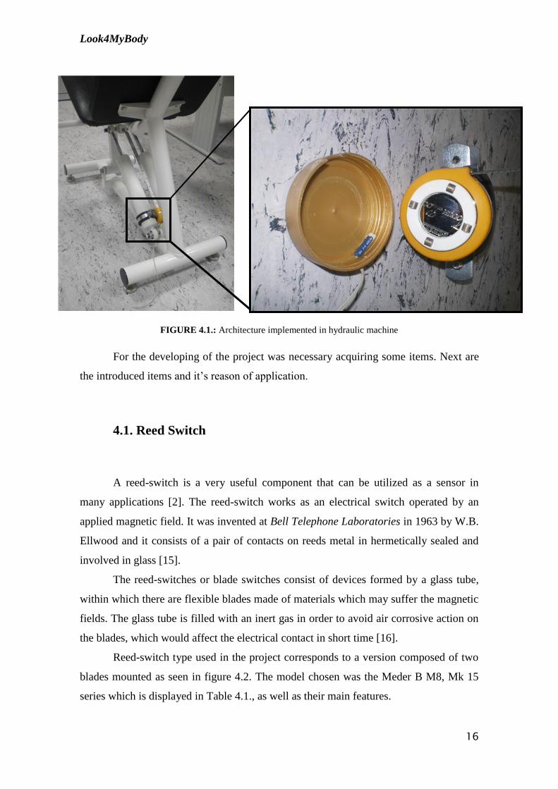
The architecture implemented in each hydraulic machine of the gym consists of
an adaptation of a measurement tape to the hydraulic resistance of the machine. This
tape has four magnets and a reed-switch which communicates with the hardware board
as can be seen in figure 4.1.
Look4MyBody
16
FIGURE 4.1.: Architecture implemented in hydraulic machine
For the developing of the project was necessary acquiring some items. Next are
the introduced items and it‟s reason of application.
4.1. Reed Switch
A reed-switch is a very useful component that can be utilized as a sensor in
many applications [2]. The reed-switch works as an electrical switch operated by an
applied magnetic field. It was invented at Bell Telephone Laboratories in 1963 by W.B.
Ellwood and it consists of a pair of contacts on reeds metal in hermetically sealed and
involved in glass [15].
The reed-switches or blade switches consist of devices formed by a glass tube,
within which there are flexible blades made of materials which may suffer the magnetic
fields. The glass tube is filled with an inert gas in order to avoid air corrosive action on
the blades, which would affect the electrical contact in short time [16].
Reed-switch type used in the project corresponds to a version composed of two
blades mounted as seen in figure 4.2. The model chosen was the Meder B M8, Mk 15
series which is displayed in Table 4.1., as well as their main features.

Look4MyBody
17
FIGURA 4.2: Reed Switch components [18]
TABLE 4.1.: Features of the reed-switch [18]
Under normal conditions, the blades are separated and none current can
circulate through the components. Approaching a permanent magnet of the device, a
magnetic field occurs which causes the blades to magnetize and thus attract to one
another, uniting. Under these conditions, the electrical contact is closed as can be seen
in figure 4.3. A magnetic field (from an electromagnet or a permanent magnet) will
cause the contacts to pull together, thus completing and an electrical circuit [17].
FIGURE 4.3.: Reed Switch closed. [16]
Reed Switch Features:
Excellent for low power operations
High power switches available
Six operate sensitivities available
Tape and Reel available
No external power required for sensor operation

Look4MyBody
18
In other words, the reed-switch makes contact between the blades depending on
the action of an external magnetic field.
The common reed-switches are low current devices. The usual types are
specified in order to control currents which do not pass the 200 mA input.
Finally, the reed-switch is a component that has a relatively high response rate.
Can be used to open and close the contacts rapidly by the passing of a magnetic field.
This allows it to be used as a rotations or movement sensor, as it‟s displayed in
Figure 4.4.
FIGURE 4.4: Tape-measure and reed switch [16]
The measurement tape within each gym device contains four magnets, which are
distanced by approximately 2cm and with a reed-switch as shown in figure 4.4.
On each passage of a magnet in front of the reed-switch, this is activated. This
produces a pulse that goes to a revolutions counter. It‟s possible to count with this kind
of sensor up to 100 laps per second, however in project, this does not happen. [16]

Look4MyBody
19
FIGURE 4.5: iButton F5 Microcan TM[19]
4.2. iButton
Each client got an iButton with the main function to provide us their own
identification. After several quests was chose all the items necessary to the
identification of the client.
Following this it‟s mentioned the chose items and its main characteristics.
4.2.1. iButton DS1990A
An iButton is a rugged data carrier that
serves as an electronic registration number for
automatic identification, known as the DS1990A
serial number iButton, transfering data serially
through the 1-Wire protocol. This requires only one
single data lead as well as a ground return. [19]
Allowing absolute traceability, every DS1990A is lasered at the factory with a
guaranteed unique 64-bit registration number. The iButton is designed for durability
with a stainless-steel package that is highly resistant to outside, environmental hazards
such as moisture, shock and dirt. The DS1990A is easily used by human operators due
to its coin-shaped, compact profile being self aligned with mating receptacles. The
DS1900A, with the use of accessories is enabled to be mounted on almost any object
including containers, bags and pallets. [19]
Operation
The internal ROM number of the DS1990A is accessed via a single data line.
With the use of the 1-Wire protocol the 48-bit serial number, 8 bit family code and 8-bit
CRC are retrieved (Figure 4.6.). This protocol defines bus transaction when it comes to
the bus state awhile specified time slots commenced on the falling edge of sync pulses
from the bus master. All data is read and written first the least significant bit. [19]

Look4MyBody
20
FIGURE 4.7: DS1990A equivalent circuit [22]
MSB 64-Bit’Registration’ ROM Number LSB
8-Bit CRC
MSB LSB
8-Bit Family Code
MSB LSB
48-Bit Serial Number
MSB LSB
FIGURE 4.6.: 64-Bit Unique ROM 'Registration' Number. [20]
1-Wire System
The 1-wire bus is a system composed by a single bus master system and one or
more slaves, and the DS1990A is a slave device on all instances. Commonly the bus
master is a microcontroller. The three topics this particular bus system has are broken
down into the following terms of discussion: hardware configuration, transaction
sequence, and 1-Wire signaling (signal type and timing). [21]
Hardware Configuration
There is only a single line by definition
to the 1-Wire bus and so it‟s important that
each device on the bus be able to drive it at the
appropriate time. Each one of the devices are
attached to the 1-Wire bus has to have an open
drain connection or a 3-state output in order to
make this easier. The DS1990A being an open
drain part with an internal circuit equivalent to
that shown in Figure 4.7. [21]
Look4MyBody
21
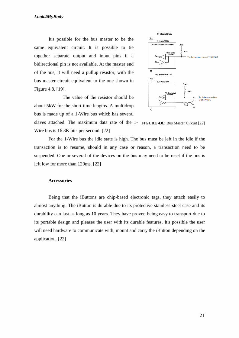
FIGURE 4.8.: Bus Master Circuit [22]
It's possible for the bus master to be the
same equivalent circuit. It is possible to tie
together separate output and input pins if a
bidirectional pin is not available. At the master end
of the bus, it will need a pullup resistor, with the
bus master circuit equivalent to the one shown in
Figure 4.8. [19].
The value of the resistor should be
about 5kW for the short time lengths. A multidrop
bus is made up of a 1-Wire bus which has several
slaves attached. The maximum data rate of the 1-
Wire bus is 16.3K bits per second. [22]
For the 1-Wire bus the idle state is high. The bus must be left in the idle if the
transaction is to resume, should in any case or reason, a transaction need to be
suspended. One or several of the devices on the bus may need to be reset if the bus is
left low for more than 120ms. [22]
Accessories
Being that the iButtons are chip-based electronic tags, they attach easily to
almost anything. The iButton is durable due to its protective stainless-steel case and its
durability can last as long as 10 years. They have proven being easy to transport due to
its portable design and pleases the user with its durable features. It's possible the user
will need hardware to communicate with, mount and carry the iButton depending on the
application. [22]

Look4MyBody
22
4.2.2. Reader DS9092
The DS9092 iButton Probe produces the required
electrical contact to dispatch data to and from the DS19xx family
of iButtons. Because of the round shape of the probe, a self
angling interface that promptly matches the circular rim of the
iButtons Microcan Package is provided. Metal contacts
withstand wear and are easy to maintain clean. [23][25]
The model reader´s center contact has no moving parts
and so making it a tougher interface for harsh environments.
When the iButton is brought into contact with the reader is when
this probe is best suited.
In situations when the iButton is stationary and the movable reader is brought
into contact with it, the tactile feedback probe is perfect. [23][25]
For a facilitated connection to the system microcontroller, two 15 cm 22AWG
wires are provided. A 10cm handle and a one meter cable with ends with an RJ11 jack
comes joined to the hand-grip mount probe. [23]
FIGURE 4.10.: Standard Probe [23]
FIGURE 4.9. Reader DS9092 [25]

Look4MyBody
23
TABLE 4.3: Key Features of DS9092 [23]
Key Features of DS9092
Simple, inexpensive stampings compose a read/write probe for the iButton
iButtons entry is guided by probe
To self clean contacts, iButton slides over the surface
To simplify removal of debris such as mud due to an achievable superficial probe
cavity
Adaptable design supports panel-mount or hand-grip mount with elective feedback
Millions of operations are provided by the bright discoloration-resistant metal surface
Prewired panel-mount to facilitate installation
For prompt installation, hand grip probe mates to RJ11 jack

Look4MyBody
24
4.2.3. Chip DS2480B
The DS2480B is a serial port to 1-Wire interface chip that supports regular and
overdrive speeds. It connects directly to UARTs and 5V RS232 systems. The DS2480B
uses a unique protocol that merges data and control information without requiring
control pins. In the fowling table, will be referred the main features of the DS2480B.
[24]
Features of the DS2480B
Universal, common-ground serial port to 1-wire ® line driver for microlan applications
Works with all ibuttons® and MICROLAN-compatible 1-wire slave devices
Communicates at regular and overdrive 1-wire speed and serial port data rates of 9600
(default), 19200, 57600, and 115200 bps
Supports 12V EPROM programming and stiff 5V pullup for crypto ibutton, sensors and
EEPROM
Load sensor to terminate the stiff pullup as the energy demand of the crypto ibutton drops
Self-calibrating time base with _5% tolerance for serial and 1-wire communication
Slew rate controlled 1-wire pulldown and active pullup to accommodate long lines and
reduce radiation
User-selectable RX/TX polarity minimizes component count when interfacing to 5V based
RS232 systems or directly to UARTS
Programmable 1-wire timing and driver characteristics accommodate a wide range of
MICROLAN configurations at regular speed
Smart protocol combines data and control information without requiring extra pins
Low-cost 8-pin so surface-mount package
Operates over 4.5V to 5.5V from -40°c to +85°c
TABLE 4.4.: Features of the DS2480B [24]

Look4MyBody
25
An IO pin on a microprocessor can generate the 1-Wire communication
protocol, never the less, precaution should be taken so that the correct timing and proper
slew rates are provided to create reliable 1-Wire network. The length of a network can
be seriously limited as well as create a sporadic behavior due to uncontrolled slew rates.
It is possible to rid of these problems. A serial communication UART is available
utilizing a serial-to-1-Wire bridge (DS2480B). The DS2480B is a serial bridge to the
one 1-Wire network protocol that permits almost any computer with a very moderate
serial communication UART to produce correctly timed slew controlled 1-Wire
waveforms. [21]
Escaped commands and data are received by the DS2480B and it in turn
accomplishes 1-Wire operations and revert the result back to the computer. It can take
up a lot of time and prove to be confusing applying this protocol and navigating the
available DS2480B. [21]
Computer RXD
UART
TXD
1-Wire Master
DS2480B
(Serial Bridge)1 – Wire Slave
iButton
DS1990A
FIGURE 4.11. DS2480B usage (simplified) [21]
The 1-Wire Interface
The DS2480B's usefulness relies on the capability its commands have to be
translated into a 1-Wire communication interface that applications can use and build on.
For any 1-Wire operation there are a few elementary 1-Wire functions that an
application must have. The 1-Wire master has to initiate all 1-Wire bit communication
and so „read‟ is in technical terms a 'write' of one bit with the result sampled. [21]

Look4MyBody
26
Hoste Configuration
The DS2480B's host must possess a UART with a capacity of at least 8-bit, non-
parity, 9600 baud communication. The UART's configuration is specific and has to
produce standard interface operations such as reading/writing, flushing pending
reads/writes, coming to a break and selectively changing the baud rate. [26]
DS2480B Configuration
The host has to be setup and in synchronization with the DS2480B Serial 1-Wire
line driver before any 1-Wire operations can be tried. This procedure of setup and
synchronizing is carried out if a problem is detected between the host and the bridge.
During setup the DS2480b need a 9600 baud. Before the following command is shifted
in, the prior provided 1-Wire command must be able to complete. [26]
o OWDetect
The DS2480B has no crystal and so it has to tune it's time-base by sampling the
serial communication the host sends. [26]
To initiate the setup sequence the DS2480B has to be reset and then send a
predefined timing byte. This will cause all the configurations of the 1-Wire parameters
to restart to their default state. It is advised that the DS2480B be used in 'flex' mode
when doing standard speed communication for a good performance on small to medium
length 1-Wire networks. [26]
Should a space in the stop-bit position be detected the DS2480B is reset. A serial
break that is no longer the 9600 baud, 8-bit word is the easy way to generate this. In the
absence of a break on the host UART it is possible to switch to slower baud rate and
send a zero byte to simulate a break. [26]
Delay values in the configuration sequence are normally large to support, so that
it too, can support most UART's but it is possible to reduce these values. [26]
To measure the correct functioning of the DS2480B setup, the read baud rate is
register and writes 1-Wire bit at the end of the setup sequenced is used and designed for
that purpose. The setup will be determined an unsuccessful should either one of these
operations return invalid response. [26]

Look4MyBody
27
1-Wire Operations
The act of implementing each of the 1-Wire operations has in common some
aspects. For the reduction of the number of exchanged packets with the DS2480B
commands and data are grouped together whenever possible. A packet may start with a
made changing because the current mode of the DS2480B is kept as state. [26]
o OWReset
The DS2480B is instructed by the OWReset operation to send a reset pulse to
the 1-Wire. The main objective of this instruction is to accomplish this reset operation
as well as it returns other information that is useful. It also supplies a three-bit field
indicating the version of the chip. Even though the version field will be constant with all
the DS2480B, it can however be utilized to detect the predecessor to the bridge, the
DS2480 and so making its implementation compatible. To make the host software or
firmware, whichever the case, at least partially compatible to the future bridge versions
can be accomplished by masking off this field. [26]
o OWSearch
The search algorithm is known as a tree search with branches that are followed
until a device's ROM number (or leaf) is found. Following searches take the other
branch paths until all of the present leaves are found. [26]
This search starts with the devices on the 1-Wire being reset utilizing the rest
presence pulse sequence. As a result the 1-byte search command is sent if this is a
success. The search command prepares the 1-Wire devices so that the search is initiated.
[26]

Look4MyBody
28
1-Wire search DATA Construction
It is possible to consider 16 bytes of 1-Wire search data into 128 bits of data that
is grouped into 64 2 bit pairs. The first bit should be 0 and is not used. If a discrepancy
is detected then the second bit is used. [26]
The DS2480B will proceed automatically with the only available path. The
search direction bits must be set to ROM-ID bits from the last search up until the last
discrepancy bit position when constructing the outbound data. At this stage, the search
direction set to one is therefore set them all to 0. [26]
128
0
127
0
L**
1
L-1
0
4
r2
3
0
2
r1*
1
0
* ROM_ID bist corresponding to the id_bit_number from a previous search. See Application Note
187
** LastDiscrepancy bit position. See Application Note 187
FIGURE 4.11. Outbound Search Data [26]

Look4MyBody
29
CChhaapptteerr 55
55.. SSyysstteemm AArrcchhiitteeccttuurree
In this chapter, is the meticulous description of the features of the embodied
components, their relationship and the environment where they are placed.
5.1. Physical Architecture
The gym monitoring system is made of hydraulic machines, each having
associated an acquisition plaque, a data view screen of a real-time exercise and a server,
where the program visualized will run.
FIGURE 5.1: Physical Architecture

Look4MyBody
30
The acquisition module, the transmission module and the processing module are
incorporated in the acquisition board.
Physically, the acquisition module is constituted by the iDemoboard and the
socket radio 868 MHz, which sends through radio antennas the data coming from
iButton and the Reed-switch to the Dongle Radio USB 868 MHz, which is connected
via USB to a server.
The server and the screen compose the visualization module. On the server are
also incorporated the report visualization modules and the database.
The reports contain information concerning the monitorization of physical
exercise performed by each client, who makes his identification with the iButton
assigned to him prior to the realization of the exercise.
After the client proceeds to his identification and start his training, the
monitorization of his exercise appears on a screen existent in the room, as can be seen in
Figure 5.2.
FIGURE 5.2. Presentation of the monitorization exercises

Look4MyBody
31
5.2. Logical Architecture
The system consists of a multi layer structure. The layer responsible of storing
the data concerning the solution is the database tier. The system is enlarged with a
Windows Application which is the system‟s interface to interact with its users.
Between the layers mentioned above is placed the logical tier which is composed
of an acquisition module as well as a report module. This tier is responsible for the flux
of data in the system and the coordination of data storage and measurements
FIGURE 5.3. Logical Architecture
Local Application
The local application corresponds to the windows application. Through this
application the client has access to the information referring to the exercises that are
executed during the session.
Furthermore, he has real-time access to data through a screen which displays a
chart with the values of spent calories as well as the distance travelled, in time.
The client can also access to his evolving history through the database that is
placed in the server, where the exercise data is registered.
This information can be consulted via the report module that provides the most
relevant statistics from the previous monitoring sessions.

Look4MyBody
32
o Client Management:
The people whose exercises are being monitored are the gym clients. These
clients have access to the information displayed in a screen in the gym, accessing to her
exercise information in real-time.
A personal will have access to the interface of the windows application on the
server, being able to manage the forms of the clients as well as the report modules.
o Real-time monitorization:
This module allows the registration of a new client in the database, in case it is
the person‟s first monitoring session and the monitoring session of the exercise is made
in real-time.

Look4MyBody
33
Chapter 6
6. System Development Tools
Before code writing and development, a firmware programmer must set up and
define his Development Environment.
A Development Cycle (process which is carried in an application development)
is formed by a cyclical operation constituted by four main steps. These steps are
Edit/Create/Design code, Compile/Assemble/Link code, device Programming and
Analyze/Debug firmware (see Figure 6.1). [5]
Compile /
Assemble /
Link code
Edit / Create /
Desing Code
Program
Device
Analize/Debug
firmware
FIGURE 6.1: Development Cycle.
Once defined the Development Process, one can proceed to the identification of
the Development Environment components which include the definition of a Compiler,
a Programmer/Debugger and integrated Development Environment software. In the
following topics it will be provided a brief overview on each component as well as the
reasons that led to their choice. [5]

Look4MyBody
34
6.1. Compiler
During the development process the PIC24FJ64GA004 used, microcontroller
architectures were approached.
Since the compiler is directly related with hardware architecture, was MPLAB
C30 with 16-bit PIC microcontrollers‟ devices.
A compiler is a set of rules that are applied in the translation of high-level
language statements into Assembly language. More recent compilers use advanced
techniques to simplify programming tasks, turning them more transparent, and to
optimize the assembler code. In this case, the term cross-compiler should be used
instead of just compiler, since it‟s running on a different platform than its creation one.
[5]
The main support tool to a programmer is the documentation, like books,
articles, tutorials, problem solving forums and code samples, which refer to the subject
of the work in progress. Thus, the amount of documentation available depends on the
chosen compiler and that must be taken in consideration in its choice. A commonly used
compiler like the C30 that uses PIC microcontroller C compilers has a wide variety of
documentation provided either by the official manufacturer or other programmers.
Also taken in consideration was its ability to facilitate the programmers‟ job, in
other words, the number of built-in functions and macros in the compiler that are used
by the programmer to control peripherals or access microcontrollers register should be
high.
The C30 compiler not only includes these low-level controlling macros and
functions but also has C libraries for memory management, input/output and other
libraries for general purpose that saves the developer some time and tedious work. [6]
[7]
Lastly, the easy integration with an integrated Development Environment was
another important feature that contributed to the choice of the compiler, since it
considerably reduces the time spent on the four developing cycle stages. MPLAB C30
compiler was planned with MPLAB IDE integration in sight. [7]

Look4MyBody
35
FIGURE 6.2: ICD2 [9]
6.2. Programmer/Debugger
After being compiled, assembled and linked, the program will access the
programming memory of the microcontroller. The process which allows the
microcontroller to run the program as a standalone is called Programming and consists
simply in transferring the final firmware into the chip.
When programming a microcontroller, if something fails, there is no output to
analyze so that the problem can be fixed. To surpass this concern it is used an In-
Circuit-Debugger that allows debugging the code while it is running on the PIC,
providing crucial information to the developer. This debugger is a piece of hardware
that is link through wires to both the computer and the system that is in test.[8]
Throughout the system‟s development it was used
an In-Circuit Debugger and an In-Circuit Serial
programmer device to maximize the developing
efficiency. The chosen device for this project was the
MPLAB ICD2 produced by the same company as the PIC
microcontrollers, Microchip. The ICD2 not only allows
the normal programming procedures but also provides
real time and single-step code execution. [8]
6.3. Integrated Development Environment
The most important part of the programmer‟s Development Environment is the
IDE (Integrated Development Environment) software. This software gives the
programmer, as the name implies, a single integrated environment that contains all the
necessary features to code development and testing. An IDE brings programmers the
necessary interfaces, supposedly user-friendly, so that they can use mouse clicking and
shortcuts instead of tedious command invocations, maximizing programmers‟
productivity. [5]
The purpose of the IDE is to maximize programmers‟ productivity by providing
an integrated and user-friendly single interface, in other words, programmers can

Look4MyBody
36
replace tedious command invocations in several applications by button clicking or
shortcuts in the same software application. [5]
The MPLAB IDE from Microchip is probably the only choice that provides total
integration with the compiler and the debugger/programmer simultaneously. This makes
this particular IDE one of most used among PIC programmers. [5]
In the following topics the most used MPLAB‟s built-in components will be
overviewed.
o Project Manager
The project manager aids in the organization of the source files of the firmware
project. This component is also responsible for the correlation between the IDE and the
language tools. [5]
o Editor
The editor besides being a source code editor, it also represents support to the
debugger module. The editor component from MPLAB is not as strong as other single-
purpose text editors. However this does not constitute a problem since C language does
not need a powerful tool to this purpose due to its simplicity. [5]
o Assembler/Linker
This component is transforms the assembly code that is returned by the compiler
into object code. This operation makes possible that the programmer‟s code is
transferred to the microcontroller. [5]
When there are several source files in the project, the linker and the assembler
must be used together. The linker makes two main operations. One of them is that it
links the several object code files generated by the assembler together into an
executable program. The other operation consists in the positioning of the code in its
proper memory areas of the microcontroller. [5]

Look4MyBody
37
o Debugging Tools
Although, MPLAB‟s debugging tools cover the most features of other
debuggers, including, as mentioned above, breakpoint, single stepping and
watch/modify variables, it has some limitations as well: the slow and poor
synchronization between the microcontroller and the IDE software. Nevertheless, the
existent method is a precious help to PIC programmers. [5]

Look4MyBody
38
6.4. Acquisition and Transmission Module
The iDemoBoard is a board-bearing tests and development of OEM modules of
ISA.
Essentially provides the power for the various modules, interfaces and
communication pin input / output. [27]
The iDemoBoard Support 3 OEM modules:
o Socket Radio 868MHz
o Socket Radio 2.4 MHz
o Socket Modem
o Socket Ethernet
The present iDemoboard provides regulated 3.3V and 5.0V. Contains interfaces
RS485, RS232 and USB serial module. [27]
This iDemoBoard has a sheet of 60-pin expansion, which can be seen in
attachment B and the schematics in attachment C. [27]
FIGURE 6.3.: General layout of the board

Look4MyBody
39
6.4.1. Description of the Hardware
o Power
The iDemoBoard can be powered with a 9-12V DC
voltage. [27]
FIGURE 6.4.: Power
o Radio Interfaces Modules
The radio modules have their Inputs and
Outputs directly linked to iDemoBoard. [27]
FIGURE 6.5.: Radio Interfaces Modules
o Origin of communication series – Radio
To select the source of the signals and serial
communication cable should be selected as shown in figure
6.6. for the Radio mode socket.[27]
Figure 6.6.: Serial Radio

Look4MyBody
40
6.5. Socket Radio 868 MHz
The Socket Radio is based on the Integration Silabs SI4421 Universal ISM Band
FSK Transceiver and the PIC24FJGA004. The Socket Radio is a ready-to-integrate
module for operation on the unlicensed 868 MHz ISM (industrial, scientific and
medical) band. [28] [29]
The Socket Radio 868 MHz is pin-compatible with the Socket Radio 2.4 GHz.
Their pin compatibility enables the easy migration from one technology to the other.
The schematics could be seen in attachments C. [28] [29]
FIGURE 6.7.: Devices that communicate with the Socket Radio [28]
TABLE 6.1: Applications of the Socket Radio 868 [28] [29]
Applications:
Home security and alarm Automated meter reading
Remote control Industrial automation
Telemetry Wireless sensors
Process Access and Building Controls Remote data logging
Home automation Personal Area Network
Home appliances interconnections PC peripherals

Look4MyBody
41
TABLE 6.2.: Features of the Socket Radio 868 [28] [29]
Features
Range 300m
Radio Frequency 868MHz
Dimensions 29,5 x 50,9mm
Antenna External SMA connector
Operating Temperature 0°C to 60°C
Power Consumption (µC+radio) Rx: Typ. 27mA, Tx: Typ. 38mA
Operating Voltage Range 2,8 - 3,6V
RF output power 7dBm
RF sensitivity -110dBm
I/O 2 Analog inputs, 4 Digital I/O, 1 SPI, 1 UART
RF data rate 0,6 - 115kbps
Two status indicator LEDs
Sleep mode
Low power consumption
Multipath fading and interference bypass
Allows frequency hopping
All RF peripheral components already integrated
UART and SPI interfaces
No RF knowledge required
Small footprint allows easy integration on OEM design product
2 LED
1 Configuration strap
1 Reset strap

Look4MyBody
42
6.5.1. Bridge UART 24F
This guide shows the necessary steps to be taken while programming and
configure of a UART bridge between two 868 MHz radio sockets. The Socket Radio
868 MHz are based upon the chips PIC 24FJ64GA004 and on the chip SI4421. The
UART bridge example code implemented on the PIC enables the transmission of data
forward to another radio module with the same firmware used. Thus, the connection
between UART < - > UART is transparent. [30]
In attachment 9.3.file shows a schematic of the 868 MHz showing all the
connections that should be made to enable its correct function. [30]
In Figure 6.8. can be seen a description of the several socket pins. The pins
marked in red should be essential since these
must be linked to the bridge mode P2P (peer
to peer). The socket should have a regulated
input power of 3,3 V and the inputs and
outputs are digital (RX_PIC e TX_PIC). [30]
o PIC Programming
The PIC should be programmed with the
“bridge24F.hex” firmware using an available
socket connection to the ICD programmer or
another compatible. The programming pins are
described in figure 6.9. [30]
FIGURE 6.9: Connecting to the type of
programming the ICD2 [30]
FIGURE 6.8.: Descriptions of the Socket Radio
868 MHz connections [30]

Look4MyBody
43
6.6. Dongle Radio USB 868 MHz
By incorporating the Silabs Integration SI4421 Universal ISM Band FSK
Transceiver and the PIC18F66J50, the USB Dongle 868 MHz supports a wide range of
applications operating on the unlicensed 868MHz ISM. The schematics could be seen in
attachment C. [31]
The Dongle Radio USB provides an easy way of integrating proprietary
protocols into personal computers, gateways or bridge devices. This solution is ideal to
be used in the establishment of networks in which the dongle may be configured to act
as the coordinator, router or a simple end device. [32]
FIGURE 6.10.: Devices that connect directly whit dongle [32]
TABLE 6.4.: Applications of the Dongle USB 868 [32]
Application:
Home security and alarm Automated meter reading
Remote control Industrial automation
Telemetry Wireless sensors
Home automation Remote data logging
Home appliances interconnections Personal Area Network
PC peripherals

Look4MyBody
44
TABLE 6.5.: Features of the Dongle USB 868 [32]
Features
Range 300m
Radio Frequency 868MHz
Dimensions 22,0 x 44,7mm
Antenna External SMA connector
Operating Temperature -10°C to 60°C
Power Consumption max: 50mA (µC+radio)
RF output power 7dBm
RF sensitivity -110dBm
RF data rate 0,6 - 115kbps
No need to develop USB drivers or RF design experience or expertise
On-Board Voltage Regulator: Dongle entirely powered from the USB Bus
Low Speed (1.5Mb/s) and Full Speed (12Mb/s) Compatible USB Serial
USB V2.0 Compliant Serial Interface Engine
Easy access to the AT command interface through an application software
High Bit Rate up to 115,2 kbps
Fast Frequency Hopping Capability
ISM (Instrumental, Scientific and Medical) 868MHz Band Operation
Small footprint allows easy integration on OEM design product
2 LED
1 Reset strap

Look4MyBody
45
6.6.1. Bridge UART Dongle Radio USB 868 MHz
The Dongle Radio USB 868 MHz are based upon the chips PIC18f66j50 and the
Si4421. The UART bridge example code implements the transmission of data regarding
a virtual series gate in the Pc forwarding it to another radio module with the same code
in use. Thus, the connection between UART<-> UART is transparent. [33]
o PIC programming
The PIC should be programmed with the
“bridgeUART_18F.hex” firmware using an
available socket connection to the ICD
programmer or another compatible. The
programming pins are described figure 6.11. [33]
FIGURE 6.11.: Connections of Dongle
USB 868 [33]

Look4MyBody
46
CChhaapptteerr 77
77.. FFiirrmmwwaarree DDeessiiggnn
Most of the work carried out during the past academic year is experienced
along this chapter. Despite being the project‟s main objective, firmware design was the
last stage to be performed. Previous chapters can be considered as intermediate
steps that aim to a common goal that's the development of the firmware transmission
modules that perform all the required tasks. Throughout this chapter, several concepts
approached in previous chapters, will be referenced. This way, in order to fully
understand present‟s chapter considerations, the reader must be entirely familiarized
with previous chapters.
Besides the actual firmware design sections, this chapter includes an additional
section that has the purpose to explain the communication protocols defined by
the programmer throughout firmware development stage.
The development of the present project‟s firmware required the usage of all the
equipment mentioned previously.
The iDemoBoard acts as a support to the Socket Radio 868 MHz which contains
the PIC24FJ64GA004. This PIC is programmed via an ICD2 that communicates with
the computer via USB. The computer must have installed the MPLab to process the
code. Throughout the firmware development, the iDemoboard had a reed-switch and a
chip DS2480B to which a reader DS1990A was attached, as it can be visualized in
scheme 7.1.

Look4MyBody
47
Reed-
Switch
1-Wire Line
Driver
Socket Radio
868 MHz
MPLab
ICD2
FIGURE 7.1: The most used devices during the firmware development
7.1. Firmware Description
The firmware projects aims to make the communication with the Socket Radio
868 MHz and the Dongle Radio USB 868 MHz via radio, sending the pulse counting as
well as the client identification.
For each hydraulic machine there are a measure tape with four magnets and a
reed switch (see figure 7.2.). Between each magnet there is a distance of approximately
2cm. For each time the magnet passes through the reed-switch a measurement takes
place.
FIGURE 7.2.: Hydraulic Machine with measure tape which has four magnets and a reed switch.

Look4MyBody
48
The tape measure is calibrated so that the distance between each magnet is 2 cm.
So, whenever there's a passage of the magnet by Reed switch the count of a pulse is
made, to this pulse is added 2 cm.
Each time that a pulse is counted; this data is sent from the socket radio 868
MHz to the Dongle Radio USB 868 MHz via radio. On the computer where the Dongle
Radio USB 868 MHz is entered, the data is collected in a form as presented in figure
7.3. Afterwards; these results are sampled in the chart, as in Figure 7.4.
FIGURE 7.3. A form with the counting pulses
FIGURE 7.4. Chart with the monitorization of the exercise
The identification of the iButton is sent each time the client places the iButton in
contact to the machine‟s reader that is pretended to use.
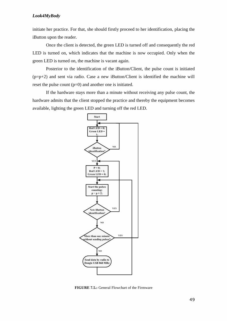
The general design of the firmware is presented in the flowchart seen in figure
7.5.
Initially, when the hardware is connected, the green LED is lighted and the red
LED is turn off, indicating to the client that the equipment is available and she could
Look4MyBody
49
initiate her practice. For that, she should firstly proceed to her identification, placing the
iButton upon the reader.
Once the client is detected, the green LED is turned off and consequently the red
LED is turned on, which indicates that the machine is now occupied. Only when the
green LED is turned on, the machine is vacant again.
Posterior to the identification of the iButton/Client, the pulse count is initiated
(p=p+2) and sent via radio. Case a new iButton/Client is identified the machine will
reset the pulse count (p=0) and another one is initiated.
If the hardware stays more than a minute without receiving any pulse count, the
hardware admits that the client stopped the practice and thereby the equipment becomes
available, lighting the green LED and turning off the red LED.
FIGURE 7.5.: General Flowchart of the Firmware

Look4MyBody
50
7.2. General Identification process of the iButton
This process was made with assistance of the Application Note (192), (187) and
the DS1990A datasheet that can be found in annex. Subsequent to the detailed reading
of these three documents, it was detected all the commands that were needed to achieve
the identification of the iButton. [19][21][26]
Previously, it has occurred an iButton analysis as well as its associated
components, using the RS232 communication and reading the sent/received commands
through a HyperTerminal. Only when the ROM number of the iButton was obtained,
the programming of the PIC 24 to the iButton identification was possible. [19][21][26]
In order to properly identify the iButton it's necessary to make three fundamental
checks, as can be verified in figure 7.6. When the iButton identification process is
initiated, it's necessary in first place, to detect the presence of the DS2480B, and then a
reset to the DS2480B must be done. Following the reset, ROM number should be found
in order to proceed with the decoding until the iButton ID is obtained. [19][21][26]
FIGURE 7.6: Identification process of iButton

Look4MyBody
51
7.2.1. How to detect the presence of the DS2480B
The process of detecting the presence of DS2480B chip is initiated through the
sending of a C1 (hexadecimal) command and a reply may or may not be sent back.
Whatever the reply is, it should be ignored. [19][21][26]
Subsequently, a command with 5 bytes (16 45 5B 0F 91) should be sent and the
reply should match 5 bytes (16 44 5A 93). Case the reply obtained matches the desired
reply it means that the DS2480B chip was detected; otherwise the previous steps should
be repeated again until the desired reply is obtained. [19][21][26]
FIGURE 7.7.: Detect the presence of the DS2480B

Look4MyBody
52
7.2.2. How to reset the DS2480B
To reset the DS2480B, a 2 byte command (E3 C5) must be sent. There are two
kinds of replies (CD and CF) that should be considered to determine that the reset was
concluded and each one occur depending on the presence, or not, of an iButton in
contact with the reader. [19][21][26]
When the answer is CD it means that the iButton is in contact with the reader if
CF is the reply, this means that the iButton is not in contact with the reader.
[19][21][26]
FIGURE 7.8.: Reset to the DS2480B flowchart

Look4MyBody
53
7.2.3. How to Search the ROM number from iButton
To obtain the CD-ROM drive number of the iButton when in contact with the
reader is necessary to send a command of 22 bytes for the DS2480B, E1 F0 E3 B5 FF
FF FF E1 FF FF FF FF FF FF FF FF FF FF FF 33 E3 A5. If the answer obtained
matches 16 bytes, the number is extracted. Otherwise the previous steps must be done
again. [19][21][26]
When the 16 bytes that match the ROM number are obtained, they will enter a
decoding procees until the iButton identifier matches 8 bytes. [19][21][26]
FIGURE 7.9.: Extract ROM number and iButton identification

Look4MyBody
54
7.2.3.1. iButton decoding
When the iButton ROM number is identified (16 bytes), it must be decoded until
the iButton ID is obtained (8 bytes). First of all, all bytes must pass to bits and fill the
table seen below. [19][21][26]
TABLE 7.1: 16 bytes of the ROM number converted into bits.
0 1 2 3 4 5 6 7
1º A 1,0 A 1,1 A 1,2 A 1,3 A 1,4 A 1,5 A 1,6 A 1,7
2º A 2,0 A 2,1 A 2,2 A 2,3 A 2,4 A 2,5 A 2,6 A 2,7
3º A 3,0 A 3,1 A 3,2 A 3,3 A 3,4 A 3,5 A 3,6 A 3,7
4º A 4,0 A 4,1 A 4,2 A 4,3 A 4,4 A 4,5 A 4,6 A 4,7
5º A 5,0 A 5,1 A 5,2 A 5,3 A 5,4 A 5,5 A 5,6 A 5,7
6º A 6,0 A 6,1 A 6,2 A 6,3 A 6,4 A 6,5 A 6,6 A 6,7
7º A 7,0 A 7,1 A 7,2 A 7,3 A 7,4 A 7,5 A 7,6 A 7,7
8º A 8,0 A 8,1 A 8,2 A 8,3 A 8,4 A 8,5 A 8,6 A 8,7
9º A 9,0 A 9,1 A 9,2 A 9,3 A 9,4 A 9,5 A 9,6 A 9,7
10º A 10,0 A 10,1 A 10,2 A 10,3 A 10,4 A 10,5 A 10,6 A 10,7
11º A 11,0 A 11,1 A 11,2 A 11,3 A 11,4 A 11,5 A 11,6 A 11,7
12º A 12,0 A 12,1 A 12,2 A 12,3 A 12,4 A 12,5 A 12,6 A 12,7
13º A 13,0 A 13,1 A 13,2 A 13,3 A 13,4 A 13,5 A 13,6 A 13,7
14º A 14,0 A 14,1 A 14,2 A 14,3 A 14,4 A 14,5 A 14,6 A 14,7
15º A 15,0 A 15,1 A 15,2 A 15,3 A 15,4 A 15,5 A 15,6 A 15,7
16º A 16,0 A 16,1 A 16,2 A 16,3 A 16,4 A 16,5 A 16,6 A 16,7

Look4MyBody
55
Based on the table, first of all the 1st iButton ID byte will be decoded, using the 1
st
and 16th
byte of the iButton ROM number received. Starting by withdrawing to the 1st
byte the even number match bites (0 included):
MSB = A 1,0; A 1,2 ; A 1,4; A 1,6
+
Afterwards, withdraw to the 16th
byte the even number match bites, 0 included:
LSB = A 16,0; A 16,2; A 16,4; A 16,6
=
Then add the MSB and LSB bits and obtain in hexadecimal.
MSB + LSB= A 1,0; A 1,2 ; A 1,4; A 1,6 ; A 16,0; A 16,2; A 16,4; A 16,6 = 1º ID
Identifier
Afterwards the process described above is repeated, however decoding the even
pairs, starting in the 15th byte;
o Decoding Table
TABELA 7.2: Decoding table
o Code decoded (8 – BYTES):
ID1 ID2 ID3 ID4 ID5 ID6 ID7 ID8
1º&16º A 1,0 A 1,2 A 1,4 A 1,6 A 16,0 A 16,2 A 16,4 A 16,6 ID1
15º & 14º A 15, 0 A 15,2 A 15,4 A 15,6 A 14,0 A 14,2 A 14,4 A 14,6 ID2
13º & 12º A 13,0 A 13,2 A 13,4 A 13,6 A 12,0 A 12,2 A 12,4 A 12,6 ID3
11º & 10º A 11,0 A 11,2 A 11,4 A 11,6 A 10,0 A 10,2 A 10,4 A 10,6 ID4
9º & 8º A 9,0 A 9,2 A 9,4 A 9,6 A 8,0 A 8,2 A 8,4 A 8,6 ID5
7º & 6º A 7,0 A 7,2 A 7,4 A 7,6 A 6,0 A 6,2 A 6,4 A 6,6 ID6
5º & 4º A 5,0 A 5,2 A 5,4 A 5,6 A 4,0 A 4,2 A 4,4 A 4,6 ID7
3º & 2º A 3,0 A 3,2 A 3,4 A 3,6 A 2,0 A 2,2 A 2,4 A 2,6 ID8

Look4MyBody
56
The process that was mentioned above is schematized in the following
flowchart, as well as the various stages of the decoding process which is briefly
presented in a block diagram. [19][21][26]
FIGURE 7.10: Flowchart of iButton decoding

Look4MyBody
57
FIGURE 7.11: Block diagram of the decoding of the iButton

Look4MyBody
58
7.3. Communication Technologies
The need to communicate with larger amounts of data promoted the serial
communication. This way, it consists on sending a sequence of data bits along the same
line with a predetermined frequency. Two devices serially connected with each other
can, this way, communicate unlimited amount. [35]
The purpose of short-range wireless communication technologies in the system‟s
context is to provide monitoring of the physical exercise data transmission from the
client‟s location into the transmission module, located nearby. [35]
The wireless personal area network (WPAN) concept seems to be the most
suited to this particular application since it interconnects devices around a person‟s
workspace wirelessly. In order to achieve optimum flexibility, security and
compatibility, standards based solutions must be used. Several wireless technologies
have been studied, but the technology used was RF. [34]
The following information will appear on this technology and how the chip used
in the Dongle Radio USB 868 MHz permit the communication.
FIGURE 7.12.: Block Diagram Radio Communication

Look4MyBody
59
CChhaapptteerr 88
88.. CCoonncclluussiioonn
The project Look4MyBody was developed in order to conclude the master
degree in Biomedical Engineering. Its main feature is the remote monitoring of physical
exercise in real-time. This project aims to provide for all the women that usually attend
this gym concept.
The main goals proposed concerning the firmware development were achieved.
Throughout the firmware development, a source code was developed with the ability to
count the pulses detected by the reed-switch. These pulses translate the distance made
by a client in a gym's machine.
It was also developed a system to identify the client since each one has an
iButton to identify herself. A code was developed to extract a ROM number existent in
the iButton. Then, this ROM number is decoded in order to obtain an ID that identifies
the iButton and, consequently, the owner of the iButton.
Some suggestions for future works are presented below, as well as an overall
assessment of the project. This assessment has two approaches. Firstly, the student
presents the benefits that this kind of gym brings to society. Secondly, the student
exposes her opinion on the project theme.

Look4MyBody
60
8.1. Future Works
Following, some suggestions for a future work development in this project are
presented.
In a short-term effort, firstly it must be established an appropriate hardware
adapter to be installed on each machine of the gym, since the hardware material used for
firmware development was improvised by intern in order to achieve the goals that were
proposed during the year.
It should also be explored and analyzed communication protocols, in order to
choose the one to perform the function of 8 devices included in the same room to
communicate with a Dongle Radio USB 868 MHz.
The firmware developed has been tested only for a single machine of the gym to
communicate with the Dongle Radio USB 868 MHz, it is necessary to test it in parallel
with the other hydraulic machines.
In the gym screen, when the chart with the monitoring exercise of the client
appears, a video should appear simultaneously, to indicate how the exercise should be
done correctly, stressing out the muscles that are being exercised in a specified exercise.
This way the client feels more motivated to perform the exercise correctly in order to
exercise the muscle perfectly.
In long term, it should be developed a way for the client to be identified on each
machine of the circuit, and the machine should know what training the client must
perform, and thus give feedback to client, indicating whether the effort/training
performed is the appropriate, overstated or insufficient.
In long term should also be included some vital signs on the physical exercise
remote monitoring system.

Look4MyBody
61
8.2. Final Appreciation
Nevertheless, this new concept presents a few gaps due to the fact that currently
there is no physical exercise monitoring devices. Usually, women tend to seek the
information about the time they are dispending, the distance travelled, and above all, the
calories they dispend throughout the physical exercise.
From a personal point of view I believe that the project might have an immense
commercial component, because, despite the circuit training being a novelty, women are
adhering massively to this kind of modality since it is a quick practice, easy and
complete.
As for personal benefits, the student appreciation is positive despite the initial
objectives changed through the run of the project. The student feels accomplished for
the work developed, for the obstacles she surpassed, for the dynamism presented, team
spirit, independence and knowledge acquired.
This project prove itself very constructive in the way that it provided the
opportunity for the student to learn and extend her knowledge, which was highly
appreciated by the student, together with the fact that its subject is inserted in the field
of electronics and firmware programming.
In addition, the enterprise environment where the student participated offered
not only a valuable help in the progress of the project but it was also important for her
to get perspective of the professional world and to develop and consolidate team
aptitudes. The fact that this project is divided by two students also helped in the latter
aspect since a good sense of team work was crucial to reach a common goal.
The wide variety of difficulties encountered throughout the project‟s evolution
was surpassed with high dedication and external help that granted the student an
increase in her problem solving competences.

Look4MyBody
62
8.3. Test and Final Results
The phase test is an integral part of the system development phase. It can
provide confidence in the system, identify weak areas of and establish the degree of
quality. The test domain has a wide range of types: unit, functionality, usability,
interface, performance, security, among others.
Were performed tests to the system's hardware, and were made iDemoboard
tests jointly with the Socket Radio 868 MHz a Dongle Radio USB 868 MHz. In all
these equipments were performed electrical checks as well as static tests and dynamic
tests, which are presented in annex.

Look4MyBody
63
REFERENCES:
[1] – VIVA FIT, Consulted at home, August 2009, < www.vivafit.pt/>.
[2] –ABOUT CURVES, Consulting at home, August 2009 < http://www.curves.com/>
[3] – INTELLIGENT SENSING ANYWHERE, consulting at ISA, September 2009, <http://www.isa.pt/>
[4] – GROUP OF ELECTRONICS AND INSTRUMENTATION, Consulting at home, August 2009,
<http://lei.fis.uc.pt/>
[5] - MPLAB IDE User's Guide, Microchip, 2006.
[6] - HI-TECH. PICC 18. Consulted at home, August 2009,
<http://microchip.htsoft.com/products/compilers/picc18procompiler.php.>
[7] - Microchip. MPLAB C Compiler for PIC24 MCUs, consulted at home, August 2009,
<http://www.microchip.com/stellent/idcplg?IdcService=SS_GET_PAGE&nodeId=1406&dDocName=en
010065>.
[8] - MPLAB ICD2 User's Guide. Microchip. 2007.
[9] - INDEX OF /IMAGES/GALLERY, Consulted at home, August 2009
<http://www.petrolia.com/images/gallery/Microchip-ICD2.jpg>.
[10] – PLUX SPORTS, Consulted at ISA, August 2009, <http://www.plux.info/sports>
[11] – PLUX HEALTHCARE, Consulted at ISA, August 2009 <http://www.plux.info/healthcare>
[12] – PLUX SENSORS, Consulted at ISA, August 2009, <http://www.plux.info/?q=webfm_send/46>
[13] – Wireless biosignals, Consulted at ISA, August 2009, http://www.plux.info/?q=webfm_send/47
[14]- CurveSmart, Consulted at University, August 2009,
<http://bethanybeachnews.com/content/curvesmart_%E2%80%94_digital_
personal_trainer_your_fingertips>
[15] – Reed-Switch, Consulted at home, August 2009, <http://en.wikipedia.org/wiki/Reed_switch>
[16] - Reed-Switches, Consulted at home, August 2009,
<http://www.mecatronicaatual.com.br/secoes/leitura/51>
[17] - Vladimir Gurevich "Electronic Devices on Discrete Components for Industrial and Power
Applications", CRC Press, London - New York, 2008, 418 p.
[18] – Reed-Switches, Consulted at home, August 2009, <http://www.eleinmec.com/article.asp?23>
[19] – MAXIM, Serial Number iButton, consulted at home, August 2009, <http://datasheets.maxim-
ic.com/en/ds/DS1990A.pdf>
[20]- MAXIM, Application Note 192, consulted at home, August 2009 <http://pdfserv.maxim-
ic.com/en/an/AN192.pdf>
[21] – MAXIM, Application Note 187, consulted at home, August 2009, <http://www.maxim-
ic.com/appnotes.cfm/an_pk/187>

Look4MyBody
64
[22]- MARCEL, DS1990A, consulted at home, August 2009,
http://electronique.marcel.free.fr/dsPIC/Programmes/iButton/Documents%20 ressources/ds1990A.pdf
[23] – DALLAS, DS9092 iButton Probe, consulted at home, August 2009, <http://datasheets.maxim-
ic.com/en/ds/DS9092-DS9092T.pdf>
[24] –DALLAS, DS2480B Serial 1-Wire Line Driver with Load Sensor, consulted at home, August 2009,
< http://datasheets.maxim-ic.com/en/ds/DS2480B.pdf>
[25] – MAXIM, iButton Products: Readers and 1-Wire Adapter, consuted at home, August 2009
<http://www.maxim-ic.com/products/ibutton/ibuttons/blue_dot.cfm>
[26] – MAXIM, Using the DS2480B Serial 1-Wire Line Driver, consulted at home, August 2009,
<http://www.maxim-ic.com/appnotes.cfm/an_pk/192>
[27] – ISA, OEM Modules, consulted at home, August 2009,
<http://www.isalabs.com/products/OEMmodules4.htm>
[28] –ISA, OEM Modules, consulted at home, August 2009,
<http://www.isalabs.com/products/OEMmodules5.htm>
[29] – ISA, Socket Radio 868 MHz, consulted at ISA, August 2009,
<http://www.isalabs.com/products/docs/SocketRadio_PB_r.pdf>
[30] – Internal documentation about Socket Radio 868 MHz, 2009
[31] – ISA, OEM Modules, consulted at ISA, August 2009,
<http://www.isalabs.com/products/OEMmodules2.htm>
[32] – ISA, Dongle Radio USB 868 MHz, consulted at ISA, August
2009http://www.isalabs.com/products/docs/Radio_USB_Dongle_PB_r.pdf
[33] – Internal Documentation about Dongle Radio USB 868 MHz
[34] – Wikipedia, WPAN, consulted at home, August 2009, <http://pt.wikipedia.org/wiki/WPAN>
[35]- WirelessCommunication, consulted at home, August 2009, <http://www.ict.nl/d/short-range-
wireless-communication/file/ShortrangeWirelessCommunication.pdf>
Other Bibliography Consulted
Varelas, Nuno, Remote Vital Signs Monitoring - Data Processing and Transmission Module, Coimbra,
September 2008.
Matos, Tomé, Remote Vital Signs Monitoring - Instrumentation Module, Coimbra, September 2008.
Simões, Rafael, Remote Vital Signs Monitoring - Software Module, Coimbra, September, 2008.
Hellebuyck, Chuck, Programming PIC Microcontrollers with PicBasic, Elsevier Sciences, 2003
Sickel, Ted Van, Programming Microcontrollers in C, Technology Publishing, 2001.
Jasio, Di Lucio, Programmming 16-bit Microcontrollers in C, Newnes, 2007.
Predko, Myke, Programming and Customizing, McGraw-Hill, Second Edition.
Centro de computação, Introdução á liguagem C, UNICAMP, versão 2.0

Look4MyBody
65
Pardue, Joe, C Programming for Microcontrollers, Knoxville, Smiley Micros, 2005
Microchip, PIC24FJ64GA004 Family Data Sheet, © 2008 Microchip Technology Inc.

Look4MyBody
66
AAttttaacchhmmeennttss
A. Muscles Worked in Hydraulic Machines Circuit
o Biceps and Triceps
This is a double positive machine. It works biceps and triceps, the client has to
pull the pads toward themselves to work the biceps and pushing the pads down and
away from themselves to work the triceps. [2]
Figure A.1: Biceps and Triceps [2]
o Leg Extension and Leg Curl
This machine works two types of muscles simultaneously. It works the
quadriceps and hamstring muscles. The client has to extend her legs and lift the pads to
work her quadriceps, and then has to bring the legs and the pads in to work her
hamstrings. [2]
Figure A.2.: Leg extension and led curl [2]

Look4MyBody
67
o Shoulder Press and Lat Pull
This machine has the ability to work two types of muscle at the same time. It
works the trapezius, deltoid and latissimus dorsi muscles on the upper body of the
client. [2]
The client has to push up on the machine, working primarily the deltois muscles,
and has to pull down on the machine working the trapezius and latissimus dorsi
muscles. [2]
Figure A.3.: Soulder Press and Lat Pull [2]
o Leg Press
This is a single positive machine. It works the quadriceps, hamstrings, gluteals
and ilopsoas. [2]
The client has to push the pedals away from her working well the quadriceps,
hamstrings, gluteals and iliopsoas. And then the client has to allow the pedals to slowly
return to the start position. [2]
Figure A.4: Leg Press [2]

Look4MyBody
68
o Abdominal and Back
This is a double positive machine. It works the abdominal and erector spinae
muscle groups. [2]
The client has to grasp the handles and then curl back to work the erector spinae
muscles. Then push down on the handles using our abdominal muscles. And then
curling forward and bringing the handles down works the abdominal muscles. [2]
Figure A.5: Abdominal and Back [2]
o Hip abductor and adductor
This is a double positive machine. It works the adductor and tensor fasciae latae
muscles. The client has to move the legs outward, working the tensor fasciae latae
muscles and moving the legs together works the adductor muscles. [2]
Figure A.6.: Hip abductor and adductor [2]

Look4MyBody
69
o Chest and Back
This is s double positive machine. It works the rhomboids, latissimus dorsi, and
pectoralis major muscles. [2]
The client has to push out on the handles working the pectoralis major muscles.
And then pull back, working the rhomboid and latissimus dorsi muscles. [2]
Figure A.6.: Chest and Back [2]
o Squat
This is a single positive machine. It works the quadriceps, hamstrings, gluteals
and iliopsoas. [2]
The client has to move down slowly until her thighs are parallel with the floor
works the quadriceps, hamstrigs, gluteals and ilipsoas against gravity. And then pushing
the pads up quickly working the quadriceps, hamstrings, gluteals and iliopsoas. [2]
Figure A.7.: Squat [2]

Look4MyBody
70
FIGURE B.9.: Board Suport iDemoBoard
FIGURE B.10.: Socket Radio 868
FIGURE B.11.: Socket TX and RX LED
B. Hardware Tests and Results
B.1. iDemoBoard and Socket Radio 868 MHz
The hardware plan test uses the
support hardware iDemoBoard. The
adapter does not need to have installed all
the component, considering that are
already installed a input power of 3.3V,
sockets and support chips.
Bridge UART Use
To test the functioning mode of the
UART bridge it is necessary two 2.4GHz
socket modules both programmed with the
same firmware. With the functioning mode
of the UART bridge is made a virtual
connection between all the surrounding
modules that can be listened. When that
connection is made, it is possible to send
and receive data via series with 9600 bauds,
8 bits and 1Stopbit. [29]

Look4MyBody
71
Electrical Verification
Static Tests
TABLE B.1.: Static Tests on Socket Radio 868
Dynamic Tests
TABLE B.2.: Dynamic Tests on Socket Radio 868
Parameter Expected Value Result Validation
VCC (J1.11 and J1.2) 3.30 V 3.28 V OK
SLEEP(J1.10) 3.30 V 3.25 V OK
RESET(J1.9) 3.30 V 3.28 V OK
CS_MEM (J1.8) 3.30 V 3.28 V OK
J1.7:5 0.00 V 0.00 V ( J1.5 = 0.125V) OK
J1.13:16 3.30 V 2.28 V OK
Consumption S1 (12..14)+(15..27)
27 mA … 41 mA
30 mA Typical
36 mA Max OK
Parameter Result Validation
Programming and verification of
the PIC with ICD2
PIC correctly recognized,
programmed and verified OK
Connecting the RS232 to the PC
after do reset, the Welcome
message appears in the terminal
Received “Welcome! Firmware
Test V.020” OK
The board are with LEDs all
erased, except the LED of the
power
All LEDs are erased except the
power LED OK
Press S3 on the board of support Received OK OK
Press S2 on the board of support Received OK OK
Press S0 on the Socket Radio 868 Received OK OK
All LEDs are lit LEDs all lit in this point OK
Potentiometer in 0V Received OK OK
Potentiometer in 3.3V Received OK OK
Potentiometer in 1.65V Received OK OK
All LEDs are erased Deleted all LEDs in this point OK

Look4MyBody
72
B.2. Dongle USB 868 MHz
The hardware SPE.IPR040- dongle USB 868 requires a PC with a USB link and
the “mchpcdc” drivers that can be found on the tests archive. To test the test point it is
needed a multimeter. To ease the test, should be made a query to the design and
schematic of the PCB adapter in order to detect easily the points that could be tested or
verified.
FIGURE B.13.: Dongle seen from above FIGURE B.14. : Dongle seem from bottom view
o Bridge P2P Use
To test the functioning mode of the UART bridge is necessary two 868MHz
USB dongle or a 868MHz socket module programmed with compatible firmware.
In a Terminal Software, is used a series gate created for the communication
between modules. The series gate does not need to have a baudrate configuration or the
others since it is a virtual series connection via USB. The USB dongle will accept
requests from other USB dongles or the 24GHz socket modules. [32]

Look4MyBody
73
Electrical Verification
Static Tests
Parameter Expected Value Result Validation
Resistance in power terminals
(G1 and P1) with the circuit off 200 K -200 K (0.2M) OK
Diode voltage of USB (P3) 5.00V-0.70V = 4.3V 4.21V OK
3.3V output voltage of the
regulator, after the connected
module (P2)
3.30V 3.29V OK
Consumption (12..20)+(12..27)
24mA..47mA
Typ: 27mA
Max:29mA OK
TABLE B.3. Static Tests on Dongle USB
Dynamic Tests
TABLE B.4.: Dynamic test on Dongle USB
Parameter Result Validation
Programming and verification of PIC
ICD2 with or similar
PIC recognized, properly
programmed and verified OK
Connecting the module to the PC, this is
recognized and found the correct drivers
Module recognized and installed
drivers and new COM port
detected
OK
Writing data to the terminal, data is
transmitted and received by another
module USB
Transmission of data is correct OK
Writing data to the terminal of another
radio module, the data is received by the
module in test
There is proper reception of data OK

Look4MyBody
74
B.3. Connector for Expansion
TABLE B.5.: Connector for Expansion [27]

75
C. Hardware Schematics
C.1. iDemoBoard

75

Look4MyBody
77
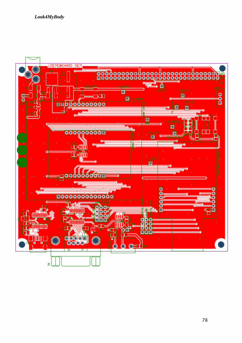
Look4MyBody
78

Look4MyBody
79

Look4MyBody
80
C.2. Socket Radio 868 MHz

Look4MyBody
81

Look4MyBody
82
C.3. Dongle Radio USB 868

Look4MyBody
83

Look4MyBody
84