lm actuator lm guides and qz lubricator for ball screw … · lm guides and qz lubricator for ball...
TRANSCRIPT
LM ACTUATOR
GL-N
CATALOG No.178ETOKYO. JAPAN
Equipped with Caged BallLM Guides and QZ Lubricatorfor Ball Screw
US OnlyQuick Delivery
* Standard options only. Please refer to list in page 7.
Cover
Timing belt
Table
Belt mounting plate
End plate
Housing
Timing pulley & pulley mounting bracket
Aluminum base
Caged Ball LM Guide
1
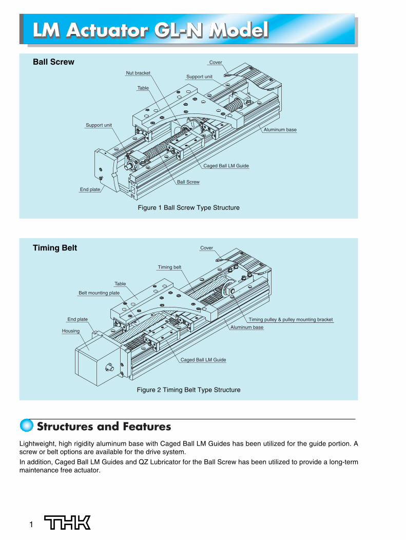
Figure 1 Ball Screw Type Structure
Lightweight, high rigidity aluminum base with Caged Ball LM Guides has been utilized for the guide portion. Ascrew or belt options are available for the drive system.
In addition, Caged Ball LM Guides and QZ Lubricator for the Ball Screw has been utilized to provide a long-termmaintenance free actuator.
LM Actuator GL-N ModelLM Actuator GL-N ModelLM Actuator GL-N ModelCover
Support unitNut bracket
Table
End plate
Aluminum base
Caged Ball LM Guide
Ball Screw
Support unit
Figure 2 Timing Belt Type Structure
Timing Belt
Ball Screw
Structures and Features
2
● Utilizing Caged Ball LM Guide (SSR, SHS)SSR model: Due to its 90-degree ball contact structure, is best suited to horizontal applications with relatively
low moment loads.
SHS model: It can handle loads from all directions (radial, reverse radial, and horizontal) with its 4-way equal
● Drive System
[Ball Screw Type]Variety of screw leads can be selected.
For wrap-around motor types, three motor directions (left, right and bottom) can be selected. (See page4 for details.)
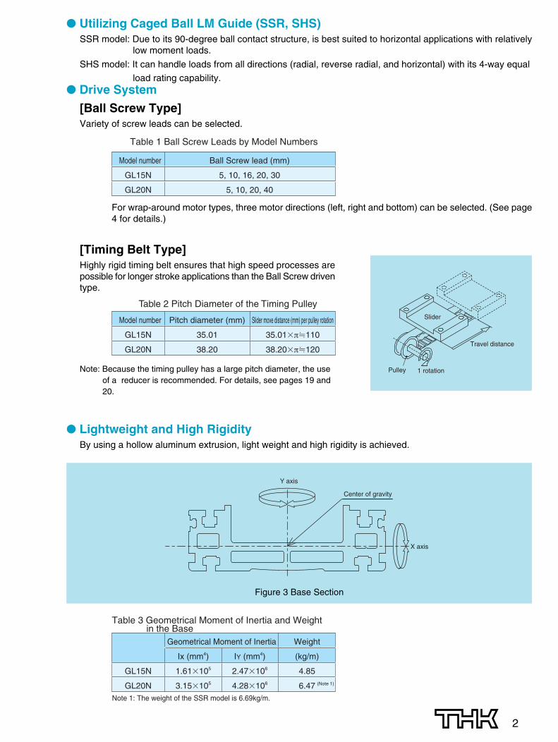
Figure 3 Base Section
Model number Ball Screw lead (mm)
GL15N 5, 10, 16, 20, 30
GL20N 5, 10, 20, 40
Table 1 Ball Screw Leads by Model Numbers
[Timing Belt Type]Highly rigid timing belt ensures that high speed processes arepossible for longer stroke applications than the Ball Screw driventype.
Note: Because the timing pulley has a large pitch diameter, the useof a reducer is recommended. For details, see pages 19 and20.
● Lightweight and High RigidityBy using a hollow aluminum extrusion, light weight and high rigidity is achieved.
Geometrical Moment of Inertia Weight
Ix (mm4) IY (mm4) (kg/m)
GL15N 1.61�105 2.47�106 4.85
GL20N 3.15�105 4.28�106 6.47
Table 3 Geometrical Moment of Inertia and Weight in the Base
Note 1: The weight of the SSR model is 6.69kg/m.
(Note 1)
Model number Pitch diameter (mm) Slider move distance (mm) per pulley rotation
GL15N 35.01 35.01�π�110
GL20N 38.20 38.20�π�120
Table 2 Pitch Diameter of the Timing PulleySlider
Pulley 1 rotation
Travel distance
X axis
Y axis
Center of gravity
load rating capability.

3
● GL-N Model also available with optional QZ LubricatorA Caged Ball LM Guide and QZ Lubricator for the Ball Screw have been utilized to ensure a long-termmaintenance-free actuator.
● Ensuring Adaptability with Most Advanced MotorsA large variety of flanges have been engineered so that a wide selection of motor options are available to beused with the GL-N.
● Multiple Options AvailableMultiple options such as covers, bellows, sensors and cable carriers are available.
● Compatible with the Conventional GL ModelDue to the dimensions between the GL models and the GL-N models are same.Replacing with the GL-N is easily possible (GL20N).
154
116
90
75 75.6
23.6
116
90
154
27
GL15 GL15N
Figure 4 Cross-section comparative views
GL20 GL20N
180
130
100
90
180
31.5
90
100
130
35.5
Figure 5 Cross-section comparative views
4
Types and Features
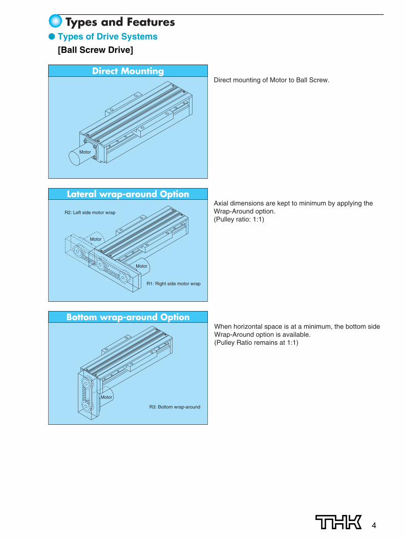
Direct Mounting
Lateral wrap-around Option
Bottom wrap-around Option
R2: Left side motor wrap
R1: Right side motor wrap
R3: Bottom wrap-around
Motor
Motor
Motor
Motor
Direct mounting of Motor to Ball Screw.
Axial dimensions are kept to minimum by applying the Wrap-Around option.(Pulley ratio: 1:1)
When horizontal space is at a minimum, the bottom side Wrap-Around option is available. (Pulley Ratio remains at 1:1)
● Types of Drive Systems
[Ball Screw Drive]

Horizontal Mounting
Timing pulley
Note 1: When mounting the GL-N to a vertical surface in a horizontal mode, the timing belt may sag or bow. This must be taken into consideration as the belt may tend to rub in the flange/pulley area.
Note 2: The GL-N model cannot be used in a vertical position for the timing belt type.
5
[Timing Belt Type]
● Specification
Figure 6
Model number GL15N GL20N
Drive system Ball Screw Belt Ball Screw Belt
Screw lead (mm) 5, 10, 16, 20, 30 — 5, 10, 20, 40 —
Pulley pitch diameter (mm) — 35.01 — 38.20
Repeatability Note 1) (mm) ±0.02 ±0.08 ±0.02 ±0.08
Effective stroke Note 2)
(mm) 100 to 1200 50 to 1700 200 to 1550 150 to 2700
Applicable LM Guide SSR15V SSR15W SHS15V SSR15V SSR15W SHS15V SSR20V SSR20W SHS20V SSR20V SSR20W SHS20V
Note 3)
MA 84.3 98.2 157.5 112.1 130.7 210.4 165.9 242.5 336.8 150.2 238.1 329.4
Rated moment load MB (N-m) 64.5 77.5 154.4 86.4 103.8 206.2 122.5 179.5 327.8 110.9 176.7 318.6
MC 75.7 113.1 204.1 108.0 164.8 296.2 128.3 187.5 371.2 123.8 199.3 346.0
Note 1: This repeatability is ensured at an ambient temperature of 20°C.Note 2: The effective stroke decreases depending on the table length. See the dimensional drawings for stroke details.Note 3: The rated moment load refers to the moment in each direction obtained when the life travel distance of the LM guide is 5000km. For
the ball screw drive, the rated moment load is the minimum loaded moment calculated under the conditions of the maximum moving speed per lead and an acceleration of 0.3G.
6
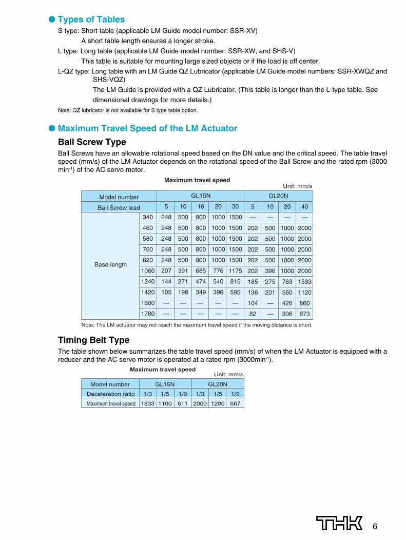
● Types of TablesS type: Short table (applicable LM Guide model number: SSR-XV)
A short table length ensures a longer stroke.
L type: Long table (applicable LM Guide model number: SSR-XW, and SHS-V)
This table is suitable for mounting large sized objects or if the load is off center.
L-QZ type: Long table with an LM Guide QZ Lubricator (applicable LM Guide model numbers: SSR-XWQZ andSHS-VQZ)
The LM Guide is provided with a QZ Lubricator. (This table is longer than the L-type table. See
dimensional drawings for more details.)
Note: QZ lubricator is not available for S type table option.
● Maximum Travel Speed of the LM Actuator
Ball Screw TypeBall Screws have an allowable rotational speed based on the DN value and the critical speed. The table travelspeed (mm/s) of the LM Actuator depends on the rotational speed of the Ball Screw and the rated rpm (3000min-1) of the AC servo motor.
Timing Belt TypeThe table shown below summarizes the table travel speed (mm/s) of when the LM Actuator is equipped with areducer and the AC servo motor is operated at a rated rpm (3000min-1).
Model number
Ball Screw lead
Maximum travel speedUnit: mm/s
GL15N
5 10 16 20 30
248 500 800 1000 1500
248 500 800 1000 1500
248 500 800 1000 1500
248 500 800 1000 1500
248 500 800 1000 1500
207 391 685 776 1175
144 271 474 540 815
105 198 349 396 595
— — — — —
— — — — —
GL20N
5 10 20 40
— — — —
202 500 1000 2000
202 500 1000 2000
202 500 1000 2000
202 500 1000 2000
202 396 1000 2000
185 275 763 1533
136 201 560 1120
104 — 426 860
82 — 336 673
340
460
580
700
820
1060
1240
1420
1600
1780
Base length
Note: The LM actuator may not reach the maximum travel speed if the moving distance is short.
Model number GL15N GL20N
Deceleration ratio 1/3 1/5 1/9 1/3 1/5 1/9
Maximum travel speed 1833 1100 611 2000 1200 667
Maximum travel speedUnit: mm/s

7
Nominal Model Numbers
Nominal model number GL15N/GL20N
Base length Example) For 340 mm: 034 Standard base lengths shown on page 8 to 15
LM Guide SV: SSR-XV (S-type table) SW: SSR-XW (L-type table)HV: SHS-V (L-type table) (L-QZ type table for SSR/SHS with QZ)
LM Guide QZ Lubricator No mark: Not provided with QZ Q: Provided with QZ (SSR-XW/SHS only)
Driving system �Ball Screw-driven B05: Ball Screw lead 5 mm (GL15/20) B20: Ball Screw lead 20 mm (GL15) B20: Ball Screw lead 20 mm (GL20) B10: Ball Screw lead 10 mm (GL15/20) B30: Ball Screw lead 30 mm (GL15 only) B16: Ball Screw lead 16 mm (G15 only) B40: Ball Screw lead 40 mm (GL20 only)
�Belt-driven EH: Horizontal model specification
Ball Screw QZ Lubricator No mark: Not provided with QZ Q: Provided with QZ (SSR-XW/SHS only)
No mark: Direct mounting R1: Right side motor wrapR2: Left side motor wrapR3: Bottom
�Ball Screw specification for direct motor connectionA: inner diameter 30H7, M4, PCD46 F: inner diameter 50H7, M4, PCD70B: inner diameter 50H7, M5, PCD70 G: inner diameter 34H7, M3, PCD48C: inner diameter 50H7, M4, PCD60 H: inner diameter 36H7, M4, mounting aperture pitch 50D: inner diameter 70H7, M5, PCD90 (GL20 only)I: inner diameter 60H7, M6, mounting aperture pitch 70 (GL20 only)E: inner diameter 30H7, M3, PCD45 J: inner diameter 70H7, M6, PCD90 (GL20 only)T: inner diameter 22, counter bore for M3 from rear, mounting pitch 31 (NEMA17 standard) (GL15 only)U: inner diameter 38.1, M4, mounting pitch 47.14 (NEMA23 standard)V: inner diameter 73.03, M5, mounting pitch 69.6 (NEMA34 standard) (GL20 only)W: inner diameter 40, M5, PCD63 Z: inner diameter 60, M5, PCD75
�Ball Screw specification for motor wrap-aroundB14: inner diameter 50, M5, PCD70, pulley inner diameter 14 F11: inner diameter 50, M4, PCD70, pulley inner diameter 11D11: inner diameter 70, M5, PCD90, pulley inner diameter 11 F14: inner diameter 50, M4, PCD70, pulley inner diameter 14D14: inner diameter 70, M5, PCD90, pulley inner diameter 14 J14: inner diameter 70, M6, PCD90, pulley inner diameter 14U11: inner diameter 38.1, M4, mounting pitch 47.14, pulley inner diameter 6.35 mm (NEMA23 standard)V11: inner diameter 73.03, M5, mounting pitch 69.6, pulley inner diameter 9.35 mm (NEMA34 standard) (GL20 only)
�Belt specification for motor bracketN: No motor bracketB1: inner diameter 50, 5.5, PCD60 U1: inner diameter 38.1, M4 (NEMA23 standard)B2: inner diameter 60, 6.5, PCD90 V1: inner diameter 73.03, M5 (NEMA34 standard) (GL20 only)
�Reducer specification for belt drive (motor bracket, only available for B1 and B2) Reducer symbols: G1, G2, G3, G4, G5, G6, G7, G8 and G9 (See page 20 for details of the reducer symbols and available motors.)
Note: When ordering a belt drive with reducer inform us of the model number of the motor to which it is to be attached. (Please indicate combined motor for selecting gear head interface.)
No mark: Not provided with reducer.
Reduction ratio: 03: 1/3 05: 1/5 09: 1/9Note: Model number display example: B1-G1-03 (motor bracket B1 + reducer G1 + reduction ratio 1/3)
No mark: Not provided with reducer.
Covers and bellows N: Not provided C: Cover provided J: Bellow provided
Sensors N: None A: Photo sensor EE-SX-671 (3 pcs) B: Photo sensor EE-SX-674 (3 pcs)C1: Proximity sensor TL-W3MC1 (N.O.×3)C2: Proximity sensor TL-W3MC1 (N.O.×1), TL-W3MC2 (N.C.×2)C3: TL-W3MB1(N.O.×3)C4: TL-W3MB1(N.O.×1), TL-W3MB2(N.C.×2)
Cable carrier N: None A: TKP0180-2B-R28 (Tsubakimoto Chain Co.) F: TKP0320-2B-R75 (Tsubakimoto Chain Co.) B: TKP0180-2B-R37 (Tsubakimoto Chain Co.) G: TKP0320-3B-R37 (Tsubakimoto Chain Co.) C: TKP0180-2B-R50 (Tsubakimoto Chain Co.) H: TKP0320-3B-R50 (Tsubakimoto Chain Co.) D: TKP0320-2B-R37 (Tsubakimoto Chain Co.) I: TKP0320-3B-R75 (Tsubakimoto Chain Co.) E: TKP0320-2B-R50 (Tsubakimoto Chain Co.)
Mounting hole Y: Standard mounting counter bore
1
2
3
4
5
6
7
8
11
12
9
10
13
14
Ball Screw driveEnd plate type
Ball Screw drivenmotor mount method
GL20N—070—SW Q—B20 Q R1—B14—C—A—J—Y1 2 3 4 5 6 7 8 11 12 13 14
Ball Screw type specification
GL20N—070—SW Q—EH—B1—G1—03—C—A—J—Y1 2 3 4 5 8 9 10 11 12 13 14
Belt type specification
Timing belt driveMotor bracket type
Reducer
Reduction ratio
*Ball Screw leads (30 mm and 40 mm) are excluded for wiper rings.
Items with cyan marker indicate standard options at this time.

8
Dimensional Drawing
● GL15N Model, Ball Screw Driven
[Direct Mounting Specification]
4
4
4
4
A
View of A
Detailed view of B Detailed view of C
2-M3 depth 6
59.1
Mechanical stroke/2 Mechanical stroke/2Table length: ad
12Base length: L12
(25)
b 10
75.6
116
23.6
236
154
90
B
C
6
7
11
54
1
11
4.3
5.8
2.5 1.5
0.51
4-M6 THRU with thread inserts 2D
140
c
15
( 25 )
( g )n�150
2�(n+1)C-Bore For M6150
35
50
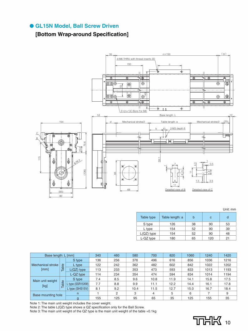
Table type Table length: a b c d
S type 126 38 90 53L type 154 52 90 39
L(QZ) type 154 52 90 48L-QZ type 180 65 120 21
Unit: mm
Base length: L [mm] 340 460 580 700 820 1060 1240 1420S type 136 256 376 496 616 856 1036 1216
Mechanical stroke L type 122 242 362 482 602 842 1022 1202[mm] L(QZ) type 113 233 353 473 593 833 1013 1193
L-QZ type 114 234 354 474 594 834 1014 1194
Main unit weight S type 5.8 6.9 8.0 9.2 10.3 12.5 14.2 15.9
[kg]L type (SSR15XW) 6.1 7.2 8.3 9.5 10.6 12.8 14.5 16.2L type (SHS15V) 6.5 7.6 8.8 9.9 11.1 13.4 15.1 16.8
Base mounting hole n 1 2 3 4 5 6 7 9g 155 125 95 65 35 125 155 35
Tabl
eTa
ble
Note 1: The main unit weight includes the cover weight.Note 2: The table L(QZ) type shows a QZ specification only for the Ball Screw.Note 3: The main unit weight of the QZ type is the main unit weight of the table +0.1kg.

9
● GL15N Model, Ball Screw Driven
[Lateral Wrap-around Specification]
Base length: L [mm] 340 460 580 700 820 1060 1240 1420S type 136 256 376 496 616 856 1036 1216
Mechanical stroke L type 122 242 362 482 602 842 1022 1202[mm] L(QZ) type 113 233 353 473 593 833 1013 1193
L-QZ type 114 234 354 474 594 834 1014 1194
Main unit weight S type 7.4 8.5 9.6 10.8 11.9 14.1 15.8 17.5
[kg]L type (SSR15XW) 7.7 8.8 9.9 11.1 12.2 14.4 16.1 17.8L type (SHS15V) 8.1 9.2 10.4 11.5 12.7 15.0 16.7 18.4
Base mounting hole n 1 2 3 4 5 6 7 9g 155 125 95 65 35 125 155 35
Tabl
eTa
ble
Note 1: The main unit weight includes the cover weight.Note 2: The table L(QZ) type shows a QZ specification only for the Ball Screw.Note 3: The main unit weight of the QZ type is the main unit weight of the table +0.1kg
Table type Table length: a b c d
S type 126 38 90 53L type 154 52 90 39
L(QZ) type 154 52 90 48L-QZ type 180 65 120 21
Unit: mm
Detailed view of B Detailed view of C
6 711
54
1
b
90116
59.1
d Mechanical stroke/2Table length: a (25)
12Base length: L
2-M3 depth 6
Mechanical stroke/2
10
75.615
4
34.319.9
3.7
255
53
140
(70.6)
B C
11
4.3
5.8
2.5
1.5
0.5
1
68
94
4-M6 THRU with thread inserts 2D
140
c
2�(n+1)C-Bore For M6
150
n�15035 ( g )
50
10
● GL15N Model, Ball Screw Driven
[Bottom Wrap-around Specification]
Detailed view of B Detailed view of C
6
7
115
4
1
11
4.3
5.8
2.51.5
0.5
B
C
68
94
59.1
Table length: ad Mechanical stroke/2 (25)
b
Mechanical stroke/2
2-M3 depth 610
23.6
(136
)
115
154
(85)
Base length: L53 12
75.6
90
1
6
6
6
6
44
4
44
4 44
44 44
c
140
4-M6 THRU with thread inserts 2D
2�(n+1)C-Bore For M6
150
50
35 n�150 ( g )
44
Base length: L [mm] 340 460 580 700 820 1060 1240 1420S type 136 256 376 496 616 856 1036 1216
Mechanical stroke L type 122 242 362 482 602 842 1022 1202[mm] L(QZ) type 113 233 353 473 593 833 1013 1193
L-QZ type 114 234 354 474 594 834 1014 1194
Main unit weight S type 7.4 8.5 9.6 10.8 11.9 14.1 15.8 17.5
[kg]L type (SSR15XW) 7.7 8.8 9.9 11.1 12.2 14.4 16.1 17.8L type (SHS15V) 8.1 9.2 10.4 11.5 12.7 15.0 16.7 18.4
Base mounting hole n 1 2 3 4 5 6 7 9g 155 125 95 65 35 125 155 35
Tabl
eTa
ble
Note 1: The main unit weight includes the cover weight.Note 2: The table L(QZ) type shows a QZ specification only for the Ball Screw.Note 3: The main unit weight of the QZ type is the main unit weight of the table +0.1kg
Table type Table length: a b c d
S type 126 38 90 53L type 154 52 90 39
L(QZ) type 154 52 90 48L-QZ type 180 65 120 21
Unit: mm
11
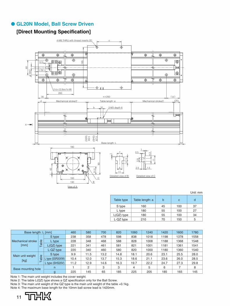
● GL20N Model, Ball Screw Driven
[Direct Mounting Specification]
Table type Table length: a b c d
S type 160 45 100 37L type 180 55 100 27
L(QZ) type 180 55 100 34L-QZ type 210 70 150 5
Unit: mm
Base length: L [mm] 460 580 700 820 1060 1240 1420 1600 1780S type 238 358 478 598 838 1018 1198 1378 1558
Mechanical stroke L type 228 348 468 588 828 1008 1188 1368 1548[mm] L(QZ) type 221 341 461 581 821 1001 1181 1361 1541
L-QZ type 220 340 460 580 820 1000 1180 1360 1540
Main unit weight S type 9.9 11.5 13.2 14.8 18.1 20.6 23.1 25.5 28.0
[kg]L type (SSR20XW) 10.4 12.0 13.7 15.3 18.6 21.1 23.6 26.0 28.5L type (SHS20V) 11.2 12.9 14.6 16.3 19.7 22.2 24.7 27.3 29.8
Base mounting hole n 1 2 3 3 4 5 6 7 8g 225 145 65 185 225 205 185 165 145
Tab
leT
able
Note 1: The main unit weight includes the cover weight.Note 2: The table L(QZ) type shows a QZ specification only for the Ball Screw.Note 3: The main unit weight of the QZ type is the main unit weight of the table +0.1kg.Note 4: The maximum base length for the 10mm ball screw lead is 1420mm.
A
View of A
Detailed view of CDetailed view of B
B
C
b 2-M3 depth 610
(25)Table length: a Mechanical stroke/2Mechanical stroke/2d
12 Base length: L 12
100
180
242
31.5
90
(SH
S)
67.5
(SS
R)
69.5
130
6
7
11
54
1
11
4.3
5.8
2.5 1.5
0.51
6
6
6
6
4-M8 THRU with thread inserts 2D c
16512.5
( 29 )
n�200
2�(n+1)C-Bore For M6
35
200
60
( g )
12
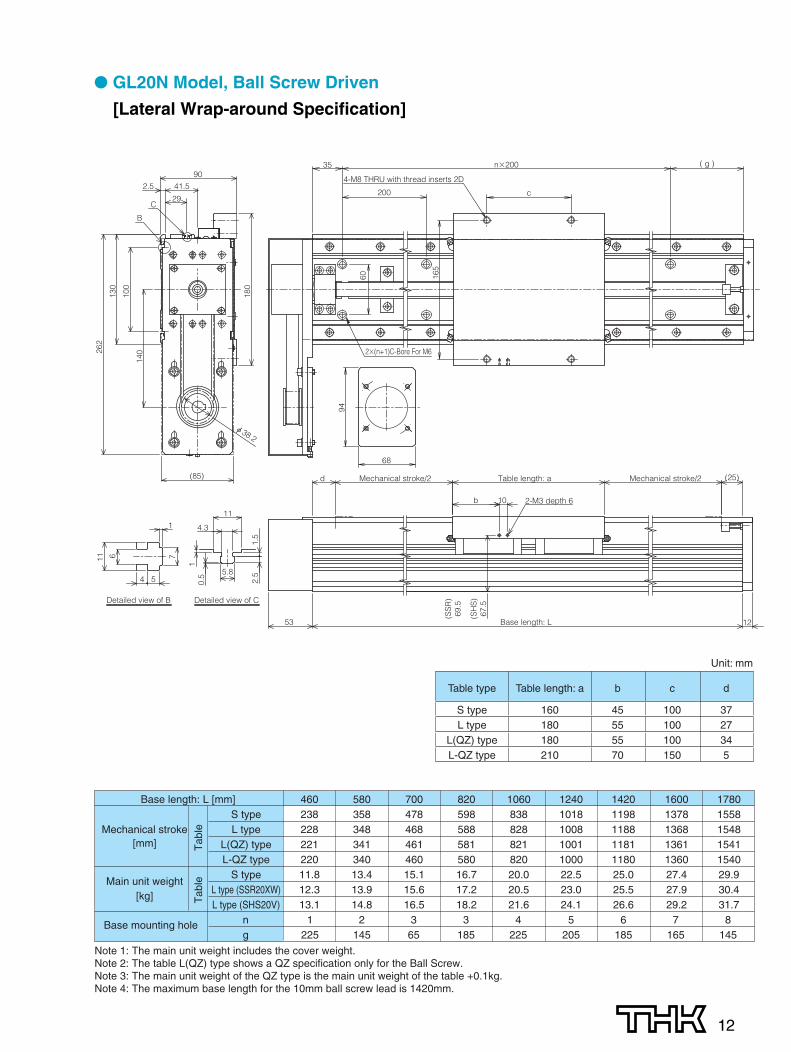
● GL20N Model, Ball Screw Driven
[Lateral Wrap-around Specification]
444
5
Detailed view of B
6 711
54
1
(85)
53
140
130
100
262
12Base length: L
180
d Table length: a (25)Mechanical stroke/2 Mechanical stroke/2
b 10 2-M3 depth 6
B
C
(SH
S)
67.5
(SS
R)
69.5
90
41.5
29
2.5
Detailed view of C
11
4.3
5.8
2.5
1.5
0.5
1c
68
165
94
4-M8 THRU with thread inserts 2D
200
35 n�200 ( g )
602�(n+1)C-Bore For M6
Base length: L [mm] 460 580 700 820 1060 1240 1420 1600 1780S type 238 358 478 598 838 1018 1198 1378 1558
Mechanical stroke L type 228 348 468 588 828 1008 1188 1368 1548[mm] L(QZ) type 221 341 461 581 821 1001 1181 1361 1541
L-QZ type 220 340 460 580 820 1000 1180 1360 1540
Main unit weightS type 11.8 13.4 15.1 16.7 20.0 22.5 25.0 27.4 29.9
[kg]L type (SSR20XW) 12.3 13.9 15.6 17.2 20.5 23.0 25.5 27.9 30.4L type (SHS20V) 13.1 14.8 16.5 18.2 21.6 24.1 26.6 29.2 31.7
Base mounting hole n 1 2 3 3 4 5 6 7 8g 225 145 65 185 225 205 185 165 145
Tab
leT
able
Note 1: The main unit weight includes the cover weight.Note 2: The table L(QZ) type shows a QZ specification only for the Ball Screw.Note 3: The main unit weight of the QZ type is the main unit weight of the table +0.1kg.Note 4: The maximum base length for the 10mm ball screw lead is 1420mm.
Table type Table length: a b c d
S type 160 45 100 37L type 180 55 100 27
L(QZ) type 180 55 100 34L-QZ type 210 70 150 5
Unit: mm
13
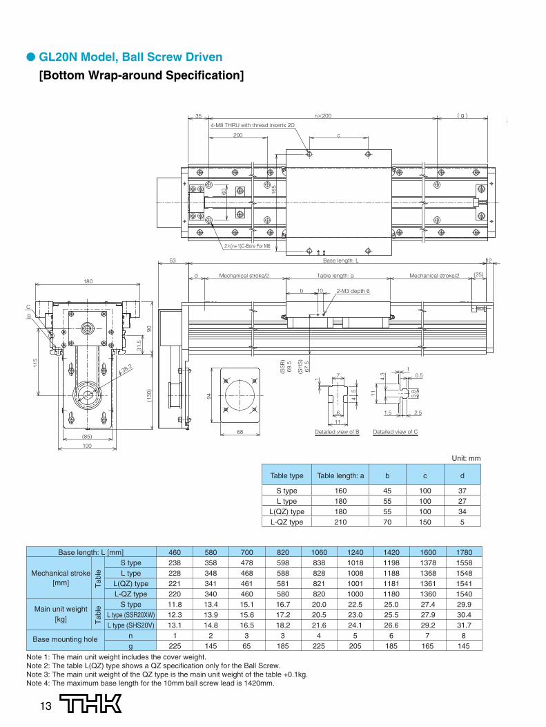
● GL20N Model, Ball Screw Driven
[Bottom Wrap-around Specification]
Detailed view of B Detailed view of C
4
4
5
6
7
11
54
1
11
4.3
5.8
2.51.5
0.5
B
C
100
Mechanical stroke/2
10 2-M3 depth 6b
Table length: a
90
180
31.5
53
94
68
115
(85)
12Base length: L
Mechanical stroke/2 (25)d
(130
)
(SH
S)
67.5
(SS
R)
69.5
1
5 5
6
5
6
6
55
55
55
5 55
55
6
6
6 66
5
5 55 5
5
66
5 5
6
5
6
5
165
200
60
c
4-M8 THRU with thread inserts 2D
2�(n+1)C-Bore For M6
35 n�200 ( g )
Table type Table length: a b c d
S type 160 45 100 37L type 180 55 100 27
L(QZ) type 180 55 100 34L-QZ type 210 70 150 5
Unit: mm
Base length: L [mm] 460 580 700 820 1060 1240 1420 1600 1780S type 238 358 478 598 838 1018 1198 1378 1558
Mechanical stroke L type 228 348 468 588 828 1008 1188 1368 1548[mm] L(QZ) type 221 341 461 581 821 1001 1181 1361 1541
L-QZ type 220 340 460 580 820 1000 1180 1360 1540
Main unit weightS type 11.8 13.4 15.1 16.7 20.0 22.5 25.0 27.4 29.9
[kg]L type (SSR20XW) 12.3 13.9 15.6 17.2 20.5 23.0 25.5 27.9 30.4L type (SHS20V) 13.1 14.8 16.5 18.2 21.6 24.1 26.6 29.2 31.7
Base mounting hole n 1 2 3 3 4 5 6 7 8g 225 145 65 185 225 205 185 165 145
Tab
leT
able
Note 1: The main unit weight includes the cover weight.Note 2: The table L(QZ) type shows a QZ specification only for the Ball Screw.Note 3: The main unit weight of the QZ type is the main unit weight of the table +0.1kg.Note 4: The maximum base length for the 10mm ball screw lead is 1420mm.

14
● GL15N Model, Belt Driven
A
View of A
Detailed view of B Detailed view of C
B
C
6
7
11
54
1
11
4.3
5.8
2.5 1.5
0.5
b 1045°
PCD 76
66
75.6
45° 2-M3 depth 6
23.6
154
90
Mechanical stroke/2
59.1
Mechanical stroke/2 (105)Table length: a(15)
12Base length: L12(7.5
)
116
37
74
(40.
5)
4-M5 depth 8
1
1260
c
140
50
4-M6 THRU with thread inserts 2D
150
30 ( g )n�150
2�(n+1)C-Bore For M6
Table type Table length: a b c
S type 126 38 90L type 154 52 90
L-QZ type 180 65 120
Unit: mm
Base length: L [mm] 340 460 580 700 820 1060 1240 1420 1600 1780 1960
Mechanical strokeS type 94 214 334 454 574 814 994 1174 1354 1534 1714
[mm]L type 66 186 306 426 546 786 966 1146 1326 1506 1686
L-QZ type 40 160 280 400 520 760 940 1120 1300 1480 1660
Main unit weight S type 7.1 8.1 9.1 10.1 11.1 13.1 14.5 16.0 17.5 19.0 20.5
[kg]L type(SSR15XW) 7.4 8.4 9.4 10.4 11.4 13.4 14.8 16.3 17.8 19.3 20.8L type (SHS15V) 7.8 8.8 9.8 10.9 11.9 13.9 15.4 16.9 18.5 20.0 21.5
Base mounting hole n 1 2 3 3 4 6 7 8 9 11 12g 160 130 100 220 190 130 160 190 220 100 130
Tab
leT
able
Note 1: The main unit weight includes the cover weight.Note 2: The main unit weight of QZ type is the main unit weight of the table +0.1kg.
15
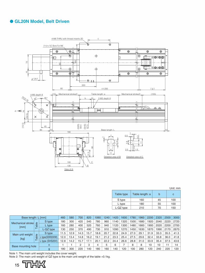
● GL20N Model, Belt Driven
A
View of A
Detailed view of B Detailed view of C
B
C
6
7
11
54
1
11
4.3
5.8
2.5 1.5
0.5
100
180
31.5
b 2-M3 depth 610
Table length: a Mechanical stroke/2Mechanical stroke/2 (105)90
(15)
12Base length: L12
PCD 76
80
(50.
5)
(12.
5)76
130
4-M5 depth 845°45°
40
(SH
S)
67.5
(SS
R)
69.5
1
5
5
5
5
65 5 6
655 6
5 55
55 55
55 55
5 55 5
5 55
55
4-M8 THRU with thread inserts 2D c
165
60
1572
2�(n+1)C-Bore For M6
200
80 ( g )n�200
Table type Table length: a b c
S type 160 45 100L type 180 55 100
L-QZ type 210 70 150
Unit: mm
Base length: L [mm]
Mechanical strokeS type
[mm]L type
L-QZ type
Main unit weight S type
[kg]L type(SSR20XW)L type (SHS20V)
Base mounting hole ng
460 580 700 820 1060 1240 1420 1600 1780 1960 2200 2320 2500 3000180 300 420 540 780 960 1140 1320 1500 1680 1920 2040 2220 2720160 280 400 520 760 940 1120 1300 1480 1660 1900 2020 2200 2700130 250 370 490 730 910 1090 1270 1450 1630 1870 1990 2170 267011.5 12.9 14.3 15.7 18.6 20.7 22.8 24.9 27.0 29.1 31.9 33.3 35.5 41.312.0 13.4 14.8 16.2 19.1 21.2 23.3 25.4 27.5 29.6 32.4 33.8 36.0 41.812.8 14.2 15.7 17.1 20.1 22.2 24.4 26.6 28.8 31.0 33.9 35.4 37.5 43.6
1 1 2 3 4 5 6 7 8 8 10 10 11 14180 300 220 140 180 160 140 120 100 280 120 240 220 120
Tab
leT
able
Note 1: The main unit weight includes the cover weight.Note 2: The main unit weight of QZ type is the main unit weight of the table +0.1kg.
16
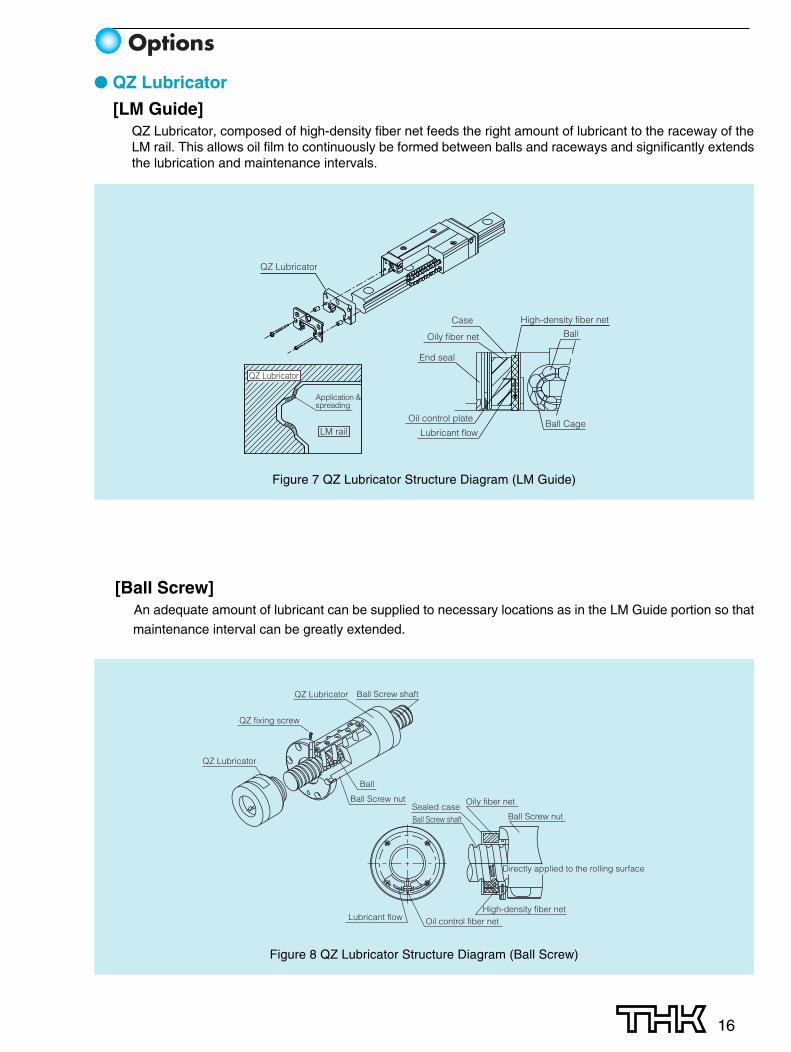
Options
● QZ Lubricator
[LM Guide]QZ Lubricator, composed of high-density fiber net feeds the right amount of lubricant to the raceway of theLM rail. This allows oil film to continuously be formed between balls and raceways and significantly extendsthe lubrication and maintenance intervals.
Figure 7 QZ Lubricator Structure Diagram (LM Guide)
QZ Lubricator
LM rail
Application &spreading
End seal
Lubricant flow
Oil control plateBall Cage
BallCase High-density fiber net
Oily fiber net
QZ Lubricator
[Ball Screw]An adequate amount of lubricant can be supplied to necessary locations as in the LM Guide portion so that
maintenance interval can be greatly extended.
Figure 8 QZ Lubricator Structure Diagram (Ball Screw)
Lubricant flow Oil control fiber netHigh-density fiber net
Oily fiber net
Directly applied to the rolling surface
Ball Screw shaftSealed case
Ball Screw nut
QZ Lubricator
QZ Lubricator
QZ fixing screw
Ball Screw shaft
Ball
Ball Screw nut

17
● Motor Bracket (Ball Screw Type Specification)
[Control Number]Motor brackets are available to mount various types of motors. The following table lists by model number themotor brackets available for motors. When purchasing a motor bracket, specify the corresponding modelnumber.
Motor GL15N GL20N
SGMJV-01100W �40
A — A —SGMAV-01 A — A —SGMJV-02
200WB B14 B B14
SGMAV-02�60
B B14 B B14SGMJV-04
400W— — B B14
SGMAV-04 — — B B14SGMAS-01
100W�40 A — A —
SGMPS-01 B — B —SGMAS-02 200W �60 B B14 B B14SGMAS-04 400W — — B B14SGMPS-02 200W
�80— — J J14
SGMPS-04 400W — — J J14SGMAH-01
100W�40 A — A —
SGMPH-01 B — B —SGMAH-02 200W �60 B B14 B B14SGMAH-04 400W — — B B14SGMPH-02 200W
�80— — J J14
SGMPH-04 400W — — J J14HF-MP13
100W �40A — A —
HF-KP13 A — A —HF-MP23
200WB B14 B B14
HF-KP23�60
B B14 B B14HF-MP43
400W— — B B14
HF-KP43 — — B B14HC-MFS13
100W �40A — A —
HC-KFS13 A — A —HC-MFS23
200WB B14 B B14
HC-KFS23�60
B B14 B B14HC-MFS43
400W— — B B14
HC-KFS43 — — B B14MSMD01
100W�38 E — E —
MQMA01 F — F —MSMD02 200W �60 F F11 F F11MSMD04 400W — — F F14MQMA02 200W
�80— — D D11
MQMA04 400W — — D D14MSMA01
100W�38 E — E —
MQMA01 F — F —MSMA02 200W �60 F F11 F F11MSMA04 400W — — F F14MQMA02 200W
�80— — D D11
MQMA04 400W — — D D14R88M-U10030
�40A — A —
R88M-W10030 100W A — A —R88M-WP10030 B — B —R88M-U20030
200WB B14 B B14
R88M-W20030 �60 B B14 B B14R88M-U40030
400W— — B B14
R88M-W40030 — — B B14R88M-WP20030 200W
�80— — J —
R88M-WP40030 400W — — J —� 0.3/5000is 100W
�40A — A —
� 0.4/5000is 125W B — B —� 0.5/5000is 200W
�60B B9 B B9
� 1/5000is 400W — — B B14Q1AA04010D 100W �40 A — A —Q1AA06020D 200W
�60B B14 B B14
Q1AA06040D 400W — — B B14A1510V 160W W — W —A1520U 270W �55 W — W —A1530U 390W — — W —A210V 370W
�70— — Z —
A220T 620W — — Z —RK564 H — H —RK566 �60 H — H —RK569 H — H —RK596
— �85— — I —
RK599 — — I —AS66
�60H — H —
ASC66 H — H —AS98 �85 — — I —
Manufacturer Series Model number Flange angle Wrap-around Wrap-around
AC
Ser
vo m
otor
Ste
ppin
g m
otor
J2-Super
J3
MELSERVO
� step
SANMOTION Q1
MPL
� is series
OMNUC W
MINAS A4
MINAS A
∑-5
∑-3
∑-2
Mitsubishi ElectricCorporation
Matsushita Electricindustrial Co., Ltd.
OMRON Corporation
FANUC
Sanyo Denki Co.,Ltd.
Allen-Bradley
ORIENTAL MOTORCo.,Ltd.
YASKAWA ElectricCorporation
5-phase RK
Table 4 Motors and Applicable motor Brackets
Direct motormounting
Direct motormounting
NEMA 17 Standard motorNEMA 23 Standard motorNEMA 34 Standard motor
�42 T — — —�56 U U11 U U11�85 — — V V11
Ratedoutput
Note: A motor shaft for motor wrap option will need a key.
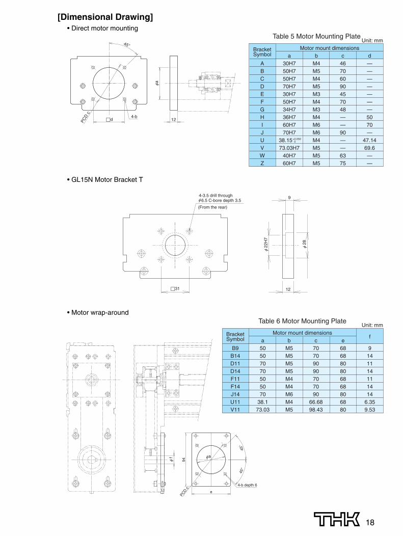
18
[Dimensional Drawing]• Direct motor mounting
Bracket Motor mount dimensionsSymbol a b c d
A 30H7 M4 46 —B 50H7 M5 70 —C 50H7 M4 60 —D 70H7 M5 90 —E 30H7 M3 45 —F 50H7 M4 70 —G 34H7 M3 48 —H 36H7 M4 — 50I 60H7 M6 — 70J 70H7 M6 90 —U 38.15 M4 — 47.14V 73.03H7 M5 — 69.6W 40H7 M5 63 —Z 60H7 M5 75 —
Table 5 Motor Mounting PlateUnit: mm
+0.050 0
�d 12
45°
PCD
c
4-b
• GL15N Motor Bracket T
Bracket Motor mount dimensionsfSymbol a b c e
B9 50 M5 70 68 9B14 50 M5 70 68 14D11 70 M5 90 80 11D14 70 M5 90 80 14F11 50 M4 70 68 11F14 50 M4 70 68 14J14 70 M6 90 80 14U11 38.1 M4 66.68 68 6.35V11 73.03 M5 98.43 80 9.53
Table 6 Motor Mounting PlateUnit: mm
• Motor wrap-around
5
44 4
45°
e
45°
94PC
D c
4-b depth 6
�31
9
12
4-3.5 drill through 6.5 C-bore depth 3.5
(From the rear)
19
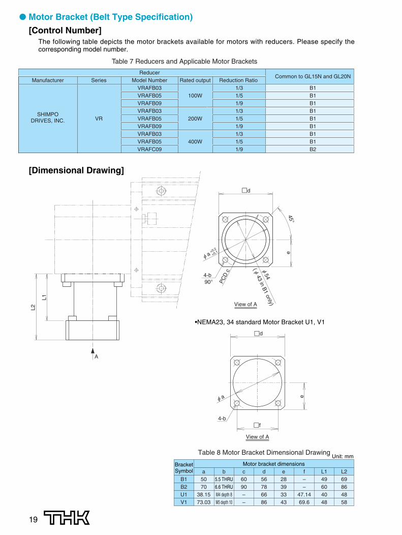
● Motor Bracket (Belt Type Specification)
[Control Number]The following table depicts the motor brackets available for motors with reducers. Please specify thecorresponding model number.
Table 7 Reducers and Applicable Motor Brackets
ReducerCommon to GL15N and GL20N
Manufacturer Series Model Number Rated output Reduction Ratio VRAFB03 1/3 B1VRAFB05 100W 1/5 B1VRAFB09 1/9 B1
SHIMPOVRAFB03 1/3 B1
DRIVES, INC. VR VRAFB05 200W 1/5 B1VRAFB09 1/9 B1VRAFB03 1/3 B1VRAFB05 400W 1/5 B1VRAFC09 1/9 B2
[Dimensional Drawing]
Bracket Motor bracket dimensionsSymbol a b c d e f L1 L2
B1 50 5.5 THRU 60 56 28 – 49 69B2 70 6.6 THRU 90 78 39 – 60 86U1 38.15 M4 depth 8 – 66 33 47.14 40 48V1 73.03 M5 depth 10 – 86 43 69.6 48 58
Table 8 Motor Bracket Dimensional DrawingUnit: mm
�d
e
45°
A
L2
L1
+0.2
+0.1
PC
D c
4-b90°
( 43 in B1 only)View of A
•NEMA23, 34 standard Motor Bracket U1, V1
�d
4-b
View of A
�f
e
20
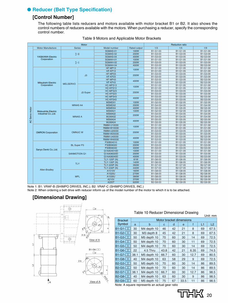
● Reducer (Belt Type Specification)
[Control Number]The following table lists reducers and motors available with motor bracket B1 or B2. It also shows thecontrol numbers of reducers available with the motors. When purchasing a reducer, specify the correspondingcontrol number.
Motor Reduction ratioMotor Manufacture Series Model number Rated output 1/3 1/5 1/9
SGMAS-01 100W B1-G1-03 B1-G1-05 B1-G1-09∑-3 SGMAS-02 200W B1-G3-03 B1-G3-05 B1-G3-09
SGMAS-04 400W B1-G3-03 B1-G3-05 B2-G3-09SGMAH-01 100W B1-G1-03 B1-G1-05 B1-G1-09
∑-2 SGMAH-02 200W B1-G3-03 B1-G3-05 B1-G3-09SGMAH-04 400W B1-G3-03 B1-G3-05 B2-G3-09HF-MP13
100WB1-G1-03 B1-G1-05 B1-G1-09
HF-KP13 B1-G1-03 B1-G1-05 B1-G1-09HF-MP23
200WB1-G3-03 B1-G3-05 B1-G3-09
HF-KP23 B1-G3-03 B1-G3-05 B1-G3-09HF-MP43
400WB1-G3-03 B1-G3-05 B2-G3-09
HF-KP43 B1-G3-03 B1-G3-05 B2-G3-09HC-MFS13
100WB1-G1-03 B1-G1-05 B1-G1-09
HC-KFS13 B1-G1-03 B1-G1-05 B1-G1-09HC-MFS23
200WB1-G3-03 B1-G3-05 B1-G3-09
HC-KFS23 B1-G3-03 B1-G3-05 B1-G3-09HC-MFS43
400WB1-G3-03 B1-G3-05 B2-G3-09
HC-KFS43 B1-G3-03 B1-G3-05 B2-G3-09MSMD01 100W B1-G2-03 B1-G2-05 B1-G2-09
MINAS A4 MSMD02 200W B1-G4-03 B1-G4-05 B1-G4-09MSMD04 400W B1-G5-03 B1-G5-05 B2-G5-09MSMA01 100W B1-G2-03 B1-G2-05 B1-G2-09MSMA02
200WB1-G4-03 B1-G4-05 B1-G4-09
MINAS A MUMA02 B1-G4-03 B1-G4-05 B1-G4-09MSMA04
400WB1-G5-03 B1-G5-05 B2-G5-09
MUMA04 B1-G5-03 B1-G5-05 B2-G5-09R88M-U10030
100WB1-G1-03 B1-G1-05 B1-G1-09
R88M-W10030 B1-G1-03 B1-G1-05 B1-G1-09
OMNUC WR88M-U20030
200WB1-G3-03 B1-G3-05 B1-G3-09
R88M-W20030 B1-G3-03 B1-G3-05 B1-G3-09R88M-U40030
400WB1-G3-03 B1-G3-05 B2-G3-09
R88M-W40030 B1-G3-03 B1-G3-05 B2-G3-09P30B04010 100W B1-G1-03 B1-G1-05 B1-G1-09
BL Super P3 P30B06020 200W B1-G3-03 B1-G3-05 B1-G3-09P30B06040 400W B1-G3-03 B1-G3-05 B2-G3-09
Q1AA04010D 100W B1-G1-03 B1-G1-05 B1-G1-09SANMOTION Q1 Q1AA06020D 200W B1-G3-03 B1-G3-05 B1-G3-09
Q1AA06040D 400W B1-G3-03 B1-G3-05 B2-G3-09TLY-120P (N) 81W B1-G6-03 B1-G6-05 B1-G6-09
TLYTLY-130P (N) 140W B1-G6-03 B1-G6-05 B1-G6-09TLY-220P (N) 350W B1-G7-03 B1-G7-05 B2-G7-09TLY-230P (N) 440W B1-G7-03 B2-G7-05 B2-G7-09
Allen-Bradley A1510V 160W B1-G8-03 B1-G8-05 B1-G8-09A1520U 270W B1-G8-03 B1-G8-05 B2-G8-09
MPL A1530U 390W B1-G8-03 B1-G8-05 B2-G8-09A210V 370W B2-G9-03 B2-G9-05 B2-G9-09A220T 620W B2-G9-03 B2-G9-05 B2-G9-09
AC
Ser
vo m
otor
J3
J2-Super
MELSERVO
Table 9 Motors and Applicable Motor Brackets
Note 1: B1: VRAF-B (SHIMPO DRIVES, INC.); B2: VRAF-C (SHIMPO DRIVES, INC.)Note 2: When ordering a belt drive with reducer inform us of the model number of the motor to which it is to be attached.
YASKAWA ElectricCorporation
Matsushita Electricindustrial Co.,Ltd.
Mitsubishi ElectricCorporation
Sanyo Denki Co.,Ltd.
OMRON Corporation
[Dimensional Drawing]
Table 10 Reducer Dimensional DrawingUnit: mm
Bracket Motor bracket dimensionsSymbol a b c d e f L1 L2
B1-G1-�� 30 M4 depth 10 46 42 21 8 69 67.5B1-G2-�� 30 M3 depth 8 45 42 21 8 69 67.5B1-G3-�� 50 M5 depth 10 70 60 30 14 69 72.5B1-G4-�� 50 M4 depth 10 70 60 30 11 69 72.5B1-G5-�� 50 M4 depth 10 70 60 30 14 69 72.5B1-G6-�� 22 4.5 Thru 43.8 42 21 6.35 69 74.5B1-G7-�� 38.1 M5 depth 10 66.7 60 30 12.7 69 80.5B1-G8-�� 40 M4 depth 10 63 58 29 9 69 72.5B2-G3-�� 50 M5 depth 10 70 60 30 14 86 89.5B2-G5-�� 50 M4 depth 10 70 60 30 14 86 89.5B2-G7-�� 38.1 M4 depth 10 66.7 60 30 12.7 86 98.5B2-G8-�� 40 M4 depth 10 63 60 30 9 86 98.5B2-G9-�� 60 M5 depth 10 75 67 33.5 11 86 98.5Note: A square represents an actual gear ratio
A
L2L1
�d
e
PCD c
2-b
View of A
B1-G6-��
View of A
�d
e
45°
PCD
c4–b
21
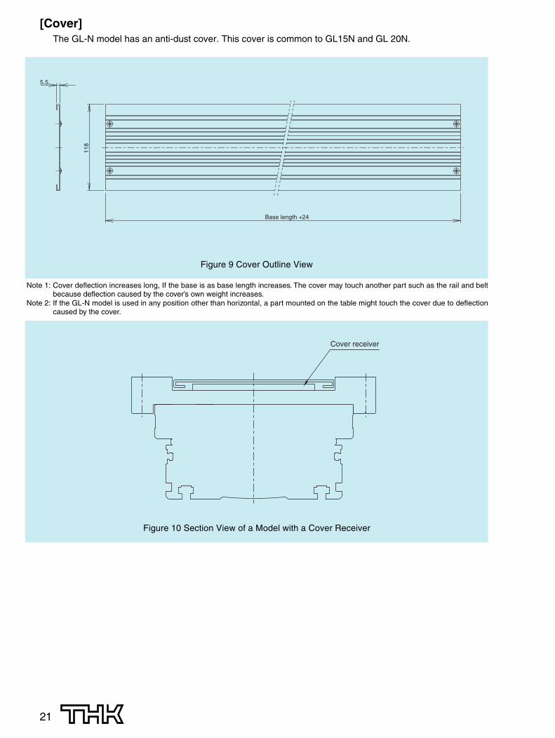
Figure 9 Cover Outline View
[Cover]The GL-N model has an anti-dust cover. This cover is common to GL15N and GL 20N.
5.511
8
Base length +24
Note 1: Cover deflection increases long, If the base is as base length increases. The cover may touch another part such as the rail and beltbecause deflection caused by the cover’s own weight increases.
Note 2: If the GL-N model is used in any position other than horizontal, a part mounted on the table might touch the cover due to deflectioncaused by the cover.
Figure 10 Section View of a Model with a Cover Receiver
Cover receiver
22
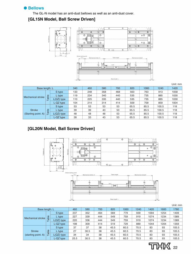
● BellowsThe GL-N model has an anti-dust bellows as well as an anti-dust cover.
[GL15N Model, Ball Screw Driven]
4
4
4
4
4
4
4
4
12 12
( A )Stroke starting point
Mechanical stroke / 2 Mechanical stroke/2Table length
Base length: L
40
73.6
153
(Bel
low
s)
154(
Tab
le)
2
55
5
5
6
5 55
6
5
5
6
5 5 5
6
5
5
6
66
55
6 6
66
5
5
5
5
5
6
5 55
12
( A )
12
Stroke starting point
Mechanical stroke / 2 Mechanical stroke/2Table length
Base length: L
89
45:SSR47:SHS
178(
Bel
low
s)
180(
Tab
le)
1
Base length: L 340 460 580 700 820 1060 1240 1420S type 133 248 358 468 563 763 913 1058
Mechanical strokeL type 119 234 340 440 535 735 885 1030
L(QZ) type 110 225 335 440 535 735 885 1030L-QZ type 104 214 314 414 509 709 859 1004
S type 53 53 53 53 65.5 85.5 100.5 118Stroke L type 39 39 43 53 65.5 85.5 100.5 118
(Starting point: A) L(QZ) type 48 48 48 53 65.5 85.5 100.5 118L-QZ type 28 33 43 53 65.5 85.5 100.5 118
Tab
leT
able
Unit: mm
Base length: L 460 580 700 820 1060 1240 1420 1600 1780S type 237 352 464 569 779 939 1094 1254 1409
Mechanical strokeL type 227 339 444 549 759 919 1074 1234 1389
L(QZ) type 220 336 444 549 759 919 1074 1234 1389L-QZ type 198 309 414 519 729 889 1044 1204 1359
S type 37 37 38 45.5 60.5 70.5 83 93 105.5Stroke L type 27 30.5 38 45.5 60.5 70.5 83 93 105.5
(starting point: A) L(QZ) type 34 34 38 45.5 60.5 70.5 83 93 105.5L-QZ type 25.5 30.5 38 45.5 60.5 70.5 83 93 105.5
Tab
leT
able
Unit: mm
[GL20N Model, Ball Screw Driven]
23
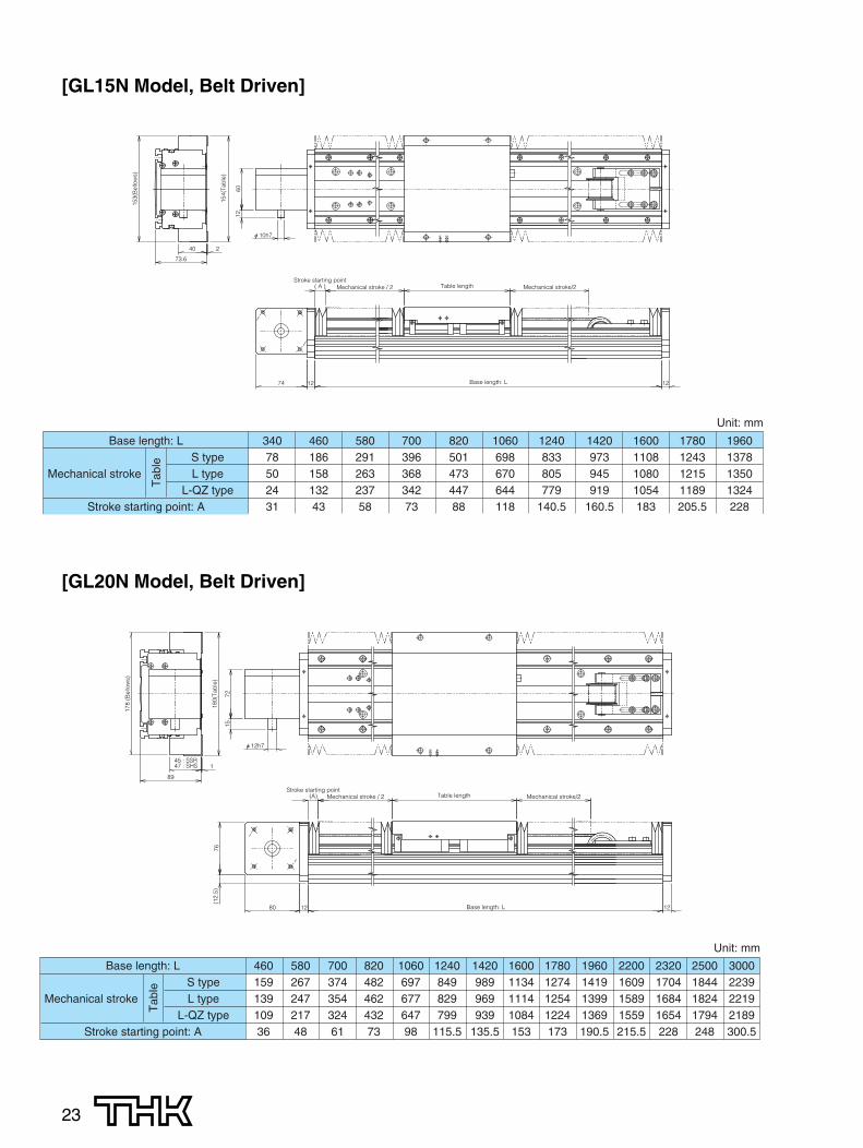
[GL15N Model, Belt Driven]
1260
74 12
Stroke starting point( A )
12
Mechanical stroke / 2 Mechanical stroke/2Table length
Base length: L
73.6
40
153(
Bel
low
s)
154(
Tab
le)
2
6
6
5
5
5
5
6
6
5
5
5
5
7215
(A)
1280
(12.
5)76
12
Mechanical stroke / 2 Table length
Base length: L
Mechanical stroke/2
89
45 : SSR47 : SHS
178
(Bel
low
s)
180(
Tab
le)
1
Stroke starting point
[GL20N Model, Belt Driven]
Base length: L 340 460 580 700 820 1060 1240 1420 1600 1780 1960S type 78 186 291 396 501 698 833 973 1108 1243 1378
Mechanical stroke L type 50 158 263 368 473 670 805 945 1080 1215 1350L-QZ type 24 132 237 342 447 644 779 919 1054 1189 1324
Stroke starting point: A 31 43 58 73 88 118 140.5 160.5 183 205.5 228
Tab
le
Unit: mm
Base length: LS type
Mechanical stroke L typeL-QZ type
Stroke starting point: A
460 580 700 820 1060 1240 1420 1600 1780 1960 2200 2320 2500 3000159 267 374 482 697 849 989 1134 1274 1419 1609 1704 1844 2239139 247 354 462 677 829 969 1114 1254 1399 1589 1684 1824 2219109 217 324 432 647 799 939 1084 1224 1369 1559 1654 1794 218936 48 61 73 98 115.5 135.5 153 173 190.5 215.5 228 248 300.5
Tab
le
Unit: mm
24
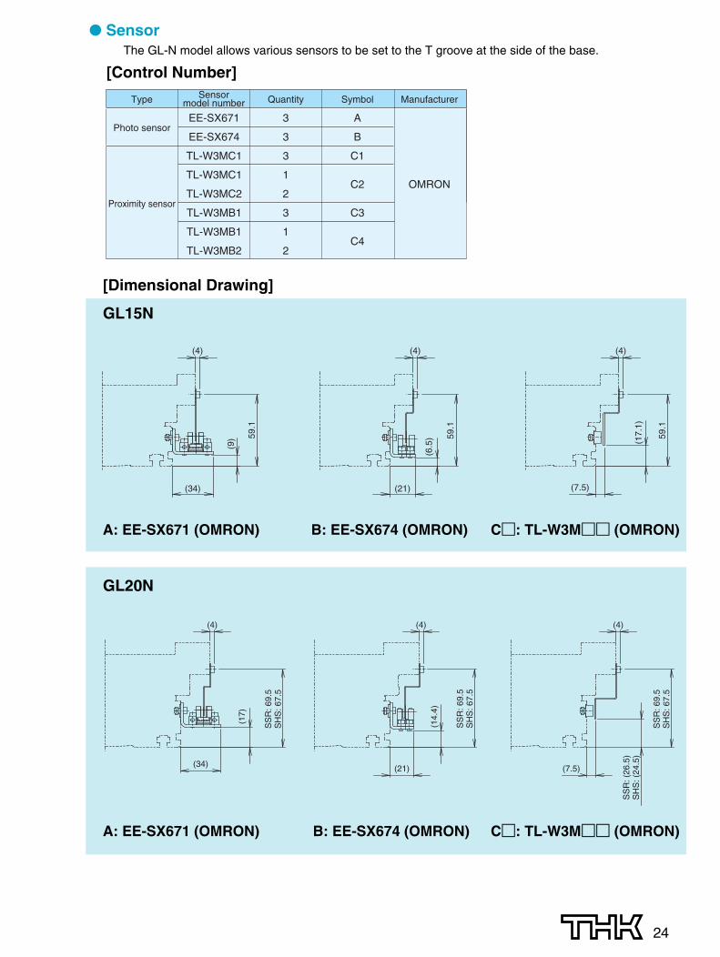
● SensorThe GL-N model allows various sensors to be set to the T groove at the side of the base.
[Control Number]Sensor
model numberType Quantity Symbol Manufacturer
Photo sensorEE-SX671 3 A
EE-SX674 3 B
TL-W3MC1 3 C1
TL-W3MC1 1C2 OMRON
Proximity sensorTL-W3MC2 2
TL-W3MB1 3 C3
TL-W3MB1 1C4
TL-W3MB2 2
[Dimensional Drawing]
GL15N
A: EE-SX671 (OMRON) B: EE-SX674 (OMRON) C�: TL-W3M�� (OMRON)
59.1
(7.5)
(4)
(17.
1)
59.1
(34)
(4)
(9)
(21)
(6.5
)
(4)
59.1
GL20N
(4) (4)
(7.5)(21)
(4)
(14.
4)
(34)
SS
R: 6
9.5
SH
S: 6
7.5
SS
R: (
26.5
)S
HS
: (24
.5)
SS
R: 6
9.5
SH
S: 6
7.5
(17)
SS
R: 6
9.5
SH
S: 6
7.5
A: EE-SX671 (OMRON) B: EE-SX674 (OMRON) C�: TL-W3M�� (OMRON)
25
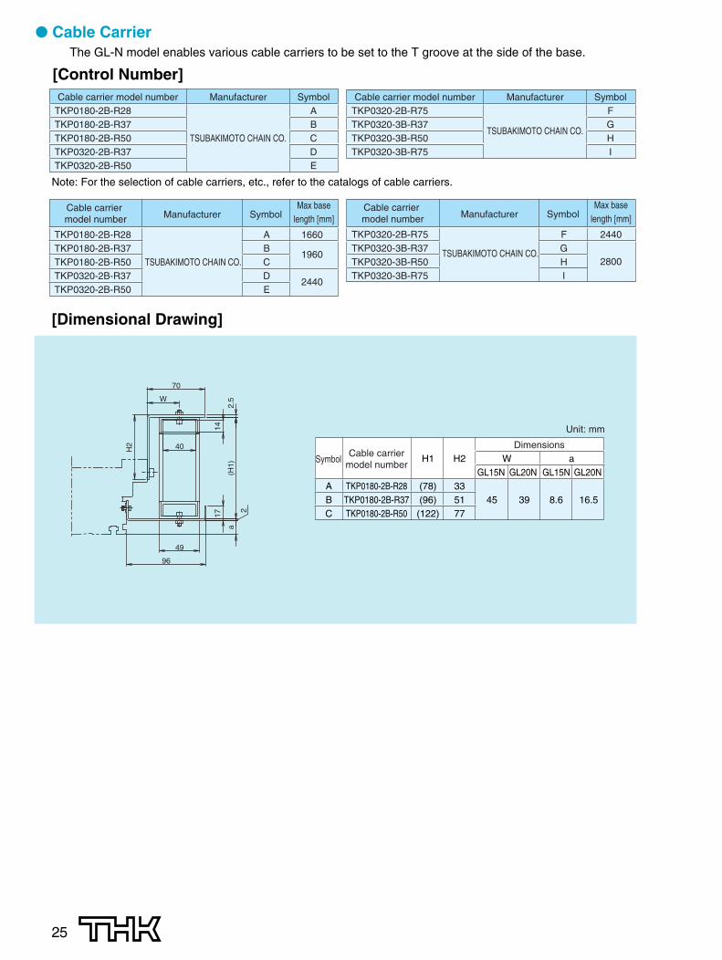
● Cable CarrierThe GL-N model enables various cable carriers to be set to the T groove at the side of the base.
[Control Number]Cable carrier model number Manufacturer Symbol
TKP0180-2B-R28 ATKP0180-2B-R37 BTKP0180-2B-R50 TSUBAKIMOTO CHAIN CO. CTKP0320-2B-R37 DTKP0320-2B-R50 E
Cable carrier model number Manufacturer SymbolTKP0320-2B-R75 FTKP0320-3B-R37 GTKP0320-3B-R50
TSUBAKIMOTO CHAIN CO.H
TKP0320-3B-R75 I
Note: For the selection of cable carriers, etc., refer to the catalogs of cable carriers.
TKP0180-2B-R28 A 1660TKP0180-2B-R37 B
1960TKP0180-2B-R50 TSUBAKIMOTO CHAIN CO. CTKP0320-2B-R37 D
2440TKP0320-2B-R50 E
Cable carrier model number Manufacturer Symbol
Max base length [mm]
TKP0320-2B-R75 F 2440TKP0320-3B-R37 G
2800TKP0320-3B-R50TSUBAKIMOTO CHAIN CO.
HTKP0320-3B-R75 I
Cable carrier model number Manufacturer Symbol
Max base length [mm]
DimensionsH1 H2 W a
GL15N GL20N GL15N GL20NA TKP0180-2B-R28 (78) 33B TKP0180-2B-R37 (96) 51 45 39 8.6 16.5C TKP0180-2B-R50 (122) 77
Unit: mm
SymbolCable carrier
model number
H2
17
(H1)
40
2
2.5
70
a
W
49
96
14
[Dimensional Drawing]

26
[Base-Mounting Fasteners]Base-mounting plate fasteners are available if they are necessary. Please contact THK for further details.
20
4
10.5
M5�0.8 THRU
Standard base length (mm)
Quantity
Quantity
Standard base length (mm)
340 460 580 700 820 1060 1240 1420
4 4 6 6 8 10 10 12
14 14 16 16 18 18 20
1600 1780 1960 2200 2320 2500 3000
(H1)
82
362.
5
2
17
W
24
a
56
19
H2
DimensionsH1 H2 W a
GL15N GL20N GL15N GL20ND TKP0320-2B-R37 (104) 59E TKP0320-2B-R50 (130) 85 38 32 8.6 16.5F TKP0320-2B-R75 (180) 135
Unit: mm
SymbolCable carrier
model number
DimensionsH1 H2 W a
GL15N GL20N GL15N GL20NG TKP0320-3B-R37 (104) 59H TKP0320-3B-R50 (130) 85 36.75 30.75 8.6 16.5I TKP0320-3B-R75 (180) 135
Unit: mm
SymbolCable carrier
model number
62
82
27W
H2
17
2
(H1)
2.5
108
19
50
a
27
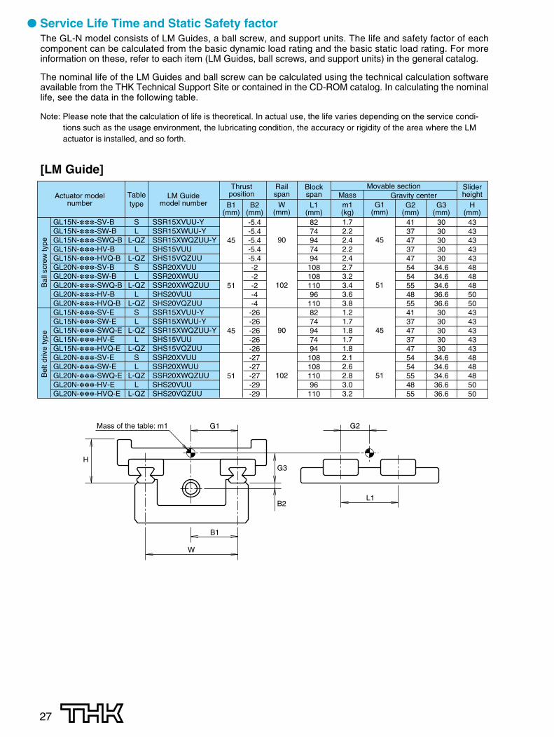
● Service Life Time and Static Safety factorThe GL-N model consists of LM Guides, a ball screw, and support units. The life and safety factor of eachcomponent can be calculated from the basic dynamic load rating and the basic static load rating. For moreinformation on these, refer to each item (LM Guides, ball screws, and support units) in the general catalog.
The nominal life of the LM Guides and ball screw can be calculated using the technical calculation softwareavailable from the THK Technical Support Site or contained in the CD-ROM catalog. In calculating the nominallife, see the data in the following table.
Note: Please note that the calculation of life is theoretical. In actual use, the life varies depending on the service condi-tions such as the usage environment, the lubricating condition, the accuracy or rigidity of the area where the LMactuator is installed, and so forth.
[LM Guide]
Actuator modelnumber
Bal
l scr
ew ty
peB
elt d
rive
type
GL15N-���-SV-BGL15N-���-SW-BGL15N-���-SWQ-BGL15N-���-HV-BGL15N-���-HVQ-BGL20N-���-SV-BGL20N-���-SW-BGL20N-���-SWQ-BGL20N-���-HV-BGL20N-���-HVQ-BGL15N-���-SV-EGL15N-���-SW-EGL15N-���-SWQ-EGL15N-���-HV-EGL15N-���-HVQ-EGL20N-���-SV-EGL20N-���-SW-EGL20N-���-SWQ-EGL20N-���-HV-EGL20N-���-HVQ-E
SL
L-QZL
L-QZSL
L-QZL
L-QZSL
L-QZL
L-QZSL
L-QZL
L-QZ
SSR15XVUU-YSSR15XWUU-YSSR15XWQZUU-YSHS15VUUSHS15VQZUUSSR20XVUUSSR20XWUUSSR20XWQZUUSHS20VUUSHS20VQZUUSSR15XVUU-YSSR15XWUU-YSSR15XWQZUU-YSHS15VUUSHS15VQZUUSSR20XVUUSSR20XWUUSSR20XWQZUUSHS20VUUSHS20VQZUU
LM Guidemodel number
Tabletype
Thrustposition
Movable sectionGravity center
B1(mm)
45
51
45
51
B2(mm)-5.4-5.4-5.4-5.4-5.4-2-2-2-4-4-26-26-26-26-26-27-27-27-29-29
Railspan
W(mm)
90
102
90
102
BlockspanL1
(mm)827494749410810811096110827494749410810811096110
Sliderheight
H(mm)
4343434343484848505043434343434848485050
Massm1(kg)1.72.22.42.22.42.73.23.43.63.81.21.71.81.71.82.12.62.83.03.2
G1(mm)
45
51
45
51
G2(mm)
4137473747545455485541374737475454554855
G3(mm)
3030303030
34.634.634.636.636.63030303030
34.634.634.636.636.6
L1
G2
W
B1
G1
HG3
B2
Mass of the table: m1

28
[Ball Screw]
Modelnumber
GL15N
GL15N
GL15N
GL15N
GL15N
GL20N
GL20N
GL20N
GL20N
Mountingmethod
Fixed–support
Fixed–support
Fixed–support
Fixed–support
Fixed–support
Fixed–support
Fixed–support
Fixed–support
Fixed–support
Mounting distanceMAX (mm)
1861266179
1259176
1256179
1259179
1259299
1619299
1259297
1617297
1617
Category
Rolled–without pre-load
Rolled–without pre-load
Rolled–without pre-load
Rolled–without pre-load
Rolled–without pre-load
Rolled–without pre-load
Rolled–without pre-load
Rolled–without pre-load
Rolled–without pre-load
Nut modelnumber
BTK1605-2.6ZZ
BLK1510-5.6ZZ
BLK1616-3.6
WTF1520-3ZZ
WTF1530-2ZZ
BTK2005-2.6ZZ
BLK1510-5.6ZZ
BLK2020-3.6ZZ
WTF2040-3ZZ
Base*length(mm)
034142034142034142034142034142046178046142046178046178
Ballscrew
B05
B10
B16
B20
B30
B05
B10
B20
B40
S typeSV136121613612161361216136
1216 13612162381558238119823815582381558
L typeSW, HV
122120212212021221202122120212212022281548228118822815482281548
L-QZ typeSWQ, HVQ
1141194114
1194114
1194114
1194114
1194220
1540220
1180220
1540220
1540
Actuator model number Mechanical stopper-to-mechanical stopper stroke (mm) Ball screwLM Guide
model number symbolMovable section
mass(kg)1.72.22.42.22.42.73.23.43.63.8
Slidingresistance
(N)16.216.626.617.233.221.021.433.420.636.6
* The base length shows the minimum and maximum lengths.Example: 034 for a base length of 340mm and 142 for a base length of 1420mm
Note: Sliding resistance listed is total for all four LM Guide blocks.
GL15N-���-SVGL15N-���-SWGL15N-���-SWQGL15N-���-HVGL15N-���-HVQGL20N-���-SVGL20N-���-SWGL20N-���-SWQGL20N-���-HVGL20N-���-HVQ
[Support Unit]
Nominalmodel number
GL15N
GL20N
Model number
GK10S
GK12S
Model number
GF10
GF12
Bearing model number
608ZZ
6000ZZ
Bearing model number7000HTDFGMP5
(Direct-mounting specification)7000HTDBGMP5
(Wrap-around specification)7001HTDFGMP5
(Direct-mounting specification)7001HTDBGMP5
(Wrap-around specification)
Support unit fixed sideAngular ball bearing
Support unit support sideDeep-groove ball bearing
29
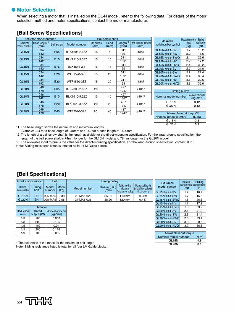
● Motor SelectionWhen selecting a motor that is installed on the GL-N model, refer to the following data. For details of the motorselection method and motor specifications, contact the motor manufacturer.
[Ball Screw Specifications]
GL15N-���-SVGL15N-���-SWGL15N-���-SWQGL15N-���-HVGL15N-���-HVQGL20N-���-SVGL20N-���-SWGL20N-���-SWQGL20N-���-HVGL20N-���-HVQ
Nominalmodel number
GL15N
GL15N
GL15N
GL15N
GL15N
GL20N
GL20N
GL20N
GL20N
Outer diameter(mm)
16
15
16
15
15
20
15
20
20
Lead(mm)
5
10
16
20
30
5
10
20
40
Length*2
(mm)311
1391311
1391311
1391311
1391311
1391427
1747427
1387427
1747427
1747
Model number
BTK1605-2.6ZZ
BLK1510-5.6ZZ
BLK1616-3.6
WTF1520-3ZZ
WTF1530-2ZZ
BTK2005-2.6ZZ
BLK1510-5.6ZZ
BLK2020-3.6ZZ
WTF2040-3ZZ
Base length*1
(mm)034142034142034142034142034142046178046142046178046178
Ball screw
B05
B10
B16
B20
B30
B05
B10
B20
B40
Actuator model number Ball screw shaftLM Guide
model number symbol
Movable sectionmass(kg)1.72.22.42.22.42.73.23.43.63.8
Slidingresistance
(N)16.216.626.617.233.221.021.433.420.636.6
Nominal model number
GL15NGL20N
Timing pulleyMoment of inertia
(kg-cm2)0.120.12
Nominal model numberGL15NGL20N
Allowable input torque*3
(N-m)2.85.3
*1 The base length shows the minimum and maximum lengths.Example: 034 for a base length of 340mm and 142 for a base length of 1420mm
*2 The length of a ball screw shaft is the length available for the direct-mounting specification. For the wrap-around specification, the length of the ball screw shaft is 74mm longer for the GL15N model and 78mm longer for the GL20N model.
*3 The allowable input torque is the value for the direct-mounting specification. For the wrap-around specification, contact THK.Note: Sliding resistance listed is total for all four LM Guide blocks.
[Belt Specifications]
GL15N-���-SVGL15N-���-SWGL15N-���-SWQGL15N-���-HVGL15N-���-HVQGL20N-���-SVGL20N-���-SWGL20N-���-SWQGL20N-���-HVGL20N-���-HVQ
Nominalmodel number
GL15NGL20N
Mass*(kg)
0.380.58
Diameter (PCD)(mm)
35.0138.20
Table movingdistance
/one turn of pulley
110 mm120 mm
Moment of inertia(total of two pulleys)
(kg-cm2)0.2890.447
Model number
22-MA5-02524-MA5-025
Timingbelt
EHEH
Modelnumber
025-MA5025-MA5
Actuator model number Belt Timing pulley
Reductionratio1/31/31/51/51/9
Ratedoutput (W)
100200100200100
Moment of inertia(kg-cm2)
0.0580.1350.040.1180.035
Reducer
LM Guidemodel symbol
Movablesection mass
(kg)
1.21.71.81.71.82.12.62.83.03.2
Slidingresistance
(N)
16.216.626.617.233.221.021.433.420.636.6
Nominal model numberGL15NGL20N
Allowable input torque(N-m)
4.88.1* The belt mass is the mass for the maximum belt length.
Note: Sliding resistance listed is total for all four LM Guide blocks.

MEMO
30
HEAD OFFICE 3-11-6, NISHI-GOTANDA, SHINAGAWA-KU, TOKYO 141-8503 JAPAN INTERNATIONAL SALES DEPARTMENT PHONE:+81-3-5434-0351 FAX:+81-3-5434-0353
CHINATHK (CHINA) CO.,LTD.
TAIWANTHK TAIWAN CO.,LTD.
TAIPEI HEAD OFFICEPhone:+886-2-2888-3818TAICHUNG OFFICEPhone:+886-4-2359-1505 TAINAN OFFICEPhone:+886-6-289-7668
KOREASEOUL REPRESENTATIVE OFFICE
Phone:+82-2-3468-4351SINGAPORETHK LM SYSTEM Pte. Ltd.
NORTH AMERICATHK America,Inc.
HEADQUARTERSPhone:+1-847-310-1111 Fax:+1-847-310-1271CHICAGO OFFICEPhone:+1-847-310-1111 Fax:+1-847-310-1182NEW YORK OFFICEPhone:+1-845-369-4035 Fax:+1-845-369-4909ATLANTA OFFICEPhone:+1-770-840-7990 Fax:+1-770-840-7897LOS ANGELES OFFICEPhone:+1-949-955-3145 Fax:+1-949-955-3149SAN FRANCISCO OFFICEPhone:+1-925-455-8948 Fax:+1-925-455-8965BOSTON OFFICEPhone:+1-781-575-1151 Fax:+1-781-575-9295DETROIT OFFICEPhone:+1-248-858-9330 Fax:+1-248-858-9455TORONTO OFFICEPhone:+1-905-820-7800 Fax:+1-905-820-7811
SOUTH AMERICATHK Brasil LTDA
Phone:+55-11-3767-0100 Fax:+55-11-3767-0101EUROPETHK GmbH
TURKEY OFFICEPhone:+90-216-362-4050 Fax:+90-216-569-7150
DÜSSELDORF OFFICEPhone:+49-2102-7425-0 Fax:+49-2102-7425-299FRANKFURT OFFICEPhone:+49-2102-7425-650 Fax:+49-2102-7425-699STUTTGART OFFICEPhone:+49-7150-9199-0 Fax:+49-7150-9199-888MÜNCHEN OFFICEPhone:+49-8937-0616-0 Fax:+49-8937-0616-26U.K. OFFICEPhone:+44-1908-30-3050 Fax:+44-1908-30-3070ITALY MILANO OFFICEPhone:+39-039-284-2079 Fax:+39-039-284-2527ITALY BOLOGNA OFFICEPhone:+39-051-641-2211 Fax:+39-051-641-2230SWEDEN OFFICEPhone:+46-8-445-7630 Fax:+46-8-445-7639 AUSTRIA OFFICEPhone:+43-7229-51400 Fax:+43-7229-51400-79SPAIN OFFICEPhone:+34-93-652-5740 Fax:+34-93-652-5746
THK France S.A.S.Phone:+33-4-3749-1400 Fax:+33-4-3749-1401
EUROPEAN HEADQUARTERSPhone:+49-2102-7425-0 Fax:+49-2102-7425-217
SHANGHAI OFFICEPhone:+86-21-6219-3000 Fax:+86-21-6219-9890BEIJING OFFICEPhone:+86-10-8441-7277 Fax:+86-10-6590-3557CHENGDU OFFICEPhone:+86-28-8526-8025 Fax:+86-28-8525-6357GUANGZHOU OFFICEPhone:+86-20-8333-9770 Fax:+86-20-8333-9726
HEADQUARTERSPhone:+86-411-8733-7111 Fax:+86-411-8733-7000
THK (SHANGHAI) CO.,LTD.Phone:+86-21-6275-5280 Fax:+86-21-6219-9890
Fax:+886-2-2888-3819
Fax:+886-4-2359-1506
Fax:+886-6-289-7669
Fax:+82-2-3468-4353
Fax:+65-6884-5550INDIABANGALORE REPRESENTATIVE OFFICE
Phone:+91-80-2330-1524
Phone:+65-6884-5500
Fax:+91-80-2314-8226
Global site : http://www.thk.com/
©THK CO., LTD. 20080403 E4 Printed in Japan
LM Actuator GL-N
All rights reserved.
Precautions on UseHandling
(1) Do not disassemble this product. Doing so may allow foreign matter or objects to enter the product or cause deterioration of its precision.
(2) Do not drop or strike this product. Doing so may damage the product. If this product is under a shocked, its functions may be damaged even thoughit looks normal in appearance.
Lubricant(1) Wipe out anti-rust oil completely, then apply lubricator.
(2) Do not mix lubricants with different properties when applying lubricants.
(3) Contact us in advance before using this product in places subject to constant vibration, or in special environments such as clean room, vacuum,low temperatures or high temperatures, regular lubricants may not be used in such environments. Contact us to purchase the dedicated low-dust-raising grease, when using this product in a clean room.
(4) Contact us in advance when using the special lubricant.
(5) Lubrication is essential to ensure the best performance of this product. When no lubricant is applied, it sometimes causes not only the roller to bewear, but also the product life is shortened.
(6) Usually, grease must be applied to this product every 100 kilometers under normal operating conditions. The interval for grease application mustbe determined upon initial inspection.
Notes on Use(1) If a foreign object or foreign matter enters this product, the ball circulation components may be damaged or its functions may deteriorate. Prevent
foreign matters or objects such as trash and chips.
(2) Contact us in advance when using this product is used in environments where coolants enter the interior of the product, because some types ofcoolant may lower the performance of the product’s functions.
(3) This product must be used within a temperature range from +5°C to 40°C. In addition, humidity must be 80% or less and no dew condensation mustoccur. Contact us in advance if planning to use this product in a different range of temperature or humidity.
(4) Contact us in advance when using this product in a place subject to constant vibration or in special environments such as clean room, vacuum, lowtemperatures or high temperatures.
StorageThis product must be leveled in our package or a shipment package during stock. Avoid any place with low temperature, high temperature or highhumidity. If necessary, CAD data (DXF format) for this product may be downloaded from the website of our technical support center.
● “LM GUIDE” and “ ” are the registered trademarks of THK CO., LTD.● There may be differences between products appearing in photographs and the actual product.● The appearance, specifications, and other information are subject to change without prior notice to improve
reliability, function, etc. When deciding to adopt the product, contact us beforehand.● We have exercised great care in preparing this catalog, but it is still possible that are misspellings, omissions of
letters, etc. THK assumes no responsibility or liability for damage resulting from such errors possibly containedherein.
● We employ the basic policy of observing the Foreign Exchange and Foreign Trade Control Law of Japan withregard to the export of our products/technologies or sales for export. For export of our products as discretecomponents, consult THK beforehand.