lm2500, tm2500, lm5000 lm6000, and lms100 gas turbine … · 2017-03-28 · lm - land and marine....
TRANSCRIPT

LM2500, TM2500, LM5000 LM6000, and LMS100Gas Turbine Engines
Robert Boozer
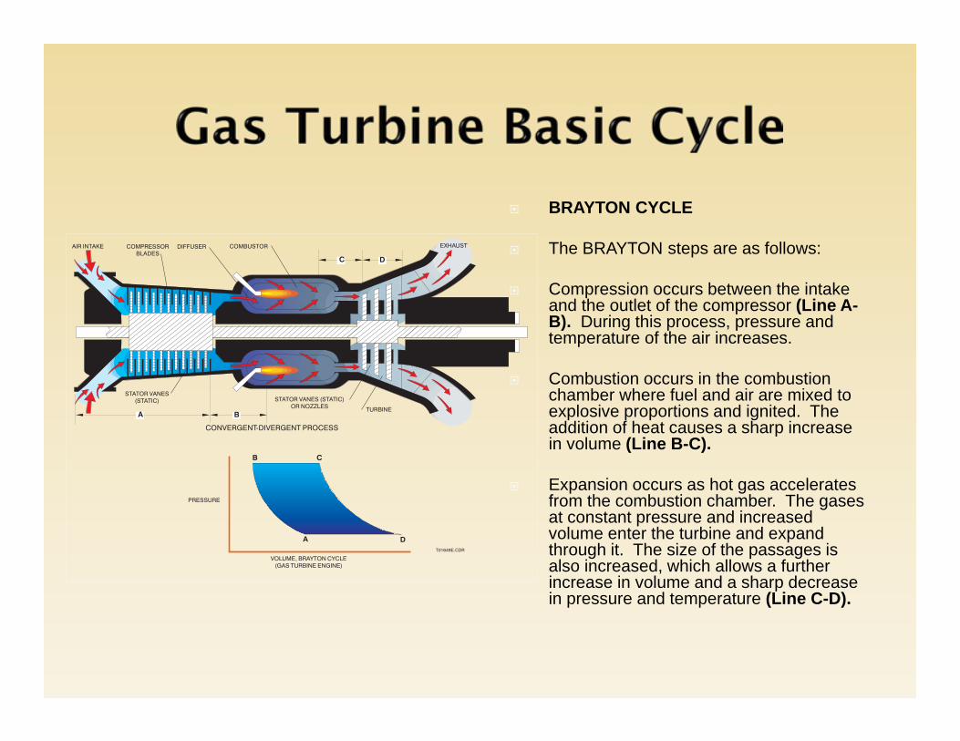
BRAYTON CYCLE
The BRAYTON steps are as follows:
Compression occurs between the intake and the outlet of the compressor (Line A-B). During this process, pressure and temperature of the air increases.
Combustion occurs in the combustion chamber where fuel and air are mixed to explosive proportions and ignited. The addition of heat causes a sharp increase in volume (Line B-C).
Expansion occurs as hot gas accelerates from the combustion chamber. The gases at constant pressure and increased volume enter the turbine and expand through it. The size of the passages is also increased, which allows a further increase in volume and a sharp decrease in pressure and temperature (Line C-D).
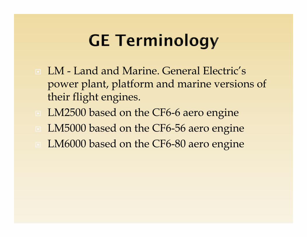
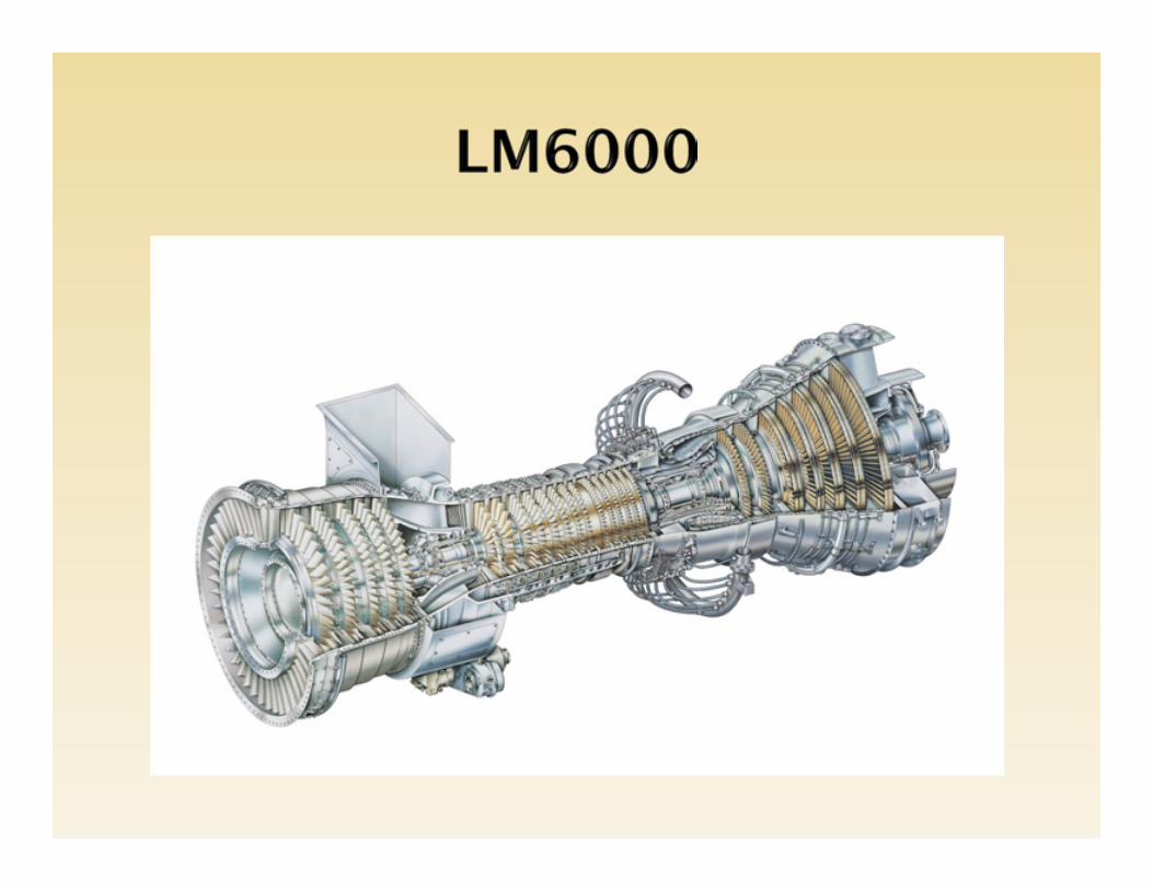
LM - Land and Marine. General Electric’s power plant, platform and marine versions of their flight engines.
LM2500 based on the CF6-6 aero engine LM5000 based on the CF6-56 aero engine LM6000 based on the CF6-80 aero engine

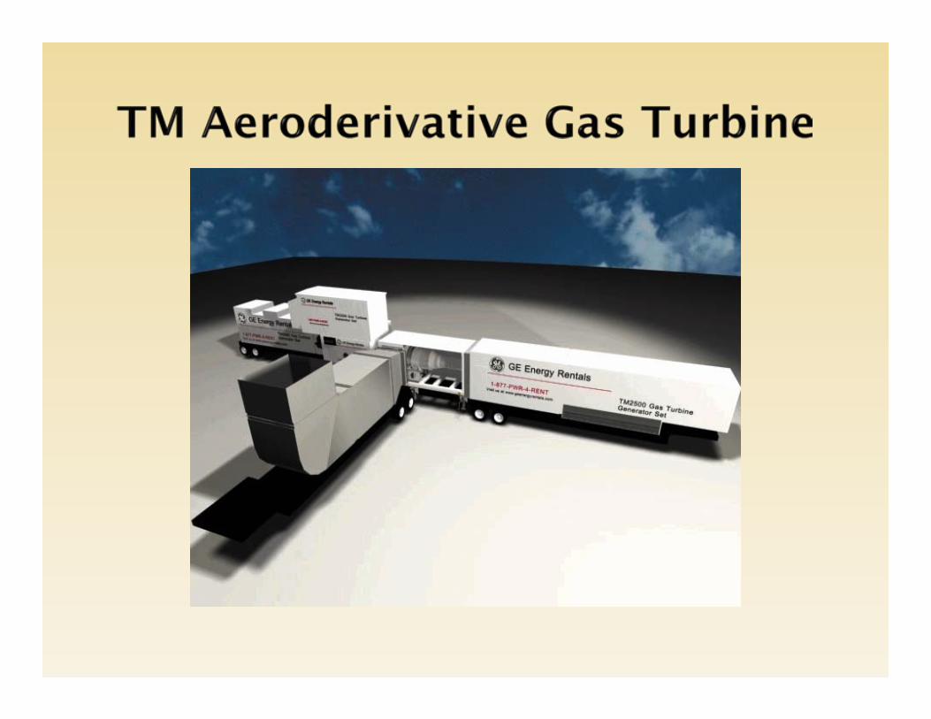
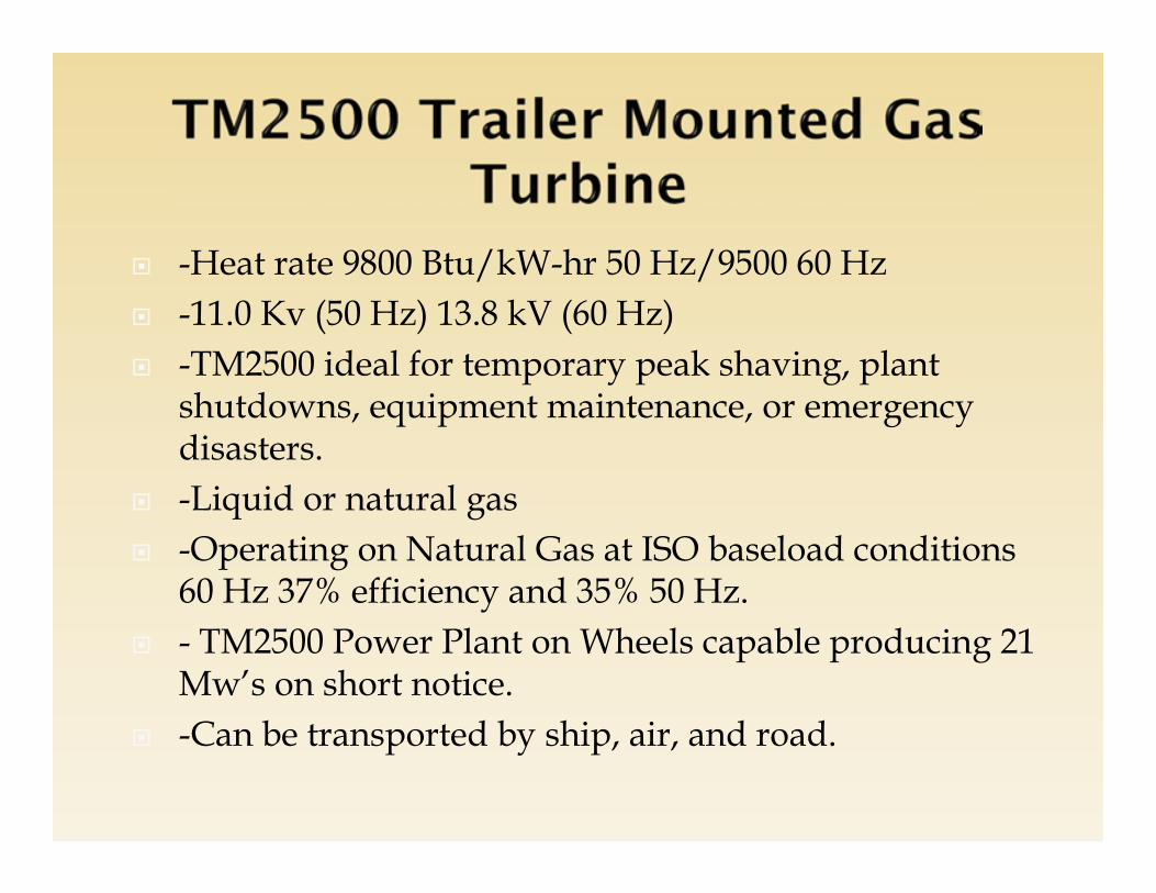
-Heat rate 9800 Btu/kW-hr 50 Hz/9500 60 Hz -11.0 Kv (50 Hz) 13.8 kV (60 Hz) -TM2500 ideal for temporary peak shaving, plant
shutdowns, equipment maintenance, or emergency disasters.
-Liquid or natural gas -Operating on Natural Gas at ISO baseload conditions
60 Hz 37% efficiency and 35% 50 Hz. - TM2500 Power Plant on Wheels capable producing 21
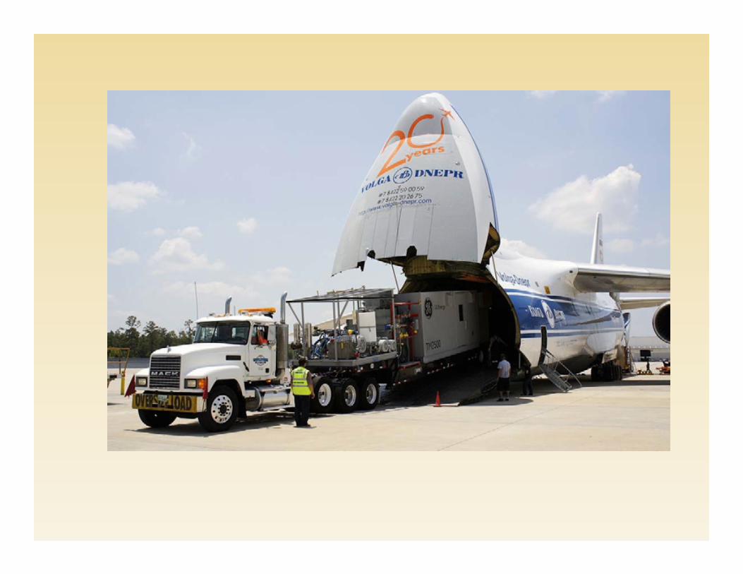
Mw’s on short notice. -Can be transported by ship, air, and road.


LMS100LMS100 comprises a low pressure compressor, an intercooler, a supercore and a power turbine.
Supercore (comprising HP compressor, compressor rear frame , high pressure turbine and intermediate pressure turbine) is a development of the LM6000. The low pressure compressor is from the 6FA industrial
gas turbine.

LMS100 SiteLMS100 comprises a low pressure compressor, an intercooler, a
supercore and a power turbine.

LMS100Quick Specs:Power Class: 98 to 103 MwThermal efficiency: 43.9% to 45%Heat Rate: 7,592 – 7,773 BTU/kW-hr
Three Spool aero derivative industrial gas turbine hot-end drive.Intake-Radial inletLP Compressor- Axial compressor 6 stages. Air deliver to an intercoolerHP Compressor- 14 stage. Over pressure ratio 42:1Combustor – SAC/DLE HP Turbine- Two stageIP Turbine- two axial stages that drive the LP /Power Turbine.LP/Power Turbine- five stage free power turbine. 3600 RPM 60-Hz and 3000 RPM 50-Hz

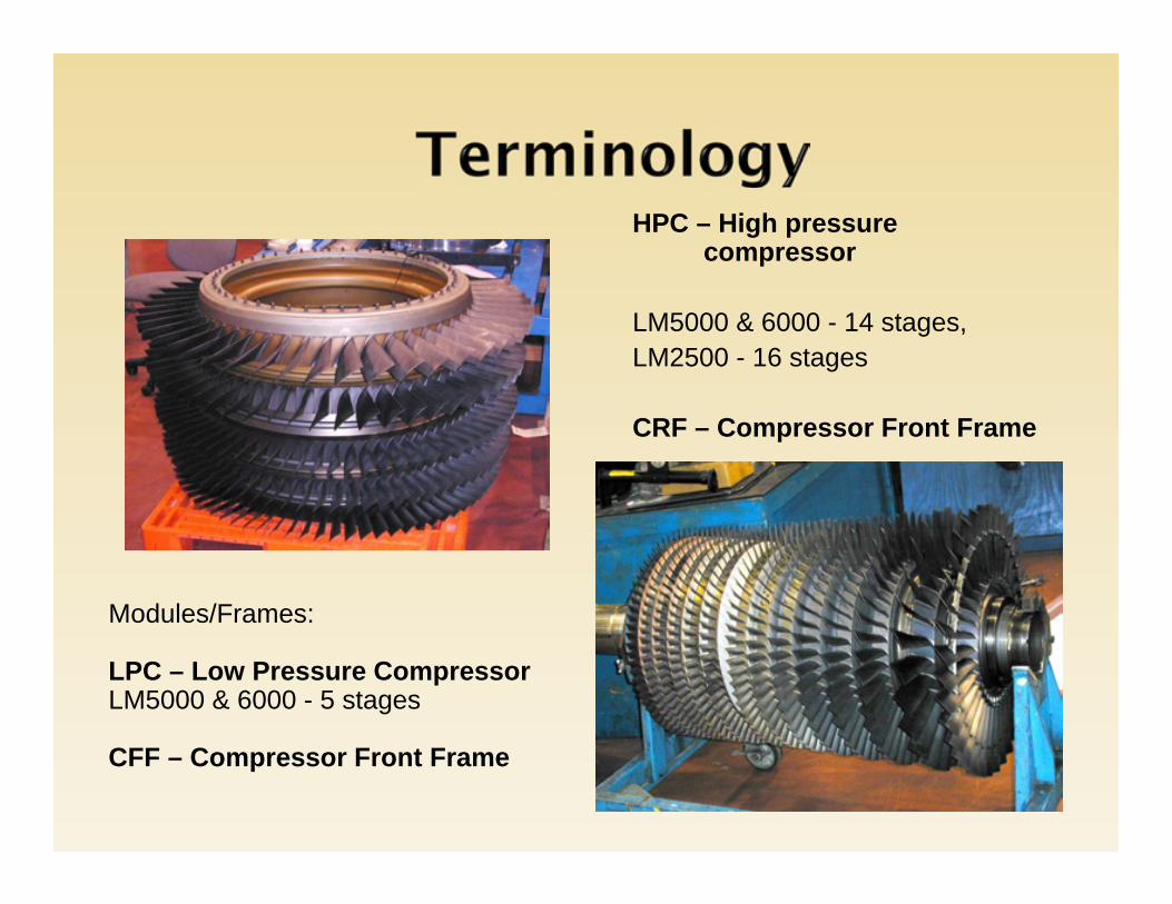
HPC – High pressure compressor
LM5000 & 6000 - 14 stages, LM2500 - 16 stages
CRF – Compressor Front Frame
Modules/Frames:
LPC – Low Pressure CompressorLM5000 & 6000 - 5 stages
CFF – Compressor Front Frame
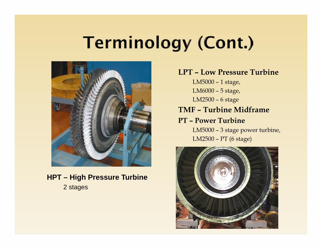
LPT – Low Pressure TurbineLM5000 – 1 stage, LM6000 – 5 stage, LM2500 – 6 stage
TMF – Turbine MidframePT – Power Turbine
LM5000 – 3 stage power turbine,LM2500 – PT (6 stage)
HPT – High Pressure Turbine2 stages

IGV – Inlet Guide VanesVG – Variable GeometryVSV – Variable Stator VanesVBV – Variable Bleed Valves
(Doors)Collector – LM5000 and LM6000
Non-Module Accessories/PartsAGB – Accessory GearboxIGB – Inlet Gearbox
TGB
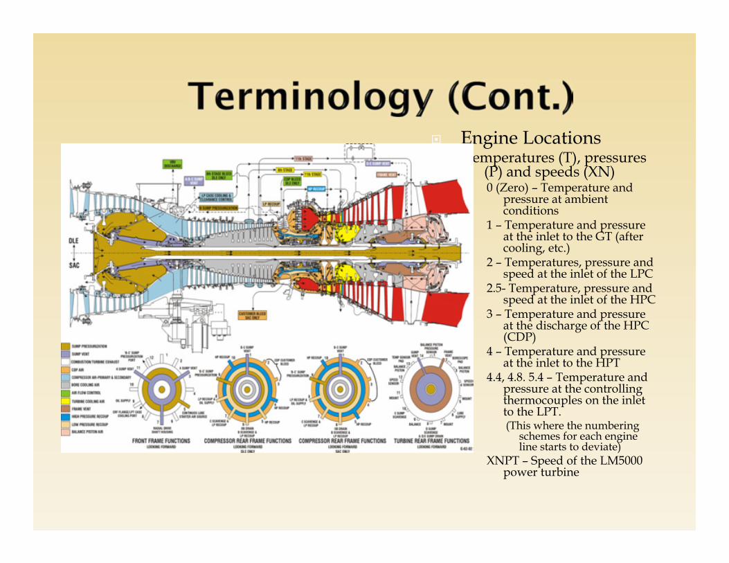
Engine LocationsTemperatures (T), pressures
(P) and speeds (XN)0 (Zero) – Temperature and
pressure at ambient conditions
1 – Temperature and pressure at the inlet to the GT (after cooling, etc.)
2 – Temperatures, pressure and speed at the inlet of the LPC
2.5- Temperature, pressure and speed at the inlet of the HPC
3 – Temperature and pressure at the discharge of the HPC (CDP)
4 – Temperature and pressure at the inlet to the HPT
4.4, 4.8. 5.4 – Temperature and pressure at the controlling thermocouples on the inlet to the LPT.(This where the numbering
schemes for each engine line starts to deviate)
XNPT – Speed of the LM5000 power turbine

Operating/Augmentation terms STIG (Steam injection) – NOx control & power augmentation STIG 80 8000 lb/Hr Steam 60 Hz 48.1 Mw 50 Hz 46.3 Mw STIG 120 120000 lb/Hr Steam 60 Hz 51.6 Mw 50 Hz 49.6 PE PH
Water Injected – NOx Control
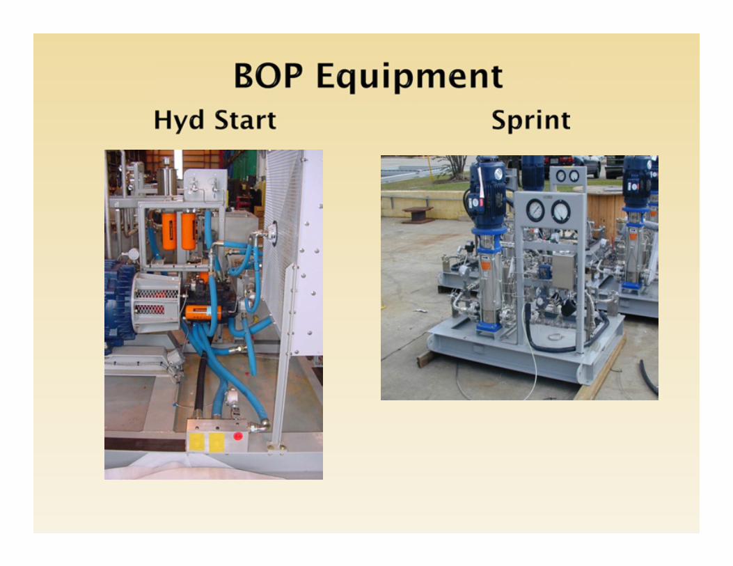
Sprint – Power augmentation Enhanced Sprint
DLE – Dry, low emissions
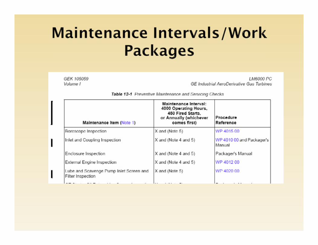
Maintenance Levels Level 1 Any maintenance associated with the
exterior of the engine, up to and including engine removal
Level 2 Any maintenance activity associated with the interior or flowpath. This includes engine module assemblies, and other components
Level 1 and 2 maintenance activities are detailed in Work Packages (WP)

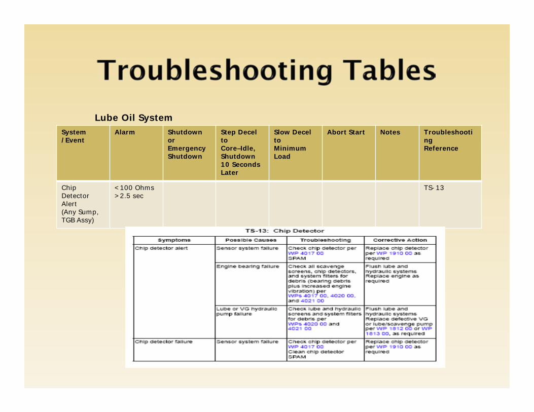
System/Event
Alarm Shutdown orEmergencyShutdown
Step Decel toCore–Idle,Shutdown10 Seconds Later
Slow Decel toMinimum Load
Abort Start Notes TroubleshootingReference
Chip Detector Alert(Any Sump, TGB Assy)
<100 Ohms>2.5 sec
TS-13
Lube Oil System

CHILLER COOLING TOWER

AMMONIA INJECTION
AIR DILUTION BLOWER

SCR 50 HZ GEN/GEARBOX OIL
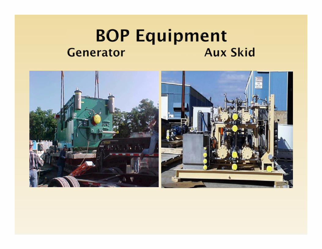
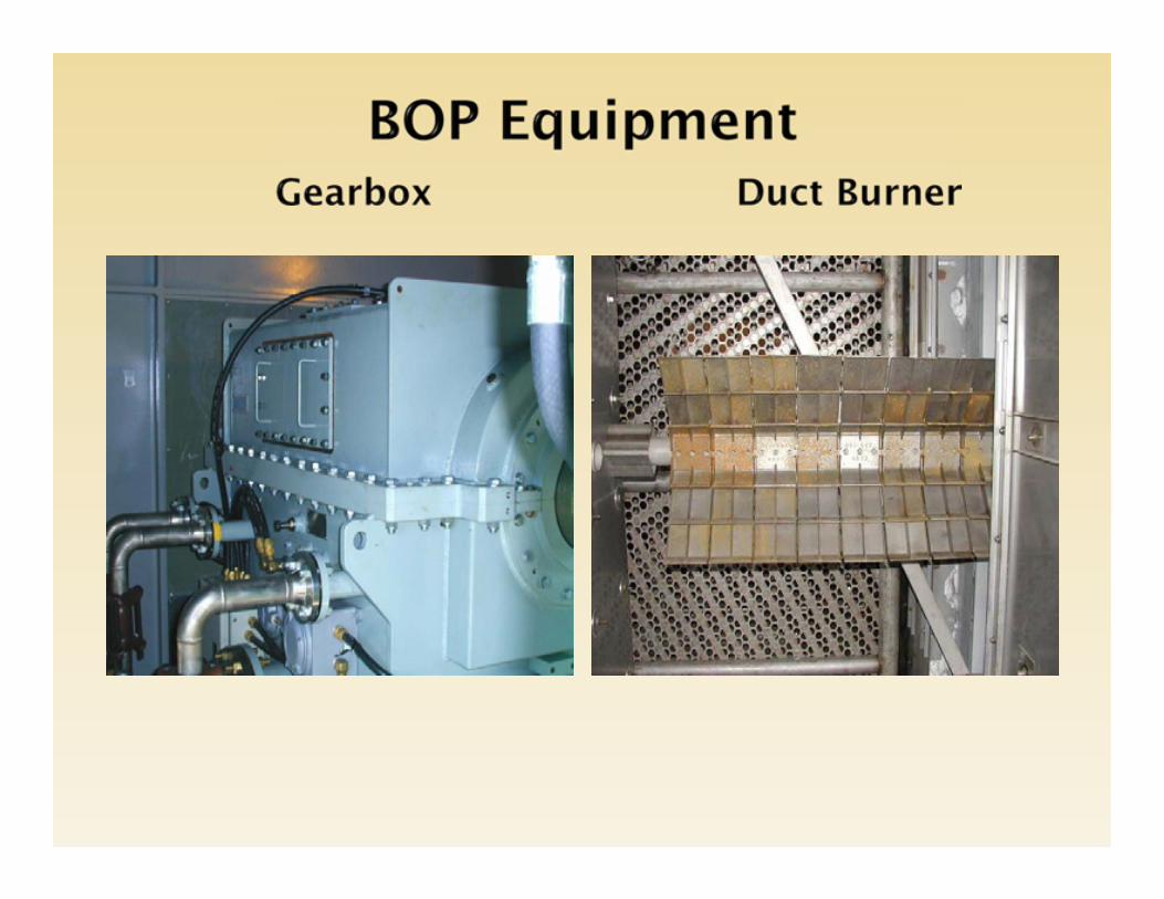
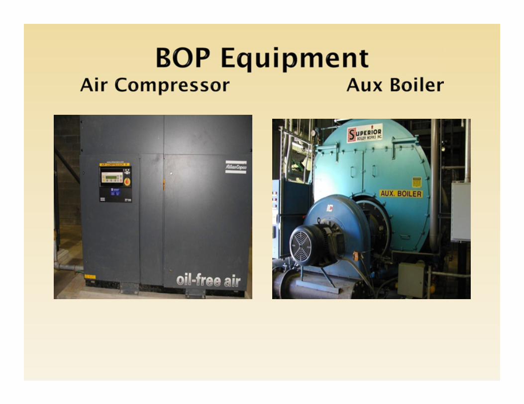
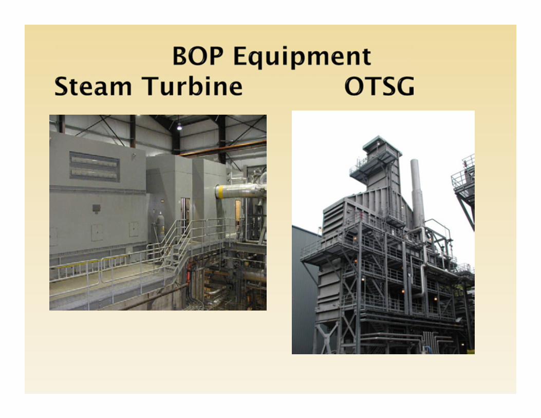
- -Do you have access to LM Tech Doc’s? Contact CSM - -Oil/Gas Analysis Program- -Vibration Analysis (BOP)- -Site Specific Start and Stop Procedures- -Material History- -CMMS/Inventory/Special Tooling/Budgeting/Spare Parts- -Training Plan
Enjoy Your Conference