lncs 5503 - problem-oriented documentation of design patterns · cross-domain documentation,...
TRANSCRIPT
Problem-Oriented Documentation ofDesign Patterns
Alexander Fulleborn1, Klaus Meffert2, and Maritta Heisel1
1 University Duisburg-Essen, [email protected], [email protected]
2 Technical University Ilmenau, [email protected]
Abstract. In order to retrieve, select and apply design patterns in atool-supported way, we suggest to construct and document a problem-context pattern that reflects the essence of the problems that the designpattern is meant to solve. In our approach, software engineers can chooseexamples of source code or UML models from the special domains thatthey are experts in. We present a method that enables software engineersto describe the transformation from a problem-bearing source model toan appropriate solution model. Afterwards, the inverse of that trans-formation is applied to the UML solution model of the existing designpattern, resulting in an abstract problem-context pattern. This patterncan then be stored together with the solution pattern in a pattern li-brary. The method is illustrated by deriving a problem-context patternfor the Observer design pattern.
Keywords: Design patterns, problem derivation, model abstraction,cross-domain documentation, problem-context patterns, UML models,source code.
1 Introduction
Design patterns support software engineers in creating maintainable and extend-able software. In order to select and apply design patterns, practitioners typicallylearn a pattern by reading a design pattern book or paper or by studying UMLdiagrams or source codes, respectively. From our point of view, this kind of doc-umenting design patterns is lacking a machine-processable representation of theproblems in their contexts to be solved by the design patterns. The pattern it-self as the solution for the related problems, however, is represented by UMLmodels, besides explanations in natural language and program code examples.This is why it can be instantiated as a solution model to the concrete problems.As there exists no corresponding problem model, it is difficult for software engi-neers to judge whether their concrete source code or design models, respectively,match the problems that the design pattern is meant to solve. They are forcedto make a comparison that is based on two different formats in order to select anappropriate pattern. In addition, the contexts of the problems are expressed on
M. Chechik and M. Wirsing (Eds.): FASE 2009, LNCS 5503, pp. 294–308, 2009.c© Springer-Verlag Berlin Heidelberg 2009

Problem-Oriented Documentation of Design Patterns 295
different abstraction levels. Due to the lack of cross-domain knowledge, there is arisk that software engineers assume their problem to be of a domain-specific typethat does not match the essence of the problem addressed by a design pattern.Therefore they do not choose the solution provided by such a design pattern,even if it solved their problem.
We are interested in developing methods that help software engineers to re-trieve, select and apply design patterns in a tool-supported way. It should bepossible to apply these methods in the forward as well as in the re-engineeringphase of the software product lifecycle. In this paper, we put special emphasison problem orientation in documenting design patterns. We illustrate our ideasby a re-engineering example. Key of our approach is to enable software engi-neers in their role of pattern documentalists to use their daily, domain-specificwork together with their knowledge about design patterns, in order to completethe documentation of these design patterns. We introduce the possibility forsoftware engineers to start this completion process either with UML models orwith source code, in order to obtain appropriate UML models that reflect theessence of the related problems in their contexts. The resulting artefacts thatwe call problem-context patterns are the basis for our overall methodology ofsemi-automated retrieval, selection and application of design patterns.
Our approach consists of a sophisticated way of documenting the situationbefore and after a design pattern is being applied. For the first part, this docu-menting is done by adding non-functional requirements as annotations to con-crete, domain-specific source code or UML models that have design deficiencies,in order to document the problems in their contexts that the chosen designpattern solves. For the second part, we formally document the solved problemsin a way that they can be compared to the situation before the chosen designpattern was applied. By way of that comparison, the transformation betweenthe situation before and after applying the design pattern is made explicit. Thistransformation is then reused on the design pattern abstraction level in orderto derive the reusable cross-domain representation of the situation before thechosen design pattern is being applied. To obtain the problem-context pattern,the inverse of the transformation is applied to the already existing UML modelof the chosen design pattern that we call solution pattern.
The rest of the paper is organized as follows: in Section 2, we introduce ourmethod for deriving problem-context patterns. We illustrate our method in Sec-tion 3 by using an example from the business domain of human resources andthe Observer design pattern. Section 4 discusses other work in this area. Section5 consists of conclusions of our findings and an outlook on future work.
2 A Method for Deriving Problem-Context Patterns
An overview of our method is given in Table 1.Steps 1 to 4 are performed on the domain-specific level. In Step 1, software en-
gineers choose a concrete, problem-bearing source code or UML model examplethat exists in their specific expert domain. In case software engineers choose a

296 A. Fulleborn, K. Meffert, and M. Heisel
Table 1. Method for deriving problem-context patterns
Step Description1 Choose a problem-bearing, domain-specific source code or UML model example2 Annotate the chosen problem-bearing source code and UML models with problem
motives3 Perform transformations by applying design pattern under consideration to the
chosen source code and UML models4 Annotate the resulting source code and UML models with solution motives5 Annotate the UML solution model of the cross-domain design pattern with the
same solution motives as in Step 46 Perform inverse design pattern transformations to the existing design pattern
UML solution models that are annotated according to Step 5
problem-bearing source code for which no corresponding UML model exists yet(the typical re-engineering case), the latter must be created, as it is needed in thelater steps of the method. In case software engineers choose a problem-bearingUML model as a starting point for the example (the typical forward engineeringcase), they do not need to have corresponding source code, as Steps 5 and 6 areonly based on the UML models. The chosen example must fit to the abstract,natural-language problem description of the design pattern for which they wantto complete the documentation. We assume that software engineers are familiarwith the design pattern, for which they intend to complete the documentation.By using specific examples from expert domains, the procedure of completing adesign pattern documentation is facilitated. The advantage of this approach isthat it is integrated into the usual work of software engineers. The effort neededto complete the documentation of design patterns is minimized, because soft-ware engineers can derive them by doing their daily work of modeling, codingand improving designs.
In Step 2, annotations to the problem-bearing source code and to the UMLmodels are added manually. We call these annotations problem motives. Amethod for deriving problem motives on the source code level can be foundin [5]. On the modeling level, we assign these problem motives to UML modelelements. They represent the non-functional requirements that need to be ful-filled by the source code and UML models after the design pattern wasapplied.
In Step 3, the problem-bearing source code and UML models are transformedstep by step to re-engineered new source code and UML models, according to theknowledge embodied in the design pattern. In case new elements are added orexisting elements are changed, annotations are manually added to these elementsin Step 4. We call these annotations solution motives. They directly correspondto the problem motives in the problem-bearing source code and UML models. Itis also possible that there does not exist a problem motive that corresponds to asolution motive. In this case, the solution provides an additional advantage. It isalso possible that a problem motive without any corresponding solution motiveexists. This indicates a non-optimal solution of the problem.
Problem-Oriented Documentation of Design Patterns 297
The preceding steps all take place on the domain-specific level with its specialvocabulary and semantics, and with limited reuse potential. In the final two stepsof our method, software engineers operate on the generic, cross-domain designpattern level. Here, the main purpose is to complete the documentation of thegeneric design pattern that can be reused across domains. The goal is to find anappropriate cross-domain UML model for the situation before transformationsare being performed.
In Step 5, software engineers annotate the UML solution model of the chosendesign pattern that has been applied on the domain-specific level before. For thispurpose, they reuse the knowledge they already gained in the domain-specificscenario: they take the same solution motives they also used for the domain-specific UML solution model and add them as annotations to the cross-domainUML solution models. Then, they also reuse the transformations, but in thiscase, they apply these transformations inversely to the generic, cross-domainUML solution models of this design pattern. Thus, they derive the cross-domainproblems in their cross-domain contexts that fit to the design pattern. Finally,the obtained problem-context pattern can be stored together with the solutionpattern in a design pattern library. It then can be retrieved and selected accord-ing to the method described in [2].
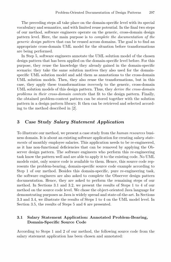
3 Case Study Salary Statement Application
To illustrate our method, we present a case study from the human resources busi-ness domain. It is about an existing software application for creating salary state-ments of monthly employee salaries. This application needs to be re-engineered,as it has non-functional deficiencies that can be removed by applying the Ob-server design pattern. The software engineers who perform this re-engineeringtask know the pattern well and are able to apply it to the existing code. No UMLmodels exist, only source code is available to them. Hence, this source code rep-resents the problem-bearing, domain-specific source code example according toStep 1 of our method. Besides this domain-specific, pure re-engineering task,the software engineers are also asked to complete the Observer design patterndocumentation. Hence, they are asked to perform the remaining steps of ourmethod. In Sections 3.1 and 3.2, we present the results of Steps 1 to 4 of ourmethod on the source code level. We chose the object-oriented Java language fordemonstrating purposes as Java is widely spread and state-of-the-art. In Sections3.3 and 3.4, we illustrate the results of Steps 1 to 4 on the UML model level. InSection 3.5, the results of Steps 5 and 6 are presented.
3.1 Salary Statement Application: Annotated Problem-Bearing,Domain-Specific Source Code
According to Steps 1 and 2 of our method, the following source code from thesalary statement application has been chosen and annotated:

298 A. Fulleborn, K. Meffert, and M. Heisel
010 public class SalaryStatementAppl i cat ion {020 public static void main ( S t r i ng [ ] args ) {030 EmployeeDetail employeeDet = new EmployeeDetail ( ) ;040 acd EmployeeSelector employeeSel = new EmployeeSelector (
employeeDet ) ;050 // User Input in a GUI f i e l d . Sent by an event handler060 employeeSel . updateEmployeeID( ”D026143” ) ;070 }080 }
100 public class EmployeeSelector {110 a private EmployeeDetail employeeDet ;120 private PersNo se l ec tedEmployee ;
130 acd public EmployeeSelector ( EmployeeDetai l employeeDet ) \{140 ac this . employeeDet = employeeDet ;150 \}
180 // Method w i l l be ca l l e d a f t e r user entered employee ID190 public void updateEmployeeID(PersNo ID) {200 se l ec tedEmployee = ID ;210 a employeeDet . changeEmployeeID( ID) ;220 }230 }
300 public class EmployeeDetail {340 public void changeEmployeeID(PersNo ID) {350 // Read employee with given ID from database360 PersName name = . . .370 // Read sa la ry data for employee from database380 Salarybracket sa l a ryb racke t = readSalarybracket ( ID) ;390 // Update the d i sp l ay of the g raph ica l user in t e r face400 . . .410 }
420 public Salarybracket readSalarybracket ( PersNo ID) {430 // Read sa la ry data with given ID from database440 Salarybracket r e s u l t = . . .450 return r e s u l t ;470 }480 }
Listing 1. Salary statement application: annotated problem-bearing, domain-specificsource code
The source code given in Listing 1 represents an application with three classes.The first class, SalaryStatementApplication, is responsible for starting the ap-plication. It creates two graphical elements. The first element is represented bythe class EmployeeSelector and implements a selection list with basic masterdata related to employees. When users have chosen an entry from this list, thedetail information that is needed in this context can be read and displayed. Inour example, the detail information is represented by the second element, theclass EmployeeDetail, and is displayed as a screen area with detail data suchas Name and Salarybracket (which is the technical term for a salary group) ofthe employee, that has been selected by the employee selector. As already men-tioned above, the Observer design pattern should be applied to this source code.According to the terminology used in Observer, the class EmployeeSelector cor-responds to the Subject class, and EmployeeDetail is the observer class to thesubject. The basic non-functional deficiency of this source code is the fact that
Problem-Oriented Documentation of Design Patterns 299
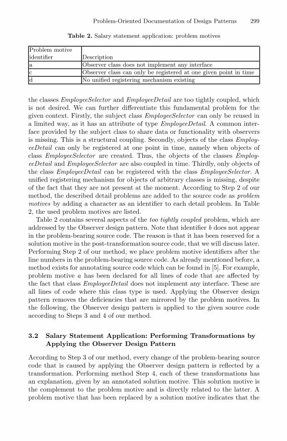
Table 2. Salary statement application: problem motives
Problem motiveidentifier Descriptiona Observer class does not implement any interfacec Observer class can only be registered at one given point in timed No unified registering mechanism existing
the classes EmployeeSelector and EmployeeDetail are too tightly coupled, whichis not desired. We can further differentiate this fundamental problem for thegiven context. Firstly, the subject class EmployeeSelector can only be reused ina limited way, as it has an attribute of type EmployeeDetail. A common inter-face provided by the subject class to share data or functionality with observersis missing. This is a structural coupling. Secondly, objects of the class Employ-eeDetail can only be registered at one point in time, namely when objects ofclass EmployeeSelector are created. Thus, the objects of the classes Employ-eeDetail and EmployeeSelector are also coupled in time. Thirdly, only objects ofthe class EmployeeDetail can be registered with the class EmployeeSelector. Aunified registering mechanism for objects of arbitrary classes is missing, despiteof the fact that they are not present at the moment. According to Step 2 of ourmethod, the described detail problems are added to the source code as problemmotives by adding a character as an identifier to each detail problem. In Table2, the used problem motives are listed.
Table 2 contains several aspects of the too tightly coupled problem, which areaddressed by the Observer design pattern. Note that identifier b does not appearin the problem-bearing source code. The reason is that it has been reserved for asolution motive in the post-transformation source code, that we will discuss later.Performing Step 2 of our method, we place problem motive identifiers after theline numbers in the problem-bearing source code. As already mentioned before, amethod exists for annotating source code which can be found in [5]. For example,problem motive a has been declared for all lines of code that are affected bythe fact that class EmployeeDetail does not implement any interface. These areall lines of code where this class type is used. Applying the Observer designpattern removes the deficiencies that are mirrored by the problem motives. Inthe following, the Observer design pattern is applied to the given source codeaccording to Steps 3 and 4 of our method.
3.2 Salary Statement Application: Performing Transformations byApplying the Observer Design Pattern
According to Step 3 of our method, every change of the problem-bearing sourcecode that is caused by applying the Observer design pattern is reflected by atransformation. Performing method Step 4, each of these transformations hasan explanation, given by an annotated solution motive. This solution motive isthe complement to the problem motive and is directly related to the latter. Aproblem motive that has been replaced by a solution motive indicates that the

300 A. Fulleborn, K. Meffert, and M. Heisel
Table 3. Salary statement application: solution motives
Solution motive identifier Descriptiona Treat observer classes equallyb Possibility to register any number of observersc Possibility to register at any timed Unified registering mechanisme Notify all observers
given problem is solved. A solution motive without any corresponding problemmotive reflects a positive property that has been added without any problemrelationship. This is true for solution motive b, that we already mentioned, andit is true for solution motive e. An identifier of a solution motive that equalsan identifier of the problem motive indicates that it solves the correspondingproblem. An overview of the solution motives used in this example is given inTable 3.
The transformations used to apply the Observer pattern are all related tothese solution motives. For each transformation, we give the resulting sourcecode including the solution motives. If the transformation is a deletion, onlythe deleted source code is shown. For better traceability, the line numbers fromListing 1 are given, too. Equal line numbers in the post-transformation sourcecode indicate a change, new line numbers indicate an insertion.
Transformation T1: declaring the subject without relation to any ob-serverIn this transformation, the observer and subject class are decoupled from eachother by deleting the static attribute for observer from the subject class.109 /**@@motive a(1): Treat observer classes equally*/110 a private EmployeeDetail employeeDet;
Transformation T2: constructing the subject without relation to anyobserverThis transformation causes the change of two dependent parts within the sourcecode, namely of a constructor declaration and the creation of objects of classEmployeeSelector by this constructor. The changed constructor looks as follows:127 /**@@motive a(2): Treat observer classes equally*/128 /**@@motive c(1): Possibility to register at any time*/129 /**@@motive d(1): Unified registering mechanism*/130 public EmployeeSelector(){137 /**@@motiv a(3): Treat observer classes equally*/138 /**@@motive c(2): Possibility to register at any time*/139 /**@@motive d(2): Unified registering mechanism*/140 this.employeeDet = employeeDet;

Problem-Oriented Documentation of Design Patterns 301
As a result, the constructor call must also be adjusted:
037 /**@@motive a(4): Treat observer classes equally*/038 /**@@motive c(3): Possibility to register at any time*/039 /**@@motive d(3): Unified registering mechanism*/040 EmployeeSelector employeeSel = new EmployeeSelector();
As every solution motive can appear more than once, we use a serial numberper motive, which we put into brackets behind each solution motive.
Transformation T3: introducing the base class for observerPart of the core concept of the Observer design pattern is the usage of an abstractbase class for observer classes. In this context, we call this class Observer. Firstly,we introduce this base class:
899 /**@@motive a(5): Treat observer classes equally*/900 public abstract class Observer {909 /**@@motive e(1): Notify all observers*/910 public abstract void update(Object state);920 }
Next, the specialized observer class EmployeeDetail can inherit from this class:
299 /**@@motive a(6): Treat observer classes equally*/300 public class EmployeeDetail extends Observer {
Furthermore, the abstract method needs to be implemented:309 /**@@motive e(2): Notify all observers*/310 public void update(Object state){320 changeEmployeeID((PersNo)state);330 }
Transformation T4: introducing a universal registration mechanismwithin the subjectNow, we can introduce a registration method with a variable for storing observerreferences:109 /**@@motive b(1): Possibility to register any number of observers*/110 private List<Observer> observers = new Vector();
147 /**@@motive a(7): Treat observer classes equally*/148 /**@@motive b(2): Possibility to register any number of observers*/149 /**@@motive c(4): Possibility to register at any time*/150 public void register(Observer a_observer){160 observers.add(a_observer);170 }
The newly introduced solution motive with the identifier b has no correspond-ing problem motive in the problem-bearing source code. This means that it isan additional advantage of the solution that was not seen as a problem before.
Transformation T5: unified notification of all observers by the subjectThe way the subject notifies its observers can be adjusted, too. Firstly, we in-troduce a new method for notifications:

302 A. Fulleborn, K. Meffert, and M. Heisel
222 /**@@motive e(3): Notify all observers*/223 public void notify(){224 /**@@motive a(8): Treat observer classes equally*/225 /**@@motive e(4): Notify all observers*/226 for(Observer observer:observers){227 observer.update(selectedEmployee);228 }229 }
Now the method call must be placed at a suitable location:209 /**@@motive e(5): Notify all observers*/210 notify();
The remaining reference to EmployeeDetail in line 030 of the problem-bearingsource code can be replaced by a reference to the class Observer. However, thisis not needed here. To give readers of this paper a complete overview aboutthe resulting post-transformation source code, we provide it as a listing in anappendix at the end of the long version of this paper.1
3.3 Salary Statement Application: Annotated Problem-Bearing,Domain-Specific UML Model
Until now we performed Steps 1 to 4 of our method on the source code level.Next, we repeat these steps on the UML model level, because Steps 5 and 6are based on the UML models. We start with Steps 1 and 2. First, we createdomain-specific UML models of the annotated problem-bearing source code.Extracting the model can be automated to a certain extent. Next, the problemmotives of the source code are added to those model elements that cause theproblem, according to Step 2 of our method. While taking over the problemmotives, some information gets lost, as not all of the problem motives can betaken over to the UML model level. The reason is that problem motives in thesource code can also relate to single program statements that do not appear onthe UML model level. However, this loss of information can be reduced by usingUML comments, which contain these program statements with assigned problemmotives in order to give software engineers some guidance in implementing thedetails. The resulting UML problem-context model, which is needed later in Step6 to derive an appropriate problem-context pattern, is shown in Figure 1.
In this problem-context model, the problem motive identifiers of the annotatedproblem-bearing source code are assigned to the relevant elements using the tildesymbol. For example, annotation motives: a is assigned to the problem-causingattribute employeeDet in the class EmployeeSelector. As stated in Table 2, thisidentifier means Observer class does not implement any interface, which refinesthe basic problem that class EmployeeSelector and class EmployeeDetail aretoo tightly coupled. This problem is expressed by a static attribute that limitsthe reuse of class EmployeeSelector. For the sake of readability, we only look at1 Available at http://swe.uni-duisburg-essen.de/techreports/Fase09Longversion.pdf.

Problem-Oriented Documentation of Design Patterns 303
Fig. 1. Salary statement application: annotated UML model (problem-context model)
the structural aspects in our example. In our research work, we also applied thedescribed steps to sequence diagrams, which works well, but does not provideadditional information and does not necessitate any extension of the method.
3.4 Salary Statement Application: Annotated ResultingDomain-Specific UML Model
In this section, we repeat Step 2 of our method on the modeling level. Theresulting domain-specific UML solution model is directly generated from the re-engineered source code. Then, software engineers analyze the differences betweenthe pre- and post-transformation UML models by considering the differences inthe pre- and post-transformation source codes, and annotate the models withcomments about the solved problem. The resulting annotated class diagram isshown in Figure 2.
Note that there are comments assigned to several model elements. Thesemodel elements are exactly the classes or relationships that have been changedfrom the problem-context model. The comments log the type and the reason forthe change. The type of changes, namely adding or deleting is described by anappropriate keyword. The reason for the change is described by adding solutionmotives, which also establish relationships to the underlying problem motivesin the problem-context model. For example, a comment is added to the classEmployeeSelector that states that the attribute employeeDet is deleted due tosolution motive a. In the problem-context model, this attribute still exists andis annotated with the corresponding problem motive. By using a numberingwithin the used motives, software engineers can better reflect the order of thesingle transformation steps and the involved model elements.

304 A. Fulleborn, K. Meffert, and M. Heisel
Fig. 2. Salary statement application: annotated resulting post-transformation UMLsolution model
3.5 Deriving a Fitting Problem-Context Pattern (Cross-Domain)
Up to this point in the procedure, all activities take place on the domain-specificlevel. From now on, the cross-domain level is considered by following Steps 5 and6 of our method. Here, the main purpose is to complete the generic, cross-domainObserver design pattern by finding an appropriate cross-domain UML model, aproblem-context pattern for the pre-transformation situation. First, the existingUML solution model of the Observer design pattern is annotated according toStep 5 of our method. For this purpose, the solution motives that have been usedto annotate the domain-specific salary statement UML solution model are takenas a starting point. Thus, software engineers extend the Observer UML solutionmodels with information about the problems they solve and with informationabout the way how they solve them. As in the domain-specific example, forthe sake of readability and simplicity, we use a variant of the Observer designpattern. In this variant, no explicit subject superclass exists, and observers donot ask separately for state changes. Instead, the subject provides the observersproactively with information about state changes. While adding informationabout the performed transformations, the transformed model elements are alsoabstracted. The result is illustrated in Figure 3.
Note that annotations have also been changed. They are adapted to the pat-tern in the sense of an abstraction. For example, the model element attribute

Problem-Oriented Documentation of Design Patterns 305
Fig. 3. Annotated UML solution model of the Observer design pattern (variant) ac-cording to method Step 5
employeeDet of class ConcreteSubject that can be found under the deleted anno-tation has been renamed to attribute concreteObserver. This annotated solutionpattern is the starting point for the next step of inverse transformations. InStep 6 of our method, a suitable Observer problem-context pattern is derived byapplying inverse transformations. All transformation steps, that have been per-formed before on the domain-specific level, started from problem-bearing models(problem-context models) and resulted in solution models. On the cross-domainlevel, solution models exist already, as they are described in the literature [3].Thus, in order to obtain appropriate problem models for the Observer designpattern, the knowledge about the way to transform the problem-bearing modelsinto solution models on the domain-specific level is reused, but in the oppositedirection. For example, in Figure 3 the class Observer is annotated with:
added:(1) class Observer, motives: a(3)(2) method update(), motives: e(1)
This annotation is based on the transformations add class Observer and addmethod update() to class Observer. Thus, the appropriate inverse transformationsare:delete method update() from class Observerdelete class Observer

306 A. Fulleborn, K. Meffert, and M. Heisel
Fig. 4. Derived problem-context pattern of the Observer design pattern according tomethod Step 6
Besides performing inverse transformations, also problem motives are neededin the derived problem-context pattern, which establish the link to the solutionmotives in the solution pattern. These problem motives are derived from thedomain-specific problem-context model. The derived problem-context pattern isillustrated as a result of the described actions in Figure 4.
The illustrated problem-context pattern abstractly describes a possible start-ing point for applying the Observer design pattern, using the same means ofexpression as the solution, namely UML. Together with the UML solution mod-els, the solution pattern, it forms the Observer design pattern and can be storedin a pattern library. The problem-context pattern is the access key for a semi-automated pattern retrieval and selection method. Such a method is describedin [2].
4 Related Work
There has only been little work on documenting the problem essence of designpatterns in an appropriate way. Different from our approach of expressing theproblem essence as UML models, other contributors take UML meta models asthe basis for their methods. Mili and El-Boussaidi [6] use transformation metamodels, besides problem and solution meta models, to describe appropriate de-sign pattern problem models and the way they are transformed to design patternsolution models. Differently from our method, their problem meta models do notcontain any non-functional requirement or problem description that would becomparable to our problem motives.
Kim and El Khawand [4] propose to rigorously specify the problem domain ofdesign patterns. In contrast to Mili and El-Boussaidi [6] and our approach, theydo not describe the problem-bearing model before a design pattern is appliedto it. Moreover, they focus on the functional aspects of design patterns, noton non-functional aspects. The authors are mainly interested in developing toolsupport for checking whether existing UML models conform to known designpatterns.
The work of Fanjiang and Kuo [1] introduces the concept of design-pattern-specific transformation rule schemata to be used as an additional design pat-tern documentation. The transformation steps, which are described in naturallanguage, are similar to ours and are helpful in applying design patterns. How-ever, as the authors do not intend to support software engineers in their role

Problem-Oriented Documentation of Design Patterns 307
of documentalists, they do not give guidance on deriving transformation ruleschemata.
The work of O’Cinneide and Nixon [7] aims at applying design patterns toexisting legacy code in a highly automated way. They target code refactorings.Their approach is based on a semi-formal description of the transformationsthemselves, needed in order to make the changes in the code happen. In con-trast to our method, they describe precisely the transformation itself and underwhich pre- and postconditions it can successfully be applied. In our work, weillustrate the situation before and after the transformation. To a certain extent,the described preconditions of the transformations can be compared with ourproblem context as it outlines the situation before the design pattern is applied.The advantage of our approach, however, is that we explicitly describe the non-functional deficiencies by using annotations in the source code of the sub-optimalsituation.
5 Summary and Future Work
In this paper, we have presented a method for the problem-oriented documen-tation of design patterns that consists of 6 steps. The results of Steps 1 to 2 arean annotated problem-bearing source code and the corresponding UML mod-els, stemming from the practical work of software engineers. By applying thechosen design pattern and by adding solution motives to the resulting sourcecode and corresponding UML models, the outcome of Steps 3 and 4 are thetransformed and annotated solution source code and UML models. In Step 5,the same solution motives are used to obtain annotated UML solution models ofthe cross-domain design pattern. Finally, inverses of transformations accordingto Step 3 are applied to these UML solution models, which result in a problem-context pattern that fits to the chosen design pattern.
The use of expert domain, real world examples on the source code or onthe modeling level in order to derive the problem-context pattern on the cross-domain level is novel and makes this approach especially useful and efficient in re-engineering as well as in forward engineering projects. In addition to that reuse ofdomain-specific knowledge on the abstract level, reusing the already documentedUML models of the design pattern solution part to derive the abstract problem-context pattern is efficient.
To demonstrate how our method works, we used Observer, a behaviouraldesign pattern. In our research work, we also applied it to creational and struc-tural patterns, which works well, too. Besides the scenario of completing existingdesign patterns that are known from the literature, it also seems promising tosupport the creation of new patterns in this way. This aspect is part of our futurework. Furthermore, we are working on the development of a problem statementlanguage that helps to reuse generic, standardized problems by making use ofthe ideas provided by Willms et al. [8]. Another subject area we want to addressis the cross-domain reuse of functional requirements as opposed to the typicalnon-functional requirements that are addressed by design patterns.

308 A. Fulleborn, K. Meffert, and M. Heisel
References
1. Fanjiang, Y.-Y., Kuo, J.-Y.: A pattern-based model transformation approach toenhance design quality. In: Cheng, H.D., Chen, S.D., Lin, R.Y. (eds.) JCIS 2006,Proceedings of the 2006 Joint Conference on Information Sciences. Atlantis Press(2006)
2. Fulleborn, A., Heisel, M.: Methods to create and use cross-domain analysis patterns.In: Zdun, U., Hvatum, L. (eds.) EuroPLoP 2006, Proceedings of the 11th EuropeanConference on Pattern Languages of Programs, pp. 427–442. Universitatsverlag Kon-stanz (2007)
3. Gamma, E., Helm, R., Johnson, R.E., Vlissides, J.: Design patterns: Abstractionand reuse of object-oriented design. In: Nierstrasz, O. (ed.) ECOOP 1993. LNCS,vol. 707, pp. 406–431. Springer, Heidelberg (1993)
4. Kim, D.-K., Khawand, C.E.: An approach to precisely specifying the problem do-main of design patterns. Journal of Visual Languages and Computing 18(6), 560–591(2007)
5. Meffert, K., Philippow, I.: Supporting program comprehension for refactoring-operations with annotations. In: Fujita, H., Mejri, M. (eds.) Proceedings of thefifth SoMeT 2006: New Trends in Software Methodologies, Tools and Techniques,vol. 147, pp. 48–67. IOS Press, Amsterdam (2006)
6. Mili, H., El-Boussaidi, G.: Representing and applying design patterns: What is theproblem? In: Briand, L.C., Williams, C. (eds.) MoDELS 2005. LNCS, vol. 3713, pp.186–200. Springer, Heidelberg (2005)
7. O’Cinneide, M., Nixon, P.: A methodology for the automated introduction of designpatterns. In: ICSM 1999: Proceedings of the IEEE International Conference onSoftware Maintenance, p. 463. IEEE Computer Society Press, Washington (1999)
8. Willms, J., Wentzlaff, I., Specker, M.: Kreativitat in der informatik: Anwendungs-beispiele der innovativen prinzipien aus triz. In: Informatik 2000, Neue Horizonteim neuen Jahrhundert, 30. Jahrestagung der Gesellschaft fur Informatik. Springer,Heidelberg (2000)