lng vehicle fuel tank installation and operation … vehicle fuel tank installation and operation...
TRANSCRIPT
LNG Vehicle Fuel Tank Installation and Operation Manual
Manual P/N 7950-8359 Publication # TW-359
Do not attempt to use or maintain these units until you read and understand these instructions. Do not permit untrained persons to use or maintain this equipment. If you do not understand these instructions, contact Taylor-Wharton for dditional information. a
Table of Contents WARNING 3
Safety Precautions for Liquefied Natural Gas 3 References 4
INTRODUCTION 5 General Information 5
INSTALLATION 7 Freight Damage Precautions 7 Handling 7 Tank Supports 7 Level Gauge 8 LNG Fuel System 8 Fittings and Thread Sealants 9 Vent Stack 9 Heat Exchanger 9 Heat Exchanger Relief Valve 10 Over Pressure Regulator 10 Fuel Shut-Off Solenoid Valve 10 Taylor-Wharton Recommended Fuel System Components 11 Leak Test 11
OPERATION 12 First Fill 12 Normal Filling 13 Normal Operation 14
MAINTENANCE 15 Draining the Tank 15 Purging the Tank 16 Hand Valves 17 Relief Valves 17 Check Valves 17 Excess Flow Valve 18 Tank Pressure Control Regulator 18 Fill and Vent Receptacles 19 Manifold Removal and Replacement 20 Liquid Level Gauge and Sender 21 Leak Test 21 Checking Vacuum 22 Trouble-Remedy Guide 24 Replacement Parts 25
APPENDIXES 26 Appendix 1 – LNG Vehicle Tank General Arrangement 26 Appendix 2 – LNG Heat Exchanger General Arrangement 26

3
WARNING The following safety precautions are for your protection. Before installing, operating, or maintaining this equipment read and follow all safety precautions in this section and in reference publications. Failure to observe all safety precautions can result in property damage, personal injury, or possibly death. It is the responsibility of the purchaser of this equipment to adequately warn the user of the precautions and safe practices for the use of this equipment and the cryogenic fluid stored in it. Safety Precautions for Liquefied Natural Gas Natural gas is a colorless, odorless, tasteless, flammable gas. Natural gas is mostly methane with small amounts of carbon dioxide, nitrogen, ethane, and propane. Liquefied natural gas (LNG) is obtained by cooling natural gas until it becomes a liquid. Natural gas becomes a liquid at a temperature of -259°F (-161°C) under normal atmospheric pressure. Upon release from containment LNG will vaporize and expand to about 600 times the volume of the liquid. Natural gas colder than -170°F is heavier than ambient air at 60°F. As natural gas warms it becomes lighter than air.
Flammable – Eliminate Natural Gas Accumulation and Ignition Sources Concentrations of natural gas in air are relatively easy to ignite by a low energy spark. Smoking, open flames, unapproved electrical equipment, and other ignition sources must not be permitted. LNG vehicle tanks should be stored outdoors in well ventilated areas. The tank should be safely drained and purged with inert gas before maintenance or indoor storage. Vehicles with fueled tanks may be stored indoors only in maintenance facilities with proper ventilation equipment, consult NFPA guidelines and your local fire marshal. Extreme Cold - Cover Eyes and Exposed Skin Accidental contact of LNG or cold natural gas with the skin or eyes may cause a freezing injury similar to frostbite. Protect your eyes and cover the skin where the possibility of contact with the liquid, cold equipment, or the cold gas exists. Safety equipment should be worn during filling, draining, maintaining, or any other time liquid ejection, liquid splashing, or cold gas can issue forcefully from equipment. Safety equipment consists of a full polycarbonate face shield, insulated gloves that can be easily removed and long sleeves. Trousers without cuffs should be worn outside boots or over the shoes to shed spilled liquid. Asphyxiate - Keep Equipment Area Well Ventilated Although natural gas is non-toxic, it can cause asphyxiation in a confined area without adequate ventilation. Any atmosphere not containing enough oxygen for breathing can cause dizziness, unconsciousness, or even death. Natural gas, a colorless, odorless, and tasteless gas, cannot be detected by the human senses and will be inhaled normally as if it were air. Pipe line natural gas contains an additive that gives the gas an odor. LNG, and the gas created when LNG boils, does not have an odorant. Without adequate ventilation, natural gas will displace the normal air resulting in a non-life-supporting atmosphere.

4
References Installation, operation, and maintenance of Taylor-Wharton’s LNG Vehicle Fuel Tank shall be in accordance with the documents listed below: For more detailed information concerning safety precautions and safe practices to be observed when handling cryogenic liquids consult CGA pamphlet P-12 Handling Cryogenic Liquids available from the Compressed Gas Association. Compressed Gas Association 1235 Jefferson Davis Highway Arlington, VA 22202 Webpage: www.cga.net For detailed safety information regarding LNG consult pamphlet NFPA 57 Liquefied Natural Gas (LNG) Vehicular Fuel Systems Code available from the National Fire Protection Association. National Fire Protection Association 1 Batterymarch Park PO Box 9101 Quincy, MA 02269-9101 Webpage: www.nfpa.org For detailed information on LNG fuel systems consult SAE J2343 Recommended Practices for LNG Powered Heavy-Duty Trucks available from the Society of Automotive Engineers. Society of Automotive Engineers 400 Commonwealth Drive Warrendale, PA 15096 Webpage: www.sae.org

5
INTRODUCTION This manual provides information for the operation, installation, and maintenance of Taylor-Wharton's LNG Vehicle Fuel Tanks. The LNG Vehicle Fuel Tanks are intended to store pressurized liquefied natural gas on-board a vehicle for use as an engine fuel. Product specifications, flow diagram, views, and important dimensions are shown on the general arrangement drawing provided in the back of this manual. General Information Taylor-Wharton’s LNG Vehicle Fuel Tanks are double-walled vacuum-insulated pressure vessels. Taylor-Wharton LNG Vehicle Tanks are designed and manufactured in compliance with: DOT-4L (Vessels to 119 Gallons Gross) ASME, Section VIII, Division 1 (Vessels exceeding 119 Gallons Gross) National Fire Protection Association (NFPA) 57 Society of Automotive Engineers (SAE) J2343 California Code of Regulations Title 13, Division 2, Chapter 4, Article 2 Texas Administration Code, Title 16, Part 1, Chapter 13, Subchapter M LNG is extremely cold. The inner vessel or liquid container is designed to operate safely at temperatures down to -320 degrees F and pressures up to 230 psig. The inner vessel and outer jacket are constructed from type 304 stainless steel. The components (valves, regulators, check valves, etc.) used on this product are O.E.M. approved for the intended application. The vacuum space between the liquid container and the jacket is designed to act as a thermal barrier. A multi-layer insulation consisting of aluminum foil and fiberglass known as S.I. or super insulation is contained inside the vacuum space. The tanks are designed to not vent gas for a nominal period of three days after being filled to 100% net capacity. When the tank is full to 75% of the net capacity the nominal hold time is five days before venting gas. Once venting begins, the rate of venting will be 1% nominal per day by weight, based on the full weight of fuel. The tank must be filled using “saturated” LNG fuel in order to maintain proper pressure. Saturated LNG is warmed under pressure, typically between 100 and 130 psig, in purpose built LNG vehicle fueling stations. Saturated LNG will begin to boil and expand when its pressure is reduced below its “saturation pressure”. This makes it possible to maintain adequate pressure within the tank to provide fuel to the engine without using a pump. A pressure control system, factory installed on the tank, reduces the tank pressure when it is excessively high. When the engine is running, the system removes gas from the top of the tank, reducing the tank pressure. When the tank is at its proper operating pressure, the circuit removes liquid from the tank in order to maintain pressure. The pressure control system is adjustable to provide adequate fuel pressure per the engine manufacturer’s requirements. Note: This product is intended to store LNG on-board a vehicle for use as engine fuel. It is
not intended to transport LNG for the purpose of commerce.

Vacuum Space and Super Insulation
Stainless Steel Inner Vessel
Stainless Steel Jacket
Figure 1: Cut-Away Image of Fuel Tank
6
7
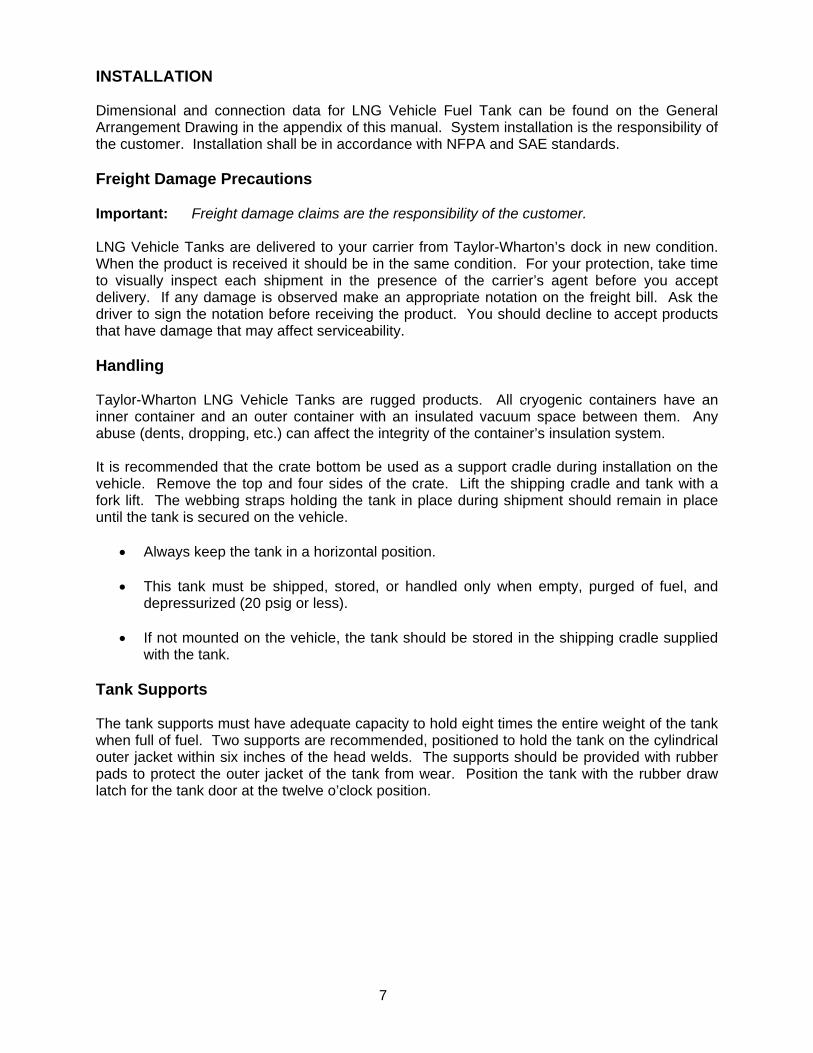
INSTALLATION Dimensional and connection data for LNG Vehicle Fuel Tank can be found on the General Arrangement Drawing in the appendix of this manual. System installation is the responsibility of the customer. Installation shall be in accordance with NFPA and SAE standards. Freight Damage Precautions Important: Freight damage claims are the responsibility of the customer. LNG Vehicle Tanks are delivered to your carrier from Taylor-Wharton’s dock in new condition. When the product is received it should be in the same condition. For your protection, take time to visually inspect each shipment in the presence of the carrier’s agent before you accept delivery. If any damage is observed make an appropriate notation on the freight bill. Ask the driver to sign the notation before receiving the product. You should decline to accept products that have damage that may affect serviceability. Handling Taylor-Wharton LNG Vehicle Tanks are rugged products. All cryogenic containers have an inner container and an outer container with an insulated vacuum space between them. Any abuse (dents, dropping, etc.) can affect the integrity of the container’s insulation system. It is recommended that the crate bottom be used as a support cradle during installation on the vehicle. Remove the top and four sides of the crate. Lift the shipping cradle and tank with a fork lift. The webbing straps holding the tank in place during shipment should remain in place until the tank is secured on the vehicle.
• Always keep the tank in a horizontal position.
• This tank must be shipped, stored, or handled only when empty, purged of fuel, and depressurized (20 psig or less).
• If not mounted on the vehicle, the tank should be stored in the shipping cradle supplied
with the tank. Tank Supports The tank supports must have adequate capacity to hold eight times the entire weight of the tank when full of fuel. Two supports are recommended, positioned to hold the tank on the cylindrical outer jacket within six inches of the head welds. The supports should be provided with rubber pads to protect the outer jacket of the tank from wear. Position the tank with the rubber draw latch for the tank door at the twelve o’clock position.
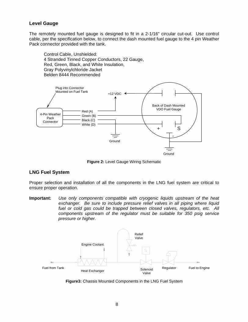
Level Gauge The remotely mounted fuel gauge is designed to fit in a 2-1/16” circular cut-out. Use control cable, per the specification below, to connect the dash mounted fuel gauge to the 4 pin Weather Pack connector provided with the tank.
Control Cable, Unshielded: 4 Stranded Tinned Copper Conductors, 22 Gauge, Red, Green, Black, and White Insulation, Gray Polyvinylchloride Jacket Belden 8444 Recommended
Plug into Connector Mounted on Fuel Tank
8
Figure 2: Level Gauge Wiring Schematic
LNG Fuel System Proper selection and installation of all the components in the LNG fuel system are critical to ensure proper operation. Important: Use only components compatible with cryogenic liquids upstream of the heat
exchanger. Be sure to include pressure relief valves in all piping where liquid fuel or cold gas could be trapped between closed valves, regulators, etc. All components upstream of the regulator must be suitable for 350 psig service pressure or higher.
Figure3: Chassis Mounted Components in the LNG Fuel System
Red (A) Green (B) Black (C) White (D)
+12 VDC
Back of Dash Mounted VDO Fuel Gauge
+
Ground
S -
4-Pin Weather Pack
Connector
Ground
Relief Valve
Engine Coolant
Fuel from Tank Regulator Fuel to Engine Solenoid Valve
Heat Exchanger

9
Fittings and Thread Sealants Taylor-Wharton recommends the use of stainless steel double ferrule compression fittings on all tube connections used for engine fuel lines. Parker A-lok, Swagelok, Hoke, and Hy-Lok are all suitable manufacturers. Nickel impregnated Teflon© tape should be used for all tapered pipe thread connections on the engine fuel lines. The tape is available from Taylor-Wharton; the part number is 9000-5005. Vent Stack The vent stack safely vents excess natural gas from the vehicle fuel tank primary relief valve. The vent stack connection on the fuel tank is a 1/2" outer diameter tube compression fitting. Use 1/2" outer diameter tube with a wall thickness of 0.049” for the vent stack. Run the tube to the top and back of the vehicle, away from the cab. The exhaust of the vent stack must be turned downward in order to prevent the accumulation of rain water. The vent stack must be provided with a drain to prevent the accumulation of water in the tube. The drain should connect to the vent stack at the lowest point. Use 1/8” tubing for the drain line. Run the drain downward and away from the vehicle exhaust. Warning: Water trapped within the vent stack may freeze preventing the primary relief from
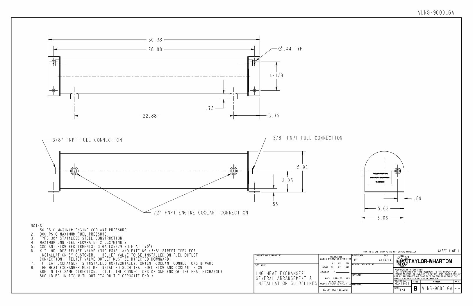
venting properly. Heat Exchanger The heat exchanger uses warm engine coolant to vaporize and warm the LNG fuel from the vehicle fuel tank. The heat exchanger should be bolted directly to the vehicle frame rails, as close as practical to the fuel tank. Position the heat exchanger horizontally with the engine coolant connections facing upward. The heat exchanger may also be positioned vertically. Connect the fuel tank outlet to the heat exchanger using 3/8” outer diameter stainless steel tubing with a wall thickness of 0.035”. This tubing run should be kept as short as possible. All tubing downstream of the heat exchanger should be 1/2" outer diameter stainless steel tube with a wall thickness of 0.049”. All tube bends should be smooth and free of kinks. Stainless steel compression fittings should be installed in the heat exchanger fuel connections. The inlet and outlet of the heat exchanger use 3/8” female tapered pipe thread. Engine coolant must be supplied to the heat exchanger in order for it to function. Coolant connections on the heat exchanger are 1/2" female tapered pipe thread. Use 5/8” inner diameter rubber hose to provide coolant to the heat exchanger. At full throttle, a minimum of 3gallons per minute of coolant must be provided to the heat exchanger in order to properly vaporize and warm the fuel. Important: The coolant hoses must be routed from the engine so that a constant flow is
provided. Do not install coolant hoses downstream of the cab heater control valve.
Important: Fuel and coolant must flow through the heat exchanger in the same direction; i.e.
the fuel inlet and coolant inlet should be on the same end of the heat exchanger.

Coolant Connections 1/2” Pipe Thread
Fuel Connection 3/8” Pipe Thread
(Identical Connection on Opposite End)
Figure 4: Heat Exchanger Heat Exchanger Relief Valve The heat exchanger must be equipped with a relief valve to protect it from over-pressurization in the event that liquid fuel is trapped between tank manual fuel shut-off valve and the engine pressure regulator. The relief valve should be installed downstream of the heat exchanger fuel outlet and upstream of the engine pressure regulator. A relief valve, suitable for cryogenic service, set to discharge at 300 psig is recommended. Warning: The outlet of the relief valve must be directed downward to prevent the
accumulation of debris, water, and ice. Over Pressure Regulator The engine fuel over pressure regulator provides natural gas to the engine at a steady pressure. This regulator is necessary as some engine components are not designed for the maximum pressure the tank may provide. The regulator should be mounted directly on the vehicle chassis. The regulator should not be supported by the connecting piping. The engine fuel pressure regulator must be rated for inlet pressures up to 350 psig. It should be adjustable over a minimum range of 80 to 125 psig. A lock nut on the adjustment screw should be featured. A regulator with 1/2” pipe size connections is recommended. Fuel Shut-Off Solenoid Valve The fuel shut-off solenoid valve is connected to the engine’s electrical system. The solenoid valve closes when the engine is turned off, disconnecting the engine from the rest of the fuel system. The fuel shut-off solenoid valve should be mounted directly on the vehicle chassis. The solenoid valve should not be supported by the connecting piping. A solenoid valve with 1/2” pipe size connections and 12 VDC actuation is recommended.
10

11
Taylor-Wharton Recommended Fuel System Components Taylor-Wharton recommends the following major components for the vehicle fuel system in addition to the fuel tank:
Component Taylor-Wharton Part Number Heat Exchanger with Relief Valve, 300 psig VLNG-9C00 Over Pressure Regulator VLNG-9C05 Over Pressure Regulator with Pressure Gauge and Mounting Bracket
VLNG-9C06
Fuel Shut-Off Solenoid Valve with Mounting Bracket
VLNG-9C10
Leak Test After installation and assembly of the fuel system components a leak test must be performed. Pressurize the fuel system to 200 psig using a pressure regulated nitrogen gas source. WARNING: Do not use compressed air for leak testing as it will create an explosive mixture
with the LNG fuel. Apply leak detector fluid to the all component seals and fitting joints. Large leaks instantly form large bubble clusters, while fine leaks produce white foam that builds up more slowly. Significant leaks must be repaired and retested before the fuel system is placed in service.

12
OPERATION Before operating, filling, or maintaining the LNG Vehicle Fuel Tank become familiar with the safety precautions in this manual, the referenced publications, and the LNG fuel station instruction manuals. Make certain all applicable provisions set forth in the Installation Section have been followed before placing a LNG Vehicle Fuel Tank into operation. Study this manual and the general arrangement drawing located in the back of this manual thoroughly. Know the location and function of all system components. CAUTION: Taylor-Wharton LNG Vehicle Fuel Tanks are not intended to contain fuels other
than liquefied natural gas (LNG). First Fill When an LNG vehicle fuel tank is filled for the first time, the inner vessel must be cooled to the temperature of LNG. The first fill procedure should be also be followed when a tank is returned to service after maintenance. WARNING: Wear insulated gloves and a face shield as explained in the Safety section of this
manual during filling. 1. Electrically ground the LNG vehicle fuel tank to the LNG filling station. 2. Remove the caps covering the fill and vent receptacles. Open the vehicle fuel tank door. 3. Visually check the valves, fittings, and tubes on the vehicle fuel tank. Do not attempt to fill a
tank with damage, missing components, or leaks. 4. Spray isopropyl alcohol on the fill and vent receptacles. (Alcohol cleans the receptacles and
repels moisture.) Wipe both receptacles with a clean cotton cloth. 5. Engage the station vent nozzle (if so equipped) with the vehicle fuel tank by engaging the
station vent nozzle with the receptacle pins and rotating the nozzle 90 degrees. 6. Observe the LNG vehicle tank pressure on the external pressure gauge. If the vehicle fuel
tank pressure is too high it may be necessary to vent the vehicle fuel tank back to the station tank. Consult the LNG fuel station manual for this procedure. The vehicle tank vent valve must be opened in order to vent. Close the vent valve once the desired pressure is reached.
7. Engage the station fill nozzle with the vehicle fuel tank fill receptacle. Be sure that the fill
nozzle is firmly attached and completely engaged. 8. Begin filling the vehicle tank per the LNG fuel station manual. Fill the vehicle fuel tank with
50 gallons of LNG as indicated on the LNG fuel station dispenser. 9. Vent the vehicle fuel tank pressure down to 100 psig by opening the vehicle fuel tank
vent valve. Close the vent valve when the proper pressure is reached. 10. Allow the vessel to cool for approximately 10 minutes. The vehicle fuel tank pressure
may rise significantly during this time. 11. If necessary, vent the vehicle fuel tank pressure down again by opening the vehicle fuel
tank vent valve. Close the vent valve when the proper pressure is reached.

13
12. Restart the filling station pump and completely filling the vehicle fuel tank per the fuel
station manufacturer instructions. 13. Be sure that the vehicle fuel tank vent valve is closed. Disconnect the vent nozzle and
the fill nozzle from the vehicle fuel tank. 14. Replace the caps for the fill and vent receptacles. Close the vehicle fuel tank door and
be sure the draw latch is secure. 15. Check the vehicle fuel gauge to be sure the tank has been completely filled. Normal Filling The normal filling procedure should be used when the inner vessel is cold and already contains some amount of LNG. WARNING: Wear insulated gloves and a face shield as explained in the Safety section of this
manual during filling. 1. Electrically ground the LNG vehicle fuel tank to the LNG filling station. 2. Remove the caps covering the fill and vent receptacles. Open the vehicle fuel tank door. 3. Visually check the valves, fittings, and tubes on the vehicle fuel tank. Do not attempt to fill a
tank with damage, missing components, or leaks. 4. Spray isopropyl alcohol on the fill and vent receptacles. (Alcohol cleans the receptacles and
repels moisture.) Wipe both receptacles with a clean cotton cloth. 5. Engage the station vent nozzle (if so equipped) with the vehicle fuel tank by engaging the
station vent nozzle with the receptacle pins and rotating the nozzle 90 degrees. 6. Observe the LNG vehicle tank pressure on the external pressure gauge. If the vehicle fuel
tank pressure is too high it may be necessary to vent the vehicle fuel tank back to the station tank. Consult the LNG fuel station manual for this procedure. The vehicle tank vent valve must be opened in order to vent. Close the vent valve once the desired pressure is reached.
7. Engage the station fill nozzle with the vehicle fuel tank fill receptacle. Be sure that the fill
nozzle is firmly attached and completely engaged. 8. Begin the filling the vehicle tank per the LNG fuel station manual. Most stations are
equipped with an automatic fill stop that will stop the fill when the vehicle fuel tank is completely full.
9. Be sure that the vehicle fuel tank vent valve is closed. Disconnect the vent nozzle and
the fill nozzle from the vehicle fuel tank. 10. Replace the caps for the fill and vent receptacles. Close the vehicle fuel tank door and
be sure the draw latch is secure. 11. Check the vehicle fuel gauge to be sure the tank has been completely filled.

14
Normal Operation During normal operation the vent valve and drain valve should be completely closed. The Manual fuel shut-off valve should be completely open. The tank will gradually build pressure when the vehicle is not being driven. Eventually the primary relief valve may open in order to reduce the vehicle fuel tank pressure. This is normal. The primary relief valve will automatically close once the tank pressure has been reduced slightly.

15
MAINTENANCE Routine inspections of the LNG fuel system are recommended. Keep a permanent log of all inspections and repairs performed. Such a log can be valuable in evaluating performance and scheduling maintenance.
Date Nature of Work (Describe in Full) Remarks Servicemen's Signature
Figure 5: Inspection and Repair Log (Sample Form) Always observe the safety precautions at the front of this manual and follow the instructions given in this section. Do not allow unqualified persons to attempt repairs on this equipment. Refer to the Trouble-Remedy Guide in this manual for assistance in troubleshooting. WARNING: Before working on the LNG fuel system or storing a vehicle in-doors completely
drain the fuel tank and purge it with nitrogen gas. The fuel tank and fuel system must be completely depressurized before maintenance may begin.
Draining the Tank If possible, the vehicle tank should be drained when it is less than ¼ full. Attempt to schedule draining of the tank at the end of the vehicle route, before refueling. WARNING: The tank must be drained outdoors in an open area away from open flame,
electrical equipment, and other ignition sources. WARNING: Do not dispose of LNG by dumping it to the atmosphere. The boiling liquid will
create a flammable atmosphere. 1. Make sure the vehicle tank drain valve is completely closed. 2. Remove the wire retaining the vehicle tank drain valve handle and remove the plug. 3. Install a 3/8” male pipe thread by 1/2" outer diameter tube size 45 degree flare fitting,
made of brass, into the vehicle tank drain connection. (Taylor-Wharton P/N 7355-4712)
16
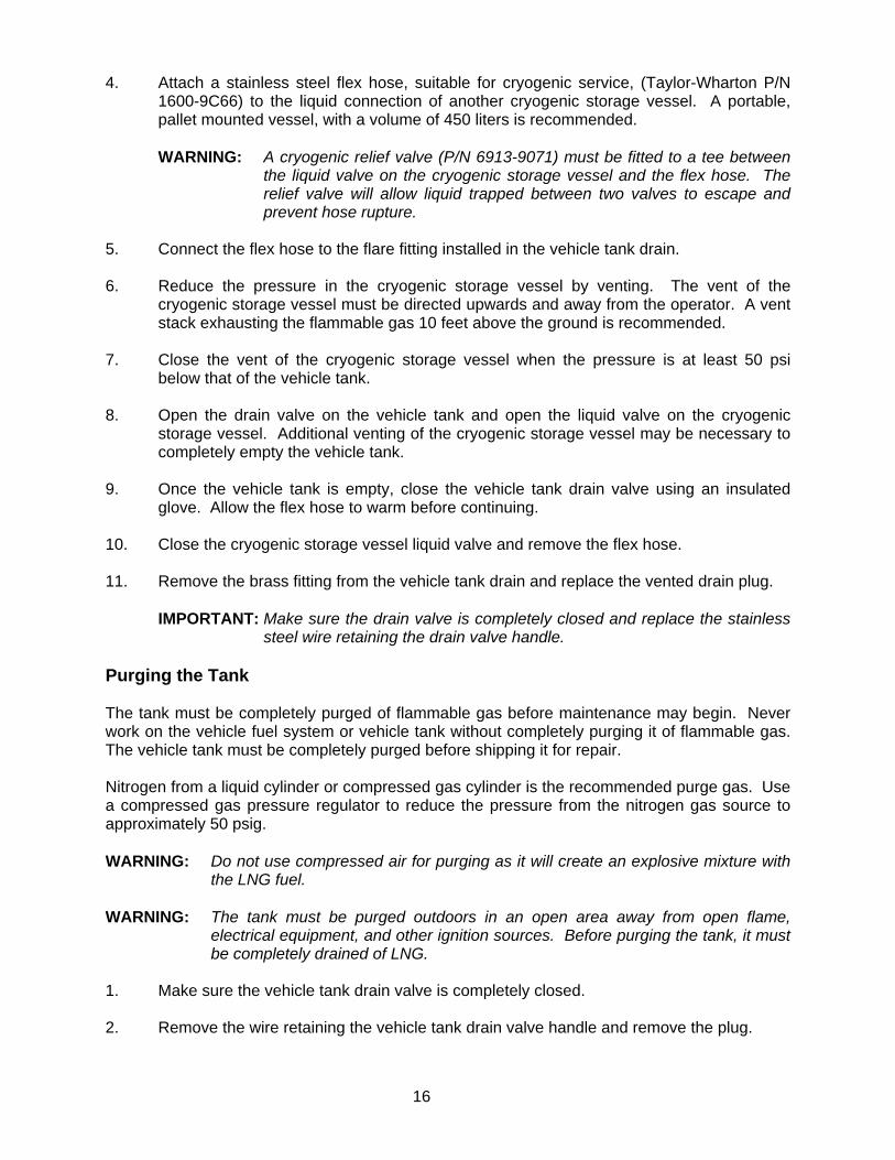
4. Attach a stainless steel flex hose, suitable for cryogenic service, (Taylor-Wharton P/N 1600-9C66) to the liquid connection of another cryogenic storage vessel. A portable, pallet mounted vessel, with a volume of 450 liters is recommended.
WARNING: A cryogenic relief valve (P/N 6913-9071) must be fitted to a tee between
the liquid valve on the cryogenic storage vessel and the flex hose. The relief valve will allow liquid trapped between two valves to escape and prevent hose rupture.
5. Connect the flex hose to the flare fitting installed in the vehicle tank drain. 6. Reduce the pressure in the cryogenic storage vessel by venting. The vent of the
cryogenic storage vessel must be directed upwards and away from the operator. A vent stack exhausting the flammable gas 10 feet above the ground is recommended.
7. Close the vent of the cryogenic storage vessel when the pressure is at least 50 psi
below that of the vehicle tank. 8. Open the drain valve on the vehicle tank and open the liquid valve on the cryogenic
storage vessel. Additional venting of the cryogenic storage vessel may be necessary to completely empty the vehicle tank.
9. Once the vehicle tank is empty, close the vehicle tank drain valve using an insulated
glove. Allow the flex hose to warm before continuing. 10. Close the cryogenic storage vessel liquid valve and remove the flex hose. 11. Remove the brass fitting from the vehicle tank drain and replace the vented drain plug.
IMPORTANT: Make sure the drain valve is completely closed and replace the stainless steel wire retaining the drain valve handle.
Purging the Tank The tank must be completely purged of flammable gas before maintenance may begin. Never work on the vehicle fuel system or vehicle tank without completely purging it of flammable gas. The vehicle tank must be completely purged before shipping it for repair. Nitrogen from a liquid cylinder or compressed gas cylinder is the recommended purge gas. Use a compressed gas pressure regulator to reduce the pressure from the nitrogen gas source to approximately 50 psig. WARNING: Do not use compressed air for purging as it will create an explosive mixture with
the LNG fuel. WARNING: The tank must be purged outdoors in an open area away from open flame,
electrical equipment, and other ignition sources. Before purging the tank, it must be completely drained of LNG.
1. Make sure the vehicle tank drain valve is completely closed. 2. Remove the wire retaining the vehicle tank drain valve handle and remove the plug.

17
3. Vent the vehicle tank pressure down to atmospheric pressure (0 psig indicated on the vehicle tank pressure gauge) through the drain valve.
4. Attach a vent nozzle (available from Macro Technologies, P/N 11175) to the vehicle tank
vent receptacle. The vent nozzle will open the vehicle tank vent receptacle and allow gas to escape to the atmosphere.
Macro Technologies, Inc. 11815 - 124th Ave NE Kirkland, WA 98034 tel: (425) 825-8100 fax: (425) 825-8101 www.macrotechnologies.com 5. Connect the nitrogen purge gas source to the vehicle tank drain connection. 6. Allow nitrogen to flow into the vehicle tank and out of the vent nozzle. 7. Use a portable methane detector to monitor the gas exiting the vent nozzle. Purge the
tank until there are no detectable amounts of methane in the vent nozzle gas stream. 8. Remove the vent nozzle and pressurize the tank to 50 psi. Disconnect the nitrogen
purge gas. 9. Allow the tank to sit pressurized for a half hour and reconnect the vent nozzle. Use the
portable methane detector to check the gas exiting the nozzle for methane. If any methane is detected repeat the purge procedure.
10. Store the vehicle tank with 20 psig of pressure indicated on the pressure gauge.
Replace the vented drain plug in the drain connection.
IMPORTANT: Make sure the drain valve is completely closed and replace the stainless steel wire retaining the drain valve handle.
11. The tank purge procedure is complete. It is now safe to work on the tank. Hand Valves If the hand valves leak or are difficult to close completely they should be rebuilt. Rebuild kits (P/N 6914-4025) are available from Taylor-Wharton. Detailed instructions are provided with the rebuild kit. Be sure the all components are clean and free of debris before reassembly. Relief Valves If the relief valves fail to operate properly they must be replaced. The relief valves cannot be repaired or rebuilt. Indications of improper operation include opening or weeping at pressures significantly below the set to discharge pressure. Check Valves If the check valves fail to operate properly they must be replaced. The check valves cannot be repaired or rebuilt.

18
A malfunctioning fill check valve may leak slightly back through the fill connection. It may also cause filling to occur slowly. A slow fill rate may cause the fueling station to automatically shut-down before the tank is completely full. A malfunctioning vapor withdrawal back pressure check valve may not close properly. This may cause lower than desirable tank pressures. When reinstalling the check valves, be sure the flow arrow is pointing in the correct direction. The general arrangement drawing at the back of this manual indicates the proper flow direction. Excess Flow Valve If the excess flow valve fails to operate properly it must be replaced. The excess flow valve cannot be repaired or rebuilt. Indications of improper operation include tripping (closing) during normal engine operation. The excess flow valve can be reset by closing the manual fuel shut-off valve. After a few seconds the excess flow valve will reopen. The manual fuel shut-off valve may now be reopened. Tank Pressure Control Regulator The tank pressure control regulator may be adjusted without removal from the LNG vehicle tank. The following procedure describes the process: 1. Loosen the lock nut on the adjusting screw on the top of the regulator. 2. Raise the setpoint by turning the adjusting screw clockwise; lower the setpoint by turning
the screw counterclockwise. One quarter turn will adjust the pressure approximately 6 psi.
3. Tighten the lock nut on the adjusting screw of the regulator. Note that the pressure of the tank will not suddenly change when the regulator is adjusted. The pressure control circuit serves to reduce excessive tank pressure while the engine is running. It will not directly increase the tank pressure. However, increasing the regulator setting will result in higher tank operating pressures after the vehicle tank is refilled or allowed to naturally build pressure over time. For more accurate adjustment it is recommended that the pressure building regulator be removed from the system. A regulator bench adjustment fixture should be used. The figure below shows a typical setup.
19
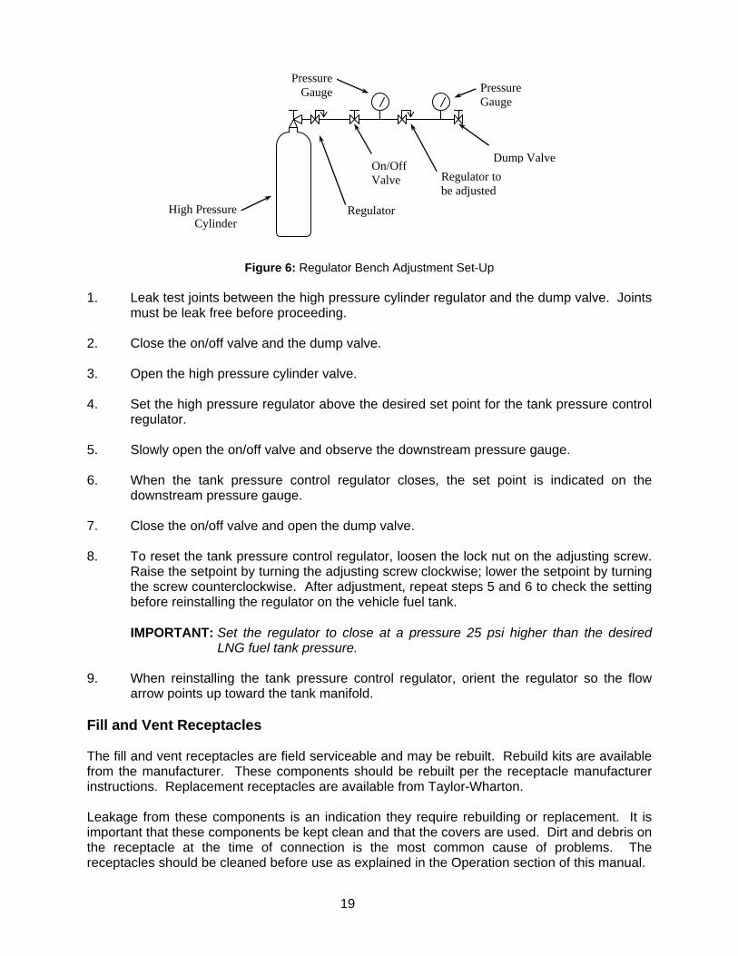
Figure 6: Regulator Bench Adjustment Set-Up
1. Leak test joints between the high pressure cylinder regulator and the dump valve. Joints
must be leak free before proceeding. 2. Close the on/off valve and the dump valve. 3. Open the high pressure cylinder valve. 4. Set the high pressure regulator above the desired set point for the tank pressure control
regulator. 5. Slowly open the on/off valve and observe the downstream pressure gauge. 6. When the tank pressure control regulator closes, the set point is indicated on the
downstream pressure gauge. 7. Close the on/off valve and open the dump valve. 8. To reset the tank pressure control regulator, loosen the lock nut on the adjusting screw.
Raise the setpoint by turning the adjusting screw clockwise; lower the setpoint by turning the screw counterclockwise. After adjustment, repeat steps 5 and 6 to check the setting before reinstalling the regulator on the vehicle fuel tank.
IMPORTANT: Set the regulator to close at a pressure 25 psi higher than the desired
LNG fuel tank pressure. 9. When reinstalling the tank pressure control regulator, orient the regulator so the flow
arrow points up toward the tank manifold. Fill and Vent Receptacles The fill and vent receptacles are field serviceable and may be rebuilt. Rebuild kits are available from the manufacturer. These components should be rebuilt per the receptacle manufacturer instructions. Replacement receptacles are available from Taylor-Wharton. Leakage from these components is an indication they require rebuilding or replacement. It is important that these components be kept clean and that the covers are used. Dirt and debris on the receptacle at the time of connection is the most common cause of problems. The receptacles should be cleaned before use as explained in the Operation section of this manual.
Pressure Gauge Pressure
Gauge
High Pressure Cylinder
Regulator
Regulator to be adjusted
Dump Valve On/Off Valve
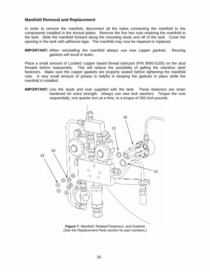
Manifold Removal and Replacement In order to remove the manifold, disconnect all the tubes connecting the manifold to the components installed in the shroud plates. Remove the five hex nuts retaining the manifold to the tank. Slide the manifold forward along the mounting studs and off of the tank. Cover the opening in the tank with adhesive tape. The manifold may now be repaired or replaced. IMPORTANT: When reinstalling the manifold always use new copper gaskets. Reusing
gaskets will result in leaks. Place a small amount of Loctite© copper based thread lubricant (P/N 9000-5100) on the stud threads before reassembly. This will reduce the possibility of galling the stainless steel fasteners. Make sure the copper gaskets are properly seated before tightening the manifold nuts. A very small amount of grease is helpful in keeping the gaskets in place while the manifold is installed. IMPORTANT: Use the studs and nuts supplied with the tank. These fasteners are strain
hardened for extra strength. Always use new lock washers. Torque the nuts sequentially, one quarter turn at a time, to a torque of 350 inch-pounds.
18
20 19
21
22
Figure 7: Manifold, Related Fasteners, and Gaskets (See the Replacement Parts section for part numbers.)
20

Liquid Level Gauge and Sender If the liquid level gauge is found to be operating improperly, inspect all the connections and wiring between the tank mounted level sender and the dash mounted fuel gauge. Review the Installation section of this manual to be sure the wiring is properly installed. The internal level sensor may be checked by measuring capacitance of the device and checking it for electrical shorts. A multi-meter capable of measuring capacitance will be required. Remove the cover of the level sender enclosure. A single conductor wire runs from the level sensor inside the tank to the level sender. Remove the shrink tubing from around the wire running from the top of the enclosure. Cut the wire at the connection and strip back the insulation a ¼” on both sides of the cut. With the multi-meter set to measure capacitance, connect one lead to the wire running from the top of the enclosure. Connect the other lead to the bracket supporting the liquid level sender. The multi-meter should read between 450 and 500 pico farads when the tank is completely empty of fuel (for the 26” O.D. tank). A reading outside of this range indicates a problem with the wiring or the internal level sensor. Switch the multi-meter to check for electrical shorts. Damage to the wire insulation is the most probable cause for an electrical short. If a problem can be found with the wire inside the tube connecting the tank to the level sender or the pressure feed-thru it may be repaired. An unlikely internal failure of the liquid level sender or wiring internal to the tank cannot be repaired and the tank must be replaced. If no fault is found with the internal level sensor or wiring, replace the level sender and the dash mounted fuel gauge. Solder the connections for the single conductor wire running from the tank to the level sender. Use heat shrink tube over the connections to prevent electrical shorts.
13.7
13.1
13.4
13.6
13.5
Figure 8: Liquid Level Sender Assembly (See the Replacement Parts section for part numbers.)
Leak Test After making repairs, leak test all valves and piping joints that were reconnected. Pressurize the tank to 200 psig using nitrogen gas. Never pressurize the tank with compressed air. Apply leak detector fluid to the test surfaces. Large leaks instantly form large bubble clusters, while fine leaks produce white foam that builds up more slowly. Significant leaks must be repaired and retested before the fuel tank is returned to service. 21

22
Checking Vacuum This product is carefully designed, manufactured, and tested with every effort made to eliminate vacuum space leakage. An absorbent material (molecular sieve) and a reactive chemical (palladium oxide) are sealed inside the vessel jacket to help maintain the vacuum over a long period of time. However, some vacuum deterioration may be experienced after years of service due to out-gassing of materials inside the vacuum space. Hold Time Test To determine if vacuum deterioration has occurred, a hold time test may be performed as a preliminary evaluation. A hold time test gives an approximate indication of the condition of the vacuum and insulation system. This test may be performed without removing the tank from the vehicle. The tank should be cold and contain some liquid at the start of this procedure. 1. Fill the tank with LNG to a normal full shut-off. Vent the tank to 100 psig. Note the
reading on the dash mounted level gauge and the time. 2. Park the vehicle and allow it to sit for at least one hour. Record the tank pressure from
the pressure gauge mounted on the tank shroud. Record the time of day. 3. Do not run the vehicle for 24 hours. Record the tank pressure after the end of this time
period. Record the time of day. 4. Calculate the average rate of pressure rise using the following formula: Pressure (Step 3) – Pressure (Step 2) Rate of Pressure Rise = ———————————————— Time Between Step 2 and 3 in Hours A rate of pressure rise exceeding 2.4 psi per hour indicates that the vessel may have a vacuum problem. A tank failing this test may need to be returned to the factory for evaluation. Note: Due to the limited accuracy of the pressure gauge and other factors the results of this
test alone do not constitute a warranty claim. Taylor-Wharton or an approved service center must perform an N.E.R. test to evaluate tanks returned for warranty repair.
Condensation or even ice on the vessel jacket is another indication of a vacuum problem. Note that some icing or condensation is normal around the piping connections of the vessel and on the center of the head opposite the piping. Condensation may also occur on the vessel’s outer surface as a result of high humidity. If it has been determined that the vessel may have a vacuum problem, it may be necessary to repair or replace the vessel. Contact Taylor-Wharton customer service at 1-800-898-2657 for assistance. Have the tank serial number available. Nitrogen N.E.R. Test A more precise method of determining the condition of the vacuum and insulation is a normal evaporation rate test, or N.E.R. test, performed with liquid nitrogen. This method is used by Taylor-Wharton to evaluate warranty claims on returned tanks. (A nitrogen N.E.R. test is used, as apposed to LNG, due to nitrogen’s high density and low heat of vaporization.)

23
1. Drain the tank and remove it from the vehicle as explained in the maintenance section of this manual. Place the tank in the shipping cradle provided with the tank for ease of handling.
2. Place the tank (and the shipping cradle) on a weight scale. The scale should have a
plus/minus 0.2 pound accuracy and a 1,000 pound or greater capacity. Make sure the manual fuel shut-off valve is closed.
3. Fill the tank through the drain valve with 200 pounds of liquid nitrogen. While filling, and
throughout the test, leave the vent valve open. Engage a Macro vent nozzle with the tank vent receptacle (if so equipped) and allow the tank to vent to atmosphere during the entire test.
4. Allow the tank to stabilize for 24 hours. Record the weight, time, and date. 5. Allow the tank to sit, undisturbed, for 48 hours. Record the weight, time, and date. The following calculation will provide the actual normal evaporation rate in pounds per day for liquid nitrogen. Weight (Step 4) – Weight (Step 5) Daily N.E.R. = ———————————————— x 24 Time between Step 3 and 4 in hours The following chart shows nitrogen N.E.R. requirements for different tanks. N.E.R. test results exceeding those listed in the chart indicate a problem with the vacuum or insulation system.
Vacuum and Thermal Performance Daily N.E.R. Specification, Liquid Nitrogen,
pounds per day Model 0 to 3 Years
(from date of shipment) 3 to 5 Years
(from date of shipment) After 5 Years
(from date of shipment) LNG-119V 12.0 13.4 15.0 LNG-72V 10.0 11.1 12.5
Note: The specifications shown in the chart above, and only those shown above, may be
used in determination of warranty claims for the indicated models.

24
Trouble-Remedy Guide Trouble Possible Cause Remedy
a. Fuel tank is empty. a. Refill the tank. b. Tank pressure control
regulator is out of adjustment. b. Adjust or replace regulator.
c. Piping leaks to atmosphere. c. Leak test and repair piping.
1. Tank pressure is too low.
d. Primary or secondary relief valve is opening at too low a pressure.
d. Replace the primary or secondary relief valve.
a. Vehicle has not been run lately.
a. No remedy, this is normal operation.
2. Tank pressure is too high and the primary relief valve is opening occasionally. b. Vessel vacuum has
deteriorated. b. Perform vacuum test. Have
vessel repaired and re-evacuated.
a. Level sender is out of adjustment or operating improperly.
a. Replace level sender.
b. Wiring is faulty. b. Check wiring from fuel gauge to sender. Repair wiring.
3. Fuel gauge does not appear to read correctly.
c. Dash mounted fuel gauge is malfunctioning.
c. Replace dash mounted fuel gauge.
a. Manual fuel shut-off valve is not completely open.
a. Completely open manual fuel shut-off valve.
b. Vehicle mounted engine pressure regulator requires adjustment or replacement.
b. Adjust or replace engine pressure control regulator.
c. Excess flow valve is malfunctioning and closing prematurely.
c. Replace excess flow valve.
4. Tank pressure is adequate however fuel pressure at the engine is too low.
d. Fuel lines, fittings, or other fuel system components are undersized.
d. Consider up-sizing fuel lines, fittings, or components.

Replacement Parts Order replacement parts from Taylor-Wharton Customer Service (1-800-898-2657). To identify components refer to the general arrangement drawing in the appendix of the manual.
Replacement Parts List
ITEM PART NUMBER DESCRIPTION 1 85441395 Valve, Check, 1/2" FNPT, Brass 2.1 4515-9610 Receptacle, LNG, Carter, 3/4" FNPT 2.2 4515-9611 Cover for Receptacle, Carter 2.3 4515-9615 Receptacle, LNG, Parker, 1" FNPT 2.4 4515-9616 Cover for Receptacle, Parker 3 6913-9085 Relief Valve, 1/4” MNPT, Brass, 230 PSIG 4 587695 Relief Valve, 1/4” MNPT, Brass, 350 PSIG 5.1 6914-4020 Valve, 3/8” FNPT x 3/8” Pipe Stub 5.2 6914-4025 Valve Repair Kit 6 4556-0091 Bulkhead Union, 1/2" ODT, S316 7 1750-9C04 Regulator, 1/4" FNPT, Set at 125 PSIG 8 6914-4020 Valve, 3/8” FNPT x 3/8” Pipe Stub 9 V119-9C08 Drain Plug, 3/8”, Drilled 10 6914-4020 Valve, 3/8” FNPT x 3/8” Pipe Stub 11 8545-2099 Excess Flow Valve, 3/8” ODT x 3/8” MNPT, S.S. 12 V119-9C24 Bulkhead Fitting, Drilled 13 Level Gauge Parts: 13.1 5741-0020 Sender, LNG Level, 26” OD Tank 13.2 5741-0050 Fuel Gauge, Dash Mounted 13.3 5741-0051 Connector, 4-Pin Male 13.4 4930-0080 O-Ring, 1/2"ID X 11/16"OD 13.5 5741-0100 Pressure Feed-Thru 13.6 4116-7000 Nut, 1/4" NPT 13.7 41735810 Washer, 9/16" ID 14.1 5714-3495 Pressure Gauge, 0-400 PSIG 14.2 5714-3496 Pressure Gauge Mount, 2-1/2” 15 8544-1385 Check Valve, 3/8” ODT, Type 316 16 8544-1385 Check Valve, 3/8” ODT, Type 316 17 4515-9600 Quick Connector, Macro, 3/8” MNPT 18 4169-4000 Stud, 5/16"-24, Type 304SH 19 4116-1750 Nut, Hex, 5/16"-24, Type 304SH 20 6460-2100 Lock-washer, 5/16", Stainless Steel 21 4916-0100 Gasket, Copper, 3/4” OD 22 4916-0105 Gasket, Copper, 1” OD 23 V119-9C23 Decal Kit, LNG Vehicle Tank
25
26
APPENDIXES Appendix 1 – LNG Vehicle Tank General Arrangement Appendix 2 – LNG Heat Exchanger General Arrangement


4075 Hamilton Blvd. Theodore, Alabama 36582 U.S.A. Telephone (251) 443-8680 Fax (251) 443-2250 In U.S. and Canada: (800) TW TANKS (898-2657
Manual P/N 7950-8359 Publication # TW-359 ©2004 Harsco Corporation