load balancing microsoft remote desktop services · accessing the web user interface ... or...
TRANSCRIPT

Load Balancing Microsoft Remote Desktop Services
Deployment Guidev2.0.0
Copyright © Loadbalancer.org

Table of Contents
1. About this Guide.........................................................................................................................................4
2. Loadbalancer.org Appliances Supported..........................................................................................4
3. Loadbalancer.org Software Versions Supported............................................................................4
4. Microsoft Windows Versions Supported...........................................................................................4
5. Remote Desktop Services (RDS)............................................................................................................5Introduction............................................................................................................................................................................. 5
Role Services............................................................................................................................................................................ 5
Role Service – Server Location / Collocation...........................................................................................................6
RDS Installation – Windows 2008 R2.............................................................................................................................. 6
RDS Installation – Windows 2012 & 2016...................................................................................................................... 7
Choosing Between VM-Based & Session-Based Desktop Deployments.........................................................9
The Standard Deployment – Recommended by Microsoft.................................................................................9
RDS Configuration – Deployment Properties............................................................................................................. 11
High Availability Settings................................................................................................................................................ 11
Certificates.......................................................................................................................................................................... 11
6. Load Balancing RDS - Concepts.........................................................................................................12What About the built-in Load Balancing mechanism?............................................................................................12
Which Role Services Should I Load Balance?.............................................................................................................. 13
Load Balanced Ports & Services....................................................................................................................................... 13
Persistence (Server Affinity) Requirements & Options.............................................................................................. 13
MS Session Broker Persistence..................................................................................................................................... 14
Source IP Persistence...................................................................................................................................................... 15
RDP Client Cookie Persistence.................................................................................................................................... 15
Load Balancer Deployment Mode.................................................................................................................................. 15
Deploying the Load Balancer – VIP Location............................................................................................................. 16
7. Remote Desktop Services – Load Balancing Scenarios.............................................................18Scenario 1 - Load Balancing Web Access Servers.....................................................................................................18
Scenario 2a - Load Balancing Connection Brokers with Session Hosts............................................................19
Scenario 2b - Load Balancing Connection Brokers with Virtualization Hosts................................................20
Scenario 3 - Load Balancing Gateways......................................................................................................................... 21
Scenario 4 - Load Balancing Stand alone Session Hosts........................................................................................22
Scenario 5 - Load Balancing Session Hosts when Deployed with Connection Broker................................23
8. Loadbalancer.org Appliance – the Basics.......................................................................................26Virtual Appliance Download & Deployment...............................................................................................................26
Initial Network Configuration.......................................................................................................................................... 26
Accessing the Web User Interface (WebUI)................................................................................................................. 27
HA Clustered Pair Configuration.................................................................................................................................... 28
9. Load Balancing Web Access Servers (Scenario 1)........................................................................29RDS Installation & Configuration.................................................................................................................................... 29
Appliance Configuration................................................................................................................................................... 29
Setting up the Virtual Service (VIP)............................................................................................................................. 29
Setting up the Real Servers (RIPs)............................................................................................................................... 30
Testing & Verification......................................................................................................................................................... 30
Microsoft RDS Deployment Guide v2.0.0

10. Load Balancing Connection Brokers (Scenario's 2a & 2b)......................................................30RDS Installation & Configuration.................................................................................................................................... 30
Appliance Configuration.................................................................................................................................................... 32
Setting up the Virtual Service (VIP)............................................................................................................................. 32
Setting up the Real Servers (RIPs)................................................................................................................................ 33
Applying the new Layer 7 Settings.............................................................................................................................. 33
Testing & Verification.......................................................................................................................................................... 33
11. Load Balancing Gateways (Scenario 3)..........................................................................................34RDS Installation & Configuration.................................................................................................................................... 34
Appliance Configuration.................................................................................................................................................... 35
Using 2 VIPs – One for TCP, One for UDP............................................................................................................... 36
Using a Single Layer 4 SNAT Mode VIP for Both TCP & UDP............................................................................38
Testing & Verification.......................................................................................................................................................... 39
12. Load Balancing Standalone Session Hosts (Scenario 4)..........................................................39RDS Installation & Configuration.................................................................................................................................... 39
Appliance Configuration................................................................................................................................................... 40
Setting up the Virtual Service (VIP)............................................................................................................................. 40
Setting up the Real Servers (RIPs)................................................................................................................................ 41
Applying the new Layer 7 Settings.............................................................................................................................. 41
Testing & Verification.......................................................................................................................................................... 41
13. Load Balancing Session Hosts Deployed with Connection Broker (Scenario 5)............41RDS Installation & Configuration.................................................................................................................................... 41
Appliance Configuration................................................................................................................................................... 44
Using Layer 4 SNAT Mode (Required for UDP Transport)...................................................................................44
Using Layer 7 SNAT Mode (Required for Token Redirection Mode)................................................................46
Testing & Verification.......................................................................................................................................................... 47
14. Technical Support.................................................................................................................................47
15. Further Documentation.......................................................................................................................47
16. Conclusion...............................................................................................................................................47
17. Appendix...................................................................................................................................................481 - Load Balancer Deployment Modes......................................................................................................................... 48
Layer 4 DR Mode.............................................................................................................................................................. 48
Layer 4 NAT Mode........................................................................................................................................................... 49
Layer 4 SNAT Mode......................................................................................................................................................... 50
Layer 7 SNAT Mode.......................................................................................................................................................... 51
3 - Server Feedback Agent................................................................................................................................................ 52
4 - Configuring Windows 2008 R2 for Routing Token Redirection Mode.......................................................54
5 - Clustered Pair Configuration – Adding a Slave Unit..........................................................................................55
6 - Company Contact Information................................................................................................................................ 58
Microsoft RDS Deployment Guide v2.0.0

About this Guide
1. About this GuideThis guide details the steps required to configure a load balanced Microsoft Remote Desktop Services (RDS) environment utilizing Loadbalancer.org appliances. It covers the configuration of the load balancers and also any Microsoft Remote Desktop Services configuration changes that are required to enable load balancing. The guide focuses on Windows 2012 and later, although reference is made to 2008 R2 where appropriate.
For more information about initial appliance deployment, network configuration and using the Web User Interface (WebUI), please also refer to the relevant Administration Manual:
• v7 Administration Manual
• v8 Administration Manual
2. Loadbalancer.org Appliances SupportedAll our products can be used with Remote Desktop Services. The complete list of models is shown below:
Discontinued Models Current Models *
Enterprise R16 Enterprise R20
Enterprise VA R16 Enterprise MAX
Enterprise VA Enterprise 10G
Enterprise R320 Enterprise Ultra
Enterprise VA R20
Enterprise VA MAX
Enterprise AWS **
Enterprise AZURE **
* For full specifications of these models please refer to: http://www.loadbalancer.org/products/hardware
** Some features may not be supported, please check with Loadbalancer.org support
3. Loadbalancer.org Software Versions Supported
• V7.6.4 and later
4. Microsoft Windows Versions Supported
• Windows 2008 R2 and later
Microsoft RDS Deployment Guide v2.0.0
Page 4

Remote Desktop Services (RDS)
5. Remote Desktop Services (RDS)
INTRODUCTIONRemote Desktop Services can be used to provide:
• Access to full remote desktops- this can be either session-based or VM-based and can be providedlocally from PC's, laptops & thin clients or from virtually anywhere using mobile devices.
• Access to applications - RemoteApp can be used to provide users with access to applications running on RD Session Host servers. These applications look and feel just like locally installed programs.
• Secure remote access - Remote Desktop Gateway (RD Gateway) can be used to provide secure remote access to desktops and applications without the need for a VPN.
ROLE SERVICESThe following role services can be deployed as part of the RDS role.
Role Service Purpose
RD Virtualization Host This role service integrates with the Hyper-V role in Windows Server 2012 R2 to provide VMs that can be used as virtual desktops. The RD Virtualization Host role service also monitors and reports on established client sessions to the RD Connection Broker role service. This role service is responsible for managing theVMs that function as pooled and personal virtual desktops. If VMs are in a saved state, the RD Virtualization Host role service starts the VMs to prepare them for auser connection. For pooled virtual desktops, the RD Virtualization Host role service reverts the VMs to their initial state when users sign out.
RD Virtualization Host role service is required in a VM-based deployment of RDS.
RD Session Host This role service configures a server to provide session-based desktops and applications. Users can connect to an RD Session Host server and then run applications and use the network resources that the RD Session Host offers.
RD Session Host is a required role service in a session-based desktop deployment of RDS.
RD Connection Broker This role service manages connections to RemoteApp programs and virtual desktops, and it directs client connection requests to an appropriate endpoint. The RD Connection Broker role service also provides session re-connection andsession load balancing. For example, when a user disconnects from a session and later establishes a connection, the RD Connection Broker role service ensures that the user reconnects to his or her existing session.
RD Connection Broker is mandatory in all RDS deployments.
RD Web Access This role service provides a web-based interface to RemoteApp programs, session-based virtual desktops, or VM-based virtual desktops. A webpage provides each user with a customized view of all RDS resources that have been published to that user. This role service supports organizing resources in
Microsoft RDS Deployment Guide v2.0.0
Page 5

Remote Desktop Services (RDS)
folders, which enables administrators to group remote applications in a logical manner. It also publishes available RDS resources in an RDWeb feed, which can integrate with the Start screen on client devices.
RD Web Access is a mandatory role service for each RDS deployment.
RD Licensing This role service manages RDS client access licenses (RDS CALs) that are required for each device or user to connect to an RD Session Host server. You use RD Licensing to install, issue, and track RDS CAL availability on an RD Licensing server.
You are not required to install this role service during an initial RDS deployment,but an RDS deployment without proper licensing ceases to function after 120 days.
RD Gateway This role service allows authorized remote users to connect securely to RemoteApp programs and virtual desktops from outside the organization over the Internet. An RD Gateway server acts as a proxy for external users to connect to internal RDS resources. To increase compatibility with firewalls in public locations such as hotels, RDP traffic is encapsulated in Hypertext Transfer Protocol Secure (HTTPS) packets. Access is controlled by configuring Remote Desktop connection authorization policies (RD CAPs) and Remote Desktop resource authorization policies (RD RAPs). An RD CAP specifies who is authorized to make a connection, and an RD RAP specifies to which resources authorized users may connect.
RD Gateway is an optional role service.
For much more information about RDS please refer to this URL.
Note:
It is possible to deploy just RD Session Host Servers & a Loadbalancer.org appliance without the complete RDS infrastructure. If you only require the ability to provide multiple full desktops thenthis approach may be appropriate. For more information, please refer to load balancing scenario4 on page 22.
ROLE SERVICE – SERVER LOCATION / COLLOCATIONDepending on the number of users and the server specifications, role services can be collocated, althoughMicrosoft recommends that whenever possible the Session Host and Connection Broker role services should be kept on dedicated servers. Typically, RD Gateway and RD Web Access are candidates for collocation.
RDS INSTALLATION – WINDOWS 2008 R2Installation of RDS under Windows 2008 R2 uses the traditional role/service concept. The RDS infrastructure must be built by manually installing the required services on the various servers to build the desired infrastructure. The screenshot below shows the initial service selection screen for installing RDS under Windows 2008 R2.
Microsoft RDS Deployment Guide v2.0.0
Page 6
Remote Desktop Services (RDS)
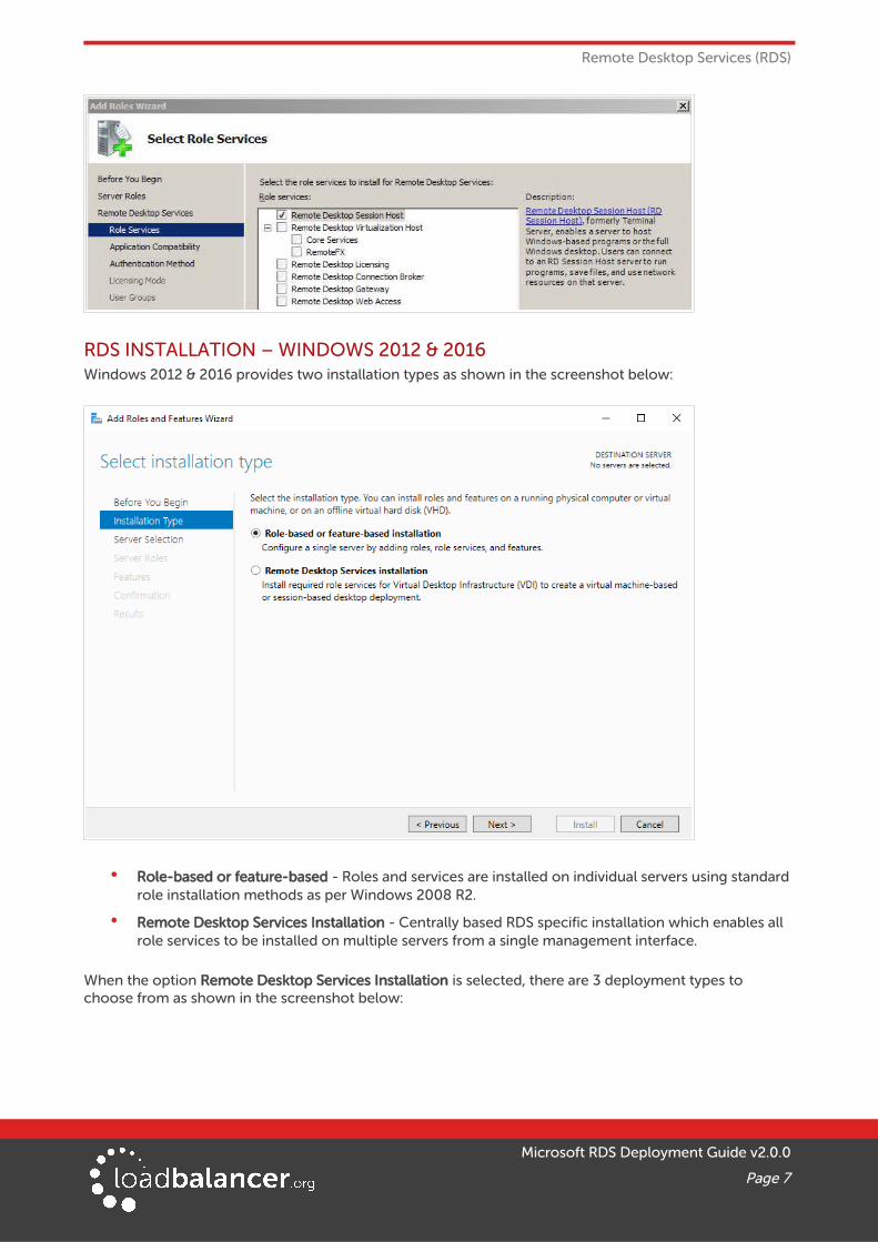
RDS INSTALLATION – WINDOWS 2012 & 2016Windows 2012 & 2016 provides two installation types as shown in the screenshot below:
• Role-based or feature-based - Roles and services are installed on individual servers using standard role installation methods as per Windows 2008 R2.
• Remote Desktop Services Installation - Centrally based RDS specific installation which enables all role services to be installed on multiple servers from a single management interface.
When the option Remote Desktop Services Installation is selected, there are 3 deployment types to choose from as shown in the screenshot below:
Microsoft RDS Deployment Guide v2.0.0
Page 7

Remote Desktop Services (RDS)
• Standard deployment - Enables RDS to be deployed across multiple servers.
• Quick Start - All services are deployed to a single server.
• Multipoint Services (2016 & later only) - Designed for classroom type deployments where more desktop control & monitoring functionality is required.
When the option Standard Deployment is selected, there are 2 deployment scenario's to choose from as shown in the screenshot below:
Microsoft RDS Deployment Guide v2.0.0
Page 8

Remote Desktop Services (RDS)
• Virtual machine-based desktop deployment - Provides users with access to a full Windows client operating system that runs on a VM, for example, Windows 7 or Windows 10.
• Session-based desktop deployment - A session based virtual desktop deployment the same as the traditional “Terminal Server” concept where multiple client sessions run on the same server.
CHOOSING BETWEEN VM-BASED & SESSION-BASED DESKTOP DEPLOYMENTSRDS has 2 deployment scenario's as mentioned above. You must decide which RDS deployment type is best for your environment based on various requirements. Consider whether the applications run correctlyon windows Server and whether it works properly in a multi-user environment. Also, consider that a VM-based virtual desktop deployment typically requires a more powerful server infrastructure and more disk storage than a session-based virtual desktop deployment for the same number of users. Generally, Microsoft recommend session-based virtual desktops if possible. Session-based virtual desktops support a larger number of users than VM-based virtual desktops on the same hardware.
THE STANDARD DEPLOYMENT – RECOMMENDED BY MICROSOFTThis kind of deployment is created using the Remote Desktop Services Installation option, selecting Standard Deployment and then selecting Session-based Desktop Deployment.
Using the Standard Deployment is considered best practice by Microsoft. When selected, it will start a deployment wizard that enables the following role services to be installed from a single management interface:
• 1 x RD Web Access
• 1 x RD Connection Broker
• 1 or more RD Session Hosts
RD Gateways, RD Licensing servers, additional Connection Brokers, additional Web Access servers and more Session Hosts can be added after initial deployment. As mentioned earlier, role services can be collocated, although Microsoft recommends that Session Hosts run as dedicated servers.
The Standard Deployment – How it WorksThe diagram below shows the various role services, and how users interact with them when accessing the deployment:
Microsoft RDS Deployment Guide v2.0.0
Page 9
Remote Desktop Services (RDS)
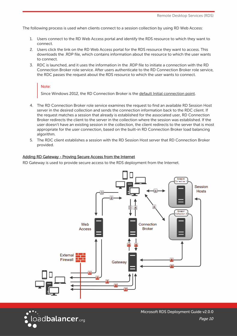
The following process is used when clients connect to a session collection by using RD Web Access:
1. Users connect to the RD Web Access portal and identify the RDS resource to which they want to connect.
2. Users click the link on the RD Web Access portal for the RDS resource they want to access. This downloads the .RDP file, which contains information about the resource to which the user wants to connect.
3. RDC is launched, and it uses the information in the .RDP file to initiate a connection with the RD Connection Broker role service. After users authenticate to the RD Connection Broker role service,the RDC passes the request about the RDS resource to which the user wants to connect.
Note:
Since Windows 2012, the RD Connection Broker is the default Initial connection point.
4. The RD Connection Broker role service examines the request to find an available RD Session Host server in the desired collection and sends the connection information back to the RDC client. If the request matches a session that already is established for the associated user, RD Connection Broker redirects the client to the server in the collection where the session was established. If the user doesn’t have an existing session in the collection, the client redirects to the server that is mostappropriate for the user connection, based on the built-in RD Connection Broker load balancing algorithm.
5. The RDC client establishes a session with the RD Session Host server that RD Connection Broker provided.
Adding RD Gateway - Proving Secure Access from the Internet
RD Gateway is used to provide secure access to the RDS deployment from the Internet.
Microsoft RDS Deployment Guide v2.0.0
Page 10

Remote Desktop Services (RDS)
The additional red numbers show the process when external Internet based users connect to the deployment. In this case, the RD Gateway acts a a proxy when accessing the Connection Brokers and the Session Hosts.
RDS CONFIGURATION – DEPLOYMENT PROPERTIES
HIGH AVAILABILITY SETTINGS
The DNS name for the RD Connection Broker cluster is set during initial deployment and is the FQDN that clients use to connect to the deployment. This FQDN is written to the .RDP files created by Web Access. Once configured, it's not possible to change this via the Windows UI, Powershell must be used instead as described here for Windows 2012, and here for Windows 2016.
Note:
When the Loadbalancer.org appliance is deployed, DNS must configured so that this FQDN points at the Virtual Service (VIP) on the load balancer as explained for the various scenarios on pages 33, 39 & 47.
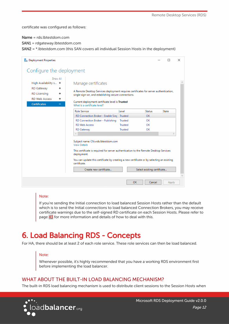
CERTIFICATESFrom Windows 2012, RDS certificates are managed from the Certificates tab of Deployment Properties as shown below. Detailed information about RDS certificate requirements is available here.
Certificate used for this GuideIn the test environment used for this guide, a single certificate signed by an internal CA was used. The
Microsoft RDS Deployment Guide v2.0.0
Page 11
Remote Desktop Services (RDS)
certificate was configured as follows:
Name = rds.lbtestdom.com
SAN1 = rdgateway.lbtestdom.com
SAN2 = *.lbtestdom.com (this SAN covers all individual Session Hosts in the deployment)
Note:
If you're sending the Initial connection to load balanced Session Hosts rather than the default which is to send the Initial connections to load balanced Connection Brokers, you may receive certificate warnings due to the self-signed RD certificate on each Session Hosts. Please refer to page 43 for more information and details of how to deal with this.
6. Load Balancing RDS - ConceptsFor HA, there should be at least 2 of each role service. These role services can then be load balanced.
Note:
Whenever possible, it's highly recommended that you have a working RDS environment first before implementing the load balancer.
WHAT ABOUT THE BUILT-IN LOAD BALANCING MECHANISM?The built-in RDS load balancing mechanism is used to distribute client sessions to the Session Hosts when
Microsoft RDS Deployment Guide v2.0.0
Page 12

Load Balancing RDS - Concepts
the Initial connection is handled by the Connection Brokers (the default Microsoft recommended method).It is not used by any other role service.
WHICH ROLE SERVICES SHOULD I LOAD BALANCE?All role services that are deployed should be load balanced to provide HA:
• Connection Brokers
• Session Hosts
Note:
It is possible to load balance Session Hosts using an external load balancer rather than the built-in RDS load balancing mechanism. In this case, the Initial connection is handled by the load balanced Session Hosts rather than the load balanced Connection Brokers.
All load balancing scenario's are explained in Section 7 starting on page 18.
Note:
It's not possible to load balance Connection Brokers and Session Hosts with an external load balancer at same time. If Connection Brokers are load balanced, clients are send directly or via the load balancer to a specific Session Host - specifying a load balanced FQDN for the Session Hosts is not possible. Likewise, if Session Hosts are load balanced, the Session Hosts refer directly to the Connection Brokers and specifying a load balanced FQDN for the Connection Brokers is not possible.
• Web Access Servers
• Gateways
LOAD BALANCED PORTS & SERVICESThe following table shows the RDS ports and services that are load balanced:
Protocol Port Purpose / Role Service
TCP/HTTPS 443 HTTPS (RD Gateway, RD Web Access)
TCP/UDP/RDP 3389 RDP (UDP transport was added in RDP v8.0)
UDP 3391 RDP (RD Gateway)
PERSISTENCE (SERVER AFFINITY) REQUIREMENTS & OPTIONSPersistence means consistently sending a particular client to the same back-end server during a particular session. This must be enabled for some role services. The following table summarizes the requirements:
Service LB.org AppliancePersistence Required?
Comments LB.org Appliance Persistence Method(s)
Virtualization Hosts
N/A Virtualization Hosts are not load balanced using the LB.org appliance. Connection Broker & the built-in load
N/A
Microsoft RDS Deployment Guide v2.0.0
Page 13

Load Balancing RDS - Concepts
balancing mechanism is used to re-establish client / desktop sessions.
Session Hosts Yes When the Initial connection is handled by load balanced Connection Brokers (the default), Session Host load balancing is handled by the built-in load balancing mechanism.
When the Initial connection is handled by load balanced Session Hosts, and you're happy for redirected sessions to go direct to the Session Hosts (the default).
When the Initial connection is handled by load balanced Session Hosts, and you want to ensure all sessions (both new and redirected) pass via the load balancer.
For a minimal deployment without Connection Broker with just the load balancer & 2 or more Session Hosts.
N/A
Source IP - this is required to ensure that both TCP & UDP traffic for the RDP session is handled by the same Session Host for new connections.
MS Session Broker - for this to work, all Session Hosts must be configured in Routing Token Redirection Mode. In this mode, UDP transport for RDS is not supported because a Layer 7 VIP is required, which does not support UDP.
Source IP
or
RDP Client Cookie
Connection Brokers
No Persistence is not required since the load balancer only handles the Initial connection and not the active RDP session.
N/A
Gateways Yes TCP connections for a session must go to the same Gateway and UDP connections the session must go to thesame Gateway, but TCP and UDP can be handled by different Gateways.
Source IP
Web Access Servers
Yes Uses IIS with authentication which is toa specific server.
Source IP
or
HTTP Cookie
MS SESSION BROKER PERSISTENCEThis mode can only be used when the Initial connection is handled by load balanced Session Hosts. In this mode, the load balancer interacts with Connection Broker by enabling Routing Token Redirection Mode on the Session Hosts. This mode allows the re connection of disconnected sessions by utilizing a Routing Token to enable the load balancer to re–connect the client to the correct Session Host. Routing Token
Microsoft RDS Deployment Guide v2.0.0
Page 14
Load Balancing RDS - Concepts
redirection Mode works as follows:
1. The client connects to the VIP on the load balancer and is load balanced to one of the Session Hosts.
2. The Session Host authenticates the user and checks with one of the Connection Brokers if the userhas an existing, disconnected session.
3. If there is an existing session, the IP address for the Session Host where the session is running is encoded in a Routing Token and returned to the client via the load balancer.
4. The client then reconnects to the load balancer presenting this Routing Token, the load balancer then connects the client to the Session Host specified in the Routing Token.
5. If there was no existing session, a new session is started on the Session Host where the user was originally load balanced.
For more information about redirection modes, please refer to this URL. For more information about Routing Tokens, please refer to page 25-27 of this document.
Note:
If this persistence method is used, all connections will pass via the load balancer, including those that have been redirected.
Since this persistence method requires a layer 7 VIP, UDP is not supported, which means that Session Host connectivity for internal and external clients (via the Gateway) will only utilize TCP.
SOURCE IP PERSISTENCEThis method is appropriate when each clients actual source IP addresses can be seen by the load balancer.This will typically be the case within a LAN but in some situations – e.g. a remote office connecting via some kind of NAT device, all clients would appear to come from the same address and therefore load may not be evenly distributed between the RDS servers.
RDP CLIENT COOKIE PERSISTENCEThis method can be used with a simple deployment which does not have Connection Broker, just Session Hosts and the load balancer appliance. It utilizes the cookie sent from the client in the Connection Request PDU. This cookie is created when the username is entered at the first client login prompt (mstsc.exe). If the username is not entered here, the cookie is not created.
The cookie only supports up to 9 characters, so this method may have limited use, especially in cases where users login using the domain\username format. In this case, if the domain name was 9 characters inlength, the RDP cookie would be the same for all users, resulting in all sessions being sent to the same Session Host. If users login using the UPN format (User Principle Name), i.e. username@domain, it's more likely to be unique.
Note:
When RDP cookie persistence is selected, the load balancer will attempt to use RDP cookie persistence, but if a cookie is not found, source IP persistence will be used instead as a fallback.
LOAD BALANCER DEPLOYMENT MODEThe load balancer can be deployed in 4 fundamental ways: Layer 4 DR mode, Layer 4 NAT mode, Layer 4 SNAT mode and Layer 7 SNAT mode. These modes are explained in detail in the appendix starting on page48.
Web Access ServersLayer 7 SNAT mode is recommended for Web Access servers. If Web Access servers are collocated with
Microsoft RDS Deployment Guide v2.0.0
Page 15

Load Balancing RDS - Concepts
Gateways, Layer 7 SNAT mode must also be used for the Gateway's TCP part. This is because it's not possible to configure a layer 7 SNAT mode VIP and a layer 4 SNAT mode VIP with the same real servers listening on the same port..
Connection BrokersLayer 7 SNAT mode is recommended for Connection Brokers although any other mode can be used if preferred.
Gateways
Layer 4 SNAT mode is recommended for the UDP part of RD Gateway and Layer 7 SNAT mode is recommended for TCP. Layer 4 SNAT mode can also be used for the TCP part, but when RD Gateway and Web Access are collocated, you'd also need to use layer 4 SNAT for Web Access for the reason mentioned in the Web Access servers section above.
Session HostsIf you're load balancing Session Hosts and you require all sessions (both new and redirected) to pass via the load balancer, you must use Layer 7 SNAT mode with MS Session Broker persistence and you must enable Routing Token Redirection Mode on each Session Host. The downside here is that RDP over UDP will not work for internal clients and the external clients who pass via the Gateway. This is because layer 7 SNAT mode does not support UDP.
If you require UDP support for internal and external clients, one of the layer 4 methods must be used. Layer 4 SNAT mode is recommended since no real server changes are required.
If Layer 4 methods are used, it will not be possible to use Routing Token Redirection Mode. The default method (IP Address Redirection Mode) must be used.
If you use NAT mode, the default gateway of the Session Hosts must be the load balancer.
If you use DR mode you'll need to solve the 'ARP problem' as explained in the Administration Manual. You'll also need to configure the following registry entry on each Session Host to ensure that the main interface IP address and not the loopback adapter address is passed back to the client for re-connection:
HKLM\SYSTEM\CurrentControlSet\Control\Terminal Server\ClusterSettings
SessionDirectoryRedirectionIP - set to the IP address to send to the client, this should be the main interface IP address of the Session Host
DEPLOYING THE LOAD BALANCER – VIP LOCATIONThe following VIPs are normally configured on the load balancer when load balancing Remote Desktop Services:
• VIP1 – the connection point for the load balanced Web Access Servers
• VIP2 – the connection point for the load balanced Connection Brokers. DNS should be configuredso that the DNS Name for the RD Connection Broker Cluster specified in the Deployment Properties of the RDS deployment resolves to this VIP
• VIP3 - the connection point for the load balanced RD Gateway Servers
Microsoft RDS Deployment Guide v2.0.0
Page 16

Load Balancing RDS - Concepts
When using the default Microsoft recommended deployment, Session Hosts are load balanced by the builtin mechanism as described earlier on page 9 so there is no VIP for the Session Hosts.
The following diagram illustrates where the load balancer is deployed when the Standard Microsoft deployment is used:
Notes
• The Initial connection is from RDP client to Connection Broker as recommended by Microsoft
• The Loadbalancer.org server feedback agent cannot be used in this case because the Session Hosts are load balanced by the built-in load balancing mechanism and not by the Loadbalancer.org appliance.
If you want to use the Loadbalancer.org feedback agent, you'll need to send the Initial connection to the load balanced Session Hosts rather than the load balanced Connection Brokers as described in load balancing Scenario 5 on page 23.
• A Session Collection is simply a way to group Session Hosts for load balancing, RemoteApp publishing, and common settings purposes. For example, if you set the Idle session limit to 3 hoursin the properties of the collection, then all Session Hosts that are part of the collection will have a 3 hour idle timeout.
Note:
If you're looking to use the appliance to load balance Session Hosts please refer to page 23.
Microsoft RDS Deployment Guide v2.0.0
Page 17

Remote Desktop Services – Load Balancing Scenarios
7. Remote Desktop Services – Load Balancing Scenarios
SCENARIO 1 - LOAD BALANCING WEB ACCESS SERVERSScenario 1 is part of the Standard Deployment as illustrated on page 17.
Client Connection Process:
1. Client initiates session request to the VIP on the load balancer
2. The load balancer forwards the request to one of the load balanced Web Access servers
3. The client continues the session to the selected Web Access server via the load balancer (assuming a layer 7 SNAT configuration as used in this guide)
Scenario Notes:
• Web Access servers use IIS so it's effectively the same as load balancing Microsoft Web Servers.
• Session persistence from client to Web Access server is based on client source IP address.
• The Web Access servers have a built in HTTP --> HTTPS redirect, so the VIP also listens on port 80 to enable this to function correctly.
• Layer 7 SNAT mode is recommended and is used for the example in this guide. It's also possible to use Layer 4 DR, NAT or SNAT modes depending on your infrastructure and requirements (see pages 48 , 49 & 50 for descriptions of these modes).
• Clients connect using a Web Browser.
Note:
See page 29 for load balancer configuration steps and RDS configuration notes related to this scenario.
Microsoft RDS Deployment Guide v2.0.0
Page 18

Remote Desktop Services – Load Balancing Scenarios
SCENARIO 2A - LOAD BALANCING CONNECTION BROKERS WITH SESSION HOSTSScenario 2 is part of the Standard Deployment as illustrated on page 17.
Client Connection Process:
1. Client initiates session request to the VIP on the load balancer
2. The load balancer forwards the request to one of the load balanced Connection Brokers
3. The Connection Broker checks the SQL database to determine if the user has an existing session, ifyes the IP address for that server is selected, if no then the RDS built in load balancing mechanism selects a host/IP address where to start a new session
4. The Connection Broker returns this IP address back to the client via the load balancer (assuming a Layer 7 configuration as used in this guide)
5. The client connects directly to the Session Host specified
Scenario Notes:
• In this scenario the Initial connection is to the Connection Brokers (via the load balancer).
• Session persistence from client to Connection Broker is not required because it handles the initial request and not active sessions.
• Layer 7 SNAT mode is recommended and is used for the example in this guide. It's also possible to use Layer 4 DR, NAT or SNAT modes depending on your infrastructure and requirements (see pages 48 , 49 & 50 for descriptions of these modes).
• Clients connect using RemoteAPP via RD Web Access or modified .RDP files and not just by specifying the DNS name or IP address of the Connection Brokers in mstsc.exe as explained here.
Note:
See page 30 for load balancer configuration steps and RDS configuration notes related to this scenario.
Microsoft RDS Deployment Guide v2.0.0
Page 19

Remote Desktop Services – Load Balancing Scenarios
SCENARIO 2B - LOAD BALANCING CONNECTION BROKERS WITH VIRTUALIZATION HOSTSScenario 2 is part of the Standard Deployment as illustrated on page 17.
Client Connection Process:
1. Client initiates session request to the VIP on the load balancer
2. The load balancer forwards the request to one of the load balanced Connection Brokers
3. The Connection Broker checks the SQL database to determine if the user has an existing session, ifyes the IP address for that server is selected, if no then the RDS built in load balancing mechanism selects a host/IP address where to start a new session
4. The Connection Broker returns this IP address back to the client via the load balancer (assuming a Layer 7 configuration as used in this guide)
5. The client connects directly to the virtualization host specified
Scenario Notes:
• In this scenario the Initial connection is to the Connection Brokers (via the load balancer).
• Session persistence from client to Connection Broker is not required because it handles the initial request and not active sessions.
• Layer 7 SNAT mode is recommended and is used for the example in this guide. It's also possible to use Layer 4 DR, NAT or SNAT modes depending on your infrastructure and requirements (see pages 48 , 49 & 50 for descriptions of these modes).
• Clients connect using RemoteAPP via RD Web Access or modified .RDP files and not just by specifying the DNS name or IP address of the Connection Brokers in mstsc.exe as explained here.
Note:
See page 30 for load balancer configuration steps and RDS configuration notes related to this scenario.
Microsoft RDS Deployment Guide v2.0.0
Page 20
Remote Desktop Services – Load Balancing Scenarios
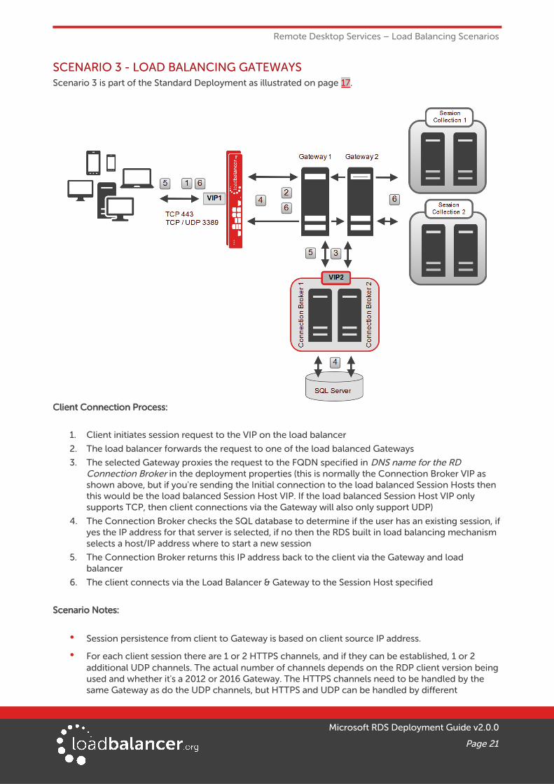
SCENARIO 3 - LOAD BALANCING GATEWAYSScenario 3 is part of the Standard Deployment as illustrated on page 17.
Client Connection Process:
1. Client initiates session request to the VIP on the load balancer
2. The load balancer forwards the request to one of the load balanced Gateways
3. The selected Gateway proxies the request to the FQDN specified in DNS name for the RD Connection Broker in the deployment properties (this is normally the Connection Broker VIP as shown above, but if you're sending the Initial connection to the load balanced Session Hosts then this would be the load balanced Session Host VIP. If the load balanced Session Host VIP only supports TCP, then client connections via the Gateway will also only support UDP)
4. The Connection Broker checks the SQL database to determine if the user has an existing session, ifyes the IP address for that server is selected, if no then the RDS built in load balancing mechanism selects a host/IP address where to start a new session
5. The Connection Broker returns this IP address back to the client via the Gateway and load balancer
6. The client connects via the Load Balancer & Gateway to the Session Host specified
Scenario Notes:
• Session persistence from client to Gateway is based on client source IP address.
• For each client session there are 1 or 2 HTTPS channels, and if they can be established, 1 or 2 additional UDP channels. The actual number of channels depends on the RDP client version being used and whether it's a 2012 or 2016 Gateway. The HTTPS channels need to be handled by the same Gateway as do the UDP channels, but HTTPS and UDP can be handled by different
Microsoft RDS Deployment Guide v2.0.0
Page 21

Remote Desktop Services – Load Balancing Scenarios
Gateways. For more information please refer to this link.
Note:
If the Gateways proxy the RDP connections to load balanced Session Hosts, rather than the default which is to proxy RDP connections to load balanced Connection Servers, you must use a single VIP for the load balanced Gateways. This is required to ensure that both TCP and UDP are handled by the same RD Gateway. Then, when the VIP for the Session Hosts handles the connections, the source IP address is the same for both TCP & UDP and therefore both are forwarded to the same Session Host. If different VIPs were used for TCP and UDP then it's possible that the UDP and TCP for the same session would be forwarded to different Session Hosts which would not work. The VIP configuration in this case is covered page 38.
• Layer 7 SNAT mode is recommended for the TCP part and layer 4 SNAT mode is recommended forthe UDP part , and are used for the example in this guide. It's also possible to use Layer 4 DR mode or layer 4 NAT mode depending on your infrastructure and requirements (see pages 48 , 49 for descriptions of these modes).
• Clients connect using RemoteAPP via RD Web Access, modified .RDP files or via mstsc.exe.
Note:
See page 34 for load balancer configuration steps and RDS configuration notes related to this scenario.
SCENARIO 4 - LOAD BALANCING STAND ALONE SESSION HOSTSScenario 4 is NOT part of the Standard Deployment illustrated on page 17. It offers a simple alternative to afull RDS deployment utilizing just Session Hosts and the load balancer.
Client Connection Process:
1. Client initiates session request to the VIP on the load balancer
2. If the client has connected previously, and the persistence (stick) table entry has not timed out, theload balancer forwards the request to the same Session Host that was used for the previous session, if the client has not connected previously or the stick-table entry has expired, the request is load balanced to one of the Session Hosts according to the load balancing algorithm selected
3. The client continues the session to the selected Session Host via the load balancer (assuming a Layer 7 configuration as used in this guide)
Scenario Notes:
• Appropriate for simple deployments that only require multiple full desktop sessions.
Microsoft RDS Deployment Guide v2.0.0
Page 22

Remote Desktop Services – Load Balancing Scenarios
• In this scenario Connection Broker is not used.
• RemoteApp programs and Web Access are not available or supported.
• In this scenario, session persistence can be based on client source IP address or the RDP cookie (mstshash – see page 15 for more details) sent from the client in the Connection Request PDU.
• For Windows 2012 / 2016 It will not be possible to use Server Manager and/or most of the RDS Powershell commands to manage RDS. You will need to use group policy settings, WMI & registry edits.
• Layer 7 SNAT mode is recommended and is used for the example in this guide. It's also possible to use Layer 4 DR, NAT or SNAT mode depending on your infrastructure and requirements (see pages 48 , 49 & 50 for descriptions of these modes).
• Clients connect using the Microsoft RDP client (mstsc.exe) or equivalent.
Note:
For more details on using Session Host without Connection Broker, please refer to this URL.
Note:
See page 39 for load balancer configuration steps and RDS configuration notes related to this scenario.
SCENARIO 5 - LOAD BALANCING SESSION HOSTS WHEN DEPLOYED WITH CONNECTION BROKERScenario 5 is NOT part of the Standard Deployment illustrated on page 17. Here, the Session Hosts are loadbalanced by the load balancer appliance rather than the built-in mechanism of RDS.
Microsoft RDS Deployment Guide v2.0.0
Page 23

Remote Desktop Services – Load Balancing Scenarios
Client Connection Process:
For IP Address Redirection Mode (the default)
1. Client initiates session request to the VIP on the load balancer
2. The load balancer forwards the request to one of the load balanced Session Hosts
3. The Session Host checks with one of the active/active Connection Brokers to determine if there is an existing session
4. If there is an existing session, the IP address for the Session Host where the session is running is passed to the client in the encrypted load balance packet
5. -
6. The client then reconnects directly to the Session Host specified
If there was no existing session, a new session is started on the Session Host where the user was originally load balanced
For Routing Token Redirection Mode (configured via Group Policy)
1. Client initiates session request to the VIP on the load balancer
2. The load balancer forwards the request to one of the load balanced Session Hosts
3. The Session Host checks with one of the active/active Connection Broker to determine if there is an existing session
4. If there is an existing session, the IP address for the Session Host where the session is running is encoded in a Routing Token and returned to the client via the load balancer
5. The client then reconnects to the load balancer presenting this Routing Token, the load balancer then connects the client to the Session Host specified in the Routing Token
If there was no existing session, a new session is started on the Session Host where the user was originally load balanced
Note:
For detailed information about Routing Tokens and their format please refer to this document.
Scenario Notes:
• In this scenario the Initial connection is handled by the load balanced Session Hosts, this is not the default Microsoft method. For Windows 2012 and later, the default is to send the Initial connectionto the load balanced Connection Brokers as per Scenarios 2a & 2b on pages 19 & 20.
• The built in load balancing mechanism must be disabled for all Session Hosts so that only the LB.org appliance is responsible for load balancing connections to the Session Hosts. This is achieved through Group Policy as described on page 42.
• In this scenario the Loadbalancer.org feedback agent can be used to modify the load balancing algorithm in real time based on Session Host RAM & CPU utilization.
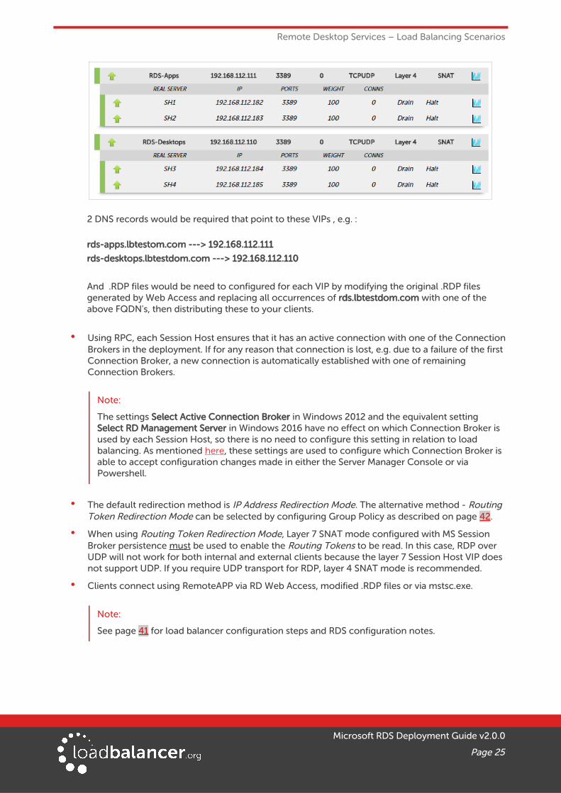
• The load balancer is not aware of RDS Session Collections, so if the deployment consists of more than one Collection, multiple VIPs are needed segregating the Session Hosts according to Session Collection membership. Also, Web Access no longer works correctly and .RDP files need to be manually modified/created to ensure clients are sent to the correct VIP.
For Example, if you have 2 Session Collections each with 2 Session Hosts, you would need to create 2 VIPs as shown below:
Microsoft RDS Deployment Guide v2.0.0
Page 24
Remote Desktop Services – Load Balancing Scenarios
2 DNS records would be required that point to these VIPs , e.g. :
rds-apps.lbtestom.com ---> 192.168.112.111
rds-desktops.lbtestdom.com ---> 192.168.112.110
And .RDP files would be need to configured for each VIP by modifying the original .RDP files generated by Web Access and replacing all occurrences of rds.lbtestdom.com with one of the above FQDN's, then distributing these to your clients.
• Using RPC, each Session Host ensures that it has an active connection with one of the ConnectionBrokers in the deployment. If for any reason that connection is lost, e.g. due to a failure of the first Connection Broker, a new connection is automatically established with one of remaining Connection Brokers.
Note:
The settings Select Active Connection Broker in Windows 2012 and the equivalent setting Select RD Management Server in Windows 2016 have no effect on which Connection Broker is used by each Session Host, so there is no need to configure this setting in relation to load balancing. As mentioned here, these settings are used to configure which Connection Broker is able to accept configuration changes made in either the Server Manager Console or via Powershell.
• The default redirection method is IP Address Redirection Mode. The alternative method - Routing Token Redirection Mode can be selected by configuring Group Policy as described on page 42.
• When using Routing Token Redirection Mode, Layer 7 SNAT mode configured with MS Session Broker persistence must be used to enable the Routing Tokens to be read. In this case, RDP over UDP will not work for both internal and external clients because the layer 7 Session Host VIP does not support UDP. If you require UDP transport for RDP, layer 4 SNAT mode is recommended.
• Clients connect using RemoteAPP via RD Web Access, modified .RDP files or via mstsc.exe.
Note:
See page 41 for load balancer configuration steps and RDS configuration notes.
Microsoft RDS Deployment Guide v2.0.0
Page 25

Loadbalancer.org Appliance – the Basics
8. Loadbalancer.org Appliance – the Basics
VIRTUAL APPLIANCE DOWNLOAD & DEPLOYMENTA fully featured, fully supported 30 day trial is available if you are conducting a PoC (Proof of Concept) deployment. The VA is currently available for VMware, Virtual Box, Hyper-V, KVM and XEN and has been optimized for each Hypervisor. By default, the VA is allocated 1 CPU, 2GB of RAM and has an 8GB virtual disk. The Virtual Appliance can be downloaded here.
Note:
The same download is used for the licensed product, the only difference is that a license key file(supplied by our sales team when the product is purchased) must be applied using the appliance's WebUI.
Note:
Please refer to the Administration Manual and the ReadMe.txt text file included in the VA download for more detailed information on deploying the VA using various Hypervisors.
INITIAL NETWORK CONFIGURATIONThe IP address, subnet mask, default gateway and DNS settings can be configured in several ways as detailed below:
Method 1 - Using the Network Setup Wizard at the console
After boot up, follow the instructions on the console to configure the IP address, subnet mask, default gateway and DNS settings.
Method 2 - Using the WebUI
Using a browser, connect to the WebUI on the default IP address/port: http://192.168.2.21:9080
To set the IP address & subnet mask, use: Local Configuration > Network Interface Configuration
To set the default gateway, use: Local Configuration > Routing
To configure DNS settings, use: Local Configuration > Hostname & DNS
Method 3 - Using Linux commands
At the console, set the initial IP address using the following command:
ip addr add <IP address>/<mask> dev eth0
At the console, set the initial default gateway using the following command:
route add default gw <IP address> <interface>
At the console, set the DNS server using the following command:
echo nameserver <IP address> >> /etc/resolv.conf
Note:
If method 3 is used, you must also configure these settings using the WebUI, otherwise the settings will be lost after a reboot
Microsoft RDS Deployment Guide v2.0.0
Page 26

Loadbalancer.org Appliance – the Basics
ACCESSING THE WEB USER INTERFACE (WEBUI)
The WebUI can be accessed via HTTP at the following URL: http://192.168.2.21:9080/lbadmin
* Note the port number → 9080
The WebUI can be accessed via HTTPS at the following URL: https://192.168.2.21:9443/lbadmin
* Note the port number → 9443
(replace 192.168.2.21 with the IP address of your load balancer if it's been changed from the default)
Login using the following credentials:
Username: loadbalancer
Password: loadbalancer
Note:
To change the password , use the WebUI menu option: Maintenance > Passwords.
Once logged in, the WebUI will be displayed as shown on the following page:
Microsoft RDS Deployment Guide v2.0.0
Page 27

Loadbalancer.org Appliance – the Basics
HA CLUSTERED PAIR CONFIGURATIONLoadbalancer.org recommend that load balancer appliances are deployed in pairs for high availability. In this guide a single unit is deployed first, adding a secondary slave unit is covered in section 5 of the Appendix on page 55.
Microsoft RDS Deployment Guide v2.0.0
Page 28

Load Balancing Web Access Servers (Scenario 1)
9. Load Balancing Web Access Servers (Scenario 1)Scenario 1 is part of the Standard Deployment as illustrated on page 17. Please also refer to page 18 for detailed notes on how the load balancer interacts with RDS in this scenario.
RDS INSTALLATION & CONFIGURATION
• Use the Remote Desktop Services installation type to perform a Standard deployment with 1 Connection Broker, 1 Web Access Server and the required number of Session Hosts / VirtualizationHosts.
• Add 1 or more Web Access Servers to the deployment.
• Configure RDS Certificates as mentioned on page 11.
APPLIANCE CONFIGURATION
SETTING UP THE VIRTUAL SERVICE (VIP)
1. Using the WebUI, navigate to: Cluster Configuration > Layer 7 – Virtual Services and click Add a New Virtual Service
2. Enter the following details:
3. Enter an appropriate name (Label) for the Virtual Service, e.g. RDS-Web
4. Set the Virtual Service IP address field to the required IP address, e.g. 192.168.112.100
5. Set the Virtual Service Ports field to 80,443
6. Set the Protocol to TCP Mode
7. Click Update
8. Now click Modify next to the newly created Virtual Service
9. Set the Persistence Timeout to 2h (i.e. 2 hours)
10. Configure the Health Check settings to look for an HTTP 200 OK response:
• Set Check Type to Negotiate HTTPS
• Set Check Port to 443
• Leave both Request to Send and Response Expected blank
11. Enable (check) the Timeout checkbox and set both Client Timeout & Real Server Timeout to 2h (i.e.
Microsoft RDS Deployment Guide v2.0.0
Page 29

Load Balancing Web Access Servers (Scenario 1)
2 hours)
12. Click Update
SETTING UP THE REAL SERVERS (RIPS)
1. Using the WebUI, navigate to: Cluster Configuration > Layer 7 – Real Servers and click Add a New Real Server next to the newly created Virtual Service
2. Enter the following details:
3. Enter an appropriate name (Label) for the first Web Access, e.g. Web1
4. Change the Real Server IP Address field to the required IP address, e.g. 192.168.112.180
5. Leave the Real Server Port field blank
6. Click Update
7. Now repeat for your remaining Web Access server(s)
TESTING & VERIFICATIONConfigure DNS so that the FQDN to be used for Web Access resolves to the VIP address. The load balanced Web Access servers should now be accessible via the load balancer.
Connect to the Web Access URL using your browser, e.g. :
https://rds.lbtestdom.com/RDweb
10. Load Balancing Connection Brokers (Scenario's 2a & 2b)
Scenario 2 is part of the Standard Deployment as illustrated on page 17. Please also refer to pages 19 & 20 for detailed notes on how the load balancer interacts with RDS in these scenarios.
RDS INSTALLATION & CONFIGURATION
• Use the Remote Desktop Services installation type to perform a Standard deployment with 1 Connection Broker, 1 Web Access Server and the required number of Session Hosts / VirtualizationHosts.
• Configure Connection Broker HA mode:
Microsoft RDS Deployment Guide v2.0.0
Page 30

Load Balancing Connection Brokers (Scenario's 2a & 2b)
◦ The SQL configuration for the LAB used for this guide is shown below:
DRIVER=SQL Server Native Client 11.0; SERVER=WIN2012-TEST.lbtestdom.com; Trusted_Connection=Yes; APP=Remote Desktop Services Connection Broker; DATABASE=RDCB01
◦ The native client can be downloaded here and must be installed on each Connection Broker
• Add 1 or more Connection Brokers to the deployment.
• Configure RDS Certificates as mentioned on page 11.
• Session Host health checking is periodically performed by the Connection Brokers. The health check interval and other related settings can be changed using the following registry path on eachConnection Broker server:
HKLM/SYSTEM/CurrentControlSet/Services/Tssdis /Parameters
The time related settings in (brackets) are in seconds, please refer to this URL for more details
• If you receive the following error: An authentication error has occurred (Code: 0x607).
This can mean that a custom RDS certificate has been installed on the Session Hosts.
As mentioned here, when the Initial connection is handled by the Connection Broker (the default for Windows 2012 & later), the client will authenticate the Connection Broker using a certificate (and/or Kerberos), and then the Broker will authenticate the target Session Host on behalf on the client.
Make sure that the default self-signed RDS certificate is being used on each Session Host.
Microsoft RDS Deployment Guide v2.0.0
Page 31

Load Balancing Connection Brokers (Scenario's 2a & 2b)
Note:
To revert to the default self-signed RDS certificate, please refer to page 44.
• If you receive the following error:
There are no available computers in the pool. Try connecting again, or contact your network administrator.
This means the internal load balancing mechanism has been disabled. For this scenario, this MUST be enabled – use group policy to re-enable this as explained on page 42.
• After adding the additional Connection Brokers, if you see multiple Event 1016's as shown below:
RD Connection Broker service denied the remote procedure call (RPC) from an unauthorized computer 192.168.112.184
Make sure that the RDS Endpoint Servers group on each Connection Broker server includes all Connection Brokers servers in the deployment as mentioned here.
• Ensure there is a valid DNS entry for the HA Connection Broker defined in the deployment settings.e.g. configure a DNS entry for rds.lbtestdom.com pointing to the VIP address.
APPLIANCE CONFIGURATION
SETTING UP THE VIRTUAL SERVICE (VIP)
1. Using the WebUI, navigate to: Cluster Configuration > Layer 7 – Virtual Services and click Add a New Virtual Service
2. Enter the following details:
Microsoft RDS Deployment Guide v2.0.0
Page 32
Load Balancing Connection Brokers (Scenario's 2a & 2b)
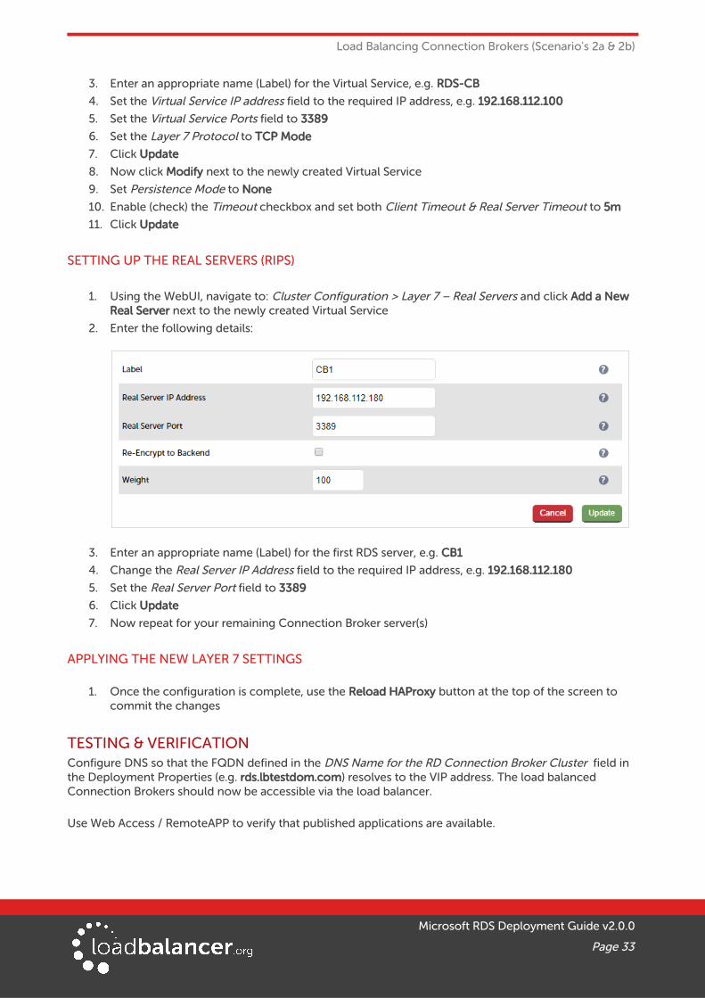
3. Enter an appropriate name (Label) for the Virtual Service, e.g. RDS-CB
4. Set the Virtual Service IP address field to the required IP address, e.g. 192.168.112.100
5. Set the Virtual Service Ports field to 3389
6. Set the Layer 7 Protocol to TCP Mode
7. Click Update
8. Now click Modify next to the newly created Virtual Service
9. Set Persistence Mode to None
10. Enable (check) the Timeout checkbox and set both Client Timeout & Real Server Timeout to 5m
11. Click Update
SETTING UP THE REAL SERVERS (RIPS)
1. Using the WebUI, navigate to: Cluster Configuration > Layer 7 – Real Servers and click Add a New Real Server next to the newly created Virtual Service
2. Enter the following details:
3. Enter an appropriate name (Label) for the first RDS server, e.g. CB1
4. Change the Real Server IP Address field to the required IP address, e.g. 192.168.112.180
5. Set the Real Server Port field to 3389
6. Click Update
7. Now repeat for your remaining Connection Broker server(s)
APPLYING THE NEW LAYER 7 SETTINGS
1. Once the configuration is complete, use the Reload HAProxy button at the top of the screen to commit the changes
TESTING & VERIFICATIONConfigure DNS so that the FQDN defined in the DNS Name for the RD Connection Broker Cluster field in the Deployment Properties (e.g. rds.lbtestdom.com) resolves to the VIP address. The load balanced Connection Brokers should now be accessible via the load balancer.
Use Web Access / RemoteAPP to verify that published applications are available.
Microsoft RDS Deployment Guide v2.0.0
Page 33
Load Balancing Gateways (Scenario 3)
11. Load Balancing Gateways (Scenario 3)Scenario 3 is part of the Standard Deployment as illustrated on page 17. Please also refer to page 21 for detailed notes on how the load balancer interacts with RDS in this scenario.
RDS INSTALLATION & CONFIGURATION
• Use the Remote Desktop Services installation type to perform a Standard deployment with 1 Connection Broker, 1 Web Access Server and the required number of Session Hosts / VirtualizationHosts.
• Add 2 or more Gateways to the deployment.
• Configure RDS Certificates as mentioned on page 11.
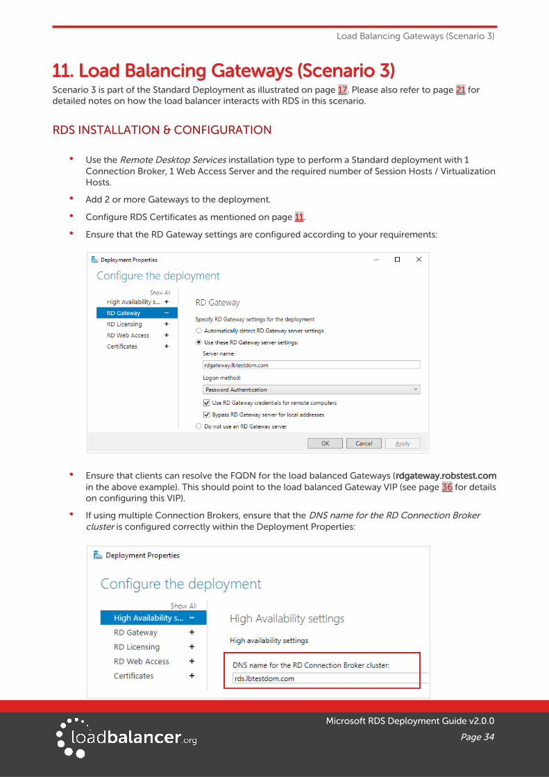
• Ensure that the RD Gateway settings are configured according to your requirements:
• Ensure that clients can resolve the FQDN for the load balanced Gateways (rdgateway.robstest.comin the above example). This should point to the load balanced Gateway VIP (see page 36 for detailson configuring this VIP).
• If using multiple Connection Brokers, ensure that the DNS name for the RD Connection Broker cluster is configured correctly within the Deployment Properties:
Microsoft RDS Deployment Guide v2.0.0
Page 34

Load Balancing Gateways (Scenario 3)
The DNS name (rds.lbtestdom.com in the above example) is used by the RD Gateways to connect to the load balanced Connection Brokers. Create a DNS record with the same name that points to the load balanced Connection Broker VIP and make sure that all RD Gateways can successfully resolve this name.
• Ensure that all load balanced RD Gateways are members of the same RD Gateway server farm as shown in the example below:
• Ensure that the CAP & RAP policies are configured correctly to specify which users can connect to the RDS deployment and which resources they can access. By default all users in the domain are granted access to all computers in the domain.
Also make sure that the FQDN used to access your deployment is included. In Windows 2016 the DNS name for the RD Connection Broker cluster specified in the Deployment Properties is automatically added to the default RAP RDG_HighAvailabilityBroker_DNS_RR.
For additional information about the Resource Authorization Policies in 2016, please refer to this URL.
APPLIANCE CONFIGURATION
• If the Gateways proxy their connections to load balanced Connection Brokers (the default) then two VIPs are used – one for TCP/HTTPS on port 443, the second is for UDP on port 3391. This enables different Gateways to be used for the TCP & UDP parts of the Session. For configuration steps, please refer to the section: Using 2 VIPs – One for TCP, One for UDP below.
• If the Gateways proxy their connections to load balanced Session Hosts, a single VIP must be used to ensure that both TCP and UDP are handled by the same RD Gateway. Then, when the VIP for the Session Hosts handles the connections, the source IP address is the same for both TCP & UDP and therefore both are forwarded to the same Session Host. For configuration steps, please refer to the section: Using a Single Layer 4 SNAT Mode VIP for Both TCP & UDP on page 38.
Note:
If a single layer 4 SNAT mode VIP is used and your deployment has a single Session Collection and RD Gateway is collocated with Web Access, then the Web Access VIP described on page 29must be configured using layer 4 SNAT mode rather than layer 7 SNAT mode.
Microsoft RDS Deployment Guide v2.0.0
Page 35

Load Balancing Gateways (Scenario 3)
USING 2 VIPS – ONE FOR TCP, ONE FOR UDP
Setting up the Virtual Service (VIP) for TCP / HTTPS
1. Using the WebUI, navigate to: Cluster Configuration > Layer 7 – Virtual Services and click Add a New Virtual Service
2. Enter the following details:
3. Enter an appropriate name (Label) for the Virtual Service, e.g. RDS-GW-TCP
4. Set the Virtual Service IP address field to the required IP address, e.g. 192.168.112.102
5. Set the Virtual Service Ports field to 443
6. Set the Layer 7 Protocol to TCP Mode
7. Click Update
8. Now click Modify next to the newly created Virtual Service
9. Enable (check) TCP keep-alive
10. Ensure that Persistence Mode is set to Source IP
11. Leave the Persistence Timeout set to to 30 (i.e. 30 minutes)
12. Enable (check) the Timeout checkbox and set both Client Timeout & Real Server Timeout to 30m (i.e. 30 minutes)
13. Click Update
Setting up the Real Servers (RIPs)
1. Using the WebUI, navigate to: Cluster Configuration > Layer 7 – Real Servers and click Add a New Real Server next to the newly created Virtual Service
2. Enter the following details:
Microsoft RDS Deployment Guide v2.0.0
Page 36
Load Balancing Gateways (Scenario 3)
3. Enter an appropriate name (Label) for the first RD Gateway, e.g. GW1
4. Change the Real Server IP Address field to the required IP address, e.g. 192.168.112.182
5. Set the Real Server Port field to 443
6. Click Update
7. Now repeat for your remaining RD Gateway(s)
Applying the new Layer 7 Settings
1. Once the configuration is complete, use the Reload HAProxy button at the top of the screen to commit the changes
Setting up the Virtual Service (VIP) for UDP
1. Using the WebUI, navigate to: Cluster Configuration > Layer 4 – Virtual Services and click Add a New Virtual Service
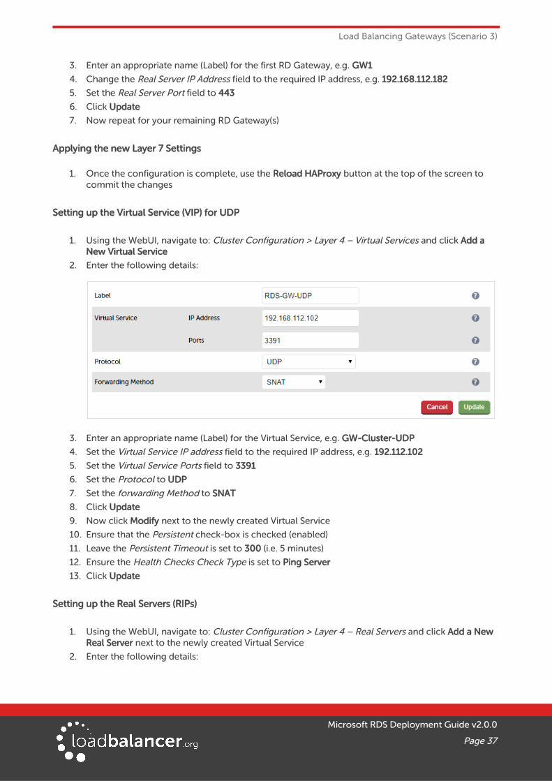
2. Enter the following details:
3. Enter an appropriate name (Label) for the Virtual Service, e.g. GW-Cluster-UDP
4. Set the Virtual Service IP address field to the required IP address, e.g. 192.112.102
5. Set the Virtual Service Ports field to 3391
6. Set the Protocol to UDP
7. Set the forwarding Method to SNAT
8. Click Update
9. Now click Modify next to the newly created Virtual Service
10. Ensure that the Persistent check-box is checked (enabled)
11. Leave the Persistent Timeout is set to 300 (i.e. 5 minutes)
12. Ensure the Health Checks Check Type is set to Ping Server
13. Click Update
Setting up the Real Servers (RIPs)
1. Using the WebUI, navigate to: Cluster Configuration > Layer 4 – Real Servers and click Add a New Real Server next to the newly created Virtual Service
2. Enter the following details:
Microsoft RDS Deployment Guide v2.0.0
Page 37
Load Balancing Gateways (Scenario 3)
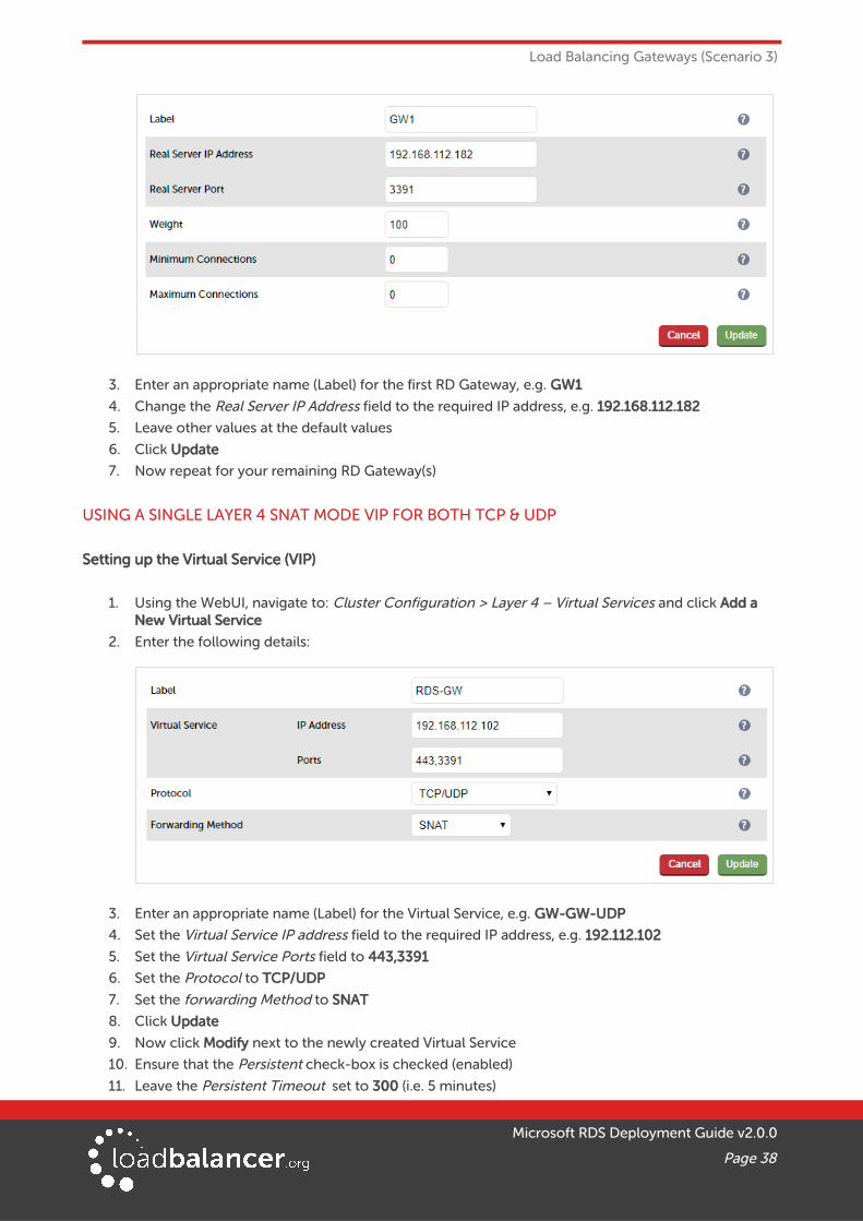
3. Enter an appropriate name (Label) for the first RD Gateway, e.g. GW1
4. Change the Real Server IP Address field to the required IP address, e.g. 192.168.112.182
5. Leave other values at the default values
6. Click Update
7. Now repeat for your remaining RD Gateway(s)
USING A SINGLE LAYER 4 SNAT MODE VIP FOR BOTH TCP & UDP
Setting up the Virtual Service (VIP)
1. Using the WebUI, navigate to: Cluster Configuration > Layer 4 – Virtual Services and click Add a New Virtual Service
2. Enter the following details:
3. Enter an appropriate name (Label) for the Virtual Service, e.g. GW-GW-UDP
4. Set the Virtual Service IP address field to the required IP address, e.g. 192.112.102
5. Set the Virtual Service Ports field to 443,3391
6. Set the Protocol to TCP/UDP
7. Set the forwarding Method to SNAT
8. Click Update
9. Now click Modify next to the newly created Virtual Service
10. Ensure that the Persistent check-box is checked (enabled)
11. Leave the Persistent Timeout set to 300 (i.e. 5 minutes)
Microsoft RDS Deployment Guide v2.0.0
Page 38

Load Balancing Gateways (Scenario 3)
12. Leave the Health Checks Check Type is set to Connect to port
13. Set the Check Port to 443
14. Click Update
Setting up the Real Servers (RIPs)
1. Using the WebUI, navigate to: Cluster Configuration > Layer 4 – Real Servers and click Add a New Real Server next to the newly created Virtual Service
2. Enter the following details:
3. Enter an appropriate name (Label) for the first RD Gateway, e.g. GW1
4. Change the Real Server IP Address field to the required IP address, e.g. 192.168.112.182
5. Leave the Real Server Port field blank
6. Click Update
7. Now repeat for your remaining RD Gateway(s)
TESTING & VERIFICATIONConfigure DNS so the FQDN to be used for RD Gateway (e.g. rdgateway.lbtestdom.com) resolves to the VIP address. Also ensure that the Gateways can resolve the FQDN for the load balanced Connection Brokers (e.g. rds.lbtestdom.com).
Use Web Access / RemoteAPP to verify that published applications are available via the load balancer / Gateways.
12. Load Balancing Standalone Session Hosts (Scenario 4)
Scenario 4 is NOT part of the Standard Deployment illustrated on page 17. It offers a simple alternative to afull RDS deployment utilizing just Session Hosts and the load balancer. Please refer to page 22 for detailed notes on how the load balancer interacts with RDS in this scenario.
RDS INSTALLATION & CONFIGURATION
Microsoft RDS Deployment Guide v2.0.0
Page 39

Load Balancing Standalone Session Hosts (Scenario 4)
• Use the Role-based or feature-based installation type to install the Session Host role service on multiple servers.
• For Windows 2012 / 2016 It will not be possible to use Server Manager and/or most of the RDS Powershell commands to manage RDS. You will need to use group policy settings, WMI & registry edits.
APPLIANCE CONFIGURATION
SETTING UP THE VIRTUAL SERVICE (VIP)
1. Using the WebUI, navigate to: Cluster Configuration > Layer 7 – Virtual Services and click Add a New Virtual Service
2. Enter the following details:
3. Enter an appropriate name (Label) for the Virtual Service, e.g. RDS-SH
4. Set the Virtual Service IP address field to the required IP address, e.g. 192.168.112.100
5. Set the Virtual Service Ports field to 3389
6. Set the Layer 7 Protocol to TCP Mode
7. Click Update
8. Now click Modify next to the newly created Virtual Service
9. Set Persistence Mode to either Source IP or RDP Client Cookie depending on your requirements
Note:
Please refer to page 15 or more details of these persistence methods.
10. Set Persistence Timeout to an appropriate value, e.g. 120 (i.e. 2 hours)
11. Enable (check) the Timeout checkbox and set both Client Timeout & Real Server Timeout to 2h
Note:
If persistence is set to RDP Client Cookie, and the timeout values are left blank, they will be automatically set to 12h. Also, for this persistence mode, TCP Keep-alive is automatically enabled.
Note:
The Persistence Timeout, Client Timeout and Real Server Timeout should be set to the same
Microsoft RDS Deployment Guide v2.0.0
Page 40

Load Balancing Standalone Session Hosts (Scenario 4)
value as the idle session timeout on your Session Hosts.
12. Click Update
SETTING UP THE REAL SERVERS (RIPS)
1. Using the WebUI, navigate to: Cluster Configuration > Layer 7 – Real Servers and click Add a New Real Server next to the newly created Virtual Service
2. Enter the following details:
3. Enter an appropriate name (Label) for the first RDS server, e.g. SH1
4. Change the Real Server IP Address field to the required IP address, e.g. 192.168.112.184
5. Set the Real Server Port field to 3389
6. Click Update
7. Now repeat for your remaining Session Host server(s)
APPLYING THE NEW LAYER 7 SETTINGS
1. Once the configuration is complete, use the Reload HAProxy button at the top of the screen to commit the changes
TESTING & VERIFICATIONConfigure DNS so that the FQDN to be used for your Session Hosts resolves to the VIP address. The load balanced Session Hosts should now be accessible via the load balancer.
Connect to this address from the Microsoft RDP client (mstsc.exe) or equivalent.
13. Load Balancing Session Hosts Deployed with Connection Broker (Scenario 5)
Scenario 5 is NOT part of the Standard Deployment illustrated on page 17. Here, the Session Hosts are loadbalanced by the load balancer appliance rather than the built-in mechanism of RDS. Please refer to page23 for detailed notes on how the load balancer interacts with RDS in this scenario.
RDS INSTALLATION & CONFIGURATION
Microsoft RDS Deployment Guide v2.0.0
Page 41

Load Balancing Session Hosts Deployed with Connection Broker (Scenario 5)
• Use the Remote Desktop Services installation type to perform a Standard deployment with 1 Connection Broker, 1 Web Access Server and the required number of Session Hosts / VirtualizationHosts.
Note:
If your deployment has multiple Session Collections, Web Access will not work correctly as mentioned in the notes for Scenario 5 starting on page 23. However, in these cases it's still useful to install Web Access because it's a useful source for properly-configured .RDP files based on the current configuration of the deployment. This comes in handy when want to manually distribute .RDP files to clients.
• Configure RDS Certificates as mentioned on page 11.
• On all Session Hosts, disable the built in load balancing mechanism:
Using either a Group Policy Object that applies to all Session Hosts or by configuring each server individually using local group policy, disable 'Use RD Connection Broker load balancing'. This settings can be accessed here:
Computer Configuration | Administrative Templates | Windows Components | Remote Desktop Services | Remote Desktop Session Host | RD Connection Broker
• If you want to use Routing Token Redirection Mode, you'll also need to disable IP Address Redirection from the same Group Policy section as shown below:
Note: Make sure that the Session Hosts are already added to the relevant Session Collection beforeconfiguring these settings. If Session Hosts are added to collections afterwards, you may receive the following error:
Unable to configure the RD Session Host sever. Invalid operation.
Microsoft RDS Deployment Guide v2.0.0
Page 42
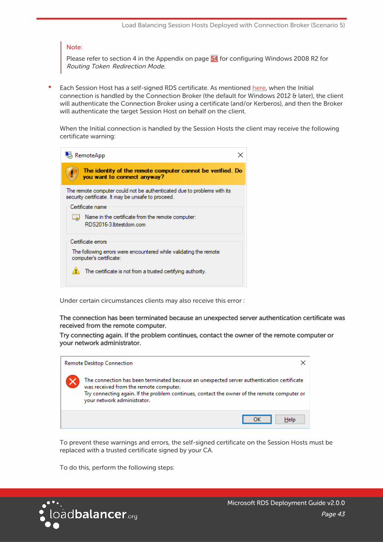
Load Balancing Session Hosts Deployed with Connection Broker (Scenario 5)
Note:
Please refer to section 4 in the Appendix on page 54 for configuring Windows 2008 R2 for Routing Token Redirection Mode.
• Each Session Host has a self-signed RDS certificate. As mentioned here, when the Initial connection is handled by the Connection Broker (the default for Windows 2012 & later), the client will authenticate the Connection Broker using a certificate (and/or Kerberos), and then the Broker will authenticate the target Session Host on behalf on the client.
When the Initial connection is handled by the Session Hosts the client may receive the following certificate warning:
Under certain circumstances clients may also receive this error :
The connection has been terminated because an unexpected server authentication certificate wasreceived from the remote computer.
Try connecting again. If the problem continues, contact the owner of the remote computer or your network administrator.
To prevent these warnings and errors, the self-signed certificate on the Session Hosts must be replaced with a trusted certificate signed by your CA.
To do this, perform the following steps:
Microsoft RDS Deployment Guide v2.0.0
Page 43
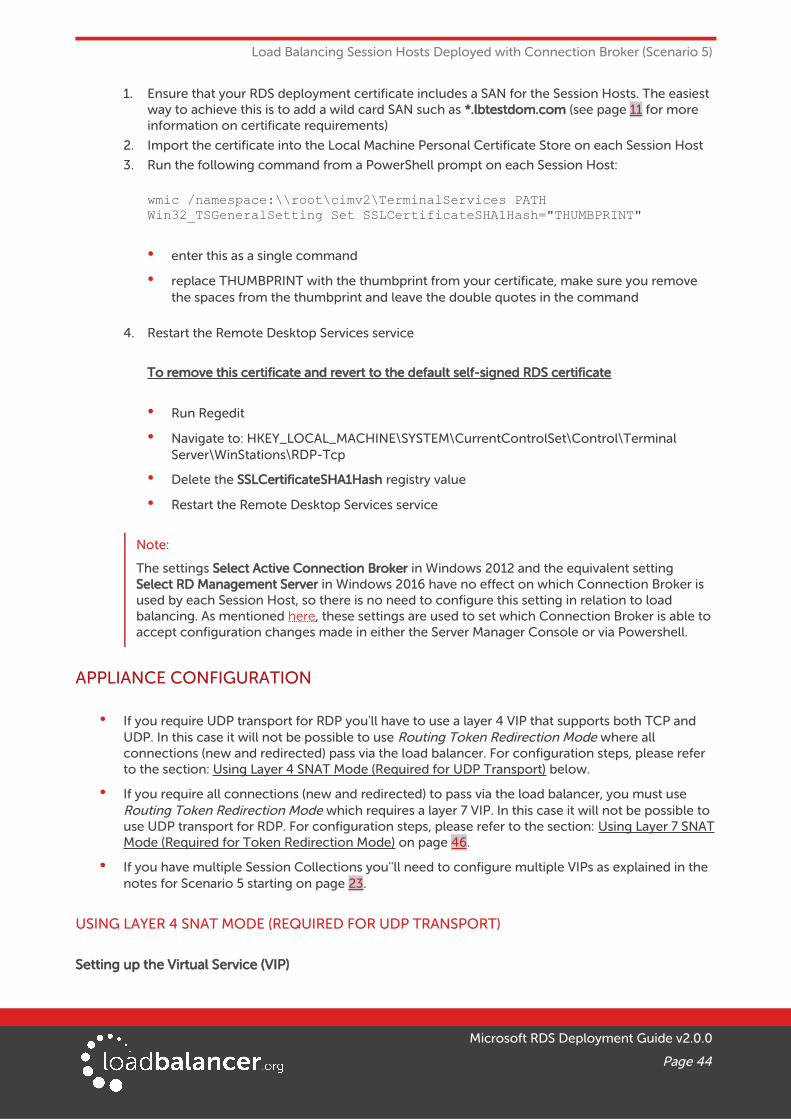
Load Balancing Session Hosts Deployed with Connection Broker (Scenario 5)
1. Ensure that your RDS deployment certificate includes a SAN for the Session Hosts. The easiest way to achieve this is to add a wild card SAN such as *.lbtestdom.com (see page 11 for more information on certificate requirements)
2. Import the certificate into the Local Machine Personal Certificate Store on each Session Host
3. Run the following command from a PowerShell prompt on each Session Host:
wmic /namespace:\\root\cimv2\TerminalServices PATH Win32_TSGeneralSetting Set SSLCertificateSHA1Hash="THUMBPRINT"
• enter this as a single command
• replace THUMBPRINT with the thumbprint from your certificate, make sure you remove the spaces from the thumbprint and leave the double quotes in the command
4. Restart the Remote Desktop Services service
To remove this certificate and revert to the default self-signed RDS certificate
• Run Regedit
• Navigate to: HKEY_LOCAL_MACHINE\SYSTEM\CurrentControlSet\Control\Terminal Server\WinStations\RDP-Tcp
• Delete the SSLCertificateSHA1Hash registry value
• Restart the Remote Desktop Services service
Note:
The settings Select Active Connection Broker in Windows 2012 and the equivalent setting Select RD Management Server in Windows 2016 have no effect on which Connection Broker is used by each Session Host, so there is no need to configure this setting in relation to load balancing. As mentioned here, these settings are used to set which Connection Broker is able toaccept configuration changes made in either the Server Manager Console or via Powershell.
APPLIANCE CONFIGURATION
• If you require UDP transport for RDP you'll have to use a layer 4 VIP that supports both TCP and UDP. In this case it will not be possible to use Routing Token Redirection Mode where all connections (new and redirected) pass via the load balancer. For configuration steps, please refer to the section: Using Layer 4 SNAT Mode (Required for UDP Transport) below.
• If you require all connections (new and redirected) to pass via the load balancer, you must use Routing Token Redirection Mode which requires a layer 7 VIP. In this case it will not be possible to use UDP transport for RDP. For configuration steps, please refer to the section: Using Layer 7 SNATMode (Required for Token Redirection Mode) on page 46.
• If you have multiple Session Collections you''ll need to configure multiple VIPs as explained in the notes for Scenario 5 starting on page 23.
USING LAYER 4 SNAT MODE (REQUIRED FOR UDP TRANSPORT)
Setting up the Virtual Service (VIP)
Microsoft RDS Deployment Guide v2.0.0
Page 44
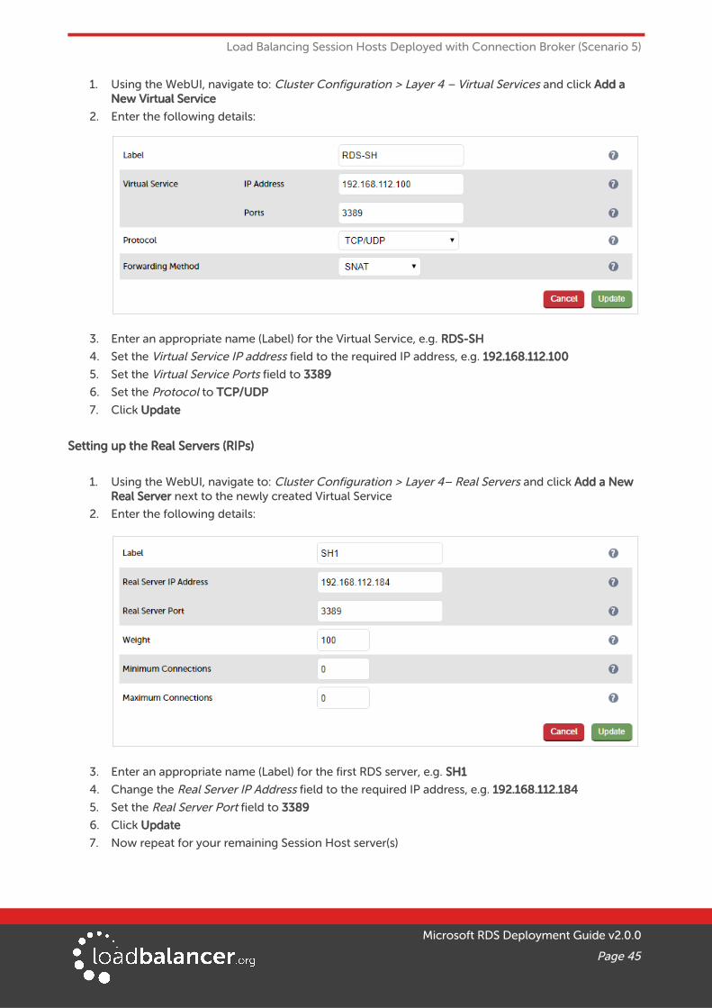
Load Balancing Session Hosts Deployed with Connection Broker (Scenario 5)
1. Using the WebUI, navigate to: Cluster Configuration > Layer 4 – Virtual Services and click Add a New Virtual Service
2. Enter the following details:
3. Enter an appropriate name (Label) for the Virtual Service, e.g. RDS-SH
4. Set the Virtual Service IP address field to the required IP address, e.g. 192.168.112.100
5. Set the Virtual Service Ports field to 3389
6. Set the Protocol to TCP/UDP
7. Click Update
Setting up the Real Servers (RIPs)
1. Using the WebUI, navigate to: Cluster Configuration > Layer 4– Real Servers and click Add a New Real Server next to the newly created Virtual Service
2. Enter the following details:
3. Enter an appropriate name (Label) for the first RDS server, e.g. SH1
4. Change the Real Server IP Address field to the required IP address, e.g. 192.168.112.184
5. Set the Real Server Port field to 3389
6. Click Update
7. Now repeat for your remaining Session Host server(s)
Microsoft RDS Deployment Guide v2.0.0
Page 45

Load Balancing Session Hosts Deployed with Connection Broker (Scenario 5)
USING LAYER 7 SNAT MODE (REQUIRED FOR TOKEN REDIRECTION MODE)
Setting up the Virtual Service (VIP)
1. Using the WebUI, navigate to: Cluster Configuration > Layer 7 – Virtual Services and click Add a New Virtual Service
2. Enter the following details:
3. Enter an appropriate name (Label) for the Virtual Service, e.g. RDS-SH
4. Set the Virtual Service IP address field to the required IP address, e.g. 192.168.112.100
5. Set the Virtual Service Ports field to 3389
6. Set the Layer 7 Protocol to TCP Mode
7. Click Update
8. Now click Modify next to the newly created Virtual Service
9. Set the Persistence Mode to MS Session Broker
Note:
When the Persistence Mode is set to MS Session Broker TCP Keep-alive is automatically enabled.
10. Enable (check) the Timeout checkbox and set both Client & Real Server Timeout to 30m (i.e. 30 minutes)
11. Click Update
Setting up the Real Servers (RIPs)
1. Using the WebUI, navigate to: Cluster Configuration > Layer 7 – Real Servers and click Add a New Real Server next to the newly created Virtual Service
2. Enter the following details:
Microsoft RDS Deployment Guide v2.0.0
Page 46

Load Balancing Session Hosts Deployed with Connection Broker (Scenario 5)
3. Enter an appropriate name (Label) for the first RDS server, e.g. SH1
4. Change the Real Server IP Address field to the required IP address, e.g. 192.168.112.184
5. Set the Real Server Port field to 3389
6. Click Update
7. Now repeat for your remaining Session Host server(s)
Applying the New Layer 7 Settings
1. Once the configuration is complete, use the Reload HAProxy button at the top of the screen to commit the changes
TESTING & VERIFICATIONConfigure DNS so that the FQDN defined in the DNS Name for the RD Connection Broker Cluster field in the Deployment Properties (e.g. rds.lbtestdom.com) resolves to the VIP address. The load balanced Session Hosts should now be accessible via the load balancer.
Connect to this address from Web Access / RemoteAPP if your RDS deployment has a single Session Collection, or via modified .RDP files if there are multiple Session Collections.
14. Technical SupportIf you have any questions regarding the appliance or would like assistance designing your deployment, please don't hesitate to contact our support team: [email protected].
15. Further DocumentationThe Administration Manual contains much more information about configuring and deploying the appliance. It's available here: http://pdfs.loadbalancer.org/loadbalanceradministrationv8.pdf
16. ConclusionLoadbalancer.org appliances provide a very cost effective and flexible solution for highly available load balanced Remote Desktop Services environments.
Microsoft RDS Deployment Guide v2.0.0
Page 47

Appendix
17. Appendix
1 - LOAD BALANCER DEPLOYMENT MODESThe load balancer can be deployed in one of 4 fundamental ways; Layer 4 DR mode, Layer 4 NAT mode, Layer 4 SNAT mode or Layer 7 SNAT mode. These are described below.
LAYER 4 DR MODEOne-arm Direct Routing (DR) mode is a very high performance solution that requires little change to your existing infrastructure.
• DR mode works by changing the destination MAC address of the incoming packet to match the selected Real Server on the fly which is very fast
• When the packet reaches the Real Server it expects the Real Server to own the Virtual Services IP address (VIP). This means that you need to ensure that the Real Server (and the load balanced application) respond to both the Real Servers own IP address and the VIP
• The Real Server should not respond to ARP requests for the VIP. Only the load balancer should dothis. Configuring the Real Servers in this way is referred to as Solving the ARP Problem. Please referto the Administration Manual for more details.
• On average, DR mode is 8 times quicker than NAT for HTTP, 50 times quicker for Terminal Services and much, much faster for streaming media or FTP
• The load balancer must have an Interface in the same subnet as the Real Servers to ensure layer 2 connectivity required for DR mode to work
• The VIP can be brought up on the same subnet as the Real Servers, or on a different subnet provided that the load balancer has an interface in that subnet
• Port translation is not possible in DR mode i.e. having a different RIP port than the VIP port
• DR mode is transparent, i.e. the Real Server will see the source IP address of the client
Microsoft RDS Deployment Guide v2.0.0
Page 48
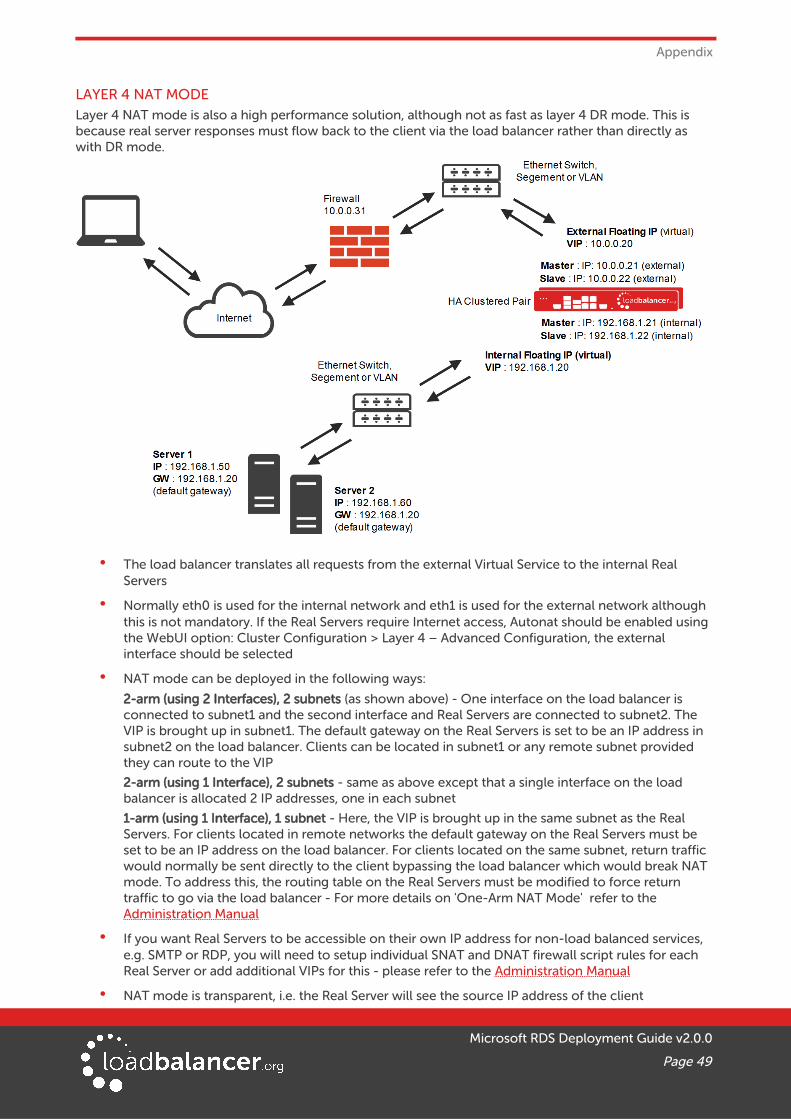
Appendix
LAYER 4 NAT MODELayer 4 NAT mode is also a high performance solution, although not as fast as layer 4 DR mode. This is because real server responses must flow back to the client via the load balancer rather than directly as with DR mode.
• The load balancer translates all requests from the external Virtual Service to the internal Real Servers
• Normally eth0 is used for the internal network and eth1 is used for the external network although this is not mandatory. If the Real Servers require Internet access, Autonat should be enabled using the WebUI option: Cluster Configuration > Layer 4 – Advanced Configuration, the external interface should be selected
• NAT mode can be deployed in the following ways:
2-arm (using 2 Interfaces), 2 subnets (as shown above) - One interface on the load balancer is connected to subnet1 and the second interface and Real Servers are connected to subnet2. The VIP is brought up in subnet1. The default gateway on the Real Servers is set to be an IP address in subnet2 on the load balancer. Clients can be located in subnet1 or any remote subnet provided they can route to the VIP
2-arm (using 1 Interface), 2 subnets - same as above except that a single interface on the load balancer is allocated 2 IP addresses, one in each subnet
1-arm (using 1 Interface), 1 subnet - Here, the VIP is brought up in the same subnet as the Real Servers. For clients located in remote networks the default gateway on the Real Servers must be set to be an IP address on the load balancer. For clients located on the same subnet, return traffic would normally be sent directly to the client bypassing the load balancer which would break NAT mode. To address this, the routing table on the Real Servers must be modified to force return traffic to go via the load balancer - For more details on 'One-Arm NAT Mode' refer to the Administration Manual
• If you want Real Servers to be accessible on their own IP address for non-load balanced services, e.g. SMTP or RDP, you will need to setup individual SNAT and DNAT firewall script rules for each Real Server or add additional VIPs for this - please refer to the Administration Manual
• NAT mode is transparent, i.e. the Real Server will see the source IP address of the client
Microsoft RDS Deployment Guide v2.0.0
Page 49

Appendix
• Port translation is possible in NAT mode, i.e. VIP:80 --> RIP:8080 is possible
LAYER 4 SNAT MODELayer 4 SNAT mode is also a high performance solution, although not as fast as the other layer 4 modes.
• The load balancer translates all requests from the external Virtual Service to the internal Real Servers in the same way as NAT mode (please refer to the previous page for details).
• Layer 4 SNAT mode is not transparent, an iptables SNAT rule translates the source IP address to be the load balancer rather than the original client IP address.
• Layer 4 SNAT mode can be deployed using either a one-arm or two-arm configuration.
• For two-arm deployments, eth0 is normally used for the internal network and eth1 is used for the external network although this is not mandatory. If the Real Servers require Internet access, Autonat should be enabled using the WebUI option: Cluster Configuration > Layer 4 – Advanced Configuration, the external interface should be selected.
• Port translation is not possible in layer 4 SNAT mode i.e. having a different RIP port than the VIP port.
Microsoft RDS Deployment Guide v2.0.0
Page 50

Appendix
LAYER 7 SNAT MODELayer 7 load balancing uses a proxy (HAProxy) at the application layer. Inbound requests are terminated onthe load balancer, and HAProxy generates a new request to the chosen real server. As a result, Layer 7 is a slower technique than DR or NAT mode at Layer 4. Layer 7 is generally chosen when the network topologyprohibits the use of the layer 4 methods.
Single–arm and two–arm configurations are supported as shown below. In both cases return traffic passesvia the load balancer. Since layer 7 works as a proxy, there is not need to set the appliance as the gateway.
This mode can be deployed in a one-arm or two-arm configuration and does not require any changes to the Real Servers. However, since the load balancer is acting as a full proxy it doesn't have the same raw throughput as the layer 4 methods.
The load balancer proxies the application traffic to the servers so that the source of all traffic becomes the load balancer.
• SNAT mode is a full proxy and therefore load balanced Real Servers do not need to be changed in any way
• Because SNAT mode is a full proxy any server in the cluster can be on any accessible subnet including across the Internet or WAN
• SNAT mode is not transparent by default, i.e. the Real Servers will not see the source IP address of the client, they will see the load balancers own IP address by default, or any other local appliance IP address if preferred (e.g. the VIP address), this can be configured per layer 7 VIP
• SNAT mode can be deployed using either a 1-arm or 2-arm configuration
Microsoft RDS Deployment Guide v2.0.0
Page 51

Appendix
3 - SERVER FEEDBACK AGENT
Note:
Utilizing the feedback agent is only relevant when load balancing Session Hosts.
The load balancer can modify the weight (amount of traffic) of each server by gathering data from either a custom agent or an HTTP server. For layer 4 VIPs the feedback method can be set to either agent or HTTP,for Layer 7 VIPs, only the agent method is supported.
A telnet to port 3333 on a Real Server with the agent installed will return the current idle stats as an integervalue in the range 0 – 100. The figure returned can be related to CPU utilization, RAM usage or a combination of both. This can be configured using the XML configuration file located in the agents installation folder (by default C:\ProgramData\LoadBalancer.org\LoadBalancer).
The load balancer typically expects a 0-99 integer response from the agent which by default relates to the current CPU idle state, e.g. a response of 92 would imply that the Real Servers CPU is 92% idle. The load balancer will then use the formula (92/100*requested_weight) to find the new optimized weight. Using this method an idle Real Server will get 10 times as many new connections as an overloaded server.
Note:
The 'Requested Weight' is the weight set in the WebUI for each Real Server added, the default is 100. For more information please also refer to the following blog article:
http://blog.loadbalancer.org/open-source-windows-service-for-reporting-server-load-back-to-haproxy-load-balancer-feedback-agent/
Windows Agent Download
The latest Windows feedback agent can be downloaded from:
http://downloads.loadbalancer.org/agent/loadbalanceragent.msi
To install the agent, run loadbalanceragent.msi on each RDS server.
Click Next
Microsoft RDS Deployment Guide v2.0.0
Page 52

Appendix
Select the installation folder and click Next
Click Next to start the installation
Note:
The agent should be installed on all Real Serves in the cluster.
Starting the Agent
Once the installation has completed, you'll need to start the service on the RDS servers. The service is controlled by the Feedback Agent Monitor program that is also installed along with the Agent. The monitor can be accessed on the Windows server using: All Programs > Loadbalancer.org > Monitor. It's also possible to start the service using the services snap-in – the service is called 'Loadbalancer CPU monitor'.
Microsoft RDS Deployment Guide v2.0.0
Page 53

Appendix
• To start the service, click Start
• To stop the service, click Stop
Configuration
To Configure Virtual Services to use the feedback agent, follow the steps below:
1. Using the WebUI, navigate to: Cluster Configuration > Layer 4 - Virtual Services or Layer 7 - Virtual Services
2. Click Modify next to the Virtual Service
3. Change the Feedback Method to Agent
4. Click Update
5. For layer 7 VIPs, restart HAProxy using the WebUI option: Maintenance > Restart Services
4 - CONFIGURING WINDOWS 2008 R2 FOR ROUTING TOKEN REDIRECTION MODEInstall Connection Broker on the server designated to hold the Connection Broker role. Then on each RDSto be included in the cluster/Farm:
1. Open Remote Desktop Host Session Configuration
2. Right–click 'Member of farm in RD Connection Broker' and select Properties
3. Click Change Settings
4. Select Farm Member, enter the DNS name of the server running the Connection Broker role service and the name of the farm (all servers within the same farm require the same name to be specified) and click OK
5. Leave Participate in Connection Broker Load-Balancing un-checked and select Use token redirection from the drop down as shown below:
Microsoft RDS Deployment Guide v2.0.0
Page 54

Appendix
5 - CLUSTERED PAIR CONFIGURATION – ADDING A SLAVE UNITIf you initially configured just the master unit and now need to add a slave - our recommended procedure,please refer to the relevant section below for more details:
Note:
A number of settings are not replicated as part of the master/slave pairing process and thereforemust be manually configured on the slave appliance. These are listed below:
• Hostname & DNS settings
• Network settings including IP addresses, bonding configuration and VLANs
• Routing configuration including default gateways and static routes
• Date & time settings
• Physical – Advanced Configuration settings including Internet Proxy IP address & port, Firewall table size, SMTP relay and Syslog server
• SNMP settings
• Graphing settings
• Firewall Script & Firewall Lockdown Script settings
• Software updates
Version 7:
Please refer to Chapter 8 – Appliance Clustering for HA in the v7 Administration Manual.
Version 8:
To add a slave node – i.e. create a highly available clustered pair:
• Deploy a second appliance that will be the slave and configure initial network settings
• Using the WebUI, navigate to: Cluster Configuration > High-Availability Configuration
Microsoft RDS Deployment Guide v2.0.0
Page 55

Appendix
• Specify the IP address and the loadbalancer users password (the default is 'loadbalancer') for the slave (peer) appliance as shown above
• Click Add new node
• The pairing process now commences as shown below:
• Once complete, the following will be displayed:
• To finalize the configuration, restart heartbeat and any other services as prompted in the blue message box at the top of the screen
Microsoft RDS Deployment Guide v2.0.0
Page 56

Appendix
Note:
Clicking the Restart Heartbeat button on the master appliance will also automatically restart heartbeat on the slave appliance
Note:
Please refer to chapter 9 – Appliance Clustering for HA in the Administration Manual for more detailed information on configuring HA with 2 appliances.
Microsoft RDS Deployment Guide v2.0.0
Page 57

Appendix
6 - COMPANY CONTACT INFORMATION
Website URL: w w w.loadbalancer.org
North America (US) Loadbalancer.org, Inc.
4250 Lancaster Pike, Suite 120WilmingtonDE 19805USA
Tel:Fax:
Email (sales):Email (support):
+1 888.867.9504+1 [email protected]@loadbalancer.org
North America (Canada) Loadbalancer.org Ltd300-422 Richards StreetVancouver, BCV6B 2Z4Canada
Tel:Fax:
Email (sales):Email (support):
+1 866.998.0508+1 [email protected]@loadbalancer.org
Europe (UK) Loadbalancer.org Ltd.Compass HouseNorth Harbour Business ParkPortsmouth, PO6 4PSUK
Tel:Fax:
Email (sales):Email (support):
+44 (0)330 3801064+44 (0)870 [email protected]@loadbalancer.org
Europe (Germany) Loadbalancer.org GmbHTengstraße 27D-80798MünchenGermany
Tel:Fax:
Email (sales):Email (support):
+49 (0)89 2000 2179+49 (0)30 920 383 [email protected]@loadbalancer.org
Microsoft RDS Deployment Guide v2.0.0
Page 58