local distributor - cotswold valves · contents applications table - g4 series contents page no....
TRANSCRIPT
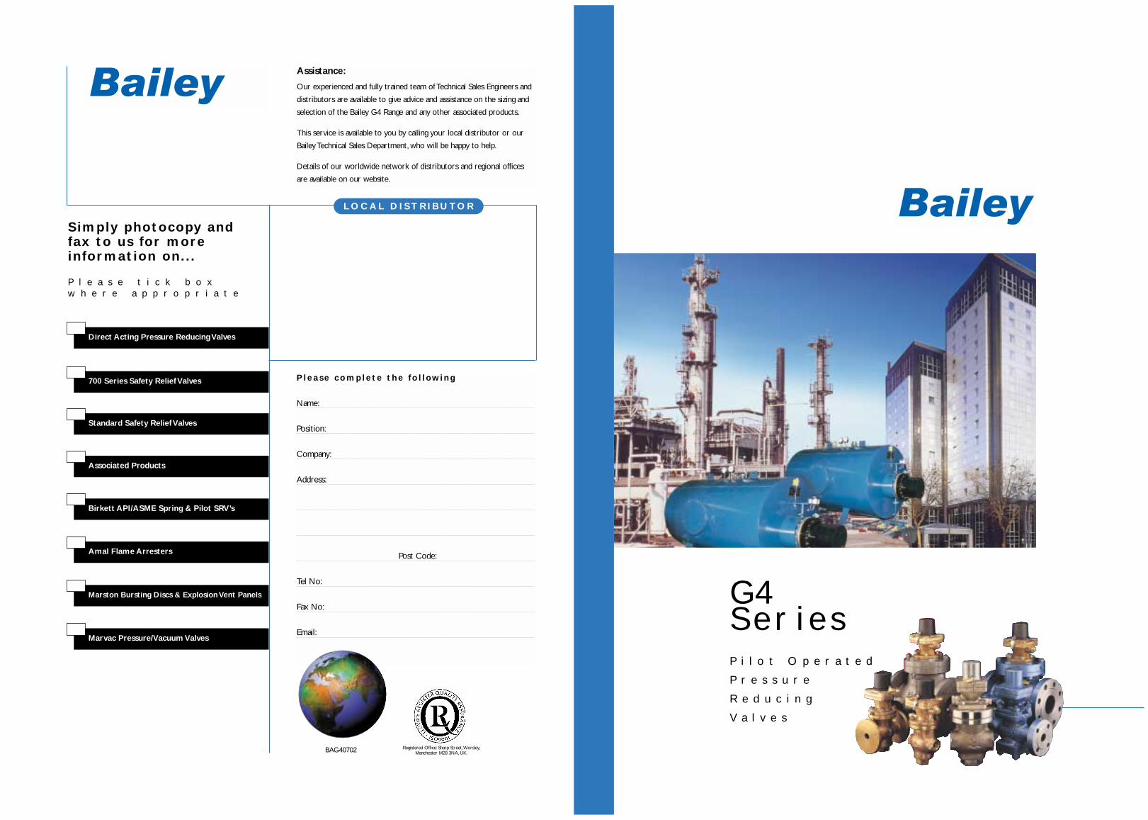
G4SeriesP i l o t O p e r a t e d
P r e s s u r e
R e d u c i n g
V a l v e s
P l e a s e c o m p l e t e t h e f o l l ow i n g
Name:
Position:
Company:
Address:
Post Code:
Tel No:
Fax No:
Email:
Simply photocopy andfax to us for moreinformation on. . .
P l e a s e t i c k b o xw h e r e a p p r o p r i a t e
Associated Products
Standard Safety Relief Valves
700 Series Safety Relief Valves
Direct Acting Pressure Reducing Valves
Marvac Pressure/Vacuum Valves
Marston Bursting Discs & Explosion Vent Panels
Amal Flame Arresters
Birkett API/ASME Spring & Pilot SRV’s
L O C A L D I S T R I B U TO R
Assistance:
Our experienced and fully trained team of Technical Sales Engineers and
distributors are available to give advice and assistance on the sizing and
selection of the Bailey G4 Range and any other associated products.
This service is available to you by calling your local distributor or our
Bailey Technical Sales Department, who will be happy to help.
Details of our worldwide network of distributors and regional offices
are available on our website.
BAG40702 Registered Office: Sharp Street,Worsley,Manchester M28 3NA, UK.

Con
tent
s
APPLICATIONS TABLE - G4 SERIES
C O N T E N T S Page No.
Applications Table 2
Method of Operation 3
Gas and Oxygen Duties 4
Stainless Steel Version 4
Low Pressure Top 4
Sectional Diagram and Parts List 5
Materials 6
Remote Sensing/Balance Pipes 7
Spares Packs 7
Series and Parallel/Installations 8
Installation 9
Setting and Spring Selection 10
Sizing 11 – 12
Surplus and Maintaining Valves 13 – 14
Capacity Charts 15 – 16
Pipe Capacities/Pipe Selection 17 – 18
Technical Specifications 19 – 20
Dimensions 212
APPLICATION MATERIAL SIZE VALVE TYPE
Steam Bronze 15 to 50mm 2042/3Cast Iron 65 to 150mm 2044Cast Steel 65 to 150mm 2045Cast Steel 15 to 150mm 2046
Clean Steam Stainless Steel 15 to 50mm 2042/3 SS
Air and Fine Gas Bronze 15 to 50mm 2042/3 GNCast Iron 65 to 150mm 2044 GPCast Steel 15 to 50mm 2046 GNCast Steel 65 to 150mm 2045/6 GP
Oxygen and Methane Bronze 15 to 50mm 2042/3 OV
Stainless Steel Stainless Steel 15 to 50mm 2042/3 SSEnvironment 2042/3 SN
Accurate selection of G4 valve type depends on: inlet/outletpressure - capacity - material - temperature - fluid -connection required.
• Accuracy, capable of regulating outletpressure within +/-1⁄2%.
• Integral pilot, extremely compact design.
• Self actuated, no external power sourcerequired.
• Fully balanced, stability of control regardlessof inlet pressure fluctuations.
• Full lift capability, maximumcapacity/minimum size.
• Positive shut off, ensures leak free operation.
• Rangeability, wide choice of sizes, materialsand connections.
• Interchangeability, many components areinterchangeable between the various types andsizes, therefore easily adapted, metal/soft seats,high/low pressure.
• World renowned, over 30 years serviceexperience in world wide industries.
• Availability, stocked world-wide by ourcomprehensive distributor network.
• PED, all valves are in full compliance with thePED.
F E AT U R E S A N D B E N E F I T S
RECOMMENDEDG4 SeriesP i l o t O p e r a t e d P r e s s u r e R e d u c i n g V a l v e s
The Bailey ‘G4’ Series of pilot operated
pressure reducing valves offers a
comprehensive range for control of vital
services such as steam, air and fine industrial
gases.The ‘G4’ is a self acting, integral
mounted pilot operated pressure reducing
valve, which is designed to be extremely
compact and versatile.
The ‘G4’ has become a symbol for accuracy
of control, high performance, quality and
reliability. The ‘G4’ has set the standard
which all other pressure reducing valves
strive to achieve.
Bailey can help to specify the most
appropriate size and type of valve for any
specific application.
G4 SeriesT h e c o m p l e t e s o l u t i o nw i t h g l o b a l s u p p o r t
THE LOGICAL CHOICE
Experience, and focus on customer service,
make Bailey the logical choice of supplier for
pressure reducing and regulating valves, to
accurately and continuously control pressures
right around the clock and right around the
world.
A policy of continuous improvement ensures
that Bailey valves will always provide
exceptional reliability and performance.
By choosing Bailey pressure reducing valves, you
are selecting availability, quality, professional
advice and proven performance - all delivered
through an extensive worldwide network of
distributors. Should a valve change-out be
required at short notice, ex-stock availability of
most standard valves ensures minimal plant
downtime and maximum production.
1
Acc
esso
ries
4
GAS AND OXYGEN DUTIES
S TA I N L E S S S T E E L
L OW P R E S S U R E TO P
The ‘G4’ has successfully been used for many yearswith metal seats on demanding steam applications.However soft seated versions are available forindustrial fine gas applications, involving such gasesas carbon dioxide, nitrogen and oxygen.Typicalapplication areas would include pharmaceuticals,food processing and brewing.
The ‘G4’ utilises a range of soft elastomer seatmaterials to meet the ever growing demand forthese specialist applications.
In addition, valves for active gases, such as oxygenand methane, can be supplied fully assembled andtested to “oxygen service” standard in Bailey’s stateof the art clean room facility.This facility compliesfully with the “Industrial Gas Committee”guidelines.
All soft seat options can also be supplied asconversion kits, allowing existing valves and stockto be modified quickly should the need suddenlyarise.
The ‘G4’ is available in a fully stainless steel version,sizes 15 to 50mm, both screwed and flanged.
Hygienic Environments
Changing regulations in the food, drink andpharmaceutical industries around the world, nowoften require all stainless steel pipe work systemsto be used in hygienic environments, which in turnrequire the use of stainless steel pressure reducingvalves.
Clean Steam Applications
Regulations for hospitals, pharmaceutical, food anddrink companies also require clean steam to beused for sterilisation and decontaminationprocesses. Clean steam is very corrosive andrequires stainless steel pressure reducing valves.
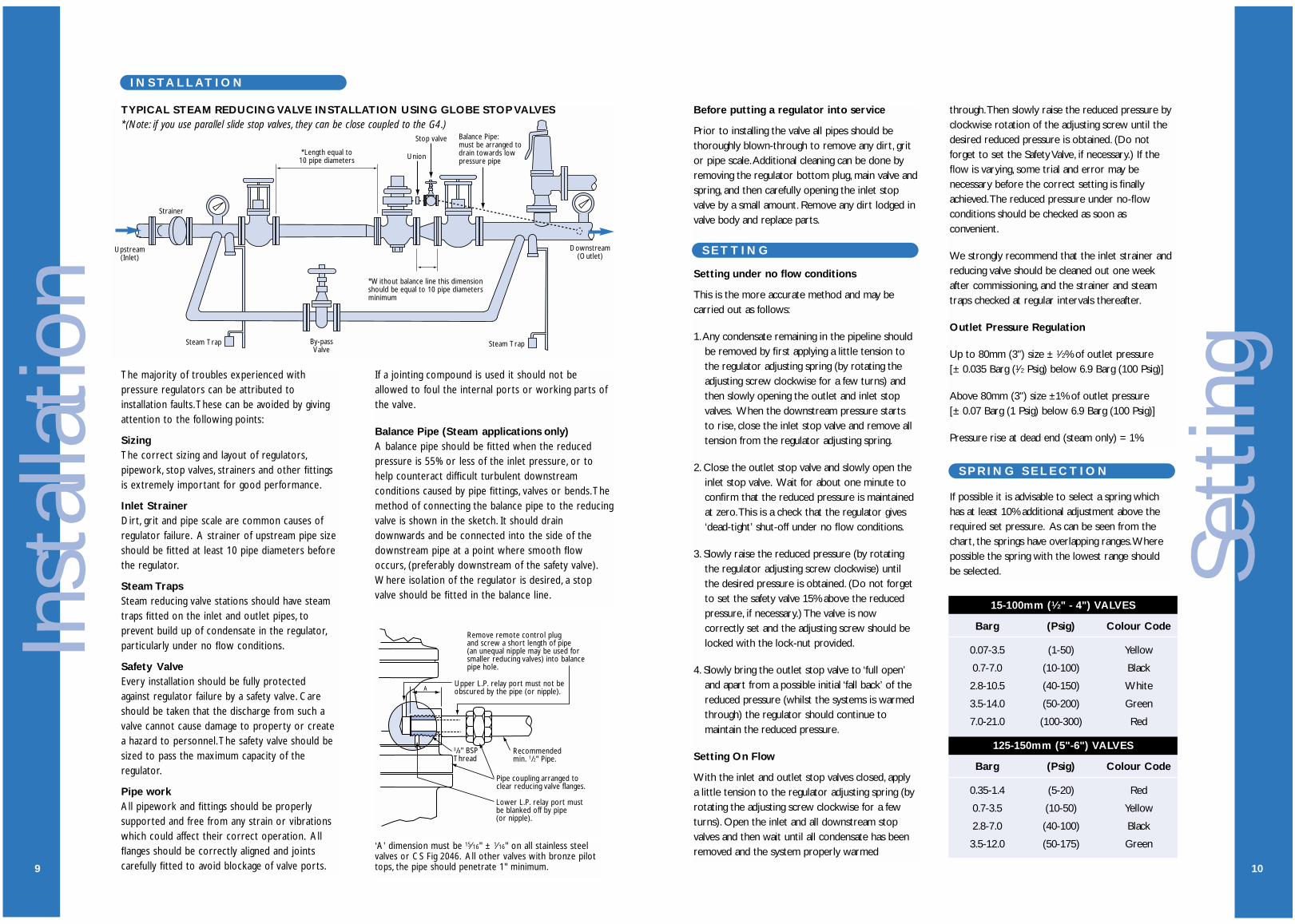
The standard ‘G4’ pilot top can reduce pressuresdown to 0.35 Barg (5 Psig). For pressures belowthis, a bronze low pressure pilot top can be fitted inplace of the standard top. It is suitable for outletpressures from 0.07 to 0.35 Barg (1 to 5 Psig) usingthe yellow spring.The low pressure top is availablefor fitting on to valve sizes 15 to 100mm(1⁄2 to 4 inch), and a balance line should always befitted to a low pressure top, on steam duty andnever on gas duty.
Note: A low pressure top is only suitable for inletpressure up to a maximum of 7 Barg (100 Psig).Higher inlet pressures can be accommodated by useof two G4 valves ‘in-series’, refer to page 8.
The low pressure top can also be supplied as aconversion kit, allowing existing valves and stock tobe modified quickly should the need suddenly arise.O
pera
tion
3
Bailey G4 SeriesP i l o t O p e r a t e d P r e s s u r e R e d u c i n g V a l v e s
. . . E x t r e m e l y s e n s i t i v e a n d a c c u r a t e
O P E R AT I O N
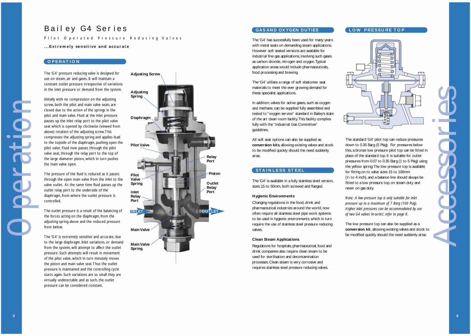
The ‘G4’ pressure reducing valve is designed foruse on steam, air and gases. It will maintain aconstant outlet pressure irrespective of variationsin the inlet pressure or demand from the system.
Initially with no compression on the adjustingscrew, both the pilot and main valve seats areclosed due to the action of the springs in thepilot and main valve. Fluid at the inlet pressurepasses up the inlet relay port to the pilot valveseat which is opened by clockwise (viewed fromabove) rotation of the adjusting screw.Thiscompresses the adjusting spring and applies loadto the topside of the diaphragm, pushing open thepilot valve. Fluid now passes through the pilotvalve seat, through the relay port to the top ofthe large diameter piston, which in turn pushesthe main valve open.
The pressure of the fluid is reduced as it passesthrough the open main valve from the inlet to thevalve outlet. At the same time fluid passes up theoutlet relay port to the underside of thediaphragm, from where the outlet pressure iscontrolled.
The outlet pressure is a result of the balancing ofthe forces acting on the diaphragm, from theadjusting spring above and the reduced pressurefrom below.
The ‘G4’ is extremely sensitive and accurate, dueto the large diaphragm. Inlet variations, or demandfrom the system, will attempt to affect the outletpressure. Such attempts will result in movementof the pilot valve, which in turn minutely movesthe piston and main valve seat.Thus the outletpressure is maintained and the controlling cyclestarts again. Such variations are so small they arevirtually undetectable and as such, the outletpressure can be considered constant.
Adjusting Screw
AdjustingSpring
Diaphragm
Pilot Valve
PilotValveSpring Outlet
RelayPort
RelayPort
Piston
InletRelayPort
Main Valve
Main ValveSpring
INLET OUTLET

Mat
eria
ls
6
1 Bronze Stainless Steel Cast Iron Carbon Steel Carbon Steel
2 Stainless Steel Stainless Steel Stainless Steel Stainless Steel Stainless Steel
3 Stainless Steel Stainless Steel Stainless Steel Stainless Steel Stainless Steel
4 Bronze Stainless Steel Bronze Stainless Steel Stainless Steel
5 Bronze Stainless Steel Bronze Bronze Stainless Steel
6 Bronze PTFE coated St. St. Bronze Bronze Chrome Iron
7 Stainless Steel Stainless Steel Stainless Steel Stainless Steel Stainless Steel
8 Stainless Steel Stainless Steel Stainless Steel Stainless Steel Stainless Steel
17 NAF NAF NAF NAF NAF
21 Stainless Steel Stainless Steel Stainless Steel Stainless Steel Stainless Steel
24 NAF NAF NAF NAF NAF
25 Bronze Stainless Steel Bronze Bronze Steel
26 Stainless Steel Stainless Steel Stainless Steel Stainless Steel Stainless Steel
27 Stainless Steel Stainless Steel Stainless Steel Stainless Steel Stainless Steel
28 Brass Stainless Steel Brass Brass Brass
29 Stainless Steel Stainless Steel Stainless Steel Stainless Steel Stainless Steel
30 Bronze Stainless Steel Bronze Bronze Carbon Steel
31 Stainless Steel Stainless Steel Stainless Steel Stainless Steel Stainless Steel
32 Bronze Stainless Steel Bronze Bronze Carbon Steel
33 Steel Stainless Steel Steel Steel Steel
34 Brass Stainless Steel Brass Brass Brass
35 Brass Stainless Steel Brass Brass Brass
36 Bronze Stainless Steel Bronze Bronze Bronze
37 Bronze Stainless Steel Bronze Bronze Bronze
38 Brass Brass Brass Brass Brass
42 NAF NAF NAF NAF NAF
43 NAF NAF NAF NAF NAF
44 Steel Stainless Steel Stainless Steel Stainless Steel Stainless Steel
48 Stainless Steel Stainless Steel Stainless Steel Stainless Steel Stainless Steel
49 Bronze N/A Bronze Bronze N/A
50 Copper N/A Copper Copper N/A
51 Bronze N/A Bronze Bronze N/A
52 Bronze N/A N/A N/A N/A
53 Monel N/A Monel Monel N/A
54 Steel N/A Steel Steel N/A
55 Steel N/A Steel Steel N/A
61 Nylon Zinc alloy Nylon Nylon Nylon
68 Copper NAF Copper Copper Copper
69 Brass Stainless Steel Bronze Bronze Carbon Steel
70 NAF NAF NAF NAF NAF
ITEM 2042 & 2043 2042 & 2043 2044 2045 2046Bronze Stainless Steel Cast Iron Carbon Steel Carbon Steel
Part
s
5
ITEM PART
1 Body
2 Main Valve
3 Main Valve Seat
4 Bottom Plug
5 Piston
6 Piston Rings
7 Piston Liner
8 Piston Guide
17 Valve Body Top Joint
21 Main Valve Spring
24 Bottom Plug Joint
25 Pilot Valve Top
26 Pilot Valve
27 Pilot Valve Plug
28 Pilot Valve Cap
29 Diaphragm
30 H.P. Port Plug
31 Pilot Valve Spring
32 Pilot Valve Top Cover
33 Adjusting Spring
34 Adjusting Spring Bottom Plate
35 Adjusting Spring Top Plate
36 Adjusting Screw
37 Locking Ring
38 Padlock
42 Diaphragm Joint
43 H.P. Port Plug Joint
44 Cap Headed Screws
48 Pilot Valve Head
49 L.P. Diaphragm
50 L.P. Screw Joint
51 L.P. Adaptor Flange
52 L.P. Top Cover
53 L.P. Push Rod
54 L.P. Top Cover Bolts
55 L.P. Top Cover Nuts
61 Top Cap
68 Pilot Valve Plug Joint
69 Remote Control Plug
70 Remote Control Plug Joint
Note: Items 2 and 26 are Stainless Steel forsteam duty, but on air and gas duties theyhave a variety of elastomeric or PTFE seats, tosuit the application.
36
37
38
32
34
42
28
25
26
30
43
7
5
1
2
24
35
61
33
29
27
6848
69
70
17
31
6
8
3
21
4
INLET
INLET
OUTLET
OUTLET
1
54
49
52
50
44
51
55
53

8
‘ IN SERIES ’ INSTALLATIONS
‘IN PARALLEL’ INSTALLATIONSD I A P H R AG M S
One diaphragm is required for reduced pressuresup to 10.5 Barg (150 Psig), but two are requiredfor reduced pressure above this figure.
Multiple valves installed ‘In Series’ should beconsidered for applications when high pressuredrops are required. If the required outlet pressureis less than the minimum shown in the charts twovalves can be used.
An ‘In Series’ installation should be designed todrop the pressure in at least two steps/stages.
A typical diagram is shown (using globe typeisolating valves).
Multiple valves can be installed as an ‘in parallel’system when the system has a very large variationin the required capacity. On such a system one largeand one small valve should be installed, with acombined capacity greater than the maximumrequired demand, the smaller valve having a capacityjust greater than the minimum required demand.
Setting the smaller valve slightly higher than thelarger valve, will ensure that the larger valve isclosed at low flow rates. Increasing demand willthen open the larger valve as outlet pressure falls toits set point.
A typical diagram is shown (using close coupledparallel slide isolating valves).
‘IN SERIES’ INSTALLATION
‘IN PARALLEL’ INSTALLATION
* *
*
*Balance lines are only required on some steam applications, they are not required on air/gas applications.
Acc
esso
ries
7
S PA R E S
For Steam Applications
The ‘G4’ is a self-actuated, pilot operated pressurereducing valve and it relies upon a stable pressuresignal from the outlet pipe work in order tomaintain stable control of the outlet pressure.
However, under certain conditions the signalpressure may be unstable in the immediate vicinityof the valve outlet and as a result may causeerratic control.
This can easily be overcome by installing a balancepipe from the remote sensing port to a straightsection of the outlet pipe where stable flow hasbeen resumed (see diagram below).
Ideally the balance pipe should be a minimum of2 metres (6 feet) long and must be screwed intothe remote sensing port to the required depth, seepage 9. It should also include a pipe union and stopvalve to allow dismantling and isolation. It shouldbe installed with a steady fall away from the
reducing valve, to facilitateself drainage of condensate.
We recommend fitting a balance pipe:
1. When the reduced pressure is below 55% of theinlet pressure.
2. When a low pressure top is fitted.
3. When difficult outlet pipe work conditions occur.
We do not recommend fitting a balance pipe on gasapplications.To ensure correct operation the G4should be mounted at least 10 pipe diameters fromrestrictions such as other valves or bends.
Unstable Flow
Routine Service Pack:1 Diaphragm1 Set of Piston Rings1 Pilot Valve Cap1 Set of Joints
Complete Repair kit:1 Diaphragm1 Set of Piston Rings1 Pilot Valve Assembly1 Main Valve1 Main Valve Seat1 Main Valve Spring1 Set of Joints1 Pilot Valve Cap
Each carton of spares contains a leaflet, which not only identifiesthe parts supplied, but also has a recommended list of ‘check-points’ to help identify common causes of reducing valve trouble.
Remove remote sensing plug andgasket and screw a short lengthof pipe into the remote control port.
See page 9for MinimumInsert
Pipe unionarranged to clearreducing valveflanges.
Recommendedmin. 1/2" pipe.
Low pressure relayport must beblanked off by pipe.
R E M OT E P R E S S U R E S E N S I N G
Pipe union.
Stop valve.
Balance pipe toenter side of pipe.
Balance pipe to slopeaway from valve.
Port to be blockedby pipe.
Stable Flow
Before putting a regulator into service
Prior to installing the valve all pipes should bethoroughly blown-through to remove any dirt, gritor pipe scale.Additional cleaning can be done byremoving the regulator bottom plug, main valve andspring, and then carefully opening the inlet stopvalve by a small amount. Remove any dirt lodged invalve body and replace parts.
Setting under no flow conditions
This is the more accurate method and may becarried out as follows:
1.Any condensate remaining in the pipeline shouldbe removed by first applying a little tension tothe regulator adjusting spring (by rotating theadjusting screw clockwise for a few turns) andthen slowly opening the outlet and inlet stopvalves. When the downstream pressure startsto rise, close the inlet stop valve and remove alltension from the regulator adjusting spring.
2. Close the outlet stop valve and slowly open theinlet stop valve. Wait for about one minute toconfirm that the reduced pressure is maintainedat zero.This is a check that the regulator gives‘dead-tight’ shut-off under no flow conditions.
3. Slowly raise the reduced pressure (by rotatingthe regulator adjusting screw clockwise) untilthe desired pressure is obtained. (Do not forgetto set the safety valve 15% above the reducedpressure, if necessary.) The valve is nowcorrectly set and the adjusting screw should belocked with the lock-nut provided.
4. Slowly bring the outlet stop valve to ‘full open’and apart from a possible initial ‘fall back’ of thereduced pressure (whilst the systems is warmedthrough) the regulator should continue tomaintain the reduced pressure.
Setting On Flow
With the inlet and outlet stop valves closed, applya little tension to the regulator adjusting spring (byrotating the adjusting screw clockwise for a fewturns). Open the inlet and all downstream stopvalves and then wait until all condensate has beenremoved and the system properly warmed
Sett
ing
10
S E T T I N G
S P R I N G S E L E C T I O N
through.Then slowly raise the reduced pressure byclockwise rotation of the adjusting screw until thedesired reduced pressure is obtained. (Do notforget to set the Safety Valve, if necessary.) If theflow is varying, some trial and error may benecessary before the correct setting is finallyachieved.The reduced pressure under no-flowconditions should be checked as soon asconvenient.
We strongly recommend that the inlet strainer andreducing valve should be cleaned out one weekafter commissioning, and the strainer and steamtraps checked at regular intervals thereafter.
Outlet Pressure Regulation
Up to 80mm (3") size ± 1⁄2% of outlet pressure[± 0.035 Barg (1⁄2 Psig) below 6.9 Barg (100 Psig)]
Above 80mm (3") size ±1% of outlet pressure[± 0.07 Barg (1 Psig) below 6.9 Barg (100 Psig)]
Pressure rise at dead end (steam only) = 1%.
If possible it is advisable to select a spring whichhas at least 10% additional adjustment above therequired set pressure. As can be seen from thechart, the springs have overlapping ranges.Wherepossible the spring with the lowest range shouldbe selected.
15-100mm (1⁄2" - 4") VALVES
Barg (Psig) Colour Code
0.07-3.5 (1-50) Yellow
0.7-7.0 (10-100) Black
2.8-10.5 (40-150) White
3.5-14.0 (50-200) Green
7.0-21.0 (100-300) Red
125-150mm (5"-6") VALVES
Barg (Psig) Colour Code
0.35-1.4 (5-20) Red
0.7-3.5 (10-50) Yellow
2.8-7.0 (40-100) Black
3.5-12.0 (50-175) Green
Inst
alla
tion
9
I N S TA L L AT I O N
Steam Trap
Upstream(Inlet)
Strainer
Balance Pipe:must be arranged todrain towards lowpressure pipe
*Without balance line this dimensionshould be equal to 10 pipe diametersminimum
*Length equal to10 pipe diameters
Downstream(Outlet)
By-passValve
Union
Stop valve
Steam Trap
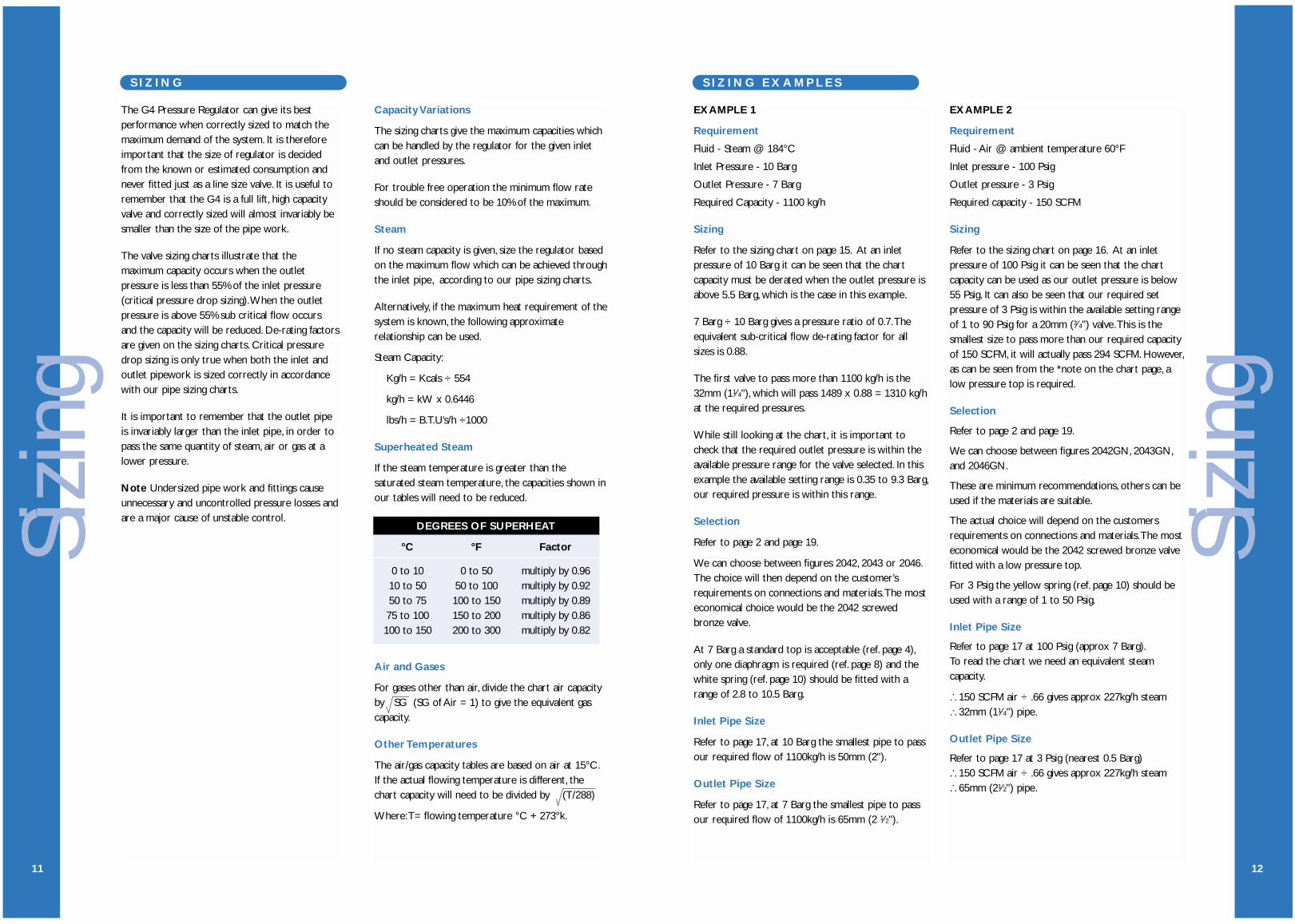
TYPICAL STEAM REDUCING VALVE INSTALLATION USING GLOBE STOP VALVES
The majority of troubles experienced withpressure regulators can be attributed toinstallation faults.These can be avoided by givingattention to the following points:
SizingThe correct sizing and layout of regulators,pipework, stop valves, strainers and other fittingsis extremely important for good performance.
Inlet StrainerDirt, grit and pipe scale are common causes ofregulator failure. A strainer of upstream pipe sizeshould be fitted at least 10 pipe diameters beforethe regulator.
Steam TrapsSteam reducing valve stations should have steamtraps fitted on the inlet and outlet pipes, toprevent build up of condensate in the regulator,particularly under no flow conditions.
Safety ValveEvery installation should be fully protectedagainst regulator failure by a safety valve. Careshould be taken that the discharge from such avalve cannot cause damage to property or createa hazard to personnel.The safety valve should besized to pass the maximum capacity of theregulator.
Pipe workAll pipework and fittings should be properlysupported and free from any strain or vibrationswhich could affect their correct operation. Allflanges should be correctly aligned and jointscarefully fitted to avoid blockage of valve ports.
If a jointing compound is used it should not beallowed to foul the internal ports or working parts ofthe valve.
Balance Pipe (Steam applications only)A balance pipe should be fitted when the reducedpressure is 55% or less of the inlet pressure, or tohelp counteract difficult turbulent downstreamconditions caused by pipe fittings, valves or bends.Themethod of connecting the balance pipe to the reducingvalve is shown in the sketch. It should draindownwards and be connected into the side of thedownstream pipe at a point where smooth flowoccurs, (preferably downstream of the safety valve).Where isolation of the regulator is desired, a stopvalve should be fitted in the balance line.
Remove remote control plug and screw a short length of pipe(an unequal nipple may be used forsmaller reducing valves) into balancepipe hole.
Upper L.P. relay port must not beobscured by the pipe (or nipple).
Recommendedmin. 1/2" Pipe.
3/8" BSPThread
Pipe coupling arranged toclear reducing valve flanges.
Lower L.P. relay port mustbe blanked off by pipe(or nipple).
A
‘A’ dimension must be 15⁄16" ± 1⁄16" on all stainless steelvalves or CS Fig 2046. All other valves with bronze pilottops, the pipe should penetrate 1" minimum.
*(Note: if you use parallel slide stop valves, they can be close coupled to the G4.)
Sizi
ng
12
S I Z I N G E X A M P L E S
EXAMPLE 1
Requirement
Fluid - Steam @ 184°C
Inlet Pressure - 10 Barg
Outlet Pressure - 7 Barg
Required Capacity - 1100 kg/h
Sizing
Refer to the sizing chart on page 15. At an inletpressure of 10 Barg it can be seen that the chartcapacity must be derated when the outlet pressure isabove 5.5 Barg, which is the case in this example.
7 Barg ÷ 10 Barg gives a pressure ratio of 0.7.Theequivalent sub-critical flow de-rating factor for allsizes is 0.88.
The first valve to pass more than 1100 kg/h is the32mm (11⁄4"), which will pass 1489 x 0.88 = 1310 kg/hat the required pressures.
While still looking at the chart, it is important tocheck that the required outlet pressure is within theavailable pressure range for the valve selected. In thisexample the available setting range is 0.35 to 9.3 Barg,our required pressure is within this range.
Selection
Refer to page 2 and page 19.
We can choose between figures 2042, 2043 or 2046.The choice will then depend on the customer’srequirements on connections and materials.The mosteconomical choice would be the 2042 screwedbronze valve.
At 7 Barg a standard top is acceptable (ref. page 4),only one diaphragm is required (ref. page 8) and thewhite spring (ref. page 10) should be fitted with arange of 2.8 to 10.5 Barg.
Inlet Pipe Size
Refer to page 17, at 10 Barg the smallest pipe to passour required flow of 1100kg/h is 50mm (2").
Outlet Pipe Size
Refer to page 17, at 7 Barg the smallest pipe to passour required flow of 1100kg/h is 65mm (2 1⁄2").
EXAMPLE 2
Requirement
Fluid - Air @ ambient temperature 60°F
Inlet pressure - 100 Psig
Outlet pressure - 3 Psig
Required capacity - 150 SCFM
Sizing
Refer to the sizing chart on page 16. At an inletpressure of 100 Psig it can be seen that the chartcapacity can be used as our outlet pressure is below55 Psig. It can also be seen that our required setpressure of 3 Psig is within the available setting rangeof 1 to 90 Psig for a 20mm (3⁄4") valve.This is thesmallest size to pass more than our required capacityof 150 SCFM, it will actually pass 294 SCFM. However,as can be seen from the *note on the chart page, alow pressure top is required.
Selection
Refer to page 2 and page 19.
We can choose between figures 2042GN, 2043GN,and 2046GN.
These are minimum recommendations, others can beused if the materials are suitable.
The actual choice will depend on the customersrequirements on connections and materials.The mosteconomical would be the 2042 screwed bronze valvefitted with a low pressure top.
For 3 Psig the yellow spring (ref. page 10) should beused with a range of 1 to 50 Psig.
Inlet Pipe Size
Refer to page 17 at 100 Psig (approx 7 Barg).To read the chart we need an equivalent steamcapacity.
... 150 SCFM air ÷ .66 gives approx 227kg/h steam
... 32mm (11⁄4") pipe.
Outlet Pipe Size
Refer to page 17 at 3 Psig (nearest 0.5 Barg)... 150 SCFM air ÷ .66 gives approx 227kg/h steam... 65mm (21⁄2") pipe.
Sizi
ng
11
S I Z I N G
The G4 Pressure Regulator can give its bestperformance when correctly sized to match themaximum demand of the system. It is thereforeimportant that the size of regulator is decidedfrom the known or estimated consumption andnever fitted just as a line size valve. It is useful toremember that the G4 is a full lift, high capacityvalve and correctly sized will almost invariably besmaller than the size of the pipe work.
The valve sizing charts illustrate that themaximum capacity occurs when the outletpressure is less than 55% of the inlet pressure(critical pressure drop sizing).When the outletpressure is above 55% sub critical flow occursand the capacity will be reduced. De-rating factorsare given on the sizing charts. Critical pressuredrop sizing is only true when both the inlet andoutlet pipework is sized correctly in accordancewith our pipe sizing charts.
It is important to remember that the outlet pipeis invariably larger than the inlet pipe, in order topass the same quantity of steam, air or gas at alower pressure.
Note Undersized pipe work and fittings causeunnecessary and uncontrolled pressure losses andare a major cause of unstable control.
Capacity Variations
The sizing charts give the maximum capacities whichcan be handled by the regulator for the given inletand outlet pressures.
For trouble free operation the minimum flow rateshould be considered to be 10% of the maximum.
Steam
If no steam capacity is given, size the regulator basedon the maximum flow which can be achieved throughthe inlet pipe, according to our pipe sizing charts.
Alternatively, if the maximum heat requirement of thesystem is known, the following approximaterelationship can be used.
Steam Capacity:
Kg/h = Kcals ÷ 554
kg/h = kW x 0.6446
lbs/h = B.T.U’s/h ÷1000
Superheated Steam
If the steam temperature is greater than thesaturated steam temperature, the capacities shown inour tables will need to be reduced.
Air and Gases
For gases other than air, divide the chart air capacityby SG (SG of Air = 1) to give the equivalent gascapacity.
Other Temperatures
The air/gas capacity tables are based on air at 15°C.If the actual flowing temperature is different, thechart capacity will need to be divided by (T/288)
Where:T= flowing temperature °C + 273°k.
DEGREES OF SUPERHEAT
°C °F Factor
0 to 10 0 to 50 multiply by 0.9610 to 50 50 to 100 multiply by 0.9250 to 75 100 to 150 multiply by 0.8975 to 100 150 to 200 multiply by 0.86100 to 150 200 to 300 multiply by 0.82

Surp
lus/M
ainta
inin
g Valv
e
14
S U R P L U S M A I N TA I N I N G VA LV E S E L E C T I O N
VA LV E P E R F O R M A N C E
D I A P H R AG M S
Example 1: Surplus duty (see figure 1)
A steam boiler normally working at a pressure of 10Barg, delivers steam to a critical process which mustnot fall below 8 Barg (closing pressure) in order topreserve correct operation. The excess (surplus)capacity produced can be used for a non-criticalservice. If this non-critical service requires 3500Kg/h of saturated steam, what size of G4 surplusvalve will be required?
A surplus valve is normally sized on the minimumallowable pressure drop across the valve ie: at anequivalent pressure equal to the maximum outletsetting of the valve. Looking at page 15 and the 10Barg inlet pressure, the maximum outlet setting is 9barg for 21⁄2" to 4" valves.This gives a pressure ratioof (9⁄10) 0.9, hence a derating factor of 0.48.To read
the chart, divide the required flow of 3500kg/h by0.48 to give an equivalent chart flow of 7292kg/h. Itcan be seen that the 80mm (3") valve will pass amaximum flow of 7398kg/h which is derated to anactual flow of 3551kg/h (ie 7398 x 0.48).
Example 2: Pressure maintaining duty(see figure 2).
A steam boiler, normally working at a pressure of10 Barg, delivers steam to a process. It isdetermined that the boiler pressure must not fallbelow 8 Barg. The process normally requires3500 Kg/h of saturated steam, what size of G4maintaining valve will be required?
Selecting a pressure maintaining valve is the sameas selecting a surplus valve, therefore follow thesame sizing procedure.
A small pressure rise (accumulation) above the setpoint is required to fully open the valve, and a smallpressure drop (regulation) below the set pressure isrequired to close the valve. It is therefore importantto set the valve higher than the pressure at whichthe valve must be closed, to allow for this regulation.
In the above examples the valve must be set at aminimum of 8.15 Barg.This allows for the regulationof 0.15 Barg to ensure the valve is fully closed at8 Barg. It can also be seen that the valve will be fullyopen by 8.35 Barg (i.e. 0.2 Barg accumulation abovethe set point of 8.15 Barg).
Spring selection
If possible, it is advisable to select a spring which hasat least 10% adjustment above the required setpressure.As can be seen from the chart, the springshave overlapping ranges and therefore, wherepossible, the spring with the lowest pressure rangeshould be selected.
In the examples we require a spring for a pressure of8.1 Barg (ideally plus 10%, say 9 Barg). As can beseen the white, green and red springs can do thispressure, however the white spring should beselected as it has the lower range.
Valve selection
Referring to the charts on page 2 and page 20, it canbe seen that the figures 2044 and 2045 are suitablefor the given conditions.
Fully Open
Set Point
Fully Closed
Accumulation
Regulation
Closing Pressure Accumulation Regulation
Barg (Psig) Barg (Psig) Barg (Psig)
0.35 - 3.5 (5 - 50) 0.10 (1.5) 0.04 (0.5)3.5 - 7.0 (50 - 100) 0.10 (1.5) 0.10 (1.5)7.0 - 10.3 (100 - 150) 0.20 (3.0) 0.15 (2.0)10.3 - 20.7 (150 - 300) 0.50 (7.0) 0.70 (10.0)
SpringColour Code Spring Pressure Range
Barg (Psig)
Yellow 0.35 - 3.5 (5 - 50)Black 0.7 - 7.0 (10 - 100)White 2.8 - 10.3 (40 - 150)Green 3.5 - 14.0 (50 - 200)Red 7.0 - 20.7 (100 - 300)
For pressures above 10.3 Barg (150 Psig)two diaphragms must be fitted. Below this pressureonly one diaphragm is fitted.
Surp
lus/M
ainta
inin
g Valv
e
13
S U R P L U S / M A I N TA I N I N G VA LV E
The ‘G4 surplus’ valve can also be described as a‘pressure maintaining’ or ‘pressure sustaining’ valve.
In these days of high energy costs and environmentemission controls, steam and air systems can bevery expensive to install and run. Often mostindustrial applications need steam or air for themain process plant and it is critical to maintain thesupply to these processes.Additionally, such plantswill also have other demands of a less critical naturesuch as compressed air lines, heating and cleaningsystems.
Obviously two separate systems could be employed,providing that the necessary funds are available toinstall and run both.Alternatively the secondary andless critical applications can be run from the surplusgenerated from the main system. However, duringperiods of extreme demand the main process couldbe starved of steam or air, resulting in productiondisruption and product loss. (See figure 1).
The solution is to fit a ‘G4 surplus’ valve.
The ‘G4 surplus’ valve is designed to be installed inbranch lines to non-essential equipment(see figure 1), to maintain the upstream pressure,thus maintaining the supply to the more vitalprocess and subsequently maintaining productionfrom the system. Alternatively to dump flow surplusto requirements, to a drain or atmosphere.
Additionally if the pressure in a boiler or airaccumulator is allowed to fall too low, a lot ofenergy will be required to build up the pressureonce again (see figure 2).
The solution is to fit a ‘G4 Maintaining’ valve.
The ‘G4 Maintaining’ valve is designed to be installedin the main pipeline from the boiler or an aircompressor (see figure 2), to maintain the pressure inthe boiler or accumulator, thus preventing the boileror accumulator from becoming exhausted.
Operation
The inlet pressure is directed under the diaphragm.A small increase in pressure above the set pressurelifts the diaphragm and opens the pilot valve, which inturn opens the main valve. Subsequently when excessdemand drops the pressure below the required level,the adjusting spring will overcome the pressure underthe diaphragm and close the pilot valve.This in turncauses the main valve to close, thus cutting thesurplus supply and/or maintaining pressure in themain line, boiler or accumulator.
This duty and valve type is known by many names.As can be seen in this text the valve ‘maintains’ or‘sustains’ pressure in the main line, boiler oraccumulator and can use ‘surplus’ pressure for non-essential services.
Steam/Air MainBoiler orCompressor
Maintaining(Sustaining)
Valve
Figure 1When the G4 surplus valve is closed, thefull flow from boiler/compressor goes tothe critical process.
Figure 2When the G4 maintaining valve is closed,the full flow from boiler/compressor isstopped and the minimum pressure of theboiler/accumulator is maintained.
Steam/Air Main CriticalProcess
Boiler orCompressor
Surplus Valve
To Non-CriticalService or Drain
Imperial Capacity16
(P1) (P2) OUTLET PRESSURE PsigInlet Derate Maximum setting Minimum setting
Pressure capacity 15–50mm 65–100mm 125–150mm 15–50mm 65–100mm 125–150mm
Psig if above 1⁄2 to 2" 21⁄2" to 4" 5 to 6" 1⁄2 to 2" 21⁄2" to 4" 5 to 6"
‡10 N/a 5 N/a N/a *1 N/a N/a
20 11 15 10 10 *1 *1 *5
30 16.5 25 20 20 *1 *1 *5
40 22 35 30 30 *1 *1 *5
50 27.5 45 40 40 *1 *1 *5
60 33 50 45 45 *1 *1 *5
70 38.5 60 55 55 *1 *1 *5
80 44 70 65 65 *1 *1 *5
90 49.5 80 75 75 *1 *1 *5
100 55 90 85 85 *1 *1 *5
200 110 185 †185 174 10 10 40
300 165 285 †285 174 20 50 70
400 220 300 †300 174 55 95 105
500 275 300 †300 174 90 110 140
600 N/a 300 †300 174 90 120 150
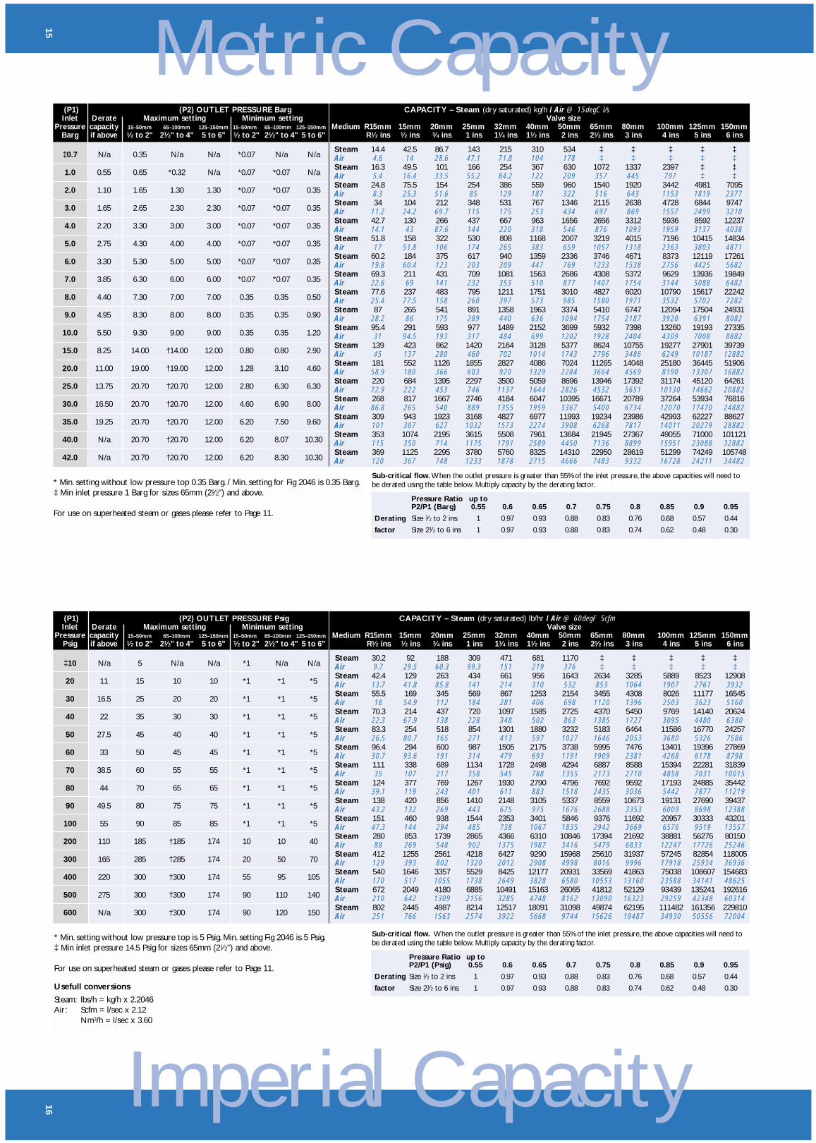
CAPACITY – Steam (dry saturated) lb/hr / Air @ 60degF ScfmValve size
Medium R15mm 15mm 20mm 25mm 32mm 40mm 50mm 65mm 80mm 100mm 125mm 150mmR1⁄2 ins 1⁄2 ins 3⁄4 ins 1 ins 11⁄4 ins 11⁄2 ins 2 ins 21⁄2 ins 3 ins 4 ins 5 ins 6 ins
Steam 30.2 92 188 309 471 681 1170 ‡ ‡ ‡ ‡ ‡Air 9.7 29.5 60.3 99.3 151 219 376 ‡ ‡ ‡ ‡ ‡Steam 42.4 129 263 434 661 956 1643 2634 3285 5889 8523 12908Air 13.7 41.8 85.8 141 214 310 532 853 1064 1907 2761 3932Steam 55.5 169 345 569 867 1253 2154 3455 4308 8026 11177 16545Air 18 54.9 112 184 281 406 698 1120 1396 2503 3623 5160Steam 70.3 214 437 720 1097 1585 2725 4370 5450 9769 14140 20624Air 22.3 67.9 138 228 348 502 863 1385 1727 3095 4480 6380Steam 83.3 254 518 854 1301 1880 3232 5183 6464 11586 16770 24257Air 26.5 80.7 165 271 413 597 1027 1646 2053 3680 5326 7586Steam 96.4 294 600 987 1505 2175 3738 5995 7476 13401 19396 27869Air 30.7 93.6 191 314 479 693 1191 1909 2381 4268 6178 8798Steam 111 338 689 1134 1728 2498 4294 6887 8588 15394 22281 31839Air 35 107 217 358 545 788 1355 2173 2710 4858 7031 10015Steam 124 377 769 1267 1930 2790 4796 7692 9592 17193 24885 35442Air 39.1 119 243 401 611 883 1518 2435 3036 5442 7877 11219Steam 138 420 856 1410 2148 3105 5337 8559 10673 19131 27690 39437Air 43.2 132 269 443 675 975 1676 2688 3353 6009 8698 12388Steam 151 460 938 1544 2353 3401 5846 9376 11692 20957 30333 43201Air 47.3 144 294 485 738 1067 1835 2942 3669 6576 9519 13557Steam 280 853 1739 2865 4366 6310 10846 17394 21692 38881 56276 80150Air 88 269 548 902 1375 1987 3416 5479 6833 12247 17726 25246Steam 412 1255 2561 4218 6427 9290 15968 25610 31937 57245 82854 118005Air 129 393 802 1320 2012 2908 4998 8016 9996 17918 25934 36936Steam 540 1646 3357 5529 8425 12177 20931 33569 41863 75038 108607 154683Air 170 517 1055 1738 2649 3828 6580 10553 13160 23588 34141 48625Steam 672 2049 4180 6885 10491 15163 26065 41812 52129 93439 135241 192616Air 210 642 1309 2156 3285 4748 8162 13090 16323 29259 42348 60314Steam 802 2445 4987 8214 12517 18091 31098 49874 62195 111482 161356 229810Air 251 766 1563 2574 3922 5668 9744 15626 19487 34930 50556 72004
* Min. setting without low pressure top is 5 Psig. Min. setting Fig 2046 is 5 Psig.‡ Min inlet pressure 14.5 Psig for sizes 65mm (21⁄2") and above.
For use on superheated steam or gases please refer to Page 11.
Usefull conversions
Steam: lbs/h = kg/h x 2.2046Air: Scfm = l/sec x 2.12
Nm3/h = l/sec x 3.60
Sub-critical flow. When the outlet pressure is greater than 55% of the inlet pressure, the above capacities will need tobe derated using the table below. Multiply capacity by the derating factor.
Pressure Ratio up toP2/P1 (Psig) 0.55 0.6 0.65 0.7 0.75 0.8 0.85 0.9 0.95
Derating Size 1⁄2 to 2 ins 1 0.97 0.93 0.88 0.83 0.76 0.68 0.57 0.44
factor Size 21⁄2 to 6 ins 1 0.97 0.93 0.88 0.83 0.74 0.62 0.48 0.30
Metric Capacity
15
* Min. setting without low pressure top 0.35 Barg. / Min. setting for Fig 2046 is 0.35 Barg.‡ Min inlet pressure 1 Barg for sizes 65mm (21⁄2") and above.
For use on superheated steam or gases please refer to Page 11.
Sub-critical flow. When the outlet pressure is greater than 55% of the inlet pressure, the above capacities will need tobe derated using the table below. Multiply capacity by the derating factor.
Pressure Ratio up toP2/P1 (Barg) 0.55 0.6 0.65 0.7 0.75 0.8 0.85 0.9 0.95
Derating Size 1⁄2 to 2 ins 1 0.97 0.93 0.88 0.83 0.76 0.68 0.57 0.44
factor Size 21⁄2 to 6 ins 1 0.97 0.93 0.88 0.83 0.74 0.62 0.48 0.30
(P1) (P2) OUTLET PRESSURE BargInlet Derate Maximum setting Minimum setting
Pressure capacity 15–50mm 65–100mm 125–150mm 15–50mm 65–100mm 125–150mm
Barg if above 1⁄2 to 2" 21⁄2" to 4" 5 to 6" 1⁄2 to 2" 21⁄2" to 4" 5 to 6"
‡0.7 N/a 0.35 N/a N/a *0.07 N/a N/a
1.0 0.55 0.65 *0.32 N/a *0.07 *0.07 N/a
2.0 1.10 1.65 1.30 1.30 *0.07 *0.07 0.35
3.0 1.65 2.65 2.30 2.30 *0.07 *0.07 0.35
4.0 2.20 3.30 3.00 3.00 *0.07 *0.07 0.35
5.0 2.75 4.30 4.00 4.00 *0.07 *0.07 0.35
6.0 3.30 5.30 5.00 5.00 *0.07 *0.07 0.35
7.0 3.85 6.30 6.00 6.00 *0.07 *0.07 0.35
8.0 4.40 7.30 7.00 7.00 0.35 0.35 0.50
9.0 4.95 8.30 8.00 8.00 0.35 0.35 0.90
10.0 5.50 9.30 9.00 9.00 0.35 0.35 1.20
15.0 8.25 14.00 †14.00 12.00 0.80 0.80 2.90
20.0 11.00 19.00 †19.00 12.00 1.28 3.10 4.60
25.0 13.75 20.70 †20.70 12.00 2.80 6.30 6.30
30.0 16.50 20.70 †20.70 12.00 4.60 6.90 8.00
35.0 19.25 20.70 †20.70 12.00 6.20 7.50 9.60
40.0 N/a 20.70 †20.70 12.00 6.20 8.07 10.30
42.0 N/a 20.70 †20.70 12.00 6.20 8.30 10.30
CAPACITY – Steam (dry saturated) kg/h / Air @ 15degC l/sValve size
Medium R15mm 15mm 20mm 25mm 32mm 40mm 50mm 65mm 80mm 100mm 125mm 150mmR1⁄2 ins 1⁄2 ins 3⁄4 ins 1 ins 11⁄4 ins 11⁄2 ins 2 ins 21⁄2 ins 3 ins 4 ins 5 ins 6 ins
Steam 14.4 42.5 86.7 143 215 310 534 ‡ ‡ ‡ ‡ ‡Air 4.6 14 28.6 47.1 71.8 104 178 ‡ ‡ ‡ ‡ ‡Steam 16.3 49.5 101 166 254 367 630 1072 1337 2397 ‡ ‡Air 5.4 16.4 33.5 55.2 84.2 122 209 357 445 797 ‡ ‡Steam 24.8 75.5 154 254 386 559 960 1540 1920 3442 4981 7095Air 8.3 25.3 51.6 85 129 187 322 516 643 1153 1819 2377Steam 34 104 212 348 531 767 1346 2115 2638 4728 6844 9747Air 11.2 24.2 69.7 115 175 253 434 697 869 1557 2499 3210Steam 42.7 130 266 437 667 963 1656 2656 3312 5936 8592 12237Air 14.1 43 87.6 144 220 318 546 876 1093 1959 3137 4038Steam 51.8 158 322 530 808 1168 2007 3219 4015 7196 10415 14834Air 17 51.8 106 174 265 383 659 1057 1318 2363 3803 4871Steam 60.2 184 375 617 940 1359 2336 3746 4671 8373 12119 17261Air 19.8 60.4 123 203 309 447 769 1233 1538 2756 4425 5682Steam 69.3 211 431 709 1081 1563 2686 4308 5372 9629 13936 19849Air 22.6 69 141 232 353 510 877 1407 1754 3144 5088 6482Steam 77.6 237 483 795 1211 1751 3010 4827 6020 10790 15617 22242Air 25.4 77.5 158 260 397 573 985 1580 1971 3532 5702 7282Steam 87 265 541 891 1358 1963 3374 5410 6747 12094 17504 24931Air 28.2 86 175 289 440 636 1094 1754 2187 3920 6391 8082Steam 95.4 291 593 977 1489 2152 3699 5932 7398 13260 19193 27335Air 31 94.5 193 317 484 699 1202 1928 2404 4309 7008 8882Steam 139 423 862 1420 2164 3128 5377 8624 10755 19277 27901 39739Air 45 137 280 460 702 1014 1743 2796 3486 6249 10187 12882Steam 181 552 1126 1855 2827 4086 7024 11265 14048 25180 36445 51906Air 58.9 180 366 603 920 1329 2284 3664 4569 8190 13307 16882Steam 220 684 1395 2297 3500 5059 8696 13946 17392 31174 45120 64261Air 72.9 222 453 746 1137 1644 2826 4532 5651 10130 14662 20882Steam 268 817 1667 2746 4184 6047 10395 16671 20789 37264 53934 76816Air 86.8 265 540 889 1355 1959 3367 5400 6734 12070 17470 24882Steam 309 943 1923 3168 4827 6977 11993 19234 23986 42993 62227 88627Air 101 307 627 1032 1573 2274 3908 6268 7817 14011 20279 28882Steam 353 1074 2195 3615 5508 7961 13684 21945 27367 49055 71000 101121Air 115 350 714 1175 1791 2589 4450 7136 8899 15951 23088 32882Steam 369 1125 2295 3780 5760 8325 14310 22950 28619 51299 74249 105748Air 120 367 748 1233 1878 2715 4666 7483 9332 16728 24211 34482
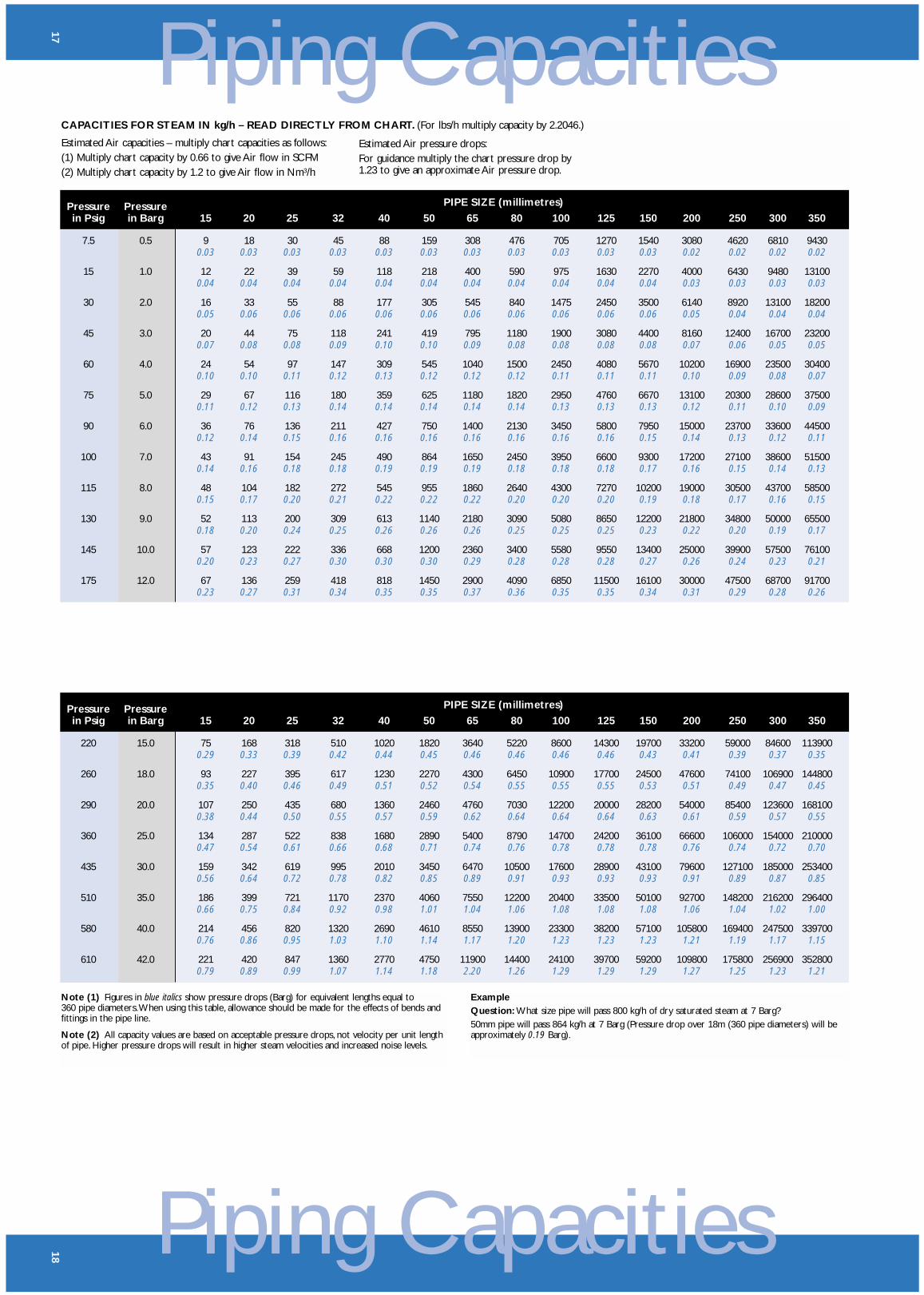
Piping Capacities18
PIPE SIZE (millimetres)Pressure Pressurein Psig in Barg 15 20 25 32 40 50 65 80 100 125 150 200 250 300 350
220 15.0 75 168 318 510 1020 1820 3640 5220 8600 14300 19700 33200 59000 84600 1139000.29 0.33 0.39 0.42 0.44 0.45 0.46 0.46 0.46 0.46 0.43 0.41 0.39 0.37 0.35
260 18.0 93 227 395 617 1230 2270 4300 6450 10900 17700 24500 47600 74100 106900 1448000.35 0.40 0.46 0.49 0.51 0.52 0.54 0.55 0.55 0.55 0.53 0.51 0.49 0.47 0.45
290 20.0 107 250 435 680 1360 2460 4760 7030 12200 20000 28200 54000 85400 123600 1681000.38 0.44 0.50 0.55 0.57 0.59 0.62 0.64 0.64 0.64 0.63 0.61 0.59 0.57 0.55
360 25.0 134 287 522 838 1680 2890 5400 8790 14700 24200 36100 66600 106000 154000 2100000.47 0.54 0.61 0.66 0.68 0.71 0.74 0.76 0.78 0.78 0.78 0.76 0.74 0.72 0.70
435 30.0 159 342 619 995 2010 3450 6470 10500 17600 28900 43100 79600 127100 185000 2534000.56 0.64 0.72 0.78 0.82 0.85 0.89 0.91 0.93 0.93 0.93 0.91 0.89 0.87 0.85
510 35.0 186 399 721 1170 2370 4060 7550 12200 20400 33500 50100 92700 148200 216200 2964000.66 0.75 0.84 0.92 0.98 1.01 1.04 1.06 1.08 1.08 1.08 1.06 1.04 1.02 1.00
580 40.0 214 456 820 1320 2690 4610 8550 13900 23300 38200 57100 105800 169400 247500 3397000.76 0.86 0.95 1.03 1.10 1.14 1.17 1.20 1.23 1.23 1.23 1.21 1.19 1.17 1.15
610 42.0 221 420 847 1360 2770 4750 11900 14400 24100 39700 59200 109800 175800 256900 3528000.79 0.89 0.99 1.07 1.14 1.18 2.20 1.26 1.29 1.29 1.29 1.27 1.25 1.23 1.21
Note (1) Figures in blue italics show pressure drops (Barg) for equivalent lengths equal to360 pipe diameters.When using this table, allowance should be made for the effects of bends andfittings in the pipe line.
Note (2) All capacity values are based on acceptable pressure drops, not velocity per unit lengthof pipe. Higher pressure drops will result in higher steam velocities and increased noise levels.
ExampleQuestion: What size pipe will pass 800 kg/h of dry saturated steam at 7 Barg?50mm pipe will pass 864 kg/h at 7 Barg (Pressure drop over 18m (360 pipe diameters) will beapproximately 0.19 Barg).
Piping Capacities
17
CAPACITIES FOR STEAM IN kg/h – READ DIRECTLY FROM CHART. (For lbs/h multiply capacity by 2.2046.)
Estimated Air capacities – multiply chart capacities as follows:(1) Multiply chart capacity by 0.66 to give Air flow in SCFM(2) Multiply chart capacity by 1.2 to give Air flow in Nm3/h
PIPE SIZE (millimetres)Pressure Pressurein Psig in Barg 15 20 25 32 40 50 65 80 100 125 150 200 250 300 350
7.5 0.5 9 18 30 45 88 159 308 476 705 1270 1540 3080 4620 6810 94300.03 0.03 0.03 0.03 0.03 0.03 0.03 0.03 0.03 0.03 0.03 0.02 0.02 0.02 0.02
15 1.0 12 22 39 59 118 218 400 590 975 1630 2270 4000 6430 9480 131000.04 0.04 0.04 0.04 0.04 0.04 0.04 0.04 0.04 0.04 0.04 0.03 0.03 0.03 0.03
30 2.0 16 33 55 88 177 305 545 840 1475 2450 3500 6140 8920 13100 182000.05 0.06 0.06 0.06 0.06 0.06 0.06 0.06 0.06 0.06 0.06 0.05 0.04 0.04 0.04
45 3.0 20 44 75 118 241 419 795 1180 1900 3080 4400 8160 12400 16700 232000.07 0.08 0.08 0.09 0.10 0.10 0.09 0.08 0.08 0.08 0.08 0.07 0.06 0.05 0.05
60 4.0 24 54 97 147 309 545 1040 1500 2450 4080 5670 10200 16900 23500 304000.10 0.10 0.11 0.12 0.13 0.12 0.12 0.12 0.11 0.11 0.11 0.10 0.09 0.08 0.07
75 5.0 29 67 116 180 359 625 1180 1820 2950 4760 6670 13100 20300 28600 375000.11 0.12 0.13 0.14 0.14 0.14 0.14 0.14 0.13 0.13 0.13 0.12 0.11 0.10 0.09
90 6.0 36 76 136 211 427 750 1400 2130 3450 5800 7950 15000 23700 33600 445000.12 0.14 0.15 0.16 0.16 0.16 0.16 0.16 0.16 0.16 0.15 0.14 0.13 0.12 0.11
100 7.0 43 91 154 245 490 864 1650 2450 3950 6600 9300 17200 27100 38600 515000.14 0.16 0.18 0.18 0.19 0.19 0.19 0.18 0.18 0.18 0.17 0.16 0.15 0.14 0.13
115 8.0 48 104 182 272 545 955 1860 2640 4300 7270 10200 19000 30500 43700 585000.15 0.17 0.20 0.21 0.22 0.22 0.22 0.20 0.20 0.20 0.19 0.18 0.17 0.16 0.15
130 9.0 52 113 200 309 613 1140 2180 3090 5080 8650 12200 21800 34800 50000 655000.18 0.20 0.24 0.25 0.26 0.26 0.26 0.25 0.25 0.25 0.23 0.22 0.20 0.19 0.17
145 10.0 57 123 222 336 668 1200 2360 3400 5580 9550 13400 25000 39900 57500 761000.20 0.23 0.27 0.30 0.30 0.30 0.29 0.28 0.28 0.28 0.27 0.26 0.24 0.23 0.21
175 12.0 67 136 259 418 818 1450 2900 4090 6850 11500 16100 30000 47500 68700 917000.23 0.27 0.31 0.34 0.35 0.35 0.37 0.36 0.35 0.35 0.34 0.31 0.29 0.28 0.26
Estimated Air pressure drops:For guidance multiply the chart pressure drop by1.23 to give an approximate Air pressure drop.
Spec
ifica
tion
20
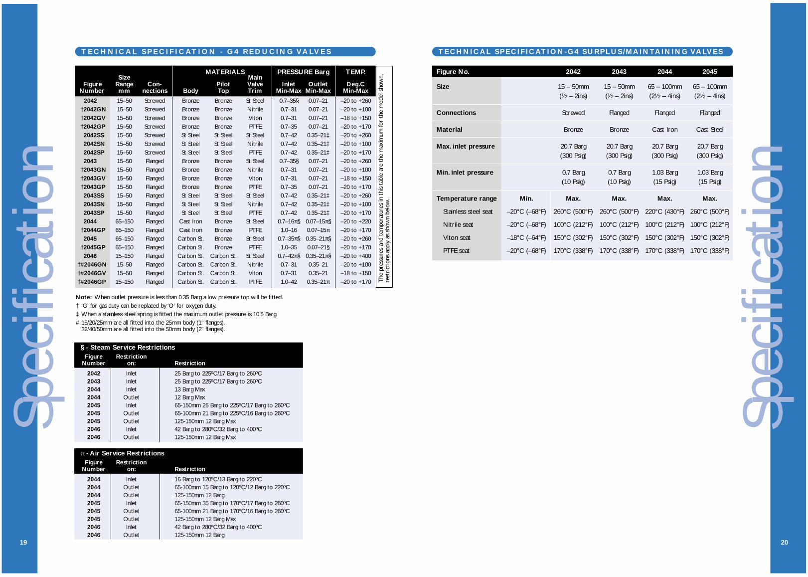
TECHNICAL SPECIFICATION-G4 SURPLUS/MAINTAINING VALVES
Figure No. 2042 2043 2044 2045
Size 15 – 50mm 15 – 50mm 65 – 100mm 65 – 100mm(1⁄2 – 2ins) (1⁄2 – 2ins) (21⁄2 – 4ins) (21⁄2 – 4ins)
Connections Screwed Flanged Flanged Flanged
Material Bronze Bronze Cast Iron Cast Steel
Max. inlet pressure 20.7 Barg 20.7 Barg 20.7 Barg 20.7 Barg(300 Psig) (300 Psig) (300 Psig) (300 Psig)
Min. inlet pressure 0.7 Barg 0.7 Barg 1.03 Barg 1.03 Barg(10 Psig) (10 Psig) (15 Psig) (15 Psig)
Temperature range Min. Max. Max. Max. Max.
Stainless steel seat –20°C (–68°F) 260°C (500°F) 260°C (500°F) 220°C (430°F) 260°C (500°F)
Nitrile seat –20°C (–68°F) 100°C (212°F) 100°C (212°F) 100°C (212°F) 100°C (212°F)
Viton seat –18°C (–64°F) 150°C (302°F) 150°C (302°F) 150°C (302°F) 150°C (302°F)
PTFE seat –20°C (–68°F) 170°C (338°F) 170°C (338°F) 170°C (338°F) 170°C (338°F)
Spec
ifica
tion
19
T E C H N I C A L S P E C I F I C AT I O N - G 4 R E D U C I N G VA LV E S
Note: When outlet pressure is less than 0.35 Barg a low pressure top will be fitted.† ‘G’ for gas duty can be replaced by ‘O’ for oxygen duty.‡ When a stainless steel spring is fitted the maximum outlet pressure is 10.5 Barg.# 15/20/25mm are all fitted into the 25mm body (1" flanges).
32/40/50mm are all fitted into the 50mm body (2" flanges).
MATERIALS PRESSURE Barg TEMP.Size Main
Figure Range Con- Pilot Valve Inlet Outlet Deg.CNumber mm nections Body Top Trim Min-Max Min-Max Min-Max
2042 15–50 Screwed Bronze Bronze St Steel 0.7–35§ 0.07–21 –20 to +260†2042GN 15–50 Screwed Bronze Bronze Nitrile 0.7–31 0.07–21 –20 to +100†2042GV 15–50 Screwed Bronze Bronze Viton 0.7–31 0.07–21 –18 to +150†2042GP 15–50 Screwed Bronze Bronze PTFE 0.7–35 0.07–21 –20 to +1702042SS 15–50 Screwed St Steel St Steel St Steel 0.7–42 0.35–21‡ –20 to +2602042SN 15–50 Screwed St Steel St Steel Nitrile 0.7–42 0.35–21‡ –20 to +1002042SP 15–50 Screwed St Steel St Steel PTFE 0.7–42 0.35–21‡ –20 to +1702043 15–50 Flanged Bronze Bronze St Steel 0.7–35§ 0.07–21 –20 to +260
†2043GN 15–50 Flanged Bronze Bronze Nitrile 0.7–31 0.07–21 –20 to +100†2043GV 15–50 Flanged Bronze Bronze Viton 0.7–31 0.07–21 –18 to +150†2043GP 15–50 Flanged Bronze Bronze PTFE 0.7–35 0.07–21 –20 to +1702043SS 15–50 Flanged St Steel St Steel St Steel 0.7–42 0.35–21‡ –20 to +2602043SN 15–50 Flanged St Steel St Steel Nitrile 0.7–42 0.35–21‡ –20 to +1002043SP 15–50 Flanged St Steel St Steel PTFE 0.7–42 0.35–21‡ –20 to +1702044 65–150 Flanged Cast Iron Bronze St Steel 0.7–16π§ 0.07–15π§ –20 to +220
†2044GP 65–150 Flanged Cast Iron Bronze PTFE 1.0–16 0.07–15π –20 to +1702045 65–150 Flanged Carbon St. Bronze St Steel 0.7–35π§ 0.35–21π§ –20 to +260
†2045GP 65–150 Flanged Carbon St. Bronze PTFE 1.0–35 0.07–21§ –20 to +1702046 15–150 Flanged Carbon St. Carbon St. St Steel 0.7–42π§ 0.35–21π§ –20 to +400
†#2046GN 15–50 Flanged Carbon St. Carbon St. Nitrile 0.7–31 0.35–21 –20 to +100†#2046GV 15–50 Flanged Carbon St. Carbon St. Viton 0.7–31 0.35–21 –18 to +150†#2046GP 15–150 Flanged Carbon St. Carbon St. PTFE 1.0–42 0.35–21π –20 to +170 T
he p
ress
ures
and
tem
pera
ture
s in
thi
s ta
ble
are
the
max
imum
for
the
mod
el s
how
n,re
stri
ctio
ns a
pply
as
show
n be
low
.
§ - Steam Service RestrictionsFigure Restriction
Number on: Restriction
2042 Inlet 25 Barg to 225ºC/17 Barg to 260ºC2043 Inlet 25 Barg to 225ºC/17 Barg to 260ºC2044 Inlet 13 Barg Max2044 Outlet 12 Barg Max2045 Inlet 65-150mm 25 Barg to 225ºC/17 Barg to 260ºC2045 Outlet 65-100mm 21 Barg to 225ºC/16 Barg to 260ºC2045 Outlet 125-150mm 12 Barg Max2046 Inlet 42 Barg to 280ºC/32 Barg to 400ºC2046 Outlet 125-150mm 12 Barg Max
π - Air Service RestrictionsFigure Restriction
Number on: Restriction
2044 Inlet 16 Barg to 120ºC/13 Barg to 220ºC2044 Outlet 65-100mm 15 Barg to 120ºC/12 Barg to 220ºC2044 Outlet 125-150mm 12 Barg2045 Inlet 65-150mm 35 Barg to 170ºC/17 Barg to 260ºC2045 Outlet 65-100mm 21 Barg to 170ºC/16 Barg to 260ºC2045 Outlet 125-150mm 12 Barg Max2046 Inlet 42 Barg to 280ºC/32 Barg to 400ºC2046 Outlet 125-150mm 12 Barg

Dim
ensi
ons
21
D I M E N S I O N S
A A
B
C
Screwed Flanged
A B CDIN
Valve flange Weighttype Size Connection ins mm mm ins mm ins mm kg
15mm 1⁄2" BSP 4.125 105 – 8 203 2.375 60 620mm 3⁄4" BSP 4.125 105 – 8.25 210 2.5 64 6.825mm 1" BSP 4.5 114 – 8.375 213 2.625 67 732mm 11⁄4" BSP 4.875 124 – 9.625 244 3 76 10.840mm 11⁄2" BSP 5.25 133 – 9.875 251 3.125 79 12.750mm 2" BSP 6.375 162 – 10.25 260 3.25 83 15.4
15mm 1⁄2" 5.5 140 130* 8 203 2.375 60 820mm 3⁄4" 5.625 143 150* 8.25 210 2.5 64 8.625mm 1" 6.75 171 160* 8.375 213 2.625 67 932mm 11⁄4" 7 178 180* 9.625 244 3 76 13.640mm 11⁄2" 7.5 191 200* 9.875 251 3.125 79 16.350mm 2" 8.5 216 230* 10.25 260 3.25 83 20.8
65mm 21⁄2" 10 254 254 11.75 298 5.25 133 3580mm 3" 11.25 286 286 12 305 5.75 146 47100mm 4" 13.5 343 343 13.375 340 6.875 175 79125mm 5" 16 406 406 16.75 425 9 229 112150mm 6" 16.5 419 419 17.625 448 9.75 248 159
65mm 21⁄2" 10 254 254 11.25 286 5.125 130 3880mm 3" 11.25 286 286 11.25 286 5.75 146 56100mm 4" 13.5 343 343 12.75 324 7 178 80125mm 5" 16 406 406 15.75 400 8.625 219 107150mm 6" 16.5 419 419 16.5 419 9.75 248 174
15mm 1" 6.75 171 230† 8.375 213 2.75 70 13.520mm 1" 6.75 171 230† 8.375 213 2.75 70 13.525mm 1" 6.75 171 230† 8.375 213 2.75 70 13.532mm 2" 9 229 229 10.5 267 3.5 89 26.340mm 2" 9 229 229 10.5 267 3.5 89 26.350mm 2" 9 229 229 10.5 267 3.5 89 26.365mm 21⁄2" 10 254 254 11.25 286 5.125 130 4280mm 3" 11.25 286 286 11.25 286 5.75 146 52100mm 4" 13.5 343 343 12.75 324 7 178 87125mm 5" 16 406 406 15.75 400 8.625 219 124150mm 6" 16.5 419 419 16.5 419 9.75 248 173
Fig 2042Screwed
Bronze orStainless
Steel
Fig 2043Flanged
Bronze orStainless
Steel
Fig 2044Flanged
Cast Iron(Brz. top)
Fig 2045Flanged
Cast Steel(Brz. top)
Fig 2046Flanged
Cast Steel(C.S. top)
Face to face dimensions are in accordance with *Din 3300 (PN40)†Din 3300 (PN64)
CONNECTION OPTIONS
ScrewedBSP** API/NPT
FlangedBS4504 PN** ANSI, BS10
**Standard item.
G4 SeriesP i l o t O p e r a t e d P r e s s u r eR e d u c i n g V a l v e s
G4
Seri
es
2 0 4 2 S
2 0 4 3 S
2 0 4 4
2 0 4 6
2 0 4 3
2 0 4 5
LOW PRESSURE TOP
2 0 4 2
22