local heat/mass transfer and pressure drop in a two-pass ... · local heat/mass transfer and...
TRANSCRIPT

NASA AVSCOM
Contractor Report 179635 Technical Report 87-C-14
Local Heat/Mass Transfer and Pressure
Drop in a Two-Pass Rib-RoughenedChannel for Turbine Airfoil Cooling
[NASA-CR-17q635) LOCAL IIEAT/MASS _'RANSFER
AND PRESSURE DROP IN _ TWO-PASS
_IB-ROUGHENED CIIAN_EL FOR TI_RBINE _IRFOIL
COOLING Final Report (Texas A_M Univ.} 170
p Awail: NTIS HC A0S/MF A01 CSCL 20D G3/34
N88- 12(i'3g
Unclas010976_
J.C. Han and P.R. Chandra
Texas A & M University
College Station, Texas
September 1987
Prepared for
Lewis Research Center
Under Contract NAS3-24227
Nahonal Aeronauhcs andSpace Administrahon
https://ntrs.nasa.gov/search.jsp?R=19880002657 2018-07-04T15:48:03+00:00Z


i.0 S_
2.0 INTRODUCTION
2.1 Background
2.2 Objective
3.0 EXPERIMENTAL APPARATUS AND DATA REDUCTION
3.1 Experimental Apparatus
3.2 Data Reduction
4.0 EXPERIMENTAL RESULTS AND DISCUSSION
4.1 Experimental Results for the Smooth Channel
4.2 Experimental Results for the Ribbed Channel
4.2.1 Local Mass Transfer Data
4.2.2 Average Mass Transfer Data and Correlations
4.2.3 Comparison with Heat Transfer Data
5.0 PRESSURE DROP MEASUREMENT
5.1 Test Section and Data Analysis
5.2 Results and Discussion
6.0 OONCLUSIONS AND REOOMMENDATIONS
7.0 REFERENCES
APPENDICES
Appendix A: Mass Loss due to Natural Convection
Appendix B: Tabulated Local Mass Transfer Data
Appendix C: Tabulated Local Pressure Drop Data
Page
1
3
3
5
7
7
i0
13
13
16
16
23
26
29
29
31
35
38
85
85
9O
159


D
e
fat
%t
f(FD)
gc
G
%
Kc
Kt
M
Nu
P
.\P
Pw
Pr
Re
Sc
Sh
Sh o
Sh
Sh
t
channel width; also hydraulic diameter
rib height
fully developed average friction factor after the turn
fully developed average friction factor before the turn
fully developed four-sided sn_)oth channel friction factor
conversion factor
mass flux, pV
local mass transfer coefficient, equation (i)
loss coefficient due to contraction
loss coefficient due to sharp turn
local mass transfer rate per unit area, equation (2)
cumulative mass transfer
Nusselt number
rib pitch
pressure drop across the test section
naphthalene vapor pressure at the wall, equation (4)
Prandtl number of air
volumetric flow rate of air
Reynolds number based on channel hydraulic diameter
Schmidt number for naphthalene
local Sherwood number, equation (6)
Sherwood number of fully developed turbulent flow in square
duct
average Sherwood number on each of the channel surfaces
overall average Sherwood number on all surfaces
thickness of the inner (divider) wall
iii
_,EDING PAGE 8LANK NOT FILIJED

At
Tw
V
X
D
P
%
Ps
%
V
duration of the test run
naphthalene wall temperature, equations (3) and (4)
average velocity of air
axial distance from channel entrance
diffusion coefficient, equation (6)
rib angle-of-attack
average density of air
bulk naphthalene vapor density, equation (5)
density of solid naphthalene
local naphthalene vapor density at wall, equation (3)
kinematic viscosity of pure air
iv

1.0
This is an extended research report for the program of Measurement
of Heat Transfer and Pressure Drop in Rectangular Channels with
Turbulence Promoters. This project was conducted by the Turbomachinery
Laboratories of the Texas A&M University and was funded in part through
Curtis Walker at the U.S. Army Research and Technology Laboratories.
The project was monitored by Robert Boyle at the NASA-Lewis Research
Center under NASA Contract No. NAS 3-24227.
Based on the research results from the NASA Contract No. NAS 3-
24227, a final report entitled "Measurement of Heat Transfer and
Pressure Drop in Rectangular Channels with Turbulence Promoters" was
published (NASA CR 4015 September 1986 or AVSOOM TR 86-C-25 by J.C. Han,
J.S. Park, and M.Y. Ibrahim). In that report, the combined effects of
the channel aspect ratio and the rib angle-of-attack on the friction
factor and on the local and the average heat transfer coefficients in
straight, rectangular channel_ with a pair of opposite ribbed walls were
investigated for three Reynolds numbers (Re = 10_000, 30,000 and
60,000), two rib spacings (P/e = i0 and 20), two rib heights (e/D =
0.047 and 0.078), four rib angles (e = 90 ° , 60 ° , 45 ° , and 300), and
three channel aspect ratios CW/H = i, 2, and 3, ribs on side W). The
test channels were heated by passing current through thin stainless
steel foils and instrumented with 180 thermocouples. The local
distributions of the heat transfer coefficient on both the smooth side
and the ribbed side walls from the channel entrance to the downstream
region were measured.
The present investigation was aimed at measuring the _ mass
transfer distributions in a two-pass smooth, square, channel and in a

similar two-_pass square channel with a pair of opposite rib-roughened
walls, via the naphthalene sublimation technique. The top, bottom,
outer, and inner walls of the test channel were all naphthalene-coated
plates. For ribbed channel tests, metallic ribs (with(xlt naphthalene
coating)were placed on the top and bottom walls of the naphthalene-
coated test channel such that the corresponding ribs on the two walls
were directly opposite each other. The highly detailed mass transfer
distributions on the top wall (rib-roughened), the outer wall (smooth),
and the inner wall (smooth) were determined between the channel entrance
and far downstream of the second straight channel, for three Reynolds
numbers (Re = 15,000, 30,000, and 60,000), two rib spacings (P/e = I0
and 20), two rib heights (e/D = 0.063 and 0.094), and three rib angles
(e = 90 °, 60 ° , and 45o). The mass transfer coefficients before the
turn, in the turn, and after the sharp 180 ° turn on each wall of the
test channel were then averaged, compared, and correlated. The
corresponding pressure drops and the friction factors were also measured
and correlated.
2

2.0 _ION
2.1 Background
In advanced gas turbine airfoils, as depicted in Figure i, rib
turbulators are cast onto two opposite walls of internal cooling
passages to enhance the heat transfer to the cooling air. A typical
cooling passagecan be modeled as a straight or a _/_ rectangular
channel with two opposite rib-roughened walls. Han (1984) and Han et
al. (1984, 1985) investigated systematically the effects of the rib
pitch, the rib height, and the rib angle-of-attack on the average heat
transfer and the pressure drop in a fully developed air flow in a
uniformly heated, _ square channel with two opposite ribbed
walls. The results showed that ribs with oblique angles-of-attack (_)
of 30° and 45° provided higher heat transfer enhancement than ribs with
an angle-of-attack of 90° for the same pumping power consumption.
Recently, Han et al. (1986) reported the combined effects of the
channel aspect ratio and the rib angle-of-attack on the friction factor
and on the local and the average heat transfer coefficients in
rectangular channels with a pair of opposite ribbed walls for Reynolds
numbers varying from i0,000 to 60,000. The channel aspect ratio (W/H) was
varied from i to 2 and to 4. The rib height-to-hydraulic diameter ratio
(e/D) was varied from 0.047 to 0.078, the rib pitch-to-height ratio
(P/e) was varied from i0 to 20, and the rib angle-of-attack (e) was
varied from 90 ° to 60 ° to 45 ° and to 30 ° , respectively. The test
channels were heated by passing current through thin stainless steel
foils and instrumented with 180 thermocouples. The local distributions
of the heat transfer coefficient on both the smooth side and the ribbed
side walls from the channel sharp entrance to the downstream region were

measured. The results confirmed that, in the square channel, the heat
transfer for the slant ribs (_= 30° to 45° ) was about 30%higher than
that the transverse ribs (_ = 90° ) for the same pumping power
consumption. However, in the rectangular channels (W/H= 2 and 4, ribs
on side W), the heat transfer at _ = 30° to 45° was only about 5%higher
than that _ = 90°. The results also showedthat, in the square channel,
the highest heat transfer was obtained at e = 60° accompanyingwith the
highest pressure drop, however, in the rectangular channel with W/H = 4,
both the highest heat transfer and pressure drop were obtained at e =
900.
In a _ rectangular channel, in addition to the rib
turbulators, the flow separation and recirculation in the turn around
regions and the flow redevelopment downstream of the turns are expected
to have significant effects on the distribution of the local heat
transfer coefficient and on the overall channel heat transfer. Boyle
(1984) studied the heat transfer in a two-pass square channel with four
smooth walls and in a similar two-pass square channel with two smooth
walls and two opposite ribbed walls (_ = 90o). The top and bottom walls
of the test channels were heated uniformly by passing current through
thin foils and were instrumented with thermocouples, while the other two
walls were unheated. The results showed that the heat transfer
coefficients at the turn in the smooth channel and in the rib-roughened
channel were about 2 to 3 and 3 to 4 times the fully developed values,
respectively. In both cases, the heat transfer decreased in the main
flow direction after the turn. Since the test channels for the study
were sparsely instrumented with thermocouples, the detailed
distributions of the heat transfer coefficient around the sharp 180 O
4

turns could not be determined.
Experimental data on the detailed distributions of the heat
transfer coefficient around sharp 180° turns in multipass channels are
important for two reasons. Firstly, they help design engineers
understand the effect of sharp 180° turns on the surface heat transfer
in multipass channels. Knowledge of the flow field and heat transfer
characteristics in multipass channels facilitates the design of
effectively cooled turbine blades which are not susceptible to
structural failure due to uneven thermal stresses. Secondly, detailed
local heat transfer results provide a data base for researchers and
engineers to develop numerical models to predict the flow field and heat
transfer characteristics in multipass channels of various geometries.
2.2 Objective
The present investigation was aimed at measuring the _ mass
transfer distributions around sharp 180 ° turns in a smooth channel and
in a rib-roughened channel, via the naphthalene sublimation technique.
The test section was a two-pass square channel, which resembled turbine
blade cooling passages. The top, bottfml, outer, and inner walls of the
test channel were all naphthalene-coated plates. For ribbed channel
tests, metallic ribs (without naphthalene-coated) were placed on the top
and bottom walls of the naphthalene-coated test channel such that the
corresponding ribs on the two walls were directly opposite each other.
The rib height-to-hydraulic-diameter ratios (e/D) were 0.063 and 0.094.
The rib pitch-to-height ratios (P/e) were I0 and 20. The rib angles-of-
attack (a) were 90 ° , 60 ° , and 45 ° . In both the smooth channel and the
ribbed channel experiments, the highly detailed mass transfer
distributions on the top wall (rib-roughened), the outer wall (smooth),

and the inner wall (smooth) were determined between the channel entrance
and far downstream of the second straight channel, for three Reynolds
numbers of 15,000, 30,000, and 60,000. The mass transfer coefficients
before the turn, in the turn, and after the turn on each wall of the
test channel were then averaged, compared, and correlated. Fourteen
test runs were performed. The test conditions of the runs are given in
Table i. The corresponding pressure drops and the friction factors were
also determined.

3.O _]4_L APP_ _D _ R_DUCTION
3.1 Experimental Apparatus and Instrumentation
The main components of the test apparatus are the test section, a
settling chamber, a calibrated orifice flow meter, a control valve, and
a centrifugal blower. The entire apparatus, together with the measuring
instruments, was located in an air-conditioned laboratory, which was
maintained at a constant temperature of 21°C (70°F) throughout the
tests.
A schematic diagram of the test section is shown in Figure 2. The
test section was a multipass channel with a 2.54-cm (1-in.) square
cross-section. The top, the bottom, and the outer walls of the channel
were constructed of 0.95-cm (0.375-in.) thick aluminum plates. The
inner (divider) wall was constructed of two 0.325-cm (0.125-in.) thick
aluminum plates, bonded together back-to-back with double-sided tape.
The clearance at the tip of the divider wall was 2.54 cm (i in.). To
simulate actual turbine cooling passages, the ratio of the before-turn
(and also after-turn) channel length to the channel width, X/D, and the
ratio of the divider wall thickness to the channel width, t/D, were kept
at 13 and 0.25, respectively.
All of the aluminum plates which made up the walls of the test
channel were hollowed out and were filled with naphthalene by casting
against a highly polished stainless steel plate. As a result, all of
the interior surfaces of the test channel were smoot_ naphthalene
surfaces. For the roughened channel experiments, brass ribs (with no
naphthalene) with a 0.159-cm (0.063-in.) or 0.238-cm (0.094-in.) square
cross-section were glued periodically on to the top and bottom

naphthalene surfaces of the two straight sections of the test channel.
The rib pitch-to-height ratio was 10 or 20. There was no rib in the
turn region. The rib height-to-hydraulic-diameter ratios corresponding
to the two types of ribs were 0.063 and 0.094. The glue thickness was
estimated to be less than 0.0127 _ (0.005 in.).
A relatively large metallic baffle was attached to the inlet of the
test section to provide a sudden contraction flow entrance condition.
During a test run, air from the naphthalene-free laboratory was drawn
through the test section and ducted to the outside of the building.
Inst rumentat ion
The most important part of any naphthalene sublimation experiment
is the instrumentation used to measure the highly detailed distributions
of the local mass transfer on the naphthalene surfaces. In this
investigation, a Starrett electronic depth gage with an accuracy of
0.00001 in./0.0001 iml was used to determine the contours of the various
naphthalene surfaces before and after a test run. The depth gage
consisted of an electronic amplifier and a lever-type gaging head. The
naphthalene plate, whose contour was to be measured, was mounted firmly
on a coordinate table. The coordinate table facilitated the traversing
of the naphthalene plate in two perpendicular directions tangential to
the plate surface. The gaging head was affixed toa stand mounted on
the stationary base of the coordinate table, and was hung over the
naphthalene plate to be measured.
To measure the elevation at a point on the naphthalene surface, the
platform of the coordinate table was moved so that the gaging head
rested against the naphthalene surface at the measurement point. The
deflection of the tip of the gaging head was converted into an

electrical signal (DC voltage) by the amplifier. The signal was
recorded with a Texas Instruments Professional Computer which was
connected to the amplifier through an A/D converter. The elevation
measurementstations for a typical ribbed channel experiment are shown
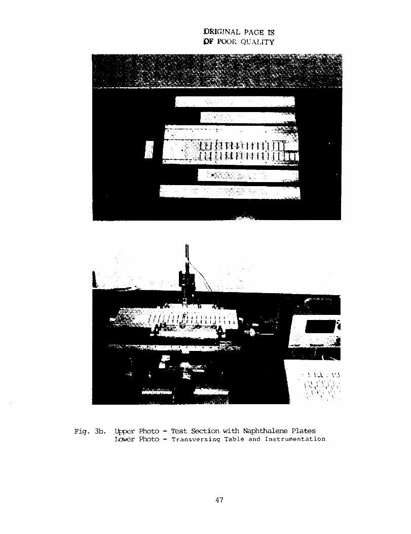
in Figure 3a. The photos of the test section, the traversing table, and
the associated instrumentation are shown in Figure 3b.
Five, 36-gage, copper-constantan thermocouples were used along with
a digital temperature indicator to measure the temperature of the
flowing air and the temperatures at four stations on the naphthalene
surfaces during a test run.
Procedure
After all of the naphthalene plates were prepared under a fume
hood, they were tightly sealed individually in plastic bags to prevent
sublimation. They were then left in the laboratory for six to eight
hours to attain thermal equilibrium. Before a test run, the surface
contours of all the naphthalene plates were measured and recorded. In a
ribbed channel test run, ribs were glued on to the appropriate
naphthalene surfaces. The test section was then assembled and attached
to the rest of the test rig.
To initiate the test run, the blower was switched on to allow air
to flow through the test channel at a predetermined rate. During the
test run, the air temperature, the temperatures at the four stations on
the naphthalene surfaces, the pressure drop across the orifice, the
static pressure upstream of the orifice, and the atmospheric pressure
were recorded periodically. A typical run lasted about 30 minutes. At
the completion of the test run, the contours of the naphthalene surfaces
were measured again. From the corresponding before-run and after-run
9

surface contours, the depth change at each measurement station on the
naphthalene surfaces was calculated.
Separate tests were conducted to determine the .masslosses from the
various naphthalene surfaces due to natural convection while the surface
contours were being measured and while the ribs were being glued on to
the appropriate naphthalene surfaces. It was found that the total mass
loss by natural convection was no more than four percent of the total
mass transfer during any test run. The mass losses due to natural
convection were referred to the Appendix A° In calculating the local
Sherwood numbers, these losses of mass from the various naphthalene
surfaces were taken into account accordingly.
3.2 Data Reduction
The local mass transfer coefficient at any measurementpoint was
determined from the rate of mass transfer per unit surface area and the
local naphthalene vapor density at the measurementpoint, and the local
bulk naphthalene vapor density.
hm= m"ICPw- Pb)" (i)
The rate of mass transfer per unit surface area at the measurementpoint
was evaluated from the density of solid naphthalene, the measuredchange
of elevation at the measurementpoint, and the duration of the test run.
m" = Ps " AZ/At. (2)
The local naphthalene vapor density was calculated from the ideal gas
law in conjunction with the measurednaphthalene surface temperature and
with the vapor pressure-temperature relationship for naphthalene
developed by Sogin (1958).
i0

w = Pw/ (% TwO, <3)
l°gl0 Pw : A - B/T w, (4)
where Rv, A, and B were given by Sogin (1958).
The local bulk naphthalene vapor density was evaluated by the
equation
Pb = M/Q. (5)
The cumulative mass, M, was the total mass which entered the airstream
from the four channel walls between the entrance and the measurement
station over the duration of the test.
Based on the definition of the local Sherwood number,
Sh = hm " D/D : hm " D/(v/Sc), (6)
where the Schmidt number for naphthalene was 2.5, according to Sogin
(1958). The local Sherwood number was normalized by the Sherwood number
for fully developed turbulent flow in a smooth square channel.
Sh /fi
Sho 0.023 Re 0"8 Pr 0-4 (Sc/Pr) 0-4 '(7)
where the correlation of Dittus and Boelter and the heat/mass transfer
analogy, Nu/Sh = (Pr/Sc) 0-4, were used.
Uncertainties in Data Reduction
For a 0.56°C (l°F) variation in the naphthalene surface
temperature, it was found that there was a 6 percent change in the local
naphthalene vapor density, according to equations (3) and (4). In the
present study, the naphthalene surface temperatures were measured at two
ii

stations in each of the two straight sections of the test channel. The
variation of the four temperatures for any test run was never more than
0.28°C (0.5°F). Therefore, the uncertainties in the local vapor density
calculations were relatively small although the surface temperatures at
all the elevation measurement stations were not measured.
It should be noted that the measured naphthalene surface
temperatures were about 0.56°C (l°F) higher than the inlet air
temperature in any test run. If the naphthalene surface temperatures
had not been measured and if the naphthalene surface temperatures had
been assumed to be the same as the inlet air temperature, the calculated
local vapor densities would have been 6 percent too low. As a result,
the local Sherwood numbers would have been 6 percent higher than what
they were supposed to be.
Since the surface contours were measured at discrete points along
one, two, or three lines on the naphthalene surfaces, errors were
introduced into the calculations of the bulk vapor densities when they
were determined from the cumulative mass transferred into the airstreanu
Fortunately, the bulk vapor densities were generally much smaller than
the local naphthalene vapor densities. The maximum values of the former
did not exceed i0 percent of the latter.
The maximum uncertainty in the calculations of (Pw - Pb ) was
estimated to be 6 percent. Other uncertainties in Lhe calculations of
the density of solid naphthalene (_s), of the contour measurement (AZ),
and of the duration of the test run (At) were estimated to be 2, 4, and
3 percent, respectively. By using the uncertainty estimation method of
Kline and McClintock (1953), it was found that the maximum uncertainty
in the calculated local Sherwood numbers was less than 8 percent.
12

4.0 _ _ ANDDISO]SSION
The local mass transfer results are presented in this section as
the axial distributions of a normalized Sherwoodnumber ratio, Sh/Sho,
as given in equation (7). For each set of data, the Sherwood number
ratios along the inner line, the center line, and the outer line (Figure
3a) on the top wall are plotted separately from those along the two
axial lines (inner line and center line) on the inner and outer walls.
Along the axial lines, the Sh/Sho data are not evenly distributed. For
the smoothchannel test runs, there are more data points around the turn
than along the straight sections of the channel. For the ribbed channel
runs, there are manydata points between adjacent ribs on the top wall
to illustrate the axially periodic nature of the Sh/Sho distributions.
A list of mass transfer test runs with all the variable parameters is
presented in Appendix B.
4.1 Experimental Results for the SmoothChannel
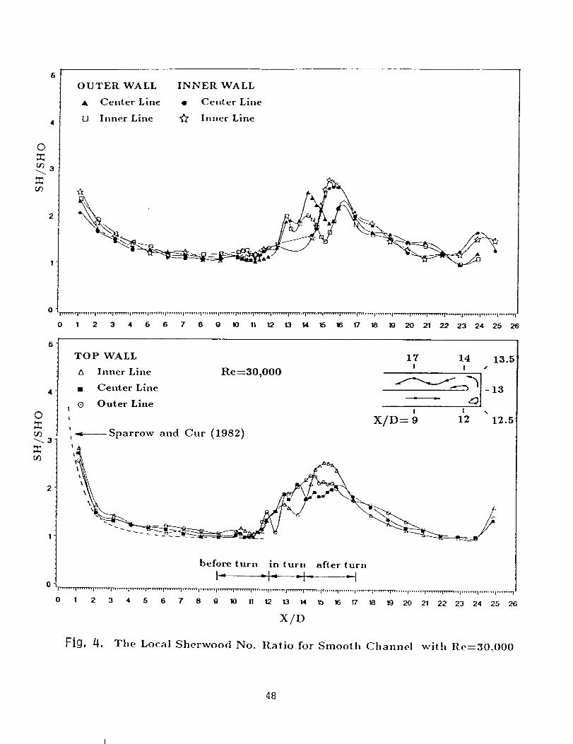
The local Sherwoodnumberratio results for the _rooth channel are
shownin Figures 4, 5, and 6 for the three Reynolds numbersstudied. In
Figure 4, the Sh/ShOdata along the entire test channel are shown, while
in Figures 5 and 6, only the data in the before-turn region, in the turn
region, and in the after-turn region are plotted so that the effect of
the turn on the Sh/Sho can be examined closely. In this paper, the
before-turn and after-turn regions refer to the sections of the test
channel between X/D = 9 and 12, and X/D = 14 and 17 (3Dupstream and 3D
downstreamof the turn), respectively.
Attention is first focused on the Sh/Sho distribution on the top
wall in Figure 4. In the entrance section, the Sherwood number ratio
decreases monotonically with increasing axial distance until it attains
13

the value of one at X/D -= i0. The Sh/Sho distribution compares well
with that for a straight smooth channel of large aspect ratio by Sparrow
and Cur (1982).
Entering the turn region,
increase along the outer line.
the Sh/Sho increases with a rapid
The increase is believed to be the
result of the secondary flow induced by the turn. The dip in the Sh/Sho
distribution along the outer line at X/D = 12.5 indicates that there is
a low mass transfer zone at the outside corner of the turn region. The
outer-line Sh/Sho then increases gradually and reaches a maximumat the
end of the turn (X/D ---14.5). The large Sh/Sho values near the outer
wall at the end of the turn are caused by the flow being forced outward
by the sharp turn.
The low Sherwood number ratios along the inner line at X/D -- 13.5
are due to the flow separation at the tip of the inner wall. The down
turn of the Sh/Sh o distribution along the center line _t X/D--- 14 can
also be attributed to the flow separation. The large values of the
Sh/Sh o at X/D ---15 along the inner line are due to the flow reattachment
and the flow being pushed back toward the inner wall after the turn. In
general, the top-wall Sh/Sh O values in the after-turn region are much
higher than those in the before-turn region.
Leaving the after-turn region, the top-wall Sh/Sh O drops gradually.
The flow becomes almost redeveloped near the end of the second straight
section of the test channel.
Attention is now turned to the Sh/Sh o distributions on the inner
wall and on the outer wall. In the before-turn region, the values of
Sh/Sh o on both the inner and outer walls are about one. In the turn
region, the outer-wall Sh/Sh o increases gradually around the turn. In
14
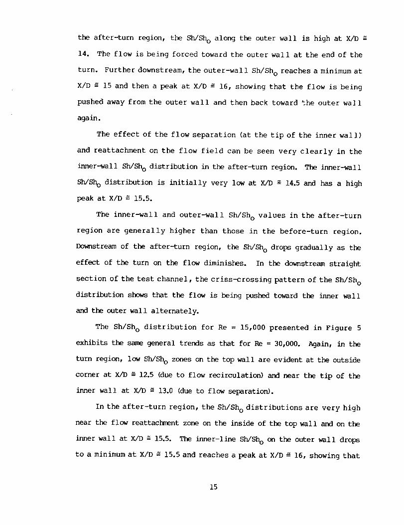
the after-turn region, the Sh/Sho along the outer wall is high at X/D
14. The flow is being forced toward the outer wall at the end of the
turn. Further downstream, the outer-wall Sh/Sho reaches a minimumat
X/D = 15 and then a peak at X/D _ 16, showing that the flow is being
pushed away from the outer wall and then back toward the outer wall
again.
The effect of the flow separation (at the tip of the inner wall)
and reattachment on the flow field can be seen very clearly in the
inner-wall Sh/Sho distribution in the after-turn region. The inner-wall
Sh/ShO distribution is initially very low at X/D _ 14.5 and has a high
peak at X/D = 15.5.
The inner-wall and outer-wall Sh/Sho values in the after-turn
region are generally higher than those in the before-turn region.
Downstreamof the after-turn region, the Sh/Sho drops gradually as the
effect of the turn on the flow diminishes. In the downstream straight
section of the test channel, the criss-crossing pattern of the Sh/Sho
distribution shows that the flow is being pushed toward the inner wall
and the outer wall alternately.
The Sh/Sho distribution for Re = 15,000 presented in Figure 5
exhibits the samegeneral trends as that for Re = 30,000. Again, in the
turn region, low Sh/Sho zones on the top wall are evident at the outside
corner at X/D _ 12.5 (due to flow recirculation) and near the tip of the
inner wall at X/D = 13.0 (due to flow separation).
In the after-turn region, the Sh/Sho distributions are very high
near the flow reattac_nent zone on the inside of the top wall and on the
inner wall at X/D = 15.5. The inner-line Sh/Sho on the outer wall drops
to a minimum at X/D _ 15.5 and reaches a peak at X/D _ 16, showing that
15

the flow may be forced away from the outer wall and the inner wall
alternately in the after-turn region, as in the case of Re = 30,000.
The Sh/Sho distribution for Re = 60,000 (Figure 6) is only slightly
different from those for Re = 30,000 and 15,000. Just before entering
the turn region (X/D -- 11.5), the inner-wall Sh/Sh O increases while the
outer-wall Sh/Sh o decreases to below one. The flow being forced inward
due to the turn is more evident in this case than in the two previous
cases.
The recirculation zone at the outside corner of the turn at X/D -=
12.5 as well as the flow reattach, ent zone on the inner wall and on the
inside of the top wall at X/D ---15.5 can be identified very easily. In
the turn region, the inner-line Sh/Sh o on the top wall remains quite
constant. Otherwise, the Sh/Sh O distribution for Re = 60,000 is similar
to those for the two low Reynolds numbers studied.
4.2 Experimental Results for the Rib-Roughened Channel
4.2.1 Local Mass Transfer Data
The experimental results for the rib-roughened channel with e/D =
0.063, P/e = i0, and e = 90 ° are shown in Figures 7, 8, and 9. Firstly,
the Sh/Sh o distribution for Re = 60,000 shown in Figure 7 will be
examined. In the entrance section of the test channel, the axial Sh/Sh o
distribution on the top wall decreases with increasing distance, and
settles into a periodic pattern with a small spanwise variation, just
before entering the sharp turn. In the periodic region, the maximum
Sh/Sh o value between adjacent ribs is approximately equal to 3. The
axial location where the value of Sh/Sh o is maximum (due to flow
reattachnent) is about 2 to 3 times the rib-height downs[ream of a rib.
At X/D -= ii, the top-wall Sh/Sh o increases with a faster increase along
16

the outer-line than along the inner-line as the flow begins to turn
inward.
In the turn region, the top-wall Sh/Sho is relatively low since
there is no rib in the region. In the after-turn region, the top-wall
Sh/Sho distribution is generally higher than that in the before-turn
region. There is an increase in the Sh/Sho in the spanwise direction
toward the outer wall. Further downstreamof the turn, the peak between
adjacent ribs in the Sh/Sho distribution decreases gradually and the
spanwise variation becomes smaller. The Sh/Sh o becomes periodic again
near the end of the second straight section of the channel.
In the before-turn region, the Sh/Sh o distribution on the inner
wall is about the same as that on the outer wall with the inner-line
Sh/Sh o values on each wall slightly higher than the corresponding
center-line Sh/Sh o values (due to the proximity of the ribs on the top
wall to the inner line on each wall). The outer-wall Sherwood number
ratios in the turn region are generally higher than those in the before-
turn region.
After the turn, the side-wall Sherwood number ratios remain as high
as those in the turn region, with the values on the inner-wall slightly
higher than those on the outer wall. The initial low values of the
inner-wall Sh/Sh o at X/D ---14.5are due to the flow separation at the tip
of the inner wall. The flow reattaches at X/D ---15, resulting in the
peak in the inner-wall Sh/Sh o distribution. In the downstream straight
section of the channel, the inner-wall and the outer-wall distributions
cross several times more. It appears that the flow is being pushed
toward the inner wall and the outer wall alternately as a result of the
turn.
17
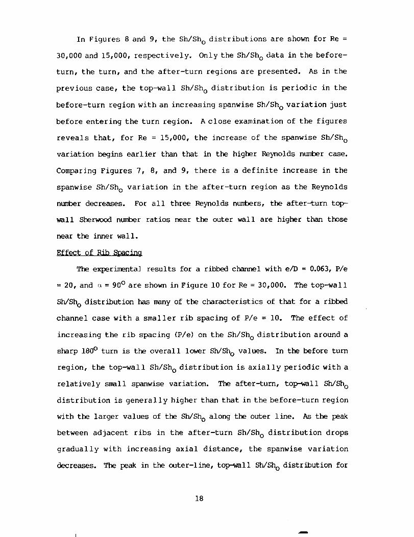
In Figures 8 and 9, the Sh/ShOdistributions are shown for Re =
30,000 and 15,000, respectively. Only the Sh/Sho data in the before-
turn, the turn, and the after-turn regions are presented. As in the
previous case, the top-wall Sh/ShOdistribution is periodic in the
before-turn region with an increasing spanwise Sh/Sho variation just
before entering the turn region. A close examination of the figures
reveals that, for Re = 15,000, the increase of the spanwise Sh/Sho
variation begins earlier than that in the higher Reynolds numbercase.
Comparing Figures 7, 8, and 9, there is a definite increase in the
spanwise Sh/Sho variation in the after-turn region as the Reynolds
numberdecreases. For all three Reynolds numbers, the after_turn top-
wall Sherwoodnumber ratios near the outer wall are higher than those
near the inner wall.
Effect of Rib _Spacing
The experimental results for a ribbed channel with e/D = 0.063, P/e
= 20, and _ = 90 ° are shown in Figure i0 for Re = 30,000. The top-wall
Sh/Sh o distribution has many of the characteristics of that for a ribbed
channel case with a smaller rib spacing of P/e = 10. The effect of
increasing the rib spacing (P/e) on the Sh/Sh o distribution around a
sharp 180 ° turn is the overall lower Sh/Sh o values. In the before turn
region, the top-wall Sh/Sh o distribution is axially periodic with a
relatively small spanwise variation. The after-turn, top-wall Sh/Sh o
distribution is generally higher than that in the before-turn region
with the larger values of the Sh/Sh o along the outer line. As the peak
between adjacent ribs in the after-turn Sh/Sh o distribution drops
gradually with increasing axial distance, the spanwise variation
decreases. The peak in the outer-line, top-wall Sh/Sh O distribution for
18

P/e = 20 drops in the streamwise direction slightly faster than that for
P/e = ]0.
Effect of Rib Height
The effect of the height of the ribs on the heat transfer around a
sharp turn is studied by examining Figures 8 and ii, in which the Sh/Sh o
distributions for e/D = 0.063 and 0.094, respectively, are shown. The
top-wall Sh/Sh O distribution for e/D = 0.094 is higher than that for e/D
= 0.063 around the sharp turn. In both cases, the peaks in the top-wall
Sh/Sh o distributions in the after-turn region drop with increasing axial
distance at about the same rate.
The spanwise variation of the after-turn top-wall Sh/Sh o for ribs
with a large e/D is smaller than that for ribs with a small e/D.
On the inner and outer walls, the Sh/Sh o distributions for e/D =
0.094 are again higher than those for e/D = 0.063 around the turn. In
the after-turn region, the inner-wall and outer-wall Sherwood number
ratios for e/D = 0.094 stay about constant with the inner-wall Sh/Sh o
values higher than the outer-wall values. There is no crossing of the
inner-wall and the outer wall Sh/Sh o distributions in the e/D = 0.094
case. It appears that the larger ribs keep the flow from being
deflected laterally downstream of the turn.
Effect of Rib Angle on Local Sherwood Number Ratio
The distributions of the ribbed-wall Sherwood number ratio along
three axial lines for _ = 90 ° and for Re = 30,000 are shown in Figure
12. The periodic nature of the distributions in the entrance duct is
evident. The Sherwood number ratios attain their maximum values at the
points of flow reattachment, which occur slightly upstream of the mid
points between adjacent ribs. The variations of the Sherwood number
19
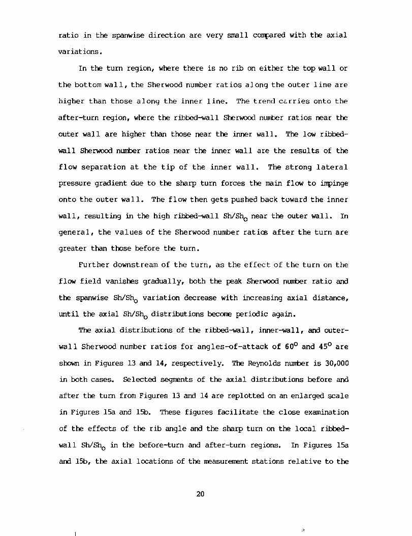
ratio in the spanwise direction are very small co_pared with the axial
variations.
In the turn region, where there is no rib on either the top wall or
the bottom wall, the Sherwood number ratios along the outer line are
higher than those along the inner line. The trend carries onto the
after-turn region, where the ribbed-wall Sherwoodnumberratios near the
outer wall are higher than those near the inner wall. The low ribbed-
wall Sherwoodnumber ratios near the inner wall are the results of the
flow separation at the tip of the inner wall. The strong lateral
pressure gradient due to the sharp turn forces the main flow to impinge
onto the outer wall. The flow then gets pushed back toward the inner
wall, resulting in the high ribbed-wall Sh/ShO near the outer wall. In
general, the values of the Sherwood number ratios after the turn are
greater than those before the turn.
Further downstream of the turn, as the effect of the turn on the
flow field vanishes gradually, both the peak Sherwoodnumber ratio and
the spanwise Sh/ShO variation decrease with increasing axial distance,
until the axial Sh/Sho distributions becomeperiodic again.
The axial distributions of the ribbed-wall, inner-wall, and outer-
wall Sherwood number ratios for angles-of-attack of 60° and 45° are
shownin Figures 13 and 14, respectively. The Reynolds number is 30,000
in both cases. Selected segments of the axial distributions before and
after the turn from Figures 13 and 14 are replotted on an enlarged scale
in Figures 15a and 15b. These figures facilitate the close examination
of the effects of the rib angle and the sharp turn on the local ribbed-
wall Sh/Sho in the before-turn and after-turn regions. In Figures 15a
and 15b, the axial locations of the measurementstations relative to the
2O

ribs are also illustrated.
For _ = 60° , the magnitude of the variations of the before-turn
top-wall Sh/Sho in the spanwise direction is comparable to those of the
axial periodic Sh/Sho distributions. The values of the before-turn
Sh/ShO along the outer line are always greater than the correspor_ing
values along the inner line. These lateral variations of the ribbed-
wall Sh/Sho in the before-turn region are due to the secondary flow
along the rib axes toward the inner wall.
In the turn, the values of Sh/Sho are lower than those before the
turn with Sh/Sho along the outer line generally higher than those along
the center line and the inner line.
After the turn, the peak Sherwood number ratios along the outer
line decrease significantly from the before-turn values, meanwhile, the
decreases (from the before-turn values) of the peak Sh/Sho along the
center line and along the inner line are successively lower than those
along the outer line. The spanwise variations of Sh/ShO are relatively
small after the turn. This maybe caused by the complicated interaction
between the main flow, which is forced toward the inner wall due to the
turn (as described earlier), and the secondary flow along the rib axes
toward the outer wall.
For e = 45°, the top-wall Sh/Sho distributions before the turn are
similar to those for _ = 60O. Again, the Sherwoodnumber ratios along
the outer line are higher than those along the center line, which, in
turn, are higher than those along the inner line. The Sherwoodnumber
ratio is relatively uniform in the turn. The after-turn values of
Sh/Sho are about the sameas those in the before-turn region.
Attention will now be turned to the top of Figures 13 and 14, where
21

the axial inner-wall and the outer-wall Sherwoodnumber distributions
are given. For e = 60° , the spanwise variations of the before-turn
Sh/Sho on the inner (divider) wall are much larger than those on the
outer wall. The before-turn Sherwoodnumberratios along the inner line
on the inner wall are muchgreater than those along the center line on
the inner wall, while on the outer wall, the center-line Sh/Sho were
only slightly higher than the inner-line Sh/Sho. The secondary flow
created by the oblique ribs impinges onto the inner wall, resulting in
the high Sh/Sho on the inner wall near the ribbed walls. For _ = 45° ,
the before-turn Sh/Sho exhibit the sametrends except that the spanwise
Sh/Sho variations on the inner wall are not as large as those for _ =
60°.
After the turn, the inner-wall Sh/ShO for both _ = 60° and _ = 45°
are large compared to the corresponding outer-wall Sh/Sho. The high
Sh/Sho on the inner wall is believed to be caused by flow reattac_ent
along with the main flow, which is being forced toward the inner wall
due to the turn. On the outer wall, the after-turn Sh/Sho along the
inner line are higher than those along the center line for e = 60° .
However, the reverse is true in the case of e = 45° .
Effect of Reynolds Number
The effect of the Reynolds number on the local Sherwood number will
now be examined. Experimental data for _ = 60 ° and 45 ° and for Re =
15,000 and 60,000 are presented in Figures 16 through 19.
Attention is focused first on Figures 16 and 17, along with Figure
13. The top-wall Sherwood number ratios in all three cases are very
similar. The spanwise top-wall Sh/Sh O variations decrease with
increasing Reynolds number. Before the turn, there are much larger
22
spanwise Sh/Sho variations on the inner wall than on the outer wall for
all Reynolds numbers. However, the differences are less evident in the
case of Re = 15,000. After the turn, the inner-wall Sherwood number
ratios are always higher t_kan the corresponding outer-wall values and
the differences are smaller at higher Reynolds numbers.
Comparing Figures 18 and 19 with Figure 14, it can be seen that the
spanwise variations of the before-turn, top-wall Sh/Sh o are again very
large at low Reynolds numbers. The differences between the before-turn
Sh/Sh o variations on the inner wall and those on the outer wall are most
pronounced at Re = 15,000.
In general, the flow Reynolds number has only a modest effect on
the local S_rwood number ratio.
4.2.2 Average Mass Transfer Data and Correlations
Results for Smooth Channel and for Transverse Ribs (cx = 90°)
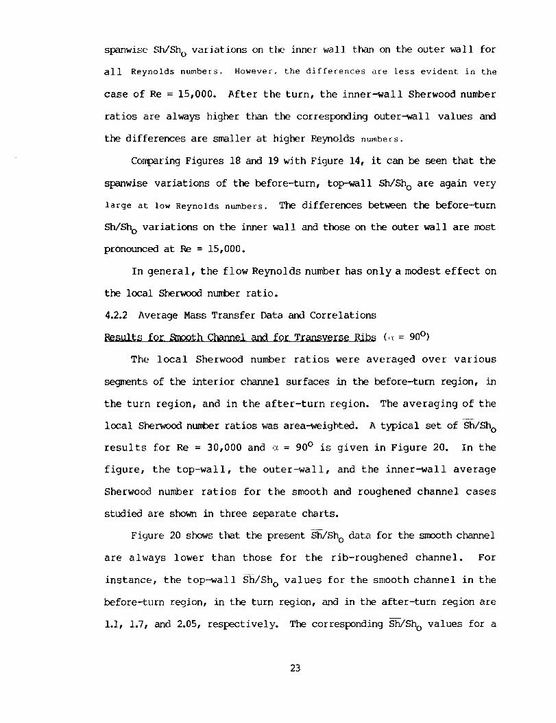
The local Sherwood number ratios were averaged over various
segnents of the interior channel surfaces in the before-turn region, in
the turn region, and in the after-turn region. The averaging of the
local Sherwood number ratios was area-weighted. A typical set of Sh/Sh O
results for Re = 30,000 and _ = 90 ° is given in Figure 20. In the
figure, the top-wall, the outer-wall, and the inner-wall average
Sherwood number ratios for the smooth and roughened channel cases
studied are shown in three separate charts.
Figure 20 shows tlkat the present Sh/Sh o data for the smooth channel
are always lower than those for the rib-roughened channel. For
instance, the top-wall _/Sh o values for the smooth channel in the
before-turn region, in the turn region, and in the after-turn region are
i.i, 1.7, and 2.05, respectively. The corresponding S-h/ShO values for a
23

typical roughened channel with P/e = I0, e/D = 0.063, and e = 90° are
2.6, 2.55, and 3.5. Increasing the rib height results in a higher
S-h/Sho around the turn due to the higher turbulence level in the flow
for the larger rib case. However, increasing the rib pitch lowers the
Sh/Sho around the turn because of the longer boundary layer between
adjacent ribs downstreamof the reattachment zone.
The after-turn _/Sh O values are always higher than the
corresponding before-turn values as a result of the sharp turn. For the
smooth channel, the top-wal i S-_/Sho in the turn region is more than
fifty percent higher than that in the before-turn region. However, for
the roughened channel cases, the top-wall Sh/ShO values in the turn
region are slightly lower than the respective before-turn S--_ShO values
because there is no rib on the top-wall in the turn region.
In all of the cases studied, the values of the outer-wall Sh/Sho in
the turn region are only slightly different from the corresponding
after-turn values.
The S-h/Sho data for both the smooth and roughened channels were
found to be correlated well by the following equation:
S-h/Sho = a Reb [(e/D)/0.063] m . [(P/e)/10] n, (8)
with the numerical values of a, b, m, and n listed in Table 2. Equation
(8) correlates all of the Sh/Sh o data of the present investigation to
within + 6 percent. Readers should be cautioned that equation (8)
applies only to a smooth channel or a ribbed channel with a rib angle-
of-attack of 90 °. Correlations for other angle-of-attack cases can be
found in equation (9). In Figures 21a and 21b, the present top-wall
Sh/Sh O data in the before-turn and the after-turn regions for both the
24

smooth and roughened channels are plotted against the flow Reynolds
numberalong with the correlation of equation (8).
P_sults for Angled Ribs (_ = 90° , 60° , and 45° )
For all the cases studied, the local Sherwood number ratios for
individual segments of the channel walls before the turn, in the turn,
and after the turn were averaged. Typical average Sherwood number
ratios, those for Re = 30,000, are shown in Figures 22a and 22b. In
Figure 22a, the average Sherwood number ratios (Sh/Sh O) are plotted as
functions of the rib angle. Before the turn, the top-wall Sh/Sh o are
much greater t_n the outer-wall Sh/Sh o and the inner-wall Sh/Sh o for
all three angles-of-attack of 90°, 60°, and 45°. The top-wall Sh/Sho,
the outer-wall Sh/Sho, and the inner-wall Sh/Sh o for e = 60 ° are all
higher than their counterparts for _ = 90° and _ = 45°.
After the turn, the inner-wall Sh/Sh o are higher than the outer-
wall Sh/Sh o for all three rib angles. Also, the top-wall Sh/Sh o for (_=
60 ° decreases significantly after the turn from its before-turn value
while those for ¢_ = 90 ° and 45 ° increase after the turn from their
corresponding before-turn values. These trends are also evident in
Figure 22b, where the Sh/Sh O results are replotted to show the effect of
the sharp 180 ° turn on the average S_rwood number ratios for the three
rib angles-of-attack studied.
The average Sherwood nuM3er ratios for the various segments of the
c_nnel walls were found to be correlated well with the Reynolds number
and tl_ rib angle by the following equation
S--h/Sho = a Re b (<_/90°) c , (9)
where a, b, and c are constant coefficients. The numerical values of
25

these coefficients are listed in Table 3. Equation (9) with
coefficients from Table 3 correlate the experimental data of the present
study to within + 6 percent. It should be noted that equation (9)
applies to e/D = 0.063 and P/e = I0 only. Correlations for the cases of
other e/D and P/e ratios can be found in equation (8).
Figure 23a shows (Sh/Sho)(90°/_)c as a function of the flow
Reynolds number. The experimental data points shown in the figure are
the top-wall Sh/Sh o obtained in the present study. The figure shows
that the present experimental before-turn and after-turn results are
_ell represented by the equations.
The Sherwood number ratios for all of the surfaces in and around
the 180 ° turn were averaged. The overall average S_rwood number ratios
(Sh/Sh o) for the three rib angles studied are plotted versus the flow
Reynolds number in Figure 23b. The overall Sherwood number ratio is
independent of the rib angle but decreases slightly with increasing
Reynolds number. It was found that the following equation
_h/Sh o = 7.0 Re -0"I (i0)
correlates the data to within + 4 percent.
4.2.3 Comparison with Heat Transfer Data
Results for Smooth Channel and for Transverse Ribs (_ = 90 °)
The results of the present study will now be compared with
published heat transfer data for smooth and roughened c_nnnels with _ =
90 °. The present smooth channel data are presented in Figure 24a along
with the heat transfer data for a smooth two-pass channel of an aspect
ratio of 0.4 reported by Metzger and Sahm (1985). In Figure 24a, the
present overall Sherwood number ratio in the before-turn, the turn, or
26

the after-turn region, _/Sho, is the area-weighted average of the
Sh/Sho values on the top and side walls in the respective region. The
heat transfer data are based on the Nusse]t number-Reynolds number
correlations in regions 2, 3, and 4 given by Metzger and Sahm(1985).
The Nusselt numbersare converted to the corresponding Sherwoodnumbers
by Sh = (Sc/Pr)0"4 Nu.
Both the present masstransfer dat_Jand the published heat transfer
data show that, for all three Reynolds numbers, the average Sherwood
number ratios in the after-turn region and in the turn region are
successively higher than those iD the before-turn region. In addition,
both the present data and those of Metzger and Sahm(1985) decrease
slightly with increasing Reynolds number.
For the typical case of Pe = 30,000, the present mass transfer data
in the before-turn region and in the turn region are about 4 and 12
percent higher than the corresponding heat transfer data, while the
present Sh/Sho in the after turn region is about 9 percent lower.
Considering the differences in the channel aspect ratios and in the
channel surfaces over which the data are averaged in the two studies,
the agreement between the present data and those by Metzger and Sahm
(1985) is very good.
In Figure 24b, the present ribbed channel data are compared with
the heat transfer data by Han et al. (1985, 1986). The heat transfer
data are for the fully developed flow of air in a uniformly heated,
straight, square channel with two opposite ribbed walls, and with the
same values of e/D, P/e, and Re as those of the present study. The
fully developed Nusselt numbers on the ribbed walls are converted to
their corresponding Sherwoodnumbers. They are then plotted along with
27

the before-turn, top-wall Sh/Sho data of the present study for the three
Reynolds numbers of 15,000, 30,000, and 60,000. Figure 24b shows that
the present masstransfer data are slightly higher ¢Dyup to i0 percent)
than the heat transfer data. This maybe due to the effect of the turn
on the top-wall S-_/Sho at the end of the before-turn region.
Results for Angled Ribs (_ = 90 °, 60O, and 45 °)
In Figure 25, the averages of t_ before-turn ribbed-wall Sherwood
numbers for all the cases studied were com_red with the fully developed
average heat transfer data reported by Han et al. (1985, 1986). The
average heat transfer data are those for the fully developed flow of air
in a uniformly heated, straight, square channel with two opposite ribbed
walls, and with the same values of e/D, P/e, e, and Re as those of the
present study. The Nusselt numbers from the heat transfer studies were
converted to their corresix)nding S_erwood numbers.
It can be seen from Figure 25 that the present mass transfer
results compared very well with the publ ished heat transfer data in most
cases. The deviations between the heat transfer and mass transfer data
are less than i0 percent, except for the case of _ = 45 ° and Re =
60,000, the deviation of which is 14 percent. The good agreement
between the heat and mass transfer data reaffirms that the naphthalene
sublimation technique is a reliable tool for the determination of highly
localized distributions of the heat transfer coefficient in complicated
channel flows, such as those encountered in the present study.
The published heat transfer data in NASA CR-4015 (Han 1986)
shows an incorrect rib orientation for the square duct. A
published errata gives the correct orientation.
28
5.0 P_E_ DROP
5.1 Test Section and Data Analysis
A schematic diagram of the test section for pressure drop/friction
factor experiments is shown in Figure 26. The flow geometry of this
apparatus models situations that exist in actual turbine engine air-
foils. The internal geon_try of the test section and the construction
were very similar to that of the mass transfer test section described
earlier. The only difference was of the n_terial used for construction.
In this case, Plexiglas was used instead of aluminum.
To measure the pressure drop, twenty (20) pressure taps (i/32-in)
in all were drilled in the channel walls at locations shown in Figure
26. Fifteen (]5) out of twenty (20) pressure taps were along the outer
wall of the test c_xtnel with eight (8) taps before the turn and seven
(7) taps after the turn region. The remaining five (5) taps were provided
on the top wall with two (2) taps each before and after the turn and one
(i) in the turn region. The pressure taps number 3, 7, ii, and 15 were
thoughtfully used to take into account the difference in pressure drop
data at t_ top wall and the side wall (if any). For the calculations
of the pressure drop and friction factor, the average values were
considered at these four cross-sectional locations.
For the rough channe] tests, the brass ribs were placed and glued
onto the top and the bottom walls in the pre-determined fashion as was
done in the case of mass transfer test runs.
The pressure drop across the channel route was measured by an
inclined or a U-tube manometer. During the experiments, it was seen
that the magnitude of the pressure drop was almost the same on the
smooth side and the ribbed side walls. Therefore, the pressure drop and
29

the friction factor calculated were on the basis of the average values.
The average friction factor of the present investigation was based on
the adiabatic conditions (non-heating test runs).
The Blausius equation,
f(FD) = 0.079 Re-0-25 (ii)
was used to provide reference values of the friction factor to compare
the smooth channel fully-developed results in the two straight sections
of the present test channel.
The following equation was used to calculate the friction factors
in the fully-developed before and after turn regions of the channel, fbt
and fat"
APf = (12)
4(L/D) (G2/2F_c)
where,
L = length of the test channel corresponding to the pressure drop, Ap,
L = 6.25 inches for before-turn fully-developed region [Tap 3 to 7], and
L = 5.00 inches for after-turn fully-developed region [Tap 14 to 16].
The loss factor due to sudden contraction at the entrance, Kc, and
the loss factor for the turn region, Kt, was calculated by using the
following relation;
AP
Kc (or K t) = (13)
pV2/2gc
The pressure drop for the entrance loss factor, Kc,
corresponded to 35/16 inches of channel entrance length (Tap 3) and for
3O

the turn loss factor, Kt, corresponded to 7 inches of channel
length (Tap 7 to 14).
For a better comparison, the pressure drop values were non-
dimensional ised by the dynamic pressure (I/2pV 2) and the plots were
drawn between the non-dimensional pressure drop and distance, X/D.
5.2 Results and Discussion
Pressure Dist ribut ion
The non-dimensional pressure drop [(P - Patm)/(i/2)pV 2] results are
plotted against non-dimensional axial distance [X/D]. Each channel
geometry investigated was tested at six flow rates, covering Reynolds
numbers from i0,000 to 60,000. A list of pressure drop test runs with
all the variable parameters is presented in Appendix C. Figures 27-32
show the plots with different channel/rib geometries in the same order
as the list given in Appendix c.
Pressure distributions in all the cases show almost the same trend,
that is, the non-dimensional pressure drop increasing with decreasing
Reynolds number. The pressure drops _fap i, X/D = 0.31) sharply at the
sudden contraction entrance of the channel to almost the same value in
all the cases. The effect of Reynolds number is also very minimal. The
pressure then rises by the next tap location (X/D = 2.19, Tap 2) and
then drops in a linear fashion till tap 7 (X/D = 10.94). The results
show that from X/D = 4.69 (Tap 3) to X/D = 10.94 (Tap 7) can be treated
as the fully-developed flow region before the turn. The pressure then
rises slightly in the vicinity of the upstream corner of the turn (X/D =
11.56, Tap 8). A rapid drop in pressure has been seen in the turn
region (X/D = Ii.56, Tap 8 to X/D = 14.44, Tap i0), and just after the
turn in the downstream section of the channel (X/D = 15.06, Tap Ii).
31

The pressure then increases again slightly (except for cases with higher
size rib, e/D = 0.094), as shown in Figure (32). A linear pressure drop
towards the fully-developed region of the downstream section (between
X/D = 18.8, Tap 14 and X/D = 23.8, Tap 16) is clearly visible.
Examination of the individual pressure distributions for each test
reveals that their trends are highly independent of the Reynolds number
and the normalized distributions are virtually identical over the entire
range of Reynolds number for a given channel geometry.
Figures 33-35 represent the effect of the rib geometry on non-
dimensional pressure drop distribution for Re = i0,000, Re = 30,000, and
Re = 60,000, respectively. Again, the results are almost independent of
the Reynolds number. But on looking at these plots individually, it is
very clear that the pressure drop in the case of the smooth channel is lowest,
maximum pressure drop is attained in the case of the channel with higher
rib size (e/D = 0.094). In order, the results with higher pitch (P/e =
20), angle-of-attack (<_) = 45 ° , and angle-of-attack (e) = 60 ° show
an increase in pressure drop, but remain in between the smooth channel
and with e/D = 0.094 cases.
Friction Factor and Loss Coefficients
On the basis of the normalized pressure distribution results and to
cover the entire test channel under present investigation, the channel
was divided into four regions, namely, the entrance region (X/D = 0 to
4.69, Tap 3), the fully-developed before-turn region (X/D = 4.69, Tap 3
to 10.94, Tap 7), the turn region (X/D = 10.94, Tap 7 to 18.8, Tap 14),
and the fully-developed after-turn region (X/D = 18.8, Tap 14 to 23.8,
Tap 16).
The plots for average fully-developed friction factors, f%t and fat
32

vs Reynolds number for the different rib and channel geometries are
shown in Figures 36 and 37. The loss coefficients, Kc and Kt, for the
entrance and the turn regions respectively, are plotted against Reynolds
number in Figures 38 and 39.
In Figure 36 for fbt' the friction factor for the smooth channel case
differs by 6% from the Blausius equation (ii). For e = 90 ° and e = 60°,
the friction factor approaches an approximately constant value as the
Reynolds number increases, while the friction factor is maximum with
higher size rib and minimum with higher rib spacing. The friction
factor with e = 60 ° is about 45% higher than that with _ = 90 ° . Also
the friction factor with _ = 45° is less than that with e = 90°, but not
by much.
The trend of Figure 37 for fat looks the same as that of fbt in Figure
36, except that the variation is not very smooth and also the values
with _ = 45 ° are lower than that with P/e = 20 at some locations. For the
smooth channel case, the friction factor is approximately 100% higher
than the values calculated by equation (ii). It is interesting to note
that the average friction factor for the fully-developed after-turn
region is higher than the corresponding fully-developed before-turn
region, except in cases with _ = 60° and _ = 45 ° , in which fat is lower
than their respective values of fbt"
The loss coefficient in the entrance section of the channel, Kc,
decreases with increasing Reynolds number, as shown in Figure 38.
Figure 39 shows the loss coefficient, Kt, against Reynolds number for
the turn region. It decreases with increasing Reynolds number. The
effect of rib geometry on these two loss coefficients are identical as
far as the trend and the overall range is concerned. It is noted that,
33
for _ = 90° and P/e = i0, Kc is lower than with sameP/e but with _ =
60° and _ = 45°. However, Kt for _ = 90° is higher than that for _ = 60°
and 45° for the sameP/e = i0. Both loss coefficients remain maximum
with higher rib size in all cases.
For all the cases investigated, the values of all the four friction
factors are tabulated in Table 4.
The two fully-developed friction factors, fbt and fat' and the two
loss coefficients, Kc and Kt were correlated by one single equation of
the following form:
(or K) = a (Re)b ((P/e)/10) c ((e/D)/0.063) m (e/90°) n (14)
where the coefficients, a, b, c, m, and n, are given in Table 5. The
deviations in equation (]4) from the test data are _+ 7%, __ 10% (8% for
95% data points), + 5.5%, and + 6.6%, respectively, for {bt' fat' Kc and
Kt •
34

6.0 (]0N[_0SI_ AND _OHS
The detailed mass transfer distributions around the sharp 180 °
turns in a smooth channel and in a rib-roughened channel have been
studied. The following conclusions can be drawn:
A. Smooth Channel and Transverse Ribs:
i. For the smooth channel, the heat/mass transfer around the turn is
influenced by the flow separation at the tip of the divider (inner)
wall and the secondary flow induced by the centrifugal force at the
turn. The heat/mass transfer after the turn is higher than that
before the turn. The heat/mass transfer in the turn is also high
compared with that before the turn except at the first outside
corner of the turn.
2. For the rib-roughened channel, the heat/mass transfer around the
turn is influenced not only by the flow separation and the
secondary flow at the turn, but also by the presence of repeated
ribs on the top and bottom walls. The heat/mass transfer
coefficients on the smooth side walls and on the rib-roughened top
and bottom walls around the turn are larger than the corresponding
coefficients for the smooth channel. The axially periodic
distribution of the top-wall heat/mass transfer coefficient after
the turn is higher than that before the turn with a more noticeable
spanwise variation. The inner-wall and outer-wall heat/mass
transfer coefficients after the turn are higher than the respective
before-turn coefficients.
3. For the range of Reynolds number studied, the average Sherwood
number ratios around the sharp turns in the smooth and rib-
roughened channels decrease slightly with increasing Reynolds
35

number. For the ribbed channel, the spanwise variation of the top-
wall Sherwoodnumberratio in the after-turn region increases with
decreasing Reynolds number.
4. The heat/mass transfer around the turn in the ribbed channel
decreases with increasing rib spacing and increases _ith increasing
rib height.
5. The average Sherwood number ratios for individual wall segments
around the turns in the smooth and ribbed channels can be
correlated by equation (8) to within + 6 percent.
6. The published heat transfer results for straight rib-roughened
channels can be applied to the design of the straight section
before the first sharp turn in a multipass ribbed cooling passage
in a turbine blade.
B.
i. Before the turn, the axial distributions of the ribbed-wall
Sherwood number are periodic for all three rib angles-of-attack
studied. The local ribbed-wall Sherwood numbers for _ = 60 ° and
45 ° near the outer wall are higher than those near the inner wall
due to the secondary flow along the rib axes. The spanwise
Sherwood number variations decrease as the Reynolds number
increases. The spanwise variations of the local ribbed-wall
Sherwood number for e = 90° are very small.
2. After the turn, the ribbed-wall Sherwood numbers near the outer
wall are higher than those near the inner wall for all three rib
angles studied. For _ = 60 ° and 45 ° , the spanwise variations of
the ribbed-wall Sherwood numbers after the turn are smaller than
those before the turn.
36
.
.
.
.
1
C.
i.
o
1
Before the turn, the average ribbed-wall Sherwood number for _ =
60° is higher than that for _ = 45°, which, in turn, is higher than
that for _ = 90 °• However, after the turn, the average ribbed-
wal i Sherwood number for e = 90 ° is higher than those for _ = 45 °
and 60 ° .
For any rib angle-of-attack, the average inner-wall Sherwood number
after the turn is always higher than both the average inner-wall
Sherwood ntm_er before the turn and the average outer-wall Sherwood
number after the turn.
The average Sherwood ntm_er ratios for individual channel surfaces
can be correlated with equations in the form of Sh/Sh o = a Reb
(_190o)c.
The overall average Sherwood number ratio in the region around the
sharp turn is independent of the rib angle, but decreases slightly
as the Reynolds number increases.
The t_o fully-developed friction factors (f-btand Fat), and the two
loss coefficients 0Kc and Kt) can be correlated by equation (14).
Recommendat ions:
Use naphthalene-coated ribs, instead of using metallic ribs, to
study the local heat/mass transfer coefficients in a two-pass rib-
roughened channel.
Study the effect of the channel aspect ratio on the local heat/mass
transfer coefficients in two-pass ribbed channels.
Study the three-pass ribbed channels.
37

7.0
Han, J.C., 1984, "Heat Transfer and Friction in Channels with Two
Opposite Rib-RoughenedWalls," ASME Journal of Heat Transfer. Vol. 106,
pp. 774-781.
Han, J.C., Park, J.S., and Lei, C.K., 1984, "Heat Transfer and
Pressure Drop in Blade Cooling Channels with Turbulence Promoters," NASA
CR-3837.
Han, J.C., Park, J.S., and Lei, C.K., 1985, "Heat Transfer Enhancement
in Channels with Turbulence PronDters," ASME Journal of Engineering_ for
Gas Turbines and Power. Vol. 107, pp. 628-635.
Han, J.C., Park, J.S., and Ibrahim, M.Y., 1986, "Measurement of Heat
Transfer and Pressure Drop in Rectangular Channels with Turbulence
Promoters," NASA CR-4015 or USAAVSOOM-TR-86-C-25.
Boyle, R.J., 1984, "Heat Transfer in Serpentine Passages with
Turbulence Promoters," ASME Paper No. 84-HT-24.
Sogin, H.H., 1958, "Sublimation from Disks to Air Streams Flowing
Normal to Their Surfaces," Trans. of ASME. Vol. 80, pp. 61-69.
Kline, SJ., and McClintock, F.A., 1953, "Describing Uncertainties in
Single-Sample Experiments," Mechanical Engineering. Vol. 75, pp. 3-8.
Sparrow, E.M., and Cur, N., 1982, "Turbulent Heat Transfer in a
Symmetrically or Asy_netrically Heated Flat Rectangular Duct with Flow
Separation at Inlet," J. of Heat Transfer. Vol. 104, pp. 82-89.
Metzger, D.E., and Sahm, M/(., 1985, "Heat Transfer Around Sharp 180
Degree Turns in Smooth Rectangular Channels," ASME Paper No. 85-GT-122.
38

TABLE i. LIST OF HEA]/MASS ]RANSFEIR [I::$I RUNS
CHANNEL
SMOOTH
ROUGH
ROUGH
ROUGH
ROUGH
ROUGH
Re P/e e/D (_
15,000
30,000
60,000
15,000
30,000
60,000
15,000
30,000
60,000
15,000
30,000
60,000
30,000
10
10
10
10
10
10
10
10
10
2O
0.063
0.063
0.063
0.063
0.063
0.063
0.063
0.063
0.063
90 °
90 °
90 °
60 °
60 °
60 °
0.063
45 °
45 °
45 °
30,000 10 0.094
90 °
90 °
Re : REYNOLDS NUMBER
P/e • PITCH-TO-RIB HEIGHT RATIO
e/D • RIB HEIGHT-TO-HYDRAULIC DIAMETER RATIO
o_ : RIB ANGLE-OF-ATTACK
39

Table 2. Numerical Values of the (__fficients a, b, m, emd n
in Equation (8)
Region Surface a b m n
before turn,smooth channel
in turn,
smooth channel
after turn,smooth channel
before turn,ribbed channel
in turn,ribbed channel
after turn,
ribbed channel
top wall 2.02outer wall 2.10
inner wall 2.08
top wall 3.21outer wall 3.23
top wall 3.84outer wall 3.45
inner wall 4.07
top wall 7.2outer wall 4.6
inner wall 4.6
top wall 6.7outer wall 7.0
top wall 9.3outer wall 6.7
inner wall 7.3
-0.06 0 0
-0.06 0 0
-0.06 0 0
-0.06 0 0
-0.06 0 0
-0.06 0 0
-0.06 0 0
-0.06 0 0
-0.1 0.22 -0.3
-0.1 O.69 -0. ii
-0.1 0.53 -0.15
-0.I 0.23 -0.31
-0.i 0.31 -0.52
-0.1 0.13 -0.49
-0.1 0.4 -0.30
-0.I 0.68 -0.14
40

3. COefficients a, b, and c in equation (9)
Region Surface a b c if
2 6C°
c if< 60°
before turn
in turn
after turn
top wall 7.2 -0.1 -0.58 -0.059
outer wall 4.6 -0.1 -0.74 -0.26
inner wall 4.8 -0.1 -0.63 -0.3
top wall 6.7 -0.i 0.24 0.02
outer wall 7.0 -0.1 0.11 0.18
top wall 9.3 -0.1 0.4 0.15
outer wall 6.7 -0.1 0 0.066
inner wall 7.3 -0.1 -0.099 -0.077
41

Table 4 FRICTION AND LOSS FACTORS
CHANNEL
SMOOTH
ROUGH
P/e=10
e/D=0.063
a = 90 °
ROUGH
P/e=10
e/D----0.063
= 60 °
ROUGH
Pie----10
e/D----0.063
c_ = 45 °
ROUGH
P/e=20
e/D=0.063
c_ = 90 °
ROUGH
P/e----10
e/D----0.094
a = 90 °
Re
I0,000
20,000
30,000
40,000
50,000
60,000
10,000
20,000
30,000
40,000
50,000
60,000
10,000
20,000
30,000
40,000
5O,000
60,000
0.0075
0.0064
0.0057
0.0054
0.0051
0.0049
0.0319
0.0311
0.0301
0.0303
0.0300
0.0297
0.0431
0.0441
0.0436
0.0445
0.0440
0.0440
10,000
20,000
30,000
40,000
50,000
60,000
10,000
20,000
30,000
40,000
50,000
60,000
10,000
20,000
30,000
40,000
50,000
60,000
0.0302
0.0309
0.0298
0.0279
0.0268
0.0258
0.0259
0.0243
0.0242
0.0256
0.0249
0.0219
0.0513
0.0487
0.0479
0.0487
0.0483
0.0473
]_t ](c ](t
..........................
0.0162
0.0128
0.0117
0.0101
0.0097
0.0097
0.0377
0.0352
0.0329
0.0320
0.0323
0.0344
0.0431
0.0433
0.0419
0.0404
0.0388
0.0389
0.0269
0.0270
0.0252
0.0269
0.0226
0.0232
0.0307
0.0270
0.0240
0.0269
0.0269
0.0285
0.0539
0.0500
0.0509
0.0505
0.0517
0.0509
13200
1.2061
1.1387
1.0934
1.0905
1.0992
1.7996
1.7847
1.7042
1.6990
1.6810
1.5725
2.1821
2.1498
2.0726
1.9513
1.9181
1.8540
1.9935
19511
1.8719
1.8739
1.7672
1.6923
1.7241
1.7442
1.6114
1.5812
1.5970
1.4976
2.3437
2.2715
2.2164
2.1700
2.0690
1.9768
1.6703
1.6631
1.5994
1.5980
1.5841
1.4452
2.5754
2.5487
2.4560
2.4223
2.3103
2.2674
1.9666
1.8591
1.8090
1.7797
1.6810
1.6380
2.1013
2.0078
1.9947
1.9378
1.8266
1.7971
2.2414
2.2174
2.1565
2.0522
1.9397
1.9394
3.0011
3.0557
2.9352
2.8697
2.7586
2.6507
Re • REYNOLDS NUMBER, P/e • PITCH-TO-RIB HEIGHT RATIO, e/D " RIB
HEIGHT-TO-HYDRAULIC DIAMETER RATIO, _ : RIB ANGLE-OF-ATTACK
fbt " AVERAGE FRICTION FACTOR BEFORE TURN
,/,t " AVERAGE FRICTION FACTOR AFTER TURN
K c " LOSS FACTOR OF CONTRACTION AT TIdE ENTRANCE
l( t " LOSS FACTOR IN THE TURN
42

Table 5. Cofficients a, b, c, m, and n in equation (14)
REGION/FACTOR
/bt
KC
Kt
0.0432
0.0476
2.54
3.25
-0.034 -0.342
-0.032 -0.37
-0.O4 -0.05
-0.029 -0.215
L_
rn
1.173
0.99
I
0.595
0.42
n
if
> 60 °
-0.865
-0.447
-0.435
0.75
rl
if
ol < 60"
0.105
0.46
-0.12
0.32
fbt " AVERAGE FRICTION FACTOR BEFORE TURN
fat " AVERAGE FRICTION FACTOR AFTER TURN
[(.c " LOSS FACTOR OF CONTRACTION AT THE ENTRANCE
1(i " LOSS FACTOR IN THE TURN
43

Turbulence
Promotersi
|
i
__ __2__ :! .1_ __lli__ Shaped Internal Passages
Cooling,,Air " "
Turbulence
Promoters
000
0000_
0000
--- Pin Fins
TTTCooling
Air
Fig, ll Cooling concept of a modern
with ribs at right angle.
44
multipass turbine blade

Ul
UlCl
¢1o
T
_.L
0
.4
C
Eo_
imX
C
E
C
0
L)
oo
mll)
4J
19l--
4.a
4_O
t-U4-119.5¢It')
c_Ll_
45

OUTER WALL
after turn)1
I
- .
. .
_ -
- -
X/D=14
OUTER WALL (in turn)
IIIIIII[
X/D=12
0
C.L. -- CENTER LINE
O.L. -- OUTER LINE
I.L. -- INNER LINE
INNER WALL
before turn
OUTER WALL
'before turn
.• -
. -
• -
Fig, 30, Measurement points before, in, and after the turn
for a typical test run
46
IDRIGINAL PAGE IS
_)F POOR QUALITY
Fig. 3b. Upper Photo - Test Section with Naphthalene Plates
Lower Photo - Transversing Table and Instrumentation
47
©
03 3
03
OUTER WALL
A Center Line
O Inner Line
INNER WALL
• Center Line
"_r Inner Line
0'
_rr_ _ rr_T1 rr_'rr_ I 1 ' ...... I ....... I ....... _ q tnnvl Pw_rYrp rml'l ....... { ..... "1"'_'"1"'_'"1 ....... 1 ....... |'" '"' I _ml_'m'n • I ....... I ....... I ..... "1 ...... '1 ....... I"'"'q
0 I 2 3 4 6 6 7 8 g tO 11 12 13 14 16 16 I7 18 lg 20 21 22 23 24 25 26
5
©
O3"_3
03
TOP WALL
A Inner Lille
• Center Line
o Outer LineI
i
', _----- Sparrow and Cur (1982)
Re=30,000
17 14 13.!I ! s
"-_'__-- _--'_I - 13
I I
X/D= 9 12 12.5
before turn in turn after turn
....... I ....... I ....... _ ....... l'""_'l"n'" I ....... I ....... I ....... I ....... I ....... I ...... rl-crrrr_ frrvrrrrlwrrrr_T_x'rv_'rFt_ *r]wrrr'_q r r vm rp_ _ l_ m _, i ....... I ....... t ....... I ..... rr[" _v'rl
0 1 2 3 4 5 6 7 8 O 10 I1 12 13 14 15 1t5 17 18 19 20 21 22 23 24 25 26
X/D
Fig, t4, The Local Sherwood No. Ratio for Smooth Channel with Re--30,O00
48

©
_-_3
00
OUTER %VALL INNER WALL
A Center Line • Center Lille
[-3 Inner Line l_r Inner Line
0
8 9 _ _ _ 13 _ 15 _ _
©
_r_"_3
or]
TOP WALL
Inner Litle
• Center Line
(9 Outer Line
Re -- 15,000
before turn
_|_
' " " ' ' " " I ' " ' ' ' _ " 1 _ ' ' .... I ' ...... I
g I0 I1 12
in turn after turn
vim v I
i • , t 1 • I • I I I • , , ' • I , ...... I l -_I
13 14 15 16 17
X/D
Pig, 5, The Local Sherwood No. Ratio for Smooth Channel with Re=15,000
49

©
O3_3 ¸
0r}
2
1
OUTER WALL INNER WALL
A Center Line • Center Lille
O Inner Lille _ Inner Line
O"
8 9 tO 11 12 13 14 15 16 I7 18
5
Q
O3_3
O3
0
8
TOP WALL
A Inner Line
• Center Line
0 Outer Line
Re = 60,000
before turn in turn after turn_1__ _l_ __ t
9 10 H 12 13 H 15 16 I7 18
X/D
Ft0, 6, The Local Sherwood No. Ratio for Smooth Channel with Re--60,000
5O
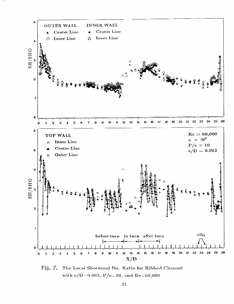
Oa_
"--.3
_Zu_
6 [ OUTER WALL
A Center Lille
[] Inner Line4
INNER WALL
• Center Line
¢r Inner Line
t3 [3
4
0"'*"'"|'" ..... I'""" I"'""1'"'"' I ....... i ,'t ',nrrrr p_n t m ]tr'rT_l t"rrrvn]_ _rrr_n ['rtrrrr_[_rrl]Tt t t rrq''"''' I''''''' I''' ''''1 ''''"'P_ 1'''''1''''''' I''''''' I'''''''1
0 1 2 3 4 5 6 7 8 9 10 11 12 13 H 1,5 16 17 18 19 20 21 22 23 24 25 26
6 _
5 ¸
4
2
TOP WALL
A Inner Line
Center Line
I _ Outer Line
O
0
_ i '
Re : 60,000
o = 900
P/e -- 10
e/D -- 0.063
I O O
t • .
In
(
1 |
.zD
before turn in turn after turn ribs
0 1 2 3 4 5 6 7 8 9 10 11 12. 1:3 14 t5 16 17 18 F:3 20 21 22 23 24 25 26
X/D
Fig, 7, The Local Sherwood No. Rat, io for Ribbed Channel
with e/D::0.063, P/e::l(I, and R e:60.()00
51

O
_q
_0
OUTER WALL INNER WALL
A Center Line • Center Lille
El Inner Line "_ Inner Line
n[3 •
0AJ
0
"¢-_m .... i , • ..... i • • , , ' , • i , ...... i ....... i ....... 1 • • _m-t_ ! ....... ! ....... i .......
8 g 10 11 12 13 14 15 16 17 18
©
Oq
Or)
0
8
TOP WALL Re = 30,000
a Inner Line o = 900 -
• Center Line P/e : 10
o Outer Line e/D = 0.063
1 (9
Q Q
&
I O Q
ribsbefore turn in turn after turn
g 10 11 12 13 14 15 16 I7 18
X/D
Fig, 8, The Local Sherwood No. Ratio for Ribbed Channel
with e/D-0.063, P/e=10, and Re:30,000
52

5 ¸
O 4
or)
or) 3
OUTER WALL INNER WALL
A Center Line • Center Lille
0 Inner Lille _ Inner Lille
I ...... l'''''''|'''''''l'''''''l'''''''l .... Ill I ....... ]I ...... [ ....... ] .......
7-
0 4
oO
_q 3
0
8
TOP WALL Re = 15,000
zx Inner Line a = 900
• Center Line _ P/e : 10l¢
@ Outer Lille e/D -- 0.063
o&
• l O
O
&
n
4[
0 0
A
/X t_
before turn in turn after turn ribs
9 10 I1 '12 13 14 t5 16 17 18
X/D
_iQ, 9, The Local Sherwood No. Ratio for Ribbed Cllannel
with e/D:0.()63, P/e:l(I. an(] Re:15.()(](I
53

©
¢¢)
03
OUTER WALL INNER WALL
• Center Line • Center Line
0 Inner Line _" Inner Line
0
El•
00
5
6 7 8 9 10 11 12 13 14 15 16 17 18 19 20
TOP WALL Re = 30,000
A Inner Line (_ = 900
• Center Line P/e : 20
o Outer Line e/D : 0.063
5
©
(/)_3
O
l
before turn in turn after turn ribs
6 7 8 g 10 11 12 13 14 15 16 17 18 Ig 20
X/D
]=i9, 10, The Local Sherwood No. Ratio for Ribbed Channel
with e/O--0.063, P/e--20= and Re--30,000
54

6-
O
0q_3
0q
OUTER _,VA LL
A Center Line
[] Inner Line
INNER WALL
• Center Lille
Inner Line
O
Id
. qr- _ _,_a.
0
8 9 10 11 12 13 14 15 16 17 18
0
TOP WALL Re = 30,000
A Inner Line ¢x = 900
• Center Line P/e = 10
O Outer Line e/D -- 0.094
I
O
oA
before turn in turn after turn
I_ _i_ _1_ ribs
9 10 11 I2 1:3 14 15 16 17
X/D
Fig, 11, Tile Local Sherwood No. Ratio for Ribbed Channel
with e/D:0.094: P/e:10, and I{e:30,000
18
55

O
f133
rat)
5-
0
cl"l
BiB B
Re -- 30,000
a = 900
P/e --- 10
e/D -- 0.063
.i
before turn in turn after turn ribs
0 1 2 3 4 5 6 7 8 9 10 11 12 13 14 15 16 17 18 19 20 21 22 23 24 25 26
X/D
Fig, ]2, The local Sherwood no. ratio with (x = 900 and Re--30,000
56
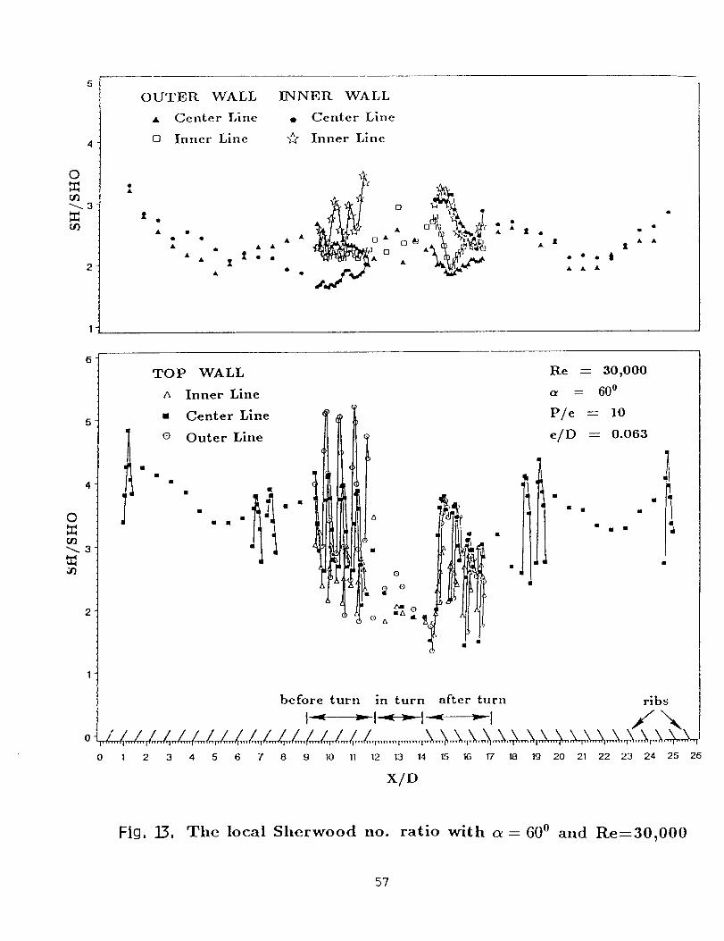
O
_3
¢t)
OUTER WALL
• Center Line
[3 Inner Line
1
i "• AA
A A _oo
A
INNER WALL
• Center Line
Inner Line
••et
AAA
I
0
_3
6 -
TOP WALL
A Inner Line
m Center Line
o Outer Line
• i1 i II •
° jmA
Re -- 30,000
a = 600
P/e -- 10
/i = o.o63
before turn in turn after turn ribs
• i________l_____l _______i _/ x_
0 I 2 3 4 5 6 7 8 9 10 11 12 13 14 15 16 17 18 19 20 21 22 23 24 25 26
X/D
Fig, :13, The local Sherwood no. ratio with c_- 600 and Re=30,000
57

5
4
0j
_3
O3
OUTER WALL INNER WALL
• Center Line • Center Line
o Inner Line _/_ Inner Line
_elO
2
0
0
t
A
0
_3
6-
TOP WALL
a Inner Line
Center LineOuter Line
i
i
Re -- 30,000
a = 450
P/e -- 10
e/D -- 0.063
before turn in turn after turn ribs
////////_, Z/_. \\\\\'4\', ",.......,.......,.......,.......,......., ,/_..d_..._ _.....,.......,.......,..,,.X._._:_._,._......,.......,.......,.......,:,,_ _,%..,0 1 2 3 4 5 6 7 8 9 10 11 12 13 14 15 16 17 18 19 20 21 22 23 24 25 26
X/D
Fig, 1/4, The local Sherwood no. ratio with c_ = 450 and Re----30,000
58

S-
Re _--- 30,000
(r = 600
P/e = 10
e/D 0.063
I
II!
i
after turn
6-
Re = 30,000
5- a = 450 e/D = 0.063
P/e = 10
__ To_wALL
1 I [ .", Inner Li.e
I Ii . Cen,te, Line
0 __ _ Outer Line
lit
_ i T-- I
r_
2-
after turn
6-
3-
O 4-
rat)2-
1-
IIII before turnII
5-
O 4-
rat)
rat)2-
|-
before turn
i *
(_) (b)
Fig, 15, The detailed Sherwood no. ratios on the top wall
with Re=30,000, (a) c_ = 600; (b) c_ = 45 o
59

O
_q
2
OUTER WALL
A Center Line
o Inner Line
I]NNE R WALL
• Center Lille
Inner Line
[3[]
&
[3 []
6
4
_¢1 3 ¸
8
TOP
A
@
O
WALL
Inner Line
Center Line
Outer Line
0 0
Re -- 15,000
= 600
P/e = 10
e/D : 0.063
before turn in turn after turnI _-" _ . ribs
.. L . . . ( .... L . , . / .... /,_-r/_ ....... , .... ,______,_____ ....._-_M-_9 10 11 12 13 14 15 16 17 18
X/D
Fig, 16, Tile local Sherwood no. ratio with c_ = 600 and Re--15,000
60
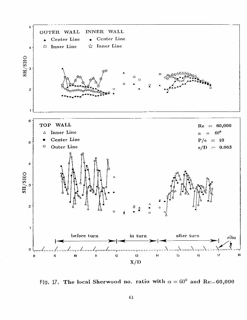
©
r/)_3
OUTER WALL ENNER WALL
• Center Line e Center Line
o Inner Line _" Inner Line
o _..-_. _k" J L_°d .A" *_'_s(,_.._
• 1. / .A_."" - _.& Ae,_ A _ []
5
4
O
_3
TOP WALL
A Inner Line
• Center Line
o Outer Line
FP
t$
O
8
before turn
I :-= "-: I -_
,.1 .... /....l,,.l...,I,.,.l...,9 10 11 12
Re -- 60,000
a = 600
P/e -- 10
e/D -- 0.063
I• 0
in turn after turn ribs
13 14 15 16 17 18
X/D
Fig, 17, The local Sherwood no. ratio with _--600 and Re----60,000
61

4
0
¢/)
_a
OUTER WALL
• Center Line
o Inner Line
IINNER WALL
• Center Line
"_ Inner Line
yl [] []
• &
[3 []
7"
6'
4
¢11
3
TOP WALL
a Inner Line
@
A
Center Line
Outer Line
before turn in turn
8 9 10 !1 12 13
X/D
Re -- 15,000
= 450
P/e = 10
e/D -- 0.063
l
after turn ribs
14 15 16 17 18
Fig, 18, Tile local Sherwood no. ratio with _ = 450 and Re--15,000
62

5
C)
033
00
OUTER WALL
• Center Line
t3 Inner Line
INNER WALL
• Center Line
"_ Inner Line
A
[3
[3
AK
O
3
0q
2
TOP WALL
Inner Line
• Center Line
o Outer Line
Re = 60,000
a -- 45o
P/e = 10
e/D = 0.063
I
Q0
"<y_O i
I I I a erturn ibefore turn in turn . ,
8 9 10 11 12 13 14 15 16 17 18
X/D
Fig, 19, Tile local Sherwood no. ratio with a = 450 and Re=60,000
63
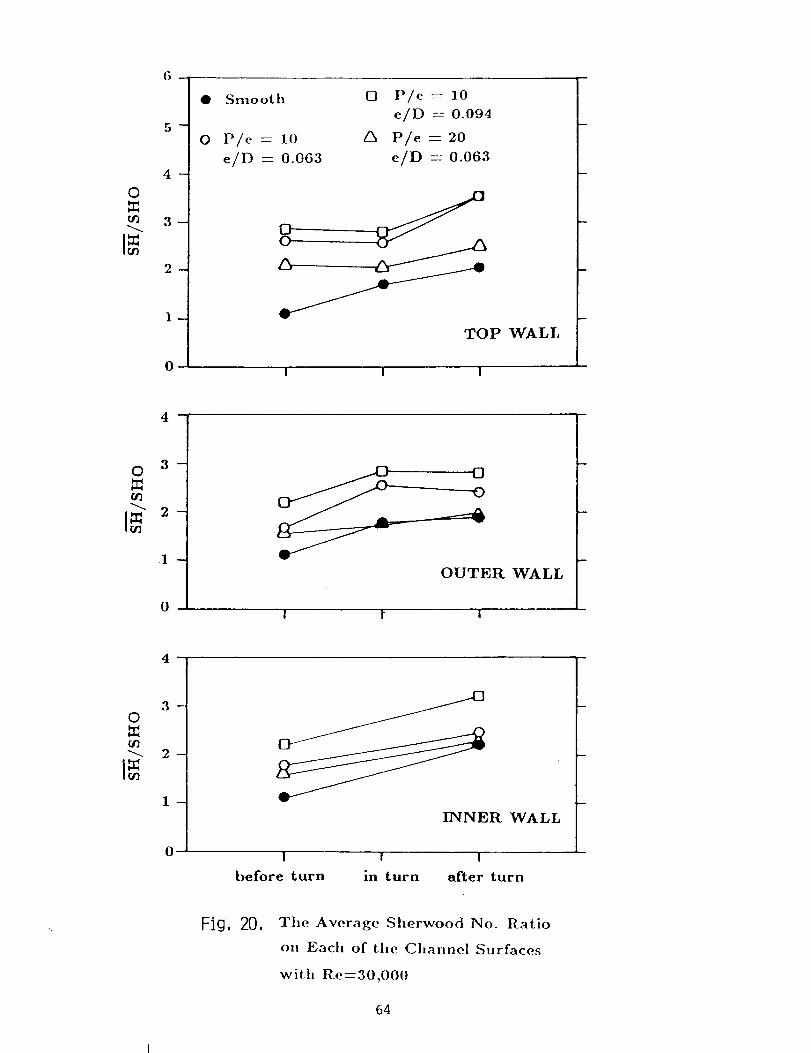
6-
o:iO3
_
_
0
O
Smo ot h
P/e = 10
e/D = 0.063
O P/c = 10
e/D = 0.094
P/e = 20
e/D = 0.063
OO
/3
TOP WALL
I I I
o
I-
,
OUTER WALL
I t I
0
4
I m
0
_NER WALL
I I I
before turn in turn after turn
Fig, 20, The Average Sherwood No. Ratio
on Each of the Channel Surfaces
with Re=30,000
64
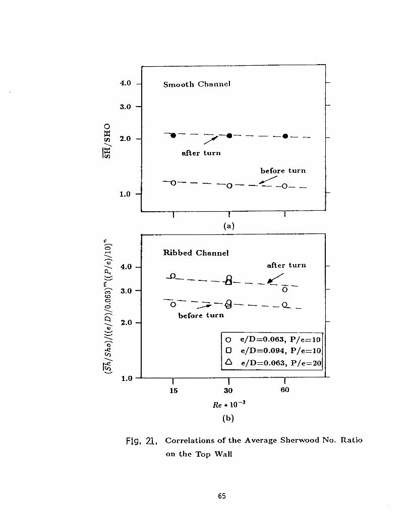
0
_q
o
"C
v
4°0 --
3.0 --
2.0 --
1.0 --
4.0 --
3.0--_DO
O
2.0-
vv
%
Smooth Channel
---0---- __,_--Q
after turn
before turnJ
--o .... o -- --"/-- -o- _
i I I
(a)
Ribbed Channel
after turn
0
--b-- -__--0 .... o___before turn
O e/D--0.063, P/e--10
0 e/D--0.094, P/e--10
A e/D--0.063, P/e=20
1.0- [ i ]15 30 60
Re * 10 -_
(b)
Flg, 21, Correlations of the Average Sherwood No. Ratio
on the Top Wall
65

4
_
O
O0
4
_
O
0¢]
[:_ 2_f/]
_
O 3 -
g0
C) TOP WALL
A OUTER WALL
I--] INNER WALL
before turn
1 I 1 I 1 I I
in turn
I I I ! I I I
©
©
_
.
_
_
i
4
3_
2
__
(_) a = 900
a = 600
_] _ = 450
TOP WALL
OUTER WALL
INNER WALLafter turn
i 1 1 1 I 1 1 ! I I
before in after90 o 60 o 30 o
turn turn turn(_
Fig, 22, The average Sherwood no. ratio on each of the
channel surfaces with Re--30,000
66
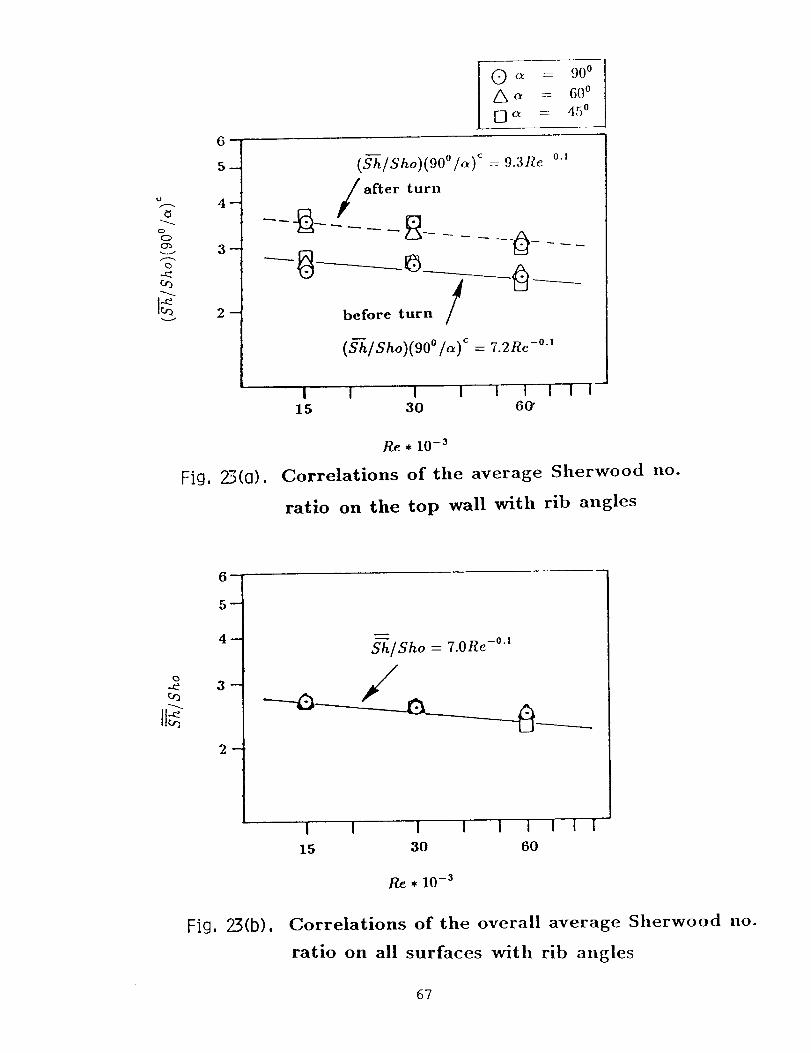
_3
%-3--
2--
(_ c_ = 900
a = 60 o
O c_ = 450
(S-h/Sho)(90 °/_)¢ :: 9.3Re -°'
after turn
before turn /
(_hlSho)(90 °1_)< = 7.2Re -°-'
J
I I i I I I I I I15 30 60'
Re * 10 -3
Fig, 2:3(0), Correlations of the average Sherwood no.
ratio on the top wall with rib angles
6_
5--
4-
Fig, 23(b),
"_/Sho = 7.0Re -°'1
I I i I I I I I I
15 30 60
Re * 10 -3
Correlations of the overall average Sherwood no.
ratio on all surfaces with rib angles
67

0
O3
=
4.0--
3°0--
_o0--
1.5--
1.0--
Average Average
before turn in turn
O A• •
Average
after turn
I_ --- this study
n -- Metzger
and Sahm (1985)
& • z5
I I I
(a)
0
O3
4,0--
3.0--
2.0--
1.5--
1.0
Fig,
P/e-----lO P/e--20 ]• • -- this study
0 ,/_ --Han et al. (1985)
-O- -_- --nan et al. (1986) I
Top Wall(before the turn)
24,
1 ! 115 30 60
Re • 10 -3
(b)Comparison between tile present results
and the publist, ed heat tra,_sfer data
68
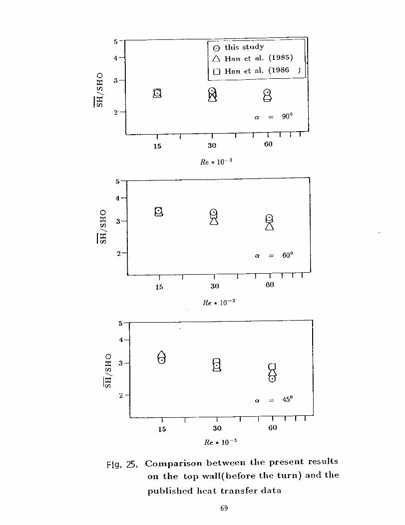
0
rat)
_
I
15
(:) this study
Z_ Han et al. (1985)
[__7Han et al. (1986
I l I
30
Re * 10 -3
a = 900
I I I I
60
0m
m
I
15
I I
30
Re * 10 -3
a = 600
I I I 1 I60
r
_
03-
O3
0
I 1
15
I I3O
Re * 10 -3
= 450
I I ! I 160
Fig, 25, Comparison between tile present results
oil tile top wall(before the turn) and the
published heat transfer data
69

Wi
Q.
0F-
0
% %
o c_
o
o
_Erc_ _
o
o
r- 0
o
o
E U.Im-- 0
0
_l.t/C_I
a
E 0
0Ev
Ec0
...... :o do
_f-..--_-f
0 c* 0
zl0
U5U5Q)
c_
Q)
c-
v-
©°--
uQ)u_
4_0u_Q)
r-
g-O
t3 C
E
ZZ c_X
Cq
EL
?0

II II II II II II
oo_qol
I I I I
k LL*_(*.,l
0
o)
t_-(,o
L_
E
t
E
r _
_- o0
I
EE(13
_EU
.E_J00Em
0
(1)
D
Q.
t_(1)
r-0
o_
fflE
Eo_
n
e,4
LL
71

LQ
(5I
0,1
0,1
O3
0,1
04
0,1
0O4
CO
(13
04,r-
0
F o_
CO
D,-
_3
.- LO
E
,,r- o
0
r_!
q_
C
U _
O
E
o d
(Z)
L (Z)
m nI1)
_ dif)(1) ,---t
c IIO _
c 13_(1)
c_°F--I
I.L
72

04
0O4
r-- COI:: '_-
F
.'- o_F-
E
I°t_
o,,i
I,_ 0 _ 0 _ 0 _ 0 I.,0
I I I I I I I I I
- v--
i
o
zAd/('""_d -d)_;
Cr"
¢-.t.) o
0
03
o1,,=..
¢..-t_
O.
o ,4•"_ t.O
0
x_. 0
= IItt_
x..E). _0
dtt_
0
r- 12.
E '-"
D
g]d_
o*--.,I
ii
73

II II II II II II
oO_4om
0
Ico
u-i
E_
o
_0
m
,t--
o
i °00
E
E
o
I
c-c-
C"
lab
O3
0
O_
o"1_ kO
0
l._ 0
L/)
6U3
0
c- 13_fl)
4--1
a _
74

/II II II II II II
O4
O4
_4
_ 0404
_ 004
2
g
I I ! I I I I I I
F
E
L_
E
7-
EL
-- (D
E
,£
r-
E-
%
z
_- o
o
I
c-c-¢0
c-u _
O_
O
M_
_o c-
D_
ok_
7D _)O
=- O
D
D_ 03
o-t/)q_ ("4
O
c- nq)E =
°-- .__
°_,,_
Ii
75

II II II II II II
o0_4 om /I
/
/!
!
If
/
i t,o
L
E c_t
E
f_E
i-
p=-
E
!:r-
I-
FEbE
gEI.-
v--- c,_
r.
I II I I I I I I I I I I I I I I I
c"(-
¢-U _0¢-- G_o"1
0,-- _31,,-.
,9.0_Cr'_
o•"_ 0"1
0
_- 0
I,fl
c5
= II0
_- 12.
E =4-_
C3 _
c_t.l_
?6

/;/
/iii
/
/
(D
II II II II II
II II II II II
"ZII II II II II
o4Q<] NO
o
r,Ad/(_"'"d -d)_:
c-o
c-L)
c-CY)
Ok--
_oo=O
"ID
o3i/)
'-- c_o_O
m Ot/7
O
o II
c
E _c
c3
°_.--I
LL
77

/
I I I I I I I I I I I I I I I I I I
¢,Q0,1
tl)
0,,I
0Ol
In
IxlI,,-.
o
CO
CO
t,O
0
w
c'-c'-
U
c-
OI,.,-
Q.o
1,,.,..
:3t¢)tel
"- 6O.0
u_ 0
0
E mo II
E .cC3 _
c_•,-,,iIn
78

II il II II ii
0 _DCD
liIIiltlII
II_II ilIIIIII
04 D(]I •
, .... i , 1 ' u • i , i , T ' I ' I • n ' _ ' U ' n ' u • I ' I '
L
L",,I
0
k- t"--
,r--
L_,,,-.
0
f,,..
o
I I I ! I I I I I I I i I i I ! _"
-d)C
C
U
0
0
II}
- (50
C)
_} o{-- Loo II
c 12:
E _-
c_
79
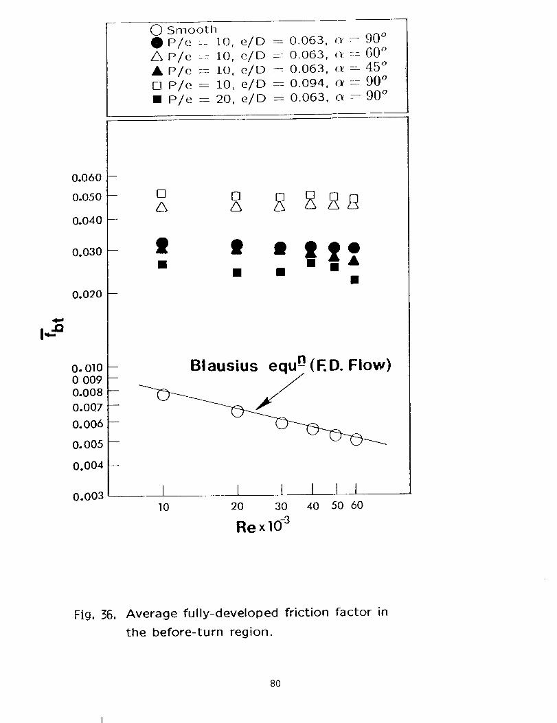
0 SmoothO P/e == 10, e/D _--- 0.063, o'-- 90 °
A P/e :-:: 10, e/D =--: 0.063, (:_ -- 60 °
A P/e -- i0, e/D = 0.063, _ = 45 °
[] P/e = I0, e/D --=- 0.094, c_ = 90 °
m P/e = 20, e/D -- 0.063, c-t = 90 °
0.060
0.050
0.040
0.030
0.020
O. 0100 009
0.008
0.007
0.006
0.005
0.004
m
[] []
' ' "I|![] • • n
Blausius equ -n(ED. Flow)
0.003 II0
I I I I I20 30 40 50 60
RexlO -3
Fig, 36, Average fully-developed friction factor in
the before-turn region.
80

_ S_rlootllP/e -- 10, e/D -- 0.063, (Y - 90 °
AP/e = 10, e/D = 0.063, 4_ =- G0 °
• P/e = i0, e/D = 0.063, (r--45 °
[] P/e = i0, e/O -- 0.094, _._ ---- g0 °
[] P/e = 20, e/D -- 0.063, cr :--- 90 °
0.06O
0.050
0.040
0.030
0.020
0.0100.0090.008
0.007
0.006
0.005
0.004
m
m
[][] [] [] [] []
ZS ZS Z_ ZS Z_ SS• •t • 0 • 0• / / u n
0
00
Ooo
0.003 -- ---JI0 20 30 40 50 60
Blausius equ -n (ED. Flow)
I I I 1 t
RexlO -3
Fig, 37. Average fully-developed friction factor in
the after-turn region.
81

OSmoothOP/e = 10, e/D -- 0.063, o_ ----- 90 °
AP/e -- 10, e/D ----0.063, o_- O0 °
A P/e -- I0, e/D ---- 0.063, c_ -- 4,5 °
[] P/e -- 10, e/D -- 0.094, o_ -- 90 °
• P/e --- 20, e/D ---0.063, o_-----90 °
6.0
5.0
4.O
3.0
2.0
U
1.00.9
0.8
0.7
0.6
0.5
0.4
0.3
m
O
10
O0 000
i i I I I20 30 40 50 60
Re x 10-3
Fig, 58, Loss coefficient in the entrance region.
82

O SmoothO m/e -- I0, e/D ----O.O63, oc -- 90°A p/e- 10, e/D --O.063, o_- 60°AP/e-- 10, e/D --0.063, _- 45 °
[] P/e -- 10, e/D _ 0.094, o_---90 °
[] P/e --- 20, e/D -- 0.063, o_ -_ 90 °
4.-I,
4.0
3.0
2.0
1.00.9
0.8
0.7
0.6
0.5
0.4
0.3
I
[] [] [] [] [] []
• • • 0 O0
110
I I I 1 I20 30 40 50 60
RexlO-3
Fig, 39, Loss coefficient in the turn region.
83


APPENDIX A
NATURAL CONVECTION LOSS
PI.C,BCgl)[IqG PAGB BLANK NOT g_
85

The mass transfer from a surface has direct relationship with
the local Sherwood 7_.un_ber and the local heat transfer coefficient.
Therefore, in a mass transfer experiment, it becomes very critical to
account for the exact transfer of mass taking place during the test
run only.
In the present investigation, the naphthalene coated plates
were sealed in air-tight plastic bags when they were not in use.
But during assembling and disassembling the test apparatus, the
naphthalene plates were in the open for about 30 minutes each time.
The main factor to consider is the time during which the surface
contour measurements were performed before and after the test
runs. Depending upon the geometry of the plate, i.e. Top Plate
(big) or the Side Plate (small); Smooth Plate or Rough Plate; Rib
placement at right angle(90 °) or acute angle(60 ° or 45°), the time
taken in the measurement and in turn the mass transfer" by natural
convection will be different in each case. The time taken in the
measurement of different surfaces was recorded. The maximum
time (about 2 hours) was recorded for the top plate with ribs at
an angle-of-attack of 60 ° and 45 ° , as the local contour measurement at
the grid stations was more complicated.
In order to account for this mass transfer due to natural
convection in data analysis of the Sherwood TI,UTn,b_:r, _-.p,,r,_,._
experiments were conducted to record the depth change of the
naphthalene surfaces with respect to time. The fresh naphthalene
coated Top Plate was kept open on the measurement table in
the laboratory for 2 hrs. The depth was measured and recorded
86

at nine locations(as shown in the figure below) at an interval of
30 minutes. These locations were selected to cover all the three
important regions, i.e. before-turn, in-turn, and after-turn. The
depth change at these points with respect to time is given in the
table on page 89.
9 8 7• • •
• • •1 2 3
06
Q5
04
TOP WALL
1.27 cm
A plot betWeen the depth change (AZ) versus duration of time
(/_) was drawn and shown in the figure on page 88. The curve fit through the
data points gives two equations (1) and (2)to account for the depth
change for two different time periods.
AZ = (At- 10)/10000 forAt < 70 (1)
AZ = (18 + 0.6At)/10000 forAt > 70 (2)
Using these equations, depending on the time for which each plate
was in the open, the correction for depth change was taken care of
in the data analysis.
87

.......... 0
EE
f-.
000d
0+
• • •
_ 0
0_1 0 00 tO "_" 0_1 00 0 O 0 0
o. o o o o oo o o d d d d
(,.uw)Z_7
88
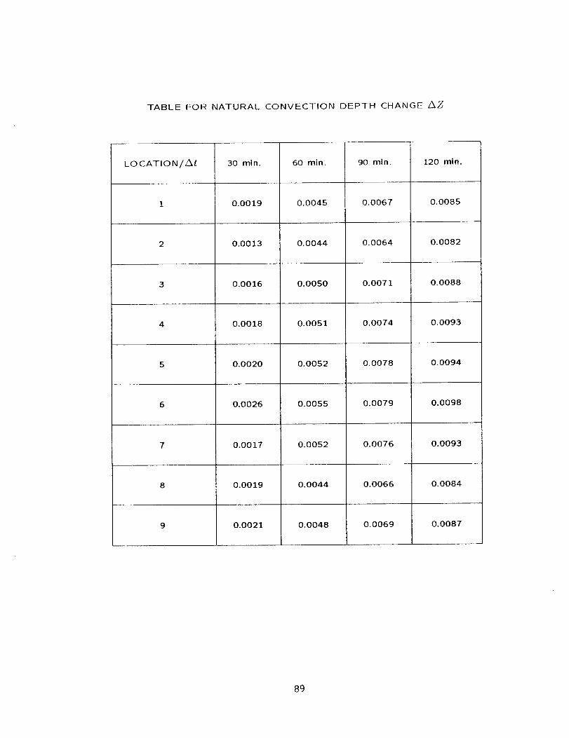
TABLE FOR NATURAL CONVECTION DEPTH CHANGE Z_Z
LOCATION/Z_
2
9
30 mi n.
0.0019
0.0013
0.0016
0.0018
0.0020
0.0026
0.0017
0.0019
0.0021
60 min.
0.0045
0.0044
0.0050
0.0051
0.0052
0.0055
0.0052
0.0044
0.0048
90 mln.
0.0067
0.0064
0.0071
0.0074
0.0078
0.0079
0.0076
0.0066
0.0069
120 min.
0.0085
0.0082
0.0088
0.0093
0.0094
0.0098
0.0093
0.0084
0.0087
89

APPENDIX B
HEAT/MASS TRANSFER DATA
90

m f.. t"
0 0 "--
I I I
J d .-
_5 _2. _
T T
i
T T
T T
I i
u m
I I I
_ 0 --
DR/GINAE PAGE _
PE POOq gIT,_t.TTy
E i I _ 1 f I I I
I I i I I I t I I _
tt-
O
I I i I I I
_ __ -_ __ = __ o_ __ o_ __ = .--:"
, I , T T T
n
¢-¢-.
0
I _ I I I I I i I I I_ = _ , __ , __ , __ , __ , __ , __ , __ , __ , __.
ol : i" ? "_ ? ? "i' i" T ? oI
0
¢-
91

•-- I::: e"
e" ..., I::_) 3 e"0 0 "--
I. I. I._i (:i .-
k k
! I
_ _" _ == _
I Io
I I
I I
I I
.4 .-:I I
_ _
I I
I I
m nM m
I I I
_ d -"
ci
ORIGINAL PAGE, "'_;
OF POOR qUA_
I " I I1111_||III/l/I)iq
.......................... O
7 I T _ II_lllIItllilllill
I I I I IIIliillllliililll
tr-
0
r_
Illilllillllllltll
II111111111tlli111
illlIllllll11111_1
ItLittll ilil tli
_ _N_'_ O
, I i I 1i111111 _ Ililllll _ =
T r 7 ? 77T77T?? 7777TT?r_
-_-_-_-_7? 7
N
7 7 ?
T T T- _ _ _
r-
:3
OOO)II
E)O
(5II
o"',r'-
(DII
1111111111iilllili
IIIIIIIII1illltl
I _ I I llllllllllllllllil
, r I I _7TTTTTT?TTTTTTTo ! TTTTrrrTTTTTT
I,==
o
Or-
CO
(/)
92

m
Q. _-"
_.o_=t I t d
_ 0 --
I IIIILllll I
tllllllllllli
_ 8 _ _ _ _ _ _ _ _ _ _ _
i 1 i I I 1 1 1 1 1 1 1 1
i i _ 1 lllilllll_Iil
-- _ -- _-- _-- _ -- . ..............
I I i _ llliIliil_llll
II
re
O
oe-
93

_-0 -I I I d
I-: 0 --
r-
I I I I I I I 1 I I I I
I I I I Illillllllll
t I I 1 IIIIIIIIIIIII
0
I,.._
0
0
¢/)
94 ORIGINAL PAGE IS
OF ._)OR QUAy,

Table 1. AVERAGE REGIONAL SH/SHo RATIOS
Re
xlO -3
15
3O
60
15
3O
6O
"15
3O
6O
15
3O
6O
3O
3O
P/e
]0
10
10
10
10
10
10
10
10
20
10
e/D
0.063
0.063
0.063
0.063
0.063
0.063
0.063
0.063
0.063
0.063
0.094
TW]
1.14
- 1.09
- 1.08
90 ° 2.53
90 ° 2.61
90 ° 2.48
60 ° 3.37 -
60 ° 3.29
60 ° 3.03
45 ° 3.07.... I
45 ° 2.86I
45 ° 2.29
90 ° 2.12q
90 ° 2.85
TW2 TW3
l
1.73_r - 2.07
2.40 3.53___ _ _-_--------_
2.55 13.50J
2.23 12.99
_ 2.91
2.17 2.75
1.92 2.80
2.80 2.93
2.63 3.14
1.87 2.62
2.06 2.49
2.80 3.50
OWl
-1-1%-1.13
1,04
1.82
1.67
1.52
2.37
2.24
2.00
2.00
2.03
--1.91
1.55
2.20
OW2
1.13
1.12
2.09
2.13
1.82
2.27
2.12
2.03
2.28
2.12
1.69
1.62
2.29
OW3
2.10
1.82
1.66
3.01
2.56
2.54
3.11
2.37
2.35
1.96
2.10
2.00
2.05
2.88
OW4 OW5
2.25 1.81
2.17 1.86
1.93 1.86
3.49 2.72
2.77 2.39
2.44 2.35
2,63 2.10
2.57 2.15
2.43 2.33
3.60 : 2.39
2.86 ! 2.25
2.35 2.33
129 V;4-3.31 2.80
IWl IW2
1.15 2.16
1.12 2.18
1.13 2.20I
1.73 2.74
1.78 2.44 II
1.48 2.53 I
2.05 3.00 I
2.25 I 2.76 [
2 12TA-I
2.35 2.93 I
198j 26!j2.03 2.80 ]
2.201 3 20
Re REYNOLDS NUMBER
P/e ' PITCH-TO-RIB HEIGHT RATIO
e/D • RIB HEIGHT-TO-HYDRAULIC DIAMETER RATIO
Q • RIB ANGLE-OF-ATTACK
REGIONS:
TW1
TW2
TW3
OWl
OW2
OW3
OW4
OW5
IWl
IW2
: TOP WALL BEFORE-TURN (X/D----9.0 to 12.0)
: TOP WALL IN-TURN (X/D_-12.0 to 14.0)
: TOP WALL AFTER-TURN (X/D=14.0 to 17.0)
: OUTER WALL BEFORE-TURN (X/D-----9.0 to 12.0)
: OUTER WALL IN-TURN (X/D=12.0 to 12.5)
: OUTER WALL IN-TURN (X/D=12.5 to 13.5)
: OUTER WALL IN-TURN (X/D=13.5 to 14.0)
: OUTER WALL AFTER-TURN (X/D=14.0 to 17.0)
: INNER WALL BEFORE-TURN (X/D=9.0 to 12.0)
: INNER WALL AFTER-TURN (X/D----14.0 to 17.0)
95

Smooth Channel Re- 15,000
S h / Sh o
TOP WAI,L
X/D O.L. C°L. ] °L.
BEFORE TURN
8.313 1.014 1.014
8.938 1.033 0.9846
9.563 1.054 1-006
10.125 1.178 1.030
10.375 1.140 1.159
10.625 1.042 1.069
10.875 1.186 1.212
11-125 1.306 1.213
11.375 1.366 1.295
11.625 1.523 1.318
IN TURN
11.875 1.900 1.562
12.375 1.407 1.787
12.875 1.738 1.836
13.125 1.985 1.612
13.625 2.014 2.130
14.125 2.132 2.031
AFTER TURN
1 023
1 030
1 073
1 O57
1 239
1 133
1 187
1 202
1 098
1 106
1 477
1 853
1 834
1 500
1 596
1 796
14.375 2-260 2.025 2.080
14.625 2.301 1.982 2.442
14.875 2.244 1.789 2.483
15.125 2.300 1.716 2.465
15.375 2.356 1.763 2.408
15.625 2.201 1.772 2.398
15.875 2.106 1.805 2.349
16.438 2.166 2.114 2.193
17.063 1.976 1.947 1.840
17.688 1.672 1.673 1.644
96

OUTER WALL AND INNER WALl,
X/D I.L. C.L. ] .1.. C.h°
BEFORE TURN
OUTER WALL INNER WALL
8.313 1.186 1.105 0.983 0.946
8.938 1.256 1.204 1.087 1.021
9.563 1.233 1.104 1.218 1.182
10.125 1.213 1.057 1.061 0.989
10.375 1.327 1.089 1.147 1.045
10.625 1.310 1.073 1.195 1.109
10.875 1.197 1.050 1.251 1.172
11.125 i.i00 1.021 1.278 1.235
11.375 1.165 1.060 1.455 1.326
11.625 1.311 1.044
IN TURN
11.875 1.365 1.047
12.375 1.548 1.450
12.875 2.116 1.983
13.125 1.960 2.113
13.625 2.041 2.240
14.125 2.123 2.598
AFTER TURN
14.375 2.058 2.505
14.625 1.752 2.380 1.457 1.586
14.875 1.474 2.194 1.725 1.832
15.125 1.285 2.083 2.281 2.102
15.375 1.268 1.956 2.584 2.397
15.625 1.502 1.911 2.867 2.618
15.875 1.860 1.852 2.847 2.697
16.438 1.810 1.861 2.326 2.138
17.063 1.607 1.650 2.110 1.843
17.688 1.540 1.631 1.787 1.651
97

Smooth Channel: Re -- 30,000
Sh/Sh oTOP WALL
X/D O° m. C° h. _ ° [_.
BEFORE TURN
1.125 2.559 2.731 2.819
2.125 1.523 1.499 1.647
3.125 1.357 1.328 1.429
4.125 1.234 1.251 1.259
5.125 1.203 1.193 1.156
6.125 1.222 1.158 1.080
7.125 1.171 1.070 1.121
8.125 1.122 1.012 1.063
9.125 1.081 1.008 1.044
10.125 1.116 1.049 1.099
10.375 1.058 1.095 1.183
10.625 1.007 1.009 1.132
10.875 1.025 1.014 1.093
11.125 1.068 1.015 1.068
11.375 1.107 1.122 1.103
11.625 1.319 1.186 1.124
IN TURN
11.875 1.521 1.368 1.333
12.375 1.104 1.548 1.549
12.875 1.891 1.911 1.681
13.125 1.911 1.797 1.609
13.625 2.043 2.110 1.471
14.125 2.196 1.800 1-810
98

AFTER TURN
14.375 2.282 1
14.625 2.267 1
14.875 2.126 1
15.125 2.150 1
15.375 2.106 1
15.625 2.117 2
15.875 2.015 2
16.875 1.765 1
17.875 1.675 1
18.875 1.523 1
19.875 1.337 1
20.875 1.187 1
21.875 1.070 1
22.875 1.045 1
23.875 1.019 1
24.875 1.431 1
.840
.951
.860
.870
.954
-008
.074
.864
.642
.387
.220
.174
.062
.055
.052
.380
2.108
2.403
2.478
2.55O
2.538
2.499
2.389
1.775
1.463
1.282
1.158
1.075
1.018
1.010
1.012
1.634
99

OUTER WALL AND INNER WALL
X/D I .L. C.L. I .L.c.n.
BEFORE TURN
OUTER WALL INNER WALL
1.125 2.333 2.289 2.490 2.056
2.125 1.900 1.700 1.840 1.655
3.125 1.600 1.500 1.548 1.442
4.125 1.410 1.300 1.387 1.264
5.125 1.326 1.260 1.201 1.256
6.125 1.150 1.206 1.202 1.103
7.125 1.136 1.145 1.217 1.077
8.125 1.150 1.097 1.050 1.064
9.125 1.173 1.125 1.055 1.072
10.125 1.213 1.113 1.130 1.106
10.375 1.238 1.064 1.107 1.084
10.625 1.252 1.045 1.117 1.064
10.875 1.136 1.045 1.183 1.061
11.125 1.158 1.008 1.176 1.089
11.375 1.128 1.049 1.207 1.154
11.625 1.261 1.071 1.281 1.228
IN TURN
11.875 1.297 1.108
12.375 1.375 1.308
12.875 1.970 1.855
13.125 1.700 1.883
13.625 1.810 1.878
14.125 1.984 2.472
1O0

14 375
14 625
14 875
15 125
15 375
15 625
15 875
16 875
17.875
18.875
19.875
20.875
21.875
22.875
23.875
24.875
1.900
1.732
1.530
1.437
1.630
1.863
2.123
1.784
i. 578
1. 496
1.408
1.345
1.176
0.9526
1.066
AFTER TURN
2.359
2.205
2. O97
1.912
1.816
1.869
2.151
1.923
1.630
1.597
1.436
1.424
1.232
0.9493
1.188
1.532
1.7"79
2.201
2.546
2.747
2.684
2.620
2.028
1.823
1.455
1.281
1.080
1.170
1.167
1.499
1.465
.594
718
102
4O3
574
596
592
.983
.778
.517
.208
.135
.174
.245
.643
.259
i01

Smooth Channel Re -- 60,000
Sh/Sh o
TOP WALL
X/D O.L. C.L. I .L.
BEFORE TURN
8.125 1.174 1.191 1.179
9.125 1.061 1.061 1.075
10.125 1.105 1.035 1.051
10.375 i.i00 1.027 1.081
10.625 1.074 1.014 1.063
10.875 1.027 1.013 1.037
11.125 1.001 1.050 1.012
IN TURN
11.375 0.9806 0.9919 0.9865
11.625 1.147 1.117 1.115
i1.875 1.315 1.350 1.377
12.375 1.106 1.482 1.492
12.875 1.882 1.688 1.562
13.125 1.933 1.735 1.535
13.625 2.122 1.958 1.518
14.125 2.076 1.825 1.549
AFTER TURN
14.375 1.540 1.462 1.779
14.625 1.426 1.602 1.947
14.875 1.471 1.706 2.239
15.125 1.688 1.916 2.558
15.375 1.994 2.207 2.755
15.625 2.259 2.425 2.754
15.875 2.472 2.583 2.649
16.875 2.261 2.265 2.076
17.875 1.845 1.924 1.887
102

OUTER WALL AN_D INNER WALL
X/D I .L. C.L. I .L. C.L.
BEFORE TURN
OUTER WALL INNER WALL
8.125
9.125
10.125
10.375
10.625
10.875
11.125
11.375
11.625
11.875
12.375
12.875
13.125
13.625
14.125
14.375
14.625
14.875
15.125
15.375
15.625
15.875
16.875
17.875
1.150
1.O95
1.130
1.169
1.094
1.068
1.O32
0.930
0.983
1.082
1.447
1.690
1.683
1.765
1.645
1.390
1.384
1.275
1.551
1.960
2.052
2.180
1.788
1.652
1 2OO
1 i00
1 127
1 139
1 004
0 964
0.900
0.851
O.83O
IN TURN
0.970
1.274
1.745
1.659
1.784
2.223
AFTER TURN
1.828
1.831
1.737
1.921
2.212
2.407
2.498
2.007
1.824
1.102
1.065
1.127
1.071
1.058
1.076
1.084
1.285
1.367
1.708
2.027
2.319
2.527
2.703
2.560
2.471
1.969
1.670
1.130
1.061
i.i01
1.065
1.035
1.046
1.041
1.276
1.338
1.842
1.964
2.275
2.417
2.471
2.476
2.524
1.966
1.656
103

Rough Channel Re--15,000, P/e=10,
Sh/Sh o
_O_ WALL
e/D---0.063, o:- 90 °
X/D C.L. C.L. ]. L.
BEFORE TURN
8.313 3.322 2.835 2.625
8.938 3.131 3.045 2.898
9.563 2.686 2.520 2.36_
9.938 2.165 1.656 2.300
I0-000 3.355 2.802 2.820
10.063 3.620 3.200 3.141
10.125 3.261 2.874 2.794
10.188 3.067 2;593 2.414
10.250 2.611 2.170 2.166
10.313 2.483 1.956 1.942
10.375 2.498 1.906 1.848
10.438 RIB RIB RIB
10.500 RIB RIB RIB
10.563 2.470 2.325 2.571
10.625 3.374 2.936 2.878
10.688 3.691 3.156 3.521
10.750 3.206 2.661 2.354
10.813 3.013 2.588 2.357
10.875 2.703 2.148 2.134
10.938 2.522 1.969 1.922
i!.000 2.300 1.747 1.732
11.069 RIB RIB RIB
11.125 RIB RIB RIB
11.188 2.497 1.967 1.609
11.250 3.660 2.797 2.461
11.313 3.694 3.037 2.829
11.375 3.097 2.547 2.393
11.438 2.832 2.411 2.226
11.500 2.237 1.881 1.856
11.563 1.612 1.693 1.647
11.625 2.649 1.528 1.471
104

IN TURN
11.875 3.723 3.308 3.20012.375 1.874 2.303 2.37812.875 2.692 2.329 1.68813.125 2.282 2.213 1.50713.625 3.300 2.537 I..65814.125 2.194 1.537 1.273
AFTER TURN
14.375 2.282 1.583 1.34:14.438 6.306 2.345 1.71014.500 6.383 2.619 2.27114.563 6.161 3.301 2.44914.625 4.536 3.427 2.58514.688 4.353 3.628 2.93614.750 2.592 3.401 2.43914.813 3.426 3.591 2.44614.875 RIB RIB RIB14.938 RIB RIB RIB
].5.000 1.853 3.051 2.646
15.063 5.480 4.741 3.376
15.125 5.989 4.763 3.37_
15.188 6.186 4.460 3.091
15.250 5.799 4.363 2.970
15.319 5.203 3.907 2.399
15.375 3.325 3.503 2.139
15.438 4.181 3.066 1.961
15.500 RIB RIB RIB
15.563 RIB RIB RIB
15.625 2.079 2.029 2.250
15.688 3.525 3.474 2.933
15.750 4.472 3.952 3.454
15.813 5.958 4.213 3.135
15.875 5.543 3.916 2.95"7
15.938 5.226 3.893 2.702
16.000 3.415 3.166 2.512
16.O63 4.335 2.856 1.970
16.438 3.855 3.216 2.810
17.O63 5.107 3.755 3.065
17.688 3.915 3.376 2.837
105

OUTER WALL AND INNER %_ALL
X/D I .L- C.L. ! .L. C.L.
BEFORE TURN
OUTER WALL INNER WALL
8.313 2.019 1.826 2.320 2.313
8.938 1.761 1.884 1.981 1.828
9.563 1.640 1.717 1.580 1.607
9.938 1.840 1.604 1.401 1.486
IO.OOO 1.780 1.599 1.231 1.425
10.125 1.791 1.654 1.340 1.720
10.250 1.692 1.709 1.590 1.574
10.375 2.118 1.666 1.708 1.662
10.500 1.869 1.907 2.002 1.749
10.625 1.827 1.843 1.838 1.770
10.750 1.794 1.756 1.966 1.703
10.875 1.718 1.572 1.941 1.722
ll.OOO 1.890 1.701 2.003 1.752
11.125 2.010 1.800 2.046 1.655
11.250 1.892 1.833 1.926 1.633
11.375 1.956 1.780 1.83H 1.482
11.500 1.955 1.758 1.505 1.555
11.625 2.168 1.993
106
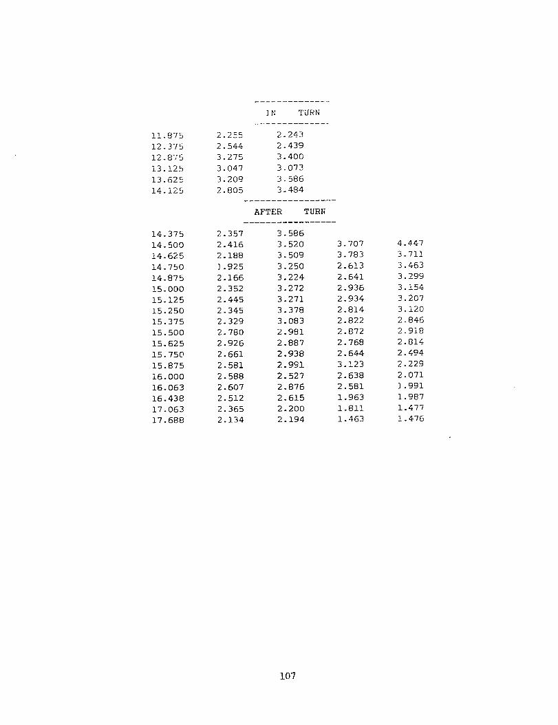
11.87512.37512.87513.12513.62514.125
14.37514.50014.62514.75014.87515.00015.12515.25015.37515.50015.62515.75015.87516.00016.06316.43817.06317.688
2.2552.5443.2753.0473.2092.8O5
2.3572.4162.1881.9252.1662.3522.4452.3452.3292.7802.9262.6612.5812.5882.6072.5122.3652.134
IN TURN
2.2432.4393.4003.0733.5863.484
AFTER TURI_
3. 5863.5203. 5093.2503.2243.2723.2713.3783.0832.9812.8872.9382.9912.5272.8762.6152.2002.194
3.7073.7832.6132.6412.9362.9342.8142.8222.8722.7682.6443.1232.6382.5811.9631.8111.463
4.4473.7113.4633.2993.1543.2073.1202.8462.9182.8142.4942.229
2.071
1.991
1.987
1.477
1.476
107

Rough Channel: Re----30,000, P/e----10,
Sh/Sh o
TOP WALL
e/D=0.063, o_ -- 90 °
X/D O.L. C.L. I .L.
BEFORE TURN
0.563 1.369 0.9620 0.9345
0.625 1.609 1.431 1.782
0.688 2.014 1.930 2.302
0.750 2.399 2.154 2.676
0.813 2.265 1.812 2.277
0.875 1.965 1.828 2.345
0.938 1.649 1.358 2.164
1.000 2.194 2.710 3.014
1.063 RIB RIB RIB
1.125 RIB RIB RIB
1.188 2.026 1.441 1.181
1.250 3.179 2.708 3.677
1.313 3.788 3.079 4.019
1.375 4.170 3.662 4.198
1.438 3.972 3.517 3.876
1.500 3.827 3.449 3.736
1.563 3.517 3.253 3.344
1.625 3.331 3.067 3.117
2.063 3.415
2.688 3.347
3.313 3.230
3.938 3.071
4.563 3.078
5.188 3.093
5.813 3.059
6.438 2.996
6.813 1.539 1.288 1.219
6.875 3.055 2.703 2.774
6.938 3.212 3.038 3.076
7.000 3.369 3.181 3.271
7.063 3.156 2.882 3.231
7.125 3.001 2.804 3.153
7.188 2.511 2.587 2.883
7.250 2.764 2.481 2.638
7.313 RIB RIB RIB
7.375 RIB RIB RIB
7.438 1.598 1.545 1.787
108

7.500
7.563
7.625
7.688
7.750
7.813
7.875
8.313
8.938
9.313
9.375
9.438
9. 500
9.563
9.625
9. 688
9.750
9.813
9.875
9.938
i0.000
10.063
10.125
10.188
10.250
i0. 313
i0. 375
10.438
10. 500
10.563
10.625
i0. 688
10.750
10.813
10.875
10.938
ii .000
11.063
11.125
11.188
11.250
11.313
11.375
11.438
ii. 500
ii. 563
11.625
2.982
3. 491
3.317
3. 268
3.109
2.927
2.755
1.549
2. 704
3.133
3. 144
3.025
2.735
2.529
2. 369
RIB
RIB
1.426
2.611
3.147
3.134
2.970
2.870
2.597
2. 480
RIB
RIB
1.504
2.764
3. 148
3. 149
2.927
2.756
2. 540
2.442
RIB
RIB
1.846
3.052
3.359
3.257
3.028
2.796
2.439
2. 495
2.814
3.252
3.159
3.100
2.780
2. 584
2.412
3.087
3.087
1.324
2.735
3. 095
2.985
2.913
2.655
2.417
2. 262
RIB
RIB
1.420
2.675
3.118
3.009
2.895
2.681
2.408
2.273
RIB
RIB
1.580
2. 744
3. 142
3.057
2.908
2.628
2.380
2.174
RIB
RIB
1.642
2.884
3.219
3.120
2.856
2.674
2.442
2.135
2.851
9.284
3.177
2.947
2.86O
2. 559
2.487
1.337
2.622
3.103
3.132
2.944
2.755
2. 466
2.310
RIB
RIB
1. 543
2. 549
3.043
2.902
2.729
2.638
2.402
2.290
RIB
RIB
1.538
2.761
2.886
3.073
2.82O
2. 595
2. 361
2.240
RIB
RIB
1.320
2.450
2.826
2.890
2. 738
2.614
2.365
2.018
109

IN TURN
11.875 3.710 3.485 3.32212.375 2.094 2.185 2.37312.875 2.781 2.409 2.38413.125 2.730 2.493 2.52213.625 3.014 2.486 2.17614.125 1.841 1.919 2.270
AFTER TURN
14.375 3.201 2.366 2.09414.438 4.692 3.000 2.53114.500 5.132 3.483 2.84314.563 4.919 3.600 3.03114.625 4.479 3.734 3.15614.688 3.940 3.716 3.28514.750 3.205 3.481 3.19914.813 4.467 3.539 3.26114.875 RIB RIB RIB14.938 RIB RIB RIB15.000 3.034 3.980 3.64715.063 4.178 4.474 3.85515.125 4.601 4.276 3.58£15.188 4.697 4.004 3.31115.250 4.507 3.836 3.03815.313 4.167 3.531 2.89115.375 3.638 3.184 2.64315.438 3.888 3.406 3.59915.500 RIB RIB RIB15.563 RIB RIB RIB15.625 2.630 2.947 3.10315.688 4.156 4.080 3.61915.750 4.610 4.099 3.51415.813 4.464 3.865 3.22915.875 4.107 3.590 3.02615.938 3.799 3.267 2.79516.000 3.297 2.902 2.48016.063 3.788 3.237 2.88816.125 RIB RIB RIB16.188 RIB RIB RIB16.250 2.877 2.777 2.88416.313 3.919 3.648 3.42316.375 4.206 3.610 3.34316.438 4.076 3.471 3.12016.500 3.723 3.280 2.83116.563 3.397 3.069 2.644
ii0

16.62516.6881"l.06317.68818.12518.18818.25018.31318.37518.43818.5OO18.56318.62518.68818.75018.81318.87518.93819.O0019.06319.12519.18819.56320.18820.81321.43822.06322.68823.31323.93824.37524.43824.50024.56324.62524.68824.75024.81324.87524.93825.OOO25.06325.12525. 18825.25025.31325.37525.438
2.9553. 799
2.04]3. 3293.6113. 6903.3353.2362.8472.9O5RIBRIB
2.0063.1993. 5992.2383. 3672.9272.8372.703
2.3123.2743.4353.2553. 1892.9572.854
2.579
RIB
RIB
2. 540
2.188
2.410
2. 389
2.311
2.419
2.382
3.084
2.803
3.093
3. 490
3. 342
2.066
3.168
3.265
3.238
3. 007
2.775
2.451
2.519
RIB
RIB
1.768
3.128
3.288
3.141
3.008
2.817
2.467
2.140
3.058
3.034
3.019
2.977
2.864
2.860
2.908
2.992
2.087
3.209
3.385
3.123
2.917
2.638
2.519
2.245
RIB
RIB
2.464
2.138
2.329
2. 302
2.255
2. 389
2.799
2.903
2.367
2. 728
2.081
2.955
3.142
3.02]
2.77O
2.523
2.252
2.286
RIB
RIB
1.797
2.784
3.155
3.012
2.846
2.376
2.223
1.968
2.618
3.133
3.278
2.815
2.697
2.500
2.412
2.350
RIB
RIB
2.528
2.232
2.361
2.096
1.883
1.851
2.328
2.421
iii

OUTERWALL AND INNERWALL
X/D I .L- C.L. I .L. C.L.
BEFORE TURN
OUTER WALL INNER WALL
8.3138.9389.563
10.18810.81311.438
11.87512.37512.87513.12513.62514.125
14.56315.18815.81316.43817.06317.688
1.8221.7601.7291.8621.8191.798
2.5112.3742.7752.2882.7592.297
2.3352.3802.7542.4812.3702.201
1.5521.5581.5131.6391.6031.445
IN TURN
2.1282.1722.9822.5612.8192.289
AFTER TURN
2.3232.2772.6782.4502.3262.185
1.8942.0721.7191.8831.7801.777
3.0622.8182.7472.2142.2932.347
1.7401.8721.6541.8001.6661.507
2.9252.4802.2952.1231. 7622.110
112

Rough Channel Re=60,000, P/e=10,
Sh/Sh o
TOP WALL
e/D=0 063, _t: 90"
X/D O.L. C.L. I .L.
BEFORE TURN
0.188 3.414 3.906 3.839
0.250 4.438 4.495 4-602
0.313 4.700 4.604 4.668
0.375 4.301 4.281 4.403
0.438 RIB RIB RIB
0.500 RIB RIB RIB
0.563 2.124 1.677 1.729
0.625 3.613 3.597 3.888
0.688 4.088 4.466 4.251
0.750 3.905 4.337 4.256
0.813 3.686 4.194 4.217
0.875 3.340 3.935 3.839
0.938 2.930 3.261 3.472
1.000 3.373 3.526 3.521
1.063 RIB RIB RIB
1.125 RIB RIB RIB
1.188 2.023 1.722 2.124
1.250 2.966 2.611 3.193
1.313 3.422 3.088 3.307
1.375 3.376 3.255 3.250
1.438 3.265 3.318 3.039
1.500 3.216 3.167 2.817
1.563 3.062 3.078 3.142
1.625 3.092 3.094 2.960
2.063 3.093 2.915 3.050
2.688 2.934 2.925 2.890
3.313 2.843 2.742 2.836
3.938 2.785 2.783 2.869
4.563 2.797 2.722 2.800
5.188 2.757 2.712 2.805
5.813 2.675 2.665 2.733
6.438 2.714 2.665 2.734
6.813 1.931 2.003 1.941
6.875 2.816 3.017 2.576
6._38 2.915 2-983 2.901
7.000 2.913 2.786 2.834
7.063 2.763 2.559 2.787
7.125 2.577 2.322 2-583
7-188 2.313 2.072 2.394
113
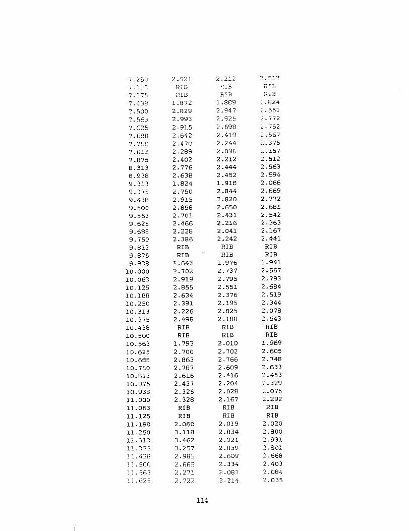
7.25O7.3137.3757.4387.5007.5637.6257.6887.7507.8137.8758.3138.9389.3139.3759.4389.5009.5639.6259.6889.7509.8139.8759.938
I0.00010.06910.12510.18810.25010.31310.37510.43810.50010.56310.62510.68810.75010.81310.87510.938ii.00011.06311.12511.18811.25011.313]_1.37511.43811.50011.56311.625
2.521RiBRIB
1.872
2.829
2.993
2.915
2.642
2.470
2.289
2.402
2.776
2.638
1.824
2.750
2.915
2.858
2.701
2.466
2.228
2.386
RIB
RIB
1.643
2.702
2.919
2.855
2.634
2.391
2.226
2. 498
RIB
RIB
1.793
2.700
2.863
2.787
2.616
2.437
2.325
2.328
RIB
RIB
2.060
3.118
3.462
3.257
2.985
2.665
2.271
2.722
2.212
RIB
1.889
2.947
2.925
2.698
2.419
2.244
2.096
2.212
2.444
2.452
1.918
2.844
2.820
2.650
2.431
2.216
2.041
2.242
RIB
RIB
1.976
2.737
2.795
2.551
2.376
2.195
2.025
2.188
RIB
RIB
2.010
2.702
2.766
2.609
2.416
2.204
2.028
2.167
RIB
RIB
2.019
2.834
2.921
2.839
2.609
2.334
2.083
2.214
2.517
RIB
RIB
1.824
2.551
2.772
2.752
2.567
2.375
2.157
2.512
2.563
2.594
2.066
2.669
2.772
2.681
2.542
2.363
2.167
2.441
RIB
RIB
1.941
2.567
2.793
2.684
2.519
2.344
2.078
2.543
RIB
RIB
1.969
2.605
2.748
2.633
2.453
2.329
2.075
2.292
RIB
RIB
2.020
2.8OO
2.93]
2.801
2.668
2.403
2.084
2.035
114

iN TURN
11.875 3.977 3.452 3.377
12.375 1.833 1.877 2.214
12.875 2.262 2.027 2.089
13.125 2.108 2.029 2.074
13.625 2.525 1.978 ].948
14.125 1.683 1.701 2.332
AFTER TURN
14.375 2.878 2.076 2.010
14.438 3.745 2.549 2.306
14.500 4.217 2.865 2.445
14.563 4.116 3.041 2.678
14.625 3.756 3.168 2.711
14.688 3.361 3.208 2.777
14.750 3.013 3.122 2.845
14.813 3.406 3.217 2.876
14.875 RIB RIB RIB
14.938 RIB RIB RIB
15.000 2.810 3.127 2.879
15.063 3.665 3.852 3.351
15.125 4.165 3.731 3.155
15.188 4.135 3.431 2.870
15.250 3.746 3.201 2.614
15.313 3.393 2.948 2.461
15.375 3.084 2.783 2.331
15.438 3.007 2.633 2.276
15.500 RIB RIB RIB
15.563 RIB RIB RIB
15.625 2.343 2.482 2.497
15.688 3.152 3.409 3.133
15.750 3.635 3.575 3.141
15.813 3.765 3.436 2.975
15.875 3.668 3.224 2.759
15.938 3.417 2.988 2.566
16.000 3.195 2.854 2.330
16-063 3.071 2.730 2.222
16.125 RIB RIB RIB
16.188 RIB RIB RIB
16.250 2.219 2.146 2.111
16.313 3.131 3.037 2.828
16.375 3.671 3.299 2.849
16.438 3.630 3.026 2.750
16.500 3.389 2.832 2.529
16.563 3.162 2.690 2.288
16-625 2.778 2.515 2.109
16.688 2.643 2.422 2.039
]7.063 9.421 3.031 2.786
115

17.688
18 125
18 188
18 250
18 313
18 375
18 438
18.500
18.563
18.625
18.688
18.750
18.813
18.875
18.938
19.000
19.063
19.125
19.188
19.563
20.188
20.813
21.438
22.063
22.688
23.313
23.938
24.375
24.438
24.500
24.563
24.625
24.688
24.750
24.813
24.875
24.938
25.000
25.063
25.125
25.188
25.250
25.313
25.375
25.438
25.500
25.563
25.625
25.688
25.750
25.813
3.336
1.651
2.594
3.104
3.1].3
2.978
2.703
2.49_0
2.358
RIB
RIB
1.728
2.872
3.048
3.119
2.951
2.763
2.602
2.468
2.917
2.872
2.913
2.762
2.622
2.690
2.716
2.680
1.776
2.979
3.320
3.268
3.073
2.830
2.601
2.495
RIB
RIB
2.022
1.756
1.960
2.070
2.053
2.297
2.299
2.268
RIB
RIB
3.188
3.786
2.544
]_.751
2.950
!.563
2.449
2.844
2.725
2.592
2.44q
2. 272
2 .14b
RIB
RIB
1.895
2.753
3. 106
2.833
2.611
2.457
2.367
2.192
2.915
2.857
2.821
2.813
2.804
2.710
2.714
2.740
2.073
2.919
3.458
3.288
2.938
2.518
2.217
2.042
RIB
RIB
1.847
1.653
1.922
2.021
1.936
2.049
2.018
2.099
RIB
RIB
3.049
4.248
2.278
1.945
2.942
1.887
2.764
3.080
2.908
2.569
2.239
2.032
].898
RIB
RIB
1.709
2.522
3.126
3.177
2. 979
2. 491
2.190
1.879
3.006
2.776
2.767
2.734
2.655
2.602
2.702
2.663
2.071
2.910
3.233
2.760
2.309
2.094
1.930
1.885
RIB
RIB
2.130
1.864
1.931
2.062
1.963
2.087
1.915
1.913
RIH
RIB
2.924
2.046
!.913
1.816
116

OUTER WALL AND INNER WALL
X/D I .L. C.L. I .L. c.m°
BEFORE TURN
OUTER WALL INNER WALL
0.188 2.215 2.634 2.283 3.182
0.250 2.243 2.858 2.676 3.868
0.313 2.329 3.186 2.937 3.766
0.375 2.262 2.938 2.893 3.685
0.438 2.511 3.161 2.781 3.529
0.500 2.580 3.338 2.656 3.425
0.563 2.640 3.467 2.783 3.332
0.625 2.574 3.075 2.661 3.224
0.688 2.880 3.269 3.153 3.137
0.750 2.825 3.022 3.233 3.040
0.813 2.929 2.977 3.222 2.820
0.875 2.978 2.853 3.187 2.661
0.938 2.999 2.798 3.267 2.528
1.000 2.932 2.706 3.032 2.417
1.063 2.906 2.522 3.058 2.339
1.125 2.888 2.546 3.002 2.416
1,188 2.790 2.556 2.898 2.337
1.250 2.734 2.465 2.830 2.327
1.313 2.614 2.475 2.812 2.281
1.375 2.577 2.304 2.646 2.292
1.438 2.514 2.278 2.629 2.130
1.500 2.465 2.258 2.610 2.062
1.563 2.414 2.196 2.546 2.034
1.625 2.340 2.176 2.553 2.059
2.063 2.127 2.098 1.973 1.869
2.688 1.813 1.944 1.727 1.666
3.313 1.768 1.846 1.640 1.698
3.938 1.664 1.734 1.605 1.677
4.563 1.663 1.712 1.732 1.689
5.188 1.644 1.671 1.661 1.592
5.813 1.681 1.663 1.659 1.621
6.438 1.723 1.675 1.660 1.627
6.813 1.651 1.558 1.786 1.701
6.875 1.654 1.564 1.782 1.664
6.938 1.650 1.594 1.738 1.705
7.000 1.615 1.587 1.718 1.670
7.063 1.587 1.525 1.744 1.671
7.125 1.641 1.544 1.699 1.652
7.188 ].640 ].621 1.752 1.667
117
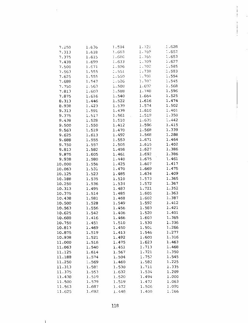
7.250
7.313
7.375
7.438
7. 500
7.563
7.625
7.688
7.750
7.813
7.875
8.313
8.938
9.313
9.375
9.438
9.500
9.563
9. 625
9. 688
9. 750
9.813
9.875
9.938
i0.000
10.063
10.125
10.188
10.250
10.313
10.375
10.438
10.500
10.563
10.625
i0. 688
10.750
10.813
10.875
10.938
ii .000
11.063
11.125
11.188
ii .250
11.313
11.375
ii .438
11.500
11.563
11.625
1 636
1 618
1 615
1 699
1 671
I 555
i 555
1 547
1 563
1.603
1.616
1.446
1.423
1. 591
1.517
i. 528
1.550
1.519
1.613
1.555
1.557
1.582
1.605
1.580
1.556
1.531
1.523
1.535
1.536
1.495
1.514
1. 581
1.528
1.556
1. 542
1.416
1.451
1.469
1.519
i. 521
1. 516
1. 540
1.614
1.574
!. 569
I. 581
1.553
1.519
1. 579
1.687
1. 692
1. 594
! .603
i. 600
1.633
1. 596
] 551
! 550
1 526
1 508
! 588
1 540
1.522
1. 539
1.439
1. 561
1.510
1.412
1.470
1.492
1.553
1.505
1.458
1.461
1.440
1.425
1.470
1. 485
1.510
1.534
1. 483
1. 485
i. 468
1. 549
1.456
1.406
1.466
1.510
1.450
1.413
1.492
1.475
1.451
1.567
1.504
1. 460
1.530
1.632
1. 520
1. 519
1.472
1. 448
1.721
1 769
1 765
1 709
i 702
1 738
1 70]
1 7017
1 692
1 748
1. 664
1.616
1.574
1.610
1. 519
1.635
1. 596
1. 568
1. 568
1.671
1.615
1.627
1. 692
1.675
i. 607
1.669
1.634
1.573
1.572
1.721
1.605
1.602
1.592
1.583
1.520
1. 603
1.530
1.501
1.546
1.600
1.623
1.713
1.721
1.752
1.582
1.711
1.534
1.494
1.472
1.506
i .400
! .628
1.652
1.653
1.627
I. 585
i. 583
i. 554
1.545
i. 568
1.596
1.525
1.474
1. 502
1.401
!. 350
1.442
! .415
1.339
!. 288
1.464
1.402
1.386
1.386
1.461
1.417
1.475
1.409
1.365
!. 367
i. 352
1.363
1.387
1.412
1.421
1.401
I. 365
1.336
1.266
1.277
1.316
1. 463
1. 468
i. 350
i. 545
1.225
1.335
1.209
1.000
1.063
1.090
! .266
118

11.875
12.375
12.875
13.125
13.625
14.125
14.375
14.438
14.500
14.563
14.625
14.688
14.750
14.813
14.875
14.938
15.000
15.063
15.125
15.188
15.250
15.313
15.375
15.438
15.500
15.563
15.625
15.688
15.750
15.813
15.875
15.938
16.000
16.063
16.125
16.188
16.250
16.313
16.375
16.438
16.500
16.563
16.625
16.688
17.063
2.116
2.075
2.872
2.364
2.393
2.306
2.383
2.475
2.433
2.474
2.479
2.466
2.433
2.477
2.359
2.399
2.349
2.446
2.478
2.533
2.627
2.541
2.518
2.576
2.555
2.543
2.427
2.459
2.471
2.467
2.417
2.410
2.297
2.256
2.248
2.315
2.152
2.170
2.159
2.125
2.164
2.130
2.148
2.173
2.039
IN TURN
1.671
2.267
2.708
2.418
2.472
2.416
AFTER TURN
2.292
2.288
2.258
2.250
2.382
2.339
2.354
2.392
2.339
2.382
2.339
2.370
2.487
2.473
2.554
2.482
2.481
2.447
2.452
2.424
2.380
2.468
2.434
2.420
2.383
2.353
2.303
2.335
2.284
2.285
2.243
2.239
2.235
2.996
2.206
2.337
2.177
2.162
2.032
2.366
2.143
2.182
2.213
2.376
2.485
2.561
2.712
2.824
2.849
2.682
2.570
2.607
2.605
2.582
2.558
2.527
2.619
2.630
2.650
2.669
2. 585
2. 593
2.654
2. 694
2.666
2.674
2.732
2.710
2.700
2.688
2.735
2.789
2.723
2.728
2.715
2.721
2.713
2.422
1.980
2.114
2.093
2.287
2.310
2.378
2.407
2.404
2.427
2.447
2.444
2.496
2.439
2.481
2.544
2.505
2.455
2.473
2.531
2.522
2.497
2.455
2.484
2.527
2.503
2.533
2.488
2.567
2.548
2.579
2.596
2.649
2.706
2.655
2.642
2.637
2.630
2.637
2.364
119

17.68819.12518.18818.25018.31318.37518.43818.50018.56318.62518.68818.75018.81318.87518.93819.00019.06319.12519.18819.56320.18820.81321.43822.06322.68823.31323.93824.37524.43824.50024.56324.62524.68824.75024.81324.87524.93825.00025.06325.12525.18825.25025.31325.37525.43825.50025.56325.62525.68825.75025.813
1.8641.8491.7741.8001.8171.8401.7951.8351.8181.8441.7611.7741.7261.7621.6801.6251.8051.7911.7701.6801.5711.7631.7791.8311.8371.5351.6111.8551.7911.7421.779
1.9861.8641.8401.840].8121.8731.8081.8281.8541.8161.8011.8001.7761.6801.7031.6521.6921.6811.7621.6511.5351.7171.7891.7311.8141.434i.&691.6411.6021.5821.629
2.2742.0862.0012.0651.9'701.9862.0571.9852.0111.9"161.8631.8511.8371.8501.8461.8551.8651.9391.8561.9531.8931.8091.7831.8301.7961.7291.6471.7691.8831. 9481.9361.9252.0221.9631.9842.0411.9461.9301.8641.7841.7901.7681.6981.7221.8011.9232.2772.7543.0771.3251.654
2.1712.0141.9831.9721.9171.9541.9431.8951.8501.8961.8271.8461.8381.9091.9051.8941.8871.8891.9091.943!.8491.7501.7131.6861.6581.6301.6011.7431.7251.6851.7131.6621.7291.7611.7601.7521.7431.6951.7951.7511.8221.8031.8752.0512.2322.1152.4503.0763.1131.8831.628
120

Rough Channel: Re--15,000, P/e---10,
Sh/Sh o
TOP WALL
e/D----0.063, o:- 00 °
X/D O.L. C.L. I .L.
BEFORE TURN
8.063 4.004 4.034 3.288
8.688 2.671 3.289 2.646
9.313 4.736 4.129 3.364
9.375 4.005 3.991 3.575
9.438 RIB 3.726 3.173
9.500 RIB 3.240 2.994
9.563 RIB RIB 2.837
9.625 2.802 RIB 2.554
9.688 4.373 RIB RIB
9.750 5.204 2.391 RIB
9.813 5.118 3.885 RIB
9.875 5.578 3.863 2.105
9.938 5.050 3.316 2.211
i0.000 3.172 3.567 2.872
10.063 RIB 3.629 2.924
10.125 RIB 3.043 2.810
10.188 RIB RIB 2.633
10.250 2.995 RIB 2.551
10.313 3.434 RIB RIB
10.375 5.655 2.159 RIB
10.438 6.496 3.264 RIB
10.500 5.108 3.701 1.992
10.563 4.202 3.720 2.564
10.625 2.923 3.294 2.896
10.688 RIB 3.055 2.793
10.750 RIB 2.693 2.617
10.813 RIB RIB 2.349
10.875 1.715 RIB 2.133
10.938 3.205 RIB RIB
ii.000 5.424 2.159 RIB
11.063 5.462 2.871 RIB
11.125 4.964 3.262 1.673
11.188 4.436 3.744 2.209
1].250 1.527 3.619 2.599
11.313 RIB 4.213 2.877
11.375 RIB 2.562 2.857
11.438 RIB RIB 2.878
11-500 1.135 RIB 2.879
11.563 4.481 RIB RIB
11.625 5.657 3.048 RIB
121

IN TURN
11.875 2.769 4.290 3.446
12.375 2.140 1.863 2.125
12.875 2.485 1.539 2.658
13.125 2.124 2.195 2.14]
13.625 2.170 2.108 1.956
14.125 2.474 2.228 2.165
AFTER TURN
14.375 1.895 2.511 RIB
14.438 1.463 RIB RIB
14.500 3.171 RIB 1.969
14.563 RIB RIB 1.988
14.625 RIB 2.414 2.058
14.688 RIB 2.762 2.929
14.750 2.984 3.942 3.103
14.813 3.016 4.140 3.413
14.875 3.923 4.307 3.393
14.938 4.193 4.000 RIB
15.000 4.266 4.063 RIB
15.063 4.123 RIB RIB
15.125 4.113 RIB 1.938
15.188 RIB RIB 2.764
15.250 RIB 1.631 2.898
15.313 RIB 2.625 3.063
15.375 1.884 3.257 3.053
15.438 3.369 3.476 2.794
15.500 3.516 3.290 2.586
15.563 3.516 3.124 RIB
15.625 3.308 2.999 RIB
15.688 3.235 RIB RIB
15.750 3.005 RIB 1.727
15.813 RIB RIB 2.874
15.875 RIB 1.207 2.842
15.938 RIB 2.828 3.135
16.000 1.703 3.017 3.271
16.063 2.646 3.153 3.125
16.125 3.276 2.986 2.674
16.188 3.350 2.838 RIB
16.250 3.414 2.985 RIB
16.313 3.340 RIB RIB
16.375 3.191 RIB 1.353
16.438 RIB RIB 2.416
16.500 RIB 1.314 3.238
16.563 RIB 2.432 3.037
16.625 1.719 2.822 2.95_
16.688 2.554 2.811 2.444
17.313 2.018 2.736 3.101
]7.938 2.784 3.196 3.197
122

OUTER WALL AND INNER WALL
X/D I .L. C.L. I .L. C.L.
BEFORE TURN
OUTER WALL INNER WALL
8.063 2.590 2.243 2.744 1.965
8.688 3.074 2.677 2.371 1.963
9.375 2.700 2.925 2.096 1.801
9.500 2.830 2.991 2.716 1.956
9.625 2.770 2.014 2.280 1.901
9.750 2.594 1.966 2.213 1.687
9.875 2.502 2.316 1.862 1.484
i0.000 2.609 2.067 2.004 1.523
i0.125 2.444 2.060 2.534 1.855
10.250 2.406 2.054 2.373 1.894
10.375 2.378 2.214 2.307 1.599
10.500 2.755 2.155 2.084 1.346
10.625 2.362 2.074 1.985 1.623
10.750 2.313 2.233 1.774 1.869
10.875 2.348 2.226 2.237 1.845
ii.000 2.217 2.281 1.995 2.099
11.125 2.188 2.252 1.960 1.765
11.250 2.313 2.162 2.335 1.812
11.375 2.459 2.114 2.771 2.075
11.500 1.880 2.179 3.238 2.133
11.625 2.621 2.122
123

11.875
12.375
12.875
13.125
13.625
14.125
14.375
14.500
14.625
14.750
14.875
15.000
15.125
15.250
15.375
15.500
15.625
15.750
15.875
16.000
16.125
16.250
16.375
16.500
16.625
17.313
17.938
2.606
2.705
3.490
3.419
2.667
2.522
2.209
2.128
2.324
2.419
2.413
2.407
2.431
1.977
2.114
1.992
1.953
2.205
2.374
2.251
2.380
2.341
2.301
2.197
2.210
2.376
1.867
IN TURN
2.095
3. 306
2.983
2.859
2. 493
2.466
AFTER TURN
2.182
2.224
2.051
2.105
1.964
1.957
2.186
1.908
i .838
1.819
2.009
1.990
1.887
1.888
1.870
1.861
1.789
1.895
1.907
2.134
2.055
2.904
2.595
2.655
3.016
3.131
3.245
2.954
3.037
2.819
2.819
3.131
3.234
3.151
2.910
2.762
2.644
2.442
2.545
2.004
2.211
2.804
2.812
2.945
3.049
3.505
3.557
3.723
3.879
3.737
3.686
3.707
3.613
3.163
2.965
2.922
3.269
3.162
2.759
2.157
2.312
124

Rough Cllannel Re=-:30,000, P/e:=10, e/D--0.063, ¢_--00 °
Sh/Sh o
TOP WALl.
x/D o.L. C.L. I .1,.
.375
.438
.500
• 563
.625
.688
.750
.000
.063
.125
.188
.250
.313
.375
.813
.438
.063
.688
.313
.938
•563
• 188
.625
.688
.750
.813
.875
.938
.000
.250
.313
.375
.438
.500
.563
.625
.063
.688
.313
BEFORE TURN
1.767
2.974
4.108
2.547
2.245
1.701
2.114
3.406
3.828
4.281
4.859
4.310
4.071
3.853
4.265
4.143
4.044
3.869
3.576
3.395
3.390
3.460
3.029
3.615
3.807
3.677
3.564
3.293
2.791
3.505
3.731
3.915
3.820
3.413
3.197
2.930
3.649
3.712
4.1773.982 3.035
125
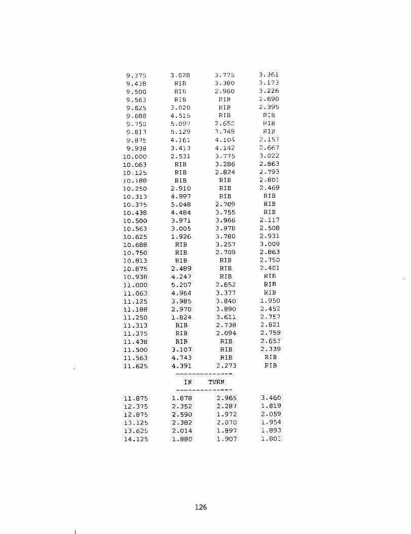
9.3759.4389.5009. 5639.6259. 6889.7509.8139.8759.938
i0.00010.O6310.12510.18810.25010.31310.37510.43810.50010.56310.62510.68810.750i0.813i0.875i0.938ii.00011.06311.12511.18811.25011.31311.37511.43811.50011.56311.625
11.87512.37512.87513.12513.62514.125
3.028RIBRIBRIB
345543
3.7753.3802.960RIB
020 RIB
515 RIB
097 2.650
129 3.748
161 4.104
413 4.142
2.531 3.775
RIB 3.286
RIB 2.824
RIB RIB
2.910 RIB
4.997 RIB
5.048 2.709
4.484 3.755
3.971 3.966
3.005 3.978
1.926 3.780
RIB 3.257
RIB 2.709
RIB RIB
2.489 RIB
4.247 RIB
5.207 2.652
4.964 3.377
3.985 3.840
2.970 3.890
1.824 3.611
RIB 2.738
RIB 2.094
RIB RIB
3.107 RIB
4.743 RIB
4.391 2.273
IN TURN
1.878
2.352
2.590
2.382
2.014
1.880
2.965
2.287
1.972
2.070
1.897
1.907
3.361
3.173
3.226
2.690
2.395
RIB
RIB
RIB
2.157
2.667
3.022
2.863
2.793
2.801
2.469
RIB
RIB
RIB
2.117
2.508
2.931
3.009
2.863
2.750
2.40]
RIB
RIB
RIB
1.950
2.452
2.757
2.821
2.759
2.653
2.339
RIB
RIB
3.460
1.819
2.059
1.954
1.893
1.80Z
126

AFTER TURN
14.375 1.736 1.527 RIB
14.438 1.342 RIB RIB
14.500 1.788 RIB 1.597
14.563 RIB RIB 1.942
14.625 RIB 2.023 2.306
14.688 RIB 3.191 2.419
14.750 2.121 3.621 2.620
14.813 3.369 3.761 2.905
14.875 3.522 3.724 2.980
14.938 3.725 3.800 RIB
15.000 3.712 3.591 RIB
15.063 3.610 RIB RIB
15.125 3.456 RIB 2.136
15.188 RIB RIB 2.695
15.250 RIB 2.178 2.751
15.313 RIB 3.535 2.660
15.375 2.188 3.637 2.595
15.438 3.357 3.669 2.460
15.500 3.619 3.471 2.408
15.563 3.433 3.029 RIB
15.625 3.458 2.797 RIB
15.688 2.950 RIB RIB
15.750 2.897 RIB 1.913
15.813 RIB RIB 2.682
15.875 RIB 1.440 2.989
15.938 RIB 2.532 3.045
16.000 1.649 3.116 2.858
16.063 2.652 3.212 2.605
16.125 2.851 2.953 2.320
16.188 2.947 2.972 RIB
16.250 2.803 2.699 RIB
16.313 2.634 RIB RIB
16.375 2.541 RIB 1.996
16.438 RIB RIB 2.991
16.500 RIB 1.500 2.996
16.563 RIB 2.619 2.716
16.625 1.750 3.053 2.533
16.688 2.449 2.857 2.233
17.313 3.199
17.938 2.703
18.375 2.603
18.438 3.980
18.500 4.110
18.563 4.072
18.625 3.801
18-688 3.524
18.750 2.437
19.000 2.758
127
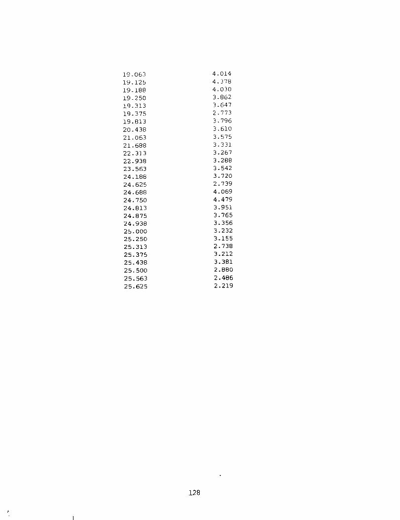
19.063
19.125
19.188
19.250
19.313
19.375
19.813
20.438
21.063
21.688
22.313
22.938
23.563
24.188
24.625
24.688
24.750
24.813
24.875
24.938
25.000
25.250
25.313
25.375
25.438
25.500
25.563
25.625
4.014
4.378
4.030
3.862
3.647
2.773
3.796
3.610
3.575
3.331
3.267
3.288
3.542
3.720
2.739
4.069
4.479
3.951
3.765
3.356
3.232
3.155
2.738
3.212
3.381
2.880
2.486
2.219
128
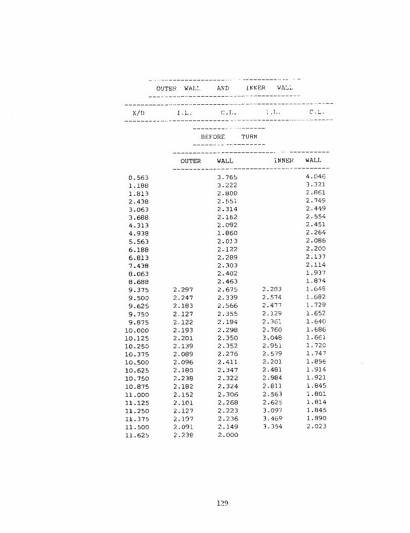
OUTERWALL AND INNER WALL
X/D I-L. C.L. _.L. C L.
BEFORE TURN
OUTER WALL INNER WALL
0.563 3.765 4.0461.188 3.222 3.3211.813 2.800 2.8612.438 2.551 2.7493.063 2.314 2.4493.688 2.162 2.5544.313 2.092 2.4514.938 1.860 2.2645.563 2.013 2.0866.188 2.122 2.2006.813 2.289 2_1377.438 2.303 2.1148.063 2.402 1.9378.688 2.463 1.8749.375 2.297 2.675 2.283 1.6499.500 2.247 2.339 2.574 1.6829.625 2.183 2.566 2.477 1.7299.750 2.127 2.355 2.129 1.6529.875 2.122 2.194 2.361 1.640
i0.000 2.193 2.298 2.760 1.68610.125 2.201 2.350 3.048 1.66110.250 2.139 2.352 2.951 1.72010.375 2.089 2.276 2.579 1.74710.500 2.096 2.411 2.201 1.85610.625 2.180 2.347 2.481 1.91410.750 2.238 2.322 2.984 1.92110.875 2.182 2.324 2.811 1.845ii.000 2.152 2.306 2.563 1.80111.125 2.101 2.268 2.625 1.81411.250 2.127 2.223 3.097 1.84511.375 2.197 2.236 3.469 1.89011.500 2.091 2.149 3.354 2.02311.625 2.238 2.000
129

11.87512.37512.87513.12513.62514.125
14.37514.50014.62514.75014.87515.00015.12515.25015.37515.50015.62515.75015.87516.00016.12516.25016.37516.50016.62517.31317.93818.56319.18819.81320.43821.06321.68822.31322.93823.56324.18824.81325.438
2.3992.2002.9932.3492.3762.617
2.6942.7752.6042.4902.3012.1051.8871.9562.0572.1472.1972.2862.3432.3492.2842.2642.2892.3462.248
IN TURN
2.1032.4492.5732.0402.4052.241
AFTER TURN
2.2952.1741.9962.0141.9761.8741.8351.8331.8511.9151.9011.9831.9622.OOO2.0772.0762.0482.0602.0912.5322.5952.5292.3102.3581.9221.9161.9342.1482.2732.3772.376
2.9953.0923.2603.2023.2192.9932.8812.7692.5362.5OO2.4632.4392.3582.4052.3882.4932.6242.627
3.0723.O8O3.0333.0703.0423.1543.1562.9112.7802.6872.6312.5372.5202.4972.4222.2552.4762.8872.6662.7082.5762.5122.397
2.111
2.151
2.105
2.089
2.326
2.563
2.622
2.852
3.390
130

Rough Channel Re---60,000, P/e=10, e/D--0.063, (t'--60"
TOP WALL
X/D O.L- C.L. I .L.
BEFORE TURN
9.313 3.522 3.871 3.413
9.375 2.614 3.512 3.247
9.438 RIB 3.342 3.093
9.500 RIB 3.022 2.889
9.563 RIB RIB 2.747
9.625 2.813 RIB 2.567
9.688 3.992 RIB RIB
9.750 4.465 2.190 RIB
9.813 4.276 3.421 RIB
9.875 3.719 3.717 1.948
9.938 3.142 9.574 2.382
i0.000 2.095 3.290 2.609
10.063 RIB 3.021 2.609
10.125 RIB 2.692 2.495
10.188 RIB RIB 2.443
10.250 3.052 RIB 2.382
10.313 4.394 RIB RIB
10.375 4.447 2.524 RIB
10.438 4.019 2.978 RIB
10.500 3.316 3.672 2.072
10.563 2.595 3.881 2.671
10.625 1.826 3.697 2.880
10.688 RIB 3.270 2.945
10.750 RIB 2.712 2.915
10.813 RIB RIB 2.771
10.875 2.628 RIB 2.719
10.938 4.089 RIB RIB
ii.000 4.233 2.555 RIB
11.063 3.671 2.915 RIB
11.125 2.834 3.669 1.816
11.188 2.085 3.649 2.471
11.250 1.802 3.210 2.683
11.313 RIB 2.689 2.853
11.375 RIB 2.067 2.835
11.438 RIB RIB 2.583
11.500 2.874 RIB 2.335
11.563 4.159 RIB RIB
11.625 3.719 2.625 RIB
131

IN TURN
11.875 1.732 2.649 3.340
12.375 1.631 1.680 ].'120
12.875 1.927 1.728 1.987
19.125 1.794 1.785 1.902
13.625 1.669 1.910 2.071
14.125 1.907 2.221 2.265
14.375
14.438
14.500
14.563
14.625
14.688
14.750
14.813
14.875
14.938
15.000
15.063
15.125
15.188
15.250
15.313
15.375
15.438
15.500
15.563
15.625
15.688
15.750
15.813
15.875
15.938
16.000
16.063
16.125
16.188
16.250
16.313
16.375
16.438
16.500
16.563
16.625
16.688
AFTER TURN
1.702
1.531
2.438
RIB
RIB
RIB
2.352
2.873
3.362
3.506
3.529
3.389
3.199
RIB
RIB
RIB
2.566
3.397
3.394
3.280
3.169
2.985
2.805
RIB
RIB
RIB
2.012
2.637
2.917
2.898
2.844
2.670
2.599
RIB
RIB
RIB
2.179
2.781
2.209
RIB
RIB
RIB
2.287
2.928
3.151
3.299
3.299
3.182
3.065
RIB
RIB
RIB
2.675
3.440
3.600
3.498
3.220
3.083
2.789
RIB
RIB
RIB
1.817
2.874
2.969
2.908
2.827
2.631
2.526
RIB
RIB
RIB
2.226
2.958
3.015
3.096
RIB
RIB
2.355
2.554
2.599
2.673
2.696
2.646
2.684
RIB
RIB
RIB
2.531
3.009
3.008
2.878
2.753
2.639
2.547
RIB
RIB
RIB
1.967
2.674
2.815
2.761
2.618
2.419
2.245
RIB
RIB
RIB
2.719
3.269
3.215
2.960
2.569
2.503
132

OUTERWALL AND INNER WALL
X/D I.L- C.L. I.L. C.L.
BEFORE TURN
OUTER WALL INNER WALL
9.375 2.070 2.983 2.191 1.6829.500 2.004 2.596 2.575 1.6709.625 1.926 2.075 2.504 1.6349.750 1.880 2.159 2.237 1.6229.875 1.918 2.177 2.208 1.590
i0.000 1.932 2.142 2.413 1.64310.125 1.939 2.137 2.595 1.63810.250 1.916 2.148 2.566 1.61810.375 1.881 2.109 2.308 1.72110.500 1.918 2.108 2.085 1.74210.625 1.936 2.083 2.128 1.74010.750 1.905 2.063 2.434 1.71610.875 1.863 2.013 2.512 1.696ii.000 1.843 2.009 2.328 1.65711.125 1.835 1.924 2.144 1.67111.250 1.788 1.885 2.482 1.70711.375 1.788 1.813 2.849 1.71011.500 1.761 1.805 2.881 1.74311.625 1.803 1.779
133

IN q'l]l_N
11.875
12.375
12.875
13.125
13.625
14.125
1.98"7
2.232
2.566
2.426
2.171
2.696
1.773
2.776
2.228
1.998
2.100
2.158
AFTER TURN
14
14
14
14
14
15
15
15
15
15
15
15
15
16
16
16
16
16
16
.375
.500
.625
.750
.875
.000
.125
.250
.375
.500
.625
.750
.875
.000
.125
.250
.375
.500
.625
.528
.653
.624
.543
.485
.404
.352
.365
.549
.625
.650
.636
•603
.490
.350
.301
.302
.218
.030
1.975
1. 968
2.040
2.041
2.047
2.094
2.113
2.221
2.234
2. 362
2. 368
2.400
2.378
2.337
2. 301
2.267
2.241
2.196
2.170
2.486
2.587
2.685
2.686
2.724
2.751
2.754
2.751
2.718
2.673
2.569
2.518
2.434
2.357
2.376
2.275
2.266
2.176
1.830
2.077
2.171
2.356
2.489
2.557
2.518
2.621
2.577
2.523
2.511
2.503
2.457
2.369
2.314
2.305
2.274
2.157
134

Roll qll Channel: Re==15,000, P/e_10, e/D=0.063, _'--_]5 _'
TOP WALL
X/D O.I,. C.L- I .L.
BEFORE TURN
8.875 2.150 3.253 1.848
8.938 3.974 4.462 RIB
9.000 1.544 4.184 RIB
9.063 RIB 3.619 2.739
9.125 RIB 2.443 2.849
9.188 4.958 2.706 2.448
9.250 6.088 2.233 2.306
9.313 6.454 RIB 2.327
9.375 4.465 RIB 2.231
9.438 3.302 2.124 2.117
9.500 2.705 2.671 1.968
9.563 2.261 4.512 RIB
9.625 1.810 3.960 RIB
9-688 RIB 3.017 2.734
9.750 RIB 2.565 2.541
9.813 5.757 2.443 2.303
9.875 6.855 RIB 2.225
9.938 6.631 RIB 2.219
i0.000 5.114 RIB 2.274
10.063 3.547 2.240 1.737
10.125 2.258 3.576 1.643
10.188 2.039 4.460 RIB
10.250 1.751 4.117 RIB
10.313 RIB 3.140 2.842
10.375 RIB 1.953 2.210
10.438 4.899 2.079 2.046
10.500 6.040 1.317 2.267
10.563 5.424 RIB 2.243
10.625 4.345 RIB 1.904
10.688 3.514 2.176 2.117
10.750 2.960 2.939 1.848
10.813 1.882 4.356 RIB
10.875 1.257 4.199 RIB
10.938 RIB 3.459 2.458
ii.O00 RIB 2.276 2.565
11.063 4.808 1.722 2.341
11.125 5.763 1.698 2.978
11.188 5.718 RIB 3.856
]1.250 4.530 RIB 3.354
]35

11.313
11.975
ii.438
ll.500
i1.563
11.625
3.646
2. 868
2.472
2. 190
1.959
1.954
2.548
2.879
4.33[?
4.126
3.316
2.688
3.06]
2.64"1
RIB
Ri B
1.860
2.173
IN TURN
i1.875 2.120 2.195 1.935
12.375 2.179 2.411 2.139
12.875 2.639 2.434 2.180
13.125 2.543 2.415 2.292
13.625 2.651 2.141 2.151
14.125 2.319 2.321 2.117
AFTER TURN
14.375 2.518 2.310 2.230
14.438 2.525 2.307 2.202
14.500 2.453 2.089 RIB
14.563 2.451 2.656 RIB
14.625 2.310 3.598 2.220
14.688 2.022 2.254 3.283
14.750 1.751 RIB 2.770
14.813 1.201 RIB 3.080
14.875 2.544 2.273 3.609
14.938 1.437 1.862 3.956
15.000 RIB 2.225 4.182
15.063 RIB 2.763 4.007
15.125 2.326 3.214 RIB
15.188 2.114 3.736 RIB
15.250 2.697 4.549 2.719
15.313 3.588 4.943 2.184
15.375 4.026 RIB 2.480
15.438 4.455 RIB 2.907
15.500 4.622 3.215 3.432
15.563 4.790 3.012 3.713
15.625 RIB 3.503 3.669
15.688 RIB 3.978 2.857
15.750 2.832 3.968 RIB
15.813 2.839 3.790 RIB
15.875 3.597 3.710 1.463
15.938 4.348 3.267 2.097
16.000 4.446 RIB 2.785
16.063 4.428 RIB 3.209
16.125 3.966 2.535 3.261
16.188 3.593 2.720 2.975
16.250 RIB 3.011 2.938
16.313 RIB 3.276 2.393
16.375 1.565 3.105 RIB
136

16.438
15.500
16.563
16.625
16.688
16.750
16.813
16.875
16.938
17.000
17.063
17.125
1.722
2.665
3.486
3.816
3.896
3.590
2.053
RIB
RIB
RIB
1.879
2.534
3.495
3.351
1.553
RIB
RIB
1.121
1.746
2.731
3.044
3.222
3.175
3.055
RIB
2.411
2.759
3.078
3.130
2.859
2.723
2.532
2.457
RIB
RIB
2.476
137

OUTER WALL AND INNER WALL
X/D I .L. C.L. I .L. C.L-
BEFORE TURN
OUTER WALL INNER WALL
8.875 1.903 2.069 2.270 1.950
9.000 1.918 2.129 2.555 2.020
9.125 1.943 2.109 2.497 1.918
9.250 1.922 2.132 2.421 1.879
9.375 2.017 2.165 2.506 1.822
9.500 1.987 2.143 2.627 1.757
9.625 1.949 2.149 2.266 1.826
9.750 1.991 2.155 2.307 1.796
9.875 1.987 2.249 2.658 1.820
i0.000 1.922 2.343 2.494 1.844
10.125 1.884 2.391 2.542 1.893
10.250 1.898 2.405 2.838 1.917
10.375 1.975 2.340 3.035 1.940
10.500 2.024 2.204 2.897 2.007
10.625 1.907 2.121 2.769 2.012
10.750 1.947 2.091 3.026 2.017
10.875 1.892 2.123 3.108 2.066
Ii. OO0 1.880 2.093 3.068 2.089
11.125 1.825 2.107 3.375 1.990
11.250 1.710 2.035 3.447 1.926
11.375 1.664 1.980 3.155 1.940
11.500 1.627 1.666 3.141 1.859
11.625 1.659 1.543
138

11.87512.37512.87513.12513.62514.125
14.37514.50014.62514.75014.87515.00015.12515.25015.37515.50015.62515.75015.87516.00016.12516.25016.37516.50016.62516.75016.87517.00017.125
1.9352.4352.8542.8942.4952.760
2.6502.7432.7242.6702.5812.3442.1671.8841.7671.6751.7862.2322.6002.7222.7742.8082.7162.6872.5602.4592.4022.4882.269
IN TURN
1.6402.7072.7092.2092.3613.040
AFTER TURN
3.1142.9572.9472.8592.7362.5172.2701.9871.9141.8051.8461.8241.9351.9942.0972.1652.2422.3372.4062.5462.5532.5772.547
2.9623.0753.1723.2423.3053.2723.2213.1092.9172.8132.6812.6732.5142.5412.4702.6742.6563.2563.0422.9172.9983.197
2.9642.9823.0873.3143.2373.1603.1883.2773.0863.0092.7712.7362.5072.4802.6052.6762.7742.8462.9012.7662.8562.991
139

Rough Channel Re--30,000, P/e--10, e/D---0.063, _- 45"
TOP WALL
X/D O.L. C.L. I .h.
BEFORE TURN
0.625 1.609
0.688 3.180
0.750 4.713
0.813 4.237
0.875 3.835
0.938 3.459
1.000 2.919
1.063 3.247
1.250 1.849
1.313 2.604
1.375 3.197
1.438 3.676
1.500 3.370
1-563 3.002
1.625 2.799
1.688 2.733
2.125 2.706
2.750 2.550
3.375 2.535
4.000 2.475
4.625 2.416
5.250 2.320
5.875 2.147
6.250 1.886
6.313 3.014
6.375 2.750
6.438 2.579
6.500 2.358
6.563 2.153
6.625 1.896
6.688 1.910
6.875 1.758
6.938 3.074
7.000 2.705
7.063 2.520
7.125 2.267
7.188 2.109
7.250 1.963
7.313 1.912
140

7.750
_.375
8.875
8.938
9.000
9.063
9.125
9.188
9.250
9.313
9.375
9.438
9. 500
9.563
9.625
9.688
9.750
9.813
9.875
9.938
!0.000
10.063
10.125
i0. 188
10.250
10.313
10.375
10.438
i0. 500
i0. 563
10.625
10.688
10.750
10.813
I0.875
i0.938
ii.000
ii .063
11.125
11.188
Ii .250
11.313
11.375
11.438
11.500
ii. 563
ii .625
2.375
1.461
1. 308
RIB
RIB
4.483
4.321
5.166
4.289
3.442
2. 664
1.758
1.781
RIB
RIB
3.892
3. 862
4.751
3.865
3.043
2.306
1.719
1.771
RIB
RIB
4.784
4.832
4.784
3.761
3.064
2. 391
2.089
1.703
RIB
RIB
4.035
4.328
4.538
3.659
3.119
2.618
2.474
2. 369
2.507
2. 496
2.296
2.400
2.892
3.882
3.634
3.106
2.319
1. 666
1.501
RIB
RIB
1.692
2.207
3.792
3.775
3. 387
2.755
2.021
2.112
RIB
RIB
1.859
i .848
3.430
3.520
3. 164
2. 566
1.924
1.930
RIB
RIB
2.329
2.339
4.096
4.016
3.473
2.820
2.524
2.145
RIB
RIB
2.313
2.873
3.997
3. 686
3.204
2.550
1.786
RIB
RIB
2.473
2.531
2.594
2.634
2. 726
2. 469
2.189
1.686
RIB
RIB
1.905
2.521
2.282
2.600
2.963
2.860
2.639
2.356
RIB
RIB
2.367
2. 368
2.187
2.491
2.828
2.710
2.630
2.143
RIB
RIB
2. 607
2.869
2. 668
3.330
3. 602
3. 468
3.367
2.800
RIB
RIB
2.129
2.616
141

IN TURN
11.875 2.562 2.658 2.379
12.375 2.359 2.477 2.460
12.875 2.718 2.562 2.590
13.125 2.731 2.652 2.707
13.625 2.476 2.459 2.661
14.125 2.860 2.835 2.833
AFTER TURN
14.375 2.965 2.889 2.939
14.438 3.187 2.939 3.831
14.500 3.182 2.868 RIB
14.563 3.166 3.627 RIB
14.625 2.601 5.242 2.719
14.688 2.180 5.279 3.392
14.750 2.057 RIB 3.143
14.813 1.967 RIB 3.410
14.875 2.535 1.740 3.884
14.938 4.609 2.062 4.309
15.O00 RIB 2.246 4.535
15.O63 RIB 2.983 4.229
15.125 3.228 3.553 RIB
15.188 3.324 3.840 RIB
15.250 3.622 4.479 3.388
15.313 4.448 4.841 3.368
15.375 4.523 RIB 3.206
15.438 4.609 RIB 3.263
15.500 4.764 3.123 3.607
15.563 4.930 3.338 3.660
15.625 RIB 3.570 3.650
15.688 RIB 3.830 2.844
15.750 2.786 3.820 RIB
15.813 2.730 3.781 RIB
15.875 3.929 3.743 2.624
15.938 4.514 3.507 2.959
16.000 4.499 RIB 3.447
16.063 4.251 RIB 3.448
16.125 3.924 2.835 3.471
16.188 3.562 2.977 3.137
16.250 RIB 3.296 3.132
16.313 RIB 3.718 2.825
16.375 2.635 3.724 RIB
16.438 2.732 3.811 RIB
16.500 3.548 3.623 2.580
16.563 4.150 3.505 2.814
16.625 4.123 RIB 3.021
16-688 3.998 RIB 2.918
16.750 3.816 1.972 2.706
i_2

16.813
16.875
16.938
]7.OOO
17.063
17.125
17.625
18.250
18.688
18.750
18.813
18.875
18.938
19.000
19.O63
19.125
19.313
19.375
19.438
19.500
19.563
19.625
19.688
19.750
20.125
20.750
21.375
22.000
22.625
23.250
23.875
24.313
24.375
24.438
24.500
24.563
24.625
24.688
24.750
24.938
25.000
25.063
25.125
25.188
25.250
25.313
25.375
3- 622
RIB
RIB
] .675
I .920
2. 547
2.155
2.791
2.9"75
2.997
2.813
2.796
3.092
3.295
1.894
2.368
3.378
2.663
2.376
2.247
2.085
2.026
1. 744
2.572
3.430
3.020
2.649
2.443
2.212
2.031
2.835
2.725
2.568
2.552
2.491
2.400
2.511
1.908
2.667
3.480
2.979
2.704
2.318
2.058
2.017
1.816
2.O41
3.219
2.577
2.076
1.925
1.910
2.279
2.442
2.327
2.275
R I B
RIB
2.002
143

OUTER WALL AN[) ] NNE}< WAll,
X/D I .L. C.L. I .L. C.L.
BEFORE TURN
OUTER WALL INNER WALL
0.875 2.904 2.717
1.500 2.255 2.195
2.125 2.020 1.959
2.750 1.898 2.011
3.375 1.793 1.964
4.000 1.661 1.967
4.625 1.605 1.889
5.250 1.528 2.004
5.875 1.599 1.982
6.500 1.538 2.002
7.125 1.489 1.811
7.750 1.464 1.829
8.375 1.829 1.700
8.875 1.891 2.135 2.011 1.470
9.000 1.890 2.214 1.980 1.583
9.125 1.951 2.160 1.971 1.501
9.250 1.955 2.169 1.934 1.676
9.375 2.016 2.144 2.125 1.639
9.500 2.060 2.164 2.150 1.573
9.625 1.915 2.139 1.895 1.656
9.750 1.982 2.177 2.092 1.580
9.875 1.991 2.169 2.167 1.582
i0.000 1.886 2.155 2.004 1.579
10.125 1.946 2.186 2.029 1.571
10.250 1.921 2.223 2.070 1.590
10.375 1.970 2.029 2.202 1.689
10.500 1.984 2.195 2.096 1.759
10.625 1.954 2.169 2.047 1.756
10.750 2.029 2.116 2.379 1.724
10.875 1.932 2.029 2.548 1.782
ii.000 1.952 2.049 2.627 1.779
11.125 1.928 2.063 2.873 1.837
11.250 1.870 2.017 2.951 1.934
11.375 1.990 2.020 2.851 1.953
11.500 2.049 1.929 2.896 2.110
11.625 2.068 1.910 2.260 2.172
144

ii .875
12.375
12.875
13.125
13.625
14. 125
14.375
14.500
14. 625
14.750
14.875
15.000
15.125
15.250
15.375
15.500
15.625
15.750
15.875
16.000
16.125
16.250
16.375
16.500
16.625
16.750
16.875
17.000
17.125
17.625
18.250
18.875
19.500
20.125
20.750
21.375
22.000
22.625
23.250
23.875
24.500
25.125
2.163
2.281
2.155
1.729
2.220
2.831
2.507
2.229
2.145
2.178
2.054
1.924
1.761
1.680
1.757
1.756
2.013
2.181
2.276
2.304
2.388
2.365
2.301
2.294
2.327
2.274
2.261
2.259
2.240
]N THRN
i .916
2.604
2.076
1.891
2.242
2.968
AFTER TURN
2.698
2.682
2.459
2.465
2.542
2.374
2.239
2.188
2.238
2.260
2.175
2.213
2.302
2.268
2.233
2.215
2.293
2.377
2.291
2.375
2.391
2.447
2.382
2.048
1.868
1.705
1.553
1.359
1.512
1.663
1.575
1.575
1.469
1.462
1.592
2.733
2.537
2.778
2.982
2.995
3.033
3.109
3.062
2.938
2.907
2.771
2.784
2.640
2.564
2.487
2.427
2.389
2.283
2.291
2.218
2.197
2.197
2.158
2.736
2.529
2.576
2.768
2.915
2.880
2.983
2.981
2.991
2.989
2.875
2.805
2.711
2.607
2.564
2.550
2.398
2.360
2.288
2.147
2.142
2.161
2.110
2.345
2.OO81.891
1.806
1.680
1.635
1.571
1.530
1.597
1.588
1.611
1.726
2.434
145

Rough Channel: Re----60,000, P/e--10, e/D----0.063, a'- 45 °
TOP WALL
×/D o.L. c.L. I.L.
BEFORE TURN
8.875 2.650 2.902 1.722
8.938 2.854 3.341 RIB
9.000 2.590 2.842 RIB
9.063 RIB 2.297 2.200
9.125 RIB 1.664 2.211
9.188 4.133 2.459 2.273
9.250 4.253 2.232 2.412
9.313 4.341 RIB 2.341
9.375 2.846 RIB 2.175
9.438 2.105 2.482 1.899
9.500 1.464 3.053 1.620
9.563 1.104 3.216 RIB
9.625 0.9461 2.898 RIB
9.688 RIB 2.251 2.253
9.750 RIB 1.888 2.194
9.813 3.947 1.596 2.276
9.875 3.455 1.445 2.464
9.938 3.317 RIB 2.454
i0.000 2.609 RIB 2.334
10.063 2.039 1.903 2.134
10.125 1.536 3.142 1.867
10.188 2.040 3.008 RIB
10.250 1.862 2.524 RIB
10.313 RIB 2.054 2.221
10.375 RIB 1.540 1.928
10.438 4.182 1.769 2.167
10.500 4.250 1.630 2.297
10.563 3.644 RIB 2.175
10.625 2.780 RIB 1.896
10.688 2.110 2.548 1.869
10.750 1.681 2.521 1.538
10.813 2.006 3.110 RIB
10.875 1.683 2.720 RIB
10.938 RIB 2.125 1.451
ii.000 RIB 1.583 1.773
11.063 3.610 1.737 1.847
11.125 3.741 1.627 2.265
11.188 3.189 RIB 2.231
11.250 2.360 RIB 2.034
146

11.313
11.375
11.438
i1.500
11.563
11.625
1.862
1.578
1.521
1.484
1.579
1.542
1.732
2.464
2.679
2.102
1.605
1.399
IN TURN
1.983
1.766
RIB
BIB
1.334
1.525
11.875 1.724 1.514 1.452
12.375 1.613 1.824 1.680
12.875 1.860 1.767 1.708
13.125 1.816 1.723 1.814
13.625 1.736 1.663 1.775
14.125 2.067 1.722 1-88 a
AFTER TURN
14.375 1.891 1.675 2.302
14.438 1.959 1.587 1.903
14.500 1.895 1.516 RIB
14.563 1.794 1.858 RIB
14.625 1.713 3.398 1.816
14.688 1.514 3.045 2.200
14.750 1.384 RIB 1.911
14.813 1.754 RIB 2.025
14.875 2.319 1.529 2.406
14.938 3.456 1.980 3.018
15.000 RIB 2.177 3.571
15.063 RIB 2.500 2.996
15.125 2.066 2.914 RIB
15.188 2.337 3.427 RIB
15.250 2.891 3.783 1.750
15.313 3.733 2.876 2.308
15.375 4.083 RIB 2.566
15.438 4.179 RIB 2.618
15.500 4.243 1.667 2.681
15.563 3.823 2.388 2.709
15.625 RIB 2.601 2.673
15.688 RIB 2.727 2.311
15.750 2.314 2.811 RIB
15.813 2.728 2.930 RIB
15.875 3.586 2.983 2.492
15.938 4.302 3.124 2.826
16.000 4.162 RIB 2.995
16.063 3.972 RIB 2.784
16.125 3.726 1.578 2.649
16.188 3.437 1.962 2.540
16.250 RIB 2.647 2.440
16.313 RIB 2.894 2.277
16.375 1.667 2.894 RIB
147

16.438
16.500
16.563
16.625
16.688
16.750
16.813
16.875
16.938
17.000
17.063
17.125
1.981
2.700
3.349
3.559
3.498
3.428
3.677
RIB
RIB
1.958
1.864
2.545
2.893
2.861
3.028
RIB
RIB
1.826
2.035
2.479
2.692
2.673
2.548
2.#61
RIB
2.802
2.976
2.870
2.571
2.410
2.172
2.010
1.828
RIB
RIB
2.634
148

OUTER WALL AND INNER WALL
X/D I.L. C.L. I.L. C.L-
BEFORE TURN
OUTER WALL INNER WALL
8.875 1.862 2.049 2.484 1.747
9.000 1.850 2.069 2.223 1.740
9.125 1.855 2.035 2.301 1.712
9.250 1.829 2.054 2.325 1.793
9.375 1.859 2.055 2.341 1.772
9.500 1.867 2.042 2.358 1.775
9.625 1.848 2.040 2.162 1.764
9.750 1.843 2.056 2.253 1.697
9.875 1.869 2.100 2.429 1.665
i0.000 1.881 2.073 2.290 1.738
10.125 1.833 2.038 2.274 1.671
10.250 1.842 2.018 2.189 1.643
10.375 1.833 1.929 2.255 1.660
10.500 1.831 2.018 2.344 1.681
10.625 1.755 2.022 2.200 1.740
10.750 1.774 1.975 2.327 1.739
10.875 1.787 1.976 2.215 1.697
ii.000 1.789 1.999 2.225 1.694
11.125 1.745 1.934 2.331 1.718
11.250 1.737 1.925 2.490 1.732
11.375 1.791 1.924 2.402 1.849
11.500 1.768 1.867 2.471 1.981
11.625 1.712 1.810
149

ii .875
12.375
!2.875
13.125
13.625
14.125
14.375
14.500
14.625
14.750
14.875
15.000
15.125
15.250
15.375
15.500
15.625
15.750
15.875
16.000
16.125
16.250
16.375
16.500
16.625
16.750
16.875
17.000
17.125
1.695
1.961
2.080
1.803
2.037
2.257
2.140
2.113
2.044
2.006
2.069
2.070
2.081
2.131
2.177
2.315
2.551
2.595
2.564
2.545
2.568
2.531
2.415
2.367
2.347
2.277
2.189
2.093
2.022
IN TURN
1.747
2.141
1.896
1.757
2.003
2.570
AFTER TURN
2.538
2.449
2.443
2.396
2.424
2.356
2.336
2.358
2.384
2.515
2.559
2.585
2.551
2.490
2.530
2.497
2.303
2.201
2.376
2.282
2.219
2.144
2.048
2.888
2.928
3.051
3.123
3.133
2.982
2.802
2.693
2.653
2.592
2.534
2.589
2.602
2.636
2.666
2.696
2.641
2.796
2.905
2.964
2.937
2.864
2.886
2.88O
3.001
2.940
2.880
2.899
2.758
2.754
2.661
2.590
2.651
2.593
2.673
2.725
2.777
2.771
2.844
2.836
2.870
2.816
2.831
2.762
150

Rougll Cllannel Re=30,000, P/e--20, e/D=0.063, _- 90 `)
TOP WALL
X/D O.L. C.L. I .L.
BEFORE TURN
6.875 2.713 2.373 2.834
7.000 2.617 2.613 2.715
7.125 2.432 2.468 2.538
7.250 2.167 2.144 2.268
7.375 2.016 2.133 2.110
7.500 1.854 1.923 2.051
7.625 1.715 1.700 1.922
7.750 1.423 1.491 1.597
7.875 1.986 1.737 2.222
8.000 RIB RIB RIB
8.125 2.465 2.446 2.413
8.250 2.657 2.733 2.751
8.375 2.457 2.438 2.506
8.500 2.307 2.154 2.371
8.625 1.897 2.030 2.149
8.750 1.919 1.889 2.026
8.875 1.860 1.762 1.920
9.000 1.460 1.546 1.585
9.125 2.248 2.035 2.488
9.250 RIB RIB RIB
9.375 2.267 2.385 2.460
9.500 2.618 2.664 2.782
9.625 2.456 2.416 2.523
9.750 2.312 2.186 2.322
9.875 2.004 1.997 2.099
i0.000 1.847 1.807 1.892
10.125 1.733 1.686 1.788
10.250 1.409 1.451 1.575
10.375 1.749 1.695 2.204
10.500 RIB RIB RIB
10.625 2.404 2.329 2.540
10.750 2.646 2.610 2.740
10.875 2.405 2.454 2.474
11.000 2.207 2.206 2.255
11.125 2.083 1.988 2.005
11.250 2.058 1.812 1.972
11.375 1.840 1.731 1.776
11.500 1.546 1.413 1.583
11.625 2.37_ 1.821 ].841
151

]1.87512.37512.87513.12513.62514.125
] N TURN
3. ] 68 2.8t14
1.6"13 I .68 (_
2.097 1.916)
2.001 2.020
2.335 2.115
1.476 1.534
AFTER TURN
2.7'13
2.043
2.121
1.974
1.989
152
14.375 3.120 1.724 1.557
14.500 4.606 2.712 2.042
14.625 3.545 3.102 2.253
14.750 2.792 3.182 2.317
14.875 2.781 3.037 2.420
15.O00 2.477 2.744 2.482
15.125 2.306 2.556 2.434
15.250 2.120 2.286 2.417
15.375 1.803 2.185 2.203
15.500 RIB RIB RIB
15.625 2.548 2.436 3.120
15.750 4.012 3.286 3.357
15.875 3.744 3.147 2.974
16.000 3.161 2.922 2.499
16.125 2.689 2.675 2.294
16.250 2.354 2.448 2.141
16.375 2.216 2.213 2.052
16.500 2.033 1.916 1.784
16.625 1.879 1.743 1.510
16.750 RIB RIB RIB
16.875 1.873 1.755 2.105
17.O00 3.181 3.013 3.154
17.125 3.336 3.019 2.763
17.250 3.039 2.815 2.479
17.375 2.766 2.592 2.253
17.500 2.506 2.340 2.032
17.625 2.249 2.097 1.872
17.750 1.944 1.755 1.690
17.875 1.692 1.488 1.362
18.000 RIB RIB RIB
18.125 1.503 1.475 1.621
18.250 2.804 2.855 2.955
18.375 3.029 2.879 2.840
18.500 2.811 2.573 2.577
18.625 2.647 2.310 2.152
18.750 2.435 2.167 2.020
18.875 2.199 2.005 1.810
19.000 1.963 1.739 1.592
19.125 1.634 1.480 1.347

OUTER WALL AND I NNER WALI,
X/D I .L. C.L. I .L. C.L.
BEFORE TURN
OUTER WALL INNER WALL
6.875 1.591 1.416 1.758 1.757
7.125 1.443 1.397 1.602 1.594
7.375 1.329 1.342 1.754 1.789
7.625 1.508 1.312 1.722 1.732
7.875 1.730 1.560 1.694 1.704
8.125 1.672 1.626 1.639 1.525
8.375 1.613 1.578 1.557 1.447
8.625 1.666 1.660 1.570 1.413
8.875 1.635 1.619 1.552 1.559
9.125 1.676 1.545 1.636 1.535
9.375 1.601 1.394 1.593 1.556
9.625 1.421 1.262 1.465 1.472
9.875 1.456 1.365 1.553 1.545
10.125 1.525 1.413 1.638 1.584
10.375 1.625 1.471 1.712 1.648
10.625 1.596 1.464 1.637 1.650
10.875 1.503 1.449 1.609 1.651
11.125 1.610 1.465 1.824 1.771
11.375 1.713 1.652 1.855 1.708
11.625 1.686 1.440 1.858 1.676
153

11.87512.37512.87513.12513.62514.125
14.37514.62514.87515.12515.37515.62515.87516.12516.37516.62516.87517.12517.37517.62517.87518.12518.37518.62518.87519.125
1.8521.8412.1301.9211.5251.825
2.2611.9741.8001.8321.9811.9591.9391.8341.8521.9771.9361.9622.1082.1192.1051.9351.6901.6451.5591.484
IN TURN
1.2131.7342.2782.1211.6061.809
AFTER TURN
2.1831.9121.7311.7601.9221.9001.8981.7961.8031.9611.8801.9092.026
2.0261.9531.8561.7211.5701.5461.481
2.7842.3292.4282.4222.6552.7352.7102.5562.424_.1501.9201.8611.9031.9231.9091.8031.7891.9342.0942.191
2.6522.2522.3962.4112.3792.3562.2512.2022.1762.0781.7761.6661.6561.6351.6721.6451.8072.0041.9981.910
154

Rough Channel Re---30,000, P/e--10, e/D--0.094, (_'- 90 _
TOP WALL
X/D O.L. C.L. I .L.
BEFORE TURN
9.063 1.77 1.47 1.41
9.125 2.27 1.79 2.08
9.188 3.05 2.42 2.79
9.250 3.44 2.90 3.05
9.313 3.57 3.18 3.10
9.375 3.50 3.15 3.05
9.438 3.41 3.03 r 2.88
9.500 3.28 3.00 2.80
9.563 3.12 2.93 2.63
9.625 2.99 2.78 2.55
9.688 2.72 2.66 2.57
9.750 3.04 2.78 2.74
9.875 RIB RIB RIB
i0.000 1.61 1.45 1.40
10.063 3.01 2.88 2.97
10.125 3.33 3.26 3.16
10.188 3.46 3.35 3.12
10.250 3.44 3.38 2.96
10.313 3.29 3.28 2.88
10.375 3.20 3.19 2.82
10.438 3.09 3.06 2.67
10.500 2.90 2.86 2.56
10.563 2.64 2.64 2.55
10.625 2.69 2.68 2.74
10.688 3.15 2.83 2.84
10.813 RIB RIB RIB
10.938 1.97 2.12 2.07
ii.000 2.81 2.96 2.87
11.063 3.25 3.33 3.12
11.125 3.41 3.37 3.18
11.188 3.46 3.32 3.08
11.250 3.35 3.19 2.91
11.313 3.24 3.08 2.79
11.375 3.04 3.01 2.65
11.438 2.95 2.77 2.53
11.500 2.64 2.54 2.42
I1.563 2.85 2.57 2.42
11.625 3.28 2.98 2.70
155

IN TURN
11.875 4.10 3.82 3.41
12.375 2.38 2.51 2.81
12.875 2.95 2.61 2.93
13.125 2.74 2.74 2.76
13.625 3.08 2.54 2.30
14.125 1.88 2.04 2.61
14.375
14.438
14.500
14.563
14.625
14.688
14.750
14.813
14.875
14.938
15.000
15.063
15.188
15.313
15.375
15.438
15.500
15.563
15.625
15.688
15.750
15.813
15.875
15.938
16.000
16.125
16.250
16.313
16.375
16.438
16.500
16.563
16.625
16.688
16.750
16.813
16.875
16.938
AFTER TURN
2.77
3.44
4.31
4.64
4.76
4.63
,4.50
4.28
3.99
3.77
3.43
4.18
RIB
2.42
3.41
4.07
4.49
4.55
4.43
4.21
3.92
3.65
3.41
3.07
4.04
RIB
2.65
3.51
3.86
4.05
4.04
3.84
3.75
3.49
3.21
2.90
3.32
3.77
2.32
2.75
3.22
3.50
3.65
3.73
3.81
3.72
3.73
3.53
3.34
3.55
RIB
2.41
3.27
3.84
4.11
4.00
3.91
3.71
3.51
3.31
3.12
2.83
3.47
RIB
2.59
3.32
3.57
3.66
3.54
3.38
3.27
3.17
2.90
2.71
2.89
3.19
2.68
3.20
3.33
3.52
3.60
3.57
3.57
3.61
3.52
3.53
3.45
3.37
RIB
2.85
3.82
4.12
4.19
4.01
3.53
3.36
3.13
2.89
2.64
2.51
3.17
RIB
2.99
3.57
3.76
3.65
3.46
3.24
3 .O7
2.79
2.63
2.41
2.60
3.08
156
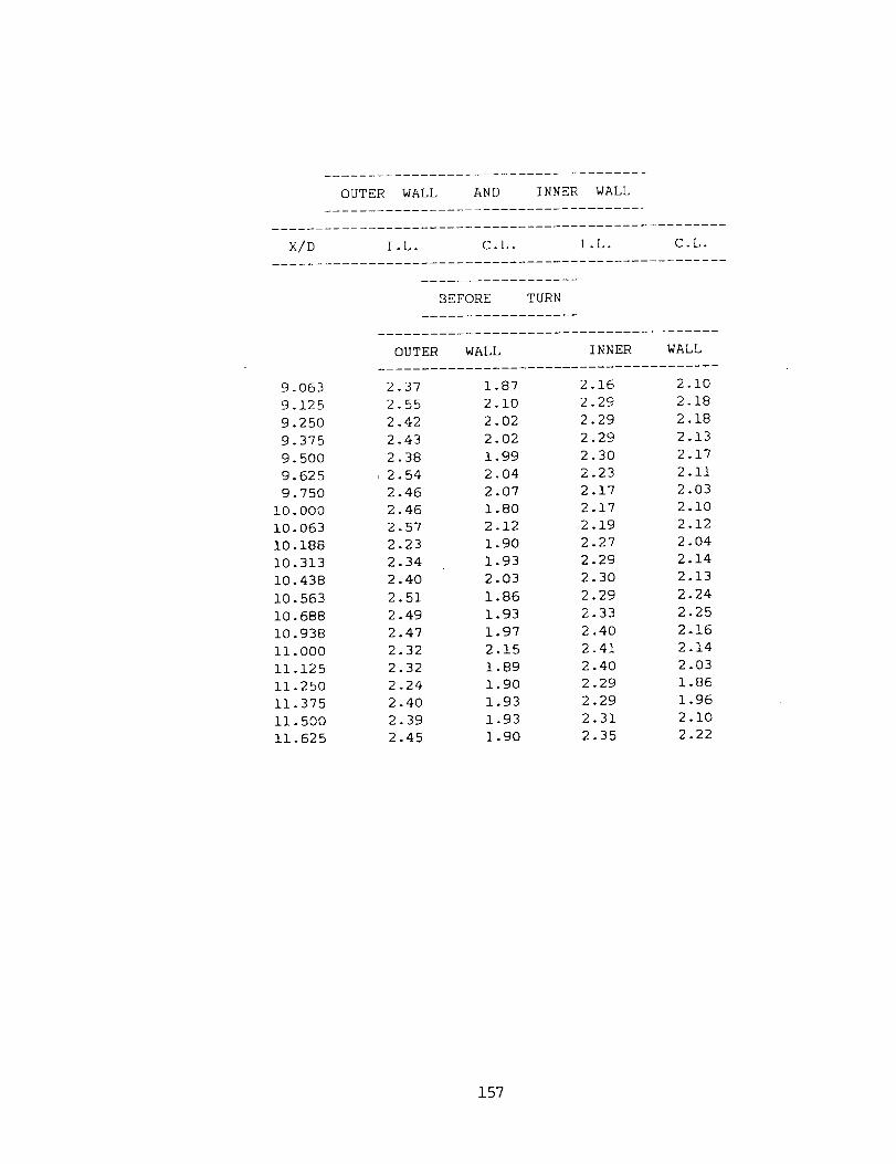
OUTERWALL AND INNER WALL
X/D I.L- C.L. I.L. C.L.
BEFORE TURN
OUTER WALL INNER WALL
9.063 2.37 1.87 2.16 2.109.125 2.55 2.10 2.29 2.189.250 2.42 2.02 2.29 2.189.375 2.43 2.02 2.29 2.139.500 2.38 1.99 2.30 2.179.625 , 2.54 2.04 2.23 2.119.750 2.46 2.07 2.17 2.03
i0.000 2.46 1.80 2.17 2.1010.063 2.57 2.12 2.19 2.1210.188 2.23 1.90 2.27 2.0410.313 2.34 1.93 2.29 2.1410.438 2.40 2.03 2.30 2.1310.563 2.51 1.86 2.29 2.2410.688 2.49 1.93 2.33 2.2510.938 2.47 1.97 2.40 2.16ii.000 2.32 2.15 2.41 2.1411.125 2.32 1.89 2.40 2.0311.250 2.24 1.90 2.29 1.8611.375 2.40 1.93 2.29 1.9611.500 2.39 1.93 2.31 2.1011.625 2.45 1.90 2.35 2.22
157

11.87512.37512.87513.12513.62514.125
14.37514.50014.62514.75014.87515.O0015.06315.31315.43815.56315.68815.81315.93816.00016.25016.37516.50016.62516.75016.87516.938
2.632.423.292.783.043.0]
2.932.892.902.732.902.892.912.922.882.942.912.932.973.022.862.692.682.662.822.862.88
IN TURN
2.052.423.262.903.O83.26
AFTER TURN
2.882.942.822.802.832.842.892.822.752.762.872.832.812.652.662.562.642.452.472.542.60
3.29
3.20
3.28
3.32
3.26
3.34
3.31
3.31
3.40
3.33
3.33
3.25
3.24
3.31
3.34
3.17
3.24
3.26
3.24
3.18
3.27
2.83
2.92
3.00
3.02
3.05
3.09
3.13
3.16
3.19
3.15
3.12
3.14
3.17
3.21
3.18
3.13
3.11
3.17
3.16
3.16
3.11
158

APPENDIX C
PRESSURE DROP DATA
159

LIST OF PRESSURE DROP TEST RUNS
CHANNEL
SMOOTH
ROUGH
ROUGH
ROUGH
ROUGH
ROUGH
Re
10,000
20,000
30,000
40,000
50,000
60,000
10,000
20,000
30,000
40,000
50,000
60,000
10,000
20,000
30,000
40,000
50,000
60,000
I0,000
20,000
30,000
40,000
50,000
60,000
10,000
20,000
30,000
40,000
50,000
60,000
10,000
20,000
30,000
40,000
50,000
60,000
P/e
10
10
10
10
10
10
I0
I0
10
10
I0
I0
10
10
10
10
10
10
20
20
20
20
20
20
10
10
10
10
10
10
e/D
0.063
0.063
0.063
0.063
0.063
0.063
0.063
0.063
0.063
0.063
0.063
0.063
0.063
0.063
0.063
0.063
0.063
0.063
0.063
0.063
0.063
0.063
0.063
0.063
0.094
0.094
0.094
0.094
0.094
0.094
Oz
90 °
90 °
90 °
90 °
90 °
90 °
60 °
60 °
60 °
60 °
60 °
60 °
45 °
45 °
45 °
45 °
45 °
45 °
90 °
90 °
90 °
90 °
90 °
90 °
90 °
90 °
90 °
90 °
90 °
90 °
Re : REYNOLDS NUMBER
P/e • PITCH-TO-RIB HEIGHT RATIO
e/D " RIB HEIGHT-TO-HYDRAULIC DIAMETER RATIO
o, : RIB ANGLE-OF-ATTACK
160

Smooth Channel
2(r'- r',,,,,,,)/ r,V
TAP X/D RE:Z0000 RE=20000 RE=30000 RE:40000 RE:B0000 RE:60000
1 0.3125 -1.9935 -1.9470 -1.9049 -1.8840 -1.8534 -1.797i
2 2.1875 -1.2931 -1.1763 -1.1142 -1.0900 -1.0776 -1.0633
3 4.6875 -1.3200 -1.2061 -i.1387 -1.0934 -1.0905 -1.0992
4 7.1875 -1.4009 -1.2710 -i.1980 -1.1640 -i.1638 -1.1382
5 9.6875 -1.4655 -1.3250 -1.2579 -1.2111 -1.1853 -1.1681
6 10.3125 -1.5086 -1.3440 -1.2639 -1.2313 -1.2069 -1.1981
7 10.9375 -1-5086 -1.3656 -1.2819 -1.2280 -1.2177 -1.2205
8 11.5625 -1.2392 -1.1493 -1.0603 -1.0429 -1.0345 -1.0034
9 13.0000 -2.1552 -1.9470 -1.9049 -1.8840 -1.8534 -1.8271
i0 14.4375 -2.9095 -2.7582 -2.6956 -2.6578 -2.5862 -2.5459
ii 15.0625 -4.2026 -3.8061 -3.6540 -3.5830 -3.5345 -3.3696
12 15.6875 -3.6638 -3.3532 -3.2587 -3.2297 -3.1034 -2.9802
13 16.3125 -3.2328 -3.0557 -2.9232 -2.8596 -2.8448 -2.6957
14 18.8125 -3.1789 -3.0287 -2.8813 -2.8260 -2.8017 -2.6657
15 21.3125 -3.3405 -3.1301 -2.9831 -2.9135 -2.8621 -2.7705
16 23.8125 -3.5022 -3.2856 -3.1149 -3.0279 -2.9957 -2.8604
161

Rough Channel P/e- 10, e/D ----0.063, (_- 90 °
2(P- P,,,t,,, )/pV 2
TAP X/D RE=I0000 RE:20000 RE:30000 RE:40000 RE=50000 RE:60000
1 0.3125 -2.1013 -2.0552 -2.0247 -2.0186 -1.9828 -1.8570
2 2.1875 -1.6918 -1.6766 -1.6473 -1.6149 -1.5948 -1.4976
3 4.68?5 - -1.7996 -1.7847 -1.7042 -1.6990 -1.6810 -1.5725
4 7.1875 -2.1121 -2.0957 -2.0367 -1.9849 -1.9612 -1.8870
5 9.6875 -2.4246 -2.4067 -2.3002 -2.2877 -2.2629 -2.1565
6 10.3125 -2.5108 -2.4986 -2.3961 -2.3550 -2.3362 -2.2614
7 10.9375 -2.5970 -2.5622 -2.4560 -2.4559 -2.4310 -2.3153
8 11.5625 -2.3707 -2.2985 -2.1265 -2.1868 -2.0690 -2.0367
9 13.0000 -3.3190 -3.2856 -3.1748 -3.1288 -3.0603 -2.9353
i0 14.4375 -4.0409 -4.0427 -3.8936 -3.8689 -3.7931 -3.6541
ii 15.O625 -4.8006 -4.7052 -4.5525 -4.4577 -4.3319 -4.1932
12 15.6875 -4.7953 -4.7323 -4.5525 -4.4745 -4.3103 -4.1633
13 16.3125 -4.8491 -4.7593 -4.5525 -4.5081 -4.3534 -4.2532
14 18.8125 -5.1724 -5.1109 -4.9119 -4.8782 -4.7414 -4.5826
15 21.3125 -5.5496 -5.4759 -5.2234 -5.1810 -5.0431 -4.9121
16 23.8125 -5.9267 -5.8140 -5.5709 -5.5174 -5.3879 -5.2715
162

TAP
Rough Channel" P/e -- 10, e/D -- 0.063, ol = 60"
2(P- P )//,vX/D RE:IO000 RE:20000 RE :30000 RE:40000 RE=50000 RE:60000
1 0.3125 -2.2629 -2.2309 -2.2224 -2.2137 -2.1983 -2.1865
2 2.1875 -1.9397 -1.8253 -1.7611 -1.6821 -1.6379 -1.6174
3 4.68?5 -2.1821 -2.1498 -2.0726 -1.9513 -1.9181 -1.8540
6 7.1875 -2.5862 -2.5690 -2.4560 -2.3886 -2.3491 -2.2913
5 9.6875 -3.0172 -2.9746 -2.9352 -2.8596 -2.8017 -2.7556
6 10.3125 -3.1358 -3.1098 -3.0550 -3.0009 -2.9095 -2.8754
7 10.9375 -3.2597 -3.2518 -3.1628 -3.0649 -3.0172 -2.9547
8 11.5625 -2.8556 -2.8123 -2.7555 -2.6914 -2.6293 -2.5908
9 13.O000 -3.3405 -3.3396 -3.2946 -3.2297 -3.0388 -2.9053
i0 14.4375 -4.3103 -4.2726 -4.1931 -4.1044 -3.8793 -3.7140
ii 15.0625 -5.2802 -5.2190 -5.1516 -5.0801 -4.9138 -4.7024
12 15.6875 -5.2802 -5.1379 -4.9718 -4.8446 -4.6983 -4.4928
13 16.3125 -5.0647 -4.8675 -4.7322 -4.6494 -4.4828 -4.3730
14 18.8125 -5.2263 -5.1109 -4.9718 -4.8446 -4.6983 -4.4928
15 21.3125 -5.6573 -5.5435 -5.3912 -5.2483 -5.0754 -4.8522
16 23.8!25 -6-0884 -5.9762 -5.8105 -5.6520 -5.4741 -5.2715
163

TAP
Rough Channel P/e -- 10, e/D -- 0.063, (t = 45 °
2(P- P,,,,,,)//,V
X/I) RE:I0000 RE=20000 RE:30000 RE:40000 RE:50000 RE:60000
] 0.3125 -2.2091 -2.2174 -2.1565 -2.153] -2.0690 -2.0517
2 "2.1875 -1.7241 -1.6495 -1.5874 -1.5812 -1.5086 -1.4676
3 4.6875 -1.9935 -1.9511 -1.8719 -1.8739 -1.7672 -1.6923
4 7.1875 -2.3168 -2.2715 -2.1565 -2.1195 -2.0043 -1.9169
5 9.6875 -2.6401 -2.5960 -2.4560 -2.4223 -2.2845 -2.2015
6 10.3125 -2.6940 -2.6501 -2.5159 -2.4896 -2.3621 -2.2763
7 10.9375 -2.7478 --2.7244 -2.6177 -2.5703 -2.4375 -2.3362
8 11.5625 -2.3707 -2.3526 -2.2763 -2.2204 -2.0474 -2.0068
9 13.0000 -3.1250 -3.0287 -2.9951 -2.8596 -2.6724 -2.5759
i0 14.4375 -3.9871 -3.9481 -3.7738 -3.5998 -3.2974 -3.1899
ii 15.0625 -5.6573 -5.5638 -5.3612 -5.1474 -4.8168 -4.7174
12 15.6875 -5.1724 -5.0568 -4.8520 -4.6764 -4.3534 -4.2831
13 16.3125 -4.7414 -4.6241 -4.4926 -4.3736 -4.0948 -4.0135
14 18.8125 -4.8491 -4.7323 -4.6124 -4.5(]81 -4.2241 -4.1333
15 21.3125 -5.1185 -5.0027 -4.8520 -4.7436 -4.4181 -4.3430
16 23.81L>5 -5.3879 -5.2731 -5.1156 -5.0464 -4.6767 -4.5976
164

TAP
[Rough Channel P/e --20, e/D --0.063, o:- 90"
Z/D RE=!O000 RE=20000 RE=30000 RE=40000 t2E=50000 RE--60000
1 0.3125 -2.1552 -2.0552 -2.0247 -2.0186 -2.0259 -1.9768
2 2.1875 -1.6164 -1.5955 -1.5215 -1.4803 -].4655 -1.3"178
3 4.6875 -1.7241 -1.7442 -1.6114 -1.5812 -1.5970 -1.4976
4 7.1875 -1.9935 -2.0011 -1.8330 -1.8167 -1.8534 -1.7372
5 9.6875 -2.2629 -2.2309 -2.0966 -2.0724 -2.0690 -1.9469
6 i0.3125 -2.3168 -2.2985 -2.1565 -2.1195 -2.1336 -1.9768
7 10.9375 -2.3707 -2.3526 -2.2164 -2.2204 -2.2198 -2.0442
8 11.5625 -2.1013 -2.0822 -1.9528 -1.9176 -1.8534 -1.7372
9 13.0000 -3.1250 -3.1098 -2.9352 -2.8933 -2.8448 -2.7855
i0 14.4375 -3.9332 -3.8940 -3.8337 -3.7344 -3.5991 -3.4445
ii 15.0625 -4.3103 -4.2658 -4.1332 -4.0371 -3.9009 -3.7290
12 15.6875 -4.5259 -4.4889 -4.3129 -4.2390 -4.1379 -3.9536
13 16.3125 -4.3642 -4.2726 -4.1452 -4.0371 -3.9655 -3.7589
14 18.8125 -4.6121 -4.5700 -4.3728 -4.2726 -4.1595 -3.9836
15 21.3125 -4.9030 -4.8675 -4.6124 -4.5418 -4.4397 -4.283]
16 213.81"25 -5.2263 -5.1109 -4.8520 -4.8109 -4.6983 -4.552"7
165
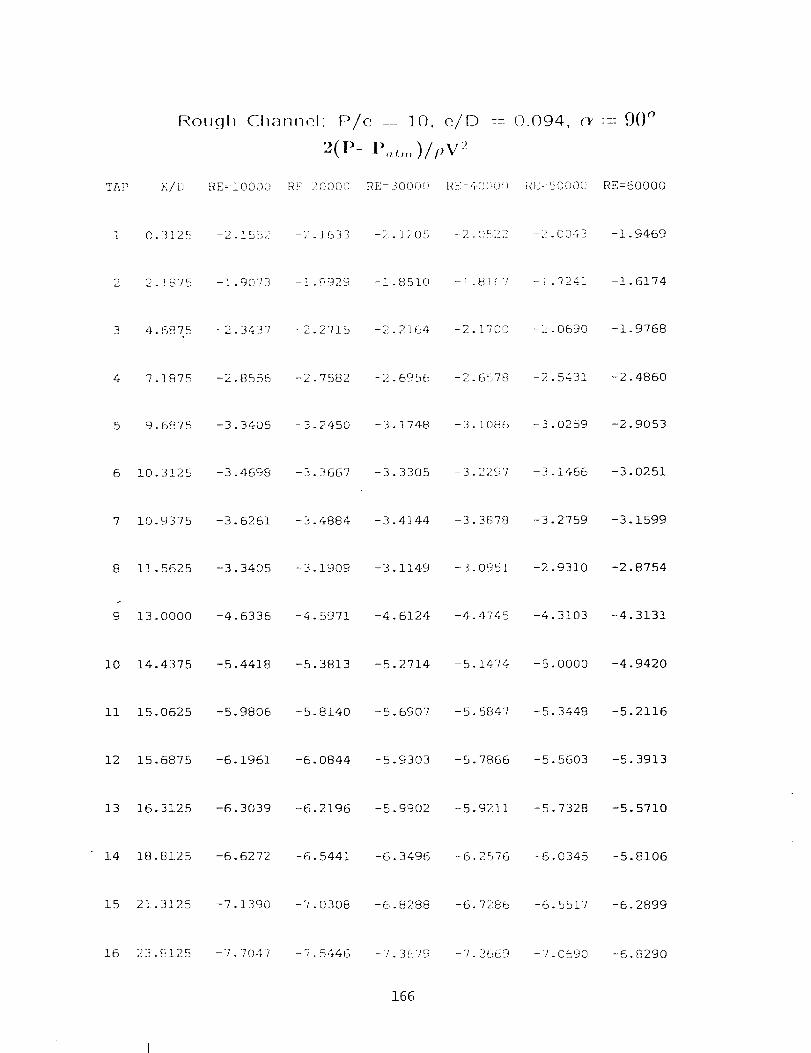
Rougll Cllaflnel P/e .... 10, e/D ---0.094, ,'_'- 90 °
2(P- P,,,,,,)/t,v ?
TAP X/IJ RE=iO000 RE: 20000 RE:300{):) RE=40000 RI:=kO000 RE:60000
1 0.3125 -2 ]552 -2.]633 -2 1205 -2.0522 -2.0043 -1.9469
2 2.1875 -I 907-3 -!.[{g29 -i 85].0 -1.81(,7 -1.7241 -1.6174
3 4.6875 -2 3437 -2.2"715 -2 2164 -2.1700 -2.0690 -1.9768
4 7 1875 -o 8556 -2 7582 _:) at- -2 -2.48606_:_6 .6_: 78 -2 54 _
5 9.6875 -3 3405 -3.2450 -3 1748 -3.1086 -3.0259 -2.9053
6 10.3125 -3 4698 -3.3667 -3 3305 -3.22:97 -3.1466 -3.0251
7 10.9375 -3.6261 -3.4884 -3 4144 -3.3S78 -3.2759 -3.1599
8 11.5625 -3.3405 --3.1909 -3 1149 -3.0951 -2.9310 -2.8754
9 13.0000 -4.6336 -4.5971 -4 6124 -4.4745 -4.3103 -4.3131
i0 14.4375 -5.4418 -5.3813 -5.2714 -5.1474 -5.0000 -4.9420
ii 15.0625 -5.9806 -5.8140 -5.6907 -5.5847 -5.3448 -5 2116
12 15.6875 -6.1961 -6.0844 -5.9303 -5.7866 -5.5603 -5 3913
13 16.3125 -6.3039 -6.2196 -5.9902 -5.9211 -5.7328 -5 5710
14 18.8125 -6.6272 -6.5441 -6.3496 -6.2576 -6.0345 -5 8106
15 21.3125 -7.1390 -7.0308 -6.8288 -6.7286 -6.5517 -6 2899
16 23.[{125 -7.7047 -7.5446 -7.3[</9 -7.2<]([9 -7.0690 -6 8290
166


I JJfftSA Report Documentation PageNal_ona_ Aeronau_l_ S and
Space Admlnl_traho(]
1. Repod No. NASA CR-1 79635 2 Government Accession No. 3. Recipienrs Catalog No.
AVSCOM TR-87-C-14
4. Title and Subtitle
Local Heat/Mass Transfer and Pressure Drop
Two-Pass Rib-Roughened Channel for Turbine
Airfoil Cooling
7. Author(s)
J.C. Han and P.R. Chandra
Ina
9. Performing Organization Name and _dress
Texas A&M UniversityTurbomachlnery LaboratoriesCollege Station, Texas 77843-3123
12. Sponsoring Agency Name and Address
U.S. Army Aviation Research and Technology Activity -AVSCOM, Propulsion Directorate, Lewis Research Center,Cleveland, Ohio 44135 and NASA Lewis Research Center,Cleveland, 0hlo 44135
51 RepoM Date
September 1987
6. Performing Organization Code
8. Pedorming Organization Re_d No.
None
t0. Work Unit No.
1L162209AH?6505-31-4K
11. Contract or Grant No.
NAS3-24227
13. Type of Report and Period Covered
Contractor ReportFinal
14. Sponsoring Agency Code
15, Supplementa_ Notes
Project Manager, Robert 3. Boyle, InternalNASA Lewis Research Center.
Fluid Mechanics Division,
16. Abstract
The heat transfer characteristics of turbulent air flow in a multipass channel were studied viathe naphthalene sublimation technique. The naphthalene-coated test section, which consisted of twostraight, square channels joined by a sharp 180° turn, resembled the internal cooling passages ofgas turbine airfoils. The top and bottom surfaces of the test channel were roughened by rib turbu-lators. The rib height-to-hydraulic diameter ratio (e/D) were 0.063 and 0.094, and the rib pitch-to-height ratio (P/e) were 10 and 20. The local heat/mass transfer coefficients on the roughenedtop wall and on the smooth divider and side walls of the test channel Were determined for threeReynolds numbers of 15,000, 30,000, and 60,000, and for three angles-of-attack (_) of 90°, 60°, and45°. The results showed that the local Sherwood nuffd)ers on the ribbed walls were 1.5 to 6.5 timesthose for a fully developedflow in a smoothsquareduct. The averageribbed-wallSherwoodnumbers
Were 2.5 to 3.5 times higherthanthe fullydevelopedvalues,dependingon the rib angle-of-attack
and the ReynoldsnLb_ber,the resultsalso indicatedthat,beforethe turn, the heat/masstransfer
coefficientsin the cases of e = 60° and 45° were higherthanthose in the caseof = = 90°. How-
ever,after the turn, the heat/masstransfercoefficientsin the oblique-ribcaseswere lowerthan
those in the traverse-ribcase. Correlationsfor the averageSherwoodnunl)erratiosfor individual
channelsurfacesand for the overallSherwoodnumberratiosare reported. Correlationsfor the
fully developedfrictionfactorsand for the losscoefficientsare also provided.
17. Key Words (Suggested by Author(s))
Heat transfer
AugmentationDucts
Turbine cooling
19, Security Classif. (of this repot)
Unclassified
18. Distribution Statement
Unclassified - Unlimited
Subject Category 34
20. Security Classif. (of this page)
Unclassified21, No of pages
]70
NASA FORM 1628 OCT 86 *For sale by the National Technical Information Service, Springfield, Virginia 22161
22. Price*
A