local water management strategy for lots 100 & … › files › assets › public › ...water...
TRANSCRIPT

Contact: Michael McCafferty File: 16180-Local Water Management Strategy Rev 0 Printed: 14/08/2019 9:24 AM Page 1 of 34
LOCAL WATER MANAGEMENT STRATEGY
FOR LOTS 100 & 101 HAZELMERE CIRCUS
AND LOT 95 LAKES ROAD, HAZELMERE 6055
PROJECT NUMBER #16180
REVISION 0, DATE 14TH
AUGUST 2019

Contact: Michael McCafferty File: 16180-Local Water Management Strategy Rev 0 Printed: 14/08/2019 9:24 AM Page 2 of 34
TABLE OF CONTENTS
EXECUTIVE SUMMARY ............................................................................................................ 4
1 Introduction ..................................................................................................................... 7
Background .......................................................................................................................... 7
Town planning context .......................................................................................................... 7
Policy framework .................................................................................................................. 8
Previous studies .................................................................................................................... 8 1.4.1 District Stormwater Management Strategy ........................................................................................... 8
LWMS objectives .................................................................................................................. 9
2 Proposed Development .................................................................................................... 9
3 Pre-development Environment ......................................................................................... 9
Sources of information .......................................................................................................... 9
Climate ............................................................................................................................... 10
Geotechnical conditions ...................................................................................................... 10 3.3.1 Topography .......................................................................................................................................... 10 3.3.2 Soils and geology.................................................................................................................................. 11 3.3.3 Acid Sulfate Soils .................................................................................................................................. 12
Figure 4 – ASS Mapping of the site ........................................................................................ 13
Surface water ..................................................................................................................... 14 3.4.1 Existing drainage network .................................................................................................................... 14
Surface water monitoring .................................................................................................... 15 3.5.2 Surface water quality results ............................................................................................................... 15 3.5.3 Pre-development surface runoff modelling ......................................................................................... 15
Groundwater ...................................................................................................................... 16 3.6.1 Groundwater levels .............................................................................................................................. 16 3.6.2 Groundwater quality ............................................................................................................................ 17
Current and historical land uses ........................................................................................... 18
Summary of existing environment ....................................................................................... 18
4 Design Criteria and Objectives ........................................................................................ 19
Water conservation ............................................................................................................ 19
Groundwater management ................................................................................................. 19 4.2.2 Stormwater management .................................................................................................................... 19
5 Water Source Allocation, Infrastructure, Fit-for-Purpose and Water Use ......................... 20
Fit-for-purpose water use .................................................................................................... 20 5.1.1 Scheme water ...................................................................................................................................... 20 5.1.2 Groundwater ........................................................................................................................................ 20
Water conservation measures ............................................................................................. 20 5.2.1 Dry Industry scale conservation measures .......................................................................................... 20 5.2.2 Water efficient fittings ......................................................................................................................... 20
Wastewater management ................................................................................................... 21
6 Groundwater Management Strategy .............................................................................. 21

Contact: Michael McCafferty File: 16180-Local Water Management Strategy Rev 0 Printed: 14/08/2019 9:24 AM Page 3 of 34
Groundwater level management ......................................................................................... 21 6.1.2 Groundwater levels .............................................................................................................................. 21
Groundwater quality management ...................................................................................... 21
7 Stormwater Management Strategy ................................................................................ 22
WSUD strategies ................................................................................................................. 22 7.1.1 Grease and sediment traps .................................................................................................................. 22 7.1.2 Trash racks ........................................................................................................................................... 22
Drainage design assessment ................................................................................................ 23 7.2.1 Hardstand drainage ............................................................................................................................. 23
Non-structural water quality measures ................................................................................ 23
8 Urban Water Management Plans ................................................................................... 24
Stormwater storage and infiltration within lot ..................................................................... 24
Imported fill specifications .................................................................................................. 24
Implementation of water conservation strategies ................................................................ 24
Non-structural water quality improvement measures .......................................................... 24
Nutrients, management and maintenance requirements ..................................................... 25
Construction period management strategy .......................................................................... 25
Monitoring and evaluation program .................................................................................... 25
9 Monitoring and Maintenance ......................................................................................... 26
Management and maintenance ........................................................................................... 26
Water quality monitoring .................................................................................................... 26 9.2.1 Pre-development monitoring .............................................................................................................. 26 9.2.2 Post-development monitoring ............................................................................................................. 26 9.2.3 Post-development trigger values ......................................................................................................... 26
Contingency action plan ...................................................................................................... 27 9.3.1 Trigger criteria ...................................................................................................................................... 27 9.3.2 Contingency actions ............................................................................................................................. 27
Reporting ........................................................................................................................... 28
10 Implementation .......................................................................................................... 28
Roles and responsibility ................................................................................................... 28
Conclusions and recommendations .................................................................................. 29
11 References .................................................................................................................. 30
General references .......................................................................................................... 30
Online references ............................................................................................................ 32
Appendix 1 – Drainage Calculations ...................................................................................... 33

Contact: Michael McCafferty File: 16180-Local Water Management Strategy Rev 0 Printed: 14/08/2019 9:24 AM Page 4 of 34
EXECUTIVE SUMMARY
Roselink Investments Pty Ltd propose to develop Lots 100 & 101 Hazelmere Circus and Lot 95 Lakes Road, Hazelmere
6055 within the Hazelmere Enterprise Area Structure Plan (HEASP) for dry industrial land use. This landholding (herein
referred to as “the site”) is located within the City of Swan (CoS).
The proposed development area covers approximately 6.9 ha, and is bound to the South by Lakes Road, the
South West by Hazelmere Circus, and other lots to the East, North West and North. The development sites are
predominately cleared and contain hardstand areas, residential dwellings and agricultural farming.
The proposed development is for dry industrial use that will convert the entire site to predominantly impervious
surfaces comprising of a combination of hardstand and roofed buildings.
The subject site is zoned Industrial under the Metropolitan Region Scheme and “Special Use 25” under the City
of Swan Local Planning Scheme No. 17 (LPS17). The site is located within Precinct 3B in the Hazelmere
Enterprise Area and is identified as an ‘Existing Industrial Zone’ restricted to ‘Dry Industrial Activities’.
The Local Water Management Strategy (LWMS) is prepared to support the proposed Local Structure Plan (LSP)
for Lots 100 & 101 Hazelmere Circus and Lot 95 Lakes Road, Hazelmere. The LSP provides the framework for
the site to be developed as a light industry land use as per City of Swan Local Planning Scheme 17 zoning table.
The proposed land use suits the conditions of the Special Use area for ‘dry industry’ and acts as a transitional
land use between the General Industrial and the ‘Special Use 16’ land to the west.
This Local Water Management Strategy (LWMS) has been developed in accordance with Better Urban Water
Management, State Planning Policy 2.9 Water Resources, Planning Bulletin 92 Urban Water Management and
Interim: Developing a Local Water Management Strategy. Water will be managed using an integrated water cycle
management approach, which has been developed using the philosophies and design approaches described in
the Stormwater Management Manual for Western Australia.
The first step in applying integrated water cycle management in urban catchments is to establish agreed
environmental values for receiving waters and their ecosystems. Characteristics of both the existing and past
environment within the site have been investigated. In summary, the environmental investigations conducted to
date indicate that:
• The site receives an average of 766 mm annual rainfall with the majority of rainfall received in June and
July.
• Topography of the site is fairly flat and ranges from 12.5m Australian height datum (AHD) in the south
to 14m AHD in the north west of Lot 95 Lakes Road.
• The majority of the site is mapped as having a moderate to low risk of encountering acid sulfate soils
(ASS) within 3m of the surface. The northern boundary of Lot 95 Lakes Road has a high to moderate
risk of ASS occurring within 3m of the natural soil surface.
• The land in the surrounding area of the site is categorised as Industrial and Rural Residential.
• Hydrological modelling of the site is based on Australian Rainfall and Runoff (AR&R) and in further detail,
based on the previous modelling of the greater HEASP documented in the District Stormwater
Management Strategy (DSMS).
• Helena River is located approximately 1.2km north of the site.
• The site has historically been used for rural lifestyle and equine (trotting) purposes.
The overall objectives for integrated water cycle management for industrial developments is to minimise pollution
and maintain an appropriate water balance. The LWMS design objectives seek to deliver best practice outcomes
using a Water Sensitive Urban Design (WSUD) approach, including detailed management approaches for:
Contact: Michael McCafferty File: 16180-Local Water Management Strategy Rev 0 Printed: 14/08/2019 9:24 AM Page 5 of 34
• Potable water consumption
• Flood mitigation
• Stormwater quantity and quality management
• Groundwater management.
The criteria proposed within this LWMS are based on the approved DSMS, the characteristics of the existing
environment and a contemporary best-practice approach to integrated water cycle management.
The overall approach to water conservation is to minimise water requirements, for the establishment and
maintenance of the drainage basin and landscaped areas within the development. This will be achieved through the
use of waterwise landscaping practices, including use of native vegetation where possible.
Stormwater management focusses on two key aspects:
1. Stormwater peak flow rates will not exceed predevelopment flow rates
2. Stormwater runoff quality.
The principle behind the stormwater management strategy for the site is to maintain the existing hydrology by
storing the 1 Year 1 Hour Storm Event water volume. There are no existing upstream catchments flowing
through this site. Lot detention is proposed through a drainage basin located on each lot near Hazelmere Circus
and Lakes Road, which will be landscaped to improve the aesthetics of the site. The 1 Year 1 Hour Water
volume will be stored as per the City of Swan requirements.
The basin will be designed so that storm events beyond the 1 Year 1 Hour event will breakout towards
Hazelmere Circus and Lakes Road.
The main objective of the management of groundwater quality is to maintain or improve runoff that could either be
infiltrated to groundwater or that could be discharged from the site. This will be achieved by reducing the total
nutrient load that originates from the development through treatment of surface water runoff from frequent events
prior to infiltration to groundwater and through implementation of nutrient minimising landscape management
practices.
The proposed design criteria and the manner in which they are proposed to be achieved are presented in
Table 1. This table provides a readily auditable summary of the required outcomes which can be used in the
future detailed design stage to demonstrate that the agreed objectives for water management at the site have
actually been achieved.
This LWMS demonstrates that, by following the recommendations detailed in the report, the site is capable of
being developed.
Contact: Michael McCafferty File: 16180-Local Water Management Strategy Rev 0 Printed: 14/08/2019 9:24 AM Page 5 of 34
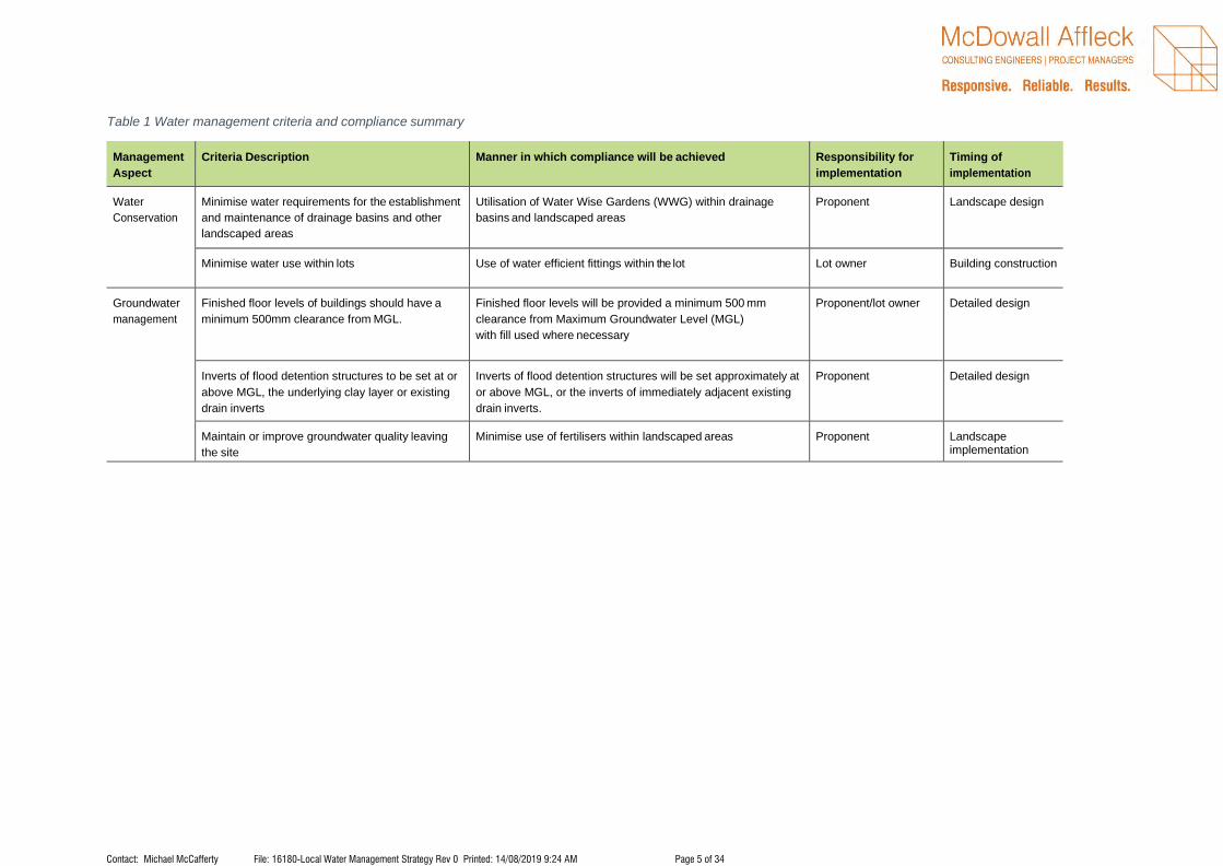
Table 1 Water management criteria and compliance summary
Management
Aspect
Criteria Description Manner in which compliance will be achieved Responsibility for
implementation
Timing of
implementation
Water
Conservation
Minimise water requirements for the establishment
and maintenance of drainage basins and other
landscaped areas
Utilisation of Water Wise Gardens (WWG) within drainage
basins and landscaped areas
Proponent Landscape design
Minimise water use within lots Use of water efficient fittings within the lot Lot owner Building construction
Groundwater
management
Finished floor levels of buildings should have a
minimum 500mm clearance from MGL.
Finished floor levels will be provided a minimum 500 mm
clearance from Maximum Groundwater Level (MGL)
with fill used where necessary
Proponent/lot owner Detailed design
Inverts of flood detention structures to be set at or
above MGL, the underlying clay layer or existing
drain inverts
Inverts of flood detention structures will be set approximately at
or above MGL, or the inverts of immediately adjacent existing
drain inverts.
Proponent Detailed design
Maintain or improve groundwater quality leaving
the site
Minimise use of fertilisers within landscaped areas Proponent Landscape implementation

Contact: Michael McCafferty File: 16180-Local Water Management Strategy Rev 0 Printed: 14/08/2019 9:24 AM Page 6 of 34
Management
Aspect
Criteria Description Manner in which compliance will be achieved Responsibility for
implementation
Timing of
implementation
Surface water
management
Runoff from the lot will be treated at source Appropriate treatment measures will be required on lot Proponent Detailed design
Detain flows up to the 1 Year 1-hour ARI storm
event within the boundary of the lot.
City of Swan requires the lots to detain flows up to the 1 Year 1 Hour ARI event
Lot developer Lot development approvals
Management
Aspect
Criteria Description Manner in which compliance will be achieved Responsibility for
implementation
Timing of
implementation
Finished floor levels should have a 300 mm
clearance from the 100-year ARI water level within
conveyance swales and the flood detention
structure
Finished floor levels will have a minimum clearance of 300 mm
from the 100-year ARI top water level within swales with fill
used where necessary
Proponent Detailed design
Apply appropriate non-structural measures to
reduce pollutant loads
Minimise fertiliser use to establish and maintain vegetation
within drainage reserves and road verges
Proponent Landscape
implementation
Use drought tolerant turf species that require minimal water
and nutrients
Proponent Landscape
implementation
Education of lot owner regarding fertiliser use and nutrient
absorbing vegetation species within lots
Proponent Point of sale

Contact: Michael McCafferty File: 16180-Local Water Management Strategy Rev 0 Printed: 14/08/2019 9:24 AM Page 7 of 34
1 INTRODUCTION
BACKGROUND
The land owners propose to develop Lots 100 & 101 Hazelmere Circus and Lot 95 Lakes Road, Hazelmere
6055 within the Hazelmere Enterprise Area Structure Plan (HEASP) for dry Industrial Land use, as shown in
Figure 1. This landholding (herein referred to as “the site”) is located within the City of Swan (CoS).
Figure 1: Site Location
The proposed development area covers approximately 6.9 ha, the proposed development area is bound to
the West by Hazelmere Circus, to the south by Lakes Road, and other lots to the East and North. The
development site is predominately cleared and contains a hardstand area, horse paddock and stables and
residential dwellings.
The proposed development is for dry industrial use that will convert the subject lots to hardstand and roofed
buildings.
TOWN PLANNING CONTEXT
The subject site is zoned Industrial under the Metropolitan Region Scheme and “Special Use 25” under the
City of Swan Local Planning Scheme No 17 (LPS17). The site is located within Precinct 3B in the Hazelmere
Enterprise Area and is identified as an ‘Existing Industrial Zone’ restricted to ‘Dry Industrial Activities’.

Contact: Michael McCafferty File: 16180-Local Water Management Strategy Rev 0 Printed: 14/08/2019 9:24 AM Page 8 of 34
The Local Water Management Strategy (LWMS) is prepared to support the proposed Local Structure Plan
(LSP) for Lots 100 & 101 Hazelmere Circus and Lot 95 Lakes Road, Hazelmere. The LSP provides the
framework for the site to be developed as light industry land uses. The proposed land use suits the
conditions of the Special Use area for ‘dry industry’ and acts as a transitional land use between the General
Industrial and the ‘Special Use 16’ land to the west.
POLICY FRAMEWORK
There are several State and Local Government policies and planning schemes of relevance to the site. These
policies include:
• State Water Strategy (Government of WA 2003)
• State Water Plan (Government of WA 2007)
• State Planning Policy 2.9 Water Resources (WAPC 2006a)
• Guidance Statement No. 33: Environmental Guidance for Planning and Development (EPA 2008)
• Planning Bulletin No. 64: Acid Sulfate Soils (WAPC 2009)
• State Planning Policy 2.10: Swan and Canning River System (WAPC 2006b)
• Local Planning Scheme No. 17 (CoS 2008)
• Hazelmere Enterprise Area Structure Plan (CoS 2011)
In addition to the above policies and schemes, there are several published guidelines and standards available
that provide direction regarding the water discharge characteristics that urban developments should aim to
achieve.
These provide key inputs that relate either directly or indirectly to the site and include:
• Better Urban Water Management (WAPC 2008)
• Australian Runoff Quality (Engineers Australia 2006)
• Australian Rainfall and Runoff (Engineers Australia 1987)
• Decision Process for Stormwater Management in Western Australia (DWER 2017)
• Developing a Local Water Management Strategy (DoW 2008a)
• Stormwater Management Manual for Western Australia (DoW 2007)
• National Water Quality Management Strategy (NWQMS) (ANZECC 2000)
• Swan and Canning Water Quality Improvement Plan (SCWQIP) (SRT 2009).
The guidance documents listed indicate a need for accurate water quality baseline data prior to urban
development. This will ensure that any future development is able to fulfil the stormwater management
requirements of DWER and engineering standards specified by Local Government. It will also ensure that a
realistic water management criteria is adopted that is practical and achievable.
PREVIOUS STUDIES
1.4.1 DISTRICT STORMWATER MANAGEMENT STRATEGY
The Hazelmere Enterprise Area District Stormwater Management Strategy (DWMS) (AECOM 2010) was
prepared to support the HEASP District Structure Plan for City of Swan.
Key catchment objectives applicable to the proposed local structure plan are summarised below:
• Flood protection

Contact: Michael McCafferty File: 16180-Local Water Management Strategy Rev 0 Printed: 14/08/2019 9:24 AM Page 9 of 34
o All habitable floor levels on lots to be designed to maintain a minimum separation clearance
of 500mm to the internal 100-year ARI flood levels.
o Protection of buildings and infrastructure with conveyance and storage of flood waters via
the open and piped drainage network and road reserves.
o Discharge of the 10-year ARI flows from the site does not exceed predevelopment flows.
o Discharge of controlled 100-year ARI flood flows to Hazelmere Circus and Lakes Road
does not exceed predevelopment flows.
o Designated 100-year ARI flow paths to protect infrastructure from flood risks.
• Stormwater management
o Utilise drainage pipes and swales to convey flows through the development.
o Lot storage and treatment of the 1 year 1-hour ARI event on site.
• Water conservation and servicing
o Development to be connected to a potable reticulated water supply.
o Encouragement of water efficient fixtures and fittings for all buildings constructed.
LWMS OBJECTIVES
This LWMS has been developed in consideration of the objectives and principles detailed in the overarching
DWMS, detailed in Section 1.4 and Better Urban Water Management (WAPC 2008). It is intended to support
the local structure plan of the site, and is further based on the following major objectives:
• Provide a broad level stormwater management framework to support future industrial development.
• Develop a water conservation strategy for the site that will ensure the efficient use of all water
resources.
• Gain support from DWER and local government for the proposed method to manage stormwater
within the site.
Detailed objectives for water management within the site are further discussed in Section 4.
2 PROPOSED DEVELOPMENT
Statewest Planning have prepared an Local Structure Plan (LSP) for the site which covers an area of 6.9
hectares (ha), and outlines the future industrial land use across the site, including:
• Areas to be developed for dry industrial land uses.
• The provision and location of areas to accommodate stormwater drainage requirements via the
Local Water Management Strategy (LWMS).
The proposed light industry land use is in line with the proposed dry industrial zoning.
The key elements of the water management approach are:
• Lots detain runoff for 1 Year 1 Hour ARI in accordance with the City of Swan drainage guidelines.
• Outflows from the site to not exceed predevelopment flows.
3 PRE-DEVELOPMENT ENVIRONMENT
SOURCES OF INFORMATION
The following sources of information were used to provide a broad regional environmental context for the site:
• National Water Quality Management Strategy (ANZECC 2000)
• Regional 1:50 000 Geology Map Sheet (Jordan 1986)

Contact: Michael McCafferty File: 16180-Local Water Management Strategy Rev 0 Printed: 14/08/2019 9:24 AM Page 10 of 34
• WA Atlas (Landgate 2015)
• Water Register (DWER 2015b)
• Perth Groundwater Atlas (DWER 2015a)
• Weather and Climate Statistics Data (BoM 2015).
The City of Swan have previously commissioned a range of studies and investigations across the HEASP to
understand the environmental attributes and values of the area and to demonstrate the feasibility of industrial
development. The various reports associated with these investigations have been reviewed as part of the
preparation of this document and include:
• Hazelmere Enterprise Area District Stormwater Management Strategy (AECOM 2010)
• Hazelmere Enterprise Area Structure Plan (City of Swan 2011)
• Local Planning Scheme No. 17 (City of Swan 2008)
• Hazelmere Enterprise Area District Structure Plan, Environmental Assessment (Hassell 2010)
• Helena River Foreshore Definition (AECOM 2010a)
The above studies have been reviewed to determine any potential limitation of local surface water flow paths
and existing surface and groundwater levels. This is important, as they can have implications for the
stormwater management measures and the extent of earthworks that may be required to facilitate development.
CLIMATE
The climate of the site (which applies to the wider Perth metropolitan region) is described as Mediterranean,
with hot, dry summers and moderately wet, mild winters. The closest weather station to the site which records
rainfall and temperature data is located approximately 3.3 km south of the site (Bureau of Meteorology (BoM)
station number 9021). Based on weather data collected from 1944 to 2019, the area experiences an average
of 766mm of annual rainfall (Bureau of Meteorology 2019).
GEOTECHNICAL CONDITIONS
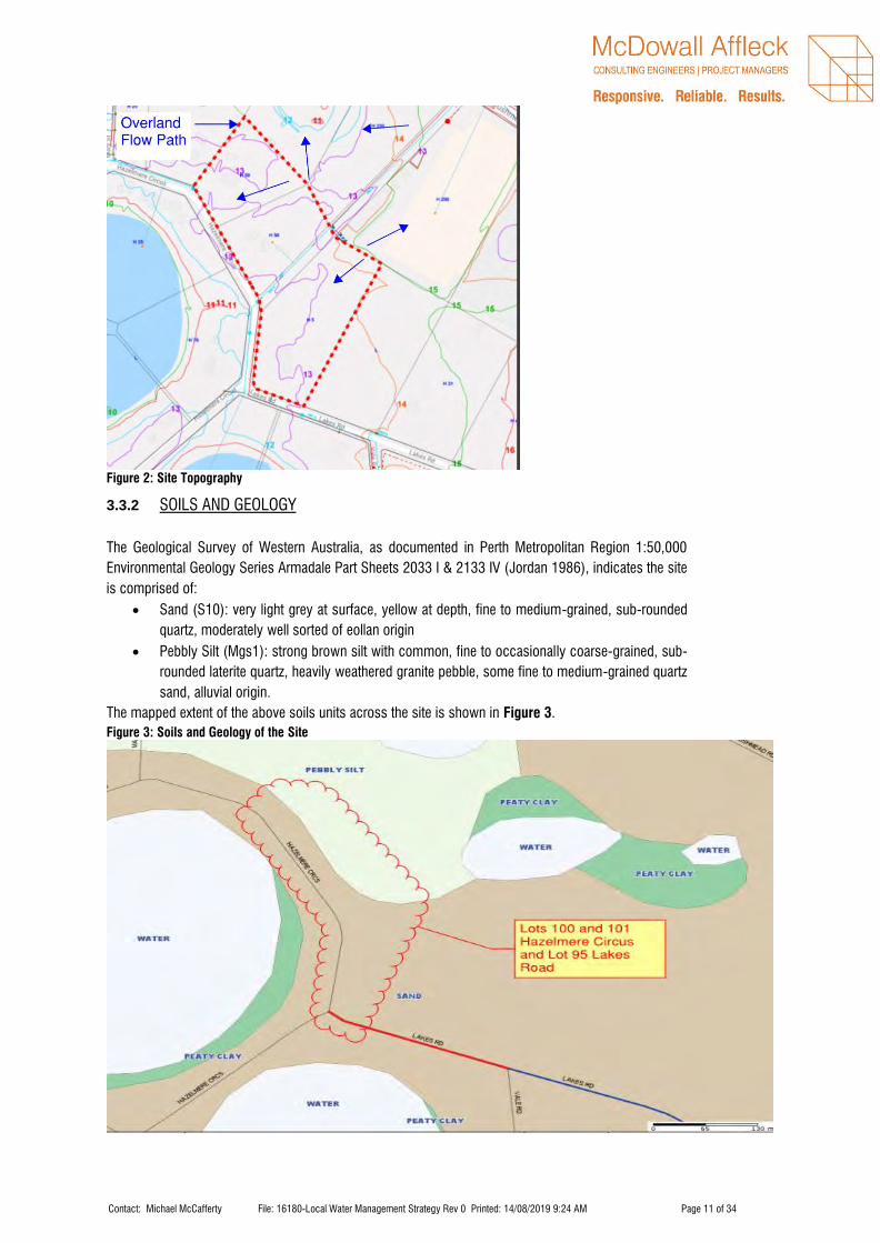
3.3.1 TOPOGRAPHY
The site is fairly flat and ranges from 12.5 m Australian height datum (AHD) in the south to 14 m AHD in the
north west of Lot 95 Lakes Road.
The site drains towards Lakes Road with no external catchments flowing through the site (refer below)
Topographical contours are shown in Figure 2, indicating the elevation characteristics of the site.
Contact: Michael McCafferty File: 16180-Local Water Management Strategy Rev 0 Printed: 14/08/2019 9:24 AM Page 11 of 34
Figure 2: Site Topography
3.3.2 SOILS AND GEOLOGY
The Geological Survey of Western Australia, as documented in Perth Metropolitan Region 1:50,000
Environmental Geology Series Armadale Part Sheets 2033 I & 2133 IV (Jordan 1986), indicates the site
is comprised of:
• Sand (S10): very light grey at surface, yellow at depth, fine to medium-grained, sub-rounded
quartz, moderately well sorted of eollan origin
• Pebbly Silt (Mgs1): strong brown silt with common, fine to occasionally coarse-grained, sub-
rounded laterite quartz, heavily weathered granite pebble, some fine to medium-grained quartz
sand, alluvial origin.
The mapped extent of the above soils units across the site is shown in Figure 3.
Figure 3: Soils and Geology of the Site

Contact: Michael McCafferty File: 16180-Local Water Management Strategy Rev 0 Printed: 14/08/2019 9:24 AM Page 12 of 34
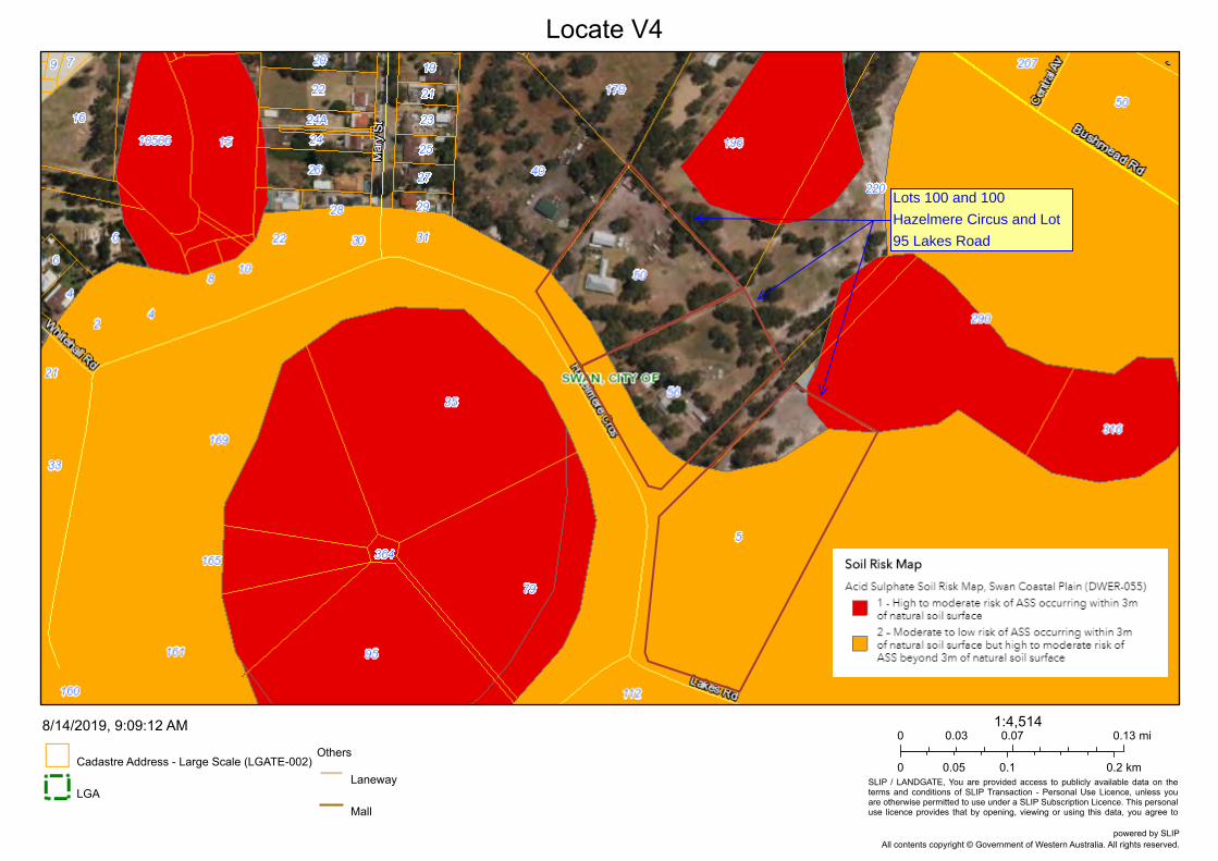
3.3.3 ACID SULFATE SOILS
Regional acid sulfate soils (ASS) risk mapping (DER 2006) indicates that the south western ends of Lots
100 and 101 Hazelmere Circus have a moderate to low risk of ASS occurring within 3m of the natural
soil surface but a high to moderate risk of ASS beyond 3m of the natural soil surface. The majority of Lot
95 Lakes Road has a moderate to low risk of ASS occurring within 3m of the natural soil surface but high
to moderate risk of ASS beyond 3 m of the natural soil surface. The area located at the northern boundary
of Lot 95 Lakes Road has a high to moderate risk of ASS occurring within 3m of the natural soil surface.
The ASS mapping is shown in Figure 4.

Contact: Michael McCafferty File: 16180-Local Water Management Strategy Rev 0 Printed: 14/08/2019 9:24 AM Page 13 of 34
FIGURE 4 – ASS MAPPING OF THE SITE
Locate V4
SLIP / LANDGATE, You are provided access to publicly available data on theterms and conditions of SLIP Transaction - Personal Use Licence, unless youare otherwise permitted to use under a SLIP Subscription Licence. This personaluse licence provides that by opening, viewing or using this data, you agree to
Cadastre Address - Large Scale (LGATE-002)
LGA
Others
Laneway
Mall
8/14/2019, 9:09:12 AM0 0.07 0.130.03 mi
0 0.1 0.20.05 km
1:4,514
All contents copyright © Government of Western Australia. All rights reserved.powered by SLIP
Lots 100 and 100
Hazelmere Circus and Lot
95 Lakes Road

Contact: Michael McCafferty File: 16180-Local Water Management Strategy Rev 0 Printed: 14/08/2019 9:24 AM Page 14 of 34
SURFACE WATER
3.4.1 EXISTING DRAINAGE NETWORK
The site has no existing constructed drainage network on site. All roof runoff is collected via a guttering system
and stored in rainwater tanks on site. Groundwater runoff follows the existing slope of the land towards the
south and into the northern Hazelmere Lake. There is no council drainage system located on Hazelmere Circus
or Lakes Road.
It is proposed that each lot will handle its own drainage,
Photo 1: Lot 100 Hazelmere Circus General Site Photo
Photo 2: Lot 101 Hazelmere Circus General Site Photo

Contact: Michael McCafferty File: 16180-Local Water Management Strategy Rev 0 Printed: 14/08/2019 9:24 AM Page 15 of 34
Picture 3: Lot 95 Lakes Road General Site Photo
SURFACE WATER MONITORING
3.5.2 SURFACE WATER QUALITY RESULTS
Groundwater monitoring was taken during the DWMS and presented below.
Table 2 Pre-development surface water quality results
Analyte
Units
NWQMS
guideline
trigger*
SCWQIP
guideline
trigger*
SW2
SW3
Average
St.dev
Average
St.dev
Temperature
ºC
-
-
28.9
2.9
28.9
2.9
pH
6.5-8.0
-
8.05
n/a
7.95
0.46
Electrical Conductivity (EC)
µS/cm
90-900
-
2150 -
1713 -
Total nitrogen (TN)
mg/L
1.2
1 - 2
4.67 1.29 3.06 2.51
NO2-N
mg/L
-
- 0.02 0 0.02 0.006
Nitrate-NO3
mg/L
-
- 0.03 0.02 0.08 0.04
Total kjehldahl nitrogen (TKN)
mg/L
-
- 4.63 1.23 3 2.54
Total phosphorous (TP)
mg/L
0.065
0.1 - 0.2 2.30 0.45 0.67 0.97
*(ANZECC 2000); values taken from (ENV 2009)
Both TN and TP concentrations are both outside guideline trigger values provided in the SCWQIP (SRT 2009)
and NWQMS (ANZECC 2000).
3.5.3 PRE-DEVELOPMENT SURFACE RUNOFF MODELLING
McDowall Affleck has calculated the pre-development and post-development storage requirements in
accordance with Australian Rainfall and Runoff based on the proposed rezoning of the site and conversion to
a full hardstand site.
We have based the storage requirements on the lots being 100% combination of hardstand areas as a worst-
case scenario. However, we have noted that surrounding land uses have a combination of landscaped,
hardstand and roofed areas.
Storage requirements are based on the City of Swan Handbook of Stormwater Drainage Design requirements.
Final storage requirements can be determined at the Urban Water Management Plan Stage.
Figure 4 shows a conceptual location for the drainage basins, the exact location and size of the basins will be
confirmed at a later stage.

Contact: Michael McCafferty File: 16180-Local Water Management Strategy Rev 0 Printed: 14/08/2019 9:24 AM Page 16 of 34
Figure 4: Proposed Basin Locations (to be confirmed at a later stage)
Table 3 Peak Storage Requirements for 1 Year 1 Hour ARI and storage provided
Address Storage Required (m3) Storage Provided (m3)
Lot 100 Hazelmere Circus 286 292
Lot 101 Hazelmere Circus 288 292
Lot 95 Lakes Road 512 516
q
GROUNDWATER
3.6.1 GROUNDWATER LEVELS
Information on groundwater from the DWER online Water Register (DWER 2018) indicates that
groundwater beneath the site is a multi-layered system comprised of the following:
• Perth – Superficial Swan unconfined aquifer
• Perth – Leederville confined aquifer
• Perth – Yarragadee North confined aquifer.
Groundwater data from the Perth Groundwater Atlas show that maximum groundwater levels across the site
range between 6.0m AHD and 7.0m AHD (DWER 2018b) which is inconsistent with the groundwater
modelling completed by ENV as part of the DWMS.

Contact: Michael McCafferty File: 16180-Local Water Management Strategy Rev 0 Printed: 14/08/2019 9:24 AM Page 17 of 34
Groundwater monitoring was carried out by ENV for 6 months commencing in October 2008 (ENV 2010)
with 19 monitoring bores installed across the broader DWMS area. Three of these were located close to the
site. X6 was located approximately 550m to the west of the site, X7 was located approximately 660m to the
east of the site and X19 was located approximately 920m to the south east of the site. Data loggers were
installed in each of the bores with manual measurements taken quarterly for calibration purposes.
Maximum Groundwater Level (MGL) monitoring completed by ENV as part of the DWMS indicate that our
site has an MGL of approximately 11.0m AHD (2.5m deep). The monitoring results showed that the site is
subject to the seasonal perching of groundwater and is highly responsive to rainfall (ENV 2010). The
groundwater clearance at the basins located on the lots is approximately 2m on Lots 100 and 101 Hazelmere
Circus and approximately 2.5m at Lot 95 Lakes Road. These drainage basins have adequate clearance for
an infiltration drainage basin.
3.6.2 GROUNDWATER QUALITY
Water quality monitoring was carried out at two locations near the site on 2 occasions between November
2008 and February 2009. Monitoring included sampling of physio- chemical parameters in situ and laboratory
analysis of nutrients, metals and other analytes (ENV 2010). The measured groundwater quality is
summarised in Table 4 and details the parameters significant to, and managed within, this LWMS (i.e. physio-
chemical parameters and nutrient concentrations).
Table 4 Groundwater quality
Analyte
Units
NWQMS
guideline
trigger*
SCWQIP
guideline
trigger*
X6
X7
Ave
St dev
Ave
St dev
Temp
ºC - - 28.95 4.17 28.95 4.17
pH 6.5-8.0 -
7.38
- 6.66 -
EC
µS/cm 300-1500 - 2960 - 560 -
TN
mg/L 1.2 1 - 2 5.5 - 1.2 -
NO2-N
mg/L - - 0.025 - <0.01 0
Nitrate-NO3
mg/L - - 0.08 - 0.065 0.07
TKN
mg/L
- 5.4 - 1.15 0.21
TP
mg/L 0.065 0.1 - 0.2
2.35
-
0.115
0.35
*(ANZECC 2000); values taken from (ENV 2010)
As shown in Table 4, groundwater beneath the site has a medium pH and high salinity. TN and TP
concentrations are considered ‘High’ to ‘Moderate’ in relation to SCWQIP (SRT 2009) and NWQMS
(ANZECC 2000) guidelines trigger values. These concentrations are representative of the historical land use
of the site including residential and dry industrial (discussed in Section 3.7).

Contact: Michael McCafferty File: 16180-Local Water Management Strategy Rev 0 Printed: 14/08/2019 9:24 AM Page 18 of 34
CURRENT AND HISTORICAL LAND USES
A review of historic aerial photography indicates that the site has been predominately used for rural lifestyle
and small scale dry industrial land uses. The majority of the site was cleared of remnant vegetation previously
to support a dry industrial hardstand, a residential dwelling and agricultural farming.
A search of the Department of Environment Regulation’s (DER) Contaminated Sites Database (DER 2015)
found there to be no registered contaminated sites within or in proximity to the site.
SUMMARY OF EXISTING ENVIRONMENT
In summary, the environmental investigations conducted to date indicate that:
• The site receives an average of 766mm annual rainfall with the majority of rainfall received in June
and July.
• Topography of the site is fairly flat and ranges from 12.5 m Australian height datum (AHD) in the
south near Hazelmere Circus to 14 m AHD in the north west of Lot 95 Lakes Road.
• The majority of the site is mapped as having a moderate to low risk of encountering acid sulfate soils
(ASS) within 3 m of the surface. The northern boundary of Lot 95 Lakes Road has a high to moderate
risk of ASS occurring within 3m of the natural soil surface.
• The land in the surrounding area of the site is categorised as Industrial.
• Hydrological modelling based on Australian Rainfall and Runoff (AR&R) and in further detail to the
modelling of the greater HEA to the surrounding area of the site documented in the District
Stormwater Management Strategy (DSMS).
• Helena River is located approximately 1.2km north of the site.
• The site has historically been used for rural lifestyle, equine (trotting) and small scale dry
industrial purposes.

Contact: Michael McCafferty File: 16180-Local Water Management Strategy Rev 0 Printed: 14/08/2019 9:24 AM Page 19 of 34
4 DESIGN CRITERIA AND OBJECTIVES
This section outlines the objectives and design criteria that this LWMS and future Urban Water Management
Plans (UWMP) must achieve. The water management strategy covers stormwater management,
groundwater management and water consumption.
WATER CONSERVATION
Water conservation design criteria are proposed which are consistent with the guidelines presented in
Better Urban Water Management (WAPC 2008) and in consideration of the criteria proposed in the DWMS
(AECOM 2010). This LWMS proposes the following water conservation criteria:
1. Minimise water requirements for the establishment and maintenance of swales and other
landscaped areas.
2. Minimise water use within the site.
The manner in which these objectives will be achieved is further detailed in Section 5.
GROUNDWATER MANAGEMENT
The principle behind the groundwater management strategy is to maintain the existing groundwater
hydrology. This LWMS proposes the following groundwater management criteria:
1. Finished floor levels of buildings should have a minimum 500mm clearance from MGL.
2. Inverts of flood detention structures to be set at or above MGL, or existing drain inverts.
3. Maintain or improve groundwater quality leaving the site.
4. The manner in which these objectives will be achieved is further detailed in Section 6.
4.2.2 STORMWATER MANAGEMENT
The principle behind stormwater management at the site is to mimic the pre-development hydrological
conditions, as described in Section 3.4. This principle and the guidance documents discussed in Section
1.3 and 1.4 have guided the stormwater management criteria.
This LWMS proposes the following stormwater management design criteria:
1. Runoff from the site will be treated at source, within the site.
2. Detain flows up to the 1 year 1-hour ARI storm within our site with predevelopment flows.
3. Apply appropriate non-structural measures to reduce pollutant loads.

Contact: Michael McCafferty File: 16180-Local Water Management Strategy Rev 0 Printed: 14/08/2019 9:24 AM Page 20 of 34
5 WATER SOURCE ALLOCATION, INFRASTRUCTURE, FIT-FOR-PURPOSE AND
WATER USE
FIT-FOR-PURPOSE WATER USE
Conservation of water through fit-for-purpose use and best management practices is encouraged so that
scheme water is not wasted. Fit-for-purpose principles have been utilised in the water conservation strategy
for this development.
5.1.1 SCHEME WATER
The development operates within the Water Corporation Integrated Water Supply System (IWSS) and
therefore will be supplied by scheme water for potable and non-potable uses.
5.1.2 GROUNDWATER
Where there is a proposed landscaped strip within the site on Hazelmere Circus and Lakes Road, it is to be
planted with water wise plants and requires water only for establishment.
WATER CONSERVATION MEASURES
5.2.1 DRY INDUSTRY SCALE CONSERVATION MEASURES
Water use can be reduced on a development scale within drainage reserves, swales and landscaped areas
by employing Water Wise Gardening (WWG) measures and minimising soft landscaping. The following water
efficiency measures will be used within the development:
• Improve soil with conditioner certified to Australian Standard AS4454 to a minimum depth of 150mm
where turf is to be planted and a minimum depth of 300 mm for garden beds.
• Use ATU effluent for irrigation purposes.
• Control systems must be able to irrigate different zones with different irrigation rates.
• Emitters must disperse coarse droplets or be subterranean.
• Utilise subsoil irrigation where appropriate.
• Minimise the amount of turf areas.
• Where turf is used it should be drought tolerant.
• Mulch garden beds to 75 mm with a product certified to Australian Standard AS4454.
• Minimise use of fertilisers and utilise slow release fertilisers.
WWG principles will be adopted within drainage reserves and swales (where required) within the
development. Irrigation of adjacent road verges will be the responsibility of the lot owner.
5.2.2 WATER EFFICIENT FITTINGS
The water conservation strategy for the development proposes that all buildings use WEFA where appropriate.
Water efficient fittings and toilets can be mandated through the building licence process.

Contact: Michael McCafferty File: 16180-Local Water Management Strategy Rev 0 Printed: 14/08/2019 9:24 AM Page 21 of 34
WASTEWATER MANAGEMENT
The site is not connected to reticulated sewer and will require service via on-site effluent disposal. The site
currently contains residential dwellings serviced via onsite effluent disposal. The proposed development may
be serviced using either leach drains or an Aerobic Treatment Unit (ATU).
6 GROUNDWATER MANAGEMENT STRATEGY
GROUNDWATER LEVEL MANAGEMENT
The primary objective for groundwater level management is to ensure that the site has adequate drainage
and does not flood.
6.1.2 GROUNDWATER LEVELS
As discussed in Section 3.5.1, maximum groundwater levels (MGL) across the site are approximately 11
m AHD which allows for an average clearance of 2.25m across the site, where groundwater clearance is not
met fill will be imported to meet clearance requirements.
Drainage storage will be provided by a drainage basin and contains the 1 year 1-hour ARI with predevelopment
flows.
A subsoil drainage system may be designed to control the groundwater subject to achieving a free discharging
outlet. This can be confirmed at detailed design.
GROUNDWATER QUALITY MANAGEMENT
The main objective for the management of groundwater quality is to maintain or improve the existing
groundwater quality on site. This can be achieved by treating surface runoff prior to infiltration via application
of appropriate WSUD measures, thereby reducing the total nutrient load into the groundwater that originates
from the development.
The reduction of nutrient load to the groundwater will be achieved in the development by:
• Directing first flush stormwater to vegetated treatment areas (detailed further in Section 7.1.2.4).
• Drought tolerant turf species that require minimal water and nutrients.
• Roll-on turf, if used within the drainage reserves and road verges, to prevent the high nutrient input
requirement during establishment of the turf.
The above measures will improve the quality of the water prior to it infiltrating into the underlying
groundwater.
Contact: Michael McCafferty File: 16180-Local Water Management Strategy Rev 0 Printed: 14/08/2019 9:24 AM Page 22 of 34
7 STORMWATER MANAGEMENT STRATEGY
The principle behind the stormwater management strategy for the site is to maintain the existing hydrology by
matching pre-development flow rates leaving the site and maintaining flow paths across the site for upstream
(arterial) flows.
The Stormwater management strategy focusses of two key aspects:
1. Stormwater peak flow rates maintained at pre-development levels
2. Stormwater runoff quality.
The post-development modelling is completed in accordance with Australian Rainfall and Runoff Standards
to ensure predevelopment flows are maintained.
WSUD STRATEGIES
Treatment of the first flush (15mm) via,
Surface-based WSUD measures that may be considered for use within the site:
• Bio-retention areas
• Rain gardens
• Vegetated swales/landscaping strips and infiltration areas.
7.1.1 GREASE AND SEDIMENT TRAPS
Certain land uses can produce sediments and hydrocarbons to a level that cannot be treated by Gross
Pollutant Traps (GPTs). Grease and sediment traps can be used as a secondary level treatment system to
remove these smaller particles. Grease and sediment traps must be regularly maintained to ensure the
efficiency of the device.
Depending on the final nature of the development and specific land uses, these may be applicable to the
site. These are more likely to be required where there is either a high vehicle/ traffic load, or where vehicle
servicing/maintenance is to be carried out onsite.
7.1.2 TRASH RACKS
Trash racks are usually permanent structures which intercept trash and other debris to protect the environmental
quality of water. Trash racks are to be constructed upstream of all permanent retention basins and will require
regular maintenance to remove debris and silt and ensure their ongoing efficiency. Trash racks may also be
incorporated in the design of GPTs.

Contact: Michael McCafferty File: 16180-Local Water Management Strategy Rev 0 Printed: 14/08/2019 9:24 AM Page 23 of 34
DRAINAGE DESIGN ASSESSMENT
7.2.1 HARDSTAND DRAINAGE
The development of the site will ensure the predevelopment flow path will be maintained towards Lakes Road
and Hazelmere Circus. In order to maintain the pre-development hydrology, the flows from the site runoff
from the 1 year 1-hour event will be detained onsite via landscaped drainage basin prior to discharge from
the site. A detention storage of 286m3 is required for Lot 100 Hazelmere Circus, 288m
3 is required for Lot
101 Hazelmere Circus and 512m3 is required for Lot 95 Lakes Road. The storage volume and peak flow rates
have been calculated using Australian Rainfall and Runoff Standards for the 1 Year 1 Hour event.
Table 5 Peak Storage Requirements for 1 Year 1 Hour ARI and storage provided
Address 1 Year 1 Hour Storage Required
(m3) Storage Provided (m3)
Lot 100 Hazelmere Circus 286 292
Lot 101 Hazelmere Circus 288 292
Lot 95 Lakes Road 512 516
NON-STRUCTURAL WATER QUALITY MEASURES
The structural measures proposed within the site provide both a storage and treatment function to
stormwater runoff, as detailed in Section 7.1. Several non-structural measures will also be implemented
to help reduce nutrient loads within stormwater runoff.
These measures include:
• Hardstand sweeping on a regular basis.
• Minimising fertiliser use to establish and maintain vegetation within landscape open drains.
• Drought tolerant turf species that require minimal water and nutrients will be used.
• Nutrient absorbing vegetation within landscaped open swales

Contact: Michael McCafferty File: 16180-Local Water Management Strategy Rev 0 Printed: 14/08/2019 9:24 AM Page 24 of 34
8 URBAN WATER MANAGEMENT PLANS
The requirement to undertake preparation of more detailed water management plans to support development
is generally imposed as a condition of development application. Any future UWMP should follow the guidance
provided in Urban Water Management Plans: Guidelines for Preparing Plans and for Complying with
Subdivision Conditions (DoW 2008c).
While strategies have been provided within this LWMS that address planning for water management within
the site, future development application designs and UWMPs will clarify details not provided within the
LWMS. The main areas that will require further clarification include:
• Stormwater storage within the lot
• Imported fill specifications and requirements (if required)
• Implementation of water conservation strategies
• Subsoil drainage location and spacing
• Non-structural water quality improvement measures
• Nutrients and management and maintenance requirements
• Construction period management strategy
• Monitoring and evaluation program
• Status of groundwater abstraction license.
These are further detailed in the following sections. As stated above, ongoing monitoring of groundwater
will be detailed in the UWMP, this is broadly outlined in Section 9 of this LWMS.
STORMWATER STORAGE AND INFILTRATION WITHIN LOT
The development stormwater management strategy assumes that the lot will detain runoff from the 1 year 1-
hour ARI event to allow pre-development flow rates leaving the site to be maintained. It is the developer’s
responsibility to ensure that the appropriate storage is provided within site, consistent with the details provided
in Section 7.2.1.
IMPORTED FILL SPECIFICATIONS
As discussed previously the use of clean fill may be required to ensure adequate clearance from the 100-year
ARI flood levels and MGL is maintained. Soils beneath bio-retention areas will ideally have a high PRI to ensure
at-source nutrient retention leading to the protection of the underlying aquifer. The in-situ soils can potentially
provide the necessary treatment should the PRI be sufficient.
IMPLEMENTATION OF WATER CONSERVATION STRATEGIES
A number of potential measures to conserve water have been presented within this LWMS. These water
conservation strategies will be incorporated into the design and the ongoing maintenance of all landscaped
areas. Landscape design measures that will be incorporated into the water conservation strategy will be further
detailed within the future UWMP produced for the site.
NON-STRUCTURAL WATER QUALITY IMPROVEMENT MEASURES
Guidance for the development and implementation of non-structural water quality improvement measures is
provided within the Stormwater Management Manual for Western Australia (DoW 2007).

Contact: Michael McCafferty File: 16180-Local Water Management Strategy Rev 0 Printed: 14/08/2019 9:24 AM Page 25 of 34
Some measures will be more appropriately implemented at a local government level, such as street sweeping,
however many can be implemented relatively easily within the design and maintenance of the development
and landscaped drainage basin. The future UWMP will provide a schedule of management and maintenance
actions including timing and responsible parties.
NUTRIENTS, MANAGEMENT AND MAINTENANCE REQUIREMENTS
The management measures to be implemented to address surface water quality, such as the use of
vegetation within landscaped open swales will require ongoing maintenance.
Ongoing management and irrigation of landscaped areas will be the responsibility of the developer.
The design of the drainage basin will be to minimise the potential for nutrients to be mobilised quickly from site.
This could be done by ensuring that the core of the basin is vegetated with reeds and rushes and not with
fertilised turf.
Ongoing nutrient inputs will need to be carefully managed to avoid mobilisation to downstream
environments. This will include the use of low phosphorous and/or slow release fertilisers.
The future UWMP will set out the design (e.g. landscape surface treatments) maintenance actions (e.g. nutrient
application), timing (e.g. how often it will occur), locations (e.g. exactly where it will occur) and responsibilities
(e.g. who will be responsible for carrying out the actions). Given that approval from the local government and
Department of Water and Environmental Regulation (DWER) will be sought for the proposed measures, it is
anticipated that consultation with these agencies will be undertaken and referral to guiding policies and
documents will be made with lodgement of a development application.
CONSTRUCTION PERIOD MANAGEMENT STRATEGY
The construction stage will require management of various aspects (e.g. dust, surface runoff, noise, traffic
etc.). The management measures undertaken for construction management will be addressed either in the
future UWMP or a separate Construction Management Plan (CMP).
MONITORING AND EVALUATION PROGRAM
It will be necessary to confirm that the management measures that are implemented are able to fulfil their
intended management purpose and are in a satisfactory condition to ensure their function is not reduced. A
post-development monitoring program should be developed to provide this confirmation (and will include
details of objectives of monitoring, relevant issues and information, proposed methodology, monitoring
frequency and reporting obligations relevant to the site).
These monitoring programs are discussed in Section 9 of this LWMS and will be further refined at the
UWMP stage.
Contact: Michael McCafferty File: 16180-Local Water Management Strategy Rev 0 Printed: 14/08/2019 9:24 AM Page 26 of 34
9 MONITORING AND MAINTENANCE
MANAGEMENT AND MAINTENANCE
As discussed in District Stormwater Management Strategy, AECOM 2010, one of the key catchment
objectives applicable to the proposed land use changes is the preservation of surface water flow paths to
the Hazelmere Lakes wetland system, with improvements to the water quality of the runoff bound for these
lakes. Discussed below is a proposed strategy for monitoring the groundwater leaving the lots.
It is proposed that the overall condition of the development will be monitored on a bi-annual basis. This
monitoring will be implemented after the completion of the civil and landscaping works and will continue
for a period of two years.
A visual assessment will be undertaken to monitor the overall condition of the development, with the aim to
ascertain that the maintenance activities are achieving the overall management objectives for the
development. The parameters that will be monitored include:
• Nutrients and water quality
• Gross pollutants
• Terrestrial weeds
• Irrigation
• Vegetation density
The management and maintenance objectives will be detailed within future UWMP along with details of the
corresponding monitoring program.
WATER QUALITY MONITORING
9.2.1 PRE-DEVELOPMENT MONITORING
In addition to the groundwater and surface water monitoring data presented in the DWMS, additional
groundwater and surface water monitoring will be undertaken for the UWMP. Groundwater and surface water
data will be presented in subsequent UWMP and used to inform detailed design.
9.2.2 POST-DEVELOPMENT MONITORING
Post-development monitoring will be carried out to ensure that the proposed storage and treatment
measures, detailed in Section 7, are working efficiently. Predevelopment nutrient levels comparison for
both surface water and groundwater across the site is proposed to confirm that the water treatment
infrastructure is performing as intended.
9.2.3 POST-DEVELOPMENT TRIGGER VALUES
Groundwater water quality targets have been derived from background levels measured during monitoring
prior to development, provided in Table 4. Surface water quality targets have been identified in consideration
of the water quality monitoring carried out within Hazelmere Lakes, provided in Table 3. Trigger values have
also been established in consideration of the NWQMS (ANZECC 2000) and the SCWQIP (SRT 2009) guideline
trigger values. The trigger criteria proposed are shown in Table 6.

Contact: Michael McCafferty File: 16180-Local Water Management Strategy Rev 0 Printed: 14/08/2019 9:24 AM Page 27 of 34
Table 6 Water quality trigger values
The change of land use from small scale residential and dry industrial to dry industrial, and implementation of
the proposed water management strategies (detailed in Sections 6 and 7) are expected to result in a
reduction in groundwater nutrient concentrations across the site. It is therefore proposed that the post-
development trigger values provided in Table 6 are dynamic values and should be assessed in the context of
additional data gained from any continued monitoring. The trigger values proposed recognise the existing site
conditions and change in land use, and work toward achieving the target concentrations for the receiving Swan
Canning river systems (SRT 2009) over time.
CONTINGENCY ACTION PLAN
A Contingency Action Plan (CAP) will be detailed and implemented as a part of each UWMP. The CAP is a
plan of steps that will be undertaken should certain water quality criteria be reached.
9.3.1 TRIGGER CRITERIA
As indicated, the trigger values proposed in Section 9.2.3 have been derived from water quality levels
measured during pre-development monitoring. These values should be reviewed for each UWMP to include
additional data gained from any continued monitoring.
9.3.2 CONTINGENCY ACTIONS
If the results from the initial monitoring occasion indicate that nutrient concentrations exceed the
nominated trigger values, a number of contingency measures may be employed.
The first action that should be undertaken if trigger criteria are exceeded is to repeat the monitoring to remove
the potential for sampling error. If the repeat monitoring still shows results which breach the trigger value, the
next action will be to compare groundwater monitoring results for the upstream (incoming) nutrient
concentrations with the downstream (outgoing) nutrient concentrations.
If the downstream nutrient concentrations are >20% higher than the upstream nutrient concentrations, the
following actions should be undertaken:
1. Review nutrient application practices to identify source if possible.
2. Conduct surveillance of the site to determine any other potential and obvious nutrient inputs, including
within lot treatment structures.
3. Remove source if possible (e.g. fertiliser input, etc.).
Analyte
pH
EC
(mS/cm)
TN
(µg/L)
TP
(µg/L)
FRP
(µg/L)
NOx
(mg/L)
TKN
(µg/l)
Groundwater 6.5 - 8.0 4.5 2.1 0.4 0.04 0.15 3.10
Surface water 6.5 - 8.0 0.8 1.2 0.1 0.04 0.34 0.46

Contact: Michael McCafferty File: 16180-Local Water Management Strategy Rev 0 Printed: 14/08/2019 9:24 AM Page 28 of 34
If the downstream nutrient concentrations are found to be generally consistent with the upstream
concentrations the next action will be to conduct a site-specific comparison of background data collected
within the site prior to development. There is some amount of variability (both spatially and temporally) in
nutrient concentrations experienced across the site and the trigger values may need to be modified following
additional monitoring. This information should then be used as a management tool in consultation with local
government to determine if the trigger values should be revised.
Following the implementation of the above contingency measures the water quality will be re-sampled. If the
results of the analysis still show water quality characteristics which breach the trigger values an additional set
of upstream/downstream monitoring bores should be installed at another key representative area, or samples
taken from another surface water location. The additional bores/locations will be sampled as per the ongoing
sampling regime already being undertaken. If the results from the second area demonstrate results consistent
with the first area, DWER and local government will be informed of the results, and the proponent will work with
DWER and local government to determine if the results are representative of a broader catchment management
issue, and whether any additional contingency actions need to be implemented onsite.
REPORTING
A post-development monitoring report will be prepared on conclusion of the two-year monitoring period and
will be provided to the local government and the DWER. Interim results (spreadsheet) can be provided to
either local government or DWER on request during the monitoring program.
10 IMPLEMENTATION
The LWMS is a key supportive document for the structure plan. The development of the LWMS has been
undertaken with the intention of providing a framework within which subsequent development can occur
consistent with an integrated water cycle management approach. It is also intended to provide overall
guidance to the general stormwater management principles for the area and to guide the development of the
future UWMP.
ROLES AND RESPONSIBILITY
The LWMS provides a framework that the proponent can utilise to assist in establishing stormwater
management methods that have been based upon site-specific investigations, are consistent with relevant
State and Local Government policies and have been endorsed by the City of Swan. The responsibility for
working within the framework established within the LWMS rests with the developer of the land/land holders.
It is anticipated that future a UWMP will be developed in consultation with the City of Swan and DWER and in
consideration of other relevant policies and documents.
The responsibility to implement and maintain within lot water quality treatment measures that are appropriate
to the land use will be with the developer.

Contact: Michael McCafferty File: 16180-Local Water Management Strategy Rev 0 Printed: 14/08/2019 9:24 AM Page 29 of 34
CONCLUSIONS AND RECOMMENDATIONS
The recommended approach to water management for this site includes:
• The Lot detains runoff from up to the 1 Year 1 Hour ARI and provide treatment specific to land use.
• Maintain predevelopments flows from the site.
This LWMS demonstrates that, by following the recommendations detailed above, the site is capable of being
developed for the intended industrial use.

Contact: Michael McCafferty File: 16180-Local Water Management Strategy Rev 0 Printed: 14/08/2019 9:24 AM Page 30 of 34
11 REFERENCES
GENERAL REFERENCES
AECOM, 2010, District Stormwater Management Strategy (DWMS) Hazelmere Enterprise Area, Report
prepared for Hassell.
AECOM 2010a, Helena River Foreshore Definition Adjacent to Hazelmere Enterprise Area, report
prepared for Hassell.
Australian and New Zealand Environment and Conservation Council (ANZECC) 2000, Australia and New
Zealand Guidelines for Fresh and Marine Water Quality, National Water Quality Management Strategy
Australian and New Zealand Environment and Conservation Council.
City of Swan (CoS) 2011, Hazelmere Enterprise Area Structure Plan, Perth.
City of Swan (CoS) 2008, Local Planning Scheme No. 17, Perth.
Department of Environment Regulation (DER) 2006, Acid Sulfate Soil Risk Map, Swan Coastal Plain,
Department of Environment Regulation, Perth.
Department of Water (DoW) 2007, Stormwater Management Manual for Western Australia,
Department of Water, Perth.
Department of Water (DoW) 2008a, Interim: Developing a local water management strategy,
Department of Water, Government of Western Australia, Perth.
Department of Water (DoW) 2008c, Urban Water Management Plans: Guidelines for Preparing Plans and for
Complying with Subdivision Conditions, Perth.
Department of Water and Environmental Regulation (DWER) 2017, Decision Process for Stormwater
Management in Western Australia, Department of Water, Perth.
Engineers Australia 1987, Australian Rainfall and Runoff, National Committee for Water Engineering, Canberra.
Engineers Australia 2006, Australian Runoff Quality: A guide to Water Sensitive Urban Design, National
Committee for Water Engineering, Engineers Australia, Canberra.
ENV 2010, Hazelmere Enterprise Area District Structure Plan Environmental Assessment, Report prepared for Hassell.
Environmental Protection Authority (EPA) 2008, Guidance Statement No. 33: Environmental Guidance for
Planning and Development, Environmental Protection Authority, Perth.
Government of WA 2003, State Water Strategy, Perth.
Government of WA 2007, State Water Plan, Perth.
Jordan, J. E. 1986, Armadale Part Sheets 2033 I and 2133 IV, Geological Survey of Western
Australia, Department on Minerals and Energy, Perth.
Western Australian Planning Commission (WAPC) 2006a, State Planning Policy 2.9: Water
Resources, Gazetted in December 2006. Western Australian Planning Commission, Perth.

Contact: Michael McCafferty File: 16180-Local Water Management Strategy Rev 0 Printed: 14/08/2019 9:24 AM Page 31 of 34
Western Australian Planning Commission (WAPC) 2006b, State Planning Policy 2.10: Swan-Canning River
System, Western Australian Planning Commission, Perth.
Western Australian Planning Commission (WAPC) 2007, Liveable Neighbourhoods (Edition 4), Western
Australian Planning Commission and Department for Planning and Infrastructure, Perth.
Western Australian Planning Commission (WAPC) 2008, Better Urban Water Management, Western
Australian Planning Commission, Perth.
Western Australian Planning Commission (WAPC) 2009, Planning Bulletin No. 64 Acid Sulfate Soils, Western
Australian Planning Commission, January 2009, Perth.

Contact: Michael McCafferty File: 16180-Local Water Management Strategy Rev 0 Printed: 14/08/2019 9:24 AM Page 32 of 34
ONLINE REFERENCES
Bureau of Meteorology 2019, Climate Averages, viewed August 2019,
<http://www.bom.gov.au/climate/data/>
Department of Water and Environmental Regulation (DWER) 2019a, Perth Groundwater Atlas, viewed August
2019,
<http://portal.water.wa.gov.au/portal/page/portal/MapsDataAtlases/PerthGroundwaterAtlas>.
Department of Water and Environmental Regulation (DWER) 2019b, Water
Register, viewed August 2019,
< http://atlases.water.wa.gov.au/ags/waterregister/>.
Landgate 2019, WA Atlas, viewed August 2019,
<https://www2.landgate.wa.gov.au/bmvf/app/waatlas/>.
Contact: Michael McCafferty File: 16180-Local Water Management Strategy Rev 0 Printed: 14/08/2019 9:24 AM Page 33 of 34
APPENDIX 1 – DRAINAGE CALCULATIONS

Job No. 16180
Rev 0
Date 14/08/2019
Calcs By MM
IFD Location
Catchment Area
The Kinematic Wave Equation has been used to calculate overland flow times (AR&R 1987 Volume 1)
18,000 18,000
0.13 0
0.008 18,000
0.17 0.020
95 0.01
95
0 0.90
0
0.90
No
5
0.0
0.0
Storage Volume Required
Water Storage ARI CoS Requirements
CoS Requirements = Area Impervious x 0.0159
Storage Volume Required 286 m3
Infiltration Rate (l/s)
Total Outflow or Infiltration Rate (l/s)
Area of Infiltration (m2)
Length (m)
Constant Inflow Rate (l/s) = C10 of Hardstand
Duration (min) = C10 of Pervious
Ave Coeff of Runoff C10
Limit Post Development Outflow
Limit Post Development Outflow To 1 in X Storm
Pipe Outflow Rate (l/s)
Infiltration Rate (m/d)
Slope (m/m) Area of Hardstand (m2)
n* Slope (m/m)
Length (m) n*
Coeff of Runoff C10 Area of Pervious (m)
Modified Copas Equation
Project 16180- LWMS Storage Requirements
31.9125S 115.9875E
Lot 100 Hazelmere Circus - Proposed Hardstand Area
PARAMETERS
Pre Development Post Development
Total Area (m2) Total Area (m
2)

Job No. 16180
Rev 0
Date 14/08/2019
Calcs By MM
IFD Location
Catchment Area
The Kinematic Wave Equation has been used to calculate overland flow times (AR&R 1987 Volume 1)
18,100 18,100
0.13 0
0.008 18,100
0.17 0.020
75 0.01
75
0 0.90
0
0.90
No
5
0.0
0.0
Storage Volume Required
Water Storage ARI CoS Requirements
CoS Requirements = Area Impervious x 0.0159
Storage Volume Required 288 m3
Coeff of Runoff C10 Area of Pervious (m)
Modified Copas Equation
Project 16180- LWMS Storage Requirements
31.9125S 115.9875E
Lot 101 Hazelmere Circus - Proposed Hardstand Area
PARAMETERS
Pre Development Post Development
Total Area (m2) Total Area (m
2)
Slope (m/m) Area of Hardstand (m2)
n* Slope (m/m)
Length (m) n*
Area of Infiltration (m2)
Length (m)
Constant Inflow Rate (l/s) = C10 of Hardstand
Duration (min) = C10 of Pervious
Ave Coeff of Runoff C10
Limit Post Development Outflow
Limit Post Development Outflow To 1 in X Storm
Pipe Outflow Rate (l/s)
Infiltration Rate (m/d)
Infiltration Rate (l/s)
Total Outflow or Infiltration Rate (l/s)

Job No. 16180
Rev 0
Date 14/08/2019
Calcs By MM
IFD Location
Catchment Area
The Kinematic Wave Equation has been used to calculate overland flow times (AR&R 1987 Volume 1)
33,200 32,200
0.13 0
0.002 32,200
0.17 0.020
260 0.01
260
0 0.90
0
0.90
No
5
0.0
0.0
Storage Volume Required
Water Storage ARI CoS Requirements Quality Volume Reqd. 512.0
CoS Requirements = Area Impervious x 0.0159
Storage Volume Required 512 m3
Coeff of Runoff C10 Area of Pervious (m)
Modified Copas Equation
Project 16180- LWMS Storage Requirements
31.9125S 115.9875E
Lot 95 Lakes Road - Proposed Hardstand Area
PARAMETERS
Pre Development Post Development
Total Area (m2) Total Area (m
2)
Slope (m/m) Area of Hardstand (m2)
n* Slope (m/m)
Length (m) n*
Area of Infiltration (m2)
Length (m)
Constant Inflow Rate (l/s) = C10 of Hardstand
Duration (min) = C10 of Pervious
Ave Coeff of Runoff C10
Limit Post Development Outflow
Limit Post Development Outflow To 1 in X Storm
Pipe Outflow Rate (l/s)
Infiltration Rate (m/d)
Infiltration Rate (l/s)
Total Outflow or Infiltration Rate (l/s)