locator accessories instruction manual signal … · signals found, one in front of and one behind...
TRANSCRIPT

Locator Accessories INSTRUCTION MANUAL
Signal Clamp
Signal Injector
General Purpose Sonde 33kHz
General Purpose Sonde 8kHz
Metal Pipe Sondes 512Hz / 640Hz
Duct Sonde 33kHz
20m & 50m Plastic Pipe Tracers
Flexible Tracer

Accessory Range for Pipe & Cable Location Equipment
Copyright © 2016 C.Scope International Ltd. All Rights Reserved.C.Scope International Ltd make every effort to ensure that the information we provide about our products and their use is correct. We do not accept responsibility for injury,
damage, or consequential loss arising from the use of our products. Local, national and international requirements and regulations must take preference.
General Warnings 4
Signal Generator/ Transmitter Accessories
Signal Clamp 5 Signal Injector 6
Pipe Tracing using a Sonde 7 General Purpose Sonde 8 Metal Pipe Sonde 8 Duct Sonde 9 Tracing a Sonde 10
Small Diameter Pipe Tracing
Plastic Pipe Tracer/ Flexible Tracer - Line Tracing 12 Plastic Pipe Tracer/ Flexible Tracer - End Tracing 13
Depth Measurement Sonde/ Plastic Pipe Tracer/ Flexible Tracer 14
General Symbols 15
Technical Specifications
Signal Clamp 16 Signal Injector 17 General Purpose Sondes 18 Metal Pipe Sonde 19 Duct Sonde 19 Plastic Pipe Tracers 20 Flexible Tracer 21
Maintenance Maintenance/ Handling/ Storage/ Cleaning 22 Support Services
Training/ Servicing/ Repairs 23
Contents
3

ALWAYS EXCAVATE WITH CARE
Do not use the equipment outside of the temperature range -10˚C to +50˚C (14˚F to +122˚F).as the batteries may cease to function adequately.
Do not use the equipment in areas where hazardous gases may be present.
Always make sure that the Locator and Transmitter/ Sonde are set to the same frequency when used together.
Performance may be impaired by unusually strong electromagnetic fields.
GENERAL WARNINGS (see other Accessory specific warnings)
4

Signal Clamp
1. Plug the Signal Clamp into the connection socket on the Signal Generator/ Transmitter.
2. Turn the Signal Generator/ Transmitter on and select either8kHz, 33kHz or CF setting on the Signal Generator/ Transmitter.
3. Check that the jaws of the Signal Clamp are clean. Place the Signal Clamp AROUND the cable making sure that the jaws are able to fully close. The audible signal from the Signal Generator/ Transmitter should drop in pitch indicatingthat the clamp jaws have closed correctly and the response on the Signal Generator/ Transmitter display (if fitted) should increase.
Signal Generator/ Transmitter Accessories: Signal Clamp
5
WARNING NEVER attempt to place the Signal Clamp around electricity cables that are deliberately suspended out of reach.They may be unsheathed or unprotected cables.
NOTE The Signal Clamp cannot apply a signal to a cable that is not earthed at both ends such as abandoned cables that have been cut off where they appear above ground or cables supplying unearthed equipment.

Signal Injector
1. Plug the Signal Injector into the connection socket on the Signal Generator/ Transmitter and an electric outlet.
2. Turn the Signal Generator/ Transmitter on and select either8kHz, 33kHz or CF setting on the Signal Generator/ Transmitter.
3. Turn the wall socket on. The audible tone from the SignalGenerator/ Transmitter will drop in pitch to indicate a successful connection and the Signal Generator/ Transmitterdisplay (if fitted) should go to full scale.
Signal Generator/ Transmitter Accessories: Signal Injector
6
WARNING DO NOT use the Signal Injector on systems with voltages in excess of 240 volts AC. Domestic systems will normally be below this voltage.
NOTE On two wire Protective Multiple Earth (PME) systems it may be necessary to also provide an external earth using theyellow 10 metre Auxiliary Earth Lead and Earth Stake.
NOTE Always check with the owners that it is acceptable to interrupt the supply before connecting the Signal Injector.
NOTE Using the Signal Injector may cause the system protection to trip.

Non-metallic pipes such as sewers or drains, service ducts,plastic gas and water pipes are not electrically conductive and so will not be detectable using a Locator on Power, Radio (or AllScan Mode if available). It is also impossible to apply a detectable Signal Generator/ Transmitter signal to the non-metallic pipe or, for that matter, to the water or gas within that pipe.
If access can be gained into these pipes then a C.Scope Sonde,Plastic Pipe Tracer or Flexible Tracer should make it possible todetermine their position and route.
Sondes
C.Scope Sondes are small, battery powered, waterproof transmitters that can be inserted into a pipe, such as a sewer,drain or cable duct. The position of the Sonde (and therefore the location of the pipe) can be pinpointed by using the Locator switched to Generator/ Transmitter Mode.
The Sonde is inserted into and then moved along the pipe to the point at which the pipe needs to be located. This is normally done by fitting the Sonde to drain rods. Alternatively, the Sonde can be attached to a continuous fibreglass duct rodder, jetter hose or camera inspection system.
l The 33kHz and 8kHz General Purpose Sondes can be used in pipes as small as 50mm (2 inches) in diameter and up to 7metres (23 foot) deep (Locator dependent).l The 33kHz Duct Sonde can be used in pipes as small as30mm (1.1 inches) in diameter and up to 5metres (16 foot) deep(Locator dependent).l 512Hz and 640Hz Metal Pipe Sondes are able to transmit a signal from within a metal pipe. The Metal Pipe Sonde can be used in pipes as small as 50mm (2 inches) in diameter. The maximum depth the Metal Pipe Sonde can be detected will depend on the pipe material and wall thickness.
Pipe Tracing using a Sonde
7
NOTE A 33kHz or 8kHz Sonde will NOT transmit a signal through a metal pipe.

General Purpose Sonde and Metal Pipe Sonde
The General Purpose Sonde is supplied in two frequencies;33kHz (orange casing) or 8kHz (green casing) and is powered by a single AA (LR6) size alkaline battery.
The Metal Pipe Sonde (red casing) is available in two frequencies, 512Hz and 640Hz, and is powered by a single AA (LR6) size alkaline battery. The frequency of the Sonde is indicated on the label within the battery compartment.
1. To turn the Sonde on, separate the two halves of the Sonde casing. Insert a new battery into the battery compartment with the positive end down.
2. Screw the two halves of the Sonde together being careful not to over tighten them. The Sonde is now transmitting a signal.
3. To turn the Sonde off the battery must be removed or reversed.
Pipe Tracing using a Sonde: Batteries
8
NOTE Only use an alkaline battery. Dispose of the used battery safely in accordance with local regulations.NOTE Always use a new battery in a Sonde if you expect to take a long time to trace the pipe or duct route.
WARNING The Locator frequency MUST always be set to the same frequency as the Sonde.
+ -----
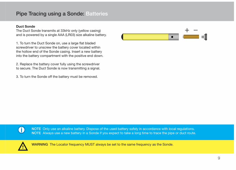
Duct Sonde
The Duct Sonde transmits at 33kHz only (yellow casing) and is powered by a single AAA (LR03) size alkaline battery.
1. To turn the Duct Sonde on, use a large flat bladed screwdriver to unscrew the battery cover located within the hollow end of the Sonde casing. Insert a new battery into the battery compartment with the positive end down.
2. Replace the battery cover fully using the screwdriver to secure. The Duct Sonde is now transmitting a signal.
3. To turn the Sonde off the battery must be removed.
Pipe Tracing using a Sonde: Batteries
9
NOTE Only use an alkaline battery. Dispose of the used battery safely in accordance with local regulations.NOTE Always use a new battery in a Sonde if you expect to take a long time to trace the pipe or duct route.
WARNING The Locator frequency MUST always be set to the same frequency as the Sonde.
+ -----

The technique used to determine the position of a Sonde is always the same irrespective of which Sonde is being used.
Before inserting the Sonde into the pipe it is best to set up the Locatorso that the Sensitivity is correctly adjusted to suit the pipe depth. This is much easier to do when the Sonde is visible at the bottom of the manhole rather than already some distance up the pipe.
The blade of the Locator must be held IN LINE with the Sonde at all times.
1. Turn the Locator to Generator/ Transmitter Mode, switch on and select the correct frequency. Check the Battery Level Indicator to confirm the Locator batteries are usable. Replace if necessary.
2. Keeping the blade of the Locator in line with the Sonde, move the Locator backwards and forwards over the length of the Sonde. Adjust the Sensitivity until a clear peak response is shown on the display as the Locator passes directly over the position of the Sonde.
Still keeping the blade of the Locator in line with the Sonde, now movethe Locator from side to side over the position of the Sonde. A similarpeak response should be seen on the display as the Locator passes directly over the position of the Sonde. The Locator is now set up readyfor tracing the Sonde.
3. Push the Sonde up the pipe.
Pipe Tracing using a Sonde: Tracing a Sonde
10
NOTE This is at 90degrees to the way in which the Locator is held for most other locating tasks.
2.

4. With the Locator turned on, walk from the pipe access point in the direction that the Sonde was pushed. A strong peak signal directly over the Sonde should be detected with two lesser ‘ghost’ signals found, one in front of and one behind the Sonde’s true position.These ghost signals are always weaker than the main signal and should not be mistaken for the true Sonde signal.
5. Pinpoint the Sonde’s exact position by moving the Locator first backwards and forwards and then from side to side to get the peak response on both occasions.
6. Push the Sonde further up the pipe and repeat the pinpointing process.
See Page 14 for depth measurement using a Sonde.
Signal Generator/ Transmitter Accessories: Tracing a Sonde
11
4.
7 3 7

The Plastic Pipe Tracers and Flexible Tracer can be used in small diameter non-metallic pipes that normal Sondes cannot fit into. Two methods of detecting and tracing can be used: line tracing and end tracing.
For Line Tracing, the Plastic Pipe Tracer needs to be inserted into the pipe before a signal from the Signal Generator/ Transmitter is applied to the length of the Tracer. The slip-ring mechanism of the Flexible Tracer allows a Signal Generator/ Transmitter to be connected before it is inserted into the pipe.
The 33kHz, CF or 131kHz Signal Generator/ Transmitter signal is applied using the ‘Direct Connection to a metal pipe’ method as shown in the Locator Instruction Manual. Connect the red Direct Connection Lead to the red terminal of the Plastic Pipe Tracer/Flexible Tracer. Connect the black lead to the Earth Stake. Leave the other terminal of the Plastic Pipe Tracer/ Flexible Tracer unconnected.
Non-Metallic Pipe Tracing: Plastic Pipe Tracers/ Flexible Tracer
12
NOTE It is important that a change of pitch is heard when making the connections to ensure that there is a detectable signal present on the Tracer.NOTE The Signal Generator/ Transmitter signal is unlikely to travel the entire length of the Tracer within the pipe. Never assume that you have located the end of the Tracer on Line Tracing Mode. Use End Tracing if required. NOTE The Plastic Pipe Tracer and Flexible Tracer can be used inside a metal pipe or duct but the signal will transfer onto the pipe or duct itself.
WARNING Authorisation may be required before using the Plastic Pipe Tracer/ Flexible Tracer on some pipes or ducts.WARNING DO NOT touch the metal of the Crocodile Clips or the terminals of the Plastic Pipe Tracer when using the Signal Generator/ Transmitter.

End Tracing
The very tip of the Plastic Pipe Tracer/Flexible Tracer can be energised withthe signal from a Signal Generator/Transmitter. It is acting much like aSonde and offers a very reliable way of pinpointing the position of the tip.Pipes and ducts up to 4metres (13 foot) deep can be traced (Locator dependent).
A 33kHz or CF Signal Generator/ Transmitter signal is applied by connecting the red Direct Connection Lead to the red terminal on the Tracer and the black Earth Lead to the other terminal. As the second connection is made a change of pitch should be heard from the Signal Generator/ Transmitter signal indicating successful connection.
The tip of the Plastic Pipe Tracer/ Flexible Tracer is then pinpointed using the same technique as for Sonde tracing with the Locator blade always in line with the Tracer.
Non-Metallic Pipe Tracing: Plastic Pipe Tracers/ Flexible Tracer
13
NOTE It is important that a change of pitch is heard when making the connections to ensure that there is a detectable signal present on the Tracer.NOTE End Tracing is the ideal method to use to determine where the end of the pipe is but does not give the route of the pipe.NOTE The Plastic Pipe Tracers and Flexible Tracer do not work on End Tracing mode inside a metal pipe or duct.
WARNING Authorisation may be required before using the Plastic Pipe Tracer/ Flexible Tracer on some services.WARNING DO NOT touch the metal of the Crocodile Clips or the terminals of the Plastic Pipe Tracer/ Flexible Tracerwhen using the Signal Generator/ Transmitter.

1. Pinpoint the exact position of the Sonde or Plastic Pipe Tracer/ Flexible Tracer tip. Take care to ensure that you are not over one of the two ‘ghost’ signals in front of and behind the true position.
2. Rest the Locator on the ground, keeping it vertical and IN LINE with the Sonde or Tracer tip.
3. IMPORTANT.
Push the depth button TWICE and hold on the second push, to select Sonde Depth Mode.
The word ‘SONDE’ will flash on the display and the depth will then be displayed (see picture).
If the word ‘SONDE’ is not displayed then the depth reading will not be accurate.
Depth Measurement: Error Readings
The Locator may show the following error codes when attempting a Depth Measurement.
1. 000 - The Sonde/Plastic Pipe Tracer/ Flexible Tracer is too shallow for the Locator to obtain an accurate depth, less than 0.20m (8 inches). Or 0.8m (31 inches) for the Cable Avoidance Tool XD and DXL3 Cable Avoidance Tool.It should be possible to calculate the depth by raising the Locator a set amount and then carrying out the Depth Measurement again.
2. 888 - The Sonde/Plastic Pipe Tracer/ Flexible Tracer is too deep for the Locator to measure its depth or there is no signal at all present.
3. L0 - The signal from the Sonde/Plastic Pipe Tracer/ Flexible Tracer is not strong enough for the Locator to give a reliable depth measurement.
4. OL - Overload. The signal from the Sonde/Plastic Pipe Tracer/ Flexible Tracer is too strong for the Locator to give a reliable depth measurement.
Depth Measurement using Sonde or Plastic Pipe Tracer/Flexible Tracer (end tracing only)
14
NOTE The following instructions apply equally to all Sondes, the Plastic Pipe Tracer and the Flexible Tracer in End Tracing Mode.
NOTE The depth shown is that of the Sonde and NOT of the pipe.
Note. Metric version shown.

5
General Symbols
15
GEnERAL SYMboLS
Warning - Refer to manual.
Waste electrical products should not be disposed of with household waste. Please recycle where facilities exist. Check with your local authority or retailer for recycling advice. (In the UK visit www.recycle-more.co.uk)
Conforms to EC safety requirements.
Tested to harmonised standards. Some restrictions on use in some EC countries. Contact Local Authorities.
Double Insulated.
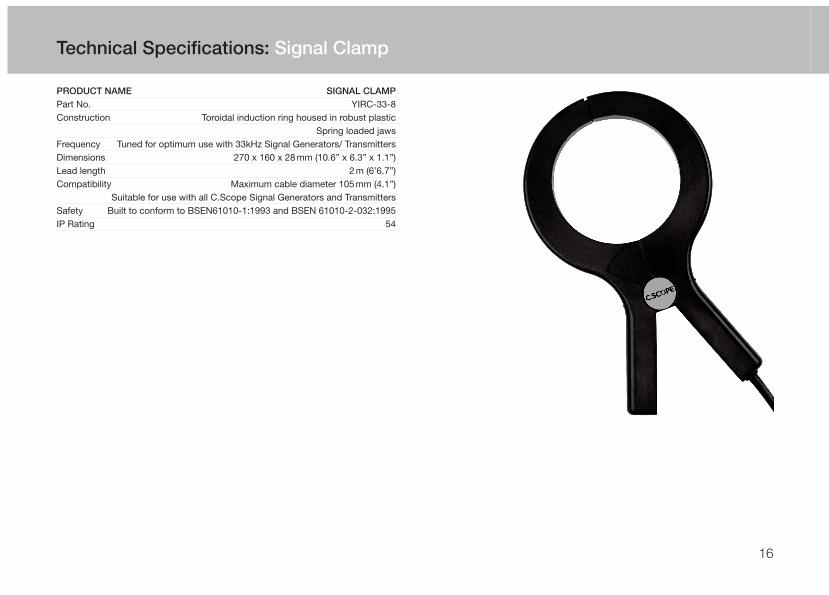
PRODUCT NAME SIGNAL CLAMP
Part No. YIRC-33-8Construction Toroidal induction ring housed in robust plastic Spring loaded jawsFrequency Tuned for optimum use with 33kHz Signal Generators/ TransmittersDimensions 270 x 160 x 28mm (10.6” x 6.3” x 1.1”)Lead length 2m (6’6.7”)Compatibility Maximum cable diameter 105mm (4.1”) Suitable for use with all C.Scope Signal Generators and TransmittersSafety Built to conform to BSEN61010-1:1993 and BSEN 61010-2-032:1995IP Rating 54
16
Technical Specifications: Signal Clamp

PRODUCT NAME SIGNAL INjECTOR
Part No. YIRIP-33-8 and YIRIP-33E Dimensions:Box 100 x 50 x 25mm (3.9” x 1.9” x 1”)Input Lead Length 1m (3’3.3”)Output Lead Length 1.5m (4’11”)Construction Encapsulated, robust housing Moisture / dust resistant to IP54Electrical Output (Mains side):Electrical Isolation Class II (Double Insulated)Maximum Voltage 250 V rmsMaximum Load <10mA (predominantly capacitive)Frequency range 45-65HzMains Plug Connector: UK, 3 pin to BS1363, load between Live and Earth (YIRIP-33-8) or 2 pin European Shuko style (YIRIP-33E)Electrical Input (Signal Generator/ Transmitter side):Connector 3 pin XLR male (industry standard)Maximum Voltage 42 V rmsMaximum Power <250mW when driven from C.SCOPE Signal Generator/ TransmitterInput Impedance 2000OhmsFrequency 32,768HzSafety Built to conform to BSEN61010-1:1993 and BSEN 61010-2-032:1995
17
Technical Specifications: Signal Injector

PRODUCT NAME 33kHz GENERAL PURPOSE SONDE
Part Numbers YIRS-33Frequency Transmits 32,768HzConstruction Rugged plastic casing, stainless steel stud. Epoxy resin filledColour Orange casing for 33kHzDetection Depth Range Up to 7m (23 foot) (dependent on type of C.SCOPE Locator and site conditions)
Dimensions 39mm diameter x 121mm long (1.5” x 4.7”)End fitting M10 threaded stud Supplied with Rod Connector to fit standard drain rods with 7 T.P.I. threadBattery Type Single AA, LR6 AlkalineBattery Life Up to 15 hoursApprovals EN301 489 EN300 330
IP Rating 68
PRODUCT NAME 8kHz GENERAL PURPOSE SONDE
Part Numbers YIRS-8Frequency Transmits 8,192HzConstruction Rugged plastic casing, stainless steel stud. Epoxy resin filledColour Green casing for 8kHzDetection Depth Range Up to 7m (23 foot) (dependent on type of C.SCOPE Locator and site conditions)Dimensions 39mm diameter x 121mm long (1.5” x 4.7”)End fitting M10 threaded stud Supplied with Rod Connector to fit standard drain rods with 7 T.P.I. threadBattery Type Single AA, LR6 AlkalineBattery Life Up to 15 hoursApprovals EN301 489 EN300 330
IP Rating 68
Technical Specifications: General Purpose Sondes 8kHz/33kHz
18

PRODUCT NAME METAL PIPE SONDE
Part Numbers YIRS-512 and YIRS-640Frequency Transmits 512Hz and 640Hz respectivelyDetection Depth Range Up to 5metres (16’5”) dependent on pipe material and wall thickness
Dimensions 39mm diameter x 121mm length (1.5” x 4.7”)End fitting M10 threaded stud supplied with 7 t.p.i. rod fitting (other adaptors are available)Battery Type 1 x AA (IEC type LR6) Battery Life Up to 25 hours intermittent use at 20ºC (68ºF)Approvals EN301489 EN300 330 EAN 5060086350791IP Rating: 68
PRODUCT NAME DUCT SONDE 33kHz
Part No. YIRSD-33Construction Waterproof, robust plastic O Ring battery compartment seal, stainless steel end fittingsFrequency Transmits 32,768Hz continuousDetection Depth Range 4.5m (15’) dependent on type of C.SCOPE Locator and site conditionsDimensions 24mm diameter x 200mm length (1” x 7.8”)End fitting Standard rod thread (" Whitworth 16 T.P.I.) female connector at one endBattery Type 1 x AAA (IEC type LR03) Alkaline typically giving Battery Life Up to 20 hours intermittent use at 20ºC (68ºF)IP Rating 68
Technical Specifications: Metal Pipe Sonde/ Duct Sonde
19

20
PRODUCT NAME 20M AND 50M PLASTIC PIPE TRACER
Part No. YIRPPT20-33 and YIRPPT50-33Frequency Operates at 32,768HzDetection Depth Range: Line Detection 3m (10’) Tip Detection 4m (13’) (dependent upon Locator and Signal Generator type and site conditions)Compatibility Any Signal Generator or Transmitter with 33kHz or 33/131kHz combined output
Rod Length 20m or 50m (65’ and 160’)Rod and Sonde Diameter 6mm (0.2”)Rod Minimum Bend Radius 50mm (1.9”)Construction:Reel Robust plastic housingRod Flexible, chemical resistant plasticReel dimensions (20m) 150 x 120 x 250mm (5.9” x 4.7” x 9.8”)Reel dimensions (50m) 165 x 290 x 240mm (6.5” x 11.4” x 9.4”)Reel weight (20m) 1248g (2 pound 12 ounces)Reel weight (50m) 2073g (4 pound 8.5 ounces)
Operational Temperature Range -20ºC to 50ºC (-4ºF to 122ºF)Storage Temperature Range -20ºC to 50ºC (-4ºF to 122ºF)IP rating for actual Tracer Rod & Tip 68IP rating for Plastic Pipe Tracer Casing 54
Technical Specifications: Plastic Pipe Tracers

21
PRODUCT NAME 80 M FLExIBLE TRACER
Part No. YIRRFT-80Frequency Optimised for 32,768HzDetection Depth Range: Line Detection 3m (10 foot) Tip Detection 4m (13 foot) (dependent upon Locator and Signal Generator type and site conditions)Compatibility Any Signal Generator or Transmitter with 33kHz or 33/131kHz combined outputRod Length 80m (260’)Rod Diameter 5mm nominal (0.2”)Rod Material Quality sleeved fibreglass rod with three integral copper wiresRod Minimum Bend Radius 10cm (3.9”) reducing to 15cm (5.9”), 5cm (1.9”) from TipRod wire diameter 0.45mm each wire (0.018”)Transmitting Sonde Diameter 7.5mm max. (0.3”)Rigid Tip Length 20mm max. (0.8”)Tip Material BrassFrame Size 58.8 x 28.8 x 48.5cm (1’11” x 11.3” x 1’7”)Frame Material Powder coated 16mm steel tube (0.6”)Reel Diameter 48cm (1‘7”)Weight 7.5kg (16 pound 8.5 ounces)Slip ring assembly Sealed multi-wire duplexedOperational Temperature Range -20ºC to 50ºC (-4ºF to 122ºF)Storage Temperature Range -20ºC to 50ºC (-4ºF to 122ºF)IP rating for Tracer Rod & Tip 68IP rating for Casing 54IP rating for Terminal Box 66
Technical Specifications: Flexible Tracer
22
Maintenance
Maintenance
All C.Scope accessories must be visually inspected for any signs of deteriation prior to each use. Do not use if there is any deteriation.
There are no user serviceable parts for these Accessories.
Handling
All C.Scope accessories are rugged products designed for the rigours of every day use. However, to ensure that the specified performance is maintained, it is essential to treat them with care by avoiding shocks, vibration and excesses of temperature. They are not guaranteed to prevent water ingress if immersed with the exception of all Sondes.
Cleaning
The equipment can be cleaned with a sponge dampened with warm water. A mild soap may be used if required. The use of solvents should be avoided.
Do not allow moisture in the battery compartments or near the connectors.
Storage
The equipment should be stored in a clean and dry environment.The temperature should not exceed the range -10˚C to +50˚C(14˚F to +122˚F). If stored for long periods the batteries shouldbe removed.

23
Training
This manual is comprehensive but cannot replace tuition. Excellent training is available directly from C.Scope and via authorised C.Scope agents, cost effectively, at your chosen location. C.Scope always recommend operators are trained and awarded a certificate of competence in the use of Pipe and Cable Locators.
Servicing
Routine periodic servicing and re-calibration of your equipmentis available from C.Scope and C.Scope Authorised Service Centres if required.
Repairs
Before returning equipment suspected of being faulty, please check the machine carefully with a fresh set of batteries. Check the battery connections and rotate the batteriesin the holder. Refer to the section in the manual on functionalchecks and if possible substitute known good equipment as a confirmation.
If the problem persists then contact the company from whomyou purchased the equipment, or contact C.Scope stating the serial number, date and place of purchase and indicatingbriefly the nature of the fault. Advice on the best course of action can then be given.
Support Services: Training/Servicing/Repairs

C.Scope International Ltd
Kingsnorth Technology ParkWotton RoadAshfordKent TN23 6LNUnited Kingdom
Telephone. +44(0)1233 629181Fax. +44(0)1233 645897email. [email protected]. www.cscopelocators.com
CSCOPE Accessories Instruction Manual - Part no. B1080 Issue 3