lock-n-loadtm - · pdf fileraise the ram approximately 2" and place block under sub ......
TRANSCRIPT

Lock-N-LoadTM
Auto Progressive (AP) Reloading Press
With EZject™ System.

- 1 - - 2 - - 1 -
Table of ConTenTs
Steps Page Overview 2 Tools needed for assembly and set up 2 1: Mounting the Lock-N-Load Auto Progressive 3 2: Determine which shell plate is required for your application 4 2A: Installing the Shell Plate 5 2B: Removing the Shell Plate 6 3: Operation of your Lock-N-Load Auto Progressive Press 8 4: Automatic Primer Feed Assembly 9 4A: Installing the Primer Body 9 4B: Installing the Primer Slide, Large or Small 9 4C: Installing the Primer Punch Assembly, Large or Small 9 4D: Installing the Primer Tubes 9 4E: Installing the Primer Tube Housing 9 4F: Primer Tube Support Installation 10 5: Loading the Primer Tube 11 6: Changing Primer Tubes 12 7: Automatic Primer Feed Inspection 13 8: Installing the Deluxe Powder Measure with Case Activated Powder Drop 13 9: Lock-N-Load quick change bushing system 14 10: Die Mounting Instructions 15 11: Preparing to Load 16 12: Adjusting the Auto Advance Mechanism 17 Maintenance of the Lock-N-Load A/P 19 Tips for a Trouble Free Operation 19 Optional Accessories for your L-N-L AP 20
List of Illustrations
Figures 1. AP Mounting 3 2. Installing Shell Plate 5 3. Removing Shell Plate 6 4. Primer Feed System 10 5. Filling the Priming System 11 6. Lock-N-Load Powder Measure 13 7. Hornady Lock-N-Load System 14 8. Pawl Adjustment 17 Charts 1. Shell Plate Selection Chart 4 2. Trouble Free Operation 19 3. Bill of Materials 21 4. Exploded View 22

- 1 - - 2 - - 1 -
Hornady®
Lock-N-Load Auto Progressive
Your new Lock-N-Load Auto Progressive (A/P) reloading press has been packaged to insure minimal vibration and damage during transportation.
Remove all the parts from the packing box and spread them out over a large flat surface. Refer to the parts list on pages 21 and 22 and check to make sure all necessary parts are identified.
The manual provides step-by-step instructions and suggestions that make set-up and operation easy and understandable.
If at any time during operation you feel like you are forcing the press, stop and identify the problem. Do not force anything, because damage will occur. Powders and Primers are explosive if handled carelessly! Always work slowly and carefully without distractions and wear eye protection. Try to avoid touching primers with oily fingers. The oil on your fingers may contaminate the primers and cause them to misfire.
Tools needed for assembly and set-up:7⁄16" End Wrench(2) 1⁄2" End Wrenches15 ⁄16" End Wrench3⁄32" Hex Wrench (included)1/8" Hex Wrench (included)5 ⁄32" Hex WrenchNeedle Nose PliersElectric Drill5/16" Hex Wrench
overview

- 3 - - 4 - - 3 -
Step 1: Mounting the Lock-N-Load Auto Progressive
Your work area should be well lit and have plenty of room for your reloading accessories. Your Hornady Lock-N-Load AP should be mounted securely 2 1/4 " from the edge of a solid level bench. (Check for obstruc-tions on or below the bench before you drill any holes.)
Mount the press using (2) 5/16" bolts that are long enough to secure the press to the bench with plenty of clearance for the nuts. (Due to variation of benches these bolts are not provided.) We also recommend using 5/16" flat washers top and bottom, in addtion to lock washers on the bottom side.
Insert and secure the right-hand mounting bolt first. Next, insert and secure the left-hand bolt, placing the cartridge catcher bracket (13) underneath the bolt head and washer before tightening.
Thread the press Handle (44) into the Toggle (39) at the bottom of the press and tighten the Jam Nut (43) using a 15/16" wrench.
Figure 1: AP Mounting
insTruCTions
5/16 FLAT WASHER
5/16 BOLT
TOGGLE (39)
JAM NUT (43)
CARTRIDGE CATCHER BRACKET (13)

- 3 - - 4 - - 3 -
Step 2: Determine which shell plate is required for your application
See Chart 1 below to help with this selection.
* Hornady shell plates that are sold in the plastic boxes are the only ones that will fit the AP Press with EZject™ System. These shell plates (which are sold separately) are manufactured with a groove on the bottom side.
SHELL PLATE NO. 1Item No. 392601
5.6x5722/250 Rem22-250 Ack Imp240 Wby.243 Win.244/6MM Rem6MM Int.6MM/2846MM Rem Br250 Sav..25/06 Rem257 Rbts..25/284260 Rem6.5 Rem Mag6.5/066.5 x 576.5/2846.5 Creedmoor270 Win.7x57 (7MM mau.)7MM/087MM Rem. BR7x647MM Exp/280280 Rem280 Rem Ack Imp284 Win.300 Sav.308 Win.30 TC30/06 Springfield338 Federal7.7 Jap.7.92x33MM Kurz8MM Mau.8MM /068x60 S338-0635 Whelen358 Win.9.3x579.3x62400 Cor-bon44 Auto Mag.45 Win Mag458 SOCOM.450 Bushmaster
SHELL PLATE NO. 2Item No. 392602
219 Zipper5.6x52R22 Sav. HP25/35 Win7x30 Waters30/30Win30/30 Ack Imp30 Herrett32 Win. Spl.8.15x46 R357 Herrett38-55 Win375 Win7.5 Swiss32/40 Win357 Herrett38-55 Win375 Win7.5 Swiss32/40 Win
SHELL PLATE NO. 3Item No. 392603
22 Hornet22-K Hornet270 Rem
SHELL PLATE NO. 4Item No. 392304
220 Swift225 Winchester6.5 JDJ7MM Merrill30MM Merrill
SHELL PLATE NO. 5Item No. 392605
257 Wby. Mag.6.5 Rem. Mag.264 Win. Mag.270 Wby. Mag. 7MM Rem. Mag.7MM Rem SA Ultra Mag.7MM Wby. Mag.7MM Rem. Ultra Mag.7MM STW300 H&H300 Win. Mag.300 Wby. Mag.300 Rem. SA UI. Mag.300 Rem. UI. Mag308 Norma Mag.8MM Rem. Mag.338 Win. Mag.338 Rem. Ultra Mag.
340 Wby. Mag.350 Rem. Mag.358 Norma Mag.375 Rem. Ultra Mag.375 H&H416 Rem. Mag.458 Win.450 Marlin300 RCM338 RCM375 Ruger416 Ruger458 Lott
SHELL PLATE NO. 6Item No. 392606
22 PPC22 RCFM-Jet256 Win.6MM PPC7.62x3938/357/357 Max.
SHELL PLATE NO. 7Item No. 392607
218 Bee25/20 Win.32/20 Win.
SHELL PLATE NO. 8Item No. 392608
30 Luger30 Mauser9MM Luger9x219x18 Makarov38 Super Auto9x23
SHELL PLATE NO. 9Item No. 392609
38/40 Win. 44/40 Win.
SHELL PLATE NO. 10Item No. 392610
357 Sig40 S&W10MM Auto
SHELL PLATE NO. 11Item No. 392611
303 British30/40 Krag
SHELL PLATE NO. 12Item No. 392612
25 Rem.6.8 Rem. SPC30 Rem.32 Rem.
SHELL PLATE NO. 13Item No. 392613
7X65 R7x57 R9.3x74 R
SHELL PLATE NO. 14Item No. 392614
30/378 Wby. Mag.33 Win.338/378 Wby.378 Wby. Mag.416 Wby. Mag.460 Wby. Mag.45/70 Govt.480 Ruger/475 Linebaugh
SHELL PLATE NO. 16Item No. 392616
17 Rem.17 Rem. Fireball 17/22217/223220 VT 20 Tactical204 Ruger221 Rem.222 Rem.222 Rem. Mag.5.6x50 Mag223 Rem.6MM/2236x47 Rem6MM TCU6.5MM TCU7MM TCU7MM/223 Ingram7x47 Helm380 Auto
SHELL PLATE NO. 19Item No. 392619
6.5 x 55 Scand (Swedish)
SHELL PLATE NO. 22Item No. 392622
5.7 Johnson Spitfire30 M1 Carbine32 ACP
SHELL PLATE NO. 23Item No. 392623
7.62 Russian
SHELL PLATE NO. 27Item No. 392627
308 Marlin Express309 JDJ375 JDJ444 Marlin
SHELL PLATE NO. 28Item No. 392628
38 S&W
SHELL PLATE NO. 29Item No. 392629
41 Mag
SHELL PLATE NO. 30Item No. 392630
6.5x688x68 S357/44 B&D44 Spl./44 Mag.445 Sup Mag7.5 Swiss
SHELL PLATE NO. 31Item No. 392631
45 Auto Rim
SHELL PLATE NO. 32Item No. 392632
45 Colt454 Casull
SHELL PLATE NO. 33Item No. 392633
303 Sav.307 Win.356 Win.
SHELL PLATE NO. 35Item No. 392635
223 WSSM243 WSSM25 WSSM270 WSSM7x61 S&H7MM WSM300 WSM325 WSM
SHELL PLATE NO. 36Item No. 392636
32 S&W Long/Short/H&R
SHELL PLATE NO. 40Item No. 392640
50 A&E
SHELL PLATE NO. 44Item No. 392644
500 S&W
SHELL PLATE NO. 45Item No. 392645
45 ACP (ONLY)
SHELL PLATE NO. 46Item No. 392646
460 S&W
SHELL PLATE NO. 51Item No. 392651
455 Webley
TOP SIDE BOTTOM SIDE
Hornady Shell Plates are sold
separately.
shell PlaTes

- 5 - - 6 - - 5 -
2: Installing the Shell Plate
Raise the Ram approximately 2" and place Block under Sub Plate (24). This disengages the Index Pawls (32), and allows for free rotation of the Shell plate.
Put a small amount of general-purpose grease on the Shell Plate Ball Detents located on bottom side of Shell Plate (12), and on the top surface of the Sub-Plate (24).
Align the Shell Plate* with the keyed Drive Hub (29).
Place the 3/8" Shell Plate Retainer Bolt (9) thru the 3/8" Flat Washer (28), (large end up) and thread the bolt into the Drive Hub (29).
Tighten the bolt (9) using a 5/16" Allen wrench, only tight enough to prevent it from coming loose.
Stretch the Case Retainer Spring (17) over the top of the Shell Plate (12).
Remove Block from under Sub-Plate (24) and make sure it is in the Retainer Spring Grove (17A).
While cycling the Press, push the Case Retainer Spring (17) into the relieved area on the Sub-Plate (24). You will have to cycle the press a couple of stations to receive these results.
Figure 2: Installing Shell Plate
SHELL PLATE RETAINER BOLT (9)
SHELL PLATE (12)
DRIVE HUB (29)
SUB PLATE (24)
RETAINER SPRING-GROOVE (17A)
EZject
FLAT WASHER (28)
- 5 - - 6 - - 5 -
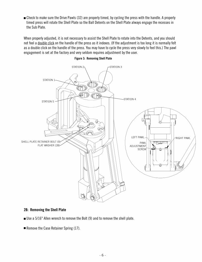
Check to make sure the Drive Pawls (32) are properly timed, by cycling the press with the handle. A properly timed press will rotate the Shell Plate so the Ball Detents on the Shell Plate always engage the recesses in the Sub Plate.
When properly adjusted, it is not necessary to assist the Shell Plate to rotate into the Detents, and you should not feel a double click on the handle of the press as it indexes. (If the adjustment is too long it is normally felt as a double click on the handle of the press. You may have to cycle the press very slowly to feel this.) The pawl engagement is set at the factory and very seldom requires adjustment by the user.
2B: Removing the Shell Plate
Use a 5/16" Allen wrench to remove the Bolt (9) and to remove the shell plate.
Remove the Case Retainer Spring (17).
Figure 3: Removing Shell Plate
SHELL PLATE RETAINER BOLT (9)FLAT WASHER (28)
STATION 1
STATION 2
STATION 5STATION 4
STATION 3
LEFT PAWL RIGHT PAWL
PAWL ADJUSTMENT
SCREW

- 7 - - 8 - - 7 -
If the timing is severely out of adjustment, the Index Pawls (32) may have been damaged as outlined on page 6.
If the Shell Plate does not rotate freely after mounting, check for these conditions:
• You may be trying to use the wrong version of shell plate. Your shell plate must have a groove cut on the bottom side.
• Dirt or debris between the shell plate and the drive hub.• The Ball Detent bodies are not below flush on the underside of the Shell Plate.• The Shell Plate is warped or damaged.
If you reach a point where you cannot get the press to work, please call our technical service staff at 800-338-3220 or email [email protected].
shell PlaTe TroubleshooTing

- 7 - - 8 - - 7 -
Step 3: Operation of your Lock-N-Load Auto Progressive Press
The Hornady Lock-N-Load AP utilizes a high strength aluminum alloy frame with a compound linkage system which operates the 2" diameter cylindrical ram. The Ram houses a drive shaft that is attached to the shell plate at the upper end and the index wheel at the lower end. The toggle contains two spring actuated pawls which alternately engage the index wheel to advance the shell plate through the different reloading stations.
As the handle is lowered, the right Pawl contacts the Index Wheel, advancing the Shell Plate during the first 1 1/2" of upward travel of the Ram. With this upward travel, the cases become aligned with the dies at the top of the Press. As the Shell Plate comes to the top of the press, it guides the cartridge cases into the five die stations to perform the reloading operations except priming.
The handle is then raised to complete the stroke, lowering the Shell Plate. When the Shell Plate comes to within 1 3/4" of the bottom, the left Pawl engages the Index Wheel which advances the Shell Plate into position over the primer to seat it into the case that was just sized and de-primed. Pushing back on the handle with moderate force will seat the new primer into the case.
Once the dies are in place, and all stations are filled, the proper sequence for reloading is listed below.
Place an empty case into station one. (Using the optional LNL-AP Casefeeder, this step is automatically done for you.)
Insert bullet into the powder charged case in station four.
Lower the handle.
Powder drops into the newly primed case at station three.
Raise the handle and seat a new primer in the de-primed case that has now moved to station two.
Loaded cartridge is automatically ejected at station five when handle is raised.

- 9 - - 10 - - 9 -
Step 4: Automatic Primer Feed Assembly
4A: Installing the Primer Body.
Place the aligning pin, located on the underside of the Primer Body (14) in the hole on the Sub-Plate (24) located next to the Primer Slide (15).
Insert the cap screw (11) thru the hole of the Primer Body (14) and screw it into the Sub-Plate (24).
Rotate the Primer Body (14) Counter Clock Wise (CCW) towards the loader against the bolt and tighten the bolt.
4B: Installing the Primer Slide, Large or Small
Lower the handle (44).
Place a 2" spacer under the Sub-Plate (24). A 4" section of a 2" wide wooden block works well.
Place the Primer Slide (15) (flat side up) in the groove on the Sub-Plate (24) and slide forward. The bump on the bottom side of the slide is the travel stop as well as an alignment guide while the slide is in the retracted position.
Attach the Spring (16) to the Sub-Plate (24) with the open end up (you may need to use needle nose pliers). Attach the other end of the Spring to the pin on the Primer Slide.
4C: Installing the Primer Punch Assembly, Large or Small
Raise the Ram (37) to the top of the stroke.
Screw the Primer Seater Punch (26) into the Sub-Plate (24) from the bottom side.
Tighten the Primer Seater Punch assembly (26) until it is snug using a wrench. (Do not over tighten the Primer Punch)
4D: Installing the Primer Tubes
Place the tube of your choice (large or small primers) (4 or 5) in the center hole of the Primer Body (14) with the shoulder section of the tube facing down. Make sure the tube is fully seated in the Primer Body.
4E: Installing the Primer Tube Housing
Slip the threaded end of the Primer Tube Housing (6) over the Primer tube (4 or 5) and onto the Primer Body (14).
Screw the Primer Tube Housing (6) on to the Primer Body (14) Clock Wise (CW). Snug the tube by hand.

- 9 - - 10 - - 9 -
4F: Primer Tube Support installation
Place the Primer Tube Support (1) over the Primer Tube (4 or 5) and slip the three Tapered “Fingers” inside the Primer Tube Housing (6). This will create a recess that allows the Primer Filler Tube (2 or 3) to properly align with the Primer Feeder tube during refillings.
Figure 4: Primer Feed System
PRIMER SEATER PUNCH (26)
SUB-PLATE (24)PRIMER BODY (14)
PRIMER SLIDE (15)
CAP SCREW (11)ALIGNING PIN
SPRING (16)
SUB-PLATE (24)
PRIMER SLIDE (15)
PRIMER BODY (14)
(10)
PRIMER TUBE SUPPORT (1)
PRIMER FEED TUBE (4 or 5) “SHOULDERED END DOWN”
PRIMER FEED TUBE (4 or 5) “SHOULDERED END DOWN”
PRIMER FEED TUBE (4 or 5) “SHOULDERED END DOWN”
PRIMER BODY (14)
- 11 - - 12 - - 11 -
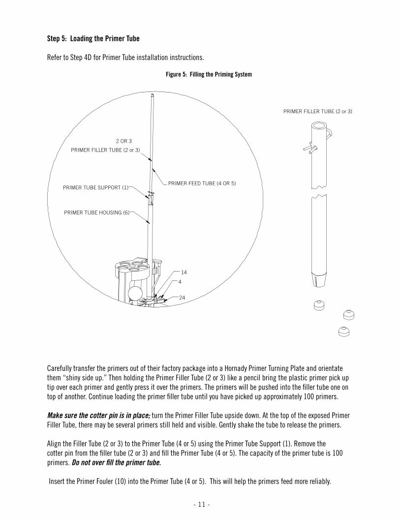
Step 5: Loading the Primer Tube
Refer to Step 4D for Primer Tube installation instructions.
Carefully transfer the primers out of their factory package into a Hornady Primer Turning Plate and orientate them “shiny side up.” Then holding the Primer Filler Tube (2 or 3) like a pencil bring the plastic primer pick up tip over each primer and gently press it over the primers. The primers will be pushed into the filler tube one on top of another. Continue loading the primer filler tube until you have picked up approximately 100 primers.
Make sure the cotter pin is in place; turn the Primer Filler Tube upside down. At the top of the exposed Primer Filler Tube, there may be several primers still held and visible. Gently shake the tube to release the primers.
Align the Filler Tube (2 or 3) to the Primer Tube (4 or 5) using the Primer Tube Support (1). Remove the cotter pin from the filler tube (2 or 3) and fill the Primer Tube (4 or 5). The capacity of the primer tube is 100 primers. Do not over fill the primer tube.
Insert the Primer Fouler (10) into the Primer Tube (4 or 5). This will help the primers feed more reliably.
Figure 5: Filling the Priming System
2 OR 3
PRIMER FEED TUBE (4 OR 5)
PRIMER TUBE HOUSING (6)
PRIMER TUBE SUPPORT (1)
24
4
14
PRIMER FILLER TUBE (2 or 3)
PRIMER FILLER TUBE (2 or 3)

- 11 - - 12 - - 11 -
Step 6: Changing Primer Tubes
When changing to a different size of primer, you need to change the Primer Tube ( 4 or 5), Primer Slide (15) and Punch Assembly (26).
If there are primers in the Primer Feed Tube you will need to empty it before changing the tubes. Remove the Cap Screw (11), hold your cupped hand under the Primer Tube and rotate the Primer Feed Body Assembly (CW) to catch the primers. After the tube is empty, rotate the body back in place and re-install the mounting screw. Refer to Step 4 for more details. Disconnect the primer feed spring from the roller pin and remove the Primer Slide Assembly (15). Remove the Primer Tube Support (1) and the Primer Tube (4 or 5).
If the primer tube is empty, there is no need to take the primer feed assembly off of the sub-plate. Remove the Primer Feed Support (1), Primer Tube (4 or 5), disconnect the Primer Feed Spring (16) and remove the Primer Slide (15) and Punch Assembly (26). Reinstall the primer system for your application (Refer to Step 4). Fill the primer tube as previously described (Refer to Step 5).
The Primer Punches (26) are installed from the bottom side of the Sub-Plate (24). Raise the Ram (37) to the top of the stroke. Use a wrench to loosen the Primer Punch (26) and unscrew it from the Sub-Plate (24). When installing a new Primer Punch (26), tighten it snug with a wrench. Do not over tighten the Primer Punch.
PRIMER SEATER PUNCH (26)
SUB-PLATE (24)PRIMER BODY (14)
PRIMER SLIDE (15)
CAP SCREW (11)ALIGNING PIN
SPRING (16)
SUB-PLATE (24)
PRIMER SLIDE (15)
PRIMER BODY (14)
(10)
PRIMER TUBE SUPPORT (1)
PRIMER FEED TUBE (4 or 5) “SHOULDERED END DOWN”
PRIMER FEED TUBE (4 or 5) “SHOULDERED END DOWN”
PRIMER FEED TUBE (4 or 5) “SHOULDERED END DOWN”
PRIMER BODY (14)

- 13 - - 14 - - 13 -
Step 7: Automatic Primer Feed Inspection
It is not necessary to install the primer tubes at this time to test your loader, but you must install the Primer Body (14). Lower the Prmer Slide so that is stays in place. See step 4A for instructions on installing the Primer Body (14).
At this point you should have installed a Shell Plate and the corresponding Primer Seater Punch (26) and Primer Slide (15) for the cartridge for which you are loading.
Step 8: Installing the Lock-N-Load Powder Measure with Case Activated Powder Drop.
The Lock-N-Load Powder Measure combines with the Case Activated Powder Drop to mount on-top of the Lock-N-Load A/P in station 2 or 3. The L-N-L Powder Measure that was shipped with the press has been factory fitted with the case activiated Powder Drop.* This press comes packaged with the Standard Rotor & Standard Metering Insert and the Pistol Rotor & Pistol Metering Insert.
Refer to the Lock-N-Load Powder Measure and Case Activated Powder Drop instructions for cleaning and functionality. (These instructions are included).
Figure 6: Lock-N-Load Powder Measure
UPPER ASSEMBLY
MEASURE ADAPTER
STATION 1
STATION 2

- 13 - - 14 - - 13 -
Step 9: Lock-N-Load quick change bushing system
The Lock-N-Load system is based on the positive locking action of the bolt action rifle. Just like the bolt action rifle, the locking action is incredibly strong and simple.
Once the dies and the powder measure are adjusted for loading, these settings are locked in place by tighten-ing the Lock Ring that is provided with all Hornady dies and powder measures.
How the Lock-N-Load works:
Insert the Lock-N-Load bushing into the press and turn it Clock Wise (CW) to lock it in place.
Adjust the die to the desired position and lock the setting in place with the die’s lock ring.
Once Lock-N-Load bushings are installed, Dies and Powder Drop can be removed from the press with a quick counterclockwise (CCW) turn. Since the Lock-N-Load bushing is locked in place, the dies and the Powder Drop remain set exactly as you left them.
For added speed and convenience, Hornady offers inexpensive Quick Change Powder Dies for use with the Case Activated Powder Drop.
Figure 7: Hornady Lock-N-Load System
LOCK-N-LOAD BUSHING/RECPTACLE
LOCK-N-LOAD BUSHING
LOCK RING
LOCK-N-LOAD BUSHING THREADS ONTO STANDARD 7/8"-14 TPI RELOADING DIES.

- 15 - - 16 - - 15 -
Step 10: Die Mounting Instructions
For initial die cleaning and set-up instructions, please refer to the instruction sheet that came with your die set.
Please Note: The Hornady Lock-N-Load Auto Progressive with EZject™ System can use any brand of die.
Hand loading is very safe, but before reloading any case please read the following warnings.
Primers may explode if subjected to impact or heat.
Keep away from the opening end of the Primer Tube at all times.
Variations may occur with different brands and condition of cartridge cases, which can cause inconsistent primer and bullet seating. Sort and inspect all of your cases before reloading.
Verify your powder charges at frequent intervals to insure consistency.
Careless or improper hand loading techniques can result in serious personal injury. Make sure there are no distractions while you are reloading.
Before operating this press, be sure you have read and understand all the instructions contained in this manual, and that you understand the principals of hand loading.

- 15 - - 16 - - 15 -
Step 11: Preparing to Load
To begin reloading, start with a single empty cartridge case and run it through all of the loading stations (see Step 3 for details). This will allow you to check your adjustments. Refer to instructions provided with the die set for set up and proper adjustment.
Sizing a case.• Make sure the sizing die is adjusted properly, and the de-priming pin knocks out the old primer.
Seating a primer.• Check and make sure the Primer Slide (15) picked up a primer from the Primer Tube (4 or 5).• When you cycle the press and the handle comes to a stop, you will have to push the handle away from you
past the stop to seat the primer. Push until it stops but don’t force it. Seating the primer requires a firm push.
• Lower the handle of the press slowly to rotate the shell plate to start the next operation. If there is resistance on the shell plate, the primer is improperly seated and not allowing the Shell Plate to rotate.
Drop powder in the case using the case activated powder drop.• Verify the weight on a properly calibrated scale.
Seat a bullet in the powder charged case.• Begin lowering the handle to rotate the shell plate to this station.• Place a bullet on top of the case and lower the handle the rest of the way. (You may need to position the
bullet over the case neck between your thumb and forefinger until the bullet enters the alignment sleeve).
Station 5. (Refer to illustration on page 6.)• This station is used for a Taper Crimp Die when reloading pistol cartridges that headspace off the
case mouth. * Any manufacturer’s Taper Crimp Die will work in Station 5 with the AP’s EZject™ System.• Properly adjusted, a taper crimp die removes all case-flare from the expander die without damaging or
squeezing into the bullet.
Next, lower the handle, advance the shell plate to the next station. The loaded round will rotate and contact the EZject™ System underneath the shell plate. This EZject™ System will automatically eject the loaded round from the press. Never force the handle. Measure the case for proper length and check it against the data in your reloading book.
Once you are satisfied with the first completed cartridge, repeat the process with another single case, advancing slowly from station to station until you eject the finished cartridge from the press with the case ejector.
After you are comfortable, load the press with consecutive cases for reloading. Do not rush! After you advance the cases through each station, inspect everything to insure proper function at each station. If anything looks out of place, or if you lose track of what you are doing, STOP! Remember, it’s safer to begin slowly than it is to assume you need to reload a large number of cartridges during each session. Don’t force the handle at any time, and be sure that all mechanical parts are properly lubed.
SAFETY NOTE: Be safe! Double check your powder loads at frequent intervals to insure the powder charge is working properly.

- 17 - - 18 - - 17 -
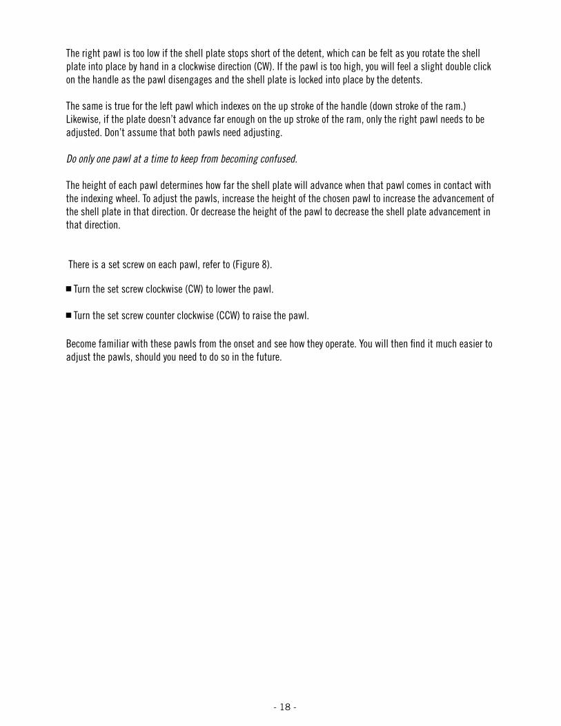
Step 12: Adjusting the Auto Advance Mechanism
The Auto Advance Mechanism is fully adjusted at the Hornady factory and should not require further adjustment. In the event that you feel your shell plate is not advancing properly, check all other options listed in this manual before attempting to adjust the mechanism’s pawls.
All adjustments should be made in extremely small increments.
Through everyday use, the pawls on your press may gradually wear and may need to be adjusted to compensate for this wear. Before making adjustments, you should understand what each pawl does.
As the operating handle is lowered and raised through a complete cycle, each pawl in turn engages the index wheel at the bottom of the press. The index wheel is connected through the driveshaft to the shell plate. As each pawl engages the index wheel it advances the shell plate either at the top or bottom of the cycle.
The right pawl (as you face the press) advances the shell plate as the ram travels up when the handle is pulled down. The left pawl advances the wheel on the down stroke of the handle and should advance the shell plate to the detent holes in the sub-plate. If the shell plate doesn’t advance enough on the down stroke of the ram, only the left pawl needs adjustment.
Figure 8: Pawl Adjustment
RIGHT PAWL (32)
PAWL ADJUSTMENTSCREW
LEFT PAWL (32)
- 17 - - 18 - - 17 -
The right pawl is too low if the shell plate stops short of the detent, which can be felt as you rotate the shell plate into place by hand in a clockwise direction (CW). If the pawl is too high, you will feel a slight double click on the handle as the pawl disengages and the shell plate is locked into place by the detents.
The same is true for the left pawl which indexes on the up stroke of the handle (down stroke of the ram.) Likewise, if the plate doesn’t advance far enough on the up stroke of the ram, only the right pawl needs to be adjusted. Don’t assume that both pawls need adjusting.
Do only one pawl at a time to keep from becoming confused.
The height of each pawl determines how far the shell plate will advance when that pawl comes in contact with the indexing wheel. To adjust the pawls, increase the height of the chosen pawl to increase the advancement of the shell plate in that direction. Or decrease the height of the pawl to decrease the shell plate advancement in that direction.
There is a set screw on each pawl, refer to (Figure 8).
Turn the set screw clockwise (CW) to lower the pawl.
Turn the set screw counter clockwise (CCW) to raise the pawl.
Become familiar with these pawls from the onset and see how they operate. You will then find it much easier to adjust the pawls, should you need to do so in the future.

- 19 - - 20 - - 19 -
As with all machinery, proper routine maintenance will provide smooth operation and a longer life for your reloading press. Check all moving parts for dirt or spilled powder and remove with a clean shop rag.
Remove the primer slide, shell plate and clean the spilled powder under it. After cleaning, lubricate the sub-plate in the area of the detents, drive hub and sub-plate with one or two drops of light grade machine oil or Hornady One Shot Gun Cleaner and Dry Lube. The primer slide is permanently lubricated and needs no oil.
Lightly lube the index wheel, and pawls. Hornady One Shot Gun Cleaner and Dry Lube is excellent here. It is a dry lube, so stray powder won’t stick to it while you’re reloading.
Problems soluTions
Powder dropping around case Correct bushing in place? Powder drop tube and measure adapter clean? Bushing installed deep counter sink side up?
No primer in case Primer slide properly adjusted? Correct primer punch installed? Primer slide spring in place? Correct Primer Slide installed? Primer Body rotated CCW when installed?
Shell Plate will not advance or does not index on station
Primer not fully seated? Pawls correctly adjusted? Make sure you have the latest shell plate version with the groove on the bottom side.
Cases do not feed into Dies Die mouths beveled? (if not, return to manufacturer for repair.) Pawls timed correctly?
Gun Powder is sticking in the powder measure, or inconsistent charge weights
Is the inside surface dry and clean?Try pouring a little powdered graphite thru the powder measure for lubricant. Rub the outside of the powder hopper with a dryer sheet to eliminate static.
Case retainer spring won’t fall off the shell plate or it is getting kinked
Is there a burr on the shell plate where the spring groove and the case location meet? Is there a burr on the sides of the slot on the sub-plate? (With a casefeeder, when you are setting up the timing do not run the case into the spring if the spring is up on the shell plate.)
mainTenanCe of The loCk-n-load a/P
TiPs for Trouble-free oPeraTion

- 19 - - 20 - - 19 -
oPTional aCCessories for your loCk-n-load aP
The Case Activated Powder Drop has been engineered with quick change-overs in mind. The retainer spring offers smooth function and the powder drop only dispenses a powder charge when a case is present. Works with the L-N-L AP or other progressive presses that use 7/8" x 14 threads. No. 050073
Designed specifically for use with our Case Activated Powder Drop, this accessory makes changing over your L-N-L AP faster and easier than ever! It allows you to preset dies for the quickest caliber conversion on the market. Includes lower bracket with guide bushing and lock ring.
Our Powder Through Expanders (above) work great with the Quick Change Powder Die. No. 050074
Powder Through Expanders (PTX) are designed to work in conjunction with the Case Activated Powder Drop, these new Expanders eliminate the need for a separate case mouth expander die on the L-N-L AP progressive press (Hornady suggests you fill that station with the powder cop die, so you can ensure that each case is properly charged with powder.)
.355 . . . . . . .No. 290040 .357 . . . . . . .No. 290041
.400 . . . . . . .No. 290042 .430 . . . . . . .No. 290043
.451/452 . . . .No. 290044 .475 . . . . . . .No. 290045
.500 . . . . . . .No. 290048
* For use with Case Activated Powder Measure only.
Simply thread a Hornady Lock-N-Load™ Conversion Kit into your RCBS® Rock Chucker or other reloading press using a 1¼-12 thread, and you’re ready to start using the Lock-N-Load™ System. It’s the easiest way to get the most out of your reloading press. These bushings let you take advantage of Hornady’s Lock-N-Load™ technology even if you own a competitive reloading press. The Lock-N-Load™ Conversion kit includes three die bushings and one conversion bushing.
Lock-N-Load Press Conversion Bushings . .No. 044095 (2-pk.) Lock-N-Load Die Bushings . . . . . . . .No. 044094 (3-pk.) Lock-N-Load Die Bushings . . . . . . . .No. 044093 (10-pk.) Lock-N-Load Die Bushings . . . . . . .No. 044096 Lock-N-Load Conversion Kit . . . . . . . . . . . . .No. 044099
Install on your progressive press after the powder drop station to automatically check dropped charges. Checking powder charges on your progressive press can be difficult, and is sometimes ignored, even though it’s a smart practice. Hornady uses a similar device on our own ammo manufacturing presses. It won’t replace careful attention, but helps monitor the reloading process. Works with all powder types and calibers. No. 050063
CASE ACTIVATED POWDER DROP
HORNADy POWER COP
QuICK CHANgE POWDER DIE
POWDER THROugH ExPANDERS
LOCK-N-LOAD™ DIE AND CONVERSION BuSHINgS

- 21 - - 22 - - 21 -
bill of maTerials
“We guarantee every one of our reloading tools and accessories for Life”No-Risk, Lifetime Warranty
Hornady reloading tools and accessories are warranted against material defects and workmanship for the life of the products. Parts which by nature of their function are subject to normal wear such as springs, pins, bearings, etc… and, parts which have been altered, abused, or neglected are excluded for the warranty.
If the product is deemed defective by either workmanship or material, the reloading tool or accessory will either be repaired, reconditioned or replaced at Hornady Manufacturing Company’s option. If it breaks, we’ll repair it or replace it at no charge.
To return a product call toll free, (800) 338-3220 and ask for Customer Service. They will provide instructions for return, if the problem can’t be solved over the phone. Prices and or specifications are subject to change without notice. For the best prices on any of our products, contact your nearest Hornady dealer.
Hornady Manufacturing Company cannot assume liability for damage which may result from use of the products or information given herein, since Hornady had no control over the manner in which its products or components are used during reloading.
ITEM NO.
PRODUCTION PART NO.
QTY. DESCRIPTION ITEM NO.
PRODUCTION PART NO
QTY. DESCRIPTION
1 398318 1 SUPPORT PRIMER TUBE 26 398507 1 PRIMER SEATER PUNCH LARGE
2 398356 1 TUBE PRIMER PICKUP LARGE 27 392467 1 SPRING COUNTER BALANCE
3 398355 1 TUBE PRIMER PICKUP SMALL 28 392345 1 3/8 FLAT WASHER SS
4 398358 1 TUBE PRIMER LARGE 29 392355 1 DRIVE HUB
5 398357 1 TUBE PRIMER SMALL 30 392356 1 DRIVE SHAFT
6 398322 1 HOUSING TUBE PRIMER 31 392231 2 SCREW BHSCS 8-32 X 3/8
7 392220 1 SCREW BHCS 1/4-20 X 1/2 32 392344A 2 PAWL
8 392202 1 BRACKET LNLAP 33 392423 2 SPRING PAWL
9 392342 1 SHCS SS 3/8-16 X 3/4 34 392306 2 DOWL PIN 1/8 X 1/2
10 398359 1 PRIMER FOLLOWER 35 392221 2 SCREW FHCS 1/4-28 X 3/8
11 392338 1 SCREW SHCS 10-24 X 1/2 36 290029 1 SPENT PRIMER TUBE
12 39226_ 1 SHELL PLATE 37 392359 1 RAM
13 392455 1 BRACKET BOX CARTRIDGE 38 398422 3 GREASE ZERK™
14 398319A 1 HOUSING BODY PRIMER TUBE 39 392343 1 TOGGLE
15 392218 1 PRIMER SLIDE LARGE ASSY. 40 392340 1 PIN YOKE
15 392219 PRIMER SLIDE SMALL ASSY. 41 392424 5 SPRING WASHER
16 392336 1 SPRING PRIMER SLIDE 42 392417 2 PIN LINK TOGGLE
17 392363 1 SPRING CASE RETAINER 43 390027 1 NUT JAM 5/8-18
18 392210 1 CAM FEED PRIMER 44 390657 1 HANDLE
19 392011 2 NUT NEX 10-32 45 480003 1 KNOB
20 190216 1 FRAME 46 392357 1 YOKE
21 392368 6 CLIP C C-50 47 392358A 1 INDEX WHEEL
22 480039 1 BOX CATCHER 48 390081 2 CLIP E 1/2
23 392408 2 LINK LNLAP 49 392302 5 LOCK-N-LOAD BUSHING MALE
24 398309T 1 SUB PLATE 50 392203 5 LOCK-N-LOAD BUSHING O-RING
25 390410 1 SCREW FHCS 1/4-28 X 3/8 51 392365 1 SPENT PRIMER TUBE PLASTIC26 398505 1 PRIMER SEATER PUNCH SMALL 52 392301 5 LOCK-N-LOAD BUSHING FEMALE
53 398715 1 WASHER

- 21 - - 22 - - 21 -
1 2 3
4 5
6
7
89
10
11
12
13
1415
16 17 1819
20 21
22
23
24
252627 2930
3132
33
3435
36
37
38
39
40
41
42 43
44
45
46
47
48
49
5051
28
eXPloded view

10/31/08 780307A
P.O. Box 1848 • Grand Island, NE 68802-1848(308) 382-1390 • www.hornady.com