locomotive crashworthiness research · nsn 7540-01-280-5500 standard form 298 (rev. 2-89)...
TRANSCRIPT

Locomotive Crashworthiness Research
U.S. Department of Transportation Federal Railroad Administration
Office of Research Volume 2: Design Concept Generation and Development and Evaluation Washington, DC 20590
Research and Special Programs Administration
Volpe National Transportation Systems Center Cambridge, MA 02142-1093
DOT/FRA/ORD-95/08.2 Final Report This document is available to the public through the National DOT-VNTSC-FRA-95-4.2 July 1995 Technical Information Service, Springfield, VA 22161

NOTICE
This document is disseminated under the sponsorship of the Department of Transportation in the interest of information exchange. The United States Government assumes no liability for its contents or use thereof.
NOTICE
The United States Government does not endorse products or manufacturers. Trade or manufacturers' names appear herein solely because they are considered essential to the objective of this report.

REPORT DOCUMENTATION PAGE Form Approved OMB No. 0704-0188
Public reporting burden for this collection of information is estimated to average 1 hour per response, including the time for reviewing instructions, searching existing data sources, gathering and maintaining the data needed, and completing and reviewing the collection of information. Send comments regarding this burden estimate or any other aspect of this collection of information, including suggestions for reducing this burden, to Washington Headquarters Services, Directorate for Information Operations and Reports, 1215 Jefferson Davis Highway, Suite 1204, Arlington, VA 22202-4302, and to the Office of Management and Budget, Paperwork Reduction Project (0704-0188), Washington, DC 20503. 1. AGENCY USE ONLY (Leave blank)
2. REPORT DATE July 1995
3. REPORT TYPE AND DATES COVERED Final Report
October 1994 – January 1995
4. TITLE AND SUBTITLE
Locomotive Crashworthiness Research Volume 2: Design Concept Generation and Evaluation
6. AUTHOR(S)
Ronald A. Mayville, Richard G. Stringfellow, Robert J. Rancatore, Thomas P. Hosmer
5. FUNDING NUMBERS
R5001/RR528
7. PERFORMING ORGANIZATION NAME(S) AND ADDRESS(ES) Arthur D. Little, Inc. Acorn Park Cambridge, MA 02140-2390
8. PERFORMING ORGANIZATION REPORT NUMBER
DOT-VNTSC-FRA-95-4.2
9. SPONSORING/MONITORING AGENCY NAME(S) AND ADDRESS(ES) U.S. Department of Transportation Research and Special Programs Administration Volpe National Transportation Systems Center Kendall Square, Cambridge, MA 02142-1093
10. SPONSORING/MONITORING AGENCY REPORT NUMBER
DOT/FRA/ORD-95/08.2
11. SUPPLEMENTARY NOTES This research is sponsored by the Federal Railroad Administration, Office of Research and Development, Washington, DC 20590
12a. DISTRIBUTION/AVAILABILITY STATEMENT
This document is available to the public through the National Technical Information Service, Springfield, VA 22161
12b. DISTRIBUTION CODE
13. ABSTRACT (Maximum 200 words)
This is the second volume in a series of four that reports on a study in which computer models were developed and applied to evaluate whether various crashworthiness features, as defined in Public Law 102-365, can provide practical benefit to the occupants of freight locomotives. In particular, the benefit was assessed relative to the current industry standard, S-580. This report includes a description of: (1) the crashworthiness concepts generated in the program; (b) the occupant survivability model employed; and (c) the approach and results of the evaluation. The baseline crash scenario that was used for calculations is described. Also presented are the effects of each concept on short hood crush and secondary impact injury potential, and estimates of cost and weight for the various concepts. Stronger collision posts, crash refuges, and shatterproof windows are among the concepts studied.
15. NUMBER OF PAGES
62
14. SUBJECT TERMS
Rail vehicle; Transportation; Safety; Locomotive crashworthiness; Collisions; Structural analysis; Dynamics analysis
16. PRICE CODE
17. SECURITY CLASSIFICATION OF REPORT
Unclassified
18. SECURITY CLASSIFICATION OF THIS PAGE
Unclassified
19. SECURITY CLASSIFICATION OF ABSTRACT
Unclassified
20. LIMITATION OF ABSTRACT
Unlimited
NSN 7540-01-280-5500 Standard Form 298 (Rev. 2-89) Prescribed by ANSI Std. 239-18 298-102

PREFACE
In September 1992, the Congress passed Public Law 102-365, the Railroad Safety
Enforcement and Review Act, which required, in part, that the Secretary of Transportation
conduct research and analysis to consider the costs and benefits of several types of
crashworthiness improvement features.
This report presents several concepts for improving the crashworthiness of road freight locomotive cabs. The effectiveness of each concept in limiting cab intrusion is evaluated and
its influence on occupant survivability is assessed. The work was carried out by Arthur D. Little, Inc., under contract to the Volpe National Transportation Systems Center, from January
3, 1994, to March 31, 1995. The work was conducted as part of the Center's support to the
Office of Research and Development, Federal Railroad Administration.
This is the second of four volumes. Volume 1 covers model development and validation. Volume 3 discusses the pros and cons, and summarizes the estimated costs versus benefits, for each of the represented crashworthiness improvement features. Volume 4 extends the
modeling to additional effects, and the analysis to higher closing speeds.
During the course of the study, further work was assigned to provide for additional studies of
selected freight locomotive crashworthiness improvement features in collisions at higher closing speeds and for evaluation of the crashworthiness of the cabs in control cars used in
passenger service. The additional freight locomotive studies will appear as volume 4 of this
series. The work on control car cabs will be published as a separate report.
iii

METRIC/ENGLISH CONVERSION FACTORSENGLISH TO METRIC METRIC TO ENGLISH
LENGTH (APPROXIMATE) LENGTH (APPROXIMATE)
1 inch (in) = 2.5 centimeters (cm) 1 millimeter (mm) = 0.04 inch (in)
1 foot (ft) = 30 centimeters (cm) 1 centimeter (cm) = 0.4 inch (in)
1 yard (yd) = 0.9 meter (m) 1 meter (m) = 3.3 feet (ft)
1 mile (mi) = 1.6 kilometers (km) 1 meter (m) = 1.1 yards (yd)
1 kilometer (km) = 0.6 mile (mi)
AREA (APPROXIMATE) AREA (APPROXIMATE)
1 square inch (sq in, in2) = 6.5 square centimeters(cm2)
1 square centimeter (cm2) = 0.16 square inch (sq in, in2)
1 square foot (sq ft, ft2) = 0.09 square meter (m2) 1 square meter (m2) = 1.2 square yards (sq yd,yd2)
1 square yard (sq yd, yd2) = 0.8 square meter (m2) 1 square kilometer (km2) = 0.4 square mile (sq mi, mi2)
1 square mile (sq mi, mi2) = 2.6 square kilometers(km2)
10,000 square meters (m2) = 1 hectare (ha) = 2.5 acres
1 acre = 0.4 hectare (he) = 4,000 square meters (m2)
MASS - WEIGHT (APPROXIMATE) MASS - WEIGHT (APPROXIMATE)
1 ounce (oz) = 28 grams (gm) 1 gram (gm) = 0.036 ounce (oz)
1 pound (lb) = 0.45 kilogram (kg) 1 kilogram (kg) = 2.2 pounds (lb)
1 short ton = 2,000 pounds(lb)
= 0.9 tonne (t) 1 tonne (t) =
=
1,000 kilograms (kg)
1.1 short tons
VOLUME (APPROXIMATE) VOLUME (APPROXIMATE)
1 teaspoon (tsp) = 5 milliliters (ml) 1 milliliter (ml) = 0.03 fluid ounce (fl oz)
1 tablespoon (tbsp) = 15 milliliters (ml) 1 liter (l) = 2.1 pints (pt)
1 fluid ounce (fl oz) = 30 milliliters (ml) 1 liter (l) = 1.06 quarts (qt)
1 cup (c) = 0.24 liter (l) 1 liter (l) = 0.26 gallon (gal)
1 pint (pt) = 0.47 liter (l)
1 quart (qt) = 0.96 liter (l)
1 gallon (gal) = 3.8 liters (l)
1 cubic foot (cu ft, ft3) = 0.03 cubic meter (m3) 1 cubic meter (m3) = 36 cubic feet (cu ft, ft3)
1 cubic yard (cu yd, yd3) = 0.76 cubic meter (m3) 1 cubic meter (m3) = 1.3 cubic yards (cu yd, yd3)
TEMPERATURE (EXACT) TEMPERATURE (EXACT)
[(x-32)(5/9)] °°F = y °°C [(9/5) y + 32] °°C = x °°F
QUICK INCH - CENTIMETER LENGTH CONVERSION10 2 3 4 5
Inches
Centimeters 0 1 3 4 52 6 1110987 1312
QUICK FAHRENHEIT - CELSIUS TEMPERATURE CONVERSION -40° -22° -4° 14° 32° 50° 68° 86° 104° 122° 140° 158° 176° 194° 212°
°F
°C -40° -30° -20° -10° 0° 10° 20° 30° 40° 50° 60° 70° 80° 90° 100°
For more exact and or other conversion factors, see NIST Miscellaneous Publication 286, Units of Weights and Measures. Price $2.50 SD Catalog No. C13 10286 Updated 6/17/98

TABLE OF CONTENTS
Section Page 1. INTRODUCTION .............................................…………………………………………………………1-1 2. DESIGN CONCEPT GENERATION AND EVALUATION APPROACH ......…………………………2-1
2.1 Information Gathering ..................................………………………………………………….. 2-1 2.2 Design Concept Generation .......................………………………………………........…….... 2-2 2.3 Design Concept Crashworthiness Evaluation …………………………….. ..................……..... 2-3
3. OCCUPANT SURVIVABILITY MODEL ......………………………………….…...............……...... 3-1
3.1 Overview .............................................……………………………………………………….. 3-1 3.2 ATB Model Description .....................………………………………………………………. ..... 3-1 3.3 Model Description and Occupant Response Predictions ....……………………………......…. 3-2 3.4 Occupant Survivability Measures ........…………………………………….........…….......... 3-4
4. BASELINE CRASH SCENARIO .............………………………………………………................... 4-1
4.1 Overview .....................................…………………………………………….…….......…..... 4-1 4.2 Description .............................................…………………………………………….……..... 4-1 4.3 Model Application ..................................…………………………………….………….……... 4-1
5. CRASHWORTHINESS CONCEPTS …….. ........…………………………………………….…............ 5-1
5.1 Overview ..................…………………………………………………….........……............... 5-1 5.2 Collision Posts ...........……………………………………………….............….................... 5-1 5.3 Anticlimbers/Uniform Sill Heights .....…………………………………….....…....................... 5-5 5.4 Crash Refuges ..........................................……………………………………………….…… 5-12 5.5 Rollover Protection Devices .................................……………………………………………..5-19 5.6 Deflection Plates ........................................………………………………………………….5-21 5.7 Shatterproof Windows .....................................………………………………………………….5-26 5.8 Equipment To Deter Post-Collision Entry of Flammable Liquids ..………………………….......... 5-28
6. SUMMARY .................................................... ………………………………………………...……... 6-1
REFERENCES ................................................………………………………………...…………………. R-1
v

LIST OF FIGURES
Figure Page
2-1. Overview of the Crashworthiness Modeling Approach ………………………………........................ 2-4
3-1. Typical Baseline Cab/Occupant Model: Top View ...…………………………………....................... 3-3
3-2. Probability of Head Trauma as a Function of the Head Injury Criterion …...…………………........... 3-6
3-3 Probability of Thoracic Trauma as a
Function of Resultant Chest Acceleration ..................…………………………………………........ 3-6
4-1. Data Derived from the Accident Report Used
to Formulate the Baseline Crash Scenario ................…………………………...……………......... 4-2
4-2. Photograph of the Lead Locomotives in
the Baseline Crash Scenario Accident ..............…………………………………………................ 4-3
4-3. The Load-Crush Curve Computed and Idealized for the Baseline
Coupler/Draft Gear Support Structure/Underframe Elements ......…………………………….......... 4-4
4-4. The Load-Crush Curves Computed and Idealized
for the Baseline Anticlimber/Underframe Element ..….......…………………………………........... 4-4
4-5. The Load-Crush Curve Computed and Idealized for the
Baseline Short Hood Structure/Collision Posts Element ...……………………….………................. 4-5
4-6. The ADAMS Model View of the Lead Locomotives in the
Baseline Crash Scenario at the Point of Maximum Crush ....……………………………….............. 4-7
4-7. The Locomotive Cab Crash Pulse for the Baseline Crash Scenario ..………...………………......... 4-7
5-1. Finite Element Mesh Depiction of the Concept Collision Post ......…………………………….......... 5-3
5-2. Calculated Load-Crush Curve for the Concept Short Hood/Collision Posts (2) Element .............….....………………………………………...........5-3
5-3 The Cab Crash Pulse for the Concept Collision Post Locomotive …....………………………........ 5-4
5-4. Finite Element Mesh of the Anticlimber Modeled to Satisfy S-580 Requirements ....................…..………………………………………..... 5-7
5-5. Illustration of the Interlocking Anticlimber Concept ..…..……………………………….................. 5-9
5-6. Cab Crash Pulse for the Interlocking Anticlimber Concept Locomotive .………………………...... 5-11
vi

LIST OF FIGURES (continued)
Figure Page
5-7. Illustration of the Rotating Seat Crash Refuge Concept .......…………………………………......... 5-13
5-8. Illustration of the Trench Crash Refuge Concept .................………………………………………... 5-14
5-9. Occupant Position in the Rotate and Lock Seat Crash Refuge Concept ………………………….... 5-16
5-10. Occupant Position in the Rotate, Lock, and Drop Crash Refuge Concept .…………………………. 5-16
5-11. Occupant Position in the Trench Crash Refuge Concept ..........…………………………………...... 5-17
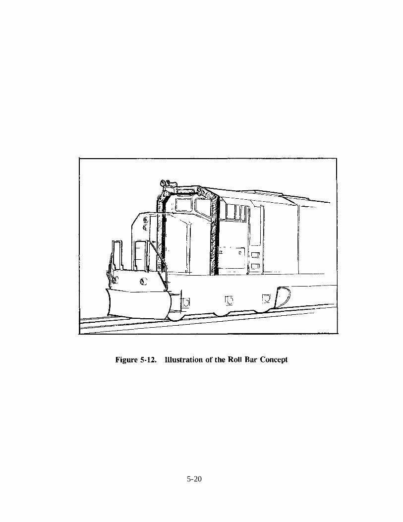
5-12. Illustration of the Roll Bar Concept ................………………………………………………............ 5-20
5-13. Design Crash Loads for the Roll Bar Concept .………………………………………....................... 5-22
5-14. Illustration of the Deflection Plate Concept ......………………………………………….................. 5-24
5-15. Results of the ADAMS Model Applied to
the 45-Degree Deflection Plate Concept ..........……………………………………………............... 5-25
vii

LIST OF TABLES
Table Page
1-1. Summary of AAR's S-580 Standard on
Locomotive Crashworthiness Requirements ..........….…………………...……………………............. 1-1
2-1. Site Visits Made to Gather Information
on Locomotive Design and Fabrication .........……………………………………………….................. 2-1
2-2. List of Concepts Selected for Detailed Evaluation
for Each of the Features Listed in the Public Law ………………………………………....................... 2-2
3-1. Selected Biomechanical Measures of Occupant Survivability ......…………………………………...... 3-4
4-1. Locomotive Cab Occupant Response to the Baseline Crash Scenario ..……………………………....... 4-8
5-1. Locomotive Cab Occupant Response for the Collision Post Concept ..….……………………………... 5-5
5-2. Locomotive Cab Occupant Response for the Interlocking Anticlimber .……………………………..... 5-10
5-3. Estimates of Weight and Cost Increase Over the Baseline Locomotive
for the Three Crash Refuge Concepts Analyzed in this Study .......………………………………….... 5-15
5-4. Locomotive Cab Occupant Response for the
Crash Refuge Concepts (Baseline Crash Pulse) ..…………………………………………................... 5-18
5-5. Locomotive Cab Occupant Response for the Crash
Refuge Concepts (Interlocking Anticlimber Crash Pulse) .……………………………………............5-19
5-6. Glazing Options ............................………………………………………………………....…......….5-27
6-1. Summary of Crashworthiness Concept Evaluation Results ......…………………………………....….. 6-2
viii

1. INTRODUCTION
Arthur D. Little and its subcontractors, Arvin/Calspan and Parsons Brinckerhoff, conducted
studies of locomotive crashworthiness in support of the Federal Railroad Administration's
(FRA) response to Public Law 102-365. This law includes a statement that the Secretary of
Transportation shall conduct research and analysis to consider the costs and benefits
associated with equipping locomotives with the following crashworthiness features:
• Braced collision posts
• Crash refuges
• Rollover protection devices
• Uniform sill heights
• Deflection plates
• Anticlimbers
• Shatterproof windows
• Equipment to deter post-collision entry of flammable liquids
The Arthur D. Little team was awarded a contract to conduct engineering analyses to identify
and evaluate various design concepts for the features described above. In particular, the team
was asked to perform this evaluation with respect to the currently applied Association of
American Railroads industry standard, S-580, summarized in table 1-1. This standard applies
to new road type locomotives built after August 1, 1990.
Table 1-1. Summary of AAR's S-580 Standard on Locomotive Crashworthiness
Requirements
Components Requirement
Anticlimbers Sustain an ultimate vertical load of 200,000 lbf at the short hood end
Collision posts Two, each of which shall sustain an ultimate load of 200,000 lbf at 30 inches above the deck and 500,000 lbf at the deck
Short hood structure The product of skin thickness and yield strength shall be at least 0.5 inches times 25,000 psi
The overall approach to the project included information gathering on locomotive design and
crashworthiness; the development of computer models to evaluate crashworthiness; and the
generation, evaluation, and prioritization of design concepts that could potentially improve
locomotive cab survivability. No testing was included in the program. Rather, models were
validated to the extent possible by comparing predicted results to actual accidents.
This report describes the freight locomotive crashworthiness concepts generated in the project, together with their evaluation using computer models whose development and validation were
described in volume 1 [1].
1-1

The objective of this particular part of the project was to identify and study specific
crashworthiness concepts corresponding to each of the features listed in the Public Law. We
sought to determine whether practical improvement to cab crashworthiness is feasible and, where apparently feasible , to specify the concept in terms of performance rather than detailed
designs (volume 3).
This report is organized into sections describing: the overall approach to concept generation
and evaluation (section 2); the occupant survivability computer model (section 3); the baseline
crash scenario used for evaluation of the concepts (section 4); each concept together with the
results of the evaluation (section 5); and an overall summary of the results (section 6).
Prioritization of the design concepts together with relevant discussion are presented in
volume 3. Volume 4 extends the modeling to additional effects and the analysis to higher closing speeds.
1-2

2. DESIGN CONCEPT GENERATION AND EVALUATION APPROACH
2.1 INFORMATION GATHERING
A substantial effort carried out in this study was the acquisition of information that could be
useful to us both in identifying existing and generating new crashworthiness concepts, and in
establishing the practical constraints for such concepts. This activity included literature
searches, telephone discussions with industry personnel, and visits to locomotive-related
facilities. The literature review extended back to the 1970s when a substantial effort was put into the crashworthiness subject (c.f. [2], [3]). Table 2-1 lists the locomotive-related facility
visits made during this study along with the purpose of each visit.
Table 2-1. Site Visits Made to Gather Information on Locomotive Design and
Fabrication
Site Purpose
Conrail, Acquaint the entire team with freight Boston, Massachusetts locomotives
Conrail Locomotive Repair Station, Observe locomotive structures and
Altoona, Pennsylvania types of collision damage; obtain
opinions on crashworthiness design
EMD Engineering Facility, Obtain information on locomotive
LaGrange, Illinois design constraints and crashworthiness
design
EMD Fabrication Facility, Observe locomotive fabrication and
London, Ontario basic structure
GE Engineering and Fabrication, Obtain information on locomotive
Erie, Pennsylvania design constraints and crashworthiness
design; observe locomotive fabrication
and basic structure
Our effort also included extensive study of accident reports, including a visit to the site — within 48 hours — of the head-on collision in Marathon, Texas, in July 1994. Some of the accident information collected is reported in volume 1 because it also served to validate the collision computer models.
2-1

2.2 DESIGN CONCEPT GENERATION Several concept generation meetings were held between members of the project team to develop candidate ideas for the various crashworthiness features. Participants in these meetings consisted primarily of design engineers and staff associated with the railroad environment. The core team that had visited the various locomotive facilities also participated. In general, a list of eight to fifteen ideas were generated for each feature. From these the participants selected the two or three felt to be most likely to yield practical benefit. The next step in the process was to prepare layout drawings and to investigate initial structural, cost, and fabrication issues with the top candidate concepts to further establish feasibility. An overall meeting was then held with the core team to select the candidate concept for each feature felt to yield the most practical benefit. One concept was selected for each feature except crash refuge, for which three were finally selected. These are listed in table 2-2; detailed descriptions of the concepts are provided in section 5. In general, the criteria used for selecting various concepts were qualitative and based on three considerations: likely effectiveness in providing benefit to the crew; increase in weight; and increase in cost. Crashworthiness effectiveness included considerations of ability to protect, reliability, and likelihood of use (for crash refuges). Weight increases were considered to be small if they were under 1000 lb and large if they were over 10,000 lb; current locomotive weights are on the order of 280,000 for four-axle and 400,000 for six-axle locomotives. Added costs were considered large if they exceeded about $10,000; the current cost of a freight locomotive ranges from about $1.5 to $2 million in 1994 dollars.
Table 2-2. List of Concepts Selected for Detailed Evaluation for Each of the Features
Listed in the Public Law
Public Law Feature Concept Investigated Goal
Braced collision posts Collision post with flanges Reduce cab crush in override mode
Rollover protection Roll bar at front of cab Reduce cab crush from top and
devices side loads
Deflection plates Angled plates integral with Deflect lead, oncoming vehicle to
anticlimber the side
Shatterproof windows Advanced materials Increase penetration and spall resistance
Crash refuges Rotating, reinforced seat Provide an area for the occupants
Rotating, reinforced drop seat to ride down the collision
Rear cab trench
Uniform sill heights Interlocking anticlimber Promote interaction between
colliding underframes
Anticlimbers Interlocking anticlimber Prevent override
Equipment to deter Reinforced cab openings Reduce possibility of creating cab post-collision entry openings in a collision
of flammable liquids
2-2

Once the final concepts were selected, rough designs were developed which were then used to
generate several pieces of information: (1) the load-deformation (crush) curve, where relevant, using finite element analysis to generate the response needed for the collision dynamics
model; (2) weight; and (3) the cost of parts and fabrication, obtained primarily through quotes
from various vendors.
2.3 DESIGN CONCEPT CRASHWORTHINESS EVALUATION
The effect of each concept on crashworthiness was evaluated by using computer models to
calculate certain occupant survivability measures for a locomotive containing that concept in a
baseline crash scenario. These measures were then compared to those for a locomotive
simulated to just satisfy (i.e., with no margin of extra strength) S-580 in the same crash
scenario.
The modeling approach used to evaluate the crashworthiness effects of the concepts is shown
schematically in figure 2-1. Briefly, there are three modeling steps: (1) finite element analysis, using the program ABAQUS, to calculate the load-crush curves for the various front end components in the concept locomotive of interest; (2) multi-body collision dynamics
analysis, using the computer program ADAMS with the load-crush curves determined in
step 1 to determine the amount of cab crush and the cab acceleration vs. time curve, or crash
pulse; and (3) cab occupant simulation, using the crash pulse and the Articulated Total Body
(ATB) model to calculate the occupant trajectory, types of impact with the cab interior, and
various body part acceleration measures. The ABAQUS and ADAMS models are described
in detail in volume 1; the ATB model is described in section 3 below. The baseline crash
scenario used for the analysis is described in section 4 and the results of the evaluation are
given in section 5.
An important aspect of the collision dynamics model, worth repeating here, is the deliberate
simulation of override initiation and the focus on survivability measures for the overridden
locomotive. We made the assumption that override could be initiated in some manner, for
example, by ramping of one coupler or anticlimber over another coupler or anticlimber, respectively, and a device was built into the model to allow this initial ramping to occur. However, the model was designed to establish whether override is arrested, say, by absorption
of energy as a result of component deformation or trapping of a coupler between the
anticlimber and coupler of the other locomotive. The crew of the overridden locomotive is
most susceptible to serious injury because of the double threat of secondary impact and cab
crush. For this reason we report only the crash pulse and secondary impact values for the
locomotive onto which override is initiated.
2-3

2-4

3. OCCUPANT SURVIVABILITY MODEL
3.1 OVERVIEW
Locomotive cab occupants can sustain serious or fatal injury as a result of a train collision, depending on the severity of the collision. These casualties can stem from many different sources: excessive cab crush and/or cab penetration by intruding objects; ejection from the
cab; relatively blunt contacts within the cab interior (secondary impacts); exposure to
post-crash events such as electrical shock, fire, flammable fluid, toxic gas, an explosion; or
submersion in water.
The mathematical models employed in the Locomotive Crashworthiness Research program
examine two of the most important of these injury mechanisms: cab crush and secondary
impact. Cab crush, which causes a decrease of occupant survival space, is predicted by the
collision dynamics model described in volume 1. Prediction of occupant secondary contacts
and associated injury responses is provided by models configured using the commercially
available ATB model. This section will describe the ATB model and the general nature of
the occupant survivability models developed with it. Measures of occupant survivability
employed to assess the potential benefit associated with the various crashworthiness-related
design features considered in this study are also addressed in this section.
3.2 ATB MODEL DESCRIPTION
The ATB model is a three-dimensional vehicle-occupant dynamics analysis extensively used
by both the worldwide motor vehicle safety research community and the U.S. Air Force, in
crashworthiness and flight safety applications, respectively. Version III.7 of this code was
utilized in this study to predict locomotive cab occupant motion, contacts with cab interior
surfaces and injury responses in various crash environments [4].
ATB approximates the human body as an articulated assemblage of rigid, ellipsoidal-shaped
mass segments having dimensional and inertial properties that are sufficiently representative
to provide characteristic motions of the head, torso and extremities. Any number of segments
can be used to configure an occupant of varying complexity. Segment connectivity and
relative rotation resistance is provided by various types of joints having nonlinear flexural and
torsional spring load-displacement, viscous damping, and Coulomb friction characteristics. The ATB model utilizes descriptive occupant inputs that were derived from extensive
experiments using anthropomorphic test devices (i.e., dummies) intended to represent the
gross motions of a 50th-percentile male. They were originally developed for use primarily by
the motor vehicle crash safety research community.
Potential vehicle interior contact surfaces are represented by three-dimensional planes having
empirical, estimated, or analytically formulated force-deflection and energy absorption inputs. Contact between selected occupant segments and these surfaces is designated in an allowed
contact matrix. An impact force is developed as the ellipsoid penetrates the plane.
3-1

Vehicle-occupant response to a crash is intrinsically linked to the overall dynamics and
structural deformation experienced by the vehicle itself. In a purely mathematical simulation
of occupant response in a vehicle crash, instantaneous predictions of the vehicle occupant compartment acceleration-time history (the crash pulse) and cabin exterior crush profile
provided by the vehicle structural damage and vehicle dynamics models are utilized as input to ATB. Consequently, the accuracy of occupant response that can be obtained with ATB for
a given crash scenario is heavily dependent on the accuracy and level of detail of these
predictions generated by the vehicle response models.
ATB output includes time history printouts and plots of virtually all occupant responses of
interest to the analyst: e.g., body segment accelerations; body segment and joint kinematic
parameters; and contact forces. The location of interior contacts and the values of standard
injury-indicating parameters used by the motor vehic le crash safety research community are
also provided. Occupant kinematics with vehicle interior surfaces can be displayed at user-prescribed intervals of crash event time using a companion computer graphics program, VIEW. This code is described in detail in reference [5].
3.3 MODEL DESCRIPTION AND OCCUPANT RESPONSE PREDICTIONS
The generation of a model representing the response of a cab occupant to a prescribed crash
pulse involves several steps. These include (1) definition of the cab interior space and
potential contact surfaces appropriate for the occupant posture and position under
consideration; (2) configuration of the selected occupant posture with respect to body segment orientation and equilibrium prior to time zero (i.e., the beginning of the simulated crash
event); and (3) specification of the cab velocity profile at the moment of locomotive impact, and the resulting crash pulse, which characterizes the collision. The interaction of a
deforming cab with the occupant was not modeled in this study.
Upon completion of the simulation, the output is analyzed and an assessment made regarding
the relative severity of injuries that could have been sustained by the occupant in the accident. These topics are discussed in the subsections that follow.
Finally, the reader should note that the models configured represent an approximation of an
extremely complex, dynamically loaded, real physical system. As such, their predictive
capability is dependent upon the accuracy and validity of the many inputs that directly or
indirectly affect the calculation of the various measures of occupant response. The models
are intended to provide insights into what could, rather than what will happen to real crew
personnel during the crash scenario considered in the program. Nevertheless, the model does
provide a sound basis for assessing likelihood of serious injury particularly when evaluating
relative differences, as will be done here.
3.3.1 Cab Interior
Models of a locomotive cab periphery and interior systems were configured using dimensional data obtained from locomotive manufacturers. Visits to locomotive manufacturing facilities
also provided valuable insights for model formulation. The basic model used for all crashworthiness concepts considered in the program comprised the cab floor; two sides; and
the front wall, including an opening to a stairwell leading to the nose of the locomotive.
3-2

A rear wall, idealized representations of the two baseline design forward seats, and other
modified interior systems were added as required for a particular simulation. The latter
systems are described in section 5.
Interior surface force-deflection input data required by the ATB code were not available for
the baseline cab periphery or seating systems, necessitating the use of suitable estimated
force-deflection and energy absorption properties utilized in previously conducted motor
vehicle simulations. The same data set was employed to approximate all "hard" baseline
locomotive interior surfaces. These data reflected the floorpan characteristics of a late model domestic light truck. No attempt was made to discriminate between the stiffnesses of the
various surfaces. This simplification was justified on the basis of (1) the absence of certain
comparable motor vehicle data for equivalent cab interior components (e.g., seat support structure, the underside of seat cushion pans); and (2) the fact that occupant response was
assessed on the basis of relative, rather than absolute, measures of occupant injury risk for the
various crash signatures and crashworthiness concepts under consideration.
Stiffness and energy-absorbing inputs for the crash refuge concepts utilized either existing or
extrapolated data from the above-mentioned light truck data set. These assumptions are
addressed in section 5.
3.3.2 Initial Occupant Position
Because the unrestrained occupants of a locomotive cab have the freedom and ample space to
do virtually anything just prior to a head-on collision, specification of a typical initial baseline
occupant configuration and position in the cab proved to be a difficult matter. A "defensive"
mode, which modeled the occupant lying on the floor near the rear of the cab in a lateral, prone, face-down posture, with outstretched arms, was finally selected for this purpose. Preliminary exploratory analyses demonstrated that the injury indicating parameters generated
by ATB were sensitive to the exact location of the occupant relative to cab interior systems
such as the seats and front walls. Consequently, ATB was exercised with four different lateral occupant positions in the cab in an effort to obtain an average and range of calculated
survivability measures. Figure 3-1 depicts a VIEW-generated top view of one such position.
3-3

3.3.3 Crash Condition Model Input The various ATB occupant/cab models were exercised using the initial head-on crash conditions defined in the volume 1 report. These inputs consisted of the initial impact velocity of the lead locomotive as well as cab longitudinal and vertical crash pulse components generated by collision dynamics models configured from the ADAMS computer code described in that report. Since virtually all major acceleration magnitudes occurred during the early stages of the pulse, all ATB simulations utilized only the first 500 milliseconds (i.e., 0.5 seconds) of these data. The data were entered into ATB in digital form at uniform four-millisecond time increments. Selection of this time interval enabled ATB to adequately account for the overall shape of the crash signature as well as most of its short-duration peak magnitudes.
Several different crash pulses corresponding to the baseline and modified locomotive structure were utilized in the ATB simulation effort. These inputs, which are keyed to the structural and cab interior crashworthiness concepts described in table 2-2, are identified in section 5. 3.4 OCCUPANT SURVIVABILITY MEASURES The potential benefit of the crashworthiness design features examined in the Locomotive Crashworthiness Program required definitive measures and standards by which occupant injury potential in a train accident could be evaluated. Such methods and criteria, however, have yet to be formulated for occupied rail (and, in general, all guided ground transportation) vehicles. Consequently, selected protocols that assess occupant survivability in other types of civilian passenger transport vehicles were employed for this purpose. Two quantitative injury-indicator parameters were employed: (1) an acceleration-based algorithm called the Head Injury Criterion (HIC), and (2) the resultant translational acceleration of the center of gravity of the chest (CR). Table 3-1 defines these measures and specifies commonly accepted thresholds that should not be exceeded. Both measures are
Table 3-1. Selected Biomechanical Measures of Occupant Survivability
Body Region Requirement
Head The resultant acceleration at the center of gravity of the head shall be such that the expression (the Head Injury Criterion, HIC):
shall not exceed 1,000, where a is the resultant translational acceleration expressed as a multiple of g (the acceleration of gravity), and t1 and t2 are any two points in time during the crash of the vehicle which are separated by not more than a 36 millisecond time interval and which maximizes the integral
Chest (Thorax) The resultant translational acceleration at the center of gravity of the upper thorax shall not exceed 60 g's, except for intervals whose cumulative duration is not more than 3 milliseconds
3-4
currently prescribed by the U.S. Department of Transportation (DOT)/National Highway
Traffic Safety Administration (NHTSA) as part of Federal Motor Vehicle Safety Standard
(FMVSS) 208 [6]. This standard includes a rigorous full-scale crash test of a vehicle into
a flat, rigid barrier at 30 mph. Body region accelerations recorded by instrumentation
embedded in two front-seated dummies are used to calculate the HIC and CR. All small-cabin-volume motor vehicles and certain classes of buses must demonstrate compliance
with FMVSS 208 in order to be sold and allowed to operate on U.S. roadways.
The DOT/Federal Aviation Administration (FAA) also utilizes the HIC as part of its injury
criteria for the occupants of various civil aircraft under applicable Federal Air
Regulations [7]. The acceptance value is also 1000.
Although there exists some controversy regarding the meaning and utility of the HIC and CR, they appear to constitute the best available means of quantifying the severity of typical secondary-contact type injuries that could occur in the cab of a locomotive. The reader is
referred to references [8] and [9] for additional information on these topics as well as
a comprehensive review of the state-of-the-art of the entire field of biomechanical research on
impact trauma.
It should be noted that the maximum allowable thresholds listed in table 3-1 actually
represent a single coordinate on a specific injury risk function curve. Various injury risk
functions exist; they are derived using inputs from biomechanical test data and accident statistical analyses and reflect a prescribed Abbreviated Injury Scale (AIS) classification. As such, they define the full range of injury probability over a continuum of index values
ranging from nearly zero to well beyond the maximum human tolerance limits stipulated in
table 3-1. Risk functions recommended by NHTSA impact biomechanics specialists were
employed in this program to compute the probability of moderate or serious injury to the cab
occupant corresponding to calculated HIC and CR values provided by ATB.
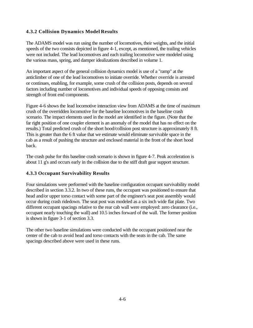
The risk function selected for assessment of possible head injury is depicted in figure 3-2. It relates the magnitude of the HIC to the probability of sustaining a minimum AIS �2 level (moderate) injury, i.e., the occurrence of linear skull fracture and/or a state of
unconsciousness lasting less than one hour. Examination of this curve indicates that 90% of
the general population would not be expected to sustain such injury (i.e., only 10% would be
expected to incur AIS�2 trauma) if the HIC did not exceed 262. In the context of the
tolerance limit defined in table 3-1, a 1000 HIC is associated with a 43% probability that the
general population would be likely to suffer casualties of this nature.
Figure 3-3 shows the risk function selected for evaluation of possible chest injury. It relates
the magnitude of CR to the probability of sustaining a minimum AIS�3 level (severe) general thoracic trauma, i.e., the occurrence of various rib fracture mechanisms with or without hemothorax or pneumothorax. This curve indicates that 90% of the general population would
not be expected to be injured in this manner (i.e., only 10% would be expected to suffer such
trauma) if the CR remained below 8 g's. Inspection of this profile shows that there is a 57%
probability that the general population would be likely to incur this type of injury if subjected
to the 60 g CR tolerance limit noted in table 3-1.
3-5

Probability curves are available for other injury, or AIS, levels. However, we chose the AIS > 2 level for HIC and AIS > 3 for CR because they seemed to best correspond to the onset of "serious" injury.
3-6

4. BASELINE CRASH SCENARIO
4.1 OVERVIEW
The baseline crash scenario is a simulated collision used to test the feasibility of an individual crashworthiness design concept to improve occupant survivability over that provided by a
locomotive just satisfying S-580. The approach, as discussed in section 3, is to perform the
simulation in one case with the lead locomotives just satisfying S-580 and having the design
concept, and in the other case with the lead locomotives just satisfying S-580. The scenario
was derived from an actual head-on collision accident for which there was severe cab crush
and a fatality; we felt that the head-on collision represents the worst case challenge to the cab
of a locomotive. Selection of a collision that experienced such damage provides an
opportunity to demonstrate improvement.
4.2 DESCRIPTION
A description of the accident on which the baseline crash scenario is based is depicted in
figure 4-1. It consisted of two trains, one with two locomotives and 15 trailing vehicles
traveling at a speed of 9 mph, and one with five locomotives and 92 trailing vehicles
traveling at a speed of 21 mph. This gives a closing speed of 30 mph. In the actual head-on
collision the lead locomotive of the 21 mph train was overridden by the lead locomotive of
the 9 mph train resulting in one fatality in the overridden locomotive due to about 10 ft of
cab crush. Although the lead locomotive did not strictly satisfy S-580 - its anticlimber at the short hood end did not extend across the entire width of the locomotive - our
calculations suggest that the resulting crush would have been comparable had the lead, overridden locomotive satisfied S-580. This is primarily due to our assessment that the
anticlimber as specified by S-580 is apparently not effective in preventing override [1]. Figure 4-2 is a photograph of the lead locomotives in the accident.
The baseline crash scenario is very similar to the description provided in figure 4-1. The primary difference is that trailing vehicles are not simulated; this was found to be
a reasonable approximation in determining the damage to the lead locomotives [1]. Otherwise, the locomotive weights shown in figure 4-1 were included in the analysis.
4.3 MODEL APPLICATION
4.3.1 Structural Damage Model Results
Development of the load-crush curves for the locomotive that just satisfies S-580, which we
will refer to here as the baseline locomotive, is described in volume 1. However, for
comparison to concept curves to be presented below, figures 4-3 through 4-5 show the
load-crush curves for the draft gear support structure, anticlimber, and short hood/collision
post structure due only to longitudinal loading for the simulated baseline locomotive. Note
that the peak load for the short hood/collision post structure is determined by a buckling
phenomenon involving the short hood, and not the basic required strength of the collision
posts.
4-1

4-2

4-3

4-4

4-5
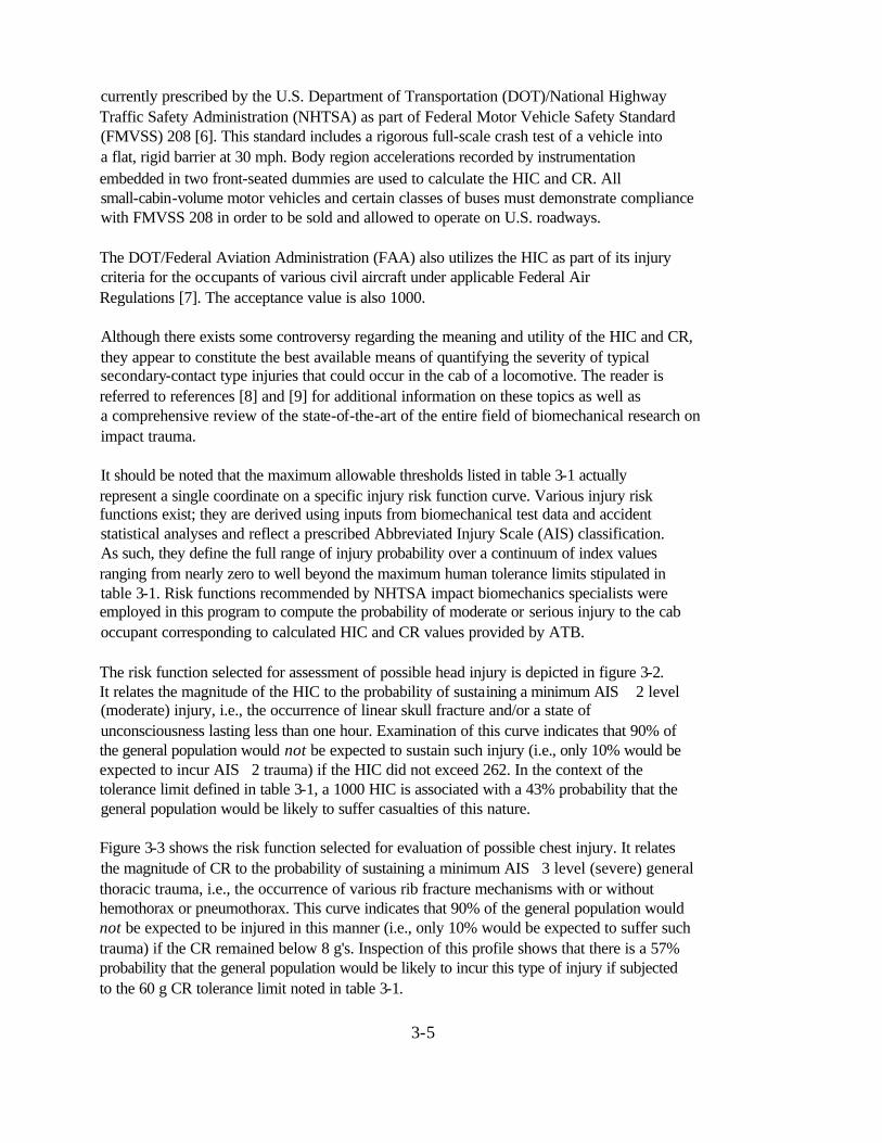
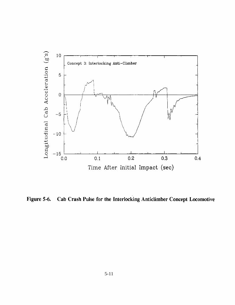
4.3.2 Collision Dynamics Model Results The ADAMS model was run using the number of locomotives, their weights, and the initial speeds of the two consists depicted in figure 4-1, except, as mentioned, the trailing vehicles were not included. The lead locomotives and each trailing locomotive were modeled using the various mass, spring, and damper idealizations described in volume 1. An important aspect of the general collision dynamics model is use of a "ramp" at the anticlimber of one of the lead locomotives to initiate override. Whether override is arrested or continues, enabling, for example, some crush of the collision posts, depends on several factors including number of locomotives and individual speeds of opposing consists and strength of front end components. Figure 4-6 shows the lead locomotive interaction view from ADAMS at the time of maximum crush of the overridden locomotive for the baseline locomotives in the baseline crash scenario. The impact elements used in the model are identified in the figure. (Note that the far right position of one coupler element is an anomaly of the model that has no effect on the results.) Total predicted crush of the short hood/collision post structure is approximately 8 ft. This is greater than the 6 ft value that we estimate would eliminate survivable space in the cab as a result of pushing the structure and enclosed material in the front of the short hood back. The crash pulse for this baseline crash scenario is shown in figure 4-7. Peak acceleration is about 11 g's and occurs early in the collision due to the stiff draft gear support structure. 4.3.3 Occupant Survivability Results Four simulations were performed with the baseline configuration occupant survivability model described in section 3.3.2. In two of these runs, the occupant was positioned to ensure that head and/or upper torso contact with some part of the engineer's seat post assembly would occur during crash ridedown. The seat post was modeled as a six inch wide flat plate. Two different occupant spacings relative to the rear cab wall were employed: zero clearance (i.e., occupant nearly touching the wall) and 10.5 inches forward of the wall. The former position is shown in figure 3-1 of section 3.3. The other two baseline simulations were conducted with the occupant positioned near the center of the cab to avoid head and torso contacts with the seats in the cab. The same spacings described above were used in these runs.
4-6

4-7

ATB predictions for the baseline configuration in the baseline crash scenario are summarized in table 4-1. The HIC ranged between 11 and 260, with an average value of 159. Examination of figure 3-2 indicates that the latter level of HIC would produce moderate head injury for less than 5% of the simulated occupants.
Table 4-1. Locomotive Cab Occupant Response to the Baseline Crash Scenario
Head Response Torso Response Occupant Position in Cab
HIC CR (g's)
Behind engineer's seat, against rear wall 260 16
Behind engineer's seat, forward of rear wall 11 18
Center of cab, against rear wall 166 18
Center of cab, forward of rear wall 197 27
The three-millisecond clipped maximum resultant chest acceleration (CR) averaged 20 g's over a range of 16 to 27 g's. According to figure 3-3, this average level of acceleration is associated with serious thoracic trauma for about 27% of the simulated occupants. HIC and CR values were directly influenced by the location, nature, and timing of multiple body region contacts with cab interior surfaces. The four simulations indicated that a variety of direct and indirect impacts (i.e., contact cushioned by an arm) could occur. Head contacts were made with the floor, engineer's seat support, and front cab wall. Torso contacts were made with the floor, underside and exterior (unpadded) back surface of the engineer's seat, and front cab wall. The occupant survivability measures calculated for this baseline case, while demonstrating some probability of severe injury, generally suggest the crew remaining in the cab in this collision could have survived had override and substantial crush not occurred.
4-8

5. CRASHWORTHINESS CONCEPTS
5.1 OVERVIEW This section provides a description of the various concepts investigated to address the crashworthiness features identified in Public Law 102-365. For each concept, a brief review is given of the manner in which the feature is currently addressed both in S-580 and in recently manufactured locomotives. This is followed by a description for each concept, including a sketch and a discussion of the geometry, material, and fabrication method assumed, and estimates of cost and weight. Next, the evaluation results are presented, including: the load-crush curves generated and used in the collision dynamics analyses; the total crush and crash pulse obtained from the collision dynamics model; and the calculated occupant survivability measures. Discussion on the overall implications of the evaluation to our conclusions on which Public Law crashworthiness features are most likely to yield practical benefit is provided in volume 3 of this report series. 5.2 COLLISION POSTS 5.2.1 Current Practice The S-580 specification requires that collision posts have an ultimate strength of 500,000 lbf each for a longitudinal load applied at the deck level and an ultimate strength of 200,000 lbf each for a longitudinal load applied 30 inches above the deck. Current freight locomotives in the U.S. achieve these strengths by utilizing a solid plate element welded to the underframe in some manner. The plate material is an alloy steel ranging in yield strength from 50 to 100 ksi. Our calculations suggest that the ultimate load carrying capacity of currently employed posts exceeds the S-580 requirement by more than a factor of two. For example, Canadian National requires that each post sustain a longitudinal load of at least 500,000 lbf at 30 inches above the deck. This is achieved by using high strength material with conventional geometry. Our estimate of the weight of a currently used post ranges from 600 to 900 lb depending on manufacturer and model. 5.2.2 Concept Description Various forms of collision posts were considered in our concept generation meetings. They included posts of similar geometry made of higher strength materials, posts of similar materials with cross sections providing larger plastic bending strengths, and multiple posts to even out the load crush curve and provide a deliberate ramping action for a potentially overriding locomotive.
5-1

The collision post geometry selected for analysis in this project is illustrated in figure 5-1. It is tapered in the vertical direction with a cross section that resembles a structural wide flange beam. It appears feasible to fix it in the same location as current posts; it would also be welded to the short hood structure. This geometry was found to provide a good balance between minimum weight and maximum load carrying capacity. The tapered geometry takes advantage of the need for greater bending resistance at the base than at the point of load application. The same 50 ksi yield strength material used for the baseline case was used here. The post was designed to provide the same weight as the collision post analyzed for the baseline scenario; that is, there was no increase in weight. Details for the method of welding such a post to the underframe were not investigated. However, one possibility is to weld the proposed post web directly over the web of the primary underframe beams and to carry the post flanges through the deck for welding along the web of the underframe beam webs. A somewhat deeper beam section at the deck would probably be required to provide the necessary shear strength. Quotes obtained from vendors for the welded collision post structural shapes suggest a price of about $500/post. Our estimate of the differential cost over current designs, including welding to the underframe is about $1000 for both posts. As a note, there is a strength limit for the collision posts beyond which bending of the underframe rather than the posts will occur; this limit is about 1 to 1.5 million pounds per post at 30 inches above the deck. 5.2.3 Evaluation Results The load-crush curve for two concept collision posts acting together is shown in figure 5-2, indicating that the ultimate strength is 800,000 lbf per post for a load applied 30 inches above the deck. This value is four times the value specified in S-580. Recalling also that such a strength (500,000 lbf) is currently in practice by utilizing high strength material with conventional geometries indicates that substantially higher collision post strengths are achievable by a variety of approaches. The collision dynamics model results indicate that cab crush is substantially reduced when the concept collision post replaces the post that just satisfies S-580 in the baseline crash scenario. The predicted short hood/collision post crush for this concept is only 1 ft compared to the baseline value of 8 ft. Peak acceleration in the simulated collision with the stronger collision posts is the same as for the case that just satisfies S-580, since the peak occurs during failure of the draft gear support structure and before engagement of the collision posts. Note that the pulse shown in figure 5-3 differs from the baseline crash pulse (figure 4-7) at later times in the collision, when the posts are engaged. Four ATB simulations were conducted using the baseline configuration occupant survivability model described in section 3.3.2. Occupant positions in the cab were identical to those employed with the baseline crash scenario discussed in section 4.1.
5-2

5-3

5-4

ATB predictions for the collision post design concept crash pulse are shown in table 5-1. The HIC exhibited a wide range of values from a low of 55 to a high of 725; the average magnitude was 332 compared to 160 in the baseline. The injury risk function shown in figure 3-2 indicates that approximately 12% of the simulated occupants would be likely to suffer a minimum level AIS�2 head trauma for this average exposure.
Table 5-1. Locomotive Cab Occupant Response for the Collision Post Concept
Head Response Torso Response Occupant Position in Cab
HIC CR (g's)
Behind engineer's seat, 725 36 against rear wall
Behind engineer's seat, 55 27 forward of rear wall
Center of cab, 157 39 against rear wall
Center of cab, 390 44 forward of rear wall
The three-millisecond clipped maximum resultant chest acceleration (CR) displayed a relatively narrow variance: 27 to 44 g's. Average CR was 37 g's (compared to 20 in the baseline); this magnitude of acceleration would, according to figure 3-3, subject about 43% of the simulated occupants to the chance of sustaining a minimum level AIS�3 general thoracic trauma. As was the case with simulations conducted with the baseline locomotive crash pulse, the above two injury parameters were highly dependent on secondary impact considerations. Key head impacts occurred with the floor, support, underside, and exterior (unpadded) back surface of the engineer's seat; and with the front wall. The severity of some of these contacts were mitigated by the cushioning presence of an arm between the head and a cab interior surface. The torso contacted the floor and front wall of the cab. 5.3 ANTICLIMBERS/UNIFORM SILL HEIGHTS 5.3.1 Current Practice Anticlimbers on locomotives that satisfy S-580 are required to sustain a vertical load of 200,000 lbf applied under the anticlimber, uniformly distributed between the center sill webs. The specification also requires that the anticlimber shall be attached to the underframe end plate in line with the center sill webs. No indication is given for the longitudinal location under the anticlimber at which the load is to be applied, although manufacturers use the very front, which is the conservative position. There is also no requirement on the longitudinal strength of the anticlimber.
5-5

The 200,000 lbf strength is achieved by using one or more plates angled down from the horizontal surface, or top plate, of the anticlimber to the underframe front plate; figure 5-4 shows the geometry analyzed for the baseline case. Our analysis suggests that anticlimbers on locomotives built after S-580 was implemented achieve a vertical strength more than 50% greater than that required. The technical basis for the anticlimber vertical strength required by S-580 has, to our knowledge, not been published. Discussions with locomotive and railroad personnel suggest that the anticlimber was originally conceived to protect against debris rising toward the cab from grade crossing collisions. We also understand that some feel a strength greater than 200,000 lbf is not needed, since greater loads would lift the end of the locomotive. Uniform sill heights are not currently specified by S-580 or any other U.S. standard. The need for uniform sill heights to prevent override and ensure the interaction of the underframes in collisions has been cited by the NTSB [10]. Our review of head-on collision accident reports [1], including one in which the sill heights differed by less than one inch, indicates that uniform sill height with current front end arrangements will not prevent override. This is probably due to the occurrence of asymmetric shear deformations between interacting anticlimbers during a collision, which can permit one anticlimber to ramp over another. An important result of our work reported in volume 1 is that the anticlimber will, in general, not experience a significant vertical load in a head-on collision and that, consequently, it provides little or no protection against override. Photographs of actual head-on collisions as well as model results indicate that deformation of the anticlimber and the draft gear support structure occurs primarily in shear. In addition, the time or force required to have the coupler of one locomotive vertically challenge the anticlimber of the other locomotive in a head-on collision appears too excessive to be physically possible in all but the slowest collisions. Even if the coupler, or another component, did vertically challenge the anticlimber in a collision, the force required to lift the end of a locomotive would be much larger than one-half the locomotive body weight, because of rotational inertia effects. For these reasons we sought anticlimber concepts that provided a more direct interaction in a head-on collision than that apparently afforded by current designs.
5-6

5-7

5.3.2 Concept Description The interlocking anticlimber concept selected for evaluation also addresses the crashworthiness feature of uniform sill heights, because sill height influences anticlimber effectiveness. Comparable anticlimbers would need to be installed on all locomotives for this concept to be effective, which is clearly a disadvantage. The anticlimber analyzed here has the geometry depicted in figure 5-5. It is a cast ductile iron piece welded to the underframe front plate that consists of integral, protruding shelves such that two opposing interlocking anticlimbers would fit together and provide substantial resistance to relative vertical motion. The concept interlocking anticlimber is intended to project out beyond the front plate enough to provide protection against rising debris from grade crossing collisions and to have a small but positive engagement when two opposing locomotives are in a full buff position. This engagement in the buff position would cause no longitudinal load between anticlimbers. Although not considered in detail here, the anticlimber would require additional design to account for the effects of vertical height differences and coupling in curves. There will always be some difference in vertical height between locomotives, even with uniform sill heights, as a result of manufacturing tolerances, wheel wear, and dynamic motion prior to collision. If sill heights were uniform this difference could amount to four to five inches and a comparable vertical tolerance in the shelves of the interlocking anticlimber would be required. In the absence of uniform sill heights a tolerance of 10-12 inches would probably be required. Finally, in order to prevent contact between anticlimbers for coupled locomotives in curves, the anticlimber width would have to be narrower than the full locomotive width. The concept, as investigated here, has been idealized by assuming no vertical offset between the sill neutral axes of the colliding locomotives, so that underframe energy absorption is maximized. The effect of vertical offset is investigated in volume 4 of this report. Tough, castable materials are available with the strength and toughness needed for this design to resist over 1,000,000 lbf vertically without fracturing on impact. The increase in weight resulting from use of this interlocking anticlimber over current designs is about 2000 lb. A quote from a vendor for a cast piece with the approximate geometry shown in figure 5-5 is about $5000. 5.3.3 Evaluation Structural deformation analyses were not conducted for the interlocking anticlimber. Rather, the cast piece was assumed to have compressive strength sufficient to transfer all of the longitudinal collision load to the underframe, whose load-crush curve has been generated and reported in volume 1.
5-8

5-9

The collision dynamics model was run by assuming that once the two colliding locomotives interlock, there would be no relative vertical displacement between them at the anticlimbers. Relative rotation was allowed. As a result there was no loading of the short hood/collision posts structure and, therefore, no crush. On the other hand, there was a small increase in the peak acceleration but a large increase in its duration, as expected and as shown in the crash pulse of figure 5-6. A maximum acceleration of about 12 g's acting over a ~150 msec period is predicted for this collision vs. the 11 g value over a ~60 msec period for the locomotive that just satisfies S-580, both in the baseline crash scenario. The occupant survivability model was again exercised with occupant positions identical to those used for the baseline crash scenario. Table 5-2 presents the occupant performance predictions generated by ATB. The HIC parameter displayed disparate values between 56 and 1830, with an average of 925 (compared to 160 in the baseline). This magnitude would be likely to cause about 43% of the simulated occupants to incur moderate head trauma of the nature described in section 3.4.
Table 5-2. Locomotive Cab Occupant Response for the Interlocking Anticlimber
Head Response Torso Response Occupant Position in Cab
HIC CR (g's)
Behind engineer's seat, 809 45 against rear wall
Behind engineer's seat, 56 17 forward of rear wall
Center of cab, 1830 73 against rear wall
Center of cab, 1005 66 forward of rear wall
Occupant chest response also varied significantly, ranging from 17 to 73 g's. Average CR was 50 g's (compared to 20 in the baseline), indicating that about 53% of the simulated occupants would be exposed to severe thoracic trauma. The varied nature of the secondary contacts in the cab again played a major role in generating the injury-indicating parameters listed in table 5-2. Both direct and indirect head contacts occurred with the front wall as well as with the support, underside, and exterior back surface of the engineer's seat. The torso impacted the floor, the front wall, and the seat support (indirect via arm).
5-10
5-11
5.4 CRASH REFUGES
5.4.1 Current Practice
The crash refuge feature refers generally to an area or volume into which crew members can position themselves to be protected from secondary impact, crush, or both. Currently, there are no U.S. standards requiring a crash refuge for a rail vehicle. This topic was the subject of some prior work on freight locomotive crashworthiness [2], which recommended that the cab consist of a strong structural "cage" that could also act as a ramp to vertically deflect an overriding locomotive or other vehicle. Some high speed rail vehicles are now designed with what one could consider a crash refuge [11]. In this case, a length of the car is reinforced to have greater longitudinal crush strength than the parts of the vehicle on either side of it. In the event of a collision with substantial crush, the zones on each side of this protected length would crush sacrificially. In conducting interviews with railroad personnel it became very evident that there would be great resistance to a refuge that would be totally enclosed. This perception affected our choice of concepts. 5.4.2 Concept Descriptions
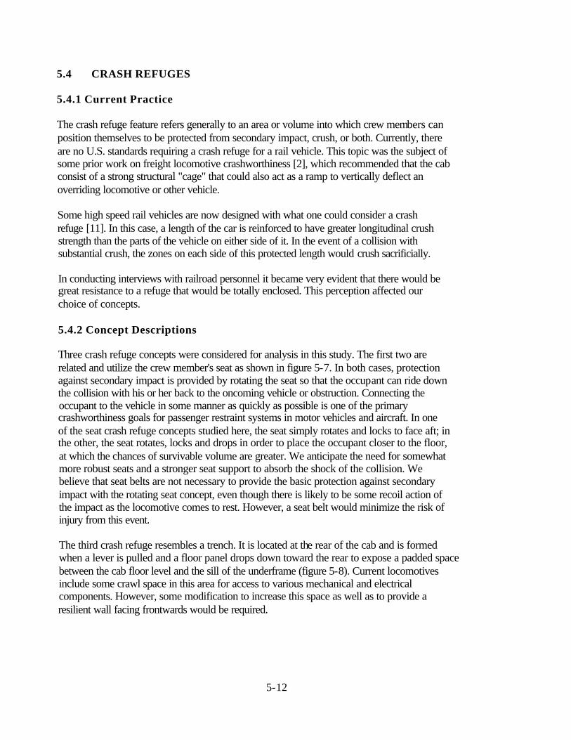
Three crash refuge concepts were considered for analysis in this study. The first two are related and utilize the crew member's seat as shown in figure 5-7. In both cases, protection against secondary impact is provided by rotating the seat so that the occupant can ride down the collision with his or her back to the oncoming vehicle or obstruction. Connecting the occupant to the vehicle in some manner as quickly as possible is one of the primary crashworthiness goals for passenger restraint systems in motor vehicles and aircraft. In one of the seat crash refuge concepts studied here, the seat simply rotates and locks to face aft; in the other, the seat rotates, locks and drops in order to place the occupant closer to the floor, at which the chances of survivable volume are greater. We anticipate the need for somewhat more robust seats and a stronger seat support to absorb the shock of the collision. We believe that seat belts are not necessary to provide the basic protection against secondary impact with the rotating seat concept, even though there is likely to be some recoil action of the impact as the locomotive comes to rest. However, a seat belt would minimize the risk of injury from this event. The third crash refuge resembles a trench. It is located at the rear of the cab and is formed when a lever is pulled and a floor panel drops down toward the rear to expose a padded space between the cab floor level and the sill of the underframe (figure 5-8). Current locomotives include some crawl space in this area for access to various mechanical and electrical components. However, some modification to increase this space as well as to provide a resilient wall facing frontwards would be required.
5-12

5-13

5-14

All three of these crash refuge concepts protect the occupant against secondary impact but provide limited or no protection against crush. Thus, some other feature would be required to protect the crew in the baseline crash scenario, for which a crush of 8 ft is predicted. Estimates of weight and cost increases associated with these three concepts are listed in table 5-3.
Table 5-3. Estimates of Weight and Cost Increase Over the Baseline Locomotive for the Three Crash Refuge Concepts Analyzed in this Study
Crash Refuge Concept Measure
Rotate Seat Only Rotate & Drop Seat Trench
Weight 300 600 400
Cost increase $15,000 $20,000 $2,000
5.4.3 Evaluation In making the evaluations of the crash refuge concepts we recall that any of these refuges alone would not protect the occupant against the crush of the baseline crash scenario, since they add no strength or crush resistance to the front end components. Therefore, the evaluation is made to determine what, if any, reduction in secondary impact measures is provided by the crash refuge concept. If there is reduction, then the concept could be of practical use when combined with other crashworthiness features that induce more severe crash pulses, such as the interlocking anticlimber. Finite element analyses and collision dynamics calculations were not needed to evaluate these concepts. Instead, approximate, hand calculations were made to estimate the strength required for rotating seat support posts, and support channels for the trench concept. The crash pulse generated for the baseline crash scenario was also used for each refuge concept. ATB model VIEW-generated drawings of the occupant in each crash refuge configuration are shown in figures 5-9, 5-10, and 5-11, respectively.
5-15

5-16

5-17

The rotating seat models utilized seat geometry and cushioning (i.e., force-deflection and energy absorbing) material properties indicative of seat characteristics found on a late model domestic light truck. Padding characteristics used in the trench refuge model were given a stiffness roughly midway between that specified for the seat cushioning material and cab floorpan. ATB-predicted occupant response for the crash refuge concepts are presented in table 5-4. Minimum-level HICs were recorded for all three concepts, indicating that most of the simulated occupants would not be exposed to even moderate head trauma. Chest accelerations ranged between 15 and 28 g's; these levels correspond to about a 20 to 36% chance of incurring severe general thoracic trauma.
Table 5-4. Locomotive Cab Occupant Response for the Crash Refuge Concepts (Baseline Crash Pulse)
Torso Occupant Head Response Response Remarks
Position in Cab HIC CR (g's)
Engineer's seat 95 28 Occupant slid on the seat location (rotate only) (towards the rear of the cab)
during the latter stages of the crash ridedown
Engineer's seat 62 21 Occupant slid on the seat location (rotate and (towards the rear of the cab) drop) during the latter stages of the
crash ridedown
In trench located at 165 15 the rear of the cab
The seat-type crash refuge simulations shared one extremely important commonality: no body region contacts occurred with cab interior surfaces other than the floor (feet only) and the padded seat cushion and seat back components. In the trench crash refuge simulation, the occupant stayed within the confines of the protective trench during the collision ridedown period. The trench was assumed to be deep enough to prevent whiplash-type loading. The absence of uncontrolled kinematics and inevitable, potentially damaging secondary impacts with hard cab interior surfaces constitutes a most noteworthy occupant performance result. ATB calculations were also conducted to assess the benefit provided by the crash refuges for the more serious crash pulse provided by the interlocking anticlimber. Table 5-5 lists the values obtained for two of the crash refuge concepts.
5-18

Table 5-5. Locomotive Cab Occupant Response for the Crash Refuge Concepts (Interlocking Anticlimber Crash Pulse)
Head Response Torso Response Occupant
HIC CR (g's)
Engineer's seat location (rotate only) 247 30
In trench located at the rear of the cab 404 55
The HIC values are higher than the baseline - 106 - still relatively low. The value of CR is low for the seat refuge and relatively high for the trench; compare to CR = 20 for the baseline. 5.5 ROLLOVER PROTECTION DEVICES 5.5.1 Current Practice There appear to be no current industry or federal specifications for rollover protection in freight locomotives. Apparently, locomotive manufacturers and operators also do not provide explicit structure to protect against rollover. Some industry personnel with whom we spoke suggest that existing hardware, such as engine components and the electrical cabinet located at the rear of the cab, could provide some protection in the event of rollover. However, all admitted that such protection has not been tested in published accidents. 5.5.2 Concept Description Figure 5-12 illustrates the roll bar concept generated and analyzed in this project. It is essentially a structural frame located near the front of the cab attached to the underframe at each side of its base. The structural member sizes that we estimate would be required to support rollover loads are large enough to require some redesign of the front cab; otherwise, there would be some obstruction of vision. We also investigated having another frame located at the rear of the cab but decided against this option in light of the added weight and the likelihood that the equipment in the long hood would provide some support during a rollover. The estimated cost and weight associated with the front cab roll bar are: $10,000 and 3,000 lb, respectively.
5-19
5-20

5.5.3 Evaluation The formulation of our concepts was guided primarily by selecting a loading felt to provide some equivalence to that which would occur in a rollover. This loading is depicted in figure 5-13. Top loading is derived from the federal standard for school buses [12], which requires that the roof not compress by more than 5 inches when subjected to a vertical load equal to 1.5 times the bus's empty weight applied over a prescribed area of the roof. The roof load used for the locomotive roll bar strength analysis was taken as one-half the locomotive weight. This represents our belief that one-half of the locomotive weight will be supported by some other part of the body. Side loading was also investigated in selecting roll bar section size and, in fact, was the determining load. In this case, the roll bar was required to also sustain one-half the locomotive weight at the roof line. This load was arrived at from a few considerations. First, it is the static load that would have to be supported if one-half the load was supported by the underframe and the other half was totally supported by the roll bar. We can also arrive at this value by assuming four load support points - one being the roll bar - but applying a dynamic amplification factor of two. Finally, the recent specification for high speed trainsets made a similar requirement for the vehicles. The resulting square tube sections required to support the side loads of figure 5-13 are 14 inches x 14 inches x 1/2 inch and weigh 90 lb/ft. For comparison, our analysis of a structure that approximately represents that found in currently manufactured locomotive cabs indicates that the ultimate side load, at the roof line, in less than 20,000 lbf. Occupant survivability analyses were not conducted for this case, since a crash scenario was not uncovered or selected for its evaluation. Rather, the benefit provided to the crew can only be judged by the calculations that suggest that survivable space will be maintained in the event of a rollover. 5.6 DEFLECTION PLATES 5.6.1 Current Practice Again, there are apparently no industry or federal requirements related to deflection plates. The idea behind this type of feature, we believe, is to deflect another train or road vehicle laterally from the path of the lead locomotive to minimize damage to the cab. This feature raised much discussion among the team and industry personnel, particularly with respect to the issue of whether it is desirable to derail one or both trains during a train-to-train collision. Although this seems an important issue, we did not address it in investigating concepts for this feature.
5-21

5-22
5.6.2 Concept Description The deflection plate concept we analyzed was very similar to the interlocking anticlimber concept discussed in section 5.2. It is intended to act as an anticlimber, to include the interlocking lips and to form a point in plan view as shown in figure 5-14. The surfaces forming the point were selected to have a 12.5-degree angle with respect to the usual front plate, because this was felt to be the largest possible angle without substantially extending the length of the locomotive underframe. The estimated cost and weight for this concept is $5,000 and 2,000 lb, respectively. 5.6.3 Evaluation The collision dynamics model was first modified to treat lateral motion of the vehicles in the consist. A lateral ramp, rather than a vertical one, was placed on the lead locomotive of the 21 mph consist. In addition, coupler interaction between the lead locomotives was not included and motion was only permitted in a plane parallel to the ground; in other words, there was no pitch. The load-crush response of the deflection plate/underframe was taken to be the same as was used for the underframe alone in the evaluation of the interlocking anticlimber crashworthiness concept. Calculations were first conducted to determine whether the 12.5-degree deflection plates would cause lateral deflection. Only the two lead locomotives of the baseline consists were modeled and no resistance to lateral motion was included. The results showed that the collision was nearly identical to that of the interlocking anticlimber: no significant lateral deflection occurred prior to arrest. In fact, the deflection angle had to be increased to nearly 45 degrees before substantial lateral deflection of the type envisioned occurred. Figure 5-15 is a plot of longitudinal load vs. lateral deflection for the 45-degree case, showing that a collision force of nearly 6x10⁶ lbf resulted prior to substantial lateral deflection. These calculations strongly suggest that very large deflection plate angles, and consequently, a large increase in underframe length, would be required to overcome the lateral resistance that exists in track and to significantly deflect the train before inducing excessive crush of the lead locomotives. For this reason, no further calculations were conducted.
5-23

5-24

5-25

5.7 SHATTERPROOF WINDOWS 5.7.1 Current Practice The current Code of Federal Regulations [13] states the following requirements imposed by the FRA for window glazing in locomotive cabs: • all locomotives built after June 30, 1980 must be equipped - and all locomotives built
before this date must be retrofitted - with certified glazing in all cab windows,
• glazed windows must be able to deflect, with no penetration, 24 lb cinder blocks (8 inches x 8 inches x 16 inches) at 44 ft/sec (30 mph),
• glazed windows must be able to sustain, with no penetration, a 0.22 caliber bullet at 960 ft/sec.
Penetration is determined in these tests by whether penetration occurs in a 0.006-inch thick foil witness plate six inches behind the glazing. It is not clear how and with what margin these requirements are being met by the locomotive manufacturers. 5.7.2 Concept Description There are a number of glazing systems commercially available that can meet the Code of Federal Regulations requirements. Table 5-6 lists four glazing options with increasing resistance to shatter and penetration as demonstrated by impact of a steel, two-inch-diameter cylindrical dart with a hemispherical tip at 30 mph (44 ft/sec) [14]. The options are listed in order of increasing effectiveness and cost. The first glazing type, which apparently just meets the FRA requirements, consists of layers of tempered glass between which is laminated a relatively thick layer of polyvinyl butyral (PVB). The second system includes a spall shield on the interior surface and raises the level of protection modestly. On the other hand, glazing that utilizes polycarbonate (PC) in place of the PVB interlayers demonstrates substantial improvement over the first system with about a 50% increase in cost. Even greater improvements can be had for additional cost as shown in the table. Our design concept of choice for shatterproof windows is the system with tempered glass and PC interlayers because it appears to offer the best performance improvement for the cost. We have also assumed that some modification of the window frames would be required in order to take advantage of the increase in window strength. Thus, our estimate of the increase in cost for the shatterproof window concept is about $1000 for the locomotive with no significant increase in weight.
5-26
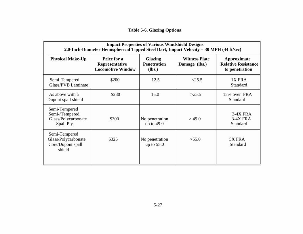
Table 5-6. Glazing Options
Impact Properties of Various Windshield Designs 2.0-Inch-Diameter Hemispherical Tipped Steel Dart, Impact Velocity = 30 MPH (44 ft/sec)
Physical Make-Up Price for a Glazing Witness Plate Approximate Representative Penetration Damage (lbs.) Relative Resistance
Locomotive Window (lbs.) to penetration
Semi-Tempered $200 12.5 <25.5 1X FRA Glass/PVB Laminate Standard
As above with a $280 15.0 >25.5 15% over FRA Dupont spall shield Standard
Semi-Tempered Semi-/Tempered 3-4X FRA
Glass/Polycarbonate $300 No penetration > 49.0 3-4X FRA Spall Ply up to 49.0 Standard
Semi-Tempered
Glass/Polycarbonate $325 No penetration >55.0 5X FRA Core/Dupont spall up to 55.0 Standard
shield
5-27

5.7.3 Evaluation As with the roll bar crashworthiness concept, it is difficult to evaluate the improvement afforded the crew as a result of implementing the window concept, because evaluation of accident statistics, particularly related to injury from window breakage and penetration, was not part of our study. However, we note that improved penetration resistance also provides benefit with respect to deterring post-collision entry of flammable liquids. 5.8 EQUIPMENT TO DETER POST-COLLISION ENTRY OF FLAMMABLE
LIQUIDS
5.8.1 Current Practice Current federal standards do not provide explicit requirements for equipment to deter post-collision entry of flammable liquids. However, there are some current standards and industry practices that do, we believe, provide some protection. For example, the short hood requirement in S-580 of a 0.5-inch wall thickness, 25 ksi yield strength product provides protection against penetration. We estimate, using information from reference [15], that this effectively protects against penetration of a 1-inch-diameter, 1-foot-long steel rod impacting head-on directly onto the short hood at a speed of 60 mph. At least one manufacturer, and perhaps others, include covers over the openings for lights in the short hood explicitly to prevent penetration. Finally, the door in the front of the short hood opens outward, ensuring that it will not accidentally open inward. The penetration resistance of the glazing can also be considered to provide protection against ingress of materials in a collision, provided they remain intact and in their frames. 5.8.2 Concept Description No specific concepts other than those currently being used by industry were felt to deserve detailed assessment in this study. An exception to this is the use of windows with greater penetration resistance, as described in the previous section. The team felt that the penetration resistance provided by the short hood specification in S-580 was sufficient and that the practice of covering openings should continue. One idea raised for the door was the use of some type of gasket to prevent the ingress of fluids in an accident; we are not certain whether this concept is currently being used.
5-28

6. SUMMARY
This report describes the design concepts generated and evaluated to address each of the crashworthiness features described in Public Law 102-365. One concept was selected for analysis for each of the eight features, except the crash refuge, for which three concepts were analyzed. The concepts were selected to establish feasibility of providing practical and cost-effective improvement in cab crashworthiness. It is our expectation that should improvement in any given feature be pursued, there are likely more practical and efficient designs. Table 6-1 lists the concepts evaluated, together with the key results. These results will be used to make a prioritization of the concepts most likely to practically benefit the locomotive crew and operating companies and will be reported in volume 3 of this report series.
6-1
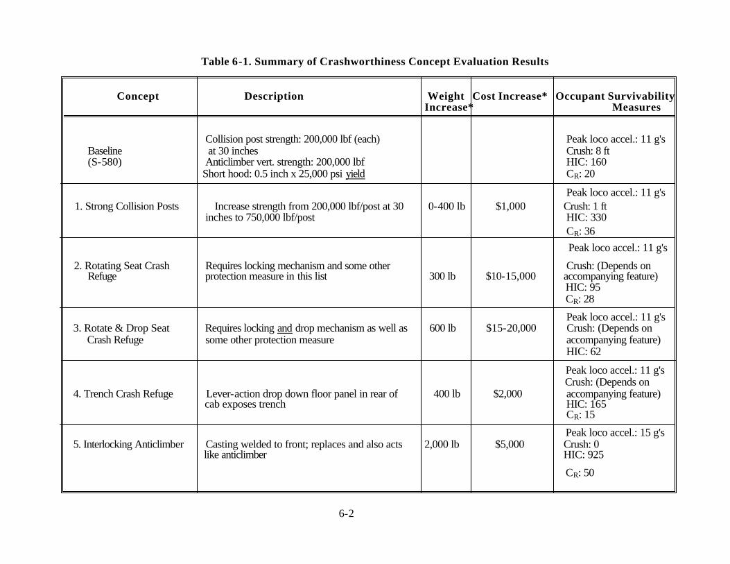
Table 6-1. Summary of Crashworthiness Concept Evaluation Results
Concept Description Weight Cost Increase* Occupant Survivability Increase* Measures
Collision post strength: 200,000 lbf (each) Peak loco accel.: 11 g's Baseline at 30 inches Crush: 8 ft (S-580) Anticlimber vert. strength: 200,000 lbf HIC: 160
Short hood: 0.5 inch x 25,000 psi yield CR: 20
Peak loco accel.: 11 g's 1. Strong Collision Posts Increase strength from 200,000 lbf/post at 30 0-400 lb $1,000 Crush: 1 ft
inches to 750,000 lbf/post HIC: 330 CR: 36
Peak loco accel.: 11 g's
2. Rotating Seat Crash Requires locking mechanism and some other Crush: (Depends on Refuge protection measure in this list 300 lb $10-15,000 accompanying feature)
HIC: 95 CR: 28
Peak loco accel.: 11 g's 3. Rotate & Drop Seat Requires locking and drop mechanism as well as 600 lb $15-20,000 Crush: (Depends on
Crash Refuge some other protection measure accompanying feature) HIC: 62
Peak loco accel.: 11 g's Crush: (Depends on
4. Trench Crash Refuge Lever-action drop down floor panel in rear of 400 lb $2,000 accompanying feature) cab exposes trench HIC: 165 CR: 15
Peak loco accel.: 15 g's 5. Interlocking Anticlimber Casting welded to front; replaces and also acts 2,000 lb $5,000 Crush: 0
like anticlimber HIC: 925
CR: 50
6-2
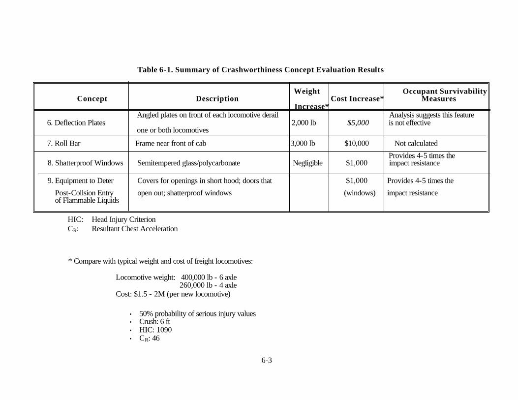
Table 6-1. Summary of Crashworthiness Concept Evaluation Results
Weight Occupant Survivability Concept Description Cost Increase* Measures
Increase* Angled plates on front of each locomotive derail Analysis suggests this feature
6. Deflection Plates 2,000 lb $5,000 is not effective one or both locomotives
7. Roll Bar Frame near front of cab 3,000 lb $10,000 Not calculated
Provides 4-5 times the 8. Shatterproof Windows Semitempered glass/polycarbonate Negligible $1,000 impact resistance
9. Equipment to Deter Covers for openings in short hood; doors that $1,000 Provides 4-5 times the
Post-Collsion Entry open out; shatterproof windows (windows) impact resistance of Flammable Liquids
HIC: Head Injury Criterion
CR: Resultant Chest Acceleration
* Compare with typical weight and cost of freight locomotives:
Locomotive weight: 400,000 lb - 6 axle 260,000 lb - 4 axle
Cost: $1.5 - 2M (per new locomotive)
• 50% probability of serious injury values • Crush: 6 ft • HIC: 1090
• CR: 46
6-3

REFERENCES
1. Mayville, R. A., R. G. Stringfellow, R. J. Rancatore, and T. P. Hosmer. 1995. Locomotive Crashworthiness Research, Volume 1: Model Development and Validation. Report to U.S. Department of Transportation, Volpe National Transportation Systems Center. Arthur D. Little, Inc., Cambridge, MA. DOT/FRA/ORD-95/08.1. DOT- VNTSC-FRA-95-4.1.
2. Widmayer, E. 1978. Design of a Crashworthy Locomotive Cab. In AIAAIASME 19th Structures, Structural Dynamics and Materials Conference. April 3-5, Bethesda, MD, 84-91.
3. Tong, P. 1983. Rail Vehicle Structural Crashworthiness. Chapter 14 in Structural Crashworthiness, edited by N. Jones and T. Wierzbicki. London: Butterworths.
4. Obergefell, L. A., T. R. Gardner, I. Kaleps, and J. T. Fleck. 1988. Articulated Total Body Enhancements, Volume 2, User's Guide. Harry G. Armstrong Aerospace Medical Research Laboratory, Wright-Patterson AFB, OH. Report No. AAMRL-TR-88-043.
5. Leetch, B. D. and W. L. Bowman. 1983. Articulated Total Body (ATB) VIEW Package Software Report, Volumes 1 and 2. Harry G.Armstrong Aerospace Medical Research Laboratory, Wright-Patterson AFB, OH. Report No. AFAMRL-TR-81-111.
6. Code of Federal Regulations, Title 49, Part 571. 7. Code of Federal Regulations, Title 14, Parts 23, 25, 27, and 29. 8. Nahum, A. M. and J. W. Melvin, eds. 1993. Accidental Injury: Biomechanics and
Prevention. New York: Springer-Verlag.
9. King, A. I. 1993. Progress of Research on Impact Biomechanics. In Transactions of the ASME, Journal of Biomechanical Engineering. Vol. 115, No. 4(B).
10. National Transportation Safety Board. 1988. Railroad Accident Report: Head-On
Collision of Southern Pacific Transportation Company Freight Trains, Yuma, Arizona, June 15, 1987. Washington, D.C.: NTSB/RAR-88/02.
11. Lac�te, F., L-M.Cl�on, H. Lagneau, M. Dannawi, E. Demonsant, and A. Wiart. 1993. Les Tolerances a la Collision Des Materiels Ferroviaires. Revue g�n�rale des chemin defer, Gauthier-Villars, 25-64, (In French).
12. Code of Federal Regulations, Title 49, Chapter 5, Subpart B, Standard No. 220, School Bus Rollover Protection.
13. Code of Federal Regulations, Title 49, Part 223, Appendix A, Certification of Glazing
Materials. R-1

REFERENCES (continued)
14. Kane, D. and D. Hayward. 1994. Advanced Windshield Design for Rail Transportation. (ASME Paper).
15. Goldsmith, W. 1969. Impact. London: Edward Arnold.
R-2