lod object content specification for ... vol. 22 (2017), gigante-barrera et al., 80 - journal of...
TRANSCRIPT
ITcon Vol. 22 (2017), Gigante-Barrera et al., 80
www.itcon.org - Journal of Information Technology in Construction - ISSN 1874-4753
LOD OBJECT CONTENT SPECIFICATION FOR MANUFACTURERS WITHIN THE UK USING THE IDM STANDARD
SUBMITTED: April 2016
REVISED: November 2016
PUBLISHED: May 2017 at http://www.itcon.org/2017/5
EDITOR: Turk Ž.
Ángel Gigante-Barrera, Doctoral Candidate and Postgraduate Teaching Assistant
Department of Civil Engineering, University of Birmingham, UK, http://www.birmingham.ac.uk/
email: [email protected]
Darshan Ruikar, Senior Lecturer
Department of Civil Engineering, University of Birmingham, UK, http://www.birmingham.ac.uk/
email: [email protected]
Matt Crunden, BIM Manager
Legrand Electric Ltd, UK, http://www.legrand.co.uk/
email: [email protected]
Kirti Ruikar, Senior Lecturer
School of Civil and Building Engineering, Loughborough University, UK, http://www.lboro.ac.uk
email: [email protected]
SUMMARY: UK manufacturers are gradually embracing the adoption of Level 2 Building Information Modelling
(BIM) standards (3D models and embedded data) within their product model elements. However, these are not
always well defined due to inaccuracies related to the scope and the content of the model attributes. Product Data
Templates (PDTs) are currently being created as a solution to provide structured model element data to
manufacturer’s clients. However, defining PDTs data has been particularly challenging for manufacturers, as
there is a scarcity of content knowledge which includes BIM uses (i.e. electrical design) and processes (i.e. cable
tray sizing) that support client’s lifecycle processes. Similarly, few studies have investigated the Level of
Development (LOD) that manufacturers should use to create their model element product data. In this paper, we
therefore propose a generic industry approach to create and maintain model element product data at different
LODs using the Information Delivery Manual (IDM) and we evaluate it for future improvement. The IDM can
capture processes at the informational (i.e. attributes), behavioural (i.e. project stage), organisational (i.e. actor),
and functional (i.e. business rules) level. A case study on Made to Stock Products for the Design use has been
created to drawn recommendations for the behavioural and informational IDM perspective. In order implement
the LOD on an industry basis and for its ease of use, we recommend matching the IDM Exchange models to a
LOD graphical standard and keeping the BPMN free of stage bindings. This issue should be further studied for
standardisation purposes. The benefit of this approach is that manufacturers could use the IDM to create product
model element data in relation to their client’s processes at different LODs for its inclusion within BIM Information
Systems (IS).
KEYWORDS: Building Information Modelling, Level of Development, Exchange Model, Model Element, Industry
Foundation Class, Model View Definition, Information Delivery Manual, Product Data Templates.
REFERENCE: Ángel Gigante-Barrera, Darshan Ruikar, Matt Crunden, Kirti Ruikar (2017). LOD object content
specification for manufacturers within the UK using the IDM standard. Journal of Information Technology in
Construction (ITcon), Vol. 22, pg. 80-103, http://www.itcon.org/2017/5
COPYRIGHT: © 2017 The author(s). This is an open access article distributed under the terms of the Creative
Commons Attribution 4.0 International (http://creativecommons.org/licenses/by/4.0/),
which permits unrestricted use, distribution, and reproduction in any medium, provided the original work is properly cited.
ITcon Vol. 22 (2017), Gigante-Barrera et al., 81
1. INTRODUCTION
BIM, as defined by the “BIM Task Group”, is based on value creating collaboration which involves different
stakeholders in the management of the assets and the exchange of 3D models and structured data through the entire
life-cycle of the project (BIM Task Group, 2014). BIM can be considered as an Information System (IS); a database
of the project where product data can be stored and retrieved to support Architectural, Engineering and
Construction (AEC) processes (Berard and Karlshoej, 2012). This implicitly requires Knowledge Management
(KM) techniques for the information and knowledge to be organised, created, shared and distributed by the
upstream agents of the supply chain, the product manufacturers. Within the BIM manufacturing context, KM
acquires the form of product library management, enabling tacit and explicit knowledge to be reused within the
AEC organisations’ IS. Tacit knowledge could be regarded as experience driven knowledge which is not easy to
formalise and communicate within IS and explicit knowledge which is considered codified knowledge easily
transferred within IS (Woo et al., 2004). The transition from tacit knowledge to explicit knowledge is the focus of
the present research.
Until recently, the relationship between the IS function and BIM product model elements was not of much interest
to UK manufacturing companies. In the past few years, however, several things have changed in the UK to make
the relationship between the BIM product model element development set and the IS set more important. These
are government documents based on the Bew and Richards BIM maturity levels. The Bew & Richards maturity
model (BSI, 2013) is a useful tool for exploring the level of BIM deployment within the UK. Given that the focus
of this research is on BIM maturity implementation for manufacturers, the examples given are within the following
context: Level 0; paper product specifications and paper drawings, Level 1; paper product specifications, 2D and
3D “Computer Aided Design” (CAD) objects, Level 2; electronic product specification data embedded within 3D
BIM objects (library management and file based collaboration) and Level 3; enhanced interoperable data exchange
of 3D BIM objects (Integrated web services, BIM hub). To clarify, a desired state of interoperability can be defined
as the exchange of information between multiple parties that use different software vendors without the loss of
information, thus enabling collaboration (Steel et al., 2012).
The first of these drivers is the “Government Construction Strategy” level 2 BIM pull approach that mandates
electronic product specification data embedded within 3D BIM objects (library management and file based
collaboration) on its projects by 2016 (Cabinet Office, 2011). Second, the “Digital Built Britain Level 3 Building
Information Modelling Strategic Plan” which recommends the enhanced interoperable data exchange of 3D BIM
objects (Integrated web services, BIM hub) (HM Government, 2015). Third, the UK “PAS 1192-2-2013 Capex”
Level of Definition that provides a definition of BIM model progression along the different stages of a project to
be referenced by model specifiers (BSI, 2013). Because of these changes, there is increasing concern on the part
of manufacturing BIM management that BIM product development integration within IS could succeed.
Despite this perceived need for product model element data integration within IS, few manufacturers provide
product model elements data to be used effectively within IS. For example, according to the “BIM Adoption by
Product Manufacturers” survey conducted by the UK “BIM 4 Manufacturers and Manufacturing” (BIM4M2)
workgroup in 2014 (BIM4M2, 2014), 52.6% of the manufacturers reported that they were uncertain about what
BIM object content requirements (see TABLE 8) and its associated uses (see FIG 5) were providing to the rest of
the supply chain. In other words, which LOD they were using to create their BIM objects. This problem not only
affects the UK, but also other countries. For example, the “Australian and New Zealand Revit Standards” (ANZRS)
suggest that the lack of knowledge in BIM object content is a result of the manufacturer not being informed of the
typical design workflow and the consequential model requirements (Van Kolck et al., 2012).
If several guides which specify BIM model element LOD data by model users are available (see TABLE 1), then
the obvious question is why are so many manufacturing firms uncertain about the content of BIM object
requirements? Could it be that in those firms which are trying to plan their BIM content unsuccessfully,
information was not perceived to be accurate, beneficial or easy to integrate? To better understand the context of
KM implementation for the creation of BIM product libraries, section 1.1 and 1.2 explains the method currently
used to organise, create, share and distribute the manufacturer data for Level 2 BIM and Level 3 BIM purposes
within the UK.
ITcon Vol. 22 (2017), Gigante-Barrera et al., 82
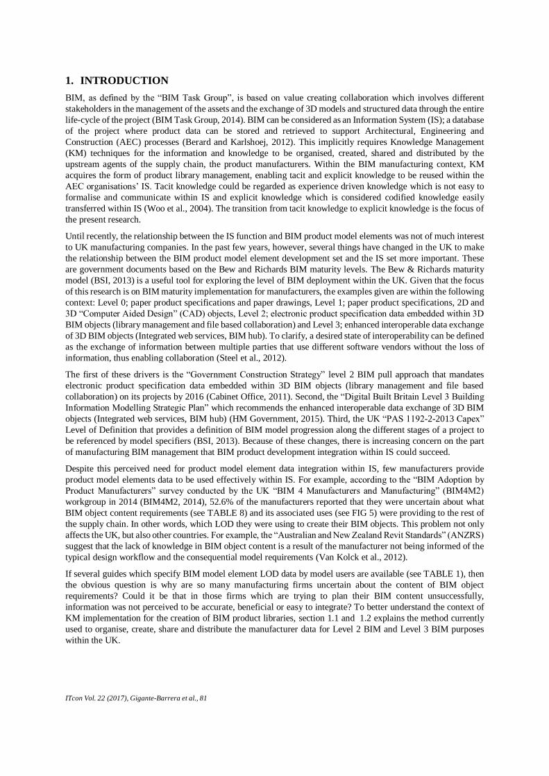
TABLE 1. Non-exhaustive list of LOD attribute guidelines.
Year Organisation and standard name Model Element Definition Inherited from
2010 [VA]The VA BIM Object Element Matrix Manual
Release v1.0 (attributes) (VA CFM, 2010)
Level of Development [AIA] 2008
2012 [NYC DDC] BIM Guidelines (NYCDDC, 2012) Level of Development [AIA] 2008
2014 [USACE] Minimum Model Element Matrix M3 v1.3
(attributes) (USACE, 2014)
Level of Development
(accuracy) and grade
Not Found
2015 [AGC, AIA, BIM Forum] LOD Specification v2015
(attributes) (BIM Forum, 2015)
Level of Development 2013 [AIA], [AGC, AIA,
BIM Forum] 2014
1.1 Product Data template
Product Data Templates (PDTs) are created by the Chartered Institute of Building Services (CIBSE) as a solution
to avoid manufacturers completing bespoke data sheets for contractors and designers. These templates are a
standardised data repository for every product type (see TABLE 8 for an example). The idea behind the PDT is to
have a standard form, which can be populated with data from the manufacturer and become a non-graphical
description of the product (CIBSE, 2015). Currently, successful BIM product library management implies the
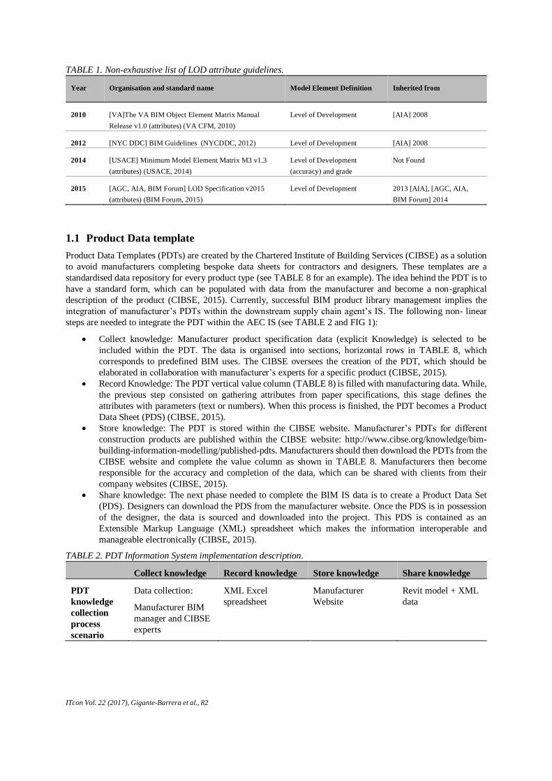
integration of manufacturer’s PDTs within the downstream supply chain agent’s IS. The following non- linear
steps are needed to integrate the PDT within the AEC IS (see TABLE 2 and FIG 1):
Collect knowledge: Manufacturer product specification data (explicit Knowledge) is selected to be
included within the PDT. The data is organised into sections, horizontal rows in TABLE 8, which
corresponds to predefined BIM uses. The CIBSE oversees the creation of the PDT, which should be
elaborated in collaboration with manufacturer’s experts for a specific product (CIBSE, 2015).
Record Knowledge: The PDT vertical value column (TABLE 8) is filled with manufacturing data. While,
the previous step consisted on gathering attributes from paper specifications, this stage defines the
attributes with parameters (text or numbers). When this process is finished, the PDT becomes a Product
Data Sheet (PDS) (CIBSE, 2015).
Store knowledge: The PDT is stored within the CIBSE website. Manufacturer’s PDTs for different
construction products are published within the CIBSE website: http://www.cibse.org/knowledge/bim-
building-information-modelling/published-pdts. Manufacturers should then download the PDTs from the
CIBSE website and complete the value column as shown in TABLE 8. Manufacturers then become
responsible for the accuracy and completion of the data, which can be shared with clients from their
company websites (CIBSE, 2015).
Share knowledge: The next phase needed to complete the BIM IS data is to create a Product Data Set
(PDS). Designers can download the PDS from the manufacturer website. Once the PDS is in possession
of the designer, the data is sourced and downloaded into the project. This PDS is contained as an
Extensible Markup Language (XML) spreadsheet which makes the information interoperable and
manageable electronically (CIBSE, 2015).
TABLE 2. PDT Information System implementation description.
Collect knowledge Record knowledge Store knowledge Share knowledge
PDT
knowledge
collection
process
scenario
Data collection:
Manufacturer BIM
manager and CIBSE
experts
XML Excel
spreadsheet
Manufacturer
Website
Revit model + XML
data
ITcon Vol. 22 (2017), Gigante-Barrera et al., 83
1.2 Information Delivery Manual
While the PDT is a solution based on collecting data from paper product specifications and transcribing them into
an electronic XML format, the IDM provides a framework for the creation and maintenance of BIM object data to
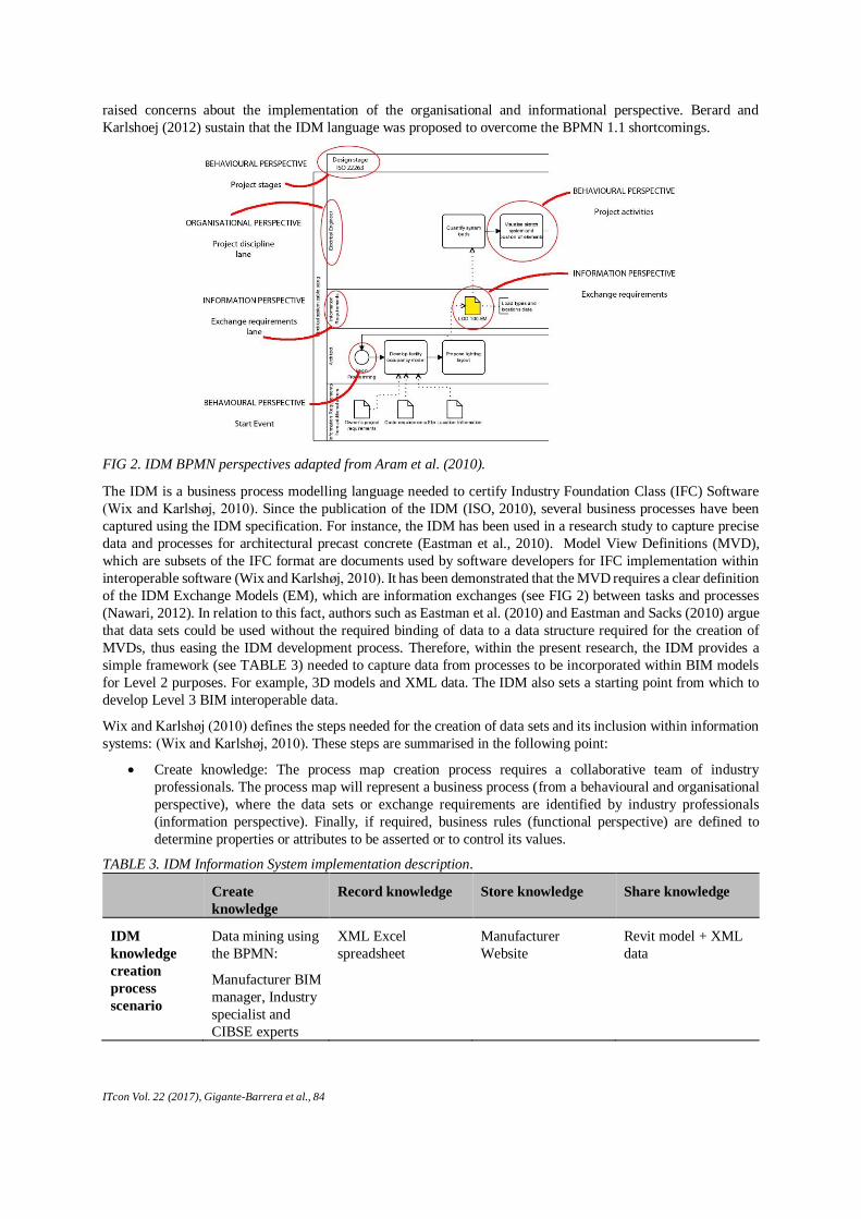
be included within IS. According to Berard and Karlshoej (2012), IDM is a business process modelling language
based on the Business Process Modelling Notattion (BPMN) which consists of the following perspectives (see
FIG 2): “process map (behavioural), narratives (organisational), exchange requirements (informational), and
narrative business rules (functional)”. Curtis et al (1992), further explains these dimensions:
The behavioural perspective represents when the processes are performed (i.e. project stage) or how they
are performed (i.e. feedback loops).
The organisational perspective represents which agents perform the process elements (i.e. engineer,
architect, and so forth).
The information perspective represents the information entities produced by a process (i.e. attributes such
as weight or object type).
Finally, the functional perspective represents what information entities are important for that process (i.e.
window width).
A review on the BPMN 1.1 conducted by Recker (2010), provided insights about the way BPMN was implemented
for process modeling. Three of the perspectives (functional, behavioural and organisational) had scope to improve,
while the information perspective was not studied. Similarly, a review carried out by List and Korherr (2006)
FIG 1. Sequence diagram of the PDT integration within the AEC IS.
ITcon Vol. 22 (2017), Gigante-Barrera et al., 84
raised concerns about the implementation of the organisational and informational perspective. Berard and
Karlshoej (2012) sustain that the IDM language was proposed to overcome the BPMN 1.1 shortcomings.
The IDM is a business process modelling language needed to certify Industry Foundation Class (IFC) Software
(Wix and Karlshøj, 2010). Since the publication of the IDM (ISO, 2010), several business processes have been
captured using the IDM specification. For instance, the IDM has been used in a research study to capture precise
data and processes for architectural precast concrete (Eastman et al., 2010). Model View Definitions (MVD),
which are subsets of the IFC format are documents used by software developers for IFC implementation within
interoperable software (Wix and Karlshøj, 2010). It has been demonstrated that the MVD requires a clear definition
of the IDM Exchange Models (EM), which are information exchanges (see FIG 2) between tasks and processes
(Nawari, 2012). In relation to this fact, authors such as Eastman et al. (2010) and Eastman and Sacks (2010) argue
that data sets could be used without the required binding of data to a data structure required for the creation of
MVDs, thus easing the IDM development process. Therefore, within the present research, the IDM provides a
simple framework (see TABLE 3) needed to capture data from processes to be incorporated within BIM models
for Level 2 purposes. For example, 3D models and XML data. The IDM also sets a starting point from which to
develop Level 3 BIM interoperable data.
Wix and Karlshøj (2010) defines the steps needed for the creation of data sets and its inclusion within information
systems: (Wix and Karlshøj, 2010). These steps are summarised in the following point:
Create knowledge: The process map creation process requires a collaborative team of industry
professionals. The process map will represent a business process (from a behavioural and organisational
perspective), where the data sets or exchange requirements are identified by industry professionals
(information perspective). Finally, if required, business rules (functional perspective) are defined to
determine properties or attributes to be asserted or to control its values.
TABLE 3. IDM Information System implementation description.
Create
knowledge
Record knowledge Store knowledge Share knowledge
IDM
knowledge
creation
process
scenario
Data mining using
the BPMN:
Manufacturer BIM
manager, Industry
specialist and
CIBSE experts
XML Excel
spreadsheet
Manufacturer
Website
Revit model + XML
data
FIG 2. IDM BPMN perspectives adapted from Aram et al. (2010).
ITcon Vol. 22 (2017), Gigante-Barrera et al., 85
2. RESEARCH PROBLEM
The PDT elaboration process claims to be a methodology to provide accurate product data for its inclusion within
IS. As mentioned within the introduction, there are several drivers within the UK that urge manufacturers to
classify product specification data according to an LOD classification (Cabinet Office, 2011, HM Government,
2015, BSI, 2013). However, PDTs are not created with the aim to specify LOD data. The present research aims to
explain the LOD integration process within manufacturers’ IS. TABLE 2 and TABLE 3 show two LOD
implementation frameworks which differ on its approach to data implementation (collection and creation of data
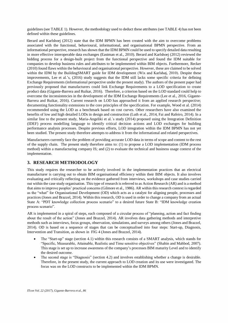
respectively). FIG 3 shows the PDT knowledge collection process scenario which requires collection of data from
manufacturer paper product specifications and LOD attributes guidelines such as the LOD Specification v2015
attributes table or the VA BIM Object Element Matrix Manual Release v1.0 among others (see TABLE 1).
However, the attributes found within these guidelines (see TABLE 4 for an example) are not sufficient to
accurately define a BIM object LOD. For example, the VA BIM Object Element Matrix Manual release v1.0
provides LOD attributes for general products such as electrical equipment. However, specific products such as
cable trays (found within manufacturer’s product specifications) would require specific attributes (gauge, finish or
maximum load), which might differ from the attributes given within these guidelines. Furthermore, these
guidelines do not provide the data context (processes). Therefore, complicating the manufacturer’s task of LOD
specification.
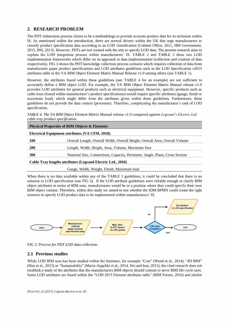
TABLE 4. The VA BIM Object Element Matrix Manual release v1.0 compared against Legrand’s Electric Ltd.
cable tray product specification.
Physical Properties of BIM Objects & Elements
Electrical Equipment attributes (VA CFM, 2010).
100 Overall Length, Overall Width, Overall Height, Overall Area, Overall Volume
200 Length, Width, Height, Area, Volume, Maximum Size
300 Nominal Size, Connections, Capacity, Perimeter, Angle, Plane, Cross Section
Cable Tray lengths attributes (Legrand Electric Ltd., 2016)
Gauge, Width, Weight, Finish, Maximum load
When there is no data available within any of the TABLE 1 guidelines, it could be concluded that there is no
solution to LOD specification (see FIG 3). If the LOD attribute guidelines were reliable enough to clarify BIM
object attributes in terms of BIM uses, manufacturers would be in a position where they could specify their own
BIM object content. Therefore, within this study we aimed to test whether the IDM BPMN could create the right
scenario to specify LOD product data to be implemented within manufacturers’ IS.
2.1 Previous studies
While LOD BIM uses has been studied within the literature, for example “Cost” (Wood et al., 2014), “4D BIM”
(Han et al., 2015) or “Sustainability” (Maria-Angeliki et al., 2014, Wu and Issa, 2015), the cited research does not
establish a study of the attributes that the manufacturers BIM objects should contain to serve BIM life-cycle uses.
Some LOD attributes are found within the “LOD 2015 Element attributes table” (BIM Forum, 2016) and similar
FIG 3. Process for PDT LOD data collection.
ITcon Vol. 22 (2017), Gigante-Barrera et al., 86
guidelines (see TABLE 1). However, the methodology used to deduct these attributes (see TABLE 4) has not been
defined within these guidelines.
Berard and Karlshoej (2012) state that the IDM BPMN has been created with the aim to overcome problems
associated with the functional, behavioural, informational, and organisational BPMN perspective. From an
informational perspective, research has shown that the IDM BPMN could be used to specify detailed data resulting
in more effective interoperable data exchanges (Eastman et al., 2010). Berard and Karlshoej (2012) reviewed the
bidding process for a design-built project from the functional perspective and found the IDM suitable for
companies to develop business rules and attributes to be implemented within BIM objects. Furthermore, Recker
(2010) found flaws within the behavioural and organisational perspective. However, these are claimed to be solved
within the IDM by the BuildingSMART guide for IDM development (Wix and Karlshøj, 2010). Despite these
improvements, Lee et al.’s, (2016) study suggests that the IDM still lacks some specific criteria for defining
Exchange Requirements (informational perspective under the present study). The authors of the present paper had
previously proposed that manufacturers could link Exchange Requirements to a LOD specification to create
product data (Gigante-Barrera and Ruikar, 2016). Therefore, a criterion based on the LOD standard could help to
overcome the inconsistencies in the development of the IDM Exchange Requirements (Lee et al., 2016, Gigante-
Barrera and Ruikar, 2016). Current research on LOD has approached it from an applied research perspective;
documenting functionality extensions to the core principles of the specification. For example, Wood et al. (2014)
recommended using the LOD as a benchmark based on cost curves. Other researchers have also examined the
benefits of low and high detailed LODs in design and construction (Luth et al., 2014, Fai and Rafeiro, 2014). In a
similar line to the present study, Maria-Angeliki et al.´s study (2014) proposed using the Integration Definition
(IDEF) process modelling language to identify critical decision actions and LOD exchanges for building
performance analysis processes. Despite previous efforts, LOD integration within the IDM BPMN has not yet
been studied. The present study therefore attempts to address it from the informational and related perspectives.
Manufacturers currently face the problem of providing accurate LOD data in terms of scope and content to the rest
of the supply chain. The present study therefore aims to: (1) to propose a LOD implementation (IDM process
method) within a manufacturing company IS; and (2) to evaluate the technical and business usage context of the
implementation.
3. RESEARCH METHODOLOGY
This study requires the researcher to be actively involved in the implementation practices that an electrical
manufacturer is carrying out to obtain BIM organisational efficiency within their BIM objects. It also involves
evaluating and critically reflecting on the evidence gathered from interviews, workshops and case studies carried
out within the case study organisation. This type of research is referred to as Action Research (AR) and is a method
that aims to improve peoples’ practical concerns (Gilmore et al., 1986). AR within this research context is regarded
as the “what” for Organisational Development (OD) which acts as a catalyst for aligning people, processes and
practices (Jones and Brazzel, 2014). Within this research, OD is used in order to change a company from an actual
State A: “PDT knowledge collection process scenario” to a desired future State B: “IDM knowledge creation
process scenario”.
AR is implemented in a spiral of steps, each composed of a circular process of “planning, action and fact finding
about the result of the action” (Jones and Brazzel, 2014). AR involves data gathering methods and interpretive
methods such as interviews, focus groups, observation, simulations, and surveys among others (Jones and Brazzel,
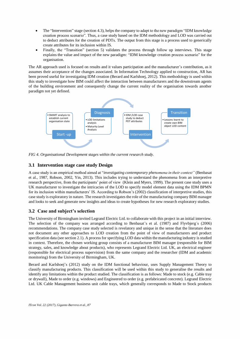
2014). OD is based on a sequence of stages that can be conceptualised into four steps: Start-up, Diagnosis,
Intervention and Transition, as shown in FIG 4 (Jones and Brazzel, 2014).
The “Start-up” stage (section 4.1) within this research consists of a SMART analysis, which stands for
“Specific, Measurable, Attainable, Realistic and Time sensitive objectives” (Shahin and Mahbod, 2007).
This stage is set up to increase awareness of the company’s processes BIM maturity Level and to identify
the desired outcome.
The second stage is “Diagnosis” (section 4.2) and involves establishing whether a change is desirable.
Therefore, in the present study, the current approach to LOD creation and its use were investigated. The
focus was on the LOD constructs to be implemented within the IDM BPMN.
ITcon Vol. 22 (2017), Gigante-Barrera et al., 87
The “Intervention” stage (section 4.3), helps the company to adapt to the new paradigm “IDM knowledge
creation process scenario”. Thus, a case study based on the IDM methodology and LOD was carried out
to deduct attributes for the creation of PDTs. The output from this stage is a process used to generically
create attributes for its inclusion within IS.
Finally, the “Transition” (section 5) validates the process through follow up interviews. This stage
explains the value and impact of the new paradigm: “IDM knowledge creation process scenario” for the
organisation.
The AR approach used is focused on results and it values participation and the manufacturer’s contribution, as it
assumes their acceptance of the changes associated. In Information Technology applied to construction, AR has
been proved useful for investigating IDM creation (Berard and Karlshoej, 2012). This methodology is used within
this study to investigate how BIM could affect the interaction between manufacturers and the downstream agents
of the building environment and consequently change the current reality of the organisation towards another
paradigm not yet defined.
3.1 Intervention stage case study Design
A case study is an empirical method aimed at “investigating contemporary phenomena in their context” (Benbasat
et al., 1987, Robson, 2002, Yin, 2013). This includes trying to understand the phenomena from an interpretive
research perspective, from the participants’ point of view (Klein and Myers, 1999). The present case study uses a
UK manufacturer to investigate the intricacies of the LOD to specify model element data using the IDM BPMN
for its inclusion within manufacturers’ IS. According to Robson’s (2002) classification of interpretive studies, this
case study is exploratory in nature. The research investigates the role of the manufacturing company BIM manager
and looks to seek and generate new insights and ideas to create hypotheses for new research exploratory studies.
3.2 Case and subject’s selection
The University of Birmingham invited Legrand Electric Ltd. to collaborate with this project in an initial interview.
The selection of the company was arranged according to Benbasat’s et al. (1987) and Flyvbjerg´s (2006)
recommendations. The company case study selected is revelatory and unique in the sense that the literature does
not document any other approaches to LOD creation from the point of view of manufacturers and product
specification data (see section 2.1). A process for specifying LOD data within the manufacturing industry is studied
in context. Therefore, the chosen working group consists of a manufacturer BIM manager (responsible for BIM
strategy, sales, and knowledge about products), who represents Legrand Electric Ltd. UK, an electrical engineer
(responsible for electrical process supervision) from the same company and the researcher (IDM and academic
monitoring) from the University of Birmingham, UK.
Berard and Karlshoej’s (2012) study on the IDM functional behaviour, uses Supply Management Theory to
classify manufacturing products. This classification will be used within this study to generalise the results and
identify any limitations within the product studied. The classification is as follows: Made to stock (e.g. Cable tray
or drywall), Made to order (e.g. windows) and Engineered to order (e.g. prefabricated concrete). Legrand Electric
Ltd. UK Cable Management business unit cable trays, which generally corresponds to Made to Stock products
• SMART analysis to establish current organisation state
Start -up
• LOD limitations analysis
•Maturity Level Analysis
Diagnosis• IDM /LOD case
study to deduct PDT attributes
Intervention
• Lessons learnt to create own BIM object LOD content
Transition
FIG 4. Organisational Development stages within the current research study.

ITcon Vol. 22 (2017), Gigante-Barrera et al., 88
was studied. This product was studied in conjunction with cables because cable tray BIM models inherit properties
from them. Made to Stock product were selected as per availability and easiness to deduct attributes.
4. RESULTS OF THE ORGANISATIONAL DEVELOPMENT PROCESS
4.1 Start-up stage
The target company (Legrand Electric LTD.) is a global electrical product manufacturer with presence in nearly
90 countries around the world. The research group consists of a BIM Manager, an electrical engineer and a doctoral
researcher. A SMART analysis was conducted to establish the project boundaries. The conclusions of this analysis
are the following: One of the company’s objective is to educate itself in BIM processes relating to data exchanges,
which in turn will ensure that Legrand can continue to be specified by their key stakeholders. In the case of the
UK, the Government strategy requires Level 2 BIM for all public asset procurement (Cabinet Office, 2011). For
2016, the cable management business unit agreed to provide 3D models with non-graphical specification attached
to them. To do so, the company engaged with the CIBSE initiative to provide Level 2 PDTs. These contain product
attributes such as the ones found within the paper product specifications. Previous processes consisted of providing
2D CAD drawings and paper specifications to their clients, which is known as Level 1 BIM. It was understood
that the aim of the meetings was to record the process and extract valuable lessons, drivers and barriers relating to
the implementation of BIM using the OD strategy described in the methodology section. This is necessary in order
to increase knowledge of their own BIM objects value, which has been found to be contractual support,
interoperability support and software development support.
4.2 Diagnosis
This stage is set to share the understanding of the system involving the project and to decide if there is a potential
need for change (Jones and Brazzel, 2014). From the outset of the project it was understood that BIM may change
some of their processes. As the company’s BIM Manger stated: “BIM has already affected some of the ways in
which we are looking at how we deliver data, which is the first step in BIM really, that’s delivering that data”
(Gigante-Barrera, 2014). LOD is one of the most cited graphical and non-graphical standards within the literature
(Staub-French and Khanzode, 2007, Eastman et al., 2011, Maria-Angeliki et al., 2014, Wood et al., 2014, Han et
al., 2015, Hooper, 2015, Wu and Issa, 2015). This is the reason its usefulness for manufacturers has been analysed
in section 4.2.1. However, other definitions are available depending on the country or institution which defines it.
For example, in the UK, the PAS 1192: 2013 is the guideline used to define the BIM object information referred
to as the Level of Definition (BIM4M2, 2014). Both concepts contain intrinsic constructs such as stage, LOD
number of definitions and BIM use, which are compared for their inclusion within the IDM BPMN.
4.2.1 USA Level of Development and UK Level of Definition
The LOD to be included within the definition of a BIM object is a critical criterion for manufacturers (BIM4M2,
2014). The “AIA G202-2013, Project Building Information Modelling Protocol Form” was created by the
“American Institute of Architects (AIA) California Council Integrated Project Delivery Task Force”. The “AIA
G202-2013” LOD allows for “Model Element” specification of content requirements and its associated uses. It is
divided into five different progressive levels that specify the detail of completeness within the element (AIA,
2013). Similarly, the “Specification BIM Forum” in the “Level of Development Specification 2015”document
(BIM Forum, 2015), utilises the AIA LOD definitions found in the “AIA G202-2013”. In contrast to the “AIA
G202-2013”, it expands the AIA’s LOD definition by including a LOD 350 required for coordination between
disciplines (BIM Forum, 2015). Interestingly, the “G202-2013” propose several authorised uses such as
“Analysis”, “Cost”, “Estimating” and “schedule”, leaving room to assign other uses by the interested stakeholder
(AIA, 2013). While the “G202-2013” LOD defines a basic standard, the “Level of Development Specification
2015” document, defines and illustrates LODs by product which help teams to specify deliverables. This
specification addresses the definition of components by describing requirements. They can be included in contracts
and can also help managers to explain to teams which information should be included in the project at different
stages (BIM Forum, 2015). As an example, the “Level of Development Specification 2015” LOD’s description for
“Branch wiring System” elements is found below:
LOD 100 - “Schematic model element” and “Schematic layout”.
ITcon Vol. 22 (2017), Gigante-Barrera et al., 89
LOD 200 - “Schematic layout with approximate size, shape and location of equipment”;
“Approximate access/code clearance requirements modelled”
LOD 300 – “Modelled as design-specified size, shape, spacing and location of raceways boxes
and enclosures; “Approximate allowances for spacing and clearances required for all specified
hangers, supports and seismic control; actual access/code clearance requirements modelled”.
LOD 350 – “Modelled as actual size, shape, spacing, and location of raceways, boxes,
enclosures”; “Actual size, shape, spacing, and location for supports and seismic control”;
“Actual floor and wall penetrations are modelled”.
LOD 400 – “Supplementary components added to the model required for fabrication and field
installation”.
Similarly, The PAS 1192: 2013 was created by the British Standards Institution in the UK (BSI, 2013). PAS 1192:
2013 includes BIM models descriptions that are articulated around Levels of Definition. These Levels of
Definition, which includes narratives, describe the general information that should be included within BIM models.
Differently to the “G202-2013”, the Levels of Definition are linked to project stages, for example the CIC Scope
of Services provides a standard classification. The definitions are as follows: Brief, Concept, Design, Definition,
Design, Build and Commissioning, Handover and Closeout. TABLE 5 shows graphical 3D BIM models contained
within the “Level of Development Specification 2015” and the PAS 1192:2013 respectively. While the first gives
specific examples per product, the second provides a general description of what level to achieve at each project
stage.
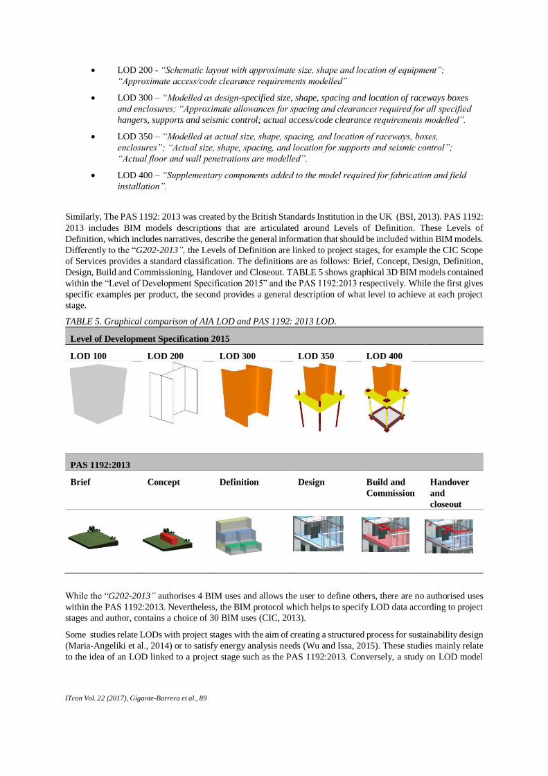
TABLE 5. Graphical comparison of AIA LOD and PAS 1192: 2013 LOD.
Level of Development Specification 2015
LOD 100 LOD 200 LOD 300 LOD 350 LOD 400
PAS 1192:2013
Brief Concept Definition Design Build and
Commission
Handover
and
closeout
While the “G202-2013” authorises 4 BIM uses and allows the user to define others, there are no authorised uses
within the PAS 1192:2013. Nevertheless, the BIM protocol which helps to specify LOD data according to project
stages and author, contains a choice of 30 BIM uses (CIC, 2013).
Some studies relate LODs with project stages with the aim of creating a structured process for sustainability design
(Maria-Angeliki et al., 2014) or to satisfy energy analysis needs (Wu and Issa, 2015). These studies mainly relate
to the idea of an LOD linked to a project stage such as the PAS 1192:2013. Conversely, a study on LOD model
ITcon Vol. 22 (2017), Gigante-Barrera et al., 90
progression using the AIA LOD concept, states that the LOD should be free of stage bindings (Hooper, 2015).
Other studies suggest that the LOD depends on the BIM use or application (Staub-French and Khanzode, 2007,
Eastman et al., 2011). For example, the “G202-2013” LOD binds the LOD concept to authorised uses as explained
previously. From the manufacturers’ point of view, BIM object level approaches to LOD are needed in order to
take full advantage of BIM objects in terms of value, such as object-based software development (MVD), BIM
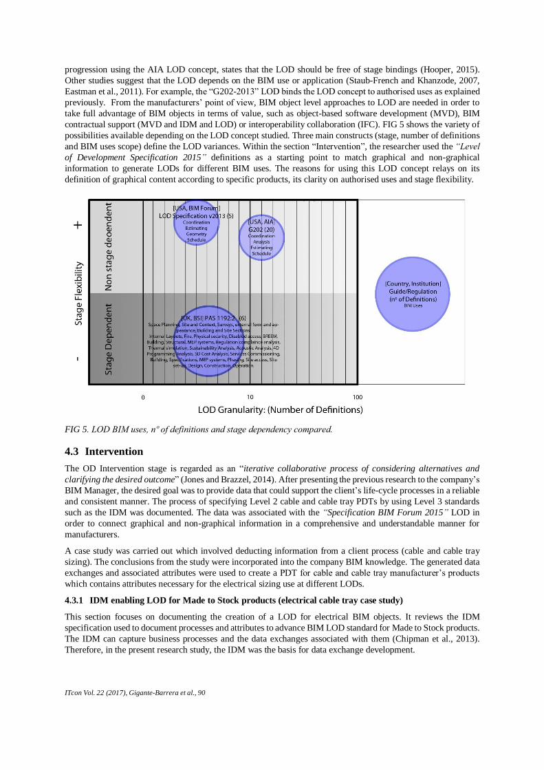
contractual support (MVD and IDM and LOD) or interoperability collaboration (IFC). FIG 5 shows the variety of
possibilities available depending on the LOD concept studied. Three main constructs (stage, number of definitions
and BIM uses scope) define the LOD variances. Within the section “Intervention”, the researcher used the “Level
of Development Specification 2015” definitions as a starting point to match graphical and non-graphical
information to generate LODs for different BIM uses. The reasons for using this LOD concept relays on its
definition of graphical content according to specific products, its clarity on authorised uses and stage flexibility.
4.3 Intervention
The OD Intervention stage is regarded as an “iterative collaborative process of considering alternatives and
clarifying the desired outcome” (Jones and Brazzel, 2014). After presenting the previous research to the company’s
BIM Manager, the desired goal was to provide data that could support the client’s life-cycle processes in a reliable
and consistent manner. The process of specifying Level 2 cable and cable tray PDTs by using Level 3 standards
such as the IDM was documented. The data was associated with the “Specification BIM Forum 2015” LOD in
order to connect graphical and non-graphical information in a comprehensive and understandable manner for
manufacturers.
A case study was carried out which involved deducting information from a client process (cable and cable tray
sizing). The conclusions from the study were incorporated into the company BIM knowledge. The generated data
exchanges and associated attributes were used to create a PDT for cable and cable tray manufacturer’s products
which contains attributes necessary for the electrical sizing use at different LODs.
4.3.1 IDM enabling LOD for Made to Stock products (electrical cable tray case study)
This section focuses on documenting the creation of a LOD for electrical BIM objects. It reviews the IDM
specification used to document processes and attributes to advance BIM LOD standard for Made to Stock products.
The IDM can capture business processes and the data exchanges associated with them (Chipman et al., 2013).
Therefore, in the present research study, the IDM was the basis for data exchange development.
FIG 5. LOD BIM uses, nº of definitions and stage dependency compared.
ITcon Vol. 22 (2017), Gigante-Barrera et al., 91
The IDM creation begins with the definition of “Process Maps” (PM) (see FIG 2). In the present research, the PM
describes a particular flow of activities within the electrical cable sizing process. PMs are diagrammatically
represented as single “pools” and the name of the pool describes the PM. The description and identification of the
information from the data involved within the business processes at a particular stage of the project is depicted
within “Exchange requirements” (ERs). The workflows scenarios and the ERs between the actors “architects” and
“electrical engineers”, are represented in single “lanes” contained within the PM “Pool”(Wix and Karlshøj, 2010).
This is illustrated in the PM shown in FIG 7. The process of developing an IDM requires a first step of “process
discovering and data mining” (Wix and Karlshøj, 2010). The “Level of Development Specification 2015” was used
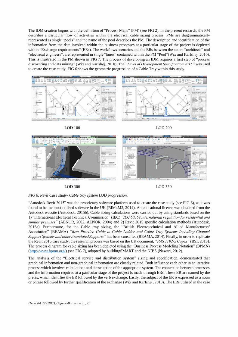
to create the case study. FIG 6 shows the geometric progression of a Cable Tray within this study.
“Autodesk Revit 2015” was the proprietary software platform used to create the case study (see FIG 6), as it was
found to be the most utilised software in the UK (BIM4M2, 2014). An educational license was obtained from the
Autodesk website (Autodesk, 2015b). Cable sizing calculations were carried out by using standards based on the
1) “International Electrical Technical Commission” (IEC) “IEC 60364 international regulation for residential and
similar premises” (AENOR, 2002, AENOR, 2004) and 2) Revit 2015 specific calculation methods (Autodesk,
2015a). Furthermore, for the Cable tray sizing, the “British Electrotechnical and Allied Manufacturers'
Association” (BEAMA) “Best Practice Guide to Cable Ladder and Cable Tray Systems Including Channel
Support Systems and other Associated Supports” has been consulted (BEAMA, 2014). Finally, in order to replicate
the Revit 2015 case study, the research process was based on the UK document, “PAS 1192-2 Capex” (BSI, 2013).
The process diagram for cable sizing has been depicted using the “Business Process Modeling Notation” (BPMN)
(http://www.bpmn.org/) (see FIG 7), adopted by buildingSMART and the NIBS (Nawari, 2012).
The analysis of the “Electrical service and distribution system” sizing and specification, demonstrated that
graphical information and non-graphical information are closely related. Both influence each other in an iterative
process which involves calculations and the selection of the appropriate system. The connection between processes
and the information required at a particular stage of the project is made through ERs. These ER are named by the
prefix, which identifies the ER followed by the verb exchange. Lastly, the subject of the ER is expressed as a noun
or phrase followed by further qualification of the exchange (Wix and Karlshøj, 2010). The ERs utilised in the case
FIG 6. Revit Case study- Cable tray system LOD progression.
ITcon Vol. 22 (2017), Gigante-Barrera et al., 92
study has been coordinated with the LOD cable definition from the “Specification BIM Forum Level of
Development Specification” (BIM Forum, 2015). This helped to increase understanding of how BIM model’s data
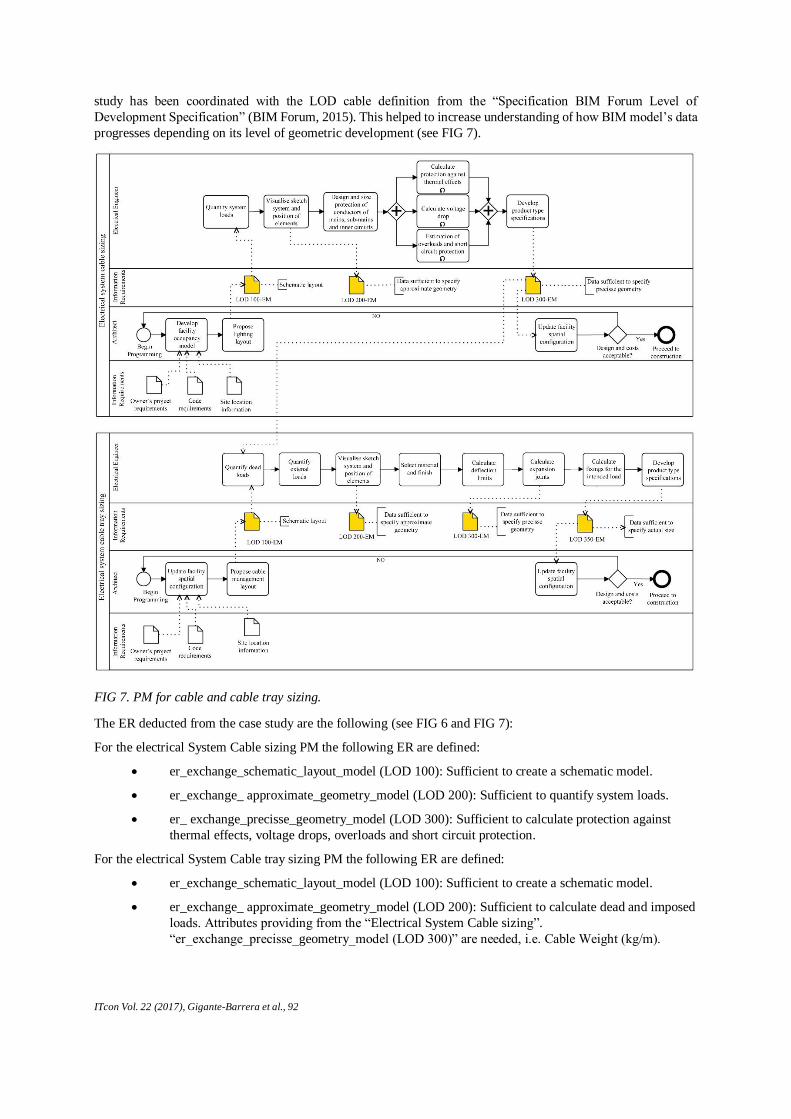
progresses depending on its level of geometric development (see FIG 7).
The ER deducted from the case study are the following (see FIG 6 and FIG 7):
For the electrical System Cable sizing PM the following ER are defined:
er_exchange_schematic_layout_model (LOD 100): Sufficient to create a schematic model.
er_exchange_ approximate_geometry_model (LOD 200): Sufficient to quantify system loads.
er_ exchange_precisse_geometry_model (LOD 300): Sufficient to calculate protection against
thermal effects, voltage drops, overloads and short circuit protection.
For the electrical System Cable tray sizing PM the following ER are defined:
er_exchange_schematic_layout_model (LOD 100): Sufficient to create a schematic model.
er_exchange_ approximate_geometry_model (LOD 200): Sufficient to calculate dead and imposed
loads. Attributes providing from the “Electrical System Cable sizing”.
“er_exchange_precisse_geometry_model (LOD 300)” are needed, i.e. Cable Weight (kg/m).
FIG 7. PM for cable and cable tray sizing.
ITcon Vol. 22 (2017), Gigante-Barrera et al., 93
er_ exchange_precisse_geometry_model (LOD 300): Sufficient to select material and finish, to
calculate deflection limits and expansion joints.
er_ exchange_actual_geometry_model (LOD 350): Sufficient to calculate fixings for the intended
load.
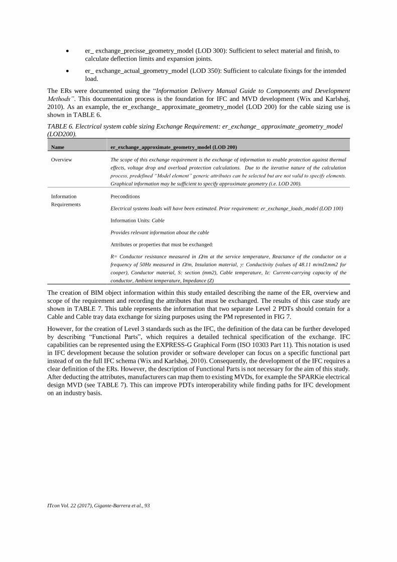
The ERs were documented using the “Information Delivery Manual Guide to Components and Development
Methods”. This documentation process is the foundation for IFC and MVD development (Wix and Karlshøj,
2010). As an example, the er_exchange_ approximate_geometry_model (LOD 200) for the cable sizing use is
shown in TABLE 6.
TABLE 6. Electrical system cable sizing Exchange Requirement: er_exchange_ approximate_geometry_model
(LOD200).
Name er_exchange_approximate_geometry_model (LOD 200)
Overview The scope of this exchange requirement is the exchange of information to enable protection against thermal
effects, voltage drop and overload protection calculations. Due to the iterative nature of the calculation
process, predefined “Model element” generic attributes can be selected but are not valid to specify elements.
Graphical information may be sufficient to specify approximate geometry (i.e. LOD 200).
Information
Requirements
Preconditions
Electrical systems loads will have been estimated. Prior requirement: er_exchange_loads_model (LOD 100)
Information Units: Cable
Provides relevant information about the cable
Attributes or properties that must be exchanged:
R= Conductor resistance measured in /m at the service temperature, Reactance of the conductor on a
frequency of 50Hz measured in /m, Insulation material, : Conductivity (values of 48.11 m/m.mm2 for
cooper), Conductor material, S: section (mm2), Cable temperature, Iz: Current-carrying capacity of the
conductor, Ambient temperature, Impedance (Z)
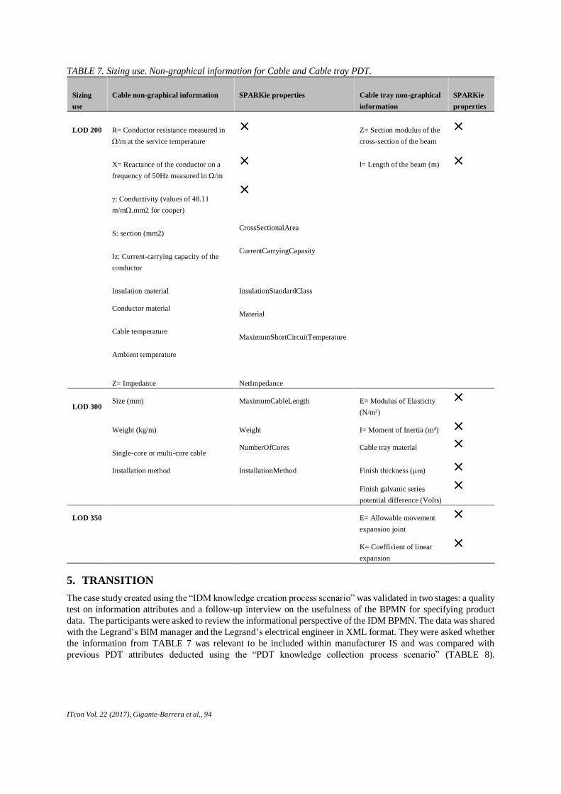
The creation of BIM object information within this study entailed describing the name of the ER, overview and
scope of the requirement and recording the attributes that must be exchanged. The results of this case study are
shown in TABLE 7. This table represents the information that two separate Level 2 PDTs should contain for a
Cable and Cable tray data exchange for sizing purposes using the PM represented in FIG 7.
However, for the creation of Level 3 standards such as the IFC, the definition of the data can be further developed
by describing “Functional Parts”, which requires a detailed technical specification of the exchange. IFC
capabilities can be represented using the EXPRESS-G Graphical Form (ISO 10303 Part 11). This notation is used
in IFC development because the solution provider or software developer can focus on a specific functional part
instead of on the full IFC schema (Wix and Karlshøj, 2010). Consequently, the development of the IFC requires a
clear definition of the ERs. However, the description of Functional Parts is not necessary for the aim of this study.
After deducting the attributes, manufacturers can map them to existing MVDs, for example the SPARKie electrical
design MVD (see TABLE 7). This can improve PDTs interoperability while finding paths for IFC development
on an industry basis.
ITcon Vol. 22 (2017), Gigante-Barrera et al., 94
TABLE 7. Sizing use. Non-graphical information for Cable and Cable tray PDT.
Sizing
use
Cable non-graphical information SPARKie properties Cable tray non-graphical
information
SPARKie
properties
LOD 200
R= Conductor resistance measured in
/m at the service temperature
× Z= Section modulus of the
cross-section of the beam
×
X= Reactance of the conductor on a
frequency of 50Hz measured in /m
× l= Length of the beam (m) ×
: Conductivity (values of 48.11
m/m.mm2 for cooper)
×
S: section (mm2) CrossSectionalArea
Iz: Current-carrying capacity of the
conductor
CurrentCarryingCapasity
Insulation material InsulationStandardClass
Conductor material Material
Cable temperature MaximumShortCircuitTemperature
Ambient temperature
Z= Impedance NetImpedance
LOD 300
Size (mm) MaximumCableLength E= Modulus of Elasticity
(N/m2)
×
Weight (kg/m) Weight I= Moment of Inertia (m4) ×
Single-core or multi-core cable NumberOfCores Cable tray material ×
Installation method InstallationMethod Finish thickness (µm) ×
Finish galvanic series
potential difference (Volts)
×
LOD 350 E= Allowable movement
expansion joint
×
K= Coefficient of linear
expansion
×
5. TRANSITION
The case study created using the “IDM knowledge creation process scenario” was validated in two stages: a quality
test on information attributes and a follow-up interview on the usefulness of the BPMN for specifying product
data. The participants were asked to review the informational perspective of the IDM BPMN. The data was shared
with the Legrand’s BIM manager and the Legrand’s electrical engineer in XML format. They were asked whether
the information from TABLE 7 was relevant to be included within manufacturer IS and was compared with
previous PDT attributes deducted using the “PDT knowledge collection process scenario” (TABLE 8).
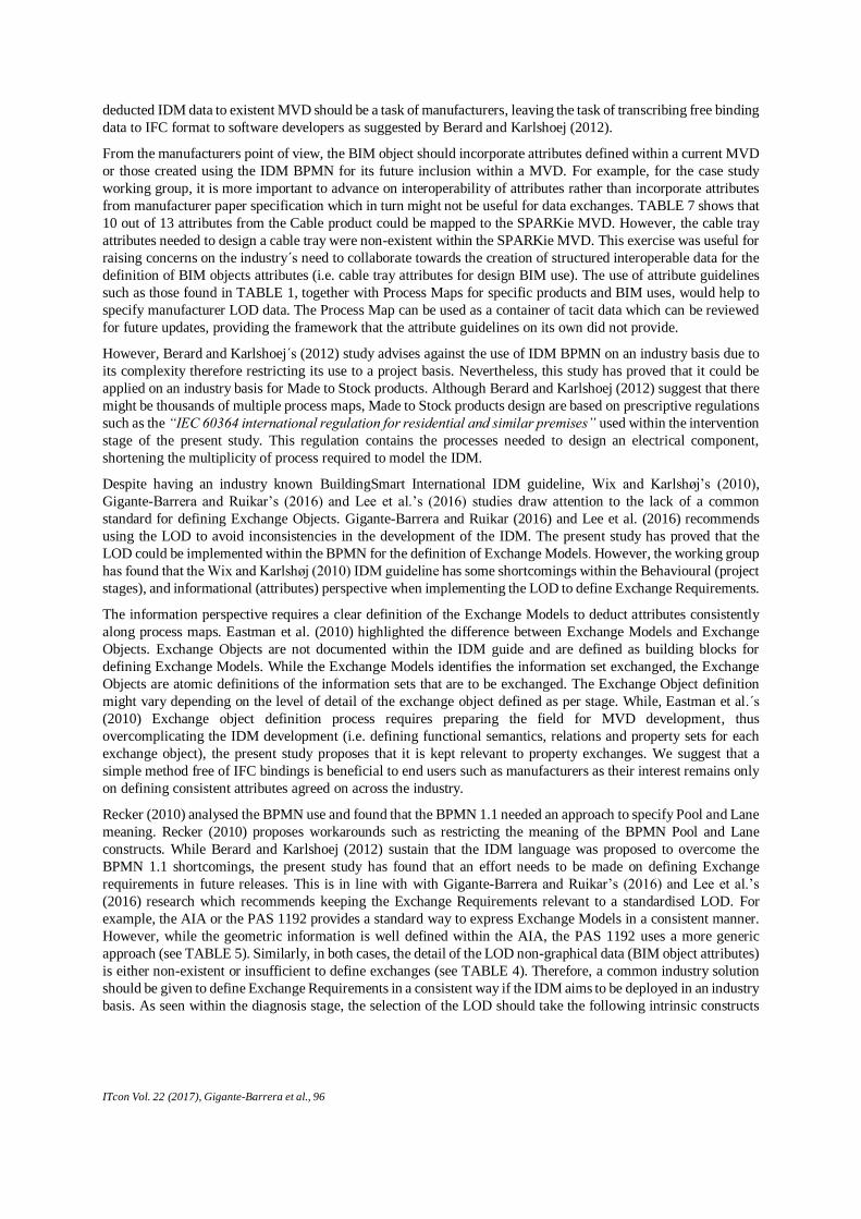
ITcon Vol. 22 (2017), Gigante-Barrera et al., 95
Furthermore, they were asked to give feedback on the behavioural and organisational perspective of the IDM
BPMN for the implementation of the LOD.
5.1 Discussion
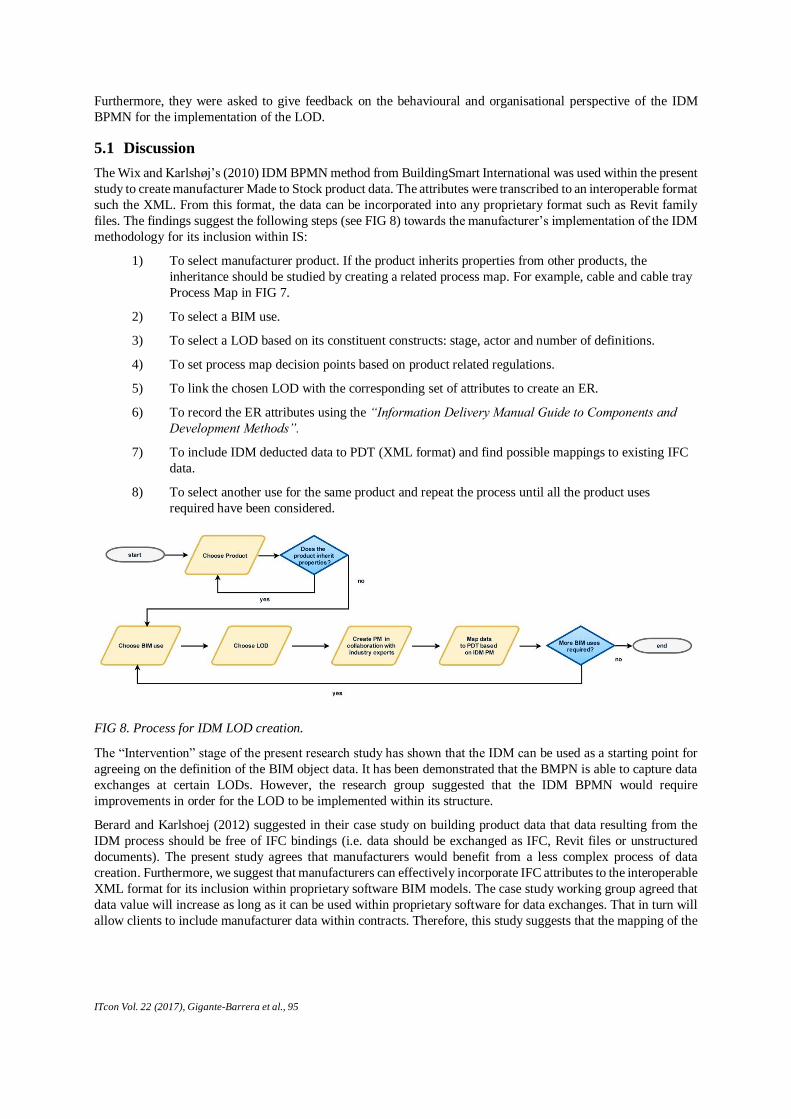
The Wix and Karlshøj’s (2010) IDM BPMN method from BuildingSmart International was used within the present
study to create manufacturer Made to Stock product data. The attributes were transcribed to an interoperable format
such the XML. From this format, the data can be incorporated into any proprietary format such as Revit family
files. The findings suggest the following steps (see FIG 8) towards the manufacturer’s implementation of the IDM
methodology for its inclusion within IS:
1) To select manufacturer product. If the product inherits properties from other products, the
inheritance should be studied by creating a related process map. For example, cable and cable tray
Process Map in FIG 7.
2) To select a BIM use.
3) To select a LOD based on its constituent constructs: stage, actor and number of definitions.
4) To set process map decision points based on product related regulations.
5) To link the chosen LOD with the corresponding set of attributes to create an ER.
6) To record the ER attributes using the “Information Delivery Manual Guide to Components and
Development Methods”.
7) To include IDM deducted data to PDT (XML format) and find possible mappings to existing IFC
data.
8) To select another use for the same product and repeat the process until all the product uses
required have been considered.
The “Intervention” stage of the present research study has shown that the IDM can be used as a starting point for
agreeing on the definition of the BIM object data. It has been demonstrated that the BMPN is able to capture data
exchanges at certain LODs. However, the research group suggested that the IDM BPMN would require
improvements in order for the LOD to be implemented within its structure.
Berard and Karlshoej (2012) suggested in their case study on building product data that data resulting from the
IDM process should be free of IFC bindings (i.e. data should be exchanged as IFC, Revit files or unstructured
documents). The present study agrees that manufacturers would benefit from a less complex process of data
creation. Furthermore, we suggest that manufacturers can effectively incorporate IFC attributes to the interoperable
XML format for its inclusion within proprietary software BIM models. The case study working group agreed that
data value will increase as long as it can be used within proprietary software for data exchanges. That in turn will
allow clients to include manufacturer data within contracts. Therefore, this study suggests that the mapping of the
FIG 8. Process for IDM LOD creation.
ITcon Vol. 22 (2017), Gigante-Barrera et al., 96
deducted IDM data to existent MVD should be a task of manufacturers, leaving the task of transcribing free binding
data to IFC format to software developers as suggested by Berard and Karlshoej (2012).
From the manufacturers point of view, the BIM object should incorporate attributes defined within a current MVD
or those created using the IDM BPMN for its future inclusion within a MVD. For example, for the case study
working group, it is more important to advance on interoperability of attributes rather than incorporate attributes
from manufacturer paper specification which in turn might not be useful for data exchanges. TABLE 7 shows that
10 out of 13 attributes from the Cable product could be mapped to the SPARKie MVD. However, the cable tray
attributes needed to design a cable tray were non-existent within the SPARKie MVD. This exercise was useful for
raising concerns on the industry´s need to collaborate towards the creation of structured interoperable data for the
definition of BIM objects attributes (i.e. cable tray attributes for design BIM use). The use of attribute guidelines
such as those found in TABLE 1, together with Process Maps for specific products and BIM uses, would help to
specify manufacturer LOD data. The Process Map can be used as a container of tacit data which can be reviewed
for future updates, providing the framework that the attribute guidelines on its own did not provide.
However, Berard and Karlshoej´s (2012) study advises against the use of IDM BPMN on an industry basis due to
its complexity therefore restricting its use to a project basis. Nevertheless, this study has proved that it could be
applied on an industry basis for Made to Stock products. Although Berard and Karlshoej (2012) suggest that there
might be thousands of multiple process maps, Made to Stock products design are based on prescriptive regulations
such as the “IEC 60364 international regulation for residential and similar premises” used within the intervention
stage of the present study. This regulation contains the processes needed to design an electrical component,
shortening the multiplicity of process required to model the IDM.
Despite having an industry known BuildingSmart International IDM guideline, Wix and Karlshøj’s (2010),
Gigante-Barrera and Ruikar’s (2016) and Lee et al.’s (2016) studies draw attention to the lack of a common
standard for defining Exchange Objects. Gigante-Barrera and Ruikar (2016) and Lee et al. (2016) recommends
using the LOD to avoid inconsistencies in the development of the IDM. The present study has proved that the
LOD could be implemented within the BPMN for the definition of Exchange Models. However, the working group
has found that the Wix and Karlshøj (2010) IDM guideline has some shortcomings within the Behavioural (project
stages), and informational (attributes) perspective when implementing the LOD to define Exchange Requirements.
The information perspective requires a clear definition of the Exchange Models to deduct attributes consistently
along process maps. Eastman et al. (2010) highlighted the difference between Exchange Models and Exchange
Objects. Exchange Objects are not documented within the IDM guide and are defined as building blocks for
defining Exchange Models. While the Exchange Models identifies the information set exchanged, the Exchange
Objects are atomic definitions of the information sets that are to be exchanged. The Exchange Object definition
might vary depending on the level of detail of the exchange object defined as per stage. While, Eastman et al.´s
(2010) Exchange object definition process requires preparing the field for MVD development, thus
overcomplicating the IDM development (i.e. defining functional semantics, relations and property sets for each
exchange object), the present study proposes that it is kept relevant to property exchanges. We suggest that a
simple method free of IFC bindings is beneficial to end users such as manufacturers as their interest remains only
on defining consistent attributes agreed on across the industry.
Recker (2010) analysed the BPMN use and found that the BPMN 1.1 needed an approach to specify Pool and Lane
meaning. Recker (2010) proposes workarounds such as restricting the meaning of the BPMN Pool and Lane
constructs. While Berard and Karlshoej (2012) sustain that the IDM language was proposed to overcome the
BPMN 1.1 shortcomings, the present study has found that an effort needs to be made on defining Exchange
requirements in future releases. This is in line with with Gigante-Barrera and Ruikar’s (2016) and Lee et al.’s
(2016) research which recommends keeping the Exchange Requirements relevant to a standardised LOD. For
example, the AIA or the PAS 1192 provides a standard way to express Exchange Models in a consistent manner.
However, while the geometric information is well defined within the AIA, the PAS 1192 uses a more generic
approach (see TABLE 5). Similarly, in both cases, the detail of the LOD non-graphical data (BIM object attributes)
is either non-existent or insufficient to define exchanges (see TABLE 4). Therefore, a common industry solution
should be given to define Exchange Requirements in a consistent way if the IDM aims to be deployed in an industry
basis. As seen within the diagnosis stage, the selection of the LOD should take the following intrinsic constructs
ITcon Vol. 22 (2017), Gigante-Barrera et al., 97
into account: stage, number of definitions and actors (see FIG 5). The wide range of options could affect the
behavioural perspective of the BPMN.
The behavioural perspective is well addressed within the BuildingSmart International IDM guideline (Wix and
Karlshøj, 2010). In line with Recker’s (2010) recommendations, the meaning of project stages was restricted. For
example, to clarify project stages meaning, the IDM guide utilises a list of stages based on the Generic Process
protocol (Wix and Karlshøj, 2010). However, this study uses the LOD as a standard to define Exchange
Requirements. Therefore, the BPMN should adapt to this change. In order to reduce required Process Maps and
for its ease of use on an industry basis, this study proposes keeping the Process Maps free of stage bindings. For
example, the design of a product could take place during the design stage, construction or during the maintenance
stage (Kreider and Messner, 2013). Trying to map LODs Exchange Requirement to project stages might overstrain
the data specification process and require mapping more processes than required to find a general solution.
Furthermore, Hooper´s (2015) study on LOD model progression states that the LOD should not be restricted to
project stages. For example, a cable tray LOD 100 might be specified during the design stage or during the
construction stage. It is up to the project specifier to organise the data as the project progresses (CIC, 2010).
Therefore, the IDM BPMN should be free of stage links when specifying LOD data on an industry basis. To
accomplish this, the PM created should be specific enough to include only the product studied, related products
(i.e. inherited attributes) and a defined BIM use (see FIG 8).
6. CONCLUSIONS AND RECOMMENDATIONS FOR FUTURE RESEARCH
Manufacturers have difficulty in specifying BIM objects’ data using the LOD (BIM4M2, 2014), which requires
an in depth understanding of product content requirements (attributes) and BIM uses (ie. Facilities Management)
(Van Kolck et al., 2012). Currently, Level of Development (LOD) data specification is not feasible as the method
used to populate BIM objects with manufacturer data is based on compiling data from paper product specifications
or LOD attributes guidelines which are not precise in terms of scope (BIM use) and content (attributes). UK
manufacturers need to be capable of modelling business processes for their products using the LOD standard for
data specification. The present research outlined the development of a novel approach to deduct parameters
associated with the LOD. The study tested and validated the use of the Information Delivery Manual (IDM) to
specify Product Data Templates (PDTs) attributes and its associated geometric data by linking Exchange
Requirements (ERs) to a LOD standard. The case study carried out during the intervention section demonstrated
that the IDM Business Process Modelling Notation (BPMN) developed by Building Smart is not completely
suitable for modelling LOD data associated with Exchange Requirements due to the variety of the LOD intrinsic
constructs and its impact on the informational and behavioural perspective of the IDM BPMN.
The aim of the present study is not to discredit previous efforts on LOD specification but to try to give a valuable
tool which could be used by manufacturers to specify product data on an industry basis. For this reason, we have
created a novel method validated within an exploratory case study to seek and generate new insights and ideas for
future exploratory studies. Therefore, a case study on Made to Stock products (e.g. Cable tray and Cable) was
developed to better understand the intricacies that affect the LOD creation using the BPMN. This in turn will help
to add to the current knowledge on BPMN and allow manufacturers to model their product processes using the
LOD specification. The creation of Process Maps for specific products will give the context that previous LOD
attribute guidelines failed to provide (see TABLE 1 and TABLE 4).
In order to understand how the LOD specification could adapt to the current IDM BPMN, we simulated the
inclusion of BPMN deducted data into a manufacturer’s IS through a case study. The case study was carried out
within an electrical product manufacturing company (Legrand Electric LTD.) and the unit of study was Made to
Stock products (cable tray and cable) and the design BIM use. The case study entailed the collaboration of the
Legrand’s BIM manager and electrical engineer and a researcher from the University of Birmingham, UK. The
case study was validated in two stages: a quality test on information attributes and a follow-up interview on the
usefulness of the BPMN to specify product data. The informational and behavioural perspective of the BPMN was
evaluated in relation to the LOD implementation.
Contrary to similar studies such as that of Berard and Karlshoej (2012) on the IDM BPMN functional perspective,
the findings from the present case study has shown that the IDM could be applied on an industry basis if the
product range is carefully selected and the BIM use can be supported with process prescriptive regulations. For
ITcon Vol. 22 (2017), Gigante-Barrera et al., 98
example, we propose the use of Made to Stock products for the design BIM Use using the “IEC 60364
international regulation for residential and similar premises” (AENOR, 2002, AENOR, 2004). Although it might
be argued that it would be difficult to reach a common agreement on the process maps needed to define LOD
attributes, this study has found that as far as process prescriptive regulations are used, the process map variability
is reduced. Only the company studied counts with more than 2000 Made to Stock products which gives a measure
of the scale of the solution. In order for it to be applied on an industry basis, manufacturers should keep the IDM
BPMN simple. This should be free of IFC bindings which would make the IDM methodology less complex to
implement. However, this should not exempt the manufacturer from mapping the deducted attributes to existing
MVDs and recording them within XML format which in turn can be easily exported to any proprietary software
format. This is valuable for manufacturers as their BIM object data will increase in interoperability and
consequently will be included within contracts when used in projects. It has also been demonstrated that a common
effort could help to find gaps within current MVDs thus finding paths for IFC extension.
This study has also demonstrated that the BPMN is able to capture data exchanges at certain LODs. However, both
the informational and the behavioural perspective of the IDM BPMN should be improved if the LOD aims to be
implemented on an industry basis. The BPMN can easily modify its structure to accommodate the LOD, for
example an Exchange Requirement can be identified as a LOD BIM object (see FIG 6). The selection of a LOD
standard is recommended to avoid inconsistencies when defining exchange requirements within the Process Maps.
However, the LOD varies in terms of its intrinsic constructs (stage, number of definitions and actors) depending
on the institution which defines it. Regardless of the LOD chosen, this study recommends keeping the LOD chosen
free of stage bindings, this will in turn ease the complexity of process maps needed to define the data exchanges.
The present research does have some limitations to consider. First, the unit of analysis was discretised to Made to
Stock products and the electrical design BIM Use. However, future research should investigate other BIM uses for
Made to Stock products. This will help identify paths for further research and help to generalise the findings from
this study. For example, sustainability or construction BIM uses within the PDT shown in FIG 5 and TABLE 8.
Furthermore, the effectiveness of specifying BIM object’s data from IDMs is limited due to the difficulty in
gathering data for specific processes from multiple stakeholders. This has already been addressed by Berard and
Karlshoej (2012). The present research acknowledges that the IDM should adapt its constituents to different LOD
definitions complicating data gathering processes. In future studies, we aim therefore to explain the impact of the
LOD constructs such as BIM use, stage, role or number of definitions on the IDM perspectives. Nevertheless, this
exploratory study represents an initial attempt to standardise manufacturer’s non-geometrical information for BIM
data exchanges within Level 2 processes.
ACKNOWLEDGEMENTS
The research for this paper was financially supported by the University of Birmingham’s Department of Civil
Engineering. The authors would like to thank Legrand Electric LTD. for their support in the creation of the case
study and valuable reflection on the findings of the present research. The authors also thank the anonymous
reviewers for their constructive comments and suggestions.
REFERENCES
AENOR (2002). Reglamento Electrotécnico para Baja Tensión e Instrucciones Técnicas Complementarias (ITC)
BT 01 a BT 51 [Electrotechnical Regulation for Low Voltage Systems and Complementary Technical
Instructions BT 01 to BT 51]. Spain: AENOR. (In Spanish).
AENOR (2004). Electrical installations of buildings. Part 5: Selection and erection of electrical equipment. Section
523: Current-carrying capacities in wiring systems.
AIA (2013). AIA Document G202–2013. Project Building Information Modeling Protocol Form. American
Institute of Architects.
Aram, S., Eastman, C., Sacks, R., Panushev, I. and Venugopal, M. (2010). Published. Introducing a new
methodolgy to develop the information delivery manual for AEC projects. CIB W78 2010, 2010 Cairo,
Egypt.

ITcon Vol. 22 (2017), Gigante-Barrera et al., 99
Autodesk. (2015a). About wire sizing [Online]. Available: http://knowledge.autodesk.com/support/revit-
products/learn-explore/caas/CloudHelp/cloudhelp/2016/ENU/Revit-Model/files/GUID-0F801DCD-
18CD-4B7A-A64F-D4D9E8A4CEA9-htm.html [Accessed 23/02/2015].
Autodesk. (2015b). Free software download for students and educators [Online]. Available:
http://www.autodesk.com/education/free-software/revit [Accessed 24/02/2015 2015].
BEAMA. (2014). BEAMA best pratice guide to cable ladder and cable tray systems Including channel support
systems and other associated supports. Available at: http://www.beama.org.uk/resourceLibrary/beama-
best-practice-guide-to-cable-ladder---cable-tray-systems.html [Accessed 02/08/2015].
Benbasat, I., Goldstein, D. K. and Mead, M. (1987). The case research strategy in studies of information systems.
MIS quarterly, 369-386.
Berard, O. and Karlshoej, J. (2012). Information delivery manuals to integrate building product information into
design. ITcon, 17, 63-74.
BIM4M2. (2014). BIM Adoption by Product Manufacturers. Available at: http://bim4m2.co.uk/wp-
content/uploads/2015/02/BIM4M2-BIM-Adoption-by-Product-Manufacturers_03Feb.pdf [Accessed
02/07/2015].
BIM Forum (2015). Level of Development Specification for Building Information Models. Specification BIM
Forum.
BIM Forum. (2016). LOD [Online]. Available: http://bimforum.org/lod/ [Accessed 12/02/2016].
BIM Task Group. (2014). Frequently asked questions [Online]. Available: http://www.bimtaskgroup.org/bim-
faqs/ [Accessed 10/09/2015].
BSI (2013). PAS 1192-2 Specification for information management for the capital/delivery phase of construction
projects using building information modelling. British Standards Institution.
Cabinet Office (2011). Government Construction Strategy (GCS). Cabinet Office.
Chipman, T., Fallon, K. K., Feldman, R. A., Williams, G. and Fadojutimi, O. (2013). Ontology for Life-Cycle
Modelling of Electrical Distribution Systems: Model View Definition. In: Kristine Fallon Associates, I.
(ed.). Washington: US Army Engineer Research and Development Center, Construction Engineering
Research Laboratory (ERDC-CERL).
CIBSE. (2015). Product Data Templates and Product Data Sheets [Online]. Chartered Institute of Building
Services. Available: http://www.cibse.org/knowledge/bim-building-information-modelling/product-
data-templates [Accessed 07/01/2016].
CIC (2010). Project Execution Planning guide version 2.0. The Computer Integrated Construction Research Group
and The Pennsylvania State University.
CIC (2013). Building Information Model (BIM) protocol, Standard Protocol for use in projects using Building
Information Models In: (CIC), C. I. C. (ed.) 1 ed. London: Construction Industry Council
Curtis, B., Kellner, M. I. and Over, J. (1992). Process modeling. Communications of the ACM, 35, 75-90.
Eastman, C., Jeong, Y., Sacks, R. and Kaner, I. (2010). Exchange Model and Exchange Object Concepts for
Implementation of National BIM Standards. Journal of Computing in Civil Engineering, 24, 25-34.
Eastman, C., Teicholz, P., Sacks, F. and K., L. (2011). BIM Handbook - A Guide to Building Information
Modeling for Owners Managers Designers Engineers and Contractors, Wiley - Blackwell.
Fai, S. and Rafeiro, J. (2014). Establishing an Appropriate Level of Detail (LoD) for a Building Information Model
(BIM)-West Block, Parliament Hill, Ottawa, Canada. ISPRS Annals of the Photogrammetry, Remote
Sensing and Spatial Information Sciences, 2, 123.
Gigante-Barrera, A. (2014). Level 2 BIM maturity implementation within the UK construction idustry: A critical
approach for designer. Dissertation, University of Birmingham.
ITcon Vol. 22 (2017), Gigante-Barrera et al., 100
Gigante-Barrera, A. and Ruikar, D. (2016). BIM maturity implementation for Electrical Manufacturers within the
UK: Model Element LOD Creation Using the Information Delivery Manual Standard. In: Yabuki, N.
andMakanae, K. (eds.) Proceedings of the 16th International Conference on Computing in Civil and
Building Engineering. Osaka, Japan: ICCCBE2016 Organizing Committee.
Gilmore, T., Krantz, J. and Ramirez, R. (1986). Action Based Modes of Inquiry and the Host-Researcher
Relationship. Consultation: An International Journal 5, 160-176.
Han, K. K., Cline, D. and Golparvar-Fard, M. (2015). Formalized knowledge of construction sequencing for visual
monitoring of work-in-progress via incomplete point clouds and low-LoD 4D BIMs. Advanced
Engineering Informatics, 29, 889-901.
HM Government (2015). Digital Built Britain, Level 3 Building Information Modelling - Strategic Plan.
Hooper, M. (2015). Automated model progression scheduling using level of development. Construction
Innovation, 15, 428-448.
ISO (2010). ISO 29481-1. Building information modelling – Information delivery manual – Part 1: Methodology
and format, International Organization for Standardization. Geneva, Switzerland.: International
Organisation for Standardisation.
Jones, B. B. and Brazzel, M. (2014). NTL Handbook of Organization Development and Change: Principles,
Practices, and Perspectives (2nd Edition), Somerset, NJ, USA, Center for Creative Leadership.
Klein, H. K. and Myers, M. D. (1999). A set of principles for conducting and evaluating interpretive field studies
in information systems. MIS quarterly, 67-93.
Kreider, R. G. and Messner, J. I. (2013). The Uses of BIM, Classifying and Selecting BIM Uses. In: Construction
(CIC) Research Group at the Pennsylvania State University (ed.). University Park, PA, USA.
Lee, Y.-C., Eastman, C. M. and Solihin, W. (2016). An ontology-based approach for developing data exchange
requirements and model views of building information modeling. Advanced Engineering Informatics, 30,
354-367.
Legrand Electric Ltd. (2016). SWIFTS® Cable Tray Product Technical guide. In: UK, L. E. L. (ed.).
Luth, G. P., Schorer, A. and Turkan, Y. (2014). Lessons from Using BIM to Increase Design-Construction
Integration. Practice Periodical on Structural Design and Construction, 19, 103-110.
Maria-Angeliki, Z., Robby, S. and Kirti, R. (2014). Defining the sustainable building design process: methods for
BIM execution planning in the UK. International Journal of Energy Sector Management, 8, 562-587.
Nawari, N. (2012). BIM Standard in Off-Site Construction. Journal of Architectural Engineering, 18, 107-113.
NYCDDC (2012). BIM Guidelines. New York City Department of Design + Construction.
Recker, J. (2010). Opportunities and constraints: The current struggle with BPMN. Business Process Management
Journal, 16, 181-201.
Robson, C. (2002). Real world research. 2nd. Edition. Blackwell Publishing. Malden.
Shahin, A. and Mahbod, M. A. (2007). Prioritization of key performance indicators: An integration of analytical
hierarchy process and goal setting. International Journal of Productivity and Performance Management,
56, 226-240.
Staub-French, S. and Khanzode, A. (2007). 3D and 4D modeling for design and construction coordination: issues
and lessons learned. ITcon 12, 381-407.
Steel, J., Drogemuller, R. and Toth, B. (2012). Model interoperability in building information modelling. Software
& Systems Modeling, 11, 99-109.
USACE (2014). Minimum Model Element Matrix M3 v1.3 US Army Corps of Engineers.

ITcon Vol. 22 (2017), Gigante-Barrera et al., 101
VA CFM (2010). The VA BIM Object Element Matrix Manual Release v1.0 (attributes) U.S. Department of
Veterans Affairs (VA) Office of Construction & Facilities Management (CFM).
Van Kolck, M., Hodkinson, B. and Needham, C. (2012). Australian and New Zealand Revit Standards. ANZRS.
Wix, J. and Karlshøj, J. (2010). Information Delivery Manual Guide to Components and Development Methods.
BuildingSMART International.
Woo, J.-H., Clayton, M. J., Johnson, R. E., Flores, B. E. and Ellis, C. (2004). Dynamic Knowledge Map: reusing
experts' tacit knowledge in the AEC industry. Automation in Construction, 13, 203-207.
Wood, J., Panuwatwanich, K. and Doh, J.-H. (2014). Using LOD in Structural Cost Estimation during Building
Design Stage: Pilot Study. Procedia Engineering, 85, 543-552.
Wu, W. and Issa, R. (2015). BIM Execution Planning in Green Building Projects: LEED as a Use Case. Journal
of Management in Engineering, 31, A4014007-4014001 - A4014007-4014018.
Yin, R. K. (2013). Case study research: Design and methods, Sage publications.
APPENDIX
TABLE 8. Cable Ladder (Lengths) Product Data Sheet (Legrand Electric Ltd., 2016).
Template Category Cable Ladder (lengths)
Category
Description
System component (length) used for cable support consisting of supporting side members, fixed to each other by means
of rungs. Component utilises fittings to join, change direction, change dimension or terminate component runs.
Information
Category
Parameter
Name
Value Units Notes
Manufacturer Data
Specifications Manufacturer Legrand Electric Ltd Text
Specifications Manufacturer
Website
http://www.legrand.co.uk/home URL
Specifications Product
Range
Swifts Cable Ladder Text
Specifications Product
Model
Number
Various Text Or Code
Specifications CE Approval Yes Text Number, Yes, No
Specifications Product
Literature
http://www.legrand.co.uk/downloa
ds/Swifts_cable_ladder.pdf
URL
Construction Data
Specifications Type Cable Ladder Text This is a COBie field, other fields will be
required in final PDTs
Specifications Shape Rectangular Text This is a COBie field, other fields will be
required in final PDTs
Specifications Material Steel with zinc coating, Stainless
Steel
Text This is a COBie field, other fields will be
required in final PDTs
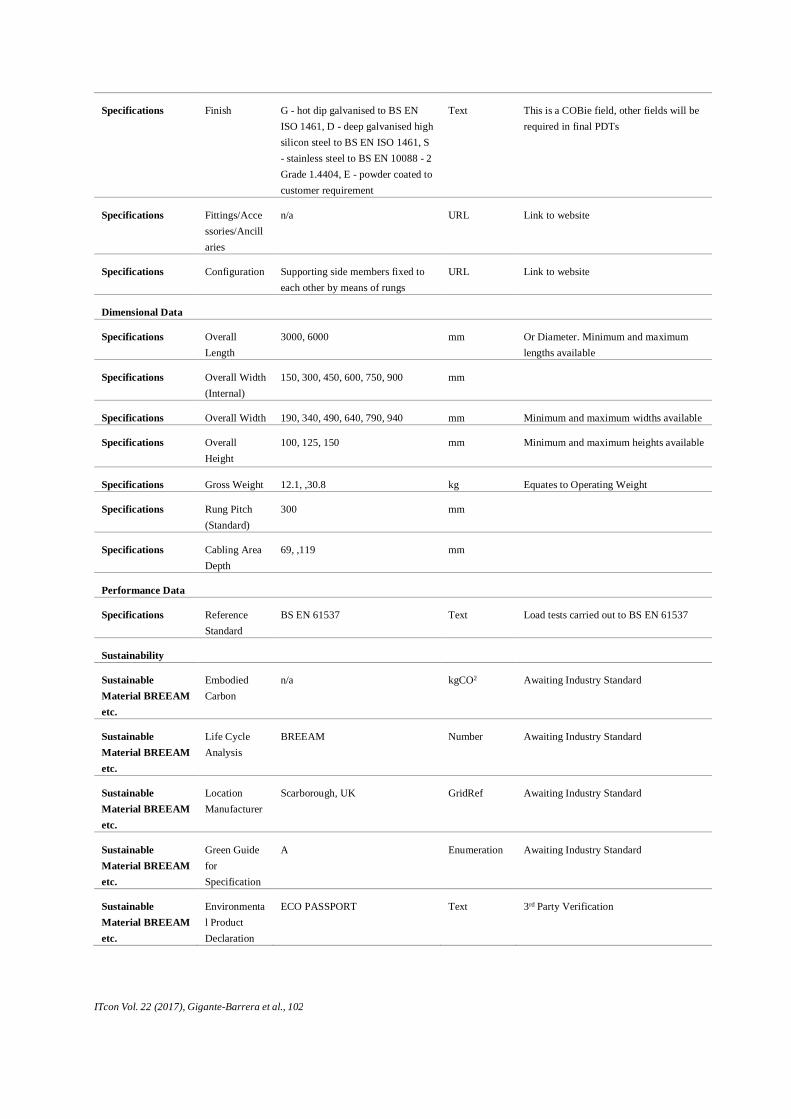
ITcon Vol. 22 (2017), Gigante-Barrera et al., 102
Specifications Finish G - hot dip galvanised to BS EN
ISO 1461, D - deep galvanised high
silicon steel to BS EN ISO 1461, S
- stainless steel to BS EN 10088 - 2
Grade 1.4404, E - powder coated to
customer requirement
Text This is a COBie field, other fields will be
required in final PDTs
Specifications Fittings/Acce
ssories/Ancill
aries
n/a URL Link to website
Specifications Configuration Supporting side members fixed to
each other by means of rungs
URL Link to website
Dimensional Data
Specifications Overall
Length
3000, 6000 mm Or Diameter. Minimum and maximum
lengths available
Specifications Overall Width
(Internal)
150, 300, 450, 600, 750, 900 mm
Specifications Overall Width 190, 340, 490, 640, 790, 940 mm Minimum and maximum widths available
Specifications Overall
Height
100, 125, 150 mm Minimum and maximum heights available
Specifications Gross Weight 12.1, ,30.8 kg Equates to Operating Weight
Specifications Rung Pitch
(Standard)
300 mm
Specifications Cabling Area
Depth
69, ,119 mm
Performance Data
Specifications Reference
Standard
BS EN 61537 Text Load tests carried out to BS EN 61537
Sustainability
Sustainable
Material BREEAM
etc.
Embodied
Carbon
n/a kgCO2 Awaiting Industry Standard
Sustainable
Material BREEAM
etc.
Life Cycle
Analysis
BREEAM Number Awaiting Industry Standard
Sustainable
Material BREEAM
etc.
Location
Manufacturer
Scarborough, UK GridRef Awaiting Industry Standard
Sustainable
Material BREEAM
etc.
Green Guide
for
Specification
A Enumeration Awaiting Industry Standard
Sustainable
Material BREEAM
etc.
Environmenta
l Product
Declaration
ECO PASSPORT Text 3rd Party Verification
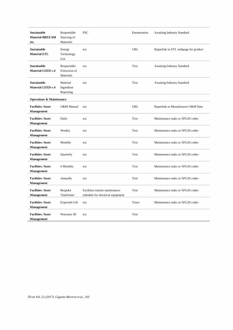
ITcon Vol. 22 (2017), Gigante-Barrera et al., 103
Sustainable
Material BREEAM
etc.
Responsible
Sourcing of
Materials
FSC Enumeration Awaiting Industry Standard
Sustainable
Material ETL
Energy
Technology
List
n/a URL Hyperlink to ETL webpage for product
Sustainable
Material LEED v.4
Responsible
Extraction of
Materials
n/a Text Awaiting Industry Standard
Sustainable
Material LEED v.4
Material
Ingredient
Reporting
n/a Text Awaiting Industry Standard
Operations & Maintenance
Facilities /Asset
Management
O&M Manual n/a URL Hyperlink to Manufacturer O&M Data
Facilities /Asset
Management
Daily n/a Text Maintenance tasks or SFG20 codes
Facilities /Asset
Management
Weekly n/a Text Maintenance tasks or SFG20 codes
Facilities /Asset
Management
Monthly n/a Text Maintenance tasks or SFG20 codes
Facilities /Asset
Management
Quarterly n/a Text Maintenance tasks or SFG20 codes
Facilities /Asset
Management
6 Monthly n/a Text Maintenance tasks or SFG20 codes
Facilities /Asset
Management
Annually n/a Text Maintenance tasks or SFG20 codes
Facilities /Asset
Management
Bespoke
Timeframe
Facilities routine maintenance
schedule for electrical equipment
Text Maintenance tasks or SFG20 codes
Facilities /Asset
Management
Expected Life n/a Years Maintenance tasks or SFG20 codes
Facilities /Asset
Management
Warranty ID n/a Text