lod offroad rear door linked install.pdf · 1 lod offroad jeep jk door linked rear bumper with tire...
TRANSCRIPT

1
LoD Offroad Jeep JK Door Linked Rear Bumper with Tire Carrier Installation Instructions Please read through the instructions before beginning any part of the installation process. Packaging List: 1-Rear Bumper 1-Tire Carrier Frame 1- 5 on 5” Mounting Plate 1-Adjustable Tire Mounting Bracket 2-Rubber Isolators 2-Factory Isolator Brackets 2-High-Lift Jack Mounts
2-Frame Backing Plates 1-CB Antenna Mount 1-Safety Chain Mount 1-Grease Zerk 1-Aluminum Cap w/ O-rings 1-Brass Wear Washer 1-Light Kit (Optional) 1-3rd Brake Light Mount (Optional)
Bolt List 7- 1/2”x4” Bolts 1- 1/2”x3-1/2” Bolt 2- 1/2”x4-1/2” Bolts 10- 1/2” Nuts 20- 1/2” Flat Washers 2- 7/16” x 1-1/2” Bolts 2- 7/16” Washers 7- 3/8” x 1” Bolts 7- 3/8” Nuts 12- 3/8” Flat Washers 1- 3/8”x1” Socket Allen Head Bolt

2

3

4
1. Begin with removing the spare tire as well as the tire mount located on the door. NOTE: You will need to re-use ALL of these bolts.
2. Remove the factory plastic bumper. There will be (6) six bolts securing the bumper to the frame and two additional bolts that mount two tabs between the bumper and frame. NOTE: You will need to re-use (4) four of these bolts.
5
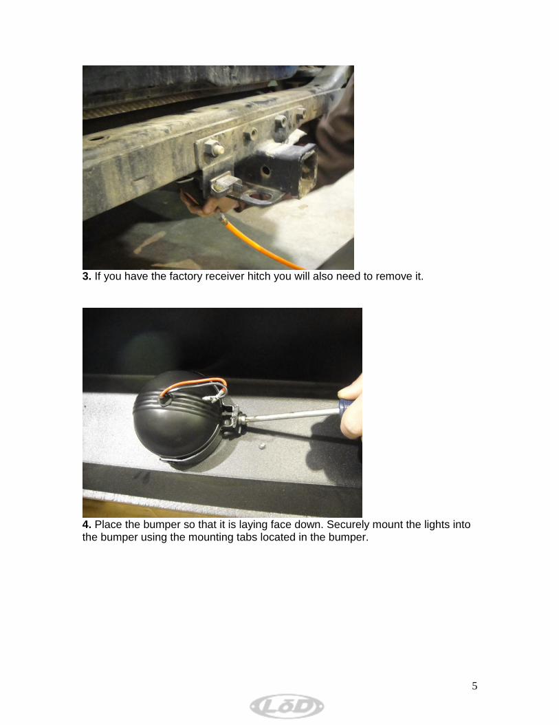
3. If you have the factory receiver hitch you will also need to remove it.
4. Place the bumper so that it is laying face down. Securely mount the lights into the bumper using the mounting tabs located in the bumper.

6
5. Included with the light kit is a wiring harness that will need to be plugged into each light.
6. Plug the wiring harness into each light. (The black to black and red to red wires) This harness is used to connect both lights to a common power source as well as ground.

7
7. Be sure that the wires are securely fastened. Tape excess wire together to keep it out of the way during the installation process. It is a good idea to add a waterproof shrink wrap or electrical tape to the connectors to keep any moisture out.
8. At this point you are now ready to begin the actual install of the bumper. Note: When sliding the bumper onto the jeep be sure to drape the excess wiring over the rear cross-member so that it doesn’t get pinched between the frame and bumper.

8
9. With some help slide the bumper onto the jeep. Note: Be sure to place wiring up on top the rear cross-member to prevent pinching the wires.
10. When mounting the bumper up for fitment it may help if you use a floor jack to hold up on the bumper.
9
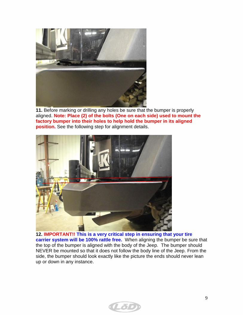
11. Before marking or drilling any holes be sure that the bumper is properly aligned. Note: Place (2) of the bolts (One on each side) used to mount the factory bumper into their holes to help hold the bumper in its aligned position. See the following step for alignment details.
12. IMPORTANT!! This is a very critical step in ensuring that your tire carrier system will be 100% rattle free. When aligning the bumper be sure that the top of the bumper is aligned with the body of the Jeep. The bumper should NEVER be mounted so that it does not follow the body line of the Jeep. From the side, the bumper should look exactly like the picture the ends should never lean up or down in any instance.

10
13. When aligning the bumper it is a good idea to slide the carrier onto the 1-1/2” hinge pin and swing it to the closed position. When in the closed position, from the side of the Jeep the carrier should look like the photo above. The carrier frame should lean slightly toward the front of the Jeep as the arrow shows. This will ensure that the hardware mounted later in the install will fit correctly and perform as it is intended to.
14. With the bumper aligned properly secure it into place and mark the (2) two holes. There will be (1) on each side of the frame that will need to be drilled. With the bumper still aligned lay under the Jeep toward the DRIVER side and mark the location of the slotted hole on the underneath side.

11
15. When marking any hole to drill be sure that your center punch and the punch mark is adequate enough to keep the drill bit from moving away from the desired hole location. Begin drilling the holes. Start with a small bit (3/16” works well) to pilot drill the holes. Drill these through both sides of the frame. Once the pilot holes are drilled the holes will need to be drilled again with a ½” drill bit. Note: The holes are being drill to accept a ½” bolt so if you think your holes are slightly off then it is a good idea to drill the hole a bit oversized so that the bolt will align properly.
12
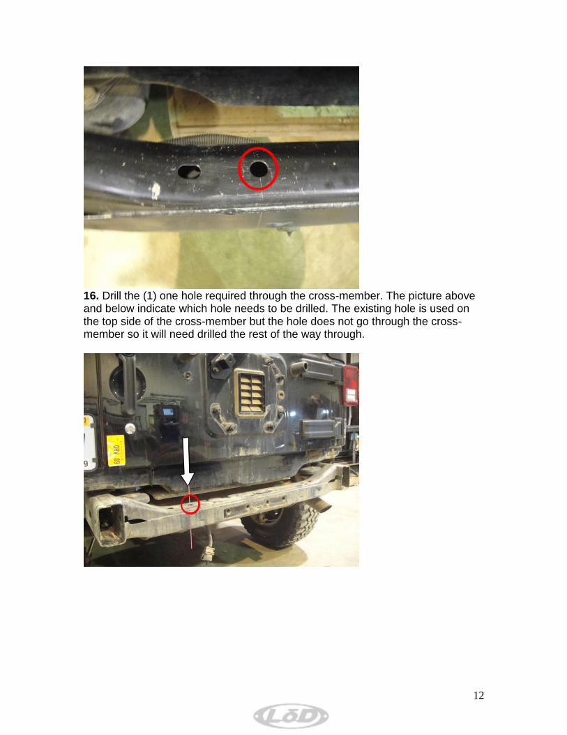
16. Drill the (1) one hole required through the cross-member. The picture above and below indicate which hole needs to be drilled. The existing hole is used on the top side of the cross-member but the hole does not go through the cross-member so it will need drilled the rest of the way through.

13
17. Once you have drilled the hole for each side and the one under the cross-member you can put the bumper back into place and begin bolting it up. First put the factory bolts into their existing holes on each side.
18. After the factory bolts are in place, put the ½” bolts supplied with the kit into their holes on each side. At this point leave all bolts loose enough to move the bumper around a bit.

14
19. Place the safety chain plate on the back side of the cross-member and put two of the ½” bolts through this bracket and the cross-member. You may need to wiggle the bumper to get these pushed through the holes.
Note: The cut-outs on the bottom side of the bumper are used to access the bolts that you just installed through the cross-member.

15
20. Now for the last two bolts to finish up installing the bumper itself. Two more ½” bolts are provided to go up through the cross-member. In total you should have place (8) eight ½” bolts into their location as well as (4) four of the factory bolts into their holes. A total of twelve bolts should be securing the bumper into place. Note: DO NOT FULLY TIGHTEN ANY THESE BOLTS until you be sure the bumper is properly aligned again. For proper alignment of all parts the bumper should look like the following picture.
(See step 13 for larger image) (See step 14 for larger image) 21. Once the bumpers alignment is correct you can fully tighten all the bolts to secure the bumper to the Jeep.
16
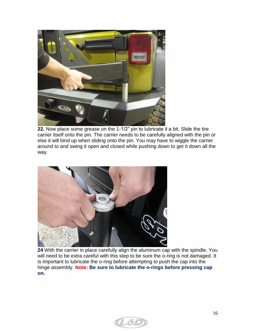
22. Now place some grease on the 1-1/2” pin to lubricate it a bit. Slide the tire carrier itself onto the pin. The carrier needs to be carefully aligned with the pin or else it will bind up when sliding onto the pin. You may have to wiggle the carrier around to and swing it open and closed while pushing down to get it down all the way.
24 With the carrier in place carefully align the aluminum cap with the spindle. You will need to be extra careful with this step to be sure the o-ring is not damaged. It is important to lubricate the o-ring before attempting to push the cap into the hinge assembly. Note: Be sure to lubricate the o-rings before pressing cap on.

17
25. Place the supplied grease zerk into the spindle on the carrier and pump plenty of grease into it. The grease will prevent the hinge from rusting.
26. Mount to Door Plate where the factory tire carrier was installed. Use the bolts from the factory mounts.
18
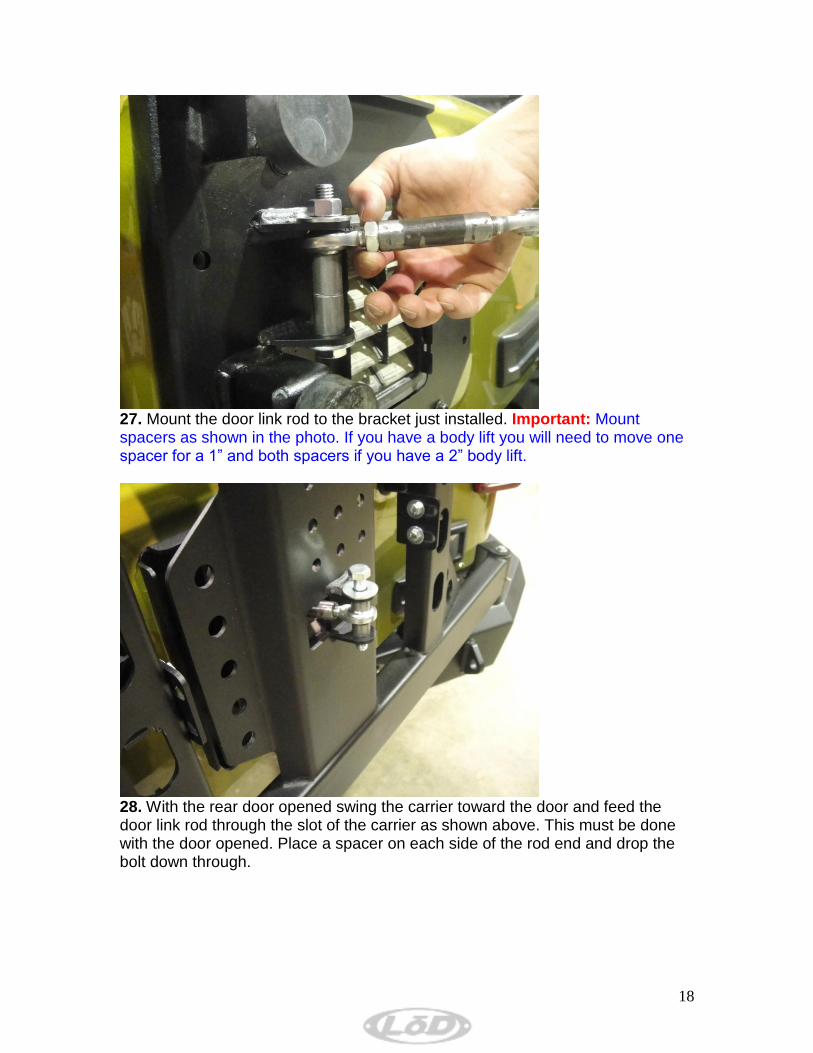
27. Mount the door link rod to the bracket just installed. Important: Mount spacers as shown in the photo. If you have a body lift you will need to move one spacer for a 1” and both spacers if you have a 2” body lift.
28. With the rear door opened swing the carrier toward the door and feed the door link rod through the slot of the carrier as shown above. This must be done with the door opened. Place a spacer on each side of the rod end and drop the bolt down through.

19
29. Thread the two rubber isolators into the plate mounted to the door. These will need to be adjusted in the following steps.
30. At this point you will need to carefully adjust the linkage rod to the proper length. To do this you will need to slowly close the rear door. As the door closes the carrier will continually get closer to the door. When the door shuts the carrier needs to be parallel with the rear of the jeep. Next you will need to adjust the rubber isolators installed in the previous step. They need to make firm contact with the carrier when the rear door is latched. If installed properly these will eliminate any rattle or movement of the tire carrier.

20
31. Now bolt the two L-shaped brackets on each side of the carrier using the (2) two 3/8” x 1” bolts provided with the kit. These brackets should mount to the inside of the carrier and wrap around the back toward the outside. Be sure to adjust these so that they make firm contact with the factory rubber isolators on the rear door.
IMPORTANT: The (4) four contact points across the rear door MUST be used to provide a rattle free system. The (2) two L-shaped brackets must make firm contact with the factory rubber isolators on the door. The isolators provided with

21
the kit must also be adjusted tight so that there is no movement between the rear door and carrier. Use the photo above for reference.
32. With the rear door opened mount the Tire Mounting bracket onto the carrier. Use the (3) three 7/16” x 1” bolts supplied with the kit. You will need to determine the height at which you want to carry your spare. Some prefer it mounted high for the trail while others mount it low for visibility on the road. The size of your spare will determine the lowest position in which you can run.
33. Slide the mount with the three studs sticking out on. The position of this mount is determined by the backspacing of your wheels. You will need to play around with this to get it in the proper position. When mounting the tire you want the wheel studs sticking out just enough to get the lug nuts started when the tire is all the way against the carrier frame.
22
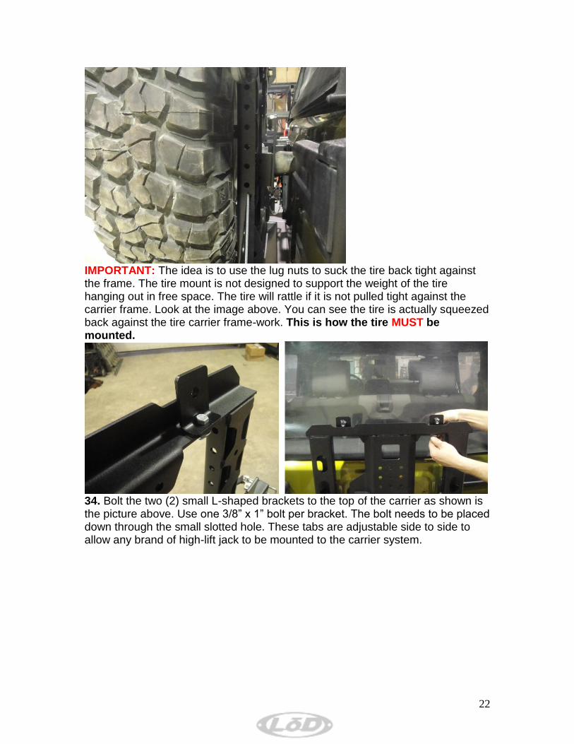
IMPORTANT: The idea is to use the lug nuts to suck the tire back tight against the frame. The tire mount is not designed to support the weight of the tire hanging out in free space. The tire will rattle if it is not pulled tight against the carrier frame. Look at the image above. You can see the tire is actually squeezed back against the tire carrier frame-work. This is how the tire MUST be mounted.
34. Bolt the two (2) small L-shaped brackets to the top of the carrier as shown is the picture above. Use one 3/8” x 1” bolt per bracket. The bolt needs to be placed down through the small slotted hole. These tabs are adjustable side to side to allow any brand of high-lift jack to be mounted to the carrier system.

23
35. Lay the high-lift jack across the top of the carrier frame and bolt it to the tabs you just placed on the top. Bolt the jack to the tabs using the two (2) 7/16” x 1-1/2” bolts.
36. That completes the install of the LoD Signature Series Tire Carrier. It is a good idea to go back and check all mounting hardware to be sure that all bolts are tight.

24
LoD Offroad Optional 3
rd Brake Light Mount
Installation Instructions
1. The door linked kit will look different but it’s the same idea. The two l-shaped brackets bolt to the top of the plate mounted to the door of the Jeep. The brackets will stick straight up. Mount them loosely until the next step.

25
2. Bolt the third brake light mount to the mounting tabs. Use the four (4) 5/16” x 1” bolts to achieve this. Tighten the bolts on the rear door first. Then adjust the mount so that it is straight up and down and tighten those bolts as well.
3. Plug the factory light back into the harness plug.

26
4. Screw the light into the mount. Use the screws provided with the bolt kit for the top two holes. Use the factory screws for the bottom two.